

Hobart 140GT17P, 140GT17K, 140GT17P5 Operation And Maintenance Manual With Illustrated Parts List
Page 1
OM-2029
010187
Revised 093089
Revised 031690
Revised 072790
Revised 040893
OPERATION AND MAINTENANCE MANUAL
with
ILLUSTRATED PARTS LIST
for
ENGINE-DRIVEN GENERATOR SETS
SERIES 6906
Models 140GT17P, 140GT17K, and 140GT17P5
140-KVA, 400-HZ, 115/200-V AC, 3-PHASE
SPEC. No. DESCRIPTION
6906-1 Basic Series 6906 generator set, trailer-mounted
6906-2 Basic Series 6906 generator set, truck-mounted
6906-3 Basic Series 6906 generator set, mounted on
5th-wheel trailer, with T-R provisions, fuel tank,
battery, and trays for battery and cables.
6906-4 Basic Series 6906 generator set, truck-mounted,
and equipped with magnetic amplifier type voltage
regulator, Part No. 281407
6906-5 Basic Series 6906 generator set, mounted on 5th-wheel
trailer
6906-6 Basic Series 6906 generator set, mounted on 5th-wheel
trailer, with fuel tank, cable tray, battery/cable tray,
rear fenders, and rear bumper
Hobart Brothers Company
Airport Systems Group
Ground Power Equipment
Troy, Ohio 45373
U.S.A.
Page 2

This page intentionally left blank
Page 3

SAFETY INSTRUCTIONS AND WARNINGS FOR ELECTRICAL POWER EQUIPMENT
WARNING
ELECTRIC SHOCK can KILL. Do not touch live electrical parts.
ELECTRIC ARC FLASH can injure eyes, burn skin, cause equipment damage, and ignite combustible
material. DO NOT use power cables to break load and prevent tools from causing short circuits.
IMPROPER PHASE CONNECTION, PARALLELING, OR USE can damage this and attached
equipment.
Important:- Protect all operating personnel. Read, understand, and follow all instructions in
the Operating/Instruction Manual before installing, operating, or servicing the equipment. Keep
the manual available for future use by all operators.
A. GENERAL
Equipment that supplies electrical power can cause serious injury or death, or damage to other equipment
or property. The operator must strictly observe all safety rules and take precautionary actions. Safe practices
have been developed from past experience in the use of power source equipment. While certain practices below apply only to electrically-powered equipment, other practices apply to engine-driven equipment, and some
practices to both.
B. SHOCK PREVENTION
Bare conductors, or terminals in the output circuit, or ungrounded, electrically-live equipment can fatally
shock a person. Have a certified electrician verify that the equipment is adequately grounded and learn what
terminals and parts are electrically HOT. Avoid hot spots on machine. Use proper safety clothing, procedures,
and test equipment.
The electrical resistance of the body is decreased when wet, permitting dangerous currents to flow
through it. When inspecting or servicing equipment, do not work in damp areas. Stand on a dry rubber mat
or dry wood, use insulating gloves when dampness or sweat cannot be avoided. Keep clothing dry, and
never work alone
1. Installation and Grounding of Electrically Powered Equipment
Equipment driven by electric motors (rather than by diesel or gasoline engines) must be installed and
maintained in accordance with the National Electrical Code, ANSI/NFPA 70, or other applicable codes. A
power disconnect switch or circuit breaker must be located at the equipment. Check the nameplate for voltage, frequency, and phase requirements. If only 3-phase power is available, connect any single-phase rated
equipment to only two wires of the 3-phase line. DO NOT CONNECT the equipment grounding conductor
(lead) to the third live wire of the 3-phase line, as this makes the equipment frame electrically HOT, which can
cause a fatal shock.
Always connect the grounding lead, if supplied in a power line cable, to the grounded switch box or building ground. If not provided, use a separate grounding lead. Ensure that the current (amperage) capacity of
the grounding lead will be adequate for the worst fault current situation. Refer to the National ElectricalCode
ANSI/NFPA 70 for details. Do not remove plug ground prongs. Use correctly mating receptacles.
2. Output Cables and Terminals
Inspect cables frequently for damage to the insulation and the connectors. Replace or repair cracked or
worn cables immediately. Do not overload cables. Do not touch output terminal while equipment is energized.
3. Service and Maintenance
This equipment must be maintained in good electrical and mechanical condition to avoid hazards stemming from disrepair. Report any equipment defect or safety hazard to the supervisor and discontinue use of
the equipment until its safety has been assured. Repairs should be made by qualified personnel only.
Before inspecting or servicing electrically-powered equipment, take the following precautions:
Page 4

a. Shut OFF all power at the disconnecting switch or line breaker before inspecting or servicing the
equipment.
b. Lock switch OPEN (or remove line fuses) so that power cannot be turned on accidentally.
c. Disconnect power to equipment if it is out of service.
d. If troubleshooting must be done with the unit energized, have another person present who is trained in
turning off the equipment and providing or calling for first aid.
C . FIRE AND EXPLOSION PREVENTION
Fire and explosion are caused by electrical short circuits, combustible material near engine exhaust piping, misuse of batteries and fuel, or unsafe operating or fueling conditions.
1. Electrical Short Circuits and Overloads
Overloaded or shorted equipment can become hot enough to cause fires by self destruction or by causing
nearby combustibles to ignite. For electrically-powered equipment, provide primary input protection to remove
short circuited or heavily overloaded equipment from the line.
2. Batteries
Batteries may explode and/or give off flammable hydrogen gas. Acid and arcing from a ruptured battery
can cause fires and additional failures. When servicing,do not smoke, cause sparking, or use open flame
near the battery.
3. Engine Fuel
Use only approved fuel container or fueling system. Fires and explosions can occur if the fuel tank is not
grounded prior to or during fuel transfer. Shut unit DOWN before removingfueltank cap. DO NOT completely fill tank, because heat from the equipment may cause fuel expansion overflow. Remove all spilled fuel
IMMEDIATELY, including any that penetrates the unit. After clean-up, open equipment doors and blowfumes
away with compressed air.
D. TOXIC FUME PREVENTION
Carbon monoxide - Engine exhaust fumes can kill and cause health problems. Pipe or vent the exhaust
fumes to a suitable exhaust duct or outdoors. Never locate engine exhausts near intake ducts of air conditioners.
E. BODILY INJURY PREVENTION
Serious injury can result from contact with fans inside some equipment. Shut DOWN such equipment for
inspection and routine maintenance. When equipment is in operation, use extreme care in doing necessary
trouble-shooting and adjustment. Do not remove guards while equipment is operating.
F. MEDICAL AND FIRST AID TREATMENT
First aid facilities and a qualified first aid person should be available for each shift for immediate treatment of all injury victims. Electric shock victims should be checked by a physician and taken to a hospital immediately if any abnormal signs are observed.
EMERGENCY FIRST AID
Call physician immediately. Seek additional assistance. Use First Aid techniques recommended
by American Red Cross until medical help arrives.
IF BREATHING IS DIFFICULT, give oxygen, if available, and have victim lie down. FOR ELECTRICAL SHOCK, turn off power. Remove victim; if not breathing, begin artificial respiration, preferably
mouth-to-mouth. If no detectable pulse, begin external heart massage. CALL EMERGENCY RESCUE
SQUAD IMMEDIATELY.
G. EQUIPMENT PRECAUTIONARY LABELS
Inspect all precautionary labels on the equipment monthly. Order and inspect all labels that cannot be
easily read.
Page 5

OM-2029
LIST OF EFFECTIVE PAGES
CHAPTER/ CHAPTER/
SECTION PAGE DATE SECTION PAGE DATE
List of 1 Mar 16/90 1-3 1 Sept 30/89
Effective 2 Mar 16/90 1-3 2 Sept 30/89
Pages 1-3 3 July 27/90
1-3 4 July 27/90
Introduction 1/2 Sept 30/89 1-3 5 Sept 30/89
1-3 6 July 27/90
Contents 1 Sept 30/89 1-3 7 July 27/90
Contents 2 Sept 30/89 1-3 8 Sept 30/89
Contents 3 Sept 30/89
Contents 4 Sept 30/89 2-1 1 Sept 30/89
Contents 5 Sept 30/89 2-1 2 Sept 30/89
Contents 6 Sept 30/89 2-1 3 Sept 30/89
Contents 7 Sept 30/89 2-1 4 Sept 30/89
Contents 8 Sept 30/89 2-1 5 Sept 30/89
Contents 9 Sept 30/89 2-1 6 Sept 30/89
Contents 10 Sept 30/89 2-1 7 Sept 30/89
Contents 11 Sept 30/89 2-1 8 Sept 30/89
Contents 12 Sept 30/89 2-1 9 Sept 30/89
2-1 10 Sept 30/89
1-1 1 July 27/90 2-1 11 Sept 30/89
1-1 2 Sept 30/89 2-1 12 Sept 30/89
1-1 3 Mar 16/90 2-1 13 Sept 30/89
1-1 4 Mar 16/90 2-1 14 Sept 30/89
1-1 5 July 27/90
1-1 6 July 27/90 2-2 1 Sept 30/89
1-1 7 Sept 30/89 2-2 2 Sept 30/89
1-1 8 Sept 30/89 2-2 3 Sept 30/89
1-1 9 Sept 30/89 2-2 4 Sept 30/89
1-1 10 Sept 30/89 2-2 5 Sept 30/89
1-1 11 Sept 30/89 2-2 6 Sept 30/89
1-1 12 Sept 30/89
1-1 13 Sept 30/89 2-3 1 July 27/90
1-1 14 July 27/90 2-3 2 Sept 30/89
1-1 15 July 27/90 2-3 3 July 27/90
1-1 16 July 27/90 2-3 4 July 27/90
1-1 17 July 27/90 2-3 5 Sept 30/89
1-1 18 Sept 30/89 2-3 6 Sept 30/89
1-1 19 Sept 30/89 2-3 7 Sept 30/89
1-1 20 Sept 30/89 2-3 8 Sept 30/89
1-1 21 Sept 30/89 2-3 9 Mar 16/90
1-1 22 Sept 30/89 2-3 10 Mar 16/90
1-1 23 Sept 30/89 2-3 11 Mar 16/90
1-1 24 Sept 30/89 2-3 12 Mar 16/90
2-3 13 Mar 16/90
1-2 1 Sept 30/89 2-3 14 Mar 16/90
1-2 2 Sept 30/89
1-2 3 Sept 30/89
1-2 4 Sept 30/89
July 27/90 Revised List of Effective Pages
Page1
Page 6

OM-2029
LIST OF EFFECTIVE PAGES (CONTINUED)
CHAPTER/ CHAPTER/
SECTION PAGE DATE SECTION PAGE DATE
3-1 1 Sept 30/89 4-3 8 Sept 30/89
3-1 2 Sept 30/89 4-3 9 July 27/90
3-1 3 Sept 30/89 4-3 10 Sept 30/89
3-1 4 Sept 30/89 4-3 11 Sept 30/89
3-1 5 July 27/90 4-3 12 Sept 30/89
3-1 6 Sept 30/89 4-3 13 Sept 30/89
3-1 7 Sept 30/89 4-3 14 Sept 30/89
3-1 8 Sept 30/89 4-3 15 Sept 30/89
3-1 9 Sept 30/89 4-3 16 Sept 30/89
3-1 10 Sept 30/89 4-3 17 July 27/90
3-1 11 Sept 30/89 4-3 18 July 27/90
3-1 12 Sept 30/89 4-3 19 July 27/90
3-1 13 Sept 30/89 4-3 20 Sept 20/89
3-1 14 Sept 30/89 4-3 21 July 27/90
3-1 15 July 27/90 4-3 22 Sept 30/89
3-1 16 July 27/90 4-3 23 Sept 30/89
3-1 17 July 27/90 4-3 24 Sept 30/89
3-1 18 July 27/90 4-3 25 July 27/90
3-1 19 Sept 30/89 4-3 26 Sept 30/89
3-1 20 July 27/90 4-3 27 Sept 30/89
3-1 21 Sept 30/89 4-3 28 Sept 30/89
3-1 22 Sept 30/89 4-3 29 July 27/90
3-1 23 Sept 30/89 4-3 30 July 27/90
3-1 24 Sept 30/89 4-3 31 July 27/90
3-1 25 Sept 30/89 4-3 32 Sept 30/89
3-1 26 Sept 30/89 4-3 33 July 27/90
3-1 27 Sept 30/89 4-3 34 Sept 30/89
3-1 28 Sept 30/89 4-3 35 July 27/90
4-3 36 Mar 16/90
4-1 1 July 27/90 4-3 37 July 27/90
4-1 2 Mar 16/90 4-3 38 Mar 16/90
4-3 39 July 27/90
4-2 1 Sept 30/89 4-3 40 July 27/90
4-2 2 Mar 16/90 4-3 41 July 27/90
4-2 3 Mar 16/90 4-3 42 July 27/90
4-2 4 Mar 16/90 4-3 43 July 27/90
4-3 44 July 27/90
4-3 1 Sept 30/89
4-3 2 Sept 30/89 5-0 1 July 27/90
4-3 3 Sept 30/89 5-0 2 Sept 30/89
4-3 3A July 27/90
4-3 3B July 27/90 6-0 1 July 27/90
4-3 3C July 27/90 6-0 2 Sept 30/89
4-3 3D July 27/90
4-3 4 Sept 30/89
4-3 5 Mar 16/90
4-3 6 Mar 16/90
4-3 7 July 27/90
List of Effective Pages July 27/90 Revised
Page 2
Page 7

OM-2029
Table of Contents
WARNING
LIST OF EFFECTIVE PAGES
INTRODUCTION
SUBJECT CHAPTER/SECTION PAGE
CHAPTER 1. DESCRIPTION/OPERATION
SECTION 1. DESCRIPTION 1-1 1
1. General 1-1 1
2. Orientation 1-1 1
3. Special Features 1-1 1
A.Protective Monitor 1-1 1
B.Voltage Regulator 1-1 1
C. Dual Outputs 1-1 3
D. Electric Governor 1-1 3
E. Hinged Front Panel on Generator
Control Box 1-1 3
4. Identification 1-1 5
5. Optional Equipment 1-1 6
A. Trailer 1-1 6
B. Transformer-Rectifier (6906-3 and
6906-4 ONLY) 1-1 6
C. Truck 1-1 6
D. Quick Start Kit 1-1 6
6. Canopy 1-1 6
7. Engine, Generator, and Controls
Assembly 1-1 6
A. Basic Engine 1-1 6
B. Engine Manufacturer’s Equipment 1-1 7
C. Hobart Engine Equipment 1-1 7
(1) Electric governor system 1-1 7
(a) Magnetic pickup 1-1 7
(b) Control unit 1-1 7
(c) Actuator 1-1 7
(2) Engine electrical system 1-1 7
(3) Engine protective devices 1-1 9
(4) Air cleaner 1-1 9
(5) Water Temperature Sender 1-1 10
(6) Oil Pressure Sender 1-1 10
(7) Exhaust system 1-1 10
(8) Radiator 1-1 10
D. Generator 1-1 11
September 30/89 Revised Table of Contents
Page 1
Page 8

OM-2029
SUBJECT CHAPTER/SECTION PAGE
E. Control Box Assembly 1-1 11
(1) Generator Control Box Front Panel
Components 1-1 12
(a) Generator output monitors (meters) 1-1 12
(b) Meter and line switches 1-1 12
(c) Indicating lights 1-1 12
(d) Load contactor circuit breaker 1-1 12
(e) Protective system circuit breaker 1-1 12
(2) Generator Control Box Interior Components
(Figure 7) 1-1 14
(a) Sensing modules 1-1 14
(b) Memory and time delay module 1-1 14
(c) Plug-interlock relays 1-1 15
(d) Test-bank switches 1-1 15
(e) Resistor 1-1 15
(f) Fuse-interlock relay 1-1 15
(g) Auxiliary underfrequency relay 1-1 15
(h) Regulated-diagnostic switch 1-1 15
(j) Excitation-deenergization relay 1-1 15
(k) Voltage Regulator 1-1 17
F. Engine Control Panel (See Fig. 9) 1-1 18
(1) Engine instruments 1-1 18
(2) Engine and generator controls 1-1 18
H. Power Module Panel Assembly 1-1 20
(1) Load contactor 1-1 21
(2) Current transformers 1-1 21
(3) Rectifiers 1-1 21
(4) Overload module 1-1 22
(5) Terminal boards 1-1 22
SECTION 2. PREPARATION FOR
USE, STORAGE, OR SHIPPING 1-2 1
1. Preparation for Use 1-2 1
A. General 1-2 1
B. Inspection/Check 1-2 1
(a) Fuel 1-2 1
(b) Engine coolant 1-2 1
(c) Engine lubricating oil 1-2 1
C. Installing Output Cables 1-2 2
2. Preparation for Storage 1-2 3
A. General 1-2 3
B. Temporary Storage 1-2 3
C. Long Time Storage (Over 30 Days) 1-2 3
Table of Contents September 30/89 Revised
Page 2
Page 9

OM-2029
SUBJECT CHAPTER/SECTION PAGE
SECTION 3. OPERATION 1-3 1
1.General 1-3 1
2. Operating the Generator Set 1-3 1
A. Pre-start Inspection 1-3 1
B. Normal Engine Starting Procedures 1-3 1
C. Cold Weather Engine Starting Procedures 1-3 4
D. Preparation for Power Delivery
(Normal Automatic Voltage Control) 1-3 5
E. Power Delivery 1-3 5
No. 1 Output Circuit 1-3 5
No. 2 Output Circuit 1-3 6
F. Discontinue Power Delivery 1-3 6
K. Stopping the Engine 1-3 6
3. Transformer-Rectifier Operation 1-3 6
A. Direct Current Power Delivery 1-3 6
B. Simultaneous 28.5-V DC and
115-V AC Power Delivery 1-3 7
4. Trailer Operation (Optional) 1-3 8
A. Towing 1-3 8
B. Parking 1-3 8
CHAPTER 2. SERVICE
SECTION 1. MAINTENANCE 2-1 1
1. General 2-1 1
2. Inspection 2-1 1
3. Lubrication 2-1 1
A. General 2-1 1
B. Generator 2-1 1
C. Generator Controls 2-1 1
D. Engine 2-1 1
(1) Lubrication schedule 2-1 2
(2) Oil specification 2-1 2
(3) Oil viscosity 2-1 2
(4) Changing engine oil 2-1 2
(5) Changing engine oil filter 2-1 2
E. Starter 2-1 2
4. Air Cleaner Service 2-1 3
A. Cartridge Removal (See Fig. 2) 2-1 3
B. Cartridge Installation (See Fig. 2) 2-1 4
5. Engine Fuel 2-1 4
A. Quality 2-1 4
B. Fuel Filter 2-1 4
September 30/89 Revised Table of Contents
Page 3
Page 10

OM-2029
SUBJECT CHAPTER/SECTION PAGE
6. Engine Cooling System 2-1 5
A. General 2-1 5
B. Radiator Cap 2-1 5
(1) General 2-1 5
(2) Removal 2-1 5
(3) Installation 2-1 5
C. Warm Weather Operation 2-1 5
D. Cold Weather Operation 2-1 5
(1) General 2-1 5
(2) Checking coolant solution 2-1 6
(3) Preparing the coolant solution 2-1 6
(4) Installing the antifreeze solution 2-1 6
E. Draining the Cooling System 2-1 6
F. Cleaning the Cooling System 2-1 7
G. Cleaning the Radiator Core 2-1 7
H. Filling the Cooling System 2-1 7
7. Generator Maintenance 2-1 8
A. Cleaning 2-1 8
B. Adjustment 2-1 8
8. Drive Belts 2-1 8
A. Checking Belt Tension 2-1 8
B. Belt Adjustment 2-1 8
9. Trailer and Truck Maintenance 2-1 9
A. General 2-1 9
B. Cleaniness 2-1 9
C. Grease application 2-1 9
D. Lubrication chart 2-1 9
2-1 10
E. Checking Wheel Bearings 2-1 12
F. Adjusting Wheel Bearings 2-1 12
10. Battery Service 2-1 12
A. General 2-1 12
B. Battery Location and Accessibility 2-1 12
C. Battery Care 2-1 12
D. Liquid Level 2-1 12
E. Cleaning the Battery 2-1 13
F. Testing the Battery 2-1 13
11. Service Helps 2-1 13
A. Wiring 2-1 13
B. Generator Exciter 2-1 13
SECTION 2. INSPECTION/CHECK 2-2 1
1. General 2-2 1
2. Engine 2-2 1
A. Fuel (See Fig. 1 for time schedules) 2-2 1
B. Lubrication 2-2 1
C. Coolant 2-2 1
D. V-Belts 2-2 1
E. Exhaust System 2-2 1
Table of Contents September 30/89 Revised
Page 4
Page 11

OM-2029
SUBJECT CHAPTER/SECTION PAGE
3.Electrical System (12-V DC) 2-2 3
A. Lights 2-2 3
B. Circuit Breakers 2-2 3
C. Wiring and Connections 2-2 3
4. Electrical System (115-V AC) 2-2 4
A. Monitoring Instruments 2-2 4
B. Indicating Lights 2-2 4
C. Protective Modules 2-2 4
D. Wiring and Connections 2-2 4
5. Trailer and Truck 2-2 5
SECTION 3. ADJUSTMENT/TEST 2-3 1
1. General 2-3 1
2. Generator Set Test 2-3 1
A. Pre-operational Test Procedures 2-3 1
B. Operational Test Procedures 2-3 1
3. Generator Set Adjustment 2-3 8
A. Generator Adjustment 2-3 8
B. Generator Control Adjustments 2-3 8
C. Basic Engine Adjustments 2-3 9
D. Engine Accessories Adjustment 2-3 9
E. Electric Governor System Adjustment 2-3 9
(1) Actuator linkage adjustment 2-3 9
(2) Magnetic pickup adjustment 2-3 11
(3) Governor Control Unit Adjustment 2-3 12
5. Generator and Exciter Test 2-3 14
6. Diode Test 2-3 14
CHAPTER 3. TROUBLESHOOTING
SECTION 1. TROUBLESHOOTING
PROCEDURES 3-1 1
1. General 3-1 1
2. Troubleshooting Chart 3-1 1
3. Equipment for Troubleshooting 3-1 2
4. Safety 3-1 2
5. Parts Replacement 3-1 2
6. Test Values 3-1 2
7. Checking Connections and Leads 3-1 3
8. Electric Governor Troubleshooting 3-1 3
9. Engine Troubleshooting Procedures 3-1 3
A. General 3-1 3
September 30/89 Revised Table of Contents
Page 5
Page 12

OM-2029
SUBJECT CHAPTER/SECTION PAGE
CHAPTER 4. ILLUSTRATED PARTS LIST
SECTION 1. INTRODUCTION 4-1 1
1. General 4-1 1
2. Purpose 4-1 1
3. Arrangement 4-1 1
4. Explanation of Parts List 4-1 1
A. Contents 4-1 1
B. Parts List Form 4-1 2
(1) FIGURE-ITEM NO. Column 4-1 2
(2) HOBART PART NUMBER Column 4-1 2
(3) NOMENCLATURE Column 4-1 2
(4) REC. SPARES Column 4-1 2
(5) “EFF” (Effectivity) Column 4-1 2
(6) UNITS PER ASSEMBLY Column 4-1 2
SECTION 2. MANUFACTURERS’
CODES 4-2 1
1. Explanation of Manufacturers’
(Vendors’) Code List 4-2 1
SECTION 3. PARTS LIST 4-3 1
1. Explanation of Parts List Arrangement 4-3 1
2. Symbols and Abbreviations 4-3 1
SECTION 4. NUMERICAL INDEX
1. Explanation of Numerical Index 4-3 1
CHAPTER 5. OPTIONAL EQUIPMENT
CHAPTER 6. MANUFACTURERS’ LITERATURE
UNUSUAL SERVICE CONDITIONS
Table of Contents September 30/89 Revised
Page 6
Page 13
Addendum to
Operation and Maintenance Manual OM-2029
covering a Modification to
Generator Set Specifications 6906-2 and 6906-4
1. Scope
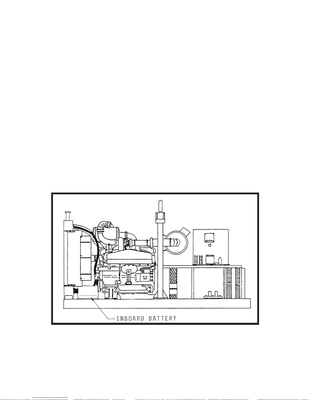
This addendum increases the coverage of Hobart Manual OM-2029 to include a modification to Gene- rator Set Specification Numbers 6906-2 and 6906-4
erator set is equipped with a battery that is installed in the engine compartment of the generator set,
rather than in a compartment on the truck.
(truck-mounted units).
(See Figure 1).
As per this modification, the gen-
2. Description
In regard to physical appearance, electrical output ratings, and operation, the Specification 6906-2 or
6906-4 generator set with the aforementioned modification, as covered by this addendum, is identical to
all other Specification 6906-2 or 6906-4 generator sets.
OM-2029
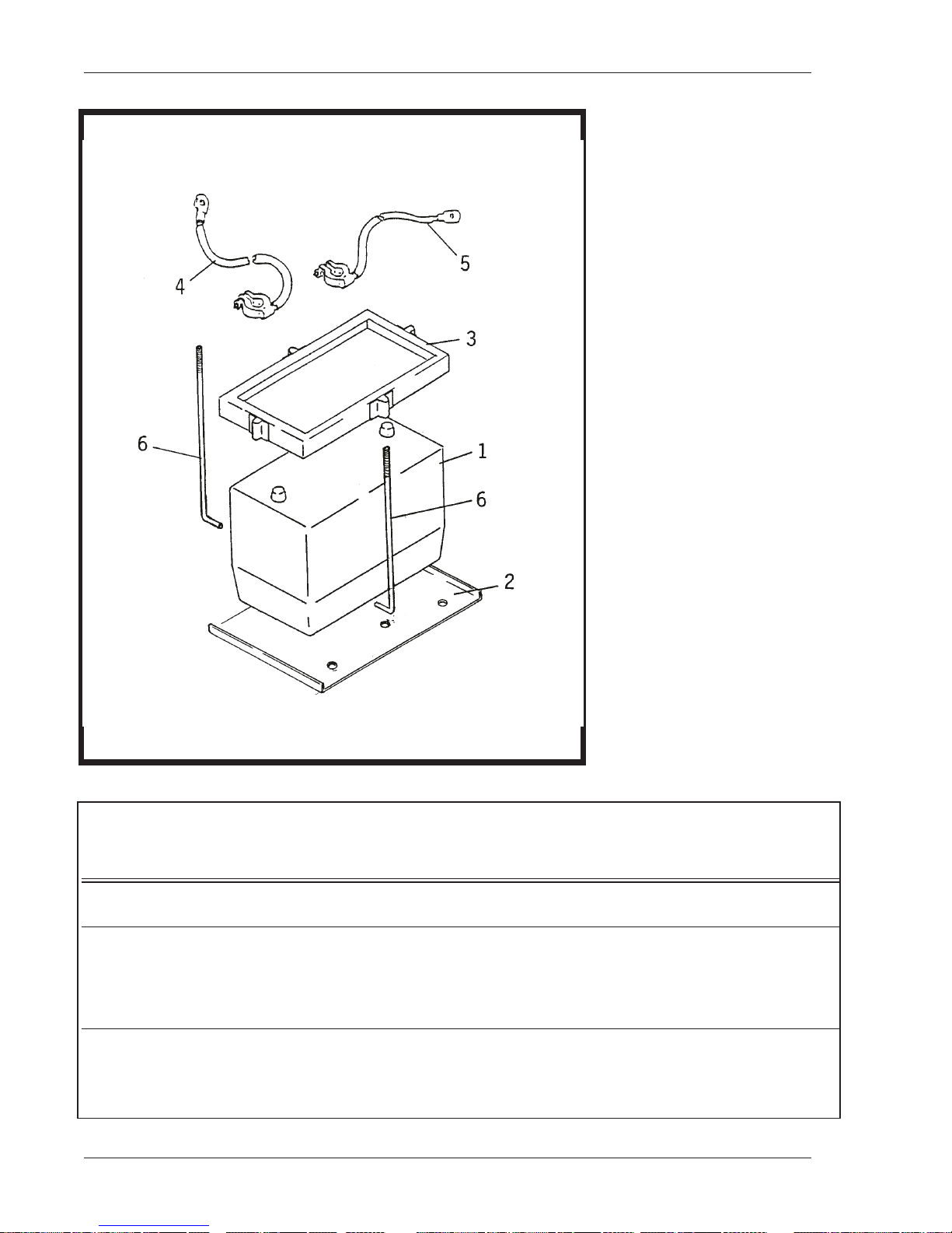
Figure 2 is an illustration that shows the various components of the inboard battery kit, which is identified
as Hobart Part No. 281926. This illustration is accompanied by a parts list whose item numbers correspond with the call-out numbers on the illustration.
June 6/90 Addendum
Location of Inboard Battery
Figure 1
Page 1
Page 14
OM-2029
Inboard Battery Kit
Part No. 281926
Figure 2
FIGURE HOBART PER
ITEM NO. PART NO. 1234567 EFF ASSY
2- 281926 BATTERY INSTALLATION
1 281871-1 . BATTERY, 12 VOLTS 1
2 281927 . SUPPORT, BATTERY 1
3 181831 . FRAME, HOLD-DOWN, BATTERY 1
4 481209-4 . CABLE, POSITIVE 1
5 383067-5 . CABLE, NEGATIVE 1
6 5CW-2048 . ROD, BATTERY, SUPPORT, ASSY 2
Addendum June 6/90
Page 2
NOMENCLATURE UNITS
(For units having ONE battery) REF
Page 15

3. Customer Service
If you have any questions concerning your Hobart Ground Airport Systems Group equipment, you are invited to contact our service department by mail, telephone, or FAX.
Write: Hobart Brothers Company
Airport Systems Group
1177 Trade Road East
Troy, Ohio 45373, U.S.A.
Telephone: (513) 332-5060 (Service Assistance)
(513) 332-5050 (Parts Replacement)
FAX: (513) 332-5121
OM-2029
June 6/90 Addendum
Page 3
Page 16

OM-2029
This page intentionally left blank.
Addendum June 6/90
Page 4
Page 17
Page 18

Page 19

OM-2029
CHAPTER 1. DESCRIPTION/OPERATION
SECTION 1. DESCRIPTION
1. General
Generator sets
rations of the set are identified by adding a dash number
6906 generator sets feature armatures with Hoover Bearings, Browning Coupler, and different magnetic
pole construction for the generator revolving field.
The basic generator set which includes the engine, generator and all controls is identical for all models.
Differences between models are those required by their respective mountings, such as trailer mounting,
truck mounting, etc., or by other special features. Identificationof different models within the Series will be
explained later in the Description. Information and instructions throughout the manual apply to all models.
Information which applies only to a certain model will be qualified and identified as such.
The purpose of the generator set is to generate and deliver regulated, 400-Hz electrical power to a parked
(or towed)
running. The engine, generator, and controls are designed into a compact unit which is easily removable
from a tow tractor. See Figure 2 for specifications and capabilities.
(see Fig. 1)
aircraft for operation of the aircraft’s electrical equipment when the on-board generators are not
covered by the manual are identified by Series No. 6906. The various configu-
(-1, -2, etc.)
suffix to the Series number. Series
2. Orientation
For purpose of orientation and to familiarize operators and maintenance personnel with the location of
components, the radiator is considered to be at the FRONT of the unit. The generator and controls are at
the REAR. RIGHT and LEFT are determined by standing at the rear end facing the machine. Thus, the
generator controls are mounted on the REAR of the unit.
3. Special Features
The generator set has many special features which are later described more fully under the assemblies in
which they appear. Some of the main features are mentioned here and described briefly.
A. Protective Monitor
A single, solid-state device
ator output circuit and functions to cause the load to be disconnected from the generator if an abnormal condition of voltage, frequency, or load develops.
B. Voltage Regulator
A solid-state, adjustable voltage regulator
6906-1 and 6906-2 generator sets. This voltage regulator provides automatic voltage regulation at
the aircraft
cable sizes and lengths. A magnetic amplifier type voltage regulator
used on Specification 6906-3, Specification 6906-4, Specification 6906-5 and Specification 6906-6
generator sets. This regulator is also adjustable for a variety of output cable sizes and lengths.
July 27/90 Revised 1-1
(or distribution panel when applicable)
(4, Fig. 8)
receives signals from all of the fault sensing units in the gener-
(Hobart part number 489812A)
. This regulator is adjustable for a variety of output
is used on Specification
(Hobart part no. 281407)
is
Page 1
Page 20
OM-2029
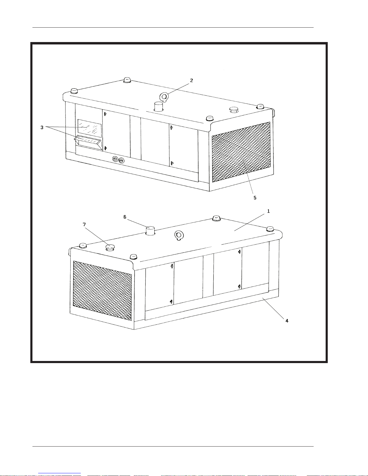
1. Canopy 5. Engine fan exhaust vent
2. Lifting eye 6. Engine exhaust pipe
3. Windows 7. Radiatorcap
4. Mounting frame
1-1 September 30/89 Revised
Page 2
Generator Set
(without trailer)
Figure 1
Page 21
OM-2029
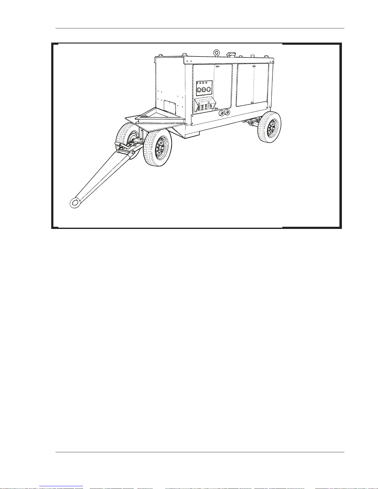
Generator Set Mounted on Fifth-Wheel Trailer
Figure 1A
C. Dual Outputs
Each generator set is equipped with two output circuits and dual controls so that power may be delivered to an aircraft requiring two inputs, or to one or two aircraft with single input requirements.
D. Electric Governor
The engine is equipped with an all electric type governor kit
ment more fully described under the engine description.
E. Hinged Front Panel on Generator Control Box
The control box is equipped with a hinged front panel. Located conveniently on this panel are
switches, meters, indicator lights, and circuit breakers for controlling and monitoring the generator.
This panel swings out to provide easy access to the voltage regulator, PC boards, and relays which
are used to control and monitor the generator.
(9and 15, Fig. 3)
and other special equip-
March 16/90 Revised 1-1
Page 3
Page 22

OM-2029
PHYSICAL
BASIC UNIT
Length overall 109.6 inches
Width 45.5 inches
Height overall 62.0 inches
Weight 3500 pounds
FOUR-WHEEL TRAILER-MOUNTED UNIT
Length overall 119.0 inches
Width 80.0 inches
Height 79.0 inches
Weight 5400 pounds
FIFTH-WHEEL TRAILER MOUNTED UNIT
Length overall, with tongue up 160 inches
Length overall, with tongue down 228 inches
Width 84 inches
Height 84 inches
Weight
(with 1/4 tank of fuel
and no cables)
7160 pounds
GENERATOR
Output power rating 140 KVA
Output voltage 115/200 V
Rated load capacity 404 Amp
Frequency
Output kilowatts 112 KW
Power factor 0.8 PF
Duty cycle 100%
Operating speed at 400 Hz 1714 RPM
Overload capacity 505 Amp
(125% of rated load capacity)
(cycles-per-second)
400 Hz
(2784 mm)
(1156 mm)
(1575 mm)
(1496.8 kg)
(3023 mm)
(2032 mm)
(2007mm)
(2358.7 kg)
(4064 mm)
(5791 mm)
(2134 mm)
(2134 mm)
(3247 kg)
GENERATOR PROTECTIVE SYSTEM
Overvoltage relay trips 130 V to 134 V; resets 125 V
Undervoltage relay trips 102 V or below; resets 110 V
Overfrequency relay trips 415 Hz to 425 Hz; resets 410 Hz
Underfrequency relay trips 375 Hz to 385 Hz; resets 385 Hz
Overload relay trips 175 KVA in less than 5 minutes
Undervoltage time delay relay 4 to 12 seconds
1-1 August 15/90 Revised
Page 4
Page 23

OM-2029
ENGINE
Manufacturer John Deere
Model 6466T
Type Turbocharged, In-line, 6-cylinder,
4-cycle Diesel
Displacement 466 cu. in. (7.64 liters)
Compression ratio 15.8:1
Firing order 1-5-3-6-2-4
Horsepower at 2000 RPM 250
Governed speed 1714 RPM
Idle speed 850 RPM +/- 25 RPM
Electrical system 12 volt
Oil capacity (with filter) 18 quarts (14 liters)
Oil capacity (without filter) 16quarts (13.6 liters)
Coolant capacity (approx.) 12.44 gallons (47.0 liters)
Fuel Diesel oil conforming to ASTM Spec.
D.975-66T, Nos. 1-D and 2-D
Lube oil MIL-L-2104C or MIL-L-2104D
Specifications and Capabilities
Figure 2 (Sheet 2 of 2)
4. Identification
Generator sets are identified by their Specification number which consists of the Series number plus a
dash number
other major feature(s) of the generator set.
SPECIFICATION MOUNTING DESCRIPTION
6906-1 Trailer Basic generator set in Series 6906, having a fuel tank,
6906-2 Truck Basic generator set in Series 6906, similar to Spec
6906-3 5th-Wheel Trailer Has provisions for transformer-rectifier (T-R). Also
6906-4 Truck Similar to Spec 6906-2, except that it has magnetic
6906-5 5th-Wheel Trailer Similar to Spec 6906-1, except for the trailer, and this
(i.e. -1, -2, etc.)
suffix. The suffix number indicates either the mounting design and/or some
battery, plus a tray for battery and cables.
6906-1, except for mounting.
has fuel tank and battery, plus tray for cable and
battery.
amplifier type voltage regulator, Hobart Part No. 281407
unit DOES NOT have a fuel tank, battery, or a tray
for battery and cables. Special for SIA.
6906-6 5th-Wheel Trailer Similar to Spec 6906-5, with fuel tank, cable tray,
July 27/90 Revised 1-1
battery/cable tray, rear fenders, and rear bumper
Page 5
Page 24

OM-2029
5. Optional Equipment
Several items of optional equipment are available for the 6906 Series units. When applicable, information
for optional equipment will be located in Chapter 5.
A. Four-Wheel Trailer (Specification 6906-1)
This is a standard four wheel trailer, used on earlier Series 6906 generator set models, and identified
by Hobart Part No. 408595.
B. Fifth-Wheel Trailer
A trailer with fifth-wheel front running gear is available, with or without batteries and fuel tank. This
trailer with fifth-wheel replaces the previously used four wheel trailer, and reduces greatly the turning
radius when the unit is being towed.
B. Transformer-Rectifier (Specifications 6906-3, 6906-4, 6906-5, and 6906-6)
A transformer-rectifier
6 generator sets. This T-R receives 115/200-V, 400-Hz, AC power from the generator and converts it
to a 28.5 V DC output. Additionally, Specifications 6906-5 and 6906-6 may be equipped with a second T-R, with rated output of either 28.5V or 112 V.
C. Truck
Trucks with special bodies for mounting the generator set are available. Compartments in the body
are provided for batteries, cable-storage, etc. Trucks available are Ford, Chevrolet, and GMC.
D. Quick Start Kit
(T-R)
is available for use with Specifications 6906-3 ,6906-4, 6906-5 and 6906-
(See Section 1-3, Para. 2C)
6. Canopy
A sheet metal enclosure, identified as a canopy
and electrical controls. The canopy is designed to reduce operational noise in the immediate area of the
machine. Four hinged doors on the left side provide easy access for service and maintenance. Two
hinged doors near the front on the right side provideaccess to the engine compartment. Panel mounted
instruments may be observed through two Plexiglass windows which cover a portion of the control box
and the engine control panel. The lower window is slanted outward at the bottom to provide an opening
for reaching engine controls. A small panel located below the air cleaner covers the dual output terminal
board.
(1, Fig. 1),
provides protection for the engine, generator
7. Engine, Generator, and Controls Assembly
This assembly is the basic generator set without canopy. It includes all components required to generate
and regulate 400 Hz, 115/200 V, three phase power, and is operable when provided with fuel and 12 V
DC power. The engine-generator assembly is mounted on a welded steel frame. A superstructure, attached to the main frame, provides mounting facilities for the canopy, control box, electrical equipment
and controls.
A. Basic Engine
This generator set is equipped with a 6-cylinder, in-line, turbo-charged John Deere Diesel engine. See
Figure 2 for general specifications, and see Engine Operator’s Handbook in Chapter 6 for more detailed information.
1-1 July 27/90 Revised
Page 6
Page 25

B. Engine Manufacturer’s Equipment
As received from the engine manufacturer, the engine includes the following equipment which is described in the John Deere Shop Manual
(1) Fuel filter.
(2) Reverse-flow, engine cooling fan to blow air outward through the radiator.
C. Hobart Engine Equipment
The engine is modified at Hobart Brothers by the addition of the following equipment:
(1) Electric governor system
An electric governor kit is installed on the engine to replace a conventional, mechanical type. The
electric governor was selected for control of engine speed
cause it provides faster engine response to changes in load conditions. This fast response results
in very close frequency control. Refer to the Woodward instruction booklet in C hapter 6 for a detailed description. A brief description is given below:
The governor system consists of the following main components:
Magnetic pickup
(Chapter 6)
.
(and generator output frequency)
OM-2029
be-
Control unit
Actuator
(a) Magnetic pickup
The magnetic pickup is a device for detecting the speed of the engine. It is mounted in the flywheel housing directly over the ring gear. It produces an AC signal to the control unit when
the ferrous flywheel teeth pass through the magnetic field at the end of the pickup.
(b) Control unit
The control unit
It receives an AC signal from the magnetic pickup and senses speed changes in the engine.
It provides a voltage signal to the actuator which causes the actuator to move the fuel control
lever as required to maintain a predetermined engine speed. Its power is received from the
12-V DC battery system.
(c) Actuator
The actuator
quired to maintain a constant engine speed. The actuator is operated by a DC signal from the
control unit.
(2) Engine electrical system
Items in the 12-volt engine electrical system that are provided by Hobart Brothers are:
(a) A heavy-duty motor starter
(9,Fig.3)
(15 Fig. 3)
is a box containing a compact assembly of solid state components.
supplies the force needed to move and position the fuel lever as re-
(b) Alternator with voltage regulator
(c) Starting switch
(d) Wiring harness
September 30/89 Revised 1-1
Page 7
Page 26
OM-2029
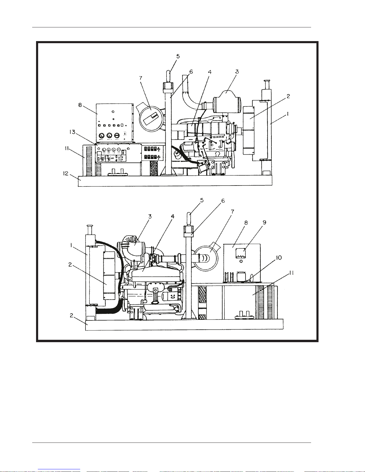
1. Radiator 8. Generator Control Box 15. Actuator, Governor
2. Fan Guard 9. Control Box, Governor 16. Lube Oil Pressure Switch
3. Muffler & Exhause Pipe 10. Power Module Panel 17. Lube Oil Pressure Sensor
4. Diesel Engine 11. Generator Assembly 18. High Engine Temperature
5. Lifting Eye 12. Frame Switch
6. Lifting Yoke 13. Engine Control Panel 19. Water Temperature Sensor
7. Air Cleaner 14. Output Terminal Panel
1-1 September 30/89 Revised
Page 8
Generator Set Components
Figure 3
Page 27
(3) Engine protective devices
(a) High coolant temperature switch
OM-2029
A high coolant temperature switch
the coolant temperature. If the coolant temperature reaches 210 degrees F
this normally closed switch opens and actuates the fuel valve solenoid which shuts down the
engine.
(b) Oil pressure switch
A diaphragm-type switch monitors the pressure in the lubricating oil system. It is mounted in
the side of the cylinder block
(69 kPa)
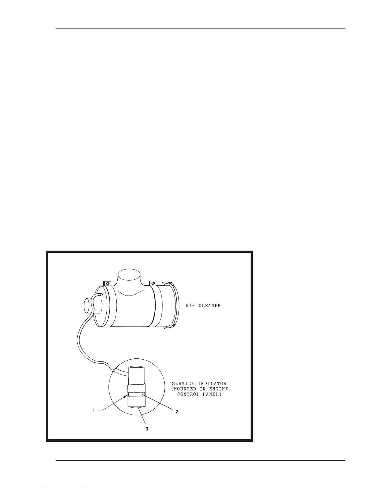
(4) Air cleaner
The diesel-engine air cleaner
tor and a service indicator. The indicator functions to signal the operator when the cartridgeneeds
changing. A red cylindrical “flag”
when air pressure within the air cleaner housing drops below the outside air pressure. As the cartridge becomes loaded with dirt and air pressure withinthe cleaner lessens, the “flag” gradually
rises higher in the glass viewing chamber. When the “flag” reaches the top of the chamber, it
locks in that position to warn the operator that the cartridge must be changed. The “flag” is reset
(unlocked)
, this switch opens and actuates the fuel valve solenoid which shuts down the engine.
(Fig. 4)
by pushing the reset button
(18, Fig. 3)
is mounted at the rear of the engine to monitor
(99 degrees C)
(16, Fig. 3)
(2)
is forced upward in a glass enclosed viewing chamber
. If the pressure in the lube oil system falls to 10 psi
is a dry-cartridge type. It is equipped with a moisture elimina-
(3)
located on the bottom of the indicator.
(1)
NOTE: The service indicator is mounted on the engine control panel and connected to the air cleaner
by a rubber hose. The indicator flag is visible only when the engine is running, or when the flag islocked
in WARNING position.
,
September 30/89 Revised 1-1
1. Viewing chamber
2. Indicating “flag”
3. Reset button
Air Cleaner and
ServiceIndicator
Figure 4
Page 9
Page 28
OM-2029
(5) Water Temperature Sender
The water temperature sender
actuates the temperature gage
(6) Oil Pressure Sender
The oil pressure sender
senses oil pressure and operates the oil puressure gage
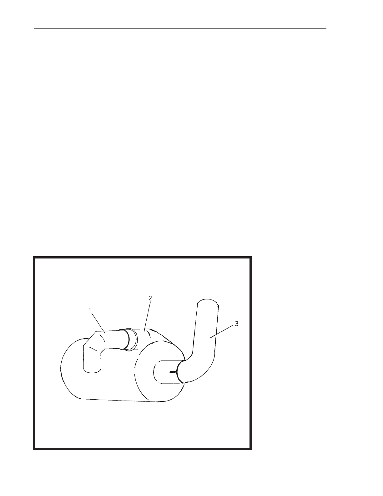
(7) Exhaust system
The exhaust system consists of a special noise reducing muffler
(1)
apipe
ward.
(8) Radiator
The radiator
ing. Refer to Section 2-1, Para. 6, G, for servicing procedure.
to a conventional exhaust manifold. The tail pipe
(1, Fig. 3)
is a one-piece item designed for long periods of operation without servic-
(19, Fig. 3)
(5, Fig. 9)
(17, Fig. 3)
is mounted at the top rear of the engine. This device
on the engine control panel.
is mounted at the right lower rear of the engine. This device
(4, Fig. 9)
(3)
on the engine control panel.
(2, Fig. 5)
directs exhaust and noise down-
which is connected by
1-1 September 30/89 Revised
Page 10
1. Pipe, manifoldto-muffler
2. Muffler
3. Exhaust Pipe
Exhaust System
Figure 5
Page 29
OM-2029
D. Generator
The 400-Hz generator is a brushless, revolving field, three-phase, alternating current type. The rotor
assembly is mounted by two, permanently lubricated, sealed, ball bearings. The front bearing is supported by the fan housing; the rear bearing is mounted in the exciter housing. Both of these housings
are attached to the main generator stator housing. The front end of the rotor shaft extends forward beyond the rear bearing and into the exciter stator housing. The exciter rotor is mounted on this shaft extension with a Woodruff key and is securedby a washer and 1/2"-13thd, cap screw. A rectifier with
six diodes is mounted on the exciter rotor and converts exciter AC output to DC for excitation of the
generator revolving fields. The exciter DC output to the generator fields, and consequently the generator output, is controlled by the amount of DC voltage supplied to exciter fields by the static voltage
regulator. A centrifugal, radial-blade fan which is part of the hub and coupling assembly, draws cooling air over all internal windings. Air enters at the exciter end and is discharged at the drive end. The
complete generator is bolted to the engine flywheel housing.
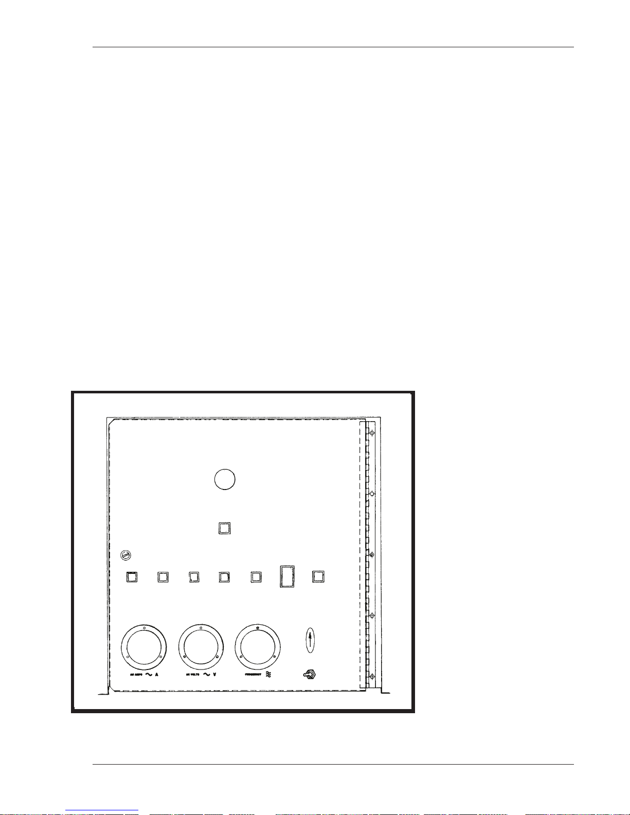
E. Control Box Assembly
The control box
generator controls and monitoring equipment. Switches, meters, indicator lights, and circuit breakers
which control and help to monitor the generator are all mounted on the front panel of the c ontrol box.
This panel is hinged on the right side, and can swing open for access to the interior panel where the
generator PC board assemblies and relays are mounted. A shielded, instrument panel light is
mounted near the top of the control box front panel, to illuminate controls and instruments on the
panel.
(Fig. 6)
is a sheet metal enclosure which houses and provides mounting facilities for
Control Box
Figure 6
September 30/89 Revised 1-1
Page 11
Page 30

OM-2029
(1) Generator Control Box Front Panel Components
(a) Generator output monitors (meters)
• Refer to Figure 7. The generatoroutput is monitored by three instruments; a frequency meter
(10),
a voltmeter
type, and indicates frequency of generator ouput alternating current in the range of 380 to
420 Hz
phase-to-neutral
the meter selector switch
scribed below. The voltmeter has a 3-1/2-inch face and the scale is graduated 0 to 300V.
The ammeter is also 3-1/2-inch size and is graduated 0 to 500A. Amperage value in each
of the three phases may be read on the ammeter by selecting the desired phase with
switch
of infinite ratio, which will operate the ammeter movement without damage. The ammeter
dial scale is graduated and numbered so that the pointer will indicate true load current
value rather than the meter movement current.
(b) Meter and line switches
• These switches provide a means of selecting and determining which phase of voltage and
current is indicated on the voltmeter and ammeter and whether the voltage is line-to-neutral
or line-to-line. The meter switch
the panel is marked and lettered to indicate the three functional positions of the meter
switch. When the knob is pointing straight down, the switch is OFF. The line switch
two-position, toggle switch used to select either line-to-neutral or line-to-line voltage to the
voltmeter. The nameplate is also marked to indicate the position of this switch.
(cycles per second).
(7).
Three ammeter current transformers lower ouput load current to a lesser value,
(12),
andanammeter
The voltmeter indicates generator ouput voltage in each
(A-N, B-N and C-N)
(7)
and the line selector switch
(7)
(13).
The frequency meter is a resonant-reed
or phase-to-phase
is a four-position, rotary type. Around the switch knob,
(A-B, B-C and C-A)
(8).
These switches will be de-
as selected by
(8)
is a
(c) Indicating lights
• The function of these lights
mal condition of overvoltage, underfrequency, etc., which caused the protective monitor
system to function. Each of the five lights is connected to an actuating circuit within the
memory and time delay module. When one of the circuits is activated, it turns on the applicable indicating light. The light will remain on until the reset switch
in the indicating lights may be tested by pressing switch
(d) Load contactor circuit breaker
• This 2-ampere circuit breaker
(e) Protective system circuit breaker
• This 2-ampere circuit breaker
overload.
(9, 11, 14, 15 and 16)
is to indicate, to the operator, the abnor-
(5)
is pushed. All lamps
(5).
(4)
protects the load contactors against overload.
(6)
protects the 12VDC protective monitor circuit against
1-1 September 30/89 Revised
Page 12
Page 31

OM-2029
1. Control box 10. Frequency meter
2. Control panel 11. Underfrequencyindicating light
3. Panel light 12. Generator voltmeter
4. Load contactor circuit breaker (2Amp) 13. Generator ammeter
5. Test-reset switch 14. Overload indicating light
6. Protective system circuit breaker 15. Undervoltage indicating light
7. Meter selector switch 16. Overvoltage indicating light
8. Line switch 17. Panel latch
9. Overfrequency indicating light
Generator Control Box Front Panel Components
September 30/89 Revised 1-1
Figure 7
Page 13
Page 32

OM-2029
(2) Generator Control Box Interior Components (Figure 8)
Mounted on the generator contrl box interior are electrical and safety devices designed to protect
the aircraft electrical system against damage which could result from overvoltage, undervoltage,
overfrequency, or underfrequency. Also on this panel are devices for the protection and control of
the generator output electrical system.
(a) Sensing modules
The voltage sensing module
generator output leads between the generator and the load contactor. These solid-state modules sense any abnormal condition of voltage or frequency and signal the solid-state circuitry
of the memory and time delay module
to the aircraft. Trip values are adjustable, however, adjustments should be made ONLY under
laboratory conditions.
Solid-state overload signaling devices
panel assembly)
similar to the voltage and frequency sensing modules.
Trip values for protective circuits are as follows:
• OVERVOLTAGE trips at 130V to 134V
• UNDERVOLTAGE trips at 102V or below
• OVERFREQUENCY trips at 415Hz to 425Hz
• UNDERFREQUENCY trips at 390Hz to 395Hz
• UNDERVOLTAGE time delay
• OVERLOAD circuit trips at any value over 125% rated load capacity
(b) Memory and time delay module
The memory and time delay module
It is a solid-state device with a hermetically-sealed, reed-type relay. The printed circuit board
or “card” includes five memory circuits and a time delay circuit. Each circuit is connected to a
corresponding sensing circuit in the sensing modules
connected to the module relay coil, and any one of the circuits can energize the coil to open
the relay contacts. Thus, when a sensing device energizes any one of the module circuits, the
module relay is also energized to break the load contactor holding circuit and allow the load
contactor to open. All circuits, except the undervoltagecircuit, function immediately to open
the load contactor. A time delay system is designed into the undervoltage circuit to prevent
nuisance opening of the contactor under conditions of momentary undervoltagein the generator output. An undervoltage condition which continues uninterrupted for a period of 4 to 12
seconds
five circuits is connected to a corresponding indicating light
turned on when a fault occurs.
(adjustable)
are also connected to the protective monitor module and perform a function
(17)
and frequency sensing module
(19)
to open the load contactor and disconnect output
(18)
are connected to the
(one for each output, and located on the power module
(adjustable)
(19)
is sometimes called the protective monitor module.
(17 and 18)
will cause the time delay circuit to open the load contactor. Each of the
. All memory circuits are
(9, 11, 14, 15 and 16)
which is
The module relay will remain energized
switch
mal, CLOSED position.
1-1 July 27/90 Revised
Page 14
(5)
is pushed to break the module 12-V DC circuit, and allow the relay to return to nor-
(OPEN)
and the light will remain ON until the reset
Page 33

OM-2029
(c) Plug-interlock relays
Each ouput of the generator has a plug interlock relay. For either output, the function of the
plug interlock relay is to cause its output load contactor to open in the event the cable plug
connector becomes accidentally disconnected from the aircraft during power delivery, or if an
attempt is made to deliver power when the output cable is not connected to the aircraft.
Twenty-eight-volt, direct current for operation of the relay is supplied from the aircraft either
through an on-board transformer-rectifier, or from a twenty-eight-volt, electrical system. Connection from the aircraft to the interlock relay is made through terminals E and F on the output
cable plug connector.
(d) Test-bank switches
Each ouput of the generator has a test-bank switch. For either output, the function of this single-pole-single-throw switch is to provide a means of by-passing the output’s interlock relay
when supplying power to a load bank or to an aircraft not equipped with a plug interlock system.
(e) Resistor
Each output of the generator has a 100-ohm, 25-watt resistor connectedin series with the
plug interlock relay to protect the relay in the event that phase C contacts in the load contactor should fail to close when the generator ON switch is operated. For outputs No. 1 and No.
2, the resistors are items 22 and 20, respectively.
A variable 20-ohm, 100-watt, ballast resistor
citer DC field and thus determine the voltage range through which the regulator can control
generator output voltage.
(f) Fuse-interlock relay
The function of the fuse-interlock relay
and remove the load in case of a tripped circuit breaker in the protective relay coil circuit.
(g) Auxiliary underfrequency relay
The function of the auxiliary underfrequency relay
deenergization relay and disconnectthe voltage regulator anytime generator frequency drops
to 380 Hz or below. This protects the voltage regulator and ballast resistor
load which could be caused by very high voltage regulator output in its attempt to maintain
voltage when the generator is operating at a speed which cannot produce n ormal voltage output.
(21)
is connected in series in the generator ex-
(6)
is to interrupt the load contactor holding coil circuit
(7)
is to automatically open the excitation-
(24)
against over-
NOTE: If the auxiliary underfrequency relay is tripped, it will be necessary to momentarily place engine
operating mode switch in BUILD-UP-VOLTAGE position to restore generator voltage.
(h) Regulated-diagnostic switch
When the regulated-diagnostic switch
voltage is regulated by the voltage regulator or 115/200 VAC output to an aircraft. When this
switch is placed in the DIAGNOSTIC position, battery voltage
erator exciter with the engine running at rated RPM, in order to check the operation of the
generator set. By applying this DC voltage to the exciter and observing generator output voltage, it can be determined if a particular power output malfunction is caused by a defective
generator or by a defective voltage regulator.
(26)
is in the REGULATED position, generator output
(12VDC)
is applied to the gen-
(j) Excitation-deenergization relay
The purpose of this relay
field only when the engine speed is being controlled by the electric governor.
July 27/90 Revised 1-1
(5)
is to allow automatic excitation to be connected to the exciter
Page 15
Page 34

OM-2029
1. Control box rear inside panel 11. Sensing/pre-amplifier assembly
2. Protective system interlock relay of voltage regulator
No. 2 output 12.Control box right side panel
3. Plug interlock relay, No. 2 output 13. Control box bottom inside panel
4. Governor idle speed relay 14. Terminal blocks
5. Excitation deenergization relay 15. Generator main overload relay
6. Protective system interlock relay, 16. Control box left side panel
No. 1 output 17. Over-undervoltage relay
7. Auxiliary underfrequency relay 18. Over-underfrequency relay
8. Plug interlock relay, No. 1 output 19. Memory & time delay relay
9. Voltage regulator (Magnetic- 20. No. 2 contactor hold circuit resistor
Amplifier type shown) 21. Ballast resistor, 20-ohm, 100-watt
10. Line drop compensator assembly 22. No. 1 contactor hold circuit resistor
of voltage regulator
Generator Control Box Interior Components
1-1 July 27/90 Revised
Page 16
(Sheet 1 of 2)
Figure 8
Page 35

OM-2029
(k) Voltage Regulator
The voltage regulator used on any Series 6906 generator set is located inside the control
box, and is accessible by swinging open the front panelof the control box.
Specification 6906-1 and Specification 6906-2 generator sets are equippedwith a solid state
voltage regulator, Hobart Part No. 489812A. Information and instructions for this regulator
are contained in Hobart regulator manual OM2020, found in Chapter 6 of this generator set
manual (OM-2029).
Generator set Specifications 6906-3, -4, -5, and -6 are equipped with a magnetic amplifier
type voltage regulator, Hobart Part No. 281407. Information and instructions for this regulator
are contained in Hobart regulator manual TM-759, found in Chapter 6 of this generator set
manual (OM-2029)
23. Switch bracket (behind generator control panel)
24. Test bank/aircraft switch No.1 output
25. Test bank/aircraft switch No. 2 output
26. Regulated/diagnostic switch
27. Idle speed adjustment potentiometer
July 27/90 Revised 1-1
Generator Control Box Interior Components
(Sheet 2 of 2)
Figure 8
Page 17
Page 36

OM-2029
F. Engine Control Panel (See Fig. 9)
The engine control panel is mounted directly below the control box. In addition to engine controls
and instruments, generator output controls are mounted here. A plexiglass window in the canopy
rear door, slants outward at the bottom to form an opening for access to controls when the door is
closed.
(1) Engine instruments
Engine operation is monitored by an ammeter
pressure gage
(a) Ammeter
• The ammeter
system. Its graduated range is from -60 A through 0 A, to +60 A.
(b) Temperature gage
• The temperature gage
temperature sender
engine coolant temperature in the range of 100F to 220F.
(c) Oil pressure gage and oil pressure switch
• The oil pressure gage
erated by an oil pressure sender
• The switch connects 12-V DC power to the engine control system and to the generator 12V DC control system when the engine is running.
(d) Hourmeter
• The hourmeter
measures and records engine running time and will record up to 9999.9 hours on five revolving drums. The hourmeter operates only when the engine is running and the oil pressure switch is closed.
(2) Engine and generator controls
(4)
. An hourmeter
(3)
indicates the direction and value of current flow in the 12-V DC electrical
(5)
(19, Fig. 3)
(4)
(6)
records engine operating time.
indicates the engine coolant temperature and is actuated by a
mounted on the engine’s water jacket. The gage indicates
displays the pressure in the engine’s lubrication system. It is op-
(17, Fig. 3)
(6)
is electrically driven from the 12-V DC battery system. The hourmeter
(3)
, a coolant temperature gage
mounted on the engine block.
(5)
, and an oil
(a) Engine-generator control switch
• The engine-generator control switch
idle” switch)
VOLTAGE, and will automatically reposition to GENERATE position when released. In
BUILD-UP-VOLTS position it performs a dual function. First, it supplies power to the gover-
nor control box, which allows the engine to operate at normal governed speed; second, it
momentarily supplies current for closing the excitation-deenergization relay contacts, to
make three-phase, 115-V AC power available to the voltage regulator, or to the manual
voltage control circuit for excitation of the generator exciter. In GENERATE position, power
is maintained to the governor control box and to the excitation relay. When the switch is
placed in IDLE position, power is disconnected so that the engine returns to idle speed and
the exciter field is deenergized.
1-1 September 30/89 Revised
Page 18
is a three-position toggle type. It is spring-loaded in one position, BUILD-UP-
(15) (also identified as the “build-up-voltage, generate,
Page 37

OM-2029
(b) Contactor control switches
• This is another three-position, toggle switch identical to the engine-generator control
switch. When placed in the spring loaded CLOSE position, it provides 115-V AC power directly to a rectifier which supplies DC power for closing the load contactor. When released
it returns to the normal ON position and continues to provide power to the rectifier, but in
this switch position, AC power must pass through the plug interlock and fuse interlock relays. In OFF position the switch opens the AC circuit to the rectifier, thereby cutting off the
source of DC power to the contactor coil which allows the contactor to open.
(c) Instrument light and switch
• A shielded, instrument panel light
controlled by a rocker switch
and clearance lights on the canopy of the generator set.
(d) Engine starting circuit
• The pushbutton start switch
for closing an auxiliary solenoid switch. The auxiliary switch then connects power to the
starter solenoid which functions to engage the starter gear with the flywheel ring gear and
apply power to the starter motor to crank the engine. The auxiliary solenoid switch is necessary because the start pushbutton switch is not capable of carrying the high amperage flow
to the starter solenoid which would result if the starter gear and ring gear should fail to engage. The permissive rocker switch
the down
(e) Indicating lights
• A green indicating light
tive system. The light operates only when the engine is running and fuel pressure is sufficiently high to close a fuel pressure switch. The purpose of the pressure switch is to
deactivate the protective circuit when the engine is stopped and prevent battery discharge.
• Two other green indicating lights
is CLOSED and power is available at the generator output terminal panel
(f) Engine circuit breaker
• A 10-ampere circuit breaker
nating light circuit, and 12VDC system in the main generator protective system.
(STOP)
position.
(13)
(2)
is mounted at the left side of the control panel. It is
(17)
, which also controls instrument lights on the control box
(16)
and permissive rocker switch
(14)
also stops the engine when the toggle is placed in
glows to indicate that power is available to the engine protec-
(9 and 10)
(8)
protects the 12VDC engine control circuit, hourmeter, illumi-
glow when the generator output load contactor
(14)
serve to connect power
(g) Air cleaner indicator
• The air cleaner indicator
function was explained in Para. 7, C,
September 30/89 Revised 1-1
(18)
is mounted on the engine control panel for easy viewing. Its
(4) (see Fig. 4).
Page 19
Page 38

OM-2029
1. Engine control panel 10. Indicator, No. 2 load contactor
2. Panel light 11. Switch, No. 1 load contactor
3. Engine ammeter 12. Switch, No. 2 load contactor
4. Oil pressure gage 13. Engine ON indicator light
5. Water temperature gage 14. Engine START-RUN-STOP switch
6. Hourmeter 15. Build-up-voltage/generate/idle switch
7. Terminal block 16. Engine start switch
8. Circuit breaker, engine circuit 17. Switch, clearance/panel lights
9.Indicator, No. 1 load contactor 18. Air filter service indicator
Engine Control Panel
Figure 9
H. Power Module Panel Assembly
The power module panel assembly
cated at the right rear of the machine behind the control box. The power module panel is accessible by opening the left rear door on the canopy. The panel assembly provides sensing and
overload protection for the output circuit and provides a means of connecting and disconnecting
generator output to and from the load
(Fig. 10)
sometimes referred to as the “contactor panel”, is lo-
(aircraft).
1-1 September 30/89 Revised
Page 20
Page 39

(1) Load contactor
OM-2029
Two load contactors are used in this unit. One contactor
the other contactor
Each load contactor is a sealed unit which contains a magnetic operating coil and four sets of
contacts. The three larger contacts conduct three-phase AC generator output. A smaller contact set is connected in the protective monitor circuit and supplies 12VDC power used by
sensing relays to signal the protective monitor when a fault occurs. Three-phase, 400-Hz generator output power is conducted to and through the load contactor by cables which also pass
through four sets of current transformers
NOTE
: This contactor may be replaced by the old style contactor used in previous 60-KVA machines.
(9)
serves output circuit No. 2.
(3, 5, 16, and 18) .
(8)
serves output circuit No. 1, and
This note is for the benefit of those users who may have old style contactors Part number 75GH-566
(Hartman No. A-874C) in stock.
(2) Current transformers
(a) Ammeter current transformers
• Three current transformers
tio
(500-A to 5-A)
ter dial scale is graduated and numbered so that the ammeter pointer will indicate the true
load current value rather than the meter movement current.
(b) Line-drop current transformers
• The three line-drop current transformers
tect the magnitude and power factor of current flowing from generator to load. They feed a
signal to the voltage regulator which interprets the signal and alters the exciter field current
as required to maintain a constant predetermined voltage at the load
which will operate the ammeter movement without damage. The amme-
(16)
lower the output load current to a lesser value of definite ra-
(18),
in conjunction with burden resistors
(see Voltage Regula-
(17),
tor Manuals No. TM-759 for a Mag-Amp type or OM-2020 for a Solid-State type regulator).
de-
(c) Overload current transformers
• Each output circuit has three overload current transformers,
item 3 for No. 2 output)
rent in each of the three output phases, and supply a reduced value current signal to the
overload module which serves the output circuit.
(3) Rectifiers
A diode-bridge rectifier
an converts it to a pulsating, direct current for energization of the load contactor holding coil
only. This DC coil-holding circuit is controlled indirectly be controlling the 400-Hz AC to the
rectifier. The ground circuit for the rectifier’s AC supply must pass through the relay contacts
in the protective monitor module to ground cable N. Therefore, any time a protective device
functions to open the protective monitor relay, the rectifier’s AC circuit is opened. No DC is
then available for the load contactor holding coil, hence, the load contactor opens.
which, in conjunction with burden resistors monitor output load cur-
(6 and 7)
receives 400-Hz AC from phase C of the generator output
(item 5 for No. 1 output, or
September 30/89 Revised 1-1
Page 21
Page 40

OM-2029
(4) Overload module
Each output of the generator set has an overload module
for No. 2 output).
from a set of overload current transformers
and to send a signal to the protective monitor module when an overload condition exists in
any generator output phase. A pull-apart electrical connector is mounted on the overload module to provide quick-disconnect facilities for all wiring to a module. Each overload module is
equipped with a hermetically-sealed, reed-type relay. Relay contacts are normally open. The
solid-state circuitry is designed to close relay contacts when output current in ANY phase
reaches 125% of normal rated output capacity. The closed relay sends a signal to the protective monitor. This signal “gates” the overload SCR
tive monitor and interrupts the load contactor holding circuit, allowing the load contactor to
open.
The following is a list of overload module characteristics:
NOTE
:The overload protective system will function when any phase carries 123% to127% of rated load.
• At 125% load the module will function in 5 minutes.
• At 150% load the module will function in 16 seconds.
• At 200% load the module will function in 4 seconds.
NOTE
: All times are plus or minus 25% and are nonadjustable.
(5) Terminal boards
Two terminal boards
Each overload module is a solid-state device designed to interpret a signal
(item 5 for No. 1 output, or item 5 for No. 2 output)
(silicone-controlled rectifier)
(7)
provide connection facilities for small leads.
(item 13 for No. 1 output, or item 14
in the protec-
1-1 September 30/89 Revised
Page 22
Page 41

OM-2029
1. Power module panel 10. Rectifier, No. 1 contactor
2. Overload resistors, 25-watt, No. 1 output 11. Rectifier, No. 2 contactor
3. Overload transformers, No. 2 output 12. Capacitors, 0.1 mfd, 500-V
4. Overload resistors, 25-watt, No. 2 output 13. No. 1 overload PC module
5. Overload transformers, No. 1 output 14. No. 2 overload PC module
6. Blocking diodes 15. Connector socket housings
7. Terminal strips 16. Ammeter current transformers
8. No. 1 load contactor 17. Resistors, 50-ohm, 25-watt
9. No. 2 load contactor 18. Line-drop transformers
September 30/89 Revised 1-1
Power Module Panel Assembly
Figure 10
Page 23
Page 42

OM-2029
Output Terminal Panel
Figure 11
1-1 September 30/89 Revised
Page 24
Page 43

SECTION 2. PREPARATION FOR USE, STORAGE, OR SHIPPING
1. Preparation for Use
A. General
These instructions are based on the assumption that the unit is properly installed and that all necessary fuel and electrical connections have been made. Generator sets for stationary mounting are installed by the customer. Other generator sets, when ordered with truck or trailer, are mounted at the
Hobart factory and are shipped in running condition and ready for operation after inspection and
check.
WARNING: IMPROPER OPERATION CAN KILL, INJURE, OR CAUSE DAMAGE! READ AND UNDERSTAND OPERATING INSTRUCTIONS IN SECTION 13 BEFORE OPERATING THE UNIT.
B. Inspection/Check
Inspect the unit thoroughly prior to operation.
OM-2029
(1) Remove blocking, banding, ties, and other securing material.
(2) Inspect exterior for shipping damage such broken lights, damaged sheet metal, etc.
(3) Open all canopy doors and inspect interior for foreign material such as rags, tools, shipping pa-
pers, etc.
(4) Check fuel, coolant, and oil hoses and connections for visible leaks. Visually inspect the compart-
ment floor and ground surface under the unit for signs of leakage. If leaks are found, correct by tightening hose clamps, tube fittings, etc., as required.
(5) Check the following for sufficient quantity:
(a) Fuel
Turn ON panel lights to energize fuel gage when engine is stopped.
(b) Engine coolant
The radiator cap is accessible by opening the hinged access cover on the front canopy housing.
Coolant level should be approximately one inch below the filler neck. Allow a capacity for coolant
expansion.
CAUTION: BE SURE THE COOLING SYSTEM ANTIFREEZE SOLUTION IS ADEQUATE TO PROTECT BELOW LOWEST TEMPERATURE EXPECTED.
NOTE: For antifreeze protection, use a solution of 50% permanent antifreeze (Ethylene glycol) and 50%
clean water.
(c) Engine lubricating oil
Oil level should be at “FULL” mark on oil level gage rod. See the Perkins Shop Manual for oil recommendations.
September 30/89 Revised 1-2
Page 1
Page 44

OM-2029
(6) Check air cleaner
The air cleaner
other material covering the air inlet area.
C. Installing Output Cables
Units are generally shipped without generator set-to-aircraft cables.
(1) Three-phase, AC output cable assembly installation
The AC output terminal panel access cover is located on the right side, just to the right of the engine control panel
(a) Remove output terminal panel access cover.
(b) Loosen cable horn clamps and and insert the looseends of the cable assemblies through the
cable horns. Route to output terminal panel.
(Sect. 1-1, Fig. 3, item 7)
(see Fig. 1).
is a “dry” type. Be sure there are no papers, tapes, or
NOTE: Conductor size recommended for AC output is 2/0 size. Use No. 12 size for control (E and F
terminals).Largecables(A,B,C,N)shouldbeequippedwithterminalshavingat least a 3/8-inch diameter
mounting hole. Mounting hole in small leads (E and F) should be at least 1/4-inch diameter.
(c) Each terminal stud is identified by an identification plate. Each cable should be identified by a
band-type marker. Connect cable “A” to terminal “A”, “B” to “B”, etc. Connect one cable assembly
to the upper row of terminals, and connect the other cable assembly to the lower row of terminals.
(d) Tighten clamp screws securely, but avoid damage to cable insulation.
(e) Install terminal panel access cover which was removed in step (a) above.
1-2 September 30/89 Revised
Page 2
AC Output Terminal Panel
Figure 1
Page 45

2. Preparation for Storage
When a generator set is to be stored or removed from operation, special precautions should be taken to
protect the internal and external parts from rust, corrosion, and gumming in the engine fuel system.
A. General
(1) The unit should be prepared for storage as soon as possible after being removed from service.
(2) The unit should be stored in a building which is dry and which may be heated during winter
months.
(3) Moisture absorbing chemicals are available for use where excessive dampness is a problem, how-
ever the unit must be completely packaged and sealed if moisture absorbing chemicals are to be effective.
B. Temporary Storage
When storing the unit for 30 days or less, prepare as follows:
(1) Lubricate the unit completely in accordance with instructions in Sect. 2-1. This will include chang-
ing engine oil, and all filter elements.
OM-2029
(2) Start the engine and operate for about two minutes so that all internal engine components will be
coated with new oil.
NOTE: Do not drain the fuel system or crankcase after this run.
(3) Make certain the cooling system antifreeze solution is adequate to protect below the lowest temperatures expected during the storage period. See 2-1; Para. 6, D. Be sure the solution is thoroughly
mixed.
(4) Clean the exterior of the engine with fuel oil. Dry with clean rags and compressed air.
(5) Seal all engine openings. Use a waterproof, vaporproof material which is strong enough to resist
puncture damage from air pressures.
C. Long Time Storage (Over 30 Days)
(1) The unit may be stored for long periods with no special preparation if it is possible to operate the
engineonceeachweek.
(a) Make certain the cooling system is adequately protected.
(b) Start the engine and operate at a fast idle
reached at least 140 deg F.
(800 to 1000 RPM)
until coolant temperature has
WARNING: MAKE CERTAIN OF ADEQUATE VENTILATION BEFORE STARTING THE ENGINE.
(c) Operate normal operating controls.
(2) If weekly operation is not possible, prepare and protect the engine in accordance with instructions
in John Deere Operator’s Manual.
(3) To protect the generator and other electrical components, the complete unit should be packaged,
using moisture proof packaging and sealing material. Place containers of moisture absorbing chemicals, such as silica-gel, in the unit before packaging.
September 30/89 Revised 1-2
Page 3
Page 46

OM-2029
This page intentionally left blank.
1-2 September 30/89 Revised
Page 4
Page 47

SECTION 3. OPERATION
1.General
This section contains information and instructions for the safe and efficient operation of the equipment.
Operating instructions are presented in step-by-step sequence of procedures to be followed in supplying
400-Hz power to an aircraft.
WARNING: IMPROPER OPERATION CAN KILL! EAR PROTECTION EQUIPMENT MAY BE NECESSARY WHEN WORKING IN CLOSE PROXIMITY TO
THIS EQUIPMENT. READ AND FOLLOW ALL OF THE OPERATING INSTRUCTIONS BEFORE ATTEMPTING TO OPERATE THE EQUIPMENT.
2. Operating the Generator Set
A. Pre-start Inspection
OM-2029
(1) Open the fuel shut-off valve.
(2) Provide 12-V DC power to the engine starting system.
(3) Check the engine and generator compartments and remove rags or other foreign materials.
B. Normal Engine Starting Procedures
Engine starting procedures are outlined below. Engine operating controls and monitoring instruments
are illustrated in Fig. 1.
(1) If illumination is required, place light switch
NOTE: This switch must be ON to check fuel when engine is stopped.
(2) Hold engine start switch
(24)
to crank engine. When engine starts, release pushbutton. Continue to hold engine start switch
(22)
in position until oil pressure gage
(3) Check ammeter
(4) Check oil gage
(5) Place engine generator control switch
(15)
(27).
(22, Fig. 1)
for charge reading.
in START position momentarily. Push engine start pushbutton
(27)
(25)
in ON position.
reads at least 20 PSI pressure. Release switch
(23)
in IDLE position.
(22).
September 30/89 Revised 1-3
Page 1
Page 48

OM-2029
1. Panel light 15. Engine ammeter
2. Load contactor circuit breaker (2-A) 16. Engine circuit breaker (10-A)
3. Test-reset switch 17. Indicator, No. 1 load contactor
4. Protective system circuit breaker 18. Switch, No. 1 load contactor
5. Meter selector switch 19. Indicator, No. 2 load contactor
6. Line switch 20. Switch, No. 2 load contactor
7. Generator ammeter 21. Engine ON indicator light
8. Generator voltmeter 22. Engine START-RUN-STOP switch
9. Frequency meter 23. Build-up-voltage/generate/idle switch
10. Overvoltage indicating light 24. Engine start switch
11. Undervoltage indicating light 25. Switch, clearance/panel lights
12. Overload indicating light 26. Air filter service indicator
13. Underfrequency indicating light 27. Oil pressure gage
14. Overfrequency indicating light 28. Water temerature gage
29. Hourmeter
Operating Controls and Instruments
Figure 1 (Sheet 1 of 2)
1-3 September 30/89 Revised
Page 2
Page 49

OM-2029
30. Automatic voltage control rheostat 35. Damping circuit GAIN potentiometer
31. Foot compensation potentiometer 36. Test bank/aircraft switch, No. 1 output
32. Line-drop compensation ON/OFF switch 37. Test bank/aircraft switch, No. 2 output
33. Cable size potentiometer 38. Regulated/diagnostic switch
34. Damping circuit RATE potentiometer 39. Idle speed adjustment potentiometer
July 27/90 Revised 1-3
Operating Controls and Instruments
Figure 1 (Sheet 2 of 2)
Page 3
Page 50

OM-2029
C. Cold Weather Engine Starting Procedures
A cold weather starting-aid kit
low 50 degree F. To start the engine, using the starting aid, proceed as follows:
(1) Position switches and controls as instructed in steps
Starting Procedures, above.
(2) Prepare starting aid for use. The starting aid is shipped in a safe condition and is not operable until
assembled. Assemble as follows:
(Fig. 2)
is provided to assist in starting the engine at temperatures be-
(1)
and
(3),
paragraph B, Normal Engine
WARNING: FIRES, FUMES, AND FLYING PARTS CAN KILL OR INJURE!
STARTING FLUID IS EXTREMELY FLAMMABLE. IT IS UNDER PRESSURE.
USE CAUTION WHEN HANDLING. AVOID CONTACT WITH SKIN AND AVOID
BREATHING VAPOR.
(a) Loosen clamp screws
(3)
tive cap
(b) Use bottle opener to remove cylinder cap
(c) Slide the cylinder
aid is now ready to use.
and plug
(1, Fig. 2)
(4).
(2)
downward and thread into the valve
and slide the cylinder
(3).
Unscrew and remove plug
(2)
upward sufficiently to remove protec-
(4).
(5).
Tighten securely. The starting
1-3 September 30/89 Revised
Page 4
Cold Weather Starting Aid (Optional)
Figure 2
Page 51

(3) Cold weather starting procedures are exactly the same as for normal starting except:
(a) Before cranking the engine, pull the starting aid control OUT to the fullextent of its travel. Hold
for 2 to 3 seconds.
(This allows the starting aid valve chamber to fill with pressurized ethyl ether.)
OM-2029
(b) Push the control IN.
(c) Push starter switch
(d) Follow normal starting procedures and CAUTIONS above [steps
(e) In extremely cold weather it may be necessary to repeat steps
CAUTION: USE STARTING AID ONLY FOR STARTING. DO NOT OPERATE WHILE ENGINE IS
RUNNING.
(This step sprays starting fluid into the engine intake manifold.)
(24)
to crank engine.
(5)
(a)
through
and
(b)
(7),
above.
para. 2, B].
WARNING: DO NOT “FLOOD” THE ENGINE WITH STARTING FLUID. A SERIOUS EXPLOSION COULD RESULT.
D. Preparation for Power Delivery (Normal Automatic Voltage Control)
The following are power delivery preparation procedures to be followed after the engine is started.
(1) Check and position switches and controls.
(a) Open front door of the generatorcontrol box and check the position of the REGULATED/DI-
(38).
AGNOSTIC switch
(b) Place test bank switch
with 28.5VDC interlock relay system.
front door of generator control box.
(c) Meter selector switch
Make certain that this switch is in the REGULATED position.
(36)
in AIRCRAFT position if the aircraft being serviced is equipped
(If not, place in TEST BANK position).
(5)
may be in any position except pointing straight DOWN.
Close and fasten
(2) Connect output cable plug connector to aircraft receptacle. Be sure connectors are mated fully
and securely.
E. Power Delivery
No. 1 Output Circuit
(1) Place engine-generator control switch
then allow it to position itself in GEN position. The electric governor will immediately increase engine
speed to 1714 RPM and maintain it.
(2) Observe generator instruments. Frequency meter
(8)
meter
(3) The final step in delivering power is closing the load contactor. When satisfactory frequency and
voltage values are indicated by the instruments, close No. 1 load contactor by momentarily placing
the load contactor control switch
light
the aircraft. As soon as the light glows, release the switch. It will automatically return to the center ON
position.
should indicate 115 V AC when line switch
(18)
(17)
should glow at once to indicate that the load contactor is closed and power is available at
(23, Fig. 1)
in the top
in BUILD-UP-VOLTAGE position momentarily,
(9, Fig. 1)
(6)
is in LINE-TO-NEUTRAL position.
(spring loaded),
should indicate exactly 400 Hz. Volt-
CLOSE position. The green indicating
July 27/90 Revised 1-3
Page 5
Page 52

OM-2029
NOTE: If the indicating light (17) should “go-out” as soon as the switch is released, and no fault lights
are ON, it indicates that 28.5-V DC holding current is not being supplied from the aircraft to the
plug-interlock relay. Correct the condition an again operate the load contactor control switch (18) as
above.
(4) It is recommended that the operator check output voltage and current in each of the three phases
(5)
early in the power delivery run. Use the meter switch
select line-to-line or line-to-neutral voltage. If the load is changing, it is good operating practice to observe the instruments until load conditions stabilize.
(5) A condition of overvoltage, undervoltage, underfrequency, overfrequency, or overload in the output circuit will automatically open the load contactor and turn on the applicable indicating light to signal the operator which of the above faults caused the protective monitor system to operate. After the
fault has been corrected, press the reset switch
tive relay system. Proceed with power delivery by operating the load contactor switch.
No. 2 Output Circuit
The procedure for operation of the No. 2 output circuit is exactly the same as for No. 1 circuit, except that the No. 2 contactor control switch
(19)
is observed. All other controls and procedures that were used for No. 1 output are used for
the No. 2 output.
(3)
(20)
to select the phase. Use the line switch
to turn off the indicating light and reset the protec-
is used and the No. 2 contactor indicator light
(6)
to
F. Discontinue Power Delivery
(s)
(1) Place load contactor switches in OFF position. Green light
cate that the load contactor has opened and power is no longer being delivered to the aircraft.
(2) Place engine-generator control switch
(3) Disconnect output cable from aircraft.
(23)
in IDLE position.
should go OFF immediately to indi-
WARNING: HIGH VOLTAGE - ELECTRIC SHOCK OR FIRE CAN KILL! NEVER
DISCONNECT THE OUTPUT CABLE WHILE POWER IS BEING DELIVERED.
K. Stopping the Engine
(1) Allow the engine to idle a few minutes before stopping, to permit cooling.
(2) To stop the engine, move the START-RUN-STOP switch
(22)
to the STOP
(down)
position.
3. Transformer-Rectifier Operation
(Optional Equipment on Specifications 6906-3, 6906-4, 6906-5 and 6906-6)
Transformer-Rectifier operating instructions are contained in its operating manual, however some generator set instructions are required here.
A. Direct Current Power Delivery
NOTE: If the customer adds a Transformer-Rectifier to a standard machine which was
with a T-R when it left the factory, he must remove the jumper lead which will be found on the small
terminal strip in the generator set voltage regulator. If your generator set has a factory installed T-R, the
jumper will have been removed.
(1) When delivering power from a T-R, prepare the generator set for DC power delivery the same as
for AC delivery, except do not connect AC output cable and do not close AC load contactor.
(2) For T-R operating instructions, see Hobart Manual No. OM-433.
1-3 July 27/90 Revised
Page 6
NOT
equipped
Page 53

OM-2029
Transformer-Rectifier
Figure 3
B. Simultaneous 28.5-V DC and 115-V AC Power Delivery
If both 28.5-V DC and 115-V AC must be delivered at the same time, the following rules and precau-
must be observed.
tions
(1) Place T-R current limiting switch in OFF position. This will eliminate the soft start feature of the T-
R, but will prevent AC voltage from dropping low enough to trip the AC load contactor.
(2) Line-drop compensation on the T-R must be REDUCED or turned DOWN completely to prevent
opening of the AC load contactor by an overvoltage condition. Readjust T-R line-drop compensation
so that AC voltage
(as indicated by the generator set voltmeter)
does not exceed 118-V AC when the
DC load is 500 Amperes. If higherDC voltage is needed, adjust T-R line-drop compensation as required.Observe AC voltage while making this adjustment to be certain that it does not go TOO HIGH
with DC load.
(3) During simultaneous, continuous operation, loads on either circuit are limited only by the capacities of their respective circuits, however, the combined loads should not exceed the rated capacity of
the generator set
(140 KVA or 112KW).
July 27/90 Revised 1-3
Page 7
Page 54

OM-2029
4. Trailer Operation (Optional)
A. Towing
Observe the following rules when towing the trailer.
(1) Be sure all output cables are disconnected and properly stowed.
(2) Be sure parking brake is released.
(3) Avoid turns which are shorter than the steering linkage will freely allow.
(4) Avoid dangerous speed and sudden turns.
B. Parking
Observe the following rules when parking the trailer.
(1) Apply parking brake before disconnecting tow vehicle.
(2) Always place drawbar in an upright, vertical position when trailer is parked.
1-3 September 30/89 Revised
Page 8
Page 55

CHAPTER 2. SERVICE
SECTION 1. MAINTENANCE
1. General
To make certain the generator set is always ready for operation, it must be inspected and maintained
regularly and systematically so that defects may be discovered and corrected before they result in serious
damage or failure of the equipment.
WARNING: ELECTRIC SHOCK, FLYING PARTS, OR FIRE CAN KILL OR INJURE! STOP OPERATION IMMEDIATELY IF A SERIOUS OR POSSIBLY DANGEROUS FAULT IS DISCOVERED.
2. Inspection
OM-2029
A periodic inspection should be established and maintained. A suggested inspection/check schedule is
provided in 2-2, Figure 1, however it may be modified as required to meet varying operating and environmental conditions. If the generator set is mounted on a tow tractor, it is suggested that inspections be coordinated.
3. Lubrication
A. General
Proper lubrication is one of the most important steps in good maintenance procedures. Proper lubrication means the use of correct lubricants and adherence to a proper time schedule. Frequency of lubrication and recommended lubricants are indicated in Figure 1.
B. Generator
The 400-Hz generator requires NO lubrication. The rotor is supported by two ball bearing assemblies
which are lubricated and sealed at the factory for lifetime, maintenance-free operation. It is suggested
that generator bearings be checked after 5000 hours of operation.
C. Generator Controls
Generator controls and instruments require no scheduled periodic lubrication. A few drops of oil may
be required on door hinges occasionally to insure free an quiet operation.
D. Engine
Although the engine and its accessories require no more attention than any other similar installation,
they still inherently require a major portion of the generatorset lubrication and maintenance. Recommendations regarding engine lubrication have been taken from the engine manufacturer’s “Operator’s
Manual” and incorporated here to make them more readily available to operators and maintenance
personnel.
September 30/89 Revised 2-1
Page 1
Page 56

OM-2029
(1) Lubrication schedule
(2) Oil specification
Time schedules indicated on the Lubrication Chart, Fig. 1, are approximate. They are based on
average operating conditions. It may be necessary to lubricatemore frequently under severe operating conditions such as: low engine temperatures, excessively heavy loads and high oil temperatures, or intermittent operation. However, time intervals should not exceed those indicated in the
chart without careful evaluation.
Oil recommended by the engine manufacturer is identified by a military specification number, MILL-2104B. Because of the substantial increase in additive concentration in some MIL-L-2104B oils
to meet service “MS” requirements, recommended oil is qualified still further by the following limitations
(a) Zinc, as zinc diorganodithiophosphate, between a minimum of 0.07 and a maximum of 0.10
percent by weight.
(b) Sulfated ash
tain only barium detergent-dispersants where 1.50 percent by weight is allowed.
Diesel lubricating oil specifications are discussed in the John Deere Diesel Handbook for Diesel
Engines.
(3) Oil viscosity
The use of an SAE-30 grade oil is recommended for year-round service.
To assist in engine starting during cold weather when SAE-30 oil is used, an optional ether start-
ing aid is available from Hobart Brothers Company. Multigrade oils are NOT recommended, and
should be considered only as a “last resort” to facilitate engine starting.
(4) Changing engine oil
Change engine lubricating oil following the instructions in the John Deere Engine Shop Manual
(Chapter 6).
(5) Changing engine oil filter
Change the oil filter following the instructions in the John Deere Engine Shop Manual (Chapter 6).
E. Starter
The starting motor is lubricated at assembly and should be relubricated only when the starter is removed from the engine or when disassembled.
(ASTM D-874)
Lube oil capacity for this engine is 18 quarts.
of 1.00 percent maximum by weight, except lubricants that con-
Remove pipe plugs on outside of motor and apply a few drops of light engine oil to the oil wicks.
2-1 September 30/89 Revised
Page 2
Page 57

ITEM MAINTENANCE REQUIRED
Lube Oil Check oil level daily or after every 10
hours of use. Change oil after 200 hours
or one month of use. Use heavy duty oil
such as SAE-30 (MIL-L-2104B). Engine lube
oil capacity: 18 quarts
Lube Oil Filter Change oil filter every 200 hours or 1
month of use.
Fuel Oil Filter Drain filter daily. Change filter element
every 600 hours or 4 months of use.
Starter Lubricate as needed, using heavy duty
engine oil such as SAE-30 (MIL-L-2104B).
Lubricate only when starter is removed
from engine.
OM-2029
Coolant Check coolant level daily. Service and
maintain coolant system according to para.
6. Engine coolant capacity: 12.44 gallons
Air Cleaner Change air cleaner cartridge as required
by air cleaner indicator (on engine
control panel).
AC Generator AC generatorbearings are sealed and
require no periodic lubrication.
Lubrication and Maintenance Chart
Figure 1
4. Air Cleaner Service
The air cleaner is a dry type with replaceable filter cartridges. A definite time schedule for changing the filter cartridge cannot be determined because of varying operating conditions. Change the filter cartridge
when the red indicator “flag” reaches the top of the viewing chamber and locks in that position. Change
the cartridge as follows:
A. Cartridge Removal (See Fig. 2)
(1) Open right rear doors of generator set.
(2) Four retaining clamps on the air cleaner housing
the housing. Loosen these four clamps to release the cover.
(3) Remove the old cartridge
CAUTION:DO NOT CLEAN OR RE-USE CARTRIDGE.
(4) Inspect the interior of the cleaner housing
September 30/89 Revised 2-1
(2).
(1)
are used to attach the air cleaner cover
(1).
Make certain it is free from all foreign material.
(3)
Page 3
to
Page 58

OM-2029
B. Cartridge Installation (See Fig. 2)
(1) Carefully install the new cartridge into the housing. Avoid bumping the cartridge tubes against the
housing sealing flange. Seat the cartridge properly within the housing. Press all edges and corners of
the cartridge firmly with fingers to effect a positive air seal against the sealing flange of the housing.
CAUTION:UNDER NO CIRCUMSTANCES SHOULD THE CARTRIDGE BE POUNDED OR STRUCK
IN THE CENTER TO EFFECT A SEAL.
(2) Lock the cartridge in place by putting the cover
the four retaining clamps in place.
(3) Close the right rear doors of the generator set.
1.Body Assembly
2. Cartridge
3. Cover
Air Cleaner Cartridge Replacement
Figure 2
(3)
in place against the cartridge and tightening
5. Engine Fuel
A. Quality
The quality of fuel oil used in the diesel engine is a major factor in long engine life and performance.
Fuel oil must be clean, completely distilled, stable, and non-corrosive. Only distillate fuel No. 1D is recommended for use both summer and winter.
CAUTION: CONSULT THE “ FUEL OIL SELECTING CHART ” IN THE ENGINE OPERATOR’S
MANUAL BEFORE SUBSTITUTING ANOTHER GRADE OF FUEL.
B. Fuel Filter
Refer to John Deere Shop Manual in Chapter 6 for instructions on removal and replacement of fuel filter elements.
2-1 September 30/89 Revised
Page 4
Page 59

6. Engine Cooling System
A. General
Cooling system device requires much more than maintaining the proper coolant level in the radiator.
During warm seasons and in warm climates, plain water can be used as a coolant if the system is
protected against rust by a rust inhibitor additive. During cold seasons and in cold climates, the system must, of course, be protected against freezing. At no time should the system be operated for any
length of time on plain water, without a rust inhibitor or antifreeze. Draining, cleaning, and filling the
cooling system are covered in Para. 6, E through H.
B. Radiator Cap
(1) General
A pressure valve is built into the radiator cap. It is designed to open at a pressure of approximately seven pounds per square inch.
(2) Removal
OM-2029
To remove, turn the cap to the left
leased, press down on the cap and continue to turn until the cap is free to be removed.
(counterclockwise)
to the safety stop. When all pressure is re-
WARNING: HOT STEAM AND FLUIDS WILL SEVERELY BURN! WHEN REMOVING CAP FROM A VERY HOT RADIATOR, DO NOT TURN CAP PAST
SAFETY STOP UNTIL ALL PRESSURE OR STEAM HAS ESCAPED. USE PROTECTIVE CLOTHING. ALLOW ENGINE TO COOL BEFORE ADDING COOLANT.
(3) Installation
When installing the cap be sure it is turned clockwise as far as it will go so that the pressure retaining valve will be functional.
C. Warm Weather Operation
During warm weather operation, if water is used in the cooling system instead of an antifreeze solution, keep the cooling system free of rust and sludge by adding a cooling system conditioner that is
compatible with aluminum. Instructions for use of the conditioner are printed on each can.
CAUTION:USE ONLYACORROSION INHIBITORTHATIS COMPATIBLEWITH ALUMINUM.DONOT
USE INHIBITORS LABELED AS “ACID NEUTRALIZER”.
D. Cold Weather Operation
(1) General
A permanent type,
(Ethylene Glycol)
September 30/89 Revised 2-1
antifreeze is recommended for use in the cooling system.
Page 5
Page 60

OM-2029
CAUTION:
(a) DO NOT USE “METHANOL” OR ALCOHOL AS AN ANTIFREEZE.
(b) DO NOT USE TWO DIFFERENT TYPES OF ANTIFREEZE.MIXED SOLUTIONS (TWO TYPES)
MAKE IT IMPOSSIBLE TODETERMINEIFTHE COOLING SYSTEM HAS ADEQUATE PROTECTION
AGAINST FREEZING.
(2) Checking coolant solution
Check the solution frequently to be sure the cooling system has sufficient protection against freezing.
NOTE:(a) When testing the solution, be sure the coolant is at operating temperature.
(b) Follow manufacturer’s instructions on tester.
(3) Preparing the coolant solution
The following table
freeze to 65% antifreeze. Percentages are based on permanent type
Most antifreeze containers have a similar table printed on the label.
(4) Installing the antifreeze solution
Before installing antifreeze in the system, make the following checks:
(a) Check the system for signs of leaks.
(b) Inspect all hoses and tighten all hose clamps. Install new hoses if necessary.
(c) Drain and clean the system. Ref. Paras. 6,E and 6,F.
(d) Check the condition and tension of the fan and water pump belts and alternator belts. Replace
the belts if necessary.
(e) Be sure radiator and engine drain valves are closed, and all connections are securely tight-
ened.
(f) Install the required amount of coolant: 12.44 gallons. Fill the system with coolant as outlined
under Para. 6, H.
E. Draining the Cooling System
Drain the cooling system immediately after stopping the engine, while most of the sediment is in suspension. Proceed as follows:
(1) Remove radiator cap.
(Figure 3)
indicates the freezing points of solutions varying from 16% anti-
(Ethylene Glycol)
antifreeze.
(2) Open radiator drain valve
Manual for exact locations of engine coolant drain valves.
NOTE: When draining the system for storage, remove all drain valves and remove drain plug.
(3) Allow the system to drain completely.
NOTE: Be sure the drain valves do not plug-up during draining.
(4) When the system is completely drained, close all drain valves except when draining for storage.
2-1 September 30/89 Revised
Page 6
(at bottom of radiator)
and engine drain valves. See John Deere Shop
Page 61

FREEZING POINT PERCENTAGE OF ANTI(FARENHEIT) FREEZE IN SOLUTION
+20 DEG 16%
+10 DEG 25%
0 DEG 33-1/3%
-10 DEG 40%
-20 DEG 45%
-30 DEG 50%
-40 DEG 54%
-50 DEG 58%
-60 DEG 62%
-70 DEG 65%
F. Cleaning the Cooling System
OM-2029
Antifreeze Solution Table
Figure 3
Drain and thoroughly flush the cooling system twice a year or more often if necessary. The appearance of rust in the radiator, or in the coolant is an indication that the inhibitor has become weakened
and it is possible that some sludge has accumulated in the system. When this condition exists, proceed as follows:
(1) Run the engine until it reaches normal operating temperature; then stop the engineand drain the
cooling system
(2) Fill the cooling system with clean coolant
(3) Add a flushing compound, that is compatible with aluminum, to the cooling system in accordance
with the instructions furnished with the compound.
(4) Start the engine and flush the system as directed by the instructions furnished with the compound.
(5) After the system has been flushed and thoroughly cleaned of the compound, refill the clean cool-
ant
(Ref. Para. 6, H).
G. Cleaning the Radiator Core
Blow out insects and dirt from the radiator core air passages, using air or water under pressure. Engine overheating is often caused by bent or clogged radiator fins. When straightening bent fins, be
careful not to injure the tubes or to break the bond between the fins and tubes.
H. Filling the Cooling System
Add a cooling system corrosion inhibitor
the air temperatures expected are at freezing,+32 deg F or lower).
sired. See Fig. 1 for cooling system capacity.
(Ref. Para. 6, E).
(Ref. Para. 6, H).
(for warm weather operation)
Antifreeze may be premixed if de-
or permanent antifreeze
(when
(1) Engine must be STOPPED. Close all drain valves except top water outlet valve. Leave this valve
OPEN to allow air to escape.
(2) Pour coolant into radiator slowly until system is filled to level of top drain valve. Close valve and
continue to fill system until coolant reaches a level approximately 1 inch below the radiator filler neck.
September 30/89 Revised 2-1
Page 7
Page 62

OM-2029
NOTE: If antifreeze solution is not premixed, pour required antifreeze in first. Install corrosion inhibitor
according to directions on container.
(3) Start the engine and allow it to idle. Add coolant if trapped air escapes from the system and the
coolant level falls.
(4) Continue to check coolant level until the engine reaches operating temperature. Add coolant, if
needed, to fill to the required level, 1 inch below filler neck. Install radiator cap.
NOTE: It is good practice to attach a card, indicating the cooling system contents, and the date serviced
to the radiator filler neck.
7. Generator Maintenance
The 400-Hz generator requires no maintenance or service other than periodic cleaning.
The unit is brushless, and bearings are permanently lubricated and sealed.
A. Cleaning
The generator may be cleaned by careful use of compressed air and/or a good, SAFE commercial
cleaner. Steam cleaning of the generator is no longer recommended because the use of steam and
harsh chemical compounds may result in damage to insulation and other generator components.
WARNING: ELECTRIC SHOCK AND FIRE CAN KILL OR INJURE! BE SURE
THE UNIT IS COMPLETELY DRY BEFORE OPERATING. DO NOT USE A
FLAMMABLE SOLVENT.
B. Adjustment
The generator itself requires no adjustment. Adjustment procedures for generatorcontrols will be covered in Section 2-3.
8. Drive Belts
Twin belts from the crankshaft pulley are used to drive the alternator and water pump. For proper engine
operation these belts should be in good condition and at proper tension at all times.
A. Checking Belt Tension
Check belt tension every 200 hours of engine operation, or bi-weekly. Belts which are too tight are destructive to bearings of the alternator and water pump. A loose belt will slip and cause inefficient operation of the alternator and/or the water pump.
To check belt tension, press each belt firmly with the thumb at a point halfway between the alternator
pulley and the crankshaft pulley. A properly adjusted belt should deflect about 3/8 inch.
B. Belt Adjustment
To adjust belt tension, loosen the alternator mounting bolts and change the position of the alternator.
Upon obtaining the correct tension, re-tighten both alternator mounting bolts.
When new belts are fitted, it is necessary to run the engine for a short period to allow the new belts to
settle into the grooves of the pulleys and thus show any initial stretching that is going to occur.
Recheck belt tension after running the engine and adjust as necessary. Twin drive belts should be
changed in pairs.
2-1 September 30/89 Revised
Page 8
Page 63

9. Trailer and Truck Maintenance
A. General
Trailer maintenance is limited primarily to making certain that the trailer is properly lubricated at the appropriate time intervals. Most lubrication points, such as tie-rods, etc., are equipped with high-pressure lubrication fittings. Refer to Lubrication Chart for lubricants to use and time intervals.
B. Cleaniness
It is important that all grease fittings be cleaned before attaching a grease gun or applicator. Use a
clean cloth to wipe dirt from the f ittings.
C. Grease application
Place pressure gun securely on the fitting, so that there is no leakage between the fitting and the applicator. Apply pressure until old grease is forced out and new grease appears. This will insure that
the grease cavity has been forced out.
Use an oil can to lubricate points such as brake linkage, etc., which are not equipped with grease fittings. A very light grease may also be used if it is preferred to lubricating oil.
Remove wheels to check wheel bearing lubricant.
OM-2029
D. Lubrication chart
Lubrication points are illustrated and identified by name on the Lubrication chart, Figure 4. In Figure
5, number symbols designate the kind of lubricant required and the specification recommended. In
Figure 6, letter symbols designate the normal lubrication period.
Most lubrication points are equipped with high-pressure lubrication fittings. Lubricate the trailer each
400 hours. Use a good quality chassis lubricant
grease. Lubricate and check wheel bearing adjustment each 800 hours or semiannually. Use a good
quality bearing lubricant
NOTE: The chart in Figure 4 shows the trailer assembly identified by Hobart Part No. 408595
and used with the basic generator set in this series, Specification 6906-1. Specifications 6906-3
and 6903-5 require trailers with fifth-wheel front running gear
For trailers having fifth-wheel front running gear, lubrication procedures and lubricants used for
the drawbar, rear wheel bearings, and front wheel bearings are the same as for Trailer No.
408595. For lubrication of the pivoting mechanism of the fifth-wheelassembly, two Zurk type high
pressure grease fittings are at the very front of this mechanism. See Figure 4A. Lubricate this
mechanism bi-monthly, using lubricant identified by Symbol 1 on the chart below
As shown in Figure 13 of Section 4-3, the rear axle assembly of trailers in Specifications 6906-3
and 6903-5 is equipped with leaf springs
brication where the leaf springs meet the hanger brackets should be done monthly, using lubricant identified by Symbol 1 on the chart below
(See Figure 5).
(See Figure 5).
(item 17)
having hanger brackets
(Figure 5)
Clean lube fittings before applying
(Hobart Part No. 281359)
(Figure 5)
(items 22 and 25).
.
.
.
Lu-
September 30/89 Revised 2-1
Page 9
Page 64

OM-2029
2-1 March 16/90 Revised
Page 10
Trailer Lubrication Chart
(Trailer No. 408595 illustrated)
Figure 4
Page 65

OM-2029
Fifth-Wheel Lubrication
Fittings
Figure 4A
SYMBOL NAME SPECIFICATION NOTES
1 Grease, Automtive Federal Sinclair Litholene
and Industrial VV-G-632 Industrial No. 2;
Mobil-Mobilplex 47, or
equivalent
2 Oil, Engine, Heavy Military MIL-L-2104B SAE-30, Summer
Duty or equivalent SAE-10, Winter
3 Grease, Automotive Military MIL-G-10924B Wheel bearings
or equivalent
Lubricants
Figure 5
SYMBOL TIME INTERVAL
D 10 hours or Daily
BW 100 hours or Biweekly
M200hoursorMonthly
BM 400 hours or Bimonthly
SA 800 hours or Semiannually
March 16/90 Revised 2-1
Symbols and Time Intervals
Figure 6
Page 11
Page 66

OM-2029
E. Checking Wheel Bearings
(1) Raise the vehicle until wheels are clear of floor.
(2) Grasp the top of the tire with one hand and the bottom with the other hand. Push the top and pull
the bottom, alternately, to check for looseness in the bearings. If looseness is detected, adjust the
bearings as follows:
F. Adjusting Wheel Bearings
(1) Remove hub cap. The cap is not threaded.
(2) Remove cotter pin and tighten slotted nut until snug, NOT TIGHT.
(3) Install new cotter pin. Nut may have to be backed off slightly to install pin.
(4) Check wheel again for looseness. The wheel should turn freely without noise or looseness.
(5) Install hub cap. Drive the cap in place with a nonmetallic hammer.
10. Battery Service
A. General
One-12 volt battery supplies power for operation of the engine electrical system, clearance and panel
lights, and for flashing the generator exciter field.
B. Battery Location and Accessibility
The battery is located at the bottom of the cable and battery tray that is mounted on the lower right
side of the generator set. The battery is easilyaccessible by removing the output cables from the tray
and opening two doors at the bottom of the tray.
C. Battery Care
(1) Never allow a battery which has been removed from the unit to sit on concrete, ground, or metal
unless proper insulation is provided. A wooden platform or board will provide sufficient insulation.
(2) Maintain stored batteries in a charged condition.
(3) Be sure batteries are fastened securely in their compartment to avoid damage from vibration.
(4) Maintain battery fluid at proper level.
(5) Keep battery terminal posts and lead connectors clean.
WARNING: NEVER ALLOW SPARKS OR OPEN FLAME TO COME NEAR BATTERIES. AVOID SPILLING ELECTROLYTE ON HANDS OR CLOTHING.
D. Liquid Level
CAUTION:NEVER ADD ANY SPECIAL BATTERY DOPES, SOLUTIONS OR POWDERS.
The electrolyte in each cell should be above the plates at all times to prevent battery failure. Check
the level of the electrolyte every two weeks. When electrolyte level is low, add pure distilled water. Do
not use hydrant water or any water which has been in contact with a metal container. Acid should
never be added except by a skilled batteryman.
NOTE:
It is especially important to keep the battery at full charge for cold weather operation. Add distilled water to the battery in freezing temperatures ONLY WHEN THE ENGINE IS TO OPERATE
FOR SEVERAL HOURS, to thoroughly mix the water and the electrolyte,or DAMAGE TO THE BATTERY WILL RESULT FROM THE WATER FREEZING.
2-1 September 30/89 Revised
Page 12
Page 67

E. Cleaning the Battery
If the top of the battery is dirty, it may be cleaned with a brush dipped in ammonia or soda solution.
Disconnect lead connectors from battery posts. Vent plugs should be tightened to prevent cleaning solution from entering cells. Clean battery as required, using a brush and cleaning solution. Flush off the
battery with clean water. Brighten terminal and post surfaces with steel wool, a wire brush, or special
terminal cleaning tool. Make certain that vent holes in filler caps are not clogged.
F. Testing the Battery
Tests are made on a battery to determine the state of charge and also the condition. The results of
these tests show that the battery is good, needs recharging, or must be replaced. If a battery has
failed, is low in charge, or requires water frequently, the reason for the condition must be found and
corrected. Visually inspect the battery before testing, to determine if it has been damaged. Moisture
on the outside of the case, or low fluid level in one or more cells indicates possible battery damage
(cracked case, etc.). The battery may be tested by two methods. A Battery-Starter Tester may be
used to determine the battery’s ability to deliver current. A battery hydrometer test determines the
charge condition of the battery.
(1) Test with Battery-Starter Tester
Connect battery to tester according to instructions furnished with the instrument. Test battery according to tester instructions. If the test determines that battery has acceptable voltage, this indicates that battery has output capacity and will accept a charge, if required.
OM-2029
(2) Test with Hydrometer
(a) Remove filler caps and check the specific gravity of electrolyte in each cell. If specific gravity is
1.230 or below, add water if necessary and charge the battery until it is fully charged. A fully
charged battery will give a specific gravity reading of from 1.265 to 1.285. The specific gravity of a
fully discharged battery may range from 1.140 down to 1.120.
NOTE: The battery is fully charged when all cells are gassing freely, and specific gravity ceases to rise
for three successive readings taken at hourly intervals.
(b) If the Battery-Starter Test indicated that battery voltage was below the acceptable voltage
value, test each cell with the hydrometer. If specific gravity readings between any two cells is 50
points
(0.050)
or more, the battery isn’t satisfactory for service and should be replaced.
September 30/89 Revised 2-1
Page 13
Page 68

OM-2029
11. Service Helps
A. Wiring
All small wire leads are routed through plastic flexible conduit which protects them and makes a neat
easily removable and replaceable wiring harness arrangement. This wiring method allows the replacement of a single wire lead with a minimum of difficulty. All wires are color coded.
B. Generator Exciter
Provisions have been made to allow removal of the generator exciter without disturbing or removing
the complete generator.
(1) Preparation for exciter removal.
(a) Remove the rear sheet metal panel of the canopy.
(b) Remove the circular sheet metal panel at the rear of the generator assembly by removing the
eight hex-head attaching bolts. This permits access to the exciter.
(2) Exciter removal
RefertoTM-360inChapter6forexciterinstructions.
(3) Exciter installation
(a) Install exciter in accordance with TM-360.
(b) Reinstall circular sheet metal panel
2-1 September 30/89 Revised
Page 14
Page 69

SECTION 2. INSPECTION/CHECK
1. General
This section describes inspections and checks to be performed in conjunction with Inspection/Check
Schedule, Figure 1.
2. Engine
A. Fuel (See Fig. 1 for time schedules)
(1) Check fuel quantity DAILY.
(2) Drain fuel filters and change fuel filter elements in accordance with instructions in Perkins Shop
Manual.
(3) Open fuel tank drain every 5 00 hours to drain off water and sediment.
B. Lubrication
OM-2029
(1) Check crankcase oil level DAILY.
(2) Lubricate in accordance with Lubrication Chart
C. Coolant
(1) Check coolant level DAILY.
(2) Inspect for signs of rust and corrosion. Change coolant if rust and sediment are present. See 2-1;
Para.6,E,F,andH.
(3) Inspect hoses for cracks and deterioration. Inspect clamps for tightness.
D. V-Belts
(1) Inspect V-belts for proper tensionand adjust if necessary after each 200 hours of operation.
2-1; Para. 8, A)
E. Exhaust System
(Ref.2-1;Fig.1).
WARNING: EXHAUST FUMES OR FIRE CAN KILL OR INJURE! IMMEDIATELY
REPAIR DEFECTIVE EXHAUST SYSTEMS.
(1) Visually inspect muffler and exhaust pipes for signs of approaching failure.
(2) Listen for any gasket or joint leaks.
(3) Replace any defective parts at once.
(See
September 30/89 Revised 2-2
Page 1
Page 70

OM-2029
Bi- BiDaily Weekly Weekly Monthly Monthly 6 Mo.
or or or or or or
AR 8 Hrs. 50 Hrs. 100 Hrs. 200Hrs. 400 Hrs. 1200 Hrs.
ENGINE
Check fuel quantity X
Check crankcase oil level X
Check coolant level X
Change engine oil filter
element X
Change engine oil X
Replace air cleaner cartridge X
Inspect cooling system hoses,
tubes, fittings & clamps X
Check V-belt tension X
Drain/refill cooling system TWICE ANNUALLY
Change fuel filter elements X
Lubricate SEE LUBRICATION CHART
Check exhaust system X
Open fuel tank drain EVERY 500 HRS.
ELECTRICAL
Check all lights X
Clean battery terminals X
Check wiring X
Check connections X
400 Hz GENERATING AND CONTROL SYSTEM
Check output cable &
connector X
Check voltmeter X
Check ammeter X
Check frequency meter X
Check all lights X
Check protective relays X
Check safety switches X
Inspect all wiring &
connections X
Inspection/Check/Maintenance Schedule
Figure 1
2-2 September 30/89 Revised
Page 2
Page 71

3. Electrical System (12-V DC)
A. Lights
OM-2029
Check all lights for proper operation DAILY. Replace any defective lamps
ered. Figure 2 lists ALL lamps, their location, and part numbers.
Light Lamp Lamp
Identification Location Manufacturer Number
Instrument Panel Generator & Eng. Lamp Industry 67
Lights Control Panel TradeNo.
Engine ON Indicating Engine Control Lamp Industry 01-903.1
Light Panel Trade No.
Contactor CLOSED Engine Control Lamp Industry 01-903.1
Indicating Light Panel Trade No.
Fault Indicating Generator Lamp Industry 01-903.1
Lights Control Panel TradeNo.
Clearance Lights Canopy Lamp Industry 1895
Lamp Identification Chart
Figure 2
(bulbs)
as soon as discov-
B. Circuit Breakers
All engine and generator circuit components except the voltage regulator are protected with one of
three circuit breakers located on the engine-generator control panel. See Figure 3 for circuit breaker
ratings and items protected by the respective circuit breaker. Replace defective circuit breaker
(s)
necessary, if one or more circuit breaker
C. Wiring and Connections
(1) Inspect all cables and leads for broken, worn, and damaged insulation.
(2) Check electrical connections for looseness.
is stuck open or will not open for an overload condition.
NOTE: A darkened terminal generally indicates a loose connection.
(s)
as
September 30/89 Revised 2-2
Page 3
Page 72

OM-2029
Item Protected Location Illustration Size & Type
Instrument panel Engine control Sect. 1-1, Fig.9, 10A Circuit breaker
lights & engine panel item 8
circuit
Protective relay Generator Sect. 1-1, Fig.6, 2A Circuit breaker
system control panel item 6
Voltage regulator Voltage regulator Sect. 1-1, Fig. 8, 5A Type AGC Fuse
PC board item 1
Load contactor Generator Sect. 1-1, Fig. 6, 2A Circuit breaker
circuit control panel item 4
Circuit Breaker Identification Chart
Figure 3
4. Electrical System (115-V AC)
The 400-Hz generator and controls are designed to be as maintenance free as possible. No lubrication is necessary and no periodic maintenance adjustments are required. However, some regular
checks should be made to be sure all controls, instruments, etc., are working properly.
A. Monitoring Instruments
Observe operation of voltmeter, ammeter, and frequency meter each time the unit is started.
B. Indicating Lights
Check lamps
tive relay tray may be tested by pressing test switch.
C. Protective Modules
Check operation of all protective modules to make certain they will function if a faultshould occur in
the output circuit.
D. Wiring and Connections
(1) Check all cables, leads, and wiring for broken, worn, and damaged insulation.
(2) Check all connections for tightness.
(bulbs)
in all of the indicating lights at each start up. Fault indicating lights in the protec-
(See 2-3; Para. 2, B.)
WARNING: STOP OPERATIONS AND STOP ENGINE BEFORE TOUCHING EXPOSED CONDUCTORS OR TERMINALS.
(3) Check the output cable plug connector for damaged contactors in the end of the plug.
2-2 September 30/89 Revised
Page 4
Page 73

5. Trailer and Truck
For Series 6906 generator sets that are truck-mounted, inspect the truck according to instructions in the
truck manufacturer’s shop manual.
For Series 6906 generator sets that are trailer mounted, a general visual inspection of the trailer on a
trailer-mounted generator set should be done at the same time that routine maintenance
Section 2-1)
A. Check pressure in all four tires. Add more air if/as necessary, according to each tire’s requirements.
B. For trailers having batteries, check these for proper fluid level, and service battery if/as necessary.
(Refer to Section 2-1, Paragraph 10).
C. Check operation of parking brake, adjust or service if/as necessary.
is done. In addition:
(as required in
OM-2029
March 16/90 Revised 2-2
Page 5
Page 74

OM-2029
This page intentionally left blank
2-2 September 30/89 Revised
Page 6
Page 75

SECTION 3. ADJUSTMENT/TEST
1. General
Adjustment and test procedures are most applicable to testing and adjusting the generator set after a major repair, replacement of parts, or overhaul.
2. Generator Set Test
A. Pre-operational Test Procedures
(1) Connect cables from the generator output terminalsto a load bank. Use cables of the same size
and length as those to be used in service. Be sure the generator output “N” cable is grounded.
(2) Check engine oil level. Oil should be at FULL mark on gage rod.
OM-2029
(3) Check radiator coolant level
(4) Check tension of fan and generator V-belts.
(5) If governor throttle linkage was disturbed, check all linkage to make certain engine speed may be
controlled when the engine is started.
(6) Inspect for oil, fuel, and coolant leaks.
(7) If the setting of the voltage regulator rheostat
tor)
has been disturbed, set it at CENTER position
(Ref. Section 2-1, Para. 6, H).
(See TM-759 or OM-2020 for your particular regula-
(halfway between full clockwise position and full
counterclockwise position).
(8) Check engine circuit breaker
(1)
lights
(9) Check fault indicating lights
cuit breaker
(10) Make a general inspection of all wiring and terminals. Inspect the equipment to be certainno
damage will result from starting the engine.
(11) At initial start-up after generator overhaul or repair, “flash” the exciter field by momentarily apply-
ing 12VDC to the field. To flash the field, simply place the regulated/diagnostic switch
NOSTIC position, and WITHOUT STARTING THE ENGINE, momentarily hold the engine
START/RUN/STOP switch
REGULATED position after flashing field.
CAUTION:ENGINE MUST NOT BE RUNNING WHEN FLASHING FIELD IF VOLTAGE REGULATOR
DAMAGE IS TO BE PREVENTED.
operate, the circuit breaker
(4)
and indicating lamps are good.
(16, Fig. 1)
(16),
(10, 11, 12, 13, and 14)
by placing panel light switch
switch
(25),
and lamps are good.
by pressing test switch
(25)
in ON position. If panel
(3).
If lights glow, cir-
(38
(22)
in the START position. Return the regulated/diagnostic switch to the
in the DIAG-
B. Operational Test Procedures
(1) Start the engine in accordance with instructions in 1-3; Para. 2, A and B.
(2) Check operation of engine instruments: DC ammeter
(28),
oil pressure gage
(3) Check engine idle speed. Should be 825 to 875 RPM. Adjust, if necessary, in accordance with instructions in Engine Operator’s Manual.
NOTE: A stroboscope is required for this check.
July 27/90 Revised 2-3
(27),
and hourmeter
(29).
(15, Fig. 1),
coolant temperature indicator
Page 1
Page 76

OM-2029
1. Panel light 15. Engine ammeter
2. Load contactor circuit breaker (2-A) 16. Engine circuit breaker (10-A)
3. Test-reset switch 17. Indicator, No. 1 load contactor
4. Protective system circuit breaker 18. Switch, No. 1 load contactor
5. Meter selector switch 19. Indicator, No. 2 load contactor
6. Line switch 20. Switch, No. 2 load contactor
7. Generator ammeter 21. Engine ON indicator light
8. Generator voltmeter 22. Engine START-RUN-STOP switch
9. Frequency meter 23. Build-up-voltage/generate/idle switch
10. Overvoltage indicating light 24. Engine start switch
11. Undervoltage indicating light 25. Switch, clearance/panel lights
12. Overload indicating light 26. Air filter service indicator
13. Underfrequency indicating light 27. Oil pressure gage
14. Overfrequency indicating light 28. Water temerature gage
2-3 September 30/89 Revised
Page 2
29. Hourmeter
Operating Controls and Instruments
Figure 1 (Sheet 1 of 2)
Page 77

OM-2029
30. Automatic voltage control rheostat 35. Damping circuit GAIN potentiometer
31. Foot compensation potentiometer 36. Test bank/aircraft switch, No. 1 output
32. Line-drop compensation ON/OFF switch 37. Test bank/aircraft switch, No. 2 output
33. Cable size potentiometer 38. Regulated/diagnostic switch
34. Damping circuit RATE potentiometer 39. Idle speed adjustment potentiometer
July 27/90 Revised 2-3
Operating Controls and Instruments
Figure 1 (Sheet 2 of 2)
Page 3
Page 78

OM-2029
(4) Again check for oil, fuel, and coolant leaks and correct any leaking condition.
(5) Position switches and controls for automatic voltage regulation and power delivery as follows:
(a) Place regulated-diagnostic switch
(b) Place test-bank switch
(c) Meter switch
(d) If the adjustment of the voltage regulator rheostat has been disturbed, position the knob to
mid-range position.
(5)
(36)
may be in any position except pointing straight down.
(See TM-759 or OM-2020 in Chapter 6, depending on which regulator is
(38, Fig. 1)
in AIRCRAFT position.
in REGULATED position.
used, the mag-amp or solid state).
(6) Bring the engine up to governed speed and alsoenergize the generator by holding the engine-generator control switch
position in “center” RUN position.
If the engine “comes-up” to governed speed and a voltage value appears on the voltmeter
electric governor and excitationdeenergization relay circuits are functioning.
(7) Observe frequency meter
Hz. If not, adjust engine governed speed. See Fig. 6.
(8) Observe voltmeter
(9) Measure governor magnetic pickup signal. See Para. 3, E,
(10) Check speed limiting governor
Set engine speed-limiting governor to 1714 +/- 25 RPM. See John Deere Diesel Handbook in
Chapter 6 for instructions on how to set the governor.
(11) Check adjustable voltage range in automatic operating mode.
(23)
in BUILD-UP-VOLTS position momentarily. Release switch and allow it to
(9).
If engine speed is properly adjusted, frequency will be exactly 400
(8).
Use rheostat to adjust voltage to 115 V AC.
(4).
(8),
the
(a) Observe voltmeter
age should be at least 134 V AC, or higher.
a
nd turn rheostat CLOCKWISE to full clockwise position. Maximum volt-
NOTE: If voltage should decrease when the knob is turned clockwise, it indicates that internal wiring of
the voltage regulator is incorrect. Replace the complete regulator tray assembly.
(b) Observe voltmeter and turn rheostat knob to full COUNTERCLOCKWISE position. Minimum
voltage should be 108 V AC, or lower.
(12) Observe voltmeter and adjust rheostat to obtain 115-V AC voltmeter reading.
(13) Position load bank switches, etc., to apply a light load to the generator.
(14) Place the load contactor “on-off” switch
Hold in this position momentarily. Hold in this position momentarily. The No. 1 indicating light
should glow GREEN and an amperage value should appear on the AC ammeter
(15) Release the switch
should open immediately, and the No. 1 generator “on” indicating light should go OFF.Thisisbecause the plug interlock relay
V DC. It indicates that the plug interlock contacts are OPEN as they should be when the interlock coil
is not receiving 28-V DC power.
(16) Place the test bank switch
(17) Again place No. 1 load contactor switch
GREEN and remain ON when switch is released and allowed to return to center ON position. This in-
dicates that test bank switch
(18) Return the test bank switch to AIRCRAFT position. The load contactor should open at once and
the green indicating light
(18)
andallowittoreturntothecenterON position. The No. 1 load contactor
(Ref. 1-1; 8, Fig. 8)
(36, Fig. 1)
(36)
is functioning to by-pass the No. 1 plug interlock relay.
(17)
should go off.
(18, Fig. 1)
in the top, spring loaded, CLOSE position.
(7).
is not receiving power from an outside source of 28
in TEST BANK position.
(18)
in the top, CLOSE position. Light
(17)
(17)
should glow
2-3 July 27/90 Revised
Page 4
Page 79

OM-2029
(19) Connect a source of 24-V DC power
“N” and “F”
and PLUS to terminal E or F.
(20) With test-bank switch in AIRCRAFT position, hold the No. 1 contactor operating switch
top, CLOSE position momentarily. The generator “on” indicating light
main on when the switch is released and allowed to return to the center ON position. This indicates
that the load contactor is closed and the plug interlock relay is functioning properly.
(21) Check operation of the No. 2 output contactor switch
No. 2 contactor indicating light
the No. 2 contactor switch, plug interlock relay, and indicating light.
(22) Close both load contactors and apply 1/3 to 1/2 load at the load bank and allow the unit to run for
15 to 30 minutes. Observe operation of all monitoring instruments.
(23) Increase load bank resistance to apply a full load.
(24) Check operation of the governor by observing the frequency meter
switched from no-load to full-load and vice versa. Use the contactor control switch
apply and remove load several times. Frequency drop should be no more than 1 Hz. Adjust governor
if necessary
(25) Follow instructions in voltage regulator manual TM-759 or OM-2020 to set voltage regulator line
drop compensation potentiometers. Set knob pointer on cable size potentiometer
4/0, etc.)
40 feet, etc.)
(26) Check voltage regulator, at intervals, from no-load to full load, and on up to 125% load. Observe
and note voltage at various loads. Voltages should vary no more than plus or minus 1% from 115 V.
(or “E”)
at the output terminal panel. Connection polarity should be: MINUS to terminal N
(19)
(seePara.3,E,(3)).
of cable being used. Set knob pointer on cable length potentiometer
of cable being used. See instruction plate
(two twelve-volt batteries connected in
(17)
should glow GREEN and re-
(20),
the No. 2 plug interlock relay, and the
by following the same procedures as used in steps 15-21 to check
(9, Fig. 1)
series) to terminals
when generator is
es (18 and 20)
(33)
to size
(31)
to length
(20 feet,
(18)
(2/0,
in
to
(mounted below knobs).
(27) Check accuracy of voltmeter.
(a) Open generator control panel door.
(b) Connect a master voltmeter of known accuracy to terminals of the voltmeter
(c) Compare unit voltmeter reading with master meter. Error must not exceed 2% of full scale.
(28) Check accuracy of AC ammeter.
(a) Connect a master ammeter of known accuracy to the AC ammeter
(b) Compare unit ammeter reading with master meter under various loads. Error must not exceed
4% of full scale.
(29) Check operation of meter selector switch
sition.
(30) Check operation of the line switch
theswitchisinLINE-TO-NEUTRAL position. A voltage of approximately 200 V AC should be indi-
catedwhentheswitchisplacedinLINE-TO-LINE position.
(31) Check accuracy of frequency meter.
(a) Connect a master frequency meter of known accuracy to the frequency meter
(b) Compare meter readings. Error must not exceed 1% of full scale.
(32) Operate the unit not less than 10 minutes under full load. The overload device
MUST NOT trip.
8)
(6).
(5).
A voltage value should be shown in each switch po-
A normal voltage of 115 V AC should be indicated when
(7)
(8).
terminals.
(9)
terminals.
(Ref. 1-1; 19, Fig.
September 30/89 Revised 2-3
Page 5
Page 80

OM-2029
(33) Operate at 125% rated load for 5 minutes immediately following the fullload run. The overload de-
vice MUST trip within 5 minutes and the overload indicating light
cate an overload condition.
(12, Fig. 1)
must come ON to indi-
(34) Reduce load to normal. Turn off indicating light by pressing reset switch
(35) Check engine oil pressure at governed speed
when the engine is hot. Check engine coolant temperature. Gage should indicate in the range of 180
degrees to 190 degrees depending upon ambient temperature.
(36) Check operation of protective system interlock relay for each output.
(a) Check No. 1 output protectiveinterlock relay
Close No. 1 load contactor switch
at 1/2 load, press the upper
contactor should open immediately, with all fault lights coming ON. This indicates that the No. 1
protective system interlock relay is functioning properly. Press the lower
TEST-RESET switch. Fault light will go off.
(b) Check No. 2 output protective interlock relay
Close No. 2 load contactor switch
at 1/2 load, press the upper
contactor should open immediately, with all fault lights coming ON. This indicates that the No. 2
protective system interlock relay is functioning properly. Press lower
RESET switch. Fault lights will go off.
(37) Check operation of overvoltage relay and indicating light.
(a) With No. 1 load contactor closed and the unit running at 1/2 load, adjust the voltageregulator
to increase voltage until the overvoltage sensing relay actuates the protective monitor to open the
load contactor and turn on the overvoltage indicating light. The overvoltage sensing relay should
trip when voltage reaches 130V to 134V.
(18)
and apply 1/2 load to the generator set. With unit operating
(test)
poetion of the TEST-RESET rocker switch
(20)
and apply 1/2 load to the generator set. With unit operating
(test)
portion of the TEST-RESET rocker switch
(1714 RPM).
Gage should indicate at least 38 PSI
(3, Fig. 1).
(reset)
(reset)
(3).
TheNo.1load
portion of the
(3).
TheNo.2load
portion of the TEST-
(b) Return unit to normal operating conditions by adjusting voltage regulator rheostat and pressing reset switch
(38) Check operation of undervoltage sensing relay, indicating light and time delay. Before starting
this check, let us understand the sequence of events which should happen when the voltage is reduced to 103V or lower. At some value between 103V and 93V, the undervoltage sensing relay
should function to activate the undervoltage time delay circuit. Five seconds after the time delay circuit is activated,
monitor relay which, in turn, will open the load contactor to stop power delivery. As a result of the action, the undervoltage indicating light
watch is required for this check. Proceed as follows:
(a) With the No. 1 load contactor closed and the unit running at 1/2 load,use the voltage regulator
rheostat to reduce voltage to 104V. Remember to turn the voltage regulator rheostat CLOCK-
WISE for this. The load contactor should NOT open after a 5-second delay.
(b) Reduce voltage in steps of 1V, with a delay of at least 5-seconds between steps. Restart stop-
watch or note position of swee-second-hand each time voltage is reduced. At some voltage value
between 103V and 93V, and 4 to 12 seconds after a new voltage setting is made, the load contactor should be opened and the undervoltage indicating light should be turned on by the step-bystep action of the undervoltage sensing relay, time delay circuit, and protective monitor relay.
(c) If the load contactor is not opened at 103 V to 93 V, it will be necessary to refer to the Trouble
Shooting Chart, Section 3-1, to determine which component of the undervoltage protective circuit
is defective.
(3).
(if the undervoltage condition continues)
(11)
should be turned ON. A stopwatch or sweep-second-hand
it should function to open the protective
2-3 September 30/89 Revised
Page 6
Page 81

NOTE: The 4 to 12 second time delayis generally set at 5 seconds.
(d) If the undervoltage circuit performs satisfactorily, return the unit to normal operation by adjusting the voltage to 115 V, pressing the reset switch, and closing the load contactor.
(39) Check underfrequency sensing relay, protective monitor, and indicating light. At some frequency
value
(Hz, cycles-per-second)
function to signal the underfrequency circuit in the protective monitor module to OPEN the load contactor holding circuit, thus OPENING the load contactor. To check the underfrequency protective components, proceed as follows:
(a) While the unit is operating normally under load, reduce generator output frequency by reducing engine speed. Use the governed speed setting potentiomete. Turn adjusting screw COUN-
TERCLOCKWISE gradually to reduce engine speed until frequency meter indicates 386 Hz.
Underfrequency protective relay should not function to open the load contactor at this frequency.
Reduce frequency in steps of 1 Hz.
(b) If the protective s ystem functions to open the load contactor and turn on the underfrequency
light
(13)
after some frequency between 385 Hz and 375 Hz is reached, all components of the
system are functioning properly. If the load contactor is not opened within the above frequency
range, refer to Trouble Shooting Chart to determine which component is defective.
(c) Return unit to normal operating condition.
from 385 Hz down to 375 Hz, the underfrequency sensing relay should
OM-2029
(40) Check overfrequency sensing relay, protective monitor, and indicating light. This protective circuit
operates in exactly the same manner as the underfrequency circuit except its operating range is from
415 Hz to 425 Hz. Its purpose also is to open the load contactor and turn on an indicating light.
(a) Check procedures are the same for overfrequency as for underfrequency
engine speed is INCREASED to create a condition of overfrequency.
(b) If the overfrequency system functions to open the load contactor and turn on the overfrequency light (
of the system are functioning properly. If the load contactor is not opened within the above frequency range, refer to Trouble Shooting Chart t o determine which component is defective.
(41) If the generator is operating under load at this point, place the contactor control switch
in OFF position to open load contactor and disconnect load. There will be no further need for the
1)
load bank in the following checks.
(42) With the engine running at normal governed speed, check the entire unit for vibration and for any
parts which may have become loosened during the above checks. Tighten any loose attaching hardware as required.
(43) Check 400-Hz generator bearings. Use a stethoscope or metal sounding rod to listen for unusual
noises. If using a metal rod, place one end on the generator housing and hold the other end near the
ear. Hold the rod with three fingers and use the index finger and thumb to form a “sounding chamber”
between the rod and the ear. Do NOT allow the rod to touch the ear. Listen for “grinding” or pounding
sounds which would indicate a defective bearing. An engine noise may be “telegraphed” to the generator and misinterpreted as a generator noise. Send the unit to overhaul if in doubt of bearing serviceability.
14)
after some frequency between 415 Hz and 425 Hz is reached, all components
(above)
except that
(18, Fig.
WARNING: ELECTRIC SHOCK, MOVING PARTS, AND NOISE CAN KILL OR
INJURE! IF A METAL SOUNDING ROD IS USED TO DETECT BEARING
NOISES, EXERCISE EXTREME CARE TO AVOID INJURY.
September 30/89 Revised 2-3
Page 7
Page 82

OM-2029
3. Generator Set Adjustment
A. Generator Adjustment
The 400-Hz generator is a brushless type requiringno adjustments of any kind.
B. Generator Control Adjustments
The following items may require adjustment at some time during the life of the equipment.
(1) 400-Hz Voltage Regulator
To adjust 400-Hz voltage regulator, refer to TM-759 or OM-2020 for your particular regulator.
(2) Generator Overload Relay Ballast Resistor
For identification of the generator overload relay ballast resistor, refer to Schematic-Connection
Diagram No. 280170, sheets 1 and 5, in Chapter 6, This resistor is identified as R1 on these
sheets, and - as sheet 1 (the schematic) shows - this resistor is in the exciter field circuit. The adjustment of this variable resistor determines the trip point of the overload relay, which is identified
as K3 on sheet 1 of Diagram 280170.
Both of these items are shown in Figure 8, Sheet 1 of Section 1-1: the generator overload resistor
as item 24, and the overload relay as item 19. As Figure 2A shows, the resistor has a slider band
which fastens on the body of the resistor with a clamping screw
To adjust the overload ballast resistor, proceed as follows:
(a) Loosen slider-band clamping screw.
(b) If a proper load b ank is available, apply full-rated load (140-KVA) to the generator set and po-
sition the slider on the resistor to produce 4.5 V-DC across the overload relay heater element. If
no proper load bank is available, adjust the resistor for 2.25 V-DC across the overload relay
heater element at no load.
(c) Tighten slider-band clamping screw when adjustment is completed.
Generator Overload Relay Ballast
Resistor
Figure 2A
2-3 September 30/89 Revised
Page 8
Page 83

C. Basic Engine Adjustments
Adjustment procedures applicable to the diesel engine are included in the John Deere Diesel Handbook which accompanies this Hobart manual. Specific information for this particular engine is listed in
Figure 3.
D. Engine Accessories Adjustment
(1) Generator and fan belt adjustment Refer to 2-1; Para. 8 for fan belt adjustment instructions.
NOTE: Replace fan belts as a matched set.
Manufacturer John Deere
Model 6466T
Type Turbocharged, In-line, 6-cylinder,
4-cycle Diesel
Displacement 466 cu. in. (7.64 liters)
Compression ratio 15.8 : 1
Firing order 1-5-3-6-2-4
Horsepower at 2000 RPM 250
Governed speed 1714 RPM +/-4.5%
Idle Speed 850 +/-25 RPM
Electrical System 12 volt
Oil capacity 18 quarts (17 liters)
Coolant capacity (approx.) 12.44 gallons (47.00 liters)
Fuel Diesel oil conforming to ASTM
Specification D.975-66T,
Nos. 1-D and 2-D
Lube oil MIL-L-2014C or MIL-L-2014D
OM-2029
Engine Specifications
Figure 3
E. Electric Governor System Adjustment
Two electric governor system main components, namely the magnetic pickup and controller, have
critical adjustments which can affect engine performance and therefore generator output. The adjustment of the actuator linkage can also affect engine performance.
When the complete system is to be checked and/or adjusted, a definite sequence of procedures
should be followed:
First - Check or adjust actuator linkage
Second - Check or adjust magnetic pick-up
Third - Check or adjust electric control box
(1) Actuator linkage adjustment
The proper adjustment of the mechanical linkage between the electric actuator and engine speed
control lever is important to the satisfactory operation of the complete system.
Exact adjustment instructions regarding effective length of rod assembly
the proper hole in actuator lever in which to attach ball joint
(4)
cannot be determined because of
(6, Fig. 4),
or regarding
slight variations in brackets, mountings, and engine performance characteristics. However, definite rules must be followed in making the adjustments:
March 16/90 2-3
Page 9
Page 84

OM-2029
RULE 1. Adjust linkage to use FULL TRAVEL of actuator output shaft
RULE 2. Linkage must move speed control lever
or VERY CLOSE to FULL SPEED position in order for the generator to pull 125% load.
Check and adjust linkage as follows, with engine stopped.
(a) Before making adjustment, observe and note which hole in actuator lever
(4).
mount ball joint
viously used. Disconnect ball joint
(b) Be sure neither lever (the actuator lever
shafts. If a lever has slipped, position it correctly and tighten securely.
(c) Place both levers
the hole in actuator lever
made, loosen nuts (5) and adjust effective length of rod assembly (6, Fig. 4) so that connectioncanbemade.
(d) Manually operate actuator lever back and forth between FULL IDLE and FULL SPEED. If
adjustment is unsatisfactory, try another hole in ACTUATOR lever and readjust rod length.
(e) Tighten all parts securely when adjustment is completed.
It does not necessarily have to be the same hole as may have been pre-
(4)
from actuator lever
(3 and 7)
in FULL IDLE position an attempt to connect ball joint
(3)
fromwhichitwasremovedinstep
(7)
from FULL IDLE to FULL SPEED position,
(3).
(3)
, or the fuel control lever
(1).
(3)
is used to
(7)
has slipped on
(a).
If connection cannot be
(4)
at
1. Actuator shaft
2. Signal input
connector
3. Actuator lever
4. Ball joint, atuator
5. Nut
6. Rod
7. Fuel pump lever
8. Ball joint,fuel pump
lever
Governor Actuator Linkage
Figure 4
2-3 March 16/90
Page 10
Page 85

(2) Magnetic pickup adjustment
The strength of the magnetic pickup signal to the control box can be weakened if the tip of the
pickup is too far from the flywheel ring gear. If the pickup is to be removed for any reason, or if the
signal is weak
(less than 2.5-V AC)
as indicated by a voltage test at the pick-up with the engine
running at rated speed, proceed as follows:
OM-2029
(a) Disconnect “pull-apart” connector
(b) Loosen nut
(3)
and remove magnetic pickup
(1, Fig. 5).
(2).
(c) Inspect to make certain the tip is not damaged from contact with the ring gear teeth, replace
pickup if damaged.
(d) Rotate the engine as required to locate a ring gear tooth directly below the tapped, pickup
mounting hole. An imaginary line should pass through the center of the mounting hole, the center
of a flywheel tooth and the center of the flywheel.
(e) Install the magnetic pickup into the tapped mounting hole and thread it in until the tip touches
the “in-line” flywheel gear tooth.
CAUTION: THE PICKUP
TIP MUST BE DIRECTLY OVER A TOOTH AND NOT BETWEEN TEETH
WHEN ADJUSTMENT IS MADE.
(f) Back the pickup outward
(3).
and tighten nut
This adjustment will result in a clearance of approximately 0.028 inch between
(counterclockwise)
1/2 turn. Hold the pickup securely in this position
the pickup tip and the flywheel teeth and give an operating AC voltage of 4 V to 8 V at controller
terminals 5 and 6 when the engine is running at no load and governed speed, and approximately
2.5-V at cranking speed.
NOTE: As little a 1 -V is required for operation of governor control box. Magnetic pickup voltage does not
have
to be 4-V t o 8-V.
March 16/90 2-3
1. Connector
2. Magnetic pick-up
3. Nut
Magnetic Pickup A djust-
ment
Figure 5
Page 11
Page 86

OM-2029
(3) Governor Control Unit Adjustment
Before making an adjustment to the control unit
tor lever
motion or “play” in the linkage. Be sure magnetic pickup is producing a strong, normal output.
There are three adjustment controls on the unit
To adjust control unit, proceed as follows:
(a) If the control box is being adjusted for the first time, set adjustment control as follows:
(3, Fig. 4)
RATED SPEED - Adjusts engine speed and generator frequency.
GAIN and STABILITY - Together, these adjust engine response time and engine stability.
RATED SPEED control - Set the rated speed control screw fully counterclockwise
and fuel control lever
(Fig. 6),
(7, Fig. 4)
(see Fig. 6)
make certain that linkage between actua-
is properly adjusted. There must be no lost
. They are identified as:
(to mini-
mum speed setting).
GAIN control - Set this control screw to mid position.
STABILITY control - Set this control screw to mid position.
NOTE: A VERY shall screwdriver is required for these adjustments.
(b) Start engine and allow it to warm up.
(c) Place engine-generator control switch
functional.
(d) Turn RATED SPEED adjusting screw clockwise to increase engine speed to 1714 RPM. At
1714 RPM, the frequency meter
(9,Fig.1)
(23, Fig. 1)
will indicate 400-Hz.
in GEN position to make electric governor
(e) Adjust GAIN control screw to the stable region between low frequency and high frequency os-
cillation.
(f) If there is a low frequency oscillation which does not stop when the gain control is adjusted,
turn the STABILITY control screw slightly clockwise and try the GAIN control adjustment again.
Continue adjusting the STABILITY control screw slightly clockwise, then re-adjusting the GAIN
control screw until the engine runs at a steady speed.
If there is a high frequency oscillation which does not stop, even when the GAIN control screw is
turned fully counterclockwise, adjust the STABILITY control screw slightly counterclockwise until
the high frequency oscillation stops.
(g) The electric governor is now set to a nominally good operating point. Trim adjustments as desired or required.
2-3 March 16/90
Page 12
Page 87

OM-2029
Electric Governor Controller: Illustration and Connection Diagram
March 16/90 2-3
Figure 6
Page 13
Page 88

OM-2029
5. Generator and Exciter Test
The generator fields may be tested with a “Kelvin” bridge. This is a double-bridge type instrument required
for the very low resistances encountered in this test. It is understood that 0 resistance indicates a SHORT
CIRCUITED condition. An infinite resistance reading indicates an OPEN CIRCUITED condition. See Fig.
7 below for resistance values.
NOTE: The equipment should be COLD or at normal ambient temperature when tests are made.
A. Disconnect generator stator leads at the power module panel.
B. Disconnect exciter leads from terminal board mounted on rear of enginecontrol panel. Positive
lead is RED Negative lead is YELLOW-BLACK.
C. Check resistances and compare to values given in Fig. 7.
TEST CONNECTION NOMINAL RESISTANCE IN OHMS
GENERATOR STATOR
Phase A to N 0.00827
Phase B to N 0.00835
Phase C to N 0.00840
NOTE: The two leads of a phase must be connected when test is made.
EXCITER A-B, B-C, A-C 0.1
Field (RED to YELLOW-BLACK) 7.23
Generator and Exciter Stator Test Values
(70F Ambient Temperature)
Figure 7
6. Diode Test
Test values for diodes are not given here because they could be misleading. Test values may vary even
between diodes of the same part number, rating, and manufacturer. General instructions for testing diodes follows:
A. Disconnect diode lead
B. Use a good quality ohmmeter. An instrument which indicates 50 ohms at the center of the scale is pref-
erable.
NOTE: Make certain the battery is in good condition and the pointer is adjusted to zero when the test
lead points are shorted together. Set the scale selector to RX1.
C. Hold one ohmmeter lead point on the threaded end of the diode. Hold the other lead point on the wire
terminal end. Observe and note indicated resistance. Now reverse the lead connections on the diode.
Again observe and note the ohmmeter indicated resistance. Generally speaking, if an infiniteor very high
resistance was indicated with the leads connected one way and a low, readable resistance was indicated
with the leads connected the opposite way, the diode may be considered good.
(s).
2-3 March 16/90
Page 14
Page 89

CHAPTER 3. TROUBLESHOOTING
SECTION 1. TROUBLE SHOOTING PROCEDURES
1. General
A. Troubleshooting is an orderly process of checking and eliminating possible causes of trouble until the
exact cause of a trouble is found. As a rule, the best place to start looking for the cause of a trouble in a
circuit is at the source of power. Continue testing and checking the circuit, step-by-step, in an orderly manner, until the cause of trouble is located.
B. This section provides information useful in diagnosing and correcting certain troubles which cause unsatisfactory operation or failure of the equipment.
C. Minor troubles may be remedied by the operator; however, major repairs must be undertaken by experienced mechanics and electricians only.
OM-2029
2. Trouble Shooting Chart (Figure 5)
A. Description
The troubleshooting chart lists information under three headings as follows:
(1) Trouble, Symptom, and Condition
(2) Probable Cause
(3) Test, Check, and/or Remedy
B. Use of the Trouble Shooting Chart
(1) A troubleshooting chart is furnished to provide maintenance and repair personnel with a time-sav-
ing guide for locating trouble. To use the chart, proceed as follows:
(a) Locate the symptom
(b) Check the probable causes of trouble in the “Probable Cause” column.
(c) Test, check, repair, or correct the trouble as indicated in the “Remedy” column.
(2) If the cause of a trouble is an uncommon one and cannot be located by use of the chart, the only
alternative is to start at the source of power or supply and check the affected circuit or system completely. Use schematic and connection diagrams which are supplied with this manual.
(s)
of trouble in the “Trouble” column.
(3) Electrical components mentioned in the trouble shooting chart are identified by a noun name and
corresponding symbol which allows the user to identify the item more easily on schematic diagrams.
(4) It is assumed that wiring and connections in defective circuits have been thoroughly checked before condemning any other components.
NOTE: Reference symbols (S9, etc.), used in the Trouble Shooting Chart, are identified on Schematic
and Connection Diagrams.
September 30/89 Revised 3-1
Page 1
Page 90

OM-2029
3. Equipment for Troubleshooting
A good quality multi-scale voltohmmeter is the only instrument required for trouble shooting. At least
two “jumper” leads with “alligator” clips and test prods will be required. The 12-V, engine electrical system may
be used as a 12-V DC power source. If a test box, part number 388318-2, is available, tests may be made
more quickly and accurately, however, the test receptacle connector
test points of a voltohmmeter into proper terminals of the connector. Refer to Fig. 8.
(31, Fig. 1)
may be used by inserting the
4. Safety
WARNING: EXERCISE EXTREME CARE TO AVOID CONTACT WITH HIGH
VOLTAGE LEADS AND COMPONENTS WHICH COULD CAUSE SERIOUS
SHOCK AND INJURY IF TOUCHED WHEN TROUBLE SHOOTING OR OPERATING THE EQUIPMENT.
5. Parts Replacement
To lessen end item “down” time and to get a faulty machine back “on-theline” as quickly as possible, the
“black-box” concept of parts replacement is reflected in the trouble shooting chart. For example, if a component in the protective relay tray is defective, the quickest way to remedy the situation is to replace the
complete tray assembly and send the old tray to stock.
Assemblies which lend themselves to this concept are:
Generator control tray
Over-undervoltage module
Protective relay tray
Over-underfrequency module
Voltage regulator
Overload module
Protective monitor module
Electric governor control “box”
Governor actuator
The above items are in addition to normally replaced items such as fuel pump, injectors, relays,
etc.
6. Test Values
Although test values are provided throughout the trouble shooting chart, where applicable, additional information and values are given here.
Generator output at maximum
voltage regulator rheostat setting 134 V or higher
7Generator output at minimum
voltage regulator rheostat setting 108 V or lower
Overload relay trips at any value above 112 KVA in 5 minutes.
Overvoltage relay trips at 130 to 134 V AC, resets at 125 V AC.
Undervoltage relay trips at 93 to 102 V AC, resets at 110 V AC.
Undervoltage time delay circuit functions in 4 to 1 2 seconds.
Overfrequency relay trips at 415 to 425 Hz, resets at 410 Hz.
Underfrequency relay trips at 375 to 380 Hz, resets at 385 Hz.
Overload relay trips at 125% rated load in 5 minutes.
See 2-3, Fig. 8 for typical test values at test receptacle and test box.
3-1 September 30/89 Revised
Page 2
Page 91

7. Checking Connections and Leads
ALWAYS make a check of connectionsand leads to a component suspected of being faulty. With the ex-
ception of a few instances, we will assume that connections and wiring have always been checked first
and that power has not been lost as a result of defective wiring or connections.
8. Electric Governor Trouble Shooting
The following facts concerning the operation of the electric governor may be helpful in understanding the
system and in determining which unit in the system is faulty in case of troubles.
A. The system requires two sources of power to operate normally.
OM-2029
(1) 12-V DC input power
(2) 4-V AC input power
B. Assuming other conditions are normal, the actuator will go to, or remain in, IDLE position under the
following conditions.
(1) No 12-V DC power
(2) No voltage from control box to actuator
C. The actuator will “surge” under the following conditions:
(1) “Stability” or “gain” adjustment set too “high”
(2) Throttle linkage binding
(from engine electrical system)
(from magnetic pickup)
9. Engine Trouble Shooting Procedures
A. General
The following engine trouble shooting procedures were taken from John Deere Diesel Handbook. Certain
abnormal conditions which may interfere with satisfactory engine operation, together with methods of determining the cause of such conditions, are covered in the Trouble Shooting Chart.
The ability of the engine to start and operate properly depends primarily on two things:
(1) The presence of an adequate supply of air, compressed to a sufficiently high compression pressure.
(2) The injection of the proper amount of fuel at the right time.
Lack of power, uneven running, excessive vibration, stalling, and hard starting may be caused by low compression, faulty injection in one or more cylinders, or lack of sufficient air. Refer to Perkins Diesel Handbook
for trouble shooting and repair procedures.
10.Illustrations
Illustrations, Figures 1 through 4, are referred to throughout the Trouble Shooting Chart.
September 30/89 Revised 3-1
Page 3
Page 92

OM-2029
1. Panel light 15. Engine ammeter
2. Load contactor circuit breaker (2-A) 16. Engine circuit breaker (10-A)
3. Test-reset switch 17. Indicator, No. 1 load contactor
4. Protective system circuit breaker 18. Switch, No. 1 load contactor
5. Meter selector switch 19. Indicator, No. 2 load contactor
6. Line switch 20. Switch, No. 2 load contactor
7. Generator ammeter 21. Engine ON indicator light
8. Generator voltmeter 22. Engine START-RUN-STOP switch
9. Frequency meter 23. Build-up-voltage/generate/idle switch
10. Overvoltage indicating light 24. Engine start switch
11. Undervoltage indicating light 25. Switch, clearance/panel lights
12. Overload indicating light 26. Air filter service indicator
13. Underfrequency indicating light 27. Oil pressure gage
14. Overfrequency indicating light 28. Water temerature gage
3-1 September 30/89 Revised
Page 4
29. Hourmeter
Operating Controls and Instruments
Figure 1 (Sheet 1 of 2)
Page 93

OM-2029
September 30/89 Revised 3-1
30. Automatic voltage control rheostat
31. Foot compensation potentiometer
32. Line-drop compensation ON/OFF switch
33. Cable size potentiometer
34. Generator main overload relay
35. Test bank/aircraft switch, No. 1 output
36. Test bank/aircraft switch, No. 2 output
37. Regulated/diagnostic switch
38. Idle speed adjustment potentiometer
Operating Controls and Instruments
Figure 1 (Sheet 2 of 2)
Page 5
Page 94

OM-2029
End View of Voltage Regulator Amphenol Connector
Figure 2
3-1 September 30/89 Revised
Page 6
Page 95

OM-2029
TROUBLE, SYMPTOM TEST, CHECK, AND/OR
AND CONDITION PROBABLE CAUSE REMEDY
NOTE: Diesel engine trouble shooting is covered in Perkins Engine Shop Manual under Fault Diagnosis.
ENGINE CONTROLS
1. Engine will not A. Batteries discharged, A. Check voltage across batstart. Starter will or loose battery or teries. Voltage should be
NOT crank engine. ground connection approximately 13.5 volts DC.
Check all battery terminals.
Be sure 13.5 volts DC is
reaching solenoid input
terminal.
B. Defective starter B. Momentarily connect a large
solenoid capacity jumper cable be-
tween the hot side of the
starter solenoid and the
starter input terminal. If
the starter attempts to
crank the engine, it indicates the starter solenoid
is defective. Replace. If
the starter did not operate,
proceedtostepD.
C. Defective starter C. If starter did not operate
in check C above, the
starter is defective. Replace.
D. Internal seizure E. If all engine starting com-
ponents are good and the
starter is unable to crank
the engine, internal seizure
is indicated. For repair
procedure see Perkins Diesel
workshop manual.
2. Engine will not A. Low battery output A. Check battery. Recharge or
start. Cranking replace.
speed low.
B. Loose starting cir- B. Check all connections and
cuit connections or cables.Tighten or replace
faulty cables. as required.
C. Improper lubricating D. Check oil. See Sect. 2-1,
Troubleshooting Chart (Sheet 1 of 20)
Figure 4
September 30/89 Revised 3-1
Page 7
Page 96

OM-2029
TROUBLE, SYMPTOM TEST, CHECK, AND/OR
AND CONDITION PROBABLE CAUSE REMEDY
ENGINE AND CONTROLS (CONTINUED)
3. Engine will not A. No fuel A. Before attempting to find
start. Cranking the cause of “no fuel”,
speed normal.prime the fuel
filters by removing pipe plug
in thecover of each. Fill each
filter with fuel oil. If the
engine will not start after
priming, mechanical pump
trouble is indicated. If the
engine starts and then stops
after a short time, trouble
between the fuel source and
the suction side of the pump
is indicated. Check and/or
remedy as follows :
(1) Insufficient fuel (1) Fill tank.
in tank
(2) Fuel shut-off (2) Make certain valve is
valve closed OPEN.
(3) Loose connections (3) Tighten all fittings and
damaged hoses or connections. Replace any
fuel lines between damaged hoses or fuel
tank and links.
fuel pump
(4) Plugged or defec- (4) Do not overlook the
tive fuel filter possibility of restrict-
ed flow through the fuel
filters. Also check gaskets for leaking or damaged condition.
(5) Faulty installation (5) Restricted fitting missing
from return line.
3-1 September 30/89 Revised
Page 8
Trouble Shooting Chart (Sheet 2 of 20)
Figure 4
Page 97

OM-2029
TROUBLE, SYMPTOM TEST, CHECK, AND/OR
AND CONDITION PROBABLE CAUSE REMEDY
ENGINE AND CONTROLS (CONTINUED)
3. Engine will not (6) Faulty fuel pump (6) Check pump.
start. Cranking
speed normal. (a) Relief valve (a) An open relief valve
not seating will cause low out-
put pressure.
(b) Worn pump
gears or damaged pump (b) Check pump for normal
drive operation. Re-
place if defective.
(7) Defect in inject- (7) Refer to John Deere Diesel
or racks or linkage Handbook. Make adjust-
ments and/or repairs
according to instruc-
tions therein.
4. Engine is hard to A. Low ambient temperature, A. Check causes and remedies
start. Cranking or limited fuel under ENGINE, Trouble 3,
speed normal. above.
B. Low compression which B. Check compression in accormay be caused by any dance with Para. 9, C and D.
one of the following:
(1) Sticking or (1) Cylinder head must be
burned exhaust removed and overhauled
valves to correct this condi-
tion.
(2) Compression rings (2) Check rings in accorworn or broken dance with instructions
in John Deere Diesel Hand-
book.
(3) Cylinder head (3) Check gasket in accorgasket leaking dance with instructions
in John Deere Diesel Hand-
book.
(4) Improper valve (4) Check and adjust valve
clearance adjust- clearance in accordance
September 30/89 Revised 3-1
Trouble Shooting Chart (Sheet 3 of 20)
Figure 4
Page 9
Page 98

OM-2029
TROUBLE, SYMPTOM TEST, CHECK, AND/OR
AND CONDITION PROBABLE CAUSE REMEDY
ENGINE AND CONTROLS (CONTINUED)
5. Engine starts.Stops A. The shut-down circuit A. Restart the engine, hold
after a few seconds may have functioned permissive start switch in
by automatic shut- normally to stop the START position, and observe
down. engine because of low oil pressure gage. If oil
lubricating oil pres- pressure is 12 psi or more,
sure. and the engine shuts down
when the permissive start
switch is released to the
run position, put a jumper
wire across oil pressure
switch terminals “C” and
“NO”. Restart engine. If
the engine continues to run
when the permissive start
switch is released to the
RUN position, the oil
pressure switch is
defective. Replace oil
pressure switch
B. Defective or incor- B. Check wiring to high temperrectly wired high ature switch. One Red-Yellow
temperature switch wire should be connected to
(S 49, located on the the C terminal. With wires
engine block on the removed, check resistance
right side). between terminals C and N.C.
A resistance reading of zero
indicates a good temperature
switch. A readable resistance, indicates a defective
switch. Replace switch if
defective.
6. Engine runs at idle A. Lamp defective A. Replace lamp.
speed. Engine “ON”
indicating light B. Indicating light body B. Be sure light is grounded
(27 Fig. 1) does poorly grounded properly.
not glow.
Trouble Shooting Chart (Sheet 4 of 20)
Figure 4
3-1 September 30/89 Revised
Page 10
Page 99

OM-2029
TROUBLE, SYMPTOM TEST, CHECK, AND/OR
AND CONDITION PROBABLE CAUSE REMEDY
ENGINE AND CONTROLS (CONTINUED)
7. Engine will not A. 12-V DC power not A. Apply 12-V DC directlyto
come “up” to gov- reaching governor terminal 1 on governor conerned speed in GEN control box due to trol box. If engine comes-up
mode. defective operating to speed, check following:
ode switch (18, Fig.1)
B. Governor linkage B. Check governor linkage and
binding or governor throttle shaft for binding
throttle sticking and sticking. Repair as
required.
C. Defective or mis- C. The control unit may not be
adjusted magnetic receiving a signal from the
pickup (2, Fig. 5, magnetic pickup and the
2-3). “fail-safe” feature of the
unit may be functioning to
prevent any signal from
reaching the actuator. To
check the magnetic pickup,
disconnect pickup from control unit and connect a high
impedance AC voltmeter to
the pickup output leads.
Crank engine but don’t
start. Voltage reading
should be a minimum of one
(1) volt. If no or low voltage is indicated, check
pickup adjustment.
If pickup is
properly adjusted and
voltage is still zero,
replace pickup.
September 30/89 Revised 3-1
D. Defective actuator D. Apply 12-V DC to the two
actuator input leads. Actuator lever should move immediately to full speed position. If lever does not
move, replace actuator.
Trouble Shooting Chart (Sheet 5 of 20)
Figure 4
Page 11
Page 100

OM-2029
TROUBLE, SYMPTOM TEST, CHECK, AND/OR
AND CONDITION PROBABLE CAUSE REMEDY
ENGINE AND CONTROLS (CONTINUED)
7. Engine will not E. Defective control E. Connect a DC voltmeter to
come “up” to gov- unit the leads from the control
erned speed in GEN unit to the actuator. Start
mode. (Continued) the engine and manually
control speed. At speeds
below governed speed the
voltmeter should indicate
within two (2) volts of the
system voltage. If voltage
is at near zero, turn speed
adjusting screw several
turnsclockwisetobesure
speed setting is not too low
because of tampering. If
voltage remains low or at
zero, replace control unit.
Refer to Woodward Handbook
for control unit bench tests
and adjustments.
8. Engine goes to A. Governed speed con- A. Turn speed control adjusting
overspeed when con- trol adjustment set screw fully counterclocktrol switch (18, too high (see 2-3, wise. Start engine. Place
Fig. 2) is in GEN Fig. 6) control switch (18, Fig. 2)
position. in GEN position. If
engine speed is now well below
governed speed, turn adjusting
screw clockwise until correct speed (2000 RPM, 400Hz). If engine still goes
to overspeed, proceed to
Step B.
B. Defective linkage or B. Check governor linkage and
actuator actuator for sticking or
binding in full-speed position. Repair as required.
C. Defective control C. Replace control unit. Check
unit unit in accordance with
Trouble Shooting Chart (Sheet 6 of 20)
Figure 4
3-1 September 30/89 Revised
Page 12
 Loading...