


SYSTEM INSTRUCTION MANUAL |
||
FOR AIRCRAFT |
GLIDERS |
HELICOPTERS |
- 7 CHANNELS |
|
|
- 7 MEMORIES |
|
|
- PROGRAMMABLE FM SHIFT |
|
|
www.hitecrcd.com |
|
|

TABLE OF CONTENTS
Introduction to the Eclipse 7 System |
3 |
About this manual |
3 |
Eclipse 7 System Options: |
3 |
Flying Safety |
4 |
Airplane Frequencies |
4 |
Radio Installation Notes |
5 |
Notes on Servos |
5 |
Mounting |
5 |
Servo Throw |
5 |
Switch Harness Installation |
5 |
Receiver Notes |
5 |
Antenna |
5 |
Connectors |
5 |
Using The Aileron Extension |
5 |
Vibration and Waterproofing |
5 |
Charging the Eclipse 7 Ni-Cd Batteries |
5 |
Operating With A Trainer Cord |
5 |
Other Adjustments |
6 |
Adjustable length control sticks |
6 |
Stick lever tension adjustment |
6 |
Throttle ratchet change |
6 |
Changing the Eclipse 7 transmitter's mode |
6 |
Factory Service Repair Information (forU.s.&Canadaonly) |
6 |
Eclipse 7 Controls and Switch Assignments |
|
Mode I & II |
7 |
Transmitter Input Buttons |
8 |
Receiver - Servo Connection List |
8 |
Transmitter Displays & Messages |
8 |
Warning Displays |
9 |
Model Setup Functions |
9 |
MODL - Model Select |
10 |
COPY - Copy Model |
10 |
ACRO, HELI, GLID - Model Type Select |
10 |
Wing & Swashplate Type Selection |
10 |
Model Name |
11 |
Transmit Shift - SFT.N, SFT.P |
11 |
TIME -Timer Function Setup |
12 |
REST - Data Reset |
12 |
AIRCRAFT (ACRO) MENU FUNCTIONS |
13 |
Simple Transmitter Setup - |
|
Aerobatic Airplane (ACRO) |
13 |
Eclipse 7 Aircraft Controls |
|
and Switch Assignments |
19 |
Airplane Model Function Descriptions |
18 |
EPA - End Point Adjust |
18 |
D/R - Dual Rates |
18 |
EXP - Exponential |
20 |
FLT.C - Flight Condition Menu |
20 |
STRM - Subtrim Settings |
21 |
REV - Servo Reversing |
22 |
T.CUT - Throttle Cut(Engine Shut off)Function |
22 |
PMX1 to PMX5 - Programmable Mixes |
|
|||||||||
|
|
|
|
|
|
|
1, 2, 3, 4, & 5 |
22 |
||
LAND - Landing Function |
23 |
|||||||||
FLPT - Flap Trim Function |
23 |
|||||||||
E->F - Elevator |
|
|
|
Flap Mixing |
23 |
|||||
|
|
|
||||||||
A->R - Aileron |
|
|
|
|
Rudder Mixing |
24 |
||||
|
|
|
|
|||||||
ELVN - Elevon Mixing |
24 |
|||||||||
VTAL - V-Tail Mixing |
25 |
|||||||||
FLPN - Flaperon Mixing |
26 |
|||||||||
Aircraft Flight Trimming Chart |
27 |
|||||||||
Glider (GLID) Menu Functions |
28 |
|||||||||
Eclipse 7 Glider Controls |
|
|||||||||
and Switch Assignments |
29 |
|||||||||
Competition Glider Quick Setup Instructions |
30 |
|||||||||
Glider Model Function Descriptions |
32 |
|||||||||
ADIF - Aileron Differential |
32 |
|||||||||
VTAL - V-Tail Programming |
33 |
|||||||||
E->F - Elevator |
|
|
|
|
Flap mixing |
33 |
||||
|
|
|
|
|||||||
A->R - Aileron |
|
|
|
|
Rudder mixing |
33 |
||||
|
|
|
|
|||||||
F->A - Flap |
|
|
Aileron mixing |
33 |
||||||
|
||||||||||
F->E - Flap |
|
|
Elevator mixing |
33 |
||||||
|
||||||||||
CROW - Crow mixing (airbrakes) |
34 |
|||||||||
S.TM1, 2 - Speed Flap Trim offsets 1, 2(4WNG only) 35 |
||||||||||
AIL.T - Aileron trim |
35 |
|||||||||
A->F - Aileron |
|
|
|
|
Flap mixing (4WNG only) |
35 |
||||
|
|
|
|
|||||||
DFL.T - Dual Flap Trim (4WNG only) |
36 |
|||||||||
SAILPLANE TRIMMING CHART |
37 |
|||||||||
Eclipse 7 Helicopter (HELI) Programming |
39 |
|||||||||
Eclipse 7 Helicopter Controls |
|
|||||||||
and Switch Assignments |
38 |
|||||||||
Helicopter Setup Instructions |
39 |
|||||||||
Menu Descriptions - Helicopter |
41 |
|||||||||
Flight Conditions |
|
|
|
41 |
||||||
R->T - Rudder |
|
|
|
|
Throttle Mixing |
42 |
||||
|
|
|
|
|||||||
GYRO - Gyro settings |
42 |
|||||||||
HOLD - Throttle Hold |
42 |
|||||||||
THCV - Throttle Curve |
43 |
|||||||||
PTCV - Pitch Curve |
43 |
|||||||||
RVMX - Revolution mixing |
44 |
|||||||||
SWAH - Swashplate adjust (120', 180' only) |
44 |
|||||||||
Hovering Throttle Adjustment Knob |
45 |
|||||||||
Hovering Pitch Adjustment Knob |
45 |
|||||||||
Helicopter Flight Trimming Chart |
45 |
|||||||||
Adjusting Hovering Pitch |
|
|||||||||
and Hovering Throttle |
45 |
|||||||||
GLOSSARY |
|
|
|
|
|
|
|
46 |
||
ACRO Model Data Recording Sheet |
46 |
|||||||||
GLID Model Data Recording Sheet |
47 |
|||||||||
HELI Model Data Recording Sheet |
47 |
|||||||||
2

Model Setup Functions
Introduction to the Eclipse 7 System
Congratulations! You now own a Hitec Eclipse 7, an extremely versatile R/C system that may be effectively used by both beginning and master pilots. The transmitter may be programmed for airplanes, gliders, or helicopters, all with special mixing functions, so it can accommodate virtually any model configuration. You can store programming for seven different models in this powerful system! The transmitter will remember all of your settings for each of your different models forever - no backup battery is ever needed. With programmable shift, it can be used with all PPM/FM receiver models, even other brands!
The system pushbuttons allow rapid data input into the easy-to-read LCD display. With its electronic digital trims, you'll never lose your trim positions again, because they stay at the same place you left them!
Standard programming features include servo reversing for all channels, end point adjust on all channels, dual rates, and exponential. Pre-programmed functions and programmable mixers allow you to use the system for any type of model you can imagine. For those learning to fly, the transmitter has "buddy-box" capability (a second transmitter may be connected for training by an instructor pilot with an optional trainer cord). The Eclipse 7 menus even have the advanced "flight condition" settings found in other radios costing hundreds of dollars more in all its menus!!
The extensive preprogrammed mixing features for aircraft include flaperon (dual aileron servos), V-tail, elevon (for flying-wing models), landing settings, throttle cut, aileron  rudder mixing, and elevator
  flap. Five programmable mixers for custom functions are also provided.
For sailplanes, you find the following custom programming for competition and sport models with two or four wing servos: crow mixing for spot landings, flap  aileron mixing, aileron
  flap, elevator
  flap, aileron
  rudder, flap
  elevator, two sets of switchable offsets for launching and speed, V-tail, aileron differential, and five programmable mixers. The second aileron is on channel 5, so you can use the system with ultralight five-channel receivers without any problems!
Helicopter features include five-point pitch and throttle curves, high and low revolution mixing, throttle cut, throttle hold, gyro settings, and rudder  throttle mixing. You may select a conventional swashplate, or if you have a more complex chopper, mixing is provided for two types of three-servo swashplates.
About this manual
This manual is not just a translation - it has been carefully written from scratch to be as helpful to you, the new owner, as possible. There are many pages of setup procedures, examples, explanations, and trimming instructions. In order for you to make the best use of your system and to fly safely, please read this manual carefully. If you don't have time to read it thoroughly, at least spend some time browsing through it to see all the features this fine system has to offer.
Eclipse 7 System Options:
1. Airplane Version, Item #171721. Includes four HS-422 deluxe servos, 8 channel Supreme receiver, 600 mAH airborne battery, standard switch harness, 12" (30 cm) servo extension cord and overnight wall charger.
2.Airplane Spectra Version, Item #171723. Includes four HS-425BB ball-bearing servos, Spectra programmable frequency module, 8 channel Super Slim receiver, 600 mAH receiver battery, heavy-duty switch, 12" (30 cm) servo extension cord and overnight wall charger.
3.Helicopter Version, Item #171725. Includes five HS-425BB ball-bearing servos, 8-channel Supreme receiver, 1000 mAH receiver battery, heavy-duty switch harness and overnight wall charger.
These versions come with the following accessories:
 Frequency number flag
 Hardware and mounting package for all the servos
 Additional "smooth click" throttle ratchet
 "Flight preserver" closed-cell foam wrap to protect the receiver from shock and vibration.
 Warranty card
 Manual
4.Eclipse Transmitter only, with Spectra module, Item #171724.
Eclipse transmitter with Spectra Synthesizer Module, manual, overnight wall charger, and warranty card.
This product is to be used for sport and recreational flying of radio-control models only. Hitec is not responsible for the results of use of this product by the customer or for any alteration of this product, including modification or incorporation into other devices by third parties. Modification will void any warranty and is done at owner's risk.
If you have any difficulties, please consult this manual, your hobby dealer, or Hitec (contact information is provided in the rear of this manual). Note the information contained in this manual is subject to change without notice due to possible changes in manufacturing procedures, system software programming, or updates.
"Hitec" is a registered trademark of the Hitec RCD, Inc.
Disclaimer: This information specific to North American versions of the Eclipse.
3

Model Setup Functions
Flying Safety
To ensure your own safety and the safety of others, please observe the following precautions:
Charge the Batteries!
Be sure to recharge the batteries before each flying session. A battery low in charge will soon die, causing loss of control and a crash. Plug in the charger that comes in this system and hook up the transmitter and airborne batteries the day before a planned flying session. When you begin your flying session, reset the transmitter's timer to keep track of how long the system's been used, and monitor the transmitter's voltage display. Quit flying long before your batteries become low. Beware of onfield charging of your batteries with a field charger. A fast-charger may overcharge the Ni-Cd batteries, causing overheating and a premature failure. Never charge your transmitter or receiver battery at a rate higher than 2 amps.
Flying field
We recommend that you fly at a recognized model airplane flying field. You can find model clubs and fields by asking your nearest hobby dealer, or contacting the Academy of Model Aeronautics. Always pay particular attention to the flying field's rules, as well as the presence and location of spectators, the wind direction, and any obstacles on the field. Be very careful flying in areas near power lines, tall buildings, or communication facilities as there may be radio interference in their vicinity. If you must fly at a site that is not a club field, be sure there are no other modelers flying within a twomile range, or you may lose control of your aircraft.
Once you arrive at the flying field....
Before flying, be sure that the frequency you intend to fly with is not in use, and secure any frequency control device(pin, tag, etc.) for that frequency before turning on your transmitter. Never believe that it's possible to fly two or more models on the same frequency at the same
time. Even though there are different types of modulation (AM, PPM or FM, and PCM), only one model may be flown on a single frequency. When you are ready to fly your model, position the throttle stick to its low speed position, or do whatever is necessary to command your motor NOT to run. Then, you may turn on the transmitter power followed by the receiver power. When you have finished flying, begin by turning off the receiver power, then turn off the transmitter power. If you do not follow these procedures, you may damage your servos or control surfaces, flood your motor, or in the case of electric-powered models, the motor may unexpectedly turn on and cause a severe injury. Before starting the engine, fully retract the transmitter antenna, power up the transmitter and receiver, and check to be sure that the servos follow the movement of the sticks. If a servo operates abnormally, don't attempt to fly until you
determine the cause of the problem. We recommend that you range-check your system before each flying session. Have an observer verify that the system works with the transmitter about 30 paces away with the transmitter antenna collapsed. Finally, before starting the engine, be sure to check that the transmitter model memory is correct for the chosen model. While you're getting ready to fly, if you place your transmitter on the ground, be sure that the wind won't tip it over.
If it is knocked over, the throttle stick may accidentally get moved causing the engine to race unexpectedly. Before taxiing, be sure to extend the transmitter antenna to its full length. A collapsed antenna will reduce your flying range and may cause a loss of control. It is a good idea to avoid pointing the transmitter antenna directly at the model at all times, since the signal is weakest in that direction. Finally, don't fly in the rain! Water or moisture may enter the transmitter through the antenna or stick openings and cause erratic operation or loss of control.
If you must fly in wet weather during a contest, be sure to protect your transmitter with a plastic bag or waterproof barrier.
Airplane Frequencies
The following frequencies and channel numbers may be used for flying aircraft in the U.S. (this information specific to North American versions of the Eclipse):
72 MHz band
Ch.No. |
MHz |
Ch.No. |
MHz |
Ch.No. |
MHz |
Ch.No. |
MHz |
||||
11 |
|
72.010 |
24 |
|
72.270 |
37 |
|
72.530 |
50 |
|
72.790 |
12 |
|
72.030 |
25 |
|
72.290 |
38 |
|
72.550 |
51 |
|
72.810 |
13 |
|
72.050 |
26 |
|
72.310 |
39 |
|
72.570 |
52 |
|
72.830 |
14 |
|
72.070 |
27 |
|
72.330 |
40 |
|
72.590 |
53 |
|
72.850 |
15 |
|
72.090 |
28 |
|
72.350 |
41 |
|
72.610 |
54 |
|
72.870 |
16 |
|
72.110 |
29 |
|
72.370 |
42 |
|
72.630 |
55 |
|
72.890 |
17 |
|
72.130 |
30 |
|
72.390 |
43 |
|
72.650 |
56 |
|
72.910 |
18 |
|
72.150 |
31 |
|
72.410 |
44 |
|
72.670 |
57 |
|
72.930 |
19 |
|
72.170 |
32 |
|
72.430 |
45 |
|
72.690 |
58 |
|
72.950 |
20 |
|
72.190 |
33 |
|
72.450 |
46 |
|
72.710 |
59 |
|
72.970 |
21 |
|
72.210 |
34 |
|
72.470 |
47 |
|
72.730 |
60 |
|
72.990 |
22 |
|
72.230 |
35 |
|
72.490 |
48 |
|
72.750 |
|
|
|
23 |
|
72.250 |
36 |
|
72.510 |
49 |
|
72.770 |
|
|
|
|
|
|
|
|
|
|
|
|
|
|
|
Installing your frequency number indicator
It is very important to display your transmitter channel number at all times. To install your frequency flag device on your transmitter antenna, slide the appropriate paper numbers into the slots and slip the device onto the transmitter antenna.
4

Model Setup Functions
Radio Installation Notes |
running and the model should be securely restrained |
|
While you are installing the battery, receiver, and servos |
in case of loss of control. |
|
into your model's fuselage, please pay attention to the |
Connectors |
|
|
||
following guidelines: |
Be sure the alignment of a servo or battery connector is |
|
|
||
|
correct before inserting it into the receiver. To remove a |
|
Notes on Servos |
||
|
||
Mounting |
connector from the receiver, try to pull on the connector's |
|
|
||
When you mount each servo, use the supplied rubber |
plastic housing rather than pulling on the wires. Pulling |
|
|
||
grommets and insert an eyelet |
the wires can ruin the connector pins and break wires. |
|
|
||
up through the bottom. Be sure |
Using The Aileron Extension |
|
|
||
not to overtighten the screws. |
If any of your servos are located too far away to plug |
|
|
||
If any portion of the servo case |
directly into the receiver (like the aileron servo), or you |
|
|
||
directly contacts the fuselage or |
need to unplug the servo each time you disassemble the |
|
|
||
the servo rails, the rubber grom- |
model, use a servo extension cord to extend the length of |
|
|
||
mets will not be able to attenuate |
the servo lead. Additional Hitec extension cords of vary- |
|
|
||
vibration, which can lead to mechanical wear and servo |
ing lengths are available from your hobby dealer. |
|
|
||
failure. |
Vibration and Waterproofing |
|
|
||
Servo Throw |
The receiver contains precision electronic parts. Be sure |
|
|
||
Once you have installed the servos, operate each one |
to avoid vibration, shock, and temperature extremes. For |
|
|
||
over its full travel and check that the pushrod and output |
protection, wrap the receiver in the provided "Flight Pre- |
|
arms do not bind or collide with each other, even at extr- |
server" foam rubber, or use some other vibration-absorb- |
eme trim settings. Check to see that each control linkage ing materials. It's also a good idea to waterproof the re- does not require undue force to move (if you hear a servo ceiver by placing it in a plastic bag and securing the open
buzzing when there is no transmitter control motion, |
end of the bag with a rubber band before wrapping it with |
|
|
||
most likely there is too much friction in the control or |
foam. If you accidentally get moisture inside the receiver, |
|
|
||
pushrod). Even though the servo will tolerate loads like |
you may experience intermittent operation or a crash. |
|
|
||
this, they will drain the battery pack much more rapidly. |
Charging the Eclipse 7 Ni-Cd Batteries |
|
Switch Harness Installation |
1 Connect the transmitter charging cord into the charg- |
|
|
||
When you are ready to install the switch harness, |
ing socket (on the rear of the case, left side) and airborne |
|
|
||
remove the switch cover and use it as a template to cut |
Ni-Cd batteries to the receiver connector on the charger. |
|
|
||
screw holes and a rectangular hole slightly larger than |
2 Connect the receiver battery to the charging cord. |
|
|
||
the full stroke of the switch. Choose a switch location |
3 Plug the charger into a wall socket. |
|
|
||
on the opposite side of the fuselage from the engine |
4 The charger's LEDs should light, indicating charging |
|
|
||
exhaust, and choose a location where it can't be inad- |
current is flowing. The batteries should be left on charge |
|
|
||
vertently turned on or off during handling or storage. |
for about 15 hours. |
|
|
||
Install the switch so that it moves without restriction and |
Try to charge the batteries with the charger supplied |
|
|
||
"snaps" from ON to OFF and vice versa. |
with your system exclusively. The use of a fast-charger |
|
|
||
Receiver Notes |
may damage the batteries by overheating and drama- |
|
|
||
Antenna |
tically reduce their lifetime. |
|
|
||
DO NOT cut or coil the |
NOTE: If you need to remove or |
|
receiver antenna wire. |
replace the transmitter battery, |
|
It is normal for the receiver antenna to be longer than the |
do not pull on its wires to remove it. |
|
fuselage. DO NOT cut it or fold it back on itself - cutting |
Instead, gently pull on the connector's |
|
plastic housing where it plugs in to the |
||
|
||
or folding changes the electrical length of the antenna |
transmitter. The battery must be |
|
and may reduce range. Secure the antenna to the top |
removed to charge it properly with a |
|
of the vertical fin or the tailboom, and let the excess |
"peak" charger. |
|
length trail behind the aircraft (be sure it cannot tangle |
Operating With A Trainer Cord |
|
with the tail rotor on a helicopter). |
An optional training cord is available from your dealer. |
|
You may run the antenna inside of a non-metallic hous- |
The cord may be used to help a beginning pilot learn to |
|
ing within the fuselage (a plastic outer pushrod housing |
fly easily by allowing a second transmitter, operated by |
|
works well for this), but range may suffer if the antenna |
an experienced instructor, to be connected to this system. |
|
is located near metal pushrods or cables. Be sure to |
The instructor may override the beginning pilot at any |
|
perform a range check before flying. With the antenna |
time to bring the model back under safe control. For |
|
collapsed, you should be able to walk 30 paces from |
training, the transmitter may be connected to another |
|
the model without losing control or seeing "jitter" in the |
Hitec FM system, as well as to any Futaba FM |
|
servos. The range check should be done with the motor |
transmitter (if Hitec cord #58310 is used). |
5

Model Setup Functions
To use the trainer cord:
1 Set up both the student's and instructor's transmitters to have identical trim and control motions. If the instructor's transmitter is on a different frequency than the student's, use the student's transmitter as the master (held by
the instructor) and the other transmitter should be held by the student. 2 Collapse the student's antenna, and fully extend the instructor's antenna. If the student's transmitter has a
removable RF module, remove it from the transmitter.
3 The Hitec cord is specifically marked at one end as the "master" the other end as "student". Plug it accordingly
into each transmitter, with power switched off. The trainer  jack is on the back of the transmitter. Turn the connector Some pilots, especially those flying helicopters, prefer a
until its notches line up and it fits without having to be |
"softer" or "smoother" ratchet action on the throttle stick. |
||
An alternate ratchet that provides a smoother ratcheting |
|||
forced. |
|
||
|
action is included as an accessory with your Eclipse 7 |
||
4 Turn on the instructor's transmitter. |
|
||
|
system. To change the throttle ratchet, remove the back |
||
DO NOT turn on the student transmit- |
|
||
|
of the transmitter case as directed above in the "stick le- |
||
ter power. Move the controls on the |
|
||
|
ver tension adjustment" section. Then, unscrew the rat- |
||
instructor's transmitter, and verify each |
|
||
|
chet retaining screw, remove the old ratchet, and replace |
||
control moves the proper direction. |
|
||
|
with the new one. Tighten the retaining screw gently but |
||
Now verify that the student's |
Charge Jack Trainer Jack |
||
|
|||
trims and control travels match the instructor's by using |
firmly. Then, replace the transmitter rear cover. |
||
|
|||
Changing the Eclipse 7 transmitter's mode |
|||
the trainer switch (the momentary Trainer switch on the |
|||
If you wish to change the mode of the transmitter, say |
|||
top left of the transmitter case) and switching back and |
|||
from Mode 2 to Mode 1, return the radio to Hitec for |
|||
forth while leaving the control sticks and trims alone, |
|||
conversion. If you don't know what this means, you don't |
|||
then moving the control sticks. |
|||
need to worry about it! |
|||
5 The instructor's transmitter has normal control over |
|
||
|
|
||
the model unless the trainer switch is pulled, passing |
|
|
|
|
|
||
control to the student's transmitter. If the student loses |
|
||
control, the instructor can quickly "take over" by releas- |
|
||
ing the trainer switch and controlling the model. |
|
||
Other Adjustments
Adjustable length control sticks
You may change the length of
A B
the control sticks to make your
transmitter more comfortable to hold and operate.
To lengthen or shorten your transmitter sticks, first unlock the stick tip by holding locking piece B and turning stick tip A counterclockwise. Next, move the locking piece B up or down (to lengthen or shorten).
When the length feels comfortable, lock the position by turning locking piece B counterclockwise.
Stick lever tension adjustment
You may adjust the stick tension of your sticks to provide the "feel" that you like for flying. To adjust your springs, you'll have to remove the rear case of the transmitter.
Using a screwdriver, remove the six screws that hold the transmitter rear cover into position, and put them in a safe place. Place some padding under the front of the transmitter and place it face-down on the pad. Gently ease off the transmitter rear cover and move it to the right side of the transmitter, carefully turning it as you would turn the page of a book. Now you'll see the
Hitec-RCD, Inc.
12115 Paine St.
Poway, CA 92064
TEL: 1-858-748-6948
FAX: 1-858-748-1767
Web site: http://www.hitecrcd.com
6

Model Setup Functions
Eclipse 7 "Mode 2" Controls and Switch Assignments
This figure shows the assignments for a Mode 2 system as supplied by the factory in North America. Note that some of the functions will not operate until activated in the mixing menus.
Eclipse 7 "Mode 1" Controls and Switch Assignments
This figure shows the assignments for a Mode 1 system as supplied by the factory (not in North American versions). Note that some of the functions will not operate until activated in the mixing menus.
7
Model Setup Functions
Transmitter Input Buttons
The buttons are used for different things as follows:
1. The Edit/Display Up & Down buttons (1)allow you to move up and down within the model menus, and move within the regular display.
2. The Cursor Left/Right buttons (2)allow you to
select options within a particular function, and control the timer function.
3.The Data +Increase & -Decrease buttons (3)allow you to increase or decrease the numerical settings for a function.
4.The Clear Active/Inhibit button (4)resets numbers, and turns functions on and off.
5.The Engine Lock button (5)holds the throttle channel while other channels may respond to the transmitter.
6.The Engine Cut button (6)closes the throttle so that you can shut off the engine without touching the trim lever. You'll learn how to use these buttons in the setup sections that follow.
Receiver - Servo Connection List
The table below shows the hookups that should be used for each of the model types. Note that some functions shown will not operate until they are activated in the transmitter.
Receiver |
Aircraft |
Glider |
Helicopter |
channel |
(ACRO) |
(GLID) |
(HELI) |
1 |
aileron or right aileron |
right aileron(or rudder for |
roll |
|
or right flaperon (FLPN) |
rudder-elevator models) |
or swash servo 1 (120') |
|
or right elevon (ELVN) |
|
or swash servo 1 (180') |
2 |
Elevator or V-tail right side (VTAL) |
elevator or V-tail right side |
pitch |
|
or left elevon (ELVN) |
(VTAL) |
or swash servo 2 (180') |
3 |
throttle |
spoiler, throttle (on-off controlled |
throttle |
|
|
by elevator D/R switch) |
|
|
|
|
|
4 |
rudder or V-tail left side (VTAL) |
rudder or V-tail left side (VTAL) |
yaw |
5 |
landing gear |
left aileron |
gyro sensitivity |
|
|
|
|
6 |
flap (controlled by VR1) or |
right flap (4WNG) or single flap |
pitch or swash servo 3 (120') |
|
left flaperon (FLPN) or left aileron |
(2WNG) |
or swash servo 2 (180') |
7 |
optional, controlled by VR2 |
left flap (4WNG) or proportional |
optional, controlled by Gear switch |
|
|
channel, controlled by VR2 |
|
|
|
(2WNG) |
|
|
|
|
|
The servo response varies with the selected function. Standard options are shown first.
Transmitter Displays & Messages
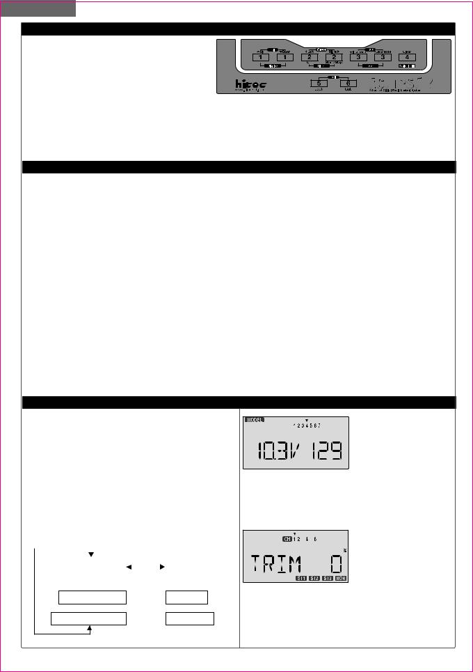
When you first turn on your transmitter, the first screen shown below appears on the LCD display. Before flying, or even starting the engine, BE SURE that the model number appearing in the top center of the display matches the model that you are about to fly!
If you don't, reversed servos and incorrect trims will lead to an immediate crash.
You can scroll up and down through the startup screen by pressing one of the two Edit keys (the two keys on the far left). If you press timer or engine cut or lock keys, you go directly to those functions regardless of the display.
|
Edit keys |
Off key |
|
|
|
Start/Stop key |
|
Voltage/Timer Display |
|
|
|
|
|
|
|
|
|
Timer Display |
||
|
Normal Display Mode |
|
|
|
||
|
|
|
|
|
||
|
|
|
|
|
||
|
|
|
|
|
|
|
Trim Menu [TRIM] 
 Engine Cut
Cut key
Model Name Display 
 Throttle Lock
Lock key
Edit keys
This screen appears at startup. The model
memory number is shown
by the small down-arrow. Battery voltage is shown in
the bottom left,and operating time is on the lower right. You can reset the operating time display by hitting the Clear button (the one on the farthest right). Do this after each charge to keep track of your operating time on a single charge.
Pressing the Up button gives the Trim display (different numbers may
appear depending on the model type). To see where
the trim for a certain channel is, you have to move it! Be sure to move it back to where it was. Note that the CH3 trim only moves downward, so if you need more engine RPM, set up idle with the trim at -25% so you can increase it if needed.
8
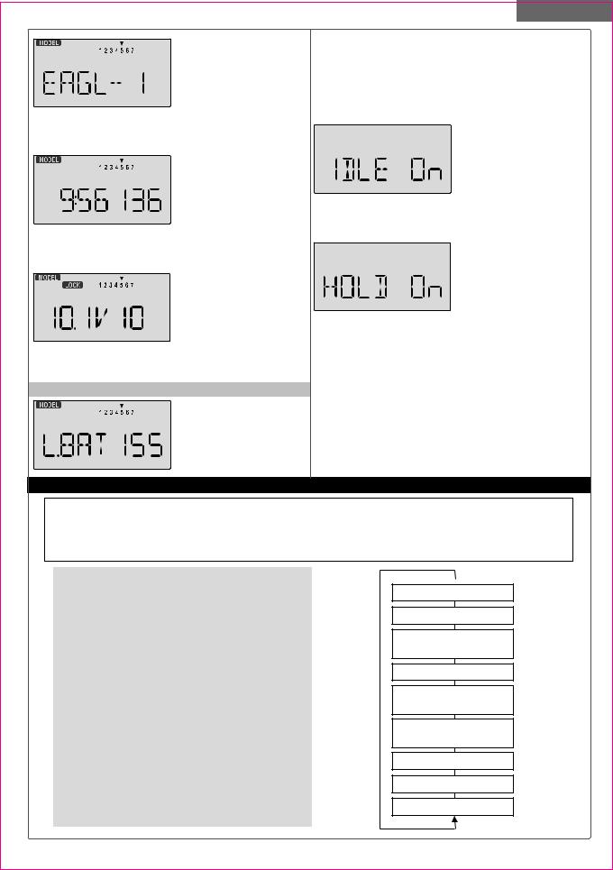
Pressing the Up button again gives the Model Name display. If you've
named your model, it will appear here so you can be
sure you have recalled the correct memory. If you do not name the model, you'll have to remember which model memory it's stored within by the memory number.
Pressing the start/stop button gives the Timer
display, with a stopwatch
display on the left, and operating time on the right.
This also starts the timer, so hit the start/stop key again to stop it. Hitting the Cursor Left (Off) button resets the
timer and returns you to the display mode.
 LOCK indicator Pressing the Lock button
locks the throttle servo
and holds it where you
last commanded it. This may be used as a safety
feature when you are carrying the model and transmitter to ensure you don't accidentally give throttle. It is shown by the LOCK indicator.
Warning Displays
The LOW BATTERY warning is displayed when the transmitter battery voltage drops below 9.3 volts, and a beeper will beep.
Model Setup Functions
The operating time is still shown on the right. If you reset this each time you charge the system, you will have a good idea of how long you can safely operate.
WHEN THE BEEPER SOUNDS, LAND YOUR MODEL AS SOON AS POSSIBLE BEFORE LOSS OF CONTROL DUE TO A DEAD TRANSMITTER BATTERY.
The IDLE ON warning is displayed when the trans-
mitter is powered up with
the Idle-up switch on in the helicopter mode only.
You can turn this off by moving the Flt. Mode switch back. For your safety, the transmitter will not broadcast until this alarm is ended.
The HOLD ON warning is displayed when the transmitter is powered up with
the Throttle hold switch on in the helicopter mode only
when throttle hold values are programed.
You can turn this off by moving the Flt. Cond. switch back. For your safety, the transmitter will not broadcast until this alarm is ended.
Model Setup Functions
This section describes the model setup functions that are used to choose all of the operating features of a particular model memory. These functions are used to select the model memory, the model type (from airplanes, gliders, and helicopters), set the stopwatch, and other useful functions. These functions are used to set up a new model or a new model memory, to switch between memories, and to change transmit shift.
Map of Basic Menu Functions |
(see right) |
||
M.SEL |
Model select |
|
10 |
COPY |
Data Copy |
|
10 |
ACRO |
Acrobatic model mode |
|
10 |
HELI |
Helicopter model mode |
|
10 |
GLID |
Glider model mode |
|
10 |
2WNG |
Two Servo Wing (GLID only) |
|
10 |
4WNG |
Four Servo Wing (GLID only) |
|
10 |
NOR |
Normal swashplate (HELI only) |
10 |
|
120' |
120'Swashplate (HELI only) |
|
10 |
180' |
180'Swashplate (HELI only) |
|
10 |
****Model Name (four letters +
|
up to three numbers) |
11 |
SFT.N |
Transmit Shift |
11 |
TIME |
Timer setup |
12 |
REST |
Reset Memory |
12 |
Power On While Pressing  both Edit/Display keys
Model Select [M. SEL]
Copy Model [COPY]
Model Type [ACRO] [HELI] [GLID]
Model Name [ABCD-199]
Wing Type (GLID only) [4WNG] [2WNG]
Swashplate type (HELI only) [NOR] [120] [180]
Shift Dir. [SFT.N][SFT.P]
Time Setup [TIME XX]
Reset Memory [REST]
9

Model Setup Functions
MODL - Model Select
Your Eclipse 7 system can store up to seven independent sets of model data in its memory. The Model Select (MODL) function allows you to choose from any of the seven sets of model data.
You can assign a four-character name to each model memory. The model names are not visible when you
wish to switch memories. There are several ways to keep This function is used to select the type of model to be
track of which model is in each memory. You may attach |
programmed in the current model memory. You may |
a small piece of white tape to the transmitter and write |
select from aircraft (ACRO), gliders (GLID), and helicop- |
the model's name along with the model setup number |
ters (HELI). If you select glider or helicopter types, you |
(and its channel number), or you may use a notebook, |
will need to set the wing type (for a glider) or the swash |
or label the model with its memory number prominently |
type (for a helicopter). These settings are covered below. |
near its on-off switch outside the fuselage. |
Selecting the Model Type |
Choosing a model memory to load 1. Start with the transmitter switched off.
2. Turn on your transmitter

 Flashing
while pressing both of the two Edit keys (the two keys
on the far left). This gets you into the model select (M.SEL) menu.
3.Select the desired model number by pressing the Cursor Right or Left button. At this time, the small arrow above the selected model number will blink on and off.
4.Switch power off.
5.Switch power back on. The previously-selected model number is indicated by the arrow above the model numbers in the display.
COPY - Copy Model
The COPY function is used to copy the model data stored in the current model memory into another model memory. This function is handy to use to start a new model that's similar to one you have already programmed, and is also handy for copying the current model data into another model memory as a backup.
Copying from one model memory to another
1. With the transmitter switched off, turn on your transmitter while pressing both of the two Edit keys (the two keys on the far left). The model select (M.SEL) menu will be displayed.
2. Press the Up arrow key. |
|
|
Flashing |
|
|
|
|||
This gets you into the mo- |
|
|
|
Destination |
|
|
|
||
del copy (COPY) menu. (If |
|
|
|
(Flashing) |
|
|
|
|
|
you're already in the setup |
|
|
|
|
menus, you can just press |
|
|
|
|
the UP or Down arrow key to get here.) |
|
|
|
|
3.The source model memory (the memory that will be duplicated) is the current one, indicated by the fixed upper arrow. To select your destination model number, press the Left or Right Cursor keys. The selected destination memory number is shown by the flashing triangle under it.
4.Press the +Increase and -Decrease Data keys at the same time. The transmitter beeps twice rapidly, indicating the copy has been completed. THIS WILL ERASE ALL
1.With the transmitter switched off, turn on your transmitter while pressing both of the two Edit keys (the two keys on the far left). The model select (M.SEL) menu will be displayed.
2.Press the Down arrow key. This gets you into the type select menu. The current model type will be flashing on
and off. (If you're already
in the setup menus, you can

 Flashing just press the Up or Down arrow key to get here.)
Flashing |
Flashing |
3.If the model type you want is displayed, you're done. [If you wish to change the wing type or swash type in the GLID and HELI model settings, see the sections below.]
4.If you wish to change the model type from that displayed, press on the Left or Right Cursor buttons until the model type you want, either ACRO,GLID, or HELI, appears.
5.To select your desired model type, press both the
+Increase and -Decrease Data keys simultaneously. Two beeps tell you that the new model type is now registered. THIS WILL ERASE ALL THE OLD SETTINGS IN THE
MODEL MEMORY, SO BE SURE YOU'RE IN THE CORRECT MODEL MEMORY BEFORE YOU CHANGE MODEL TYPE!
6.Press the Up or Down arrow keys to get to another setup menu, or switch power off.
7.Switch power back on. You may now set up the details of your model in the Edit mode.
Wing & Swashplate Type Selection
If you are using the glider (GLID) or helicopter (HELI) setting menus, you must tell the Eclipse system what type of model you are using. In the case of a glider, you have to specify whether it has two (2WNG) or four (4WNG) wing servos (most slope gliders use two wing servos, and competition gliders use four wing servos, two each for outboard and inboard ailerons and flaps). Helicopters may have one servo each for blade angle, roll and pitch(NOR) or they may use three servos in concert on the swash to
10
Model Setup Functions
provide these functions (120', 180'). Note that these menus will not be available unless you have selected the GLID or HELI model types.
Selecting the Wing or Swashplate Type
1. Select the GLID or HELI model type in the Model Type Select menus (see above). 

2. With the transmitter
switched off, turn on your transmitter while pressing both of the two Edit keys
(the two keys on the far left).  The model select (M.SEL)
menu will be displayed. 3. Press the Up or Down arrow keys: In the GLID
mode, you'll enter the wing setup menu, and WING will be highlighted:
If you're in HELI mode, SWASH will be highlighted and you can select from three swashplate types: NOR, 120',
and 180' :
CH2
CH1
NOR
(CH6=PITCH)
CH6 CH1
CH2
120
CH6 CH1
CH2
180
If you're happy with the wing or swash type that is displayed, go on to the next step. If you wish to change the wing or swashplate type from that displayed, press on the Left or Right Cursor buttons until the wing/swash type you want appears. CAUTION: if you change types, you may lose settings in the menus.
4.Press the Up or Down arrow keys to get to another setup menu, or switch power off.
5.Switch power back on. You may now set up the details of your model in the Edit mode.
Inputting a Model Name
1. With the transmitter switched off, turn on your
transmitter while pressing both of the two Edit keys (the two keys on the far
left). The model select (M.SEL) menu will be displayed, with "stars" to represent letters to be chosen.
2.Press the Up or Down arrow key until you get into the model name menu. You'll see the display as shown to the right, with the MODEL and NAME indicators in the upper left on. The first character of the name will be flashing on and off. (If you're already in the setup menus, you can just press the Up or Down arrow key to get here.)
3.To change the first character, press the +Increase and -Decrease Data keys until you see the character you desire. You may select from the upper case letters A ~ Z,  , +, -, /, and the numbers 0 ~ 9.
4.Press the Right Cursor key to move to the next character.
5.Press the +Increase and -Decrease Data keys until you see the character you desire.
6.Repeat the previous two steps to input the third and fourth characters of the display.
7.Press the Right Cursor key to move to the number
displays on the right.
8. Press the +Increase
and -Decrease Data keys until you get to a number that you like. This can be
any number from 0 to 199. If you have lots of models with different frequencies, you may wish to input your channel number here.
9.Press the Up or Down arrow keys to get to another setup menu, or switch power off.
10.Switch power back on. You may now set up the details of your model in the Edit mode.
Transmit Shift - SFT.N, SFT.P
For all 35 and 40MHz versions
The signal shift used with 35 and 40MHz is all the same. The transmit shift menu screen should look like this one, for all 35 and 40MHz Eclipse 7 versions.
Model Name
The Model Name function is used to create an alphanumeric name which is stored in the model memory along with the rest of the model settings. You will find it useful to help keep track of multiple models. The model name can be four alphabetic characters, along with up to three numbers following. The letters may be used to abbreviate the model's name, and the numbers may be used for the memory number, or you may wish to store that model's channel number so you can remember easier.
For 72MHz North American Version.
The Transmit Shift function is used to change the shift direction of the Eclipse 7 system.
With this menu, you can change the way your transmitter broadcasts, so that it can address all types of PPM receivers. (PPM receivers are also referred to as "FM" receivers.) The Eclipse 7 FM is not compatible with PCM receivers, only with FM. Hitec/RCD and Futaba receivers use negative shift (N), and JR and Airtronics receivers use positive shift (P).
If you choose the wrong shift direction for your receiver,
11

Model Setup Functions
the servos will move erratically and will not respond to the transmitter, even if it is on the correct frequency. Turn off your receiver at once to preclude damage to your servos, and change the shift direction.
If you use a mixture of receiver brands, make sure that the transmitter is properly set for the brand of receiver you are using in the current memory.
Changing the Frequency Shift
1. With the transmitter switched off, turn on your transmitter while pressing both of the two Edit keys (the two keys on the far left). The model select (M.SEL) menu will be displayed.
2. Press the Up or Down Edit key until you get into
the shift menu. You'll see
either the word SFT.N or |
|
|
Flashing |
|
|
|
|||
|
|
|
||
SFT.P, with the last charac- |
|
|
|
|
ter, N or P, flashing on and |
|
|
|
|
off. (If you're already in the |
|
|
|
|
setup menus, you can just |
|
|
|
|
|
|
|
Flashing |
|
press the Up or Down |
|
|||
|
|
|
||
arrow key to get here. |
|
|
|
|
3.N represents negative shift and will work with Hitec and brand F. P represents positive shift and will work with brands A and J. The Eclipse 7 will not work with any PCM receivers.
4.To change the shift direction from what is shown, press either the Left or Right Cursor key one time.
This will change the display from P to N or N to P.
5.Press the Up or Down arrow keys to get to another setup menu, or switch power off.
TIME -Timer Function Setup
The timer function is helpful for keeping track of flight duration, engine run time, or other things that need to be monitored during flight. You can set up the timer to count down from 0 to 60 minutes. If you select a time from 1 to
60minutes, the timer will count down the number of minutes selected when you first press the Start/Stop button. You may stop it at any time by pressing the Start/Stop button a second time. Beginning the last 14 seconds of the selected time, the system will beep every second to tell you the time has elapsed. If you wish to reset the timer, just press the Off button, it will then be changed to display mode. You may then press the Start/Stop button to reset it and count down again, whenever you like. If you select 0 minutes, the timer acts like a stopwatch and counts upwards.
Setting up the Eclipse Timer
1.With the transmitter switched off, turn on your transmitter while pressing both of the two Edit keys (the two keys on the far left). The model select (M.SEL) menu will be
displayed.
2. Press the Up or Down arrow key until you get into the Timer (TIME) menu. You'll see a display with the
word "TIME" flashing on and off. (If you're already in the set-up menus, you can just press the Up or Down arrow key to get here.)
3.To change the number of minutes shown, press the
+Increase and -Decrease Data keys until you see the amount you desire. You may select from 0 to 60 minutes.
4.Press the Up or Down arrow keys to get to another setup menu, or switch power off.
5.Switch power back on. You may now set up the details of your model in the Edit mode.
REST - Data Reset
The Reset function is used to clear out an existing set of model data within a single model memory, the current one. This function resets all data to the factory default values, and may be used to get a "fresh start" so that you may begin with a clear memory before you input new model settings into a memory that had been used for another model.
Resetting the memory
1. With the transmitter switched off, turn on your transmitter while pressing both of the two Edit keys(the two keys on the far left).
The model select (M.SEL) menu will be displayed. 2. Press the Up or Down 
 arrow key until you get into
the Reset (REST) menu. This display has the word "REST" flashing on and off.
(If you're already in the setup menus, you can just press the Up or Down arrow key to get here.)
3.IF YOU ARE SURE YOU WANT TO RESET and clear out the current model memory, press both the +Increase and -Decrease Data keys at the same time. The transmitter will beep twice to indicate a successful reset.
4.Press the Up or Down arrow keys to get to another setup menu, or switch power off.
5.Switch power back on. You may now set up the details of your model in the Edit mode.
CAUTION: WHEN YOU COMMAND RESET, YOU'LL ERASE THE MEMORY YOU'RE IN AND LOSE ANY PROGRAMMING YOU HAVE ENTERED. DON'T DO THIS UNLESS YOU ARE POSITIVE YOU WANT TO FLUSH OUT THAT MEMORY AND START FROM SCRATCH WITH THE FACTORY DEFAULT
SETTINGS.
12

AIRCRAFT (ACRO) MENU FUNCTIONS
This section describes the menu functions for fixed-wing aircraft, provides a detailed setup example, and then describes the functions individually. Functions relating specifically to gliders and helicopters may be found in the following sections.
ACRO Functions Map |
(see right) |
||
Simple Aerobatic Airplane Transmitter Setup |
13 |
||
EPA |
End Point Adjust (servo travels) |
|
18 |
D/R |
Dual Rates |
|
18 |
EXP |
Exponential Settings |
|
20 |
FLT.C |
Flight Condition Select |
|
20 |
S.TRM |
Subtrim |
|
21 |
REV |
Servo Reverse |
|
22 |
T.CUT |
Throttle Cut (engine shut off) |
|
22 |
PMX1-5 |
Programmable Mixer #1 - #5 (five total) |
22 |
|
LAND |
Landing function settings |
|
23 |
FLPT |
Flap trim |
|
23 |
E->F |
Elevator Flap mixing |
|
23 |
A->R |
Rudder Coupling |
|
24 |
ELVN |
Elevon mixing (tailless models) |
|
24 |
VTAL |
V-tail mixing |
|
25 |
FLPN |
Flaperon (combined flaps & ailerons) |
|
26 |
Aircraft Trimming Chart |
|
27 |
|
|
|
|
|
Voltage/Timer Display
Normal Display Mode
Press both  Edit/Display key
End Point Adjust [EPA]
Dual Rate Set [D/R]
Exponential [EXP]
Flight Cond. [FLT.C]
Sub-Trims [S.TRM]
Servo Reversing [REV]
Throttle Cut [T.CUT]
Prog. Mix 1-5 [PMX-]
Landing [LAND]
Flap Trim [FLPT]
Elev  Flap Mix [E-F]
Ail  Rud Mix [A-R]
Elevon Mix [ELVN]
V-Tail Mix [VTAL]
Flaperon Mix [FLPN]
Simple Transmitter Setup - Aerobatic Airplane (ACRO)
The following pages will take you step-by-step through the setup process for a sport or aerobatic airplane in the ACRO menu. Going through this complete section will help you learn how to use your system quickly and easily. If you need to set up a helicopter or glider, please refer to the quick setup instructions in the helicopter and glider sections.
|
AIRCRAFT SETUP INSTRUCTIONS (AEROBATIC PLANE) |
|
The aircraft setup procedure presented below uses an |
4. Press the Up arrow until the word ACRO appears, |
|
aerobatic model as an example and assumes that there |
flashing on and off. If it does, you're ready to proceed |
|
are two aileron servos, one in each wing. You can use a |
on to the next step. If not, press the Left or Right |
|
similar procedure to set up your own model; your setting's |
Cursor keys until it appears. You must press both Data |
|
numbers and percentages will probably be different. |
keys to "Save" the setting, after which the radio will beep |
|
If your model only has one aileron servo, skip the instru- |
twice. This is how you select the type of model you wish |
|
ctions referring to flaperon. |
to use, either ACRO, HELI, or GLID. |
|
1. Be sure that all of your servos are plugged into the |
5. WARNING: selecting a different model type will erase |
|
proper receiver channels: |
the settings in the model memory. BE SURE you're in the |
|
CH1 - Right aileron |
CH4 - Rudder CH7 - (optional) |
correct model memory before selecting a new model type, |
CH2 - Elevator |
CH5 - Gear |
or you might accidentally erase a model you're using. (The |
CH3 - Throttle |
CH6 - Left aileron |
other memories will not be affected.) |
2. We recommend that you do this programming exercise |
6. Press the Up arrow once. This gets you into the |
|
with the servos installed in the model and connected to |
model name mode (note the words "MODEL" and |
|
the respective control surfaces. This will enable you to |
"NAME" in the upper left of the display). |
|
immediately see the effect of each programming step. |
7. Now you can select four letters to identify your model. |
|
3. Turn on your transmitter while holding down the two |
With the first of the four letters flashing, press the Data |
|
Edit keys (the two keys on the far left). This gets you into |
+Increase or -Decrease key to change the letter that is |
|
the model select (M.SEL) menu. Press the Cursor Right |
displayed. Stop when the first letter is the one you want. |
|
button to move to a new model memory. The selected |
8. Press the Right Cursor key once to get to the second |
|
model memory you select is indicated by the little flashing |
letter. Repeat the previous step to choose the second |
|
arrow pointing down. |
|
letter. |
Memory #2 is shown here. |
|
|
Aircraft(ACRO) Section
13

Aircraft(ACRO) Section
9. Repeat two more times to fill out the remaining two letters. If you like, you can hit the right cursor button one more time and select a number between 0 and 199 for further identification. It can be handy to use this to store the plane's channel number.
1O. Press the Up arrow once. This gets you into the Timer menu (TIME). If you want, you can use the Data +Increase or -Decrease keys to select the amount of time you want the stopwatch to count down.
11. This completes the initial part of the setup.
Now, we'll go ahead and customize the ACRO settings for your model. Switch transmitter power OFF.
12. Now turn power ON. The transmitter should
display the model number
and battery voltage as shown. The number on the
right is the elapsed time, which will vary depending on how long the transmitter has been left on.
13. Press both Edit keys to get to the regular programming menu. The end-point
adjust menu.(EPA) should appear. Press the Down
arrow to get to the flaperon menu (FLPN).
The display should show that it is inhibited (INH).
14. Turn on the Flaperon
function by pressing the
Active/Inhibit button (Clear) until "On" appears in the display.
15.Be sure that you connect the right aileron servo to receiver CH1 and the left aileron servo to receiver CH6.
16.Later, you can get differential by adjusting the up and down motion of the two servos in the FLPN menu. Now
we'll set the servo throw directions. Now check that
each servo moves the proper direction. We'll use the Reversing function if
they don't. Go to the Reversing menu (REV) by hitting the Down arrow.
17. We'll start by setting the right aileron servo direction. This is channel 1, and the 1 should be flashing for this command. When you move the right-hand stick to the right, the aileron on the right wing should move upwards, and the aileron on the left should move downward. Check that the right aileron moves the correct way!
RIGHT
LEFT RIGHT
LEFT
Front View
18. If it does not, activate the opposite direction for the CH1 aileron servo by pressing the Active/Inhibit (Clear)
key. Each press switches from Reversed to Normal and from Normal to Reverse. In the display, N for Normal is chosen when the little triangle is above the channel number, and R for Reverse is chosen when the little
triangle is below the chann-
el number. Move the right-
hand stick again and verify
the right aileron moves in the right directions.
The display shows Channel 1 reversed.
19. Next we'll set the direction of the elevator servo, channel 2. When you move the right-hand stick towards the BOTTOM of the transmitter, the elevator should move up. Check to make sure it moves in the proper direction! (More planes are crashed due to reversed controls than for any other reason.)
DOWN DOWN 
UP
UP
20.If the elevator control moves in the wrong direction, move over to Channel 2 by pressing the Cursor Right key. Now the '2' should be flashing in the display.
Activate the opposite direction for the elevator servo by pressing the Active/Inhibit (Clear) key. Move the righthand stick up-and-down again and verify the elevator moves the right direction.
21.Now we'll set the direction of the throttle servo. When you move the left-hand stick towards the BOTTOM of the transmitter, the throttle should close, meaning that the hole in the carburetor should close. Check to make sure that the throttle lever on the engine moves in the proper
direction!
HIGH
HIGH Throttle : carburetor fully opened
LOW Throttle : carburetor at idle position
(not fully closed)
LOW
22.If the throttle servo moves in the wrong direction, move over to Channel 3 by pressing the Cursor Right key. Now the 3 should be flashing in the display. Activate the opposite direction for the throttle servo by pressing the Active/Inhibit (Clear) key. Verify the throttle stick makes the servo move the carburetor opening in the correct direction.
23.Now we'll set the direction of the rudder servo. When you move the left-hand stick towards the CENTER of the transmitter (to the right), the trailing edge or rear rudder should move to the right. Check to make sure!
RIGHT
LEFT RIGHT
LEFT
Front View
14

If the rudder moves in the wrong direction, move over to Channel 4 by pressing the Cursor Right key. Now the '4' should be flashing in the display. Activate the opposite direction for the rudder servo by pressing the Active/ Inhibit (Clear) key. Move the left-hand stick left-and right again and verify the rudder moves the right direction.
If your model has retracts, set the correct response direction when commanded by the Gear switch, using the same procedure. If you're using a second aileron servo, you'll now set the left aileron servo direction (otherwise skip this and the next step). This is channel 6, and the '6' should be flashing for this command. When you move the right-hand stick to the right, the aileron on the left wing should move downwards. Check that the left aileron moves the correct way! If it does not, activate the opposite direction for the left aileron servo using the above procedures. Move the right-hand stick again and verify the left aileron moves in the proper directions.
Press the Up or Down arrow keys to the Flap Trim
function (FLPT), and input
a percentage of zero (0) using the Data -Decrease
key. This temporarily disables the flap knob (VR1) so that you can set aileron neutrals without regard to the flap knob position. Later we'll turn it back on.
24.Before we set the servo neutrals, we need to be sure that all the trims are centered. Press both Edit keys to get to the main menu, where voltage and time are displayed. Press the Up arrow until the word TRIM appears.
By moving each of the four trim levers around, you can see their positions, and move them back to zero for the next step.
25.Once you have centered all the trims, unscrew the screws holding the servo arms onto the elevator, aileron, and rudder (we'll set the throttle travel later). You will want to place the servo arms on the output shaft so they are near neutral - that is, about 90 to the servo case sides or, if the servo is mounted sideways, 90 to the pushrod (sideways mounting is not recommended). This way you won't run out of subtrim authority. Remove all the arms that are in the way or interfere with your pushrods.
Servo
Pushrod
90
Adjust the clevises on each servo pushrod to get the position of each control to be as close as you can to neutral (lined up with the adjacent portion of wing or tail).
Setting Subtrims. Now we'll adjust all the subtrims
to electronically set the desired neutral locations. To do so, go back to the
programming menu by pressing both Edit keys, then press the Up or Down arrow key repeatedly until STRM appears.
26.Set the right aileron subtrim first. If the little arrow is not pointing at channel 1, press one of the Cursor
Left or Right buttons until it is (see figure). Then, adjust the subtrim amount by adding or subtracting with the
Data +Increase or -Decrease keys. When you reach a place where the right aileron matches up with the fixed portion of the wing, you are done. If you can't get both to match up, then set the subtrim back to zero and mechanically adjust the clevis to get as close as you can, then readjust the subtrim if necessary.
27.Note 1: you should NOT use subtrims instead of mechanically adjusting the pushrods to be close. This
is because you can reduce the travel of the servo,especially if you have to set the subtrim near 100%. As we stated before, get the pushrods close mechanically first, then use the subtrim adjustment to get it just right.
28.Note 2: if you mess up the number you've entered
or find the percentage the wrong direction, you can get back to zero quickly by pressing the Active/Inhibit (Clear) button. 
29. Repeat the subtrim
adjustment with the elevator servo (CH2). First set the pushrod length mecha-
nically to get as close to neutral as possible, then set the subtrim to get the elevator lined up to be parallel with the stabilizer portion. For full-flying surfaces, use an incidence meter or another method to get the incidence angle recommended by the kit manufacturer or model designer.
30.For the throttle, we recommend not setting a subtrim at this time. You will use the trim tab on the transmitter for setting your idle RPM. To shut off the motor you will use the Engine Cut function. In this way, you don't lose your carefully-set idle position.
31.Most people set up their engines to idle with the throttle trim near center, so that there is room for changes due to humidity and other factors.
32.The Eclipse 7 provides a special throttle trim function which allows the throttle trim lever to work at low throttle levels, but disables it at high throttle.
33.Repeat the subtrim adjustment with the rudder (CH4), gear (CH5), 2nd aileron channel (CH6), and the CH7 function if used. As before, first set them mechanically, then adjust the electronic settings. Be sure you have selected the appropriate channel number each time.
34.Servo EPA (End Point Adjustment). Now we'll go through and set the servo travels for each channel. This is both helpful and important, because you can set
the throw of each servo, in each direction, so that there is no binding. Binding is important because it causes very high current drain, and can lead to a battery dying prematurely. Another use for the EPA function is to adjust the model's total throws to match the recommended
Aircraft(ACRO) Section
15
 Loading...