

Page 1

VERTICAL MACHINING CENTER
VS50/60
INSTRUCTION MANUAL
SPECIFICATIONS
SEIKI-SEICOS Σ16M/18M
Version 1.01
BS-2782-1-0221-E-1-01
1
Page 2

Introduction
Thank you for your having purchased the machine, favoring our product lines for your use.
This manual contains fundamental information on the specification. Please read and fully understand
the contents for your safe machine operation.
In particular , the contents of the items concerning safety in this manual and the descriptions on the
“caution plates” attached to the machine are important. Please follow the instructions contained
and keep them always in mind to ensure safe operation.
The reference record papers on adjusting setting values such as a parameter list are attached to
the machine unit and enclosed in the packing. These are necessary for maintenance and
adjustment of the machine later on. Please keep them safely not to be mislaid.
The design and specifications of this machine may be changed to meet any future improvement.
As the result, there may arise some cases where explanations in this manual could become partly
inconsistent with the actual machine. Please note this point in advance.
In this manual, items on the standard and optional specifications are handled indiscriminately.
Please refer to the “delivery note” for the detailed specification of your machine confirmation.
1
Page 3

CONTENTS
1. INTRODUCTION .................................................................................. 1 - 1
1-1 General Precautions..........................................................................................................1 - 2
1-1-1 Precautions on Machine Operation ........................................................................... 1 - 2
1-1-2 Electric Equipment and NC Unit ................................................................................ 1 - 6
1-1-3 Weights and Measures Table .................................................................................... 1 - 7
2. OUTLINE AND FEATURES OF MACHINE ......................................... 2 - 1
2-1 Construction of Machine.................................................................................................... 2 - 1
2-1-1 Bed ............................................................................................................................ 2 - 1
2-1-2 Column ...................................................................................................................... 2 - 1
2-1-3 Spindle Head..............................................................................................................2 - 1
2-1-4 Table .......................................................................................................................... 2 - 1
2-1-5 Feed Box ................................................................................................................... 2 - 2
2-1-6 Slideway .................................................................................................................... 2 - 2
2-1-7 Automatic Tool Changer (ATC) .................................................................................. 2 - 2
2-1-8 Splash Cover ............................................................................................................. 2 - 2
2-2 Name of Component Units ................................................................................................ 2 - 3
2-3 Specifications of Machine.................................................................................................. 2 - 4
2-3-1 VS50 Machine Specifications..................................................................................... 2 - 4
2-3-2 VS60 Machine Specifications..................................................................................... 2 - 7
2-3-3 Main Accessories .................................................................................................... 2 - 10
2-4 NC Unit Specifications..................................................................................................... 2 - 12
2-5 Main Dimensions Diagram .............................................................................................. 2 - 19
3. SIZE NECESSARY FOR OPERATION................................................ 3 - 1
3-1 Strokes and Machine Reference Point ..............................................................................3 - 1
3-2 Table Dimensions and Working Area Diagram..................................................................3 - 3
3-3 Machining Area and ATC Interference Range ....................................................................3 - 5
3-4 Tool Shank ......................................................................................................................... 3 - 9
3-4-1 Tool Shank (BT-40) and Pull-stud Bolt (12000min-1)................................................. 3 - 9
3-4-2 Tool Shank (BT-50) and Pull-stud Bolt (4500/10000min-1)...................................... 3 - 10
3-4-3 Two-face Clamped Tooling (Spindle Speed: 19,000 min.-1 or More) ....................... 3 - 10
3-5 ATC Tool Limit (BT40)...................................................................................................... 3 - 11
3-6 Spindle Torque/Output Diagram ......................................................................................3 - 14
i
Page 4

1. INTRODUCTION
We are obliged to you for using our machining center.
This manual describes the installation, operation, daily maintenance and inspection, etc. of this
machine in order for you to be able to properly operate the machine and make full use of its
performance. Prior to its installation and test run, read this manual thoroughly to understand the
contents described for handling the machine.
To secure safe operation, follow the safety precautions described in this manual and the
instructions given on the warning signs attached to the machine.
For your general understanding of this machine, the following documents are provided other than
this instruction manual. Refer to them when necessary.
1. Programming Manual
2. Parts List
3. Instruction Manual for OPERATION
4. Instruction Manual for MAINTENANCE
5. Electric Circuit Diagrams
6. Instruction Manual for NC UNIT (PROGRAM, OPERATION, MAINTENANCE)
Such records of adjustment and setting values as “Parameter List” are included in the package of
the machine. Be sure to keep these documents, which is necessary for maintenance and
adjustment of the machine from now on.
Hitachi Seiki pursues a policy of a continuing improvement in design and performance of its
product. The right is therefore reserved to vary specification, and as a result, the contents of these
documents may partly differ from your machine.
1 - 1
Page 5

1-1 General Precautions
These general precautions is quite useful for operators to create good working environment
against accidents and to increase productivity.
1. Be sure to put safety goggles on.
2. Be sure to put safety shoes on.
3. Operate with proper dressing, such as putting a utility cap on, fixing the sleeves and the
cuffs of working clothes.
4. Don’t operate the machine with gloves.
5. Make clean and neat environment by lighting up and keeping dry around the machine. Also
don’t put any obstacles.
6. Remove dust and chips on the machine, high voltage control panel and NC unit. Also
remove them on the floor. Avoid using compressed air as much as possible for these
cleanings.
7. Use a strong enough table to be put around the machine, and take anti-sliding measures
on the surface.
8. Don’t put tools, workpieces, and other items on the machine as well as on the moving parts
of the machine.
9. Don’t give any remodeling to the machine without our permission.
10. About the Machine with Through Coolant
<1> For the spindle core through specifications, be sure to use our specified through pull
stud when discharging the coolant. If you use other pull stud, it could cause a trouble.
<2> For the DIN through specifications, be sure to use our specified DIN through tool
holder when discharging the coolant. If you use other pull stud, it could cause a trouble.
1-1-1 Precautions on Machine Operation
Before trial run, read this manual carefully and understand, the contents well. Witness of our
operation instructors is most recommendable.
MAINTENANCE
1. An operator and maintenance personnel should read the precautions on the caution plate
fitted to the machine and observe them.
Don’t stain, damage or remove the caution plate. If the caution plate becomes hard to read,
contact Hitachi Seiki.
2. Close all the doors and covers except when adjusting work is made.
As for the doors of the NC unit and the power control cabinet, be sure to close them with
special care.
3. Don’t remove or modify the limit switches for the stroke end, for the traveling axes and the
mechanism, or the electric circuit employed for safety.
4. Use regular wrenches and spanners for adjusting or repairing work.
1 - 2
Page 6

LUBRICATION
Since lubrication oil exerts a great influence on machine durability and accuracy, extreme care
must be taken for maintenance of the whole lubricating system. Perform the following check
and maintenance precautions.
1. Fill with the oil specified in the Maintenance manual to the specified amount.
2. Clear the oil port in advance and be careful that foreign substances such as dust, water and
chips do not enter the tank.
3. Check the bottom of the oil jug to see if there is any debris, water or cutting chips, etc.
insides Sufficient care is required to distinguish the oil jug by appropriate color coding and
fixed stock location to avoid mixed use of different kinds of oil.
4. Check the oil periodically and if foreign substances are found, clean the inside of the tank
promptly and replace it with new oil.
Don’t use all of the oil, even from a new can. This is necessary in order to remove water
and sediment etc.
(with option device)
5. Although low levels in the lubrication oil tank are detected by a float switch that flashes an
alarm signal, check to see if discharging is normal. There are two possible problems:
Oil in the tank decreases extraordinarily fast, or it is decreasing too slowly.
6. As for the suction filter fitted to the pump and the in-line filter in the piping circuit, replace
them with new ones once a year as a rule.
7. Air in the main lubrication pipes has been bled when the machine is delivered, but when the
piping is removed for maintenance, bleed air completely at the time of reassembly and
operate the machine after checking the state of discharging at the end.
COOLANT
The soluble cutting fluid is decomposed due to factors such as mixture of lubrication oil and
propagation of micro-organisms that lower cutting and rust prevention efficiency. This causes
various troubles to occur.
When using-soluble cutting fluid, care must be taken of the following points.
1. When selecting soluble cutting fluid, carefully consider lubrication, infiltration, rust
prevention, bubble prevention, reparability against oil and safety needs.
2. Before operation starts and after operation ends, not only remove chips, but also wipe off
soluble cutting oil adhered to each slideway, the rotating parts, the saddle and cross-slide
of the machine and then be sure to apply lubrication oil thinly to those parts.
3. Replace soluble cutting fluid immediately if it becomes vitiated.
1 - 3
Page 7

4. Remove the covers every half year and clean each slideway, X, Y, Z axes ball-screws, each
limit Switch and feed motors etc.
5. As soluble cutting oil is considered for rust prevention, it may be no problem when the
workpiece is wet. However, when dry, it is apt to rust.
Therefore, it is recommendable to apply rust preventive oil before the workpiece dries after
finished machining.
6. Since soluble oil is alkalescent and has a strong degreasing action, the operator is apt to
develop dermatitis.
Therefore, the operator should take appropriate precautions.
7. As for the diluting method and soluble cutting fluid, diluting water they are different
depending on the type of soluble cutting oil, so use it in accordance with the
recommendations of the cutting fluid manufacturer.
8. Since there are instances where extensive micro-organisms are detected in industrial
water, it is recommendable either to check it before use as water for dilution or to use
service water.
9. Do not use a chemical solution type (synthetic type) in water-soluble cutting agents,
because it causes detachment of coating and affects sealing materials and resin materials
adversely.
10.The influences of difference kinds of oil on coolant are as follows: Carefully monitor the
condition the coolant fluid.
Different kinds of oil
Lubrication oil
Rust preventive oil
Mixture
(Emulsification)
Nutritive source of
micro-organism
Seal due to
surfacing
Instabilization
of liquid
Adhesion to
machine
Propagation of
bacilli
Density
abnormality
Propagation of
bacilli
Lowering of density
Lowering of pH
Formation of state
of aversion
Petrifaction,
rust & others
1 - 4
Page 8

OPERATION
1. Be aware of the position of the push button for emergency stop so that the operator may be
able to press it instantly.
2. As for the operation of the machine, proceed in accordance with the procedure described
later.
3. During operation, keep hands away from the rotating sections and movable sections.
4. When disposing of chips that wound round tooling or fell onto the table, it is dangerous to
grasp and pull them. Further, when disposing of chips, be sure to do it after stopping the
machine.
5. When adjusting the position of the coolant nozzle, do it after stopping the machine.
TOOL SETTING
1. When setting up tools, stop a spindle as well as the feed in each axis.
2. Set the tools within the specified lengths and diameters.
3. When setting a tool to the holder, be sure to set outside the machine. If set in the machine,
the spindle may rotate.
OPERATION FINISH
1. After operation of the machine is over, be sure to switch the power OFF in the prescribed
order, clean the machine and apply rust preventive oil to each section of the machine such
as the slide ways.
When soluble cutting fluid is used, perform these jobs with special care.
1 - 5
Page 9

1-1-2 Electric Equipment and NC Unit
When operating the machine or carrying out maintenance checks, pay special attention to the
following points, concerning the electric equipment and NC unit.
1. Do not give shocks to the NC unit, power control cabinet and other machine parts.
2. For the primary wiring of the machine, use the cable size specified in the operation manual.
Do not use an excessively long cabtire cable.
When the primary wiring has to be put on the floor, protect it with a cover against damage
by cutting chips and other sharp objects.
3. While test running the machine, be sure the setting parameter of the NC unit coincides with
the parameter sheet attached to the machine.
4. Do not change the current set values of thermal relays in the power control cabinet, various
control knobs or the parameter data.
5. Do not apply excessive force, e. g. bending force etc., to the connector portion of plugs,
flexible conduits (tubes) or cabtire cables etc.
6. When carrying out maintenance checks on the electric equipment, turn off the
EMERGENCY STOP button on the operation panel, the power of the NC unit, the main
switch of the power control cabinet and the power switch installed in your factory, in this
order.
Start maintenance work after making sure that these switches are turned off. Lock the
power switches in the OFF state as much as possible or put up warning signs. In additions,
place a “DO NOT TOUCH !” tag near the operation buttons of the machine to forbid other
personnel from operating the machine.
7. Handle electric equipment of the machine with particular care and exercise extreme caution
not to allow the machine to get wet.
8. For equipment inside the power control cabinet, use those specified by Hitachi Seiki. Use
always specified fuses. Never use fuses with a higher capacity.
9. Never leave the control cabinet door open, because direct sunshine or camera’s strobe
flash rays may enter the cabinet and damage internal equipment.
10. In case of turning on the power again, execute power on went by equal to or more than two
seconds after power turned off. If the power is turned on during discharge from control
devise by power off, pay attention to the alarm of the machine is displayed some time, due
to normal process is not available.
1 - 6
Page 10

1-1-3 Weights and Measures Table
(Metric and English Conversion)
1. Liner measure
1m (meter) = 39.37 inches = 3.2808 feet = 1.0936 yards
1cm (centimeter) = 0.3937 inch
1mm (millimeter) = 0.03937 inch
2. Square measure
2
1m
(square meter) = 10.764 square feet = 1.196 square yards
2
1cm
(square centimeter) = 0.155 square inch
2
1mm
(square millimeter) = 0.00155 square inch
3. Cubic measure
3
1m
(cubic meter) = 35.315 cubic feet = 1.308 cubic yards
= 264.2 U.S. gallons = 220.0 U.K. gallons
1• (liter, cubic decimeter) = 0.0353 cubic foot = 61.023 cubic inches
= 0.2642 U.S. gallon = 1.0567 U.S. quarts
= 0.2200 U.K. gallon = 0.02745 bushel
3
1cm
(cubic centimeter) = 0.061 cubic inch
4. Weight
1 ton (metric ton) = 0.9842 U.S. (long) ton = 2204.6 pounds
= 1.1023 U.K. (short) ton
1 kg (kilogram) = 2.2046 pounds = 35.274 ounces avoirdupois
5. Others
1 kgf/cm
2
(kilogram force per square centimeter) = 14.223 pounds per square inch
= 0.098 Mpa (Mega Pascal)
1 kg-m (kilogram-meter) = 7.233 foot-pounds
1 - 7
Page 11

2. OUTLINE AND FEATURES OF MACHINE
2-1 Construction of Machine
As shown in Fig. 2-1, the standard configuration of this machine consists of the bed, column,
table, saddle, spindle head, feed boxes and automatic tool changer (ATC).
2-1-1 Bed
The bed has been shaped so as to facilitate disposal of cutting chips. It is provided with
grooves of chip pan on both sides of table traverse. The two grooves are provided with
flow jet coolant as standard specifications. Two oil conveyors also can be provided as
option. Chips and coolant are transported from the machine left side to the right side
outlet, and collected in the chip box on the coolant tank on the right side of the bed.
The bed has two guides to ensure smooth movement of the table.
Bed also has been designed to fit a splash guard on its circumference in order to protect
the surroundings of the machine from being contaminated by cutting fluid and cutting chips.
Proximity of an operator and the table is kept at close range.
2-1-2 Column
Column, taking the shape of a wall type double column, is fixed on the rear and both sides
of the head by bolts, the column supports the saddles with two horizontal guides on the top,
and the saddles supports the spindle head with two vertical guides. The saddles, as they
traverse on the column, excellent in rigidity, stability of accuracy and high velocity.
2-1-3 Spindle Head
Spindle head takes a ram form to assure flexible movement, which shift up and down with
two stripes on guides provided between the saddle and the head. As to the structure inside
the head, the spindle and the tool locking cylinder are arranged in the body. AC built-in
motor features low oscillation and high reliability of the spindle rotation.
2-1-4 Table
The table, which is put on the bed, is smoothly driven by a ball screw set in the center of
the guides.
Nothing is installed around the table except working surface, which enables coolant and
cutting chips to drop without difficulty. Four T-grooves and a straight groove are designed
so that they may be used as a reference for jig fixtures. Since a table base size is wide
enough compared with a table size, an overhang amount is minimized when the table
moves in a traverse direction.
2 - 1
Page 12

2-1-5 Feed Box
Feed boxes are provided at three spots which are on the front part of the bed, at the left
end of the column top and on the top of the saddle. Each driving section has an AC feed
motor, which drives the ball screw directly by the precisely machined coupling. The ball
screw is isolated from cutting chips and coolant, and maintains longtime accuracy free from
maintenance by the self-lubrication system adopted.
2-1-6 Slideway
Each slideway for axial feed uses a precision ball guide having a special structure.
Therefore, it is provided with superior dynamic performance which allows both low noises
and power saving.
Self-lubrication system is adopted to these guides in the same way as the ball screws,
which attains maintenance free guides.
Since an appropriate pre-load is given to the bearing of guideways in a radial direction,
sufficient rigidity is secured even for heady duty cutting.
2-1-7 Automatic Tool Changer (ATC)
The ATC, which is mounted onto the column base, can change tools at the up end position
of the head (reference point).
High rigidity cams are adopted for the twin arms driving, and the spindle tool lock and the
twin arm action are synchronized, which realizes top level high speed ATC.
A tool magazine can store 20 tools as a standard. Due to employment of a fixed tool
address call system, a secure tool change can be done by simple operations
There occurs no interference to workpieces at the time of tool exchange.
2-1-8 Splash Cover
Cover structure which seals the machine until the ceiling is equipped as the standard
specification so that coolant mist produced by high speed operation may not leak outside
the machine.
The front door also opens widely until the ceiling, which facilitate crane entering at the time
of setting up.
2 - 2
Page 13
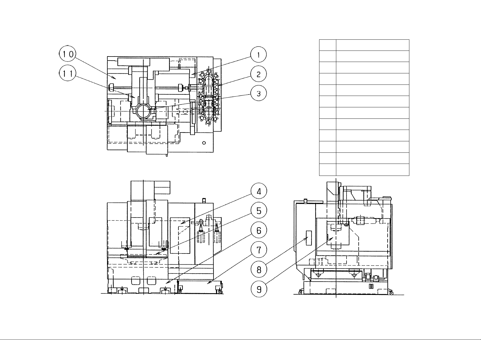
2-2 Name of Component Units
2 - 3
11 Saddle
10 Column
9 Tool changing window
8 ATC operation panel
7 Coolant tank
6 Bed
5 Table
4 Main operation panel
3 Head
2 ATC
1 Main cooling device
No. Name
Fig.2-1 Name of component units
Page 14

2-3 Specifications of Machine
2-3-1 VS50 Machine Specifications
Specifications Unit VS50-50 VS50-40
Stroke
A
*Optional specifications
1) X-axis stroke (Spindle head right & left)
2) Y-axis stroke (Table crosswise)
3) Z-axis stroke (Spindle head up & down)
4) Distance from the table surface to the
spindle nose
5) Distance from the column front to the
spindle center line
Table
1) Table working surface
B
2) Max. table loading capacity
3) Shape of table surface
Spindle
C
1) Spindle speed
Standard spec.
/High power spec.
*High speed spec.
min
min
mm
mm
mm
mm
mm
Mm
kg
-1
{rpm}
-1
{rpm}
1000 (40”)
510 (20”)
450 (17.5”)
150 ~ 600
640
1120 × 510
750
18mm T-slot 4 lines
15~ 4500 35~ 12000
35~ 10000 35~ 20000
2) Spindle speed change
3) Spindle hole taper
4) Spindle bearing
ID
5) Max. spindle
torque
Feed rate
D
1) Rapid traverse
rate
2) Cutting feed rate
3) Jog feed rate
Standard spec.
/High power spec.
*High speed spec.
Standard spec.
*High speed spec.
*High power spec.
(X,Y)
(Z)
mm
mm
Nm {kgfm}
Nm {kgfm}
Nm {kgfm}
mm/min
mm/min
mm/min
mm/min
Stepless
7/24 Taper 7/24 Taper
No.50 No.40
φ100 φ75
φ110 φ65
298 {30.4} 135 {13.8}
233 {23.8} 95.4 {9.7}
166{16.9}
40000
24000
1 ~ 15000
0 ~ 5000 (21 steps)
2 - 4
Page 15

Specifications Unit VS50-50 VS50-40
Automatic tool changer
E
1) Tool shank
*
2) Pull-stud
*
3) Tool storage
capacity
4) Max. tool diameter
( ) : When no adjacent tool exists.
5) Max. tool length
6) Max. tool weight
7) Tool selection
system
Automatic pallet changer
F
1) No. of pallet
*
For 20 tools
*For 30 tools
mm
mm
kg
pcs
MAS 403-BT50 MAS BT40
DIN 50/CAT50 DIN 40/CAT50
MAS P50-0
MAS P50-45
° MAS P40T-1
(45
°)
° MAS P40T-1
(30
°)
20
30
φ110
(
φ180)
300
15 8
Unidirectional random call
Bidirectional random call
2
2) Pallet change system
3) Pallet working surface
4) Max. pallet loading capacity
Motor
G
1) Spindle driving
motor
2) Feed motor
3) Coolant motor
Standard spec.
*High speed spec.
*High power spec.
X, Y
Z
Flood
*Flow jet
*Gun
mm
kg
AC kW
AC kW
AC kW
AC kW
AC W
AC W
AC W
Parallel & swing ARM
1000 × 450
400
11kW (10min)
18.5 (25%ED) 7.5kW (30min)
11 (CONT) 5.5kW (CONT)
25kW (30min) 18.5kW (30min)
22kW (CONT) 15kW (CONT)
22kW (25%ED)
18.5kW (CONT)
3.8
3.8
180 - 2P
400 - 2P × 2
180 - 2P
*Jet
2 - 5
AC W
400 - 2P
Page 16

Specifications Unit VS50-50 VS50-40
4) Spindle cooling
G
system
Power supply
H
(Compressor)
(Pump)
1) Power source
Standard spec.
(Options not
included)
High speed spec.
High power spec.
2) Air source
(MIN)
Tank capacity
I
1) Cutting fluid tank
Standard
capacity
2) Spindle cooling system tank capacity
Machine dimension
J
1) Height of the machine
AC W
AC W
MPa {kgf/cm
• /min
•
•
mm
200-2P
400-2P
200/220V AC
±10% 25kVA
40kVA 31kVA
36kVA
2
}
0.5 {5}
100 (Atmospheric pressure)
420
8.2
2785
18kVA
2) Floor space
3) Machine weight
(Including NC unit)
Standard
Standard
mm
kg
2900 × 2400
8200 8100
2 - 6
Page 17

2-3-2 VS60 Machine Specifications
Specifications Unit VS60-50 VS60-40
Stroke
A
1) X-axis stroke (Spindle head right & left)
mm
*Optional specifications
1270 (50”)
2) Y-axis stroke (Table crosswise)
3) Z-axis stroke (Spindle head up & down)
4) Distance from the table surface to the
spindle nose
5) Distance from the column front to the
spindle center line
Table
1) Table working surface
B
2) Max. table loading capacity
3) Shape of table surface
Spindle
C
1) Spindle speed
Standard spec.
/High power spec.
*High speed spec.
2) Spindle speed change
min
min
mm
mm
mm
mm
Mm
kg
-1
{rpm}
-1
{rpm}
610 (24”)
450 (17.5”)
200 ~ 650
690
1400 × 600
1000
18mm T-slot 4 lines
15 ~ 4500 35~ 12000
35~ 10000 35~ 20000
Stepless
3) Spindle hole taper
4) Spindle bearing
ID
5) Max. spindle
torque
Feed rate
D
1) Rapid traverse
rate
2) Cutting feed rate
3) Jog feed rate
Standard spec.
/High power spec.
*High speed spec.
Standard spec.
*High speed spec.
*High power spec.
(X,Y)
(Z)
mm
mm
Nm {kgfm}
Nm {kgfm}
Nm {kgfm}
mm/min
mm/min
mm/min
mm/min
7/24 Taper 7/24 Taper
No.50 No.40
φ100 φ75
φ110 φ65
298 {30.4} 135 {13.8}
233 {23.8} 95.4 {9.7}
166{16.9}
40000
24000
1 ~ 15000
0 ~ 5000 (21 steps)
2 - 7
Page 18

Specifications Unit VS60-50 VS60-40
Automatic tool changer
E
1) Tool shank
MAS 403-BT50 MAS BT40
2) Pull-stud
3) Tool storage
capacity
4) Max. tool diameter
( ) : When no adjacent tool exists.
5) Max. tool length
6) Max. tool weight
7) Tool selection
system
Automatic pallet changer
F
1) No. of pallet
*
*
*
For 20 tools
*For 30 tools
mm
mm
kg
pcs
DIN 50/CAT50 DIN 40/CAT50
MAS P40T-1
MAS P50-0°
(45°)
MAS P40T-1
MAS P50-45°
(30°)
20
30
φ110
(φ180)
300
15 8
Unidirectional random call
Bidirectional random call
2
2) Pallet change system
3) Pallet working surface
4) Max. pallet loading capacity
Motor
G
1) Spindle driving
motor
2) Feed motor
3) Coolant motor
Standard spec.
*High speed spec.
*High power spec.
X, Y
Z
Flood
*Flow jet
mm
kg
AC kW
AC kW
AC kW
AC kW
AC W
AC W
Parallel & swing ARM
1200 × 560
750
11kW (10min)
18.5 (25%ED)
7.5kW (30min)
11 (CONT)
5.5kW (CONT)
25kW (30min) 18.5kW (30min)
22kW (CONT) 15kW (CONT)
22kW (25%ED)
18.5kW (CONT)
3.8
3.8
180 - 2P
400 - 2P × 2
*Gun
*Jet
2 - 8
AC W
AC W
180 - 2P
400 - 2P
Page 19

Specifications Unit VS60-50 VS60-40
4) Spindle cooling
G
system
Power supply
H
(Compressor)
(Pump)
1) Power source
Standard spec.
(Options not
included)
High speed spec.
High power spec.
2) Air source
(MIN)
Tank capacity
I
1) Cutting fluid tank
Standard
capacity
2) Spindle cooling system tank capacity
Machine dimension
J
1) Height of the machine
AC W
AC W
MPa {kgf/cm
• /min
•
•
mm
200-2P
400-2P
200/220VAC
±10% 25kVA
40kVA 31kVA
36kVA
2
}
0.5 {5}
100 (Atmospheric pressure)
420
8.2
2835
18kVA
2) Floor space
3) Machine weight
(Including NC unit)
Standard
Standard
mm
kg
3155 × 2450
10500 10400
2 - 9
Page 20

2-3-3 Main Accessories
Standard accessories
• Direct tapping 1 set
• ATC, 20 tools
• Chip flow jet coolant ″
• Spindle air flow ″
• Flood coolant ″
• Total enclosed ″
• A TC guard ″
• Operator side door interlock ″
• ATC door interlock ″
• Portable manual pulse generator ″
• Spindle load meter on screen ″
• Spindle speed/feedrate override ″
• Call light (Red or green can select) ″
• Electric leakage detection breaker ″
• W-setter/Easy setter ″
• Safety guard ″
• Spindle cooling unit ″
• Machining completion pre-call/work counter/
″
Run hour display on screen
• Work light ″
• Leveling kit/Spanners and wrenches ″
″
2 - 10
Page 21

Optional accessories (Option)
• High column 200mm
• Closed loop (XY-axis)
• Spindle high speed type
100min
-1
~ 10,000min
-1
• ATC 30 tools
• Pull stud shape changing (MAS P50-45°)
• APC (Parallel shuttle type)
• Outside the machine chip conveyor
• Discharge direction (Back discharge)
• Discharge method (Flat/Scrape/Rolling Filter
/Magnet Roller conveyor)
• Oil skimmer(Belt type)
• Chip wagon w/rollers
• Air blow for cutting point
• Jet coolant
• Power supply on the pallet
• Additional pull stud bolt
• NC rotary table (On the table/on APC)
• Fixture plate (On the table/on APC)
• Sub table for NC rotary table
• Spindle speed meter, (Separate type)
• Spindle load meter, (Separate type)
• Work counter 6-digit
• Run hour meter (Spindle rotation meter/power
on/hydraulic under activating/cycle under
activating)
• Weekly timer
• Additional call light (2/3 Color)
• Call buzzer
• Melody horn
• Mist collector(Water-soluble/oiliness)
• Gun coolant (For table/APC)
• Oil hole coolant
0.5/1.5Mpa (5Ÿ15kgf/cm
2
)
• Sp. through coolant
Kind: Center/DIN
Discharge volume: 0.5/1.5/3.5/7.0Mpa
(5Ÿ15Ÿ35Ÿ70kgf/cm
2
)
• Oil mist (Mist, continuous/Needle, one shot)
• Auto door
• Pallet single unit type 1/type 2
• Metal fastener
• Power supply on table/pallet
• Hydraulic/pneumatic/hydraulic + pneumatic
• M-code out put (M70 ~ M73) (2 pcs./4 pcs.)
• Portable type tape reader
• Handy type FD DON
• Tool length measuring & tool breakage
detection
• Auto. centering (UTS/Renishaw)
• Auto. measuring (UTS/Renishaw)
• On the machine measuring (UTS/Renishaw)
• Measuring master gauge
• Cleaning tool for measuring
• SEIKI-ATAC10 (Y, Z axes thermal change
compensation device.)
• Safety measures for Europe
• Transformer 32kVA
• Tank applicable to Fire Precaution Law
• Operation tools (as specially attached items)
*The contents of accessories and equipment are subject to change without notice. Please
contact the sales department of Hitachi whenever you have any inquiry for answer.
2 - 11
Page 22

2-4 NC Unit Specifications
Refer to Manual (OPERATION) of SEIKI SEICOS Σ16M/18M for details of specifications.
Check list for NC control SECOS
(Export only)
VS50/60 Hitachi Seiki Co., LTD.
standard specifications Σ16M Σ18M
1 Controlled axes
2 Least input increment
3 Interpolation
4 Inch/Metric conversion
5 Tape code
6 Designation
7 Decimal point programming
8 Buffer register
9 Multi-buffer
10 Imposition check per cutting/rapid feed
11 Feedrate command
12 Rapid traverse override
Σ-16M/18M 1998.3.25
3 axes, 3 axes simultaneous
0.001mm/0.0001"
Positioning, Linear, Circular
EIA/ISO automatic recognition
INC./ABS.
12 blocks
F code/feedrate direct
0, 1, 10, 50, 100%
13 Feedrate override
14 Override cancel
15 Spindle override
16 Automatic override memory
17 Direct tapping
18 Manual feed function
19 Manual pulse generator
20 Part program storage
21 Add. registered programs
22 Back ground editing
23 Expanded program edit
24 Display
25 Memory lock
26 Language display
27 Tape mode operation
28 I/O interface
0 ~ 200% (10% step)
50 ~ 150% (10% step)
Rapid, Jog feed, Handle
×1, ×10, ×100 (inch = ×50)
80m
100 pcs.
(Program copy)
10.4" color TFT 9.5" monochrome
English/German
RS232C *
RS232C *
1
1
2 - 12
Page 23

Check list for NC control SECOS
Σ-16M/18M 1998.3.25
(Export only)
standard specifications Σ16M Σ18M
29 Function
30 Spindle speed command
31 Tool position offset
32 Tool length compensation
33 Tool radius compensation C
34 Tool offsets
35 Tool offset memory C
36 Machine coordinate system selection
37 Work coordinate system
38 Pre-set of Work Coordinates
39 Local coordinate system setting
40 Coordinate system setting
41 Reference point return
VS50/60 Hitachi Seiki Co., LTD.
G3, M3, T4
S code/speed direct
G45 ~ G48
G43 G44 G49
G40 ~ G42
32 pcs.
G53
G54 ~ G59
G52
G92
Manual, Auto G27 ~ G29
42 2nd reference point return
43 3rd-4th reference point return
44 Graphic display
45 Program name
46 Single block
47 Block skip
48 Optional stop
49 Dry run
50 Machine lock
51 Z-axis feed cancel
52 Program number search
53 Sequence number search and comparison
stop
54 Program comparison
55 Manual absolute
G30
Before and synchronized machining
16 characters
1 pcs.
[ON] fixed
56 Custom macro
57 Coordinate rotation
58 Fixed cycle
Common variable 100 pcs.
G73 G74 G76 G80 ~ G89
2 - 13
Page 24

Check list for NC control SECOS Σ-16M/18M 1998.3.25
(Export only)
standard specifications Σ16M Σ18M
59 Drilling pattern cycle
60 Right circular interpolation
61 Seiki High Grade-2
(High grade die & mold mach.)
VS50/60 Hitachi Seiki Co., LTD.
G70 ~ G72 G77
(Incl. Spiral)
High precision contouring
control; (With 64 bit RISC
engine)
Advanced control
Linear accel./decel.
Before pre-read
interpolation
Multi-buffer: Pre-read
180 blocks
Feedrate control by
circular acceleration
Automatic feed control
Bell –shaped accel./
decel. Pre-read
interpolation
DNC connection circuit
Graphic guidance
adjustment software
62 Mirror image
63 Chamfering/corner R any angle
64 Radius designation on arc
65 Exact stop
66 Programmable data input
67 Backlash compensation
68 Stored pitch error compensation
69 Run hour display
70 Cycle completion pre-call
71 Cycle time display
72 Work Count
73 Clock function
74 Following up
75 Stored stroke limit 1
76 Stroke check before move
Setting via screen
G09 G61 G64
G10
(On screen)
(On screen)
(On screen)
(On screen)
77 NC self diagnostics
1
*
Interface only
Not include cable.
2 - 14
Page 25

Check list for NC control SECOS
Σ-16M/18M 1998.3.25
(Export only)
Option specifications Σ16M Σ18M
1 F1 digit feed
2 Direct tapping
3 Manual pulse generator
4 High resolving power detection function
(0.1 specification) specification must be
investigated.
5 Polar coordinate command
6 Custom macro
7 Custom macro
8 Custom macro
9 Interruption type custom macro
10 Screen guide special canned cycle
Deep hole drilling
VS50/60 Hitachi Seiki Co., LTD.
Pecking cycle
3 pcs.
Common variable 200 pcs.
Common variable 300 pcs.
Common variable 600 pcs.
G73, G83
Drilling pattern cycle
Square side surface outer cutting
Square lateral cutting
Pocket cutting cycle
Right circular interpolation
11 Seiki high grade-1
(High speed machining)
12 Programmable mirror image
G70 ~ G72 G77
G322 G323
G324 ~ G326
G327 ~ G333
G302 G305
Helical interpolation
Advanced control
Graphic guidance high speed machining
software
High speed boring cycle with helical
interpolation
High speed grooving with Trochoid
machining
2 - 15
Page 26

Check list for NC control SECOS
Σ-16M/18M 1998.3.25
(Export only)
Option specifications Σ16M Σ18M
13 Advanced control (High speed
machin ing)
14 Scaling function
15 Automatic corner override
16 Programmable parameter input
17 Macro print func.
VS50/60 Hitachi Seiki Co., LTD.
•Precedent feed
forward.
•Rapid feed bell type ac
celeration/deceleration
•Linear acceleration/dec
eleration before cuttin
g feed interpolation.
•Automatic corner dece
leration.
•Block overlap function.
•Feed speed clamp by c
ircular radius.
(Need printer w/ RS232C I/F) *
1
18 Program memory length
19 Program memory length
20 Program memory length
21 Program memory length
22 Program memory length
23 Program memory length
24 The number of registered programs
25 The number of registered programs
26 The number of registered programs
27 The number of registered programs
28 Data server
29 Second auxiliary function
30 3-dimensional tool compensation
31 Tool offsets
32 Tool offsets
Total 160m
Total 320m
Total 500m
Total 1000m
Total 2000m
Total 4000m
Total 200 (160m is necessary)
Total 400 (320m is necessary)
Total 800 (1000m is necessary)
Total 1000 (1000m is necessary)
(N/A with DNC connection circuit)
G40 G41
Total 64 pcs.
Total 100 pcs.
33 Tool offsets
Total 200 pcs.
2 - 16
Page 27

Check list for NC control SECOS
Σ-16M/18M 1998.3.25
(Export only)
Option specifications Σ16M Σ18M
34 Tool offsets
35 Tool offset by tool number
36 Work coordinate system
37 Retract to machining interrupted point
38 Retrace
39 48-character program name
40 Block skip
41 Block restart
42 Program restart
43 Manual interruption in handle mode
44 Single direction positioning
45 Helical interpolation
46 Cylindrical interpolation
VS50/60 Hitachi Seiki Co., LTD.
Total 400 pcs.
Total 60 sets
(retract and return)
(Retracing)
Total 9 pcs.
(Incl. add. axis)
47 Hypothetical axis interpolation
48 Involute interpolation
49 Smooth interpolation
50 NURBS interpolation
51 DNC connection circuit RS232C
52 DNC connection circuit RS422
53 DNC2 function
54 External data input
55 Outer I/O device control
56 Skip function
57
Tool life management / Spare tool call
(Used 64 bit RISC)
(Used 64 bit RISC)
(Incl. Remote buffer ,
need technical
discussion)
(N/A with dat a server)
(Incl. Remote buffer, need technical
discussion)
(N/A with data server)
(Only system machine)
(Need technical discussion)
(Need technical discussion)
(High speed)
58 Display of machining time per program
59 Display of machining time per program
60 Cutting monitor
10 pcs. (On the screen)
50 pcs. (On the screen)
(Incl. tool life management / spare tool call)
2 - 17
Page 28

Check list for NC control SECOS
Σ-16M/18M 1998.3.25
(Export only)
Option specifications Σ16M Σ18M
61 Stored stroke limit 2
62 Rotary axis control
63 Add. 1 axis
64 Add. 2 axis
*1Interface only
Not include cable.
VS50/60 Hitachi Seiki Co., LTD.
(Incl. simultaneous control)
(N/A more than 6
axes simultaneous
control)
(N/A more than 4
axes simultaneous
control)
2 - 18
Page 29

2-5 Main Dimensions Diagram
Main dimensions diagram (VS50/60)
Dimension : metric (mm)
inch ( ” )
2 - 19
Page 30

3. SIZE NECESSARY FOR OPERATION
3-1 Strokes and Machine Reference Point
Strokes and machine reference point (VS50)
Dimension : metric (mm)
inch ( ” )
3 - 1
Page 31

Strokes and Machine Reference Point
Strokes and machine reference point (VS60)
Dimension : metric (mm)
inch (
” )
3 - 2
Page 32

3-2 Table Dimensions and Working Area Diagram
Table dimensions and working area diagram (VS50)
Dimension : metric (mm)
inch ( ” )
3 - 3
Page 33

Table Dimensions and Working Area Diagram
Table dimensions and working area diagram (VS60)
Dimension : metric (mm)
inch ( ” )
3 - 4
Page 34

3 - 5
3-3 Machining Area and ATC Interference Range
Dimension : metric (mm)
inch (
” )
Machining area and ATC interference range (Standard specification) (VS50)
Note) There occurs no interference with workpieces at the tool change position under ATC.
But, during approach from working point from change position, depending shapes of
tools and workpieces, interference may be inevitable.
Page 35

Dimension : metric (mm)
inch ( ” )
3 - 6
Page 36

Dimension : metric (mm)
Machining Area and ATC Interference Range
3 - 7
inch (
Machining area and ATC interference range (Standard specification) (VS60)
” )
Note) There occurs no interference with workpieces at the tool change position under ATC.
But, during approach from working point from change position, depending shapes of
tools and workpieces, interference may be inevitable.
Page 37

Dimension : metric (mm)
inch ( ” )
3 - 8
Page 38

3-4 Tool Shank
3-4-1 Tool Shank (BT-40) and Pull-stud Bolt (12000min-1)
1. The concentricity of and parts with the taper shank of a tool shall be 0.025mm
2. The squareness between the taper shank and face
3. The deviation with a 16.1mm wide groove shall be 0.06mm in reference to the groove center.
4. The tolerance of taper shall be +0.000063 (4T of JIS B0612-1965).
0
5. The applicable threads shall comply with JIS B0205-1968, and their accuracy shall meet the 2nd
class requirements of JIS B0209-1968.
6. The squareness between the center line of φ17h7 and face and the rectangular degree of
the face
with the center line shall be 0.01mm, respectively.
3 - 9
shall be 0.015/100.
Page 39

3-4-2 Tool Shank (BT-50) and Pull-stud Bolt (4500/10000min-1)
1. The concentricity of and parts with the taper shank of a tool shall be 0.025mm
2. The squareness between the taper shank and face
shall be 0.015/100.
3. The deviation with a 25.7mm wide groove shall be 0.06mm in reference to the groove center.
4. The tolerance of taper shall be +0.000063 (4T of JIS B0612-1965).
0
5. The applicable threads shall comply with JIS B0205-1968, and their accuracy shall meet the 2nd
class requirements of JIS B0209-1968.
6. The squareness between the center line of
the face
with the center line shall be 0.01mm, respectively.
3-4-3 Two-face Clamped Tooling (Spindle Speed: 19,000 min.
φ25h7 and face and the rectangular degree of
-1
or More)
The BIG-PLUS spindle system(two-face clamping type:made by DAI SHOWA SEIKI) is
normally used for the spindle with speed of 20,000 min
-1
The two-face clamped tools are to be clamped on the end face and tapered section of the tool
shank to prevevt them from biting into the spindle direction by high speed revolution. They are
designed to be well balanced when mounted to the spindle.
The following lists the differences from the regular tools:
[1] Special gauge line IN/OUT amount and 7/24 taper tolerance(equivalent to the JIS B0612 1965, 4T)
[2] Balance grade (JIS B0905) within G2.5
* To purchase the tools, order them to DAI SHOWA SEIKI.
3 - 10
Page 40

3-5 ATC Tool Limit (BT40)
Max. tool diameter D=φ110mm (Tools are stored in the adjacent tool pots)
φ180mm (No tools are stored in the adjacent tool pots)
D=
Max. tool length 300mm
Max. tool weight 8kg
Dimension : metric (mm)
inch (
” )
3 - 11
Page 41

ATC Tool Limit (BT50)
Max. tool diameter D=φ110mm (Tools are stored in the adjacent tool pots)
φ180mm (No tools are stored in the adjacent tool pots)
D=
Max. tool length 300mm
Max. tool weight 15kg
Dimension : metric (mm)
inch (
” )
3 - 12
Page 42

20, 30 ATC Tool Limit
Dimension : metric (mm)
inch (
” )
Note) Can not use a number at each side position of Max. tool that diameter is φ95 and over, in the
case of using the number on the program, the tool will be collided with the ATC arm.
3 - 13
Page 43

3-6 Spindle Torque/Output Diagram
Motor : FANUC αB112L-5.5
Amplifier : SPM-15
The number of maximum rotation : 12000min
(#40 – 12000 Standard spec.)
-1
Spindle speed [min-1]
3 - 14
Page 44

Spindle Torque/Output Diagram (#50 – 4500 Standard spec.)
Motor : FANUC αB160M-11
Amplifier : SPM-30
The number of maximum rotation : 4500min
-1
Spindle speed [min-1]
3 - 15
Page 45

Spindle Torque/Output Diagram (#40 – 12000 High power spec.)
Motor : FANUC αB112L-18.5
Amplifier : SPM-30
The number of maximum rotation : 12000min
-1
Spindle speed [min-1]
3 - 16
Page 46

Spindle Torque/Output Diagram (#50 – 10000 Spec.)
Motor : FANUC αB132L-22
Amplifier : SPM-30
The number of maximum rotation : 10000min
-1
Spindle speed [min-1]
3 - 17
Page 47

Spindle Torque/Output Diagram (#40 – 20000 Spec.)
Motor : FANUC αB112M-15/20000
Amplifier : SPM-30
The number of maximum rotation : 20000min
-1
Spindle speed [min-1]
3 - 18
Page 48

TURNING CENTER
VS50/60
INSTRUCTION MANUAL
SPECIFICATIONS
SEIKI-SEICOS Σ16M/18M
Version 1.01
11-2000
First Edition 2-1998
1
 Loading...