

hitachi seiki VS50, VS 60 Maintenance Manual

MACHINING CENTER
VS50/60
INSTRUCTION MANUAL
MAINTENANCE
SEIKI-SEICOS Σ16M/18M
Version 1.01
BM-2782-1-0221-E-1-01
1

Introduction
Thank you for your having purchased the machine, favoring our product lines for your use.
This manual contains fundamental information on the maintenace. Please read and fully understand
the contents for your safe machine operation.
In particular , the contents of the items concerning safety in this manual and the descriptions on the
“caution plates” attached to the machine are important. Please follow the instructions contained
and keep them always in mind to ensure safe operation.
The reference record papers on adjusting setting values such as a parameter list are attached to
the machine unit and enclosed in the packing. These are necessary for maintenance and
adjustment of the machine later on. Please keep them safely not to be mislaid.
The design and specifications of this machine may be changed to meet any future improvement.
As the result, there may arise some cases where explanations in this manual could become partly
inconsistent with the actual machine. Please note this point in advance.
In this manual, items on the standard and optional specifications are handled indiscriminately.
Please refer to the “delivery note” for the detailed specification of your machine confirmation.
1

CONTENTS
1. INSTALLATION .................................................................................... 1 - 1
1-1 Machine Installation ...........................................................................................................1 - 1
1-1-1 Environment of the Machine ......................................................................................1 - 1
1-2 Foundation and Layout Drawing ........................................................................................1 - 3
1-3 Transport ation of Machine .................................................................................................1 - 5
1-3-1 Precautions for Lifting Work ......................................................................................1 - 5
1-3-2 Precautions When Using the Forklift .........................................................................1 - 5
1-4 Electric Wiring ...................................................................................................................1 - 8
1-5 Air Supply.........................................................................................................................1 - 10
1-6 Oil Supply ........................................................................................................................ 1 - 11
1-7 Mounting Procedure ........................................................................................................1 - 12
2. INSPECTION AND MAINTENANCE ................................................... 2 - 1
2-1 Daily Check and Periodic Check Items .............................................................................2 - 1
2-1-1 Daily Checking Items................................................................................................. 2 - 1
2-1-2 Periodic Check Items ................................................................................................ 2 - 5
2-2 Lubrication, Oil Supply and Coolant.................................................................................2 - 10
2-2-1 List of Lubrication and Oil Supply ............................................................................ 2 - 11
2-2-2 Handling of Coolant Unit .......................................................................................... 2 - 12
2-3 When the Call Light (Yellow Warning Lamp) is Lit Up...................................................... 2 - 17
2-3-1 Kinds of Alarms and Study and Measure of Causes of Obstacles .......................... 2 - 17
2-3-2 Replacing Method of Battery.................................................................................... 2 - 18
2-3-3 Alarm List ................................................................................................................. 2 - 21
2-4 Parameters .....................................................................................................................2 - 32
2-4-1 Kinds and Main Contents of Parameter................................................................... 2 - 32
2-4-2 About a Management of Parameter ......................................................................... 2 - 32
2-4-3 Altering the PC Parameter Setting........................................................................... 2 - 33
2-5 List of SOL/LS Functions and Uses
(See the SOL/LS Layout for the Location of Equipment.) ............................................... 2 - 34
2-6 ATC Maintenance and Adjustment ...................................................................................2 - 37
2-6-1 Drive Mechanism General ....................................................................................... 2 - 37
2-6-2 Explanation of Actions ATC...................................................................................... 2 - 39
2-6-3 ATC (Automatic Tool Changer) Maintenance, Adjustment and Operation................ 2 - 42
2-6-4 Method of Manual Tool Unclamping ......................................................................... 2 - 45
2-6-5 Procedure for Bleeding Air in the Tool Locking System ........................................... 2 - 46
2-6-6 Adjusting a T ool Push Allowance.............................................................................. 2 - 48
2-7 Each Axis Stroke and Zero Point Adjustment................................................................... 2 - 50
2-8 Countermeasures against shift of follow-up coordinate
(shift of memory software OT)........................................................................................ 2 - 54
i

2-9 Adjustment of Synchro Belt Tension for Z-axis Feed ....................................................... 2 - 55
2-10 Instructions for Motor/Inverter for ATC Twin Arm Rotation ............................................. 2 - 56
2-10-1 Setting and Changing the Parameters................................................................... 2 - 56
2-10-2 Initializing the Parameters ..................................................................................... 2 - 57
2-10-3 Monitoring .............................................................................................................. 2 - 59
2-10-4 Errors .................................................................................................................... 2 - 60
2-10-5 Resetting the Inverter............................................................................................. 2 - 63
2-10-6 Inspection and Maintenance .................................................................................. 2 - 64
2-10-7 Troubleshooting ..................................................................................................... 2 - 67
2-1 1 Handling and Maintenance of Spindle Oil Air Lubricating Unit (Option) ..........................2 - 70
2-11-1 Oil Air Lubrication Circuit........................................................................................ 2 - 70
2-11-2 Pump Unit .............................................................................................................. 2 - 71
2-1 1-3 Mixing V alve............................................................................................................ 2 - 73
2-11-4 Daily maintenance ................................................................................................. 2 - 74
2-12 Related to Coolant.........................................................................................................2 - 76
2-13 Related to Air Pressure.................................................................................................. 2 - 80
2-14 Chip Conveyor (For the Inside of St andard Machine) .................................................... 2 - 84
2-15 Spindle Cooling Circuit Diagram.................................................................................... 2 - 85
2-16 Servo Unit......................................................................................................................2 - 86
2-16-1 Alarm Concerning Power Supply Unit
(Source Power of Spindle/Servo Amplifier)............................................................. 2 - 86
2-16-2 Spindle Amplifier Status Display............................................................................. 2 - 89
2-16-3 S pindle Amplifier Alarm .......................................................................................... 2 - 90
2-16-4 Detail of S pindle Amplifier Alarm Contents............................................................. 2 - 95
2-17 List of Supply Items .....................................................................................................2 - 102
ii

1. INSTALLATION
1-1 Machine Installation
When installing NC machine, solid foundation is essential. It is also most important for maintaining
the best condition of cutting accuracy of the machine. The nature of the ground condition of the
factory site, for example, rock base or reclaimed land, makes a big difference. It is, therefore,
difficult to give any definite rules generally applicable to the installation of this machine. (Refer to
the foundation and arrangement drawings.)
The followings are the concrete items to be carefully attended when installing this machine.
2
1) The bearing capacity of soil should be 5 ton/m
be 300mm or thicker.
2) The area of the foundation should be extend to at least 300mm outer circumference of the
machine bed.
3) When digging vibration proof drains, they should be dug along the circumference of the
foundation.
4) Placing separate concrete blocks underneath each machine leg instead of a real foundation is
often seen, which is just not adequate. Such is no value as proper foundation,
or larger and thickness of the foundation should
As this machine yields large volumes of chip during machining, carts are often used for chip
disposal. The traffic of carts and detaching covers in maintenance work need free space so that
the operators can move around without touching other machines. This factor should be
considered when selecting the installing position of the machine.
1-1-1 Environment of the Machine
Pay full attention to a room temperature, dust, vibrations, etc. in order to make use of the
primary performance of the machine. High accuracy cannot be obtained in the environment
where the room temperature greatly changes. Just a slight change of the room temperature
partly affects the machine. Be fully careful of effects heat transfer from the direct sunshine,
vent, heating unit, and so on.
Under the environment where the air is polluted so much by dust, etc., the sliding sections and
electric devices of the machine are greatly effected in their service lives.
Particularly, electronic devices related to controls are susceptible to dust and humidity. Install
the machine in the environment as clean as possible.
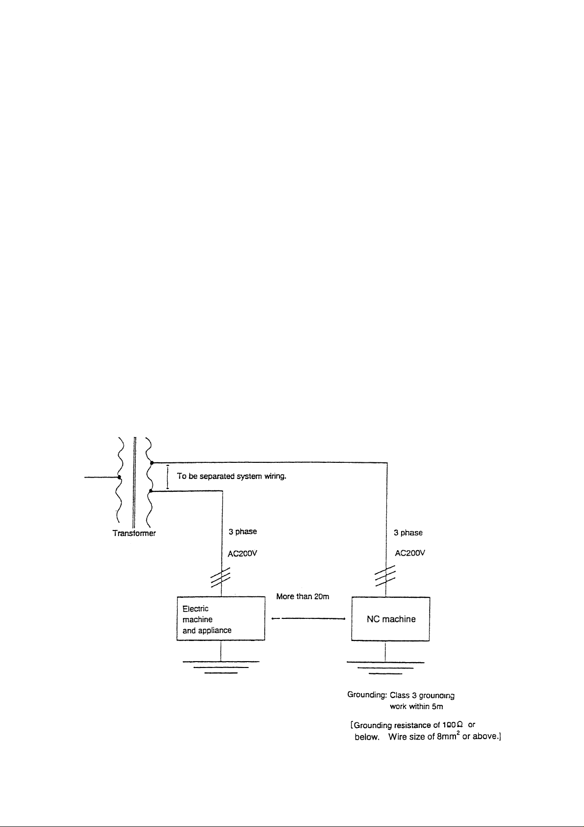
1. Installation Environment of NC Machine
In case that electric machines and appliances generating high frequency noise are
installed or newly erected near by NC machines, keep to the following precautions.
1) Example of the electric machines and appliances generating high frequency noise.
[1] Arc welding machine
[2] Resistance welding machine
1 - 1
[3] High frequency drying machine
[4] Electric discharge machine
[5] Others
2) Installation form of NC machine
[1] Power supply line
The power supply line (AC200V) of NC machine must be separated line with that for
electric machines and appliances.
If impossible, connect the line at the point more than 20m apart from the point where
the power supply for electric machines and appliances is connected.
[2] Installation place of NC machine
NC machine must be installed more than 20m apart from electric machines and
appliances.
[3] Earth of NC machine
The earth of NC machine must be grounded within 5m from NC machine separating
from the ground of electric machines and appliances, and make a ground work with
not more than 100
Or the earth wire size must be not less than 8mm
Ω or comply with the laws and regulations of the country.
2
.
3) Example of earth of NC machine
The earth state of NC machine and electric machines and appliances illustrated as
under.
Power receiving equipment
1 - 2
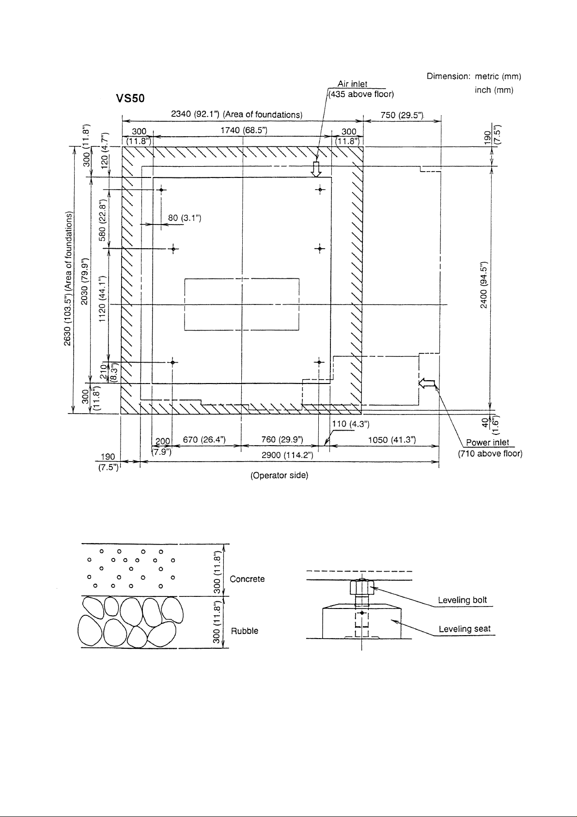
1-2 Foundation and Layout Drawing
Note) 1. Ground bearing force should be 5ton/m2 (1000 lbs/ft2) or more. And foundation
thickness should be at least 300mm. (12”)
2. The area of foundations is to be 300mm (12”) or more of the circumference of the
machine bed.
3. Install the tremor insulating groove along the outer periphery of the foundation.
1 - 3

Foundation and Layout Drawing
VS60
Note) 1. Ground bearing force should be 5ton/m2 (1000 lbs/ft2) or more. And foundation
thickness should be at least 300mm. (12”)
2. The area of foundations is to be 300mm (12”) or more of the circumference of the
machine bed.
3. Install the tremor insulating groove along the outer periphery of the foundation.
1 - 4

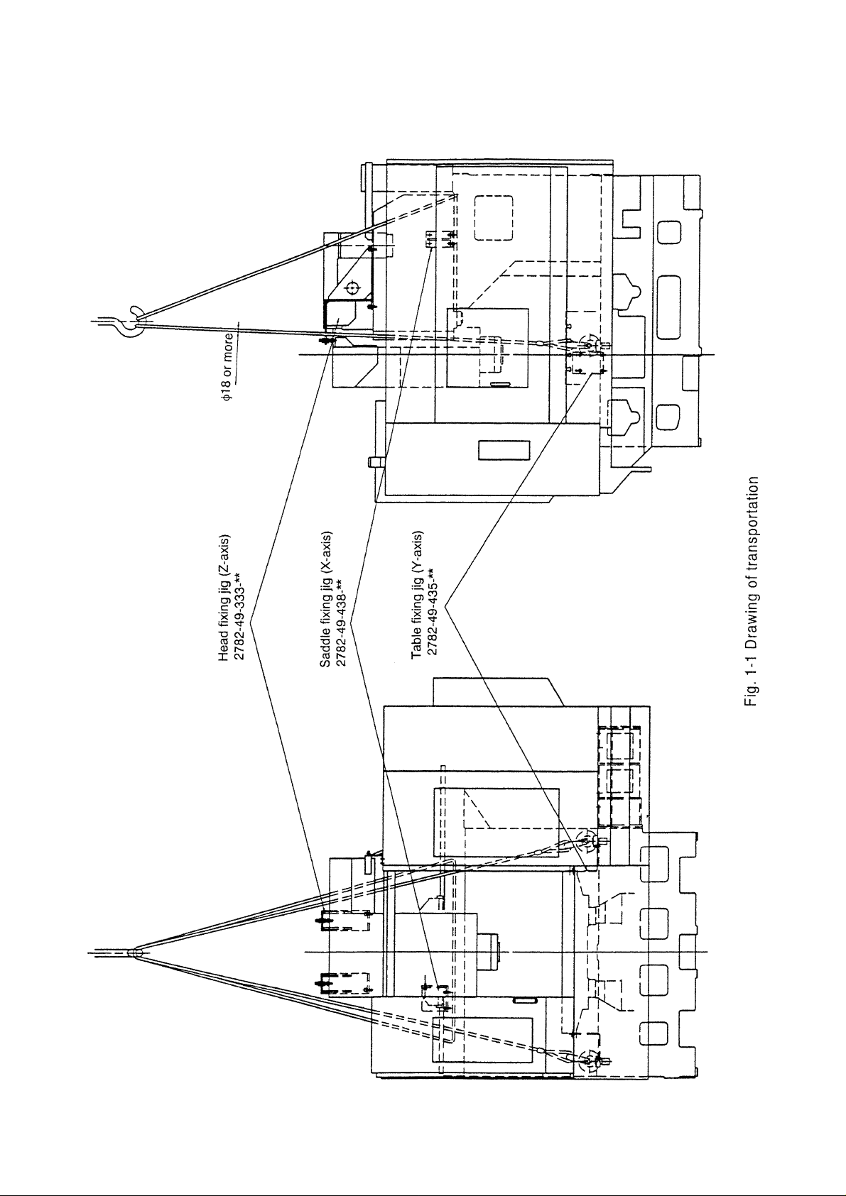
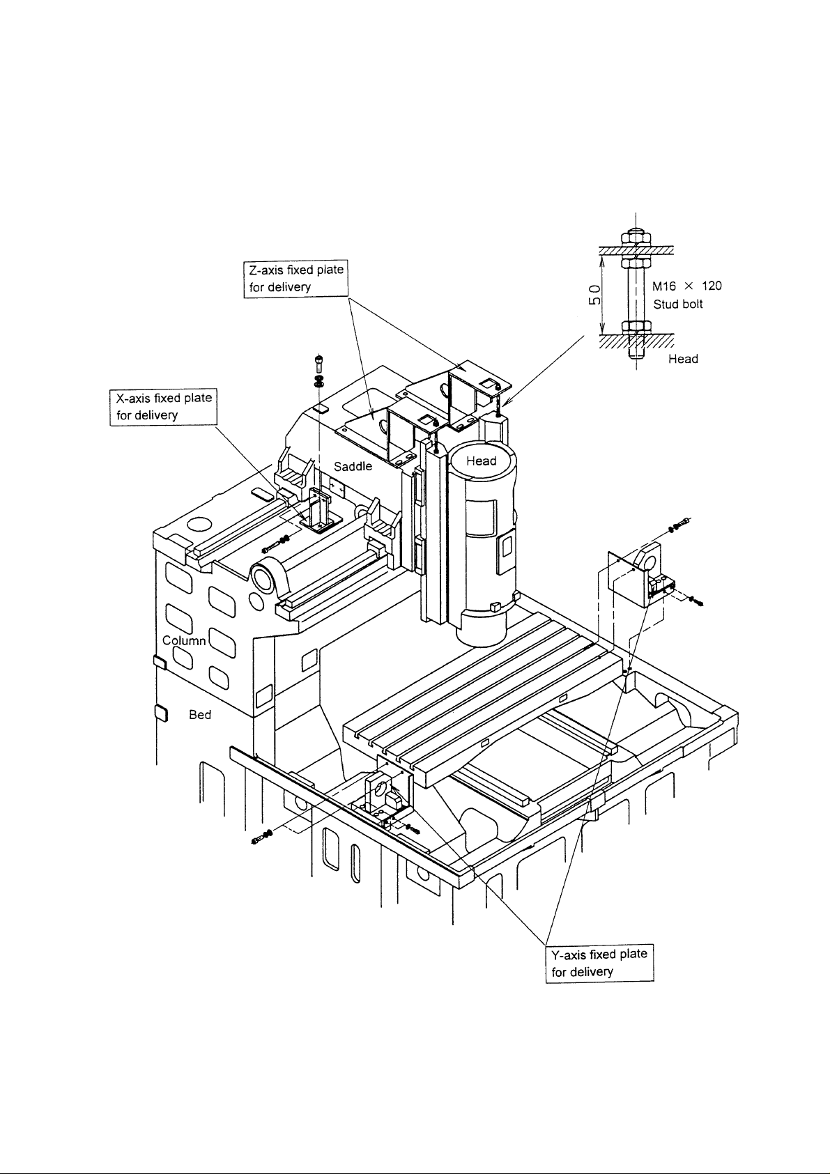
1-3 Transportation of Machine
Since this machine has an integrated structure mechanically and electrically, it can be
transported only by detaching its power cord. To fix its moving parts and pass wire ropes
around the machine, refer to Fig.1-1.
1-3-1 Precautions for Lifting Work
Pay proper attention to lifting work, because it is one of important steps when transporting
the machine.
! WARNING
Since the lifting work for machine transportation is carried out with a crane or chain
block, its precautions are listed below:
(1) Use a wire rope whose diameter is 14 mm (0.55 inch) or more.
(2) Apply a pad to an acute-angle part to protect the wire rope and machine.
(3) Pass the rope so that the center of gravity of a load will come over the center line of a
lifting angle.
(4) Do not use a rusted wire rope, one which has been untwisted, or one whose core wire
is broken.
(5) Lift the machine gradually. Stop it once when the wire rope become strained, and
check a lifting conditions. When the machine is lifted up from the floor, check again
that there are no abnormalities with the lifting rope, and proceed with the lifting rope.
When lowering the machine, it is necessary to be careful that it is lowered down slowly.
Stop lowering the machine immediately before it reaches the floor to check.
Then, lower it down completely.
1-3-2 Precautions When Using the Forklift
! WARNING
Since the lifting work for machine transportation is carried out with a forklift, its
precautions are listed below:
1 - 5

(1) Select a fork lift which has a sufficient capability to handle and endure a machine
weight.
(2) In order not to damage the outer projected parts of the machine, it is necessary to
carry out this work in cooperation with a watchman.
(3) When inserting the fork under the machine, use the right and left cast grooves
provided for fork insertion under the base of the machine proper.
(4) When lifting the machine, be sure to carry out temporary lifting so that you can lift it
with the center of gravity of the machine set at the stablest positions in both
longitudinal and crosswise directions.
1 - 6
1 - 7

1-4 Electric Wiring
Wires between the machine proper and accessories will be connected by Hitachi Seiki. Wiring
from the power supply source to the electric cabinet should be prepared in advance by the
customer.
For this purpose, use wires of thickness specified in the following table, depending on the
distance from the power supply to the electric cabinet.
Power supply : 200/220V (50/60 Hz)
±10%
Source Power Capacity
The electric capacity required for the machine varies depending on the specification of the
spindle and the type of option attachments. To calculate the capacity of the machine being
installed, add the capacity of option specification on to that of the standard machine.
Machine Electric Capacity = Standard Machine Electric Capacity
+ Total Electric Capacity of Option Attachments
Power Capacity of Standard Machine
Spindle Specification Power Capacity
4500 min
10000 min
-1
-1
25 kVA
40 kVA
12000 min-1 Standard 18 kVA
12000 min-1 High output 36 kVA
20000 min
-1
31 kVA
Option Attachment requiring Additional Power Capacity
Option Attachment Additional Power Capacity
Oilhole Coolant 0.5MP A 1.3 kV A
Oilhole Coolant 1.5MP A 1.4 kV A
Oilhole Coolant 7.0MP A 3.7 kV A
Through Coolant 0.5MPA 1.3 kVA
Through Coolant 1.5MPA 1.4 kVA
Through Coolant 7.0MPA 3.7 kVA
Jet Coolant 1.0 kVA
Gun Coolant 0.4 kVA
Mist Collector 1.1 kVA
Hydraulic Power Source 1.3 kVA
1 - 8

Thickness of Wire
The source power wire thickness varies depending on the specification ofthe spindle. Use the
wire of the following thickness to meet the specification.
Spindle Specification Source Power Wire Minimum Grounding Wire Minimum
Thickness Thickness
4500 min
10000 min
-1
-1
38 mm
60 mm
12000 min-1 Standard 22 mm
12000 min-1 High output 50 mm
20000 min
* The thicknesses of the source power wire in the above table are calculated on the assumption
-1
50 mm
that three 600V vinyl coated wires are set in a conduit pipe at the ambient temperature is
30°C.
2
2
2
2
2
8 mm
8 mm
8 mm
8 mm
8 mm
2
2
2
2
2
1 - 9

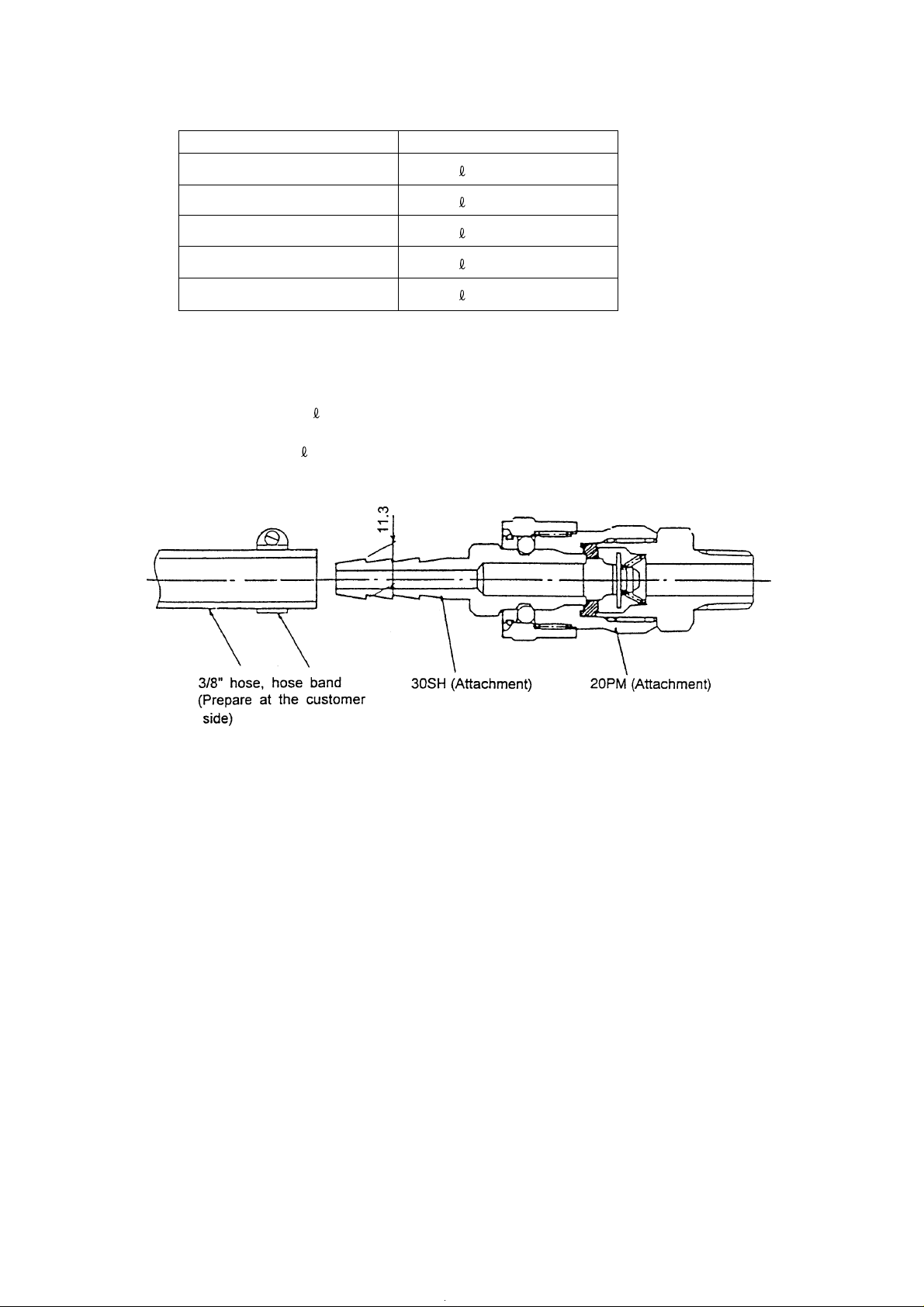
1-5 Air Supply
This machine uses clean air to clean the spindle hole and the tool, for Z axis sliding face and
automatic door, or for oil mist unit. The air supply should be prepared by the customer.
Its joint of the machine is of PT1/4, female.
Air pressure : 0.5MPa {5 kgf/cm2} (72 PSI) or more
Flow : 100
*It is recommended to install an air tank having a capacity of 40• or larger, as there are cases
when supply of a large volume of air is needed instantaneously.
The machine proper is provided with an air filter and regulator to remove dust and
supersaturated moisture from air. When the temperature of the air from the air supply is
higher than that of the machine proper, air gets cooled at the machine proper and tends to
form water drops.
Jetting air containing water is prone to cause rust on the spindle hole and tool shank, which
may affect machining accuracy and cutting surfaces. Therefore, the temperature of the air
from the air supply should below. (Water and dust accumulating in the air filter is automatically
drained. To manually drain them, see the descriptions on mechanical drain operation.) In
case there is a large difference in temperature, install an air drier between the air supply and
the machine.
Flow rete
•/min. (ANR) (Standard Specification)
The flow rate to be set varies depending on the option specification. Therefore, the flow rate
applicable to the actual machine should be determined by the flow rate for the standard
specification machine added by the total required flow rate for the option specification.
Flow rate for the machine = Standard flow rate + flow rate for option specification
Standard specification
Machine specification
#40-12000min
-1
Flow rate
/min (ANR)
100
1 - 10
Additional flow rate required by optional specifications
Optional specification
Tool nose air blow
Center-through air blow
Pulscale X, Y
Oil mist/Needle 1 shot
Semi-dry processing unit
In case with APC (essential)
Air pressure: 0.5MPa (5kg/cm
Flow rate: 100 /min (ANR)
Air tank capacity: 40
or larger
Flow rate
300 /min (ANR)
300 /min (ANR)
60 /min (ANR)
60 /min (ANR)
300 /min (ANR)
2
) or higher
1-6 Oil Supply
When adding lubricating oil, take care of the following:
1. Add the specified amount of the designated oil. Do not use different oils, and do not add to
much of oil.
2. Clean the oil supply port in advance. See that dust, etc. do not enter.
3. When adding oil, set a filter on the oil supply port, so that dust and other foreign substance
will not enter. In case a filter is not available, use a wire netting of 150 mesh or more.
4. Always use new oil. Do not use a mixture of new and old oil.
5. Even when using new oil, do not use all the oil from the can. Always leave some oil in the
can. This is necessary to avoid sediments in the can being used.
For the oil supply positions, intervals, oil amount and quality, see “5-2 Lubrication and Oil
1 - 11

Supply”.
1-7 Mounting Procedure
(1) Dismounting fixtures for shipment and transportation
Upon installing the machine at a fixed place, be sure to dismount the fixtures for
shipment/transportations .
• Remove the fixed plate for the table, column and head.
(2) Installation
A leveling method is one of the factors which determine machine accuracy. Proper
leveling of the machine is most fundamental.
Carry it out carefully, because it affects not only machining accuracy, but also machine’s
service life.
First, put leveling pads at installation points on the floor.
Install the machine so that the leveling adjust bolts attached to the machine legs will be
placed on them.
Use precision levels whose sensitivity per graduation is’ about 0.02 mm/m (0.00025 in./
ft.) and length is about 200 mm (8 in.).
Levels used for woodworking/engineering are not recommendable.
Place the levels with the same end in the same direction.
Keep level-placing surfaces clean at any time lest dust, etc. should be caught under the
levels.
Outline of Installation Work
[1]Confirming a foam in a level
Adjust so that a foam does not get too long and set it at the center on the table. By
turning it by 180
same direction, level has been obtained.
[2]Adjusting the absolute level
As shown in Fig.5-5, place levels on the table in parallel with the X and Y directions,
and measure the level of the machine at 3 places in the X and Y directions,
respectively.
°, while holding the position, and observing a foam in memory of the
1 - 12

Adjust the level of the machine with the leveling bolts so that each difference in
reading of the levels may be settled within 0.04 mm/m (0.0005 in./ft.) in both X and Y
directions.
[3]Adjusting the table operating level
Place the levels at the center of the table and move the X axis almost over its full
stroke. Make adjustment in such a way that each difference in reading of the levels
at this time will meet within the following target values:
• For the level put in the X-axis direction: 0.02 mm/m (0.00025 in./ft.)
• For the level put in the Y-axis direction: 0.04 mm/m (0.0005 in./ft.)
[4]Reconfirm the above-mentioned steps [1] through [3] and make fine adjustment, if
necessary.
[5]When the stable operating levels in [3] cannot be obtained, it is likely that the
condition of the floor, where the machine is installed, is improper. Check and improve
it, referring to the foundation drawing.
1 - 13

VS50
Fig.1-2
Fig.1-3
1 - 14
VS60
1 - 15

2. INSPECTION AND MAINTENANCE
2-1 Daily Check and Periodic Check Items
2-1-1 Daily Checking Items
The following are maintenance items to be checked by operators. These maintenance
items are important to prevent machine trouble and to perform efficient operation.
Perform maintenance according to the following daily check list.
2 - 1

Daily check list
Checking part Check item Details of checks
1. Main cooling unit a)Check main cooling unit for ⇒Check for sound of fan running
operation.
b)Check cooling unit for sufficient ⇒Oil level check
quantity of oil. (Checks before
starting work)
c)Check that air filter is thoroughly ⇒Checks for clogging and
cleaned. cleaning
d)Check for oil leakage. ⇒Check for oil leakage
2. Pneumatic unit a)Check for normal set pressure. ⇒Normal value: 5 kgf/cm
b)Check pneumatic unit for faults ⇒Check for air leakage
such as air leakage.
3. Coolant unit a)Check coolant unit and piping for ⇒Checks for coolant leakage and
faults. abnormal noise
b)Check coolant unit for sufficient ⇒Oil level check
quantity of coolant.
c)Check that air filter is thoroughly ⇒Checks for clogging and
cleaned. cleaning
d)Check for discharge. ⇒ Visual check
e)Check for oil leakage. ⇒Check for oil leakage
4. Operation panel a)Check that alarm is not displayed ⇒Visually check it to determine
and control panel on the screen. (Battery alarm, the cause for corrective action.
etc.)
b)Check that cooling fan is running. ⇒Visually check it to determine
the cause for corrective action.
5. Spindle head a)Check that running-in performed. ⇒Run in the spindle according to
“Spindle warm-up” section of
the operation manual.
b)Check for abnormal noise. ⇒Check for abnormal noise
(M/C, NCL) during spindle running
c)Check spindle gear lubricating ⇒Check that spindle head
float. (TG) (Checks before ascends when spindle runs and t
starting work) hat it descends when spindle
comes to a stop.
d)Check that spindle tapered ⇒Check for removal of dust,
portion is cleaned. (M/C) fouling and foreign matter such
as chips
e)Check spindle for start, stop and ⇒Check that spindle start and
faults. (NCL, spindle) stop do not spend time too
much.
6. ATC magazine a)Check that tool pots and tapered ⇒Check for removal of dust,
portion are cleaned. fouling and foreign matter such
as chips
b)Check that ATC grip portion is ⇒Check for removal of dust,
cleaned. fouling and foreign matter such
as chips
c)Check pull stud for tool for ⇒Check pull stud for tightness
looseness. when changing tools.
2
2 - 2

Checking part Check item Details of checks
7. Table unit a)Check that telescopic cover is ⇒ Check for removal of foreign
cleaned. matter including chips and chips
on wiper portion
b)Check the quantity of table ⇒ Oil level check
indexing gear lubricating oil.
8. Feed unit a)Check for abnormal noise. ⇒ Check for abnormal noise when
operating feed unit
9. Covers a)Check that covers are not ⇒ Check that covers are not
detached. detached. If any cover is
detached, attach it.
b)Check that window is cleaned. ⇒ Check for cleaning
c)Check that nameplate and ⇒ Check for cleaning
caution plate are cleaned.
10. Interlocking a)Check door interlocking function. ⇒ Check that spindle does not run
device when opening door.
1 1. Hydraulic unit
(Option) kgf/cm
a)Check for normal set pressure. ⇒ Normal value: 35 kgf/cm2, 45
depends on the model.)
2
and 70 kgf/cm2 (It
b)Check hydraulic unit for faults. ⇒ Checks for abnormal noise and
oil leakage.
c)Check hydraulic unit for sufficient ⇒ Oil level check
quantity of oil.
d)Check that oil temperature is ⇒ Oil temperature check: Proper
60°C or less. temperature is 60°C or less.
e)Check for oil leakage. ⇒ Check for oil leakage
12. Lubricating unit a)Check for proper consumption. ⇒ 1 liter/10 hours as a guide
(When equipped b) Check lubricating unit for ⇒ Oil level check
with a high- sufficient quantity of oil.
speed spindle.) c)Check that air filter is cleaned. ⇒ Checks for clogging and
cleaning.
d)Check for oil leakage. ⇒ Check for oil leakage (Shorten
checking intervals depending on
working environment.)
13. High-pressure
a)Check high-pressure unit and ⇒ Checks for coolant leakage,
coolant piping for faults. abnormal noise and abnormal
(Option) vibration.
b)Check for discharge. ⇒ Visual check
c)Check pump for discharge ⇒ Normal value: 35 kgf/cm
2
pressure. (Pressure gage) kgf/cm
(It depends on the
2
or 70
specifications.)
d)Check that air filter is thoroughly ⇒ Checks for clogging and
cleaned. cleaning
e)Check high-pressure pump for ⇒ Oil level (cap oil filling) check
sufficient quantity of oil. and replenishment
f) Check for high-pressure pump oil ⇒ Checks for oil degradation and
fouling. oil color
g)Check for sufficient quantity of ⇒ Check through main tank
coolant.
2 - 3

Checking part Check item Details of checks
14. APC
(Option) is cleaned. matter including chips
a)Check that pallet seating surface ⇒ Check for removal of foreign
b)Check that pallets and cover ⇒ Check for removal of foreign
portion are cleaned. matter including chips
15. Chip conveyor
(Option) conveyor. obstructions such as workpiece,
a)Check for obstructions on the ⇒ Check for removal of
tool and square bar
b)Check the quantity of chips in the ⇒ Check the quantity of chips and
chip box and that of coolant. that of coolant, and dispose of
them as necessary.
c)Check that a large quantity of ⇒ Prevent a large quantity of chips
chips collect on the chip from collecting on the conveyor.
conveyor. (Inclusive of screw Check that conveyor operates
conveyor) to discharge chips.
d)Check for abnormal noise. ⇒ Check for abnormal noise when
operating chip conveyor
16. Mist collector
(Option) in the hose. hose route.
a)Check that mist does not remain ⇒ Visual check Provide angular
b)Check that filter is thoroughly ⇒ Checks for clogging and
cleaned. cleaning
c)Check that oil is properly drained. ⇒ Visual check for proper oil
drainage
d)Check mist for leakage. ⇒ Visual check
2 - 4

2-1-2 Periodic Check Items
Periodic checks by maintenance personnel are essential for assuring continued machine
accuracy. Perform maintenance at regular intervals according to the following periodic
check list.
2 - 5

Periodic check list
Checking part Check item
1.
Main cooling
unit
2.
Pneumatic unit
Coolant unit
3.
Operation
4.
panel and
control panel
Table unit
5.
Feed unit
6.
a) Check piping for
faults.
b) Change hydraulic
fluid.
a) Check piping for
faults.
b) Check that filter is
thoroughly cleaned.
a) Check for
conspicuously dirty
coolant unit.
b) Check for foul smell.
c) Check piping for
faults.
a) Check for
conspicuously dirty
operation panel and
control panel.
(Cleaning)
b) Check for foreign
matter in the control
panel.
c) Check that air filter is
thoroughly cleaned.
d) Check that cooling fan
is cleaned.
e) Check power supply
and voltage.
a) Check bolts on the
telescopic cover for
looseness.
a) Check ball screw and
guide for lubrication
(oil and grease).
Checking interval
13612
O
O
O
O
O
O
O
O
O
O
O
O
O
O
⇒Check for oil leakage,
⇒Clean the inside of tank
⇒Check for oil leakage,
⇒Checks for clogging and
⇒Refer to Coolant section
⇒Check for oil leakage,
⇒Visual check and
⇒Removal of foreign
⇒Checks for clogging and
⇒Check for dirty cooling
⇒Check that secondary
⇒Check bolts for
⇒Visually check oil film.
Details of checks
and tighten connector
securely if necessary.
and strainer, and
change hydraulic fluid
as necessary.
and tighten connector
securely if necessary.
cleaning (Shorten
checking intervals
depending on working
environment.)
in the instruction
manual. (NCL)
and tighten connector
securely if necessary.
cleaning
matter
cleaning (Shorten
checking intervals
depending on working
environment.)
fan
voltage of main breaker
is set within + - 10% of
the specified value.
tightness, and tighten
them if necessary.
2 - 6

Checking part Check item
7.
Belt, Timing
belt (Z axes,)
8.
Level
9.
LS and SOL
10.
Cover
11.
Wiper and
brush
12.
Interlocking
device
13.
Cable
14.
OT (Overtravel)
15.
Earth leakage
breaker
a) Check belt for
deflection.
b) Check surface for
damage and heights
for deterioration.
a) Check the level of bed
and table with level
vial.
a) Check that LS and
SOL are not
moistened with oil.
b) Check for oil fouling.
a) Check mounting bolts
for looseness.
a) Check wiper and
brush for deterioration
and damage.
b) Check for jamming of
chips and foreign
matter.
a) Check spindle speed
limiting interlocking
function.
a) Check for damaged
appearance (tears,
crushes, stripped
conductor, etc.).
b) Check connector for
looseness.
c) Check for caught
cable.
d) Check that cable is not
moistened.
a) Check LS for
actuation.
a) Check breaker for
operation.
Checking interval
13612
O
O
O
O
O
O
O
O
O
O
O
O
O
O
O
⇒ Check deflection
⇒ Visual checks and
⇒ Level check and
⇒ Determine the cause to
⇒ Cleaning
⇒ Check cover clamping
⇒ Visual checks
⇒ Visual checks
⇒ Check spindle speed
⇒ Visual checks Replace
⇒ Visual check Tighten
⇒ Visual check. Return to
⇒ Visual check and
⇒ Operate the machine to
⇒ Press test button to
Details of checks
amount with tension
meter. (Normal value:
8mm 5.7/kg)
degreasing
adjustment with level
vial
take corrective action.
bolts for tightness, and
tighten securely if
necessary.
limiting interlocking set
value (parameter) when
using special chuck and
jig.
if there is something
wrong.
securely if necessary.
normal. Appearance
check. Replace if there
is something wrong.
cleaning. Determine
the cause.
check function.
check breaker for
operation.
2 - 7

Checking part Check item
16.
ATC cam unit
a) Check for proper
quantity of oil.
17.
Hydraulic unit
(Option)
a) Check piping for
faults.
b) Change hydraulic
fluid.
c) Check that strainer is
thoroughly cleaned.
d) Check oil for
discoloration (fouling).
18.
Lubricating
unit
(When
equipped with a
high-speed
spindle.)
a) Check piping for
faults.
b) Change hydraulic
fluid.
c) Check that strainer is
thoroughly cleaned.
19.
High-pressure
coolant
(Option)
a) Check piping for
faults.
b) Check that filter is
thoroughly cleaned.
c) Check high-pressure
pump for sufficient
quantity of oil.
d) Check for high-
pressure pump oil
fouling.
e) Check high-pressure
pump suction and
discharge valves for
damage or wear.
f) Check for damaged
or dirty high-pressure
pump diaphragm.
Checking interval
13612
O
⇒ Check oil level gage of
O
O
O
O
O
O
O
O
O
O
⇒ Check for oil leakage,
⇒ Clean the inside of tank
⇒ Checks for clogging
⇒ Check oil color with oil
⇒ Check for oil leakage,
⇒ Clean the inside of tank
O
⇒ Checks for clogging
⇒ Check for oil leakage,
⇒ Checks for clogging
⇒ Oil level (cap oil filling)
⇒ Checks for oil
O
⇒ Replace if damage or
O
⇒ Replace or clean if
Details of checks
cam unit. Supply oil
when insufficient.
and tighten connector
securely if necessary.
and strainer, and
change hydraulic fluid
as necessary.
and cleaning (Shorten
checking intervals
depending on working
environment.)
gage. When color is
getting brown, change
oil.
and tighten connector
securely if necessary.
and strainer, and
change hydraulic fluid
as necessary.
and cleaning
and tighten connector
securely if necessary.
and cleaning
check and
replenishment
degradation and oil
color
wear is found.
necessary.
2 - 8

Checking part Check item
High-pressure
19.
coolant
(Option)
Chip conveyor
20.
(Option)
g) Check gas charging
pressure of
accumulator.
a) Check that chip
conveyor is oiled.
Checking interval
13612
⇒ Recharge if charging
O
O
⇒ Apply grease to
Details of checks
pressure is dropped.
(Charging pressure: 50
K)
sprocket area as
necessary.
2 - 9

2-2 Lubrication, Oil Supply and Coolant
When supplying oil, be fully aware of the following:
1. Supply specified oil by specified amount. Do not supply a different type of oil or over the
specified amount.
Otherwise, the machine may malfunction.
2. Clean an oil inlet port in advance lest dust, etc. should enter inside.
3. When supplying the oil, use a filter to prevent foreign substances from entering inside the
tank.
When the filter is not available, use a wire net of 150 mesh or more.
4. Whenever you supply the oil, use new one. Do not mix with reproduced or old oil.
5. Even when opening a new oil can, do not use all oil in it, but leave some unused. This is
necessary to eliminate moisture and deposits.
See the lubrication chart for lubricating points, lubrication frequency, oil quantity and oil types.
2 - 10
2 - 11
2-2-1 List of Lubrication and Oil Supply
Sopt to be Lubricating Lubricating Oil Nisseki Idemitsu Kosan Shell Mobile Mitsubishi Oil ESSO ISO
lubricated method period quantity symbol
Replace every 6 Super Daphne Super Tetra Oil Mobile Velocity Diamond Lub Unipower
1 Spindle cooling Trochoid pump months; add 17
when necessary
Lub. oil tank Super Daphne Super Mobile DTE Oil Diamond Unipower
2 (Spindle oil air) Gear pump As necessary 2
#50 - 10,000
Lub. oil tank Super Daphne Super Mobile Velocity Diamond Unipower
3 (Spindle oil air) Gear pump As necessary 2
#40 - 20,000
ATC cam Every Bonnock
4 unit exchange the M68
cam unit
• Mulpus 10 Multi Oil 10 10SP Oil No.3 RO10 (N) MP10 FC10
• Mulpus 32 Multi Oil 32 Tetra Oil 32 Light Tetrad 32 MP32 FC32
• Mulpus 22 Multi Oil 22 Tetra Oil 22 Oil No.10 Tetrad 22 MP22 FC22
 Loading...