

Page 1

VERTICAL MACHINING CENTER
VS50/60
INSTRUCTION MANUAL
OPERATION
SEIKI-SEICOS Σ16M/18M
Version 1.01
BO-2782-1-0221-E-1-01
1
Page 2

Introduction
Thank you for your having purchased the machine, favoring our product lines for your use.
This manual contains fundamental information on the machine operation. Please read and fully
understand the contents for your safe machine operation.
In particular , the contents of the items concerning safety in this manual and the descriptions on the
“caution plates” attached to the machine are important. Please follow the instructions contained
and keep them always in mind to ensure safe operation.
The reference record papers on adjusting setting values such as a parameter list are attached to
the machine unit and enclosed in the packing. These are necessary for maintenance and
adjustment of the machine later on. Please keep them safely not to be mislaid.
The design and specifications of this machine may be changed to meet any future improvement.
As the result, there may arise some cases where explanations in this manual could become partly
inconsistent with the actual machine. Please note this point in advance.
In this manual, items on the standard and optional specifications are handled indiscriminately.
Please refer to the “delivery note” for the detailed specification of your machine confirmation.
1
Page 3

CONTENTS
OPERATION OF MACHINE...................................................................... 1 -1
1. Daily Maintenance and Inspection.......................................................................................1 -1
2. Outline of Main Operation Panel and NC Operation Panel ..................................................1 -1
2-1 Operation by Using the Main Operation Panel and Sub-operation Panel...................... 1 -1
2-2 NC Operation Panel................................................................................................. 1 -15
3. Operational Procedures....................................................................................................1 -18
3-1 When St arting the Machine...................................................................................... 1 -18
3-2 Warming-up Operation of Spindle ............................................................................1 -19
3-3 Zero Return Procedures .......................................................................................... 1 -20
3-4 When Completing the Daily Operation.....................................................................1 -21
4. Manual Operation..............................................................................................................1 -22
4-1 Each Axial Feed .......................................................................................................1 -22
4-2 Rapid Traverse ........................................................................................................ 1 -22
4-3 Mounting and Dismounting the Tool ......................................................................... 1 -23
5. Manual Data Input (MDI) Operation...................................................................................1 -24
5-1 Each Axial Feed .......................................................................................................1 -24
5-2 Coolant .................................................................................................................... 1 -24
5-3 Spindle Speed Change and Spindle Revolution........................................................ 1 -24
5-4 Spindle Positioning................................................................................................... 1 -25
6. Registration of Program .....................................................................................................1-26
6-1 Registration from an External Device .......................................................................... 1-26
6-2 Manual Registration by the Address/Numeral Keys..................................................... 1-27
7. Program No. Search...........................................................................................................1-29
7-1 Search by Key in a Program No. ................................................................................. 1-29
7-2 Search to Utilize the Program List. .............................................................................. 1-30
8. Edition of Program.............................................................................................................. 1-31
8-1 Preparation in Advance at the Time of the Edition of Program..................................... 1-31
8-2 Search of Word ........................................................................................................... 1-32
8-3 Edition of Program .......................................................................................................1-33
8-4 Back Ground Editing ....................................................................................................1-39
8-5 Copy of Program ......................................................................................................... 1-41
8-6 Editing Procedure of Range Designation (Expanded Tape Editing/Option) ................. 1-42
8-7 Alteration of W ord (Expanded Tape Editing)................................................................. 1-43
8-8 Deletion of Program..................................................................................................... 1-45
8-9 Arrangement of Program ............................................................................................. 1-46
8-10 Process After Edition .................................................................................................1-47
9. Output of Program.............................................................................................................. 1-48
i
Page 4

10. Automatic Operation ........................................................................................................1-50
10-1 When Machining the First Workpiece, Checking the Newly Created Program.......... 1-50
10-2 Program Memory Operation ...................................................................................... 1-50
10-3 When Inserting Manual Operation in Automatic Operation......................................... 1-51
10-4 When Performing MDI Operation in Automatic Operation.......................................... 1-51
11. Operation of Automatic Tool Changer (ATC) ...................................................................1 -52
11-1 Names of ATC Each Section.................................................................................. 1 -52
1 1-2 Explanation of Actions ............................................................................................ 1 -53
1 1-3 Rot ation of Tool Storage Magazine (at Single Mode) ..............................................1 -56
11-4 Attachment and Detachment of Tools .................................................................... 1 -57
1 1-5 Relation Between Spindle Nose Key and ATC........................................................ 1 -58
1 1-6 Attention When Using Oil Hole Tool ........................................................................1 -58
11-7 ATC Program Operation......................................................................................... 1 -59
11-8 Condition Check During ATC Execution ................................................................. 1 -60
12. Setting (Data).................................................................................................................... 1-62
12-1 Outline ....................................................................................................................... 1-62
13. Time Measuring, Data.......................................................................................................1-64
13-1 Time Measuring ......................................................................................................... 1-64
13-2 Date and Time ........................................................................................................... 1-65
14. Animated Drawing............................................................................................................. 1-66
14-1 Outline ....................................................................................................................... 1-66
14-2 Drawing Parameter.................................................................................................... 1-67
15. Parameter Setting.............................................................................................................1-70
16. Operations Concerning W-Setter ...................................................................................1 -74
16-1 Outline.................................................................................................................... 1 -74
16-2 Input Signal and V arious Operations...................................................................... 1 -74
16-3 Operation for Setting of Work Setter Reference Surface....................................... 1 -75
16-4 Operation for Setting of Work Setter Reference Hole ............................................ 1 -76
16-5 Operation for Setting of Work Setter Coordinate Modification................................ 1 -77
16-6 Manual Overwriting of Work Zero Point Offset Amount. ......................................... 1 -78
16-7 Setting Operation of Tool Setter ............................................................................. 1 -78
16-8 Tool Length Measuring Mode, Tool Diameter Measuring Mode .............................. 1 -80
16-9 Parameter.............................................................................................................. 1 -81
16-10 Others.................................................................................................................... 1 -82
17. Safety Guard.....................................................................................................................1-84
17-1 Safety Guard (Tool Length) ........................................................................................1-84
17-2 Safety Guard (Comparison)....................................................................................... 1-88
18. Tool Life Management ....................................................................................................... 1-92
18-1 Tool Life Management ................................................................................................ 1-92
18-2 Sp are Tool Management ............................................................................................ 1-94
18-3 Premachining Tool Check .......................................................................................... 1-95
18-4 Tool Skip and Tool Reset............................................................................................ 1-96
18-5 Tool Life Management Program ................................................................................. 1-96
18-6 Tool Life Management Operation ............................................................................. 1-100
ii
Page 5

18-7 Tool Life Screen ....................................................................................................... 1-101
18-8 Sp are Tool Screen.................................................................................................... 1-105
18-9 Tool Status List Screen ............................................................................................ 1-108
18-10 Tool Life Management Parameters and Their Setting ............................................ 1-109
18-1 1 Alarms .................................................................................................................... 1-110
19. Cutting Monitoring Unit .................................................................................................... 1-1 11
19-1 Outline ......................................................................................................................1-111
19-2 Monitoring Method .....................................................................................................1-111
19-3 Monitoring Functions................................................................................................ 1-112
19-4 Cutting Monitoring Program ..................................................................................... 1-115
19-5 Data Setting ............................................................................................................. 1-1 18
19-6 Cutting Monitoring Operation.................................................................................... 1-120
19-7 Set Load Screen ...................................................................................................... 1-124
19-8 Load Graph Screen.................................................................................................. 1-127
19-9 Life Graph Screen.................................................................................................... 1-128
19-10 Display and Setting of Parameters ........................................................................ 1-129
19-1 1 Alarms .................................................................................................................... 1-133
iii
Page 6
OPERATION OF MACHINE
1. Daily Maintenance and Inspection
To prevent trouble with the machine and keep it always in a good operating condition, daily check
is as important as the periodic maintenance and inspection. As for the daily maintenance, refer to
Chapter 2 “Daily Inspection Item List” of the “Maintenance Manual” and carry out necessary
inspections accordingly.
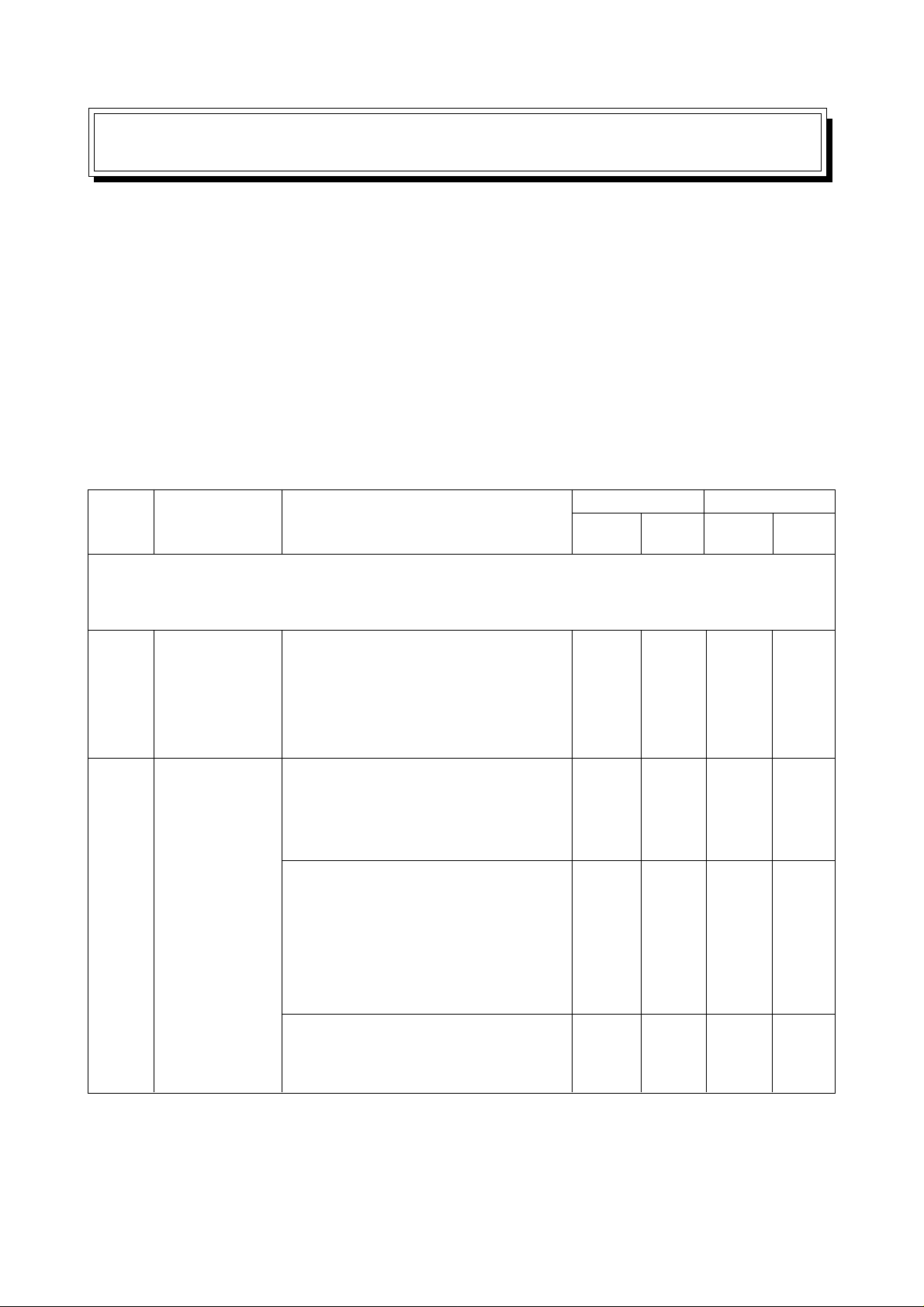
2. Outline of Main Operation Panel and NC Operation Panel
2-1 Operation by Using the Main Operation Panel and Sub-operation Panel
Group
No.
Note : When you operated a function which the specifications do not allow, the lamp of that push
button switch blinks, and the alarm lamp [8] and call light are turned on. Also, “NO
OPTION” is displayed on the CRT.
[1]
[2]
Mode selector
switches
Function
selector
switches (Push
a necessary
function switch
with the
SELECT”
switch
pressed.)
These are used for selecting
operation modes: “MDI”, “PROGRAM
EDITING”, “MEMORY AUTOMA TIC
OPERATION” and “TAPE
AUTOMATIC OPERATION”.
CANCEL Z... A machine lock
condition is applied to the Z axis only.
It is convenient if used for a program
test run.
MACHINE LOCK... Only a display
proceeds omitting axial moves of the
machine.
This function enables checking of
program coordinate values without
moving the axes.
DRY RUN... A manual jog feed rate
become valid instead of a feed rate
specified by the program
UseName
Operation method
Push
button
O
O
O
O
Lamp
O
O
O
O
Effective mode
Auto. Manual
O
O
O
O
O
O
1 - 1
Page 7

Group
No.
[3]
[4]
[5]
Name
Spindle rotation
effective key
Mode selector
switches
Program START
/ FEED HOLD
switches
Use
These push button switches start
and stop the spindle.
(It is necessary to specify a spindle
speed in advance.)
These are used for selecting
operation modes: “FEED”, and
“ZERO RETURN”.
FEED... This mode enables a
manual continuous feed. A feed axis
and its direction are selected by the
axis move push button switches [6],
and a feed rate by the FEEDRATE
[19] switches. Rapid traverse is
available by the rapid traverse
button.
RAPID... This mode enables a rapid
traverse. A rapid traverse axis and
its direction are selected by the push
button switches [6] and a rapid
traverse rate (override) by the
RAPID OVERRIDE push button
switches [17].
ZERO RETURN... This mode
enables zero return. For an axis to
be returned to the zero point, select
with the push button switches [6].
For a feed rate, an override of 25%
is applied.
When zero return is completed,
green lamp at [6] is lighted up, from
the blinking state.
START... IN the AUTO or MDI mode,
this push button switch start the
program. While this push button
switch is pressed and the program is
running, a lamp located above lights
up.
Operation method
Push
button
O
O
O
O
O
O
Lamp
O
O
O
O
O
OO
Effective mode
Auto. Manual
O
O
O
O
O
1 - 2
Page 8

Group
No.
[5]
[6]
[7]
[8]
Name
Program
START / FEED
HOLD switches
Axis move
switches
Initial position
check
Status display
lamp
Use
FEED HOLD.. This push button
switch suspends a program’s
progress. An axis being operated
stops and a red lamp located above
lights up. During operation by an
auxiliary command (M, S or T), the
program’s progress stops after
executing the remaining action of
respective command.
These push button switches move
the X, Y, Z and A (optional) axes
respectively.
Axis selection and its moving
direction abide by the indication
given on the respective push button
switches.
For a feed rate, select among the
FEEDRATE switches [22].
When executing rapid traverse, push
the rapid traverse button at the some
time.
APC INITIAL POSITION... This lamp
indicates that each machine section
is located at its specified position,
when executing an automatic. pallet
change (APC) command.
ATC INITIAL POSITION... This lamp
indicates that each machine section
is located at its specified position,
when executing an automatic tool
change (ATC) command. During T
cycle operates, this lamp lights up.
ALARM ... A red lamp lights up when
an alarm occurred.
PROGRAM STOP... When M00 or
M01 is executed during operation in
an automatic mode, a red lamp lights
up. It is lit off by starting or
continuing the program.
Operation method
Push
button
O
Lamp
O
O
O
O
O
O
Effective mode
Auto. Manual
O
O
O
O
O
O
O
1 - 3
Page 9

Group
No.
[9]
[10]
[11]
[12]
Name
Automatic
power shut-off
switch
Call right off
switch
Work setter
Safety check
Use
This makes the automatic power
shut-off function effective. After
machining cycle is completed, the
power is automatically shut-off by
M30 when no pallet exists.
This switches off the lighting call
light (yellow lamp melody horning.
Makes the following functions
effective, making use of a reference
touch tool
TOOL SETTER... Measures a tool
length and a tool diameter and
automatically sets their offset
amounts in the offset memory.
REF. SURFACE, REF. HOLE ...
Measures the coordinate system
shift amounts of the reference
surface and hole against the
machine coordinate system and
sets them in the coordinate system
shift memory.
COORD ALIGN... By measuring 3
points on the orthogonal or jig
located on the X-Y plane,
differences in rotation angle with the
X and Y axes are calculated and
stored, thus compensating X-axis
and Y-axis program coordinate
values.
Measure a machining tool length by
the 1st program start. Measure the
workpiece at an actual machining
position with the reference touch
tool mounted to the spindle by the
2nd program start. A workpiece-tool
interference check is made by Zaxis approach (G00) command,
adding the tool offset amounts used
for these two information.
Operation method
Push
button
O
Lamp
O
O
O
O
O
O
O
O
Effective mode
Auto. Manual
O
OO
O
O
O
1 - 4
Page 10

Group
No.
[12]
[14]
[15]
[16]
Name
Safety check
Override
Feedrate
override
switches
Spindle
override
switches
Use
TOOL LENGTH... Measures and
stores the length of the tool used for
an actual machining program.
COLLATION... Sets the Z axis to a
machine lock state, operates the
machine with an actual machining
program and checks whether there
is an interference between the
workpiece and tool when Z axis
approaches.
MEMORY... Memorizes optimum
override values (feed rate, spindle
speed) found in trial cutting, etc.,
making them corresponding to the
tools used.
AUTO. ... The override values
memorized are automatically input
to a program.
These push button switches apply
an override (ranging from 0 to
200%) to a feed rate in automatic
(cycle) operation. During a canned
cycle for tapping, the override is
ignored, resulting in 100%.
These push button switches apply
an override (ranging from 50 to
150%) to a spindle speed command.
Operation method
Push
button
O
O
O
O
Lamp
O
O
O
O
(Rotary switch)
(Rotary switch)
Effective mode
Auto. Manual
O
O
O
O
O
OO
1 - 5
Page 11

Group
No.
[17]
[18]
[19]
[20]
Name
Rapid override
switches
Conveyor
switch
Work light
switch
Coolant
switches
Use
These push button switches apply
an override (ranging from 0 to
100%) to a specified rapid traverse
rate. When the power is turned ON,
the override value becomes less
than 25%. In the manual operation,
the rapid traverse rate becomes
0~25%.
Note)The manual feed is not
available in 0%.
This push button switch runs the
chip conveyor.
This push button switch turns on a
work light.
These push button switches work
various kinds of coolant indicated
on them respectively. Each kind of
coolant can be turned ON/OFF
manually even during automatic
operation.
Operation method
Push
button
Lamp
(Rotary switch)
O
O
O
O
O
O
Effective mode
Auto. Manual
O
O
O
O
O
O
O
O
1 - 6
Page 12

Group
No.
[21]
[22]
[22]
[24]
[25]
[26]
[27]
Name
Feedrate
switches
Optional block
skip
Restart of
block
Power
Standby
Emergency
stop
(Main/Suboperation
panel)
Memory
Use
These push button switches select a
manual jog feed rate between 0 mm/
min and 5,000 mm/min.
(In case of the A-axis, it becomes
between 10 deg/min and 1,400 deg/
min.)
This switch makes the block skip
function command by program
effective. During programming, the
slash “/” used.
The RESTART OF BLOCK becomes
effective by pressing this switch and
the indication lamp lights up. This
becomes ineffective by repressing
this switch and the indication lamp
goes out. When the RESET OF
BLOCK is not provided as option,
this switch becomes ineffective and
the indication lamp puts out.
Through designating a sequence No.
that is not restarted by this functions,
the machining can be restarted from
that block.
ON ... turns on the main power to the
NC unit.
OFF ... Turns off the main power.
Drive preparation state as for the NC
unit to make the machine ready for
operation.
Stops the machine completely. All
motors are stopped and the NC unit
is reset.
LOCK... Protects the information
stored in the NC unit. Normally, shift
this switch to “LOCK”.
Operation method
Push
button
Lamp
(Rotary switch)
O
O
O
O
O
O
O
O
O
(Key)
Effective mode
Auto. Manual
O
O
O
_
_
_
O
_
_
_
O
O
1 - 7
Page 13
Group
No.
[28]
[29]
Name
Memory
Speed meter
Use
WRITE ... Shift this switch to
“WRITE” when writing or correcting
memory information.
Indicates a spindle speed.
Operation method
Push
button
Lamp
(Key)
(Meter)
Effective mode
Auto. Manual
O
O
O
[30]
[31]
[32]
[33]
[34]
[35]
Load meter
Tool clamp/
unclamp
Optional stop
Single block
Program restart
Manual pulse
generator
(Portable)
Indicates a spindle load to a motor’s
rated power in terms of percentage.
CLAMP ... Clamp a tool to the
spindle.
UNCLAMP ... Unclamp the spindle
tool. When the tool is unclamped, a
yellow lamp lights up and you
cannot run the spindle.
When M01 is commanded in the
tape, tape operation stops after all
the commands in the block are
completed. The indication lamp
lights up. This is released by
repressing the START button and
indication lamp puts out.
Program commands are executed
one block by one block. However,
canned cycles are executed one
cycle by oneb cycle.
The program restarts.
The indication lamp lights up. This
is released by repressing the button
and the indication lamp puts out.
Get the handle mode by the push
button and select the feed axis by
the rotary switch. For a feed rate,
you can select 1 pulse/graduation
(1/1), 10 pulses/graduation (10/1)
and 100 pulses/graduation (100/1).
Since it is portable, you can draw it
out to a convenient position for use.
For inch specifications, you can
select 1/1, 10/1 and 50/1.
(Meter)
O
O
O
(Toggle
switch)
O
O
O
O
O
O
O
O
O
O
O
O
O
O
O
1 - 8
Page 14

Group
No.
[36]
[37]
[38]
[39]
[40]
[41]
Name
State OK
indication
Cutting monitor
Cutting monitor
Block skip
AIR BLOW
Magazine
rotation (ATC)
Use
Information such as mode, override,
interlock, and spindle tool No.
necessary for machining can be
monitored.
The screen of the cutting monitor
can be monitored.
Monitoring data is automatically set
by the “AUTOMATIC SETTING”
teaching cutting data.
Select switch
INEFFECTIVE ... makes the cutting
monitor function ineffective.
EFFECTIVE ... makes the cutting
monitor function effective.
This makes the block skip 2~9
effective.
“/(2~9)” is used in the program.
Tool nose Air is spouted out from
the nozzle directed to the
tool nose
Through Air is spouted out from
the through coolant
nozzle.
The ATC magazine rotates to index
tools.
Forward rotation: CW
Reverse rotation: CCW
Operation method
Push
button
O
Lamp
O
(Select switch)
O
O
O
O
O
O
O
Effective mode
Auto. Manual
O
O
O
O
O
O
O
O
O
1 - 9
Page 15

Group
No.
[42]
[43]
[44]
Name
Manual
indexing
ATC initial
position return
Auto door
Use
Replacement of tools can be done
even when automatic operation is
going on.
ON ... “FORWARD” and
“REVERSE” buttons are effective.
OFF ... The above buttons are not
effective. To switch off manual
interrupt, keep pressing on the
“OFF” switch for at least 3 seconds.
This is a push button for making the
restoration easy after emergency
stop or power failure etc. during
ATC.
OPEN ... The door is opened.
CLOSED ... The door is closed.
Operation method
Push
button
Lamp
OO
O
O
O
Effective mode
Auto. Manual
O
O
O
[45]
DOOR
INTERLOCK
‘‘Effective’’ : Interlock of door
open becomes effective.
‘‘Ineffective’’ : Interlock of door
open becomes ineffective.
(Key switch)
O
O
1 - 10
Page 16
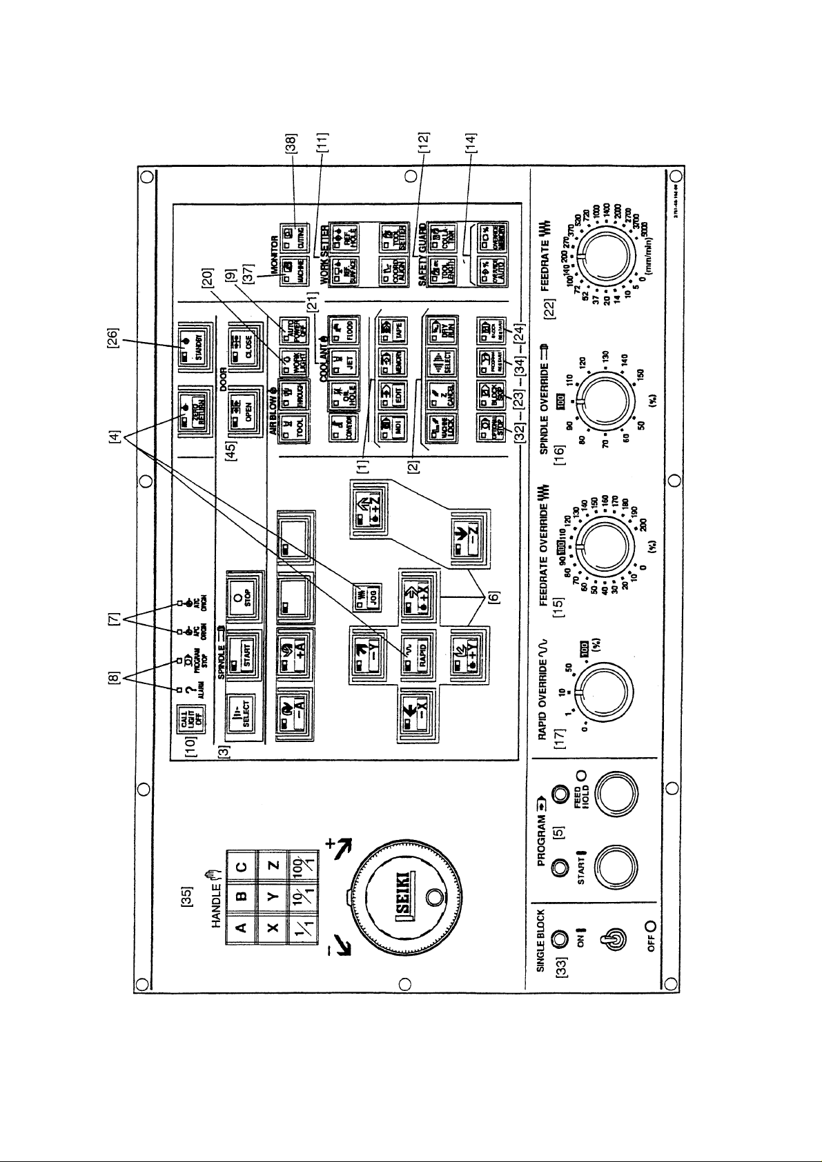
Main operation box (I)
[41]
1 - 11
Page 17
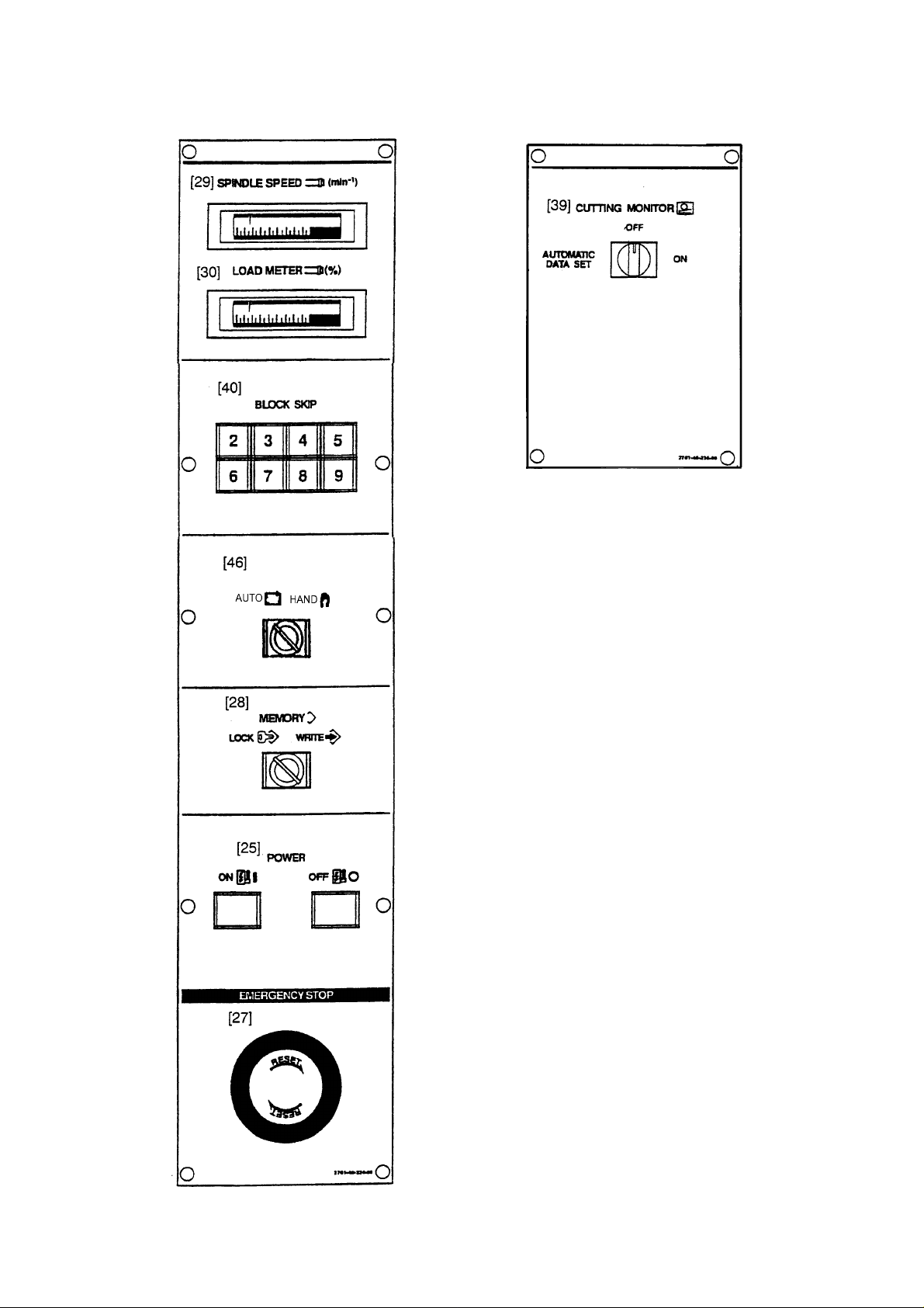
Fig.4-2 Main operation box (II)
1 - 12
Page 18
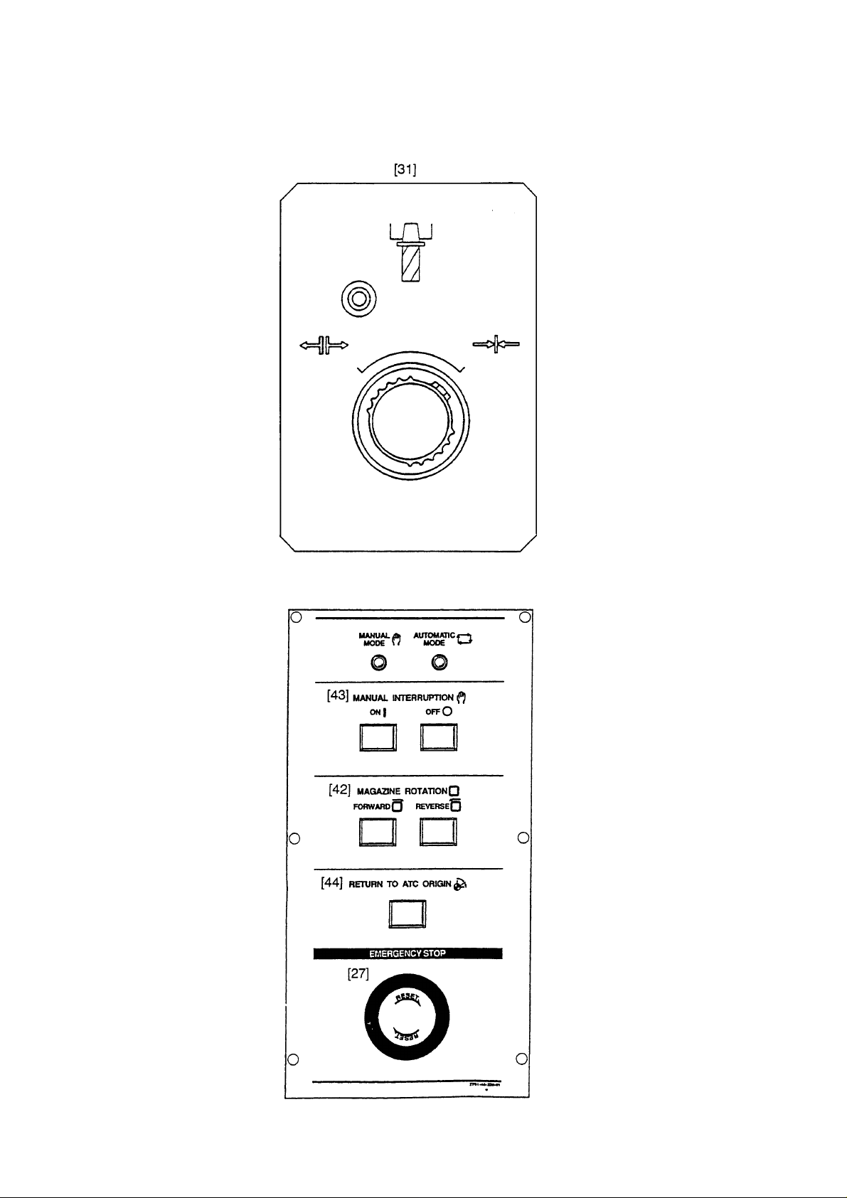
Auxiliary operation box (I)
Spindle tool clamp/unclamp
Auxiliary operation box (II) — ATC magazine
1 - 13
Page 19
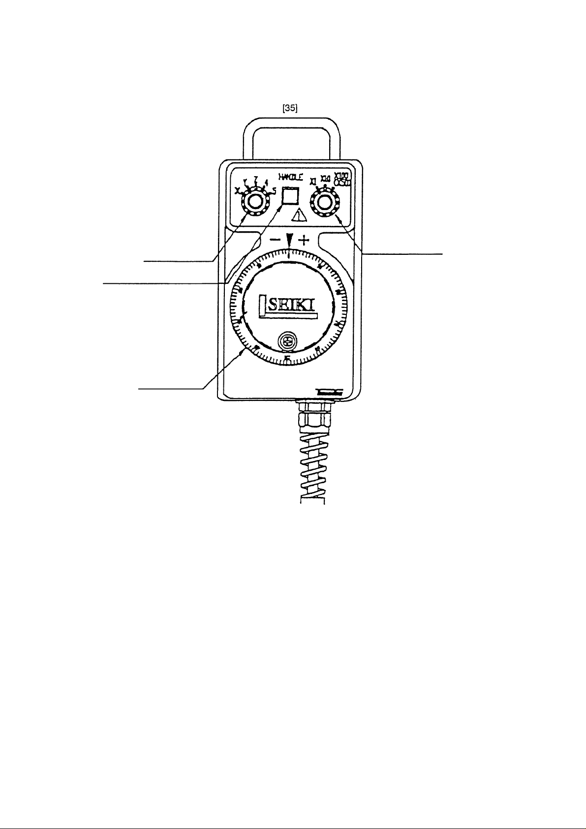
Handle operating panel
Axis selection
Handle mode selection
Magnification of
handle
Manual pulse
generator
1 - 14
Page 20
2-2 NC Operation Panel
1 - 15
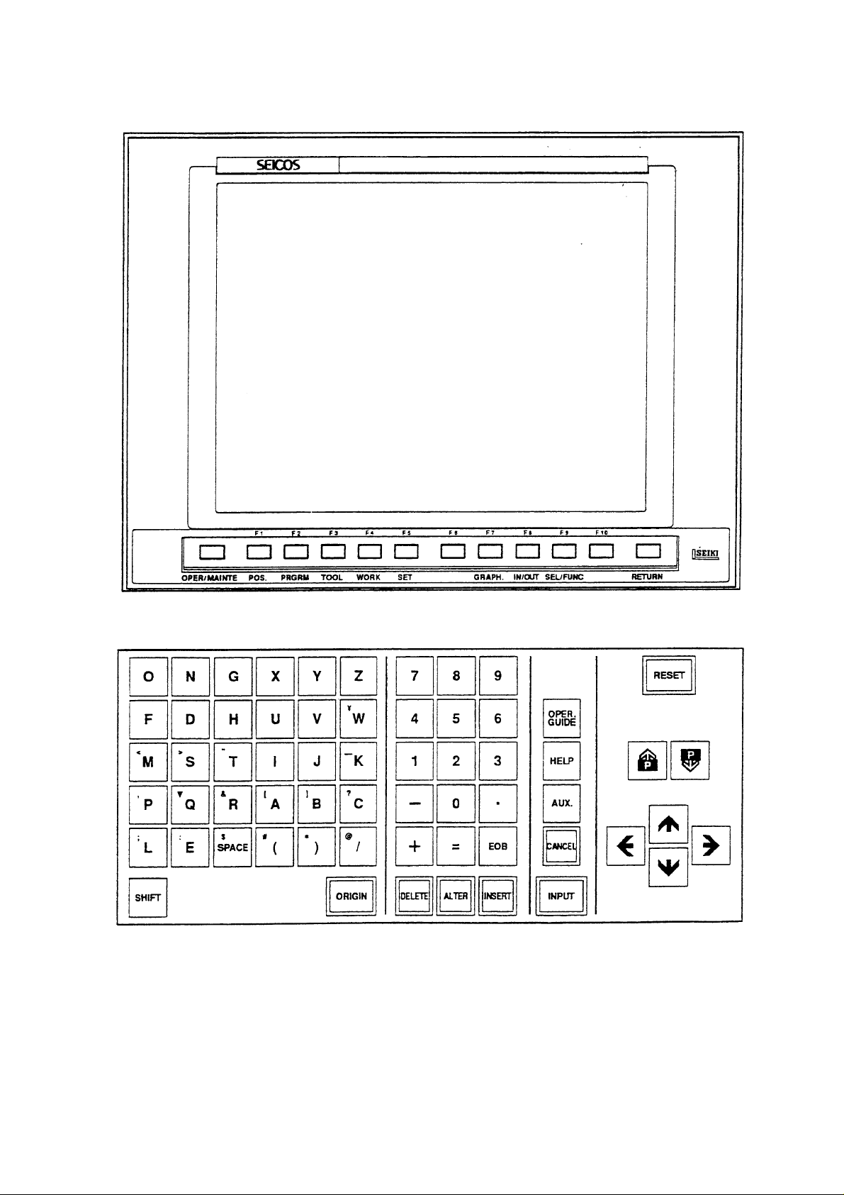
Page 21
NC Operation Panel
1 - 16
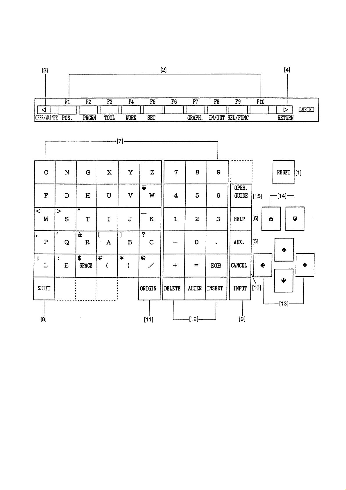
Page 22
NC Operation Keys
No.
[1]
[2]
[3]
[4]
[5]
[6]
[7]
[8]
[9]
[10]
[11]
[12]
[13]
[14]
[15]
Name
RESET key
Function keys
OPER/MAINTE
RETURN key
AUX. Key
HELP key
Address and Numerical
keys
SHIFT key
INPUT key
CANCEL key
ORIGIN key
DELET ALTER and INSRT
keys
Cursor move key
Page key
OPER. GUIDE
Description
Press this key when resetting the CNC unit in order to reset
an alarm so on.
When the function menu is displayed at the bottom of the
CRT, there are the keys to select the menu. When the
menu is not displayed, they serves as the keys to select the
Position, Program, Tool, Work Coordinate, Setting, Plot and
I/O screens. Press the F9/SEL/FUNC key when displayed
the function menu at the bottom of the CRT.
Press this key when displaying the PC, Alarm or
Maintenance screen. Pressing it once displays the function
menu at the bottom of the CRT, and pressing it again
erases the menu.
Press this key when you want to return to the Overall
screen.
Used to input the alphabet, numbers, etc.
There are some address keys which have 2 characters
marked on them. If you press the address key after the
SHIFT key, upper left character is input.
If the address or numerical key is pressed, it is input into
the key input buffer once, and then, displayed on the CRT.
Press the INPUT key when actually setting the data input
into the key input buffer.
Press this key when deleting the characters or symbols
input into the key input buffer.
This key is used to clear the Plot screen.
Used to perform deletion, alteration and insertion in editing
the program.
The alter key is also used for restoring F menu screen after
having selected an item on the F menu.
There are 4 keys which are used to move the cursor up/
down and right/left.
There are 2 keys which are used to page in the forward and
backward directions.
1 - 17
Page 23

3. Operational Procedures
3-1 When Starting the Machine
(1) Turn on the supply power Switch.
(2) Turn on the power switch on the electric cabinets
(3) Press the POWER ON push button switch located on the upper part of the main operation
panel.
Caution
The main panel and NC cabinet are enclosed lest the open air should enter
directly. Therefore, do not leave each door open for a long time while the power
is turned on. Check on the display and that cooling fan motors inside and
outside the cabinet are started.
(4)
Release EMERGENCY STOP button on the main operation panel.
Press the STANDBY push button switch located of the main operation panel. (A green
(5)
lamp lights up.)
(6) Before starting daily operation, reciprocate the X, Y and Z axes several times. (When this
is done, be careful not to have the axes overtravelled.)
(7) Return each axis to the zero point (refer to the description for zero return). By performing
zero return, a basic machine coordinate system is set and stored stroke limits are made
effective.
(8) Turn on the conveyor switch.
Caution
Do not make operation under the state that massive chips are cast in the trough.
1 - 18
Page 24

3-2 Warming-up Operation of Spindle
3-2-1 Warming-up at the Time of Starting Daily Operation
Caution
It is necessary to keep the bearing lubrication in a good condition for getting the normal
spindle revolution. If the spindle is suddenly rotated at a high speed without warmingup, there is a danger of the oil film being cut and the bearing is burnt stuck. To have
the spindle operated correctly in full capacity, warming up operation is necessary of
which the following should always be practiced practice.
Warming-up before starting daily operation (30 minutes)
[1] 30% of maximum spindle revolution (10 minutes)
↓
[2] 50% of maximum spindle revolution (10 minutes)
↓
[3] 80% of maximum spindle revolution (10 minutes)
Practice warming in the order of [1] , [2] , [3] .
3-2-2 Warming-up When the Machine Was Not Operated for More Than One Week or
Longer
Caution
In case of starting the spindle of oil air lubrication, after it has not been used for more
than one week, warming-up must be practiced taking a longer time than usual, as oiling
into bearing is necessary. In this case, please make sure up practice warming-up
according to the following schedule.
1. #50 - Spindle of 10,000min
Warming-up after the spindle has not been used for more than
one week (minimum warming-up time 4 hours)
[1] By 2,500min
[2] By 5,000min-1 for 1 hour or longer
[3] By 7,500min-1 for 1 hour or longer
[4] By 10,000min-1 for 1 hour or longer
Practice warming in the order of [1] , [2] , [3] , [4] .
-1
↓
↓
↓
-1
specification (oil air lubrication)
for 1 hour or longer
1 - 19
Page 25
2. #40 - Spindle of 20,000min
-1
specification (oil air lubrication)
Warming-up after the spindle has not been used for more than
one week (minimum warming-up time 4 hours)
-1
[1] By 5,000min
for 1 hour or longer
↓
[2] By 10,000min-1 for 1 hour or longer
↓
[3] By 15,000min-1 for 1 hour or longer
↓
[4] By 20,000min-1 for 1 hour or longer
Practice warming in the order of [1] , [2] , [3] , [4] .
3-3 Zero Return Procedures
Be sure to perform manual zero return so that you may set the basic machine coordinate
system after turning on the power.
Display on the pushbutton for zero point direction of each axis flickers.
(1) Operate the mode switching push button for “Zero return”.
(2) Of the push button switches for the axis desiring “Zero return”, press the one with the origin
mark ( ).
(3) By the specified speed of the rapid feed override, the axis returns to the zero point in the
rapid feed speed, and stops at zero point. Then, the zero point position confirmation lamp
of the axis is lit on.
(4) When the lamp lights up, release the switch.
Even when unhanded during decelerated speed movement, the axis stops after zero point
is generated.
The above operations will complete zero return.
Caution
1. Make zero return operations for each axis one by one.
2. When the axis for which zero return is intended is already located close to the zero
point, move axis once to the opposite side of the zero point by about 50mm then
move it again to the direction of the designated zero return point.
1 - 20
Page 26

3-4 When Completing the Daily Operation
(1) Confirm that START display lamp on the main operation panel is lit off.
Press EMERGENCY STOP button on the main operation panel.
(2)
(3) Clean the machine.
(4) Release EMERGENCY STOP button on the main operation panel.
(5) Set operation preparation, and drive the conveyor.
(6) Stop the conveyor after all of cutting chips in the bed are discharged.
(7) Move each axis to the stop position.
X-axis ......... center of the stroke
Y-axis.......... center of the stroke
Z-axis.......... the head upward movement end
(8)
Press EMERGENCY STOP button on the main operation panel.
Press POWER OFF button of the main control panel to cut out the control device power.
(9)
(10) Cut out power of the high voltage control panel.
(11) Cut out supply power.
1 - 21
Page 27

4. Manual Operation
4-1 Each Axial Feed
— In case of manual jog feed —
(1) Select the operation mode selector push button switch “JOG”.
(2) Press the FEEDRATE push button switch to set an appropriate feed rate. Pressing the
manual jog feed push button switch for a desired axis, move the machine in a desired
direction.
When it comes to a specified position, release the switch.
(The machine moves only while the switch is pressed.)
Applications : • Warming-up operation
• When bringing close to the zero point
• When cutting by manual operation
• Work rearranging operation
— In case of handle feed —
(1) Select the operation mode selector push button switch “HANDLE”.
(2) Select an axis with the axis selector push button switch.
(3) With the manual handle, you can move the machine by 0.001 mm (0.0001 inch) per
graduation (when 1/1 is selected) or by 0.01 mm (0.001 inch) per graduation (when 10/1 is
selected).
Applications: • When moving the machine by a very fine amount, such as when setting
the zero point by centering a workpiece or fixture
4-2 Rapid Traverse
(1) While pushing the rapid traverse mode switch, press the push button switch for the axis
you want to move at a rapid traverse rate (rapid traverse is applied only while the push
button switch is pressed). At this time, an override of 0, 1, 10, 50 or 100% can be applied
to a specified rapid traverse rate.
(2) Releasing rapid traverse push button switch changes the rapid traverse to normal feed.
1 - 22
Page 28

4-3 Mounting and Dismounting the Tool
(1) Stop the spindle head at an arbitrary position.
(2) Select one of manual operation modes; JOG, RAPID, HANDLE or ZERO RETURN.
(3) Holding a tool firmly, shift to UNCLAMP the TOOL CLAMP/UNCLAMP selector push button
switch, which is located on the front of the spindle head, and press it.
When the tool has been mounted, if the push button switch is released, the tip of the
drawbar will push the pull-stud bolt, thus removing the tool from a spindle taper hole (hold
the tool firmly lest it should drop). While the tool is unclamped, the yellow lamp located on
the upper left part lights up.
(4) When mounting the tool, eliminate dust completely from the taper section of the tool shank.
Clean the spindle taper hole properly with an accessory cleaner.
(5) Insert the tool shank into the spindle hole, and shift the TOOL CLAMP/UNCLAMP selector
push button switch to CLAMP and press it. The tool is automatically mounted to the
spindle and the yellow lamp lights off.
1 - 23
Page 29

5. Manual Data Input (MDI) Operation
5-1 Each Axial Feed
(1) After pressing RETURN button to get the general screen, set the mode selection
pushbutton switch to [MDI].
(2) General (MDI) is displayed on the display unit.
(3) Select the axis, which you want to mode, with the address keys, and enter the sign and the
numerical value by the numerical keys then press the RETURN key.
Press the INSERT button.
(4)
(5) Repeating the steps (2) and (3), input one block worth of data.
(6) Press the PROGRAM START button.
5-2 Coolant
(1) After pressing RETURN button to get the general screen, set the mode selection
pushbutton switch to [MDI].
(2) General (MDI) is displayed on the display unit.
(3)
Press the address key M .
Enter 0 and 8 by operating the numerical keys then press the RETURN key.
(4)
(5)
Press the INSERT button, and then, the PROGRAM START button.
Coolant is discharged from the nozzle at the spindle head.
(6) If you give M09 by similar operation, the coolant will stop.
5-3 Spindle Speed Change and S pindle Revolution
(1) After pressing RETURN button to get the general screen, set the mode selection
pushbutton switch to [MDI].
(2) General (MDI) is displayed on the display unit.
(3)
Press the address key S .
Input the spindle revolution speed by the numerical keys then press the RETURN key.
(4)
(5)
Press the INSERT button.
(6) Similarly, input an M code for spindle forward revolution or reverse revolution.
(7) Press the PROGRAM START button.
(8) To stop the spindle, give M05 by similar operation.
Example
MDI → S → 1 5 0 0 → EOB → M → 0 3 →
INSERT → PROGRAM START
1 - 24
Page 30

5-4 Spindle Positioning
(1) After pressing RETURN button to get the general screen, set the mode selection
pushbutton switch to [MDI].
(2) General (MDI) is displayed on the display unit.
Press the address key M
(3)
(4)
Enter 1 and 9 by operating the numerical keys then press the RETURN key.
Press the INSERT button, and then, the PROGRAM START buttons, the spindle runs at
(5)
a low speed and stops at its home position.
1 - 25
Page 31

6. Registration of Program
There are following two methods to register a program into the NC unit.
1. Registration from an external input device
2. manual registration by the address/numeral keys
6-1 Registration from an External Device
1) Connect an input device RS-232-C terminal
and make a possible condition of
transmission.
2) Set a mode to [EDIT].
3) Set the memory key to [WRITE].
4) Press the function key
F8/IN-OUTPUT .
A right sketch is displayed.
5)
Press the F1/INPUT key.
• Start reading from the first EOB of the NC program and continue until the % code.
• The program No. is registered the 0 No. registered in the input device.
• Display at the program No. list after completion of reading.
• At the time of input, the ISO/EIA information is recognized automatically.
Note) If the program No. already registered is inputted, it becomes an alarm condition.
1 - 26
Page 32

6-2 Manual Registration by the Address/Numeral Keys
1) Set a mode [EDIT].
2) Set the memory key to [WRITE].
3) Press the F2/PRGRM key.
4) Key in a desired program No. and press the
INSERT key.
Example: 0 1 2 3 4 INSRT
5) Set the cursor to; by the cursor key.
1 - 27
Page 33

6) Input a program according to the order of
the NC program.
Example:
Data>G91 G28 X0;
The EOB key must be inputted at the
•
end of one block.
• Press the CANCEL key when the data
which has inputted want to be deleted.
A word deletes one by one.
G 9 1 G 2 8 X 0
EOB INSRT
7)
Press the RETURN key and return to the
initial screen after input of all program is
completed.
1 - 28
Page 34

7. Program No. Search
There are following two methods to search a program.
1. Search by key in a program No.
2. Search to utilize the program list.
7-1 Search by Key in a Program No.
1) Set a mode to the [MEMORY] or [EDIT].
2) Set the memory key to [WRITE].
3) Press the function key
F2/PRGRM .
4) Key in the program No. to be searched and
press the
Example: O 1 2 3 4
Calling up program is displayed.
key.
1 - 29
O 1 2 3 4
Page 35

7-2 Search to Utilize the Program List.
1) Set a mode to the [MEMORY] or [EDIT].
2) Set the memory key to [WRITE].
3) Press the function key
F2/PRGRM .
4) Press the F7/PROGRAM LIST key.
5) Set the cursor to the program No. to be
searched by the cursor key and press the
INPUT key.
Calling up program is displayed.
1 - 30
Page 36

8. Edition of Program
The keys to edit a program are as follows;
INSERT : Insert a content of key input after the cursor.
ALTER : Alter a content of key input at a section of the cursor.
DELETE : Delete a section of the cursor.
Use it deletion of program as well.
8-1 Preparation in Advance at the Time of the Edition of Program.
To edit a program, the following conditions should
be made.
1) Set a mode [EDIT].
2) Set the memory key to [WRITE].
3) Press the function key
F2/PRGRM .
1 - 31
Page 37

8-2 Search of Word
A word can be searched by the following method.
1) A method by means of the page and cursor
keys.
[1] Press the page key and display the
page to be edited.
[2] Press the cursor key and move the
cursor to the word to be edited.
• The cursor moves at a block unit by
the
• The cursor moves at a word unit by
the
2) A method by means of word or address
search.
Since a message is displayed as “Not found”
if it is not found, try it again.
[1] Word search, No. search
Key in the address and numerals to be
searched and press
Example: M06
keys.
keys.
key.
M 0 6
1 - 32
Page 38

When searching a section above the
current position of cursor, press the
key
[2] Block search
Check a word in a block and search a
block which contains a relevant word
only .
Key in all address and numerals of one
block then press EOB and key.
Example: When searching a block of
M06 T06;
M 0 6 T 0 6
EOB
Note)
The EOB should be inputted at the
end of a block.
8-3 Edition of Program
(1) Insertion of word, block
New word is inserted just after the word
currently located the cursor.
[1] Designate a word immediately
before a section to be inserted.
[2] Key in a new data to be inserted
then press the INSERT key.
Example: when inserting Y 100.0 after
X-250.0
Y 1 0 0 .
0 INSRT
1 - 33
Page 39

[3] When inserting one block, key in data
of one block and press EOB and
INSERT key.
1 - 34
Page 40

(2) Alteration of word
Alter a word, the cursor located currently, to
the new word.
Alteration is done by a word unit.
[1] Set the cursor to the word to be altered.
[2] Key in the new word then press the
ALTER key.
Example: Alter S1000 to S2000.
S 2 0 0 0
ALTER
After alteration
S1000 replaces S2000.
1 - 35
Page 41

(3) Deletion of word, block
A word currently located the cursor or a
certain boundary of a program can be
deleted.
(a) Deletion of word
[1] Set the cursor to a word to be deleted.
[2]
Press the DELETE key.
Example: When deleting Z-200.0
Set the cursor to Z-200.0
then press the
DELETE key.
After deletion
Z-200.0 is deleted.
1 - 36
Page 42

(b) Deletion of block
It can be deleted one block at a time.
[1] Set the cursor to the head of the block
to be deleted.
[2]
Press the EOB and DELETE .
Example: When deleting a block G04
X 10.0;
Set the cursor to G04 and
press the EOB and
DELETE key.
After deletion
The block G04... is deleted and
program moves upward.
1 - 37
Page 43

(c) Boundary deletion
Delete blocks after the cursor to before the
designated sequence No.
[1] Set the cursor to the head word to be
deleted.
[2] Key in the sequence No. just after the
last block to be deleted and press the
DELETE key.
Note) Search the sequence No. before
deletion and check how far is it
deleted.
Example: When deleting
S1000 M03;
~
G28 X0 Z0 M19;
Set the cursor to S1000 and press
N 3 DELETE key.
After alteration
The program
moves upward.
1 - 38
Page 44

8-4 Back Ground Editing
Generally, “Editing” means front side editing, however this editing could not watch contents of
program and also edition is not available while executing a program.
In fact, giving a possibility to edit a program while executing a program is a back ground editing.
• An editing is available to other than currently executing program.
• A program under back ground editing can not execute.
• Editing can be done both manual and automatic mode.
1) Turn the memory key to [WRITE].
2) Press the F2/PROGRAM key.
3) Press the
F2/BACK GRD EDIT key.
A title of the screen becomes a “Back
ground editing”.
1 - 39
Page 45

4) Search a program wanted to edit.
A procedure of search is exactly same
as a (front) editing.
Caution
Never execute a reset operation, since the machine will stops if reset is done during
machine operation at the time of back ground editing.
5) Execute edition of program.
A procedure of edition is exactly same
as a (front) editing.
1 - 40
Page 46

6) End of back ground editing
Press the F2/BACK GRD EDIT key.
[1]
A title of screen becomes a “Program”.
It becomes normal editing screen.
8-5 Copy of Program
A program being displayed can be copied on the
other number and displayed.
1) Display a program wanted to be copied.
2) Key in a new program No. and press
INPUT key.
Example: When altering to O2001
O 2 0 0 1 INPUT
1 - 41
Page 47

8-6 Editing Procedure of Range Designation (Expanded Tape Editing/Option)
Designate a range of program and this “Insertion”, “Deletion” or “Storage” can be done at the
program screen.
• Starting of range editing
Operation...... Press the F3/RANGE EDIT key.
The function changes into that for range editing.
• Designation of range
Operation...... Press the F4/RANGE SET key.
The cursor becomes a frame.
A cursor range increases by moving this. That is a range.
• Release a designation of range
Operation...... Press the F4/RANGE SET key and F3/EXIT key.
It becomes a normal cursor and a range is released.
• Storage of range
Operation...... Press the F5/RANGE STORE key.
A part of range is stored.
If a size of range exceeds 2,048 characters (approx. 5m), “Range exceeds a limit.” is
displayed and not stored.
It can be used by the range insertion at any time, since it is stored until a power turned
off.
• Insertion of range
Operation...... Press the F6/STORE→INSERT key.
Insert a part of storage after the cursor by storage of range.
• Deletion of range
Operation...... Press the F7/RANGE DELETE key.
A part designated by range is deleted.
If the size of range exceeds 2,048 characters (approx. 5m), a message “Range exceeds
limit” is displayed and the storing is ineffective.
While the source power is kept on, the stored data is maintained and the data is
available by F8/DELETE→INSERT whenever desired.
• Inserting deletion
Operation...... Press the F8/DELETE→INSERT key.
The portion stored by range deletion is inserted at the cursor position.
1 - 42
Page 48

8-7 Alteration of Word (Expanded Tape Editing)
At the program screen, search a designated word to be altered in the program and rewrite it to a
word to be altered.
There are following two methods for alteration of word.
1) Search one word each and alter if after confirmation.
2) Alter words collectively (or after words continuously with display an altering condition).
The words to be altered collectively are maximum 400,000 words.
A method to search a word is the same as the word search, words combined one character of
alphabet (or “#” mark) and numerals becomes the number search as words showing the numeral
value and recognize it with or without a decimal point.
For example, of changing “X.1” to “X.5”, a row of characters such as “X0.1”, “X0.100”, “X00.10”,
“X.1” or “X.100” which coincide with “X.1” as numeral value, become the object of alteration and
change all to “X.5”.
Also, if adding a “?” mark on the word to be changed as “X.1?” such as changing “X.1?” to “X.5”,
a row of characters “X.1” becomes the object of alteration, then “X1” becomes “X.5” and “X.100”
becomes “X.500”, however, “X.01”, “X0.100” and “X00.10” does not have the row of character
“X.1” so it does not become an object of alteration.
Outline of operation
Start alteration of word by pressing the F5/WORD CONVT. key.
[1]
INPUT in the order of a word to search and alter then a word to replace it.
If replacing word is blank, it becomes a deletion.
[2] When searching a word one by one, designate a searching direction by the cursor
and press the Y key if found a word to be altered.
[3] For altering a word contained in many places of the file collectively, designate the
searching direction by the function menu. Confirm that such overall alteration is
unmistakable, then press Y key.
Once word alteration starts, it goes on to the beginning or end of the file, depending
on the searching direction. For suspending the alteration,
Press the F5/EXIT key.
In case of the alteration of words collectively as mentioned item [3], alter it except a
row of characters in the comment. To change inside of comment, alter it by the
method [2].
,
1 - 43
Page 49

OPERATION MESSAGE
F5/WORD CONVT. ........................................ “INPUT a word to be altered.”
Input the word to be altered ........................... “Input the word to be altered.”
Input the word to be replaced ....................... “Alter word from....to....”
The words are to be searched by cursor using
keys. “Alter word from....to....”
... INPUT as it is blank ................................. “Delete a word......”
...Alteration of word will be completed even if pressing the CANCEL key from • mark.
...Designate a searching direction of word by
...If it is not found ........................................... “Not found”
...“Search by cursor
...If it is found ................................................. “Alter a word....to....”
...Alter by Y key.
F1/BLANKET ALL Regardless of cursor position, searching starts with the
F2/BLANKET BEFORE Searching takes place in the forward part following the
F3/BLANKET AFTER Searching takes place in the backward part preceding
, .”
program head.
cursor including the word with the cursor.
the cursor including the word with the cursor.
, key.
,
...By operating , keys collective alteration starts.
...Alteration is executed by pressing Y key.
When alteration has be completed ................ “Word replaced”
When the word is not found........................... “Not found”,
.............. “0 word replaced”
Press F5/EXIT key. ...................................... “Alteration suspended”
1 - 44
Page 50

8-8 Deletion of Program
There are following two methods to delete a program.
1. Delete it by the program list screen.
2. Delete it by key input at the program screen.
1) Deleting method by the program list screen.
[1]
Press the F7/ PROGRAM LIST key at
the program screen.
[2] Set the cursor at the program to
be deleted by the program list.
Press the cursor key.
[3] Press the DELETE key.
[4] Against a message “Is it all right
to delete?”, press the Y key if
you agree.
A program which is designated
by the cursor is deleted.
1 - 45
Page 51

2) Deleting method by key input
[1] Display the program screen.
[2] Key in the program No. to be deleted
and press the DELETE key.
Example: In case of deleting O100
[3] Against a message “Is it all right
to delete?”, press the Y key if
you agree.
A program keyed in is deleted.
3) Continuous deletion by Program No.
[1]
Press F7/PROGRAM LIST .
[2] Place the cursor at the Program No. to
be deleted then press the SPACE bar.
An asterisk marked at the head of the
Program Nos. selected.
Example: Screen display shown below
is the case of deleting
Program
Nos. O100, O111, O169, O200.
Press the DELETE key.
[3]
For deleting the entire program, press
ORIGIN and DELETE keys.
O 1 0 0 DELET
8-9 Arrangement of Program
When editing a program, a size of program becomes larger than actual size occasionally. In this
case, available memory can be increased a little by arrangement of program. This operation is
called “Condensation”.
Operation
... Confirm that it is in the editing mode, not background editing, and NC is in reset
condition. (When there is secondary series or background drawings, it must also
be in reset condition.)
Press the F1/CONDENSE key.
A comment message “Condensing program” appears on the display, then after a
while, it changes to “Condensation complete”.
It takes several seconds to several minutes to complete program condensation,
depending on the size of memory and the condition of memory usage. If any key is
touched during the midst of this process, the comment message “Condensing
program” disappears and the process is suspended.
1 - 46
Page 52

Caution
If source power is switched off during “Condensation”, the program is destroyed.
When a program is found to be abnormal, initialize the program memory, and input the
program anew.
8-10 Process After Edition
Press the RETURN key.
Return to the initial screen.
1 - 47
Page 53

9. Output of Program
NC program can be outputted to the external in/output equipment.
1) Connect an output device to the RS-232-C
terminal and make it ready.
2) Make a mode selection to [EDIT].
Press the function key F8/IN/OUT .
3)
Note) When “Dondon FD” is on the screen
display, press the
F5/DONDON FD COMPLETE
key, and get the “Data Output”
screen.
Refer to the instruction manual of output
device.
A right sketch is displayed.
1 - 48
Page 54

4)
By pressing F7/ LIST CHANGE , switch
over the screen display from “Program No.
List” to “Program No. Detail”.
• To select Program No.
Place the cursor at the Program No. to be
select then press the SPACE .
An asterisk is marked at the head of the
Program No. selected. When selecting all
programs, repeat pressing “ORIGIN”
several times until the mark “*” is
displayed.
Example: O5, O6, O7.
5)
Press the RETURN key after completion of
output and return to the original screen.
1 - 49
Page 55

10. Automatic Operation
10-1 When Machining the First Workpiece, Checking the Newly Created Program
(1) Go through the steps (1) through (5) mentioned in 4-6-2 “Program Memory Operation”
(2) Turn on the [SINGLE BLOCK] switch. (When this is done, it is recommended to set a
rapid override value to 10% for safety.)
(3)
Press the PROGRAM START button.
Check one block worth of functioning, press the PROGRAM START button again to
(4)
sequentially advance a program.
10-2 Program Memory Operation
Caution
Close the front door and the ATC magazine door.
(1) Check that the ALARM lamp on the main operation panel is not lit up.
(2) Check and correct tool length and tool compensation data, if necessary.
(3) Set the mode selector switch to “MEMORY”. For normal operation, at this time, turn
off the DRY RUN, OPTIONAL STOP, MACHINE LOCK, BLOCK SKIP and SINGLE
BLOCK switches, and set the FEEDRATE OVERRIDE, SPINDLE OVERRIDE and
RAPID OVERRIDE switches to 100%.
(4)
Press the RESET button on the setting operation panel.
(5) Call the PROGRAM AUTOMATIC to the display screen by pressing the
F2/PRGRM button to check the initial state.
WARNING
!
In order to suspend the machine durintg operation, press STOP button on the
operation panel or turn [ON] SIGNAL BLOCK switch.
In case of emergency, press the EMERGENCY STOP button to immediately stop the
machine on the operation panel.
1 - 50
Page 56

10-3 When Inserting Manual Operation in Automatic Operation
(1) Press the PROGRAM STOP push button switch (while program operation is suspended, a
red lamp lights up.) or suspend the machine operation by turnig [ON] SINGLE BLOCK
switch.
(2) Select the operation mode selector push button switch either [HANDLE] or [JOG] and
perform manual operation.
(3) On completion of manual operation, return the mode selection to [MEMORY].
(4) Press the PROGRAM START button to restart the program.
Caution
Even when the PROGRAM STOP button is pressed, the M, S and T functions
continue until their actions are completed. Manual operation is available only after these
actions are completed.
10-4 When Performing MDI Operation in Automatic Operation
(1) Turn on the [SINGLE BLOCK] switch on the operation panel.
(2) Shift the mode selection switch do [MDI] after the machine stops.
(3)
Press RETURN button to get the general screen.
(4) Enter necessary actions with the address keys and numerical keys, and press the
INSERT button.
(5)
Press the PROGRAM START button after confirming the data of one block has
been input.
(6) To restart the automatic operation, shift the mode selector switch to [MEMORY] or
[TAPE] and turn off the SINGLE BLOCK switch.
Press the PROGRAM START button.
(7)
Caution
1. When an auto command immediately before is a canned cycle and you specify an
action other than the canned cycle by MDI operation, be sure to specify a
necessary G code.
2. When MDI operation is inserted in the state mentioned in Note 1, you must specify
hole machining data preceding MDI insertion, if you want to execute the auto
command again.
WARNING
!
After you enter actions by MDI operation, if you forget to execute them (due to a certain
reason such as leaving a work site) and restart automatic operation, the machine
functions in an unexpected way and endangers you, because buffer contents for
automatic operation have been replaced with unexecuted MDI buffer contents. Be full
aware of it.
1 - 51
Page 57

11. Operation of Automatic Tool Changer (ATC)
1 1-1 Names of ATC Each Section
Bed
Magazine
Servo motor
(Magazine rotation)
Tool change position
Proximity switch
(Tool feed hand open/close)
Proximity switch
(Waiting grip, tool ready or not)
LS54A
Twin arms
Cum box
(Twin arms rotates,
goes up and down.)
Photo macro
(LS637A,
637B, 637C)
LS603A, 603B
Tool setting position
Tool feed hand
Air cylinder
(Hand forward and backward movement)
Proximity switch
(Hand forward and backward movement)
LS92A, 92B
Tool grip
Solenoid valve
(Backup pump)
SOL636
Solenoid valve
(Tool feed hand)
SOL603A, 603B
Solenoid valve
(Hand forward and backward movement)
SOL92A, 92B
Inverter motor
(Twin arms rotates, goes up and down.
Tool lock oil hydraulic)
1 - 52
Page 58

11-2 Explanation of Actions
ATC operates continuously according to command contents.
1. Change Spindle and Waiting Tool……M06 Operation
Note) (M1**) in the figures operates only at the maintenance mode.
1) Open the shutter, and move to the
spindle orientation Z-axis second
original point.
Z-axis second original point
Shutter closed
(M100)
2) Move to X-axis third original point (tool
change position).
Third original point position
4) Move to X-axis second original point, and
index magazine of waiting tool number.
Second original point
3) Tool change action (M117)
Tool loosened
Arm downward
movement
Arm rotation
Arm upward
movement
Tool fastened
5) Shutter is closed.
Shutter closed
(M101)
1 - 53
Page 59

2. Call Tool to Waiting Position………….T01~T20 (T30 Option)
Note) (M1**) in the figures operates only at the maintenance mode.
1) Index magazine of waiting tool number. 5) Index magazine of T code number.
6) Feed hand is closed (M102).
2) Feed hand is closed (M102).
3) Move feed hand to magazine side.
(M104)
4) Feed hand is open (M103).
7) Move feed hand to twin arms side
(M105).
8) Feed hand is open (M103).
9) Index magazine of spindle tool number.
1 - 54
Page 60

3. Return Waiting Tool to Magazine……….T00 Action
Note) (M1**) in the figures operates only at the maintenance mode.
1) Index magazine of waiting tool number. 5) Index magazine of spindle tool number.
6) Feed hand is closed (M102).
2) Feed hand is closed (M102).
3) Move feed hand to magazine side.
(M104)
4) Feed hand is open (M103).
7) Move feed hand to twin arms side
(M105).
8) Feed hand is open (M103).
1 - 55
Page 61

1 1-3 Rotation of Tool Storage Magazine (at Single Mode)
The magazine is rotated while the pushbutton switch on the ATC single operation panel is being
pressed. When requested pot No. comes close to the specified position, release the
pushbutton, which makes the magazine decelerate, position and stop.
1 - 56
Page 62

11-4 Attachment and Detachment of Tools
Attachment and detachment of tools are accomplished through the tool attachment/
detachment window on the right side of the machine. The procedures are as follows.
[1] Keep pressing manual indexing button “ON” on ATC control panel until the button is lit on.
[2] Index the magazine to be attached or detached to the tool attachment/detachment position.
(Operate until this stage, keep closing the tool attachment/detachment window.)
Tool attachment
[3] Align the tool holder V groove and the magazine grip.
(Refer to the next section for tool key grooving method.)
[4] Push a tool horizontally into the magazine side.
(Pay attention to the spring of the magazine clip section when pushing.)
Tool detachment
[5] Hold the taper section of the tool holder and the tool shank section firmly with both hands,
and pull them out horizontally towards you.
[6] Close the tool attachment/detachment window
[7] Press the manual indexing button “OFF” on ATC control panel for three seconds or more.
Magazine manual indexing is executed by normal/reverse rotation selection button on ATC
control panel. It rotates per pitch by inching operation, and rotates continuously by keeping
pressing the button.
Caution
When attaching and detaching, give full attention to edges of tools and weight for
safety operation.
Tool attachment/detachment
method Tool attachment/
detachment position
Tool holder V groove
Guide for attachment/detachment
1 - 57
Tool attachment/detachment window
Page 63

1 1-5 Relation Between Spindle Nose Key and ATC
When turning edges of tools which have directionality such a boring bar in the direction of key
of the magazine grip, the edges, attached to the spindle by ATC action, turn to the left from the
machine front.
Key of tool grip
Spindle center
Tool change diagram
View from spindle end face
Change position
Tool attachment/detachment
position
1 1-6 Attention When Using Oil Hole Tool
• When attaching an oil hole tool, attach it so that the pilot plunger (positioning pin) may
come in the direction of the key of the magazine clip.
• When using an oil hole tool, cutting chips attached to oil hole block side may cause
troubles in insertion and positioning of pilot plunger of a tool into block. Regardless of
manual or automatic operation, turn “ON” oil hole coolant, or blow down coolant tentatively
by M50 command before attachment. After cleaning the block like this, change tools.
* Be sure to use an oil hole tool exclusively for HITACH SEIKI VS50/60.
1 - 58
Page 64

1 1-7 ATC Program Operation
(1) Block operation by the program (automatic mode)
The ATC carries out the following block operations, depending on the program:
T ; Calls the tool No. from the tool magazine to an arm “standby
position”.
M06 ; Replace the tool in the spindle with that located at the arm standby
position.
T M06 ; Calls the tool No. from the magazine to the “spindle”. (ATC
canned cycle)
T00 ; Returns to the tool magazine the tool located at the arm standby
position.
(2) ATC Single Block Stop
When single block is on, ATC action by M06 goes on by each step shown in M06 action (1)
- (5) of ATC action explanation.
1 - 59
Page 65

11-8 Condition Check During ATC Execution
1) • Tool No. on the spindle
• Tool No. at the ATC arm standby position are displayed on the general screen.
2) • Tool No. commanded in a program is displayed on the commanded value screen.
How to display each screen is as follows:
1) How to display the general screen
When pressing the RETURN key, the general screen appears.
1 - 60
Page 66

2) How to display the commanded value screen
Display the general screen → Press the F1/POSITION key → Press the function key
F4/COMMAND VALUE for commanded values → The commanded value screen appears.
1 - 61
Page 67

12. Setting (Data)
12-1 Outline
Various setting data required to operate the machine can be set.
The setting (Data) screen is displayed by pressing the F5/SET key.
In this screen, parameters frequently used are classified together by item or purpose for easy
setting.
An option is not displayed if it is not provided.
Since it consist of several pages, change it by pressing the page key
corresponding a menu at the left side of the screen.
The number search also available.
Setting (Data)
or alphabetical key
(1) Display and setting
In case of a selection such as “Do/Don’t”,
you want.
Set the cursor by the cursor key and press the INPUT key.
Further, when the cursor key is pressed, it moves at the side of mark. The
HITACHI SEIKI’s standard is the left side.
Numeral data is set through the key input area. Needless to say, calculation and absolute/
increment value input are also available.
marks are on at the side of setting has done if
Caution
Input limit for writing key etc. is not applied on the setting screen is different from the
parameter screen, change it with fully attention by an operator himself.
1 - 62
Page 68

(2) Number search
Since all pages have serial number, a page or cursor can be moved at once by the number
search. A search executes by pressing a cursor key after inputting N and
following numerals.
Example N: Number = 12
(Move to No. 12)
N: Number = 1 + 10
(3) Setting method
1. Set the key switch for writing of
memory to “write side”.
2. Select the setting data screen.
Press the RETURN key.
Press the F5/SET key.
3. Set the cursor to the item to be
changed by the page and cursor key
or number search.
Press the page key and
display a section to be
changed.
(Move to No. 11)
N
or, input the setting number.
4. Key in a desired numeral and press
the INPUT key.
5. press the RETURN key and display
the initial screen after completion of
setting.
1 - 63
Page 69

13. Time Measuring, Data
Machining time and cutting time are displayed at the lower right of the general screen. It can be
displayed by pressing the RETURN key.
13-1 Time Measuring
Four type of time is measured at the lower right of the screen. It can be measured in the limit
of less than 10,000 hours.
Input in here execute by moving the cursor after pressing the F9/SEL/FUNC key
Example: (Hour/Minute/Second) = 0 (Set to zero)
(Hour/Minute/Second) = 1 (Input as 1:00:00)
(Hour/Minute/Second) = 1/2 (Input as 1:02:00)
(Hour/Minute/Second) = 1/2/3 (Input as 1:02:03)
(1) Prearrangement of completion
Advance notice of completion becomes effective when “SET END TIME” on the operation
panel of the machine is “ON”.
A time of a prearrangement of completion is a time from start to the time of a advance
notice of completion at the automatic operation.
If an operator inputs a time of a prearrangement of completion of a program, inform it by
call light when a machining time reaches to the prearrangement of completion.
1 - 64
Page 70

(2) Machining time
Accumulate a time during machining. (A time of the start lamp is being on.)
(3) Cutting time
Accumulate a time during cutting feed. (A time during cutting feed by G01, G02 or G03)
(4) Lap time
Measure a lap time between a tool and tool. At the time of tool change set it to zero
automatically. Measurement does not execute while the NC is stand by condition.
13-2 Date and Time
The date and time is displayed by the clock builted in.
The date shows by A.D. and time shows by 24 hours. (1 p.m. is 13 hours.)
Since it is backed up by a battery, it moves even if the power is turned off.
Do not change it unnecessarily, however, if discrepancy of the time has occurred from one cause
or another, it should be set correctly because it uses at the time of periodical check.
1 - 65
Page 71

14. Animated Drawing
14-1 Outline
When the F7/GRAPH key is pressed, the animated drawing screen is displayed.
Animated drawing of a locus of a tool is executed here. Also, the following data are displayed for
the reference of animated drawing.
Animated drawing plane of parameter
Tool tip position
Rotation S, Feed F, Tool command T
Machining time, Cutting time
List of programs currently under execution
A locus is drawn based on a value of the tool tip coordinate system. Since a moving point becomes
unclear if drawing consist of plenty of lines, a tip is expressed by a small point.
Normally, synchronous drawing is displayed. For pre-processing drawing, press the
F9/PREVIEW key and get the display of the list of function keys for pre-processing drawing.
Then, press the F3/PREVIEW START key and pre-processing drawing will start.
Pressing the F2/AUTO RANGE key, pre-processing drawing will start and the drawing range is
set in such a way that the locus of the cutting feed is properly shown within the frame of the screen
when drawing finishes.
For canceling the display of a drawing, press the ORIGIN key.
Following setting can be done for drawing. Refer to the following item for details.
Selection of drawing plane
1 - 66
Page 72

Indication of rotating angle (Horizontal, Vertical)
Drawing zone (Maximum, Minimum)
Indication of drawing for each tool (Color designation)
Selection of cutting feed line
Selection of rapid traverse line
Color designation for drawing dot lines.
14-2 Drawing Parameter
The drawing parameter screen is overlapped with the drawing screen when pushing the
F1/GRAPHIC PARAM. of the drawing screen ( F7/GRAPH. ).
By pressing the F2/RANGE key, the display changes into the range setting screen.
By pressing the F3/PLANE key, the display of plane setting screen can be called up.
GRAPHIC parameter (Range setting) GRAPHIC parameter (plane setting)
Setting parameter for drawing: Move the cursor by cursor keys to the parameter
column to be set. Brief explanation is displayed on the
explanation column.
[Range setting]
(1) Drawing zone
Set the maximum or minimum value of each axis to draw.
Center coordinate (mean value of max. or min. value) and magnification (Max, and min.
value are shown in the screen.) are decided.
Input a coordinate value (work coordinate) in the key input area and decide it by pressing
the INPUT key.
In this case the maximum value should be set larger than the minimum value.
1 - 67
Page 73

(2) Drawing for each tool
Change a drawing color at each time of tool change.
Applicable color are up to six and return to the beginning color beyond it.
Execute the setting by the color designation.
marks are on at the side of setting has done. Change is decided by pressing the
INPUT key after selection by cursor key .
(3) Cutting feed line
Designate the type of the cutting feed line.
marks are on at the side of setting has done. Change is decided by pressing the
INPUT key after selection by cursor key .
(4) Rapid traverse line
Designate the type of the rapid traverse line.
marks are on at the side of setting has done. Change is decided by pressing the
INPUT key after selection by cursor key .
(5) Color designation
Set a color to be changed when the drawing for each tool is effective.
Only this color designation change is available later.
Select a color designation by the cursor key
and designate a tool by the cursor key
.
Decide it by pressing the INPUT key after inputting a numeral from 0 to 7 according to the
instruction.
(6) Color of Drawing Point
Designate color of the first point of drawing.
Select color of drawing point by cursor for setting.
Select the figure between 0 and 7 according to the explanation, and press
INPUT for deciding.
[Plane Setting]
(1) The drawing plane is designated. A plane is selectable from the following 5 options.
1 - 68
Page 74

Enter numeral 0-4 (according to the above illustrations), then press the INPUT key.
The selected plane is displayed on the screen.
A numeral with minus sign is ineffective, which gives no drawing plane on the screen.
(2) Rotation Angle
This is effective for drawing plane “0” (3-axis expression) only.
Key in the value of angle in the appropriate area provided for entering, then press the
INPUT key.
(a) Horizontal rotation angle
The rotation angle on the horizontal plane is designated within the range of ±180
degrees by step of 1 degree.
Example: The case of vertical rotation angle = 90° degrees in (XYZ).
(b) Vertical rotation angle
Angle is adjusted to the inclination of the vertical axis.
Example: The case of horizontal rotation angle = 0° degrees in (XYZ).
(3) Designation of Axis
The axis used for the drawing is designated.
Enter the name of axis desired to be designated. Axis name with minus sign is allowed.
1 - 69
Page 75

15. Parameter Setting
The parameter setting is executed by the following
procedure.
1) Set the mode to the [MDI].
2) Set the memory key to the [Write].
3) Make effective the “Parameter rewriting” of
the setting (data).
[1]
Press the F5/SET key.
[2] Set the cursor to “7. Rewriting of
parameter” by the cursor key
[3] Move the mark to the “Valid” by the
cursor key
INPUT key.
The parameter writing is ready.
and press the
.
1 - 70
Page 76

Press the RETURN key and make the
4)
initial screen.
5) Press the OPER/MAINTE key and
then the F4/SYSTEM key.
It becomes the menu screen.
6) Set the cursor to “1. PARAMETERS” by
cursor key
INPUT key.
The screen changes to the parameter
setting items.
and press the
1 - 71
Page 77

7) Select an item to be changed by the cursor
key and press the INPUT key.
The parameter list is displayed.
If the setting is “Selected”, it displays as the
right side sketch for example.
8) Set the cursor to the parameter No. to be
changed by the page key
key
9) Change the parameter.
The parameter has two types as a data
indicates by 0 or 1 and numerical data.
(a)
or direct call by N etc.
A data indicated by 0 or 1 .
[1] Set the cursor to a bit to be changed
by the cursor key .
[2] Key in 0 or 1 and press the
INPUT key at the condition of
display as “P: ABS=” the lower left of
the screen.
Move the cursor display for each bit
to set.
or cursor
1 - 72
Page 78

[3] Return the cursor display to the
“Number” column by the cursor key
after completion of setting.
The parameter can be changed by
direct input of hexadecimal number.
(b) A data indicated by numerals.
[1] Key in the new numerals and press
the INPUT key at the condition of
display as “P: ABS=” the lower left
of the screen.
10) Procedure after setting
[1]
Press the RETURN key and make the
initial screen.
Press the F5/SET and display the
[2]
“Setting (Data)” screen.
[3] Make the “Rewriting of parameter”,
“Invid” by the cursor key .
[4] Set the memory key to “Lock”.
1 - 73
Page 79

16. Operations Concerning W-Setter
16-1 Outline
W-setter enables automatic setting of tool offset amount and work
origin offset amount by a simple manual operation with a touch sensor
mechanism.
Work setter (Setting of work origin offset amount)
Reference surface
Reference hole
Coordinates modification
Tool setter (Setting of tool offset amount)
16-2 Input Signal and Various Operations
Work setter reference surface selection button ........ WSS
Work setter reference hole selection button ........ WS H
Work setter coordinates modification selection button ........ WSC
Tool setter selection button ........ OFH
Touch sensor signal ........ SKIP
(1) Work setter reference surface (2) Work setter reference hole
Touch probe
X, Y-axis
coodinate
(4) Tool setter tool length
Z-axis coordinate
(boring)
Tool lengtht
(3) Work setter coordinates modification
* Example of touch sensor
X-axis coordinate
Y-axis coordinate
X-axis
coodinate
Coordinate rotation
Y-axis coodinate
use on table
Reference block
(5) Tool setter tool length diameter
* Example of touch sensor use on table
Reference
block
angle (R)
Tool length
Tool diameter
Tool diameter
1 - 74
Page 80

16-3 Operation for Setting of Work Setter Reference Surface
(1) Execute reference point return of 3 standard axes manually. Attach the touch probe to the
spindle.
(2) In the manual mode, have the work setter reference surface screen ON.
→ Work coordinate (compensation) screen (Fig. 1.8) is selected automatically.
(3) Select the work coordinate desired to be set by operating the page key and cursor keys.
(4) Have the touch probe come into contact with the reference surface by the manual feed
operation.
(5) The system automatically judges the axis of which the touch sensor signal comes on,
calculates the work origin offset amount and the data is automatically written in.
(6) When the setting of all the necessary offset amounts for the work origin is completed, let
the work setter reference surface screen OFF.
(Note 1) The touch probe data used for calculating offset amount is to be set with
parameter (No.6252~6255) in advance.
Fig.1.8 Screen Display on Work Coordinate
1 - 75
Page 81

16-4 Operation for Setting of Work Setter Reference Hole
(1) Execute reference point return of 3 standard axes manually. Attach the touch probe to the
spindle.
(2) In the manual mode, have the work setter reference hole screen ON.
→Work coordinate (compensation) screen (Fig. 1.8) is selected automatically.
(3) Select the work coordinate desired to be set by operating the page key and cursor keys.
(4) Have the touch probe come into contact with an arbitrary point of the reference hole by the
manual feed operation.
→The system memorizes the position of the main/auxiliary axis where the touch sensor
signal became ON, and displays a commentary message to be ready for the measurement
of the second point.
(5) Have the touch probe come into contact with the second measuring point of the reference
hole.
→The system memorizes the position of the second point and displays a commentary
message to be ready for the measurement of the third point.
(6) Have the touch probe come into contact with the third measuring point of the reference
hole.
→The system memorizes the position of the third point and calculates the center of the
three points and determines the work origin with which the work origin offset amount is
written in automatically.
→Now ready for the measurement of the first point of another reference hole.
(7) When the setting of all the necessary offset amounts for the work origin is completed, let
the work setter reference hole screen OFF.
*
After the procedure (5) in the above, when the F2/2-POINTS MEAS. key is pressed, the
system calculates the midpoint of the two points and the work origin offset amount thus
calculated is written in automatically. In this case, the groove width is displayed on the
right of the commentary message.
* When measurement in the Z-axis direction is made, the system calculates the third axis
work origin and the offset amount, which is written into the system automatically.
(Note 1) When the system is reset in the midst of the setting operation (during 2nd or
3rd point is being measured), the system returns to the initial status (the status
to be ready for the 1st point measurement).
(Note 2) The mutual distances between the 3 points is short against the parameter
setting (No.6257), the measurement cannot be made and a commentary
message is displayed accordingly. By resetting, the status is released and the
system is initialized.
(Note 3) When you only wish to know hole diameter or boss diameter without rewriting
the work origin offset amount, press the F3/3-POINTS MEAS. key after the
procedure (5) in the above then have the probe contacted to the third point.
1 - 76
Page 82

By this key operation, the hole diameter or boss diameter is displayed on the
right of the commentary message.
(Note 4) The touch probe data used for calculating work origin and offset amount is to
be set with parameter (No.6252~6255) in advance.
16-5 Operation for Setting of Work Setter Coordinate Modification
(1) Execute reference point return of 3 standard axes manually. Attach the touch probe to the
spindle.
(2) In the manual mode, have the work setter coordinate modification screen ON.
→Work coordinate (compensate) screen (Fig. 3.1) is selected automatically.
(3) Select the work coordinate desired to be set by operating the page key and cursor keys.
(4) Have the touch probe come into contact with an arbitrary point of the reference surface by
the manual feed operation.
→The system memorizes the position of the X, Y-axis positions where the touch sensor
signal became ON, and displays a commentary message to be ready for the measurement
of the second point.
(5) Have the touch probe come into contact with the second measuring point of the reference
surface.
→The system memorizes the position of the second point and displays a commentary
message to be ready for the measurement of the third point.
(6) Have the touch probe come into contact with the third measuring point on the surface
intersecting rectangularity.
→The system memorizes the position of the third point, based on which it calculates the
position of the corner and the coordinate rotation angle thereby the work origin offset
amount is written in automatically.
→Now ready for the measurement of the first point of another reference surface.
(7) When the setting of all the necessary offset amounts for the work origin is completed, let
the work setter coordinate modification screen OFF.
*
After the procedure (5) in the above, when the F2/2-POINTS MEAS. key is pressed,
the system calculates the coordinate rotation angle only and the work origin offset
amount is written in automatically.
* When measurement in the Z-axis direction is made, the system calculates the Z-axis
work origin offset amount, which is written into the system automatically.
1 - 77
Page 83

(Note 1) When the system is reset in the midst of the setting operation (during 2nd or
3rd point is being measured), the system returns to the initial status (the status
to be ready for the 1st point measurement).
(Note 2) The mutual distances between the 3 points is short against the parameter
setting (No.6257), the measurement cannot be made and a commentary
message is displayed accordingly. By resetting, the status is released and the
system is initialized.
(Note 3) Command G code of axis rotation in the program to operate by rotating the
coordinate.
Y axis
X axis
Determine a corner position at the point where a line through the points P1 and P2,
and a vertical line through P3 cross.
This axis rotation angle (R) is that between a line through P1 and P2, and X-axis.
16-6 Manual Overwriting of Work Zero Point Offset Amount.
(1) Press the function key F4/WORK COORDINATE for selecting the work coordinate
(modify) screen (Fig. 1.8).
(2) Select the work zero point offset amount to be set by the page key and the cursor key.
(3) At first, press [P] (input the given amount as work zero point offset amount) or [I] (input the
given amount added as work zero point offset amount). Next, select an axis to be inputted
by the cursor key, or press axis name to be inputted, and press [Numerical value] INPUT
which overwrites the specified work zero point offset amount.
16-7 Setting Operation of Tool Setter
(1) Return the basic 3 axes to manual reference point. Install the standard block on the table
or the touch censor on the table.
(2) Turn on the tool setter by manual mode.
(3) Set the distance from the zero point to the standard block to the parameters (No.
6249~6251). When this value is fixed, the operation in this item is unnecessary. When
position of the standard gauge is not fixed, following operation to set a correct value is
necessary.
By pressing F2/REF. GAUGE parameters (No.6249~6259) are displayed. When the
touch probe is touched to the standard block, by the same calculation as the work setter
1 - 78
Page 84

(the standard surface), the distance between zero point and the standard block is set to the
parameters (No.6249~6251). Also, by measuring from Z axis direction, safety guard
parameters (No.6258~6259) are set at the same time. Be sure to return to the previous
screen by pressing F2/REF. GAUGE .
(4) Select an offset number to be set by the page key and the cursor key.
(5) Have the tool come into contact with the reference gauge.
→NC automatically judges the axis of which the touch sensor signal comes on, and the tool
offset amount is automatically written in.
X, Y-axis .....Tool diameter is calculated and the tool shape compensation amount
for diameter compensation is rewritten.
Z-axis .....Tool length is calculated and the tool shape compensation amount for
length compensation is rewritten.
(6) When the setting of all the necessary offset amounts for the tool is completed, let the tool
setter screen OFF.
Fig. 1.8 Tool (Compensation)
(Note 1) When writing in a tool diameter, if measurements are repeated several times without
changing the designated offset No., the offset amount is rewritten only when the result
of a later measurement gives a larger value than that of previous one. If the
designation of the offset No. is changed or tool setter button is pressed anew,
however, the first measurement result is written in as the offset amount.
(Note 2) The reference gauge means the contact surface of a reference block. When using a
touch sensor on a table other than a reference block, the reference gauge means its
contact surface.
1 - 79
Page 85

(Note 3) Data of the touch probe used for measurement is set in parameter (No.6252~6255) in
advance. There are two ways of the setting, one is to write in as parameter and the
other is to write in on the tool (compensation) screen. For the latter method, press
F8/SENSOR SET and get the multi-window setting screen (Fig.1.9) on which data
setting can be arranged.
Fig. 1.9 Sensor Setting
Instead of using a touch probe, it is also possible to measure the distance to the reference
gauge by using a tool of known size (called as a reference tool). In this case, set the parameter
(No.6242, 5-bit) as “1” and set the size of the reference tool in advance with parameter
(No.6260~6263).
16-8 Tool Length Measuring Mode, Tool Diameter Measuring Mode
By setting “1” with parameter No.6242 4-bit, the tool length measuring mode and the tool
diameter measuring mode.
In these modes: If tool diameter is measured in the tool length measuring mode, alarm
(No.716) is issued.
If tool length is measured in the tool diameter measuring mode, alarm
(No.716) is issued.
If measurement is made on screen other than tool (compensation) scene,
alarm (No.716) is issued.
This system enables to prevent offset setting error arising from any wrong probe contact.
1 - 80
Page 86

Tool setter Tool length measuring mode (Cursor position = Length compensation
column)
F5/Length-Diameter Switch Over or [←] [←] [→] [→]
Tool diameter measuring mode (Cursor position = Diameter
compensation column)
The tool length/diameter measuring mode is effective during the reference gauge setting
operation. In the tool length/diameter measuring mode, setting is made for X, Y positions/Z
position respectively.
16-9 Parameter
76543210
No.6242
5F ES TS HD NO EXT
WST R2P PRM MD JMP OFS
When tool setter is
selected, to set or not to
set the cursor automatically
at the spindle tool No.
To be set to 0
Tool setter tool length/diameter
measuring mode
Parameter for touch probe size used for the
setting of tool setter reference gauge
To rewrite or not to rewrite work offset “R” (angle) in
coordinate modification 2-points measure
To deduct or
not to deduct
external work
origin offset
from work
setter
measured
value
0: Not deduct
1: Deduct
0: To set
1: Not to set
0:
1: Setting prohibited
0: Invalid
1: Valid
0: No.6252 ~ 6255
1: No.6260 ~ 6263
0: Not rewrite
1: Rewrite
0: Invalid
W-setter applicable to 5-surface processing machine (VF)
1: Valid
6249 Distance from reference point to the X-axis reference gauge
6250 Distance from reference point to the Y-axis reference gauge
6251 Distance from reference point to the Z-axis reference gauge
6252 Diameter of probe ball
6253 Eccentricity from the spindle axis center to the probe ball center in the main axis
direction
6254 Eccentricity from the spindle axis center to the probe ball center in the auxiliary
axis direction
1 - 81
Page 87

6255 Sensor length measured from the gauge line
6256 Retracting amount at time of re-touching
6257 Minimum value of the distance for hole and corner 3-point measurement
6258 Relief guard measurement position (X)
6259 Relief guard measurement position (Y)
6260 Reference tool diameter
6261 Eccentricity from the spindle axis center to the reference tool center in the main
6262 Eccentricity from the spindle axis center to the reference tool center in the
6263 Reference tool length measured from the gauge line
16-10 Others
Caution
(1) Work setter and tool setter are effective in the manual mode.
(2) While the work setter or the tool setter is in operation, when a touch sensor
signal comes on, further axis movement becomes possible only in the opposite
direction, any other axis movement being prohibited.
(3) When a touch sensor signal comes on, buzzer begins to sound and it continues
until the axis is moved out to the opposite direction by a distance equivalent to
the value of the parameter setting (No.6265). While buzzer is sounding,
rewriting of work origin offset amount and tool offset amount does not take place
even when a touch sensor signal comes on.
(4) The automatic rewriting of the work origin offset amount or the tool offset amount
in the work setter and tool setter operations functions on the offset amount on
which the cursor is positioned at the time of the touch sensor signal coming on.
Even when screen then displays other than work coordinate (compensation) or
tool (compensation) scene, the system keeps the last location of the cursor in
memory.
(5) When measuring with the handle, if the following methods are applied to make
the censor touch, they may not keep the axis free (the axis doesn’t move.) Pay
attention.
[1] Turn the handle intermittently by few scales for touching.
[2] To bring the censor near or to keep it away (to turn the handle in + and -
[3] To touch with extremely low speed.
When these phenomena appear, press the reset button to free the axis, and
measure again.
axis direction
auxiliary axis direction
direction alternately) for touching.
1 - 82
Page 88

Caution
(6) When making a hole measurement, three measuring points for probe touch
should be selected as mutually distant as possible.
(7) When making measurement, the center of the probe ball correctly positioned
against the measuring face.
(8) When the thermal displacement compensation function is used together with the
work setter function, attention should be paid to the following points.
Parameter No.6242 0-bit should be set as “1”.
Before making measurement, direct the command of ATC (M06Txx) or M code
for effecting the thermal displacement compensation data.
1 - 83
Page 89

17. Safety Guard
17-1 Safety Guard (Tool Length)
This function measures the tool length of the tool used for the machining program in the AUTO
mode.
(1) Operation method
[1] Perform zero point return.
[2] Attach a touch probe to the spindle and a reference block to the table.
[3] Measure the reference block position. (Omissible if having been already measured.)
For measuring method, see “Setting Operation of Tool Setter” of “Operation
Concerning W Setter” in the operation version or (2) Reference Gauge.
[4] Call the machining program in the AUTO mode.
[5]
Turn ON the TOOL LENGTH button.
Press PROGRAM START .
[6]
[7] Execute the machining program’s T code, M06.
[8] Tool length measurement is carried out with H command.
(Note 1) Tool length measurement is carried out when offset No. has been changed.
(Note 2) Measurement is carried out in M06 when tool offset by tool No. is effective.
(Note 3) As for measuring operation, see (4) Description of Measurement Operation.
(Note 4) Commands except for M00, M01, M02, M06, M30, M98, M99 and T are not
available.
(Note 5) Neither M00 nor M01 operate when Parameter No. 6243, #3 = 1.
[9] Data of the safety guard page are cleared with M02 or M30. For the safety guard
page, push F3/TOOL → F6/SAFETY GUARD .
[10]
Set TOOL LENGTH button to OFF.
(2) Reference gauge
After setting [Handle] or [Feed] mode, push ON TOOL SETTER button.
[1]
[2]
Press F3/TOOL (TOOL), F2/REF. GAUGE in that order. → The Reference Gauge
Setting screen appears.
[3] Put the touch probe into contact with the Z directional contact surface of the reference
block. → The buzzer sounds and the parameters No. 6251, 6258 and 6259 are
rewritten.
[4] Relieve the Z axis until the buzzer sound goes off.
[5] Press F2/REF. GAUGE in that order.
Set TOOL SETTER button to OFF.
[6]
1 - 84
Page 90

(3) Sample program
O0001;
N1 G54 G90 G00 X0 Y0;
N2 G30 G91 X0 Y0 Z0;
N3 T01 M06; -----Executes T01 and M06.
N4 G00 G90 X100. Y100.
N5 G43 Z-100. H1; -----Measures the H1 tool length.
N6 M98 P2;
N7 T02; -----Executes T02.
N8 G30 G91 X0 Y0 Z0;
N9 M06;
N10 G00 G90 X200. Y200.;
N11 G43 Z-100. H2; -----Measures the H2 tool length.
N12 M98 P2;
N13 M30; -----Clears the data on the screen.
%
O0002;
N100 G01 G91 X10. F200;
N101 G02 J-10.;
N102 G01 Z50.;
N103 M99.
%
* The tool length has been measured is not measured until M30 or M02 is executed. For
example, if the program is restarted from the beginning after it was executed as far as
N5, tool length measurement is performed from the next block, invalidating H1 in the N5
block.
1 - 85
Page 91

(4) Description of Measuring Operation
[1] The X and Y axis move to the reference
block position at rapid traverse rate.
[2] Bring the Z axis close to the reference
block by the [HANDLE] or [JOG] feed.
(Operate just in the automatic mode.)
[3] Apply the Z axis to the reference block
by the [HANDLE] or [JOG] feed.
→ The buzzer sounds and the offset
amount of the H code is rewritten.
[4] Retract from the block by the [HANDLE]
or [JOG] feed until the buzzer goes off.
[5] Press the [PROGRAM START] switch.
[6] The Z axis moves to the ATC position at rapid traverse rate and the program proceeds
to the next block.
* If the [PROGRAM START] switch is pressed after completing the movement, [1],
the program proceeds to the next block, cancelling the movement [2] on.
(5) ATC Operation
Ordinary ATC operations, as mentioned below, vary by machine type, which operate in the
same way as ATC canned cycle.
ATC (M06)
[1] The coolant stops and the spindle
stops.
[2] The Z axis moves to the ATC position at
rapid traverse rate.
[3] Spindle orientation is performed, and
the X and Y axes move to the ATC
position at rapid traverse rate.
[4] ATC
[5] The X and Y axes move to the
reference block position at rapid
traverse rate.
(Note) As with the ATC canned cycle, set the parameters in advance.
1 - 86
Page 92

(6) Parameters
Refer to 17-2 Safety Guard (Comparison).
(7) Alarms
No. 213 Safety guard tool length operation error
[#001]
[#002] After tool length measurement is started, prior to resetting (M02, M30, Reset
[#003] Measurement has taken place for 2 or more axes simultaneously.
[#004] On start of tool length measurement for 5-sided machine, a horizontal shaft
[#005] Either the manual or the handle mode switch has been pressed.
No. 715 Measurement error Used in machine-lock state.
(8) Cautions
[1] Operate tool length measurement with the SINGLE BLOCK switch turned OFF.
[2] When using tool offset or multiple corrections using a tool number, the tool length is
measured per correction number.
[3] Perform operation with machine-lock OFF state.
[4] Perform tool length measurement as holding Auto mode.
[5] As ATC canned cycle is operated in M06, set the parameter for ATC canned cycle
beforehand.
TOOL LENGTH button has been pushed except in reset state.
key, %) being applied, TOOL LENGTH button is set OFF.
head is fitted. Or, a horizontal shaft head is fitted while in measurement.
1 - 87
Page 93

17-2 Safety Guard (Comparison)
This function executes the machining program in the AUTO mode with the X and Y axes moving
and the Z axis machine-locked, measures the workpiece profile (Z-axis direction) in an optional Zaxis positioning block, and checks for an interference with workpiece.
(1) Operation method
[1] Perform zero point returning.
[2] Mount the spindle touch sensor.
[3] Set touch sensor scope. Setting, if having been already done, can be omitted.
As for setting procedures, see “Reference Gauge” of “Safety Guard (Tool Length).”
[4] Call a machining program in AUTO mode.
Push ON COLLATION button.
[5]
[6]
Push PROGRAM START .
* G00 Zxx;
Measures the workpiece profile when executing the block containing a Z-axis
positioning command, and at the same time, checks for an interference with the
workpiece.
* Block other than G00 Zxx;
Executed with Z axis machine locked, M06 invalidated and dry run.
(Note) No verification is carried out with G00 Zxx; command which is given while in
Special Canned Cycle or in Canned Cycle mode or together with canned
cycle cancel command block.
(EX) G80 G00 Zxx;... No verification carried out.
[7] With M02 or M30, data of the safety guard page are cleared.
For the safety guard page, push F3/TOOL → F6/SAFETY GUARD .
[8]
Set COLLATION button to OFF.
[9] Perform zero point returning of Z axis.
1 - 88
Page 94

(2) Sample program
O0001;
N1 G54 G90 G00 X0 Y0;
N2 G30 G91 X0 Y0 Z0;
N3 T01 M06;
N4 G00 G90 X100. Y100.;
N5 G43 Z-100. H1; ----Comparison
N6 M98 P2;
N7 T02;
N8 G30 G91 X0 Y0 Z0;
N9 M06;
N10 G00 G90 X200. Y200.;
N11 G43 Z-100. H2; -----Comparison
N12 M98 P2;
N13 M30; -----Clears the data on the screen.
%
O0002;
N100 G01 G91 X10. F200;
N101 G02 J-10.;
N102 G01 Z50.;
N103 M99;
%
1 - 89
Page 95

(3) Comparison movements
[1] Bring the Z axis close to workpiece by the [HANDLE] or [JOG] feed.
[2] Apply the Z axis to this workpiece by the [HANDLE] or [JOG] feed.
→The buzzer sounds and the work-piece profile is measured.
[3] Retreat from the block by the [HANDLE] or [JOG] feed until the buzzer goes off.
[4] Press the [PROGRAM START] switch. (execution of comparison)
→ A warning message if the position when the program is actually executed
interferes with the workpiece.
[5] The Z axis moves to the ATC (comparison start) position at rapid traverse rate
and the program proceeds to the next block.
* If the [PROGRAM START] switch is pressed after completing the movement [1],
the program proceeds to the next block, canceling the movement [2] on.
* If the [PROGRAM START] switch is pressed when a warning No. 215 (the tool
entered the disabled areas in safety guard comparison) occurred, operation can
be continued, canceling the warning.
(4) Parameters
No. 6243, #0 = 0 Compares only first G00 Z
1 Compares all G00 Z
#1 = 0 The measurement position Z of comparison is the difference between
a command value and a measured value.
1 The measurement position Z of comparison is the work coordinates
of the touch position.
#2 = 0 Does not position to the 2nd reference point at comparison start time.
Positions to the 2nd reference point at comparison start time.
.
coming after a (T ) command.
1 - 90
Page 96

#3 = 0 M00, M01 is executed on tool length execution.
1 M00, M01 is ignored on tool length execution.
No. 6251 Distance from the reference point to the reference gauge Z end face.
No. 6255 Distance from the spindle nose to the -Z directional end face of the
probe sphere.
No. 6256 Retouch return amount
No. 6258 Reference gauge position (X axis)
No. 6259 Reference gauge position (Z axis)
(5) Alarms
No. 214 Safety guard verification operation error
[#001]
[#002] After verification is started, prior to resetting (M02, M30, Reset key, %) being
[#003] Measurement has been performed for 2 or more axes simultaneously.
[#004] On start of verification measurement for 5-sided machine, a horizontal shaft
[#005] Manual or Handle mode switch has been pushed.
No. 215 Safety guard verification error ....... Tool has entered disabled area in the
No. 715 Measurement error ........................ Used in machine-locked state.
COLLATION button has been pushed ON except in reset state.
applied, COLLATION button has been set OFF.
head is fitted. Or, in measurement, a horizontal shaft head is fitted.
safety guard verification.
(6) Cautions
[1] Operate safety guard comparison with the SINGLE BLOCK switch turned off.
[2] Be sure to perform zero point return after operating safety guard comparison.
[3] Perform operation with machine-lock OFF.
[4] Perform verification as holding Auto mode.
1 - 91
Page 97

18. Tool Life Management
18-1 T ool Life Management
1. Feature
The tool life management function counts the tool life use values of the tools used in the
machining program according to the life units for each tool.
It compares a counted tool use value with a tool life set value to control a tool life. When
you do not want tool life management in the measuring program, control this function by a
G-code. When the power is turned on or the NC unit is reset, the G131 mode is selected.
G130 ----- Tool life management disabled
G131 ----- Tool life management enabled
2. Functioning
Tool life management carries out the following actions sequentially.
• Selecting a tool for the spindle (when a Txx command in the program is executed)
• Checking the spindle tool status (when M06 in the program is completed)
• Counting the tool life (during machining by the program)
[1] Selecting the tool for the spindle
When a Txx command is executed in the machining program, the tool life
management function selects a tool to be called to the spindle. If the Txx command is
a spare tool command, a defectless tool will be automatically selected out of a spare
tool group.
* If the selected tool is an unused one, a new tool signal is output to the PC.
(During TF)
[2] Checking the spindle tool status
The tool life management function checks the tool status of the tool called to the
spindle by the M06 command in the machining program.
• When the tool is unused → Designates the tool status “USED” or
• When the tool is out of life → Displays a warning, “781 OUT-OF-LIFE TOOL WAS
• When the tool is broken → Displays a warning, “780 BROKEN TOOL WAS
[3] Counting the tool life
When the following requirements are met, the tool life management function counts the
tool life use value of the spindle tool according to the tool life units preset for each tool.
• Under automatic operation in the MEMORY mode
“MONITORED.”
SELECTED.” In the M56 mode, however, the
machine stops due to feedhold.
SELECTED.” The machine stops due to feedhold.
1 - 92
Page 98

• Dry run, Z-axis cancel, and machine lock are not turned on
• In the M53 mode (M54 monitoring function is not stopping)
• In the G131 mode
When a counted use value reaches a preset life value, the tool status for that tool is
designated OUT OF LIFE, but machining continues as it is. When the life set value is
zero, only counting of the life use value is performed and out-of-life judgment is not
made.
* When the tool status is designated OUT OF LIFE and that tool or all the tools in
the same tool group are defective, a tool change signals output to the PC.
3. Life Units
As tool life units, set time, use times, length, and number of holes for each tool. The tool life
is counted as follows according to the life units.
• Time ................ Counts cutting feed time (minutes) during spindle forward rotation.
When the parameter No. 8002 #0 is “1”, it is counted even during spindle
reverse rotation.
• Use times ........ Counts how many times the tool has been called to the spindle (at the
time of M06).
• Length.............. Counts a cutting distance (meters) during spindle forward rotation.
• No. of holes ..... Counts the number of holes machined in a canned cycle for tapping or
drilling. It is counted earlier than actual machining because it is counted
by buffering.
(Note) The data below a minute and meter (seconds and millimeters) are intern ally
counted and memorized.
TxxM06;
S1000M03;
G54G90G00X0Y0;
G43Z50.0H12;
G01Z38.F500;
X50.F280;
Y10.;
X0.;
G00Z100.;
G91G28Z0M05;
--------------If the life units are use times, use times is counted
here.
--------------If the lift unit are time and distance, time or cutting
distance is counted.
1 - 93
Page 99

4. Tool Status
The TOOL screen lists the status of each tool as follows. It is displayed when the machine
specification requires it. Typical specification is mentioned in parentheses, but it is not
always displayed.
USED ..................................... The tool is used.
MONITORED ......................... The tool is used with load monitoring enabled.
OUT OF LIFE ......................... The tool is out of life.
WORN OUT........................... The tool is worn out. (Cutting monitoring)
SKIP ....................................... The tool is skipped by a skip signal.
TOOL NOSE MEAS. N.G........ The tool was found out no good in tool nose
WORK MEAS. N.G. ................ The tool was found out no good in work measurement.
OVERLOAD ERROR............. An overload error resulted. (Cutting monitoring)
NO-LOAD ERROR ................ A no-load error resulted. (Cutting monitoring)
EXTERNAL ERROR .............. An external error resulted. (Breakage detection, etc.)
18-2 Spare Tool Management
measurement. (Macro measurement, etc.)
(Macro measurement, etc.)
1. Feature
If the Txx command in the machining program is a spare tool command, the spare tool
management function will automatically select a defectless tool out of a preregistered spare
tool group. The tool is selected out of the spare tool group in order of used tool
(MONITORED included), unused tool of higher order registration, and last selected tool if all
the tools are out of life.
2. Functioning
Determine a group number for the tools of identical type which are specified as spare tools
in the program, using an arbitrary number larger than the numerical value in the parameter
no. 8078 (standard value: 1,000), and register it as a call number used to specify a spare
tool in the SPARETOOL screen.
Register the spare tools in the tool group in ORDER 1 onward.
After setting the call number and spare tool number, specify a spare tool in the program.
The spare tool management function automatically selects a defectless tool out of the spare
tool group.
1 - 94
Page 100

3. Specifying the Offset
(1) Tool Offset by Tool Number
If a “tool offset by tool number” option is added to the NC unit for the SEICOS-Σ, tool
offset can be applied by a spindle tool number without taking offset data “H” and “D”
into account, even if the spare tools are used. (You only have to specify an offset
instead of specifying H and D.)
(2) Tool Offset by Optional Block Skip
An offset for the spare tool is specified by informing the NC unit of a spare tool
registration position as an optional block skip position. (For two or more tools, an NC
option is required)
Caution
If the [OPTIONAL BLOCK SKIP] switch on the operation panel is used by an NC
program, machine operation becomes unstable because it is duplicated by offset
designation for the tool life (optional block skip). When using offset designation for the
spare tool, separate the [OPTIONAL BLOCK SKIP] switch on the operation panel from
the program used.
Make a machining program by combining an offset number with a block skip number.
4. Spare Tool Data
Since the tool life set value and life units for the tool group are set under CALL NUMBER, it
is not necessary to set them for each spare tool. The tools registered as spare tools are
displayed less clearly in the TOOLLIFE screen and you cannot set the data for them. Set
the data in the SPARE TOOL screen.
If a tool number is registered in ORDER 1 in setting only the call number (the tool name and
life set value of the call number are zero), the tool name and life data for the ORDER 1 tool
will be set as the data for the call number .
Cutting monitoring is performed based on the data for the first spare tool.
18-3 Premachining Tool Check
1. Feature
At the beginning of the machining program, specify the tools to be used in the subsequent
machining. The premachining tool check function will checks whether all the tools used,
including spare tools, are defectless or not.
If there is even one defective tool, the machine stops, displaying a warning, “782
PREMACHINING TOOL CHECK ERROR.”
2. Functioning
If the tool used for machining is specified (spare tool) between M51 and M59 in the
program, it will be checked if the specified tool is defectless or not. If there is even one
defective tool, the machine stops upon completion of premachining tool check (M59),
displaying “782 PREMACHINING TOOL CHECK ERROR.”
1 - 95
 Loading...