

Page 1

MACHINING CENTER
VS40/50/60
INSTRUCTION MANUAL
APC
SEIKI - SEICOS å16M/18M
OB-2781-1-8001-E-1-01
18 Edition 1.01 02-2001
Hitachi Seiki Deutschland
Werkzeugmaschinen GmbH
Page 2

2
Page 3

CONTENTS
1. OUTLINE AND FEATURES ................................................................... 1 -1
1-1 Configuration......................................................................................................................1 -1
1-2 Name of Each Section.......................................................................................................1 -2
2. SPECIFICATION.................................................................................... 2 -1
2-1 Table of the Specifications .................................................................................................2 -1
2-2 Main Dimension Diagram...................................................................................................2 -2
2-3 Pallet Dimension Diagram .................................................................................................2 -5
2-4 Workpiece Interference Range ........................................................................................ 2 -11
3. OPERATION3 -1
3-1 Operation Procedure.........................................................................................................3 -1
3-2 Individual Movement (At MDI or Maintenance Mode) .......................................................3 -4
3-3 Treatment at Power Failure or Emergency Stop................................................................3 -5
3-4 APC Program.....................................................................................................................3 -8
4. TRANSPORTATION AND INSTALLATION OF THE MACHINE ........... 4 -1
4-1 Transportation of the Machine ...........................................................................................4 -1
4-2 Environment for Machine Installation.................................................................................4 -5
4-3 Construction of Foundation................................................................................................ 4 -6
4-4 Installation of Machine .....................................................................................................4 -10
5. INSPECTION AND ADJUSTMENT ....................................................... 5 -1
5-1 Daily Inspection.................................................................................................................5 -1
5-2 Diagnosis No.....................................................................................................................5 -2
5-3 Hydraulic · Pneumatic Circuit Diagram .............................................................................5 -3
5-4 Expendable Parts List ........................................................................................................5 -5
i
Page 4

ii
Page 5

1. OUTLINE AND FEATURES
This APC (automatic pallet changer) unit is based on “hydraulic unit less” system realized by VS
series standard model, and is featured by its ECO, ECO (ecology and economy) specifications
with high speed and high reliability. It enables men to relieve from periodic maintenance of
hydraulic oil required by the conventional system and to reduce the running cost.
1-1 Configuration
1-1-1 Saddle (Pallet Table)
For the pallet clamp/unclamp action, high pressure (about 40kgf/cm2) hydraulic power
converted from compressed air amplified by air hydro-unit is used. Use of air pressure for
the purpose requiring high power such as pallet clamp unit has hitherto been generally
considered unsuitable, however, this problem has been solved by converting air pressure
energy into hydraulic pressure.
1-1-2 APC Main Unit
For the APC main unit, rotary arm type exchange system is adopted. The relative
movement of a rotary arm driven by an inverter motor and two lines of groves on the pallet
runs the system. Compared with the conventional hydraulic system, this system enables
smoother and quicker pallet change and, furthermore, higher reliability is achieved with
simple construction by reducing the number of parts nearly to a half.
1-1-3 Splash Cover
The processing area is covered with splashguard up to the ceiling as a fully enclosed
space. The processing area is separated from the APC rearranging area by an automatic
shutter driven by an electric motor for protection against the splash of coolant and chips.
1 - 1
Page 6
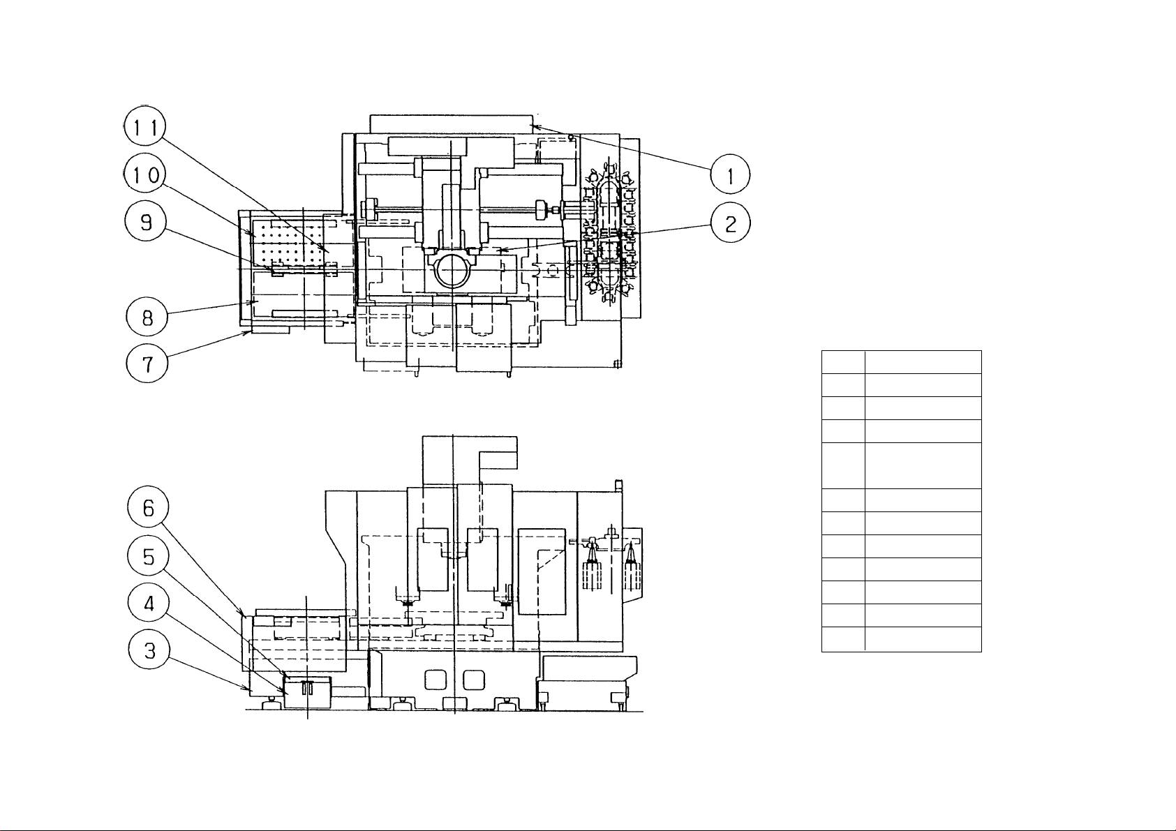
1 - 2
11 Automatic door
10 Left pallet
9 Pallet guide
8 Right pallet
APC individual
7
operation panel
6 Guard
5 Chip box
4 Coolant t ank
3 Base
2 Saddle
1 Air hydro-unit
No. Name
APC : Option
1-2-1 Whole Machine
1-2 Name of Each Section
Page 7
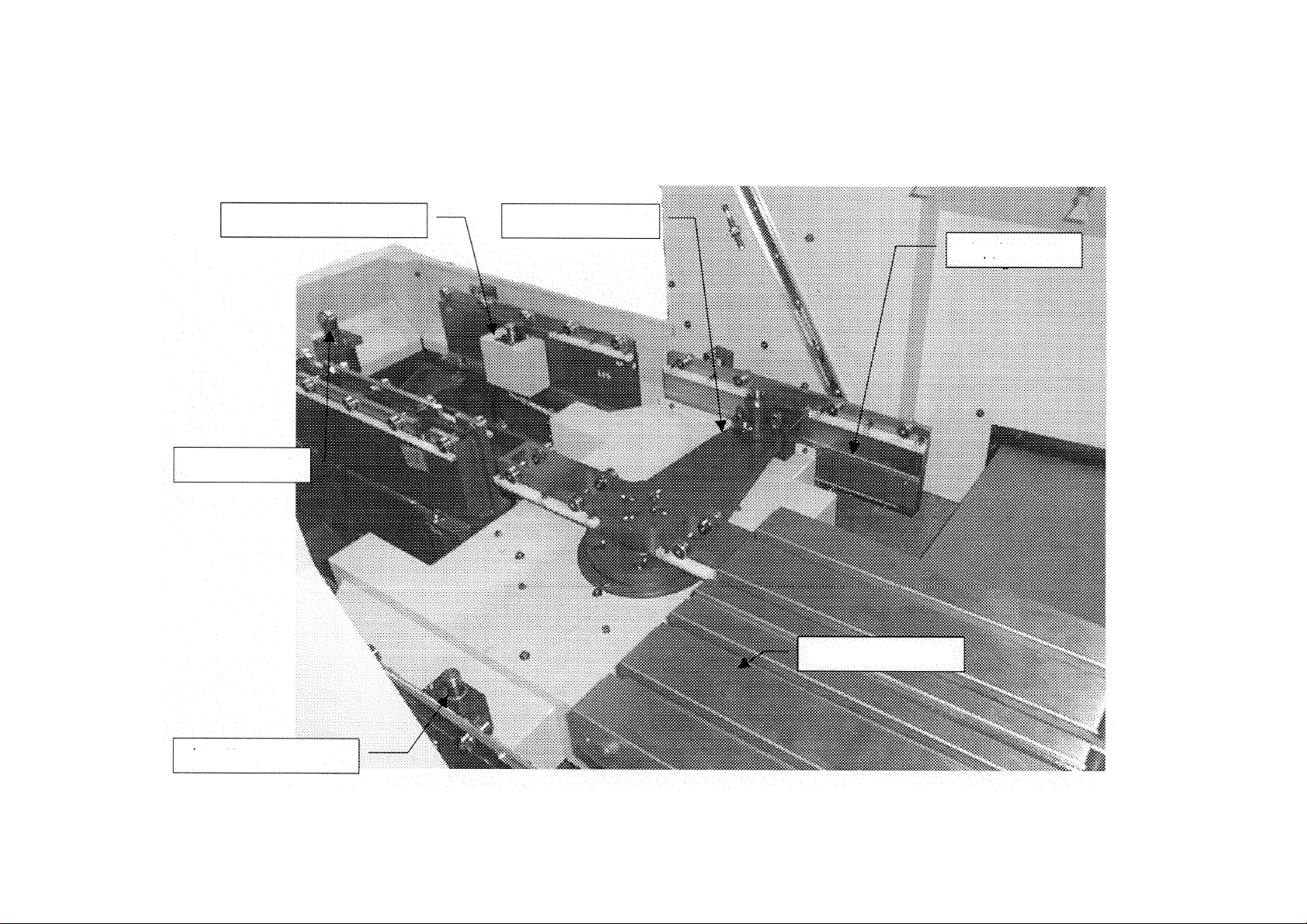
Name of Each Part of APC Unit
1-2-2
1 - 3
Rearranging stage
positioning pin
Temporary fixing
plunger
Rotary arm
Guide rail
Pallet (T-groove
specification)
Middle point positioning
pin
* The photograph is taken with the left pallet removed for convenience of explanation of
explanation.
Page 8
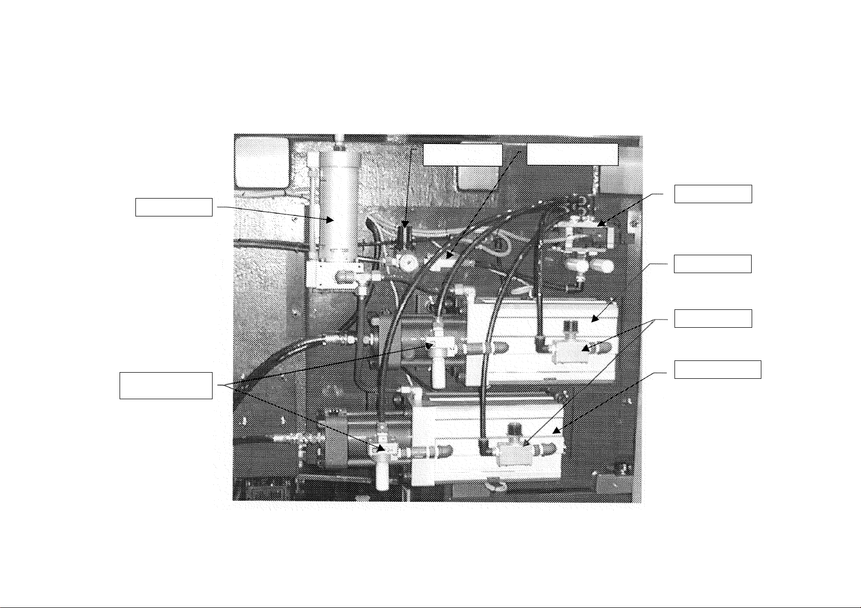
Name of Each Part of Air Hydro-unit
1-2-3
1 - 4
Reservoir tank
Rapid air release
valve
Regulator
Check valve
Solenoid valve
Clamp booster
Flow rate valve
Unclamp booster
* Photograph shows the air hydro-unit at the back of the machine proper . The cover is det ached
for convenience of explanation.
Page 9

2. SPECIFICATION
2-1 Table of the Specifications
VS40 VS50 VS60
Pallet size mm 800 × 400 1000 × 450 1200 × 560
Contour of pallet top(Type 1) M16 × P80 M16 × P80 M16 × P100
(Type 2) 18mm T-grove × 3 18mm T-grove × 4 18mm T-grove × 5
No. of pallet 2 2 2
Max. loading capacity of
pallet
Pallet clamping power kg 1850 3700 3700
Distance from spindle end to mm 80 ~ 530 100 ~ 550 (Type 1) 130 ~ 580
pallet top surface mm 60 ~ 510 80 ~ 530 (Type 2) 130 ~ 580
Changing system
Distance from floor level to mm 950 (Type 1) 1000 (Type 1) 1020 (Type 1)
pallet top surface mm 970 (Type 2) 1020 (Type 2) 1020 (Type 2)
Machine weight (gross) kg 8300 9200 12300
kg 250 400 750
Rotary arm type Rotary arm type Rotary arm type
parallel shuttle parallel shuttle parallel shuttle
2 - 1
Page 10
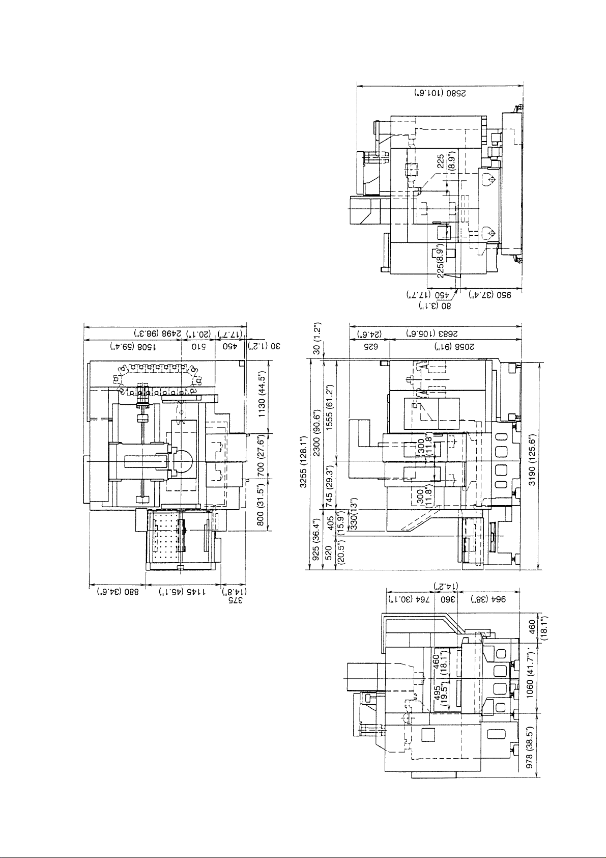
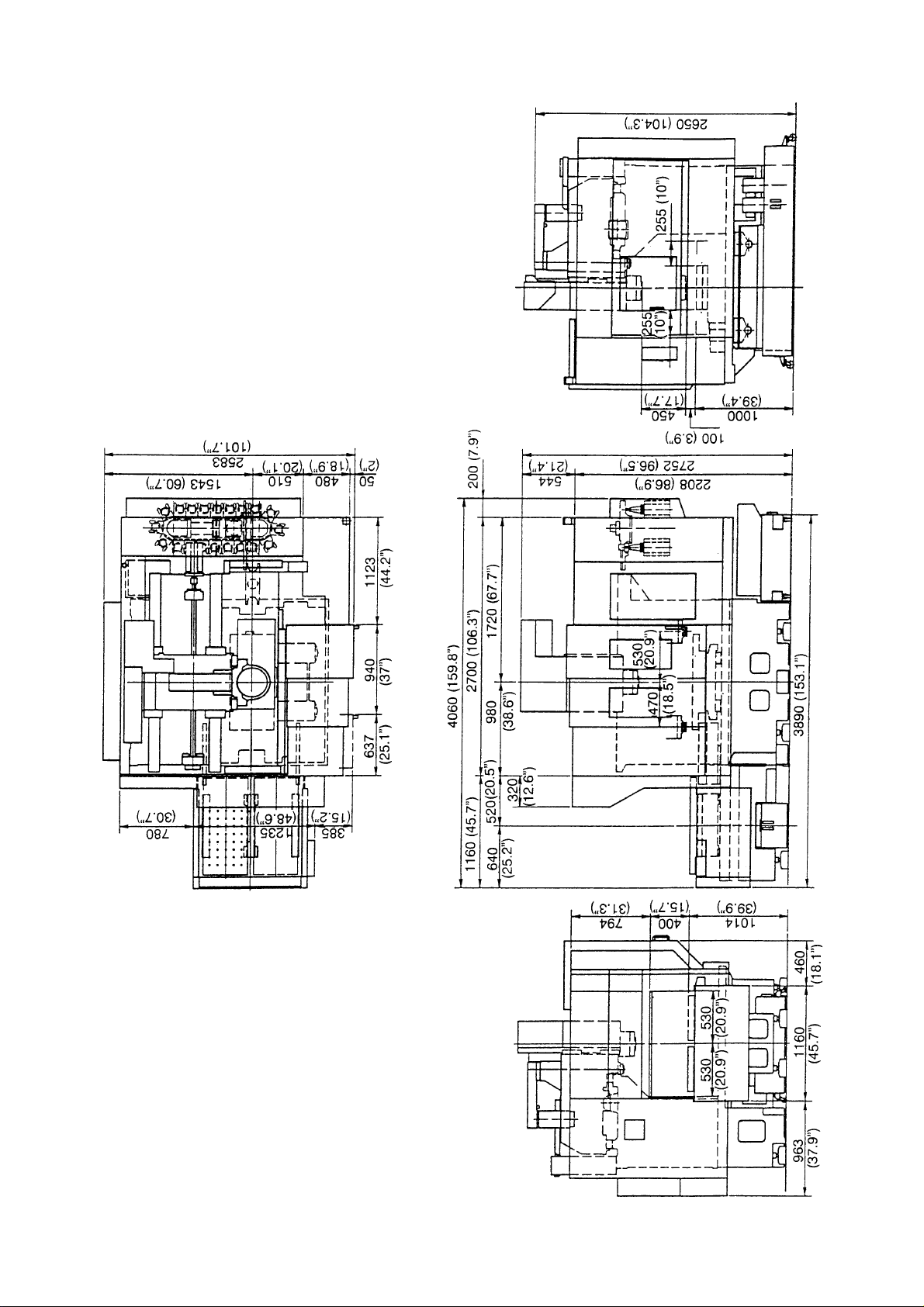
2-2 Main Dimension Diagram
VS40
Dimension : metric (mm)
Inch ( ” )
2 - 2
Page 11
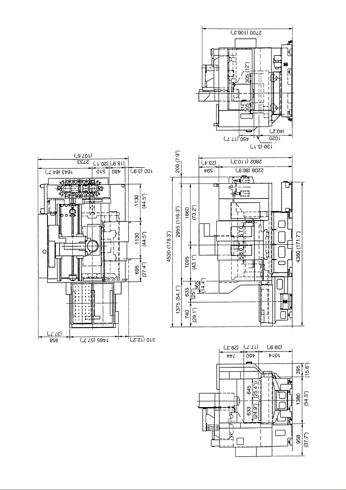
VS50
Dimension : metric (mm)
Inch ( ” )
2 - 3
Page 12
VS60
Dimension : metric (mm)
Inch ( ” )
2 - 4
Page 13
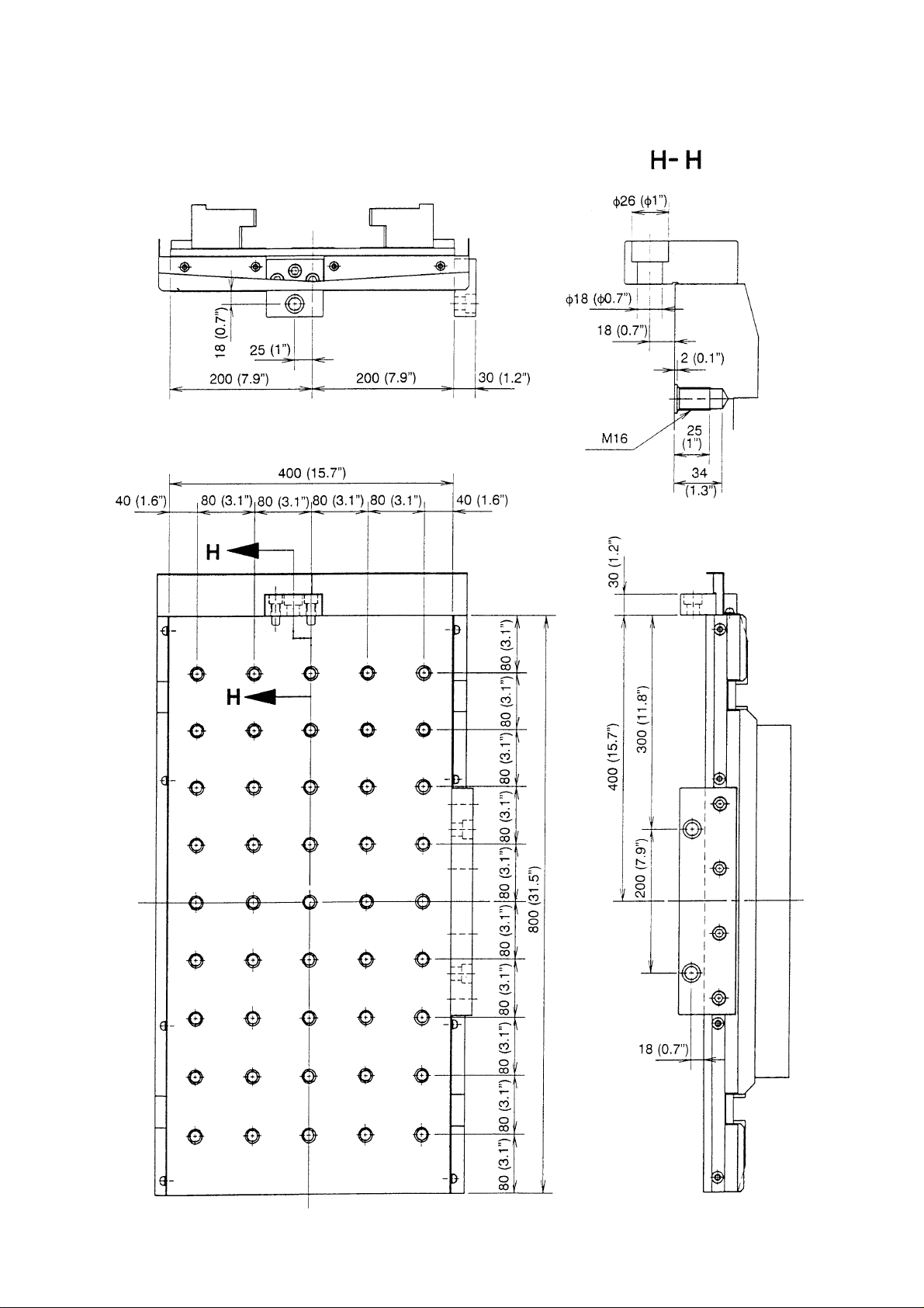
2-3 Pallet Dimension Diagram
VS40 Pallet Tapping Hole Specification
Dimension : metric (mm)
Inch ( ” )
2 - 5
Page 14

VS50 Pallet Tapping Hole Specification
Dimension : metric (mm)
Inch ( ” )
2 - 6
Page 15
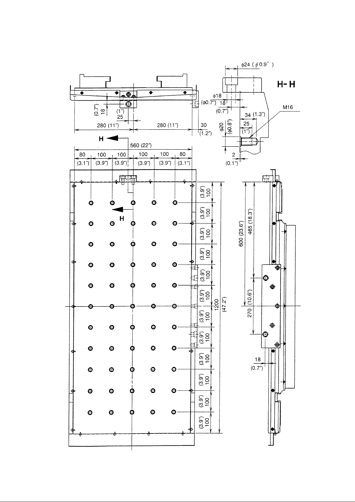
VS60 Pallet Tapping Hole Specification
Dimension : metric (mm)
Inch ( ” )
2 - 7
Page 16
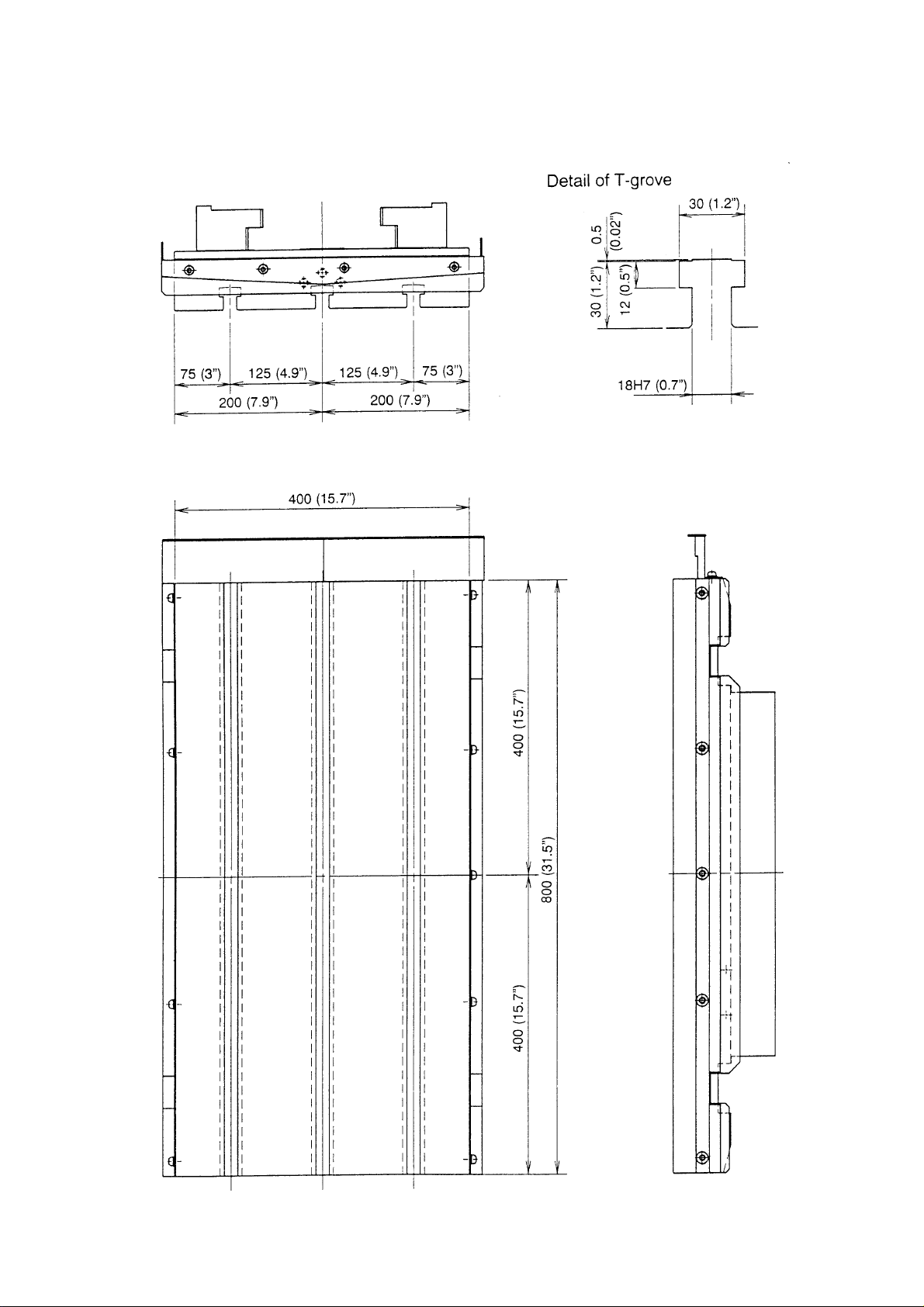
VS40 Pallet T-groove Specification
Dimension : metric (mm)
Inch ( ” )
2 - 8
Page 17
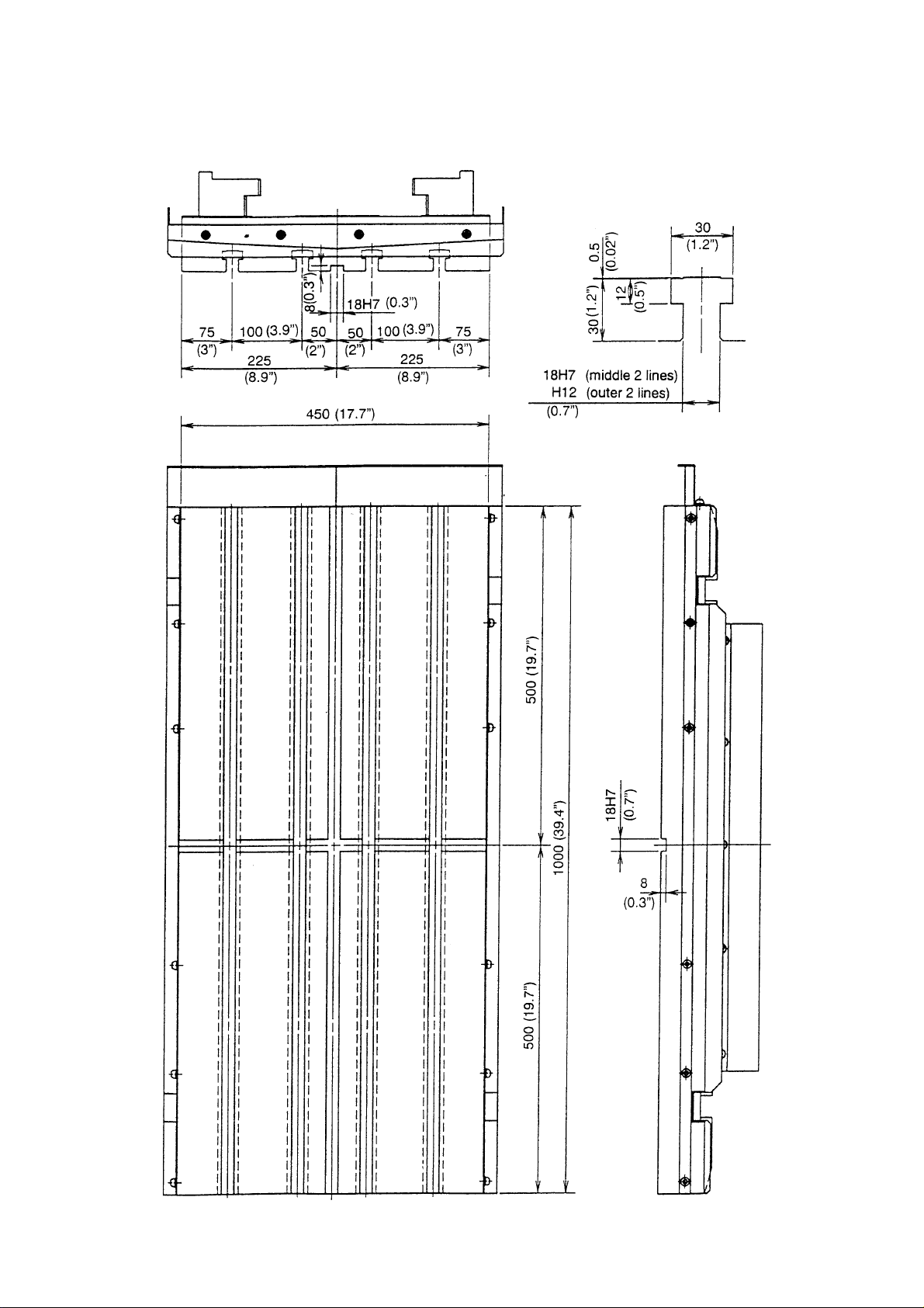
VS50 Pallet T-groove Specification
Detail of T-grove
Dimension : metric (mm)
Inch ( ” )
2 - 9
Page 18
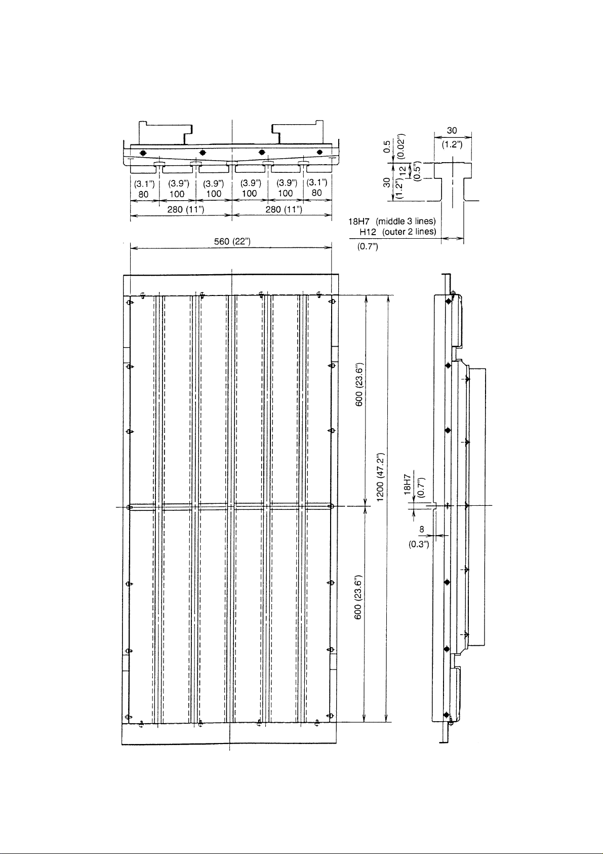
VS60 Pallet T-groove Specification
Dimension : metric (mm)
Inch ( ” )
Detail of T-grove
2 - 10
Page 19

2 - 11
Plane
Workpiece interference range diagram (VS40: 20/30 tool ATC)
2-4 Workpiece Interference Range
Note: Interference area
Range in which interference may occur depending on the height of work.
(Refer and confirm with the front and side view of interference range on the next
page.)
Dimension :metric (mm)
Inch ( ” )
Page 20

2 - 12
Dimension : metric (mm)
Upper stage: Bolt pallet
Lower stage: T-grove pallet
Inch ( ” )
Page 21

Dimension : metric (mm)
Inch ( ” )
2 - 13
Page 22

Workpiece interference range diagram (VS50)
Dimension :metric (mm)
Inch ( ” )
Note: Interference area
Range in which interference may occur depending on the height of work.
(Refer and confirm with the front and side view of interference range on the next
page.)
2 - 14
Page 23

2 - 15
Dimension : metric (mm)
Upper stage: Bolt pallet
Lower stage: T-grove pallet
Inch ( ” )
Page 24

Dimension : metric (mm)
Inch ( ” )
2 - 16
Page 25

Workpiece interference range diagram (VS60)
Dimension :metric (mm)
Inch ( ” )
Note: Interference area
Range in which interference may occur depending on the height of work.
(Refer and confirm with the front and side view of interference range on the next
page.)
2 - 17
Page 26

Dimension : metric (mm)
Inch ( ” )
2 - 18
Page 27

Dimension : metric (mm)
Inch ( ” )
2 - 19
Page 28

2 - 20
Page 29

3. OPERATION
3-1 Operation Procedure
Note: The action diagram shows the operation cycle of the left pallet shifting from the APC
rearranging stage into inside the machine and the right pallet out from inside the
machine to the APC rearranging stage. The operation of the right pallet → left pallet
→
progresses with the cycle [12]
[1] .
APC rearranging stage Inside machine
[1]
[2]
Rearranging
stage
stopper
Out
Return
Return
Return
Return
Center
stopper
Return
Out
Return
Out
Out
End position limit SW
No A B
692 ON OFF
693 OFF OFF
692 ON OFF
693 OFF OFF
692 ON OFF
[3]
[4]
3 - 1
Return
Return
Return
693 OFF OFF
Return
Out
692 ON OFF
693 OFF ON
Return
Page 30

APC rearranging stage Inside machine
[5]
Rearranging
stage
stopper
Return
Center
stopper
Return
End position limit SW
No A B
692 ON OFF
[6]
[7]
Return
Return
Return
Return
Return
Return
Out
Return
Out
Out
Return
Out
693 OFF ON
692 OFF ON
693 OFF ON
692 OFF ON
693 OFF ON
692 OFF ON
[8]
[9]
[10]
Return
Return
Return
Return
Return
Return
Return
Out
Return
Out
693 ON OFF
692 OFF ON
693 ON OFF
692 OFF OFF
693 ON OFF
3 - 2
Page 31

APC rearranging stage Inside machine
Rearranging
stage
stopper
Center
stopper
End position limit SW
No A B
[11]
[12]
Return
Return
Return
Out
Out
Return
Out
Return
692 OFF OFF
693 ON OFF
692 OFF OFF
693 ON OFF
3 - 3
Page 32

3-2 Individual Movement (At MDI or Maintenance Mode)
In case of execution of individual movement for test running or adjustment of maintenance
etc., operate a unit as follows.
1. Set a mode to the MDI.
2. Set the Y axis to the 3rd reference point by G91 G30 P3 Y0.
Or, set the Y axis to the 4th reference point by G91 G30 P4 Y0.
Confirm if the “APC POSITION” lamp on the main operation panel is lit at this time.
3. Turn on the maintenance mode switch in the control cabinet.
An alarm lamp goes on and off.
4. M codes to be used for individual movement are as follows.
5. Input M9 then start.
M code Motion
M906 Shutter open
M907 Shutter close
M903 Pallet unclamp
M902 Pallet clamp
6. Operate the right and left side pallet fix pin by the push button on the APC operation
panel.
Caution
Be specially careful not to perform any erroneous operation.
3 - 4
Page 33

3-3 Treatment at Power Failure or Emergency Stop
If power failure or emergency stop occurs during machine operation, a ready condition of
machine operation including the NC unit will be lost and also mostly memory and
movement command become clear condition. Therefore, after restoration from power
failure or emergency stop condition, the machine can not be operated without preparation
of ready condition of the NC unit and machine by fixed procedure.
About the restoration after emergency stop, carry out a restoration work after confirmation
of removing a cause of emergency stop.
When the ready button is pressed, pay attention to the part under operation immediately
before a power failure may be moved until remaining movement is completed according to
a condition of the hydraulic circuit.
[1] Visually check (position of axis is not checked) and ensure that Y-axis is located on the
pallet conveying position.
[2] Solve the cause of trouble such as the “half-way stop”.
[3] Reset the machine by performing each individual operation in the maintenance mode.
For the resetting method, refer to the above 3-2 Single individual operation.
Restoration after emergency stop during APC operation
[1] Press the operation preparation button to bring the system into status of operation
standby.
[2] Select the manual mode (feed, zero return) or the MDI mode.
[3] Confirm that the blinking light of the original position return button on the APC
operating panel is ON and press the button. Then the APC motion will start
automatically in the direction to allow restoration.
[4] On the way of restoration, when it comes to a status where the Y-axis is movable, the
APC movement stops.
[5] Select the MDI mode and, at the same time, confirm the contents of the alarm
message.
[6] According to the message, move the Y-axis to the third or fourth original point.
[7] Press again the original position restoration button on the APC operating panel. The
remaining action will start thereby the pallet is moved onto the table and the original
position is restored to complete the whole action.
3 - 5
Page 34

D413.3 APC limit switch is abnormal. (In case of requiring repairs of APC maintenance M910)
When APC relevant limit becomes abnormal, APC operation cannot be executed in the
normal way. If it is operated with a defective limit switch, there are risks of damaging the
machine. Be sure to replace the defective limit switch or make necessary repairs and
confirm the normal function of the switch before executing any restoration work.
X0004.0 LS693B LS at original position of right pallet.
X0003.7 LS693A LS at middle point of right pallet
X0008.0 LS692B LS at original position of left pallet
X0007.7 LS692A LS at middle point of left pallet
LS at pallet carrier arm original
X0008.1 LS39A
Confirm the ON/OFF condition of limit switch by diagnosis.
APC maintenance M910 (APC arm manual operation mode)
• Select the maintenance mode.
Put the maintenance switch on the control board ON, or execute M998.
• Execute M910.
APC door open and pallet unclamp are automatically executed and the system is brought
into the maintenance mode.
• The pallet fixing pin button on the APC operating panel changes to APC carrier arm inching
button.
Left pull out = Arm left turn
Right pull out = Arm right turn
• As the interlocking function is ignored for this arm inching operation, the movement of the
arm should be carefully watched visually. Any arm movement forcibly operated may cause to
machine damages.
position
(LS is OFF at original position)
3 - 6
Page 35

••
• There are two original positions of the APC arm.
••
When pallet is on the left side of
APC, the arm original position is
to the direction as shown by the
sketch on the left.
When pallet is on the right side of
APC, the arm original position is
to the direction as shown by the
sketch on the left
••
• Adjust the pallet position and the arm original position to coincide.
••
••
• Exit from the maintenance mode.
••
••
• Put the maintenance switch on the control board OFF, or execute M999 to exit from the
••
maintenance mode.
••
• By releasing the maintenance mode, the APC maintenance mode is also released.
••
3 - 7
Page 36

3-4 APC Program
Example 1) Without pallet check (M60)
Oxxxx
•
•
•
M60 ................. Use a macro program. Execute APC by calling O9001. (Carry
NOTE [1] If M60 is used at a machining program, carry in the outside pallet into the
machine without pallet check and enter a machining.
[2] Confirm the transfer preparation completion lamp of the APC operation panel
before execution of M60.
in the pallet at the outside into the machine.)
3 - 8
Page 37

Example 2) Program for pallet check (M157, M158)
Oxxxx
M36 ........................................ Automatic start OFF
N1 (R-PALLET IN)
M98 P93 (R-PALLET IN) O93 (R-PALLET IN SUB)
• G91 G28 Z0 M15
• M163
• G91 G30 P4 Y0
• M157 ........Pallet carry out
M98 ................. Machining G91 G30 P3 Y0
• program M158 ........Pallet carry in
• M99
•
M01
N2 (L-PALLET IN)
M98 P94 (L-PALLET IN) O94 (L-PALLET IN SUB)
• G91 G28 Z0 M15
• M163
• G91 G30 P3 Y0
M98 Pxxxx....... Machining M157 ........Pallet carry out
• program G91 G30 P4 Y0
• M158 ........Pallet carry in
• M99
•
M01
M35 ................. Automatic start ON
M30
When transfer preparation is ON, execute a heading
by M30 and start a machining again by carring out
the automatic start.
3 - 9
Page 38

3 - 10
Page 39

4. TRANSPORTA TION AND INST ALLATION OF THE MACHINE
4-1 Transportation of the Machine
As the construction of this machine is a type that the machine is integrated with the electric
appliances, the machine can be transported only by removing the power cord. As to the
fixing method of the moving sections and the lifting work, proceed as shown in Fig. 4-1.
4-1-1 Precautions for Lifting Work
Since the lifting work is one of the important set-up works when the machine is transported,
sufficient care should be taken. As the machine is transported through lifting works by
means of a crane or a chain block, the specific cautions for the lifting work are described in
the below.
(1) Use wire ropes with a diameter not less than 14mm (0.6”).
(2) Put pads on the sections with acute angle in order to protect the machine and the wire
rope.
(3) The machine is required to be lifted in a horizontal positions of the under surface of the
bed, and it is undesirable that the pallet changer side may become lower.
(4) Do not use rusted wires, untwisted wires or wires of which cor cable is broken.
(5) When lifting up the machine, wind up the wires gradually, and when the wire ropes are
tightened, stop lifting once to chick the lifting condition. Then, when the machine is
lifted up from the floor, check again if the lifting cable is normal, and then lift the
machine to the required height. When lowering the machine, the machine should be
lowered slowly. Then, lower the machine onto the floor.
4-1-2 Precautions for Lifting Work by a Forklift
(1) Select a forklift of which capacity is sufficient for the machine weight.
(2) When operating the forklift, be sure to work together with a supervisor for checking the
lifting work so that the projected sections of the machine periphery may not be
damaged.
(3) When driving the forks under the machine, use the cast grooves for inserting the forks
that are located at the left and right sides of the machine base.
(4) When lifting the machine, be sure to proceed provisional lifting work to check the
gravity of the machine both in the front and back direction and in the left and right
direction so that the machine may be lifted at the stablest position.
4 - 1
Page 40

Fig. 4-1 Figure of transportation (VS40)
4 - 2
Page 41

Figure of transportation (VS50)
4 - 3
Page 42

Figure of transportation (VS60)
4 - 4
Page 43

4-2 Environment for Machine Installation
Pay full attention to a room temperature, dust, vibrations, etc. in order to make use of the
primary performance of the machine. Needless to say that high accuracy cannot be
obtained in the environment where the room temperature greatly changes. Just a slight
change of the room temperature partly affects the machine. Be fully careful of effects heat
transfer from the direct sunshine, vent, heating unit, and so on.
Under the environment where the air is polluted so much by dust, etc., the sliding sections
and electric devices of the machine are greatly affected in their service lives.
Particularly, electronic devices related to controls are susceptible to dust and humidity.
Install the machine in the environment as clean as possible.
Also, the machine must be installed at a place free from vibrations caused by other
machines.
In case that electric machines and appliances generating high frequency noise are installed
near by NC machines, or newly erected keep to the following precautions.
1. Example of the electric machines and appliances generating high frequency noise.
(1) Arc welding machines
(2) Resistance welding machine
(3) High frequency drying machine
(4) Electric discharge machine
(5) Others
2. Installation norm of NC machines
(1) Power supply line
The power supply line (AC200V) of NC cabinet shall be separated line with that for
electric machines and appliances. If impossible, connect the line at the point more
than 20m apart from the point where the power supply for electric machines and
appliances is connected.
(2) Installation place of NC
NC shall be installed more than 20m apart from electric machines and appliances.
(3) Earth of NC
The earth of NC shall be grounded within 5m from the NC separating from the
ground of electric machines and appliances, and grounded at not more than
100Ω)
The thickness of earth wire shall be not less than 1.25mm
2
.
4 - 5
Page 44

3. Example of installation of NC Machine
The installation state of NC and electric machine and appliances are illustrated as under.
4-3 Construction of Foundation
To make the machine exibit its performance fully, construct the foundation for machine
installation with a bearing capacity of soil of 5 tons/m
and required floor dimensions, refer to Fig. 4-2.
2
or more. For the foundation drawing
4 - 6
Page 45

Fig. 4-2 Foundation layout diagram for the machine with APC (VS40)
Note 1) The resistivity of ground should be 5 ton/m
2
or more and the thickness of foundation,
300mm (11.8”) or more.
2) The range of foundation should be 300mm (11.8”) or more around the circumference
of bed.
3) When installing anti-vibration ditch, install along the circumference of foundation.
Dimension : metric (mm)
Inch ( ” )
4 - 7
Page 46

Foundation layout diagram for the machine with APC (VS50)
Note 1 ) The resistivity of ground should be 5 ton/m
2
or more and the thickness of foundation,
300mm (11.8”) or more.
2) The range of foundation should be 300mm (11.8”) or more around the circumference
of bed.
3) When installing anti-vibration ditch, install along the circumference of foundation.
Dimension : metric (mm)
Inch ( ” )
4 - 8
Page 47

Foundation layout diagram for the machine with APC (VS60)
Note 1) The resistivity of ground should be 5 ton/m
2
or more and the thickness of foundation,
300mm (11.8”) or more.
2) The range of foundation should be 300mm (11.8”) or more around the circumference
of bed.
3) When installing anti-vibration ditch, install along the circumference of foundation.
Dimension : metric (mm)
Inch ( ” )
4 - 9
Page 48

4-4 Installation of Machine
4-4-1 Preparation for Installation
(1) Preparation Items
Item VS50/60 VS40/50/60
Spindle specification 4500 10000 12000 High 20000
Primary power capacity 25 40 18 36 31
(KVA)
Main fuse (A) 100 150 100 125 125
Power line thickness 38 60 22 50 50
(Min. mm
Grounding wire resistance 8 8 8 8 8
100Ω or less (3rd Class)
(Min. mm2)
Cutting oil () 420
(Air supply)
Pressure (MPa {Kgf/cm2}) 0.5 (5)
Capacity (
Machine side piping RC1/4 or 3/8 ” hose
2
)
/min. ANR) 100
12000
power
Note 1) When installing a leakage circuit breaker with source power
Select the rated sensitivity of 200mA.
2) Grounding is to conform to the 3rd Class standard (100Ω or less).
Do not make wire connection with constructional iron frame.
a) Electric wiring
Wiring provided for this machine connects between the machine proper and its
attachments only. The user is kindly requested to prepare wiring from the supply
power source to the control cabinet. Although an electric wire used for this
purpose slightly differs depending on a distance from the power source to the
control cabinet, it is necessary to connect with the one whose sectional area is
22mm2 (0.87”) or more.
b) Pneumatic source
Since this machine requires supply of compressed clean air for blowing off chips
and cleaning the spindle hole and tool shank part also for pallet clamp/unclamp
pneumatics and other use, prepare air source of a proper capacity. (pressure:
0.5MPa {5kgf/cm2} or higher, flow rate:100/min; ANR, tank capacity of
compressed air source; 40
or larger)
4 - 10
Page 49

This pneumatic source must be naturally free from dust contained in the air and
oversaturated moisture. Due to a nature of the air, as the air temperature of the
pneumatic source increases higher than the temperature of the machine proper, it is
cooled on the machine proper side and causes water drops more easily. If moist air is
injected, it may rust the spindle hole and tool shank, thus having ill effects on
machining accuracy and a cutting surface. Therefore, the better, the lower the air
temperature of the pneumatic source is. When there is a great temperature
difference, attach an air dryer between the pneumatic source and the machine.
An air coupler 30SH + 2OPM (NITTO KOKI make) is attached to the machine.
Please prepare a 3/8” hose and hose band by yourself and connect it.
c) Oil supply
Usually there is no need of supplying oil, however, when it becomes necessary for
some reason, pay full attention to the following points.
1. Supply specified oil by specified amount. Do not supply a different type of oil or
over the specified amount. Otherwise, the machine may malfunction.
2. Clean an oil inlet port in advance lest dust, etc. should enter inside.
3. When supplying the oil, use a filter to prevent foreign substances from entering
inside the tank.
When the filter is not available, use a wire net of 150 mesh or more.
4. Whenever you supply the oil, use new one. Do not mix with reproduced or old
oil.
5. Even when opening a new oil can, do not use all oil in it, but leave some
unused. This is necessary to eliminate moisture and deposits.
4 - 11
Page 50

4 - 12
4-4-2
Caution at Time of Mounting Pallet
Mount a pallet at each work rearranging position in such a way that the phase of the location
confirming dog on the side of the pallet and the location confirming limit switch matches.
Note: APC does not work, when the pallet is mounted on the work rearranging position where the
phase of the dog and the limit switch mismatches.
Location confirming
dog
Pallet temporary fixing
plunger
Location confirming limit
switch
* The photograph is taken with the side cover of pallet removed for convenience of explanation.
Page 51

5. INSPECTION AND ADJUSTMENT
5-1 Daily Inspection
The following maintenance should be performed by the operator. The maintenance and
adjustment are important matters in order to prevent the machine from occurring failure,
and to operate the machine efficiently.
5-1-1 Checks Before Daily Operation
(1) Whether oil in the lubrication oil tank is sufficient.
(2) Clean every operation panel.
(3) Whether there is any leakage of oil or air.
(4) Cleaning of the spindle hole, tool magazine grip and ATC double arm part.
(5) Remove chips and swarfs on the covers for the slideways and the rollers for
transportating the pallets.
(6) Whether oil in the in the reservoir tank of the air hydro-unit part.
(7) Whether the cooling fan for the control cabinet is rotating.
(8) Whether there is any abnormal sound or vibration.
(9) Whether any alarm messages such as battery alarm etc. are displayed on the CRT.
5-1-2 Monthly Checks
(1) Power voltage check
Check whether secondary voltage of the main breaker is within ±10% of the specific
value. (200/220V 50/60Hz)
(2) Clean the cooling fans and fins on the inside and outside of the power control cabinet.
(3) Checking and cleaning of each part of the ATC arm.
(4) Checking of the condition of the pallet carrier and cleaning.
(5) Clean the inside of the coolant tank.
5-1-3 Checking Item Every 3 Months
(1) Check the machine and measure and compensate backlash of every screw section of
the machine.
(2) Measure and correct the level of the machine.
(3) Check the looseness of the movable sections and the clamping sections of the doors
and covers.
5 - 1
Page 52

5-2 Diagnosis No.
(1) In case of SEICOS Σ18M/Σ16M
OPER/MAINT → F4 system R 2. Diagnosis INPUT → 1 (In/Out signal) INPUT
1. In/Out signal → F6 X contact X can be seen.
F7 Y contact Y can be seen.
Items (Device) No.
Shutter open (MS-42) Y0009.3 (LS37A) X0009.4
Shutter close (MS-41) Y0009.2 (LS37B) X0009.5
APC arm carrier right turn (Inverter
motor normal revolution)
APC arm carrier left turn (Inverter
motor reverse revolution)
Right side pallet positioning pin in (LS42B) X0000.3
Right side pallet positioning pin pull out (SOL42A) Y0005.2 (LS42A) X0000.2
Left side pallet positioning pin in (LS41B) X0000.6
Left side pallet positioning pin pull out (SOL41A) Y0005.4 (LS41A) X0000.5
Pallet unclamp (SOL36B) Y0008.6 (LS36B) X0000.1
Pallet clamp (SOL36A) Y0008.5 (LS36A) X0000.0
Right pallet at the original position (LS693B) X0004.0
Left pallet at the original position (LS692B) X0008.0
Right pallet at mid-position (LS693A) X0003.7
Left pallet at mid-position (LS692A) X0007.7
APC arm at the original position (LS39A) X0008.1
Carriage standby complete (Lamp) Y0015.2 (Button) X0007.3
(R133) Y0013.3
(R134) Y0013.4
5 - 2
Page 53

5-3 Hydraulic · Pneumatic Circuit Diagram
5 - 3
Page 54

Parts List
No. Code Part of name Model Maker Type
1 04-999116702 Cylinder RSDQA50-20B-A73-XA6 SMC VS40/50/60
2 04-999116719 Solenoid valve VF1 130-1DZ-01 SMC VS40/50/60
3 Solenoid valve VT307-1DZ-02-F SMC VS40/50/60
4 04-999116726 Manifold VV5F1-30-021 SMC VS40/50/60
5 04-999118173 Silencer AN303-03 SMC VS40/50/60
6 04-190413110 Nylon tube TS0806B SMC VS40/50/60
7 04-999043930 Nylon tube TS1209B SMC VS40/50/60
8 04-999017719 Regulator AR2000-02BG SMC VS40/50/60
9 Check valve AK4000-02 SMC VS40/50/60
10 04-999046647 Silencer AN103-01 SMC VS40/50/60
1 1 Solenoid valve VFR4210-1DZ-03 SMC VS40/50/60
12 04-999080733 Quick exhaust valve AQ3000-03 SMC VS40/50/60
13 Flow meter AS5000-03 SMC VS40/50/60
14 04-999115736 Reservoir tank CCT63-100 SMC VS40/50/60
15 2782-00-406-00 Booster CDQ2L140-180-XB4-X SMC VS50/60
16 04-999050147 Hose assembly P105-9*240CM FU-FU Without WB SHONAN VS40/50
17 04-999105120 Hose assembly P105-9*214CM FU-FU Without WB SHONAN VS40/50
18 2781-00-402-00 Booster CDQ2LH140-P6024-9 SMC VS40
19 04-999123317 Hose assembly P105-9*260CM FU-FU Without WB SHONAN VS60
20 04-999034677 Hose assembly P105-9*254CM FU-FU Without WB SHONAN VS60
5 - 4
Page 55

5-4 Expendable Parts List
No. CODE NO. PRODUCT NAME MODEL VOLUME MAKER REMARKS
P ALETTE TABLE
1 02-999033894 Proximity switch E2E-X3D1-N-5M 2 Omron VS40/50/60
2 03-821120020 Roller follower NA2204LL 1 NTN VS40/50/60
3 03-913114200 Bush 70B-1420 2 Oiles VS40/50/60
4 03-999028169 Cam follower CF-SFU-10-1 8 IKO VS40/50
5 03-999028169 Cam follower CF-SFU-10-1 10 IKO VS60
6 04-190413110 Nylon tube TS0806B 4 SMC VS40/50/60
7 04-824440100 Packing SKY-80
8 04-851101410 Dust seal DKI142457 1 NOK VS40/50/60
9 04-999043930 Nylon tube TS1209B 2 SMC VS40/50/60
10 04-999050147 Hose assembly
1 1 04-999105120 Hose assembly
12 04-999117882 Packing SPG 110
13 04-999117899 O-ring GS155 (Circle 3.1) NBR
14 2782-00-406-00 Booster CDQ2L140-180-XB4-X 2 SMC VS50/60
15 2782-00-407-00
16 2782-00-538-01 Telesco cover
Air equipment VS50 Air equipment complete
complete set set for palette table
P105-9*240CM FU-FU
Without WB
P105-9*214CM FU-FU
Without WB
VS50 APC for Y-axis
580 stroke
4
2 VS40
1 Shonan VS40/50
1 Shonan VS40/50
2
1 VS40
4
3 VS40
1 SMC VS40/50/60
1 Enomoto VS50
Sakagami
NOK
Shoritsu
VS50/60
VS50/60
VS50/60
17 2782-00-539-00 Slide cover VS50 APC for Y-axis 1 Enomoto VS50
18 2782-10-439-01 Spring/C coil SWPA 1 VS40/50/60
19 2782-10-441-10 Shoe 2 VS40/50/60
20 04-999034677 Hose assembly
21 04-999123317 Hose assembly
22 2783-00-505-00 Telesco cover
23 2783-00-506-00 Thread cover VS60 APC for Y-axis 1 Enomoto VS60
24 2781-00-522-00 Telesco cover
25 2781-00-523-01 Slide cover VS40 APC for Y-axis 1 Bellows VS40
P105-9*260CM FU-FU
Without WB
P105-9*254CM FU-FU
Without WB
VS60 APC for Y-axis
680 stroke
VS40 APC for Y-axis
450 stroke
1 Shonan VS60
1 Shonan VS60
1 Enomoto VS60
1 Bellows VS40
5 - 5
Page 56

APC
No. CODE NO. PRODUCT NAME MODEL VOLUME MAKER REMARKS
1 02-341200610 Limit switch 1LS1-J 4 Yamatake VS40/50/60
2 02-999033894 Proximity switch E2E-X3D1-N-5M 1 Omron VS40/50/60
3 03-662094000 Angular ball bearing 6209ZZ 2 VS40/50/60
4 03-662160000 Angular ball bearing 6216 2 VS40/50/60
5 03-821120020 Roller follower NA2204LL 2 NTN VS40/50/60
6 03-913120200 Bush 70B-2020 4 Oiles VS40/50/60
7 03-999009449 Cam follower CF12UU With nut
8 04-999055249 Seal ring
9 04-999116702 Cylinder RSDQA50-20B-A73-XA6 2 SMC VS40/50/60
10 04-999116719 Solenoid valve VF1130-1DZ-01 2 SMC VS40/50/60
1 1 04-999118647 Oil seal SC9512013 AC3994E0 1 NOK VS40/50/60
12 2782-10-439-01 Spring/C coil SWPA 2 VS40/50/60
13 2782-80-441-10 Shoe 10 VS50/60
14 2781-80-435-01 Shoe 10 VS40
15 03-999028169 Cam follower CF-SFU-10-1 8 IKO VS40
APC COVER
1 02-341201450 Proximity switch SL1-A 2 Y amat ake VS40/50/60
2 2782-00-546-00 Roller chain
3 2783-00-507-00 Roller chain
OV-195*205*5
Joint type seal
RS35.K1 Attachment 75
links Special hole chain
RS35.K1 Attachment 81
links Special hole chain
37
29 VS40
1
1
1
THK
Nihon uni
Tsubakimoto
Tsubakimoto
VS50/60
VS40/50/60
VS50
VS60
4 2782-75-356-10 Wiper WP-34 1 VS40/50
5 2782-75-369-00 Wiper WP-34 1 VS50
6 2782-75-470-00 Wiper HSW-1 1 VS50
7 2782-75-471-00 Wiper HSW-1 1 VS50
8 2782-75-472-00 Wiper HSW-1 1 VS50
9 2782-75-473-00 Wiper HSW-1 1 VS50
10 2783-75-339-00 Wiper WP-34 1 VS60
11 2783-75-340-00 Wiper WP-34 1 VS60
12 2783-75-440-00 Wiper HSW-1 1 VS60
13 2783-75-441-00 Wiper HSW-1 1 VS60
14 2783-75-442-00 Wiper HSW-1 1 VS60
5 - 6
Page 57

No. CODE NO. PRODUCT NAME MODEL VOLUME MAKER REMARKS
15 2783-75-443-00 Wiper HSW-1 1 VS60
16 2782-00-575-00 Roller chain
17 2782-75-372-00 Wiper WP-34 1 VS50
18 2782-75-373-00 Wiper WP-34 1 VS50
19 2781-00-525-00 Roller chain
20 2781-75-350-00 Wiper WP-34 1 VS40
21 2781-75-452-00 Wiper HSW-1 1 VS40
22 253-00 Wiper HSW-1 1 VS40
23 2781-75-454-00 Wiper HSW-1 1 VS40
24 2781-75-455-00 Wiper HSW-1 1 VS40
RS35.K1 Attachment 95
links Special hole chain
RS35 K1 Attachment 69
links Special hole chain
1
1
Tsubakimoto
Tsubakimoto
VS50
VS40
5 - 7
Page 58

MACHINING CENTER
VS40/50/60
APC
INSTRUCTION MANUAL
SEIKI-SEICOS Σ16M/18M
Version 1.01
3-2001
First Edition 9-2000
1
 Loading...