

Page 1
PROGRAMMING
FOR
MANUAL
VM,
SEIKI-SEICOS
VK,
VS,
MACHINING
Edition
HG,
21
1
10-1998
HS
CENTER
OM/1
6M/1
TYPE
8M
S
PSEiKl
Hitachi
S
Page 2

f
1
a
Page 3
TABLE
CONTENTS
OF
INTRODUCTION
1.
FLOW
1-1
Programming
1-2
PROGRAMMING
2.
Program
2-1
PROGRAM
2-2
Main
2-3
Subprogram
2-4
Composition
2-5
2-6
Address
Data
2-7
2-8
Word
Block
2-9
2-10
1
2-1
2-12
2-13
2-14
2-15
2-16
Absolute
2-17
Incremental
2-18
Right
2-19
Z-axis
2-20
X-axis
2-21
Y-axis
2-22
2-23
Z-axis
X,
2-24
CHART
No
program
Sequence
How
Tape
Tape
Tape
Address
Program
prepare
to
dimension
code
format
hand
zero
standard
Y,
Z
MACHINING
FOR
type
LANGUAGE
program
of
No
sequence
specification
meaning
and
and
point
zero
command
(absolute
command
perpendicularly
point
coordinate
.
.
No
coordinate
coordinate
(incremental
crossing
actual
and
WORK
system
value)
coordinate
work
MACHINING
BY
value)
system.
CENTER
1-1
1-2
1-3
2-1
2-1
2-1
2-2
2-2
2-2
2-5
2-6
2-6
2-6
2-7
2-7
2-8
2-8
2-9
2-10
2-11
2-12
2-13
2-14
2-14
2-14
2-15
2-15
2-16
M,
S,
3.
Miscellaneous
3-1
Command
3-2
Command
3-3
T,
FUNCTIONS
F,
B
method
method
(M-function)
pallet
of
spindle
of
change
speed
(For
(S-function)
with
VK
I
APC)
3-1
3-1
3-2
3-5
Page 4
3-4
Tool
Programming
3-5
Programming
3-6
No.
call
(T-function)
example
example
of
of
tool
tool
change
change
of
(Case
(CaseofHG)
VM,
VK,
VS)
3-6
3-8
3-9
Command
3-7
Table-indexing
3-8
G-FUNCTION
4.
AAA
G
4-1
GOO
4-2
4-3
4-4
4-5
4-6
4-7
4-8
4-9
4-10
4-11
4-12
4-13
4-14
4-15
4-16
(Positioning)
(Linear
G01
G02,
G02,
G02,
G02,
Summary
(dwell)
G04
Exact
G17,
G27
G28
G29
G30
G31
method
(preparatory
interpolation)
(circular
G03
G03
(program
(program
G03
(program
G03
GOO,
on
(G09)
stop
G19
G18,
(zero-point
(auto-zero
(auto-return
(2nd,
3rd,
function)
(skip
of
feed
command
interpolation)
example)
example)
example)
G01,
(plane
return
return)
4th
indication)
check)
zero
from
reference
.....
speed
method
function)
G02,
(F-function)
(B-function)
G03
.
point)
return)
point
. .
3-12
HG
series
3-13
4-1
4-1
4-2
4-3
4-4
4-5
4-6
4-7
4-8
4-9
.
4-10
4-11
4-12
4-13
4-14
4-15
4-16
5.
G-FUNCTION
Philosophy
5-1
length
Tool
5-2
5-3
Tool
diameter
Tool
5-4
5-5
5-6
5-7
5-8
5-9
5-10
diameter
Summary
G41,G42
G42
G41,
(cancel)
G40
Example
Example
(length
compensation,
compensation,
length
tool
of
compensation
compensation
compensation
tool
tool
tool
diameter
mode)
diameter
diameter
of
(start-up)
(offset
of
of
diameter
position
compensation
(G43,
compensation
compensation
compensation
compensation)
G44,
G41,
G42,
G41,
G42,
II
(G43,
G49)
G40
G40
program
program
G44,
.
G49)
5-1
5-1
5-2
5-5
5-6
5-7
5-8
5-10
5-12
5-15
5-16
Page 5
5-1
1
Example
of
tool
diameter
compensation
program
5-17
5-12
Example
3
Example
5-1
5-14
Example
5-15
Tool
Offset
corner
Tool
5-16
Tool
5-17
Example
8
5-1
Example
5-1
9
G-FUNCTION
6.
6-1
Setting
Caution
6-2
6-3
Work-coordinate
Work-coordinate
6-4
Example
6-5
Additionofwork
6-6
6-7
Selection
6-8
Local
G52
Data
One
program
6-9
6-10
6-11
tool
of
of
of
diameter
vector
circular
diameter
diameter
tool
tool
diameter
compensation
change
arc
compensation
position
of
offset
using
using
(coordinate
coordinate
use
the
for
using
work-coordinate
the
the
system
system
coordinate
machine-coordinate
of
coordinate
setting
directional
system
example
(G10)
positioning
compensation
compensation
compensation
Tool
and
(G39)
tool
number
G46,
by
(G45,
positional
tool-position
system)
system
(G54
of
(G92)
~
(G54
G54,
system
(G52)
.(G60)
vector
radius
G47,
offset
offset
G59)
G59)
~
G55
system
system
program
program
program
(G38),
keep
compensation
G48)
tool
for
and
and
pair
radius
milling
for
G92
coordinate
number
(G53)
..
machining
work-coordinate
system
setting
.
(G540
~
G599)
G92
5-18
5-19
5-20
5-21
5-24
5-27
5-29
5-30
6-1
6-1
6-2
6-3
6-4
6-5
6-6
6-10
6-11
6-12
6-13
6-16
'
G-FUNCTION
7.
Canned
7-1
Ganned
7-2
7-3
Canned
7-4
Canned
7-5
Canned
Canned
7-6
7-7
Canned
Canned
7-8
Example
7-9
Herical
7-10
(canned
cycle
cycle
cycle
cycle
cycle
cycle
cycle
cycle
canned
of
cutting
(G73
(data
(G73,
(G76,
(G82,
(G84,
(G87,
G02,
cycle)
~
type,
G74)
G80,
G83)
G85,
G88,
cycle
G03
G89)
return
G81)
G86)
G89)
program
level)
7-1
7-1
7-2
7-3
7-4
7-7
7-8
7-11
7-12
7-13
7-14
III
f
Page 6
Programmable
7-11
Setting
7-12
3
Direct
7-1
Boring
7-14
Bolt-hole
7-15
Arc
7-16
Line
7-17
7-18
Grid
True
7-19
Square
7-20
Coordinate
7-21
Surface
7-22
Pocket
7-23
Multibuffer
7-24
Precedent
7-25
tapping
pattern
cycle
angle
at
cycle
circle
cutting
mirror
cycle
(G71)
(G77)
cutting
side
rotation
cutting
control
mirror
image
cycle
image
.
(G70,
(G70)
(G72)
cycle
(G302
outer
frame
(G68,
(G324,
cycle
(G327-G333)
.
G511,
G71,
G305)
~
cutting
G69)
G325,
G501
G72,
(G322,
G326)
G77)
G323)
....
..
7-15
7-17
7-19
7-25
7-26
7-27
7-28
7-29
7-30
7-42
7-45
7-49
7-61
7-86
7-88
*
OTHER
8.
Optional
8-1
Arbitrary
8-2
PRACTICAL
9.
Machining
9-1
9-2
Selection
Setting
9-3
Mounting
9-4
Relation
9-5
9-6095
9-7
9-8
9-9
9-10
9-1
9-12
30
0
018
08.5
M10
Borning
1
0
Program
FUNCTION
skip
block
angle
chambering
EXAMPLE
diagram
machining
of
of
selected
method
work-coordinate
with
Face
cutter
Boring
Center
Drill
Tapping
finishing
spindles
of
2
OF
plate
position
cutting
comer
and
PROGRAM
FC30
condition
system
(R,
tool-cutter
of
C,
R)
8-1
8-1
8-2
9-1
9-1
9-2
9-2
9-3
9-3
9-4
9-5
9-6
9-7
9-8
9-9
9-10
IV
Page 7
ATTACHED
10.
List
10-1
List
10-2
10-3
Related
G
function
of
for
function
M
itemstothe
LIST
(preparatory
(miscellaneous
tool-set
function)
functions)
(VM,
VK,
VS,
HG,
HS)
10-1
10-1
10-5
10-15
10-4
10-5
1
0-6
10-7
10-8
10-9
Howto
List
List
MC
TOOLING
If
obtain
standard
for
tape
for
MACHINE
LIST
AlarmisIssued
the
code
DATA
cutting
cutting
condition
conditions
10-16
10-17
10-18
10-21
10-22
10-23
v
Page 8

!
!
!
Page 9
INTRODUCTION
1.
Thank
This
In
the
you
manual
order
features
to
Explanation
methods.
and
the
Some
programs
format
the
given
Accordingly,
For
nance)".
This
optional.
difference
of
are
(FANUC
specifications
the
at
detail
manual
between
your
for
selection
describes
machining
this
use
functions
and
made
is
programming
described
specifications).
of
the
of
end
programming
make
of
parameter,
describes
Refer
"Delivery
to
the
the
of
necessary
for
terms,
separately
the
machine
this
etc.,
the
standard
introduction
and
programming
center
machine.
items
the
programming
according
Be
sure
used
manual.
upon
refer
to
programming
Description"
and
the
of
our
of
Machining
effectively,
on
it
programming,
methods,
S-format
to
understand
to
programming.
for
full
understanding
"SEIKI-SEICOS
regardless
provided
optional.
Machining
Center
necessary
is
such
fully
List
of
the
210M
type
the
the
at
Center.
with
understand
to
as
which
etc.
(SEICOS
descriptions
these
S-format
of
contents.
Instruction
the
of
time
of
SEIKI-SEICOS
and
programming
the
necessary
are
specifications)
according
and
F-format
Manual
machine,
delivery
standard
regarding
210M.
program
words
the
for
F-
and
to
is
(Mainte¬
or
the
1-1
Page 10
1-1
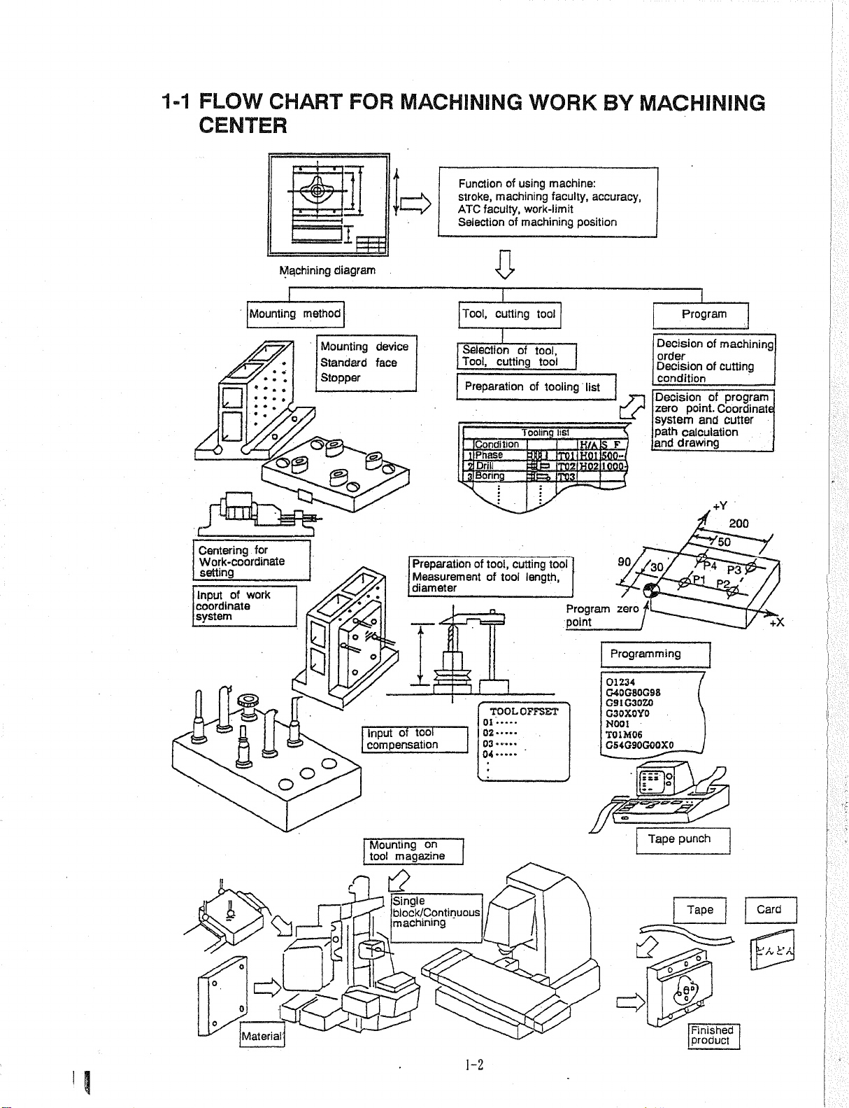
FLOW
CENTER
CHART
m
FOR
II
MACHINING
of
machining
faculty,
of
c>
Function
stroke,
ATC
Selection
WORK
using
machine:
faculty,
work-limit
machining
BY
accuracy,
position
MACHINING
Mounting
4Z
•
*
4
c
Centering
Work-coordinate
setting
Input
coordinate
system
for
_
work
of
Machining
method
O.
q.
PS
diagram
Mounting
Standard
Stopper
device
face
Tool,
Selection
Tool,
Preparation
Condition
I
Phase
1
1
Drill
Boring
3|
Preparation
Measurement
diameter
of
£
cutting
cutting
tool,
of
tool
tool
of
tool,
of
Tooling
m
cutting
length,
tool
tooling
list
T01
T02
T03
tool
list
H/A
HOI
H02
Program
point
c?
S
F
IOOO'
9°//30.
zero
Programming
Program
Decision
order
Decision
condition
Decision
zero
point.
system
path
calculation
drawing
and
of
machining
of
cutting
_
program
of
Coordinate
and
cutter
+Y
200
'50
3ÿP2_/
'
/
+X
rp
Mn
i
o
o
0
Material
o
o
o
7?
Input
compensation
Mounting
tool
£
CL
II
tool
of
on
magazine
_
Single
block/Continuous
machining
1-2
TOOL
01
02
03
—
04
OFFSET
01234
G40G80G98
G9IG30ZO
G30X0Y0
N00I
T01M06
GS4G90GO0X0
fnrio
Tape
[Zÿ>
\
punch
Tape
o
0
<32
Finished
product
Card
t'A,
fc'A
'I
Page 11
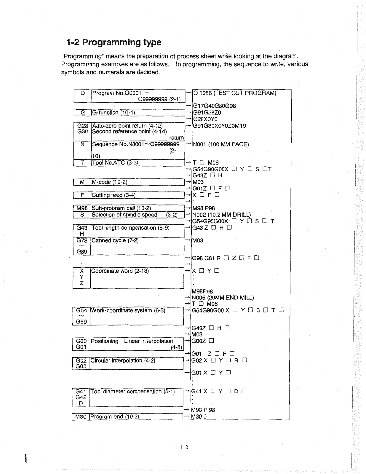
Programming
1-2
type
"Programming"
Programming
symbols
O
|
G
G28
G30
N
examples
numerals
and
Program
iG-function
Auto-zero
Second
Sequence
101
Tool
T
|
|
jM-code
M
Cutting
|
F
M98
jSub-probram
Selection
S
Tool
G43
H
G73
Canned
means
No.00001
preparation
the
as
are
are
decided.
~
099999999
(10-Tf
point
return
reference
No.N0001~099999999
No.ATC
(10-2)
feed
of
length
cycle
point
(3-3)
(3-4)
(10-2)
call
spindle
compensation
speed
(7-2)
follows.
(4-12)
(4-14)
(5-9)
process
of
In
programming,
(2-1)
return
(2-
-»
(3-2)
-»
while
sheet
the
(TEST
1986
O
G17G40G80G98
G91G28Z0
G28X0Y0
G30X0Y0Z0M
G91
(100
N001
M06
T
G54G90G00X
G43Z
M03
G01Z
F
X
P98
M98
(10.2
N002
G54G90G00X
G43Z
M03
H
F
H
MM
MM
CUT
FACE)
looking
at
sequence
PROGRAM)
9
1
S
Y
DRILL)
Y
S
the
to
DT
write,
T
diagram.
various
|
G03
G41
G42
M30
G89
Coordinate
X
Y
Z
I
Work-coordinate
G54
G59
Positioning
GOO
G01
Circular
G02
__
[Tool
D
iProgram
word
interpolation
diameter
end
(2-13)
system
Linear
compensation
(10-2)
terpolation
in
(4-2)
(6-3)
(4-8)
(5-1)
G98
G81
X
M98P98
N005
T
G54G90GOO
G43Z
M03
G00Z
G01
G02X
G01
X
-*
G41
X
!
P
M98
M30
0
R
Y
(20MM
M06
H
Z
Y
Y
Y
98
END
X
F
Z
R
D
F
MILL)
Y
T
S
l-3
I
Page 12

.
Page 13
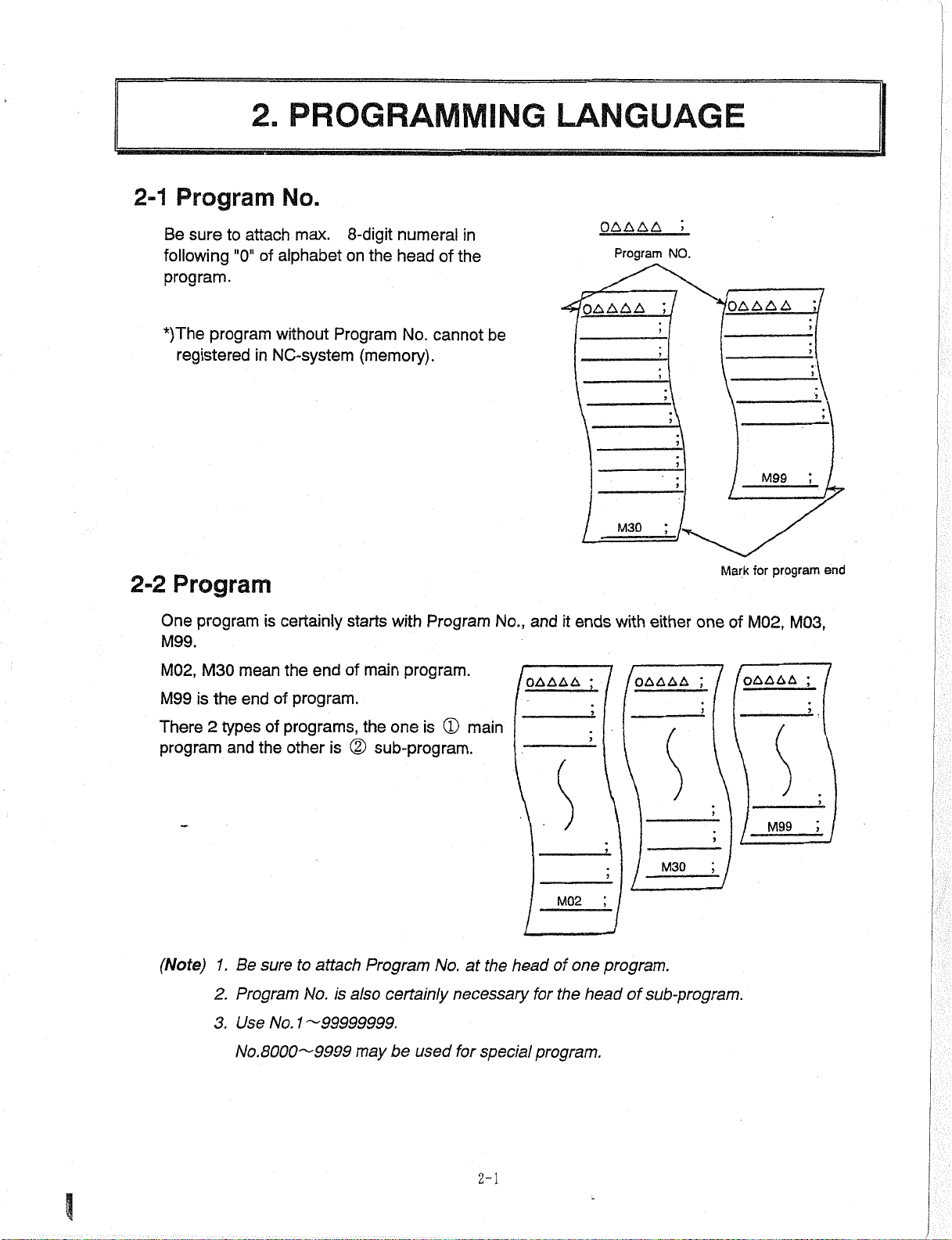
2-1
Be
following
program.
2.
Program
sure
to
"0"
attach
PROGRAMMING
No.
max.
alphabet
of
8-digit
on
the
numeral
head
of
in
the
LANGUAGE
OAAAA
Program
NO.
*)The
2-2
One
M99.
M02,
M99
There
program
program
registered
Program
program
M30
mean
end
is
the
2
types
and
without
NC-system
in
is
certainly
the
program.
of
programs,
of
the
other
Program
of
end
is
No.
(memory).
starts
with
program.
main
the
one
(2)
sub-program.
cannot
Program
(D
is
main
be
No.,
and
OAAAA
'OAAAA
it
ends
M30
d
either
with
/oAAAA
one
;
f
'OAAAA
M99
tor
Mark
M02,
of
OAAAA
I
i
program
M03,
;
end
M99
M30
y
(Note)
Be
1.
Program
2.
3.
Use
No.
attach
to
sure
No.
1ÿ99999999.
No.
8000ÿ9999
is
also
may
Program
certainly
be
used
No.atthe
necessary
for
special
2-1
head
for
program.
M02
of
the
i
one
head
I
program.
sub-program.
of
I
Page 14
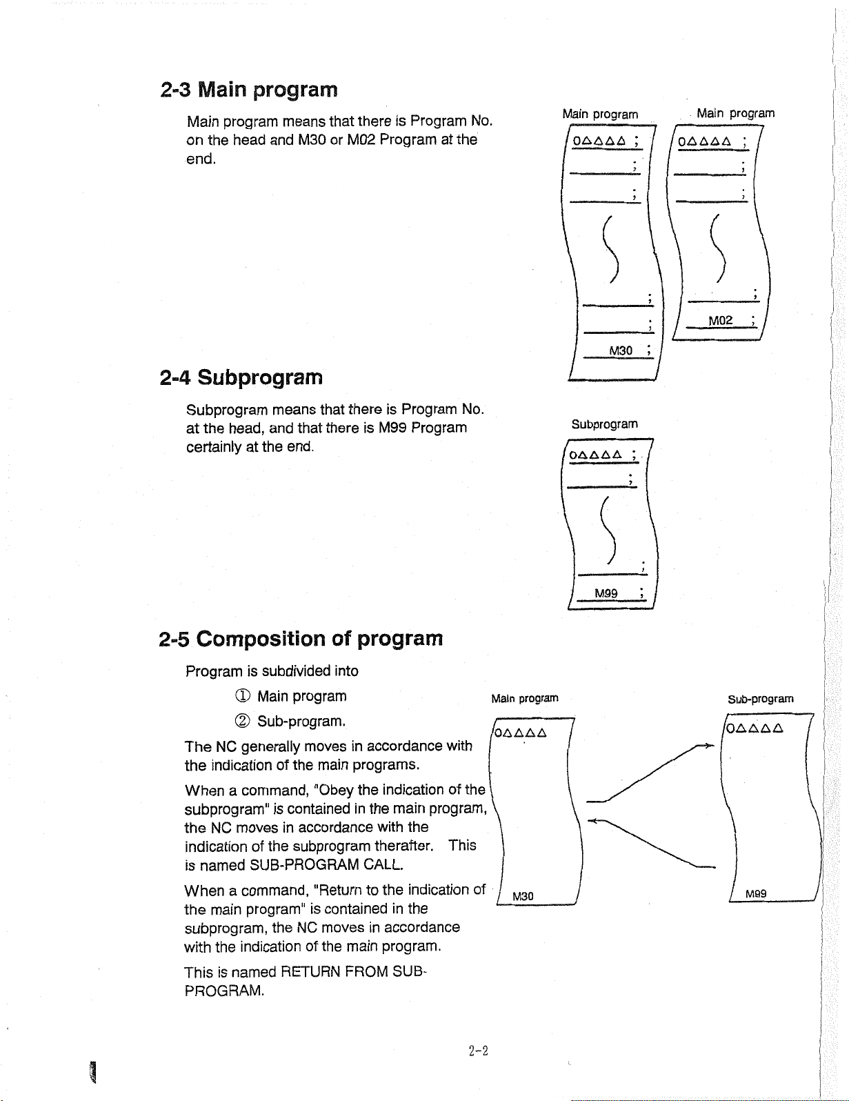
Main
2-3
program
Main
the
on
end.
Subprogram
2-4
program
means
and
head
M30
that
or
there
M02
is
Program
Program
at
the
No.
Main
OAAAA
program
M30
;
/
OAAAA
/
Main
M02
program
/
;
J
Subprogram
head,
the
at
certainly
Composition
2-5
Program
NC
The
indication
the
When
subprogram"
the
a
NC
indication
named
is
means
and
the
at
subdivided
is
(D
Main
(D
Sub-program.
generally
of
command,
is
moves
the
of
that
that
there
end.
program
moves
main
the
"Obey
contained
accordance
in
subprogram
SUB-PROGRAM
there
is
program
of
into
accordance
in
programs.
the
the
in
with
therafter.
CALL.
Program
is
M99
Program
indication
main
the
No.
with
the
of
program,
This
program
Main
/OAAAA
Subprogram
OAAAA
M99
;
kJ
Sub-program
/OAAAA
command,
When
the
subprogram,
with
This
PROGRAM.
a
main
the
named
is
program"
indication
"Return
is
NC
the
of
RETURN
to
contained
moves
the
in
main
FROM
the
indication
the
in
accordance
program.
SUB¬
of
2-2
M30
M99
Page 15
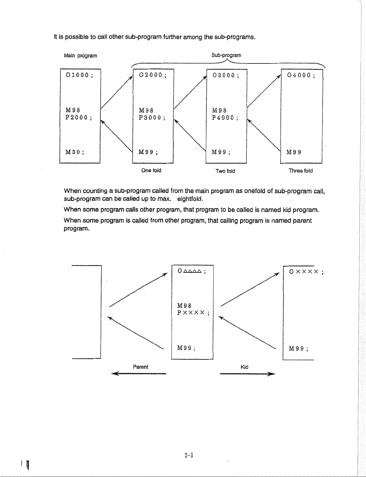
is
It
possible
to
call
other
sub-program
further
among
sub-programs.
the
program
Main
01000
M
P2000
3
M
When
;
9
8
;
;
0
countingasub-program
sub-program
When
When
some
some
program.
be
can
program
program
called
calls
is
called
02000
M98
P3000
M
9
9
One
to
up
other
from
;
;
;
fold
called
max.
program,
other
from
the
eightfold.
that
program,
Sub-program
03000
M
P4000
M
program
main
program
that
8
9
9
9
Two
to
calling
;
fold
be
;
;
as
onefold
called
program
is
named
04000
M
of
sub-program
kid
is
named
9 9
Three
fold
program.
parent
;
call,
<-
Parent
OAMA
M98
PXXXX
M99
;
;
;
Kid
M
XXX
x
0
9
9
;
;
H
2-3
Page 16
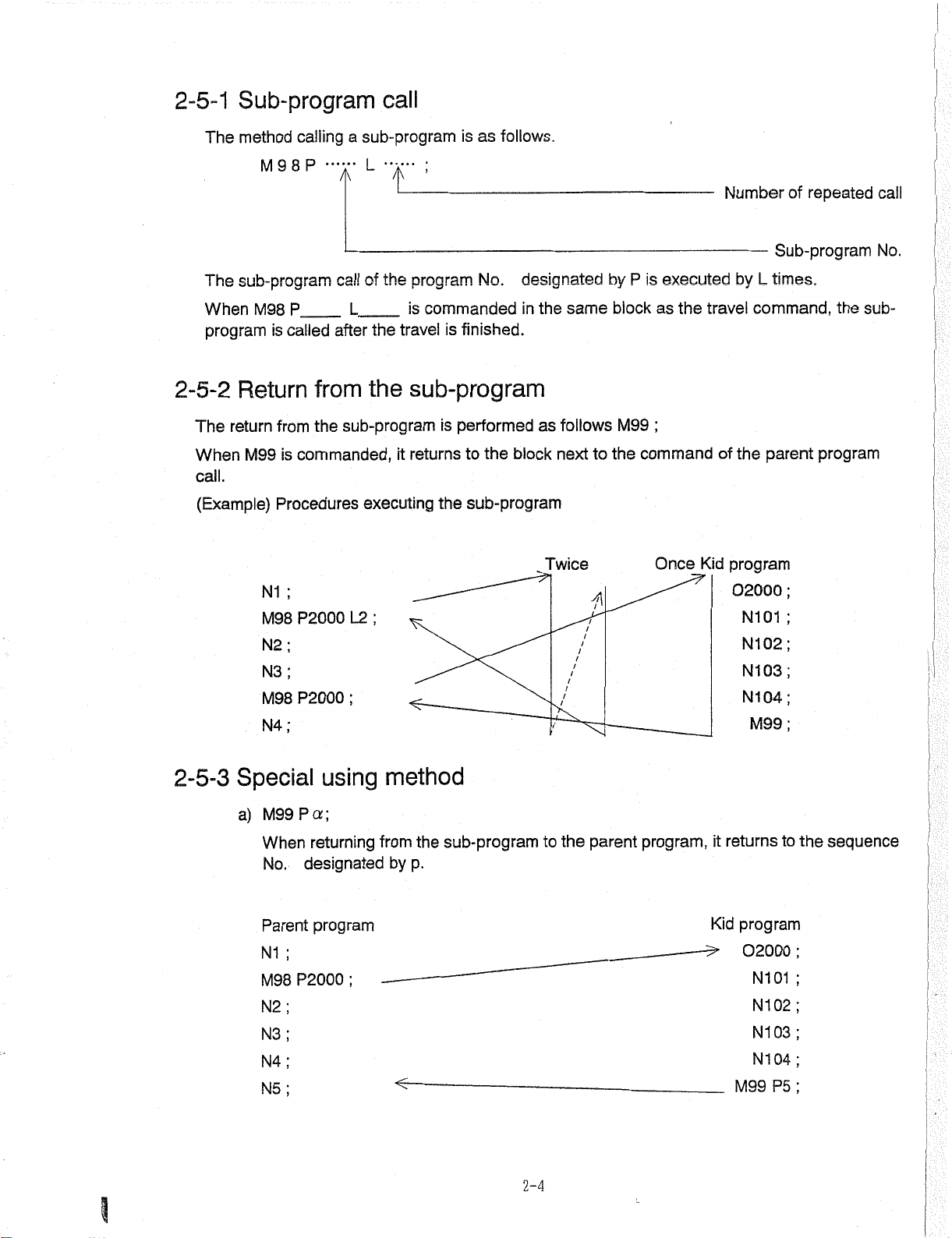
2-5-1
The
Sub-program
method
calling
sub-program
a
call
is
as
follows.
The
When
program
2-5-2
The
When
call.
(Example)
P
9
8
M
sub-program
called
is
P.
_
M98
Return
from
return
commanded,
is
M99
Procedures
;
N1
P2000
M98
;
N2
;
N3
P2000
M98
;
N4
L
A
of
call
_
L
after
from
the
the
sub-program
executing
L2
;
"i_i
the
program
commanded
is
travel
the
it
;
is
sub-program
is
performed
returns
the
designated
No.
the
in
finished.
as
the
block
to
sub-program
same
follows
next
Twice
7
to
by
the
is
P
block
M99
command
executed
the
as
;
Kid
Once
Number
by
travel
the
of
program
02000
of
Sub-program
L
times.
command,
parent
;
;
N101
;
N102
N103;
N104
;
M99
repeated
the
program
call
No.
sub¬
I
:
2-5-3
Special
M99
a)
P
When
No.
Parent
;
N1
P2000
M98
N2
N3
N4
N5
designated
using
a
;
returning
program
;
method
sub-program
the
from
by
p.
2-4
to
the
parent
program,
returns
it
Kid
program
02000
N101
N102
N103
N104
P5
M99
to
the
;
sequence
:
I
Page 17
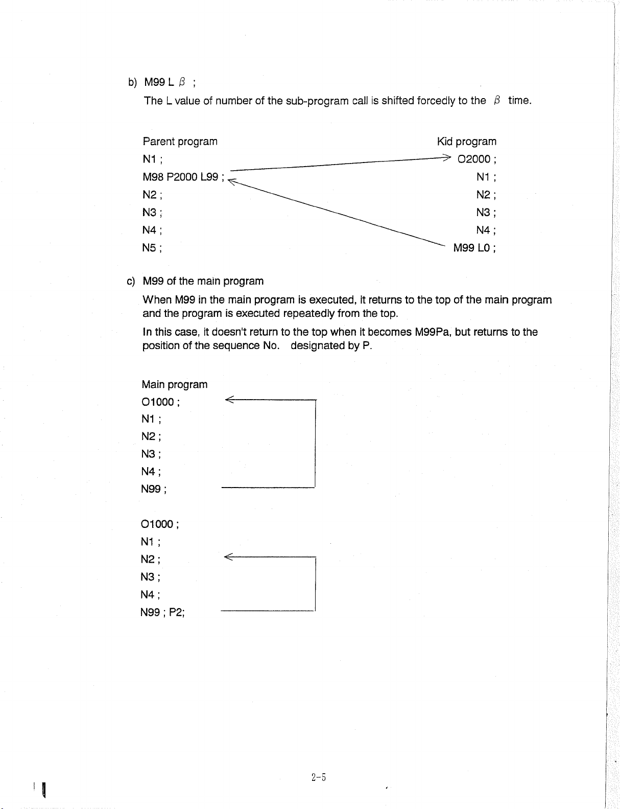
b)
M99
;
L
/3
TheLvalue
Parent
N1
M98
N2
N3
N4
N5
M99
c)
When
and
this
In
position
Main
program
;
P2000
the
of
M99
program
the
case,
of
program
numberofthe
of
;
L99
program
main
the
main
in
is
doesn't
it
the
sequence
program
executed
return
No.
sub-program
executed,
is
repeatedly
to
the
top
when
designated
from
by
call
is
returns
it
the
it
becomes
P.
shifted
to
top.
forcedly
Kid
the
top
M99Pa,
the
to
program
02000
N1
N2
N3
N4
M99L0
the
of
but
main
returns
/3
;
time.
program
the
to
01
N1
N2
N3
N4
N99
01
N1
N2
N3
N4
N99
000
;
000
;
;
;
<c
P2;
2-5
I
Page 18
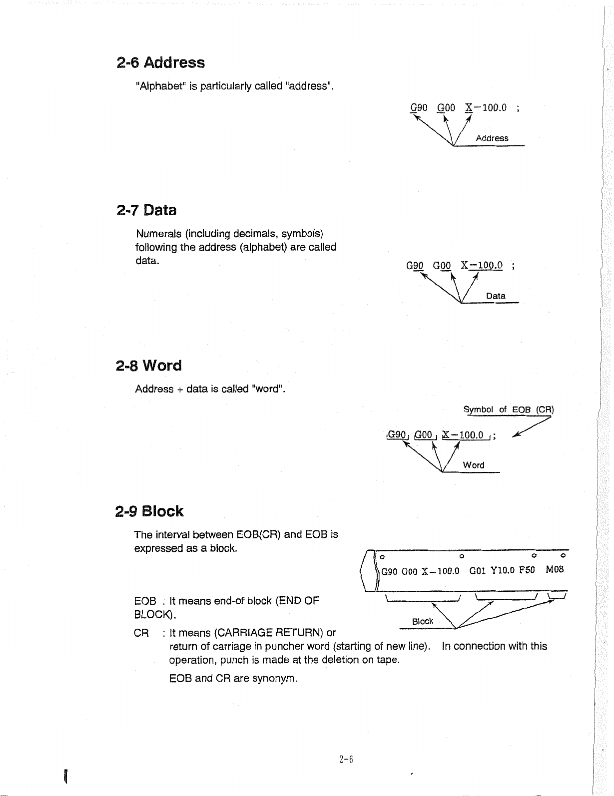
2-6
Address
"Alphabet"
2-7
Numerals
following
data.
2-8
Data
Word
particularly
is
(including
the
address
called
decimals,
(alphabet)
"address".
symbols)
are
called
G90
G90
GOO
GOO
100.0
X-
Address
X-100.0
Data
;
;
Address+data
Block
2-9
interval
The
expressed
EOB
BLOCK).
CR
between
as
means
:
It
It
:
means
return
operation,
and
EOB
is
called
EOB(CR)
block.
a
end-of
(CARRIAGE
carriage
of
punch
are
CR
"word".
(END
block
RETURN)
puncher
in
is
made
synonym.
and
at
EOB
OF
word
the
is
or
(starting
deletion
on
iG90
G90
new
of
tape.
1
GOO
GOO
Block
line).
i
X-100.0
X-100.0
In
Symbol
Word
o
G01
of
Y10.0
connection
EOB
F50
with
(CR)
o
this
O
M08
2-6
Page 19
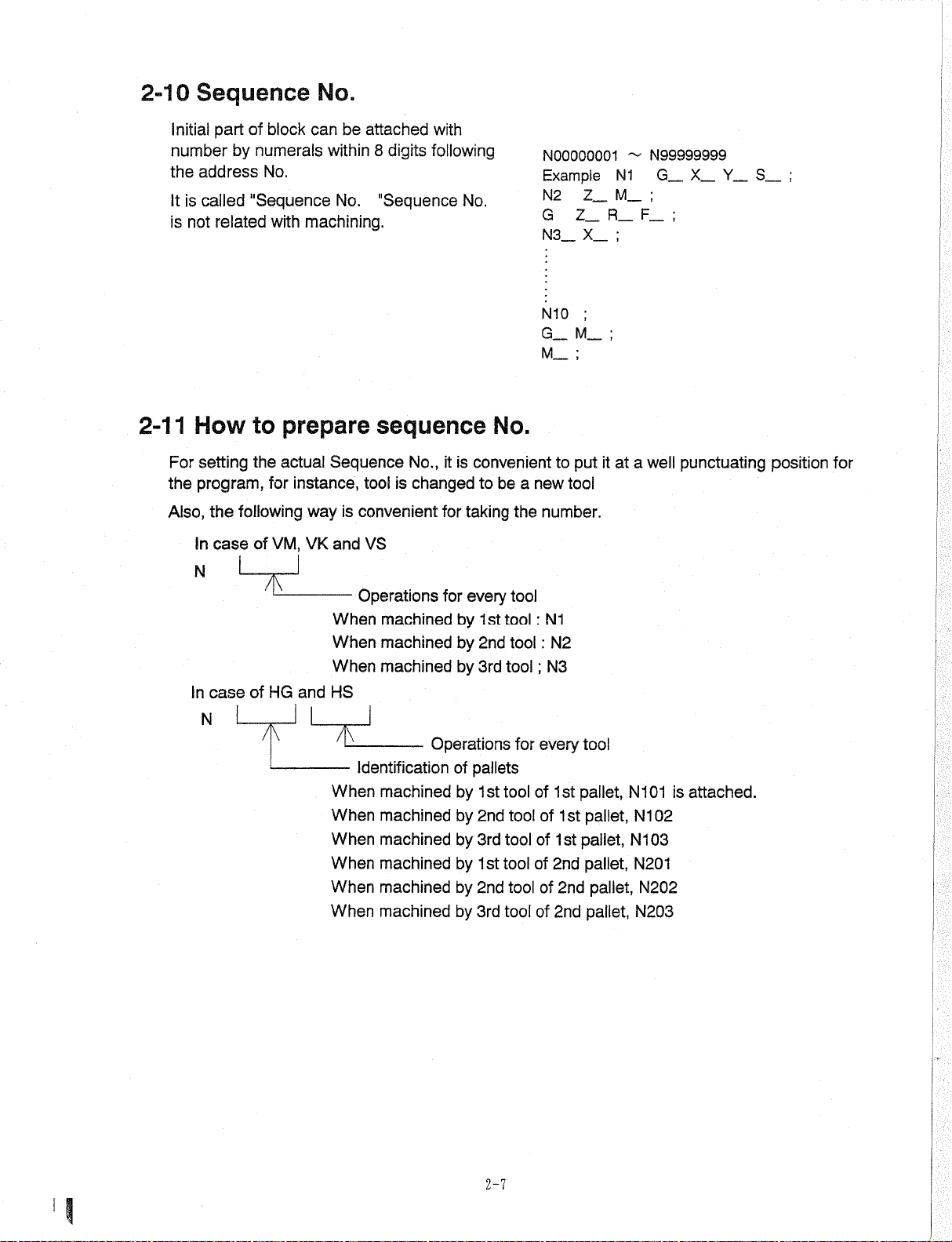
2-10
Sequence
No.
part
related
following
the
case
of
"Sequence
to
the
of
Initial
numberbynumerals
the
address
It
is
called
is
not
2-11
How
For
program,
the
Also,
in
setting
N
case
of
In
block
can
No.
with
machining.
prepare
actual
instance,
for
way
VM,
VK
and
HG
be
attached
8
within
No.
digits
"Sequence
sequence
Sequence
tool
is
convenient
and
VS
—
Operations
When
When
When
HS
machined
machined
machined
following
No.,
is
changed
with
it
for
for
No.
is
by
by
by
No.
convenient
be
a
to
every
1st
2nd
3rd
the
tool
tool
tool
tool
taking
N00000001
Example
Z_
N2
Z_
G
_
X_
N3
;
N10
_M_
G
_
;
M
put
to
new
tool
number.
:
N1
N2
:
;
N3
N99999999
~
X_
Y_
G_
N1
_
;
M
_
_
F
a
well
;
punctuating
R
;
;
at
it
S_
position
;
for
N
/\
7K
Identification
When
When
When
When
When
When
machined
machined
machined
machined
machined
machined
Operations
of
pallets
1st
2nd
3rd
1st
2nd
3rd
tool
tool
by
by
by
by
by
by
for
tool
tool
tool
tool
every
1st
of
of
1st
of
1st
of
2nd
2nd
of
of
2nd
tool
pallet,
pallet,
pallet,
pallet,
pallet,
pallet,
N101
N102
N103
N201
N202
N203
is
attached.
2-7
Page 20
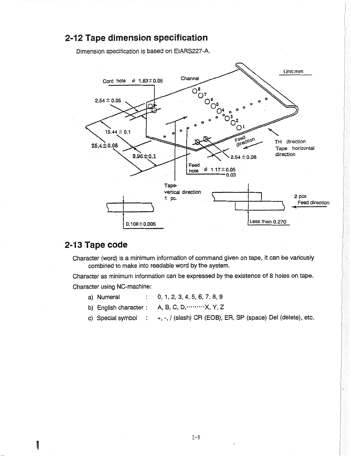
2-12
Tape
dimension
specification
Dimension
Cord
2.54
25.4±0.08
specification
hole
<£
±
0.05
±
15.44
0.1
9.96
is
1.83
±0.1
based
±0.05
on
EIARS227-A.
Channel
o
o
Tape-
vertical
1
direction
pc.
o8
Feed
hole
°7
o
<t>
s
°ot
•
°OL.
1.17±0.05
.
•
ol
2.54
°
±0.08
Unit:mm
o
o
X
direction
TH
Tape
horizontal
direction
pcs
2
Feed
direction
2-13
Character
Character
Character
Tape
(word)
combined
as
using
a)
Numeral
English
b)
c)
Special
0.1
code
minimum
a
is
make
to
minimum
NC-machine:
character
symbol
08±
0.005
information
into
readable
information
0,
A,
+,
can
1,2,
B,
-,
word
be
3,
C,
(slash)
/
command
of
the
by
expressed
6,
5,
4,
D,
CR
system.
by
7,
8,9
•X,
Y,
(EOB),
given
the
Z
ER,
Less
tape,
on
existence
(space)
SP
than
it
of
0.270
can
8
Del
holes
variously
be
on
(delete),
tape.
etc.
3
2-8
Page 21
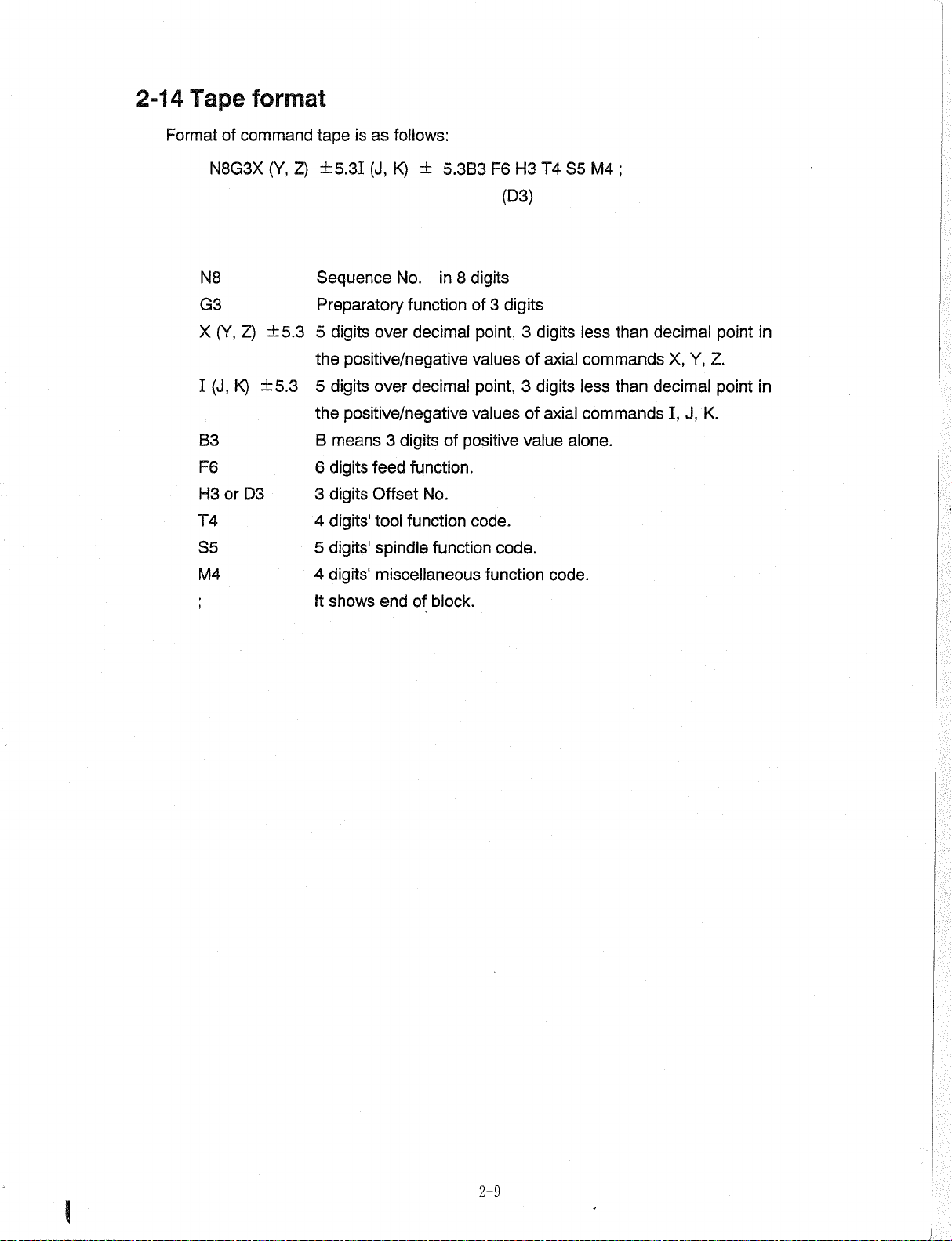
2-14
Tape
format
Format
N8
G3
X
I
B3
F6
H3orD3
T4
S5
M4
of
command
N8G3X
Z)
(Y,
(J,
K)
(Y,
±5.3
±5.3
tape
2)
±5.31
Sequence
Preparatory
digits
5
the
positive/negative
digits
5
the
positive/negative
B
means
digits
6
3
digits
digits'
4
digits'
5
4
digits'
shows
It
as
is
follows:
K)
±
(J,
No.
function
over
decimal
over
decimal
digits
3
feed
function.
Offset
tool
spindle
No.
function
function
miscellaneous
endofblock.
8
F6
digits
3
of
5.3B3
in
point,
values
point,
valuesofaxial
of
positive
code.
code.
function
H3
(D3)
digits
3
of
3
value
T4S5M4
digits
less
axial
commands
digits
less
commands
alone.
code.
;
than
than
decimal
X,
Y,
decimal
I,
J,
Z.
K.
point
point
in
in
2-9
Page 22
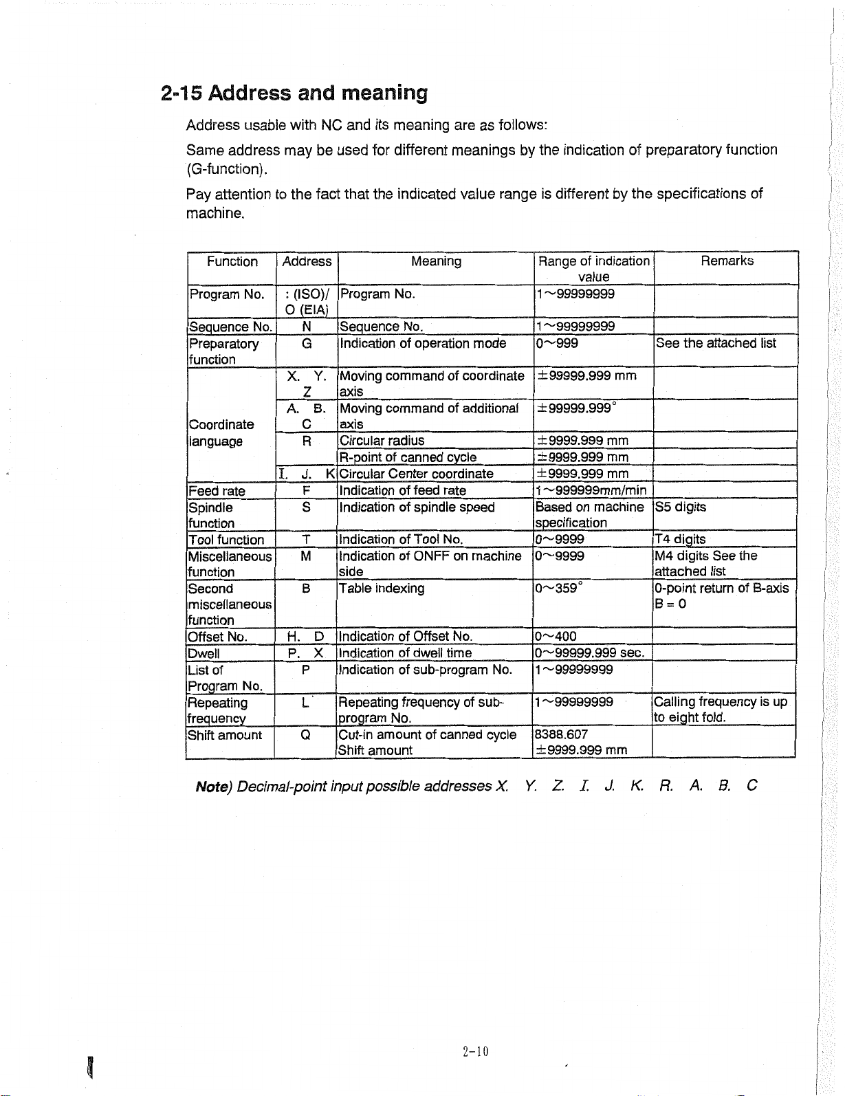
2-15
Address
Address
Same
(G-function).
usable
address
and
with
may
meaning
and
NC
used
be
meaning
its
for
different
are
follows:
as
meanings
by
the
indication
preparatory
of
function
J
Pay
attention
machine.
Function
Program
Sequence
Preparatory
function
Coordinate
language
Feed
Spindle
function
Tool
Miscellaneous
function
Second
miscellaneous
function
Offset
Dwell
List
Program
Repeating
frequency
Shift
No.
No.
rate
function
_
No.
of
No.
amount
the
to
Address
(ISO)/
:
(EIA)
0
N
G
X.
Z
A.
C
R
J.
I.
F
S
T
M
B
H.
P.
P
L
Q
fact
Program
Sequence
Indication
Moving
Y.
axis
Moving
B.
axis
Circular
R-point
Circular
K
Indication
Indication
Indication
Indication
side
Table
Indication
D
Indication
X
Indication
Repeating
program
Cut-in
Shift
that
the
indicated
No.
command
_
command
radius
of
Center
_
indexing
of
of
of
No.
amount
amount
Meaning
No.
of
operation
of
of
canned
of
of
of
of
frequency
cycle
coordinate
feed
rate
spindle
Tool
No.
ONFF
Offset
dwell
time
sub-program
_
canned
of
_
value
mode
coordinate
additional
speed
on
machine
No.
No.
of
sub-
cycle
range
Range
1
1
0~999
±99999.999
±99999.999°
±9999.999
±9999,999
±9999.999
1
Based
specification
0~9999
0~9999
0~359°
0~400
0
1
1
8388.607
±9999.999
the
indication
of
value
by
different
is
~99999999
~99999999
mm
mm
mm
mm
'~999999mm/min
on
machine
"-'99999.
~99999999
-99999999
999
mm
sec.
specifications
Remarks
the
digits
digits
digits
=
eight
0
attached
See
list
return
frequency
fold.
See
S5
T4
M4
attached
0-point
B
Calling
to
the
of
of
list
B-axis
is
up
Note)
Decimal-point
input
possible
addresses
2-10
X.
Y.
Z.
R.
J.
I.
K.
A.
B.
C
Page 23
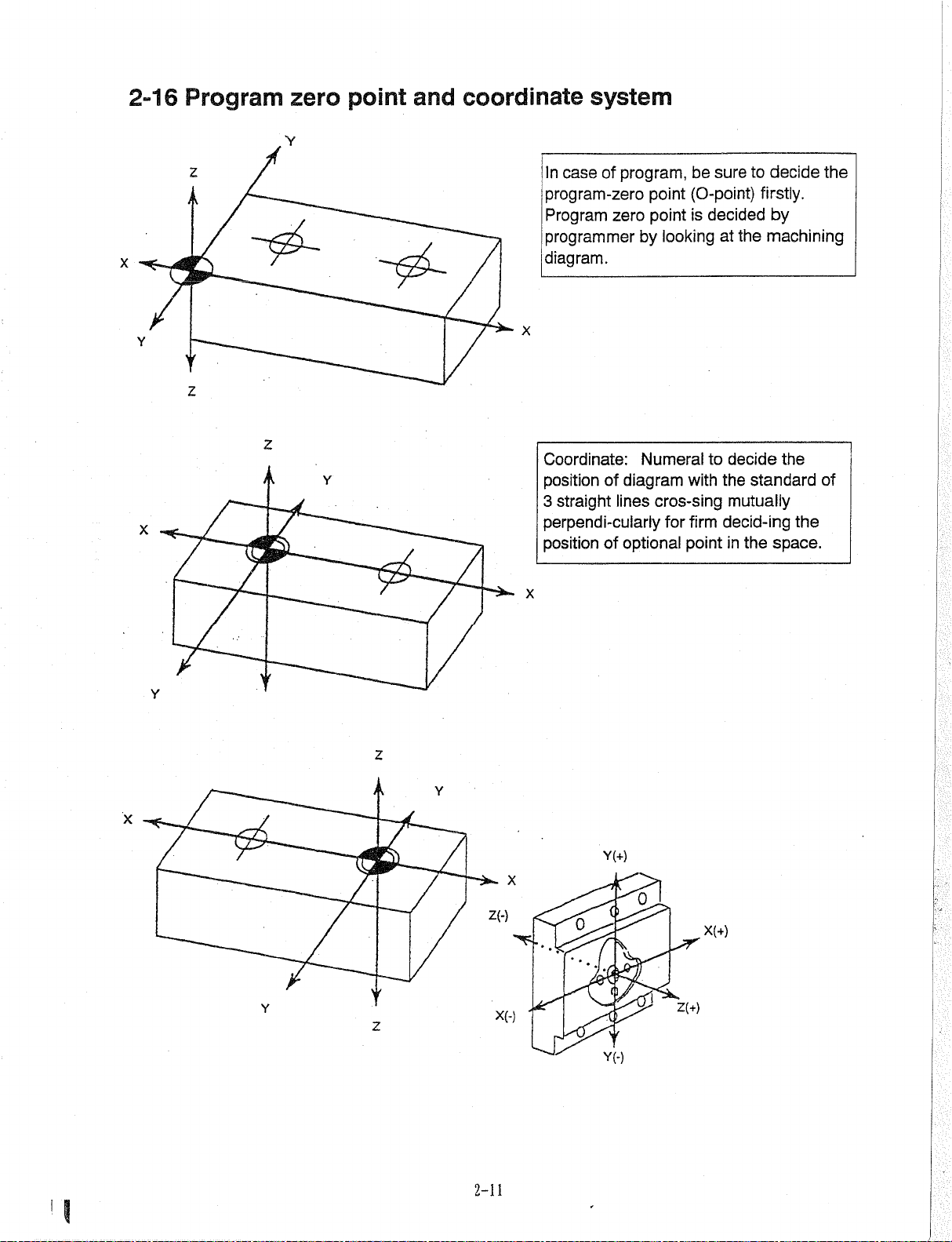
2-16
Program
zero
V
point
and
coordinate
system
z
X
Y
case
In
program-zero
Program
programmer
diagram.
X
program,
of
zero
by
point
point
looking
be
(O-point)
is
to
sure
decided
the
at
decide
firstly.
by
machining
the
z
z
decide
for
to
with
firm
point
the
mutually
decid-ing
in
of
diagram
lines
Numeral
cros-sing
Coordinate:
Y
*
X
position
3
straight
perpendi-culariy
positionofoptional
X
the
standard
the
the
space.
of
Y
Z
Y
X
Y(+)
X
Z(-)
X(+)
K
Y
t
z
X(-)
Y(-)
Z(+)
?
2-11
Page 24
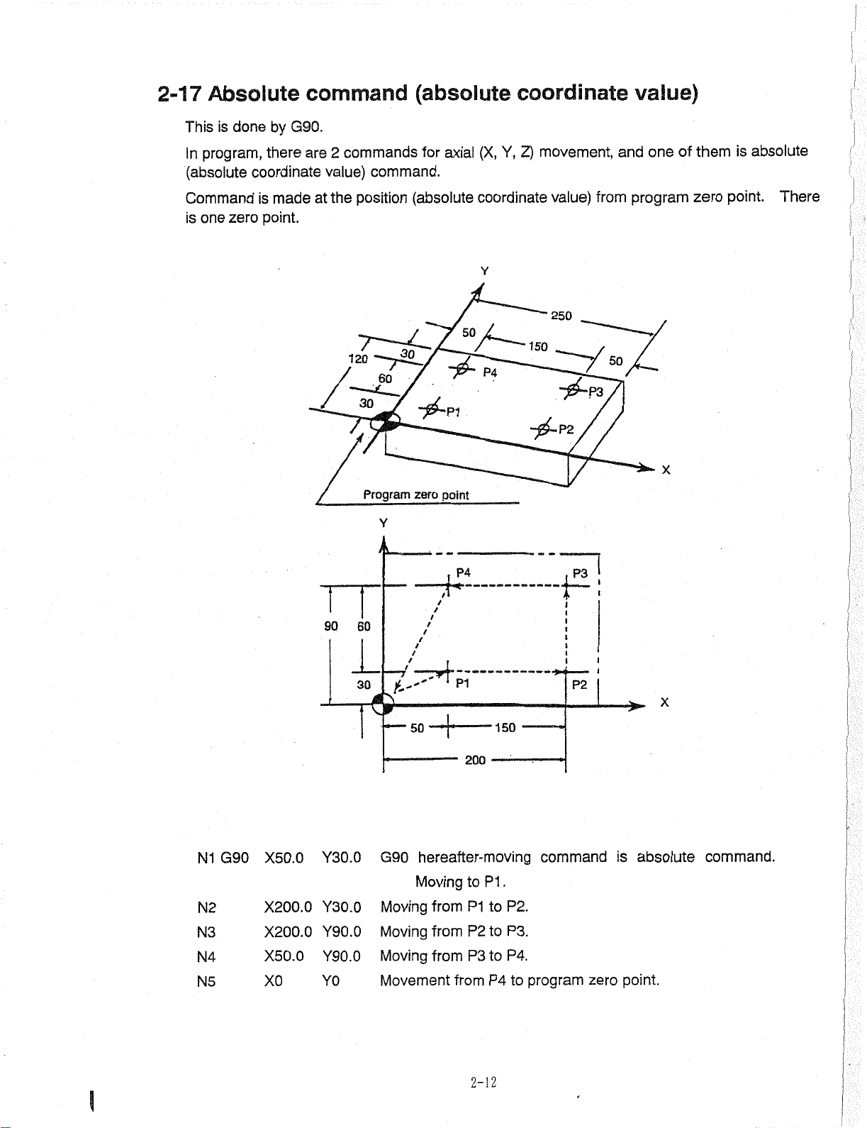
2-17
This
In
(absolute
Absolute
is
done
program,
there
coordinate
command
G90.
by
are
commands
2
value)
command.
(absolute
for
axial
(X,
coordinate
Z)
Y,
movement,
value)
one
and
of
them
is
absolute
1
r.
Command
zero
one
is
is
made
point.
at
the
120
position
30
.60
30
Program
Y
(absolute
,
-ÿ-P1
zero
point
P4
coordinate
Y
50
P4
value)
250
150
-ÿ-P2
from
50
program
X
zero
point.
There
I
N1
N2
N3
N4
N5
G90
X50.0
X200.0
X200.0
X50.0
X0
90
1
Y30.0
Y30.0
Y90.0
Y90.0
Y0
60
30
t''
&
—
G90
Moving
Moving
Moving
Movement
t
t
PI
200
to
P1
P2
P3
from
P1
to
to
to
P4
150
.
P2.
P3.
P4.
50
hereafter-moving
Moving
from
from
from
i
J
P2
commandisabsolute
program
to
zero
point.
X
command.
1
2-12
Page 25
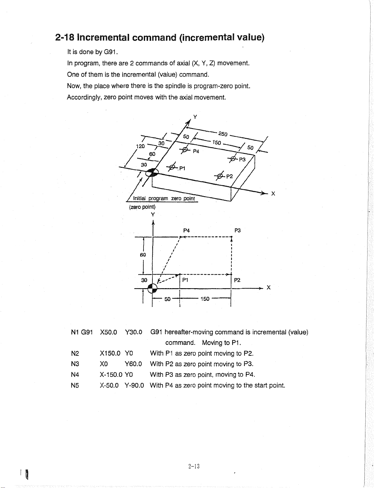
2-18
It
Incremental
is
done
by
G91
command
.
(incremental
value)
program,
In
of
One
Now,
Accordingly,
themisthe
the
place
there
where
zero
are
2
commands
incremental
there
point
moves
7
'
120
30
Initial
point)
(zero
60
of
axial
is
(value)
the
with
command.
spindle
the
axial
is
_
30
/
—
60
program
Y
-
~ÿ-.P\
point
zero
P4
/
t
/
/
movement.
Z)
Y,
(X,
program-zero
movement.
Y
250
150
P4
~ÿ~P3
-f£~P2
1
point.
SO
X
P3
N1
N2
N3
N4
N5
G91
X50.0
X150.0
X0
X-150.0
X-50.0
Y30.0
Y0
Y60.0
Y0
Y-90.0
30
t-''
50
*
—
hereafter-moving
G91
command.
P1
P2
P3
P4
as
as
as
as
With
With
With
With
PI
zero
zero
zero
zero
150
Moving
point
point
point,
point
P2
command
P1
to
moving
moving
moving
moving
to
to
to
is
incremental
.
P2.
P3.
P4.
to
the
start
X
(value)
point.
2—
3
1
Page 26
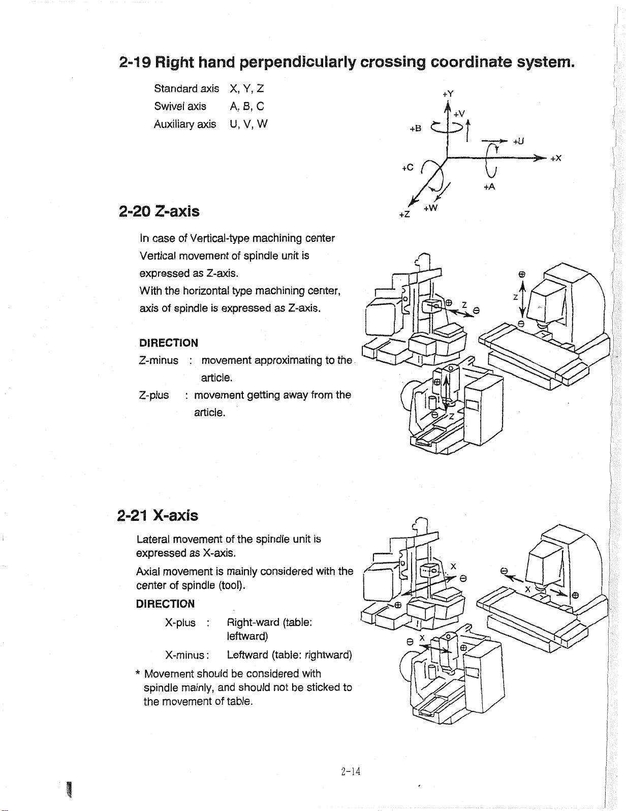
2-19
2-20
Right
Standard
Swivel
Auxiliary
axis
Z-axis
hand
axis
axis
perpendicularly
Y,
X,
Z
A,
B,
C
U,
V,
W
crossing
+B
+c
+z
coordinate
+Y
'k+V
u
+A
J/
+W
system.
+U
+x
In
Vertical
expressed
With
axis
DIRECTION
Z-minus
Z-pius
2-21
Vertical-type
of
case
movement
Z-axis.
as
horizontal
the
spindleisexpressed
of
:
movement
article.
movement
:
article.
X-axis
machining
spindle
of
machining
type
approximating
getting
unit
as
away
center
is
center,
Z-axis.
from
to
the
the
si
P
r
©
\
J
z
Le
Y
V,
©
Lateral
expressed
Axial
center
DIRECTION
*
movement
movement
spindle
of
X-plus
X-minus
Movement
spindle
the
mainly,
movement
as
X-axis.
is
(tool).
:
:
should
and
of
the
of
spindle
mainly
considered
Right-ward
leftward)
Leftward
be
should
table.
(table:
considered
not
unit
(table:
rightward)
with
be
is
with
sticked
the
to
2-14
.©
p
©
*
••To.
x
©
©
X
©
C3
\
Page 27
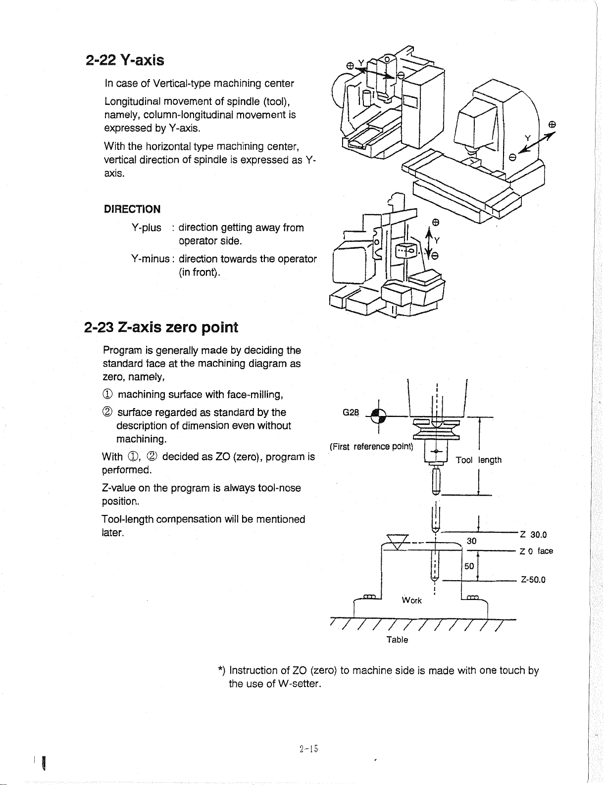
2-22
Y-axis
In
Longitudinal
namely,
expressed
With
vertical
axis.
DIRECTION
2-23
Program
standard
zero,
(D
©
With
performed.
case
Z-axis
machining
surface
description
machining.
Vertical-type
of
movement
column-longitudinal
by
Y-axis.
the
horizontal
direction
Y-plus
Y-minus
:
:
zero
generally
is
face
at
namely,
surface
regarded
of
(D,
decided
©
machining
of
type
machining
of
spindle
direction
operator
direction
front).
(in
point
made
machining
the
with
as
standard
dimension
as
ZO
spindle
movement
is
expressed
getting
side.
towards
away
the
by
deciding
diagram
face-milling,
by
without
even
(zero),
center
(tool),
is
center,
as
from
operator
the
as
the
program
Y-
is
m
\
G28
(First
$
reference
r
point)
C3
t
©
/>
Y
©
e
I
.
length
Tool
Z-valueonthe
position.
Tool-length
later.
compensation
program
is
always
will
*)
Instruction
the
tool-nose
be
mentioned
use
of
of
ZO
(zero)
W-setter.
2-15
/
/
machine
to
/
/
Table
side
Work
///////
is
made
30
50
with
one
touch
Z
30.0
0
Z
Z-50.0
by
face
Page 28
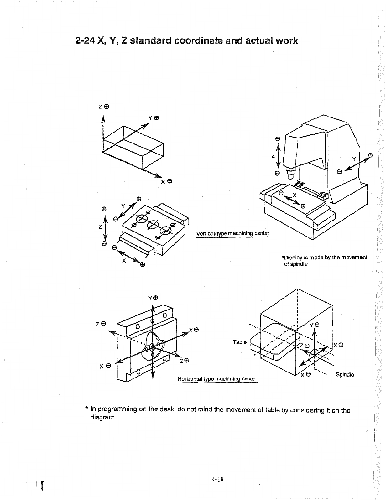
2-24
X,
z©
Y,
Z
standard
coordinate
Y
©
and
actual
work
A
z
Y
j
v
©
X©
e
Z
Z©
X
*
A
V
*
e'
©
>5
©
/J
X
0
’
©
Vertical-type
Y©
0
,x©
•
.
z©
Horizontal
type
machining
Table
machining
center
center
©
•Display
of
spindle
©
is
JÿX©
\
madebythe
Y©
X©
k
movement
Spindle
i
In
programming
*
diagram.
on
the
desk,
do
not
mind
the
2-16
movement
of
table
by
considering
on
it
the
Page 29
3.
M,
S,
T,
F,
FUNCTIONS
B
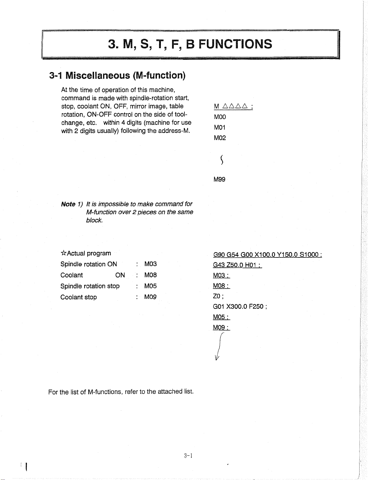
3-1
Miscellaneous
the
At
commandismade
stop,
rotation,
change,
with
Note
time
coolant
ON-OFF
etc.
2
digits
It
1)
M-function
block.
of
operation
ON,
within
usually)
is
impossible
(M-function)
this
of
spindle-rotation
with
mirror
OFF,
control
on
digits
4
following
to
2
over
make
pieces
machine,
image,
the
side
(machine
address-M.
the
command
on
table
of
for
the
start,
tool-
use
same
for
AAAA
M
MOO
M01
M02
S
M99
;
For
Spindle
Coolant
Spindle
Coolant
list
the
program
rotation
rotation
stop
M-functions,
of
ON
stop
ON
refer
to
M03
M08
M05
M09
the
attached
list.
G90
G43
M03
M08
ZO;
G01
M05
M09
V
GOO
G54
Z50.0
:
:
X300.0
:
:
H01
F250
X100.0
:
;
Y150.0
S1000
:
3-1
Page 30
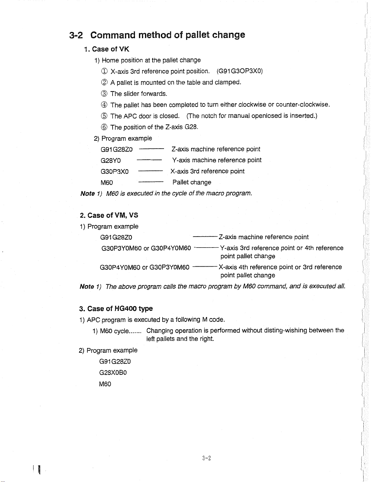
3-2
Command
method
of
pallet
change
.
1
Note
Case
2.
Case
of
1)
Home
X-axis
<2>
(D
A
(D
The
@
The
(D
The
The
©
Program
2)
G91G28Z0
G28Y0
G30P3X0
M60
M60
1)
ofVSVS,
VK
position
3rd
pallet
slider
pallet
APC
position
example
is
executed
VS
at
reference
mounted
is
forwards.
has
door
of
the
been
closed.
is
the
the
in
change
pallet
point
the
on
completed
Z-axis
Z-axis
Y-axis
X-axis
Pallet
cycle
position.
and
table
to
notch
(The
G28.
machine
machine
reference
3rd
change
the
of
(G91
clamped.
either
turn
for
reference
reference
macro
G3OP3X0)
clockwiseorcounter-clockwise.
inserted.)
manual
point
point
program.
openlosed
point
is
!;
!
i
,
Program
1)
Note
Case
3.
APC
1)
Program
2)
example
G91G28Z0
G30P3Y0M60
G30P4Y0M60
1)
1)
M60
G91G28Z0
G28X0B0
M60
above
The
HG400
of
program
cycle
example
Z-axis
program
M
code.
performed
is
right.
-Y-axis
X-axis
point
G30P4Y0M60
or
G30P3Y0M60
or
the
following
a
operation
and
macro
the
program
type
executed
is
.......
calls
by
Changing
left
pallets
point
machine
3rd
pallet
4th
pallet
by
M60
without
reference
reference
change
reference
change
command,
disting-wishing
point
point
or
4th
3rd
or
point
andisexecuted
between
reference
reference
all.
;
the
(
3-2
Page 31

4.
CaseofHG500
type
1
There
.
Program
2.
1)
In
G91
G30
G30
1)
2)
3)
case
are
M60
M61
M62
M60
The
a
G28
P3
P4
kinds
three
cycle
.......
cycle
.......
cycle
.......
APC
of
Changing
pallets
left
pallet
pallet
on
in.
on
in.
A
carried
A
carried
programs
operation
and
the
machine
machine
follows:
as
performed
is
right.
carried
is
carried
is
example
cycle
contents
is
pallet
ZO
BO
YO
XO
YO
XO
left
M60
M60
of
side
M60
M60
canned
In
End
case
G91
G30
G30
cycle
pallet
a
G28
P4
P3
is
XO
XO
ZO
right
BO
YO
YO
side
M60M60'~.
out
out
without
left
side
right
side
disting-wishing
side
right
A
and
side
0
G91
pallet
A
right
A
A
1234
G28
XO
M06
left
left
YO
on
side.
side
ZO
machine
pallet
-
and
G28
M60
T01
out
between
pallet
pallet
is
carried
is
carried
the
is
is
in.
2)
In
case
In
G91
G30
G30
M61
The
case
The
G28
P3
P4
and
contents
pallet
a
contents
pallet
a
ZO
XO
XO
L
In
is
BO
YO
YO
M62
left
is
case
left
In
M60
M60
cycle
M61
of
M61
side
pallets
(ÿEncP)
of
M62
M62
side
pallets
case
canned
case
In
are
both
canned
case
In
are
both
cycle
a
sides
G91
G30
G30
cycle
pallet
a
sides
pallet
G28
P4
P3
is
is
ZO
XO
XO
right
right
YO
YO
side
BO
side
M60
M60
0001
0
G28
G91
XO
G28
M61—A
M98
-M62---A
P2345
M98
M30
ZO
YO
right
P1234’"Pr°gram
side
left
pallet
side
machining.
pallet
machining.
carried
is
for
carried
is
A
for'
B
in.
work
in.
Work
End
3-3
Page 32

5.
CaseofHS
type
1)
APC
1)
2)
Program
program
M60
cycle
example
G30
G91
BO
M60
a
following
pallets
ZO
P4
by
operation
and
the
right.
is
executed
Changing
.......
YO
XO
code.
M
is
performed
without
disting-wishing
between
the
left
i
:
;
{
I
r
l
3-4
;
i
Page 33

Command
3-3
Make
A.
5
digits
direct
following
method
command
the
address
for
of
spindle
S.
spindle
speed
by
speed
AAAAA
S
(S-function)
Command
B.
Programming
C.
Change
Spindle
Change
rotation.
Reverse
Spindle
Change
value
lower
to
rotation
spindle
rotation
stop
the
speed
example
feed,
speed
for
500
min*1
to
5000
rotation.
min*1
for
S45
/
S4500
S500;
M03;
S5000
M04;
M05;
S500
M03;
(45
(4500
min*1)
/
min'1)
3
Note
Note
Note
Note
Note
Note
1)
S-command
Whereas,
2)
3)
4)
5)
6)
S-command
With
set.
By
spindle
mode,
to
With
auto-mode
movement.
movement
Set
Simultaneous
axial
spindle
Changing
damage.
makes
case
in
rotation
thereafter,
command
after
stop
speed
speed
S-command
of
except
the
by
Simultaneous
the
high/low
in
with
for
auto-mode
with
auto-mode
rotating
for
of
end
gear
change
alone,
during
max/min
(MDI,
induce
will
the
spindle
axial
movement
commandofaxial
axial
movement.
speed
shift
area,
feeding
in
3-5
and
rotation,
spindle
Memory,
by
gear-shift
operation
spindle
change
speed,
“alarm".
manual
M03
with
does
the
upperower
spindleisstopped
tape),
is
or
not
again.
M04
allowed
mode
movement
operation
not
speed
will
is
rotate.
maxin
induce
with
made
for
rotation.
for
speed
can
by
rotation
will
fear
cause
of
tool
M05
automatically.
be
manual
with
Page 34

3-4
Tool
No.
call
:
(T-function)
A.
Command
generally)
address-T.
stand-by
the
code
This
commanded.
B.
Program
A
Case
Case
C.
positioning
While
coordinate
No.20,
Tool
is
of
is
example
calling
in
calling
in
operation
making
values
made
numerals
execution,
After
position,
effective
the
the
rapid
and
then,
within
in
and
until
Tool
Tool
No.20
feed
X200.0
is
it
4
digits
following
tool
arm
the
next
15
No.
absolute
to
Y150.0,
hold
(2
the
is
called
is
hold.
T
during
select
arm.
in
digits
is
the
to
T
T15
G90
AAAA
:
GOO
X200.0
Y15Q.0
T20:
Relation
D.
At
AtN2with
change
After
spindle.
Tool
E.
Then,
No.
N1
is
,
the
No.
with
T01
call
T01
operation
end
same
is
T_No.
same
the
change:
tool
.
spindle,
for
of
operation,
as
T01
is
with
as
make
tool.
with
~T30
Tool
automatic
T01
Magazine
kept
is
(*Magazine
by
No.
No.
)
at
the
N1
N2
Tool
isT
T01
:
M06
:
mounted
AA.
Magazine
on
V
No.
3-6
Page 35

F.
time
At
position
current
of
and
change,
tool
for
simultaneous
next
tools.
there
change
is
stand-by
of
the
calling
Case
position.
Simultaneously
spindle
and
stand-by
the
Y,
X,
G.
(Second
H.
Note
Z-axial
Precaution
There
1)
zero
Tool
with
change,
position.
positions
point)
tool
for
a
limit
is
No.15
x,
y-axial
Tool
at
change
on
the
to
stand-by
movement
No.15
timeoftool
tool
is
shape,
called
change
do
not
to
T15
(Actual
G54
(Case
(CaseofHG)
(CaseofVM)
other
use
;
programming
G90
GOO
VK)
of
tool
than
example)
X100.0
JG91
YO
G30
[G30X0Y0
G30
G91
P3
G30
limited.
S100
ZO
XO
XO
T15
ZO
;
Note
Note
2)
In
advance
3)
In
of
commanding
case
is
of
case
(ATC
M06
made
VM,
canned
VG,
to
TX
the
VK
and
cycle).
XM06
next.
HG,
of
spindle-tool
exchange
tool
again,
is
no
automatically
tool
exchange
by
done
is
done,
command
the
and
3-7
Page 36

Programming
3-5
example
of
tool
change
(Case
of
VM,
VK,
VS)
9
Note)
(Chip
M31
Keeping
spindle
T01
stand-by
T02
M06
(ATC
of
Case
M15
G91
G30
(TXX)
Case
TXX
G91
G30
G30
The
command.
With
the
By
ment
VK
;
G30
G91
M06
VM,
of
;
G30
P3
XO
XO
P2
above
the
order
adding
of
cycle)
;
;
VS,
-*
X.
option,
is
X
start)
operation,
tool
can
conveyor
tool-change
canned
;
ZO
Y0M19;
;
VS
P2X0ZOM1O6;
M06
M107
operations
VM,
of
Z
the
and
Z
performed
are
exchange
simultaneous
be
done.
is
by
M06
done
move¬
in
01234
G17G40
N1
;
T01
M06
T02
;
G54 G90
Z30.0
G43
;
M03
Machining
;
N2
T02
M06
;
T03
G54
G90
G43
Z30.0
;
M03
Machining
;
N8
M06
T08
;
T01
G90
G54
Z30.0
G43
Machining
S
G28
G91
XO
G28
;
M30
;
M31
G80
;
GOO
XO
H01
;
X100.0
GOO
H02
program
;
GOOXOYO
H08
program
;
ZO
YO
;
;
S300
YO
;
program
;
S800
;
;
Y-50.0
;
S1000
;
3-8
i,
Page 37

3-6
Programming
example
of
tool
change
3-6-1
1
.
1)
2)
3)
2.
1)
0
0098
G40
G91
G30
G90
Case
There
Program
are
ATC
position
A
method
A
method
the
ATC
Performing
Registered
M19
G80
G30
ZO
XO
YO
M99
HG
of
kinds
three
return
of
using
performing
of
time)
example
ATC
sub-program
as
M09
of
is
performed
ATC
position
program
ATC
canned
position
ATC
return
of
of
main
by
(available
cycle
return
sub-program.
by
position
ATC
follows:
as
HG
sub-program.
or
by
arm
and
return.
O
G91
G28
M98
T01
G54
changing
swing
1234
G28
XO
YO
P98
M06
G90
Machining
.....
parameter)
the
operation,
ZO
GOOXOYO
program
(effective
S300
102
to
save
A
method
2)
Registered
M15
G30Z0M19
G91
XO
G20
TXX
YO
M06
of
as
using
ATC
canned
ATC
canned
cycle
cycle.
in
SEICOS.
M98
T02
1234
O
G91
G28
T01
G54
T02
P98
M06
ZO
G28
XO
YO
M06
GOO
G90
.Machining
M06
XO
YO
S300
program
102
1
3-9
Page 38

Performing
3)
The
(D
(2)
(3)
Note
Note
contests
Axes
position.
M09,
Arm
Axis
position.
1)
Operation
feed
2)
Take
interfere
ATC
of
X,
M05,
swing
comes
override
care
position
the
operation.
of
Y,
are
Z
are
M19
operation
40mm
to
3)
of
will
is
that
tool
fixture
with
return
returned
performed.
be
will
before
be
done
100%.
noses
and
so
and
to
start
the
when
do
on.
ATC
ATC
not
arm
when
rapid
swing
Z
operation
1234
0
G91
G28
G28
XO
G30
G91
G90
G54
s
G80
G30
G91
s
a
time.
at
Z0
Y0
X0
Y0
Z0
XO
GOO
.Machining
XOYO
ZO
T01
S300
YO
program
T02
\
M06
TO2
M06
3-10
\
Page 39

3-6-2
Case
of
HS
This
operated
is
Fixed
M06
N1
G30Z0M115
cycle
N2G30Y0P3X0TXX
N3
N4
N5
N6M116
XO
G30
M06
P3X0M107
G30
[Explanation]
X
:
Spindle
Calling
Spindle
M106:
TX
by
ATC
position
waiting
tools
fixed
M106
deciding,
position
instantly
=
cycle
registered
shutter
of
tools
completed
in
close
called.
by
SEICOS.
O
G91
G28
T01
G54
l
T02
,
tools
x
TX
command.
1234
ZO
G28
YO
XO
M06
GOOXOYO
G90
S
Machining
S
M06
temporary
|
stop
S300
W
arm
T02
swing
spindle.
M06:
M107:
Note
Note
W
arm
W
arm
1)
P3
Kindsoftools
2)
position
XO
turn
swing
-*•
return
differs
are
tools
set
fixing.
-*
shutter
according
on
tool
layout
closed.
to
kinds
screen.
of
tools.
Be
sure
to
set
the
kind.
3-11
Page 40

Command
3-7
method
of
feed
speed
(F-function)
A,
Command
Commanded
interpolation,
B.
speed
ing
Actual
by
the
1
~5000.
program
Note
1)
Be
on
Note2)F-unitisthe
per
Note
3)
It
It
Note4)The
machine
Synchronous
the
distance
points
also,
numerals
sure
G01,
minute,
possible
is
called
is
range
feed
between
or
linear
by
command
put
to
G02,
moving
namely,
to
"reading
F-function
of
specification.
speedofplural
the
1
~999999
AAAA
F
G03.
omit
zero".
2
circular
moving
follow¬
amount
mm/min.
the
"0"
of
which
axes>
(mm)
upper
can
Command
F0001
F1
F0010
F0100
F5000
G01
G02
G03
digit
be
actually
X150-0
X200.0
X250.0
by
numeral.
commanded
1mm/min
F80
:
Y300.0
Y50.0
Actual
(minimum)
1mm/min
0mm/min
1
100mm/min
5000mm/min
R50.0
R100.0
depends
F4QQ
E3Q0
speed
;
;
on
the
Cutting
straight
case,
this
In
and
the
Example
The
The
cutting
The
When
axis
a
by
Example
The
But,
feed
lines.
cutting
G01
cutting
cutting
rotation
degree
cutting
speed
cutting
the
feed
feed
feed
feed
axis
unit,
L
=
commanded
feed
speed
G91
G01
V
Xa
speed
speed
speed
is
commanded
linear
and
G91
speed
feed
100.ÿ+90.ÿ
by
F
in
in
in
speed
of
Yb
the
the
the
is
each
axis
Zc
directionofX-axis
direction
direction
compensation
X100.
the
in
(mm)
becomes
code
composite
the
as
is
;
Ff
of
of
same
the
in
C90.
direction
follows.
Y-axis
Z-axis
is
made.
F200
rotation
of
speed
Fx
Fy
Fz
block,
;
that
=
=
=
it
tools
of
of
aXf
L
bXf
—
—
c*f
regarded
is
axis
which
axes
the
but
(C-axis)
on
move
commanded,
L
as
Fc
ak+b2+c2
V
=
straight
90.X
=
the
line
200
L
Ending
:
point
point
3-12
Page 41

3-8
Table-indexing
command
method
(B-f
unction)
HG
series
Command
By
machine
With
Rotationismade
the
specification,
absolute
BOO
B180
BOO
B90
B270
table
command,
rotation
minimum
B00~B359
short-circuit
by
address-B
direction
and
indexing
°
)
(1
(the
angle
the
is
left
B270
3-digit
numeral.
is
1
standard.
diagram
°
(
JTL
.
shows
B180
BOO
Spindle
the
case
B90
of
180°
).
B90
BOO
J!L
Spindle
position
Waiting
pallet
$
I
position
BOO-
i
J+L
Spindle
3-13
Page 42

;
r
.
Page 43

4-1
G
4.
G-FUNCTION
AAA
(preparatory
function)
]
it
shows
the
numeral
following
G.
That
concerning
Refer
to
list.)
meaning
the
of
Address
is,
it
is
the
list
of
digits
3
a
preparatory
the
movement
of
G-functions.
program-command
(usually
digits)
2
function
of
spindle
(The
attached
by
(tool).
GOO
G01
G02
G03
Positioning
Linear
Circular
Circular
interpolation
interpolation
interpolation
(rapid
feed)
(cutting
CW
CCW
feed)
'1
4-1
Page 44

4-2
GOO
called
is
It
rapid
next
the
(Positioning)
feed
rapid
is
feed
destination
made
from
or
rapid
the
(X,Y,Z).
traverse,
present
and
position
to
Y
A
Howtowrite
1)
Note
The
necessarily
2)
Note
Rapid
type
the
route
traverse
machine.
of
program
moving
at
limited
rate
time
the
to
different
is
is
not
straight
by
line.
the
40
Z
GOO
40
Current
X80.0
Y
A
position
Y40.0
Destination
80
X
.
.
50
+
:
Note
Note
3)
Movement
following.
Absolute
Incremental
4)
commanding
After
omit
to
may
command
command
efficacy
by
different
be
once,
(called
G90
G91
it
by
the
is
possible
modal).
about
Absolute
G90
command
GOO
X40.0
Incremental
GOO
G91
X40.0
45°
Y40.0
X80.0
command
Y40-Q
X40.0
40
Y40.0
Y0
X
80
:
:
4-2
z
Page 45

4-3
G01
(Linear
interpolation)
called
It
linear
position
Feed
linear
movement
to
(feed
rate
Howtowrite
a
moving
F
is
Example
cutting
the
next
program
amount
or
is
made
destination.
function)
(mm/min)
Start
point
cutting
from
F
is
necessary.
250
il
-f
“
feed,
the
per
1
4
100
and
current
minute
40
250
Current
position
400
t
™5*--
©
G01
G91
300
1t
50
I
100
50
200
10
T
150
clear
arrow
Put
40
mark.
X400.0
2
3
F200
Destination
43
X©
;
Start
1
2
3
4
point
-*
-*•
-*•
Rapid
1
positioning
Movement
2
speed
3
Rapid
4
Movement
speed
Starting
Return
by
point
rapid
traverse
by
traverse
by
the
to
traverse
rate
cutting
cutting
start
rate.
point
4-3
G91
GOO
X1
G01
X300.0
G00Y-100.0
G01X-300.0
G00X-1
00.0Y-1
00.0
F300
;
F300
50.0
Y250.0;
;
;
;
Page 46

4-4
G02,
G03
(circular
interpolation)
Rotary
It
direction
circle
Circular
Howtowrite
is
direction
called
(arc)
radius
circular
in
towards
X
Y_
cutting,
feed
the
Coordinate
(destination)
rate
the
is
commanded
program
and
moves
it
AAAA
F
commanded
with
end
of
value
along
point.
"R".
point
to
the
the
+Z
G02
G03
axis
X_
X_
G03
|G02
_R_
Y
_
Y
+Y
axis
A
G03)
G03
G02
_
R
F
F.
G02
+X
axis
R_
F_
Actual
Case
G02
Case
G03X-40.0
O
program
arc
of
X70.0Y0R70.0
arc
of
R-indication,
With
Whereas,
For
full
ordinary
Circular
Feed
1
2
R40.0
YO
full
circle,
circular
radius
per
rate
F150
F150
when
(circle
circle
command
command,
minute
;
;
arcisover
the
of
made
is
it
360°
by
possible
is
-40
cannot
)
the
Arc
180°
be
use
command
to
Y
2
:40
,
command
commanded
J,
I,
of
K.
it
Without
using
by
R-
with
R-indication.
with
using
I,
R70
_
J,
K.
.
R
Arc
even
1
70
by
the
use
the
In
center
(I
from
corresponds
of
I,
start
J,
to
K,
command
point.
X-direction,
made
is
Y-direction,
J
to
with
4-4
the
K
direction
Z-direction)
to
and
distance
in
view
of
the
circular
Page 47

4-5
G02,
G03
(program
example)
Program
Howtowrite
radius
by
example
R
absolute
indication
Y
80
40
--
20
--
Program
(00)/
zero
command
A
B
40
20
—
—
Start
point
30
point
program
B
C
R50
77
ou
(70.
80)
B
A
20
70
G90
G90
Feed
60R
60
G03
G02
F300
X70.0
X130.0
End
point
'
(130.20)
I
—
130
Y80.0
Y20.0
>-X
R50.0
C
R60.0
F300
F300
;
;
to
How
program
to
How
use
the
by
to
How
program
G90,
G91
write
by
write
write
by
,
F
radius
of
the
_
incremental
indication
R
absolute
J,
I,
incremental
use
are
command
K
of
I,
modals,
command
A
—
B
—
—
A
->
B
command
K
J,
-*
A
B
—
then,
B
C
program
>ÿ
B
C
B
C
those
after
the
G91
G91
G90
G90
G91
G91
second
G03
G02
G03
G02
G03
G02
digit
X20.0
X60.0
X70.0
X130.0
X20.0
X60.0
can
be
Y40.0
Y-60.0
Y80.0
Y20.0
Y40.0I
Y-60.0
omitted.
R50.0
R60.0
1-30.0
10
J-60.0
-30.0
J-60.0
10
F300
F300
J40.0
J40.0
;
;
F300
F300
F300
F300
;
;
;
;
4-5
I
Page 48

4-6
G02,
G03
(program
example)
Example
180°
to
How
by
radius
of
write
R
circular
absolute
indication
program
command
exceeding
program
->
A
B
C
B
—
Start
point
]
(Program
point)\
-50.oV
G90
G02
75.0
zero.
A
GOO
X-50.0
B
‘
R50.0
\
(X0.Y0I
Y75.0
25.0
;
Y25.0
R-50.0
F300
'
;
How
by
the
to
write
use
absolute
of
I,
J,
K
command
A
B
program
B
—
C
—
G90
G02
Y75.0
GOO
X-50.0
;
Y25.0
I0J-50.0
F300
;
I
.
L
*
4-6
Page 49

:
4-7
G02,
Full
In
*
With
G03
circular
case
of
absolute
(program
program
circle,
full
command
example
R
is
not
example)
used.
j
L
50.0
Start
->
A
B
point
Program
point
50.0
zero
A
G90
:o.o
GOO
.X70.0
X70.0
B
Y50.Q
Y50.0
X
;
With
Note
Note
incremental
(
1)
)
word
2)
explained
As
command
to
G17, G18,
command
can
be
omitted.
on
the
in
G18
case
G19
B
B
A
B
B
above
of
(Refer
B
0
A
—
-»
B
B
0
A
—
X-Y
plane,
X-Z
plane,
to
4-11)
the
and
(X70.0)
G30
X50.0
GOO
GOO
G91
(XO)
G03
X-20.0
GOO
same
can
command
X20.0
(YO)
be
G19
(Y50.0)
(Y50.0)
;
1-20.0
;
said
on
in
case
1-20.0
;
F100
Y-Z
of
;
plane.
plane.
Y-Z
F100
;
Whereas,
Refer
4-7
Page 50

4-8
Summary
on
GOO,
G01
,
G02,
G03
<D
©
<3>
Case
<D
destination
Moving
(D
destination
AVA
o
9
positioning
case
with
with
linear
rapid
traverse
interpolation
GOO
G01
G02
G03
_
_
Y
X
_
_
Y
X
_
_
X
Y
(Z
(Z
(Z
_
_
_
;
)
_
;
F
)
_
)
F
R
__
X
toward
toward
_
Y
GOO
GOO
G01
G01
_
(Z
X100.0
Z50.0
X100.0
Z-20.0
)
R
Y200.0
;
Y200.0
F100
_
F
;
F250
;
;
Moving
<s>.
interpolation
(clockwise
Same
<D
C.
(Note)
case
with
toward
CW)
turn
above
the
as
W)
C.
G02,
G01,
GOO,
are
they
Once
commanded.
R,
radius
destination
(3)
G03
commanded,
with
(Counter
G-codes
are
circular
clockwise
it
is
effective
of
the
G02
G03
same
until
X100.0
X100.0
group.
other
the
Y200.0
Y200.0
G-code
R75.0
R75.0
the
of
F250
F250
same
;
;
group
is
4-8
Page 51

4-9
G04
(dwell)
is
used
It
auto-operation.
It
stops
addition
In
Program
command
Max.
for
only
for
to
example
command
the
indicated
address-P,
time
of
stop-ping
X
time.
can
time
indicated.
be
during
G04P
or
G04
G04
G04
G04
G04
At
can
99999.999
AAAAAAA
AAA,
A
X
;
;
;
input.
;
0.5
2.5
2.5
P2500
P500
X2.5
P2.5
timeofaddress-P
be
2.5
sec.
sec.
sec.
sec.
sec.
AAA
dwell
dwell
dwell
and
;
dwell
X,
;
decimal
point
Example
A
Case
facing
In
2
*)
not
made,
be
obtained.
Howto
P=K.
60
TT
actual
of
rotation
of
final
rotations
thus
obtain
P:
K:
N:
the
Dwell
Rotating
Rotating
program
of
finishing
end
with
of
tool,
plane-degree
dwell
(Second)
speed
speed
spindle
speed
Calculating
60min'1
cutting-in
dwell
for
minute
per
of
at
Z-axis
of
surface
formula
spot¬
is
can
%
G91 G01
P2000
G04
Z3.0
GOO
Z-3.0
:
:
i
3.0
F6
:
sec.
2
dwell
4-9
I
Page 52

4-10
When
decelerated
located
block.
Exact
G09
within
stop
command
when
stop
to
range
the
(G09)
commanded
is
one
designated
block
the
in
is
finished,
by
a
block
same
and
command
travel
as
after
checking
position,
command,
program
the
that
the
moves
feed
the
machine
to
is
position
the
next
is
Command
(1)
G09
Program
(2)
N1
N2
G09
G01
from
example
G01
G91
Y-50.
;
X100.
I
F500;
When
on
the
When
occurs
G09
is
corner.
is
G09
on
the
commanded,
commanded,
not
corner.
an
edge
round
a
occurs
4-10
L
Page 53

4-11
G17, G18,
G19
(plane
indication)
(D
(2)
Plane
performing
In
to
make
Circular
Tool
diameter
(X-Y
G17
indication
the
indication
plane
interpolation
G02,
compensation
G41,G42
plane)
next
G03
(2),
or
®
previously.
it
necessary
is
Y
/
X
/
Y
X
Z
G18
G19
Note
Note
(Z-X
(Y-Z
1)
2)
plane)
plane)
is
G17
input.
Usually,
selected
is
used
it
at
the
with
time
X-Y
of
power-
plane.
I
X
z
z
X
i
/Y
i
A
Y
1
4-1
I
I
Page 54

4-12
It
When
matched
reference
When
occurs.
G27
is
also
(zero-point
called
the
different,
"reference-point
end
point
the
machine-zero
to
point),
no
(positioning
zero-point
lighting
return
return
point
return
made,
is
check)
check".
position)
(first
lamp
then,
is
lights.
alarm
Y
/
k
—
PO
-
(
Machine-zero
reference
(first
G27
(Case
-
350
-300
X-
(
Y-
_
_Z_
Y
X
simultaneous
of
250
point
point)
300.0
)
250.0
;
axes)
3
Program
point
n
200
zero
''X
c
Current
position
50.0
Y
—50.0
X
:ÿ
I
L-
)
of
Case
*
Distance
zero
point
Case
*
of
Coordinate
current
command
command
position
incremental
from
absolute
valueofmachine-zero
to
:
:
machine-
point
G27
G27
X
X
350.0
-
300.0
-
Y
Y
200.0
-
250.0
-
\
;
i
I
;
i
.
4-12
Page 55

4-13
G28
(auto-zero
return)
It
is
point
zero
to
Program
Note1)Here
Actual
<X
(D
called
also
return
point
point.
movement
Current
Middle
command
point
first-reference
lights
lamp
machine-body
of
_Y_Z_
X
position
.X
point.
by
positioning
Moved
traverse
Y150.0)
proper.
is
called
with
Zero-
(return)
mid¬
rapid
(X50.0
G28
(Case
Y
150
©
ft
First
reference
_Y_Z_
X
simultaneous
of
©
Middle
50
point
;
3
point
axes)
200
©
Current
position
x
©
Note
Note
Note
Note
First
1)
2)
3)
4)
/
\
reference
Pay
G
Mid-point
Execution
at
By
point
Right
actual
current
same
attentiontothe
full
and
90
mid-point.
pressing
return
diagram
machine
position
position.
point
G91.
can
with
the
is
taken
be
single
re-start
made.
shows
in
case
and
Move
O
feed
Zero-point
O
return
lights.
movement
any
at
block
button,
the
movement
taking
mid-point
with
lamp
point.
stops
the
as
rapid
with
once
zero-
the
of
G90
Y
A
100
ft
First
reference
©
A
G28
G91
G90
point
G28
G28
X50-0
X0
X200.0
Y150.0
Y0
:
Y100.0
:
Current
position
(middle
point)
X
200
Same
:
meaning
J
4-13
Page 56

4-14
It
positioning
position
block
already
G29
is
called
(auto-return
auto-return
be
can
(namely,
through
G29)
of
command
from
reference
for
the
the
mid
.
made
_Y_Z_
X
by
G28)
from
command-
in
(mid-point
point
zero
point.
same
the
point)
__
_
Z
G28
Y
Y
X
!
Command
*
of
Case
made
is
absolute
just
after
command
G28
general.
in
Current
position'
-60
200
100
A
"100
50
0
t
»
&
(0,
First
reference
(
t
0)
//
t
point
9
Mid-point
i
/
/
t
9
/
•Or
X
0)
(0,
Program
point
100
G29X100.0
Auto-return
position
zero
+->-X
200
Y50.0:
100
Case
incremental
of
command
4-14
G91
G28X1
X200.0
G29
50.0
00.0
Y1
Y150.0
;
;
i
Page 57

It
4th)
G30
is
also
4-15
Commanded
positioned
2nd
.
(3rd,
(2nd,
called
axis
through
4th)
3rd,
second
by
G30-command
the
reference
4th
reference
point
zero
commanded
point.
return
is
point
(3rd,
to
the
point
G30
G30
return)
G30
P2
P3
P4
_
_
X
Y
Z
_
_
Y
X
_
X
Z
_
Y
Z
positioned
is
It
1)
Note
Program
2nd-zero
Tool
by
omitting
In
selected.
example
Z-axial
point
No.5
No.
reference
P",
2nd
zero
2nd
return
is
\
.
_
kept
point.
zero
point
of
at
return
X,
the
point
Y
2
spindle
can
axes
be
G30
G91
G91
T05
M01
_
X
G30
G30
M06
ZO
XO
_
Z
Y
YO
;
For
2)
Note
Example
pallet-change
Note
Note
using
Previously
3)
This
4)
reference
Before
5)
Note
reference
Similar
6)
Note
diameter
G91,
2nd
X-axial
position.
set
command
point.
commanding
point
to
G28
compensation,
is
block
4th
3rd,
2nd,
3rd
used
is
G30,
return
command,
omitted.
zero
point
and
when
once
tool-position
reference
4th
auto-tool
reference-point
least
at
executing
when
for
change
after
offset
G30
G30
point
return
power
this
and
P3
XO
XO
P4
positions
position
(ATC)
should
input.
command
tool-length
;
;
as
parameters.
different
is
by
made
be
rule,
as
a
compensation.
G28
cancel
from
or
the
manual
tool-
4-
5
1
Page 58

4-16
G31
(skip
function)
By
command
command-remaining
block
Similar
inter-polation
Actual
Movement
input
Movement
input
the
is
executed.
to
movement
of
skip
X,
of
,
G01
is
without
signal
of
absolute
Y,
Z
up
to
made.
skip
of
signal
from
following
is
intercepted,
destination,
the
command
the
G31
outside
,
this
and
linear
next
into
_
Skip
Y100.0-
Skip
signal
N1
N2
signal
input
G31
G91
Y100.0
input
-200.0
X200.0
;
A
100
A
F150
A
A
Y
T
X
;
A
Actua!
Movement
input
Note
Note
movement
skip
of
Generally,
1)
Under
2)
without
signal
G40
is
it
state,
for
used
command
auto-centering
G31.
tool-length
and
N1
N2
0-
G31
G90
Y100.0
measurement.
X200.0
;
F150
(X200.0)
;
4-16
I
Page 59

G-FUNCTION
5.
(Length
Compensation,
Diameter
Philosophy
5-1
A.
Command:
G90GO0Z0
(Without
Compensation,
tool
G90
of
(G91)
G43
length
(G44)
G43
G44
OFFSET
TOOL
250.0
01
02
03
nose
G90G43Z0H01
250.0)
(H01
=
offset)
Spindle
tip
Tool
program
on
\
(G44#
S3
©
A
$
5
I
5
ggWorkpiec
yyV//////////,
u
250.0
ze
e
Table
Position
compensation
Z
(+
Offset)
(-
Offset)
V
I
H
Zffi
Spindle
i
Z©
Compensation)
(G43,
L-
Offset
>
Tool
(Program
I
length
HQ
Number
Final
command
shift
set
plus
@>
At
program
nose
length.
-
1
2
1-1
point)
zero
position
a
value
offset
in
direction.
the
without
Set
*
"TOOL
measure
1
before
zo
time
a
G44,
move
of
of
Z-axis
which
memory
of
programming,
Z-axis
at
considering
tool
length
OFFSET”
a
tool
machining.
can
has
to
the
in
screen,
length
G49)
spindle
tool
the
50.0
Table
70
30.0
(Program
700.0
TO
I
zero
gj
Tool
point)
250.0
length
H01
if'
5-1
M06T01
G54G90
GOO
XIOO.O
G43-Z30.0H01
M03
G01Z-50.0
F100
Y0
S1000
Page 60

5-2
Tool
By
this
the
G
A.
command,
final
position
code
length
compensation
or
add
of
any
subtract
one
axis.
(G43,
compensating
a
G44,
amount,
G49)
which
designated
is
in
H
code,
on
G43
G44
G49
command
Form
command,
this
code,
of
of
on
of
alteration
B.
By
in
H
Alteration
case
In
compensation
:
:
:
G43
G44
add
move
the
offset
amount
length
Tool
amount
Tool
amount
Cancel
No.
of
by
length
by
tool
a
G43
by
commandofaxis
_
(H
No.
offset
designated
offset
code)
H
offset
code)
H
length
H.
or
subtract
)
(H
_
by
direction
(+)
(-)
direction
offset
by
on
)
in
altered
a
:
G44
and
the
offset
(Final
(Final
any
one
compensating
a
after.
middle
No.
position
position
axis
program,
compensating
+
compensating
-
amount,
offset
which
becomes
is
designated
tool
j
l
;
Program
G54
G90
G43
ZO
Z-30.
G01
Z-100.
GOO
G44
Z-30.
G01
Z-100;
;
G49
ZO
GOO
Note)
example
GOO
;
H01
F500
;
H02
ZO
F500
H01
H02:
XO
:
YO
;
;
;
200.
-150.
;
(Final
Z-axis
Z-axis:
Z-axis:
Z-axis
Z-axis
Z-axis
Z-axis
Z-axis
position)
:
200.
170.
100.
-150.
:
-180.
:
-250.
:
-250.
:
0.
:
(Toll
+200.
-150.
Cancel
Axis
length
compensation)
compensation
compensation
movement
cancellation
of
:
-150
5-2
I
Page 61

Tool
length
offset
can
be
fixed
on
the
Z
axis
by
parameter
setting.
By
this
command,
designated
C.
Cancel
By
this
When
corresponding
On
and
cancelling
Program
in
of
command,
executing
after
the
example
G43
Z
G44
add
by
on
code,
H
length
tool
G49
H00
cancel
block,
this
length
tool
next
block,
(Example
the
compensation.
_
H
G43
or
subtract
the
move
command
offset
the
tool
length
is
the
time
incorrect
of
no
there
compensation
at
or
offset.
axix
of
by
axis
G43
G44
G44
a
of
axis
movement
movement
program)
H.
compensating
on
and
after.
an
that
absolute
of
amount
amount,
cancel
of
command
which
which
is
is
execute
G54
G43
S
G49
GOO
D,
Precautions
(a)
(b)
(c)
G43
G43
(d)
In
offset
GOO
G90
;
G30
case
length
Z_
H01
will
of
offset
will
Z30.0
;
Z3.0
Alarm
G04, G53,
G28,
In
length
Tool
Alarm
W.
case
of
can
XO
;
YO
;
Cancel
Z-axis
of
tool
movement
Collision
the
by
occur
G92,
G52
commandingHindividually,
any
on
offset
if
occur
_
Apply
;
H
_
H_
;
applying
not
be
following
axes.
two
can
be
used
applying
tool
Apply
determined
tool
tool
length
maximum
offset
length
length
offset
in
command
on
offset
G43
length
alarm
three
offset
on
or
G44
offset
with
cancellation
in
the
block
occur
will
two
axes
axesormore.
on
Z-axis.
on
W-axis.
any
one
axis,
block.
one
of
G43,
of
if
in
axis
alarm
offset
the
each.
will
amount
or
G44
condition
occur
if
H.
tool
with
tool
length
H
(e)
When
G44
altering
or
H.
compensating
amount,
5-3
it
becomes
effective
from
the
block
with
G43,
Page 62

(f)
The
reset
(i)
(ii)
following
button.
of
case
In
vector
a
clear
Therefore,
G43,
case
a
vector
(Standard
G44,
of
of
In
hold
Therefore,
G44.
required,
notice
is
parameter
of
tool
establishment
even
H
parameter
of
a
vector
length
tool
of
setting
about
No.5002
of
reset
offset
tool
length
if
NO.5002
offset
length
tool
delivery
at
vector
(Clear
#5=0
when
length
condition
#5=1
when
offset
time)
of
pressing
offset
is
G43
(Hold
pressing
is
established
tool
vector
a
is
a
vector
length
reset
required
or
G44.
reset
of
of
offset
length
tool
button.
by
length
tool
button.
reset
if
when
commanding
pushing
offset
offset
condition
by
by
is
the
reset.),
any
reset.),
G43
one
or
j
j
j
j
j
5-4
i
Page 63

5-3
Tool
Purpose
A.
Generally,
inside),
shape
the
diameter
in
is
possible
it
by
offset
outside
(inside).
compensation
machining
to
of
tool-radius
the
surrounding
obtain
the
(R)
intended
alone
to
G41,
/\.
/
G42,
/
G40
QN
Tool
(radius
R)
Program
B.
Be
sure
G19)
G01
Whenitis
spindle
Offset
C.
Leftside
side
right
negative
With
movement
G42.
and
,
GOO
tool
(to
pattern
indicate
to
DA
make
modes.
same
the
No.,
progressive
-*
G41
-»ÿ
G42
(-)
compensation
made
is
the
A
D
for
(G17,
plane
A
compensation
offset
No.
A
can
be
direction)
changing
G18,
as
the
omitted.
amount,
G41
and
by
z
L,
Progressive
G17G41
CD
G17
©
\
Tool-center
GOO
G42
G01
direction
Machining
workpiece
/777
X
Program
rocks
Machiningÿ
X
X
route
Y
(D
Y
F100
Progressive
AA)
(DAA)
direction
workpiecepp
\
D.
Offset
The
offset
offset
D
3
Offset
Offset
amount
offset
tool
No.
amount
command.
following
digits
cancel
input
(D-code)
can
as
the
designated
G40
D00
amount
be
given
spindle
address-D
the
tool
by
by
No.,
D
not
but
code
same
the
by
through
the
5-5
G41
left
'
Down-cut
D001
D00
0~
side
~
plural
is
±
offset
9999.999mm
cancel
G42
by
right
Up-cut
D
code.
side
Page 64

5-4
Tool
diameter
compensation
G41,
G42,
G40
(
Offset
A.
This
D-code
by
progressive
fool
1)
Note
vector
size
center
Make
No
at
to
right
equals
direction
the
from
execution
execution
offset
amount
angle
against
tool,
of
workpiece.
with
made
is
and
GOO,
with
indicated
the
it
faces
G01.
G03.
G02,
the
Start
Actual
movement
point
Case
"
Program
tool
of
center
route
diameter
spindle
(tool-progressive
direction)
\
(size
<t>
End
Offset
30
point
of
vector
tool
Tool
radius)
center
B.
Note
Case
Offset
zero
1)
of
G40
vector
and
at
Make
execution
No
cancel
offset
the
at
point.
execution
is
start
with
made
point
GOO,
with
becomes
G01.
G02,
G03.
D01
*
O
O
*
O
O
Offset
15.000
example
Good
G41G01
G42G01
Good
No
G41
G02
G42G02
vector
point
Start
GOO
Offset
Y
Y
Y
Y
Tool
X_
_
_
_
_
X_
X_
example
X_
X_
G40
amount
(D
)
(D
)
I_
R_
center
Y
_
F
F_
J_
(D
locus
)
;
;
(D
F
)
_
End
(X_YJ
_
F
;
point
;
5-6
Page 65

C.
Case
of
circular
compensation
Summary
5-5
Start-up
G41X
Actual
time
at
In
case
circular
block
Y
tool
of
command
G02,
of
center.
Start-up
D
locus
\
of
block
G03,
tool
(I,
J)
commands
diameter
G41
Offset
amount
Offset
amount
offset
G41
the
Case
of
G02,
Old
vector
compensation
mode
offset
mode
Program
locus
G03
start
point
Cancel
Cancel
New
V
\
block
G40X
\
block
_
vector
(I,
J)
Y
(X,
Y)
Start
Offset
direction
(diameter
right
angle
blocktothe
next
A
the
the
start
Actual
time
outside
start-point
block.
point
to
compensation
against
G42X
tool
of
amount)
Y
D
locus
command
by
tool-radius
takes
A
of
at
G42
a
the
offset
mode
With
offset
of
tool-radius
amount),
stops
to
the
end
cancel
to
machining
perpendicular
the
point
block.
End
point
in
the
outside
the
amount
(diameter-compensation
made,
is
and
it
direction
B
the
of
block
in
front
to
of
5-7
Page 66

5-6
G41,
A.
Start-up
This
mode
B.
Case
(180°
Linear
G42
movement
is
a
(G40)
turning
<a)
—
(start-up)
offset
to
around
Linear
*
change
to
mode
(G41,G42).
the
inside
from
cancel
G42
7
Q
s
:
Offset
r
Tool
Programmed
center
path
amount
path
I
|
C.
D.
Linear
Case
0
(90
Linear
-*ÿ
turning
a
Circular
around
180
<
Linear
a
r
G42
Programmed
\
Tool
outside
the
0
)
obtusely
G42
v
a
T
path
center
Programmed
Tool
center
path
path
path
5-8
Page 67

E.
Linear
—
*
Circular
Start-up
F.
Case
a
(
Linear
turning
90
<
-*ÿ
0
around
)
Linear
the
outside
acutely
VG42
Tool
G42
-Tf
/
0/
a
/
i
center
/
;
Programmed
\
path
jt
Programmed
Tool
center
path
path
path
G.
Linear
—
'
Circular
Tool
r
G42
!
f
a/
t
!
center
/,
/
path
h
/
Programmed
\
path
5-9
Page 68

I.
5-7
G41,
Offset
A.
During
not
circular
positional
Case
(180°
Linear
Linear
B.
G42
(offset
mode
for
mode,
linear
offset
only
compensation,
command,
turning
the
£a)
Linear
-»•
Circular
mode)
can
offset
compensation
but
also
inside
be
for
made
and
a<
Q(
Programmed
path
r
Tool
center
/
Cross
point
/
/
/
path
C.
Case
(90°
Linear
turning
a
-*•
<
Linear
around
180°
)
the
outside
obtusely
7
t
Cross
y
f
7
'.Z_a
point
/
Tool
S)
/
Cross
point
a
\
center
path
Programmed
Tool
center
r
\
Programmed
\
path
path
path
5—
0
1
Page 69

D.
Linear
—
'
Circular
V
a
r
/
r
Offset
E.
Case
(
Linear
F.
Linear
mode
a
<90°
turning
)
-*
-*
around
Linear
Circular
the
outside
acutely
X
Cross
point
Tool
-v\
r/
\
\
j
±
r
i
n_
T
N
path
center
a
Programmed
Tool
center
Programmed
path
path
path
5-11
r
;
<
V..
T
*
rL_ÿ
Tool
T
P"
t
center
a
r
\
\
path
Programmed
path
I
Page 70

5-8
G40
(cancel)
Offset
A.
This
mode
Case
(180°
Linear
B.
Circular
cancel
a
movement
is
(G41
turning
-»
,
-»ÿ
G42)
the
Linear
Linear
to
cancel
to
inside
change
mode
from
offset
(G40).
Programmed
center
Tool
Programmed
path
path
path
Tool
/
center
a
c
T
G40
a
r
G40
path
C.
Case
(90°
Linear
D.
Circular
turning
-*ÿ
around
180°
Linear
Linear
)
the
outside
obtusely
Programmed
path
center
Tool
Programmed
path
path
Tool
center
a
a
r
path
G40
G40
/
/t
t
/
i
/
ff
t
/
/
t
/
5-12
Page 71

Offset
cancel
E.
F.
turning
Case
a
(
<90°
Linear
Circular
-*•
)
-*
around
Linear
Linear
the
outside
acutely
Programmed
center
Tool
Programmed
path
path
path
Tool
/
/
i
center
\
path
a
Q
\
G40
r
r
Precautions
(a)
When
the
occurs.
(b)When
no
commands,
travel
command
When
(c)
When
(d)
the
(e)When
a
more
workpiece
the
G31,
G37,
G53,
G73,
G45
G302-G305
offset
axial
the
travel
than
following
G74,
~G48
is
plain
command
start-up
block.
command
blocks
3
unmachined
left
is
commands
G81-G89
G76,
changed
given
is
will
be
stopped
is
commanded
without
are
over
during
3
for
axial
or
machined
given
blocks
and
to
the
travel
during
tool
diameter
from
the
the
start-up
G39
command
block
are
excessively.
offset
compensation
block
next
will
be
done
block,
commanded,
mode,
an
alarm
to
G41
from
an
alarm
during
occurs.
mode,
and
the
offset
an
G42
after
axial
occurs.
mode,
alarm
G322-G333
5-13
Page 72

When
(f)
(excessive
following
the
machining)
commands
occurs.
alarm
are
given
during
offset
mode,
an
interference
check
(i)
(ii)
(iii)
(g)ln
other
(h)
When
short
In
When
groove
A
A
case
than
circular
such
step
of
tool
a
circumference
inner
smaller
smaller
start-up
or
GOO
offset
is
arc
make
case,
than
and
G01
given
may
than
the
the
cancellation,
its
is
commanded.
a
to
moves
program
a
a
of
tool
tool
radius
circular
a
in
by
circular
radius
arc,
full
circle
dividing
arc
machined.
is
is
machined.
an
alarm
a
full
a
in
the
smaller
occurs
circle
special
circular
the
than
G
when
may
becomeashort
case.
arc.
tool
code
radius
the
in
machined.
is
same
circular
group
arc
or
a
!
:
5-14
\
Page 73

Example
5-9
of
tool
diameter
compensation
program
(Left
(Right
offset)
side
GOO
G90
N1
G17
N2X100.;
N3G02X150.
N4
G01
offset)
side
G90
GOO
G17
N1
N2X100.;
N3G02X150.
N4
G01
X0
G01
G40
X0
G01
G40
Y
When
Y0.;
G90
Y100.
X200.;
When
Y0.;
G90
Y100.
X200.;
G41
G42
D1
150.;
D10
150.;
0
=
X50.
X50.
=
20,
Y50.
20.
Y50.
D10
D10
-.G40
F200;
F200;
Tool
center
path
Start-up
Offset
Cancel
at
left
Start-up
Offset
Cancel
mode
side
offset
mode
Start-up
Offset
Cancel
G41/f
startups
When
:
move
normal
mode:When
tool
pass
When
:
compensation
program.
point
N1>“
either
the
to
line
the
either
of
the
Offset
G41
position
of
tool
the
G40
The
normal
1
'
N2
or
the
start
radius
path
or
is
cancelled
offset
'C
/
/
mode
is
G42
by
offset
point
compensation
offset
since
is
D00
commanded
and
directionofthe
line.
G40
vector
Offset
Cancel
commanded
the
radius
the
of
next
mode
then
until
tool
the
previous
Programmed
Tool
center
the
in
state
value.
block.
applied
is
G40
either
during
moves
the
to
block
path
path
of
The
by
or
offset
the
terminal
becomes
offset
side
at
right
cancellation,
direction
either
D41
is
D00
commanded.
mode,
point
the
offset
a
,
or
the
tool
of
terminal
tool
is
on
G42,
the
will
the
the
radius
5-15
I
Page 74

5-10
Example
of
tool
diameter
compensation
program
Too!
A.
The
mark).
n
125
%
11
NO.T01
radius
/
t
1
when
D21
=
end
End
of
mill
mill
diameter:
becomes
<j>
30
KZZZZZZZI
Program
15,000
100
reference
X0
G54
the
M
same
20
point
YO
dimension
Y
t
point
Start
100
-
as
©
that
r
(D
of
the
<3><
20,
offset
\
40
40
20
vector
40R
20
—
©
(arrow
ftJT
\
\
j
1
/
:
/
©
x
B.
M06;
T01
G54
G90
(G43)
M03;
G90
G17
Z-25.0
G01
Y60.0
X140.0
X180.0
G02
X160.0
X99.0;
G01
Z30.0;
GOO
XO
G40
M05;
G28
M91
GOO
Z3.0
GOO
F120;
Y80.0;
Y20.0
YO;
ZO;
program
X0
Y0
;
(H01)
G41
F2000;
R40.0;
Y40.0
R20.0;
<-
(absolute
S300;
X100.0
value
(D01);
formula)
Start-up
The
radius
D01.
to
set
This
blockiseither
The
rest
Cancel
mode
side
left
valueofend
is
during
offset
GOO
offset
mill
G01
or
mode,
has
been
.
1
5-16
Page 75

5-11
Exampie
of
tool
diameter
compensation
program
Oblique-line-part
A.
B.
Under
done.
(D
machining
Start-up
Vector
setting
Cutting
(D, (D,
surrounding
state,
generation
value
amount
Z-direction
to
©
downward
zero
from
cutting
cutting
to
D02
for
is
its
*
30
f
4
20
30
5
Incremental
G91
CD
©
(DX50.0;
G17G00G41
Z-45.0
G01
Y30.0
F200;
r
©!
T-20
F100;
Crossing
JSL
1
©
-
—
j_L
:
'///////////////////////>
50
(D02)
point
-
X20.0
ri
Li
*
r®
T
Y20.0;
Corner
system
To
©
C.
Coordinate
Positional
(blade,
Others
©.
the
tool)
are
is
linear
Z-axis
point
start
system
relation
or
cutter
same
with
escape
by
setting
is
set
and
as
those
crosspoint
offset
cancel
for
current
program
the
of
calculation
spindle
zero
point.
above
CD~
Y-30.0;
<D
(D
X-50.0;
GOO
G40
©
M30
Absolute
G90 G54
G43
Z10.0
(D
G91
G17
Z-35.0
G01
Y50.0
©
X70.0;
©
Y20.0;
CD
©X20.0;
Z45.0;
X20.0
GOO
GOO
F200;
Y-20.0;
X0
H02;
G41
F100;
Y0
D02
X20.0
;
Y20.0;
5-17
©
GOO
G40
M30
Z10.0;
Y0;
X0
Page 76

5-12
A.
Machining
diagram
O
Example
Example
tool-diameter
Using
of
(f>
(
attempted.
is
cutter
tool
of
circle-cutting
compensation
depth
x
80
$
30.0
:
diameter
the
in
(G41
0)
shown
1
as
compensation
use
of
,
G42)
in
right
>
®(D
program
—
|jÿÿ$ÿ_rough
ll
Endmill-movement
©'
!!©
II
machining
time
Machining
O
method
Movement
O
Rough
Program
B.
T2
G54 G90
G43
M03;
Z-9.8;
machining
M06;
Z50.0
of
a.
rough
at
GOO
H02;
2-blade
Rough
:
finishing
endmill.
endmill
-"’•b.
Y0
X0
endmill
machining
can
—
machining
S250;
be
done
time
and
by
one
m.
%
W//////A
Shooting
fy,
©
©
080
/
©
\®
hole
I
Program
k
X
=
1
pm
%
@\
point
zero
0,
Y
0
=
Z=0
10
o
y
3?
1
G41
G01
(X0
G03
G40Y0
G01
Z-10.0;
S300;
G01
G41
X0
G03
(G03
X0
(G03)
G40
G01
Y40.0
Y40.0)
X20.0
Y40.0
Y40.0)
X-20.0
X0
D21
J-40.0;
F1000;
Y20.0
R20.0
J-40.0;
Y20.0
Y0;
s
F60;
D31
F80;
R20.0;
Rough
F100;
machining
Finishing
?
3
5-18
G54X0Y0
1)
Note
2)
Note
is
one
G302,
block.
to
set
is
set
allowance
side.
can
G302,
If
15.2
compensation
15.000
finishing
on
Using
program
one
Refer
the
to
of
D21
D31,
to
G303,
executed
be
G303.
A,
diameter
and
the
0.2mm
is
similar
by
Page 77

(Program
G42G01
example)
F200;
D10
However,
radius
offset
amount:
20.0
N1
N2
N3
N4
N5
N6
G01
G39;
Y50.;
X-50.;
G39
X-50.
G91
1-50.
Y-50.;
X100.;
J-35.;
Y
i
j
Corner
arc
arc
circular
X
arc
circular
i
I
(
I
circular
circular
arc
Corner
Corner
si.
Corner
_
.
/'
N4
N6
N3
N1
.
'
l7'
I
5-23
Page 78

5-16
Tool
compensation
by
tool
number
length
Tool
compensation
(a)
Tool
Shift
and
length
work
Program
i
reference
Program
tool
radius
number.
compensation
coordinate
point
system
o
ZO
wmÿm
Work
point
coordinate
reference
compensation
by
the
Tool
f
work
50.0
Z0
Z
system
can
tool
offset
length
coordinate
be
system
made
amount
Z
spindle
by
corresponding
tool
Example)
Program
G91
G91
T02
G90
S1000
number
spindle
the
to
T02
A
toolofwhich
No.
mounted
spindle.
The
(length
compensation
shape
designated
tool02becomes
effective.
example
G30
ZO
G30
X0
Y0
M06
GOO
G54
usedastool
number.
M06
T02
wear)
+
00.0
is
on
the
amount
by
Y0
is
offset
X1
tool
=
the
Tool
offset
Tool
001
002
003
004
005
006
When
*
without
The
*
(-0.01)
Measure
*
The
*
value
the
memory
Tool
making
considering
length
tool
199.99
=
the
terminal
set
pc*
50.0
a
program,
the
length
of
offset
Length
name
up
compensation
tool
position
the
in
Tool
Shape
0.000
200.000
0.000
0.000
0.000
0.000
make
length.
tool
before
travel
the
memory.
length
compensation
Wear
0.000
-0.010
0.000
0.000
0.000
0.000
program
the
up
amount
machining
designated
and
command
Radius
Shape
0.000
30.000
0.000
0.000
0.000
0.000
set
the
for
compensation
the
Z-axis
of
by
the
tool
length
tool
the
Z-axis
can
Z50.0
M03
GOO
Wear
0.000
-0.010
0.000
0.000
0.000
0.000
is
02
be
Z3.0
based
shape
the
on
shifted
on
the
(200.0)
_
|
TOOL
to
spindle
the
wear
+
screen.
l
side
©
nose
by
5-24
Page 79

(b)Tool
Tool
Example)
radius
radius
T02
G41;
G40;
Tool
compensation
compensation
M06;
radius
compensation
becomes
can
effective
be
made
by
by
G41
the
,
T02
G42
offset
command
amount.
block.
(c)
(D
Plural
Using
by
not
H.
H00
T01
G90
G43
M03
GOO
G01
GOO
X-100.0
H00
offset
H-;,
the
spindle
M06
G54
Z50.0
Z30.0
Z-5.0
Z50.0
(by
H
work
coordinate
GOXOYO
H70
F30
No.
offset
offset
S300
is
not
by
or
system
for
that
the
of
D
by
by
code,
tool
Plural
Plural
H00
means
it
compensation
amount
code)
is
shifted
H
codeisturned
H
codeiscancelled.
length
tool
the
tool
returns
spindle
compensation,
length
to
the
tool
by
offset
No..
tool
offset,
ON.
amount
designated
by
H
code,
(D
Note
f
|
l
1)
Z3.0
GOO
Z-21.0
G01
GOO
Z50.0
By
commanding
F30
T-M06;,
plural
—
X
x
x
X
X
X
offset
5-25
#50—
©
is
cancelled
H10
#50
25.0
#40
HOI
UH
H
X
X
X
X
X
X
by
H
#40
code.
M
20
Page 80

(2)
Tool
radius
compensation
Using
code,
_
D
D00
1)
Note
Example)
T02
G41
G40;
G41
G40;
D00;
D-
not
•••
•••
Plural
M06;
-D102;
;
tool
by
the
;
Plural
;
Plural
offset
radius
spindle
offset
offset
by
D
compensation
No.
tool
by
by
code
D
D
is
is
code
codeiscancelled.
cancelled
can
be
turned
when
made
ON.
T-M06
by
is
Tool
by
the
Plural
Tool
by
the
Plural
the
offset
amount
commanded.
radius
radius
compensation
offset
T02
offset
by
compensation
offset
D102
offset
by
designated
amount.
D
codeisturned
amount.
D
code
cancelled.
is
can
can
be
be
by
made
on.
made
D
i
precautions
(d)
(1)
D
code)
(2)
Plural
(3)
When
the
code
same
(or
for
plural
offset
code
M
block.
code)
H
offset.
cancelled
is
(M06)
usedinthe
attention
Pay
when
for
exchange
tool
tool
ATC
position
this
to
(M06)
used,
compensation
procedure.
completed.
is
code
M
other
regarded
is
not
can
as
D
commanded
be
code
(or
H
in
5-26
Page 81

5-17
A.
Tool
G45-G48
G45~G48
position
are
one
offset
shot
commands.
(G45,
G46,
G47,
G48)
The
offset
kept
For
axial
G45
G46
G47
G48
When
minus,
G45
G46
G47
G48
vector
the
for
G
travel
moving
the
sign
elongation
of
the
command
direction
Meaning
Elongation
Shrinkage
2-fold
2-fold
of
the
and
elongation
shrinkage
offset
reduction
X_
tool
Y
position
after
amount
are
_
D.
offset
this
block.
is
shifted
reversed.
is
to
AOffset
AOffset
amount
«*-
—
amount
-
—
+
£
Indicating
B.
Z-axis
C.
incremental
(D
G45
(D
G45
Absolute
(D
G45
(2)
G45
method
program
command
Z-200.0
Z200.0
command
Z-200.0
D01
ZO
example
;
D01
;
D01
D01
;
;
By
D-code,
offset
No.
is
indicated.
G45X
G45X
G45Z
Z-200.0
©
_
_
D
Y
D
CD
A
A
A;
DAA:
A;
zo
5-27
Page 82

Example
D.
of
axial
program
Y
X
G45
G45
G45
G45
Upper
Lower
time
X—
X80.0
X—
X80.0
means
stage
means
stage
X1Q0.0Y-100.0.
of
Y15.0
20.0
85.0
Y—
D06
20.0
D06
;
incremental
absolute
D06
;
D06
;
iC
-*•
;
-<•
•<
command
command
Y20.0
G45
Y—
G45
\\
_.:ÿN
A
&
I
at
80.0
D06
D06
;
;
Program
->
Compensation
>
Actual
X20.0
G45
X120.0
G45
movement
M'
f
!
G45
itSÿurrentTxiOO.F
''N
G45
VY-i.oo.oJ
movement
amount
Y—
D06
80.0
D06
DOS
Y20.0
X20.0
Y120.0
D06
;
;
(
;
;
X—
G45
X80.0
G45
Circular
E.
The
the
commanded
one-third
G45
G91
G03
G90
20.0
Y-
circular
axis,
G03
i
X-50.0
10.0
Y
—
110.0
arc
interpolation
arc
tool
the
only
to
cycle.
X-30.0
Equal
Y50.0
D06
D06
figure
a
is
position
a
Y30.0
1-50.0
;
;
G02,
that
offset
quarter
1-30.0
;
G45
G45
G03
is
right
can
cycle
D01
W
20.0
120.0
angle
a
D06
DOS
to
Y~
Y-
be
and
Compensation
amount
;
Actual
%ÿ
;
i
center
X10.0
G45
X110.0
G45
A
Y
Y—
Y-
-30-
20.0
120.0
Actual
Program
D01+20.0
Center
command
D06
;
D06
movement
command
program
of
;
5-28
1
\
Page 83

5-18
Example
using
positional
the
offset
for
tool
radius
130
90
50
(0.0)
80,.
40
40
80
50
&
J
74
1
130
1
ATool
----
30
,20
I
230
I
I
30
50
r
t
i
14
—
40
f
170
y
,
30 30
I
200
20
0
AOffset
D01
AOffset
+10.
diameter
No.
No.
Incremental
N1
G91
N2
G47
N3
Y40.0;
N4
N5
N6
N7
N8
N9
N10
N11
N12G47
N13G47
N14
X40.0;
G48
Y-40.0;
G45X30.0;
G03
G45
G45
G01
G46
X0;
G02
G46
G45
G01
X-120.0;
Y-80.0;
GOO
G46
command
G46
GOO
X50.0
G01
X30.0
Y20.0;
X-30.0
Y0;
X-80.0
X80.0
F200
Y30.0
Y30.0
Y-50.0;
Y50.0
;
J30.0;
J30.0;
D01
;
Offset
Without
effective
With
*
can
be
circles.
3/4
**With
amount
is
10.0
offset
and
on
G02,
G03
used
absolute
alone
set
before
D01
No.,
often
command,
only
in
command,
cannot
autooperation.
setting
N2.
G45,
case
of
1/4
offset-
be
moved.
is
G46
and
5-29
Page 84

5-19
Example
machining
using
tool-position
the
offset
for
milling
Moving
program
on
amount
@)
m
@)
"t~
>
<s>.
\
*
L
diameter
Tool
No.
Offset
amount
Offset
Actual
moved
amount
Offset
amount
70.0
y
V
N
XO
55.0
<N7)
I
1
1
U
N
<f>
D1
+37.5
75
1
¥
P
160.0
@>
160.0
N1
N2
N3
N4
N5
N6
N7
N8
N9
N10
Absolute
G90
G54
G43
Z50.0
;
M03
Y70.0
G46
Z0
G01
X160.0
G47
GOO
G01
X-160.0
G45
GOO
;
M05
GOO
H01
D1
F2000
F460
Y-55.0
Y0D11
command
60.0
-X1
;
1
:
;
;
1
D1
;
:
S230
:
;
shrinkage
-fold
1
2-fold
Cancel
elongation
offset
of
amount
*
5-30
I
Page 85

G17G54
Program
GOO
G90
example
XO
YO;
2
G01
N1
N2
N3
N4
N5
N6
N7
G91
G46
G45
G45
G45
G47
G47
G46
F200;
X20.
X40;
G03
G01
X60.;
Y-40.;
X-20.
Y20.
X20.
Y20.;
Y-20.;
D01
Y20.
;
J20.;
r~
Hfi
Reduces
Elongates
Elongates
Elongates
Elongates
amount
Elongates
amount
Reduces
K5
K4
X
and
X-axis
X
and
Y-axis
X-axis
Y-axis
X
and
!
Y
by
Y
by
by
by
Y
axes
Shape
axes
the
axes
the
twice
twice
the
by
offset
by
offset
as
as
by
the
before
offset
the
amount
much
much
offset
offset
amount
offset
as
as
amount
amount
amount
the
offset
the
offset
Precautions
(a)
code
H
(b)
(c)
(d)
(e)
When
When
When
and
The
When
cutting
D00
D
the
reduction
tool
G45~G48
place
in
is
_
is
sign
position
no
or
s*
D
code
of
commanded,
omitted,
of
are
cutting
the
the
offset
reversed.
offset
is
are
commandedtosimultanedous
portions
—
can
be
the
tool
position
tool
amount
treated
may
N2
used
position
offset
designated
after
the
occur.
through
offset
is
tool
-X
parameter
is
not
available
not
by
D
code
radius
compensation.
2
after
Shape
setting.
available.
is
shifted
axes
travel
offset
either.
minus,
to
command,
elongation
excessive
(f)
When
is
not
the
tool
obtained.
position
offset
is
engaged
during
5-31
coordinate
the
rotation
mode,
correct
shape
Page 86

(g)
G45
Example)
~
Wrong
G41
G45
G46
G40
G48
cannot
example
GOO
X_
Y.
X_
X
D.
Y.
_
be
Y
_
commanded
•*-
Tool
G45
mode.
G46
mode.
during
is
is
the
radius
compensation
commanded
commanded
too!
diameter
during
during
offset
mode
tool
tool
mode.
radius
radius
compensation
L
compensation
(h)When
tool
position
tool
position
T01
G90
Z50.0
M03
G45
G46X
G41
compensation
compensation
M06
X_
GOO
G54
X__
D70
s
s
X_
Y.
Y_
•*-
<-
preferred.
is
S500
length
The
When
D
The
tool
radius
commanded
is
compensation
_
commanded
is
D
plural
the
of
radius
compensation
compensation
while
offset.
of
tool
of
the
offset
tool
G45~G48,
by
engaged
is
spindle
by
No.01
tool
tool
No.
engaged.
it
is
not
not
by
No.01
.
is
being
regarded
D70,
but
used,
as
the
G40
X_
Y.
5-32
Page 87

G-FUNCTION
6.
(Coordinate
System)
Setting
6-1
Command
Coordinate
tool
would
A
can
When
located
Coordinate
Case
system
be
set.
be
program
the
at
system
b
tool
of
of
coordinate
that
the
XAAAA
point
zero
current
is
at
position
this
in
(D
position.
current
YAAAA
is
set
(D.
case
is
system
position
ZAAA
a,
as
as
in
tool
a.
of
was
Z
(G92)
G92
©
A
©
X
It!
i
Y
;
Z
©
[tl
i
150
,70
©
That
*
value
Note
Note
1)
2)
G)
©
is,
in
G92
In
the
At
It
input.
command
view
is
Y70.0
XO
G92
X200.0
G92
is
of
tool-position
can
be
indicated
case
coordinate
power-input
necessary
absolute,
of
Z150.0
Y70.0
made
system.
time,
to
set
:
Z150.0
the
for
after
coordinate
coordinate
(spindle
with
no-relation
commanding
the
coordinate
©
;
position).
to
value
ofX,
system
'200,
X
the
absolute/incremental.
G92,
movement
Y,
Z
axes
after
manual
is
©
is
0.0.0.
Y
©
madeinaccordance
zero-point
return
with
with
power
6-l
Page 88

Caution
6-2
work-coordinate
for
the
use
(G54—G59)
of
and
G92
G54~G59,
the
In
Upon
move.
the
At
work-coordinate
of
use
setting
Especially,
of
state
the
coordinate
do
160
--
100
G54,
when
system
Y
--
not
with
there
system
mix
A
tool
no
is
G54~G59
V
100
--
100
isatthe
deviation
need
with
position
of
setting
of
the
G92,
except
(200.160),
vector-A
the
coordinate
coordinate
case
the
position
©Tool
100
200
amount
system
intending
X’
commanding
when
can
alone
system
of
G54~G59
shift
to
be
formed.
G92.
with
would
G54~G59.
G92X100Y100,
6-2
v:
Page 89

6-3
Work-coordinate
G54~G59
is
It
coordinate
Selection
Setting
distance
the
Setting
Setting
possible
program
value
.r
p:
to
system.
is
made
of
coordinate
from
zero
value
G54
[
X1
Y1
Z1
G59
X6
Y6
Z6
the
set
the
machine-proper
G54~G59.
with
system
first
reference
point.
][Y5
][Z5
system
is
made
point
G58
X5
(G54~G59)
6
by
the
up
to
Yj
A
Y
>
f
Y6
i
Ys
-
54X0Y0
C
zero
gram
Pro
v
1
point
Xt
First
reference
_
point
work-coordinate
system
G58
rxTk
1
X6
I
-
Work-coordinate
SG59
<ÿ
X
system
->
Work-coordinate
machine
When
the
after
power
power
system
input.
turned
is
1
ON,
Z6
~6
(G54~G59)
G54
has
been
Zs
can
selected.
500.0
Zt
6-3
be
exactly
&
established
Z-axis
Z-direction
For
instance,
Z-500.000.
First
Z1
after
reference
becomes
zero-point
point
return
of
Page 90

6-4
Work-coordinate
system
G54,
G55
and
coordinate
system
G54,
setting
and
G55
As
shown
screen
the
A
By
commanding
Movement
system
A
By
commanding
Movement
system
A
Comparison
as
follows:
any
place
machine-zero
(program
G92
right
in
of
of
of
G92
offset
is
G54,
is
G55
in
Start
for
of
X
diagram,
before
made
X0,
made
X0Y15.0
using
point
point
Y
or
previously
auto-operation.
G54G90GOOXOY30.O;
work-coordinate
to
Y30.0
starting
for
alone)
namely,
G55G90G00X0Y15.0;
work-coordinate
to
namely,
G54,
and
G92
using
in
both
G92
G54,
andXand
set
A
point.
E
G55
on
point.
G55
can
Y.
is
be
on
G54
-
—
|
Y-
100,0
_
Q54
Program
point
Y0)
(X0,
-
—
zero
'
X-150.0
100.0
Y-
Z-500.0
first
]
,
G55
reference
A
R30.0
C
IX-
—
X
Y
Z
point
\
I
50-0
IY—
B
150.01-
Z-axis
first
50.0
-50.0
-500.0
G55X0Y0
$
XgJjOJ
A
Y
r
>
reference
R15.0
F
point
N10
N11
N12
N13
N14
N15
N16
N17
using
Case
G92X1
G90G00X0Y30.0
X30.0Y0
Y-30.0
X0
X-30.0Y0
X200.0Y65.0
X200.0Y35.0
G91
G28X0Y0
50.0Y
;
;
G92.
00.0
1
;
;
;
lili/
Program
point
;
;
;
A.
B.
C.
D.
E.
F.
First
point
point
point
point
point
point
reference
point
zero
_
\
7
77777777777
Case
G54G90G00XQY30.O
N51
X30.0
N52
N53
X0
X-30.0Y0
N54
G55(G90)
N55
N56
N57
X0
G91G28X0Y0
Z0
using
Y0
Y-30.0
Y-15.0
-
£
I
Z-500.0
I
T
G54,
G55.
;
;
(GOO)XOY
15.0
;
;
\
i
|
Z
;
;
6-4
Code
within
( )
can
be
omitted
Page 91

Example
6-5
using
work-coordinate
system
G55
X0.
G54
G55
YO
Mounting
device
Table
G90
G90
GOO
of
GOO
of
By
commanding
70.0
X
G56
0
X
200.0
G57
70.0
Y
400.0
Z
90.0
X
150.0
Y
300.0
Z
G56X0.
0
Y
0
Z
-50.0
X
300.0
Y
400.0
Z
50.0
moves
system
By
moves
system
Y0
commanding
to
of
to
of
XO.
G55.
X0.
G56.
G55
Y30.0
G56
Y30.0
(A-point)
(E-point)
Y30.0;,
XO
work-coordinate
Y30.0;,
X0
work-coordinate
tool
tool
\
A
O
@
D
P
1
B
—
—
X.
30.0E
iooÿ?V
£
—
machine
Y
axial
©G
F
zero
100.0
200.0
50.0
point
In
Start
can
It
Case
G92
G90
X30.0
XO
X-30.0
X120.0
X150.0
X120.0
X90.0
of
case
point
be
taken
shallbethe
using
(program-zero
X50.0
GOO
Y0
Y-30.0
Y0
Y-70.0
Y-100.0
Y130.0
Y100.0
above
the
time
at
in
program
G92
Y-300.0
Y30.0
X0
using
case
diagram
G92
of
G54~G59.
of
X
point:
is
G92
shall
be
movement
P-point)
A-pointB-point-
C-point-
-D-point
E-point-
F-point-
G-point-
H-point-
compared
machine-zero
alone.
with
Case
G54~G59
bothXandY,while
for
point
using
G54,
Code
in
G54 G90
X30.0
X0
-X-30.0Y0
G55(G90)
X30.0Y0
X0
X-30.0Y0
YO
Y-30.0
Y-30.0
each
can
XO
using
omitted.
be
Y30.0
in
G55
)
(
GOO
(G00)X0Y30.0
time.
any
start
point
6-5
I
Page 92

6-6
Addition
of
work
coordinate
system
pair
number
(G54o~G599)
can
the
set
a
tool
reference
coordinate
coordinate
coordinate
coordinate
G541
coordinate
Work
_
system
Offset
—
be
from
;
G540
Work
system
coordinate
G540~G599,
at
the
form
G540
G541
G542
G599
coordinate
Work
Work
Work
Work
Offset
time
the
system
when
machine
G541
amount
proper
of
pcs.
60
Before
coordinate
coordinate
system.
(1)
!
commanding
Command
G540;
G541
G542;
G599;
G540
f
Offset
amount
system
system.)
---
set
offset
nose
system
system
system
system
G542
amount.
by
commanding
amount
is
located
to
the
reference
selection
selection
selection
selection
G542
coordinate
Work
system
(the
on
G540~G599.
position
reference
the
point
G599
amount
Offset
of
of
the
point
each
machine
of
the
work
coordinate
G599
Work
system
work
coordinate
_
(2)
When
the
position
Program
G540
N1
However,
X-210.
Y-260.
command
this
of
example
GOO
G90
G540
is
the
coordinate
X0
offset
amount
executed,
Machine
Y0;
system
coordinate
tool
the
becomes
system
Machine
G540
work
is
positioned
coordinate
Start
Qs
coordinate
(-210.,
system
point
Nl\
to
-260.).
system
the
-210.
work
m
coordinate
-260.
system
X
(0.0),
and
6-6
Page 93

Precautions
(3)
(a)
G540~G599
When
(b)
offset
the
of
amount.
When
(c)
necessary
is
coordinate
(d)
Set
the
and
G540~G590
the
amount
work
the
offset
of
coordinate
work
coordinate
either
to
system
amount
G54~G59
are
commanded
reference
system
perform
preset)
command.
of
G540~G599
are
point
of
G540~G599
systems
the
same
the
after
the
of
of
G540~G599
manual
on
group
the
coordinate
machine
are
reference
screen
the
of
code.
G
coordinate
relatively
established
are
point
of
the
system
changed
return
work
newly
is
system
and
by
after
give
or
coordinate.
set
the
the
G92
G921
new
G92,
the
amount
by
offset
setting
commanded,
(work
it
6-7
Page 94

Work
coordinate
system
preset
(G921)
j
When
the
first
unitisturned
is
set.
When
the
manual
coordinate
work
The
coordinate
commands
this
(a)
(b)
(c)
case,
is
When
When
When
In
reference
automatic
(d)
When
When
(e)
G54~Work
coordinate
G54~work
manual
ON,
the
system
or
operations.
reset
to
named
manual
axial
an
a
tool
operations.
the
work
work
the
system
coordinate
reference
machine
reference
is
set.
system
work
the
work
coordinate
intervention
command
travel
moves
by
coordinate
coordinate
coordinate
preset.
point
coordinate
point
return
is
shifted
coordinate
system
is
madeatthe
handle
the
system
system
system
system
and
shifted
is
return
system
is
performed
from
the
system
preset.
is
given
interruption,
is
shiftedbyG92
moves
G54~work
by
performed
is
set
machine
making
by
manual
at
the
machine
and
to
the
coordinate
G92
after
next
and
in
the
state
coordinate
the
absolute
lock.
simultaneous
command.
origin
by
power
the
the
work
the
of
system
machine
signal
MD!
the
system
supply
coordinate
reset,
by
the
the
coordinate
OFF.
manual
and
operation.
after
the
for
the
system
work
following
system
work
NC
j
a
G54~
Work
coordinate
Shift
Machine
Work
coordinate
system
G92
by
coordinate
coordinate
system
preset.
system
system
the
after
and
work
G54~
G54~
G92
Shift
by
Work
work
coordinate
coordinate
system
system
shifted
preset
by
6-8
Page 95

Command
(1)
formperation
The
(a)
G921
Preset
(b)Case
The
(2)
Precautions
In
(a)
the
and
(b)The
changed
setting.
by
case
XO
YO
_
\
axis
operation
by
manual
case
position
tool
work
coordinate
over
code
G
ZO
the
work
of
reference
when
it
offset
from
coordinate
point
is
made
are
system
the
state
system
return
by
is
G921
cancelled.
can
be
reset
of
performed
,
too!
radius
to
the
immediately
state
preset
at
the
state
of
compensation,
before
automatic
of
(OP
reset
tool
length
executing
operation
signal
by
OFF).
compensation
the
first
parameter
block
6-9
Page 96

Selection
8-7
G53
Upon
the
shall
making
display
all
be
XO
YQ
ZQ
of
first
the
(MACHINE)
at
zero
follows:
machine-coordinate
return,
reference
point
coordinate
system
system
G9QG53X0Y0Z0;
(G53)
Program
CRT-screen
(MACHINE)
the
Note
Note
Note
example
command
G53
1)
2)
G90
incremental
3)
IP
X_
4
axes.
execution,
after
coordinate
position.
is
one-shot
effective
is
Y_
coordinate
Z_
means
namely,
system,
G-code,
absolute
the
in
mode.
value.
wouldbeadded
tool
anditis
with
moves
mode,
with
to
effective
and
3-axes,
G90G53IP
G90G53G00X1
MACHINE
X
100.000
00.000
Y-1
z
the
for
G91
commanded
becomes
and
A-axis
or
;
00.0Y-1
the
alarm
B-axis
00.0;
block
alone.
No.
146
wouldbeadded
in
the
with
6-10
Page 97

6-8
Local
coordinate
system
(G52)
G52
In
programming
another
the
programming.
It
is
How
With
(G54~G59)
(G54~G59).
Zero-point
becomes
each
coordinate
work-coordinate
called
prepare
to
the
"local
right
of
X[
work-coordinate
work-coordinate
with
system
system
coordinate
local
command,
coordinate
each
local
Y|
|
,
system.
may
be
for
easier
system".
coordinate
another
X1
can
Y1
system
coordinate
of
1
system,
prepared
system
(child)
-position
local
be
set
system
in
to
with
Yi
T
(Example
f
Xj
Work-coordinate
(G54-G59)
G52
XI.
X
G52
I
-
system
Yl
1
Y
Local
coordinate
zero
point
I
I
-
;
Note
Note
Note
Note
Note
1)
By
manual
system
That
point).
2)
Even
system
reset,
3)
By
case
4)
In
coordinate
the
5)
At
tool-diameter
is,
by
axis
reference
and
local
it
is
the
setting
and
machine-coordinate
local
without
system
without
point
coordinate
same
as
the
local
coordinate
commanding
by
G92
command
compensation,
return,
that
coordinate
system
command,
of
zero-point
system
commanding
system.
is
the
total-axial
the
coordinate
temporary
is
matchedinbetween
of
returned
G52
system,
cancelled.
cancelismade
there
coordinate
value.
offset
axis
a
reference
to
(a:
0;
is
cancelismade
no
value
for
returned
change
for
the
local
work-coordinate
point.
axis
to
work
in
setting
coordinate
with
coordinate
the
G52.
reference
work-
system
of
6-11
Page 98

6-9
G52
program
example
reference
First
(Machine
zero
point
point)
50
100
N10
N
\
*
9
\
V
\
Work-coordinate
\
system
I
G55
$
X
v
\
\
\
100
—
\
50-
Local
system
N5
coordinate
S'
Y
N3\
\t
50’
N8T\
\
*
t
J
.ÿWork-coordinate
:6
\
N7
G54
system
50
01986
N1
N2
N3
N4
N5
N6
N7
N8
N9
N10
N11
N12
;
G91G28Z0
G28X0Y0
G54G90GOOXOYO
G52X50.0
G54X0
X30.0
X0
Y0
Y-30.0
X-30.0Y0
G54X100.0Y100.0
G52X0
G90G55X0Y0
M01
;
M30
;
;
Y50.0
Y30.0
;
;
Y0
;
;
;
;
;
Local
;
;
Cancel
setting
Screen
MACHINE
N
X
1
0.0
2
300.0
3
4
300.0
350.0
5
380.0
6
350.0
7
320.0
8
450.0
9
450.0
10
500.0
11
to
the
Refer
*
Machine-display
*
display.
-175.0
-175.0
-95.0
-125.0
-155.0
-125.0
-25.0
-25.0
-150.0
position
Y-coordinate
display
Y
0.0
display
Screen
ABS
X
-300.0
0.0
-50.0
0.0
30.0
0.0
-30.0
100.0
150.0
0.0
of
CRT-screen.
shows
display
Y
175.0
0.0
-50.0
30.0
0.0
-30.0
0.0
100.0
150.0
0.0
f
minus-
6-12
•-
«
Page 99

6-10
Data
setting
(G10)
(1)
Setting
(a)
Command
G10L2P_X_Y_Z_...R_
However,
G1
0
However,
G10
However,
offset
an
of
form
P0
X_Y_Z_
P_
L20
P0
P_X_Y_Z_...R_
L21
P0
~
amount
P1
~
X,Y,Z,
R
P10
~
X,
Y,
R
P5
X,
Y,
X,
P6
...R_
Z,
for
...
P60
...
...
the
work
;
:
:
:
:
;
:
:
:
;
:
coordinate
Setting
Designation
of
G54~G59
Designation
system,
Work
Rotating
Setting
Designation
Designation
system,
Work
Rotating
Setting
No.
Common
G54~G59
reference
angle
of
G540-G599
G540~G599
reference
angle
of
common
of
common
reference
system
of
external
corresponding
point
offset
of
external
corresponding
offset
point
reference
reference
point
work
work
point
shift
reference
to
the
amount
reference
the
to
amount
point
shift
amount
work
for
point
work
each
for
shift
amount
for
offset
point
coordinate
each
axis
offset
coordinate
axis
amount
each
axis
Precautions
(b)
(i)
The
commands
G10L2P_X_YZ...R
However,
G10L20PXYZ...R
However,
(ii)
Do
not
R
such
P54
P540~R599:
put
~
a
decimal
P59
as
point
the
down.
below
Length
:
;
Setting
:
Designation
system,
;
Setting
Designation
system,
of
mentioned
of
of
attachment
can
be
G54-G59
corresponding
G54~G59
G540~G599
corresponding
G540~G599
(effective
given.
to
to
the
the
only
for
work
work
P5)
coordinate
coordinate
1
6-13
Page 100

Example
A.
system
change
of
of
work
coordinate
By
coordinate
each
G10L2P1X
Example)
G90
'G1
G1
N1
following
the
work-coordinate
;
0L2P1
0L2P2X50.0Y-1
;
G54G90G00X0
Z50.0
G43
;
M13
;
N2
G55G90G00X0
;
M30
system
_
00.0Y-1
X1
H01
commands,
can
system.
_
Z_
Y
(30.0Z-300.0
00.0Z-400.0
S500
YO
;
Y0S1000
be
;
each
rewrite
;
;
;
;
ten
into
1~6:
P
=
G54
P1
=
$
P6
By
the
Note)
$
G59
=
G54X100.0
Y-1
00.0
Z-300.0
0-reading
G1
above
Change
Adding
(incremental)
Indication
the
work-coordinate
~6.
change
calculation
corresponding
G55
Y-1
Z-400.0
the
with
is
obtained.
G90
with
system
X50.0
00.0
program,
left
(absolute),
with
G91
to
1
6-14
 Loading...