

Page 1

TURNING CENTER
ST200/250
INSTRUCTION MANUAL
64 OPERATION
SEICOS - pcFlexi
Version 1.01 BO-1782-1-0300-E-1-01
Hitachi Seiki Deutschland
Werkzeugmaschinen GmbH
Page 2

Page 3

Introduction
Thank you for your having purchased the machine, favoring our product lines for your use.
This manual contains fundamental information on the machine operation. Please read and fully
understand the contents for your safe machine operation.
In particular , the contents of the items concerning safety in this manual and the descriptions on the
“caution plates” attached to the machine are important. Please follow the instructions contained
and keep them always in mind to ensure safe operation.
The reference record papers on adjusting setting values such as a parameter list are attached to
the machine unit and enclosed in the packing. These are necessary for maintenance and
adjustment of the machine later on. Please keep them safely not to be mislaid.
The design and specifications of this machine may be changed to meet any future improvement.
As the result, there may arise some cases where explanations in this manual could become partly
inconsistent with the actual machine. Please note this point in advance.
In this manual, items on the standard and optional specifications are handled indiscriminately.
Please refer to the “delivery note” for the detailed specification of your machine confirmation.
Page 4

Page 5

CONTENTS
1 OPERATION OF MACHINE.................................................................. 1 - 1
1. Daily Maintenance.............................................................................................................1 - 1
2. Explanation of Outline of Main and NC Operation Panel..................................................1 - 2
2-1 Main Operation Panel................................................................................................1 - 2
2-2 NC Operation Panel ................................................................................................ 1 - 11
2-3 Chip Conveyor Operation Panel..............................................................................1 - 14
3. Procedure of Machine Operation....................................................................................1 - 15
3-1 At the Time of Start.................................................................................................. 1 - 15
3-2 Warming-up Operation of Spindle ...........................................................................1 - 16
3-3 Procedure of Zero Return........................................................................................ 1 - 17
3-4 At the End of Operation...........................................................................................1 - 18
4. Manual Operation ...........................................................................................................1 - 19
4-1 Feed of Each Axis.................................................................................................... 1 - 19
4-2 Operating Method of Q-setter ................................................................................. 1 - 21
4-3 Q-setter Repeat Function ........................................................................................ 1 - 29
4-3-1 Procedures ........................................................................................................... 1 - 29
4-3-2 Function Key.........................................................................................................1 - 30
4-3-3 Working ................................................................................................................1 - 30
4-3-4 Relevant Parameters ............................................................................................ 1 - 33
4-3-5 Relevant Alarms.................................................................................................... 1 - 34
4-4 How to Shape Soft Jaw ........................................................................................... 1 - 35
4-4-1 Simple Jaw Edge Forming Function..................................................................... 1 - 35
4-4-2 Soft jaw forming by manual operation .................................................................. 1 - 41
4-5 Manual Type Tailstock ............................................................................................. 1 - 44
5. Operation by Manual Data Input (MDI) ...........................................................................1 - 46
5-1 Program input by MDI ............................................................................................. 1 - 46
5-2 Edition of MDI program ........................................................................................... 1 - 48
5-3 Operation of MDI program....................................................................................... 1 - 49
6. Registration of Program..................................................................................................1 - 50
6-1 Registration from an external device.......................................................................1 - 50
6-2 Manual registration by the address/numeral keys...................................................1 - 51
7. Program No. Search .......................................................................................................1 - 53
7-1 Search by key in a program No...............................................................................1 - 53
7-2 Search to utilize the program list. ............................................................................ 1 - 54
8. Edition of Program ..........................................................................................................1 - 55
8-1 Preparation in Advance at the Time of the Edition of Program. .............................. 1 - 55
8-2 Search of Word ....................................................................................................... 1 - 56
8-3 Edition of Program................................................................................................... 1 - 58
8-4 Back Ground Editing ............................................................................................... 1 - 63
8-5 Copy of Program ..................................................................................................... 1 - 64
i
Page 6

8-6 Range Assignment Edit Operation (Program Screen Only)....................................1 - 65
8-7 Word Convert (Program Screen Only) .................................................................... 1 - 67
8-8 Deletion of Program ................................................................................................ 1 - 69
8-9 Process After Edition ............................................................................................... 1 - 70
9. Output of Program ..........................................................................................................1 - 71
10. Setting of Tool Compensating Amount............................................................................1 - 73
10-1 Setting of Tool Compensating Amount .................................................................... 1 - 73
10-2 Deletion of Tool Compensating (Setting Amount) ................................................... 1 - 75
11. Setting of Work Offset ....................................................................................................1 - 76
11-1 Tool Tip Position Setting of Standard Tool at Machine Zero Point...........................1 - 76
11-2 Setting of 2nd Reference Point ...............................................................................1 - 78
12. Automatic Operation .......................................................................................................1 - 79
12-1 In Case of Machining of the First Workpiece with Confirmation of Newly Produced
Program................................................................................................................... 1 - 79
12-2 Start from Middle of a Program ............................................................................... 1 - 81
12-3 Continuous Machining Operation ............................................................................ 1 - 82
12-4 In Case of Insertion of Manual Operation During Automatic Operation .................. 1 - 83
12-5 In Case of MDI Operation in Middle of Automatic Operation .................................. 1 - 84
13. Setting (Data)..................................................................................................................1 - 85
13-1 Stored Stroke Limit .................................................................................................. 1 - 85
14. Operation status, Date and Time....................................................................................1 - 87
14-1 Operation status ...................................................................................................... 1 - 87
14-2 Date and Time ......................................................................................................... 1 - 88
15. Plot..................................................................................................................................1 - 89
15-1 Plot .......................................................................................................................... 1 - 89
15-2 Plotting Parameters.................................................................................................1 - 90
16. Parameter Setting...........................................................................................................1 - 94
ii
Page 7

1 OPERA TION OF MACHINE
1. Daily Maintenance
To keep the machine in the good condition any time, taking precautions against the machine
troubles, it is the most important to maintain and check the machine periodically as well as to
check daily .
Checking servicing should be done based on the chapter 2 “Daily checking Items List” of
“Maintenance Manual”
1 - 1
Page 8
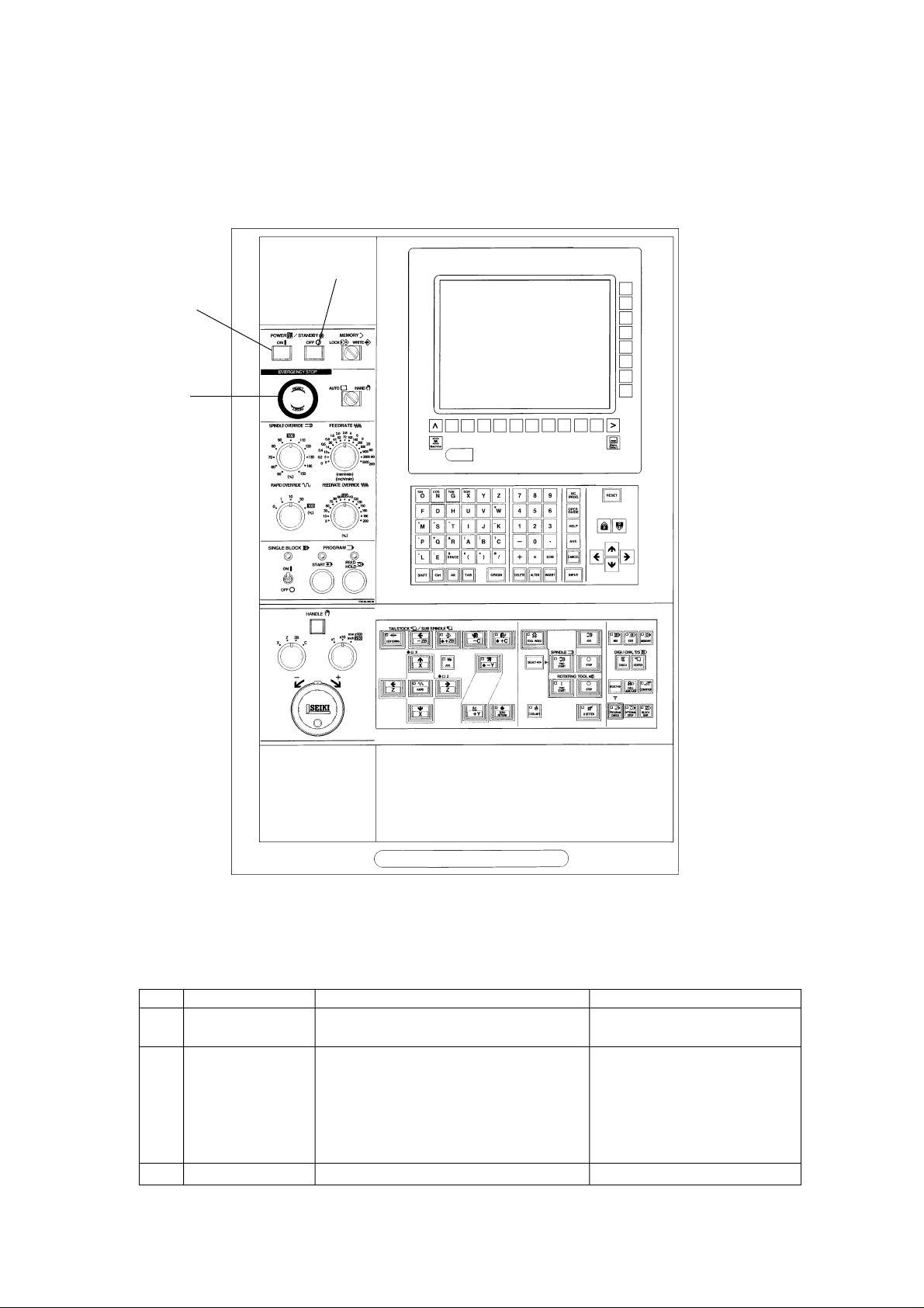
2. Explanation of Outline of Main and NC Operation Panel
2-1 Main Operation Panel
[3]
[1]
[2]
No. Name Function Remarks
[1] POWER ON/ The power of NC unit is ON./Make the The power ON lamp lights.
STANDBY machine condition ready to operate.
[2] EMERGENCY Make the machine condition impossible to Emergency stop is displayed on
STOP BUTTON operate. the upper left of the screen.
(However, the hydraulic pump does not
stopped.)
Stop a section under operation.
(Clear or discontinue the contents.)
[3] POWER OFF The power of NC unit is OFF.
1 - 2
Page 9
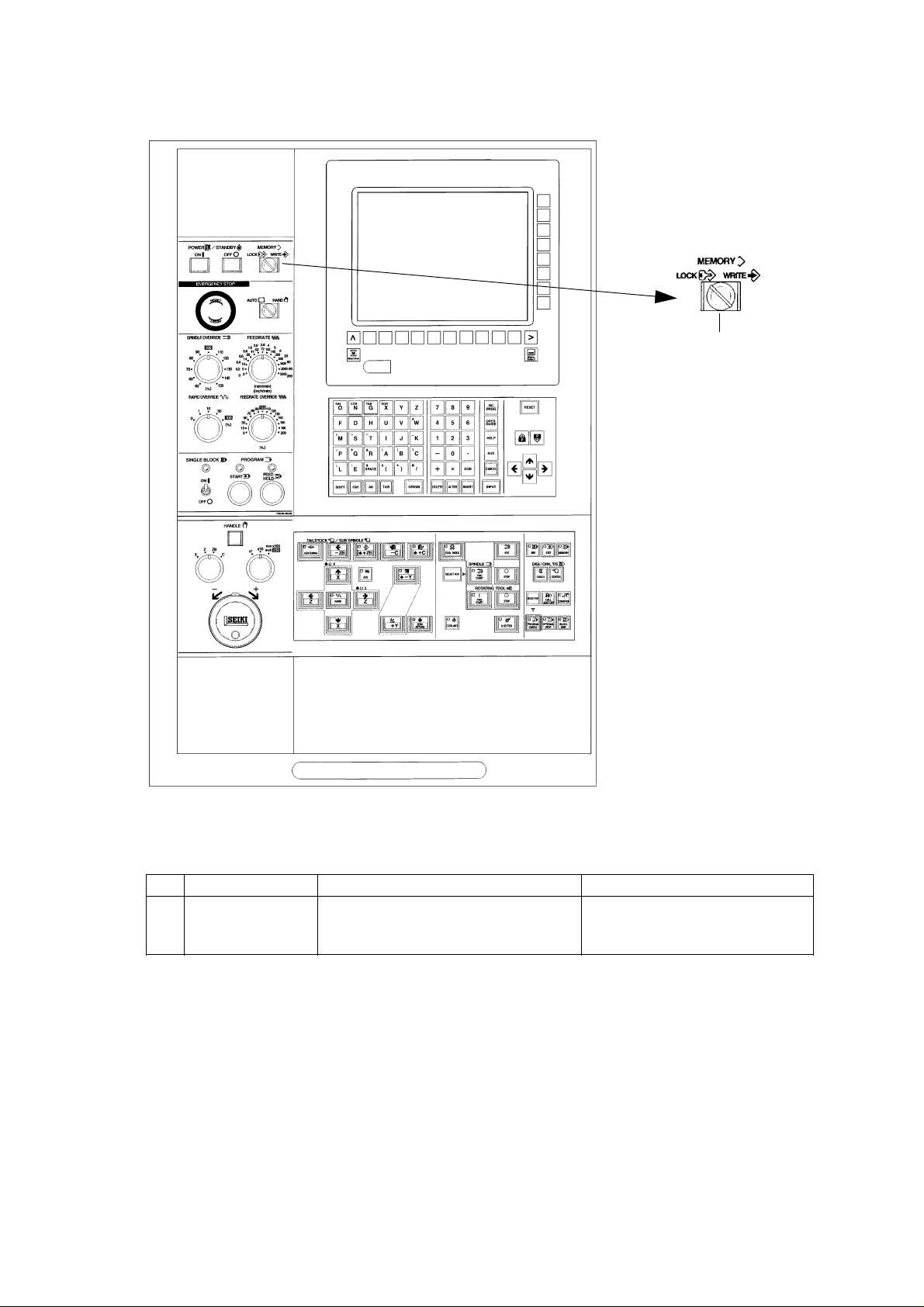
[1]
No. Name Function Remarks
[1] MEMORY Select the effective or ineffective of Set to the lock and pullout the key
editing operation of program and after edition.
parametor.
1 - 3
Page 10
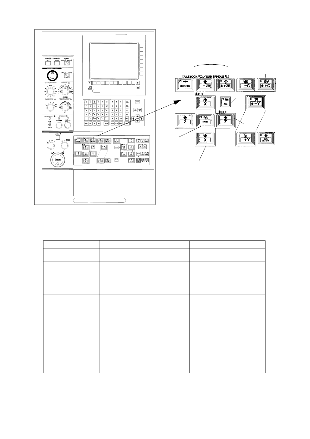
[2] [3] [4]
[1]
[5]
[6] [8]
[9]
No. Name Function Remarks
[1] ZERO RETURN Return to the reference point in the order At the time of power on, please be
KEY of X and Z axes. sure to perform a return to the
reference point.
[2] CENTER Advance the tailstock continuously. When the spindle is stopped.
FORWARD KEY
[3] CENTER JOG KEY Advance the tailstock while pressing. Effective in manual and memory
mode.
[4] CENTER Retract the tailstock while pressing. Effective in manual and memory
RETRACT KEY mode.
[5] SPINDLE SELECT Press this key simultaneously when
KEY forward or reverse the spindle.
[6] SPINDLE FWD The spindle rotates forward by pressing There are interlocks of the door
START KEY with the SPINDLE SELECT key and chuck and tailstock.
simultaneously when manual mode.
[7] SPINDLE JOG ON The spindle rotates while pressing. The function interlocked with
KEY tailstock.
[8] SPINDLE STOP The spindle stops when manual mode
KEY
[9] CALL LIGHT OFF Turn off the call light.
KEY
[7]
1 - 4
Page 11
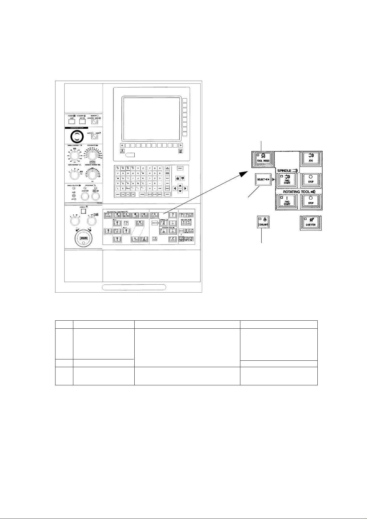
[2]
[1]
[3]
No. Name Function Remarks
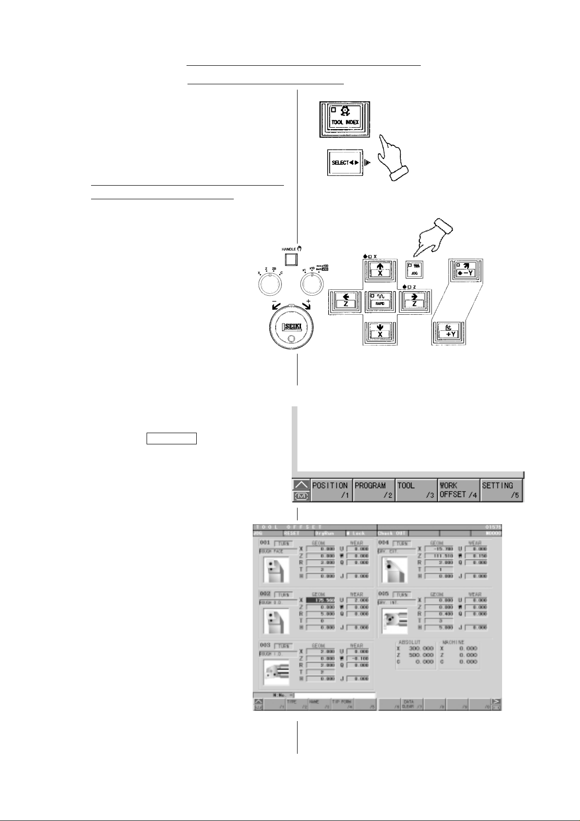
[1] TOOL INDEX START In the manual mode:
KEY By pressing this key and the SELECT key
simultaneously, the tool rest starts
rotation.
[2] SELECT KEY
[3] COOLANT MANUAL To direct coolant supply manually
KEY ON/OFF
1 - 5
Page 12
[6]
[5]
[4]
[1]
[3]
[2]
No. Name Function Remarks
[1] JOG KEY Select when executing the operation of Under m a n ua l mode.
the manual continuous feed.
[2] +X, -X KEY The manual continuous feed is available Set the feedrate by the feedrate
at the JOG mode. switch.
Move continuous in the selected direction When the +X key is kept pressing,
by pressing any one of +X or -X key. it is stopped at the machine
reference point.
[3] +Z, -Z KEY The manual continuous feed is available Set the feedrate by the feedrate
at the JOG mode. switch.
When the +Z key is kept pressing,
it is stopped at the machine
reference point.
[4] +C,-C KEY The manual continuous feed is available
at the JOG mode.
[5] +ZB,-ZB KEY The manual continuous feed is available
at the JOG mode.
[6] RAPID KEY Move by the rapid traverse with setting %
value of override while pressing under the
manual continuous feed.
1 - 6
Page 13
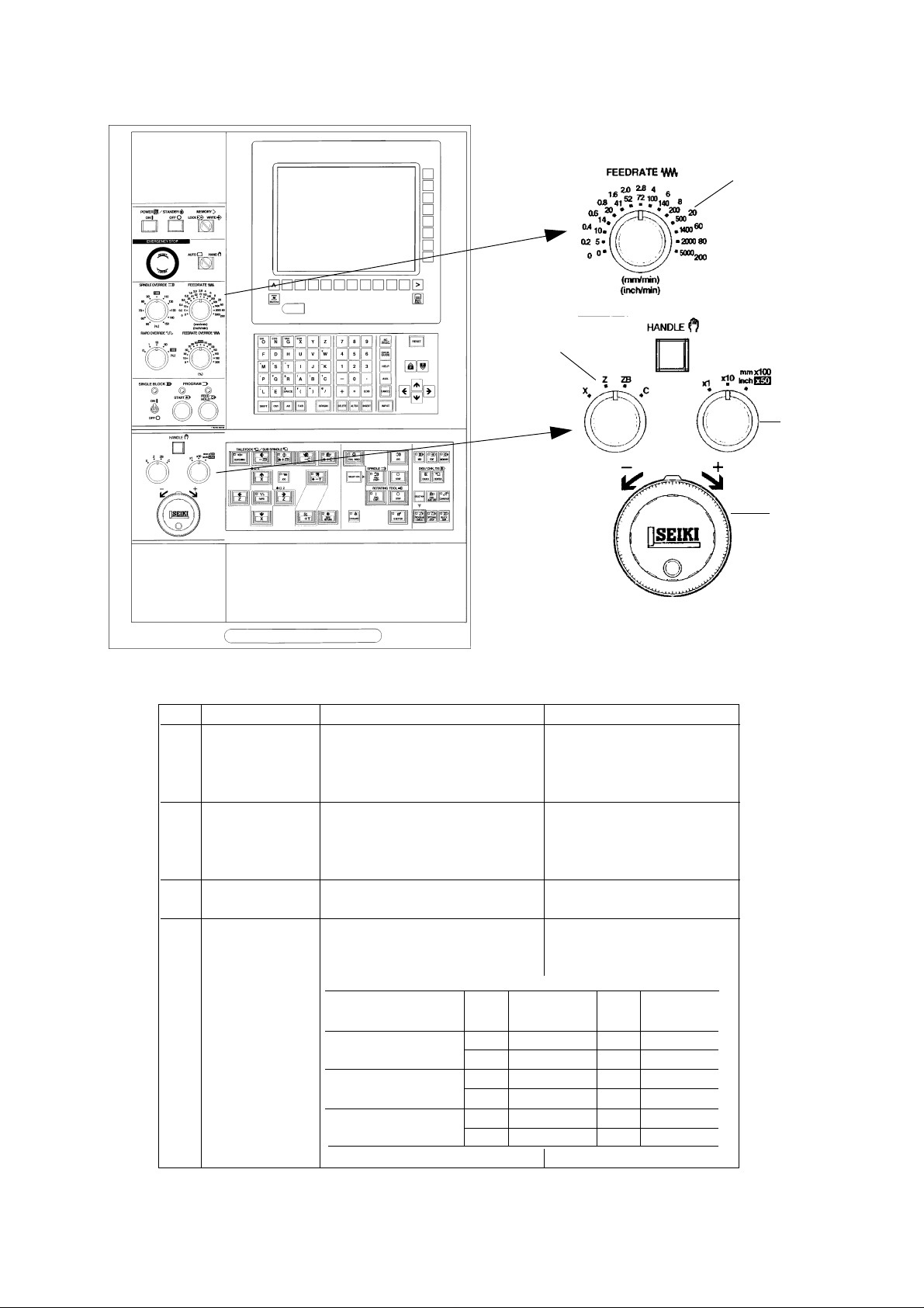
[1]
[3]
[4]
[2]
No. Name Function Remarks
[1] FEEDRATE Select the feedrate when 0~5000mm/min
SWITCH execution of the manual 15 steps
continuous feed or program check
operation (dry run).
[2] HANDLE Execute the handle feed (a fine 100div./ rev.
feed of the machine), when one of A feed amount per division is
the X, Z, ZB or C axes under feed according to the setting of
mod e. magnification [4].
[3] FEED AXIS KEY Select one of the X, Z, ZB or C Under manual mode.
when moving by the handle.
[4] HANDLE FEED Select an amount per division of
MAGNIFICA TION the handle.
CHANGE KEY
Feed magnification Axis Indication Axis Indication
key amount µ amount
1/1 X 1 ZB 1µ
Z 1 C 0.001°
10/1 X 1 0 ZB 10µ
Z 1 0 C 0.01°
100/1 X 100 ZB 100µ
Z 100 C 0.1°
1 - 7
Page 14
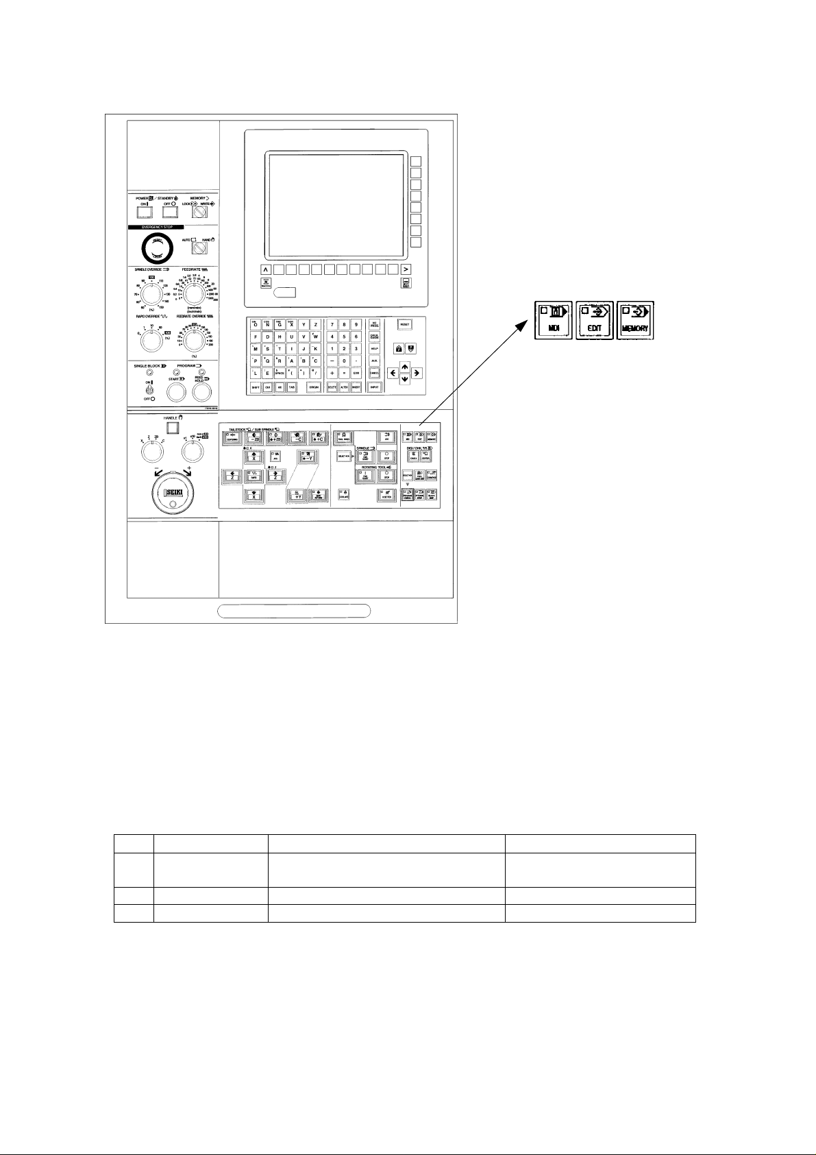
[1] [2] [3]
No. Name Function Remarks
[1] MDI Select when MDI input by the CRT Automatic mode
operation panel of NC unit.
[2] EDIT Select when editing program stored. Automatic mode
[3] MEMORY Select when execution of program stored. Automatic mode
1 - 8
Page 15
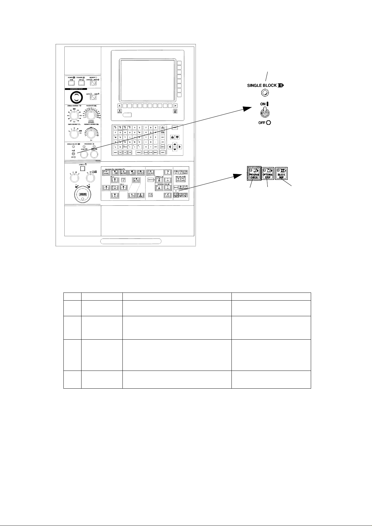
[2]
[1]
No. Name Function Remarks
[1] PROGRAM Make the stop condition of spindle and
CHECK coolant besides the dry run function.
[2] SINGLE Stop after execution of one block and
BLOCK move to the execution of next block by the
start key .
[3] OPTIONAL Program stops by the M01 on the
STOP program.
Press the program start key when start
again.
[4] BLOCK SKIP Skip a block with slash (/) code in the
program.
[3]
[4]
1 - 9
Page 16
[4]
[5] [3]
[1] [2]
No. Name Function Remarks
[1] PROGRAM ST ART Start automatic operation.
KEY (MDI, Memory)
[2] PROGRAM FEED Halts automatic operation. MST function is kept on while
HOLD KEY Feeding only decelerates and the work continues, and halts
stops. when completed.
[3] FEEDRATE Feed rate can be changed in the
OVERRIDE range of 0 to 200% under MDI or
SWITCH automatic operation.
[4] SPINDLE The spindle speed can be Ignores while thread cutting
OVERRIDE changed in the range of 50 to (G32, G92, G76)
SWITCH 150%
[5] RAPID OVERRIDE The rapid speed can be changed
in the range of 0 to 100%
1 - 10
Page 17
2-2 NC Operation Panel
1 - 11
Page 18
[3]
[2]
[4]
M
MACHINE
[16]
[7]
ON G XY Z 7 8 9
| ! % , - ¥
FDHUVW 4 5 6
< > “ { } _
MSTI JK 1 2 3 HELP
‘ & [ ] ?
PQRABC -0· AUX.
; : $ # * @
LE ( ) / += CANSEL
SP ACE EOB
NC
PROG.
OPER.
GUIDE
[15]
[6]
[5]
[10]
SELECT
RESET
[14]
NEMU
[17]
[1]
SHIFT
[8]
Ctrl Alt TAB
ORIGIN
[11]
DELETE
1 - 12
AL TER
[12]
INSERT INPUT
[13]
[9]
Page 19

NC Operation Key
No. Name Description
[1] RESET key
[2] Function keys
[3] Maintenance Menu Display key
[4] RETURN key
[5] AUX. key
[6] HELP key
[7] Address and Numerical keys
[8] SHIFT key
[9] INPUT key
Press this key when resetting the CNC unit in order to
reset an alarm, and so on.
When the function menu is displayed at the bottom of
the CRT, there are the keys to select the menu.
Pressing this key in the overall screen switches to the
maintenance menu.
Press this key when you want to return to the Overall
screen.
Press this key when you want to move the cursor of
the overall screen to another window .
Used to input the alphabet, numbers, etc.
There are some address keys which have 2 characters
marked on them. If you press the address key after the
SHIFT key, upper left character is input.
If the address or numerical key is pressed, it is input
into the key input buffer once, and then, displayed on
the CRT. Press the INPUT key when actually setting
the data input into the key input buffer.
[10] CANSEL key
[11] ORIGIN key
[12] DELETE, ALTER and INSERT
keys
[13] Cursor key
[14] Page key
[15] OPER. GUIDE
[16] MACHINE key
[17] MENU SELECT key
Press this key when deleting the characters or
symbols input into the key input buffer .
This key is used to clear the Plot screen.
Used to perform deletion, alteration and insertion in
editing the program.
There are 4 keys which are used to move the cursor
up/down and right/left.
There are 2 keys which are used to page in the
forward and backward directions.
Press this key when you want to display in the
Operation Guide screen.
In case of a multiple series machine, use this key to
switch the series to be displayed.
Pressing this key in the overall screen switches to the
menu to display a small screen.
1 - 13
Page 20

2-3 Chip Conveyor Operation Panel
1) Chip Conveyor Operation Panel
Chip Conveyor Operation
Panel Diagram
2) Function
No. Name Type Function
[1] FOWARD Push Button Forward switch is valid in manual mode only.
The action is kept on.
[2] REVERSE Push Button Reverse switch is valid in manual mode only.
Inching operation.
[3] STOP Push Button Stop switch is valid regardless of the mode.
[4] EMERGENCY STOP Mushroom Type Emergency stop switch is valid for stopping
both chip conveyor/main machine, regardless
of the mode.
[5] MAN/AUTO Switching In manual mode: Buttons [1] [2] are valid.
In auto mode: By command from the main
machine, forward operation is stopped.
Buttons [1] [2] are invalid. Do not switch
man/auto during operation.
[6] RUNNING Lamp Lamp lights while the chip conveyor is is in
operation.
1 - 14
Page 21
3. Procedure of Machine Operation
3-1 At the Time of Start
[1] Turn on the power source switch.
[2] Supply air pressure.
[3] Turn on the power switch of the power
control cabinet.
[4] Press the POWER/STANBY [ON] on the
left corner of themain control panel.
Caution
Main panel and NC unit is sealed type
construction and avoid a mixture of outer
air directly. Therefore, don’t keep open
the door long time of period during power
on.
Check on the display and that fan motors
heat exchanger are started.
[5] Once the Overall screen is displayed,
turn [EMERGENCY STOP] to the right to
unlock it.
[6] Press the POWER/STANBY [ON] on the
left corner of the main operation panel.
(Lamp lights.)
Check a setting pressure of hydraulic unit
2
is 3.5Mpa{35kgf/cm
[7] Move X and Z axes several times to
lubricate each slide way before starting
operation.
(Pay attention to avoid over travel.)
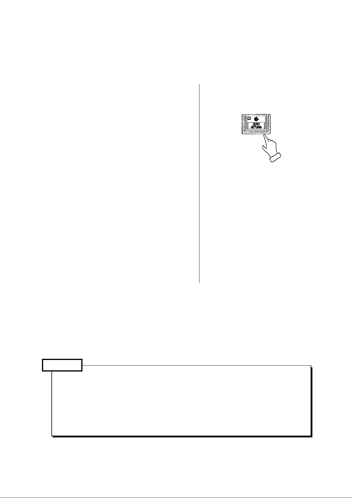
[8] Press the [ZERO RETURN] .
(Refer to “Procedure of zero return”)
This will return the turret head to the
machine zero point.
[9] Turn on the switch for chip conveyor.
}as fixed value.
Caution
Do not operate the machine with plenty of
chip in the trough of chip conveyor.
1 - 15
Page 22

3-2 Warming-up Operation of Spindle
Caution
It is important to keep status of bearing in good condition by lubrication, etc., to make
the spindle rotate normally. Sudden rotation of the spindle may cause sticking of the
bearings because of shortage of lubricating oil at the bearing section. To get the best
performance of the spindle function by correct operation, warming-up operation as
below-mentioned is necessary.
Warming-up operation for every starting (30 minutes)
[1] 10 minutes at 30% of the maximum spindle rotation
[2] 10 minutes at 50% of the maximum spindle rotation
[3] 10 minutes at 80% of the maximum spindle rotation
Conduct warming-up operation in the above order, [1], [2], [3]
1 - 16
Page 23
3-3 Procedure of Zero Return
This function is conveniently designed to return the turret head to the machine zero point in
order of the X- and Z-axis in single-touch operation.
Method 1 of zero return
[1] Make a mode to [JOG].
Move the X- and Z-axis about 100 mm in
the minus direction.
[2] Press the [ZERO RETURN] key.
If a single-touch zero point return
prohibited area alarm is issued, move the
X- and Z-axis until the alarm has
disappeared.
[3] Move a tool head to zero point by rapid
traverse (10% override). The tool head
stops at zero point and a confirmation
lamp of zero point of the axis turns on.
Return the X- and Z-axis to the zero point
in that order.
Method 2 of zero return
[1] Make a mode to [JOG].
[2] If the X and Z axes locate near the zero
point, move it opposite direction (Minus)
from zero point about 100mm.
[3] Press [X+] and [Z+] in that order to return
the X- and Z-axis to the zero point.
[4] Release a finger from the switch after the
confirmation lamp of zero point turned on.
Execute zero point return of each axis by the
operations above.
Caution
1. Execute zero return of axis one by one for safety.
(At first, do it from X-axis.)
2. Pay attention of interference with the tailstock at the time of zero return.
3. The turret head does not move when rapid traverse override is 0 %. Set it to 1 % or
10 %.
4. When rapid traverse override is 1 %, it moves at override of 1 %.
1 - 17
Page 24

3-4 At the End of Operation
[1] Clean up the machine.
Stop the chip conveyor after all chips
carried out from the conveyor.
[2] Confirm the machine stopped completely.
• Spindle rotation
• Program
• X and Z axes
• Coolant
• Chip conveyor
[3] Press the [EMERGENCY STOP] button
on the main operation panel.
[4] Press power [OFF] button at the main
operation panel and control power off.
[5] Turn off the power switch of the power
control cabinet.
[6] Cut out supply air pressure.
[7] Set the main power switch [OFF].
1 - 18
Page 25

4. Manual Operation
4-1 Feed of Each Axis
— In case of manual feed —
[1] Press the [JOG] for mode select push
button switch.
You may select the [HANDLE] either.
[2] Set the manual federate rotary switch to
suitable speed.
Move the machine to desired direction by
the manual feed direction push button
switch.
Take a finger off from the switch when
reach to the fixed position.
(The machine moves only when pressing
the switch.)
In case of a feed by the HANDLE, it can
be operated the same about it.
(Example of use)
• Warm up running
• In case of approach near the zero position.
• In case of cutting manually
• Setting work
1 - 19
Page 26

— In case of the handle feed —
[1] Select the axis by the axis push button
switch.
[2] Fine feed can be done by the manual
handle.
• When select 1/1: One division is
0.001mm
• When select 10/1: One division is
0.01mm
• When select 100/1: One division is
0.1mm
In case of the spindle indexing C axis, the
unit becomes a degree.
1 - 20
Page 27
4-2 Operating Method of Q-setter
A tool position compensating value can be get easily, since a tool position compensation is
inputted automatically by touching a tool tip to the Q-setter.
In case of the turret rotates, a cursor changes automatically due to a tool face number
correspond an offset number.
[1] Confirm the zero return condition of the X
and Z axes.
If confirmation lamp is not lit, execute
manual zero return.
[2] Make a mode to manual mode [HANDLE]
or [JOG].
[3] Pull out the Q setter
A screen changes to the offset screen
automatically and display the “Q-setter”
and inform a ready of complete condition
of preparation.
Zero return lamp turns on
[4] Call a tool compensation required.
Press the [TOOL INDEX] and
[SELECT] at the same time.
1 - 21
Page 28
[5] Confirm a tool face on the turret and
offset number.
A tool face selected at this moment is
recognized by a cursor position.
[6] Approach a tool tip to the tool setter
TOOL (OFFSET)
Sharp Wears
01
X 1.000 U 0.000
Z 3.000 W 0.000
R 0.000 Q 0.000
T3
H 0.000 J 0.000
(Q setter)
Procedure (1) Handle magnification key
100/1
(2) Rotate a handle to minus
direction.
[7] Position a tool tip to the center of the
sensor by [HANDLE].
[8] When a tool tip touches the sensor by
JOG mode, a compensating value is
inputted automatically. At this time, the
feed rate is fixed, disabling speed
selection.
Caution
If it is executed by operating the
[HANDLE], the accuracy will not be
stabilized. (Reason: When having the tool
nose touch the Q setter, the accuracy is
stabilized by having it touched at a
constant speed.)
For X Azis
For Z Azis
Sensor Base
TOOL (OFFSET)
Sharp Wears
01
X 35.000 U 0.000
Z 0.125 W 0.000
R 0.000 Q 0.000
T3
H 0.000 J 0.000
When a tool tip touch to the sensor,
sound beep and stop the tool head and
input a compensation value.
The wear offset amount of the axis
touched by the tool nose is made 0
(zero).
1 - 22
Page 29
[9] Execute a tool tip measurement by touching a tool tip to the sensor twice or so.
Confirm a tool compensation
amount on the screen.
[10] Retract a tool tip from the sensor to safety zone by
[HANDLE] mode. A safety zone is a position which is not
interfered a tool and sensor even if the turret rotates.
When retracting the cutting edge in the [HANDLE]
mode from the beginning, retract it slowly up to about
1 mm. If retracted abruptly in the [HANDLE] mode,
the cutting edge direction may be misconceive,
disabling an entry of a correct compensation value.
[11] Get a compensation amount for the other tool in turn as the same method.
OTHERS
Reference In case of thread cutting tool
In case of thread cutting tool, a tool compensation value of Z value is obtained by the side
of insert as described by Fig. 1 and 2, effective length of thread becomes short by “Width
T” due to position of cutting edge is different. Therefore, get a tool compensation amount
by the Q setter as Fig. 1 then execute incremental compensation input to minus side (In
case of Fig. 2, plus side), so correct effective length of thread can be get as Fig. 3.
The incremental amount you can input at a time is up to 1mm. If it exceeds 1mm, divide the
input into several times, with the amount less than 1mm each time.
Fig.1(Right hand thread) Fig.2(Left hand thread) Fig.3
1 - 23
Page 30
How to get a tool compensating amount for a tool
tip may not be touch the Q-setter
A work coordinate system setting should be
done before executing this operation.
A correct compensating amount can not be
found without a work shift operation.
“How to get a tool compensating amount
1.
for a longitudinal direction (Z)”
[1] Call a tool by index the turret.
Select the mode switch either the
[HANDLE] or [JOG].
[2] Call the tool offset screen and
confirm a tool compensating amount
(Z) is zero. Set zero if it is not zero.
Press the [TOOL INDEX]
and [SELECT] at the same
time.
Press F3/TOOL .
Example: In case of T0200
Set the tool (offset) No. 02.
1 - 24
Page 31

[3] Touch a tool to the end face of
workpiece.
It the end face is a black skin,
execute it after cutting a black skin.
Caution
Reduce a magnification of the handle to avoid a breakage of tool and apply a paper
between a workpiece and tool.
[4] watch a position “Z” of tool position.
3.0
Removal amount L
Machining reference point
Paper
1 - 25
Page 32

O Tool compensating amount
A value subtract a removal amount (L) from a tool position (Z).
Toll compensating amount (Z) = Tool position (Z) - Removal amount (L)
Example: Tool compensating amount = (150.0) - (3.0) = 147.0
147.0 is a tool compensating amount of the longitudinal direction.
[5] Input a tool compensating amount.
Z147.INPUT
Caution
Execute it with confirmation, if the setting of shift amount (machining original position) of
Z-axis work coordinate system is correct or not before this
Besides, a tool tip position should be same as a removal amount when a tool touches
end face is has touched the Q-setter.
1 - 26
Page 33

How to get a tool compensating amount for a tool
tip may not be touched the Q-setter.
“How to get a tool compensating amount
2.
for a radial direction (X) ”
It is the same as longitudinal direction
from the item [1] to [3]. Refer it to them.
[4] Cut a workpiece.
or
Feed level
Caution
To avoid a defective parts, it is enough a skin cut. Never move on the X-axis after OD
turning.
[5] Watch a position “X” of tool
position.
Example: In case of T0300
Set the tool (offset)
No.03.
1 - 27
Page 34

O Tool compensating amount
A value subtract a diameter of workpiece (φD) from a tool position (X).
Toll compensating amount (X) = Tool position (X)
- machined diameter of workpiece (φD)
Example: Tool compensating amount = (65.0) - (63.0) = 2.0
2.0 is a tool compensating amount of the diameter direction.
[6] Input a tool compensating amount.
X2.
INPUT
1 - 28
Page 35

4-3 Q-setter Repeat Function
Through a simple operation, you can repeatedly perform measurement on tip changing of a tool
which has already been subject to measurement in Q setter.
4-3-1 Procedures
Push F6/Q-SETTER REPEAT on Tool (Compensation) page, Window page for Q setter
[1]
repeat is displayed.
[2] Set Feed mode.
[3] Changing a tip, perform indexing of the turret to a measurement position. At this time both
the cursor inside Turret State on the left side of the page and the compensation data at the
top right-hand corner of the page change as linking to the turret face.
[4] Bring out the Q setter arm.
[5]
Push F4/START .
If the tool has been already subject to measurement in Q setter (with the data already
existing in the measurement position on the page), measurement by Q setter repeat is
started. When the tool touches the sensor, a measured value is written in compensation
data. The touch mark is displayed on the picture indicating a measurement position.
If measurement has not yet been performed in Q setter, alarm takes place.
Fig. 7-2 Q Setter Repeat Screen
1 - 29
Page 36

4-3-2 Function Key
F4/ Repeat Measurement Start :
“OK? Y- Yes N- No” message appears. With Y ,
measurement starts.
F5/ Repeat Measurement Halt : Measurement operation is stopped.
F6/ Function Return : Screen display returns to Tool Compensation.
F7/ Data Delete : On appearance of a window, select either “One Meas. Spot”
or “Whole Meas. Spot” and push INPUT . “OK? Y- Yes,
N- No” message appears. With Y , the measurement
spots are deleted.
4-3-3 Working
The working patterns, as shown in Fig. 7-3(c) can be divided into 8 kinds according to the
virtual nose points.
When Virtual Point 1, 2, 3, or 4 being assigned, both X and Z axes are subject to measurement.
The order for measurement, in that case, is always Z to X axis.
When Virtual Point 0, 5, 6, 7, 8, or 9 being assigned, X or Z axis alone is subject to
measurement. In this case, for compensation of the axis not being measured, compensation
needs to be input manually beforehand. As for virtual nose points of tools, see Fig. 7-3(a).
8
4
5
8
3
7
9
0
1
6
2
Fig. 7-3(a) Virtual Nose Points of Tools
1 - 30
Page 37

The following example describes the case when the virtual nose point is 1:(See Fig. 7-3(b))
[1] Shifted in rapid traverse from Start Point (PO) to Point 1 (PO).
[2] Shifted in rapid traverse from P1 to P2.
[3] Shifted in rapid traverse from P2 to P3.
[4] Shifted in feed speed from P3 to the end position (P4) to be touched.
[5] Shifted in feed speed from the point where touching and stopping have taken place.
[6] Shifted from P5 to P6 in rapid traverse.
[7] Shifted from P6 to P7 in rapid traverse.
[8] Shifted in feed speed from P7 to the end position (P8) to be touched.
[9] Shifted in feed speed from the touch-and-stop position to P9.
[10] Shifted from P9 to P10 in rapid traverse.
[11] Shifted from P10 to the start point (P11) in rapid traverse.
Machine origin
MD62200[12] MD62200[11]
-X
P4
P8
P7
1
+X
P9
MD62200[12]
P3
P5
P6
P2
X
Z
+Z
-Z
MD62200[6]
MD62200[13]
MD62200[14]
MD62200[7]
MD62200[5]
MD62200[4]
P11
P0
(Start
Point)
P10
P1
Fig. 7-3(b) Working with Virtual Nose Point 1
1 - 31
Page 38

3
8
2
4
6
7
0
9
MD62200[12]
1
5
MD62200[13] MD62200[13]
MD62200[14] MD62200[14]
Fig. 7-3(c) Working PatternsFig.
1 - 32
Page 39

Caution
1. When a tool has been changed, be sure to manually apply it to Q setter.
2. Apply it to Q setter only once.
3. Approaching, in rapid traverse, from the sensor to the place just before the clearance
amount on approach, touch the sensor in the feed rate (mm/min).
4. Single block is held valid while in measurement operation.
(Re-started with F4/REPEAT START .)
5. When the measurement start point can touch the sensor, alarm takes place.
6. When the sensor has not been touched in measurement, alarm takes place after operation
is over.
7. Threading tools, tip changing type drills, end mills, and other tools which are similar to
these cannot be subject to measurement.
8. The measurement start point is any one position free from danger or touching the sensor.
9. When, in some operation patterns, an interference exists with a work, remove the work
from the chuck.
10. When a large difference exists between the Q setter measurement and the work
measurement dimension, adjust Q setter position on Maintenance page.
11. When the machine is provided with the Y-axis, it must be in the following conditions when
starting Q-setter repeat.
• The Y-axis is at the origin. (The ORIGIN lamp is ON)
• The tool offset amount for the Y-axis is 0. (Both shape and Wear are 0)
12. The measuring spots are deleted in the following cases:
• When Data Delete on the screen is effectuated.
• When shape data for tool compensation volume and nose T have been input.
4-3-4 Relevant Parameters
No. 8003, #0=0 Does not check the door close in the Q setter repeat.
=1 Checks the door close in the Q setter repeat.
#1=0 Measurement time of the Q setter repeat is 1 time.
=1 Measurement times of the Q setter repeat are 3 times.
#2=0 The touch signal check in the Q setter repeat is valid.
=1 The touch signal check in the Q setter repeat is invalid.
#3=0 Measurement of a rotation tool in the Q setter repeat is not possible.
=1 Measurement of a rotation tool in the Q setter repeat is possible.
1 - 33
Page 40

#4=0 The Q setter interlock is invalid.
=1 The Q setter interlock is valid.
#7=0 The Q setter barrier check is invalid.
=1 The Q setter barrier check is valid.
MD62200[4] Q setter contact area + Side coordinate value X (mm) (set by the radius)
MD62200[5] Q setter contact area + Side coordinate value Z (mm)
MD62200[6] Q setter contact area - Side coordinate value X (mm) (set by the radius)
MD62200[7] Q setter contact area - Side coordinate value Z (mm)
MD62200[11] Thrusting amount of the Q setter repeat (mm)
MD62200[12] Clearance amount on approaching for Q setter repeat (mm)
MD62200[13] Clearance amount for right-handed machine tool for Q setter repeat (mm)
MD62200[14] Clearance amount for left-handed machine tool for Q setter repeat (mm)
MD62210[0] The feed rate when having the Q setter repeat touch (mm/min).
MD62210[1] The return rate from the position the Q setter repeat touched (mm/min).
4-3-5 Relevant Alarms
No.67100 An error occurred in the Q setter repeat.
No.67124 No measurement has been performed in Q setter.
No.67138 The touch signal was not entered in the Q setter repeat.
No.67139 Measurement start point of Q setter repeat is not correct.
No.67149 Cannot measure the rotary tool with Q-setter repeat.
1 - 34
Page 41

4-4 How to Shape Soft Jaw
In order to manufacture precision products of high commercial value, without flaws on
workpiece, a soft jaw is formed. By forming a soft jaw matching with the chuck, cutting work
can be performed safely and steadily thus the accuracy of processed goods will improve. For
shaping a soft jaw, there are two methods; one is to utilize the simple soft jaw forming function,
the other is to form one by manual operation.
4-4-1 Simple Jaw Edge Forming Function
(1) Outline
With “Edge shape” “Working Conditions” being input according to the guidance on the
page and the start button being pushed, raw edge machining starts.
(2) Operation
[1] Index the tool used for raw edge forming to the machining position.
[2]
Pushing F6/JAW on the page of the work coordinate system
(General → F4/WORK OFFSET ), display Window page for raw edge forming.
[3]
Select either outer jaw or inner jaw forming by using F4/OUTER JAW or F5/INNER JAW .
[4] Prepare the section where a core bar is fitted and mount it properly.
[5] Input an edge configuration and working conditions.
[6] Turning the spindle in Manual mode, shift the tool to the edge position.
With F3/JAW END SURFACE pushed, “Jaw end surface position setting? Y-Yes/N-No”
is displayed. With Y , set the jaw end position.
[7]
Pushing F9/SHAPE CHECK in MDI mode, check the shape of a working program. If not
in MDI mode, “Set MDI mode” message is displayed. While in shape checking, Dry-Run
and Machine Lock ON state are held effective. The operation panel lamps, however, do
not lit up. Also, no MST code is output.
The coordinate system (tip position) is brought to presetting on completion of shape
checking or by resetting while in checking.
[8] Perform zero returning as paying attention not to cause interference.
[9] Pushing the start button in MDI mode, execute a working program of raw edge forming.
Fig. 8-2(a) Jaw Edge Forming (Outer Jaw)
1 - 35
Page 42

Fig. 8-2(b) Jaw Edge Forming (Inter Jaw)
(3) Function Key
F2/SET UP : The Setup window appears and allows you to specify the spindle
speed and turret indexing.
F3/JAW END SURFAC : “Jaw End Surface Position Setting? Y-Yes/N-No” message is
displayed. Set with Y .
The Z coordinate value of the (soft jaw) tool nose position is
cleared to 0. (The Z coordinate value for the relative coordinate
system.)
F4/OUTER JAW : Outer Jaw Forming page is selected.
F5/INNER JAW : Inner Jaw Forming page is selected.
F6/EXIT : Work Coordinate System page is returned.
F7/DATA CLEAR : “Edge Configuration and Working Condition Erased? Y-Yes/N-No”
message appears. Select Y to clear.
F8/RESET : Soft jaw forming is ended. Push this to return to normal work.
The jaw end surface setting position is cleared.
F9/SHAPE CHECK : A shape of a working program is drawn.
F0/JAW CONTOUR DRAWING: You can turn, enlarge and contract the picture of the jaw
contour.
1 - 36
Page 43

(4) Jaw Configuration And Machining Conditions
The meaning of each symbol of the jaw shape is as follows:
A: I.D./O.D of the first step.
B: Depth of the first step
C: Diameter of the ring (core metal) used
D: I.D./O.D of the second step (If value 0 is set, the shape of jaw formed is a single step
jaw.)
E: Depth of the second step (If value 0 is set, the shape of jaw formed is a single step
jaw.)
T: Taper amount of the gripping portion
F: Necking depth
G: The maximum amount of cutting margin (If value 0 is set, cutting proceeds to Z
direction in rough cutting (See Note 1). If value larger than 0 is set, copy cutting is
performed in rough cutting (See Note 1))
I: Setting of necking width (relieving width)
J: Bolt position 1
K: Input the amount of the jaw protruding from the chuck diameter with +/- sign.
(based on the chuck diameter)
Cutting speed, Revolution: The condition relevant to spindle revolution. Input appropriate
values either in cutting speed or revolution.
Feed speed: The feed speed for rough an finish cutting.
Cut-in amount: Cut-in amount in the rough cutting.
The cut-in amount in the X axis direction, when rough-cutting is performed
in the Z direction.
The cut-in amounts in the X and Z axis directions, when performing copy
cutting.
If value 0 is set, will perform finish cutting only.
Finish margin: If value 0 is set, will perform rough cutting only.
Chuck O.D.
Soft jaw I.D.
Soft jaw O.D.
(Note 1)
The dimension data necessary for jaw locus drawing.
}
These data have no direct connection with the machine action.
Z direction cutting Z direction cutting
1 - 37
Page 44

Caution
1. Before starting soft jaw forming, make jaw end face position setting. A warning is
issued, If shape check or soft jaw forming is executing without making the end face
position setting.
2. Clamp the maximum spindle revolution during the soft jaw forming with the parameter
setting value.
3. Attention should be paid to the tool tip shape, when executing copy cutting and
necking processing.
4. The maximum value of the margin (G) is the value where the margin is considered to
be uniform both directions of diameter and lengthwise. When the margin in two
directions are different, the larger value should be taken as the maximum value of the
margin for the setting.
5. Use decimal point, for inputting the value of dimensions.
6. When attaching a jaw, make sure that the jaw does not protrude beyond the outside
diameter of the chuck.
7. For jaws, always use the standard soft jaw.
8. When processing a thin workpiece, chucking pressure may be lowered for avoiding
deformation of the workpiece, In such cases, take care not to set the spindle revolution
speed too high.
• See the drawing
at right for the
forming shape.
0.05
Cut with taper of abt.
30
20 or more
Reference surface
Reference surface
The comer must be chamfered.
1 - 38
Page 45

(5) Relevant Parameters
(GUD) (Reference Values)
2075 Feed rate magnification in unload cutting of soft jaw forming
2074 Max. spindle rpm of soft jaw forming (1000rpm)
2071 Approach amount on finishing in soft jaw forming (10.000mm)
2073 Relieving amount of soft jaw forming (2.000mm)
2072 Clearance amount of soft jaw forming
(6) Relevant Alarms
No. 66270 Soft Jaw Forming Error
The detail of the alarm can be known by the numeral subsequent to # mark, the meaning
of which is as per list below.
#001 A 0 (A: 1st step inside/outside dia.)
#002 B 0 (B: 1st step depth)
#003 C 0 (C: Mandrel diameter used)
#004 D 0 (D: 2nd step inside/outside dia.)
#005 E 0 (E: 2nd step depth)
#006 T < 0 (T: Taper amount at holding part)
#007 F < 0 (F: Necking depth)
#008 G < 0 (G: Maximum value of cut margin)
#009 H < 0 (H: Chamfering amount)
#010 I < 0 (I: Necking width)
#01 1 C A (Mandrel dia. 1st step I/D)
#012 C A (Mandrel dia. 1st step O/D)
#013 D A (2nd step 1st step I/D)
#014 D A (2nd step 1st step O/D)
#015 C D (Mandrel dia. 2nd step I/D)
#016 C D (Mandrel dia. 2nd step O/D)
#017 B E (1st step 2nd step depth)
#018 Chamfering is too large.
<
=
<
=
<
=
<
=
<
=
>
=
<
=
>
=
<
=
>
=
<
=
>
=
>
=
<
=
>
=
<
=
>
=
<
=
>
=
#019 Necking width is too large.
#020 Interferes with bolt .
#101 Cutting speed (roughing) 0
#102 Cutting speed (finishing) 0
#103 Feed speed (roughing) 0
#104 Feed speed (finishing) 0
#105 Cut-in 0
<
=
<
=
<
=
<
=
<
=
1 - 39
Page 46

#106 Finish margin < 0
#107 Chuck outside dia. < 0
#108 Bolt barrier: Jaw bolt hole pitch < 0
#109 Bolt barrier: Bolt hole center < 0
#110 Bolt barrier: Counter bore dia. < 0
#11 1 Approach amount < 0
#112 Clearance amount < 0
#1 13 Relieving amount < 0
#114 Spindle clamp revolution < 0
#901 Jaw form is not decided.
#902 St art from screen other than that for soft jaw forming.
1 - 40
Page 47

4-4-2 Soft jaw forming by manual operation
Steps Operation method Movement / Display
1 As shown figures in the
right, insert a ring (core
metal) on the front side
of a jaw. Adjust chuck
pressure to the same
Not to be protruded beyond
outside diameter of chuck
value of the actual
operation.
Chuck
Soft jaw
Portion to be removed
Ring
2 Obtain tool
compensation
amount of the tool used
for soft jaw
forming.(Refer Q-setter
operation method)
3 Move the too l rest, and
apply the soft jaw
forming tool to the soft
jaw.
Have the spindle rotate
in advance.
This operation allows you to accurately cut an inner
diameter dimension, viewing the “Position” screen, without
using a measuring instrument.
Soft jaw
Chuck
Ring
1 - 41
Page 48

Steps Operation method Movement / Display
4 Set “W” of relative
coordinates at 0.
(1)Press the key
F1/POSITION
Then, screen displays as
shown in the right
column.
(2)Press
F7/ZERO-SET
(3)Press
F2/W ZERO-SET
Then, the value of W
becomes 0.
1 - 42
Page 49

Steps Operation method Movement / Display
Scrape the jaw by
[HANDLE] operation, or in
the [JOG] mode.
• For this process:
Recommend separate
stages of course and
finish processings, as it
improves accuracy of the
cutting.
• Accuracy improves by
cutting the portion
chucking the ring beforehand.
• When soft jaw is reattached, make adjust
cutting for maintaining
chucking accuracy.
5.0 Current depth of Claw
Core metal
Diameter
Direct of cutting
1 - 43
Page 50

4-5 Manual Type Tailstock
Operating method of Tailstock and items for attention
• Retreat the tailstock to the back end on the base, when the center is not used for chuck
work and others.
• Do not use fixed center for the tailstock.
Procedures for tailstock operation
[1] Set the oil pressure or air pressure of
tailstock.
(Refer to Specifications Manual
“Tailstock pressure - Thrust Diagram”.)
[2] Chuck the work
[3] Stop the tail stock forward side of the
retreat end by forwarding inching
operation.
[4] Press the forward key to have the
tailstock moved forward.
[5] After the position is taken as above,
first remove the pins for traversing,
then tighten 2 fixing bolts.
Work being chucked
Tail stock moved forward
Chuking being readjusted
Foot switch
Application method of tailstock
1 - 44
Page 51

Re: One-touch Tailstock
<<Operation>>
1) Manual key
Forward key Pressing this key, the tailstock moves forward until the forward end.
When it comes into contact with the work, the hydraulic power works.
(To suspend the forward move, press the backward key. While
pressing the SELECT key, high-speed forward movement will
continue.)
Inching key While this key is kept pressed, the tailstock moves on forward.
Even when it presses the workpiece, the hydraulic power does not
work. (While pressing the SELECT key, high-speed forward
movement will continue.)
Backward key While this key is kept pressed, the tailstock moves backward.
(High-speed)
2) M Function
M25 (Tailstock low speed forward)
Moves forward to the forward end with low speed. When the tailstock presses the
workpiece, hydraulic power works and the action completes. When the action does
not complete within the time of the timer setting, an alarm is issued.
M26 (Tailstock high speed backward)
Moves backward with high speed until the designated time set by the timer setting
table expires, thereby the action completes.
M27 (Tailstock high speed forward)
Moves forward with high-speed until the designated time set by the timer setting table
expires, thereby the action completes. In high speed forward command, do not let the
tailstock come into contact with the workpiece.
M28 (Tailstock high speed return to the stroke end)
Moves backward to the stroke end, thereby action completes.
1 - 45
Page 52

5. Operation by Manual Data Input (MDI)
5-1 Program input by MDI
A MDI program can be executed by the
following operation.
[1] Select [MDI] mode on the operation panel
of the machine.
Press the > key.
[2]
[3] Key in a MDI program by the address and
the data key.
Example: When the spindle rotates 800
-1
.
min
1 - 46
Page 53

[4] When the INSERT key is pressed, a
commanded value moves upper section
of the screen.
[5] A command executes when pressing the
PROGRAM [START] key.
1 If wrong key are inputted by
mistake, key in again after pressing
the CANCEL key required number.
2 When a mistake is found on an
inputted command, release a
command by pressing the
RESET key.
Caution
Pay full attention to the safety, since the machine moves.
1 - 47
Page 54

5-2 Edition of MDI program
An inputted MDI program can be edited the
same as a part program stored in the
memory.
1. The cursor moves back or forth at a MDI
program by a block unit when the up and
down CURSOR key is pressed.
2. The cursor moves back or forth by a word
unit when the left and right
CURSOR key is pressed.
3. A MDI program moves back or forth by a
page unit when the PAGE key is
pressed.
4. Insert a data after the current position of
cursor by the INSERT key.
5. Alter a word, the cursor located currently,
to the inputted one by the
ALTER key.
6. A word, the cursor located currently,
deletes by the DELETE key.
7. A MDI buffer is cleared by the
RESET key. Key in the command value
again.
Caution
1. Editing is not available while
executing a MDI program,
however, it is possible when a
condition of the single block stop.
Execute the cycle start as it is,
after editing is finished.
2. In this case, please note that
regardless of the cursor position,
the program starts running from
the beginning.
1 - 48
Page 55

5-3 Operation of MDI program
1. Keep a mode of operation panel of the
machine a MDI, execute an inputted MDI
program by pressing the
[START] button.
Caution
Put the cursor at the head of the program,
because it executes from the current
position of the cursor.
2. When a MDI program executes
sequentially, the cursor moves at the
head of the block currently executing.
3. The MDI program is deleted after an
operation of MDI program is completed.
1 - 49
Page 56

6. Registration of Program
There are following two methods to register a program into the NC unit.
1. Registration from an external input device
2. Manual registration by the address/numeral keys
6-1 Registration from an external device
[1] Connect an input device RS-232-C
terminal and make a possible condition of
transmission.
[2] Set a mode to [EDIT].
[3] Set the memory key to [WRITE].
[4]
Press the F8/IN/OUT key.
Aright sketch is displayed.
Press the F1/INPUT key.
[5]
• Start reading from the first EOB of the NC program and continue until the % code.
• The program No. is registered the 0 No. registered in the input device.
• Display at the program No. list after completion of reading.
• At the time of input, the ISO/EIA information is recognized automatically.
Note) If the program No. already registered is inputted, it becomes an alarm condition. The
program numbers in the 8000s or 9000s are to be enabled or disabled in the Setting
screen. Confirm their setting prior to inputting/outputting them.(See Setting)
1 - 50
Page 57

6-2 Manual registration by the address/numeral keys
[1] Set a mode [EDIT].
[2] Set the memory key to [WRITE].
Press the F2/PRGRM key.
[3]
[4] Key in a desired program No. and press
the INSERT key.
Example:
[5] Set the cursor to ; by the cursor key.
1 - 51
Page 58

[6] Input a program according to the order of
the NC program.
Example:
Data>G28 U0
The EOB key must be inputted at
•
the end of one block.
• Press the CANCEL key when the
data which has inputted want to be
deleted.
A word deletes one by one.
Press the > key and return to the initial
[7]
screen after input of all program is
completed.
G 2 8 U 0
EOB INSERT
1 - 52
Page 59

7. Program No. Search
There are following two methods to search a program.
1. Search by key in a program No.
2. Search to utilize the program list.
7-1 Search by key in a program No.
[1] Set a mode to the [MEMORY] or [EDIT].
[2] Set the memory key to [WRITE].
[3]
Press the F2/PRGRM key.
[4] key in the program No. to be searched
and press the
Example: O 1 2 3 4
Calling up program is displayed.
key.
O 1 2 3 4
1 - 53
Page 60

7-2 Search to utilize the program list.
[1] Set a mode to the [MEMORY] or [EDIT].
[2] Set the memory key to [WRITE].
Press the F2/PRGRM key.
[3]
Press the F7/PROGRAM LIST key.
[4]
[5] Set the cursor to the program No. to be
searched by the cursor key and press
INPUT key.
Calling up program is displayed.
1 - 54
Page 61

8. Edition of Program
The keys to edit a program are as follows;
INSERT : Insert a content of key input after the cursor.
ALTER : Alter a content of key input at a section of the cursor.
DELETE : Delete a section of the cursor.
Use it deletion of program as well.
8-1 Preparation in Advance at the Time of the Edition of Program.
To edit a program, the following conditions
should be made.
[1] Set a mode [EDIT].
[2] Set the memory key to [WRITE].
Press the F2/PRGRM key.
[3]
1 - 55
Page 62

8-2 Search of Word
A word can be searched by the following
method.
1) A method by means of the page and
cursor keys.
[1] Press the page key and display the
page to be edited.
[2] Press the cursor key and move the
cursor to the word to be edited.
•The cursor moves at a block unit by
the
•The cursor moves at a word unit by
the keys.
2) A method by means of word or address
search.
Since a message is displayed as “Not
found” if it is not found, try it again.
keys.
[1] Word search, No. search
Key in the address and numerals to
be searched and press
Example: M08
key.
M 0 8
When searching a section above the
current position of cursor, press the
key
1 - 56
Page 63

[2] Block search
Check a word in a block and search
a block which contains a relevant
word only .
Key in all address and numerals of
one block then press EOB and
key.
Example: When searching a block of
G02 X130.0 Z120.0 I30.0 F0.5
Note)
The EOB should be inputted at the
end of a block.
G 0 2 X 1
3 0 . 0 Z
1 2 0 . 0
I 3 0 . 0
F 0 . 5
EOB
1 - 57
Page 64

8-3 Edition of Program
(1) Insertion of word, block
New word is inserted just after the word
currently located the cursor.
[1] Designate a word immediately
before a section to be inserted.
[2] Key in a new data to be inserted then
press the INSERT key.
Example: When inserting X100.0 after
G00
After insertion
X 1 0 0 .
0 INSERT
[3] When inserting one block, key in
data of one block and press EOB
and INSERT key.
1 - 58
Page 65

(2) Alteration of word
Alter a word, the cursor located currently,
to the new word.
Alteration is done by a word unit.
[1] Set the cursor to the word to be
altered.
[2] Key in the new word then press the
ALTER key.
Example: Alter S1500 to S2000.
S 2 0 0 0
ALTER
After alteration
S1500 replaces S2000.
1 - 59
Page 66

(3) Deletion of word, block
A word currently located the cursor or a
certain boundary of a program can be
deleted.
(a) Deletion of word
[1] Set the cursor to a word to be
deleted.
[2]
Press the DELETE key.
Example: When deleting S3600
Set the cursor to S3600 then
press the DELETE key.
After deletion
S3600 is deleted.
1 - 60
Page 67

(b) Deletion of block
It can be deleted one block at a time.
[1] Set the cursor to the head of the
block to be deleted.
[2]
Press the EOB and DELETE .
Example: When deleting a block
G01 X170.0 Z100.0 F0.3
Set the cursor to G01 and
Press the EOB and
DELETE key.
After deletion
The block G01 ... is deleted and
program moves upward.
1 - 61
Page 68

(c) Boundary deletion
Delete blocks after the cursor to before
the designated sequence No.
[1] Set the cursor to the head word to be
deleted.
[2] Key in the sequence No. just after
the last block to be deleted and
press the DELETE key.
Note) Search the sequence No. before
deletion and check how far is it
deleted.
Example: When deleting
G00 Z150. 0
∼
M03
Set the cursor to G00 and press N 3
DELETE key.
The blocks starting from the one
where the cursor is positioned up to
the one just before the sequence No.
N3 are deleted.
After alteration
The program moves upward.
1 - 62
Page 69

8-4 Back Ground Editing
Generally, “Editing” means front side editing, however this editing could not watch contents of
program and also edition is not available while executing a program.
In fact, giving a possibility to edit a program while executing a program is a back ground editing.
• An editing is available to other than currently executing program.
• A program under back ground editing can not execute.
• Editing can be done both manual and automatic mode.
[1] Turn the memory key to [WRITE].
[2]
Press the F2/PRGRM key.
[3] Press the
F2/BACK GRD EDIT key.
A title of the screen becomes a “Back
ground editing”
[4] Search a program wanted to edit.
A procedure of search is exactly same as
a (front) editing.
Caution
Never execute a reset operation, since the machine will stops if reset is done during
machine operation at the time of back ground editing.
1 - 63
Page 70

[5] Execute edition of program.
A procedure of edition is exactly same as
a (front) editing.
[6] End of back ground editing
1) Press the
F2/FORE GRD EDIT key.
A title of screen becomes a
“PROGRAM”.
It becomes normal editing screen.
8-5 Copy of Program
A program being displayed can be copied on
the other number and displayed.
[1] Display a program wanted to be copied.
[2] Key in a new program No. and press
INPUT key.
Example: When altering to O2001
[3] The program will be copied and the new
program will be displayed in the screen.
O 2 0 0 1 INPUT
1 - 64
Page 71

8-6 Range Assignment Edit Operation (Program Screen Only)
Two or more blocks of a program in display are collectively deleted or copied into another
program.
(1) Starting Range Edit
Range editing is started.
[1]
Push F3/RANGE EDIT .
Function menu changes into the one for range editing.
(2) Assigning Range
assign a program for range editing.
[1]
Push F4/RANGE SET .
The cursor changes into the framed one.
[2] Assign a range.
As in ordinary cursor shifting, a range for the framed cursor can be extended with the
cursor key or the page key. The area inside the frame indicate programs under range
assignment.
Fig. 13-11 Range Assignment
Note) The block inside the frame indicates the scope assigned. Assignment can extend over
two or more pages.
1 - 65
Page 72

(3) Canceling Range Assignment
Range editing is interrupted. Range in assignment is made invalid.
[1]
Push F4/RANGE SET or F3/EXIT .
A framed cursor is changed into an ordinary cursor, canceling a range.
(4) Storing Range
A program having been assigned in range is stored.
[1]
Push F5/RANGE STORE .
A program indicated by the framed cursor is put in memory, which is stored until power
is cut off. However, only the last block subject to rage assignment can be stored.
(5) Inserting Range
a range stored program is inserted immediately after the cursor.
[1] Shift the cursor to the insertion
place.
[2]
Push F6/STORE → INSERT .
The part having been stored in Range Store is inserted after the cursor. The cursor
position stays the same.
(6) Deleting Range
A range assigned program is deleted.
[1]
Push F7/RANGE DELETE .
A program enclosed with the framed cursor is deleted. A program having been deleted
is stored until power is cut off. Only the block having been lastly subject to range
deletion can be stored.
(7) Recovering Deleted Data
A range deleted program is inserted immediately after the cursor.
[1] Shift the cursor to the insertion
place.
[2]
Push F8/DELETE → INSERT .
The part having been stored in Range Delete is inserted immediately after the cursor.
The cursor position stays the same.
Note) Remind that insertion takes place after the cursor.
1 - 66
Page 73

8-7 Word Convert (Program Screen Only)
Words not yet being converted are searched in a program, which are rewritten into the
converted words. Converting methods include the following two:
(1) The applicable words are searched one by one which are converted as being confirmed.
(2) The applicable words are converted collectively while the conversion state is displayed.
As the word searching system is the same as that for Word Search, it is either Number Search
or Word Search depending on pre-converted words.
For example, conversion from “X.1” into “X.5” numerically corresponds each other. Those
applicable to conversion includes character strings such as “X0.1”, “X0.100”, “X00.10”, “X.1”,
“X.100”, etc., all of which are each converted into “X.5”.
Pushing F5/WORD CONVT , start Word Conversion.
[1]
[2]
Input, with keys, the word before being converted and push INPUT .
[3]
Input, with keys, the word after being converted and push INPUT .
If INPUT is pushed without any key input for the word after conversion, the word before
conversion is deleted.
Fig.13-12 Word Convert
1 - 67
Page 74

[4] Assign a search method for conversion.
(a) For individual search:
•
Indicate, with ↑ / ↓ , the search direction from the cursor position.
• When a pre-converted word has been found, “Convert? Y-Yes N-No” appears.
•
To convert, push Y . Not to convert, push any other except Y .
• Repeat the above steps until searching is ended.
(b) For collective convert:
• Indicate the search direction on Function menu.
Table. 12-12 Search Direction of Word Conversion
F1/BLANKET ALL
F2/BLANKET BEFORE
F3/BLANKET AFTER
•“OK? Y-Yes N-No” appears.
•
To collectively convert here, push Y . If not, push any other except Y .
[5] On completion of conversion, the number of words having been converted is indicated in
the message “X words have been converted.”
• Word conversion, once started, lasts till it reaches the beginning or the end of a file.
To stop halfway, push F5/EXIT .
Regardless of cursor position, searching
starts with the program head.
Searching takes place in the forward part
following the cursor including the word
with the cursor.
Searching takes place in the backward
part preceding the cursor including the
word with the cursor.
1 - 68
Page 75

8-8 Deletion of Program
There are following two methods to delete a program.
1. Delete it by the program list screen.
2. Delete it by key input at the program screen.
1) Deleting method by the program list
screen.
[1]
Press the F7/PROGRAM LIST key
at the program screen.
[2] Set the cursor at the program to be
deleted by the program list.
Press the cursor key.
[3] Press the DELETE key.
[4] Against a message “Is it all right to
delete ?”, press the Y key if you
agree.
A program which is designated by
the cursor is deleted.
1 - 69
Page 76

2) Deleting method by key input
[1] Display the program screen.
[2] Key in the program No. to be deleted
and press the DELETE key.
Example: In case of deleting O100
[3] Against a message “Is it all right to
delete?”, press the Y key if you
agree.
A program keyed in is deleted.
3) Continuous deletion by Program No.
Press F7/PROGRAM LIST .
[1]
[2] Place the cursor at the Program No.
to be deleted then press the space
bar.
An asterisk marked at the head of
the Program No. selected.
Example:Screen display shown below is
the case of deleting Program
No.O100, O111, O169, O200.
O 1 0 0 DELETE
[3]
Press the DELETE key.
For deleting the entire program,
press ORIGIN and DELETE keys.
8-9 Process After Edition
Press the > key.
Return to the initial screen.
1 - 70
Page 77

9. Output of Program
NC program can be outputted to the external in/output equipment.
[1] Connect an output device to the RS-232-
C terminal and make it ready.
[2] Make a mode selection to [EDIT] mode.
Press the F8/IN/OUTPUT key.
3)
Refer to the instruction manual of
output device.
A right sketch is displayed.
1 - 71
Page 78

[4] By pressing F7/ALTER LIST key, The
display of Program No. List is switched
over to that of Program No. Detail.
O Select Program No.
Place the cursor at the Program No.
to be selected, and press SPACE .
An asterisk is marked at the head of
the Program No. selected.
When selecting all programs, repeat
pressing ORIGIN several times until
the mark “*” is displayed.
Example: O5, O6, O7.
[5]
Press F2/OUTPUT , then the
program selected is outputted.
Press the > key after completion of
[6]
output and return to the original screen.
1 - 72
Page 79

10.Setting of Tool Compensating Amount
A tool compensating amount is set automatically by touching a tool tip to the sensor of Q-setter.
In this chapter explains a setting method of tool compensating amount by manually .
10-1 Setting of Tool Compensating Amount
[1] Select the manual mode.
or
[2] Set the memory key to [WRITE].
Press the function key F3/TOOL at the
[3]
initial screen.
A right sketch is displayed.
1 - 73
Page 80

a) Tool offset data has geometry and wear
offset for each offset No. respectively.
Tool compensating amount by the Q-
setter is inputted in the column of
geometry offset.
b) A cursor moves up and down every time
of pressing the cursor key.
c) Each address is as follows;
X : Compensating amount of
diametrical direction
Z : Compensating amount of
longitudinal direction
R : Size of nose R
T : Nose point
H : Compensating amount of groove
width
U : Incremental compensating amount
of diametrical direction
W : Incremental compensating amount
of longitudinal direction
Q : Incremental amount of nose R
J : Incremental compensating amount
of groove width
[4] Set the cursor to the tool No. to be set a tool
compensating amount and address.
[5] Key in a compensating amount (setting
amount) and press the INPUT key.
Compensating amount (setting amount) has
a decimal point and minimum unit is
1/1000mm.
If a geometry offset is inputted, a wear offset
amount being stored so far becomes zero.
Note 1. A wear offset amount beyond 1mm
can not be inputted at one time.
divide a compensating amount
within 1mm and input it by several
times.
2. Wear compensating amount can be
inputted at any mode.
3. Wear compensating amount adds
every input.
1 - 74
Page 81

10-2 Deletion of Tool Compensating (Setting Amount)
[1] Select the manual mode.
[2] Set the memory key to [write].
[3] Set the cursor to the offset No. to be deleted.
[4]
Press the F7/ DAT A CLEAR key.
Deleting items are displayed on the screen.
• ONE TOOL CLEAR : Delete whole setting amount of offset No.
designated by the cursor.
• GEOMETRY(ALL TOOL) : Delete geometry setting amount of all offset No.
• WEAR(ALL TOOL) : Delete wear setting amount of all offset No.
• NAME(ALL TOOL) : Delete name of all offset No.
• ALL DATA : Delete all setting amount.
[5] Set the cursor any of deleting item.
[6]
Press the INPUT key.
Asking a question whether delete or not.
[7]
Press the Y key when deleting.
(Press the N key when not deleting.)
A setting amount to be deleted is deleted.
Note) In case of execution of one tool deletion, it is required to set the cursor to the Offset No.
to be deleted before pressing the F7/DATE CLEAR key .
To change an offset No. after display a deleting item, press the F7/DA TA CLEAR key
once and return a previous screen then set the cursor to the No. to be deleted again.
1 - 75
Page 82

11. Setting of Work Offset
11-1 Tool Tip Position Setting of Standard Tool at Machine Zero Point.
Must be obtained a tool tip position by setting of the Z axis work shift amount, how much apart a
tool tip position of the standard tool at the machine zero point from machining zero point (X0,
Z0) before execute a program check or machining by a program, and input it to the NC unit.
“L”
Machining zero
X0 Z0
Shift amount setting procedure of Z axis work
shift coordinate system.
[1] Chuck a workpiece and turn an end surface
of workpiece by manual mode.
Note) Never move on the Z axis at the time of
retracting a tool.
[2] Stop the spindle.
[3] Display a WORK OFFSET screen.
Direction of retracting tool
Cutting
amount
Machining zero
X0 Z0
[4] Measure a total length of a work-piece and
get a cutting amount L .
Example : L =1.35
1 - 76
Cutting amount L
Page 83

[5]
Press the function key F1/COORD.P .
“COORD.P Z = ” is displayed on the
lower left of the screen.
[6] Input the cutting allowance (Allowance).
It is written at the “Z” of the machining
reference point shift automatically.
Machine zero
1.35
“Zo” Z axis shift amount of the work corodinate
Cutting amount
Machining zero
[7] Execute zero return.
Note 1. The following operation must be executed if execute input or alteration of cutting
amount (Measured value).
Set up is done by executing the following operation, the distance from machine zero
to the tool tip point is displayed properly.
a) Manual zero return.
b) Manual index.
c) Command and execution of T ∆∆∆∆ by a program (MDI is available as well.).
2. Direct input (Z ∆∆∆∆ ) or addition and reduction (I = Incremental input Z= ∆∆ ) are
available.
3. A work shift amount of X axis has set by the parameter already.
See the display of the machining reference point of the work coordinate system
screen to confirm.
1 - 77
Page 84

1 1-2 Setting of 2nd Reference Point
A 2nd Reference Point is easily set as follows.
[1]
Press the F5/2ND REF. P key.
[2] Move the tool rest to the position where
the 2nd Reference Point is to be set, by
handle operation or jog feeding.
[3]
Press the F2/ENTER key.
Answering the query “OK? Y-YES N-NO”,
if affirmative, press Y key.
Setting of 2nd Origin Point now completes.
[4]
Press the F5/EXIT key to return the
initial screen display.
1 - 78
Page 85

12. Automatic Operation
12-1 In Case of Machining of the First Workpiece with Confirmation of Newly Produced
Program
1) Program Check Operation
Move the machine by a program without
the spindle rotation and check a tool
movement, interference of tool and
contents of a program.
Preparation before program operation
[1] Call a program.
[2] [LOCK] the memory key.
[3] Check the input of tool position
offset, tool tip point and tool nose R
properly.
[4] A workpiece should be off.
[5] Set the switch of the operation panel
as shown the right sketch.
• [PROGRAM CHECK] mode
• Single block [ON]
Operation
[1] Set a mode key to [MEMORY].
[2]
Press the F2/PRGRM key.
[3]
Press the RESET key.
[4] Program start (After checking of
motion of one block, preys the
[START] again and proceed a
program consecutively).
[5] Adjust a [FEEDRATE] by a feed
speed dial.
[6] Check a motion until end of a program.
[7] Press a [PROGRAM CHECK] and
release if all motion is correct.
1 - 79
Page 86

2) Test Cutting
Cut a workpiece by single block mode if
no trouble is found by program check.
[1] Press key set as right sketch.
• Single Block [ON].
• Optional stop [ON].
• Rapid traverse override at 10%
[2] Chuck a workpiece and check run
out of a workpiece by pressing the
spindle [JOG] key.
[3] Close the door.
[4] Press a program [START].
(Press the [START] button again
after checking of motion of one block
then proceed a program
consecutively.)
[5] Adjust a spindle override and
federate override by watching a
cutting condition. (After that modify
a program.)
[6] In case of motion of axis want to be
stopped, press a [FEED HOLD]
button.
[7] At the time of completion of
machining of one tool, stop the
machine by “M01” then check a
dimension.
1 - 80
Page 87

12-2 Start from Middle of a Program
Operation method in case of program edit and
restart when a program is stopped by an
alarm etc..
[1] Retract the tool from the workpiece by
[HANDLE] or [JOG].
[2] Stop spindle rotation and coolant and
press RESET button. Reset a program.
[3] Check a cause of an alarm and treat it.
[4] Set a mode to the [MEMORY].
[5] Heading the program on the “Program”
screen.
(Press the RESET button.)
[6] Search a sequence number of a tool to
be restarted.
Restart from the beginning of process.
Restart should always be done from the
beginning of tool arrangement. Never restart
midway of machining process, as it is
dangerous.
! WARNING
1. Don’t touch the tool by hand
during spindle rotation.
2. Press program [FEED HOLD] or
[EMERGENCY STOP] button if
the machine moves unexpected
direction or unexpected condition
is occurred.
1 - 81
Page 88

12-3 Continuous Machining Operation
1) Set each switch on the operation panel.
[1] Turn [OFF] the single block switch.
[2] Set the rapid traverse override at 100%.
[3] Set the override switch of federate
and spindle at 100%
[4] Turn [OFF] program check. (Lamp
is turned off)
[5] Set the switch of optional stop or
block skip if necessary.
2) Press program [START] button.
! WARNING
In case of temporary stop is required
during operation, press program
[FEED HOLD] button or turn [ON] single
block switch.
Also, if unexpected condition occurs,
press [EMERGENCY STOP] button and
stop the machine immediately.
Caution
1. When rotating the spindle, the command should initially be adjusted at a low speed
-1
abt. 100) and, by operating the [JOG] key, confirm the sway condition of the
(min
workpiece.
2. In all circumstances, for safe cutting, the upper limit of spindle min-1 is set in the
program. Especially when special jaws such as high jaw or some special fixing
device are attached to spindle, a safe revolving speed should be programmed for
the spindle rotation.
1 - 82
Page 89

12-4 In Case of Insertion of Manual Operation During Automatic Operation
[1] Press program [FEED HOLD] and stop
the machine temporarily (Red lamp,
upper right of [FEED HOLD], is it) or stop
by turn [ON] single block switch.
[2] Shift a mode switch to [HANDLE] or
[JOG] and execute manual operation.
[3] Return mode to [MEMORY] after
completion of manual operation.
[4] If pressing the program [START] button,
the program restart.
Caution
1. At first, execute an automatic
operation by the single block. Enter
the continuous operation after
confirmation of motion of the tool
head etc. are correct.
2. [FEED HOLD] button, action of M, S
and T function is continued until end
of the motion. If motion is not
completed, manual operation is not
available.
1 - 83
Page 90

12-5 In Case of MDI Operation in Middle of Automatic Operation
[1] Turn [ON] the single block switch on
operation panel.
[2] Shift a mode to [MDI] after machine
motion is stopped.
[3] Display the program operation screen by
pressing the F2/PRGRM key.
[4] Input a required action by address keys
and numeral keys and press the INSERT
key.
[5] Press the program [START] button after
confirmation of input data of MDI.
[6] To restart automatic operation, shift a
mode to [MEMORY] and turn [ON] single
block switch.
[7] Press the program [START] button.
Caution
At first, execute an automatic operation by
the single block.
Enter the continuous operation after
confirmation of motion of the tool head
etc. are correct.
! WARNING
If continue an automatic operation after inputting only by MDI and not executed it,
unexpected motion may occur due to contents of buffer by automatic operation is
replaced with unexecuted buffer contents of MDI. Pay attention to danger.
1 - 84
Page 91

13. Setting (Data)
13-1 Stored Stroke Limit
This machine has a stored stroke limit which can be set an entry prohibition of a tool in the
movable zero of the machine (in the stroke of the machine) for more safety either automatic or
manual operation. This function differ from a mechanical stroke end and there are following
three types.
1) The 1st stroke limit
This is set at the maximum stroke of the machine by the parameter and is not changeable.
Outside of rectangular always prohibit an entry by the parameter setting of the point A and
B by the distance from the machine reference point as following sketch. Generally, this
parameter is not allow an alteration.
Point A
Machine reference point
Z(-)
Point B
2) The 2nd and 3rd stroke limit
Set the 2nd and 3rd stroke limit at any places without restraint by commanding a distance
and direction from the machine reference point. The 2rd stroke limit is selected inside or
outside. The 3rd stroke limit is always “inside”.
-480.0
-5.0
The 2nd
stroke
limit
(inside)
Machine reference point
C
-310.0
The 3rd
stroke limit
(inside)
X(-)
-170.0
Entry limit zone
E
-10.0
D
-500.0
F
1 - 85
-120.0
Page 92

(1) Selection of forbidden area
Of the 2nd area, to define whether the “inside” or the “outside” be the forbidden area,
you can select by the parameter No.8004. Normally, the “inside” is set as the
forbidden area (0 selection).
Of the 3rd area, the forbidden are is always “inside”.
No.8004–0 bit In case of 0 Inside of stroke limit 2 is forbidden area
(rightmost bit) In case of 1 Outside of stroke limit 2 is forbidden area
(2) Setting of limit by setting data and check
Prohibited No. Setting Setting
zone position example
MD62200 [15] X of point C -5.000
MD62200 [17] Z of point C -310.000
. 0.000
The 2nd .
limit MD62200 [18] X of point D -480.000
MD62200 [20] Z of point D -500.000
. 0.000
.
MD62200 [21] X of point E -170.000
MD62200 [23] Z of point E -10.000
The 3rd . 0.000
limit .
MD62200 [24] X of point F -490.000
MD62200 [26] Z of point F -120.000
. 0.000
.
Note) The value of X-axis is diametrical value command.
Note) 1. When source power is switched ON and manual zero return is executed, invasion of
the area is forbidden instantly.
2. When invasion takes place by manual operation, evasion from forbidden area can be
arranged by moving it to the reverse direction.
After evasion, make sure to press the RESET button.
3. During automatic operation, when the end point of the movement is within the
forbidden area, an alarm is issued before the movement and the automatic operation
stops. The alarm can be released by pressing the RESET button.
When the midway path to the end point invades into the forbidden area, an alarm is
issued the moment the invasion takes place and the automatic operation stops.
1 - 86
Page 93

14. Operation status, Date and Time
14-1 Operation status
Select the overall screen and press the MENU SELECT key, then press the
F7/OPERATION STATUS key. The setting screen comes on in a window screen.
Fig. 2-7 Running Status
The running status is displayed in the window screen. Input is done by moving the cursor.
(Example) (Hour/minute/second) = 0 (set to 0)
(Hour/minute/second) = 1 (1:00:00 is entered)
(Hour/minute/second) = 1/2 (1:02:00 is entered)
(Hour/minute/second) = 1/2/3 (1:02:03 is entered)
(1) Scheduled ending
Notice of ending is made effective when End Notice on the page is held "valid".
The scheduled ending time is equal to the time length from auto operation start to the
ending notice. If the operator enters the scheduled ending time for a program, the call light
tells when the machining time reaches the scheduled ending time.
(2) Machining time
Time for machining is summed up (time when the start lamp is ON).
(3) Lap T
Lap time among tools is measure. This is automatically set to 0 on tool changing. No
measurement is conducted while NC is held in stand-by state.
(4) Work Count
Under the M12 command, NC counts up the number of cutting and the total number of
works cut.
1 - 87
Page 94

14-2 Date and Time
Press the ^ key, and then, F4/SYSTEM the maintenance menu. The System screen
appears. Set the cursor to “22. Time-Data” on System screen and push INPUT .
Date and Time screen appears. The date and time can be set. Input them, seeing the
description.
Fig. 12-5 Date and Time Setting
1 - 88
Page 95

15. Plot
15-1 Plot
Pressing the F7/GRAPHIC key displays the Graphic screen (PREVIEW EXIT) (Fig. 7-0) This
screen plots the tool path and also displays the following data for reference to plotting.
Parameter plotting plane
Tool nose position
Spindle speed S, feed rate F, tool command T
Machining time, cutting time
Program list in execution
A locus is drawn in the values of the work coordinate system. As too many lines can confuse
movement, the tip is expressed in a small dot. To erase the graphic page, push ORIGIN .
Fig. 7-0 Graphic Screen (PREVIEW EXIT)
The following setting are allowed for plotting. For details, refer to the next section.
Selection of plotting plane
Specification of angle or rotation (horizontal, vertical)
Plotting range (maximum, minimum)
Scale width indication
Specification of plots per tool (color specification)
Selection of cutting feed line
Selection of rapid traverse line
Color assignment for drawing point
1 - 89
Page 96

15-2 Plotting Parameters
With the F1/GRAPHIC PARAM menu of the F7/GRAPHIC , the plotting Parameter screen
(FIg. 9-0(a) or Fig. 9-0(b)) appears over the Plot screen.
This screen allows you to set the plotting parameters.
Pressing the F2/RANGE key displays the Range Set screen (FIg. 9-0(a)) and pressing the
F3/PLANE key displays the Plant Set screen (Fig. 9-0(b)).
Fig.9-0(a) Plotting Parameter (Range Set)
1 - 90
Page 97

Fig.9-0(b) Plotting Parameter (Plans Set)
Setting plotting parameters
First move the frame cursor to the column of the paramater to be set using the cursor key
.
At that time, a simple explanation is displayed in the explanation column.
Range set
(1) RANGE
Set the maximum and minimum plotting values of each axis. The center coordinate (middle
of the maximum and minimum values) and magnification factor (at which the maximum and
minimum values stay within the screen) for plotting are decided. Input a coordinate value
(work coordinate) in the key input area and press the INPUT key to decide. The
maximum value and the minimum value can be set at left or right at that time.
(2) SCALE
A Scale width is set here.
(3) EACH TOOL
Every time the tool is changed, a plotting color is changed. Up to 6 colors are available.
After the 6th color, it returns to the first one. Make setting at “LINE”
The set one is marked with
the INPUT key to decide.
(4) CUT. LINE
Specify a type of cutting feed line. The set one is marked with
cursor key ( or ) and press the INPUT key to decide.
. To after, select with the cursor key ( or ) and press
. To alter, select with the
1 - 91
Page 98

(5) RAPID LINE
Specify a type of rapid traverse lines. The set one is marked with
the cursor key and press the INPUT key to decide.
(6) LINE
When Plot per Tool is effective, set the changed-to color. To make setting, select color
designation with the cursor key. Then, specify the tool with the cursor key.
In accordance with the description , set numerical value 0-7 and press the INPUT key to
determine.
(7) POINT
Specify a color of plotting point.
To make setting, select color designation with the cursor key.
In accordance with the description, set a numerical value 0-7 and press the INPUT key
to determine.
Plane Set
(1) PLANE
Specify the plotting plane. You can select out of the following 6 types.
. To alter, select with
Fig. 9-0 (c) PLANE
In accordance with the description, set a numerical value -1 to 4 and press the INPUT
key to determine. The selected plane is displayed. The plane setted a numerical value -1
is not displayed.
Note) No scale is displayed when the plotting plane is equal to 0 (in 3 axes display)
(2) ANGLE
This is effective only when the plotting plane is 0 (3 axes display).
Input the angel in the key input area and press the INPUT key to decide.
(a) HOL. ANGLE
Specify the horizontal plane rotation angle within a range of ±180 in an increment
of 1°
Example) When the plotting plane is (XYZ) and the vertical rotation angle is 90°
Fig. 8-0 (d) Ratation Angle
1 - 92
Page 99

(b) VER. ANGLE
Adjust the slope angle of the vertical axis.
Example) When the plotting plane is (XYZ) and the horizontal rotation angle is 0°
Fig. 9-0 (e) Vertical Rotation Angle
(3) AXIS
Set the axis name which you want to specify. Minus (“-”) can be added to it.
1 - 93
Page 100

16. Parameter Setting
The parameter setting is executed by the
following procedure.
[1] Set the mode to the [MDI].
[2] Set the memory key to the [WRITE].
[3]
Press the > key and make the initial
screen.
Press the ^ key and then the
[4]
F4/SYSTEM key.
It becomes the menu screen.
1 - 94
 Loading...