

Page 1

ST200/250
CNC LATHE
PROGRAMMING
65 Edition 1.01
PM-1782-1-0300-E-1-01
Hitachi Seiki Deutschland
Werkzeugmaschinen GmbH
Page 2

2
Page 3

Introduction
Thank you for your having purchased the machine, favoring our product lines for your use.
This manual contains fundamental information on the programming. Please read and fully
understand the contents for your safe machine operation.
In particular, the content s of the items concerning safety in this manual and the descriptions on the
“caution plates” attached to the machine are important. Please follow the instructions contained
and keep them always in mind to ensure safe operation.
The reference record papers on adjusting setting values such as a parameter list are attached to
the machine unit and enclosed in the packing. These are necessary for maintenance and
adjustment of the machine later on. Please keep them safely not to be mislaid.
The design and specifications of this machine may be changed to meet any future improvement.
As the result, there may arise some cases where explanations in this manual could become partly
inconsistent with the actual machine. Please note this point in advance.
In this manual, items on the standard and optional specifications are handled indiscriminately.
Please refer to the “delivery note” for the detailed specification of your machine confirmation.
1
Page 4

2
Page 5

CONTENTS
1. PREPARATION FOR TOOL LAYOUT ....................................................................... 1 - 1
1-1 Tool Set..............................................................................................................................1 - 2
1-2 Tool Layout ........................................................................................................................ 1 - 4
1-3 NC Address and Range of Command Value .....................................................................1 - 5
2. PROGRAMMING........................................................................................................ 2 - 1
2-1 Basis for Programming ....................................................................................................2 - 1
2-1-1 Program Reference Point and Coordinate V alues.................................................... 2 - 1
2-1-2 Regarding Machine Zero Point.................................................................................. 2 - 2
2-1-3 Program Example..................................................................................................... 2 - 3
2-2 Details of F, S, T and M Functions.................................................................................... 2 - 4
2-2-1 F Function (Feed Function) ...................................................................................... 2 - 4
2-2-2 S Function (Spindle Function)...................................................................................2 - 5
2-2-3 T Function (Tool Function)........................................................................................ 2 - 8
2-2-4 M Function (Miscellaneous Function) List............................................................... 2 - 12
2-3 Details of G Function ...................................................................................................... 2 - 20
2-3-1 List of G Function.................................................................................................... 2 - 20
2-3-2 G50 Maximum Spindle Speed Setting..................................................................... 2 - 23
2-3-3 G00 Positioning ...................................................................................................... 2 - 23
2-3-4 G01 Linear Cutting.................................................................................................. 2 - 25
2-3-5 G02, G03 Circular Cutting ...................................................................................... 2 - 27
2-3-6 G04 Dwell ............................................................................................................... 2 - 31
2-3-7 G09 Exact Stop....................................................................................................... 2 - 31
2-3-8 G61 Exact Stop....................................................................................................... 2 - 32
2-3-9 G10 Programmable Date Input............................................................................... 2 - 32
2-3-10 G20, G21 Inch Input/Metric Input ........................................................................... 2 - 33
2-3-1 1 G22, G23 Stored S troke Limit.................................................................................2 - 34
2-3-12 Stroke Limit Check Before Move........................................................................... 2 - 35
2-3-13 G28 Automatic Reference Point Return................................................................ 2 - 36
2-3-14 G30 2nd Reference Point Return ......................................................................... 2 - 36
2-3-15 G31 Skip Function ............................................................................................... 2 - 39
2-3-16 G54 Work Coordinate System Setting (Work Length).......................................... 2 - 40
2-3-17 Canned Cycle ....................................................................................................... 2 - 41
2-3-18 Multiple Repetitive Cycle ....................................................................................... 2 - 50
2-3-19 G32, G92, G76 Thread Cutting ............................................................................. 2 - 68
2-3-20 G32 Continuous Thread Cutting .......................................................................... 2 - 88
i
Page 6

2-3-21 Multi-thread Cutting............................................................................................... 2 - 89
2-3-22 G34 Variable Lead Thread Cutting....................................................................... 2 - 90
2-3-23 G150, G151, G152 Groove Width Compensation................................................ 2 - 91
3. AUTO MATIC CALCULATING FUNCTION OF
TOOL NOSE RADIUS COMPENSATION ................................................................. 3 - 1
3-1 Outline ............................................................................................................................... 3 - 1
3-2 Preparation to Execute the Automatic Calculating Function of Tool Nose Radius Compensa-
tion .................................................................................................................................... 3 - 2
3-3 Three Conditions of Nose Radius Compensation ............................................................. 3 - 3
3-3-1 Tool Nose Radius Compensation Block (During Cutting) .......................................... 3 - 4
3-3-2 Start-up Block and Compensation Cancel Block (Approach/Retreat) ....................... 3 - 6
3-4 Caution Point of Approach to W orkpiece.........................................................................3 - 10
3-5 Tool Nose Radius Compensation to Direct Designation G Code (G141, G142).............. 3 - 1 1
4. PROGRAM EXAMPLE (NC PROGRAM) .................................................................. 4 - 1
4-1 Chuck Work ...................................................................................................................... 4 - 1
4-1-1 Machining Drawing .................................................................................................... 4 - 1
4-1-2 Chuck Work Program................................................................................................ 4 - 2
4-2 Center Work ...................................................................................................................... 4 - 6
4-2-1 Machining Drawing .................................................................................................... 4 - 6
4-2-2 Center Work Program ............................................................................................... 4 - 7
4-3 Bar Work ...........................................................................................................................4 - 9
4-3-1 Machining Drawing .................................................................................................... 4 - 9
4-3-2 Bar Work Program .................................................................................................. 4 - 10
4-4 Grooving .......................................................................................................................... 4 - 12
4-4-1 OD Grooving............................................................................................................ 4 - 12
4-4-2 ID Grooving.............................................................................................................. 4 - 13
4-4-3 End Face Grooving.................................................................................................. 4 - 15
4-5 1st and 2nd Process Continuous Machining Method ...................................................... 4 - 16
4-5-1 Machining Method by Single Program...................................................................... 4 - 17
4-5-2 Machining Method by Subprogram Calling............................................................... 4 - 18
4-6 Operation Example of Many Short Length Works ........................................................... 4 - 19
5. REFERENCE MATERIALS ....................................................................................... 5 - 1
5-1 How to Calculate the Tool Nose Radius Compensation Amount Without Using the Tool Nose
Radius Compensation Function........................................................................................5 - 1
5-2 Calculation Formulas ...................................................................................................... 5 - 10
5-2-1 How to Obtain Side and Angle of Right T riangle....................................................... 5 - 10
5-2-2 How to Obtain Side and Angle of Inequilateral T riangle............................................ 5 - 12
5-2-3 How to Obtain Taper and Intersecting Point of Circular Arc..................................... 5 - 13
5-2-4 Others ..................................................................................................................... 5 - 17
ii
Page 7

1. PREP A RATION FOR TOOL LAYOUT
There are limit of range of travel and other limits according to the machine
specifications and safety.
Refer to “Specifications Manual” of each machine type for stroke, work
operation range, tool interference diagram and Q setter•work interference
diagram of the machine, which should be fully understood as they are premises
for machine operation, programming and tool layout.
1 - 1
Page 8

1-1 Tool Set
Standard Tool Set
In order to keep operation procedure of the work and to avoid interference of the tool and the
chuck large tools such as the base holder shall be set permanently.
Further, set the tools as you like in order to satisfy the operation accuracy of the small tools
such as the boring bar, and also to perform the turret indexing by one rotation.
The standard tool set is shown as below.
T08 ID grooving
T07 OD grooving
T06 ID rough boring
T09 OD and face finishing
T10 ID finishing
T11 OD threading
T12 ID threading
T05 OD profiling or face grooving
T03 OD profiling or face grooving
T01 Rough cutting
for face and OD
T02 Center drill or Starting drill
Specifications of 12-station Variable turret
T04 Drill
1 - 2
Page 9

Standard Tool Set
T07 OD grooving
T09 OD and face
finishing
T10 ID finishing
T11 OD threading
T08 ID grooving
T06 ID rough boring
T05 OD profiling or
face grooving
T04 Drill
T03 OD profiling or
face grooving
T12 ID threading
T02 Center drill or Starting drill
T01 Rough cutting
for face and OD
Specifications of 12-station QCT turret
1 - 3
Page 10
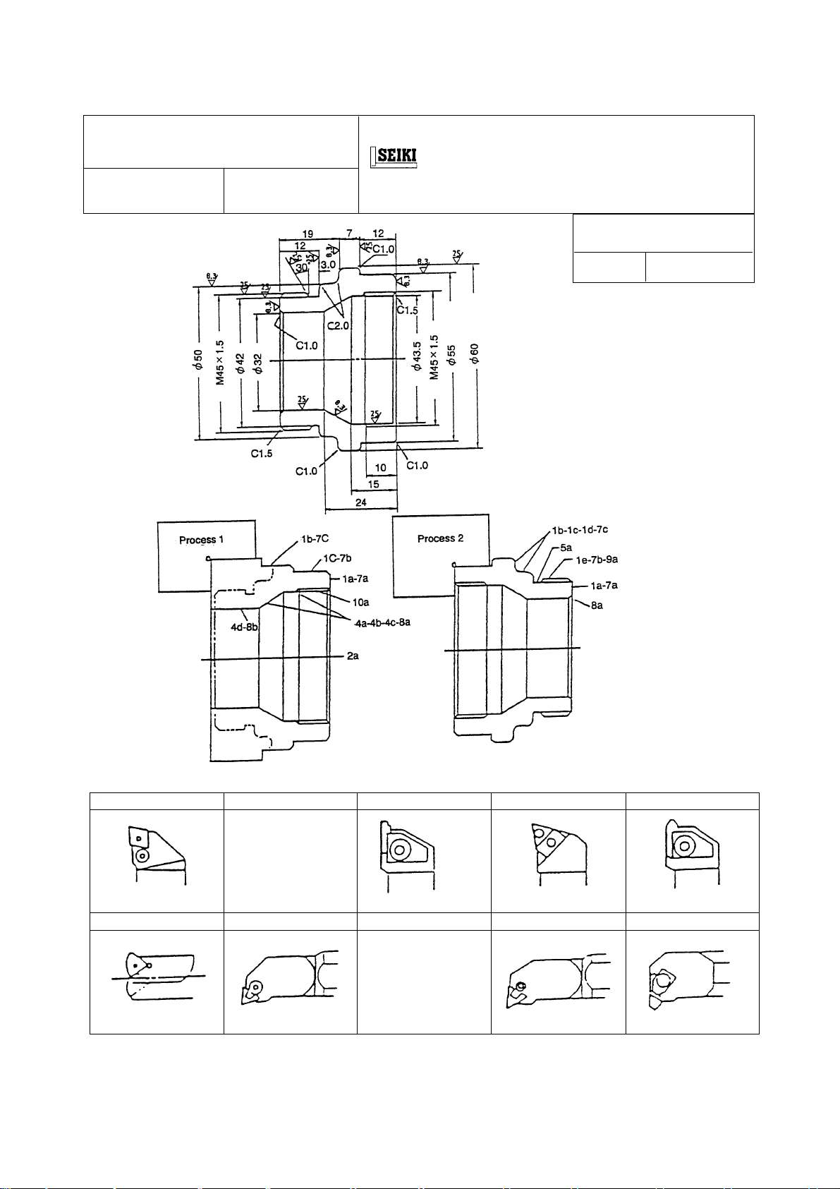
1-2 Tool Layout
Example of tool layout for chuck work
Process :
Process 1, 2
NC unit
CNC LA THE:
TOOL LAYOUT DRAWING
Part name SAMPLE
Material
S48C
R0.8
OD roughing
T1 T3 T5 T7 T9
Width 2mm
OD grooving
R0.8
OD finishing
OD threading
T2 T4 T6 T8 T10
R0.8
φ20 ID finishing
φ25 ID threading
φ30
R0.8
φ20 ID roughing
1 - 4
Page 11

1-3 NC Address and Range of Command Value
Function Address Range of command value
Program No. O 1~99999999
Sequence No. N 1~99999999
Preparatory function G 0~999
Coordinate value X, Y, Z, U, V, ±99999.999(mm) ±9999.999(inch)
W, I, J, K, Q, ±99999.999(deg) ±99999.999(deg)
R, A, B, C
Feedrate F 0.001~999.999(m/rev) 0.0001~99.9999(inch/rev)
Spindle function S 0~99999999
Tool function T 0~999999
Auxiliary function M 0~99999999
Dwell P, X, U 0~99999.999(sec)
Call up program No. P 1~99999999
Number of repetition L 1~99999999
1 - 5
Page 12

1 - 6
Page 13

2. PROGRAMMING
2-1 Basis for Programming
2-1-1 Program Reference Point and Coordinate Values
For a CNC lathe, coordinate axes X and Z are set on the machine and their intersecting
point is called a “program reference point”. The X axis assumes a spindle center line to
be a position of “X0”, and the Z axis assumes a workpiece finish end face on the tail stock
side to a position of “Z0”.
To move a tool, specify its moving position, adding signs “+” and “−” to both X and Z axes,
with this program reference point as a datum point.
•Position of the tool A ...
Since it is locates a plus 50 dia. on the X-axis and plus 35mm (1.4”) on the Z-axis,
X50.0 Z35.0 ..... (Omit the plus sign)
•Position of the tool B ...
Since it is locates a plus 80 dia. on the X-axis and minus 25mm (1.0”) on the Z-axis,
X80.0 Z−25.0
2 - 1
Page 14

2-1-2 Regarding Machine Zero Point
Properly speaking, the machine zero point and reference point is a different position,
however, as for our NC lathe make the both points the same position.
Therefore, here in after the reference point calls as the machine zero point in this manual.
It is a position which is the machine proper and the machine zero point which is the basis
of program set the end of each axis.
This machine zero point utilizes an electrically identical point, a grid point, and stop a
servo motor at the certain point.
Turn on the power at the starting time in the morning, it can be entered a program
operation .
2 - 2
Page 15

2-1-3 Program Example
NC Program
2 - 3
Page 16

2-2 Details of F, S, T and M Functions
2-2-1 F Function (Feed Function)
G99 mode F ooo.ooo(Up to 6 digits in increment of 0.001)
mm/rev Specify a cutting “feed rate” per spindle revolution or a lead of the threading.
(Example) 0.3 mm/rev = F0.3 or F30
1.0 mm/rev = F1.0 or F100
1.5 P thread = F1.5 or F150
In case of thread cutting, it is possible to command down to 5 digits of decimals.
F
ooo.ooooo(0.00001 unit; max. 8 digits)
Max. feed rate 5,000mm/min.
A maximum feed rate depends on the spindle speed used.
Assuming the spindle speed to be N;
5000
N
(Example) When the spindle speed is 1,000 rpm, the maximum feed rate is;
G98 mode F
mm/min Feed rate per minute
oooooo A decimal point cannot be used.
Generally, you specify a feed rate per spindle revolution for in case of turning.
However, if specified in the G98 mode,
(Example) 200 mm/min = F200
5000
1000
= 5.0 F = 5.0 mm/rev
a feed rate per minute is set.
2 - 4
Page 17

Notes) 1. Since the G99 mode is set when turning on the power, you do not have to specify it,
unless G98 is to be used.
2. A cutting feed in taper cutting or circular cutting is that of a tool advance direction
(tangent direction).
3. If a cutting feed in G98 mode (G01, G02, G03) is specified, the turret head moves even
if the spindle is not running.
4. When commanding G98 from G99 mode or G99 mode from G98, be sure to command
F .... as well.
In case of F command is missing in the block, F value is effective which is designated
just preceding block in G98, G99 mode respectively.
To be concrete, it becomes as follows:
Indicate “F” that becomes effective in that block with [ ] .
(Feed per minute) (Feed per revolution)
When the power is turn ON 0 0.00
N1 G99 F1.23 ; 0 [1.23]
N2 —— ; 0 [1.23]
N3 G98 F1000 ; [1000] 1.23
N4 —— ; [1000] 1.23
N5 G32 F2.34567 ; 1000 [2.34567]
N6 —— ; 1000 [2.34567]
N7 G99 ; 1000 [2.34]
N8 —— ; 1000 [2.34]
N9 G98 ; [1000] 2.34
N10 —— ; [1000] 2.34
N11 G32 ; 1000 [2.34567]
2-2-2 S Function (Spindle Function)
Specify a spindle speed or surface speed (cutting speed) with S 4-digit numeral
(S
oooo).
Command Description
oooo Max. spindle speed limit
G50S
(Example) G50 S1800 : A maximum spindle speed is limited to 1,800 (mim
oooo Constant surface speed cancel
G97S
Specify a spindle revolution with S
(Example) G97 S1000 : A spindle speed per minute is set to 1,000 (mim
2 - 5
oooo .
−1
)
−1
)
Page 18

G96S
oooo Constant surface speed control
When performing constant surface speed control, specify a cutting speed “V”
(m/min) with an S 4-digit code (S
(Example)G96 S150 : A spindle speed is controlled to 150
oooo ).
150 m/min cutting speed at the cutting point.
..... Refer to the left figure.
* Formula for calculating the spindle speed from the
surface speed
N =
1000 × V
π
× D
V : Surface speed (m/min)
π : 3.14
D : Tool nose position (ø mm)
-1
N : Spindle speed (mim
Spindle speed “N” at the position A = = 1193 (mim
Spindle speed “N” at the position B = = 795 (mim
Spindle speed “N” at the position C = = 682 (mim
)
1000 × 150
3.14 × 40ø
1000 × 150
3.14 × 60ø
1000 × 150
3.14 × 70ø
-1
)
-1
)
-1
)
As mentioned above, an automatic change of the spindle speed relating to the work
diameter is called as the constant surface speed control.
Notes) 1. Considering a workpiece chucking condition, specify the maximum spindle speed limit
with S 4-digit code in a G50 block at the beginning of a program.
2. When roughing with G96, calculate maximum and minimum spindle speeds so that
cutting will be performed in a constant power range as much as possible.
3. When changing over from G96 to G97 and vice versa, specify not only a G code, but
also an S code.
4. When changed over from G96 to G97 and no S code is specified, the spindle is run with
the speed specified in the latest S code in G96 mode.
5. When changed over from G96 to G97 and no S code is specified, the spindle turns with
the previously used surface constant speed is S code had been specified in G96 mode.
Also, when no S code is specified in G96 mode, S results in 0.
2 - 6
Page 19

6. The following interlocks are provided as the rotating conditions of spindle.
(1) The direction of the chuck inner clamp and outer clamp key shall be the same
direction as that of chuck clamping.
(2) Q-setter shall be stored.
(3) Rotating speed shall be command with G96 Sxxx.
(4) The lamp of advance or retract of center support shall be on. (Option)
(5) The door shall be closed.
2 - 7
Page 20
2-2-3 T Function (Tool Function)
The tool used and its offset No. can be selected with a 4-digit number following “T”.
Turret face selection Offset No.
Face 01 ~ maximum number of faces
1. Setting Coordinate of Tool-nose Position
As a general usage, it is not necessary to command of offset No. Only command of
calling of turret as shown below can set the tool-nose position.
Example) If the turret No. 3 is to be called, program as follows:
2. Setting Coordinate of Tool-nose Position for Arbitrary Offset No. When using an
arbitrary offset No., program as follows.
Setting is done with the tool mounting position (diameter, length) of the offset No. 13.
Example)
oo∆∆
T
T0300
T0313
Turret No. 3 Offset No.
selected
Note 1. Be sure to input the tool-nose point on the tool layout screen.
2. Input “9” to the tool-nose point for drilling end-milling tool. (When a rotating tool
is equipped.)
Caution When “T ∆ ∆” command is specified on the same line as the axis travel command,
the indexing of turret is made simultaneously with traveling and a coordinate is set
after completion of traveling.
Be careful not to command T function together with the travel command.
2 - 8
Page 21

3. Compound Offset
When an adjustment is made on diametrical dimension of 50 and 70mm respectively at
the following workpiece, two or more offset can be applied on one tool.
Example 1)
T0900
G97 S2546 M08
G00 X50.0 Z10.0 M03
G96 Z3.0 S200
G01 Z−15.0 F0.2
X70.0 T0919 Compound offset
Z−40.0 Offset No. 19
X84.0 T0900 Compound offset
cancel
G00 G97 Z10.0
G30 U0 W0
M01
Example) Input status of dimension adjustment when the part
0.03.
OFFSET
XZRT
19 0.03 0
Note) Be sure to input zero for R and T.
Example 2) Cutting with taper of −0.3 at
T0500
G97 S2000 M08
G00 Z3.0 M03
G01 X24.0 F1.0
G00 G97 Z10.0
OFFSET
25 X-0.3 Z0 R0 T0
G30 U0 W0
0 0
φ30 part
X40.0
Z1.0 F0.2
X30.0 Z−2.0
Z−90.0 T0525 Compound offset
X57.00 T0500 Compound offset
X62.0 Z−92.5 cancel
X68.0
M01
φ70 is made larger by
Offset No. 25
2 - 9
Page 22

4. Multi tool compensation
When set up tools 2 or more on the same face on the turret described below, give
plural compensation on a face and set up the coordinate for each tool respectively.
Command system of compound compensation,
different one by setting data in nose radius and control point.
(Example) N100 T0100 A tool with turret face No.1 is indexed and setting-up
〜
T0131 A tool with turret face No.1 is indexed and setting-up
〜
Note 1) When a tool, which is not required tool point and tool nose R such as drill etc., is
applied to multi tool, set a tool point as 9. (Tool nose R may be set as zero.)
2) When set the Q setter, the cursor position of tool offset coincide with the tool No.
mounted on the turret face indexed at machining position at this moment.
Any No. can be selected by moving the cursor by cursor key.
Multi tool compensation and compound compensation is divided by data of tool
point and tool nose R as follows:
Tool nose R and tool point of offset No. on effect the compound compensation
and multi tool compensation.
is performed by the data of offset No.1.
is performed by the data of offset No.31.
and furthermore, set up tools deem as
1 Both tool nose R and tool point are zero
2 Data of tool point from 1 to 9 and setting of tool nose R
→ Compound compensation
→ Multi tool cutting
3 Tool point is zero and set a tool nose R
2 - 10
→ Alarm (No.182)
Page 23

5. Program example
T01
T06
T03
Turret face No.1
Offset No.1
Turret face No.3
Offset No.3
Turret face No.6
(Compound compensation 33, 34) (Offset No.6, Multi tool
conpensation, 36)
N100 T0100 The turret face No.1 is indexed and setting-up is
〜
performed by the data of offset No.1.
M01
N300 T0300 The turret face No.3 is indexed and setting-up is
〜〜〜〜〜〜
performed by the data of offset No.3.
G01 Z− T0333 Compound compensation ON (Offset No.33)
X Z T0334 Compound compensation ON (Offset No.34)
T0300 Cancel compound compensation (Offset No.3)
M01
N600 T0600 The turret face No.6 is indexed and setting-up is
performed by the data of offset No.6.
T0636 Multi tool compensation ON (Offset No.36)
M01
Example of compensating data
No. X Z R T
01 Q-setter Q-setter 0.8 3
03 Q-setter Q-setter 0.8 3
06 Q-setter Q-setter 0.4 2
33 Extremely Extremely
small amount small amount 0 0
34 Extremely Extremely
small amount small amount 0 0
36 Q-setter Q-setter 0.4 2
2 - 11
Page 24

2-2-4 M Function (Miscellaneous Function) List
Please refer to the details on the Delivery specifications
as to the discrimination between Standard or Option.
M code Function Description
M00
M01
M02
PROGRAM STOP
OPTIONAL STOP
PROGRAM END
This code can stop the machine during its operation,
when measuring a workpiece or removing cutting chips.
(The spindle and coolant also stop.) To restart, press
the CYCLE START key. However, since the spindle and
coolant are being suspended, specify M03/M08 in a
subsequent block.
Same function as M00.
An M01 command on a program can be either executed
or ignored by means of the OPTIONAL STOP key on the
operation panel.
Executed when a lamp is lit up.
(optional stop is effective)
Sheet key
This code is used in the tape operation and is
programmed at the end of the program.
Ignored when a lamp is lit off.
(optional stop is not effective)
M03
M04
M05
M07
M08
M09
M12
SPINDLE FORWARD
START
SPINDLE REVERSE
START
SPINDLE STOP &
ROTARY TOOL STOP
OPTIONAL COOLANT
START
COOLANT STA RT
COOLANT STOP
WORK COUNT
It stops the spindle and coolant, and resets NC.
Viewing from the spindle motor side, this code starts the
spindle in the clockwise direction.
Viewing from the spindle motor side, this code starts the
spindle in the counterclockwise direction.
This code stops the spindle.
When changing over spindle revolution from forward to
reverse (or the other way), stop the spindle once with
M05, and then specify M04 (M03).
This code starts discharging coolant.
This code stops discharging coolant.
Normally, this code starts a work counter or tool counter
to count up.
Note) : • M05 and M09 are executed after the completion of the axes travel.
• Do not specify M codes in the same block duplicately.
2 - 12
Page 25

M code Function Description
M13
M14
M15
M18
M19
M23
ROT ARY TOOL
FORWARD ROTATION
ROT ARY TOOL
REVERSE ROTATION
ROT ARY TOOL STO P
SPINDLE
POSITIONING OFF
SPINDLE
POSITIONING
CHAMFERING ON
The rotary tool runs in the forward direction at C-axis coupling
time.
The rotary tool runs in the reverse direction at C-axis coupling
time.
Stops the rotary tool spindle .
Cancels M19.
Indexes the spindle by one position.
This code performs automatic thread chamfering during a
threading cycle (G92). A chamfering length can be set in
the parameter in increment of 0.1 L.
M24
M25
M26
M28
M30
M31
CHAMFERING OFF
T AILSTOCK ADV ANCE
TAILSTOCK RETRACT
CENTER STOPOVER
RETRACT
END OF PROGRAM,
NC RESET & REWIND
NO-WORKPIECE
CHUCK& COUNT UP
CHECK
When M23 is specified.
This code cancels M23.
Use when the center position detector is set.
End of the program in case of memory operation. Stops
the spindle and coolant, and resets the NC unit to return
the program to the beginning. Specify this code in an
independent block.
1. Tool life check
2. Work quantity check of the preset work counter
3. No-workpiece check when the bar feeder is attached
2 - 13
Page 26

M code Function Description
M32
M33
M34
M36
M37
M38
M39
TOP CUT CHECK
TOP CUT RESET
BAR LOAD COMMAND
POWER OFF IS
EFFECTIVE AT
PROGRAM STOP
POWER OFF IS NOT
EFFECTIVE AT
PROGRAM STOP
CENTER AIR BLOW
ON
CENTER AIR BLOW
OFF
Block ship ON, however, block skip becomes OFF by the
top cut signal ON.
Reset the top cut signal.
Power is off by command of M00, M01, M02 or M30
when the power cut off is ON.
Power does not off even the command of M00, M01, M02
or M03 when the power cut off is ON.
Air is blown to the center.
Stop the air.
M40
M41
M43
M44
M45
M46
SPINDLE LOW
WINDING SELECT &
CANCEL C-AXIS
COUPLING
SPINDLE HIGH
WINDING SELECT &
CANCEL C-AXIS
COUPLING
C-AXIS COUPLING ON
ROTARY TOOL
COUPLING ON
ROTARY TOOL
COUPLING OFF
SPINDLE OVERRIDE
30 ~ 1000min
30 ~ 6000min
-1
-1
Switches from the cutting mode to the milling (rotary tool)
mode.
The spindle override can be applied.
M47
IS EFFECTIVE
SPINDLE OVERRIDE
IS NOT EFFECTIVE
The spindle override is ignores.
2 - 14
Page 27

M code Function Description
M48
M49
M51
M52
M53
M54
M55
FEEDRA TE OVERRIDE
IS NOT EFFECTIVE
FEEDRA TE OVERRIDE
IS EFFECTIVE
SPINDLE AIR BLOW
ON
SPINDLE AIR BLOW
OFF
TOOL EDGE
MEASURING SENSOR
AIR BLOW ON
TOOL EDGE
MEASURING SENSOR
AIR BLOW OFF
TOOL EDGE
MEASURING ARM OUT
The feedrate override can be applied.
The feedrate override is ignores.
Discharge the air at the chuck section.
Stop the air.
Air is blown to the measuring sensor section.
Air blow at the sensor section stops.
Measuring sensor swings out.
M56
M61
M62
M63
M64
M65
M66
M67
M68
TOOL EDGE
MEASURING ARM
RETURN
AUTO DOOR OPEN
AUTO DOOR CLOSE
UNLOADER ADV ANCE
UNLOADER RETRACT
BAR FEEDER SUPPL Y
COMP.CHECK(ASQ 80)
CHUCK CLAMPING
PRESSURE IS LOW
CHUCK CLAMPING
PRESSURE IS HIGH
CHUCK CLOSE
Measuring sensor is stored.
The door opens by a program command.
Closes the door.
This function is the bar feeder start check of bar feeder
(ASQ type) made by ALPS.
The pressure of spindle chuck shift to low side.
The pressure of spindle chuck shift to high side.
The spindle chuck closes.
M69
M70
CHUCK OPEN
SP ARE OUTPUT
SIGNAL
The spindle chuck opens.
For bar feeder (ASQ type) made by ALPS.
2 - 15
Page 28

M code Function Description
M71
M72
M73
M74
M75
M76
M81
WORK MEASURING
ARM OUT
WORK MEASURING
ARM RETURN
WORK MEASURING
SENSOR AIR BLOW
ON
WORK MEASURING
SENSOR AIR BLOW
OFF
CHIP CONVEYOR
START
CHIP CONVEYOR
STOP
ROBOT SERVICE
Work measuring sensor swings out.
Work measuring sensor is stored.
Air is blown to work measuring sensor.
(In the custom macro of WORK MEASUREMENT
FUNCTION)
Air blow at the measuring sensor stops.
(In the custom macro of WORK MEASUREMENT
FUNCTION)
Chip conveyor rotates to normal direction.
Chip conveyor stops.
ROBOT START-1
M82
M83
M84
M88
M89
M98
REQUEST-1
ROBOT SERVICE
REQUEST-2
AUTO PRESETTER
CHUCK INTERLOCK
OFF
AUTO PRESETTER
CHUCK INTERLOCK
ON
MACHINE PROPER
STANDBY
FEEDER STANDBY
OFF
SUBPROGRAM
CALLING
ROBOT START-2
When measuring arm swings, chuck open/close condition
is neglected.
When measuring arm swings, chuck open/close condition
becomes effective.
The NC unit temporarily stand by. It is restarted by cancel
signal from the robot.
Robot on standing by is restarted by cancel signal from
the machine.
This code switches program from a main program to a
subprogram.
M99
M100
SUB PROGRAM END
C - AXIS BRAKE ON
This code returns control from a subprogram to a main
program. If specified in the main program, the program
returns to its top.
Used during C-axis couplig. With the brake applied,
spindle rotation or C-axis move are disabled.
2 - 16
Page 29

M code Function Description
M101
M102
M110
M111
M122
M123
M132
C - AXIS BRAKE OFF
SPINDLE FORWARD
START (CHUCKING
CONDITION IS
NEGLECTED)
TURRET HEAD AIR
BLOW ON
TURRET HEAD AIR
BLOW OFF
AIR BLOW FROM
SPINDLE ON
AIR BLOW FROM
SPINDLE OFF
SPINDLE THROUGH
COOLANT ON
Air is blown from turret head.
Air blow from iturret head stops.
Air is blown inside spindle.
Air blow from inside spindle stops.
Dischage the coolant from spindle.
M133
M140
M141
M142
M143
M144
M145
M162
SPINDLE THROUGH
COOLANT OFF
WORK SETTING CHECK
M CODE EXTERNAL
FUNCTION 1
M CODE EXTERNAL
FUNCTION 2
M CODE EXTERNAL
FUNCTION 3
M CODE EXTERNAL
FUNCTION 4
M CODE EXTERNAL
FUNCTION 5
SP. ROTATE CW + AIR
Stops dischaging the coolant from spindle.
M163
BLOW ON
SP. ROTATE CW + AIR
BLOW OFF
2 - 17
Page 30

M code Function Description
M167
M171
M172
M173
M174
M201
~
M231
DOOR OPEN +SP. STOP
+COOLANT STOP
AUTO DOOR OPEN
(ONE SHOT)
AUTO DOOR CLOSE
(ONE SHOT)
CENTER FORWARD
(ONE SHOT)
CENTER RETRACT
(ONE SHOT)
ROBOT SERVICE
REQUEST 1
~
ROBOT SERVICE
REQUEST 31
M260
M263
M264
M285
M286
M292
M293
WORK SETTING
CHECK SOL ON (ONE
SHOT)
UNLOADER FORWARD
(ONE SHOT)
UNLOADER RETRACT
(ONE SHOT)
SPINDLE SPEED
CHANGE CONTROL ON
SPINDLE SPEED
CHANGE CONTROL
OFF
CENTER FORWARD OT
LS DISABLE
CENTER FORWARD OT
LS ENABLE
2 - 18
Page 31

Example of Subprogram Call
(Example)
Main Program Subprogram
N001 —————— ; O101 ; O401 ;
N002 —————— ; N102 —————— ; N402 —————— ;
N003 —————— ; N103 M98 P401 ; N403 —————— ;
N004 M98 P101 ; N104 —————— ; N404 —————— ;
N005 —————— ; N105 M99 ; N405 M99 ;
N006 ;
N007 M98 P201 L2 ; O201 ;
N008 —————— ; N202 —————— ;
N009 —————— ; N203 —————— ;
N010 —————— ; N204 M99 ;
N011 —————— ;
N012 M98 P301 ; O301 ;
N013 —————— ; N302 —————— ;
N014 —————— ; N303 M99 P015 ;
N015 —————— ;
N016 M99 P018 ;
N017 —————— ;
N018 —————— ;
Note 1) Another subprogram can be called from one subprogram.
Although the example above calls subprograms doubly, they can be call
quadruply at most.
2) One call command can repeatedly call the subprogram for 99999999 times
running.
3) When the subprogram ends, if a sequence number is specified with P, control
does not return to next to the program called by a parent, but to the sequence
number specified with P’.
2 - 19
Page 32

2-3 Details of G Function
2-3-1 List of G Function
Group G code Function
01 G00 Positioning (Rapid traverse)
G01 Linear interpolation
G02 Circular arc interpolation/Helical interpolation CW
G03 Circular arc interpolation/Helical interpolation CCW
G04 Dwell
G07 Hypothetical axis interpolation
00 G09 Exact stop
G10 Data setting
G11 Data setting mode cancel
G17 Xp - Yp plane designation Xp: X-axis or its
02 G18 Zp - Xp plane designation Yp: Y-axis parallel
G19 Yp - Zp plane designation Zp: Z-axis axis
06 G20 Inch input
Please refer to the details on the Delivery specifications
as to the discrimination between Standard or Option.
}
G21 Metric input
04 G22 Stored stroke check ON
G23 Stored stroke check OFF
00 G28 Reference point return
G30 2nd, 3rd and 4th reference point
G31 Skip function
01 G32 Thread cutting
G34 Variable lead thread cutting
00 G38 Tool tip R compensation/Tool radius compensation vector retention
G39 Tool tip R compensation/Tool radius compensation corner circular arc
G40 Tool radius compensation cancel
07 G41 Tool radius compensation left side
G42 Tool radius compensation right side
G50 Coordinate system setting/Setting of maximum high speed of spindle
00 G52 Back face machining mode
G53 Machine coordinate system selection
12 G54 Work length alteration 1
G55 Work length alteration 2
00 G59 Local coordinate system setting
2 - 20
Page 33

Group G code Function
13 G61 Exact stop mode
G64 Cutting mode
00 G65 Macro calling
14 G66 Macro modal calling
G67 Macro modal calling cancel
G70 Finishing cycle
G71 OD/ID roughing cycle
G72 End face roughing cycle
00 G73 Closed loop turning cycle
G74 End face cutting-off cycle
G75 ID/OD cutting-off cycle
G76 Multi-type thread cutting cycle
G80 Drilling cycle cancel
G81 Drilling cycle, Spot drilling cycle
G82 Drilling cycle, Counter boring cycle
G83 Peck drilling cycle
G831 Peck drilling cycle
G84 Tapping cycle
G841 Reverse tapping cycle
09 G842 Direct tapping cycle
G843 Reverse direct tapping cycle
G85 Boring cycle
G86 Boring cycle
G861 Fine boring cycle
G87 Back boring cycle
G88 Boring cycle
G89 Boring cycle
G90 OD/ID turning cycle
01 G92 Single type thread cutting cycle
G94 End face turning cycle
G96 Constant surface speed control
17 G196 Constant surface speed control (Back face)
G97 Constant surface speed control cancel
05 G98 Feed per minute (mm/min)
G99 Feed per rotation (mm-1)
22 G120 Polar coordinate interpolation mode cancel
G121 Polar coordinate interpolation mode
2 - 21
Page 34

Group G code Function
00 G128 Scroll cutting speed control
18 G130 Tool life management OFF
G131 Tool life management ON
27 G140 Automatic tool tip R compensation/Tool radius compensation cancel mode
G143 Automatic tool tip R compensation effective mode
G144 Automatic tool tip R compensation effective mode (G144 = G143)
G145 Tool radius compensation effective mode
00 G141 Automatic tool tip R compensation left side
G142 Automatic tool tip R compensation right side
G150 Groove width compensation cancel
16 G151 Groove width compensation for end face
G152 Groove width compensation for OD/ID
25 G170 Front face machining mode
G171 Back face machining mode
00 G194 External measurement compensation
10 G198 Initial point return of fixed cycle for drilling
G199 R point return of fixed cycle for drilling
G251 Multi-buffer
G261 S designation for spindle
00 G262 S designation for rotating tool
G263 S designation for sub spindle
G271 Cylindrical interpolation
15 G501 Programmable mirror image reset
G511 Programmable mirror image set
00 G921 Work coordinate system preset
Note 1) When the source power is switched on, those G codes marked are
set.
2) G codes of 00 group indicate those which are not modal, and are effective to the
blocks indicated.
3) When G codes which are not listed in G Code List are commanded, alarm is
displayed, and when G codes which don’t have corresponding options, alarm is
displayed.
4) Any numbers of G codes can be commanded in the same block, if they belong to
different groups.
When two or more of G codes which belong to the same group are commanded,
G code later commanded becomes effective.
2 - 22
Page 35

2-3-2 G50 Maximum Spindle Speed Setting
Using a command “G50 S ....... ;” , you can directly specify the upper limit value of a
spindle speed (min
−1
) with a 4-digit numerical value following an address S.
When a S beyond the upper limit has commanded after this command, it is clamped at
this upper limit.
Even in constant surface speed control (G96 mode), the spindle rotation speed for the
specified surface speed (m/min. or ft/min. ) will be clamped to this upper limit.
(Example) G50 S2000 ;
Fixes the maximum spindle speed to 2,000 min
Note: Depending on a workpiece loading state, specify the maximum spindle speed (G50
××××) at the beginning of the program.
S
2-3-3 G00 Positioning
Specify this G code when feeding a tool by rapid traverse. This is used when approaching
the tool to the workpiece or when retreating it after cutting is completed.
−1
Chuck work
1. Specify 2 axes simultaneously from the point
“a” to the point “b”.
G00 X100.0 Z0.2
2. From the point “b” to the point “a”
G00 X200.0 Z200.0
Center work
Specify one axis when there is any
interference.
1. From the point “a” to the point “b”
G00 Z3.0
From the point “d” to the point “c” X80.0
2. From the point “c” to the point “b”
G00 X200.0
From the point “b” to the point “a” Z20.0
Note: When simultaneously positioning both the X and Z axes, the tool does not linearly move
from a current position to a specified position, because their rapid traverse rates differ
from each other. Therefore, you must be careful when there is an interfering substance
halfway a tool path.
2 - 23
Page 36

After one of 2 axes (X and Z) has completed its
move, the other one moves to a specified point.
The tool does not move linearly as shown with a
dotted line in the left figure.
When moving to the next cutting position
When moving the tool to the next cutting position, do so at a rapid traverse rate after retreating it
by about 2 to 3 mm from a cut surface.
End face OD cutting
End facing G01 X45.0 F0.3
Retreat
To the point “a” G00 X100.0
Next command G01
ID cutting
ID cutting G01 Z
Retreat X46.0
To the point “a” G00 Z10.0
To the point “b” X200.0 Z200.0
Z3.0
Z oooo
−43.0 F0.2
2 - 24
Page 37

2-3-4 G01 Linear Cutting
(1) Specify this G code when performing linear cutting (ordinary cutting).
Chamfering and taper cutting are also considered linear cutting.
Use an F code to specify a feeding rate.
Absolute programming
A P1 G00 X90.0 Z5.0
Incremental programming
*
P1 G00 X90.0 Z5.0
P2 G01 W
P3 U6.0
P4 X100.0 W
P5 W
P6 G00 X
−55.0 F0.3
−2.0
−28.0
ooo. oo
P2 G01 Z
P3 X96.0
P4 X100.0 Z
P5 Z
P6 G00 X ooo. oo
* Absolute programming means to specify the
position with X and Z coordinates from work
coordinate zero point.
This is also called an incremental value
programming method. This method
specifies tool strokes from a current position
(start point) to the next point with U (X axis)
and W (Z axis).
An end point of the previous block becomes
a start point of the next block.
−50.0 F0.3
−52.0
−80.0 F0.2
The end point of a previous block becomes the start point of the next block. X and W
(or U and Z) can be used in the same block.
Note: 1) Be sure to specify an F function in the first G01 command in the program.
2) Even if the G00 command is commanded next to G01, the feed rate given with
an F code is kept.
2 - 25
Page 38

(2) Chamfering, corner R command
When there is chamfering (45°chambering) or corner R (quarter circle) between 2
blocks which are parallel with the X or Z and cross with each other at a right angle,
specify as follows:
For chambering For corner R
(a) G01 X ... K ... F ... (c) G01 X ... R ... F ...
(b) G01 Z ... I ... F ... (d) G01 Z ... R ... F ...
X and Z coordinate values .. Position after chambering or corner R cutting
I, K, R .................................. Radius designation. Signs “
directions from the starting point, and a numerical
value is a size of chamfering or corner R.
For the direction [1]
G01 X50.0 K
For the direction [2]
G01 Z0 I
For the direction [3]
G01 X20.0 K−2.0
For the direction [4]
G01 Z0 I2.0
For the direction [5]
−2.0
−2.0
+” and “−” represent
G01 X50.0 R−2.0
For the direction [6]
G01 Z0 R−2.0
For the direction [7]
G01 X20.0 R−2.5
For the direction [8]
G01 Z0 R2.5
Note: 1) When specifying a tool movement with G01 for chamfering or corner R, it must
be either one axis of X and Z.
In the next block, the other one axis of X and Z, which crosses the former axis
at a right angle, must be given.
2) The stop point by a single block operation is a point after chamfering or corner
R cutting.
2 - 26
Page 39

(3) Angle designated linear interpolation
The angle designated linear interpolation can be performed by designating the angle A
formed by the X or Z axes and
X (U)
+Z-axis.
G01
.........A..... F......;
{}
Z (W)
The range of the angle is
CCW angle from
+Z-axis is regarded as plus and the CW angle is as minus.
2-3-5 G02, G03 Circular Cutting
Specify either G02 or G03 when performing circular cutting.
−360.0 ≦A ≦ 360.0 (deg).
(1) G01 X50.0 A150.0 F0.3;
(2) G01 Z
The direction of arc rotation on the X-Z
plane is as illustrated below.
−100.0 A−180.0;
A circular command consists of the following 3 factors:
[1]Circular arc direction G02 or G03
[2]X and Z coordinate values of a
circular arc end point
[3]Circular arc radius R (radius
designation)
Example : G01 Z−25.0
G02 X70.0 Z−40.0 R15.0
↑↑ ↑
[1] [2] [3]
2 - 27
Page 40

(Example 1)
When moving from the point A to the point B
G02 X60.0 Z0 R20.0 F...;
When moving from the point B to the point A
G03 X100.0 Z
(Example 2)
When moving from the point A to the point B
G03 X60.0 Z0 R20.0 F...;
When moving from the point B to the point A
G02 X100.0 Z
−20.0 R20.0 F...;
−20.0 R20.0 F...;
(Example 3)
When moving from the point A to the point B
G02 X60.0 Z0 R50.0 F...;
When moving from the point B to the point A
G03 X80.0 Z
2 - 28
−10.0 R50.0 F...;
Page 41

(Example 4)
When moving from the point A to the point B
G03 X60.0 Z0 R50.0 F...;
When moving from the point B to the point A
G02 X80.0 Z
(Example 5)
When moving from the point A to the point B
G03 X45.0 Z
When moving from the point B to the point A
G02 X0.0 Z0 R25.0 F...;
−10.0 R50.0 F...;
−35.9 R25.0 F...;
(Example 6)
When moving from the point A to the point B
G03 X40.0 Z
When moving from the point B to the point A
G02 X40.0 Z0 R20.0 F...;
−40.0 R20.0 F...;
2 - 29
Page 42

• Circular command exceeding 180°
When specifying a circular arc exceeding 180°, give a minus sign such as R
When moving from the point A to the point B
G03 X30.0 Z
When moving from the point B to the point A
G02 X30.0 Z−17.5 R−25.0 F...;
Cutting feed rate
The cutting feed rate commanded by F code becomes the speed that a tool moves on
a circular arc.
−62.5 R−25.0 F...;
−∆∆. ∆∆.
Note: 1) When F code has not feed commanded in G02 and G03 blocks or before that,
an alarm will occur.
2) Exponent type acceleration/deceleration is engaged.
3) When radius of circular arc = 0 is commanded, an alarm will occur.
4) If the end point is not located on the circular arc, the tool will move on the
remainder in straight line after moving in circular, when an error of the end point
of circular interpolation is less than the parameter setting value(No.3459). And
when it is out of the parameter setting value, an alarm will occur.
5) When I, J, K and R are commanded in the same block, R has priority.
2 - 30
Page 43

2-3-6 G04 Dwell
A tool can be rested during a command time.
(Example)
When stopping the tool for 2 seconds
G04 U2.0;
In order to stabilize the diameter of the groove shown
in the left figure, it is necessary to dwell the tool for 1
revolution or more at the bottom of the groove.
-1
Assuming the spindle speed “N” to be 600 min
, the
time “T” required for 1 revolution is;
60
T = = = 0.1 second
N
60
600
Therefore, stop the tool for 0.1 second or more.
G01 X40.0 F...;
G04 U0.2 In this case, the feed was made
interrupted for 0.2 second.
X55.0 F...;
2-3-7 G09 Exact Stop
When G09 is commanded in the same block with a moving command, the machine is
decelerated to stop and the next block is executed after checking that the position of the
machine is within the range designated as a command position.
Only commanded block is effective.
(1) Command form
G09 —— ;
(2) Program example
N1 G09 G01 U50. F ;
N2 G01 W -50. ;
When commanding G09, an edge is
created on the corner.
When not commanding G09, a round is
created on the corner.
2 - 31
Page 44

2-3-8 G61 Exact Stop
The machine is decelerated to stop at the end point until G62, G63 and G64 etc. are
commanded after commanding G61, and the next block is executed after checking that the
position of the machine is within the range commanded.
Program example
G61 G01 Z
−100.0 F0.2
X20.0
−150.0
Z
G61 mode effective :
An edge is created on the corner.
G61 mode ineffective :
A round is created on the corner.
2-3-9 G10 Programmable Date Input
It-is possible to change various data for work shift and offset on the N/C program.
(1) Work shift amount input
G10
P00 X (U) Z (W) ;
P00 : Work shift amount input designation
X (U) : Work shift amount of X-axis
Z (W) : Work shift amount of Z-axis
Generally, setting of an offset amount is performed for only the value of Z.
Don’t perform work shift for other axes.
(Example) G10 P00 Z512.368;
(2) Form offset amount input
G10
L10 P X (U) Z (W) R Q H ;
L10 : Form offset input designation
P : Offset No. (0 ~ Maximum offset sets)
X (U) : Form offset amount of X-axis
Z (W): Form offset amount of Z-axis
R : Tool nose R (Absolute)
Q : Virtual tool nose point (0 ~ 9)
H : Tool width (Absolute)
2 - 32
Page 45

(3) Wear offset amount input
G10
L11 P X (U) Z (W) R H ;
L11 : Wear offset amount input designation
P : Offset No. (0 ~ Maximum offset sets)
X (U) : Wear offset amount of X-axis
Z (W): Wear offset amount of Z-axis
R : Tool nose R (Absolute)
H : Tool width (Absolute)
Note 1) Only when absolute input is performed by the form offset input, the
wearoffset amount of the address input is cleared to 0.
2) R (Tool nose R) and H (Tool width) are performed only by absolute input.
2-3-10 G20, G21 Inch Input/Metric Input
It is possible to select the input unit of a program command either in inch input or in metric
input by G20 or G21 command.
Command form
G20 ; Input unit is inch input
G21 ; Input unit is metric input
The following units are changed by the G20/G21 command.
(a) Feed rate command by F (E is included for thread cutting).
(b) Commands related to positions.
(c) Work reference point shift amount.
(d) Tool offset amount.
(e) A part of parameters.
(f) The unit of one graduation of the manual pulse generator.
(1) The G20/G21 command shall be commanded to the head of the program in the single
block.
(2) When the G20/G21 command is executed, conduct the coordinate system preset.
(3) This function is for selecting the unit of numerical value programmed either in metric or in
inch.
Inch
⇔ Metric conversion isn’t performed.
2 - 33
Page 46

2-3-11 G22, G23 Stored Stroke Limit
Setting of the second or third stroke limit can be set by MDI or program
Example:
G22 X
Command of entering prohibition into the second stroke limit and the second or third stroke
Example:
G23; Entering is possible into the second area.
Note 1) When G23 has commanded, G22 should be commanded in the individual block
−170.0 Z−10.0 I−490.0 K−120.0 (Refer to the sketch on the previous page.)
limit is set.
to make a setting area entering prohibition again.
2) When G22 X
the commanded value.
3) When the power is on, G22 is set automatically.
4) When a parameter is changed, please be sure to push “RESET” key.
It is not changed unless it pushes “RESET” key.
Z I K ; is commanded, the parameter changes automatically to
2 - 34
Page 47

2-3-12 Stroke Limit Check Before Move
If the end point of the block to be executed the automatic operation locates in the
prohibited area, stop the axis travel and make an alarm. Execute a check regarding all
effective matters by the stroke limit 1, 2 and 3.
Interrupt a travel if the end point of executing
block locates in the prohibited area.
(1) If the alarm of stroke limit before move is issued, release the alarm by pressing the rest
button.
(2) The end point of executing block can be calculated by the “Machine coordinate”
“Remaining amount of travel” at this time.
Note) If the travel time of one block is very short, some times becomes an alarm before
setting the remaining amount of travel.
(3) Precautions
(a) Concerning a traveling path of block, a check is not executed.
(b) Concerning an axis which is machine lock condition, a check is not executed.
(c) Checking of a block of G31 is not executed.
(d) Check the axis which has completed the reference point return only.
(e) If the end point locates very close to the prohibited area, it becomes an alarm
occasionally.
+
2 - 35
Page 48

2-3-13 G28 Automatic Reference Point Return
With a command “G28 X (U)ooo. oo Z (W)ooo. oo“, the tool automatically returns to
the machine reference point after moving to the position (intermediate point) specified with
X (U), Z (W). G28 assumes the same rapid traverse rate as G00. After returning to the
machine reference point, the machine reference point lamp lights up.
Machine reference
point
N920 G00 X.....
N922 G28 X200.0 Z200.0
N923 M30
%
As shown in the left figure, the tool returns
to the machine reference point via the
inter-mediate point.
Note) Difference from “G28 U0 W0 ;”
Since U0 W0, which is incremental programming, means that a tool stroke is
0(zero), the current position becomes the intermediate point as it is, and the tool
returns to the machine reference point from that position.
2-3-14 G30 2nd Reference Point Return
(1) A commanded axis can be returned the 2nd reference point automatically.
The 2nd reference point can be set either setting by the parameter for the distance
from the machine zero point previously or process of the 2nd reference point setting.
Refer to the instruction manual for the process of the 2nd reference point setting.
Exactly same motion as the automatic zero return by G28 is executed except returning
to the 2nd reference point by the parameter setting.
2 - 36
Page 49

Program example
O5801
N1 G28 U0
N2 G28 W0 T0100
N3 G50 S1500
N4 G30 U0 W0(G00 X200:0 Z150.0)
N5 M01
N101 G30 U0 W0
N102 T0100
N103 G97 S530 M08
N104 G00 X72.0 Z10.0 M03
N105 G01 G96 Z0.2 F3.0 S120
N106 X0 F0.2
N107 Z3.0
N * . .
N * . .
A program example at left uses the 2nd reference
point (G30) as the turret index position.
A setting of the 2nd reference point execute on the
2nd reference point setting screen after the turret with
maximum protruded tool is moved the position (B point)
which is not interfered position with a machining
workpiece or the chuck etc.
N * . .
N118 G00 G97 X70.0 S545
N119 G30 U0 W0 (G00 X200.0 Z150.0)
N120 M01
. .
. .
. .
N1001 G30 U0 W0
N1002 T1000
N1003 G97 S695 M08
N1004 G00 X30.0 Z15.0 M03
N1005 G01 G96 Z7.0 F3.5 S150
N *
N * . .
N * . .
N1013 G00 G97 Z15.0 S.....
N1014 G30 U0 W0 (G00 X200.0 Z150.0)
N1015 M01
N6 G28 U0 W0 T0100
N7 M30
2 - 37
Page 50

Caution
(1) The third, fourth reference point
Caution
If the 2nd reference point is used correctly, it makes the safest program.
However, when the turret head index position (2nd reference point) is altered due
to a process change or preparatory plan change, set the second reference point
again each time.
G30 Pn X (U) ... Z (W) ...;
(Pn=P2, P3, P4)
Execute a positioning of the second, third or fourth reference point after positioning at
intermediate point commanding by the above command.
P2 : The second reference point
P3 : The third reference point
{
P4 : The fourth reference point
If Pn is omitted, it becomes the second reference point.
Be careful, if the coordinate command of an axis is omitted, the axis does not
move.
(2) Position of each reference point
The position of each reference point is set previously by
P2 : MD 34100 [0]
the parameter P3 : MD 34100 [1] as a distance from the machine reference point.
{}
P4 : MD 34100 [2]
<Program example>
G30 P3 U~40. W30. ; X and Z axes return to the third reference point.
2 - 38
Page 51

2-3-15 G31 Skip Function
Linear interpolation is performed by a G31 command. If an external skip signal is input during
linear interpolation, the program proceeds to the next block, stopping the axes and discarding the
remaining stroke.
(1) Command Format
G31 X___ Y___ Z___ ....... F___
(2) Sample Program
N1 G98 G31 W50. F100
N2 G01 U50. W25.
(3) Cautions
Position where skip has been input (work coordinates) can be read by the macro system
variable.
2 - 39
Page 52

2-3-16 G54 Work Coordinate System Setting (Work Length)
Work length shall be set as the value following address Z by the command
G54 Z
Correct distance is displayed of the tool position from the machine origin by following
procedures.
1. When tool is indexed by T code in program (available by MDI as well).
2. When rotate the turret by pushing the turret index button while manual mode.
〔
3. When applied Q setter or Z setter (Option).
〕
An incremental amount of the work length can be designated by G54 W
This function is used for the case when 1st and 2nd operations are continuously
machined.
(Example) O
××××
G28 U0
G28 W0
G54 Z0 ......... Reference point shift amount cancel
G50 S2000
G30 U0 W0
M01
N100
T0100
G97 S1230 M08
1st operation machining
~
G28 U0
G28 W0
M00............... Work turn-over
G28 U0
G28 W0
command.
G54 Z
G50 S1500
G30 U0 W0
M01
N150
T0100
G97 S730 M08
2nd operation machining
G54 Z0 ......... Reference point shift amount cancel
G28 U0
G28 W0
M30
2 - 40
−5.0 .... Difference from the finishing end of
the work at 1st operation
~
Page 53

2-3-17 Canned Cycle
Using a canned cycle, machine functioning equivalent to 4 blocks of “cutting-in → cutting
(or threading)
block.
Regular Program Program with Canned Cycle
(1) G00 X50.0
→ retreat → return” in a regular program can be specified as 1 cycle in 1
The tool starts from the point A (X65.0, Z2.0)
and returns to the point A via the points B, C
and D respectively .
If the canned cycle is used, the program will
be changed as follows:
(2) G01 Z−30.0 F G90 X50.0 Z−30.0 F
(3) X65.0
(4) G00 Z2.0 The machine works in the same manner as in the 4-
Accordingly, when a large cutting allowance is required, or when the number of blocks is
many as in a threading program, the canned cycle is useful because it can simplify the
program. There are the following 3 kinds of canned cycles available:
1. G90 ....... OD/ID cutting cycle
2. G92 ....... Threading cycle
3. G94 ....... End face/side cutting cycle
1. G90 OD/ID cutting cycle
G90 enables OD/ID straight cutting or taper cutting.
The tool moves via a specified point from its start point, cuts the workpiece at a feed rate
specified with an F code and returns to the start point again.
}
block program on the left.
2 - 41
Page 54

G90 cycle patterns
(1) Straight cutting (2) Taper cutting
G90 X...Z...F... (I=0)
R : Rapid traverse
F : Cutting feed G90 X...Z...I...F...
(specified with an F code) (Pay attention to a sign of I. )
Example of straight cutting
1.
When machining a
shown in the left figure, with its start
point at X55.0 and Z2.0 and a depth
of cut of 2.5 mm, the program is as
follows:
N101 T0100 M40
N102 G97 S695 M08
N103 G00 X55.0 Z10.0 M03
N104 G01 G96 Z2.0 F2.5 S120
N105 G90 X45.0 Z−25.0 F0.35—[1]
N106 X40.0
N107 X35.0
N108 G00 G97 Z10.0
N109 G30 U0 W0
N110 M01
φ50 blank as
———————[2]
———————[3]
Note 1) As G90 is modal, once it is specified, it can be neglected from the next block.
Accordingly, cycle operation is executed by only specifying the cutting depth of X-axis
from the next block on.
2) After completing the canned cycle, cancel G90 with another G code, such as G00
belonging to the same group.
3) For the T, S and M functions which serve as cutting conditions, be sure to specify
them in a block preceding the one where G90 is to be specified.
2 - 42
Page 55

In the above-mentioned program, the tool returns to the same start point after completing
each cycle. At that time, a machining time is wasted because the same parts are
repeatedly machined in side cutting as shown in the figure below. Therefore, the
machining time can be saved by shifting the cycle start position per cycle as shown in the
program below, after completing each cycle.
N105 G90 X45.0 Z
N106 G00 X47.0
N107 G90 X40.0 Z
N108 G00 X42.0
N109 G90 X35.0 Z−25.0 [3]
N110 G00 ........
Example of taper cutting
2.
When machining a
X65.0 and Z2.0 and a depth of cut of 5 mm, the program is as follows:
First, obtain an amount of I. I= = 5 mm
The sign of I(“
−25.0 F0.35 [1]
−25.0 [2]
φ60 blank as shown in the figure below, with the cycle start position at
50
−40
2
+” or “−”) is determined as a direction from point “a” to the point B.
Since the start position is shifted by G00
after completing the canned cycle, it is
canceled each time.
Therefore, you must specify a G90
command and coordinate values each time.
Accordingly; I=
−5.0
N103 G00 X65.0 Z10.0 M03
N104 G01 G96 Z2.0 S120
N105 G90 X60.0 Z
N106 X50.0
N107 G00 X...... Z......
or
N103 G00 X65.0 Z10.0 M03
N104 G01 G96 Z2.0 S120
N105 G90 X60.0 Z
N106 G00 X55.0
N107 G90 X50.0 Z
N108 G00 X...... Z......
2 - 43
−35.0 I−5.0 F0.3 → [1]
→ [2]
−35.0 I−5.0 F0.3 → [1]
−35.0 I−5.0 →[2]
Page 56

G90 Cycle Patterns (OD)
Straight Taper
The sign (
For a cutting diameter, specify a dimension at the point C.
+, −) of I is determined as a direction viewing the point B from the point C.
2 - 44
Page 57

G90 Cycle Patterns (ID)
Straight Taper
The sign (
For cutting diameter, specify a dimension at the point C.
+, −) of I is determined as a direction viewing the point B from the point C.
2 - 45
Page 58

2. G94 End face and side cutting cycle
G94 enables straight/taper cutting of the end face and side.
The tool moves via a specified point from its start point, cuts the workpiece at a feed rate
specified with an F code and returns to the start point.
G94 cycle patterns
(1) Straight cutting (2) Taper cutting
R: Rapid traverse
F: Cutting feed
(specified with
an F code)
G94 X...Z...F... G94 X...Z...K...F...
(K=0) (Pay attention to a sign of K)
Example of straight cutting
1.
When machining a
in the left figure, with its cycle start
position at X85.0 and Z5.0 and a depth
of cut of 5 mm, the program is as
follows:
N101 T0100 M40
N102 G97 S450 M08
N103 G00 X85.0 Z10.0 M03
N104 G01 G96 Z5.0 F3.0 S120
N105 G94 X30.0 Z
φ75 blank as shown
−5.0 F0.2 ........ [1]
2 - 46
N106 Z
N107 Z
N108 G00 G97 Z10.0
N109 G30 U0 W0
N110 M01
−10.0 ......................... [2]
−15.0 ......................... [3]
Page 59

Note 1) Since G94 is modal, specfy it just once. You do not have to specfy it again threefer .
Accordingly, cycle operation is executed by only giving Z-axis depth of cut from the
next block on.
2) After completing the canned cycle, cancel G94 with another G code, such as G00,
belonging to the same group.
3) For the T, S and M functions which serve as cutting conditions, be sure to specify
them in a block preceding the one where G94 is to be specified.
In the above-mentioned program, the tool
returns to the same start point after
completing each cycle. At that time, a
machining time is wasted because the same
parts are repeatedly machined in OD cutting
as shown in the left figure.
Therefore, the machining time can be saved
by shifting the cycle start position per cycle
as shown in the program below.
N105 G94 X30.0 Z−5.0 F0.2...... [1]
N106 G00 Z
N107 G94 X30.0 Z
N108 G00 Z
N109 G94 X30.0 Z
N110 G00 X.... Z....
−3.0
−10.0 ............ [2]
−8.0
−15.0 ............ [3]
Since the start position is shifted by G00
after completing the canned cycle, it is
canceled each time. Therefore, you must
specify a G94 command and coordinate
values each time.
Example of taper cutting
2.
When machining a
the left figure, with its cycle start position at
X55.0 and Z2.0 and a depth of cut of 5
mm, the program is as follows:
First, obtain a size of K.
K = 15 − 10 = 5
Determine a sign of K, viewing its cycle
pattern.
Accordingly; K
N104 G01 G96 X55.0 Z2.0 S120
N105 G94 X20.0 Z0 K
N106 Z
N107 Z
N108 G00 X.... Z....
or
N104 G01 G96 X55.0 Z2.0 S120
N105 G94 X20.0 Z0 K
−5.0.................................. [2]
−10.0................................ [3]
φ50 blank as shown in
−5.0
−5.0 F0.2.......... [1]
−5.0 F0.2.......... [1]
2 - 47
N106 G00 Z
N107 G94 X20.0 Z
N108 G00 Z
N109 G94 X20.0 Z
N110 G00 X.... Z....
−3.0
−8.0
−5.0 K−5.0 ............ [2]
−10.0 K−5.0 ........... [3]
Page 60

G94 Cycle Patterns (END FACE)
Straight Taper
2 - 48
Page 61

G94 Cycle Patterns (END FACE)
Straight Taper
2 - 49
Page 62

2-3-18 Multiple Repetitive Cycle
This option consists of several fixed cycles which are preliminarily prepared to make the
programs easier. For example, by giving only information on the shape of finishing, the tool
path for the intermediate roughing can automatically be determined. And a fixed cycle for
the thread cutting is also available.
7 kinds of fixed cycle (G70~G76) are readily available for the multiple repetitive cycle.
These G codes are all non-modal G codes.
G Code Cycle Name Remarks
G70 Finishing cycle
G71 I.D./O.D. roughing cycle Capable of
G72 End face roughing cycle finishing with
G73 Closed loop cutting cycle G70
G74 End face cutting-off cycle
G75 Outer figure cutting-off cycle
G76 Thread cutting cycle
2 - 50
Page 63

(1) Rough Planing of Outside Diameter (G71)
There are type I and type II for the rough planing cycle.
Type I
As shown in the figure below , if the finishing shape is given as A→A’→B by a program, the
area specified by the cutting amount ∆d is cut off, leaving the finish amount ∆u/2, ∆w.
Program command
Fig. 18.1 Cutting route of rough planing during turning (Type I)
G71 P(ns) Q(nf) U(∆u) W(∆w) D(∆d) F(f) S(s)
N(ns) . . . . . . . . .
. . . . . . . . . . . . . .
F___ The shift of the finishing shape, i.e. A→A’→B, is commanded by the blocks
S___ of sequence No. ns to nf.
N(nf) . . . . . . . . .
∆d: Cutting amount
Specify without a sign. The cutting direction is determined by the direction of AA’ (radius
specification). This specification is valid until specified next by the modal.
e: Relief amount
Parameter GUD7,_ZSFI[31]
2 - 51
Page 64

ns: Sequence No. of the first block in the finishing shape block group.
nf: Sequence No. of the last block in the finishing shape block group.
∆u: Finishing amount of X axis direction (diameter specification)
∆w: Finishing amount of Z axis
F, S: During the cycle, the F function, S function specified by the block between ns~nf are
neglected, and the data of the F function, S function specified by the G71 block become
enabled.
Note:
(1) Following four patters are conceived as the shapes cut by G71. In any case, the work is
cut by the tool shift which is parallel to the Z axis, where the signs for ∆u, ∆w are as
follows.
+X
B
U(+)…W(+)…
+Z
U(‑)…W(+)…
B
A
A
A
A
U(+)…W(‑)…
A
AA
U(‑)…W(‑)…
A
B
B
Fig. 18.2 Signs for U and W of G71
A-A ’ is the block of sequence No. ns, which specifies the command including G00 or
G01. The shift amount of Z axis is not specified to the block of ns. The shape of A’-B’
needs to simply increase or decrease for both X axis and Y axis directions.
(2) The sub program cannot be called from the block of sequence No. ns to nf.
2 - 52
Page 65

Type II
T ype II is dif ferent from type I in the following respect. The shape is not required to simply
increase or decrease to X direction and you can have dents (pocket).
4
321
Fig. 18.3 Pockets of outside diameter rough planing (type II)
However, it must simply changes to Z direction. If the shape is like below, machining is not
possible.
Fig. 18.4 Shape that cannot be processed with G71 cycle.
2 - 53
Page 66

Different use of type I and type II
When only X axis is specified in the first block of the finishing shape … type I
When X axis and Y axis are specified in the first block of the finishing shape … type II
If you want to use type II without Z moving to the first block, specify WO.
(Example)
Type I T ype II
G71 P100 Q200 ... G71 P100 Q200 ...
N100 X(U) ___ N100 X(U) ___ Z(W) ___
: :
: :
N200 ........ N200 .........
2 - 54
Page 67

(2) Rough Planing Cycle of End Side (G72)
As shown in the figure below , this is the same as G71, but the cutting is done by the
movement parallel to the X axis.
∆d
A’
Programmed contour
45°
C
A
Tool path
(F)
(R)
e
(R)
(F)
∆u/2
B
∆w
Fig. 18.5 Cutting route of face rough planing cycle
G72 P(ns) Q(nf) U(∆u) W(∆w) D(∆d) F(f) S(s)
∆d, e, ns, nf ∆u, ∆w, f, s are the same as G71.
2 - 55
Page 68

Following four patterns are conceivable as the shapes cut by G72. In any case, the work is
cut by the repeated movement of the tool parallel to the X axis. Signs for ∆u and ∆w are as
follows.
A’
A’
+X
U(+)…W(+)
+Z
U(-)…W(+)
…
…
A
A
U(+)…W(-)
B
B
B
B
U(-)…W(-)
A
A
…
…
A’
A’
Fig. 18.6 Signs for U and W of G72
A-A ’ is the block of sequence No. ns, which specifies the command including G00 or G01.
The X axis cannot be specified to the block of ns. The shape of A’-B needs to simply
increase or decrease for both X axis and Z axis directions.
2 - 56
Page 69

(3) Planing Cycle of Close Loop (G73)
You can repeatedly use a certain cutting pattern gradually shifting its position. Using this
cycle, you can efficiently cut a work with a material shape made by pre-machining such as
forging and casting.
∆k+∆w
∆w
∆i+∆u/2
C
A
(R)
B
∆u/2
A’
∆w
Fig. 18.7 Cutting route of close loop planing cycle
Pattern commanded by a program.
A point→A’ point→B point
G73 P(ns) Q(nf) U(∆u) W(∆w) I(∆i) K(∆k) D(d) F(d) F(f) S(s)
N(ns) . . . . . . . . .
. . . . . . . . . . . . . .
F ___ Shift command of finishing shape for A→A’→B is specified by blocks of
S ___ sequence No. ns to nf.
N(nf) . . . . . . . . .
∆i: Removal amount for X axis direction (specify radius)
∆k: Removal amount for Z axis direction
d: Times of rough planing.
ns: Sequence No. of the first block in the finishing shape block group.
nf: Sequence No. of the last block in the finishing shape block group.
∆u: Finishing amount for X axis direction (specify diameter).
∆w: Finishing amount for Z axis direction.
f, s: If F function or S function is specified to any block between ns~nf, it is neglected and
the data of F function or S function specified by G73 block become enabled.
2 - 57
Page 70

Note:
(1) Cycle operation is executed by G73 command with P and Q specified. Since there
are four patters as the cutting shapes, take care for the signs for ∆u, ∆w, ∆i and ∆k
when you program. When the cycle ends, it returns to the A point.
2 - 58
Page 71

(4) Finish Cycle (G70)
If you have executed the rough planing with G71, G72 and G73, you can execute finish
planing with a following command.
Command format
G70 P(ns) Q(nf)
ns: Sequence No. of the first block in the finish shape block group.
nf: Sequence No. of the last block in the finish shape block group.
Note:
(1) With G70, the F, S function specified by the block of either G71, G72 or G73 are
neglected and the F, S function specified in the sequence No. from ns to nf are
enabled.
(2) When G70 cycle ends, the tool is returned to the starting point by fast feed and the
block next to the G70 cycle is read in the CNC command data.
(3) A sub program cannot be called in the block within the sequence No. from ns to nf
which are used in G70~G73.
2 - 59
Page 72

Example
Outer diameter rough planing cycle (G71)
X axis
0
φ140
40 60 80
End point
φ60φ100
90
110 140 170 2
220
φ40
Starting point
4
100
80
2
Z axis
Fig. 18.8 Outer diameter rough planing cycle
(Diameter specification, millimeter input)
N10 G00 G90 X200.0 Z220.0
N11 X142.0 Z171.0
N12 G71 P13 Q19 U4.0 W2.0 D4.0 F0.3 S550
N13 G00 X40.0 F0.15 S700
N14 G01 Z140.0
N15 X60.0 Z110.0
N16 Z90.0
N17 X100.0 Z80.0
N18 Z60.0
N19 X140.0 Z40.0
N20 G70 P13 Q19
N21 G00 X200.0 Z220.0
2 - 60
Page 73

Example
Face rough planing cycle (G72)
X axis
7
Starting point
110R
81R
φ160
60
φ120
70
80 1 10 130
φ80 φ40
90
190
Fig. 18.9 Face rough planing cycle
(Diameter specification, millimeter input)
N10 G00 X220.0 Z190.0
N11 G00 X162.0 Z132.0
N12 G72 P13 Q18 U4.0 W2.0 D7.0 F0.3
N13 G00 Z59.5 F0.15 S200
N14 G01 X120.0 Z70.0
N15 Z80.0
N16 X80.0 Z90.0
N17 Z110.0
N18 X36.0 Z132.0
N19 G70 P13 Q18
N20 X220.0 Z190.0
Z axis
2
2 - 61
Page 74

Close loop planing cycle (G73)
16
X axis
φ180
40
φ160
φ120 φ80
50 120
90
100
220
16
A
1 10R
14
2
14
2
160
Starting point
Z axis
Fig. 18.10 Pattern repeat cycle
(Diameter specification, millimeter input)
N10 G00 X260.0 Z220.0
N11 G00 X220.0 Z160.0
N12 G73 P13 Q18 U4.0 W2.0 I14.0 K14.0 D3 F0.3 S180
N13 G00 X80.0 Z120.0
N14 G01 Z100.0 F0.15
N15 X120. Z90.0
N16 X70.0
N17 G02 X160.0 Z50.0 R20.0
N18 G01 X180.0 Z40.0 F0.25
N19 G70 P13 Q18
N20 G00 X260.0 Z220.0
2 - 62
Page 75

(5) Edge Cutting Cycle (G74)
With following program commands, cutting routes are made as shown in the Fig. 18.11
below. Using this cycle, chip s generated in the outer diameter cutting are disposed of. And
if you omit X(U) and I, the operation is confined to the Z axis only enabling the deep hole
drill cycle.
∆k’ ∆k ∆k ∆k ∆k
∆d
C
(R)
(F)
Z
(R)
(F)
(R)
W
(F)
(R)
(F)
(R)
(F)
e
A
(R)
∆i
∆i
∆i
B
[ 0
U/2
X
[ 0
<<
< ∆k’
<<
<<
< ∆i’
<<
…
…
∆k ]
∆i ]
Fig. 18.1 1 Cutting routes of edge cutting cycle
G74 X(U)_ Z(W)_ I(∆i) K(∆k) R(∆d) F(f)
e: Return amount
Parameter GUD7_ZSFR[29]
X: X element of B point
U: A→B incremental amount
Z: Z element of C point
W: A→C incremental amount
∆i: Movement amount to the X direction (specify without sings)
∆k: Cutting amount to the Z direction.
∆d: Relief amount of the tool up to the cutting bottom.
This is usually specified by positive values, but if you omit X(U) and ∆i, specify with the
sign for the direction you want to relieve.
f: Feed speed.
2 - 63
Page 76

(6) Outside, Inside Diameter Edge Cutting Cycle (G75)
With a following program command, the cutting route is made as shown in the Fig. 18.12
below, which corresponds to G74 with X and Z replaced. Using this cycle, chips coming
from the face cutting can be disposed of. It also executes groove machining and edge-cut
machining (omitting Z, W and K) when cutting the outside diameter .
A
(R)
(F)
(R)
(F)
(R)
(R)
(F)
(R)
(F)
∆k
Z
W
∆i
e
U/2
∆d
X
Fig. 18.12 Cutting route of outside diameter edge cutting cycle
G75 X(U)_ Z(W)_ I(∆i) K(∆k) R(∆d) F(f)
Both G74 and G75 are used for groove cutting or boring, are the cycle to automatically
relieve the tool and four patterns which are symmetric to each other are conceived.
2 - 64
Page 77

(7) Combined Type Thread Cutting Cycle (G76)
With a following program command, the thread cutting cycle is executed as shown in the
Fig. 18.13 below.
u/2
E
i
X
D
r
Z
(R)
(F)
W
Fig. 18.13 Cutting route of automatic thread cutting cycle
Top of tool
A
(R)
B
k
C
B
a
∆d n
1
∆d
2
3
4
d
k
Fig. 18.14 Thread cutting
G76 X(U)_ Z(W)_ I(i) K(k) D(∆d) A(a) F(L)
m: Final finishing repeated times 1~99
Parameter GUD7_,ZSFI[24]
r: Thread cutting up (chamfering) amount.
Making the lead L, specify with 2 digit value 00~99 by 0.1 increment within the range of
0.0L~9.9L. Use the parameter GUD7_,ZSFI[26] to set.
2 - 65
Page 78

a: Tool nose angle (angle of thread)
∆dmin: Minimum cutting amount (specify by radius)
If the cutting amount (∆dn - ∆dn - 1) becomes less than ∆dmin, it is clamped to ∆dmin.
Use parameter GUD7_, ZSFI[27] to set.
d: Finish amount
Use parameter GUD7_, ZSFI[28] to set.
i: Taper amount (radius)
If i=0, straight thread cutting is executed.
k: Height of thread (specify the distance of X axis direction by radius).
∆d: First cutting amount (specify by radius)
L: Lead of thread (the same as G32 thread cutting).
X axis
0
φ68
φ60.64
6
25
105
Fig. 18.15 Combined type thread cutting cycle(G76)
1.8
Z axis
1.8
3.68
G76 X60640 Z25000 K3680 D1800 A60 F6.
2 - 66
Page 79

(8) Cautions Relating to Combined Type Fixed Cycle (G70~G76)
1. It is impossible to command G70, G71, G72 and G73 in the MDI mode. If you happen
to command them, it will result in alarm 1401. It is possible to command G74, G75
and G76.
2. In the block which commanded G70, G71, G72 and G73 and the blocks between the
sequence numbers specified by P and Q of G70, G71, G72 and G73, M98/M99
cannot be specified.
3. The blocks between the sequence numbers specified by P and Q of G70, G71, G72
and G73 cannot make following commands.
• One shot G code other than dwell (G04).
• G code of group 01 other than G00, G01, G02 and G03.
• G code of group 06.
• M98/M99.
4. Don’t specify the program which is - the last shift command in the finishing shape
block group specified by P and Q of G70, G71, G72 and G73 is the chamfering and
corner R.
5. Tool nose R compensation is not used in G71~G76.
2 - 67
Page 80

2-3-19 G32, G92, G76 Thread Cutting
A G32 command enables straight/taper/face thread cutting and tapping, and G92 and G76
(option) commands enable straight/taper-thread cutting.
•Threading code and lead programmable range
Specify a lead with a numerical value following F.
G code Description
G32 Threading
G92 Canned cycle for
threading
G76 Multiple repetitive
cycle for threading
Limitation of spindle speed
The following limitation must be
observed in threading by G32/G92/
G76.
5000
<
P P : Lead or
=
N
pitch(mm)
5000
<
N N: Spindle
=
P
speed(min
-1
)
(Example)
When a thread pitch is 3 mm, a
−1
spindle speed is; (min
5000 5000
<
N = = 1666 (min
=
P3
)
Therefore, when cutting threads with
a pitch of 3mm, use a spindle speed
of 1666 rpm or less.
-1
)
Note) 1. The above-mentioned limitation does not apply to an oil groove, etc. which do not
require an accurate lead.
2. If the spindle rpm slows down due to insufficient spindle output, the threads may not
be cut at accurate pitches even with the above-mentioned spindle rpm limit.
2 - 68
Page 81

1. Cutting the single thread screw
2. Cutting the multiple thread screw
For a single thread screw, cut at a
threading feed rate of P mm/rev from
δ
an arbitrary position by
away from the end face of a thread
part.
Cut the first thread of a double thread
screw at a threading feed rate of L
mm/rev from an arbitrary position by
δ
or more away from the end face of
1
a thread part.
Cut the second thread of the double
thread screw at a threading feed rate
of L mm/rev from a position by P mm
away from the cutting start position of
the first thread. This also applies to
an n-thread screw.
or more
1
Important Formulas for Thread
ι
ι=n • P P =
α + β=90° tan β=
Effective
sectional =
area
Thread efficiency η=
n
π
(
4
ι: Thread lead P : Pitch
(
n : No. of threads β: Lead angle
ι
2π r
Effective diameter+Thread bottom diameter
tan β
tan (ρ+β)
cot α=
α: Twisting angle
ι
2π r
2
Friction angle of
ρ:
helicoidal surface
(
2 - 69
)
2
)
)
Page 82

<Incomplete thread>
When cutting the thread from the point A to the
point B, it causes shorter leads(pitches) of
δ
1
and δ2 at the cutting start point A due to
acceleration and at the cutting end point B due
to deceleration, respectively.
Therefore, when obtaining an effective thread
length “L”, a threading length of “L
+δ1+δ
2
” is
required.
δ
<How to determine
δ
Obtain
from the spindle speed and thread lead (pitch) used for threading, using the following
1
>
1
formula:
δ
(mm) = 0.0015×R(min−1)×L(mm)
1
Example) When cutting a JIS Class-1 thread with a pitch of 1.5 at a spindle speed of 800 rpm;
δ
(mm) = 0.0015×800×1.5 =1.8(mm)
1
<How to determine
δ
Obtain
from the spindle speed and thread lead (pitch) used for threading, using the following
2
δ
>
2
formula:
δ
(mm)=0.00042×R(min−1)×L(mm)
2
Example) When cutting a JIS Class-1 thread with a pitch of 1.5 at a spindle speed of 800min
δ
(mm)=0.00042×800×1.5 =0.504(mm)
2
Note) As mentioned above, δ1 and δ2 values are determined by the spindle speed and thread
lead. Accordingly, when cutting one screw, the spindle speed must not be changed to
the last.
(A threading section would be shifted.)
−1
2 - 70
Page 83

Thread Cutting Method
(1) The following shows formulas used for
<Unified coarse and fine threads>
P
H
H
<Metric coarse and fine threads> d
calculating reference thread shapes for
metric coarse/fine and unified coarse/fine
threads:
= 25.4/n
= 0.866025/n × 25.4
= 0.541266/n × 25.4
1
= (d) × 25.4
= 0.866025P d
H
= 0.541266P n : No. of threads per 25.4mm
H
1
d
= D1 = d−2 × H1 = d − 1.082532P (d) : Nominal size for thread
1
= D1 = (d−1.082532/n) × 25.4
1
Number of cutting times by pitch in threading
The number of cutting times is calculated
as follows:
NE = K
× P + 2.5 (P≠ 0)
= 3.3P
+ 2.5
Note) After calculating NE, raise its decimal
places to a unit.
NE : No. of cutting times
K : Constant based on various
conditions (assumed to be 3.3
in this case)
P : Thread pitch to be cut (mm)
2 - 71
Page 84

You must determine a depth of cut, depending on the nose R of a tip used. As shown in the
right figure, assuming a relief amount to be
δ and a relief cutting part to be an arc (nose R);
1
1
δ= ― H−R = ― P cos30° − R .......... (1)
4
external
thread
1
4
1
δ= ― H−R = ― P cos30° − R
8
internal
thread
A maximum allowable value for R is;
Rmax= ――――― , Rmax = ――――― ......... (2)
external internal
thread
Example) When P = 2.5, a maximum nose R is; Rmax (external thread)
Therefore ; when R0.2 is used for the external thread,
8
P
4× tan60
°
P
8× tan60
thread
= 0.36, Rmax (internal thread) = 0.18
°
δ = 0.34, and depth of cut = H
+δ = 1.353
1
+ 0.34 = 1.694.
When R0.1 is used for the internal thread,
δ = 0.17, and depth of cut = H
+δ = 1.353
1
+ 0.17 = 1.524.
2 - 72
Page 85

<Depth of cut and No. of Cutting Times for 60° T riangular Thread>
P 1.0 1.25 1.5 1.75 2.0 2.5 3.0 3.5
H
1
Max. Nose R 0.14 0.07 0.18 0.09 0.21 0.10 0.25 0.12 0.29 0.14 0.36 0.18 0.43 0.21 0.50 0.25
RMAX
Calculated 0.1 0.07 0.1 0.09 0.2 0.1 0.2 0.1 0.2 0.1 0.3 0.1 0.3 0.2 0.4 0.2
Nose R
d 0.12 0.04 0.17 0.04 0.12 0.06 0.18 0.09 0.23 0.1 1 0.24 0.17 0.35 0.12 0.36 0.18
Relief
d + H
1
Depth of Cut
n ∆X(n)/ ∆X(n)/ ∆X(n)/ ∆X(n)/ ∆X(n)/ ∆X(n)/ ∆X(n)/ ∆X(n)/ ∆X(n)/ ∆X(n)/ ∆X(n)/ ∆X(n)/ ∆X(n)/ ∆X(n)/ ∆X(n)/ ∆X(n)/
*1 0.45\ 0.45\ 0.5\ 0.5\ 0.55\ 0.55\ 0.6\ 0.6\ 0.65\ 0.65\ 0.7\ 0.7\ 0.75\ 0.75\ 0.8\ 0.8\
2 0.878\ 0.765\ 1.02\ 0.856\ 1.031\ 0.96\ 1.162\ 1.066\ 1.273\ 1.153\ 1.414\ 1.398\ 1.657\ 1.453\ 1.734\ 1.595\
3 1.075\ 0.937\ 1.25 \ 1.049\ 1.261\ 1.177\ 1.423\ 1.305\ 1.559\ 1.412\ 1.793\ 1.712\ 2.03\ 1.779\ 2.124\ 1.954\
2 - 73
4 1.242\ 1.082\ 1.444\ 1.211\ 1.457\ 1.358\ 1.643\ 1.507\ 1.800\ 1.631\ 2.071\ 1.977\ 2.363\ 2.055\ 2.453\ 2.256\
5 1.282\ 1.122\ 1.614\ 1.354\ 1.628\ 1.519\ 1.837\ 1.685\ 2.013\ 1.823\ 2.315\ 2.211\ 2.62\ 2.297\ 2.742\ 2.523\
6 1.322\ 1.162\ 1.654\ 1.394\ 1.784\ 1.664\ 2.013\ 1.846\ 2.205\ 1.897\ 2.536\ 2.422\ 2.87\ 2.517\ 3.004\ 2.763\
7 1.674\ 1.434\ 1.824\ 1.704\ 2.174\ 1.994\ 2.381\ 2.157\ 2.739\ 2.616\ 3.1\ 2.718\ 3.245\ 2.985\
8 1.864\ 1.744\ 2.214\ 2.034\ 2.546\ 2.306\ 2.928\ 2.796\ 3.314\ 2.906\ 3.469\ 3.191\
9 2.254\ 2.074\ 2.586\ 2.346\ 3.106\ 2.966\ 3.515\ 3.082\ 3.673\ 3.385\
10 2.626\ 2.386\ 3.146\ 3.006\ 3.705\ 3.249\ 3.898\ 3.568\
11 3.186\ 3.046\ 3.866\ 3.408\ 4.067\ 3.742\
12 3.906\ 3.448\ 4.248\ 3.908\
13 3.946\ 3.488\ 4.422\ 4.068\
14 4.462\ 4.108\
0.541 0.677 0.812 0.947 1.083 1.353 1.624 1.894
Ext. Int. Ext. Int. Ext. Int. Ext. Int. Ext. Int. Ext. Int. Ext. Int. Ext. Int.
thread thread thread thread thread thread thread thread thread thread thread thread thread thread thread thread
0.661 0.581 0.847 0.717 0.932 0.872 0.127 1.037 1.313 1.193 1.593 1.523 1.973 1.741 2.251 2.074
∆W ∆W ∆W ∆W ∆W ∆W ∆W ∆W ∆W ∆W ∆W ∆W ∆W ∆W ∆W ∆W
(0.641\) (0.541\) (0.722\) (0.605\) (0.729\) (0.679\) (0.821\) (0.751\) (0.900\) (0.815\) (1.035\) (0.989\) (1.171\) (0.027\) (1.226\) (1.128\)
0.124 0.091 0.150 0.103 0.139 0.118 0.162 0.135 0.180 0.145 0.206 0.202 0.122 0.203 0.270 0.230
0.057 0.05 0.066 0.056 0.067 0.063 0.075 0.069 0.082 0.075 0.095 0.091 0.107 0.194 0.112 0.103
0.048 0.042 0.056 0.047 0.057 0.052 0.064 0.058 0.070 0.063 0.080 0.096 0.090 0.88 0.095 0.087
0.049 0.041 0.049 0.046 0.056 0.051 0.061 0.055 0.070 0.067 0.08 0.07 0.083 0.077
0.045 0.042 0.051 0.046 0.055 0.050 0.064 0.061 0.072 0.063 0.075 0.070
0.046 0.043 0.051 0.046 0.058 0.056 0.066 0.058 0.069 0.014
0.047 0.043 0.054 0.052 0.062 0.054 0.064 0.060
0.051 0.043 0.058 0.051 0.861 0.056
0.055 0.048 0.057 0.053
0.046 0.045 0.054 0.050
0.052 0.048
0.050 0.046
15 4.502\ 4.148\
* Since calculated values within parenthese at the bottom are too large, use corrected values at the top.
Page 86

2 - 74
When Cutting Straight (External Thread)
G X Z F Remarks
G00 X... Z...
G92 X9.55 Z∆∆.∆∆ F1.0 d−∆X(1)= 10 − 0.45 = 9.55
X9.12 d−∆X(2)= 10 − 0.878 = 9.122
X8.92 d−∆X(3)= 10 − 1.075 = 8.925
X8.76 d−∆X(4)= 10 − 1.242 = 8.758
X8.72 d−∆X(5)= 10 − 1.282 = 8.718
X8.68 d−∆X(6)= 10 − 1.322 = 8.678
G00 X... Z...
For M10,P1.0
When Cutting Straight (Internal Thread)
G X Z F Remarks
G00 X... Z...
G92 X9.25 Z∆∆.∆∆ F1.0 d+∆X(1)= 8.8 + 0.45 = 9.25
X9.57 d+∆X(2)= 8.8 + 0.765 = 9.565
X9.73 d+∆X(3)= 8.8 + 0.937 = 9.737
X9.88 d+∆X(4)= 8.8 + 1.082 = 9.882
X9.92 d+∆X(5)= 8.8 + 1.122 = 9.922
X9.96 d+∆X(6)= 8.8 + 1.162 = 9.962
G00 X... Z...
When Cutting Along Helicoidal Surface (External Thread)
G X Z F Remarks
G00 X... Z...
G92 X9.55 Z∆∆.∆∆ F1.0 d−∆X(1)= 10 − 0.45 = 9.55
G01 W−0.12 ∆W= 0.124
≒ 0.12
or G00
G92 X9.12 Z∆∆.∆∆ d−∆X(2)= 10 − 0.878 = 9.122
G01 W−0.06 ∆W= 0.057
≒ 0.06
or G00
G92 X8.92 Z∆∆.∆∆ d−∆X(3)= 10 − 1.075 = 8.925
G01 W−0.05 ∆W= 0.048
≒ 0.05
or G00
G92 X8.76 Z∆∆.∆∆ d−∆X(4)= 10 − 1.242 = 8.758
X8.72 d−∆X(5)= 10 − 1.282 = 8.718
X8.68 d−∆X(6)= 10 − 1.322 = 8.678
G00 X... Z...
When Cutting Along Helicoidal Surface (Internal Thread)
G X Z F Remarks
G00 X... Z...
G92 X9.25 Z∆∆.∆∆ F1.0 d+∆X(1)= 8.8 + 0.45 = 9.25
G01 W−0.09 ∆W= 0.091
≒ 0.09
or G00
G92 X9.57 Z∆∆.∆∆ d+∆X(2)= 8.8 + 0.765 = 9.565
G01 W−0.05 ∆W = 0.05
or G00
G92 X9.73 Z∆∆.∆∆ d+∆X(3)= 8.8 + 0.937 = 9.737
G01 W−0.04 ∆W = 0.042
or G00
G92 X9.88 Z∆∆.∆∆ d+∆X(4)= 8.8 + 1.082 = 9.882
X9.92 d+∆X(5)= 8.8 + 1.122 = 9.922
X9.96 d+∆X(6)= 8.8 + 1.162= 9.962
G00 X... Z...
Page 87

2 - 75
When Cutting ZigZag (External Thread)
G X Z F Remarks
G00 X... Z...
G92 X9.55 Z∆∆.∆∆ F1.0 d−DX(1)=10−0.45=9.55
G01 or W−0.12 ∆W=0.124≒ 0.12
G00
G92 X9.12 Z∆∆.∆∆ d−∆X(2)=10−0.818=9.122
G01 or W(+)0.06 ∆W=0.057 ≒ 0.06
G00
G92 X8.92 Z∆∆.∆∆ d−∆X(3)=10−1.075=8.925
G01 or W−0.05 ∆W=0.048≒ 0.05
G00
G92 X8.76 Z∆∆.∆∆ d−∆X(4)=10−1.082=8.758
X8.72 d−∆X(5)=10−1.282=8.718
X8.68 d−∆X(6)=10−1.322=8.678
G00 X... Z...
When Cutting ZigZag (Internal Thread)
G X Z F Remarks
G00 X... Z...
G92 X9.25 Z∆∆.∆∆ F1.0 d+∆X(1)=8.8+0.45=9.25
G01 or W−0.09 ∆W=0.091≒ 0.09
G00
G92 X9.57 Z∆∆.∆∆ d+∆X(2)=8.8+0.765=9.565
G01 or W(+)0.05 ∆W=0.05
G00
G92 X9.73 Z∆∆.∆∆ d+∆X(3)=8.8+0.937=9.737
G01 or W−0.04 ∆W=0.042
G00
G92 X9.88 Z∆∆.∆∆ d+∆X(4)=8.8+1.082=9.882
X9.92 d+∆X(5)=8.8+1.122=9.922
X9.96 d+∆X(6)=8.8+1.162=9.962
G00 X... Z...
Page 88

Thread chamfering
Automatic thread chamfering is enabled in G92 and G76 threading cycles.
1. M functions for chamfering selection
M23 ..... chamfering ON (chamfering performed)
M24 ..... chamfering OFF
Details of thread chamfering Details of thread chamfering
Any valve of thread chamfering r (L is a lead of thread) of 0.1L increment can be selected by
parameter No.1000.
Note 1) When turning on the power, M24 is set.
It chamfering is required, specify M23 in the block prior to the one which starts
threading.
2) Setting of chambering width is set at parameter No. 1000.
3) The starting point of thread cutting must be designated larger than the end point (B’)
of chamfering at external thread, or smaller than the end point of chamfering at
internal thread, otherwise NC unit issues alarm.
4) The command M23 should be placed before thread cutting command.
2 - 76
Page 89

1. G32 Threading
The tool cuts a thread at a feed rate (pitch or lead) specified with F or E as far as a position
of X... Z... in the block where G32 was specified.
G32 does not allow cycle operation. Therefore, blocks before and after threading require
programs for cutting retreat and return.
• Program cutting retreat and return with G00 or G01.
(1) Straight thread (2) Taper thread (3) Face thread
(1)
Example of straight threading M50 × P4.0 thread shown in the left figure
N901 T0900
N902 G97 S540 M08
N903 G00 X60.0 Z4.0 M03 • To the start point
N904 X49.12 • Cutting-in
N905 G32 Z−32.0 F4.0...(W−36.0) • Threading
N906 G00 X60.0 • Retreat
N907 Z4.0 • Return
N908 X48.39 • Cutting-in
X909 G32 Z−32.0...(W−36.0) • Threading
N910 G00 X60.0 • Retreat
N911 Z4.0 • Return
N912 X48.03 • Cutting-in
N913 G32 Z−32.0...(W−36.0) • Threading
N914 G00 ..... • Retreat
. . .....
. . .....
N965 G32 Z−32.0(W−36.0) • Threading
N966 G00 X60.0 • Retreat
N967 Z10.0
N968 G30 U0 W0 M09 • To the index point
N969 M01
* This example cuts a thread from an outer diameter of
50.0 mm.
2 - 77
Page 90

• For the threading depth and number of threading times, refer to the number of threading list.
• U... and W... within parentheses specify strokes (incremental programming) from a threading
start point to an end point.
Although either programming (incremental or absolute) will do, note that command values
will change in case of “G32 U... W...”.
(2)
Example of taper threading Program example for φ35/55 taper threading shown in the left
figure.
N901 T0900
N902 G97 S600 M08
N903 G00 X70.0 Z3.0 M03
N904 X34.33
N905 G32 X54.33 Z−42.0 F2.0 (U20.0 W−45.0)
N906 G00 X70.0
N907 Z3.0
N908 X33.96
X909 G32 X53.96 Z−42.0...(U20.0 W−45.0)
N910 G00 X70.0
N911 Z3.0
N912 X33.72
N913 G32 Z53.72 Z−42.0...(U20.0 W−45.0)
N914 G00 .....
. . .....
. . .....
N940 G32 X52.83 Z−42.0...(U20.0 W−45.0)
N941 G00 X70.0
N942 Z10.0
N943 G30 U0 W0
N944 M01
2 - 78
Page 91

Example of face threading Program example for face threading shown in the left figure,
(3)
with each depth of cut set to 0.5 mm.
N301 T0300
N302 G97 S300 M08
N303 G00 X106.0 Z20.0 M03
N304 Z−0.5
N305 G32 X67.0 F4.0...(U−39.0))
N306 G00 Z20.0
N307 X106.0
N308 Z−1.0
X309 G32 X67.0...(U−39.0)
N310 G00 X20.0
N311 X106.0
N312 Z−1.5
N313 G32 X67.0...(U−39.0)
N314 G00 .....
. . .....
. . .....
N340 G32 X67.0...(U−39.0)
N341 G00 Z20.0
N342 G30 U0 W0 M09
N343 M01
Instead of “G32 X... Z...”, you can use a command “G32 U... W...”.
Command values in this case specify strokes from the threading start point to the threading
end point.
Refer to the command values “U... W...” within parentheses.
2 - 79
Page 92

2. G32 Tapping
When a tap feed rate (pitch, lead) is specified with G01, if the FEEDRATE OVERRIDE
switch on the operation panel is not set to 100%, the feed rate (pitch, lead) specified in the
program cannot be obtained because of its change.
To avoid this, if you specify tapping with G32, machining will be performed at the same feed
rate as specified in the program for safe operation, ignoring a feed rate override.
Program Example:
N601 T0600
N602 G97 S255 M08
N603 G00 X0 Z20.0 M03
N604 G01 Z6.0 F5.0
N605 G32 Z−35.0 F1.5 M05...
N606 G04 U0.5
N607 G32 Z10.0 M04
N608 G04 U0.5
N609 G30 U0 W0 M05
N610 M01
• N605 G32 Z−35.0 F1.5 M05
The above-mentioned program stops the spindle (M05) when its Z axis is at a position of
−35.0 mm. However, when a spindle speed is high, it takes some time for the spindle to
stop.
• N607 G32 Z10.0 M04
The spindle runs in the reverse direction, and then, the Z axis moves to a position of +10
mm. To retreat the tap, the safer, the bigger a command value for the Z-axis position is.
• When tapping, use a special purpose taper.
2 - 80
Page 93

3. G92 Threading Cycle
From a threading start point, four actions of cutting-in, threading, retreat and return to the
start point can be specified in one block as one cycle.
(1) Straight thread (2) Taper thread
X… Z … I ±… F…
• An incomplete thread part R : Rapid traverse
is included within a Z- F
axis moving range.
: Threading
2 - 81
Page 94

Example of straight threading Program example for M45-P1.5 threading (left figure)
(1)
N901 T0900
N902G97 S565 M08
N903 G00 X55.0 Z7.0 M03
* N904 M23
N905 G92 X44.45 Z−15.0 F1.5
N906 X43.97
N907 X43.74
N908 X43.54
X909 X43.37
N910 X43.22
N911 X43.18
N912 X43.14
* N913 M24
N914 G30 U0 W0
N915 M01
N905
• The above-mentioned program example executes chamfering (automatic thread
chamfering) as shown in Fig. a above.
• When chamfering is not required as shown in Fig. b above, delete blocks marked with “*”
(N904 and N913).
• Since G92 is modal, you can omit it from the next block on, if once specified. In the abovementioned program, therefore, specify an X-axis cutting diameter dimension after N906 to
execute a threading cycle until N912.
• After completing a canned cycle (G92), be sure to cancel it with G00.
G92 X44.45 Z−15.0 F1.5
Threading Cutting Threading Thread
cycle diameter end position pitch
command dimension in the or lead
for 1st longitudinal
threading direction
2 - 82
Page 95

Example of taper threading
(2)
When cutting a taper thread as shown in the
left figure, obtain a size of
45−40
II
I = = 2.5mm
II
2
II
I first.
II
N901 T0900
N902 G97 S500 M08
N903 G00 X55.0 Z5.0 M03
* N904 M23
N905 G92 X44.45 Z−35.0
N906 X43.97
N907 X43.74
N908 X43.54
X909 X43.37
N910 X43.22
Next, determine a sign (+, −) of
cycle pattern. (direction of the point B viewed
from the point C)
Therefore;
II
I−2.5 F1.5...(W−40.0)
II
II
I = −2.5
II
II
I based on a
II
N911 X43.18
N912 X43.14
* N913 M24
N914 G30 U0 W0
N915 M01
2 - 83
Page 96

• Specify the dimension of the point C as to a cutting diameter dimension.
• The program example on a preceding page executes chambering as shown in Fig. a.
• When chambering is not required as shown in Fig. b, delete blocks marked with “*” (N904
and N913). (Refer to the preceding page.)
• Specify the dimension of the point C as to the cutting diameter dimension for threading.
Point C: A position of end point of threading on the extend line of taper.
2 - 84
Page 97

G92 Cycles
O
D
(1)
O
D
(2)
Taper threadStraight thread
O
D
(3)
O
D
(4)
2 - 85
Page 98

G92 Cycles
I
D
(1)
I
D
(2)
Taper threadStraight thread
I
D
(3)
I
D
(4)
2 - 86
Page 99

Note)
1. A lead becomes inaccurate with a constant surface speed applied.
Be sure to cut a thread with G97.
2. A cutting feed rate override is always fixed at 100%.
3. If & G92 threading cycle is performed in the single block mode, the tool will return to its
start point and stop there after completing one cycle.
4. Machine operation cannot be suspended during threading. It stops after executing the
first non-threading cycle following the threading mode.
5. A taper thread lead is specified with a length in the longitudinal direction.
[Example] G32 X
When
When
θ≧ 45°, a load of Z-axis direction cut by 4mm.
θ< 45°, a load of X-axis direction cut by 4mm.
Therefore, when
θ=30°, a lead of Z-axis direction becomes 4×tan 30°≒ 2.31mm.
Z F4.0
6. Tool nose radius compensation is not allowed in threading.
7. The lengths
δ
and δ2 of an incomplete thread part are determined by the spindle speed
1
and lead as mentioned above. Therefore, when cutting one screw, the spindle speed
must be kept constant to the last.
(A thread section would be shifted.)
2 - 87
Page 100

2-3-20 G32 Continuous Thread Cutting
Continuous thread cutting is enabled by continuously specifying the thread cutting command
blocks.
(1) Sample Program
N1 G32 U-10.0 W-20.0 F3.0
N2 W-10.0
N3 U10.0 W-20.0
X
N3
(2) Cautions
Stop at single block is not possible during thread cutting.
N2
N1
Z
2 - 88
 Loading...