

Page 1

TURNING CENTER
ST200/250
INSTRUCTION MANUAL
79 SPECIFICATION
SEICOS - pcFlexi
Version 1.01 BS-1782-1-0300-E-1-01
Hitachi Seiki Deutschland
Werkzeugmaschinen GmbH
Page 2

Introduction
Thank you for your having purchased the machine, favoring our product lines for your use.
This manual contains fundamental information on the specification. Please read and fully understand
the contents for your safe machine operation.
In particular , the contents of the items concerning safety in this manual and the descriptions on the
“caution plates” attached to the machine are important. Please follow the instructions contained
and keep them always in mind to ensure safe operation.
The reference record papers on adjusting setting values such as a parameter list are attached to
the machine unit and enclosed in the packing. These are necessary for maintenance and
adjustment of the machine later on. Please keep them safely not to be mislaid.
The design and specifications of this machine may be changed to meet any future improvement.
As the result, there may arise some cases where explanations in this manual could become partly
inconsistent with the actual machine. Please note this point in advance.
In this manual, items on the standard and optional specifications are handled indiscriminately.
Please refer to the “delivery note” for the detailed specification of your machine confirmation.
Page 3

CONTENTS
1. GENERAL PRECAUTION..................................................................... 1- 1
1-1 Precautions on Machine Operation ........................................................................1-1
1-2 Electric Equipment and NC Unit .............................................................................1-4
1-3 Workpiece Chucking..............................................................................................1-5
1-4 Weights and Measures Table .................................................................................1-6
2. SPECIFICATIONS ................................................................................. 2 -1
2-1 Machine Outline .....................................................................................................2-1
2-2 Component Units ...................................................................................................2-2
2-3 Machine Specifications..........................................................................................2-3
2-4 NC Unit Specifications...........................................................................................2-6
2-5 Major Dimensions................................................................................................2-10
3. REQUIRED DIMENSION FOR MACHINE............................................. 3-1
3-1 Tool Traveling Range..............................................................................................3-1
3-2 Tool Interaction Drawing ........................................................................................3-6
3-3 Quick Setter and Workpiece Interference Drawing ...............................................3-10
3-4 Spindle Output Diagram.......................................................................................3-12
3-5 Chucking Pressure-Gripping Force Diagram .......................................................3-16
3-6 Tailstock Pressure-Thrust Diagram.......................................................................3-18
3-7 Method of Obtaining Tool Center Height ...............................................................3-19
4. TOOLING SYSTEM ............................................................................... 4-1
4-1 12st. Base Holder Turret Head Combination Tool List (S tandard) ...........................4-1
4-1-1 HT/ST200 ...................................................................................................................4-1
4-1-2 HT/ST250 ...................................................................................................................4-2
4-2 12st. Base HolderTurret Head Combination Tool List (Selection)............................4-3
4-2-1 HT200/250, ST200/250............................................................................................... 4-3
4-3 12st. QCT(KV) Turret Head Combination Tool List (St andard) ................................4-6
4-3-1 HT/ST200 ...................................................................................................................4-6
4-3-2 HT/ST250 ...................................................................................................................4-7
4-4 12st. QCT(KV) Turret Head Combination Tool List (Selection)................................4-8
4-2-1 HT200/250, ST200/250............................................................................................... 4-8
4-5 12st. VDI Turret Head Combination Tool List (St andard)....................................... 4-11
4-5-1 HT/ST200 ................................................................................................................. 4-11
4-5-2 HT/ST250 .................................................................................................................4-12
i
Page 4

4-6 12st. VDI Turret Head Combination Tool List (Selection).......................................4-13
4-6-1 HT200/250, ST200/250............................................................................................. 4-13
4-7 12st.VDI Rotating Tool T urret Head Combination Tool List (St andard)...................4-15
4-7-1 HT/ST200 .................................................................................................................4-15
4-7-2 HT/ST250 .................................................................................................................4-16
4-8 12st. VDI Rotating Tool Turret Head Combination Tool List (Selection) .................4-17
4-8-1 HT200/250, ST200/250............................................................................................. 4-17
ii
Page 5

1. GENERAL PRECAUTION
General descriptions is very useful for making working environment against accidents and
increase productivity.
1. Be sure to put safety goggles on.
2. Be sure to put safety shoes on.
3. Operate with proper dressing, such as putting a utility cap on, fixing the sleeves and the
cuffs of working clothes.
4. Don’t operate the machine with gloves.
5. Make clean and neat environment by lighting up and keeping dry around the machine.
Also don’t put any obstacles.
6. Remove dust and chips on the machine, high voltage control panel and NC unit. Also
remove them on the floor. Avoid using compressed air as much as possible for these
cleanings.
7. Use a strong enough table to be put around the machine, and take anti-sliding
measures on the surface.
8. Don’t put tools, workpieces, and other items on the machine as well as on the moving
parts of the machine.
9. Don’t give any remodeling to the machine without our permission.
1-1 Precautions on Machine Operation
When conducting trial run, read the manual applied to the machine carefully for full
understanding beforehand. Witness of our operation instructor is most preferable.
Maintenance
1. An operator and maintenance personnel should read the precautions on the caution
plate fitted to the machine and observe them.
Don’t stain, damage or remove the caution plate becomes hard to read, contact Hitachi
Seiki.
2. Close all the doors and covers except when adjusting work is made.
As for the doors of the NC unit and the power control cabinet, be sure to close them with
special care.
3. Don’t remove or modify the limit switches for the stroke end, for the travelling axes and
the mechanism, or the electric circuit employed for safety.
4. Use regular wrenches and spanners for adjusting or repairing work.
5. When repairing the machine, be sure to perform lock-out or tag-out so that power switch
may not be operated.
1 - 1
Page 6

Coolant
This machine doesn’t mix coolant with lubrication oil by using the economy pack. But, the
soluble cutting fluid is decomposed due to the factors such as propagation of
micro-organisms, which causes various troubles by lowering cutting and rust prevention
performance.
When using soluble cutting fluid, care must be taken of the following points.
1. When selecting soluble cutting fluid, carefully consider lubrication, infiltration, rust
prevention, bubble prevention, separability against oil and safety needs.
2. Before operation starts and after operation ends, not only remove chips, but also wipe
off soluble cutting oil adhered to each slideway, the rotating parts, the saddle and crossslide of the machine and then be sure to apply lubrication oil thinly to those parts.
3. Replace soluble cutting fluid immediately if it becomes vitiated.
4. Remove the covers every 6 months and clean each slideway, X, Y, Z axes ball-screws,
each limit switch and feed motors etc.
5. As soluble cutting oil is considered for rust prevention, it may be no problem when the
workpiece is wet. However, when dry, it is apt to rust.
Therefore, it is recommendable to apply rust preventive oil before the workpiece dries
after finished machining.
6. Since soluble oil is alkalescent and has a strong decreasing action, the operator is apt to
develop dermatitis.
Therefore, the operator should take appropriate precautions.
7. As for the diluting method and soluble cutting fluid, diluting water they are different
depending on the type of soluble cutting oil, so use it in accordance with the
recommendations of the cutting fluid manufacturer.
8. Since there are instances where extensive micro-organisms are detected in industrial
water, it is recommendable either to check it before use as water for dilution or to use
service water.
9. Do not use a chemical solution type (synthetic type) in water-soluble cutting agents,
because it causes detachment of coating and affects sealing materials and resin
materials adversely.
10. The influences of difference kinds of oil on coolant are as follows: Carefully monitor the
condition the coolant fluid.
1 - 2
Page 7

Different kinds of oil
Mixture
(Emulsification)
Instabilization
of liquid
Density
abnormality
Propagation of
bacilli
Lowering of density
Lowering of pH
Formation of state of
aversion
Lubrication oil
Rust preventive oil
Nutritive source of
micro-organism
Seal due to
surfacing
Adhesion to
machine
Propagation of
bacilli
Operation
1. Be aware of the position of the push button for emergency stop so that the operator may
be able to press it instantly.
2. As for the operation of the machine, proceed in accordance with the procedure
described later.
3. During operation, keep hands away from the rotating sections and movable sect ions.
4. When disposing of chips that wound round tooling or fell onto the chip brow, etc. it is
dangerous to grasp and pull them. Further, when disposing of chips, be sure to do it
after stopping the machine.
5. When adjusting the position of the coolant nozzle, do it after stopping the machine.
petrifaction,
rust & others
Tool Setting
1. When setting up tools, stop a spindle as well as the feed in each axis.
2. Be very careful of tool length when setting them up. Do not set the tools over their
specified lengths because their tool edges may interfere with a bed, carriage, cover,
tailstock, etc. when indexing a turret.
3. Mount tools in a well balance condition. Due to high-speed turret indexing when their
mounting is unbalanced, it may lead to improper turret indexing.
4. When setting a tool to the rotating tool, it is feared that the driving side may be
damaged, if it is performed in the machine.
Whenever tools are set, be sure to do it at the outside of machine.
Operation Finish
1. After operation of the machine is over, be sure to switch the power OFF in the
prescribed order, clean the machine and apply rust preventive oil to each section of the
machine such as the slide ways.
When soluble cutting fluid is used, perform these jobs with special care.
1 - 3
Page 8

1-2 Electric Equipment and NC Unit
When operating the machine or carrying out maintenance checks, pay special attention to the
following points, concerning the electric equipment and NC unit.
1. Do not give shocks to the NC unit, power control cabinet and other machine parts.
2. For the primary wiring of the machine, use the cable size specified in the maintenance
manual. Do not use an excessively long cabtire cable.
When the primary wiring has to be put on the floor, protect it with a cover against damage
by cutting chips and other sharp objects.
3. While test running the machine, be sure the setting parameter of the NC unit coincides with
the parameter sheet attached to the machine.
4. Do not change the current set values of thermal relays in the power control cabinet, various
control knobs or the parameter data.
5. Do not apply excessive force, e.g. bending force etc., to the connector portion of plugs,
flexible conduits (tubes) or cabtire cables etc.
6. When carrying out maintenance checks on the electric equipment, at first, turn off the
EMERGENCY STOP button on the operation panel, then turn off the power of the NC unit,
the main switch of the power control cabinet and the power switch installed in your factory,
in this order.
Start maintenance work after making sure that these switches are turned off.
Lock the power switches in the OFF state as much as possible or put up warning signs. In
additions, place a “DO NOT TOUCH” tag near the operation buttons of the machine to
forbid other personnel from operating the machine.
7. Handle electric equipment of the machine with particular care and exercise extreme caution
not to allow the machine to get wet.
8. For equipment inside the power control cabinet, use those specified by Hitachi Seiki. Use
always specified fuses. Never use fuses with a higher capacity.
9. Never leave the control cabinet door open, because direct sunshine or camera’s strobe
flash rays may enter the cabinet and damage internal equipment.
10. In case of turning on the power again, execute power on went by equal to or more than two
seconds after power turned off. If the power is turned on during discharge from control
devise by power off, pay attention to the alarm of the machine is displayed some time, due
to normal process is not available.
1 - 4
Page 9

1-3 Workpiece Chucking
1. When chucking a workpiece, be careful of its balance. Do not turn the spindle if the
mounting of the workpiece is unbalanced badly.
2. Use standard soft jaws. Mount the jaws so that they may stay within the outer diameter
of the chuck.
3. To set pressure of chuck cylinder, determine it referring to “Chucking Pressure-Gripping
Force Diagram”.
Take note that the chuck gripping force will be suddenly reduced due to a centrifugal
force when the spindle runs at a high speed.
4. When forming the soft jaws, pay full attention to a forming ring gripping position and a
shape to which the jaws are to be formed.
After forming, check that the jaws properly grip the workpiece and that a chucking
pressure is adequate.
5. When chucking and centering a shaft work, take special note of a workpiece weight, a
size of center hold and a thrust force.
If a heavy workpiece is held with a small center hold and a load is applied, the tip of the
center may be damaged, allowing the workpiece to jump out.
1 - 5
Page 10

1-4 Weights and Measures Table
(Metric and English Conversion)
1. Liner measure
1m (meter) = 39.37 inches = 3.2808 feet = 1.0936 yards
1cm (centimeter) = 0.3937 inch
1mm (millimeter) = 0.03937 inch
2. Square measure
1m2(square meter) =10.764 square feet = 1.196 square yards
2
1cm
(square centimeter) = 0.155 square inch
2
(square millimeter) = 0.00155 square inch
1mm
3. Cubic measure
3
(cubic meter) = 35.315 cubic feet = 1.308 cubic yards
1m
= 264.2 U.S. gallons = 220.0 U. K. gallons
1 (liter, cubic decimeter) = 0.0353 cubic foot = 61.023 cubic inches
= 0.2642 U.S. gallon = 1.0567 U. S. quarts
= 0.2200 U.K. gallon = 0.02745 bushel
3
1cm
(cubic centimeter) = 0.061 cubic inch
4. Weight
1 ton (metric ton) = 0.9842 U. S. (long) ton = 2204.6 pounds
= 1.1023 U. K. (short) ton
1 kg (kilogram) = 2.2046 pounds = 35.274 ounces avoirdupois
5. Others
1 kgf/cm2 (kilogram force per square centimeter) = 14.223 pounds per square inch
= 0.098 MPa (Mega Pascal)
1 kg-m (kilogram-meter) = 7.233 foot-pounds
1 - 6
Page 11

2. SPECIFICATIONS
2-1 Machine Outline
This is a NC lathe with a drum type turret head. It is designed to be able to control two axes
simultaneously.
The following are the features of this machine.
1. The machine can perform chuck work and center work.
2. Infinite variable speed is available in wide range by application of AC inverter motor.
3. With a permanent tool setting as a basis, various kinds of workpiece can be machined
without modification.
4. The machine also has a diagnostic function.
5. Due to the combined structure of electric and mechanical systems.
A required floor area is reduced.
In addition, the turret head is positioned in the rear of the machine in order to improve
accessibility to the spindle and the operatability of the machine.
If optional accessories are attached, the working range of the machine can be extended further.
Construction of Machine Proper
1. Head stock
By a AC motor, variable speed in wide range
[HT200/ST200 50 ~ 5000min-1]
[HT250/ST250 42 ~ 4200min
is made available automatically.
-1
]
2. Tool post
By adopting a particular coupling method, higher indexing accuracy is guaranteed.
The servo motor drives indexing action and hydraulic pressure is used for clamping which
gives the machine certainty of the action.
3. Tailstock
The taper of the tailstock is MT No.5, and any live center on the market can be mounted.
Tailstock can be set at any position on the supporter by key operation. The thrust force can
be adjusted by oil pressure within the range of 490~7350N.
2 - 1
Page 12
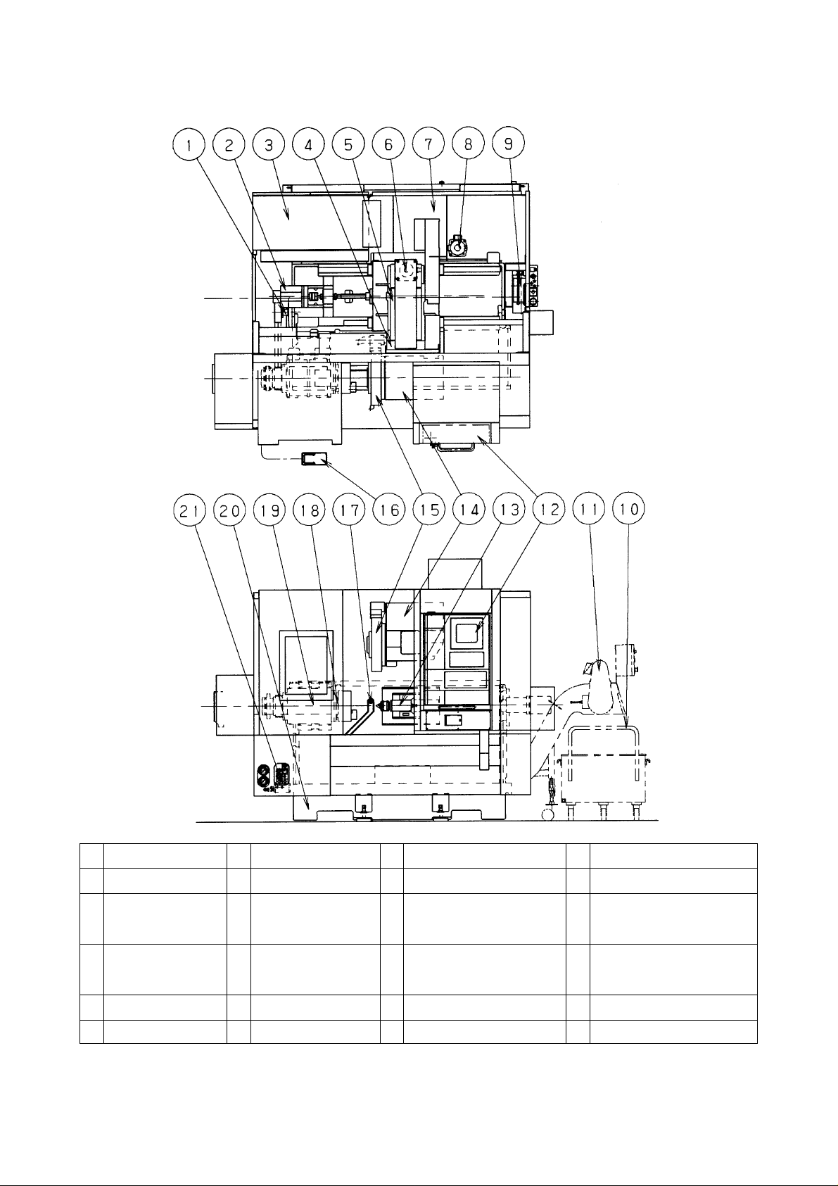
2-2 Component Units
1 Spindle motor 7 Coolant tank 13 Tailstock 19 Headstock
2 Z axis feed motor 8 Coolant pump 14 Tool post 20 Bed
3 High voltage 9 Oil pressure unit 15 Turret 21 Chuck/tailstock pressure
distribution board adjustment manifold
4 Cross slide 10 Chip box (OP) 16 Foot switch for chuck
opening/closing
5 Saddle 1 1 Chip conveyor (OP) 17 Q setter
6 X axis feed motor 12 Operating panel 18 Spindle
2 - 2
Page 13

2-3 Machine Specifications
1) Machine Specifications
Specifications
Capacity Swing over bed mm 680
Chuck outer diameter mm 500
Max. machining diameter mm 220 254
Max. machining length mm 490 470
Bar capacity mm 70 80
Stroke X axis mm 260
Z axis mm 520
Spindle Spindle speed min
Spindle speed range Step Infinite
Spindle nose (Type, No.) JIS A2-6 A2-8
Diameter of spindle through hole mm 80 95
Spindle bearing inside diameter mm 120 140
Turret Type of turret 12 station variable
head No. of tool position pcs. 12
Shank height of square bite mm 25
Unit
HT200/ST200
-1
50~5000 42~4200
Standard Specification
HT250/ST250
Shank diameter of boring bar mm 40 (B/H hole dia. 50)
Feedrate Rapid traverse X axis m/min 40
Z axis m/min 40
Cutting feedrate (Per revolution) mm/rev 0.001~1000
Jog feed mm/min 0~5000
Tailstock *1 Stroke of t ailstock mm 550
Type of tailstock spindle taper hole MT-5
Method of tailstock travel Power operation
Motor For spindle motor
(50%ED/continuous)
Axis feed motor X axis AC-KW 2.9
For turret indexing AC-KW 1.3
For Toilstock W 150
Oil pressure pump W 400
For cutting and chip washing W 180
Power
source
Power supply KV A 15 18
Z axis AC-KW 2.9
AC-KW 12/6 18.5/6
Machine
weight
*1 The system is structured in such a way that by operating command, the tailstock moves forward, back
ward and in forward inching mode within the whole range of the stroke.
Kg 4850 4950
2 - 3
Page 14

2) Main Accessories
Standard Accessories
Hyd’ hollow chuck (HT200/ST200 : φ220, HT250/ST250 : φ254)
Soft jaw
One-touch tailstock (Tailstock)
Q-setter
Flood coolant (Chip wash coolant)
Splash cover
Operator side door interlock
Spindle speed meter on screen
Spindle load meter on screen
Spindle/feedrate override
Call light (Std. Yellow)
Electric leakage detection breaker
Machining completion pre-call/Work counter/
Run hour display on screen
Work light
Leveling block
Spanners and wrenches
Chuck op. By M-code
Tailstock op. By M-code
2 - 4
Page 15

Optional Accessories
1. NC tailstock
2. C-axis control
3. X-axis scale feedback
4. 12 st. QCT(KV) turret
5. 12 st. VDI turret
6. 12 st. VDI rotating tool turret
7. Builtin type tailstock
8. Chip conveyor, Right / Rear type
Flat / Scrape with Roring filter / Magnet
scrape
9. Chip conveyor with intermittent feed
10.Chip wagon with roller
11. Jet coolant
12.Gun coolant
13.Chuck overhead coolant
14.Mist collector
15.Collet chuck
16.Chuck open/close confirmation
17.High/low 2-step pressure chucking
21.Spindle positioning dev., 1 position, electric
22.Auto door
23.Bar feeder
24.Bar puller
25.Parts catcher
26.Spindle end coolant collector for bar feed att.
27.Separate type spindle speed meter
28.Separate type counter A/B/C
29.Additional call light
30.Automatic power cut-off device
31.Separated start/stop/emergency button
32.Separated start/stop button
33.Z setter
34.Auto presetter & Q-setter, tool breakage
detection
35.Inside machine work measuring equipment
For Chuck work (X/Z) / Center work (X)
36.Transformer 45KVA
37.Preliminarily E/L application
18.Tailstock operation by foot pedal
19.Inside spindle work stopper
20.Face driver anti-powerfailure
* The contents of accessories and equipment are subject to change without notice. Please
contact the sales department of Hitachi whenever you have any inquiry for answer.
2 - 5
Page 16

2-4 NC Unit Specifications
Refer to the NC unit specifications list of SEIKI SEICOS instruction manual (operation section) for
details of specifications.
Item Standard specification
1 Controlled axis 2 axes, 2 axes simultaneous
2 Least input increment 0.001mm/0.0001’’
3 Interpolation Positioning, Linear, Circular
4 Inch/Metric conversion
5 Tape code EIA/ISO auto.recognition
6 Designation INC./ABS.
7 Decimal point programming
8 Buffer register
9 Feedrate command F code/feedrate direct
10 Rapid traverse override 0, 1, 10, 50, 100%
11 Feedrate override 0~200%
12 Spindle override 50~150% (10% step)
13 Threading function F/E code direct
14 Manual feed function Rapid, Jog feed, Handle
15 Manual pulse generator ×1, ×10, ×100 (inch=×50)
16 Part program storage 1000m/1 directory Total 1000m(1000m × 10 directories)
17 Add. registered programs 100 pcs./1 directory Total 1000pcs.
(100pcs. × 10 directories)
18 Back ground editing
19 Extended program edit (Program copy)
20 Display 10.4" color TFT
21 Memory lock
22 Language display English/German
23 I/O interface RS232C*
24 I/O interface PC card (PCMCIA I/F)
25 Function G3, M3, T4, O8 digits
26 Spindle speed command S code/speed direct
27 Constant surface speed control
28 Automatic tool nose radius
compensation
29 Grooving width offset (ID, OD, Face)
30 Tool offsets 32 sets
31 Q-setter repeat function
32 Cutting point coordinate system
setting
33 Reference point return Manual, Auto G28
34 2nd reference point return G30
35 Graphic display Before and synchronized machining
1
2 - 6
Page 17

Item Standard specification
36 Program comment 16-character
37 Single block
38 Block skip 1 pc.
39 Optional stop
40 Program check function Dry run + Spindle stop + coolant stop
41 Machine lock
42 Program number search
43 Sequence number search,
44 Program comparison
45 Manual absolute [ON] fixed
46 Flexi macro Common variable 100 pcs.
47 Soft jaws forming function (by graphic)
48 Fixed cycle G90, G92, G94
49 Multiple repetitive cycle G70~G76
50 Mirror image G501 G511
51 Radius designation on arc
52 Exact stop G09 G61 G64
53 Programmable data input G10
54 Backlash compensation
55 Run hour display/Spindle ( On screen)
speed display
56 Cycle completion pre-call / (On sxreen)
Cycle time display /
Work counter
57 Following up
58 NC flight recorder
59 Stored stroke limit 1.2.3
60 Strock check before move
61 NC self diagnostics
62 Customizing screen
63 User screen
*1 Interface only.
Not include cable.
2 - 7
Page 18

Item Optional specification
1 Direct tapping (Rotating tool)
2 Variable lead threading
3 Thread cutting cycle retract
4 Multiple start thread cutting
5 Flexi macro Common variable 200 pcs.
6 Flexi macro Common variable 300 pcs
7 Flexi macro Common variable 600 pcs.
8 Drilling cycle (Incl. in rotating tool) G80~89
9 Cutting doubler
10 Spindle positioning (Minimum inc. 0.001°)
11 Macro print function (Need printer w/ RS232C I/F) *1
12 Part program storage Total 100000m (1000m
× 100 directory)
Add. registered programs Total 10000 pcs. (100 pcs. × 100 directory)
13 Tool diameter compensation (Rotating tool)
14 Tool offsets Total 64 pcs.
15 Tool offsets Total 99 pcs.
16 Tool offsets Total 200 pcs.
17 3rd-4th reference point return
18 Program comment 64-character
19 Block skip Total 8 pcs.
20 Angle program for linear interpolation
21 Cylindrical interpolation (Incl. tool diameter compensation)
22 Polar coordinate interpolation (Incl. tool diameter compensation)
23 I/O interface RS232C 2ch
24 UUP (Universal user port)
25 Tool life management/Spare tool call
26 Each program, cycle time display 10pcs.(On screen)
27 Each program, cycle time display 50pcs.(On screen)
28 Cutting monitor (Incl. tool life management (Count only)/Spare
tool call)
29 NC chuck function (Incl. with NC chuck option)
30 NC tailstock function (Incl. with NC tailstock option)
31 C-axis control
32 Super multi interactive system 3D-simulation
Shape input method List & symbol input
Automatic determination Machining method/ mashining area/
function Process/ T ool/
Tool position/ Cutting condition/
Tool path interference/ Tool path
Automatic process Turning process: 21 process
Machining process: 8 process
2 - 8
Page 19

Item Optional specification
Automatic program NC data/ Tool/
Position of tool/ Cycle time
Dynamic graphics Automatic graphics
Editing Confirmation method/
NC data editing
Data saving/ Input, output NC data/ Shape data/
I/O to NC machine
*1 Interface only.
Not include cable.
2 - 9
Page 20
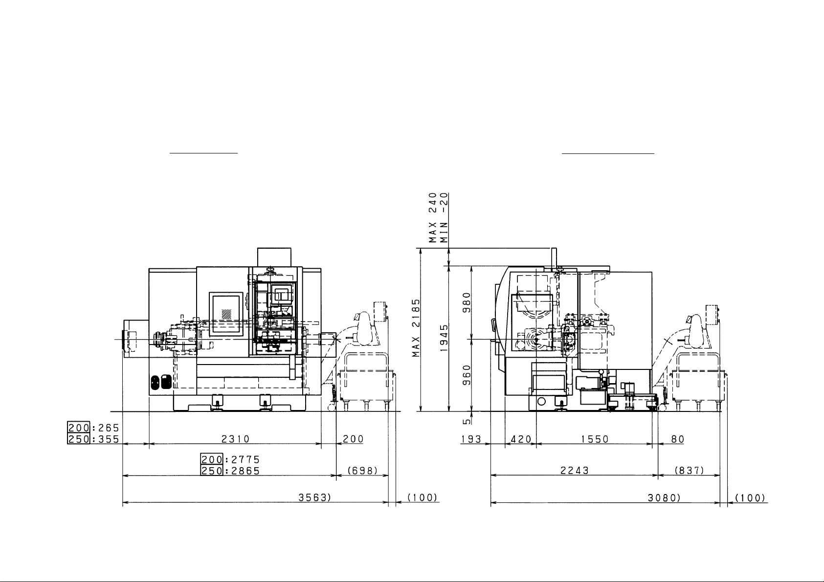
2-5 Major Dimensions
1) Major Dimension
Dimension: metric (mm)
inch ( ” )
2 - 10
FRONT VIEW
(90.9”)
Right side type
chip conveyor
(option)
Chip
wagon
(option)
(7.8”)
RIGHT SIDE VIEW
(0.7”)
(9.4” )
Rear side type
chip conveyor
(option)
(38.5”)
(86.0” )
(76.5”)
Chip
(37.7”)
(0.2”)
wagon
(option)
(109.2”)
(1 12.7”)
( Right side type chip conveyor spc.
(27.5”)
(7.5”) (16.5”)
( Rear side type chip conveyor spc.
(61.0”) (3.1”)
(88.3”)
(32.9”)
(121.2”)(3.9”)(140.2”)
(3.9”)
Page 21
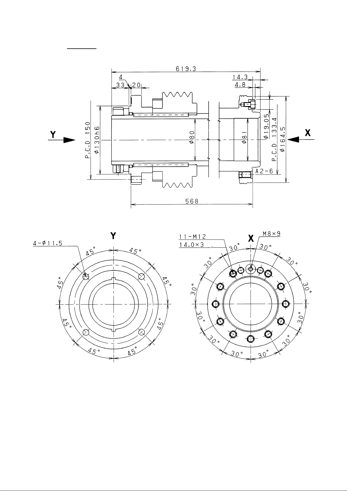
2) S pindle
HT/ST200
Dimension: metric (mm)
inch ( ” )
Eyehole
(0.1”)
(0.7”)
(1.2”)
(5.9”)
(5.1”)
(24.3”)
(3.1”)
(22.3”)
(Inlet)
(0.5”)
(0.1”)
(0.7”)
(5.2”)
(6.4”)
(3.1”)
2 - 11
Page 22
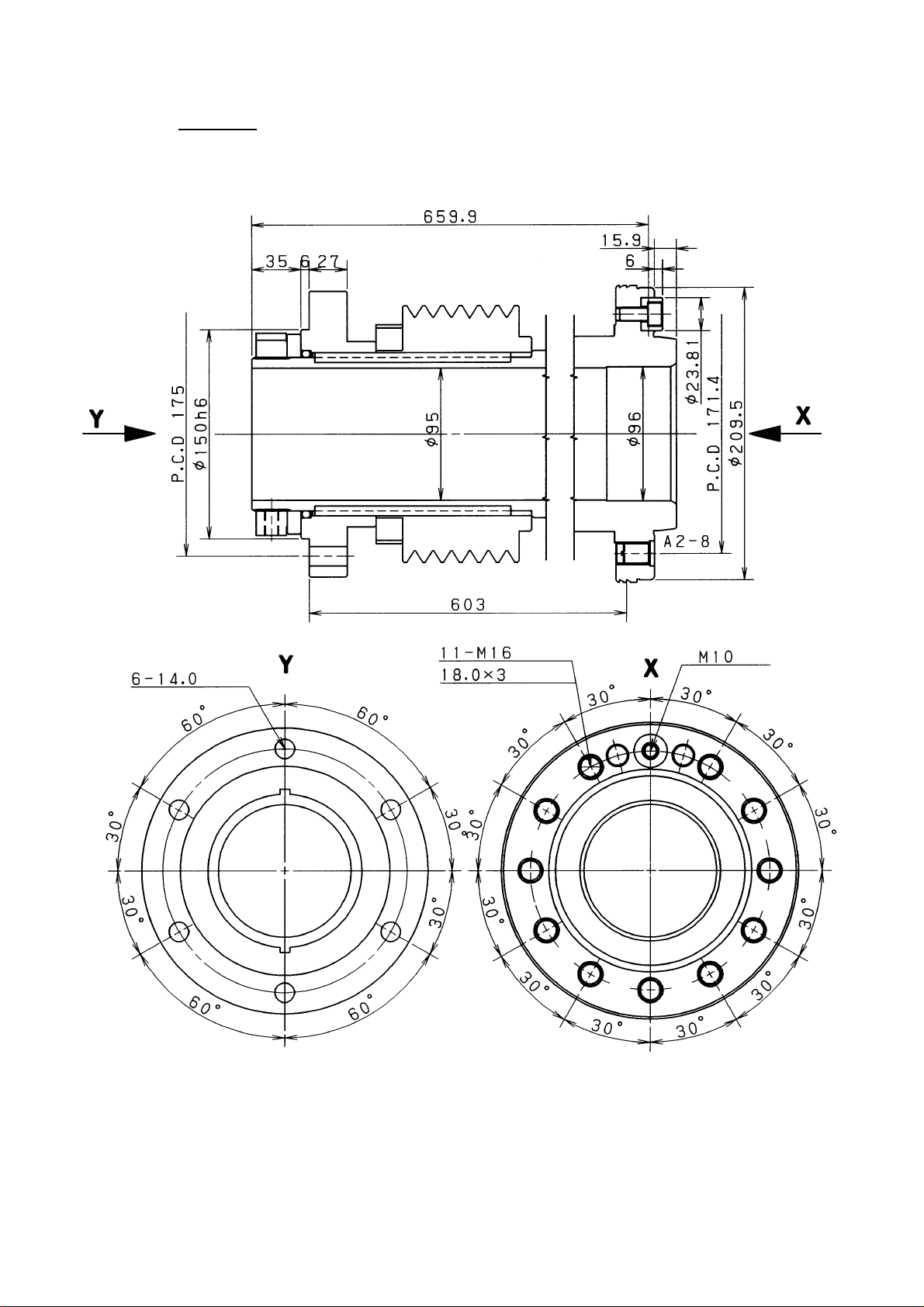
HT/ST250
Dimension: metric (mm)
inch ( ” )
(6.8”)
(5.9”)
Eyehole
(1.3”)
(0.2”)
(1.0”)
(25.9”)
(3.7”)
(23.7”)
(Inlet)
Eyehole
(0.6”)
(0.2”)
(0.9”)
(6.7”)
(8.2”)
(3.7”)
Eyehole
2 - 12
Page 23

3) Tool Post List
No. Tool post
1 12-station Base Holder
2 12-st ation QCT(KV)
3 12-station VDI
4 12-station VDI rotaring tool
2 - 13
Page 24

4) 12-station Base holder turret
(3.7”)
(0.5”)
(3.3”)
(2.1”)
(0.5”)
(1.8”)
(2.0”)
(8.8”)
(1.8”)
(0.9”)
(17.7”)
(0.5”)
(3.3”)
(2.1”)
(0.5”)
(8.8”)
(1.8”)
(3.7”)
(1.8”)
Dimension: metric (mm)
inch ( ” )
Note 1)
(1.0”)
Turret
(0.9”)
(0.4”)
(0.4”)
(0.4”)
(0.2”)
(0.2”)
(2.3”)
(1.6”)
(3.3”)
(0.4”)
(0.9”)
(1.6”)
(0.5”)
Piece
Fixture screw
Hexagon socket head
cap screw M8×25
Note 1) For reverse turn cutting, use 0.8mm spacer for re
verse turn cutting (2 pieces standard accessory)
2 - 14
Page 25

5) Base Holder
Base holder for boring
(1.5”)(0.1”) (3.5”)
(1.9”)
(1.6”)
(0.9”)
(0.6”)
Base holder for U drilling
(4.6”)
(0.9”)
(0.1”)
(3.3”)
(0.9”)
(4.4”)
Dimension: metric (mm)
inch ( ” )
(3.5”) (1.5”)
(0.1”)
(1.6”)
(0.9”)
(0.6”)
(4.6”)
(0.9”)
(1.5”)
(0.1”)
(3.3”)
(0.5”)
(4.1”)
2 - 15
Page 26

Base holder for end face grooving
(1.3”) (1.3”) (0.9”) (0.9”)
Dimension: metric (mm)
inch ( ” )
(2.1”)
(2.3”)
(0.1”)
(0.9”)
(1.1”)
(1.8”)
(0.9”)
(1.8”)
(4.6”)
(1.1”)
(1.1”)
(0.1”)
(3.5”)
(3.7”)
2 - 16
Page 27

6) 12-station QCT(KV) tool turret head
(17.7”)
Dimension: metric (mm)
inch ( ” )
(20.6”)
2 - 17
Page 28

7) 12-station VDI tool turret / 12-station VDI rotating tool turret
Dimension: metric (mm)
inch ( ” )
Holder positioning for key
Holder positioning for pin
(16.1”)
(18.8”)
(0.5”)
(0.5”)
(1.8”)
(0.5”)
(1.2”)
(8.0”) (8.0”)
2 - 18
Page 29

Base holder for OD cutting
Dimension: metric (mm)
inch ( ” )
(1.0”)
(1.6”)
(3.3”)
(0.6”)
(1.2”)
(3.1”)
(0.9”)
(2.7”)
(1.5”)
(5.2”)
(0.9)
(0.3”)
2 - 19
Page 30

Base holder for boring
Dimension: metric (mm)
inch ( ” )
(2.9”)
(2.1”)
(3.2”)
(1.2”)
(0.4”)
(0.8”)
(5.4”)
(1.5”)
2 - 20
Page 31

offset Base holder for boring
Dimension: metric (mm)
inch ( ” )
(2.9”)
(2.3”)
(1.5”)
(6.2”)
(2.9”)
(1.2”)
(3.1”)
(1.5”)
(0.6”)
(0.8”)
(5.4”)
2 - 21
Page 32

X-axis rotating tool base holder
Dimension: metric (mm)
inch ( ” )
(3.3”)
(1.7”)
(0.8”)
(3.2”)
Z-axis rotating tool base holder
(2.4”)
(4.1”)
(2.0”)
(5.8”)
(1.5”)
(0.8”)
(1.5”)
(2.4”)(1.6”)
(3.2”)
(4.7”)
2 - 22
Page 33

8) Chuck
HT/ST200 φ220chuck
(4.2”)
(5.8”)
(1.6”)
Dimension: metric (mm)
inch ( ” )
M2×32
Hexagon socket
head cap screw
(2.8”)
(4.1”)
(5.2”)
M12
×22
Hexagon socket
head cap screw
Hanging hole 2 pcs. -M10
(0.7”)
(1.3”)
(0.5”)
(0.9”)
(1.3”)
(0.7”)
(3.1”)
(8.6”)
(0.5”)
(2.2”)
(0.5”)
(0.5”)
(1.3”)
Soft jaw
9001-65-007-**
(1.5”)
(0.9”)
Detailed serration
2 - 23
Page 34

HT/ST250 φ254 chuck
(6.7”)
Dimension: metric (mm)
(6.8”)
(4.9”)
(1.9”)
(5.5”)
(3.2”)
inch ( ” )
M2×32
Hexagon socket
head cap screw
(0.8”)
(1.2”)
(0.3”)
M16
×30
Hexagon socket
head cap screw
(0.8”)
(1.5”)
(1.5”)
(4.4”)
Hanging hole 2 pcs. -M10
(0.5”)
(0.7”)
(3.4”)
(1.2”)
(0.6”)
(1.6”)
Soft jaw
9001-65-012-**
(1.8”)
Detailed serration
2 - 24
Page 35

(2.9”)
9) Hollow chuck cylinder
Connecting part for φ220 hollow chuck cylinder
2 - 25
Cylinder
ZKP150/72-17-17
MATSUMOTO
(22.3”)
(0.1”)
(6.4”)
(4.9”)
(5.9”)
(5.1”)
(3.1”)
(3.1”)
(1.9”)
(2.8”)
(4.2”)
Cylinder stroke
(0.6”)
(27.7”)
(1.5”)(4.3”)
Hollow chuck
ZA6-8-72B-05
MATSUMOTO
(8.6”)
(2.8”)
Dimension: metric (mm)
inch ( ” )
No. Name Drawing No. or type Q’ty
1 Bolt with hexagonal hole 4B1060 4
2 Tube and adapter 1782-00-816-** 1
3 Bolt with 6B1030 4
4 Nut 1N10 4
Page 36

(3.2”)
(23.7”)
(5.0”)
Connecting part for φ254 hollow chuck cylinder
(1.8”)
2 - 26
Cylinder
ZKP170/82-20-16
MATSUMOTO
(3.7”)
(0.7”)
(3.5”)
(2.2”)
(3.2”)
(4.9”)
Hollow chuck
ZAB-10-82B-02
MATSUMOTO
(10.0”)
(3.2”)
Dimension: metric (mm)
inch ( ” )
(0.2”)
(7.2”)
(6.8”)
(4.9”)
(5.9”)
Cylinder stroke
Cylinder stroke
(29.5”)
No. Name Drawing No. or type Q’ty
1 Bolt with hexagonal hole 4B1060 4
2 Tube and adapter 1782-00-819-** 1
3 Bolt with 6B1240 4
4 Nut 1N12 4
Page 37

10) Center
Tailstock Center
Dimension: metric (mm)
inch ( ” )
(1.7”)
(3.3”)
(0.6”)
2 - 27
Page 38

3. REQUIRED DIMENSION FOR MACHINE
3-1 Tool Traveling Range
Dimension : metric (mm)
inch ( ” )
1) HT200/250, ST200/250
12-station Base Holder Turret Head
O.D turning tool
I.D turning tool
(1.4”)
(1.4”)
(2.2”)
(2.3”)
(4.7”)
(8.7”)
(4.2”)
(4.9”)
(10.0”)
(9.8”)
(1.7”)
(2.0”)
(20.5”)
(20.5”)
(0.4”)
Upper : HT/ST200
Lower : HT/ST250
(0.3”)
(1.4”)
(10.2”)
(3.9”)
(0.2”)
Tailstock
(5.5”)
(5.4”)
(7.7”)
(10.2”)
(2.6”)
(4.6”)
(21.6”)
3 - 1
Page 39

2) 12-station QCT(KV) Tool Turret Head Dimension : metric (mm)
inch ( ” )
Upper : HT/ST200
Lower : HT/ST250
O.D turning tool
(0.3”)
(4.7”)
(20.5”)
(2.1”)
O.D tool
(1.4”)
(1.4”)
I.D turning tool
(4.9”)
(3.3”)
(8.7”)
(4.2”)
(10.0”)
(7.1”)
(10.2”)
(1.7”)
(2.0”)
(20.5”)
(3.1”)
(0.6”)
(3.0”)(2.3”)(0.9”)
(0.3”)
I.D tool
(9.4”)
(10.2”)
(3.1”)
Tailstock
(5.5”)
(5.4”)
(0.8”)
(21.6”)
(0.6”)
(4.6”)
3 - 2
Page 40

3) 12-station VDI Turret Head
O.D turning tool
(4.7”) (20.5”)
Dimension : metric (mm)
inch ( ” )
Upper : HT/ST200
Lower : HT/ST250
(0.3”)
(2.8”)
(1.4”)
(1.4”)
I.D turning tool
(3.3”)
(8.7”)
(4.2”)
(4.9”)
(10.2”)
(7.1”)
(2.8”)
(1.7”)
(2.0”)
(20.5”)
(10.2”)
(0.6”)
(3.0”)(2.3”)
(2.8”)
(0.8”)
(0.3”)
(10.0”)
Tailstock
(5.5”)
(5.4”)
(0.8”)
(21.6”)
3 - 3
(0.6”)
(3.5”)
(4.6”)
Page 41

4) 12-station VDI Rotating Tool Turret Head Dimension : metric (mm)
inch ( ” )
Upper : HT/ST200
Lower : HT/ST250
O.D turning tool
(1.4”)
(1.4”)
I.D turning tool
(4.7”) (20.5”)
(8.7”)
(10.0”)
(4.2”)
(4.9”)
(3.3”)
(20.5”)
(7.5”)
(2.8”)
(1.7”)
(2.0”)
(10.2”)
(4.7”)
(3.5”)
(1.6”)
(0.3”)
(4.7”)
(3.0”)
(10.2”)
(4.7”)
(3.5”)
(1.6”)
(0.3”)
(4.7”)
3 - 4
Page 42

Dimension : metric (mm)
inch ( ” )
X axis rotating tool
Upper : HT/ST200
Lower : HT/ST250
(4.7”) (20.5”)
(1.4”)
(1.4”)
Z axis rotating tool
(3.3”)
(8.7”)
(4.2”)
(4.9”)
(10.2”)
(7.1”)
(2.8”)
(1.7”)
(2.0”)
(20.5”)
(4.7”)
(10.2”)
(4.1”)
(3.0”)
(0.6”)
(3.5”) (4.7”)
(3.2”)
(10.0”)
Tailstock
(5.5”)
(5.4”)
(21.6”)
3 - 5
(3.9”)
(7.1”)
(4.6”)
Page 43

3-2 Tool Interaction Drawing
1) 12-station Base Holder Turret Head
a) Limit of the machining area by the turret
(24.8”)
(8.9”)(9.8”)
(10.2”)
(3.5”)
Dimension : metric (mm)
inch (
Max swing
(4.3”)(5.9”)
(10.0”)
” )
(28.3”)
(0.5”)
(1.4”)
(10.2”)
X-axis stroke
(0.4”)
(1.6”)
(10.0”)
(7.7”)
(2.6”)
(0.3”)
(1.6”)
(10.0”)
(0.2”)
(0.4”)
(0.4”)
(1.0”)
Max. machining
diameter
(19.7”)
(1.4”)
(1.4”)
(4.2”)
(4.9”)
(1.7”)
(2.0”)
(4.7”)
(1.4”)
Z-axis stroke
minus end
Standard
projecting
amount
3 - 6
(2.2”)
(2.3”)
(3.9”)
Standard
projecting
amount
Z-axis stroke
minus end
Page 44

b) Limit of the machining area when Hitachi Seiki revolving center is used.
Outer diameter roughing tool
(0.3”)
Standard projecting
amount
(1.4”)
(1.6”)
(1.6”)
(3.0”)
(1.0”)
Dimension : metric (mm)
inch (
” )
Outer diameter profiling tool
(The tool is 10mm (0.4”) projection than the standard)
(0.3”)
(1.0”)
(0.2”)
(1.8”)
(3.0”)
(1.6”)
3 - 7
Page 45

2) 12-station QCT(KV) Turret Head
a) Limit of the machining area by turret
Dimension : metric (mm)
(7.5”)
(0.8”)
inch (
(0.08”)
” )
(8.9”)
(1.7”)
(2.4”)
(7.1”)
(10.2”)
X-axis stroke
(3.1”)
Max. swing
(17.7”)
(1.3”)
(28.3”)
(0.05”)
(1.6”)
(0.1”)
(0.7”)
Max. machining
(14.2”)
(10.0”)
dameter
3 - 8
Page 46

3) 12-station VDI Turret Head / VDI Rotating Tool Turret Head
a) Limit of the machining area by turret
I.D offset holder for STW
Dimension : metric (mm)
inch (
” )
O.D profiling
X-axis rotating tool
for NR
(8.1”)
(2.8”)
(10.0”)
I.D offset holder for NR
(0.8”)
(8.9”)
(0.8”)
(1.4”)
(3.0”)
(3.9”)
(2.9”)
(0.09”)
(0.2”)
(0.1”)
(3.9”)
(6.9”)
(16.1”)
Max. swing
(2.9”)
(3.2”)
(0.2”)
X-axis rotating tool for HT/ST
(28.3”)
(1.3”)
(1.7”)
(0.5”)
(3.9”)
(2.2”)
(0.07”)
(0.8”)
(0.2”)
(10.2”)
(7.5”)
X-axis stroke
(2.8”)
(1.1”)
Max. machining
(10.0”)
(15.0”)
dameter
3 - 9
Page 47

3-3 Quick Setter and Workpiece Interference Drawing
φ220 chuck
(0.8”) (0.8”)
(5.9”)
(0.8”)
(0.4”)
(0.8”) (0.8”)
(4.2”)
(8.7”)
(1.7”)
(14.2”)
(11.9”)
(9.7”)
(3.0”)
(7.4”)
(5.2”)
(1.6”)
(10.0”)
(1.8”)
(0.2”)
(10.8”)
(1.3”)
3 - 10
Page 48

φ254 chuck
(5.7”) (0.8”) (0.8”) (0.8”)
(0.8”) (0.8”)
(4.9”)
(10.0”)
(2.0”)
(14.2”)
(11.9”)
(9.7”)
(7.4”)
(5.2”)
(0.4”)
(3.0”)
(1.6”)
(10.0”)
(1.8”)
(0.2”)
(10.8”)
(1.3”)
3 - 11
Page 49

3-4 Spindle Output Diagram
This machine is equipped with a variable AC motor. The output within the constant torque
varies with the number of the spindle revolutions at that moment.
When heavy cutting (roughing and so forth) is done within the constant torque area, depending
on the spindle revolution speed, it may come to a stop being unable to withstand the cutting
force.
Accordingly, select the revolution speed area in such a way that heavy cutting is done within
the output constant area.
HT/ST200
(CONT)
Low speed wire winding
Low speed wire winding (CONT)
High speed wire winding
High speed wire winding (CONT)
Spindle Speed [min
-1
(rpm)]
3 - 12
Page 50

HT/ST250
Low speed wire winding
High speed wire winding
Low speed wire winding (CONT)
(CONT)
High speed wire winding (CONT)
Spindle Speed [min-1 (rpm)]
3 - 13
Page 51

Spindle Output Diagram(Builtin motor C-axis specifications)
POWER
HT/ST200
M40 Within the constant torque
CONT)
M41 Within the constant torque
TORQUE
(CONT)
POWER
Spindle Speed [min-1 (rpm)]
TORQUE
HT/ST250
CONT)
(CONT)
(CONT)
M40 Within the constant torque
M41 Within the constant torque
Spindle Speed [min
3 - 14
-1
(rpm)]
Page 52

Rotating Tool Spindle Output Diagram
TORQUE
POWER
minute)
minute)
Spindle Speed [min-1 (rpm)]
3 - 15
Page 53

3-5 Chucking Pressure-Gripping Force Diagram
HT/ST200
Chuck :ZA6-8-72B
Cylinder :ZKP150-72-17-17
Gripping force
Chucking pressure
HT/ST250
Chuck :ZA8-10-82B
Cylinder :ZKP170-82-20-16
Gripping force
Chucking pressure
3 - 16
Page 54

Chucking Pressure-Gripping Force Diagram
HT/ST200
Chuck : ZA6-8-72B
Gripping force
Gripping force
HT/ST250
Chuck : ZA8-10-82B
Revolution (min
-1
)
Revolution (min
3 - 17
-1
)
Page 55

3-6 Tailstock Pressure-Thrust Diagram
Relations between tailstock pressure and the thrust power are as shown in the diagram
below. A pressusre adjusting valve is located on the left side of the machine.
Tailstock pressure adjustment should be made under the condition where a workpiece is
being chucked and pushed by the tailstock.
Thrust
Pressure
As a guidance, for material
φ100×300......S45C
or equivalent, the value of thrust is about 200kgf.
When used below the set pressure 1MPa(10 kgf/cm
tailstock is lowered.
2
, 142 lbs/in2), moving speed of the
3 - 18
Page 56

3-7 Method of Obtaining Tool Center Height
The height of the outside diameter tool is 25mm on the base holder turret head.
On the VDI rotating tool turret head, the hight is 20mm.
Base Holder turret : BH
VDI rotating tool turret : VDI
Dimension : metric (mm)
inch (
” )
BH : 32.0 (1 3/4”)
VDI : 25.0 (1”)
BH : 150 (6”)
VDI : 125 (5”)
BH : 25.0 (1”)
VDI : 20.0 (3/4”)
BH : 25.0 (1”)
VDI : 20.0 (3/4”)
BH : 25.0 (1”)
VDI : 20.0 (3/4”)
1. When center height must be adjusted with O.D. tools, make adjustment of height, putting
a spacer; etc.
Block
BH : 25.0 (1”)
VDI : 20.0 (3/4”)
place a wood sheet as necessary
Flat surface such as a surfave plate
Attach the tool to the support,after adjusting the heigh with 25mm block gauge outside
the machine
3 - 19
Page 57

4. TOOLING SYSTEM
4-1 12st. Base Holder Turret Head Combination Tool List (Standard)
4-1-1 HT/ST200
CI.
Chuck
Base
holder
1782-MC-101-00
1594-109-59-00
1594-109-60-00
1594-113-09-00
1782-40-009-00
Hydraulic power
chuck
(big bore type)
Power chuck
(Unit:1 set)
Cylinder
(Unit: 1 set)
Soft jaw
Base holder for
I.D. cutting
SKETCH DESCRIPTIONNAMEPARTS NO
Cylinder
Cylinder
H.S chuck
Connecting
tube
(1/1)
φ220 big bore chuck (A2-6)
Hollow cylinder
Soft jaw 1piece
φ220 big bore chuck
(MATUMOT O)
Bore ID. φ72
ZA6-8-72B-05
Hollow cylinder
(MATUMOT O)
ZKP150/72-17
Coolant recovery cover, Draw
tube, anti-turning stay
φ220 big bore chuck
3pieces set
OD
Tools
ID
Tools
1593-028-01-00
1596-347-15-00
1596-347-16-00
1596-347-17-00
1596-346-04-00
Spacer for the
reverse cutting
Boring bar socket
for φ40 shank
Boring bar socket
for φ32 shank
Boring bar socket
for φ25 shank
Boring bar socket
for φ20 shank
it is required when carrying out
reverse cutting of an O.D.
4 - 1
Page 58

4-1-2 HT/ST250
(1/1)
CI.
Chuck
Base
holder
OD
Tools
PARTS NO
1782-MC-103-00
1594-109-64-00
1594-109-65-00
1594-113-01-00
1782-40-009-00
1593-028-01-00
Hydraulic power
chuck
(big bore type)
Power chuck
(Unit:1 set)
Cylinder
(Unit: 1 set)
Soft jaw
Base holder for
I.D. cutting
Spacer for the
reverse cutting
SKETCH DESCRIPTIONNAME
Cylinder
Cylinder
H.S chuck
Connecting
tube
φ254 big bore chuck (A2-8)
Hollow cylinder
Soft jaw 1piece
φ254 big bore chuck
(MATUMOTO)
Bore ID. φ82
ZA8-10-82B-02
Hollow cylinder
(MATUMOTO)
ZKP170/82-20
Coolant recovery cover, Draw
tube, anti-turning stay
φ254 big bore chuck
3pieces set
it is required when carrying out
reverse cutting of an O.D.
ID
Tools
1596-347-15-00
1596-347-16-00
1596-347-17-00
1596-346-04-00
Boring bar socket
for φ40 shank
Boring bar socket
for φ32 shank
Boring bar socket
for φ25 shank
Boring bar socket
for φ20 shank
4 - 2
Page 59

4-2 12st. Base HolderTurret Head Combination Tool List (Selection)
4-2-1 HT200/250, ST200/250
CI
Base
holder
ID
T ool
1782-40-011-00
1782-40-013-00
1596-346-05-00
1593-340-13-00
1593-340-14-10
Base holder for
U-drill
Base holder for
face grooving
Boring bar socket
for φ16 shank
Boring bar socket
for φ12 shank
Boring bar socket
for φ10 shank
(MT)
(1/2)
SKETCH DESCRIPTIONNAMEPARTS NO
Socket for φ32, 25, 20 1pc
each.
Can be used both for whistle
notch shank ISO shank
Drilling
Tools
1593-340-15-10
1596-337-04-00
1596-337-03-00
1596-337-02-00
1596-337-01-00
1594-337-03-00
Boring bar socket
for φ8 shank
MT No.4
Drill socket
MT No. 3
Drill socket
MT No. 2
Drill socket
MT No.1
Drill socket
MT4 × MT3
Drill sleeve
For φ32~φ50 Morse taper
shank drill
For φ23~φ32 Morse taper
shank drill
For φ14~φ23 Morse taper
shank drill
For φ14 or less Morse taper
shank drill
4 - 3
Page 60

(2/2)(MT)
CI
Drilling
Tools
Tap
holder
Others
PARTS NO
1594-337-04-00
1782-95-001-00
1782-95-002-00
1593-347-01-00
1593-347-0200~08
1593-419-01-00
MT2 × MT1
Drill sleeve
Socket for φ8
center drill
Socket for φ5
center drill
Tapper
Tap collet
Revolving bar
stopper
SKETCH DESCRIPTIONNAME
S32-Z12-87.5L (NIKKEN)
Need φ32 socket
ZMK12 Without torque limitter
M3,4,5,6,8,10,12,14,16
Rotation type bar stopper
Need socket φ32
Live
center
Special
Accessory
1594-340-03-20
Live center
Spanners and
wrenches
(With tool box)
LC5X-7W(NSK)
1. Grease gun, oiler, philips
screw-drivers (medium,
large), slotted screw-driver
2. Open end spanners 10×13,
14×17, 19×24, 27×30, 36×41
3. Simple spanner 22
4. Hexagonal bar wrenches
3, 4, 5, 6, 8, 10, 14
4 - 4
Page 61

(1/1)(INCH)
CI
Base
Holder
I.D tool
1782-40-010-00
1782-40-012-00
1782-40-014-00
1596-347-18-00
1596-347-19-00
1596-347-20-00
I.D holder
Oil-hole drill
holder
Face grooving
holder
Boring bar socket
1-1/2”
Boring bar socket
1-1/4”
Boring bar socket
1”
SKETCH DESCRIPTIONNAMEPARTS NO
Include φ1-1/4”, φ1”, φ3/4”
socket 1pc each.
For Kennametal “Drill-Fix
(DFT)”
Drill
tool
Live
center
1596-347-04-00
1596-347-05-00
1596-337-06-00
1594-340-03-20
Boring bar socket
3/4”
Boring bar socket
5/8”
Drill socket MT2
Live center
MT5 shank Max 5000min
LC5X-7W(NSK)
-1
4 - 5
Page 62

4-3 12st. QCT(KV) Turret Head Combination Tool List (Standard)
4-3-1 HT/ST200
CI.
Chuck 1782-MC-101-00
1594-109-59-00
1594-109-60-00
1594-113-09-00
Hydraulic power
chuck
(big bore type)
Power chuck
(Unit:1 set)
Cylinder
(Unit: 1 set)
Soft jaw
SKETCH DESCRIPTIONNAMEPARTS NO
Cylinder
Cylinder
H.S chuck
Connecting
tube
(1/1)
φ220 big bore chuck (A2-6)
Hollow cylinder
Soft jaw 1piece
φ220 big bore chuck
(MATUMOT O)
Bore ID. φ72
ZA6-8-72B-05
Hollow cylinder
(MATUMOT O)
ZKP150/72-17
Coolant recovery cover, Draw
tube, anti-turning stay
φ220 big bore chuck
3pieces set
4 - 6
Page 63

4-3-2 HT/ST250
(1/1)
CI.
Chuck 1782-MC-103-00
PARTS NO
1594-109-64-00
1594-109-65-00
1594-113-01-00
Hydraulic power
chuck
(big bore type)
Power chuck
(Unit:1 set)
Cylinder
(Unit: 1 set)
Soft jaw
SKETCH DESCRIPTIONNAME
Cylinder
Cylinder
H.S chuck
Connecting
tube
φ254 big bore chuck (A2-8)
Hollow cylinder
Soft jaw 1piece
φ254 big bore chuck
(MATUMOTO)
Bore ID. φ82
ZA8-10-82B-02
Hollow cylinder
(MATUMOTO)
ZKP170/82-20
Coolant recovery cover, Draw
tube, anti-turning stay
φ254 big bore chuck
3pieces set
4 - 7
Page 64

4-4 12st. QCT(KV) Turret Head Combination Tool List (Selection)
4-2-1 HT200/250, ST200/250
CI
Base
holder
ID
T ool
1593-352-01-00
1593-352-02-00
1593-352-03-00
1593-331-35-00
1593-667-20-00
1593-667-21-00
Base holder for
outer figure
cutting
Base holder for
outer figure
copying
Base holder for
face grooving
Base holder used
both I.D cutting
U-drill
Boring bar socket
for φ25 shank
Boring bar socket
for φ20 shank
(1/2)
(MT)
SKETCH DESCRIPTIONNAMEPARTS NO
QCT40-TA25
QCT40-TB25
QCT40-TC25
QCT40-SU32
Drilling
Tools
1593-667-22-00
1593-667-23-00
1593-667-24-00
1593-667-25-00
1593-337-09-00
1593-337-10-00
1593-337-43-00
1593-337-04-00
Boring bar socket
for φ16 shank
Boring bar socket
for φ12 shank
Boring bar socket
for φ10 shank
Boring bar socket
for φ8 shank
MT No. 3
Drill socket
MT No. 2
Drill socket
MT No. 1
Drill socket
MT2 × MT1
Drill sleeve
For φ23~φ32 Morse taper
shank drill
For φ14~φ23 Morse taper
shank drill
For φ14 or less Morse taper
shank drill
1593-342-01-00
Socket for U-drill
φ20, 25 1pc each set.
Can be used both for whistle
notch shank ISO shank
4 - 8
Page 65

(2/2)(MT)
CI
Drilling
Tools
Tap
holder
Others
Live
center
Special
Accessory
PARTS NO
1594-331-54-01
1594-331-55-01
1593-347-01-00
1593-347-0200~08
1593-419-01-00
1594-340-03-20
Socket for φ8
center drill
socket for φ5
center drill
Tapper
Tap collet
Revolving bar
stopper
Live center
Spanners and
wrenches
(With tool box)
SKETCH DESCRIPTIONNAME
S32-Z12-87.5L (NIKKEN)
Need φ32 socket
ZMK12 Without torque limitter
M3,4,5,6,8,10,12,14,16
Rotation type bar stopper
LC5X-7W(NSK)
1. Grease gun, oiler, philips
screw-drivers (medium,
large), slotted screw-driver
2. Open end spanners 10×13,
14×17, 19×24, 27×30, 36×41
3. Simple spanner 22
4. Hexagonal bar wrenches
3, 4, 5, 6, 8, 10, 14
4 - 9
Page 66

(1/1)(INCH)
CI
I.D Tool
Drill
tool
Live
center
PARTS NO
1596-347-20-00
1596-347-04-00
1596-347-05-00
1596-337-06-00
1594-340-03-20
Boring bar socket
1”
Boring bar socket
3/4”
Boring bar socket
5/8”
Drill socket MT2
Live center
SKETCH DESCRIPTIONNAME
MT5 shank Max 5000min
LC5X-7W(NSK)
-1
4 - 10
Page 67

4-5 12st. VDI Turret Head Combination Tool List (Standard)
4-5-1 HT/ST200
CI.
Chuck 1782-MC-101-00
1594-109-59-00
1594-109-60-00
1594-113-09-00
Hydraulic power
chuck
(big bore type)
Power chuck
(Unit:1 set)
Cylinder
(Unit: 1 set)
Soft jaw
SKETCH DESCRIPTIONNAMEPARTS NO
Cylinder
Cylinder
H.S chuck
Connecting
tube
(1/1)
φ220 big bore chuck (A2-6)
Hollow cylinder
Soft jaw 1piece
φ220 big bore chuck
(MATUMOT O)
Bore ID. φ72
ZA6-8-72B-05
Hollow cylinder
(MATUMOT O)
ZKP150/72-17
Coolant recovery cover, Draw
tube, anti-turning stay
φ220 big bore chuck
3pieces set
4 - 11
Page 68

4-5-2 HT/ST250
(1/1)
CI.
Chuck 1782-MC-103-00
PARTS NO
1594-109-64-00
1594-109-65-00
1594-113-01-00
Hydraulic power
chuck
(big bore type)
Power chuck
(Unit:1 set)
Cylinder
(Unit: 1 set)
Soft jaw
SKETCH DESCRIPTIONNAME
Cylinder
Cylinder
H.S chuck
Connecting
tube
φ254 big bore chuck (A2-8)
Hollow cylinder
Soft jaw 1piece
φ254 big bore chuck
(MATUMOTO)
Bore ID. φ82
ZA8-10-82B-02
Hollow cylinder
(MATUMOTO)
ZKP170/82-20
Coolant recovery cover, Draw
tube, anti-turning stay
φ254 big bore chuck
3pieces set
4 - 12
Page 69

4-6 12st. VDI Turret Head Combination Tool List (Selection)
4-6-1 HT200/250, ST200/250
CI
Base
holder
ID
T ool
1742-67-080-00
1742-67-086-00
1742-67-079-00
1742-67-081-00
1593-331-29-00
1742-68-006-10
1593-355-03-00
1593-667-20-00
Base holder for
O.D. cutting
Base holder for
face grooving
(Offset)
Base holder for
I.D. cutting
Base holder for
I.D. cutting
(Offset)
Base holder for
U-drill
Base holder for
cutting-off
Base holder for
plug
Boring bar socket
for φ25 shank
(1/2)
SKETCH DESCRIPTIONNAMEPARTS NO
1742-67-442-
1742-67-505-
1742-67-443-
1742-67-473-
1742-67-674-
1742-67-558-/1742-67-670-
1742-67-568-
Drilling
Tools
1593-667-21-00
1593-667-22-00
1593-667-23-00
1593-667-24-00
1593-667-25-00
1593-337-09-00
1593-337-10-00
Boring bar socket
for φ20 shank
Boring bar socket
for φ16 shank
Boring bar socket
for φ12 shank
Boring bar socket
for φ10 shank
Boring bar socket
for φ8 shank
MT No. 3
Drill socket
MT No. 2
Drill socket
For φ23~φ32 Morse taper
shank drill
For φ14~φ23 Morse taper
shank drill
4 - 13
Page 70

(2/2)
CI
Drilling
Tools
Tap
holder
Others
1593-337-43-00
1593-337-04-00
1593-342-01-00
1594-331-54-01
1594-331-55-01
1593-347-01-00
1593-347-0200~08
1593-419-01-00
MT No. 1
Drill socket
MT2×MT1
Drill sleeve
Socket for U-drill
Socket for φ8
center drill
Socket for φ5
center drill
Tapper
Tap collet
Revolving bar
stopper
SKETCH DESCRIPTIONNAMEPARTS NO
For φ14 or less Morse taper
shank drill
φ20, 25 1pc each set.
Can be used both for whistle
notch shank ISO shank
S32-Z12-87.5L (NIKKEN)
Need φ32 socket
ZMK12 Without torque limitter
M3,4,5,6,8,10,12,14,16
Rotation type bar stopper
Live
center
Special
Accessory
1594-340-03-20
Live center
Spanners and
wrenches
(With tool box)
LC5X-7W(NSK)
1. Grease gun, oiler, philips
screw-drivers (medium,
large), slotted screw-driver
2. Open end spanners 10×13,
14×17, 19×24, 27×30, 36×41
3. Simple spanner 22
4. Hexagonal bar wrenches
3, 4, 5, 6, 8, 10, 14
4 - 14
Page 71

4-7 12st.VDI Rotating Tool Turret Head Combination Tool List (Standard)
4-7-1 HT/ST200
CI.
Chuck 1782-MC-101-00
1594-109-59-00
1594-109-60-00
1594-113-09-00
Hydraulic power
chuck
(big bore type)
Power chuck
(Unit:1 set)
Cylinder
(Unit: 1 set)
Soft jaw
SKETCH DESCRIPTIONNAMEPARTS NO
Cylinder
Cylinder
H.S chuck
Connecting
tube
(1/1)
φ220 big bore chuck (A2-6)
Hollow cylinder
Soft jaw 1piece
φ220 big bore chuck
(MATUMOT O)
Bore ID. φ72
ZA6-8-72B-05
Hollow cylinder
(MATUMOT O)
ZKP150/72-17
Coolant recovery cover, Draw
tube, anti-turning stay
φ220 big bore chuck
3pieces set
4 - 15
Page 72

4-7-2 HT/ST250
(1/1)
CI.
Chuck 1782-MC-103-00
PARTS NO
1594-109-64-00
1594-109-65-00
1594-113-01-00
Hydraulic power
chuck
(big bore type)
Power chuck
(Unit:1 set)
Cylinder
(Unit: 1 set)
Soft jaw
SKETCH DESCRIPTIONNAME
Cylinder
Cylinder
H.S chuck
Connecting
tube
φ254 big bore chuck (A2-8)
Hollow cylinder
Soft jaw 1piece
φ254 big bore chuck
(MATUMOTO)
Bore ID. φ82
ZA8-10-82B-02
Hollow cylinder
(MATUMOTO)
ZKP170/82-20
Coolant recovery cover, Draw
tube, anti-turning stay
φ254 big bore chuck
3pieces set
4 - 16
Page 73

4-8 12st. VDI Rotating Tool Turret Head Combination Tool List (Selection)
4-8-1 HT200/250, ST200/250
CI
Base
holder
1742-67-080-00
1742-67-086-00
1742-67-079-00
1742-67-081-00
1593-331-29-00
1742-68-006-10
1782-67-007-00
Base hgolder for
O.D cutting
Base holder for
face grooving
(Offset)
Base holder for
I.D. cutting
Base holder for
I.D. cutting
(Offset)
Base holder for
U-drill
Base holder for
cutting-off
Base holder for
X-axis rotating
tool
(1/2)
SKETCH DESCRIPTIONNAMEPARTS NO
1742-67-442-
1742-67-505-
1742-67-443-
1742-67-473-
1742-67-674-
1742-67-558-/1742-67-670-
ID
T ool
1782-67-008-00
1593-355-03-00
1593-667-20-00
1593-667-21-00
1593-667-22-00
1593-667-23-00
1593-667-24-00
1593-667-25-00
Base holder for
Z-axis rotating
tool
Base holder for
plug
1742-67-568-
Boring bar socket
for φ25 shank
Boring bar socket
for φ20 shank
Boring bar socket
for φ16 shank
Boring bar socket
for φ12 shank
Boring bar socket
for φ10 shank
Boring bar socket
for φ8 shank
4 - 17
Page 74

(2/2)
CI
Drilling
Tools
Tap
holder
PARTS NO
1593-337-09-00
1593-337-10-00
1593-337-43-00
1593-337-04-00
1593-342-01-00
1594-331-54-01
1594-331-55-01
1593-347-01-00
MT No. 3
Drill socket
MT No. 2
Drill socket
MT No. 1
Drill socket
MT2 × MT1
Drill sleeve
Socket for U-drill
Socket for φ8
center drill
Socket for φ5
center drill
Tapper
SKETCH DESCRIPTIONNAME
For φ23~φ32 Morse taper
shank drill
For φ14~φ23 Morse taper
shank drill
For φ14 or less Morse taper
shank drill
φ20, 25 1pc each set.
Can be used both for whistle
notch shank ISO shank
S32-Z12-87.5L (NIKKEN)
Need φ32 socket
Rotating
Tools
Others
Live
center
Special
Accessory
1593-347-0200~08
1596-352-1100~14
1596-352-0000~05
1593-419-01-00
1594-340-03-20
Tap collet
Collet
Tap collet
Revolving bar
stopper
Live center
Spanners and
wrenches
(With tool box)
ZMK12 Without torque limitter
M3,4,5,6,8,10,12,14,16
ESX32
(D=2.5, 3 ~ 16)
ET32
(M3, 4, 5, 6, 8, 10, 12)
Rotation type ber stopper
LC5X-7W(NSK)
1. Grease gun, oiler, philips
screw-drivers (medium,
large), slotted screw-driver
2. Open end spanners 10×13,
14×17, 19×24, 27×30, 36×41
3. Simple spanner 22
4. Hexagonal bar wrenches
3, 4, 5, 6, 8, 10, 14
4 - 18
Page 75

TURNING CENTER
HT200/250, ST200/250
INSTRUCTION MANUAL
SPECFICATION
SEICOS-pcFLexi
Version 1.01
10-2001
10-2001 First Edition
 Loading...