

hitachi seiki MICON 8 Maintenance Manual

HITACHI
SEIKI
MICON
8
MAINTENANCE
*
I
*=
4figl
\>
i
:
i
jPL;j
-
MANUAL
tL«
„
i
M-
MORI
THE
MACHINE
June.
2000-1
.;1
m
SEIKI
TOOL
COMPANY
Edition
st
1
i
r1
5
i
T
r


MICON
1
.
Specification
2.
TYPE-1-
8
(
CODE-XX
CONTENTS
1
).
1
-
2-1
3.
Construction
4.
Software
4-1.
4-2.
5.
Hardware
5-1.
5-2.
1.4
Board
Program
Interpreter
Timer
Key
A,
D/A
Machine
List
Flow
Example
Example
Control
4.1.1
4.1.2
4.1.3
4.
4.1.5
4.1.6
Sequence
4.2.1
4.2.2
4.2.3
4.2.4
Signal
CPU
Control
Board
B
Phase
Converter
Function
Program
Instructions
of
Chart
of
of
Control
Control
Control.
Instructions
Symbol
Flow
a
Chart.
3-1
4-1
4-1
4-1
4-2
4-2
4-2
4-2
4-2
4-3
3
4
~
-
4
5
~
-
4-8
4-9-4-10
5-1
-5-2
5-1
5-3
4-4
4
-
7
6.
7.
5-3.
Architecture
5.3.1
5.3.2
5.3.3
5.3.4
5.3.5
Keyboard
.
6-1
Keys
6-2.
Display
6-3.
How
6-4.
How
6-5.
MICON
Main
Board
General
Memory
Input
Output
Key
and
and
to
Identify
Identify
to
Replacement
(
Display
&
Display
Their
Pattern
Operation
8
Included
Operation
Uses
Indication
Alarm
Individual
sheet
Procedure
Digital
Signals.
(
to
Analog
Converter)
PT-CODE-xx
5-4
5-4
5
5
5
-
6
-
-
5-7-5-11
5-12-5-24
5-25
6-1
6-1
6-2
6-3
6-4-6-12
6-13
)
7-1

.
1
MICON
8
TYPE-II-
(
SQM8-XX
•
1
)
-1
2.
Specification
3.
Construction
4.
Software
5.
Hardware
5-1.
Signal
CPU
5-2.
5-3.
Architecture
5.3.1
5.3.2
5.3.3
Main
6.
Board
APPENDEX
1
.
A-B
Phase
1.
2.
3.
4.
Board
General
Memory
Input
Replacement
Control
Introduction
Details
Diagnostic
Proximity
of
Procedure
memory
function
switch
data
of
(
SQM8-xx
B
A
-
Phase
2-1
3-1
4-1
5-1
2
-
~
~
7
~
-1
1
-
-6
7~A1
-
5
-
5
6
-
5
8
-
5
-
9
-
5-1
5-3
5-4
5-4
5-5
5
)
6-1
A1
A1
A1-2~A1
A1
A1
2.
3.
Memory
Example
Data
T
of
and
rouble
Parameter.
shooting
A2-1-A2-34
~A3
A3
1
-
9
-


MICON
-8-
MANUAL
MODEL-
I-
TYPE
(
CODE-xx
)

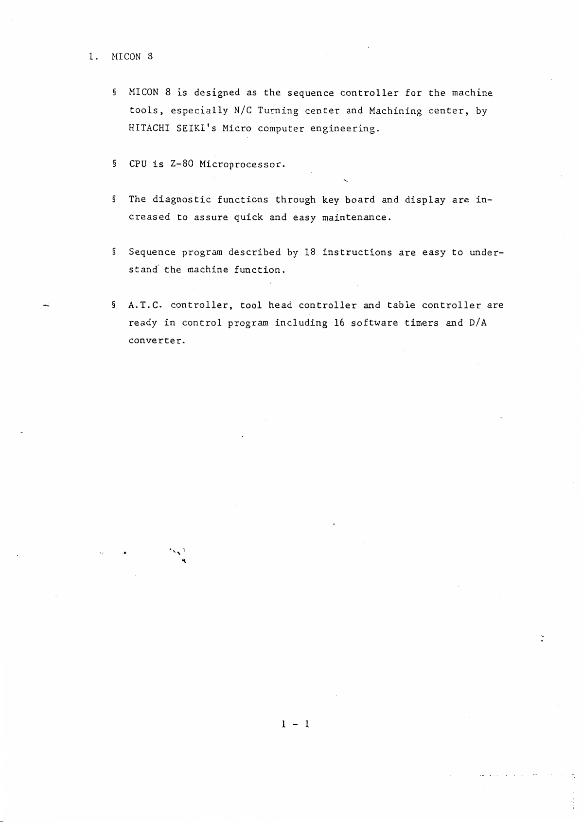
1.
MI
§
CON
MICON
8
8
is
designed
as
the
sequence
controller
for
the
machine
tools,
HITACHI
§
CPU
§
The
creased
§
Sequence
stand
§
A.T.C.
ready
converter.
especially
SEIKI's
Z-80
is
diagnostic
to
program
the
machine
controller,
control
in
N/C
Micro
Microprocessor.
functions
assure
quick
described
function.
tool
program
Turning
computer
through
and
head
including
center
easy
18
by
controller
and
engineering.
board
key
maintenance.
instructions
16
software
Machining
and
and
table
display
are
timers
center,
are
easy
to
controller
and
by
in¬
under¬
are
D/A
*
1
1
-

2.
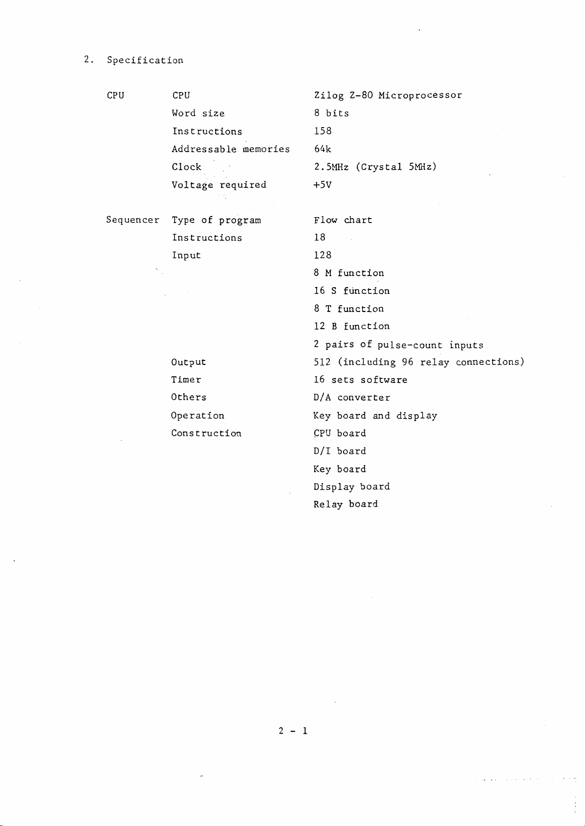
Specification
CPU
Sequencer
CPU
Word
size
Instructions
Addressable
Clock
Voltage
Type
Instructions
Input
Output
of
memories
required
program
Zilog
8
bits
158
64k
2.5MHz
+5V
Flow
18
128
8
M
function
16
S
8
T
function
B
12
2
pairs
512
(including
Z-80
(Crystal
chart
function
function
of
Microprocessor
5MHz)
pulse-count
96
relay
inputs
connections)
Timer
Others
Operation
Construction
16
sets
converter
D/A
board
Key
board
CPU
board
D/I
board
Key
Display
Relay
software
board
board
and
display
2-1


3.
Construction
+5V
+5V
+12V
Battery
Bus
(Optional)
nn
ULJ
Display
Key
board
PCI
CN8
CN14
CN10
KB3
KB
PC2
CPU
Board
PT.CODA
CN13
2
-
CN3
Output
Board
0*
CN2
PC3
CN1
Relay
CN12
CN11
dl
{II
U
j-|
!
!
y
Analog
10V
+/-
port
_D/0
(Optional)
ID
Id
ID-
ID
output
_
Spindle
drive
Ex.
Printer
Output
Machine
N/C
unit
Id
r
CN9
+5V
PC4
N/C
CN7
Input
PT.IN
CN6
Input
Board
0*
-
CN5
Machine
N/C
CN4
___
!
t
:
i
it
UV
----
L
n
7.
%
in
jj
b*
MICON
8
CONSTRUCTION
3-1


4.
Software
A
program
CON
MI
of
8.
The
Z-80
The
interpreted
HITACHI
by
machine
and
is
sequence
programming
Microprocessor.
programming
to
assembler
SEIKI
controlled
program,
language
language
make
to
Control
program
Max.
by
by
part
machine
Software
8
k
(two)
2
which
the
of
the
of
of
control
(memory)
programs,
stored
are
control
sequence
control
program
Sequence
program
Max.
8
in
program
program,
program,
k
named
the
easy.
Control
memory
the
is
which
is
developed
of
assembler
is
4.1
4.
Control
1.
2.
3.
4.
5.
6.
1.
1
Program
Control
Interpreter
Timer
Key
A,
D/A
Machifte
control
board
B
phase
converter
Interpreter
Sequence
interpreted
machine
program
(Sequence
and
control
function
to
function
consists
display
control
(A.T.C.,
program
the
correctly.
of
program
control
Table
described
assembler,
following
assembler)
to
etc.)
by
that
so
programs.
18
instructions
MICON
be
will
8
will
perform
4-1
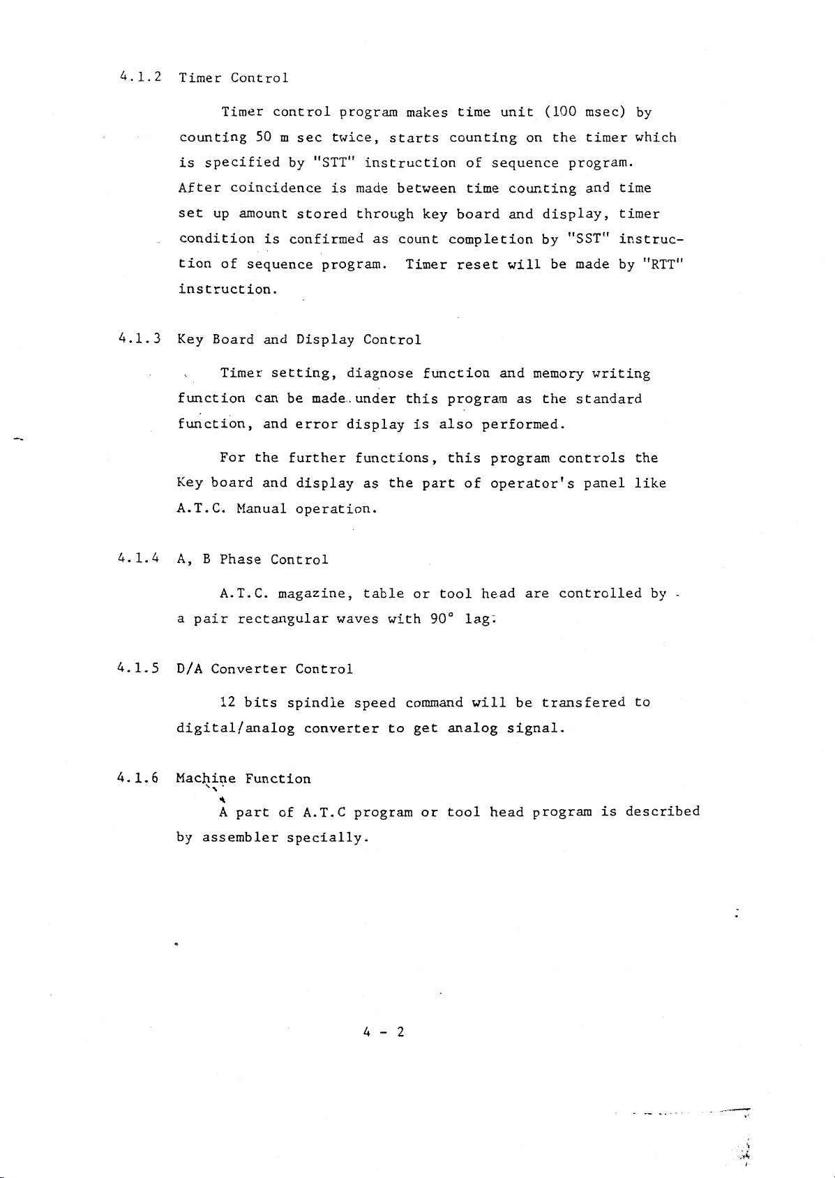
4.1.2
Timer
Control
Timer
control
program
makes
time
unit
(100
msec)
by
4.1.3
counting
is
specified
After
set
up
condition
tion
of
instruction.
Key
Board
Timer
function
function,
For
Key
board
A.T.C.
50
m
by
coincidence
amount
confirmed
is
sequence
and
setting,
can
be
and
the
further
and
Manual
twice,
sec
"STT"
is
stored
program.
Display
made.
error
display
operation.
starts
instruction
made
through
as
Control
diagnose
under
display
functions,
the
as
between
key
count
Timer
function
this
is
part
counting
of
time
board
completion
reset
program
also
performed.
this
of
on
sequence
counting
display,
and
by
will
and
memory
the
as
program
operator's
the
program.
"SST"
made
be
standard
controls
timer
and
writing
panel
which
time
timer
instruc-
"RTT"
by
the
like
4.1.4
4.1.5
4.1.6
B
Phase
A,
A.T.C.
a
pair
D/A
rectangular
Converter
12
bits
digital/analog
Machine
by
Function
A
part
assembler
Control
magazine,
Control
spindle
converter
A.T.C
of
specially.
table
waves
speed
program
or
with
command
to
get
or
tool
90°
lag".
will
analog
tool
head
head
are
be
signal.
program
controlled
transfered
is
by
-
to
described
4-2

4.2
4.2.
Sequence
1
List
Program
of
Instructions
Instructions
No.
1
2
3
4
5
6
Instructions
BRU
CALL
CLA
GOTO
JMP
MCP
To
jump
the
in
call
To
sequence
To
clear
output
To
jump
specified
To
jump
the
in
To
compare
with
so
upon
of
a
as
confirming
the
(yes)
code
ous
Description
to
the
sequence
the
subroutine
program
the
indication
signal
to
the
the
in
the
to
control
the
miscellaneous
to
present
with
skip
to
that
signal.
address
program
fixed
control
address
program
present
the
that
command
the
of
specified
of
of
address
program
specified
command
code
next
the
content
is
miscellene-
Remarks
the
each
signal
command
identical
8
9
10
11
7
MCPN
NOP
RETN
RTO
RTT
To
compare
a
miscellaneous
to
skip
confirming
present
(no)
with
code
No
This
tion
return
main
To
each
To
signal.
operation
command
with
routine.
reset
output
reset
the
the
to
that
command
that
the
from
the
each
present
code
next
the
is
of
(no
program
applied
is
CALL
the
subroutine
ON/OFF
signal
timer
command
signal
command
content
identical
not
the
miscellaneous
command
indication
so
upon
of
execution)
combina¬
in
so
to
as
the
with
as
the
to
of
4-3

No.
Instructions
Description
Remarks
12
13
14
15
16
17
SNI
SNIN
SNO
SNON
SST
STO
skip
To
firming
present
with
To
skip
firming
present
(no)
To
skip
firming
present
that
To
skip
firmation
present
(no)
To
skip
firming
timer
'
To
each
that
with
of
with
has
.set
output
the
next
that
command
the
that
of
the
the
next
the
command
that
the
next
that
the
command
the
output
the
next
that
command
that
the
next
that
the
elapsed
the
ON/OFF
signal
command
content
is
input
command
content
is
not
the
of
command
content
is
identical
command
the
is
not
the
of
command
time
(yes)
identical
signal.
identical
input
signal.
content
identical
output
set
.
indication
upon
of
upon
of
upon
of
upon
of
upon
on
con¬
the
(yes)
con¬
the
signal.
con¬
the
with
con¬
the
signal.
con¬
a
of
18
STT
*N\
To
'•
set
each
timer
*
4-4
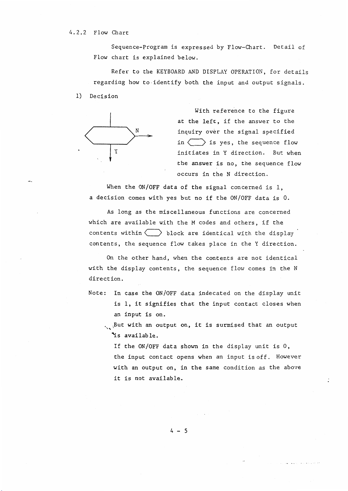
4.2.2
Flow
Chart
1)
Flow
regarding
Decision
When
a
decision
As
Sequence-Program
chart
Refer
Y
long
is
to
how
the
comes
explained
the
to-
identify
N
ON/OFF
with
the
as
KEYBOARD
is
expressed
below.
AND
both
at
the
inquiry
in
<(
initiates
the
occurs
data
yes
of
but
miscellaneous
DISPLAY
the
With
left,
answer
in
the
no
by
input
reference
over
is
yes,
in
is
the
signal
the
if
functions
Flow-Chart.
OPERATION,
and
the
if
the
signal
the
direction.
Y
the
no,
N
direction.
concerned
ON/OFF
are
output
the
to
answer
specified
sequence
sequence
is
data
concerned
Detail
for
signals.
figure
to
But
1,
is
of
details
the
flow
when
flow
0.
which
contents
contents,
with
direction
Note
:
On
the
are
In
is
an
But
'is
If
the
with
it
available
within
the
the
other
display
.
case
1,
input
with
available.
the
input
an
is
\
sequence
hand,
contents,
the
it
signifies
is
an
ON/OFF
contact
output
available.
not
with
y
the
block
flow
when
ON/OFF
on.
output
data
opens
on,
M
are
takes
the
the
data
that
on,
shown
the
in
codes
identical
place
contents
sequence
indecated
the
is
it
in
when
same
and
input
surmised
the
an
condition
others,
with
in
are
flow
on
contact
display
input
the
the
the
Y
not
comes
that
unit
off.
is
the
if
display
direction.
identical
in
display
closes
an
is
the
as
the
unit
when
output
0,
However
above
N
4-5
Decision
Y
N
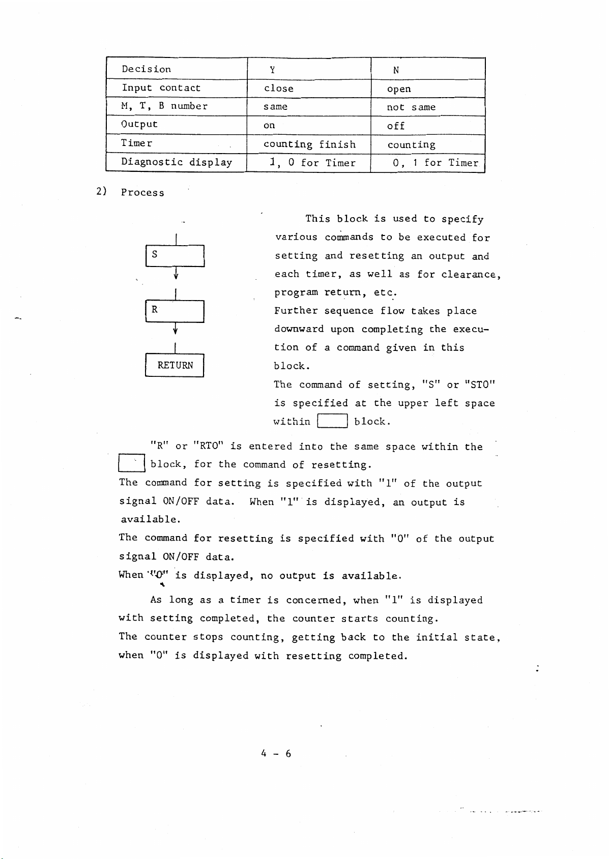
2)
Input
T,
B
M,
Output
Timer
Diagnostic
Process
S
R
RETURN
contact
number
T
T
display
close
same
on
counting
1
0
,
various
setting
each
program
Further
downward
tion
block.
finish
for
This
timer,
of
Timer
block
commands
and
resetting
as
return,
sequence
upon
a
completing
command
is
well
etc.
open
not
off
counting
0,
used
be
to
as
flow
given
same
for
1
to
executed
an
output
for
takes
the
in
Timer
specify
for
and
clearance,
place
execu¬
this
"R"
block,
The
command
signal
available.
The
command
signal
When
'I'-O”
As
with
The
when
setting
counter
"0"
"RTO"
or
for
for
ON/OFF
for
ON/OFF
is
displayed,
as
long
completed,
stops
is
displayed
the
setting
data.
resetting
data.
a
is
entered
command
When
no
timer
counting,
with
The
is
within
is
specified
"1"
is
output
is
concerned,
the
resetting
command
specified
into
of
resetting.
is
specified
is
counter
getting
of
at
block.
the
same
with
displayed,
with
available.
when
starts
back
completed.
setting,
the
space
"1"
an
"0"
"1”
counting.
the
to
upper
of
output
is
"S"
left
within
the
the
of
displayed
initial
or
output
is
output
"STO"
space
the
state,
4-6

With
the
indication
clear
command
executed,
no
output
is
3)
available.
tion,
the
the
main
Process
Output
Timer
Diagnostic
Subroutine
CALL
T
JMP
T
When
subroutine
program.
display
the
program
comes
S
on
count
1
routine
The
for
When
a
to
return
to
start
symbol
or
shift
effect
the
This
the
command
end
symbol
which
is
a
jump
subroutine
made
is
the
with
off
reset
stands
is
defined
used
the
to
to
program
is
shift
a
R
0
make
to
subroutine.
is
the
input
made
for
separately.
a
completed,
main
flow
program
further
to
a
call
execu¬
to
sub¬
4)
Non
operation
NOP
T
the
in
down
direction.
4
7
-
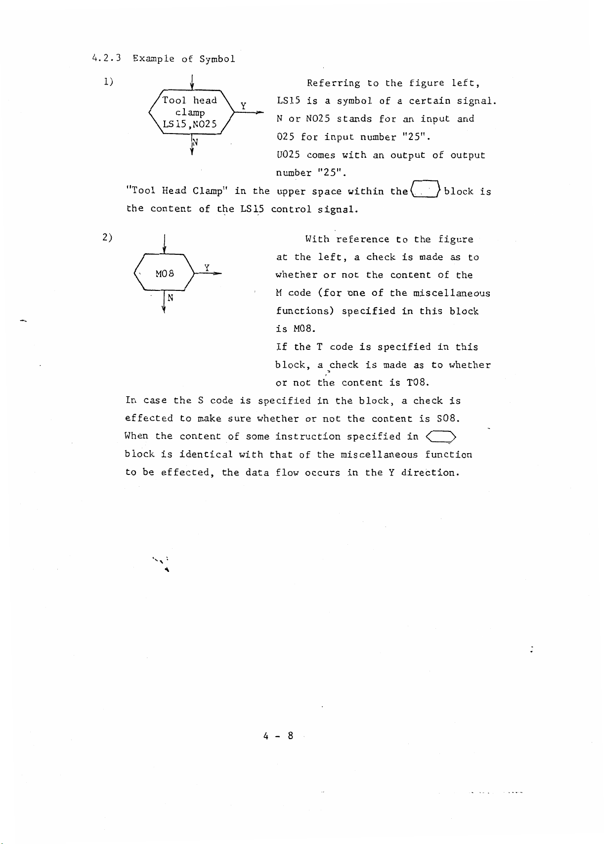
4.2.3
Example
of
Symbol
2)
i)
i
Tool
LS15.N025
head
clamp
N
Y
LS15
N
025
U025
number
"Tool
the
Head
content
i
8
MO
f
Clamp"
the
of
Y
in
LS15
the
upper
control
at
whether
M
functions)
is
If
block,
or
for
the
code
M08.
the
Referring
a
is
N025
input
comes
"25".
space
signal.
left,
or
(for
T
a
reference
code
check
With
symbol
stands
to
number
within
a
one
is
an
check
the
of
is
with
not
specified
the
certain
of
a
an
for
"25".
output
(
the
to
is
content
the
in
specified
made
of
)
figure
of
left,
signal.
and
output
block
as
the
figure
input
the
made
miscellaneous
this
block
in
this
to
whether
as
is
to
In
case
effected
When
block
be
to
the
is
effected,
S!
*
the
S
to
make
content
identical
code
the
is
sure
of
with
specified
whether
some
data
or
not
instruction
that
of
flow
the
in
not
or
the
occurs
content
the
block,
the
content
specified
miscellaneous
the
in
T08.
is
a
in
direction.
Y
check
is
<(
function
is
S08.
)>
4-8
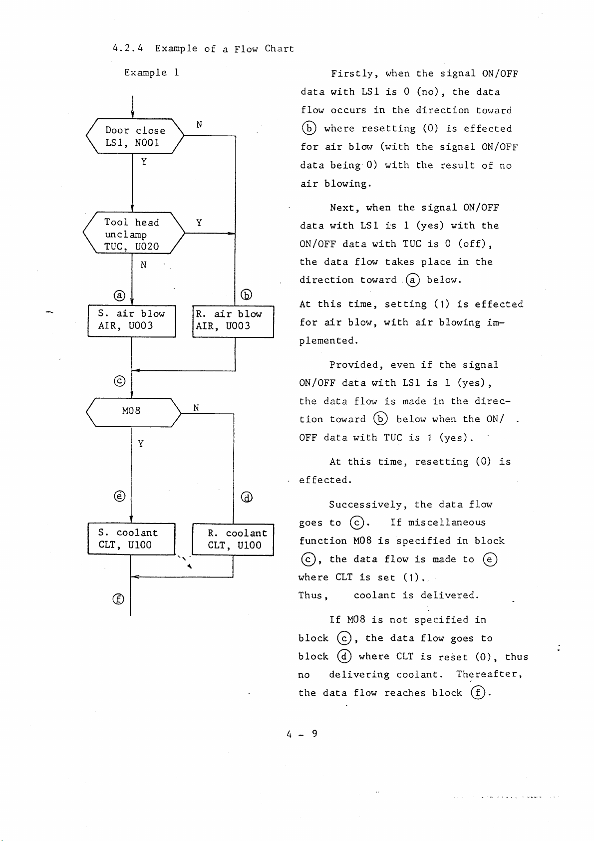
4.2.4
Example
of
a
Flow
Chart
Door
LSI,
Tool
unclamp
TUC,
©
S.
air
AIR,
Example
’
close
N001
Y
head
U02Q
N
blow
U003
1
N
Y
ON/OFF
data
flow
©
for
data
air
data
the
Firstly,
with
occurs
where
blow
air
being
blowing.
Next,
with
data
data
flow
direction
R.
AIR,
air
©
blow
U003
this
At
air
for
plemented.
time,
blow,
when
LSI
is
in
resetting
(with
0)
with
when
LSI
is
with
takes
toward
setting
with
the
the
the
(no),
0
direction
the
the
1
(yes)
TUC
place
(a)
air
signal
(0)
signal
result
signal
is
below.
(1)
blowing
the
is
effected
ON/OFF
with
0
(off),
in
is
ON/OFF
data
toward
ON/OFF
of
no
the
the
effected
im¬
S.
CLT,
©
©
8
MO
©
coolant
U100
the
if
1
is
in
when
(yes)
1
resetting
data
the
made
is
delivered.
specified
flow
is
reset
signal
(yes)
the
direc¬
the
.
(0)
flow
block
in
to
in
goes
to
(0),
Thereafter,
,
ON/
is
©
thus
.
is
the
with
(b)
time,
is
set
even
LSI
made
is
below
is
TUC
miscellaneous
If
specified
flow
(1).
is
not
data
CLT
coolant.
Provided,
ON/OFF
N
Y
the
tion
OFF
effected.
©
goes
R.
CLT,
coolant
U100
function
©)
where
Thus
block
block
no
data
data
data
flow
toward
with
this
At
Successively,
to
(©
M08
the
,
,
data
CLT
is
coolant
M08
If
,
©
where
©
delivering
4-9
the
data
flow
reaches
block
(f)
.

Example
2
Call
I
TIDX
Subroutineÿ
TIDX
c
T
is
given
(mostly,
near
When
made
is
J
If
the
this
there
below,
the
end
subroutine
the
to
a
is
it
symbol
of
the
main
flow
signifies
subroutine
of
flow
is
program.
chart
symbol
"TIDX"
chart)
executed,
such
subroutine
is
as
given
.
shift
a
*
Return
4-10

5.
Hardware
5.1
Input
Input
Signal
signal
Described
Signal
signal
Described
Signal
Signal
M,
B
function
Note
T
:
1
from
2
from
—
function
4
digits
Nxxx
by
outside
Mxx,
Txx
by
N/C
B.C.D.
—
(Binary
1,2,4,8,10,20,40,80
—
1,2,4,8,10,20,40,80,100,200,400,800
T
function
—
N001-N128
Limit
Push
Relay
N/C
and
Bxxx
function
M
T
function
B
function
Coded
on
switch
button
contact
etc.
Decimal)
lathe
the
or
.
—
N256
2
2
3
digits
digits
digits
8
inputs
—
16
inputs
Input
Input
Output
signal
Described
Signal
Signal
signal
Described
Signalÿ
Signal
signal
Described
§U001
§U09
7
Last
unit,
3
from
—
4
from
--
—
—
2
by
N/C
12
by
ATC,
2
rectangular
by
U096
U512
digits
only
Rxx
bits
Phase
Uxxx
first
binary
A,
Table
Signal
Dummy
are
B
used
2
and
waves
to
signal
digits
R01
2
pairs
Tool
outside
for
—
with
the
are
R12
PA1,
head.
effective
90
tool
Spindle
PB1
deg.
Solenoid
Lamp
Relay
N/C
offset
PA2,
lag.
etc.
on
speed
coil
inside
the
PB2
N/C
MIC0N
8.
5-1
Timer
Described
Setting
time
by
TRxx
There
0.1
are
25
16
timers
0
5
.
sec.
.
or
1
25.5
min.
Analog
output
±10V
Digital
for
spindle
(12
bits
speed
binary)
command
to
analog
converter
*
5-2

5.2
CPU
Board
CN14
H
CN8
PI
o
2
u
CPU
ic
I
i
I
1
I
LJ
z
I
u
I
CH2
O
O
i
rn
CJ
T
CN
z
o
D/A
converter
I
2
CJ
VR1
VR2
CN11
OO
}
=3
s
o
<
Q
>
Q
z
o
z
2
O
converter
O
O
O
O
w
DC
C\
on
O
X
sOH
Og
2QJ
w
/DC
CN12
PI
P2
P3
P4
P5
P6
7
P
°U§
Oxl
a
w
-I
Oo
O
o+g
Oxl
o
CO
u
z
PL,
cu
P1,P2
o
P3
CH2
WRSW
CMSW
PCI
LED1
LED2
LED
LED4
i
P7
-
P-ROM
and
Control
-
P6
Sequence
GND
-
Bridge
Switch
Switch
PC3
-
Power
Battery
ON/
Interrupt
ON/
3
Halt
ON/
Power
ON/
socket
P7
(System)
program
to
on
on
source
condition
inhibit
to
write
be
to
connector
low
source
program
interruption
RAM
level
disable
+5V
parameter
sequencer
«$C
5V
12V
GND
BY1
LGND
+15V
-15V
5N
N
DAOUT(N)
VRl
VR2
(GND)
(GND)
(GND)
(LGNft)
(N)
(N)
(N)
)
CLOCK
+5V
+12V
OV
Battery
OV
+15V
-15V
+5V
OV
Analog
Analog
(
adjustment
2.5MHz
output
output
—
5-3
]—
—
Battery
D/A
converter

5.3
Architecture
5.3.1
General
CPU
2.5MHz
r
I
3TJ
I
CLOCK
6
~
i
i
r
i
I
n
5MHz
i
1
T
Memory
n
.
y
-7-TC-2k~fiQM-
(ÿ6Tc2kR0Mr~iÿfeROM)
4
fcx-ik
*
2
i
RAM
&£
Output
(D/A
I
converter)
1
F
3
XI
CO
a
C3
Q
-T3
<
CO
CO
2
I
Key
fl
&
display
Input
£
*
S\
H
5-4

5.
3.2
Memory
r-
PQ
Q
o
pa
a
-
AB10
Control
Control
AO
A15
MDBO
-
-
MDB7
ABO
AB15
0
f
7
AB11
AB12
AB13
AB14.15
(enable)
2
k
3/8
Decoder
ROM
OOOO
07FF
0800
ABO
0
3
7
OFFF
1000
i
17FF
Sequence
1800
Sequence
1FFF
i--
Q
o
a
2000
2
7FF
Sequence
2800
Sequence
2FFF
4000
o
ja
nS
3
Q
2k
47FF
(4FFF)
ROM
or
4k
ROM
Control
3
i
PQ
<
5-5

Memory
MDBO
3
-
MDBO
MDB3
MDB4
MDB
ABO
lk
RAM
4
0
r
-
<
3
(0
bits
lk
RAM
4
bits
0
-
ABO
>
9
J
0
'i
AB9
15
-
3000
I
33FF
-
7
I
U
ABO
9
J
AB9
-
MDBO
MDB
-
3
f
-
C3
Three
0
I
I
I
RAMs
o
o
Timer
Output,
are
table
lk
4
backed
RAM
bits
timer
etc.
up
dummy
the
by
etc.
battery.
0
3400
I
ABO
9
J
AB9
-
37FF
'
5-6
 Loading...