

Page 1

SEIKI - SEICOS
å10M/16M/18M
INSTRUCTION MANUAL
5 OPERATION
Edition 1.02 NO-0000-1-0221-E-1-02
Hitachi Seiki Deutschland
Werkzeugmaschinen GmbH
Page 2

2
Page 3

CONTENTS
1. OUTLINE .......................................................................................... 1 -1
2. SPECIFICATIONS ............................................................................... 2 - 1
3. OPERATION......................................................................................... 3 -2
I. Basic Machine Operation ................................................................... 3 -2
1. Manual Operation.................................................................................................................3 -3
1-1 Jog Feed ....................................................................................................................... 3 -3
1-2 Manual Reference Point Return.................................................................................... 3 -4
1-3 Rapid T raverse .............................................................................................................3 -5
1-4 Manual Handle Feed ..................................................................................................... 3 -5
1-5 Manual Handle Interrupt (Optional)................................................................................3 -6
2. Automatic Operation ............................................................................................................ 3 -7
2-1 Automatic Operation ..................................................................................................... 3 -7
2-2 Selecting the Run Program .......................................................................................... 3 -8
2-3 Stopping the Automatic Operation................................................................................. 3 -8
2-4 Dry Run ........................................................................................................................ 3 -9
2-5 Single Block .................................................................................................................. 3 -9
2-6 Override ...................................................................................................................... 3 -10
2-7 Pre-Program Machining T ime display Function (Optional) ......................................... 3 -10
2-8 Tape Operation (Simple DNC Operation) ................................................................... 3 -11
2-9 DNC Operation (Optional) .......................................................................................... 3 -11
2.10 Submemory .............................................................................................................. 3 -15
3. Operation Related to Safety............................................................................................... 3 -20
3-1 Emergency Stop ......................................................................................................... 3 -20
3-2 Overtravel ................................................................................................................... 3 -20
4. NC Operation Keys............................................................................................................3 -21
5. Operation Related to W Setter .......................................................................................... 3 -23
5-1 Outline ........................................................................................................................ 3 -23
5-2 Input Signals and V arious Operations......................................................................... 3 -23
5-3 Setting the Work Setter Datum Level ......................................................................... 3 -24
5-4 Setting the Work Setter Master Hole........................................................................... 3 -25
5-5 Setting the Work Setter Coordinate Modification ........................................................ 3 -26
5-6 Rewriting the Work Zero Point Offset Amount Manually ............................................. 3 -27
5-7 Setting the Tool Setter................................................................................................. 3 -28
5-8 Parameters................................................................................................................. 3 -31
5-9 Others......................................................................................................................... 3 -32
5-10 5-Face Working Machine’s W Setter ........................................................................ 3 -33
5-1 1 Appendix.................................................................................................................... 3 -34
i
Page 4

II. Screen Operation ............................................................................. 3 -38
1. Screen Layout and Basic Operation..................................................................................3 -39
1-1 Main Display Area ....................................................................................................... 3 -40
1-2 Alarm Display Area...................................................................................................... 3 -40
1-3 Program Number Display Area................................................................................... 3 -41
1-4 Key Input Area............................................................................................................. 3 -41
1-5 Error Message ............................................................................................................ 3 -41
1-6 Function Menu ............................................................................................................ 3 -41
1-7 Tree Chart................................................................................................................... 3 -42
2. Operation of Overall Screen ..............................................................................................3 -44
2-1 Program...................................................................................................................... 3 -45
2-2 Tool Path Plot.............................................................................................................. 3 -45
2-3 Tool Data..................................................................................................................... 3 -45
2-4 S, S % and F, F %.......................................................................................................3 -45
2-5 Dwell........................................................................................................................... 3 -45
2-6 Load Meter .................................................................................................................. 3 -46
2-7 Position Data .............................................................................................................. 3 -46
2-8 G code and M code..................................................................................................... 3 -46
2-9 T ime Measurement..................................................................................................... 3 -46
2-10 Date and Time .......................................................................................................... 3 -48
3. Position..............................................................................................................................3 -49
3-1 Rewriting the Relative Coordinate System ................................................................. 3 -50
3-2 Setup Work................................................................................................................. 3 -50
3-3 Command Value Display ............................................................................................ 3 -50
3-4 Restart (Option) .......................................................................................................... 3 -50
3-5 Floating Reference ..................................................................................................... 3 -50
4. Work Coordinate (Offset) ..................................................................................................3 -53
4-1 Data Display and Setting ............................................................................................ 3 -54
4-2 Function Menu ............................................................................................................ 3 -55
4-3 Work Setter................................................................................................................. 3 -55
4-4 Number Search .......................................................................................................... 3 -55
4-5 Work Coordinates Setting Function............................................................................ 3 -55
4-6 Setting the External Work Zero Point Offset ............................................................... 3 -56
5. Set (Data) ..........................................................................................................................3 -57
5-1 Display and Setting ..................................................................................................... 3 -57
5-2 Number Search .......................................................................................................... 3 -57
5-3 Automatic Override ..................................................................................................... 3 -62
5-4 Eco¥eco ..................................................................................................................... 3 -64
6. Macro V ariable ................................................................................................................... 3 -65
6-1 Macro V ariable and Dat a Display ................................................................................ 3 -65
6-2 Number Search .......................................................................................................... 3 -65
7.Plot ...................................................................................................................................... 3 -67
8. Plotting Parameters........................................................................................................... 3 -69
ii
Page 5

9. Tool (Offset).......................................................................................................................3 -72
9-1 Compensation V alue Setting....................................................................................... 3 -73
9-2 Name Setting .............................................................................................................. 3 -73
9-3 Data Delete................................................................................................................. 3 -73
9-4 Sensor setting............................................................................................................. 3 -74
9-5 Reference Gauge ....................................................................................................... 3 -74
9-6 Tool Change................................................................................................................ 3 -74
9-7 Tool Setter................................................................................................................... 3 -74
9-8 Number Search .......................................................................................................... 3 -74
9-9 Safety Guard............................................................................................................... 3 -74
10. Alarm/Diagnosis............................................................................................................... 3 -76
10-1 Alarm History............................................................................................................. 3 -77
11. System.............................................................................................................................3 -78
11-1 Parameter Setting ..................................................................................................... 3 -78
11-2 Diagnosis.................................................................................................................. 3 -80
11-3 Mechanical Compensation........................................................................................ 3 -82
11-4 Position Region ......................................................................................................... 3 -83
11-5 Software Version....................................................................................................... 3 -84
11-6 Date and Time........................................................................................................... 3 -85
11-7 SLBUS ...................................................................................................................... 3 -86
11-8 System Table ............................................................................................................ 3 -87
1 1-9 F Menu ...................................................................................................................... 3 -87
12. Program........................................................................................................................... 3 -92
12-1 Operating Key Input Area On Screen........................................................................ 3 -93
12-2 Displaying Program .................................................................................................. 3 -93
12-3 Creating New Program ............................................................................................. 3 -93
12-4 Deleting Program...................................................................................................... 3 -93
12-5 Initialization Of Program Memory.............................................................................. 3 -94
12-6 Program Search ....................................................................................................... 3 -94
12-7 Program Copy .......................................................................................................... 3 -94
12-8 Changing Program Number...................................................................................... 3 -94
12-9 Program Editing (Edit Mode or Background Editing)................................................. 3 -95
12-10 Word Search .......................................................................................................... 3 -95
12-11 Background Edit (Program Screen Only) ............................................................... 3 -97
12-12 Range Assignment Edit Operation (Program Screen Only) ................................... 3 -99
12-13 Word Convert (Program Screen Only) ................................................................. 3 -100
12-14 Macro Variables .................................................................................................... 3 -102
13. Program List .................................................................................................................. 3 -103
13-1 Program List ........................................................................................................... 3 -103
13-2 Program Search ..................................................................................................... 3 -105
13-3 Program Delete ...................................................................................................... 3 -105
13-4 Program Arrangement ............................................................................................ 3 -106
13-5 Program Merging .................................................................................................... 3 -106
13-6 Initialization Of Program Memory............................................................................ 3 -106
iii
Page 6

14. Input / Output .................................................................................................................3 -107
14-1 Program List ........................................................................................................... 3 -108
14-2 Data Setting Table ................................................................................................... 3 -108
14-3 Check .....................................................................................................................3 -110
14-4 Details Of Setting Data ........................................................................................... 3 -110
14-5 Call Select (Option)................................................................................................. 3 -113
14-6 Don-Don FD I/O Screen ......................................................................................... 3 -113
15. Input / Output (With PC Card Used) .............................................................................. 3 -115
15-1 Available PC Cards................................................................................................. 3 -1 15
15-2 Initial Formatting of PC Card................................................................................... 3 -1 1 5
15-3 Starting PC Card Operation .................................................................................... 3 -11 5
15-4 Ending PC Card Operation ..................................................................................... 3 -117
15-5 PC Card Input/Output ............................................................................................. 3 -118
15-6 Operating the PC Card Directory............................................................................ 3 -120
15-7 Error Messages ...................................................................................................... 3 -125
4. INDIVIDUAL PROGRAMS ................................................................... 4 -4
I. Tool Life Management........................................................................ 4 -4
1. Tool Life Management..........................................................................................................4 -4
2. S pare Tool Management ...................................................................................................... 4 -6
3. Premachining Tool check.....................................................................................................4 -7
4. Tool Skip And Tool Reset (Option) ....................................................................................... 4 -7
5. Tool Life Management Program...........................................................................................4 -7
6. Tool Life Management Operation ....................................................................................... 4 -11
7. Tool Life Screen .................................................................................................................4 -12
8. Spare Tool Screen .............................................................................................................4 -16
9. Tool Status List Screen...................................................................................................... 4 -19
10. Tool Life Management Parameters And Their Setting ...................................................... 4 -21
11. Alarms..............................................................................................................................4 -21
II. Cutting Monitoring Unit ................................................................... 4 - 22
1. Outline ...............................................................................................................................4 -22
2. Monitoring Method..............................................................................................................4 -22
3. Monitoring Functions..........................................................................................................4 -23
4. Cutting Monitoring Program ...............................................................................................4 -26
5. Data Setting....................................................................................................................... 4 -29
6. Cutting Monitoring Operation .............................................................................................4 -31
7. Set Load Screen................................................................................................................4 -34
8. Load Graph Screen ........................................................................................................... 4 -37
9. Life Graph Screen.............................................................................................................. 4 -38
10. Display And Setting Of Parameters.................................................................................4 -39
11. Alarms..............................................................................................................................4 -43
iv
Page 7

III. Tool Peculiar Number Function .................................................... 4 -44
1. Function.............................................................................................................................4 -44
2. Tool Peculiar Number Method (Parameter 8004 #7 = 0)....................................................4 -44
3. Number Method By Functions (Parameter No. 8004 #7 = 1).............................................4 -47
IV. Staf ........................................................................................ 4 -50
1. Periodic Check ..................................................................................................................4 -50
2. Status Display/OK Monitor................................................................................................. 4 -52
3. Instruction Manual Information ........................................................................................... 4 -53
4. LSSOL Diagram (Switch Status) ....................................................................................... 4 -54
V. SHG ........................................................................................ 4 -56
1. Outline ............................................................................................................................... 4 -56
2. SHG Cutting Mode ............................................................................................................. 4 -56
VI. Thermal Displacement Offset Function....................................... 4 -59
1. Thermal Displacement Offset Function (Main)..................................................................4 -62
2. Thermal Displacement Offset Function (Maintenance) .....................................................4 -64
3. Thermal Displacement Offset Function (Maintenance 2) ..................................................4 -64
VII. UUP Function.................................................................................. 4 - 6 5
1. General Description........................................................................................................... 4 -65
2. Connection Of UUP ........................................................................................................... 4 -65
v
Page 8

vi
Page 9

1. OUTLINE
The SEIKI-SEICOS Σ 10M/16M/18M has realized a miniaturized high-reliability system by
integrating up-to-date device technology. TheΣ10M/16M can perform high-speed, highaccuracy machining, using 64-bit RISC (Reduced Instruction Set Computer).
The operation system as a human interface is designed very user-friendly from a perspective of
the user. For example, a canned cycle editing function is provided as an option in order to
facilitate editing of canned cycles.
This manual describes how to operate the following models.
See “SEIKI-SEICOS Σ10M/16M/18M-PROGRAMMING” for programming, and “SEIKI-SEICOS
Σ10/16/18/21” for alarms and maintenance.
Model Designation
SEIKI-SEICOS Σ10M S-Σ 10M
SEIKI-SEICOS Σ16M S-Σ 16M
SEIKI-SEICOS Σ18M S-Σ 18M
1-1 Precautions for Reading This Manual
(1) This manual and SEIKI-SEICOS SΣ10M/16M/18M-PROGRAMMING describe the entire
functions of this NC unit, including the optional functions. The selected functions vary from
one machine to another. As some of the functions described in the manual are not
available, check the specifications of the machine beforehand.
(2) When there is any function not described “possible” in the manual, take it “impossible.”
(3) The information herein is subject to change without prior notice.
CAUTION
The programs, parameters, macro variables, and tool offset amounts have been stored in the
internal memory of the NC unit. Generally, they are not lost by turning on/off the power. They
may be erased by mistake or you are forced to erase the precious data saved in the memory in
order to recover from a failure.
Make back-up copies of various data in advance so that you can quickly recover from such an
unexpected incident.
CAUTION
Before starting machining, be sure to fully confirm proper operation of Machine by performing a
trial run.
Before using work coordinate data and tool offset data, be sure to confirm that the data have
been properly input.
1 - 1
Page 10

1 - 2
Page 11

2. SPECIFICATIONS
1. CONTROLLED AXES
1-1 Controlled Axes
The 3 axes, X, Y and Z, are controllable. Furthermore, up to 8 axes can be controlled by
adding the optional 5 axex; 4th through 8th axes.
1-2 Simultaneous Controllable Axes
The 3 axes, X, Y and Z, can be controlled simultaneously regardless of rapid traverse or cutting
feed. Furthermore, up to 8 axes can be controlled simultaneously (option). Table 1.2 shows
the configuration of the controlled axes.
Table 1-2
No. of Axes Axis Name Remarks
Standard 3 axes X, Y, Z
controlled axes
Additional axes 5 axes Select of of U, V, W, A,
control B and C
Simultaneous Standard 3 axes + All the axes specified by
controllable axes additional axes the system
(up to 8 axes)
(Note 1) The number of controlled axes, and relations between the axis names and axes can be
selected with prameters.
1-3 Increment System
There are two types of increment systems; IS-B and IS-C. You can select either of them by a
parameter. (Is-A is not available for the moment.)
Millimeter/inch switching is set with a parameter. For detailed description of parameter, refer to
“Parameters”.
1-4 Maximum Commandable Value
Table 1.4 shows the increment systems and commandable values.
1-5 10-Time Input
The input increment can be made 10 times larger by parameter setting. Table 1.5 shows the
commandable values.
2 - 1
Page 12
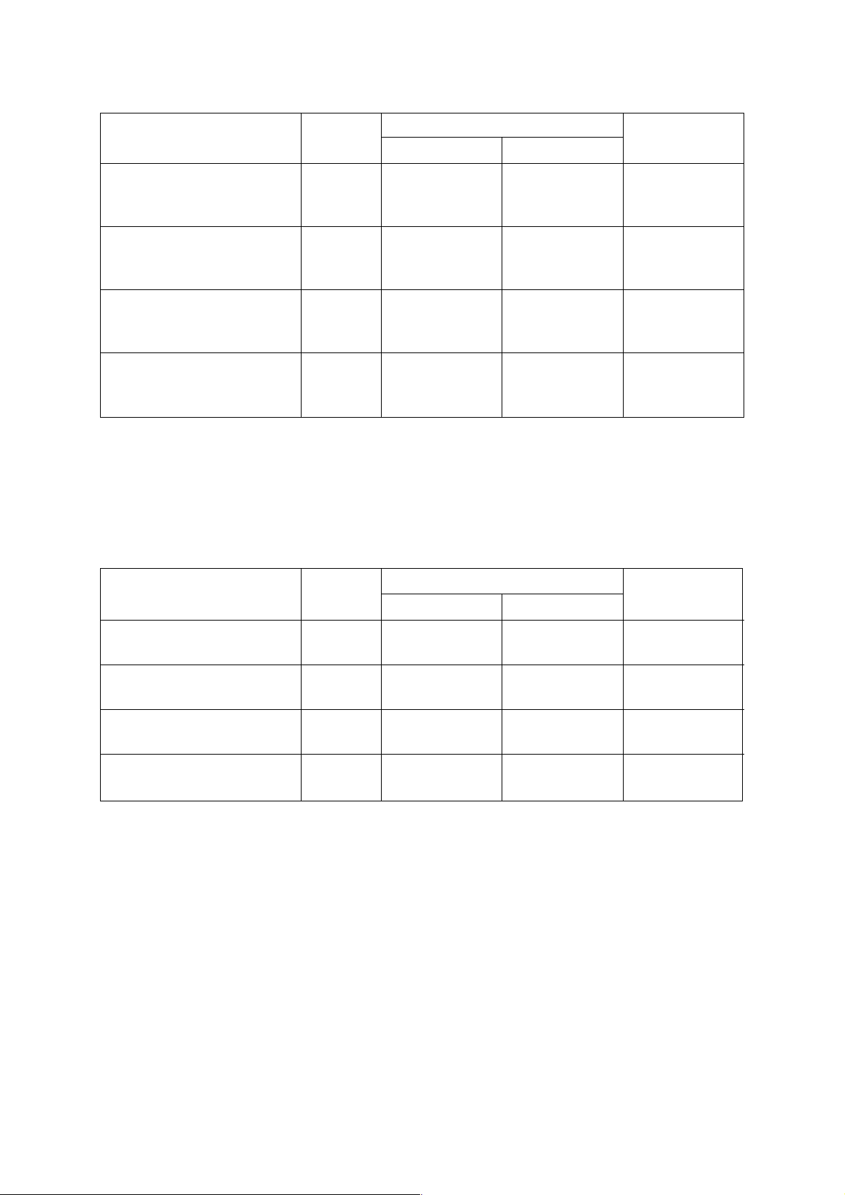
Table 1-4
Linear Axis
Unit Type
Input increment IS-A 0.01 0.001 0.01
IS-B 0.001 0.0001 0.001
IS-C 0.0001 0.00001 0.0001
Least command increment IS-A 0.01 0.001 0.01
IS-B 0.001 0.0001 0.001
IS-C 0.0001 0.00001 0.0001
Maximum stroke IS-A ±999999.99 ±99999.999 ±999999.99
IS-B ±99999.999 ±9999.9999 ±99999.999
IS-C ±9999.9999 ±999.99999 ±9999.9999
Maximum commandable IS-A ±999999.99 ±99999.999 ±999999.99
value IS-B ±99999.999 ±9999.9999 ±99999.999
IS-C ±9999.9999 ±999.99999 ±9999.9999
[10-Time Input Increment]
For the Types IS-B and IS-C, the input increment can be made 10 times larger by parameter
setting.
(mm) (inch)
Table 1-5
Rotary Axis
(deg.)
Linear Axis
Unit Type
Input increment IS-B 0.01 0.001 0.01
IS-C 0.001 0.0001 0.001
Least command increment IS-B 0.01 0.001 0.01
IS-C 0.0001 0.00001 0.0001
Maximum stroke IS-B ±99999.999 ±9999.9999 ±99999.999
IS-C ±9999.9999 ±999.99999 ±9999.9999
Maximum commandable IS-B ±999999.99 ±99999.999 ±999999.99
value IS-C ±99999.999 ±9999.9999 ±99999.999
(Note 1) For the Type IS-A, nothing is changed even if you set the parameter for 10-time input
increment.
(mm) (inch)
Rotary Axis
(deg.)
2 - 2
Page 13

1-6 Position Detector
The pulse encoder is provided as a standard position detector. Optionally, the pulse scale or
the Inductosyn detecting function can be selected. When the Inductosyn detecting function is
selected, however, you need a converter which serves as an interface equivalent to the pulse
scaler.
When adding an option for detecting an absolute position, an absolute encoder will be attached.
2 - 3
Page 14

2. INTERPOLATING FUNCTIONS
2-1 Positioning (G00)
Each axis can be fed at a rapid traverse rate independently by specifying G00.
2-2 Linear Interpolation (G01)
Linear interpolation is performed at the feed rate specified by an F-code in a G01 command.
2-3 Single Direction Positioning (G60)
Since this function allows precise positioning with backlash excluded, positioning can be
performed from only one direction.
2-4 Circular Interpolation (G02, G03)
Circular interpolation can be performed arbitrarily at 0 to 3600 at the feed rate specified by an
F-code in a G02 or G03 command.
2-5 Radius Designation on Arc (G02, G03)
R can be directly specified as a circular arc radius value, assuming I, J, and K to be a vector
amount from a start point to the center in circular interpolation.
2-6 Sine Curvilinear Interpolation <Virtual Axis Interpolation> (G07)
By performing interpolation without moving one axis within a circular arc plane (hypothetical
axis) in a helical cutting command, sine curvilinear interpolation is performed between the
remaining two axes.
2-7 Helical Cutting (G02,G03)
Another axis is linearly interpolated synchronously with circular interpolation.
2-8 Polar Coordinate Interpolation (G120,G121)
A command programmed in the orthogonal coordinate system is converted into a linear axis
move (tool) and rotary axis move (work rotation) to control a profile.
2-9 Cylindrical Interpolation (G271)
If a linear axis stroke and rotary axis angle are specified by a program command, the rotary
axis stroke internally specified in terms of angle is converted into a distance on the
circumference. As the distance on the circumference can be regarded a linear axis stroke on
the circumference, linear interpolation and cirfular interpolation can be performed in
combination with other linear axis.
2 - 4
Page 15

3. THREAD CUTTING
4. FEED FUNCTIONS
4-1 Rapid traverse Rate and Rapid Traverse Override
The speed in the axial direction is allowed up to 240,000 mm/min (IS-B).
An override can be applied to a rapid traverse rate by rapid traverse override.
4-2 Cutting Feed Rate and Feed Rate Override
A feed rate is allowed from 6 to 240,000 mm/min (IS-B).
Feed rate override allows you to apply an override in an increment of 10% from 0% to 200%.
Table 4-2 shows the feed rate command value range.
Table 4-2
Type F-command Range
Feed per
minute(G94)
Feed per
revolution (G95)
Threading (G33)
(Note 1) The type can be selected with a parameter.
(Note 2) The cutting feed rate is a command given relative to the reference axis.
(Note 3) The maximum cutting feed rate is limited by the cutting feed clamp rate set with a
parameter.
(Note 4) When an F1-digit feed option is added, F1-F9 have special meanings.
Metric input F60 F1~F999999 mm/min
F61 F0.1~3F999999.9 mm/minmin
F62 F0.01~F999999.99 mm/min/min
Inch input F51 F0.1~F99999.9 inch/minn
F52 F0.01~F99999.99 inch/min
Metric input F32 F0.01~F999.99 mm/rev
F33 F0.001~F999.999 mm/rev
Inch input F23 F0.001~F99.999 inch/rev
F24 F0.0001~F99.9999 inch/rev
Metric input F35 F0.00001~F999.99999 mm/rev
F26 F0.000001~F99.999999 mm/rev
Inch input F26 F0.000001~F99.999999 inch/rev
F17 F0.0000001~F9.9999999 inch/rev
2 - 5
Page 16

[Related Parameters]
No. 1003, #0 Sets the type IS-A, IS-B or IS-C.
#1
#2 = 0 Disables the input increment 10.
Enables the input increment 10.
No. 3401, #0 = 0 Specifies F23 for feed per revolution in inches.
1 Specifies F24 for feed per revolution in inches.
#1 = 0 Specifies F32 for feed per revolution in millimeters.
1 Specifies F33 for feed per revolution in millimeters.
#2 = 0 Specifies F51 for feed per minute in inches.
1 Specifies F52 for feed per minute in inches.
#3 = 0 Specifies F60 for feed per minute in millimeters.
1 Specifies F61 for feed per minute in millimeters.
#4 = 0 Specifies F26 for threading lead in inches.
1 Specifies F17 for threading lead in inches.
#5 = 0 Specifies F35 for threading lead in millimeters.
1 Specifies F26 for threading lead in millimeters.
#6 = 0 Feed per minute of 0mm abides by #3.
1 Feed per minute of 1mm for F62.
4-3 Override Cancel
A cutting feed override rate can be fixed at 100% by a signal from the machine.
4-4 Automatic Acceleration/Deceleration
Linear acceleration/deceleration is performed in case of rapid traverse, and exponential
function type acceleration/deceleration is performed in case of cutting feed or jog feed.
4-5 Dwell (G04)
Migration to operation in the next program block can be delayed by a specified time by a G04
command. Use P, X, or U for an address.
4-6 Exact Stop Check (G09)
In the block where G09 is specified, an imposition check is made at the end of block execution.
4-7 Exact Stop Check Mode (G61)/Cutting Mode (G64)
Normally, the G64 mode is effected and the program proceeds to the next block immediately
after interpolation is completed. If G61 is specified, the program will proceed to the next block
after entering imposition at the end point of each block, in the subsequent move commands.
The G61 mode is cancelled by specifying G64.
2 - 6
Page 17

4-8 Automatic Corner Override (G62)
An override is applied automatically to a cutting feed rate at a corner during tool diameter
compensation.
5. REFERENCE POINT
5-1 Reference Point Return A (G27 to G29)
Reference point return a includes the following:
(1) Manual reference point return
(2) Reference point return check (G27)
(3) Automatic reference point return (G28)
(4) Return from the reference point (G29)
5-2 Reference Point Return B (G30)
Second reference point return (G30) returns the axes to the position set in a parameter.
5-3 Third/Fourth Reference Point Return (G30)
The axes can be returned to the 3rd/4th reference point preset by a G30 command (P3, P4).
5-4 Floating Reference Point Return (G301)
The axes can be returned to the preset optional point of the machine.
6. COORDINATE SYSTEM
6-1 Coordinate System Setting (G92)
An axis command following G92 sets the coordinate system where a current tool coordinate
value will be a specified value.
6-2 Machine Coordinate System Selection (G53)
A tool moves to a position in the machine coordinate system by a G53 command.
6-3 Plane Designation (G17, G18, G19)
A G-code is used to specify the plane where you want to perform circular interpolation, tool
diameter compensation, and so on.
G17: X-Y plane, G18: Z-X plane, G19: Y-Z plane
6-4 Local Coordinate System Selection (G52)
With a G52 command, you can set a child coordinate system, that is, local coordinate system in
all the work coordinate systems (G54 to G59).
6-5 Work Coordinate System setting (G54 to G59)
One of the preset coordinate systems is selected by a G-code, G54 through G59. The
subsequent program is executed in that selected coordinate system. The number of additional
pairs is 60.
2 - 7
Page 18

7. COORDINATES AND DIMENSIONS
7-1 Absolute/Incremental Programming
Absolute/incremental programming is switched by a G-code.
G90 : Absolute programming
G91 : Incremental programming
7-2 Decimal Point Input
A decimal point can be input to the command data associated with a distance (angle), speed,
and dwell. A decimal point position is after the millimetric or inch units digit. Decimal point
usable addresses include X, Y, Z, A, B, C, U, V, W, I, J, K, R, P, and F. When P is a
subprogram number, however, the decimal point is not available.
7-3 Inch/Metric Conversion (G20, G21)
You can select the inch system/metric system as units of input by specifying G20/G21.
8. SPINDLE FUNCTIONS
8-1 Spindle Function (8-digit S-code)
By specifying an address S following by up to 8-digit numerical command, you can send out an
analog signal and gear signal corresponding to a binary code signal and spindle motor rpm.
8-2 Spindle Override
An override can be applied from 50 to 150% in an increment of 10% by an external signal.
9. TOOL FUNCTIONS
9-1 Tool Function (8-digit T-code)
An 8-digit BCD code signal is sent out by specifying an address T followed by up to 8-digit
numerical command.
9-2 Addition of Tool Offsets
The number of tool offset or tool diameter compensation pairs can be expanded up to 400.
9-3 Tool Life Management Function
The tools are sorted into several groups and when the cutting time or integrated cutting times of
a tool in each group reaches the specified life time or cutting times, this function selects the
next tool in the preset order.
9-4 Programmable Data Input (G10)
With a G10 command, you can choose to set or change a tool offset amount and change the
work coordinate system (G54 to G59).
2 - 8
Page 19

10. MISCELLANEOUS FUNCTIONS
10-1 Miscellaneous Function 8-digit M-code)
The machine can be turned on/off by specifying an address M followed by up to 8-digit
numerical value.
10-2 Second Miscellaneous Function (B-function)
An 8-digit BCD code signal is sent out by an address A, B, or C followed by up to 8-digit
numerical command, based on parameter setting.
10-3 Miscellaneous Function Lock
The M, S, T, and B-function commands are disabled. No signal is sent out to the machine.
11. PROGRAM CONSTRUCTION
11-1 Command Tape
8-unit black paper tape (EIA RS-227, ISO 1154, JIS C6246)
11-2 Tape Format
EIA/ISO (At input: Automatic recognition, At output: Selected by a parameter)
1 1-3 Input Format
A variable-block, word-address format with decimal point (EIA RS-274C, ISO R1056/R1058) is
used.
2 - 9
Page 20

11-4 Command Tape Codes
Address Description
A Additional axis coordinate value
B Additional axis coordinate value, 2nd miscellaneous function
C Additional axis coordinate value
D Tool offset number selection
E
F Feed functions
G Preparatory functions
H Tool offset number selection
I X-axis component of the circular arc center
J Y-axis component of the circular arc center
K Z-axis component of the circular arc center
L Canned cycle times designation, Repeat times in a subprogram call
M Miscellaneous function
N Sequence number
O Program number
P Dwell, Program number in a subprogram call
Q Canned cycle
R Radius command value for circular interpolation, True circular cutting,
Canned cycle
S Spindle functions
T Tool functions
U Additional axis coordinate value
V Additional axis coordinate value
W Additional axis coordinate value
X X-axis coordinate value, Dwell
Y Y-axis coordinate value
Z Z-axis coordinate value
2 - 10
Page 21

11-5 Command Words and Command Value Ranges
Function Address Metric Input. Inch Input.
Program number # O 1~99999999 1~99999999
Sequence number # N 1~99999999 1~99999999
Preparatory function G 0~999 0~999
Coordinate value X, Y, Z, ±99999.999mm ±99999.999mm
U, V, W,
I, J, K, L
Q, R,
A, B, C, ±99999.999deg ±99999.999deg
Feed per minute F 1~999999mm/min 0.1~99999.9inch/min
Spindle function S
Tool function T
Miscellaneous function M
Dwell P, X 0~99999.999sec 0~99999.999sec
Call program number # P 1~99999999 1~99999999
Repeat times L 1~99999999 1~99999999
Offset number # D, H 0~400 0~400
11-6 Subprogram (M98, M99)
A subprogram can be called in the MEMORY mode. A called subprogram can further call
another subprogram. The subprogram can be called eightfold at maximum.
11-7 Programmable Mirror Image (G501, G511)
A mirror image can be applied to each axis by a program command.
11-8 Direct Tap (G741, G841)
In the G741/G841 tap cycle, high-speed, high-precision tapping can be performed by
completely synchronizing spindle rotation with Z-axis feed.
11-9 Optional Block Skip
A program block containing a slash code, “/”, in its beginning is ignored by turning on the
OPTIONAL BLOCK SKIP switch provided on the part of the machine. You can add “/2” through
“/9” (optional block skip 2 through 9) as an option.
1 1-10 Control-in/-out
“(“: Control-out
“)”: Control-in
This function is used when giving a program name to a program number or giving a comment
halfway a program. All the information between control-out and control-in is ignored within a
significant information section.
2 - 11
Page 22

1 1-11 Command Data Input Methods
(1) MDI (manual data input) through the keyboard
(2) Inputting from an external input/output device via an RS-232C interface (Reading the NC
tape)
1 1-12 Internal Data Output Methods
(1) Displaying on the CRT
(2) Outputting to an external input/output device via an RS-232C interface (Punching out the
NC tape)
12. HOW TO FACILITATE PROGRAMMING
12-1 Canned Cycle for Drilling (G73, G74, G76, G80 to G89)
Drilling, tapping, and boring cycles can be specified in one program block.
12-2 Drilling Pattern Cycle (G70, G71, G72, G77)
By specifying a radius and angle, a drilling position is calculated into the orthogonal coordinates
to perform positioning. A canned cycle is used in combination.
12-3 ATC Canned Cycle (M06)
If M06 is specified upon completion of machining by the spindle tool, the machine operates as
follows. This simplifies the program, ignoring a warming-up period for the ATC.
<Example of Cycle>
) M15...................................................Spindle stop (M05) and coolant stop (M09)
* Z-axis to the ATC position.................1st or 2nd reference point
+ X-and Y-axis to the ATC position 1st or 2nd reference point and spindle positioning
(M19)
, ATC activated (M06)
12-4 Optional Angle Chamfering Corner R (, C/, R)
Optional angle chamfering or corner R can be inserted automatically by adding C or R to the
end of the program block where linear or circular interpolation is specified.
12-5 Screen-driven Special Canned Cycle
Machining profile patterns such as drilling, circle machining, square plane machining, square
side machining, track machining, and pocket machining can be easily programmed through the
screen, and complicated machinings can be performed in one program block.
2 - 12
Page 23

13. TOOL OFFSET FUNCTIONS
13-1 Tool diameter Compensation (G40 to G42)
A tool diameter can be compensated by specifying a G-code command, G40 through G42. An
offset number can be set by a D-code, set by the lower 4 digits of a T-code, or selected,
depending on parameter setting.
13-2 Tool Length Compensation (G43, G44, G49)
A tool position can be offset (tool length compensation) by a G43/G44 command. An offset
number can be set by an H-code, set by the lower 4 digits of a T-code, or selected, depending
on parameter setting.
13-3 Tool Offset (G45 to G48)
A tool position can be offset by specifying a G-code command, G45 through G48. The tool
position is extended or contracted to a move command in the axial direction by the offset
amount specified by a D-code or H-code.
13-4 Three Dimensional Tool Offset (G40, G41)
When machining a three dimensional curved surface, the offset amount set in the tool offset
memory is offset three dimensionally by specifying an offset component in the three
dimensional direction.
14. ACCURACY COMPENSATING FUNCTIONS
14-1 Backlash Compensation
This function is to compensate the lost motions which the mechanical system has. A
compensation amount can be set as a parameter in the least command increment for each axis
within a range of up to 9,999 pulses.
14-2 Stored Pitch Error Compensation
This function is to compensate a pitch error for feed screws. Compensation data is set as a
parameter. The number of compensation positions is 128 for each axis.
15. COORDINATE CONVERSION
15-1 Axis Switching
According to a selection of the machining plane, this function changes the program addresses,
X, Y, and Z, specified in the program into the machine axis addresses, and changes the signs
of the machine axes. This enables the program to use the right-handed orthogonal coordinate
system for each machining surface.
15-2 Scaling (G50, G51)
The profile specified in the machining program can be expanded or contracted at your desired
scale factor.
2 - 13
Page 24

15-3 Coordinate Rotation (G68, G69)
The profile specified in the machining program can be rotated as mentioned in (A) or (B) below.
(A) When assuming the rotation center to the origin of the work coordinate system
(B) When specifying the rotation center in the program
16. MEASURING FUNCTIONS
16-1 Skip Function
If a skip signal is input from an external device in the midst of an X-, Y-, or Z-command
following G31, the next block will be executed, cancelling the rest of this command.
16-2 Work Setter (Datum Level, Master Hole)
This function is to write a work coordinate system shift amount automatically by simple manual
operation, using a touch sensor.
16-3 Tool Setter (Tool Length, Tool Diameter)
This function is to write a tool offset amount automatically by simple manual operation, using
the touch sensor.
16-4 Safety Guard
A machining tool length is measured by starting the program for the first time. When it is
started for the second time, a workpiece at an actual machining position is measured by the
measuring device attached to the spindle. Putting these two information and the offset amount
used together, a workpiece-tool interference is checked for by an approach command (G00).
17. CUSTOM MACRO
17-1 Custom Macro
A function peculiar to the user can be created. There are 100 common variables, but their
number can be optionally extended up to 600.
18. AXIS CONTROL
18-1 Follow-up Function
In case of emergency stop or servo alarm, a machine travel amount is reflected on an NC unit
internal position. For this reason, automatic operation is enabled after resetting the emergency
stop or servo alarm, even if you do not have to perform zero point return.
In case of speed feedback or position feedback alarm, however, an actual machine position and
the NC unit internal position do not match, because the follow-up function does not work
properly.
2 - 14
Page 25

18-2 Mirror Image
This function can reverse the sign of the travel direction specified by a program command or
MDI command for the X-, Y-, Z-axis, or an additional axis. Make this setting in the setting
screen.
18-3 Oscillation Function
This function is to reciprocate a positioning axis, which is not used for cutting a machining
profile, over a width asynchronous with a cutting plane axis.
19. MANUAL OPERATION
19-1 Manual Continuous Feed
) Jog feed
A jog feed rate is the speed set in a parameter applied an override of 0 to 655.34% in an
increment of 0.01%.
* Manual rapid traverse
Manual rapid traverse is also allowed. An override is applied to the rapid traverse rate
set as a parameter.
19-2 Manual Pulse Generator
The machine is capable of fine feed by means of the pulse generator on the machine operation
panel. One rotation of the pulse generator generates 100 pulses. You can select a scale factor
of x1, x10, or xM (M=1 to 1,000 set in a parameter) by a signal from the machine.
20. AUTOMATIC OPERATION
20-1 DNC Operation
DNC operation can be performed from the host CPU equipped with an RS-232C interface.
20-2 Program Number Search
An 8-digit program number following 0 can be searched for from the data in the program
screen.
20-3 Sequence Number Search
A sequence number can be searched for in the program currently selected from the data in the
program screen.
20-4 Restart of Program
To restart a program, there are three ways; program restart, block restart, and machining break
point return.
) Program restart is a function to restart from the block of a specified sequence number.
* Block restart is a function to restart from the beginning of or halfway the block.
+ Machining break point return is a function to position a tool to a break point by jog feed.
2 - 15
Page 26

20-5 Sequence Number Comparison and Stop
If you encounter the block of a preset sequence number during program execution, the
machine stops after executing that block.
20-6 Preread Buffer
In order to avoid discontinuation of the program blocks at the time of cutting due to the
processing time of the NC unit, the preread buffer generally prereads one program block in
case of automatic operation.
(1) The preread buffer prereads the different number of program blocks, depending on the
function.
Function No. of Preread Blocks
Multibuffer 14 blocks
High-accuracy profile control Up to G05 P0 block
Tool diameter compensation 2 to 4 blocks
Others 0 or 1 block
(Note 1) In the tool diameter compensation mode, the preread buffer prereads up to 4 blocks
if they contain the blocks free from an axis move command.
(Note 2) The following commands suppress the preread buffer.
Example: G28, G30, G31, G53, G05, G10, G20, G21, G22, G23, M00, M01
(2) When the SINGLE BLOCK switch is turned on
When the SINGLE BLOCK switch is turned on and the program blocks are executed
sequentially by pressing the CYCLE START switch, the preread buffer does not exist.
Because, when the CYCLE START switch is pressed, one program block is taken into the
preread buffer and executed immediately. Therefore, the preread buffer does not exist
during and after execution.
(Note 1) The preread buffer prereads the program blocks in the following modes.
(1) Tool diameter compensation mode (G41, G42)
(2) When optional angle chamfering corner R is specified (, C, R)
(3) Thread cutting (G33)
(4) Tapping mode (G63)
(5) High-accuracy profile control (G05 P10000)
(Note 2) When the SINGLE BLOCK switch is turned from OFF to ON during automatic
operation to stop it, the preread buffer exists.
20-7 Feedhold
All axes can be stopped temporarily. Pressing the CYCLE START button restarts feeding the
axes. Prior to restarting axis feed, you can allow intervention by manual operation in the
manual mode.
2 - 16
Page 27

20-8 External Reset and Reset Signal
The NC unit can be reset from the outside. A reset cancels all the commands and decelerates
the machine to a stop. A reset signal is output to the machine while the RESET button of the
MDI & CRT panel is being pressed, the machine is being reset by an external reset signal, or
the EMERGENCY STOP button is being pressed.
20-9 Override Memory and Automatic Override
When performing trial cutting, an overrides (feed override/spindle override) according to the
machining conditions is memorized for each tool. At the time of machining, the abovementioned memorized override is reflected automatically, not the override rate selected at the
operation panel.
20-10 Data Server
A large-capacity program can be processed at a high speed by means of the Ethernet controller
and the hard disk of the auxiliary storage unit. (For details, see SEIKI-SEICOS Σ DATA
SERVER INSTRUCTION MANUAL, FTP TYPE)
21. PROGRAM TEST FUNCTIONS
21-1 Machine Lock
In the machine lock mode, the machine does not move, but the position display is updated as if
the machine were moving. Z-axis command cancel becomes equivalent to when a machine
lock is applied only to the Z-axis.
This is effective when checking the contents of the machining data by pen-writing.
When the machine lock is turned ON→OFF in auto operation, Machine is shifted by the amount
moved by the machine lock.
21-2 Dry Run
If the DRY RUN switch is turned on, the machine operates at a jog feed rate instead of a
programmed cutting feed rate. This function can be also enabled in case of rapid traverse by
parameter setting.
21-3 Single Block
Program commands can be executed block by block.
21-4 Pre-Machining Plotting
In pre-machining plotting, as machine performs synchronous plotting while in auto running in
machine lock and dry run state, format failures and erroneous coordinate commands, if any, in
a program can be easily detected.
When, on start of pre-machining plotting, an interlock signal, etc. to stop interpolation has been
made effective, pre-machining plotting is stopped with the corresponding command.
2 - 17
Page 28

22. DISPLAY AND SETTING
22-1 Machining End Notice
Input a scheduled program end time. When the machining time reaches the scheduled end
time, a signal is output to an external device.
22-2 Run Hour Display
Machine run hours are displayed in the format of hours:minutes:seconds.
They are displayed for each of the functions such as scheduled end time, machining time, lap
T, date and time.
23. PART PROGRAM STORAGE & EDITING
23-1 Part Program Storage & Editing
The contents of the NC tape can be stored and edited. They can be deleted, altered, and
inserted, and an editing range can be set by expanded part program editing. Use of
backgrounding allows you to edit another program during automatic operation.
Tape storage length: 80, 160, 320, 500, 1,000, 2,000, or 4,000m
Registered programs: 100, 200, 400, 800, or 1,000 programs
23-2 Part Program Comparison
The program registered in the memory is compared with the one in the tape.
24. DIAGNOSTIC FUNCTIONS
24-1 Self Diagnostic Function
This function makes various checks.
① Automatic operation starting condition
② Manual operation starting condition
③ Manual pulse generator starting condition
④ Speed setting status
24-2 Cutting Monitoring Function
This function monitors the cutting load of the spindle and feed axes to prevent abnormal cutting
or defective cutting.
25. DATA INPUT AND OUTPUT
25-1 Input/Output Interface (RS-232C)
This function allows you to output the programs, tool offset amounts, parameters, etc.
memorized in the memory to an external device, and input the data from the external device. A
device equipped with the RS-232C interface is available as an external device.
2 - 18
Page 29

26. SAFETY FUNCTIONS
26-1 Emergency Stop
An emergency stop cancels all the commands and stops the machine instantaneously.
26-2 Overtravel
When the machine reaches a stroke end, a relevant signal is received, the axes are stopped
instantaneously, and an overtravel alarm is indicated.
26-3 Interlock
When an interlock is applied to any one of the operating axes, all the axes are decelerated to a
stop. When an interlock signal is reset, they are accelerated to restart operation.
26-4 Stored Stroke Limit 1
Stored stroke limit 1 assumes the outside of the area set by a parameter to be a prohibited
area.
26-5 Stored Stroke Limit 2 and 3 (G22, G23)
Use this function when you want to ensure that a tool will not enter a non-cutting area. Both
stored stroke limit 2 and 3 assumes either inside or outside of the set area to be a prohibited
area, based on parameter setting. This function is enabled or disabled by a G-code command.
G22 : Enabled
G23 : Disabled
26-6 Stroke Check Before Move
This function checks whether or not specified end point coordinates enter a stored stroke limit
area before a move command in the program block.
27. STATUS OUTPUT
27-1 NC Ready Signal
When the NC unit is turned on and becomes ready to control, this signal is output to the
machine, and when the NC unit is turned off, a signal output to the machine is called off.
27-2 Automatic Operation Running Signal
This is a signal to be output while automatic operation is under way.
27-3 Automatic Operation Stopping Signal
This is a signal to be output while the program is stopping due to feedhold.
27-4 Distribution Complete Signal
This is a signal to be output upon completion of distribution so that the M-, S-, T-, or B-function
can be executed after completing a move command in the block where there were specified.
2 - 19
Page 30

28. EXTERNAL DATA INPUT
28-1 External Data Input
The data are sent from a machine’s external device to the NC unit to carry out required
operation.
) External O- or N-number search
* External tool offset data read
29. HIGH-SPEED CUTTING
29-1 High-accuracy Profile Control
Machining errors due to the CNC includes the one resulting from acceleration/deceleration after
interpolation. In order to eliminate this error, the following functions are realized at a high speed
by the RISC processor.
(1) Acceleration/deceleration function before multiblock preread interpolation which does not
cause any machining errors due to acceleration/deceleration.
(2) Automatic speed control function which can realize smooth acceleration/deceleration
considering a change of profile and speed, and allowable acceleration of the machine by
prereading multiple blocks.
2 - 20
Page 31

3. OPERA TION
I. Basic Machine Operation
II. Screen Operation
3 - 1
Page 32

3. OPERATION
I. Basic Machine Operation
1. Manual Operation
2. Automatic Operation
3. Operation Related to Safety
4. NC Operation Keys
5. Operation Related to W Setter
(Note 1) The operation panel varies from one machine to another. See the Instruction
Manual for your machine.
3 - 2
Page 33

1. Manual Operation
The machine can be manually operated by using the swiches on the machine operation panel.
1-1 Jog Feed
The machine can be operated continuously by manual operation.
(1) Select the mode selector switch “JOG”.
JOG
(2) Select the jog feed rate.
(3) Select the axis you want to move.
The machine moves in the direction of the selected axis.
(Note 1) When multiple axes are selected, those axes move all simultaneously.
(Note 2) When the axis has been selected before selecting the JOG mode, the machine does not
move even if the mode is changed to JOG.
Select the axis newly.
3 - 3
Page 34

1-2 Manual Reference Point Return
The machine can be returned to the reference point by manual operation.
(1) Select the mode selector switch “JOG”.
JOG
(2) Select the rapid traverse rate.
(3) Select “ZERO RETURN”.
ZERO RETURN
The machine moves at the rapid traverse rate toward the reference point for each axis.
(4) When the machine returns to the reference point, the reference point return lamp gets
illuminated.
(Note 1) Once reference point return is completed and the reference point return lamp gets
illuminated, manual reference point return operation cannot be performed again until
the reference point return lamp is turned off.
(Note 2) The reference point return lamp goes off in the following cases.
(1) When the machine moved from the reference point
(2) When an emergency stop resulted and the machine moved
(Note 3) When performing low-speed manual reference point return, do so from the position a
little distant from the reference point.
3 - 4
Page 35

1-3 Rapid Traverse
The machine can be moved continuously at a rapid traverse rate by manual operation.
(1) Select the mode selector switch “JOG”.
JOG
(2) Select the rapid traverse override.
(3) Select the axis you want to move, and “RAPID” at the same time. The machine moves in
the direction of the selected axis at the rapid traverse rate.
(Note 1) Same as Notes for Jog Feed
1-4 Manual Handle Feed
The machine can be finely fed by turning the manual pulse generator.
(1) Select the mode selector switch “HANDLE”.
HANDLE
(2) Select the handle axis.
X
(3) Select a handle magnification.
1/1 10/1 100/1
Y Z
3 - 5
Page 36

(4) Turn the handle.
Right turn: + direction
Left turn: - direction
(Note 1) Do not turn the manual pulse generator so quickly. If so done, the machine may not stop
immediately after turning the handle, or the scale and the travel amount may not coincide
with each other.
(Note 2) If the magnification “x 100” is selected and the handle is turned very quickly, the machine
moves at a rate close to the rapid traverse rate. If you then stop the machine suddenly,
it may be shocked.
(Note 3) In some cases, the mode select switch (1) is not provided with “handle”, where Handle
mode is selected through (2) handle axis selection.
1-5 Manual Handle Interrupt (Optional)
This function serves to move an axis by combining a manual handle feed shift command with a
shift command in auto running. With this, you can shift the tool path by an amount equal to the
travel amount created by handle operation.
(1) Turn ON handle interrupt.
(2) Select a handle axis.
(3) Select a handle magnification.
(4) With the handle turned, travel amount by the handle is placed upon the travel amount by
auto running, moving the axis. The travel amount by the handle is displayed in the manual
interrupt position.
(5) Turn OFF handle interrupt.
(Note 1) The travel amount by handle interrupt is determined by the amount of turning of the
manual pulse generator and the handle feed magnification (x1, x10, xn), to which,
however, no acceleration/deceleration is applied. Therefore, handle interrupt, if
effectuated with a large magnification, can be extremely dangerous. Avoid selecting a
large magnification.
Travel amount per scale for x1, regardless of input unit, is 0.001mm (for IS-B).
(Note 2) No handle interrupt can function while in machine lock or in interlock.
(Note 3) Relations between shifting by handle interrupt and various position indications are as
follows:
Work coordinate value : No change
Relative coordinate value : No change
Machine coordinate value : Interrupt amount alone is changed.
3 - 6
Page 37

2. Automatic Operation
2-1 Automatic Operation
(1) Memory operation
(a) Store the program in the memory in advance.
(b) Select the program you want to run.
(c) Select the mode selector switch “AUTO”.
AUTO
(d) Press the CYCLE START button.
CYCLE ST ART LAMP
CYCLE START
Pressing this button starts automatic operation and turns on the CYCLE START lamp.
(2) MDI operation
(a) Select the mode selector switch “MDI”.
MDI
(b) Input the program into the MDI operation buffer memory.
The commands for multiple blocks can be input into the MDI operation buffer memory
from the CRT/MDI panel. The program can be edited in the same manner as editing that
stored in the memory.
(c) Press the CYCLE START button. Automatic operation starts and the CYCLE START
lamp gets illuminated.
3 - 7
Page 38

2-2 Selecting the Run Program
(1) Program No./sequence No. search
(a) Select the mode selector switch “AUTO”.
(b) Display the Overall screen. (The Program screen will also do.)
When any other screen than the Overall screen is displayed, press the RETURN key
several times to display the Overall screen.
Press the O key in case of program number search, and press the N key in case of the
(c)
sequence number search.
(d) Then, enter the program number or sequence number you want to search for, and press
the cursor move key.
(e) A program or sequence number search is executed.
(2) Rewind
(a) Select the mode selector switch “EDIT”.
(b) Display the Overall screen. (The Program screen will do.)
(c) Press the RESET key of the NC unit.
(d) Select the mode selector switch “AUTO”.
(3) Registerable programs
You can select one of the following numbers of registeralbe programs.
100, 200, 400, 800 or 1,000 programs
(Note 1) For 200 or more programs, the tape storage length of 320m or more is required.
(4) Tape storage length
You can select one of the following tape storage lengths.
80, 160, 320, 500, 1,000, 2,000 or 4,000m
(Note 1) The number of registerable programs for 80/160m is fixed at 100.
(Note 2) The number of registerable programs for 320/500m is 400 or less.
2-3 Stopping the Automatic Operation
There are two methods to stop automatic operation; one is to insert a stop instruction (M00,
M01, M02 or M30) in the program in advance at which you want it to stop, and the other is to
press the button (FEEDHOLD or RESET) on the operation panel.
(1) Program stop (M00)
If the block where M00 has been specified is executed, automatic operation stops and
execution does not proceed to the next block. (the CYCLE START lamp remains turned
on) The modal information so far is all saved.
Pressing the PROGRAM CYCLE START button restarts automatic operation.
(2) Optional stop (M01)
If the block where M01 has been specified is executed, automatic operation stops and
execution does not proceed to the next block. (The CYCLE START lamp remains turned
on) However, this is true only when the OPTIONAL STOP switch on the machine operation
panel is turned on.
3 - 8
Page 39

(3) Program end (M02, M30)
(a) Indicates the end of the main program.
(b) Stops automatic operation and places the machine in the reset mode.
(c) Normally, M02 moves the cursor to the next block, and M30 returns the program to its
beginning.
2-4 Dry Run
This function enables a dry run speed, ignoring the feed rate specified with the program.
DRY RUN
Normally, dry run is effective only during cutting feed.
To make it effective during rapid traverse as well, set “1” in the bit 6 (RDR) of the parameter
1401.
2-5 Single Block
The single block function stops the machine after executing one block.
Turn on the SINGLE BLOCK switch.
ON
OFF
This causes the machine to stop after executing one block.
Pressing the PROGRAM CYCLE START button stops the machine after executing the next
block.
(Note 1) Even at the middle point of the G28/G29/G30 command, the machine stops after executing
one block.
(Note 2) The single block stop points in the canned cycle for drilling are ①,② and ‡E shown in
the figure below.
3 - 9
Page 40

2-6 Override
For details related to the override function, refer to the instruction manual for the machine.
(1) Feed rate override
With the switch on the machine operation panel, an override of 0% to 254% (in an
increment of 1%) can be applied to feed per minute (G94) and feed per revolution (G95).
(2) Rapid traverse override
The override selected with the switch on the machine operation panel can be applied to the
rapid traverse rate.
(3) Feed rate override cancel
With a signal from the machine side, the feed rate override can be fixed at 100%.
2-7 Pre-Program Machining Time display Function (Optional)
If it is executed to run the program, the program’s machining time is displayed on the machining
time display screen.
It is possible to display up to 10 main program numbers and the machining time. If more than
10 programs are run, programs are discarded the oldest one first. The machining time of the
same program number is updated, however.
The time from start in the reset status to the next reset status being assumed is counted in the
memory run mode. The “reset status” as referred to here is the status reset by the reset key,
the external reset signal, M02, M30, etc.
Only the time of automatic run being activated is counted, so the stopped or single block stop
time is not added.
Machining Time Calculation and Display
3 - 10
Page 41

(1) Select the automatic (memory) run mode and press the reset key.
(2) Select the overall (program) screen and search for the program the machining time of
which is to be calculated.
(3) Execute the program for actual machining.
(4) It is ended to count the machining time when the reset key is pressed or when M02 or M30
is executed machining.
(5) Select the program screen, press “7” (program list) of the menu and then press “5”
(machining time) of the menu, and the machining time screen will be displayed.
(6) The program number and the time are displayed one by one on the machining time screen
as the procedure from (1) to (5) is repeated.
It is possible to display the machining time of up to 10 programs.
If the number of programs exceeds 10, programs are discarded the oldest one first. The
machining time of the same program number is updated, however.
2-8 Tape Operation (Simple DNC Operation)
This function allows you to directly operate the machine with a program from the paper tape or
external device, without using the internal memory of the NC unit.
From the tape operation program, you can also call a subprogram saved in the NC unit internal
memory.
(Note) At the time of tape operation, be sure to disable DNC operation.
1 In the Input/Output screen, select an input device and baud rate.
(When using the RS-232C of the operation panel, select RS-232C.
2 With the mode selector switch, select TAPE.
3 Make setting on the part of the input device to be ready for operation.
(If a reader, set paper tape, and if the RS-232C, make a connected device ready for
output.)
4 Press the PROGRAM START button.
→ One block worth of the program is read from the external device to start tape operation.
(Note) Since there is an internal processing buffer, the data for the buffer is preread.
2-9 DNC Operation (Optional)
This, by receiving NC command data from the host CPU, continuously performs machining for
long hours.
3 - 11
Page 42

(1) Interface Between Host CPU and NC Unit
RS232C Interface
Transmittal mode Serial voltage interface (start/stop system)
Baud rate 1200 to 19200 (For details, see Parameters.)
Max. cable length 15m
Noise resistance Inferior
Start/stop system
As in the following drawing, the start signal and the stop signal come preceding and following
respectively in relation to the information bits.
CNC OPTION-1 BOARD
JD5C
(PCR-EV20MDT)
12345678910
RD OV DR OV CS OV CD OV +24
11 12 13 14 15 16 17 18 19 20
SD OV ER OV RS OV +24
When no using CS, short-circuit it with RS.
When using DR, short-circuit it with ER.
Be sure to short-circuit CD with ER.
3 - 12
Page 43

(2) Parameter Setting
1 No.0180 I/O channel when a remote buffer is used
Be sure to set 3.
2 No.0181 The specification No. of the I/O unit when a remote buffer is used
Set Value I/O unit
0 Control code (DC1 to DC4) is used.
4 Control code (DC1 to DC4) is not used.
3 No.0182 Baud rates when a remote buffer is used
Set Value Baud Rate (bps) Set Value Baud Rate (bps)
1 50 9 1400
2 100 10 4800
3 110 11 9600
4 150 12 19200
5 200 13 38400
6 300 14 76800
7 600 15 86400
8 1200
The set values 13 to 15 are only useable for RS422.
(3) Operation
1 Push F5/Set to enter Setting screen for other selections.
3 - 13
Page 44

2 Set DNC Operation Mode Selection to “YES”.
3 Pushing RETURN to enter Overall screen, select Memory mode.
4 Start the host CPU.
5 Pushing START , start running.
Program transfer into the DNC operation memory is started and, in a few seconds,
running starts.
*Note) Steps ④ and ⑤ get reversed depending on the transfer conditions of the host
CUP.
<Starting Following sequence No. Search>
You can start operation with the sequence No. having been assigned in the DNC program.
1 Execute ① to ④ of the above item.
2 Input, following “N”, a sequence No. where operation is to be started.
3 Push ↓ key.
Program transfer starts into DNC operation memory and searching is started.
On completion of searching, the sequence No. having been found is displayed on the
screen at its beginning. When it has not been found, an alarm takes place.
4 Push START for running. Operation starts with the sequence No. thus having been
found.
3 - 14
Page 45

2.10 Submemory
(Unavailable for
ΣΣ
Σ10)
ΣΣ
2.10.1 Outline
The submemory is a feature to increase the capacity of the program memory by using a
storage medium newly added into the NC unit(normally an ATA flash card
memory.
The ATA flash card is called the submemory and the conventional memory(battery backup
RAM) the main memory, respectively. Up to 10 directories can be created in the submemory
and one of them is selected for operation as required.
*1 When a hard disk data server is attached, the submemory also uses a hard disk.
(1) Program storage length
You can select 1,000, 2,000, 4,000, or 10,000 m on the part of the submemory.
The total program storage length equals this length plus the capacity of the main memory.
(Example) When the main memory is 80 m long and the submemory 2,000 m long,
respectively, the total program storage length is 2,080 m long.
(2) Number of programs
Up to 1,000 programs held in one directory plus the main memory
Up to 2,000 programs held in all the directories in the submemory
(Example 1) When no directories are created in the submemory;
The maximum number of programs is 1,000.
(Example 2) When the directories D1 and D2 are created in the submemory;
The following three conditions must be all satisfied:
• Number of programs in the main memory + Number of programs in D1
1,000
<
=
• Number of programs in the main memory + Number of programs in D2
1,000
<
=
• Number of programs in D1 + Number of programs in D2 2,000
(3) Directories in the submemory
Up to 10 directories can be created in the submemory.
(When the directories are not created at all, only one basic directory is to be used.)
Program operation and program editing apply to the programs in the main memory and
those in the directory currently selected(to be referred to as a current directory hereinafter)
in the submemory. The programs in the non-current directories in the submemory can be
neither run nor edited.
The current directory is treated fully differently from the others in the submemory. You may
create the program with the same program number in a different directory.
(Example 1) When no directories are created in the submemory;
All the programs are to be run/edited.
(Example 2) When the directories D1 and D2 are created in the submemory;
• When the current directory is D1;
→ The programs in the main memory + D1 are to be run/edited.
• When the current directory is D2;
→ The programs in the main memory + D2 are to be run/edited.
*1
) as the program
<
=
3 - 15
Page 46

To create, alter, or delete the directories in the submemory, use the Directory Setting
screen.
→ See “2.10.4 Submemory Directory Operation”
(4) Using the main memory and submemory properly
Whether the program is to be stored in the main memory or sumemory depends on its
program number. Use a parameter to set which range of program numbers are to be
assigned to the main memory side. Typical setting assigns O8000 to O9999 to the main
memory and the rest to the submemory.
This is to treat the programs O8000 to O9999 as the subprograms which can be commonly
used for any directory in the submemory. Thus, the macro programs provided by the
machine manufacturer are made available no matter which directory in the submemory is
selected.
(5) When the programs in the submemory are not available
The programs in the submemory are not available on the part of the lathe related NC unit’s
2nd system(loader control), simple 2nd system(feeder control), and loader control only
machine(R21 version). Use and run only the programs in the main memory.
2.10.2 Program Editing
The program editing functions(back editing, extended editing, etc.) are available for both main
memory and submemory the same as before.
Since the submemory uses the ATA flash card as a storage medium as described above,
editing should be operated file by file like editing the files in the hard disk through a personal
computer. As a result, you have to read the file before editing operation and save it after editing
operation, causing entire editing operation to take more time than direct editing(directly altering
part of the file) of the RAM-based main memory.
When editing the program on the part of the submemory, save it at the time of the following:
• When the screen is switched.
• When the mode is changed.
• When other program is called.
• When the machine is reset despite the STANDBY switch has been turned on.
(Note) If the power is turned on without saving the program after editing it, you will be returned
to the conditions existing before editing when the power is turned on again.
If the power is turned off while saving the program, it may be corrupted. If the program
has any errors, initialize the program memory.
2.10.3 Program Operation
The programs in the main memory and the current directory in the submemory can be run the
same as before. For the programs in the submemory, however, there are the following
restrictions to the number of programs which can be run simultaneously.
• When the data server is attached: Up to 5 programs
• When the data server is not attached: Up to 4 programs (Additional one program for the
data server)
3 - 16
Page 47

Specifically, multiplicity of subprogram(macro program) call to the programs in the submemory
is limited by the above-mentioned numbers. There are no restrictions to the programs in the
main memory.
The following describes this, using a specific example. The program on the part of the main
memory is represented by Mn, that on the part of the submemory by Sn(n = 1, 2, 3, ...), and
program call by →, respectively.
(Example 1) For the conventional specifications(without the submemory)
The following is allowed:
M1 → M2 → M3 → M4 → M5 → M6 → M7 → M8 → M9.
(Example 2) When the submemory is provided, but not data server; In the following state;
S1 → M1 → S2 → S3 → S4 → S5
Since five programs are used on the part of the submemory, it is possible to call
only the main memory program after S5.
S1 → M1 → S2 → S3 → S4 → S5 → M2 Allowed
S1 → M1 → S2 → S3 → S4 → S5 → S6 Disallowed
(Example 3) When both submemory and data server are provided; In the following state;
M1 → S1 → S2 → S3 → S4
Since four programs are used on the part of the submemory, it is possible to call
the main memory program or data server program after S4.
M1 → S1 → S2 → S3 → S4 → M2 Allowed
M1 → S1 → S2 → S3 → S4 → Data server Allowed
M1 → S1 → S2 → S3 → S4 → S5 Disallowed
(Note) It is possible to cancel by parameter setting the above-mentioned “uniform restriction on
the number of programs on the part of the submemory, which can be simultaneously
run.”
Whether this cancellation of restriction allows a program call beyond the limit, however,
depends on the then running submemory program(generally program length).
This is briefly described below.
On the part of the submemory, up to five program read ports(called the channels) are
available for operation. One channel is required to read one program; up to 5 programs
can be run simultaneously.
Upon calling the program, however, if the program to be called has been read into the
NC unit(about 10 m worth of read buffer) to the end, that channel can be closed and
used to run other program.
Whether the program to be called can be read into the NC unit to the end upon calling
it depends on he conditions such as the run time from the beginning to a call
command, program length from the call command to the end, and so on.
Basically, the number of simultaneously run submemory programs should be used
within the above-mentioned limit.
3 - 17
Page 48

2.10.4 Submemory Directory Operation
The program number can be used up to 8 digits, but you may want to use the same O-number
to perform different machining in many cases. In such cases, it is very troublesome to replace
the O-numbers included in the NC unit by means of input/output.
To avoid this trouble, the programs can be easily replaced by preparing several O-number
storage areas(directories) and altering them. This is called directory setting.
Submemory directory operation(creation, alteration, deletion) is performed in the Directory
Setting screen.
The Directory Setting screen is displayed by operating the following keys in the Overall screen.
F2/PROGRAM → F7/PROGRAM LIST → F4/DIR SET
This screen allows you to view the directory names and the program numbers registered in the
respective directories. It also allows you to create new directories and delete unnecessary
ones.
(Note) Directory related operation takes several to scores of seconds depending on the number
of registered programs.
(1) Creating the directory
The following describes the procedure to create a directory.
① Input the up to 8-character name of the new directory you want to create into the key
input area.
② Press F1/MAKE .
③ You are prompted, “O.K. ? Y-YES N-NO.”
④ Press Y to create or N to cancel.
3 - 18
Page 49

(Note 1) In creating the directory, you simply name a storage area, but not change it.
When using the created directory, execute the setting.
(Note 2) Up to ten directories are allowed.
(Note 3) The directory name is up to 8 characters.
(Note 4) Another directory cannot be created under one directory.
(Note 5) It is not allowed to give the directory name consisting of only numbers such as 1,
2, 3, 4.Its initial character must be an alphabet such as A1234. No decimal
point(.) is available.
(2) Deleting the directory
The following describes the procedure to delete an unnecessary directory and the rograms
contained in it.
① Move the cursor to the directory you want to delete.
②
Press F2/DELETE .
③ You are prompted, “DO YOU WANT TO DELETE ? Y-YES N-NO.”
④ Press Y to delete or N to cancel.
If the directory being set is deleted, USER will be automatically set.
(Note 1) The deleted program or directory cannot be restored.
(Note 2) The USER directory is indispensable and cannot be deleted.
(3) Setting the directory
The following describes the procedure to alter the directory.
① Move the cursor to the directory you want to set.
Press INPUT .
②
③ You are asked, “O.K. ? Y-YES N-NO.”
④ Press Y to set or N to cancel.
⑤ After the procedure is finished, you will be returned to the Programs List screen.
2.10.5 Associated Parameters
No. 3152 Minimum value of the program number to be stored in the main memory
(Standard value = 0)
No. 3153 Maximum value of the program number to be stored in the main memory
(Standard value = 0)
Regardless of this setting, O8000 to O9999 are stored in the main memory.
If this set value is altered, it is necessary to initialize the program memory(main memory/
submemory).
No. 8906, #0 = 0 Does not display the submemory access status.
=1 Display the submemory access status in the center of the first line in the
screen.
No. 6002, #0 = 0 Up to 5 submemory programs can be run simultaneously.
(Up to 4 when the data server is attached)
=1 Up to 9 submemory programs can be run simultaneously depending on the
condition. (See Note in 2-10-3)
3 - 19
Page 50

3. Operation Related to Safety
3-1 Emergency Stop
Pressing the EMERGENCY STOP button on the machine operation panel can stop the machine
immediately.
EMERGENCY STOP
This switch is locked by pressing and released by turning.
(Note 1) Emergency stop shuts off a current to the motor.
(Note 2) The NC unit is reset to warn you of an emergency stop.
(Note 3) Before releasing the EMERGENCY STOP switch, it is necessary to eliminate a trouble
cause.
3-2 Overtravel
When the tool moves over the stroke end set by the limit switch of the machine or enters the
disabled area of the set stored stroke limit, an alarm is displayed and the moving axis is
decelerated to a stop.
In this case, move the tool manually in the safe direction and press the RESET key to reset the
alarm.
3 - 20
Page 51

4. NC Operation Keys
No. Name Description
POWER ON/OFF
1 Used to turn on/off the power for the CNC unit.
button
RESET key
2 Press this key when resetting the CNC unit in order to reset an
alarm, and so on.
Function keys
3 When the function menu is displayed at the bottom of the CRT,
there are the keys to select the menu. When the menu is not
displayed, they serves as the keys to select the Position,
Program, Tool, Work Coordinate, Setting, Plot and I/O screens.
Press the F9/SELECT/FUNK key when displayed the function
menu at the bottom of the CRT.
4 Press this key when displaying the PC, Alarm or Maintenance
OPER/MAINTE key
screen. Pressing it once displays the function menu at the bottom
of the CRT, and pressing it again erases the menu.
RETURN key
5 Press this key when you want to return to the Overall screen.
AUX. key
6
HELP key
7
Address and
8 Used to input the alphabet, numbers, etc.
Numerical key
SHIFT keykeys
9 There are some address keys which have 2 characters marked
on them. If you press the address key after the SHIFT key, upper
left character is input.
10 If the address or numerical key is pressed, it is input into the key
INPUT key
input buffer once, and then, displayed on the CRT.
Press the INPUT key when actually setting the data input into the
key input buffer.
CAN key
11 Press this key when deleting the characters or symbols input into
the key input buffer.
ORIGIN key
12 This key is used to clear the Plot screen.
DELET , AL TER
13 Used to perform deletion, alteration and insertion in editing the
and INSERT keys
Cursor move key
14 There are 4 keys which are used to move the cursor up/down and
program.
right/left.
15 There are 2 keys which are used to page in the forward and
Page key
backward directions.
16 Press this key when you want to display in the Operation Guide
Operation Guide
screen.
3 - 21
Page 52

OPER/
MAINTE
Fig. 4-1 NC Operation Panel
3 - 22
Page 53

5. Operation Related to W Setter
5-1 Outline
Using the touch sensor, the tool offset amount and work zero point offset amount can be written
automatically by simple manual operation.
Work setter (Work zero point offset amount setting)
Datum level
Master hole
Coordinate modification
Tool setter (Tool offset amount setting)
5-2 Input Signals and Various Operations
Work setter datum level selector button ......................................................................WSS
Work setter master hole selector button......................................................................WSH
Work setter coordinate modification selector button....................................................WSC
Tool setter selector button............................................................................................OFH
Touch sensor signal .....................................................................................................SKIP
(1) Work setter datum level (2) Work setter master hole.
(3) Work setter coordinate modification
3 - 23
Page 54

(4) Tool setter (Tool length)
(5) Tool setter (Tool diameter)
*When the touch sensor is used on the table
*When the touch sensor is used on the table
5-3 Setting the Work Setter Datum Level
(1) Return the basic 3 axes manually to their reference points. Mount the touch probe to the
spindle.
(2) In the manual mode, turn on the Work Setter Datum Level.
→The Work Coordinate (Offset) screen (Fig. 3-1) is selected automatically.
(3) Select the work coordinates you want to set with the page keys and cursor keys.
(4) Bring the touch probe into contact with the datum level by jog feed operation.
(5) The axis for which a touch sensor signal is turned on is judged automatically, and the work
zero point offset amount is calculated and written automatically.
(6) After all the necessary work zero point offset amounts are set, turn off the Work Setter
Datum Level.
(Note 1) The touch probe data used for offset amount calculation should be set in the
parameters (No.6252 through No.6255) in advance.
3 - 24
Page 55

Fig. 3-1 Work Screen
5-4 Setting the Work Setter Master Hole
(1) Return the basic 3 axes manually to their reference points. Mount the touch probe to the
spindle.
(2) In the manual mode, turn on the Work Setter Master Hole.
→ The Work Coordinate (Offset) screen (Fig. 3-1) is selected automatically.
(3) Select the work coordinates you want to set with the page keys and cursor keys.
(4) Bring the touch probe into contact with any one point of the master hole by jog feed
operation.
→The system stores the position of the main/sub axis for which a touch sensor signal is
turned on, and displays a comment to prepare for measurement of the 2nd point.
(5) Bring the touch probe into contact with the 2nd measurement point of the master hole.
→The system stores the position of the 2nd point and displays a comment to prepare for
the measurement of the 3rd point.
(6) Bring the touch probe into contact with the 3rd point of the master hole.
→ The system stores the position of the 3rd point, calculates the center of the 3 points, and
writes the work zero point offset amount automatically. A hole diameter is displayed to
the right of the comment.
→The system prepares for the measurement of the 1st point of the next master hole.
(7) After all the necessary work zero point offset amounts are set, turn off the Work Setter
Master Hole.
*After (5), if you press the function keys F2:2-POINT MEAS., the center of the 2 points is
calculated and the work zero point offset amount is written automatically. Also, the groove
width is displayed to the right of the comment.
*If measurement is done in the 3rd-axis direction, the 3rd-axis work zero point offset
amount is calculated and written automatically.
3 - 25
Page 56

(Note 1) If reset operation is performed halfway in setting operation (while the 2nd or 3rd
point is being measured), you are returned to the initial condition (condition to
prepare for measurement of the 1st point).
(Note 2) When the distance among the 3 points is shorter than the parameter (N.6257), a
comment is displayed, assuming it unmeasurable. Reset operation cancels this
and returns you to the initial condition.
(Note 3) When you want to know only a hole diameter and a boss diameter without
rewriting the work zero point offset amount, press the function keys F3:3-POINT
MEAS., and bring the 3rd point into contact. The hole diameter and boss
diameter are displayed to the right of the comment.
When you want to know only the groove width, press and F3, and then, F2:2POINT MEAS. The groove width is displayed to the right of the comment.
(Note 4) Set in the parameters (N.6252-6255) in advance the touch probe data used for
calculation of the work zero point offset amount.
5-5 Setting the Work Setter Coordinate Modification
(1) Return the basic 3 axes manually to their reference points. Mount the touch probe to the
spindle.
(2) In the manual mode, turn on the Work Setter coordinate Modification.
→ The Work Coordinate (Offset) screen (Fig. 3-1) is selected automatically.
(3) Select the work coordinates you want to set with the page keys and cursor keys.
(4) Bring the touch probe into contact with any one point of the datum level by jog feed
operation.
→The system stores the position of the main/sub axis for which a touch sensor signal is
turned on, and displays a comment to prepare for measurement of the 2nd point.
(5) Bring the touch probe into contact with the 2nd measurement point of the master hole.
→The system stores the position of the 2nd point and displays a comment to prepare for
the measurement of the 3rd points.
(6) Bring the touch probe into contact with the 3rd measurement point of the orthogonalized
surface.
→The system stores the position of the 3rd point, calculates the corner position and
coordinate rotation angle out of the values of the 3 points, and automatically writes the
work zero point offset amount.
→The system prepares for the measurement of the 1st point of the next datum level.
(7) After all the necessary work zero point offset amounts are set, turn off the Work Setter
Coordinate Modification.
*After (5), if you press the function keys F2:2-POINT MEAS., only the coordinate rotation
angle is calculated and the work zero point offset amount is written automatically.
*If measurement is done in the 3rd-axis direction, the 3rd-axis work zero point offset
amount is calculated and written automatically.
3 - 26
Page 57

(Note 1) If reset operation is performed halfway in setting operation (while the 2nd or 3rd
point is being measured), you are returned to the initial condition (condition to
prepare for measurement of the 1st point).
(Note 2) When the distance among the 3 points is shorter than the parameter (N.6257), a
comment is displayed, assuming it unmeasurable. Reset operation cancels this
and returns you to the initial condition.
(Note 3) When machining by rotating the coordinates, specify a G-code (G68) for
coordinate rotation in the program.
Fig. 5-1
The intersecting point of the straight line which passes through the points P1 and P2 and the
one which is orthogonalized with this line and passes through the point P3 is assumed to be the
corner position.
The coordinate rotation angle refers to the angle formed between the straight line passing
through the points P1 and P2, and the main axis.
5-6 Rewriting the Work Zero Point Offset Amount Manually
(1) Pressing the function key F4: WORK selects the Work Coordinate (Offset) screen
(Fig. 3-1).
(2) With the page keys and cursor move keys, select the work zero point offset amount you
want to set.
(3) First, Press “P” (inputting a given value to the work zero point offset amount), “I”
(additionally inputting a given value to the work zero point offset value) or “J” (inputting a
given value plus the coordinate rotation angle to the work zero point offset amount).
Next, select the desired axis with the cursor move key or enter the desired axis name, and
then, enter a “numerical value” and the INPUT key. This rewrites the specified work zero
offset amount.
3 - 27
Page 58

5-7 Setting the Tool Setter
(1) Return the basic 3 axes to their reference points manually. Mount the reference block or
touch sensor on the table.
(2) In the manual mode, turn on the Tool Setter. → The Tool (Offset) screen (Fig. 7-1) is
selected automatically.
(3) Set the distance from the origin to the reference block in the parameters (no.6249 to
no.6251). When this value is a fixed one, this step is not required. When a reference
gauge position is indefinite, it is necessary to set a correct value as follows.
Press [F2/REF.GAUGE]. The parameters (no.6249 to no.6251) are displayed on the lower
right of the screen. Bring the touch probe into contact with the reference gauge. The
distance from the origin to the reference block is set in the parameters (no.6249 to
no.6251) by the same calculation as that for the work setter (datum level).
The safety guard parameters (no.6258 and no.6259) are also set simultaneously by
measurement from the Z-axis direction. Be sure to press [F2/REF. GAUGE] to return to the
original screen.
(4) With the page key and cursor move key, select the offset number you want to set.
(5) Bring the tool into contact with the reference gauge by jog feed operation. →The NC unit
automatically discriminates the axis, for which a touch sensor signal was turned on, and
writes the tool offset amount automatically.
Main/sub axis ...........The tool diameter is calculated and the tool profile offset amount for
diameter compensation is rewritten.
3rd axis ....................The tool length is calculated and the tool profile offset amount for
length compensation is rewritten.
At this time, the corresponding tool wear offset amount is cleared to 0.
(6) After all the necessary tool offset amounts are set, turn off the Tool Setter.
3 - 28
Page 59

Fig. 7-1 Toll (Offset)
(Note 1) In writing the tool diameter, if you make measurement several times with the identical
offset number set, the offset amount is updated only when a measured result is larger
than the previous one.
However, if the offset number is respecified or after the TOOL SETTER button is
repressed, the first measured result is written as the offset amount.
(Note 2) The reference gauge refers to the contact surface of the reference block. When using
the on-table touch sensor other than the reference block, its contact surface is referred
to.
(Note 3) The touch probe data used for measurement should be set in the parameters (N.6252-
6255) in advance. To set it, there are two methods available; is to write with the
parameters, and the other is to write through the Tool (Offset) screen. To use the latter
method, press the function keys F8:SENSOR SET. The multi-window Setting screen
(Fig. 7-2) appears and allows you to set the data.
3 - 29
Page 60

Fig. 7-2 Sensor Setting
The distance to the reference gauge can be measured, using the tool whose dimension is
already known (called the reference tool) instead of the touch probe. In this case, set the
parameters (N.6242, 5bit) to “1”, and the dimension of the reference tool in the parameters
(N.6260-6263) in advance.
5-7-1 Tool Length Measurement Mode, Tool Diameter Measurement Mode
When the bit 4 of the parameter N.6242 is set to 1, the tool length/tool diameter measurement
mode is enabled.
When this is done, the alarm No.716 results if a tool diameter is measured in the tool length
measurement mode, or if a tool length is measured in the tool diameter measurement mode, or
if measurement is done in other than the Tool (Offset) screen, thus enabling you to prevent an
offset setting miss due to erroneous contact.
Tool Setter
Tool Length Measurement Mode
(Cursor Position = Length Compensation Field)
F5/Length/
Diameter
switch
or
→
→
→→
Tool Diameter Measurement Mode
(Cursor Position = Diameter Compensation Field)
The tool length/tool diameter measurement mode is enabled even while setting the reference
gauge. The X/Y position is set in the tool length measurement mode, and Z position is set in
the tool diameter measurement mode.
3 - 30
Page 61

5-8 Parameters
76543210
No.6242
5F ES TS HD TH NO EXT
WST R2P PRM MD OFS JMP OFS
Automatically sets the cursor to the
spindle tool number when the tool
setter is selected.
Does not subtract the thermal
displacement work zero point offset from
the measured value of the work setter.
Tool setter tool length/diameter measurement
mode.
Dimension parameters for the touch probe used for
setting the tool setter reference gauge.
Subtracts the external
work zero point offset
from the work setter
measured value.
0: No
...........................
1: Yes
0: Yes
...........................
1: No
0: No
...........................
1: Yes
0: Disable
...........................
1: Enable
0: No.6252-6255
...........................
1: No.6260-6263
0: No
Does not rewrite R (angle) of the work offset in
coordinate correction and point-to-point measurement.
...........................
1: Yes
0: Disable
...........................
W-setter corresponding to the 5-face machining system.
1: Enable
6249 Distance from the reference point to the 3rd-axis reference gauge
6250 Distance from the reference point to the sub-axis reference gauge
6251 Distance from the reference point to the main axis reference gauge
6252 Probe sphere diameter
6253 Eccentricity amount in the main axis direction from the center of the spindle shaft to that
of the probe sphere
6254 Eccentricity amount in the sub-axis direction from the center of the spindle shaft to that
of the probe sphere
6255 Distance from the gauge line to the end face of the 3rd-axis “-” direction of the probe
sphere
6256 Return amount at retouch time
6257 Minimum inter-point distance value at 3-point measurement of the hole or corner
6260 Reference tool diameter
3 - 31
Page 62

6261 Eccentricity amount in the main axis direction from the center of the spindle shaft to that
of the reference tool
6262 Eccentricity amount in the sub-axis direction from the center of the spindle shaft to that
of the reference tool
6263 Distance from the gauge lien to the end face of the 3rd-axis “-” direction of the reference
tool
5-9 Others
(1) The work setter and tool setter are enabled in the manual mode.
(2) If a touch sensor signal is turned on while operating the work setter or tool setter, the axis is
allowed to move only in the direction opposite to the direction in which the signal was
turned on. The other axial moves are prohibited.
(3) If the touch sensor signal is turned on, the buzzer starts sounding.
If continues to sound until the axis has moved by a parameter (N.6256)-set amount in the
direction opposite to the direction in which the then move axis was turned on. Even if the
touch sensor is turned on while the buzzer is sounding, the work zero point offset amount
and tool offset amount are not rewritten.
(4) Automatic rewriting of the work setter and tool setter are directed to the work zero point
offset amount or tool offset amount indicated by the cursor when the touch sensor signal
was turned on.
Even if the screen other than the Work Coordinate (Offset) screen and Tool (Offset) screen
is displayed, the last place indicated by the cursor is stored.
(5) Note that it sometimes becomes impossible to relieve the axis (impossible to move the
axis) after touching if the sensor is made to touch by the following methods when
measuring using the handle.
1 Touch while turning the handle intermittently several memories at a time.
2 Touch while moving the sensor close or far (turning the handle alternately in the “+”
and “-” directions).
3 Touch at a very low speed.
If this trouble has occurred, relieve the axis after pressing “reset” and then re-measure.
(6) When making hole measurement, touch so that three measuring points will be as far as
possible from each other.
3 - 32
Page 63

(7) Make measurement near the center of the probe sphere.
(8) When the thermal displacement compensation function and work setter function are jointly
used, note the following. Set the bit 3 of the parameter No.6242 to 1. Prior to
measurement, specify the ATC (M06TXX) or thermal displacement compensation data
enable M-code.
5-10 5-Face Working Machine’s W Setter
In this item, the vertical machining center’s W setter is denoted as the “vertical W setter”
(explained in up to the preceding item) and the 5-face working machine’s W setter as the “5face W setter”.
The 5-face W-setter performs measurement of the datum level, master hole, and coordinate
modification, with the spindle attached vertically or horizontally (00, 900, 1800, 2700).
(1) Parameters
The parameters added in the 5-face W setter are shown below.
No.6307-6318 Side spindle’s original position shifting amount (see 5-11 “Appendix”)
No.6242, #7=0 5-face W setter disable (vertical W setter)
=1 5-face W setter enable
No.6319 Eccentricity in horizontal direction from horizontal spindle
center to probe sphere center
No.6320 Eccentricity in vertical direction from horizontal spindle center to
probe sphere center
No.6321 Distance from horizontal spindle gauge line to sensor tip
(2) Horizontal Spindle
When measuring by setting the spindle in the horizontal direction,the side axis face’s
original position shifting amount is to be set in arameter No.6307-6318 (For details, see 511 “Appendix”.)
(3) Reference Plane Measurement
In the reference plane measurement, it is possible to measure 5 faces other than the one in
the direct opposite direction as viewed from the touch sensor.
(Example) If the touch sensor is facing the X + direction, it is possible to measure from the
5 directions of X± , Y ± and Z ± .
(4) Reference Hole Measurement
In the reference hole measurement, it is possible to measure the hole/boss of the plane
which is vertical as viewed from the touch sensor.
(Example) If the touch sensor is facing the X + direction, it is possible to measure the hole/
boss of the Y-Z plane.
3 - 33
Page 64

(5) Coordinate Correction
In the coordinate correction, it is possible to measure the coordinate rotation of the plane
which is vertical as viewed from the touch sensor.
(Example) If the touch sensor is facing the X + direction, it is possible to measure the
coordinate rotation of the Y-Z plane.
(6) Tool Setter
The tool setter is available only when the spindle is attached vertical.
(The method of use is the same as in the vertical W setter.)
5-1 1 Appendix
(1) Horizontal Spindle’s Origin Shifting Amount (5-Face Working Machine)
Set the original position shifting amount when the spindle is attached horizontal in the
parameters (No.6307-6318).
Parameter Setting
Shifting Amount When Spindle Was Set in Y (+)
Direction (P1 Direction)
No.6307 X shifting amount
No.6308 Y shifting amount
No.6309 Z shifting amount
Shifting Amount When Spindle Was Set in X (-)
Direction (P2 Direction)
No.6310 X shifting amount
No.6311 Y shifting amount
No.6312 Z shifting amount
Shifting Amount When Spindle Was Set in Y (-)
Direction (P3 Direction)
No.6313 X shifting amount
No.6314 Y shifting amount
No.6315 Z shifting amount
Shifting Amount When Spindle Was Set in X (+)
Direction (P4 Direction)
No.6316 X shifting amount
No.6317 Y shifting amount
No.6318 Z shifting amount
3 - 34
Page 65

・Example of Setting (If P1)
Parameter No.6307 = -0.015
No.6308 = -180
No.6309 = 250.
The coordinate system of the diagram takes the tool move for the work as reference.
Note that it may be different from in the JOG switch on the operator’s console.
(2) Touch Probe Eccentricity Setting
If Spindle Was Attached Vertical in Vertical Machining Center or 5-Face Working Machine
(Example)
Eccentricity in X direction = 0.05
Eccentricity in Y direction = -0.07
If Spindle Was Attached Horizontal in 5-Face Working Machine
(Example)
Eccentricity in
horizontal direction = -0.05
Eccentricity in
vertical direction = 0.03
These are the set values when the
spindle was indexed in the (1) - P1, (2) P2 direction.
3 - 35
Page 66

(3) Operation Procedure Quick Reference Table (Vertical Machining Center)
Reference plane Measurement Rewrite the touched face offset.
Reference hole Z-direction Rewrite the Z face offset.
measurement
1st point 2nd point 3rd point The reference hole
measurement measurement measurement center is written
in the offset.
Inter-2-point The centers of 2 points
measurement are written in the offset.
Inter-3-point 3rd point Display the
measurement measurement hole
Inter-2-point Display the
measurement groove
Coordinate Z-direction Rewrite the Z face offset.
correction measurement
1st point 2nd point 3rd point The intersection and the
measurement measurement measurement coordinate rotation angle
are written in the offset.
diameter.
width.
Inter-2-point Display the coordinate
measurement rotation angle.
Tool setter Z-direction measurement Rewrite the tool length offset.
X, Y measurement Rewrite the tool diameter offset.
Reference gauge Measure the reference block position.
(To reset, press “function” once again.)
3 - 36
Page 67

(4) Operation Procedure Quick Reference Table (5-Face Working Machine)
Reference plane Measurement Rewrite the touched face offset.
Reference hole 1st point 2nd point 3rd point The reference hole
measurement measurement measurement center is written
in the offset.
Inter-2-point The centers of 2 points
measurement are written in the offset.
Inter-3-point 3rd point Display the
measurement measurement hole
diameter.
Inter-2-point Display the
measurement groove
width.
Coordinate 1st point 2nd point 3rd point The intersection and the
correction measurement measurement measurement coordinate rot ation angle
are written in the offset.
Inter-2-point Display the coordinate
measurement rotation angle.
Tool setter Z-direction measurement Rewrite the tool length offset.
X, Y measurement Rewrite the tool diameter offset.
Reference gauge Measure the reference block position.
(To reset, press “function” once again.)
3 - 37
Page 68

II. Screen Operation
1. Screen Layout and Basic Operation
2. Operation of Overall Screen
3. Position
4. Work Coordinate (Offset)
5. Setting (Data)
6. Macro Variable
7. Plot
8. Plot Parameter
9. Tool (Offset)
10. Alarm Diagnosis
11. System
12. Program
13. Program List
14. Input/Output
15. Input/Output (With PC Card Used)
(Note) Some of the words bracketed in “ “ denote keys.
There are two types of CRT display screens; color and EL. When colors are specified,
the color (EL) type is assumed.
3 - 38
Page 69

1. Screen Layout and Basic Operation
One screen consists of;
1 Main display area
2 Alarm display area
3 Program No. display area
4 Key input area
5 Error message display area
6 Function menu display area
Fig. 1-1 shows the screen layout.
2 Alarm display area
1 Main display area
4 Key input area 5 Error message display area
6 Function menu display area
3 Program number display area
In the overall screen, the tool data and command data are summarized.
On certain screens, windows (small screens) may be overlapped and displayed, when a
function menu key is pressed.
(As a rule, if the same key is pressed again, the window disappears.)
By setting the time to transition to the Good Night screen, the screen can be blanked
(darkened) if you do not operate any keys within that time.
3 - 39
Page 70

1-1 Main Display Area
Although the design differs from one screen to another, the following describes a basic
operating method.
↑/↓ (Cursor move keys)
。
Used to move the cursor up/down by one position. When the cursor is located at the top or
bottom of the screen, the screen is scrolled by pressing them. The double-spread page
such as parameters is not scrolled. They are also used to perform a search.
→ / ← (Cursor move keys)
。
Used to move the cursor to the right/left by one position.
。
In addition, the following key combinations are available for special operations.
。
。 SHIFT +
。 SHIFT +
。
/ (Page keys)
Used to change pages when one page is not enough to display all. Here, the cursor refers
to the character displayed in reverse video. Normally, it is surrounded by a yellow-frame
guide line. The guide line is to indicate data connection; some screens do not have this.
When the pages are changed, the cursor is moved to the beginning of the page.
SHIFT + ↑ / SHIFT + ↓
Only the screen is scrolled without moving the cursor.
Moves the page and cursor to the beginning of that screen.
Moves the page and cursor to the end of that screen.
SHIFT + → + ←
Moves the cursor character by character in editing the program.
This allows you to edit character by character finely, not word by word.
1-2 Alarm Display Area
When an alarm occurs during execution of the program, a number and a simple message are
displayed in one line. When multiple alarms occur simultaneously, only the first one is
displayed. When you want to know its details, display the Alarm Diagnosis: screen.
When an alarm is displayed in white on the red ground (red blinking), it indicates a serious
alarm. In that case, the machine stops and the Alarm Diagnosis screen is forced to apprer.
(When you do not want to switching of the screen, set “1” in the bit 1 of the parameter 7000.)
When displayed in blue on the yellow ground, it is an alarm to awaken the operator. The
machine does not stop and the screen is not switched.
3 - 40
Page 71

1-3 Program Number Display Area
Displayed in this area are the program number and sequence number being currently executed,
and multiplicity and repeat frequency at subprogram call time. The program number is 0 in
case of MDI.
Example) O1000 → O2000 → O3000
L = 10 N1234
O3000, N1234 is being executed. O3000 repeats another 10 times. O3000
returns to O2000. O2000 returns to O1000.
1-4 Key Input Area
The entered characters are buffered in here once, and then, input.
Example) P: Absolute value = 1.234 (1.234 is entered)
Also, absolute/incremental value programming can be switched over and a number search can
be performed by switching over the mode. To switch over the mode, press the following
character keys when noting has been buffered.
。 P (P: Absolute value =)
Absolute value programming. The entered numerical value is input as it is.
。 I (I: Incremental value =)
Incremental value programming. The entered numerical value is added and input.
。 N (N: Number =)
Number search. The cursor is moved to the entered number.
However, the cursor key is used for execution (not the INPUT key).
。 J, K (J: X-axis rotation =) (K: Y-axis rotation =)
Used only on the Work Coordinate (Offset) screen. Input is done with the rotation angle R
taken into account.
In addition, the following functions are provided for input.
。 CAN
Deletes the character one before the cursor in the key input area.
。 SHIFT + CAN
Deletes the entire key input area.
1-5 Error Message
Different from the alarm, a message is displayed which notifies you of an operational mistake,
etc.
1-6 Function Menu
On the overall screen, a function key normally selects the screen written on the key. On the
other screens, a (light) blue menu appears in the lower part of the screen in various manners
according to the screen, so refer to the item of each screen.
。
OPER/MAINTE key
Pressing this key displays a green (black) menu. Using the functions in this menu, you can
select some screens. Assuming the screen with the function keys is the operation side,
this menu is the maintenance side, hence called the maintenance menu.
3 - 41
Page 72

1-7 Tree Chart
F1. POS. F1.STORE POS F2.REST AR T POS.
F2. F5.EXIT
F3.SETUP F7.REST ART CLR
F4.COMMAND F9.SEARCH
F5.REST ART F1.X ZERO
F6.FLOATING REF. F2.Y ZERO F1.CHANGE
F7.ZERO SET F3.Z ZERO F2.BACK GRD EDIT
F7.EXIT F3.EXIT
F9.ALL AX. SET F4.RANGE SET
F2.PRGRM F1.CHANGE WINDOW F5.RANGE STORE
F2.BACK GRD EDIT F6.STORE → INSERT
F3.RANGE EDIT F7.RANGE DELETE
F4.PROGRAM COPY F8.DELETE → INSERT
F5.WORD CONVT. F5.EXIT
F6.CANNED CYCLE G70 Bolt Hole to G333 True Circle
F7.PROGRAM LIST F1.CONDENCE
F8.MACRO V AL. F2.MERGE
F1.MILL REGISTER
F3.TOOL F1.TOOL NAME F2.DRILL REGISTER F6.PROGRAM LIST
F2.REF. GAUGE F4.TOOL SELECT F7.EXIT
F3. TOOL CHANGE F5.MILL TOOLFILE F8.EXIT
F6.SAFETY GUARD F6.COMPARE SETUP
F7.DATA CLEAR F8.OFFSET VALUE
F8.SENSOR SET F9.END F1. TOOL NAME
F9.LIFT SPARE F2. UNIT
F4.WORK
OVERALL SCREEN (OPERATION)
F5.SET F1.OVERRIDE F1. SET (DATA) F1.GRAPHIC
F7.GRAPH. F1.GRAPHIC PARAM. F3.PLANE
F8.IN/OUT F1.INPUT F4.SCALE ON
F9.SEL/FUNC
F1.EXTERNAL OFFSET F4. REAL SET
F2. 2-POINT MEAS. F5. REAL GRAPH
F3. 3-POINT MEAS. F6. SPARE TOOL
F4.OFFSET COMMON F7. DATA CLEAR
F5.DA TA SET F8. TOOL STATUS
F7.DATA CLEAR F9. (OFFSET)
F8.SENSOR SET
F7.Eco eco F2.RANGE
F4.SCALE ON F1.GRAPHIC PARAM.
F7.ZERO SET F2.AUTO RANGE
F9.PREVIEW F3.PREVIEW START
F2.OUTPUT F7.ZERO SET
F1.DATA SERVER F3.VERIFY F9.PREVIEW EXIT
F2. F4.STOP
F5.OPERA TION STA TUS F5.CALL SELECT
F7.WORK CHECK F6.SETTING F6. PROGRAM LIST
F8.MATRIX MAGAZ.
(SPECIAL TOOL)
F7.DETAIL LIST
F8.CHECK ON/OFF
F9.DON For details, see the instruction manual of
SEIKIDON.
F5.CUTTING TIME
F3. TOOL INSERT
3 - 42
Page 73

F1.SCHEDULER
F2.PERIODIC F1. DET AIL F1.INFOMATION
CHECK F5.LINE CLEAR F2.PERIODIC CHECK RETURN
F7.CHECK TIME SET
F8.CHECK DATE
F1.DIAGNOSTIC RESULT F2.LAYOUT
F3.ALARM F2.SW STATUS DISPLAY F3.LIST
DIAGNOSE F4.ALARM RECORD F2.ALARM DETAIL
F6.DEBUG (ALARM) F7.RECORD CLEAR
F8.APC STATUS DISPLAY
F4.SYSTEM 1.PARAM SET 1. COMMUNICATION (RS232C)
28.SYSTEM 2
2.DIAGNOSE 1. I/O SIGNAL F3. F CONTACT
3.SETTING MECHANICAL COMPENSATION 1. F4.RF CONT ACT
4.POSITION REGION F6.X CONT ACT
7.SOFT VERSION F7.Y CONTACT
8.STATUS/OK
20.SHG F1.INITIALIZING
22.DATE/TIME SETTING 1.LAN SETTING F4.SMALL LETTERS
23.LAN/DATA SERVER 2.DATA SERVER MAINTENANCE
24.SLBUS F1.SLBUS STATUS
F7.SLBUS ERROR
F9.CHANGE
25.SYSTEM TABLE F1.BASIC RAM CAP
F2.EXTENDED RAM CAP
F3.TABLE
F4.SYSTEM CLEAR
26.THERMAL DISPLACEMENT OFFSET FUNCTION F1.MAINTENANCE PAGE
27.PMCDATA SETTING F2.TIMER F1.PARAMETER CHANGE
OVERALL SCREEN (MAINTENANCE)
F5.INSTR MANU F1.G CODE LIST F2.OUTPUT SAVE
INFO F2.M CODE LIST F3.INPUT LOAD
F6. F5.DLETE
F7. F6.ATTRIBUTE ON/OFF
F8. F8.ATTRIBUTE ALL OFF
F9.GOOD BYE
29.YU-YU CARD F3.REFERANCE
30.F MENU 1.F_PMC F4.ALL CLEAR
2.F_SYSTEM F5.MAINTENANCE 2
3.F_SETTING
4.F_MESSAGE
F1.DIR OPERA TION
F3.MAINT M CODE LIST F4.COMPARE
F7.ATTRIBUTE ALL ON
STORED
PITCH ERROR
COMPENSATION
F2.OFFSET F ACT OR
TEMPERA TURE
F6.REFERENCE
TEMPERATURE SYSTEM
F1.G CONTACT
F2.RG CONT ACT
INITIALIZE
(Note) denote an option.
3 - 43
Page 74

2. Operation of Overall Screen
When the power is turned on or the RETURN key is pressed, the Overall screen (Fig. 2-0) is
selected. It is very convenient because it displays many data required for operation. The data
includes;
。 Program
。 Tool path plot
。 Spindle tool number, standby tool number
。 Next data of the spindle tool: Tool length compensation, cutter compensation, and tool life
setting and use values
。 H code and D code
。 S, S % and F, F % values
。 Remaining seconds of dwell
。 Load meter of each axis
。 Work coordinate system, remaining stroke
。 G codes and M codes of the following groups
01 (Positioning), 02 (Plane designation), 03 (Absolute/incremental), 07 (Cutter
compensation), 08 (Tool length compensation), 09 (Canned cycle), 10 (Return point), 12
(Work coordinate system), and M codes of 5 groups
。 Completion schedule time, machining time and tool lapping time
。 Date and time
Fig. 2-0 Overall Screen
3 - 44
Page 75

Also, the following is enabled in this screen.
。 Program search
。 Program editing
2-1 Program
This is located data the upper left part of the screen. It displays and edits the program. MDI
input is also done here. However, expanded editing or background editing are not allowed.
When running the program, the display color changes as follows.
When running the program, the display. Color (For monochrome)
Already executed block : Green
Block being executed or to be executed : Yellow reverse Video
(light-colored reverse video with frame)
Pre-read block : Yellow (light-colored reverse video)
Previous block : White
Block to be executed next or part to be edited : White reverse video (reverse video)
The conditions for editing the program are given below.
• Write key has been pressed.
• In the edit mode and not in the automatic operation mode.
For details of program operation, refer to section 12. Program.
Here, one-fourth the program screen will be displayed in principle.
2-2 Tool Path Plot
This is located at the upper right part the screen and plots the tool path of the program being
run. This is a miniature version of the Plot screen. Therefore, the plotting parameters are the
same as those for the plot screen.
The Plot screen can be erased with the ORIGIN key.
2-3 Tool Data
This is located at the lower left part of the screen. It displays or inputs the spindle tool data.
For the offset value, the tool offset profile plus wear are displayed. For the life value, the left is
the use value and the right is the set value.
2-4 S, S % and F, F %
The spindle speed S, actual speed S %, feed rate F and actual feed rate F % are displayed to
the right of the tool data. No input is done here.
2-5 Dwell
The remaining seconds of dwell operation are displayed above the standby tool number. When
the remaining seconds come to 0, its display disappears.
3 - 45
Page 76

2-6 Load Meter
The load condition of each axis is displayed under the tool data in the form of bar graph. When
the load monitoring function is attached, the load data of each tool is used and a display color is
changed so that you can tell the load condition at first glance.
Red : Overload or above
Yellow : Wear to overload
While : Below wear (reference load)
2-7 Position Data
The work coordinate system and remaining stroke and displayed at the lower right part of the
screen from the work, relative, machine and remaining stroke coordinates.
2-8 G code and M code
Under the position data, 8 modal G codes are displayed in the following order.
。 Group 01 (Positioning) : 00, 01, 02, 03
。 Group 02 (Plane designation) : 17, 18, 19
。 Group 03 (Absolute/incremental) : 90, 91
。 Group 07 (Cutter compensation) : 40, 41, 42
。 Group 08 (Tool length compensation) : 43, 44, 49
。 Group 09 (Canned cycle) : 80, 81, 82
。 Group 10 (Return point) : 98, 99
。 Group 12 (Work coordinate) : 54, 55, 56
Under the G codes, M codes of 5 groups are displayed in the following order.
。 Group 01 (Spindle)
03, 04, 05, 13, 14, 15
。 Group 02 (Coolant)
07, 08, 09, 50
。 Group 03 (Program stop)
00, 01, 02, 30
。 Group 04 (Monitoring unit)
55, 56
。 Group 05 (Other)
Up to 5 past M codes of other than Groups 01 - 04 are displayed.
2-9 Time Measurement
For times are measured in the lower right corner of the screen. They can be measured within a
range of 10,000 hours. To make input here, push F9/SEL/FUNC and, further,
F5/OPERATION STATUS to display the operation status page (Fig. 2-9).
Shift the cursor to the appropriate place.
3 - 46
Page 77

Example) (hours/minutes/seconds) = 0 (Set to 0)
(hours/minutes/seconds) = 1 (1 : 00 : 00 is entered)
(hours/minutes/seconds) = 1/2 (1 : 02 : 00 is entered)
(hours/minutes/seconds) = 1/2/3 (1 : 02 : 03 is entered)
Fig. 2-9 OPERATION STATUS
(1) Scheduled ending
Notice of ending is made effective when End Notice on the page is held “valid”.
The scheduled ending time is equal to time length from the auto operation start to the
ending notice.
With a scheduled ending time of a program having been input by an operator, call light
functions when working time has reached the scheduled ending time.
(2) Working time
Time for working is summed up. (time during which the start lamp is held ON.)
(3) Lap T
Lap time among tools is measured. This is automatically set to 0 on tool changing. No
measurement is conducted while NC is held in standby state.
(4) Work Count
NC, against M12 command, counts up the number of cutting and the total number of works
cut. NC, when the set number is not equal to 0 and the number of cutting has exceeded
the set number, outputs the work count correspondence signal into PC.
3 - 47
Page 78

2-10 Date and Time
Date (calendar year) and time (13:00 for 1 p.m.) are displayed by the built-in clock. Do not
change setting unnecessarily as it is used for periodic checking. Should it become incorrect
due to any reason, be sure to reset properly.
To display Date/Time Set screen, push OPER/MAINTE , F4/SYSTEM , 2 , 2 , and INPUT
. Move the cursor to Date or Time and perform setting.
3 - 48
Page 79

3. Position
Pressing the [F1/POSITION] key display the Position screen (Fig. 3-0).
This screen displays and allows you to rewrite those related to the position.
。 Display of the work coordinate system, remaining stroke, relative coordinate system and
machine coordinate system
。 Rewriting of the relative coordinate system
。 Display of the spindle tool number and standby tool number
。 Display of the following data on the spindle tool
Tool length compensation, cutter compensation, tool life setting and use value
。 Display of the following data on the spindle tool
Tool length compensation, cutter compensation, tool life setting and use value
。 Remaining seconds of dwell
。 Setup work
The left half of the screen shows an enlarged display of four right coordinate systems. You can
use the Page keys,
parameter setting, the work coordinate system where the axis is changed, and an axis address
having a remaining stroke is displayed in reverse video.
and , to select any desired one. When an axis is changed by
<Fig. 3-0 Position Screen>
3 - 49
Page 80

3-1 Rewriting the Relative Coordinate System
Of four coordinate systems, only the relative coordinate system can be rewritten. To set to
zero, press [F7/ZERO SET] to change the function. Press the function for the axis which you
want to set to zero. A value for that axis is set to zero. When you want to set all the axes to
zero, press [F9/ALL ZERO SET].
To end zero set, press [F7/FUNCTION RETURN]. To input a numerical value, press a desired
address key to display an input area. Input a numerical value and press [INPUT]. You can
input either absolute/incremental value.
<Example> P: Absolute value X = 1.234 [INPUT] (1.234 is input to X)
I: Incremental value Z = 10. [INPUT] (10.0 is additionally input to Z)
3-2 Setup Work
Pressing the [F3/SET UP] allows you to input the data to the setup side.
For spindle speed, spindle positioning and table index selecting operation, use the cursor keys
( ) and input the data.
However, multiple data cannot be input at one time. To execute the input data, select the MDI
mode, input the data, and press [INPUT].
You will be inquired, “OK ? Y-YES N-NO.” Pressing [Y] executes the input data. Pressing the
[F3/SET UP] returns the cursor to the position side.
3-3 Command Value Display
Pressing the [F4/COMMAND] displays the data specified by the program or MDI operation (Fig.
3-3).
3-4 Restart (Option)
Pressing the [F5/RESTART] displays the screen required for program restart or block restart
operation (Fig. 3-4).
3-5 Floating Reference
If you press [F6/FLOATING REF.], you will be asked “Do you set the floating reference point?
Y-Yes N-No”, so press the “Y” key to set one and the “N” key not to set one. (Figure 3-5)
3 - 50
Page 81

<Fig. 3-2 Setup Work>
<Fig. 3-3 Command Value Display>
3 - 51
Page 82

<Fig. 3-4 Restart>
<Fig. 3-5 Floating Reference>
3 - 52
Page 83

4. Work Coordinate (Offset)
Pressing the [F4/WORK] key displays the Work Coordinate Offset Data screen (Fig. 4-0).
Pressing the key twice displays the Common Work Zero Point Offset screen (Fig. 4-0(a)).
<Fig. 4-0 Work Coordinate (offset)>
It allows you to display and set the work offset value (G54-G59, G540-G599) and use the work
setter.
。 Display and setting of G54-G59
。 Display and setting of G540-G599
。 Display and setting of the external offset
。 Work setter
。 Display of the machine coordinate system
3 - 53
Page 84

<Fig. 4-0(a) Common Work Zero Point Offset Screen>
4-1 Data Display and Setting
Six offset data of G54 through G59 are displayed and input. Optionally, the number of offset
data can be expanded up to 66. When this is done, however, change pages with the page key
(
or ) because all of them cannot be displayed in one page. The external offset and
machine coordinate system exist in all pages.
To input the data, move the cursor with the cursor keys ( ↑ , ↓ , → , ← ) or address keys.
You can input the data, adding the rotating angle R as well as an absolute/incremental value.
Input is allowed only when the WRITE switch 1 is turned on.
Example) P: Absolute value X = 1.234 INPUT
(1.234 is input to X)
I: Incremental value Z= 1.234 INPUT
(1.234 is added and input to Z)
J: X-axis rotation = 10 INPUT
(10 * COS[R] is added and input to X)
(10 * SIN[R] is added and input to Y)
K: Y-axis rotation = 10 INPUT
(10 * SIN[R] is subtracted and input to X)
(10 * COS[R] is added and input to Y)
3 - 54
Page 85

4-2 Function Menu
(1) [F3/MEASURMENT AMONG 3 POINTS], [F2/MEASURMENT BETWEEN 2 POINTS]
Used for the work setter.
(2) [F7/DATA DELETION]
When you newly start, this is used to delete all the data to 0 at once.
Pressing this menu asks you at the center of the screen whether you want to delete all the
data or the data of the page currently displayed. Select either of them with the cursor key
( ↑ or ↓ ) and press the INPUT key. Finally, the message “OK?” appears in the key
input area for safety confirmation. Press the Y key.
(3) [F8/SENSOR SETTING]
Set the sensor for the work setter.
4-3 Work Setter
Refer to “Operation Related to W Setter”.
4-4 Number Search
The page and cursor can be moved at one time by searching the G code number. A search
can be performed by pressing the cursor key ( ↑ ↓ → ← ) after inputting N and a
subsequent numerical value.
Example) N: No. G = 54 ↓ (Moves to G54)
N: No. G = 561 ↓ (Moves to G561)
4-5 Work Coordinates Setting Function
(1) Function : Sets the work coordinates based on the machine coordinates in the current
position, by operating the function keys.
(2) Example of use : When a machining master hole is too small to measure with a measuring
probe, attach a dial gauge to the spindle head and measure a machining
master hole position by manual operation.
When this is done, display the Work screen, select a work coordinate
number, and set the work coordinates with the function keys, leaving the
machine in the very position.
(3) Operation
1 Move the X-, Y-, and Z-axes of the machine to a position corresponding to the work zero
point.
2 In the Overall screen, press the function key [F4/Work Coordinates].
3 With the frame cursor, select the work coordinates to be set.
4 Select the axis for which the coordinates are to be set by;
・Moving the cursor.
・Entering the X/Y/Z key.
5 Press the function key [F5/SET WORK COORDINATES].
For the cursor X →Set the X-axis work coordinates ? Y: Yes, N: No
For the cursor Y →Set the Y-axis work coordinates ? Y: Yes, N: No
For the cursor Z → Set the Z-axis work coordinates ? Y: Yes, N: No
6 Pressing the Y key automatically sets the relevant work coordinates.
3 - 55
Page 86

(4) Parameter
When using external work zero point offset as thermal displacement data on the machine
equipped with thermal displacement offset function, set as:
No.6242, #0 = 1 (External work zero point offset is included in calculation.)
4-6 Setting the External Work Zero Point Offset
The entire work coordinate system can be shifted by a set value by setting an external work
zero point offset amount. Pressing F1/EXT OFFSET opens the window shown in the right
fugure. Use the cursor to select the axis you want to set, and input an offset value.
(Note) This is not useable when thermal displacement
offset function has been made effective in
external work zero point offset.
External Offset
X 0.000
Y 0.000
Z 0.000
R 0.000
3 - 56
Page 87

5. Set (Data)
If you press the “F5/set” key, the setting (data) screen (Figure 5-0) will be displayed.
Frequently used parameters are collected by item and application here for easy setting. An
optional item is not displayed if it is not attached.
The screen runs over several pages, therefore, scroll by using the page keys
select the desired screen by pressing the alphabet key corresponding to the screens on the
menu at the left side of the screen. Number search is also possible.
or by
<Fig. 5-0 SET (Data)>
5-1 Display and Setting
For a selection such as “Yes/No”, the selected one is marked with ●.
When you want to alter, set the cursor with the cursor key ( → or ← ) and press the INPUT
key. When the cursor key ( ↑ or ↓ ) is pressed, the one marked with ● works for your
safety. For your information, the HITACHI SEIKI’s standard is the left one.
For altering the numerical data, start from the key input area.
Naturally, calculation and absolute/incremental programming are also enabled.
Different from the Parameter screen, the Set (Data) screen does not have input limitations such
as WRITE key. The operator should be fully careful to make alterration.
5-2 Number Search
Since all the pages are numbered serially, the page and cursor can be moved at one time by
searching that number. A search can be performed by pressing the cursor key ( ↑ ↓ → ← )
after inputting N and a subsequent numerical value.
Example) N: No. = 12 ↓ (Moves to No.12)
3 - 57
Page 88

<Fig. 5-0(a) Set (data)>
<Fig. 5-0(b) Set (data)>
3 - 58
Page 89

<Fig. 5-0(c) Set (data)>
<Fig. 5-0(d) Set (data)>
3 - 59
Page 90

<Fig. 5-0(e) Set (data)>
<Fig. 5-0(f) Set (data)>
3 - 60
Page 91

<Fig. 5-0(g) Set (data)>
<Fig. 5-0(h) Set (data)>
3 - 61
Page 92

<Fig. 5-0(i) Set (data)>
5-3 Automatic Override
A function to memorize the override according to the actual machining condition for the cutting
feed rate and the spindle’s rotational frequency specified in the machining program when test
cutting and to make it be reflected automatically in the machining thereafter.
(1) Override Memory Display
If you press “F1/override” on the setting screen (“F5/set”), the override memory screen will
appear overlapping the setting screen. (Figure 5-3)
Figure 5-3 Override Memory
3 - 62
Page 93

Content of Screen Display
Memory number (O).............................Override memorized number
(Machining program number O is specified.)
Tool number .........................................Tool numbers are memory displayed in the order
specified in the machining program.
Feed rate command value ...................The feed rate (F code) specified in the machining
program is displayed.
Feed rate override................................The feed rate override is displayed.
Spindle’s rotational frequency ..............The spindle’s rotational frequency (S code)
specified
command value in the machining program is displayed.
Spindle’s rotational ...............................The spindle’s rotational frequency override is
frequency override displayed.
The tool number, the feed rate command value, the feed rate override, the spindle’s rotational
frequency command value and the spindle’s rotational frequency override displayed in the right
part of the screen display the currently selected memory.
(2) Override Memory Function
(a) Display the override memory screen before starting test cutting.
What has been memorized is displayed.
To create anew, input the memory number (number 0) in the key input area and press
“input”. All the data on the screen is cleared and the number 0 just input is set.
(b) Press the “automatic” key of “override” on the operator’s console to enable the
memory function.
(c) Start machining.
The T code specified during machining is memorized in the tool number in the memory
and the feed speed, the feed override, the spindle’s rotational frequency and the
spindle override at that time are memorized respectively and are displayed in the
column where there is the frame cursor.
(d) Perform cutting. To rewrite due to the override having changed, press the “memory”
key of “override”.
(e) After finishing the test cutting, press the “automatic” key of “override” to reset the
memory function.
(3) Automatic Override
(a) Before starting machining, press the “automatic” key of “override” on the operator’s
console to enable the automatic override function.
(b) Start machining.
Machining is performed according to the memorized override.
In that case, the operator’s console’s override is disabled.
(4) Override Memory Edit
Override memory edit is impossible unless the following conditions are satisfied.
。 The write key is on.
。 The MDI mode is assumed.
3 - 63
Page 94

Move the cursor to the data to be altered using the cursor key ← , → , ↑ , ↓ , the override
memory screen, input the alteration data in the key input area and alter by the “input” key.
Override memory edit is possible on a maximum of 60 tools.
5-4 Eco
Pressing [F7/Eco eco] displays the Eco eco screen (Fig. 5-4). In this screen, you set the auto
sleeping screen, auto work light OFF, and chip conveyor auto OFF times (minutes)
・・
・eco
・・
<Fig. 5-4 Eco・eco>
3 - 64
Page 95

6. Macro Variable
Press [F8/MACRO VARIABLE] in the PROGRAM screen (F2/PROGRAM). The MACRO
VARIABLE screen appears (Fig. 6-2(a)).
6-1 Macro Variable and Data Display
The macro variable data is classified into the following:
1 1-33 Local variables (correspond to call multiplicity)
2 100-499 Common variables (turned to “null” at power-off time)
3 500 or above Common variables (with name, remembered if the power is turned
off)
They are changed over with the page keys, respectively. (Fig. 6-2 and Fig. 6-3)
The number of significant digits of data is 8 (±99999999 to ± 0.0000001). When the
numerical value exceeding this limit has been input, the message “OVER FLOW” is output.
Nothing is displayed in case of the “null” data (empty, not 0). The name can be input up to 12
characters, but it is given to the common variables 500 or above.
(1) Data deletion
Since the data of No. 500 or above is remembered even if the power is turned off, a new
function is provided, which can delete all.
If the function menu is displayed on Page No. 500 or above, the Menu 7 (DATA CLEAR)
appears. Pressing this menu displays the question at the center of the screen whether to
erase with 0 or “null”. Select either of them with the cursor key ( ↑ or ↓ ) and press the
INPUT key. Finally, the message “OK?” appears in the key input area for safety
confirmation. Press the Y key.
(2) “Null” input
If you press the CAN key when the key input area contains nothing, the “null” characters
are displayed. Then, pressing the INPUT key turns the data at the cursor position to “null”.
(3) Deleting the name
Set the cursor to the name you want to delete (common variable 500 or above), press
[SPACE], followed by [INPUT].
6-2 Number Search
The page and cursor can be moved at one time by searching the macro variable No. A search
can be performed by pressing the cursor key ( ↑ , ↓ , → , ← ) after inputting N and a
subsequent numerical value.
Example) N: No. = 12 ↓ (Moves to No.12)
3 - 65
Page 96

<Fig. 6-2(a) Local Variable>
<Fig. 6-2(b) Common Variable>
3 - 66
Page 97

7.Plot
Pressing the [F7/GRAPH] key displays Plotting screen (Fig. 7-0)
This screen plots the tool path and also displays the following data for reference to plotting.
。 Parameter plotting plane
。 Work Coordinate System
。 S, F, Spindle tool T
。 Machining time, cutting time, Scale
。 Program list in execution
A locus is drawn in the values of the work coordinate system. As too many lines can confuse
movement, the tip is expressed in a small dot.
To erase the graphic page, push ORIGIN.
<Fig. 7-0 Plotting Screen> (Preview)
For plotting, it is possible to set the following. For details, refer to the next section.
。 Selection of plotting plane
。 Specification of angle of rotation (horizontal, vertical)
。 Plotting range (maximum, minimum)
。 Scale width indication
。 Specification of plots per tool (color specification)
。 Selection of cutting feed line
。 Selection of rapid traverse line
。 Color assignment for drawing point
3 - 67
Page 98

In normal state, synchronous plotting is in display. When performing pre-machining plotting,
therefore, press F9/PREVIEW to display the function key for pre-machining plotting. (Fig. 7-1)
Next, push F3/PREVIEW START key to start pre-machining plotting.
With F2/AUTO RANGE key pushed, auto range plotting starts.
When plotting range has been set so that a cutting locus falls within the screen scope on
completion of plotting, pre-machining starts automatically.
(Note 1) In order to start pre-machining plotting, first perform zero point return to initialize other
states of Machine such as mechanical clamp.
(Note 2) When locus image is obscure in display, lower speed with the feed speed switch.
(Note 3) Those functions whose conditions change by machine operation (M60 cycle, macro
program using skip function, oscillation function) cannot be executed in pre-machining
plotting.
(Note 4) When the add axis gets as follows, either stopping or alarming takes place where pre-
machining plotting cannot be executed.
・While interlocking of each axis is held ON, stopping takes place with the add axis
command.
・On removal of axes, alarm for “Zero Return Not Completed” takes place with the added
axis command.
<Fig. 7-1 Plotting Screen> (Preview Exit)
3 - 68
Page 99

8. Plotting Parameters
With the [F1/GRAPHIC P ARAM.] menu of the [F7/GRAPH.], the Plotting Parameter screen (Fig.
8-0 or Fig. 8-1) appears over the Plot screen.
This screen allows you to set the plotting parameters.
Pressing the [F2/RANGE] key displays the Range Set screen (Fig. 8-0) and pressing the [F3/
PLANE] key displays the Plane Set screen (Fig. 8-1).
<Fig. 8-0 Plotting Parameter (Range Set)>
<Fig. 8-1 Plotting Parameter (Plane Set)>
3 - 69
Page 100

。 Setting plotting parameters
First move the frame cursor to the column of the parameter to be set using the cursor key
↑ ↓ .
At that time, a simple explanation is displayed in the explanation column.
Range set
(1) Plotting Range
Set the maximum and minimum plotting values of each axis. The center coordinate (middle
of the maximum and minimum values) and magnification factor (at which the maximum and
minimum values stay within the screen) for plotting are decided. Input the coordinate value
(work coordinate) in the key input area and press the INPUT key to decide. The maximum
value and the minimum value can be set at left or right at that time.
(2) Scale
A scale width is set here.
(3) Plot per Tool
Every time the tool is changed, a plotting color is changed. However , this is inefective when
plotting the specified tool. Up to 6 colors are available. After the 6th color, it returns to the
first one.
Make setting at ‘Feed Line Color’.
The set one is marked with • . To alter, select with the cursor key ( → or ← ) and press
the INPUT key to decide.
(4) Cutting Feed Line
Specify a type of cutting feed line. The set one is marked with • .
To alter, select with the cursor key ( → or ← ) and press the INPUT key to decide.
(5) Rapid Traverse Line
Specify a type of rapid traverse lines The set one is marked with • .
To alter, select with the cursor key ( → or ← ) and press the INPUT key to decide.
(6) Feed Line Color
When Plot per Tool is effective, set the changed-to color. Only this color designation can be
altered later. To make setting, select color designation with the cursor key ( ↑ or ↓ ).
Then, specify the tool with the cursor key ( → or ← ).
In accordance with the description of color designation provided in the center of the screen,
set a numerical value 0-7 and press the INPUT key to determine. The set color appears in
on the display .
(7) Plotting Point Color
Specify a color of plotting point.
To make setting, select color designation with the cursor key ( ↑ or ↓ ).
In accordance with the description of color designation provided in the center of the screen,
set a numerical value 0-7 and press the INPUT key to determine. The set color appears in
on the display.
3 - 70
 Loading...