

Page 1

SEIKI - SEICOS
å10M/16M/18M
INSTRUCTION MANUAL
6 PROGRAMMING
Edition 1.01 NP-0000-1-0221-E-1-01
Hitachi Seiki Deutschland
Werkzeugmaschinen GmbH
Page 2

2
Page 3

CONTENTS
1. G CODE............................................................................................. 1-1
1-1 List of G Code Group(SEICOSΣ10M/16M/18M) ..........................................................1-1
1-2 List of G Codes (SEICOS Σ10M/16M/18M) ................................................................. 1-2
2. INTERPOLATION FUNCTION........................................................ 2 - 1
2-1 Positioning (G00) ....................................................................................................... 2 - 1
2-2 Linear Interpolation (G01) .......................................................................................... 2 - 2
2-3 Circular Interpolation (G02, G03) ............................................................................... 2 - 3
2-3-1 Radius Designation on Arc.................................................................................. 2 - 5
2-4 Helical Interpolation (G02, G03) ................................................................................. 2 - 7
2-5 Virtual Axis lnterpolation (G07) ................................................................................. 2 - 10
2-5-1 SIN Interpolation (G02, G03, G07) ..................................................................... 2 - 12
2-6 Single Direction positioning (G60) ........................................................................... 2 - 12
2-7 Involute Interpolation (G222, G223).......................................................................... 2 - 15
2-8 Cylindrical Interpolation (G271)................................................................................ 2 - 19
2-8-1 Command Format............................................................................................. 2 - 19
2-8-2 Feed Rate ......................................................................................................... 2 - 19
2-8-3 Cylindrical Interpolation Applied Axes................................................................. 2 - 20
2-8-4 Cylindrical Interpolation Applied Plane ............................................................... 2 - 20
2-8-5 Sample Program.............................................................................................. 2 - 20
2-8-6 Cautions............................................................................................................ 2 - 21
2-8-7 Associated Parameters .................................................................................... 2 - 22
2-8-8 Associated Alarms ............................................................................................ 2 - 22
2-9 Polar Coordinate Interpolation (G120, G121) ........................................................... 2 - 23
2-9-1 G Codes............................................................................................................ 2 - 23
2-9-2 Command Format............................................................................................. 2 - 23
2-9-3 Polar Coordinate Interpolation Axes .................................................................. 2 - 23
2-9-4 Polar Coordinate Interpolation plane.................................................................. 2 - 24
2-9-5 Program Command .......................................................................................... 2 - 24
2-9-6 sample Program (X-axis: Linear Axis, C-axis: Rotary Axis)............................... 2 - 25
2-9-7 Feed Rate Clamp.............................................................................................. 2 - 26
2-9-8 Rapid Traverse(G00) Operation........................................................................ 2 - 26
2-9-9 Precautions....................................................................................................... 2 - 26
2-9-10 Associated parameters ..................................................................................... 2 - 27
2-9-1 1 Associated Alarms ............................................................................................ 2 - 28
3. FEED FUNCTION.............................................................................. 3-1
3-1 Feed per Minute (G94)................................................................................................. 3-1
3-2 Feed per Rotary (G95)................................................................................................. 3-2
3-3 Inverse Time (G93) ...................................................................................................... 3-3
3-4 Exact Stop (G09) ......................................................................................................... 3-4
i
Page 4

3-5 Exact Stop Mode (G61)................................................................................................ 3-4
3-6 Automatic Corner Override (G62)................................................................................ 3-5
3-6-1 Automatic Override in Inner Corner Area............................................................... 3-6
3-6-2 Inner Arc Cutting Speed Change ........................................................................... 3-7
3-7 T apping Mode (G63)..................................................................................................... 3-9
3-8 Cutting Mode (G64).................................................................................................... 3-10
3-9 Automatic Acceleration/Deceleration ......................................................................... 3-1 1
3-10 Dwell (G04)................................................................................................................ 3-11
4. REFERENCE POINT ........................................................................ 4-1
4-1 Automatic Reference Point Return (G28).................................................................... 4-1
4-2 Reference Point Return Check (G27).......................................................................... 4-2
4-3 Return from Reference Point (G29)............................................................................. 4-4
4-4 2nd-4th Reference Point Return (G30)........................................................................ 4-5
4-5 Reset of Floating Reference point (G301) ................................................................... 4-7
5. COORDINATE SYSTEM................................................................... 5-1
5-1 Machine Coordinate System Selection (G53).............................................................. 5-1
5-2 Work Coordinate system selection (G54 - G59).......................................................... 5-2
5-3 Addition of Work Coordinate system Pairs (G540 - G599) .......................................... 5-3
5-4 Local Coordinate System Setting (G52) ...................................................................... 5-5
5-5 Work Coordinate System Change (G92)..................................................................... 5-7
5-6 Work Coordinate System Preset (G921)..................................................................... 5-9
5-7 Work Coordinate System Shift (External Work Zero Point Offset Amount)............... 5-11
5-8 Plane Selection (G17, G18, G19) .............................................................................. 5-12
5-9 Rotary Table Dynamic Fixture Offset......................................................................... 5-14
6. COORDINATE................................................................................... 6-1
6-1 Absolute/Incremental Programming (G90,G91)........................................................... 6-1
6-2 Polar Coordinate Input (G15,G16) ............................................................................... 6-2
6-3 Inch/Metric Input (G20, G21) ........................................................................................ 6-5
7. SPINDLE FUNCTION (S FUNCTION) .............................................. 7-1
8. TOOL FUNCTION (T FUNCTION) .................................................... 8 - 1
9. Miscellaneous Function (M FUNCTION)............................................ 9- 1
9-1 Miscellaneous Function (M Function) .......................................................................... 9-1
9-2 2nd Miscellaneous Function (B Function).................................................................... 9-2
10 . Canned Cycle................................................................................... 10-1
10-1 Canned Cycle (G73, G74, G76, G80 - G89) .............................................................. 10-1
10-2 Direct Tap (G741, G841).......................................................................................... 10-16
10-3 Drilling Pattern Cycle (G70, G71, G72, G77) ........................................................... 10-22
10-4 True Circular Cutting (G302 ~ G305)....................................................................... 10-25
10-5 Square Outside Cutting (G322,323) ........................................................................ 10-34
10-6 Plane Cutting Cycle (G324, G325, G326)................................................................ 10-38
10-7 Poketing (G327 ~ G333) .......................................................................................... 10-50
10-7-1 Circular Poketing (G327)................................................................................... 10-55
ii
Page 5

10-7-2 Square Poketing (G328).................................................................................... 10-59
10-7-3 Track Inside (G329)........................................................................................... 10-64
10-7-4 Circle outside Pocketing (G330) ....................................................................... 10-67
10-7-5 Square Outside Cutting (G331)......................................................................... 10-70
10-7-6 Track Outside (G332)........................................................................................ 10-73
10-7-7 Circle (G333)..................................................................................................... 10-76
10-7-8 Special Fixed Cycles (G322 ~ G333) Type 2 .................................................... 10-78
10-8 A TC Canned Cycle (MO6)....................................................................................... 10-79
10-8-1 A TC Canned Cycle, Type A (VK, VKC, VG, VkII) ................................................ 10-82
10-8-2 A TC CANNED CYCLE TYPE E (VM40III).......................................................... 10-84
10-8-3 A TC CANNED CYCLE TYPE F (HG)................................................................ 10-86
10-8-4 A TC Canned Cycle, Type G (HK)...................................................................... 10-87
10-8-5 A TC Canned Cycle, Type I (Initial HS500) ......................................................... 10-89
10-8-6 A TC Canned Cycle, Type J (VS) ....................................................................... 10-91
10-8-7 A TC Canned Cycle, Type K(HS630) ................................................................. 10-93
10-8-8 A TC Canned Cycle, Type L (New HS500)......................................................... 10-95
10-8-9 A TC Canned Cycle, Type M (VS 16-tool) .......................................................... 10-96
10-8-10 A TC Canned Cycle, Type N (MS400H).............................................................. 10-98
10-9 High-Speed Machining Cycle ................................................................................... 10-99
10-9-1 Trochoid Cycle (G334) ...................................................................................... 10-99
10-9-2 Helical Drilling Cycle (G812, G813) ................................................................. 10-103
10-9-3 High Speed Side Face Cutting Cycle (G335) .................................................. 10-107
10-9-4 Z Feed Fluting Cycle (G336) ............................................................................10-111
10-9-5 Corner Pocket Cycle (G337)........................................................................... 10-113
10-9-6 Square Pocket Cycle (G338) .......................................................................... 10-116
11. COMPENSATION FUNCTION ........................................................ 11-1
11-1 Tool Length Compensation (G43, G44, G49)............................................................. 11-1
11-2 Tool Offset (G45 - G48) ............................................................................................. 11-6
11-3 Tool Diameter Compensation (G38 - G42) ................................................................ 11-9
11-3-1 Detailed Description of Tool Diameter Compensation ...................................... 11-15
11-4 3-D Tool Offset (G40 - G41)..................................................................................... 11-27
11-5 H and D Functions................................................................................................... 11-31
11-6 Tool Offset by Tool Number...................................................................................... 11-33
12. CONVERTING FUNCTION............................................................. 12-1
12-1 Programmable Mirror Image (G501, G51 1) ............................................................... 12-1
12-2 Setting Mirror Image................................................................................................... 12-4
12-3 Scaling (G50, G51) .................................................................................................... 12-7
12-4 Coordinate Ratation (G68, G69) .............................................................................. 12-10
12-5 Optional Angle Chamfering/Corner R (, C, R).......................................................... 12-15
13. MEASURMENT................................................................................ 13-1
13-1 Skip Function (G31)................................................................................................... 13-1
iii
Page 6

13-2 Automatic Measurement of Tool Length (G37)........................................................... 13-3
13-3 Safety Guard (Tool Length) ........................................................................................ 13-5
13-4 Safety Guard (Comparison)....................................................................................... 13-9
14. DATA SETTING............................................................................... 14-1
14-1 Data Setting (G10)..................................................................................................... 14-1
14-1-1 Tool offset amount setting ................................................................................... 14-1
14-1-2 Work coordinate system offset amount setting................................................... 14-1
14-2 Programmable Parameter Input (G10) ...................................................................... 14-3
14-3 Plotting Parameter Setting......................................................................................... 14-5
15. SOFT OT ......................................................................................... 15-1
15-1 Soft OT (Stored Stroke Limit 1).................................................................................. 15-1
15-2 Stored Stroke Limits 2 and 3 (G22 and G23) ............................................................. 15-3
15-3 Soft-OT before Move ................................................................................................. 15-6
16. AXIS CONTROL.............................................................................. 16-1
16-1 Rotary Axis Controlling Function................................................................................ 16-1
16-2 Oscillation Function (G1 13, G114) ............................................................................. 16-4
16-3 Normal Direction Control (G41 1, G421, G401) .......................................................... 16-8
17 . HIGH-SPEED MACHINING............................................................. 17-1
17-1 Multibuffer (G251) ...................................................................................................... 17-1
17-2 Feed Rate Clamp by Circular Arc Radius.................................................................. 17-3
17-3 PRECONTROLLING ................................................................................................. 17-4
17-3-1 PRE-INTERPOLA TION LINEAR ACCELERA TION/DECELERATION ................ 17-5
17-3-2 AUTO CORNER DECELERATION .................................................................... 17-6
17-4 HIGH PRECISION PROFILE CONTROL .................................................................. 17-8
17-5 Smooth Interpolation................................................................................................ 17-10
17-6 NURBS Interpolation................................................................................................ 17-12
17-7 SHG Machining ........................................................................................................ 17-14
18. FIVE-FACE MACHINING ................................................................ 18-1
18-1 Selecting the Machining Plane (G240-G245) ............................................................. 18-1
18-2 Common Work Origin Offset..................................................................................... 18-2
18-3 Axis Changeover........................................................................................................ 18-5
18-3-1 Axis Changeover (T ype A)................................................................................... 18-5
18-3-2 Axis Changeover (T ype B)................................................................................... 18-6
19. AUTOMATIC OPERATION ............................................................. 19-1
19-1 Program Restart........................................................................................................ 19-1
19-2 Block Restart ............................................................................................................. 19-6
19-3 Machining Break Point Return (G206) ..................................................................... 19-11
19-4 Reverse Movement.................................................................................................. 19-14
19-5 Sequence Number Comparison and Stop ............................................................... 19-16
19-6 Reset (Reset Associated with Automatic Operation)............................................... 19-18
19-6-1 Details of Reset (Reset Associated with Automatic Operation) ........................ 19-18
iv
Page 7

20. MANUAL OPERATION .................................................................... 21-1
20-1 Manual Absolute ON/OFF .......................................................................................... 21-1
21 . TEST RUN ....................................................................................... 21-1
21-1 Miscellaneous Function Lock..................................................................................... 21-1
21-2 Miscellaneous Function Finish................................................................................... 21-1
22. CUSTOM MACROS ......................................................................... 22-1
22-1 Outline ....................................................................................................................... 22-1
22-2 Call Commands and Return Command.................................................................... 22-2
22-2-1 Types of Command ............................................................................................. 22-2
22-2-2 Multi-call .............................................................................................................. 22-8
22-2-3 Argument Designation....................................................................................... 22-13
22-3 Variables .................................................................................................................. 22-18
22-4 Representation of Variables..................................................................................... 22-31
22-5 Citation of Variables ................................................................................................. 22-31
22-6 Undefined V ariables ................................................................................................. 22-32
22-7 Expression and Computation .................................................................................. 22-33
22-8 Substitution Command ............................................................................................ 22-36
22-9 Branch Command ................................................................................................... 22-37
22-10Repeat Command ................................................................................................... 22-38
22-11 Naming Command.................................................................................................. 22-39
22-12IF Command............................................................................................................ 22-40
22-13External Output Commands .................................................................................... 22-42
23 . Interrupt Type Custom Macro .......................................................... 23-1
23-1 Custom Macro Interrupt Operation ............................................................................ 23-1
23-2 How to Specify........................................................................................................... 23-2
23-3 Interrupt T ype Custom Macro Proper......................................................................... 23-2
23-4 St atus Trigger Method and Edge T rigger Method (Parameters)................................. 23-2
23-5 Reversion and Modal Information .............................................................................. 23-3
23-6 System Variable in Interrupt Program ........................................................................ 23-3
23-7 Custom Macro Interrupt and Custom Macro Modal Call ............................................ 23-4
23-8 Interrupt Timing and Return Position in Each Mode................................................... 23-4
23-9 Associated Parameters ............................................................................................. 23-7
24. MEMORY OPERATION IN OTHER COMPANIES’ FORMATS ...... 24-1
24-1 Memory Operation in FS15 Format ........................................................................... 24-1
24-2 Memory Operation in i80M Format ............................................................................ 24-2
v
Page 8

vi
Page 9

1. G CODE
1-1 List of G Code Group(SEICOS
Group Function Remarks
00 Non-modal
01 Positioning/liner interpolation/circular interpolation
02 Plane designation
03 Absolute programming/incremental programming
04 Stored stroke check
05 Inverse time/feed per minute/feed per revolution
06 Inch/metric conversion
07 Tool diameter compensation
08 Tool length compensation
09 Canned cycle
10 Initial point return/R point return
11 Scaling
12 Work coordinate system Selection
13 Cutting mode/exact stop mode/automatic corner override mode
14 Macro modal call
15 Programming mirror image
16 Coordinator rotation
17 Constant surface speed control *1
18 Tool life management
19 Normal direction control *1
20 Polar coordinate command
21 Oscillation function
22 Polar coordinate interpolation *1
23 Spindle speed fluctuation detection *1
24 Machining plane selection *1
25 Tool nose interference check *1
26 Axis switching/3-D coordinate conversion *1
27 *2
28 *2
29 *2
30 *2
31 *2
ΣΣ
Σ10M/16M/18M)
ΣΣ
(Note) *1 Reserved G code and not available for the moment
*2 Spare G code group for function improvement.
1 - 1
Page 10

1-2 List of G Codes (SEICOS
ΣΣ
Σ10M/16M/18M)
ΣΣ
Code
G00
G01
G02
G03
G04
G05
G07
G08
G09
G10
G1 1
G15
G16
G17
G18
G19
G20
G21
G22
G23
G25
G26
G27
G28
G29
G30
G31
G33
G34
G37
G38
G39
G40
G41
G42
Group
01
00
20
02
06
04
23
00
01
00
07
Function Remarks
Positioning
Linear interpolation
Circular interpolation/helical interpolation CW
Circular interpolation/helical interpolation CCW
Dwell
High-precision profile control
Virtual axis interpolation
Antecedent control
Exact stop
Data setting
Data setting node cancel
Polar coordinate command cancel
Polar coordinate command
XP YP plane where:XP : x axis or its parallel axis
ZP XP plane YP : Y axis or its p arallel axis
YP ZP plane ZP : Z axis or its parallel axis
Inch input
Metric input
Store stroke check ON
Stored stroke check OFF
Spindle speed fluctuation detection OFF *1
Spindle speed fluctuation detection ON *1
Reference point return check
Reference point return
Return from reference point
2nd, 3rd, 4th reference point return
Skip function
Thread cutting *1
Variable lead thread cutting *1
Tool length automatic measurement
Tool diameter compensation vector hold
Tool diameter compensation corner arc
Tool diameter compensation left/3-D tool offset cancel
Tool diameter left/3-D tool offset
Tool diameter compensation right
1 - 2
Page 11

Code
G43
G44
G45
G46
G47
G48
G49
G50
G51
G52
G53
C54
G55
G56
G57
G58
G59
G60
G61
G62
G63
G64
G65
G66
G67
G68
G69
G70
G71
G72
G73
G74
G76
G77
Group
08
00
08
11
00
12
00
13
00
14
16
00
09
00
Function Remarks
Tool length compensation +
Tool length compensation Tool offset extension
Tool offset contraction
Tool offset double extension
Tool offset double contraction
Tool length compensation cancel
Scaling cancel
Scaling
Local coordinate system Setting
Machine coordinate system selection
Work coordinate system 1 selection
Work coordinate system 2 selection
Work coordinate system 3 selection
Work coordinate system 4 selection
Work coordinate system 5 selection
Work coordinate system 6 selection
Single direction positioning
Exact stop mode
Automatic corner override mode
Tapping mode
Cutting mode
Macro call
Macro modal call
Macro modal call cancel
Coordinate rotation
Coordinate rotation cancel
Bolt hole cycle
Arc
Arc
Peck drilling cycle
Counter tapping cycle
Fine boring cycle
Grid cycle
Group 01 by
parameter change
1 - 3
Page 12

Code
G80
G81
G82
G83
G84
C85
G86
G87
G88
G89
G90
G91
G92
G93
G94
G95
G96
G97
G98
G99
G113
G114
G120
G121
G130
G131
G201
G203
G204
G206
G212
G213
G216
Group
09
03
00
05
17
10
21
22
18
00
01
Function Remarks
Canned cycle cancel
Drilling cycle, spot boring
Drilling cycle, counter boring
Peck drilling cycle
Tapping cycle
Boring cycle
Boring cycle
Back boring cycle
Boring cycle
Boring cycle
Absolute programming
Incremental programming
Work coordinate system change/maximun spindle speed setting
Inverse tine feed
Feed per minute
Feed per revolution
Constant surface speed control *1
Constant surface speed control *1
Canned cycle initial level point return
Canned cycle R point level return
Oscillation node ON
Oscillation node OFF
polar coordinate interpolation mode cancel
Polar coordinate interpolation mode
Tool life management OFF
Tool life management ON
PMC data setting *1
High-speed machining program registration start *1
High-speed machining pro-gram registration end *1
Tool retract amount setting
Circular thread cutting CW *1
Circular thread cutting CCW *1
Spline interpolation *1
1 - 4
Page 13

Code
G222
G223
G232
G233
G240
G241
G242
G243
G244
G245
G248
G249
G251
G264
G265
G271
G301
G302
G303
G304
G305
G311
G312
G313
G314
G322
G323
G324
G325
G326
G327
G328
G329
G330
Group
01
24
26
00
25
00
Function Remarks
Involute interpolation CW
Involute interpolation CCW
Exponential function interpolation CW *1
Exponential function interpolation CCW *1
Machining plane 0 selection
(Machining plane
selection cancel)
Machining plane 1 selection
Machining plane 2 selection
Machining plane 3 selection
Machining plane 4 selection
Machining plane 5 selection
(Available for an optional
horizontal/vertical angle)
Axis switching/3-D coordinate conversion ON
Axis switching/3-D coordinate conversion canel
Multi-buffer
Tool nose interference check ON *1
Tool nose interference check OFF *1
Cylindrical interpolation
Floating reference point return
Circular cutting inner diameter CW
Circular cutting inner diameter CCW
Circular cutting outer diameter CW
Circular cutting outer diameter CCW
Multi-step skip function 1 *1
Multi-step skip function 2 *1
Multi-step skip function 3 *1
Multi-step skip function 4 *1
Square outside cutting CW
Square outside cutting CCW
Square plane
Square plane 1-directional
Square plane 2-directional
Circle inside (pocketing)
Square inside (pocketing)
Track inside (pocketing)
circle outside (pocketing)
1 - 5
Page 14

Code
G331
G332
G333
G334
G335
G336
G337
G338
G401
G411
G421
C431
G501
G511
G540~
G599
G611
C653
G661
G721
G722
G741
G841
G812
G813
G921
Group
00
19
08
15
12
00
00
14
00
09
00
Function Remarks
Square outside (pocketing)
Track outside (pocketing)
Circle (pocketing)
Trochoid cycle
High-speed side cutting cycle
Z feed fluting cycle
Corner pocket cycle
Square pocket cycle
Normal direction control cancel node
Normal direction control left side ON
Normal direction control right side ON
Tool axis direction tool length compensation *1
Programmable mirror image Cancel
Programmable mirror image
Additional work coordinate system selection
(60 pairs)
Pre-interpolation acceleration/deceleration *1
Position check (Note) for Maintenance *1
Macro modal call B *1
Rotary copy *1
Parallel copy *1
Counter direct tap cycle
Direct tap cycle
Helical drilling cycle CW
Helical drilling cycle CCW
Work coordinate system preset
(Note 1) *1 Reserved G code and not available for the noment
(Note 2) The G code marked in each group is selected in the reset state.
1 - 6
Page 15
2. INTERPOLATION FUNCTION
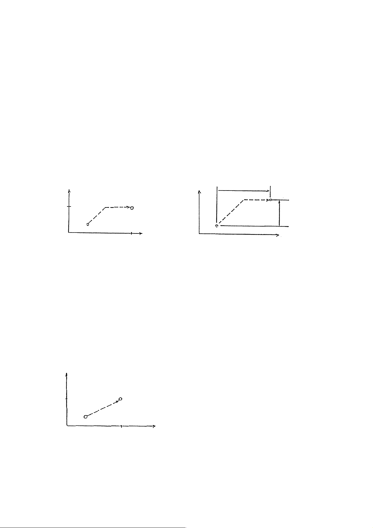
2-1 Positioning (G00)
Each axis moves to a Program-specified position at an independent rapid traverse rate to
perform positioning.
(1) command format
G90
G00 X_ Y_ Z_ ;
G91
(2) Sample program
(a) Absolute programming (b) Incremental programming
G90 G00 X100. Y50. : G91 G00 X100. Y50.
50.
Y
End point
Start point
X
100.
Y
Start point
100.
End point
50.
X
(3) Cautions
(a) The rapid traverse rate has been set independently for each axis.
(b) The tool path is non-linear. See to it that the tool does not interfere with the workpiece.
(c) Linear acceleration/deceleration is applied. Confirm imposition (an accumulated
amount due to servo delay is within tolerance) at the end of the block, and then,
proceed to the next block.
(d) G00, G90 are G91 ale modal G codes. Once they are specified, they remain effective
until the next associated G code is specified.
(e) The tool path can be made linear by altering the parameter.
Y
50.
Start point
End point
X
100.
(f) You can set with the parameter whether the reset state is to be the G00 or G01 mode.
2 - 1
Page 16
(4) Associated parameters
No.1401, # 6 = 0 Dry run made invalid for rapid traverse command.
1 Dry run made valid for rapid traverse command.
No.1401, # 1= 0 Non-linear interpolation as positioning interpolation system
1 Linear interpolation as positioning interpolation system
No.3402, # 0= 0 G00 mode in reset state
1 G01 mode in reset state
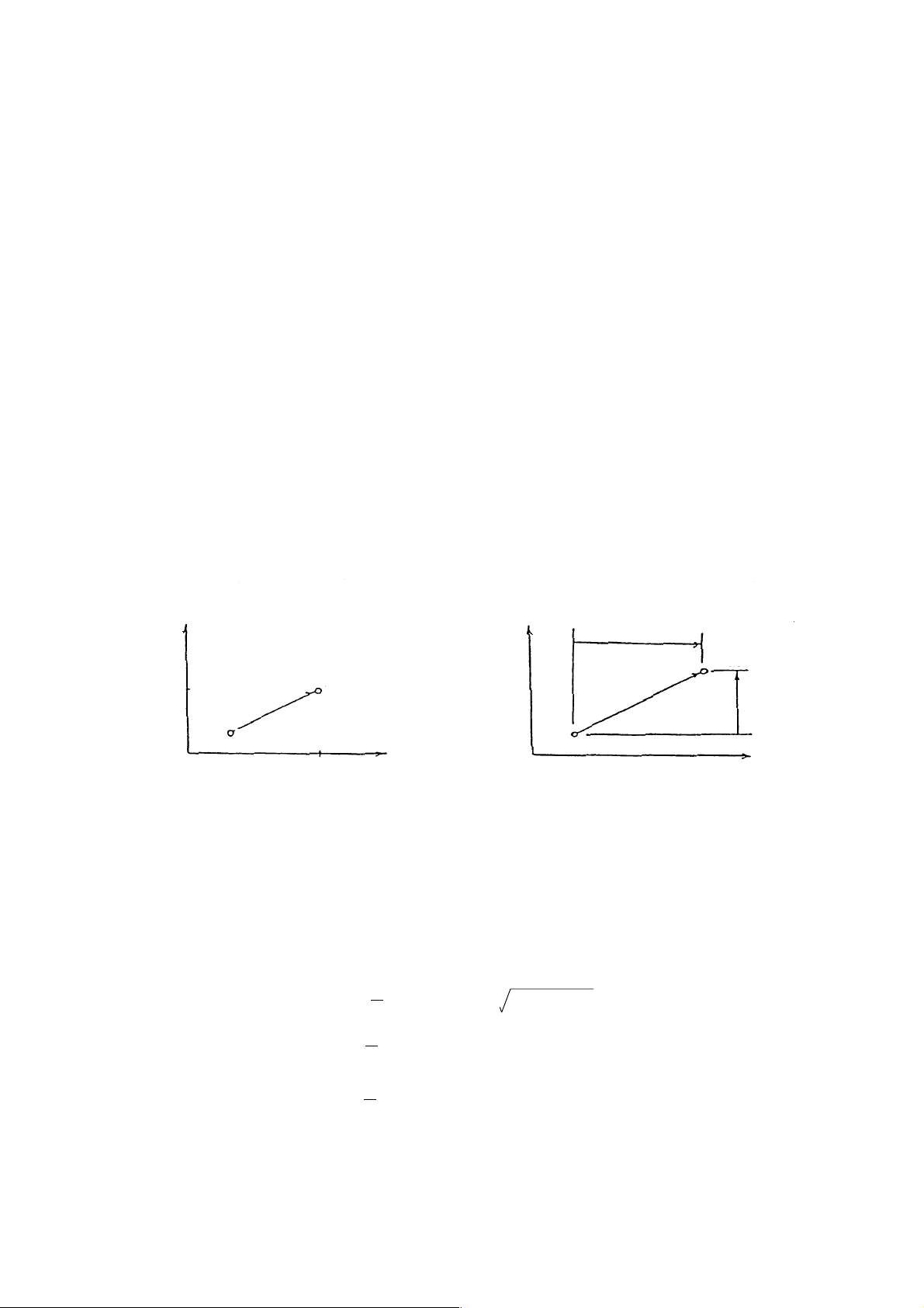
2-2 Linear Interpolation (G01)
The tool moves linearly to a program-specified position at the cutting feed rate specified with an
F code.
(1) Command format
G90
{ }
G91
G01 X_ Y_ Z_...F_ ;
(2) Sample program
(a) Absolute programming. (b) Incremental programming
G90 G01 X100. Y50. F200; G90 G01 X100. Y50. F200;
Y
100.
End point
50.
Start point
50.
Y
End point
Start point
100.
X
(3) Cutting feed rate
The cutting feed rate specified with an F code is the speed at which the tool moves linearly.
In this case, the cutting feed rate is a composite speed of all the specified axes; the cutting
feed rate of each axis is as follows.
X
G01 G91 Xa Yb Zc Ff:
X-axis cutting feed rate: Fx = , where; L= a
Y-axis cutting feed rate: Fy =
z-axis cutting feed rate, Fz =
af
L
bf
L
cf
L
2
+ b2 + c
2
When the rotary axis is specified in the identical block, linear interpolation is performed
taking it as a linear axis in the units of degree.
2 - 2
Page 17

G01 G91 X100. C90. F200 :
End Point
Cutting feed rate in the rotary axis (C axis) direction:
Start
Point
Fc = (deg/min)
where; L = 100.
90. x 200
L
2
+ 90
2
(mm)
(4) Cautions
(a) An alarm results when no F code has been specified in the G01 block or before.
(b) Exponential type acceleration/deceleration is applied.
(c) Set with the parameter whether the reset state is to be the G00 or G01 mode.
(5) Associated parameters
No.3402, #0 = 0 G00 mode in reset state
1 G01 mode in reset state
(6) Associated alarm
No. 102 F0 was specified in the G01/G02/G03 mode.
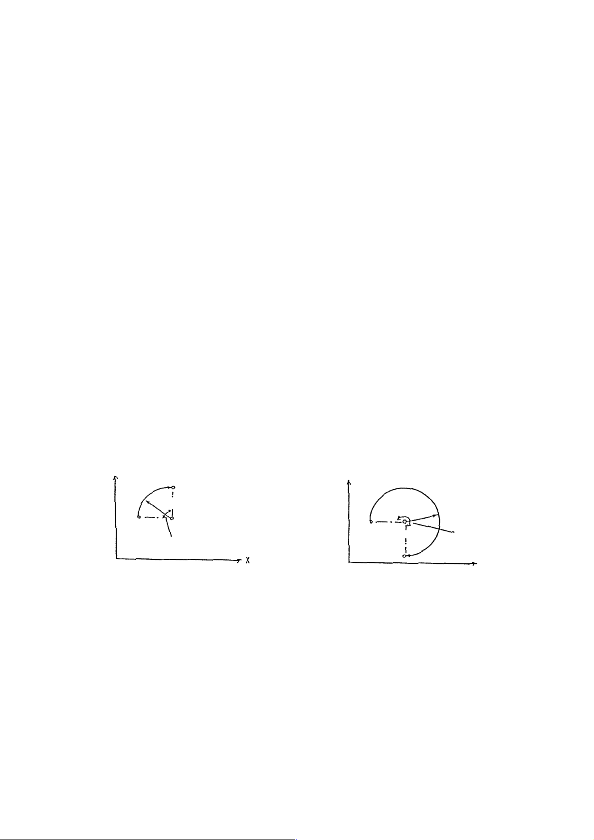
2-3 Circular Interpolation (G02, G03)
The tool moves to a program-specified position along an arc within the plane selected with a
plane selection G code (G17, G18, G19) at the cutting feed rate specified with an F code.
(1) Command format
(a) X
plane
P YP
G02
G17 XP- YP- F_ ;
G03
(b) ZP -XP plane
G02
G18 ZP- YP- F_ ;
G03
(c) XP -ZP plane
G02
G19 YP-ZP- F_ ;
G03
Where; XP : X axis or its parallel axis
Y
Z
(Note) To specify with R instead of I, J or K is called radius designation on arc.
R_
I_ J_
R_
K_ I_
R_
J_ K_
: Y axis or its p arallel axis
P
: Z axis or its parallel axis
P
2 - 3
Page 18
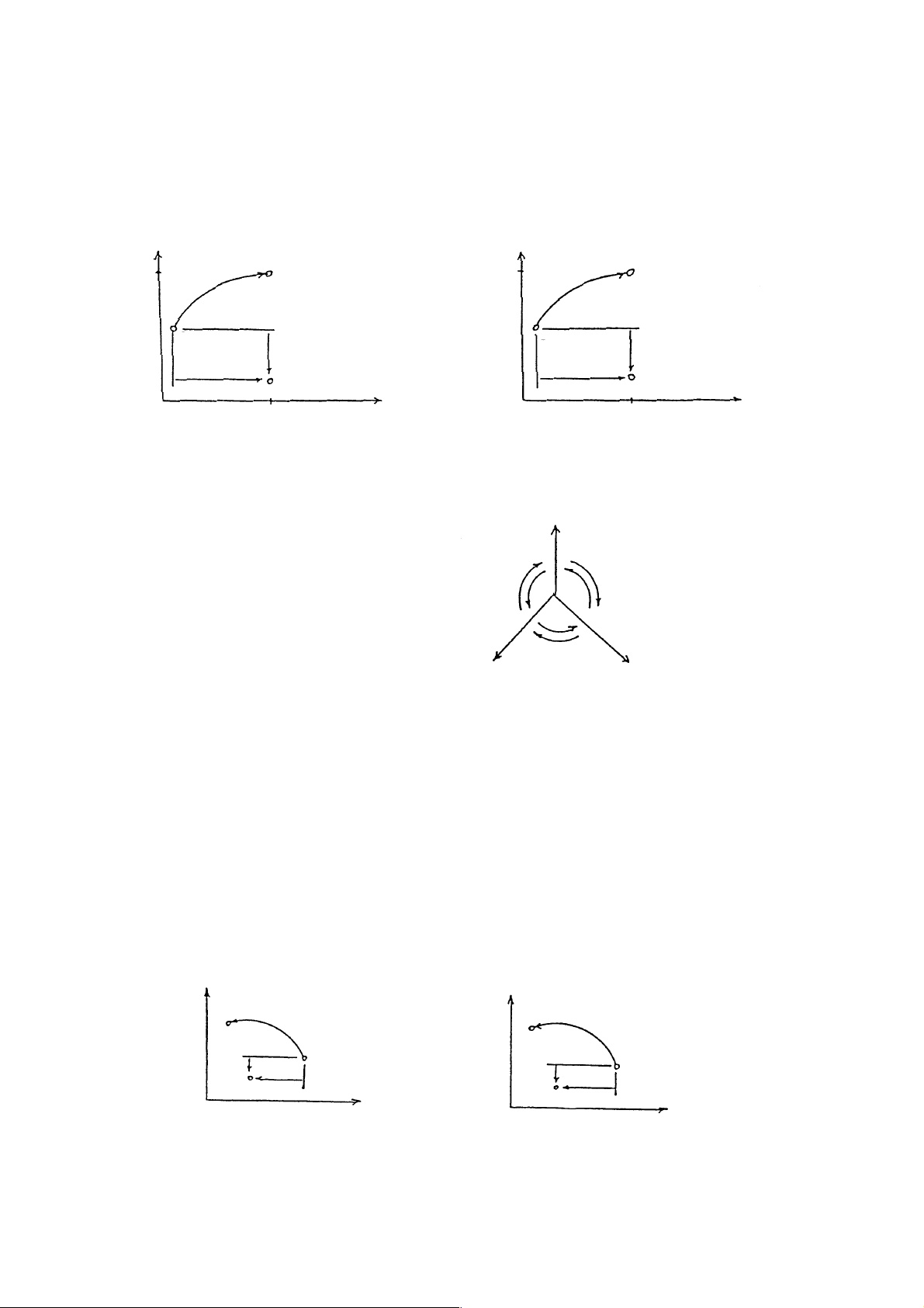
(2) Sample program
(a) Absolute programming (b) Incremental programming
G17 G90 G00 X13.397 Y70. F200: G17 C91 G02 X86.603 Y50
G02 X100. Y120. I86.603 J-50.: I86.603 J-50. F200:
Y
120.
G02
Start point
186.603
End point
J=50
Center
100.
(3) Arc rotating direction
G02 : Clockwise (CW)
G03 : Counterclockwise direction (CCW)
Y
100.
X
G02
X
P
Z
G03
G03
G02
G02
Start point
186.603
P
G03
G02
100.
End point
J=50
Y
P
X
(4) Arc plane
The arc plane is specified with C17, G18 or G19.
G17 : X
G18 : Z
G19 : Y
-YP plane
P
-XP plane
P
-ZP plane
P
(5) Arc center
The arc center is specified with I, J or K corresponding to X
,YP and ZP respectively. In this
P
case, I, J and K are the vector components when viewing the arc center from its start point.
Y
P
End Point
J I
Center point
Start Point
X
P
X
P
End Point
I K
Center point
Start Point
Z
P
2 - 4
Page 19
(6) Cutting feed rate
The cutting feed rate specified with an F code is the speed at which the tool moves on the
arc.
(7) Cautions
(a) An alarm results when no F code has been specified in the G02/G03 block or before.
(b) An alarm results if an arc radius = 0 is specified.
(c) I0, J0 and K0 are omissible.
(d) When there is no end point on the arc, the tool moves linearly the rest after moving
along an arc if the end point error of circular interpolation is within the parameter set
value. Also, an alarm results if it is other than the parameter set value.
End
Point
error
Start Point
End Point
Moves linearly
Center
(e) An alarm results if the axis not for the arc plane is specified.
(f) When R is specified in the same block as I, J and K, R is given priority.
(g) When the rotary axis is specified in the same block, circular interpolation is performed
taking it as a linear axis in the units of degree.
(h) Exponential type acceleration/deceleration is applied.
(8) Associated parameters
No.3459 Arc end tolerance
(9) Associated alarm
No.102 F0 has been command with G01, G02 and G03.
No.132 Arc interpolation error
(#001) Center command, although available, is 0 in value.
(#002) Difference in radius value between of start and end
(#003) pints has exceeded parameter set value.
2-3-1 Radius Designation on Arc
In case of circular interpolation, an arc radius can be directly specified with R instead of
specifying the arc center with I, J or K.
2 - 5
Page 20
(1) Command format.
(a) X
P-YP
plane
G17 X
(b) Z
P-XP
G02
{ }
G03
plane
_ YP _ R ±_ F_ :
P
G02
G18 Z
(c) Y
P-ZP
{ }
G03
plane
_ YP _ R ±_ F_ :
P
G02
G19 Y
{ }
G03
where; X
P-ZP
: X axis or its parallel axis
P
: Y axis or its p arallel axis
Y
P
Z
: Z axis or its parallel axis
P
R+ : Arc of less than 180
R- : Arc of over 180°
(2) Sample program
(a) For the arc of less than 180°
G17 G91 G02 X100. Y100.
R-100. F200:
_ R ±_ F_ :
°
(b) For the arc of over 180°
G17 G91 G02 X100. Y-100.
R-100. F200 :
Y
End Point
R100.
Start
Point
Center
Less than 180°
X
Y
Start
Point
End Point
R100.
Center
(3) Cautions
(a) When I, J, K and R are specified in the same blocks, R is given priority.
(b) When the arc center is not calculated, an alarm results.
G02
(c) When G91 R_ : is specified, it is taken as a block without axial move.
G03
(4) Associated parameters
More than 180°
X
2 - 6
Page 21

(5) Associated alarms
No. 131 An arc radius R with which arc center position cannot be calculated has
been commanded.
2-4 Helical Interpolation (G02, G03)
If an arc command and any one axis for other than arc are specified, helical interpolation is
enabled by control which performs linear interpolation synchronously with arc movement.
(1) Command format
G02
G17 X
G18 Z
G19 Y
where; X
G03
G02
G03
G02
G03
: X axis or its parallel axis
P
: Y axis or its p arallel axis
Y
P
Z
: Z axis or its parallel axis
P
α : Any optional linear axis for other than circulate interpolation (up to 2 axes)
F : Arc speed
Linear axis speed = F
R _
_ YP _ α_ F_ ;
P
_ YP _ α_ F_ ;
P
_ ZP _ α_ F_ ;
P
I _ J _
R _
I _ J _
R _
I _ J _
Linear arc length
×
Arc length
2 - 7
Page 22
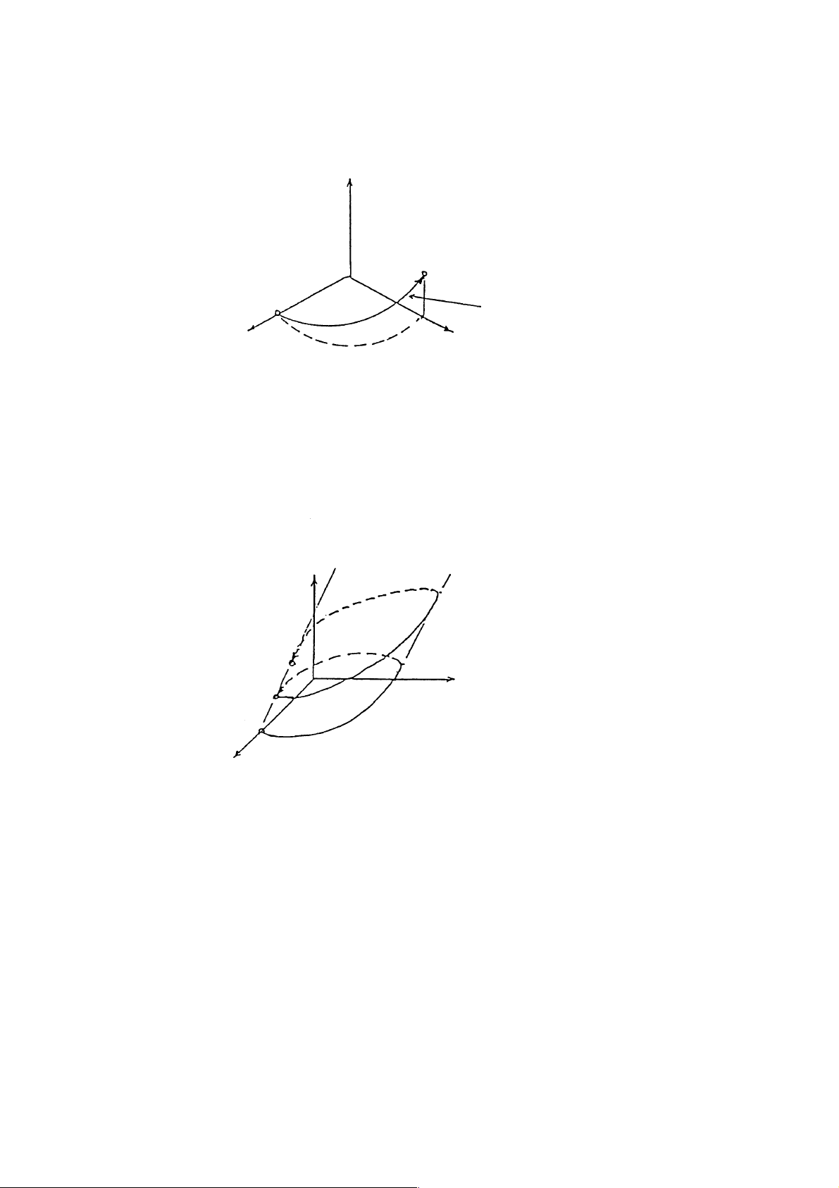
(2) Sample program
G17 G91 G03 X-100. Y-100. R100. Z50. F200 :
Z
End Point
Start Point
X
(3) The axes for other than circular interpolation can be specified up to 2 axes in the same
block.
(Example) G17 G91 G03 I-100. Z100. V50. F200 :
I-100. Z100.V50.;
Z
Tool Path
Y
The V axis must be
parallel with the Y axis.
Y
X
(4) Cautions
(a) See to it that the linear axis speed does not exceed the maximum value.
(b) Tool diameter compensation is applied to circular interpolation.
(c) An alarm results if 3 or more linear axes are specified.
2 - 8
Page 23

(5) Associated parameters
(6) Associated alarms
2 - 9
Page 24

2-5 Virtual Axis lnterpolation (G07)
If the axis is specified as a virtual axis, it does not move.
Interpolation can be perfomed with this axis and other one.
(1) Command format
α 0 ; Sets the α axis as the virtual axis.
G07
: The
: in this section.
G07
α 1 ; Cancels the a axis as the virtual axis.
where ;
(2) Sample program
G07 X0 ; Sets the X axis as the virtual axis.
G17 G91 G02 X0 Y0 I50. Z-1. 0 F200 ; SIN interpolation
G01 X5. F100; Dwell state for the move time of the X axis
G07 X1 ; Cancels the X axis as the virtual aixs.
(3) Cautions
(a) SIN interpolation results if one arc axis for helical interpolation is set as the virtual axis.
(b) The virtual axis is any one axis.
An alarm results if 2 or more axes are set as virtual axes.
(c) If a command is given as to only one axis specified as the virtual axis, the axis move
time valve is placed in the dwell state.
(d) Program virtual axis interpolation in the incremental manner.
Since the virtual axis does not move at any time, it is necessary to be careful when
programming in the absolute manner.
α : Any one axis
α axis is the virtual axis
}
2 - 10
Page 25

(4) Associated parameters
(5) Associated alarms
No.139 Two or more virtual axes have been specified.
2 - 11
Page 26
2-5-1 SIN Interpolation (G02, G03, G07)
SIN interpolation can be performed by assuming one of axes for an arc command as a virtual
axis in helical interpolation.
(1) Command format
G87 α0 ; Sets the virtual axis.
specify helical interpolation.
G07
α1 ; Cancels the virtual axis.
α is any one axis for the arc command.
(2) Sample program
G07 X0;
G17 G91 G03 X0 Y0 I-50. Z100. F200 ;
G07 X1;
Y
Z
(3) Cautions
(a) Effective only for automatic operation of the virtual axis.
(b) Program the virtual axis in the incremental manner.
(c) An alarm results if 2 or more virtual axes are specified.
2-6 Single Direction positioning (G60)
Performs final positioning always from a specified single direction.
Using this function allows you to perform high-accuracy positioning.
(1) Command format
(a) For the one-shot G code
G60 X_Y_Z_... ; Effective only in the G60 specified block
2 - 12
Page 27
(b) For the modal G code
G60 X_ Y_ Z_... ;
X_ Y_ Z_...;
:
Single direction
positioning
:
G00 ;
Cancels G60 if any G code in Group 01
other than G60 is given.
(2) Sample program
(a) When moving in the (b) When moving in the
+ direction - direction
G60 G91 X100.; G60 G91 X-100.;
Start Point
End
Point
Approach
Amount
End Point
Approach
Amount
Start Point
(3) Final positioning direction
Approach amount > 0 : The positioning direction is the + direction.
Approach amount < 0 : The positioning direction is the - direction.
Approach amount = 0 : Positioning is not performed in the - direction.
(4) Cautions
(a) Whether G610 is to be one-shot or modal is set with the parameter.
(b) In the canned cycle, hole positioning is performed with G60.
However, single positioning is disabled for the shift amount of G76 and G87.
(c) During the mirror image, it is disabled for the approach amount of single direction
positioning.
(5) Associated parameters
2 - 13
Page 28

(5) Associated parameters
No. 3458 Single positioning direction and approach amount of each axis
No. 3400, #2 = 0 G60 is the G code of Group 00 (one-shot).
1 G60 is the G code of Group 01 (modal).
2 - 14
Page 29
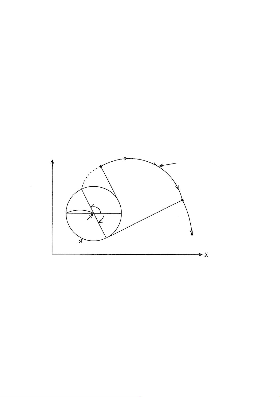
2-7 Involute Interpolation (G222, G223)
This function allows machining along an involute curve. It also provides cutter compensation.
(1) Involute curve
The involute curve in the X-Y plane is defined as following.
θ) =R [cosθ + (θ- θ0) sinθ ] +X0
X(
θ) =R [sinθ + (θ- θ0) cosθ ] +Y0
Y(
where;
X0, Y0:Central coordinate of the basic circle
R : Radius of the basic circle
θ 0 : Angle of the point where the involute curve starts
θ : Angle of the contact of the tangent from the current position to the basic circle
θ ), Y(θ ) :Current position of the X-and Y-axis
X(
Y
Start Point
involute Carve
(X, Y)
R
(X0, Y0)
Basic Circle
The involute curves in the Z-X and Y-Z planes are defined in the same manner as that in the XY plane.
θ 0
θ
End Point
2 - 15
Page 30

(2) Command format
(a) X
_ plane
P -YP
G222
G17 XP _YP _ I_ J_ R_ F_ ;
G223
(b) ZP-XP Plane
G222
G18 ZP _ YP_ K_ J_ R_ F_;
G223
(c) YP-ZP plane
G222
G19 YP_ ZP J_ K_ R_ F_ ;
G223
where;
G222 : Clockwise involute interpolation
G223 : Counterclockwise involute interpolation
X
, YP, ZP: Coordinate value of the end point
P
X
P
Y
P
Z
P
: X-axis or its parallel axis
: Y-axis or its parallel axis
: Z-axis or its parallel axis
I, J, K : Central position of the basic circle for the involute curve viewed from the
R : Radius of the basic circle
F : Cutting feed rate
start point
(3) Start point and end point
The end point of the involute curve is specified with the address X, Y, or Z and expressed
with an absolute or incremental value depending on G90 or G91. If the incremental value is
used, specify the coordinate of the end point viewed from the start point of the involute
curve.
When a start or end point command is within the basic circle, an alarm results. The same
results when an offset vector is brought into the basic circle by cutter compensation.
Care should be taken when an offset is applied, in particular, to the inside of the involute
curve.
(4) Basic circle command
The center of the basic circle is specified with I, J, and K, corresponding to X, Y, and Z,
respectively. However, the numerals following I, J, and K are vector components, when the
center of the basic center is viewed from the start point of the involute curve.
They should be always programmed with incremental values, regardless of G90 or G91.
Add a sign to I, J, and K as required.
2 - 16
Page 31

(5) Feed rate
A feed rate for involute interpolation assumes a cutting feed rate specified with an F-code,
and a speed along the involute curve (speed in the tangent direction of the involute curve)
is controlled to be specified feed rate.
(6) Cutter compensation
Cutter compensation can be applied to the involute curve for perform machining. Cutter
compensation is specified with G40, G41, or G42, like straight line or circular arc.
G40 : Cancels cutter compensation
G41 : Offsets to the left of the tool advance direction
G42 : Offsets to the right of the tool advance direction
Cutter compensation for the involute curve is achieved as follows.
First, obtain a circular arc close to the curvature of the involute curve near the start point of
the involute curve. Similarly, obtain the an intersecting point at offset time near the end
point, and assume the involute curve passing those two points to be a tool center path.
You cannot specify cutter compensation start-up or cancel during the involute interpolation
mode.
(7) End point error
When the end point is not located on involute curve passing the start point, the belowmentioned curve is assumed.
An alarm will result if a shift amount between the involute curve passing the start point and
that passing the end point is greater than a value set in a parameter.
When there is an end point error, a feed rate cannot be assured.
End Point
Corrected Path
Start Point
True Involate Curve
2 - 17
Page 32

(8) Modes available for involute interpolation
Involute interpolation is allowed even during the following G-code modes.
G41 : Cutter compensation to the left
G42 : Cutter compensation to the right
G511 : Programmable mirror image
G68 : Coordinate rotation
(9) Limitations
(a) Rpm of the involute curve
Both start point and end point must be within 100 revolutions from an involute curve
start point. The involute curve revolving one or more time can be also specified in one
block.
(b) Unspecifiable function
Optional angle chamfering corner R cannot be specified during the involute
interpolation mode. Helical interpolation and axis scaling are disallowed.
(c) Modes unavailable for involute interpolation
G411: Normal direction control to the left
G412: Normal direction control to the right
G121: Polar coordinate interpolation
G16 : Polar coordinate command
(10) Associated parameters
No. 3465 Initial angle error limit value for involute interpolation
(1 1) Associated alarms
No. F242 A command value has an error.
1 The start or end point has been specified within the basic circle.
2 I, J, K, or R has been specified with 0.
3 The start or end point is beyond 100 revolutions from the involute curve
start point.
No. F243 The end point is not on the involute curve.
2 - 18
Page 33

2-8 Cylindrical Interpolation (G271)
If the move amount of the linear axis and the angle of the rotary axis are given by a program
command, the move amount of the rotary axis given in terms of angle will be internally
converted into a distance on the circumference. Since the distance on the circumference can
be considered the move amount of the linear axis on the circumference, linear or circular
interpolation can be performed with other linear axis. After interpolation, it will be put back into
the angle of the rotary axis again.
2-8-1 Command Format
G271 A Cylinder radius ; Cylindrical interpolation ON
: Cylindrical interpolation mode
G271 A0 ; Cylindrical interpolation cancel
The A-axis is a rotary axis.
The rotating angle of the rotary axis is calculated back from the move amount on the
circumference. For example; when you want to move by 100.0 on the circumference of the
cylinder whose radius is 50.0, obtain the rotating angle of the rotary axis from the following
formula:
r : Cylinder radius
θ : Rotating angle
s: Move amount on the cylinder
circumference
Rotating angle
2-8-2 Feed Rate
During the cylindrical interpolation mode, a feed rate command F is the speed at which the tool
moves on the outer circumference of the cylinder.
θ=
360 x S (Move amount on circumference)
π x r (Cylinder radius)
2
360 x 10.00
= = 114.591
2
π x 50.0
s
r
θ
Work
2 - 19
Page 34

2-8-3 Cylindrical Interpolation Applied Axes
set in the parameters(no. 3426 for the linear axis, and no. 3427 for the rotary axis) the linear
axis and rotary axis to which you want to apply cylindrical interpolation. A setting range for both
parameters is 1 to the number of controlled axes; they must not have the same value.
2-8-4 Cylindrical Interpolation Applied Plane
During the cylindrical interpolation mode, the plane is automatically selected, which assumes
the rotary axis to be the plane first axis, and the linear axis td be the plane second axis.
2-8-5 Sample Program
(Select the A-Y plane with the parameters 3426 and 3427)
G40 G80 ,.
G00 X-1204.0 Y0 A0 ,.
G01 Z100.0 F100
G271 A50.0 ; Cylindrical interpolation mode ON
N1 G42 G01 X-40.0 F500 ; (Cylinder radius = 50.0)
N2 A90.0 F500 ;
N3 X-100.0 A180.0
N4 A260.0 ; In Cylindrical interpolation mode
N5 G03 X-80.0 A282.918 R20.0 ;
N6 G01 X-60.0 ;
N7 G02 X-40.0 A305.836 R20.0 ;
N8 G01 A360.0 ;
N9 G40 G01X-120.0 ;
G271 AO ; Cylindrical interpolation mode OFF
G00 Z120.0 A0 ;
X
Developed View of Cylindrical Surface with Cylinder Radius = 50.0
A C (Rotary Axis)
Programmed Path
X (Linear
Axis)
Tool Center Path
246.892
282.918
Coordinate Value on
Cylinder Surface
Specified Angle
R: (Cylinder Radius)
2 - 20
Page 35

2-8-6 Cautions
(1) When specifying cutter compensation, start up/cancel during the cylindrical interpolation
mode.
(2) The plane (selected by G17 to G19) existing prior to entering the cylindrical interpolation
mode is canceled once during the cylindrical interpolation mode and revived at the end of
the cylindrical interpolation mode.
(3) When performing circular interpolation during the cylindrical interpolation mode, the method
to specify the circular arc radius (which ones of I, J, and K addresses are to be used) is
determined as follows, depending on the axis of the basic coordinate system to which the
2nd axis (linear axis) of the cylindrical interpolation plane corresponds (setting of the
parameter no. 1011).
• When the linear axis is the X-axis or its parallel axis, specify with K and I, considering it
the Z
p-Xp
plane.
• When the linear axis is the Y-axis or its parallel axis, specify with I and J, considering it
the Xp-Yp plme.
• When the linear axis is the Z-axis or its parallel axis, specify with J and K, considering it
the Yp-Zp plane.
It is also possible to specify a circular arc radius with an R-command.
(4) Specify a G271 command (G271 Axx; ) independently in a block.
If there is no axis command (G271;) after the G271 command, an alarm will result.
(5) If the axis not set in the parameter no. 3427 is specified with the G271 command, an alarm
will result.
(6) The follwing functions are not available:
• Return to the machining break point
• Manual intervention by manual absolute ON
(7) If the follwing comands are given during the cylindrical interpolation mode, an alarm will
result:
• G17, G18, G19 ------------------------ Plane designation
• G28, G30, G53 ------------------------ Machine coordinate system
• G54-59, G540-G599, G92, G52 --- Work coordinate system
• G73, G74, G76, G81-G89 ---------- Canned cycle
• G302-G305, G322-G333 ----------- Special canned cycle
• G00 (when including the cylindrical interpolation applied rotary axis)
2 - 21
Page 36

(8) In the cylindrical interpolation mode, the angle of the rotary axis is converted into the
distance on the circumference and converted back into the angle after interpolation. When
this is done, a slight conversion error results.
(9) If circular interpolation with small circular arc radius is executed during the cylindrical
interpolation mode, a circular interpolation alarm may be caused by the above-mentioned
conversion error. Care should be taken when using it. Even at the time of cutter
compensation, a cutter compensation alarm may result due to the above-mentioned
reason.
(10)If cylindrical interpolation mode ON (G271 Axx; (A
≠ 0) ) is specified again during the
cylindrical interpolation mode an alarm will result.
(11) The residual move amount indicates the value when moving on the outer circumference of
the cylinder.
2-8-7 Associated Parameters
No. 3426 Number of the linear axes(1 to number of controlled axes) to which
cylindrical interpolation is to be applied
No. 3427 Number of the linear axes(1 to number of controlled axes) to which
cylindrical interpolation is to be applied
2-8-8 Associated Alarms
No. 126 A cylindrical interpolation command has an error.
(#001) There is no rotary axis command.
(#002) This is not an independent command.
(#003) The modal G-code is not correct.
No. 127 A wrong command was given during the cylindrical interpolation
mode.
(#001) A wrong G-code was given.
(#003) A rotary axis move command was given in the G00 mode.
(#004) Cylindrical interpolation was specified again during the cylindrical
interpolation mode.
No. 189 (G271) The parameter has not been set properly.
• The parameter no. 3426 or no. 3427 is not "1" to the number of controlled
axes, or they have the same value.
• The linear axis set in the parameter no. 3426 is none of the three basic
axes, X, Y, and Z, or not parallelto awy.
2 - 22
Page 37

2-9 Polar Coordinate Interpolation (G120, G121)
polar coordinate interpolation is a function to provide contour control by converting a command
programmed in the orthogonal coordinate system into a linear axis move(tool move) and rotary
axis move(work rotation).
<Orthogonal Coordinate system> <Polar Coordinate System>
C
(X1,C1)
C
1
C
X
X
X
1
The following shows the relations between (X
, C1 ) and. (X1 ' , C1 ' ).
1
C
1
2-9-1 G Codes
G 121 : Polar coordinate interpolation mode
G 120 : Cancel polar coordinate interpolation mode
2-9-2 Command Format
G121 ; Polar coordinate interpolation mode ON
:
: Polar coordinate interpolation mode ON
:
G120 ; Cancels polar coordinate interpolation mode
(X1’,C1’)
X’
C
X
’
1
X’
X’
2-9-3 Polar Coordinate Interpolation Axes
The linear axis and rotary axis to which you want to apply polar coordinate interpolation should
be set in the parameters (no. 3418 for the linear axis and no. 3419 for the rotary axis) in
advance. For both parameters, set within a range of 1 to the number of controlled axes, and
they must not be of identical value.
2 - 23
Page 38

2-9-4 Polar Coordinate Interpolation plane
A G121 command effectuates the polar coordinate interpolation mode, assumes the zero pint of
the work coordinate system to be that of the coordinate system, and selects the plane(polar
coordinate interpolation plane) which assumes the linear axis to the first axis of the plane and a
virtual axis(rotary axis) orthogonal to the linear axis to be the second axis of the plane. Polar
coordinate interpolation is performed on this plane.
Since polar coordinate interpolation is initiated, assuming the G121 specified position's angle to
be zero (0), regardless of an actual position, prepare a program, assuming the work coordinate
value of the rotary axis to be zero (0) when G121 is specified..
2-9-5 Program Command
(1) In the polar coordinate interpolation mode, specify a program command in terms of
orthogonal coordinate value in the polar coordinate interpolation plane. Use the axial
address of the rotary axis as a command address for the second axis of the plane. The unit
for the command is not degrees; specify in the same unit (rpm or in.) as the linear axis, the
first axis of the plane.
(2) The polar coordinate interpolation mode allows you to specify linear interpolation (G01)
and circular interpolation (G02, G03). Both absolute programming and incremental
programming are allowed.
(3) When performing circular interpolation in the polar coordinate interpolation plane, the
circular arc radius specifying method (whether I, J, or K should be used) is determined as
follow, depending on which axis in the basic coordinate system the first axis (linear axis) of
the plane corresponds to(parameter setting: no. 1011).
• When the linear axis is either X-axis or its parallel axis, I and J are used, assuming the X
-YP plane.
• When the linear axis is either Y-axis or its parallel axis, J and K are used, assuming the Y
-ZP plane.
• When the linear axis is either Z-axis or its parallel axis, K and I are used, assuming the Z
-XP plane.
It is also possible to specify the circular arc radius with an R-command.
(4) Cutter compensation can be applied to the program command. Polar coordinate
interpolation is performed on the profile after cutter compensation. However, specify G121
and G120 in the cutter compensation cancellation mode (G40).
P
P
P
2 - 24
Page 39

(5) For an feed rate, use F-code to specify a tool move rate in the polar coordinate
interpolation plane( orthogonal coordinate system ). Normally, it is specified in feed per
minute (G94); the unit for the F-code will be mm/min. or in./min.
2-9-6 sample Program (X-axis: Linear Axis, C-axis: Rotary Axis)
N1 G00 X50.0 C0 ;
N2 G121 ;
N3 G42 G01 X30.0 F100 ;
N4 C20.0 ;
N5 G03 X20.0 C30.0 R10.0 ;
N6 G01 X-30.0
N7 C-20.0 ;
N8 G03 X-20.0 C-30.0
I0.0 J0;
N9 G01 X30.0;
N10 C0 ;
N11 G40 X50.0 ;
N12 G120 ;
Positions to the start position
Starts polar coordinate interpolation
Profile program(program based on
the orthogonal coordinate value
In the X-C' plane)
Cancels polar coordinate interpolation
Rotaray Axis
Tool
Linear Axis
2 - 25
Page 40

2-9-7 Feed Rate Clamp
The maximum cutting feed rate at polar coordinate interplation can be set in a parameter (no;
3464). If any feed rate higher than this one is specified during polar coordinate interpolation, it
will be clamped to this rate. If a set value is 0, it will be clamped by the normal maximum cutting
feed rate (parameter no. 1422) even during polar coordinate interpolation.
As polar coordinate interpolation converts the profile programmed in the orthogonal coordinate
system into the movements of the linear axis and rotary axis, a move near the work center
(coordinate zero pint) may increase the speed of the rotary axis and exceed the limit speed of
the machine.
If this is the case, the allowable speed of the rotary axis can be set with the parameters as
follows.
Rotary axis allowable speed = Maximum cutting feed rate (parameter no. 3464) x Allowable
ratio(parameter no. 3420)
If the speed component of the rotary axis during polar coordinate interpolation exceeds the
allowable speed, an override calculated by the formula below will be automatically applied.
(Automatic override )
Override = x 100 (%)
If the speed component of the rotary axis stills exceeds the allowable speed even after a
override has been applied, the feed rate will be clamped in such a manner that the speed
component of the rotary axis will not exceed the maximum cutting feed rate. (Automatic speed
clamp)
2-9-8 Rapid Traverse(G00) Operation
A G00 command can be executed during the polar coordinate interpolation mode. to the G00
block, however, only the end point is converted into a position in the polar coordinate system; a
path remains unconverted.
(Example)"AG00 X100.0 C50.0;" in the G121 mode assumes the same path as "G01 X141.421
With G00, the rotary axis takes a short-cut. (move within +/-l80
2-9-9 Precautions
(1) Specify G120 and G121 in an independent block, respectively.
Allowable speed of the rotary axis
Speed component of the rotary axis
C45.0;" in the G120 mode.
° ) to reduce the machining time.
(2) Prior to specifying G121, the work coordinate system must have been set, where the
center of the rotary axis can be the zero point of the coordinate system.
2 - 26
Page 41

(3) The plane prior to G121 (the plane selected with G17, G18,- or- G19) is cancelled once by
specifying G121 and restored by specifying G120.
(4) The following lists the G-codes which cam be specified during the G121 mode.
G00, G01, G02, G03, G04, G09, G40, G41, G42,
G65, G66, G67, G98, G99
(5) Any axis outside the plane in the G121 mode moves independent of polar coordinate
interpolation.
(6) A display of "MOVE AMT." during the G121 mode refers to a remaining move amount in the
polar coordinate plane (orthogonal coordinates). However, the G00 block assumes the
same unit as usual.
(7) The following functions are not available for the block in the G121 mode. Program restart,
Return to machining break point, Manual intervention by manual absolute ON
(8) Upon completion of polar coordinate interpolation (G120) , the work coordinate value of the
rotary axis can be rounded to 360
° through parameter setting. (0° 360°)
<
=
(9) When the work coordinate value of the linear Axis is negative at G121 command. To the
first move block, only the end point is converted into a position in the polar coordinate
system; a path remains unconverted. (Same as linear G00 in the G121 mode)
Starting from the next move block, polar coordinate conversion is applied to the move path.
Only G00 and G01 can be specified in the first move block; G02 and G03 cannot be.
2-9-10 Associated parameters
No. 3410, #1 = 0 Does not Perform automatic override and automatic speed clamp
during the polar coordinate interpolation mode.
= 1 Performs automatic override and automatic speed clamp during the
polar coordinate interpolation mode.
No. 3418 Axis number of the linear axis to which you want to apply polar
coordinate interpolation
No. 3419 Axis number of the rotary axis to which you want to apply polar
coordinate interpolation
No. 3420 Automatic override allowable ratio during the polar coordinate
interpolation mode
No. 3464 Maximum cutting feed rate during the polar coordinate interpolation
mode.
2 - 27
Page 42

2-9-11 Associated Alarms
No. 113 A polar coordinate interpolation command has an error.
(#001) G120 or G121 has not been independently specified.
(#002) When G120 or G121 was specified, cutter compensation had not been
cancelled.
(#003) When the work coordinate value of the linear axis was negative at G121, a
G-code other than G00 and G01 was specified in the first move block.
No. 114 A wrong Command was specified during the polar coordinate interpolation
mode.
(#001) An unavailable G-code was specified.
No. 189 (G121) Parameter Setting is erroneous.
• The setting of the parameters nos. 3418 and 3419 is not within a range of
1 to the number of controlled axes, or the setting of the parameter no.
3418 is equal to that of no. 3419.
• The linear axis set in the parameter no. 3418 is none of the three basic
axes(X, Y, and Z) or not parallel to any of them.
2 - 28
Page 43

3. FEED FUNCTION
3-1 Feed per Minute (G94)
Until G95 is specified after G94 was specified, the stroke per minute (mm/min., inch/min.) is
directly specified with a numerical value following F.
Feed rate F is the stroke per minute
Metric system : mm/min
Inch system : inch/nin.
(1) Command format
G94 ;
(2) Sample program
F100 ; The feed rate is a move of 100 mm per minute.
(3) The F code programmable range is as follows.
(a) Metric system
F60 : 1 ~ 999999 (mm/min.)
F61 : 0.1~999999.9 (mm/min.)
(b) Inch system
F51 : 0.I ~ 99999.9 (inch/min.)
F52 : 0.01 ~ 99999.99(inch/min.)
(5) Cautions
(a) One of F60, F61, F51 and F52 is selected by parameter setting.
(b) then F61 in the metric system is specified without a decimal point, the input
increment of 1 mm/min. or 0.1 m/min. is selected by parameter setting.
(c) In case of thread cutting (G33), feed per revolution is selected, disabling feed per
minute.
(6) Associated parameters
No. 3400, #1= 0 The least input increment for F61 in the metric system without a
decimal point is 1 mm/min.
1 The least input increment for F61 of the metric system without a
decimal point is 0.1 mm/min.
3 - 1
Page 44

No. 3401, #2= 0 F51 for feed per minute in the inch system (inch/min. )
1 F52 for feed per minute in the inch system (inch/min. )
No. 3401, #3= 0 F60 for feed per minute in the metric system (mm/min. )
1 F61 for feed per minute in the metric system (mm/min. )
(7) Associated alarms
3-2 Feed per Rotary (G95)
Until G94 is specified after G95 was specified, the stroke per spindle revolution (mm/rev. inch/
rev.) is directly specified with a numerical value following F.
Feed rate F is the stroke per spindle
revolution
Metric system : mm/rev.
Inch system : inch/rev.
(1) Command format
G95 ;
(2) Sample program
F1, 2 ; The feed rate is 1.2 mm per revolution.
(3) The F code programmable range is as follows.
(a) Metric system
F32 : 0.01 ~999.99 (mm/rev.)
F33 : 0.001 ~ 999.999(mm/rev.)
(b) Inch system
F23 : 0.001 ~ 99.999 (inch/rev.)
F24 : 0.0001 ~ 99.9999 (inch/rev.)
(4) Cautions
(a) One of F32, F33, F23 and F24 is selected by parameter setting.
3 - 2
Page 45

(5) Associated parameters
No. 3401, #0= 0 F23 for feed per revolution in the inch system (inch/rev.)
1 F24 for feed per revolution in the inch system (inch/rev.)
No. 3401, #1= 0 F32 for feed per revolution in the metric system (mm/rev.)
1 F33 for feed per revolution in the metric system (mm/rev.)
3-3 Inverse Time (G93)
when G93 is instructed, the program is put in the INVERSE TIME mode until G94 and G95 are
instructed. Inverse time (FRM) is instructed directly with a value following F.
(1) Command format:
G93 ;
(2) Inverse time (FRN)
(a) For linear interpolation (G01)
FRN = (1/min)
(b) For circular interpolation (G02, G03):
FRN = (1/min)
where; Speed : Metric system (mm/min)
(3) F can be instructed within the following range:
F43 : 0.001 ~ 9999.999
(4) Sample program
G93 ;
G91 G01 X100. F5. ;
Y50. F10.
Speed
Distance
Speed
Distance
Inch system (inch/min)
Distance : Metric system (mm/min)
Inch system (inch)
Spped: 500mm/min
3 - 3
Page 46

(5) Cautions
(a) In G93 mode, F code must be instructed per block.
When F code is omitted, a previously instructed F code becomes valid.
3-4 Exact Stop (G09)
If a G09 command is specified in the same block as a move block, it decelerates and stops the
machine upon completion of one block, and after confirming that the machine position is within
the range in which a command position was specified, proceeds to the next block.
(1) Command format
G09 ------ ;
(2) Sample program
N1 G09 G91 G01 X100. F500 ;
N2 G01 Y-50. ;
The corner has an edge when G09 is specified.
The corner is rounded when G09 is not specified.
(3) Associated parameters
No.1826 Imposition width of each axis
No.1827 Imposition width of each axis on cutting feed
3-5 Exact Stop Mode (G61)
Until G62, G63 or G64 is specified after G61 was specified, this function decelerates and stops
the machine, confirms that the machine position is within the specified range, and then,
proceeds to the next block.
(1) Command format
G61 ;
3 - 4
Page 47

(2) Sample program
N1 G61 G91 G01 X100. F500 ;
N2 Y-50. ;
N3 X - 100. ;
N4 G64;
(3) Cautions
3-6 Automatic Corner Override (G62)
Exact stop effective blocks
The corner has an edge when the G61 mode
is effective.
The corner is rounded when the G61 is
ineffective.
When tool diameter compensation is applied, since the tool center path is located inside the
program-specified path in the inner corner and inner arc area and a cutting load increases, an
override is applied automatically to the cutting feed rate to reduce the cutting load.
Once G62 is specified, it remains effective until G61, G63 or G64 is specified.
(1) Command format
G62 ;
(2) Types of automatic corner override
(a) Automatic override in the
inner corner area.
An overridde is
applied to this part.
Tool Center Path
(b) Inner arc cutting speed change
Programmed Path
Center
Programmed Path
Tool Center Path
3 - 5
Page 48

(3) Cautions
3-6-1 Automatic Override in Inner Corner Area
When the following conditions are met in the corner during the tool diameter condensation
mode, an override is applied to cutting feed automatically.
[ The conditions are as follows for the blocks having the corner between them. ]
(a) When the G code of Group 01 is either G01, G02 or G03.
(b) When an offset amount is other than 0 in the tool diameter offset mode.
(c) When an offset is inside in the corner.
(d) When there is an axis in the offset plane.
(e) When the G41 or G42 is not contained.
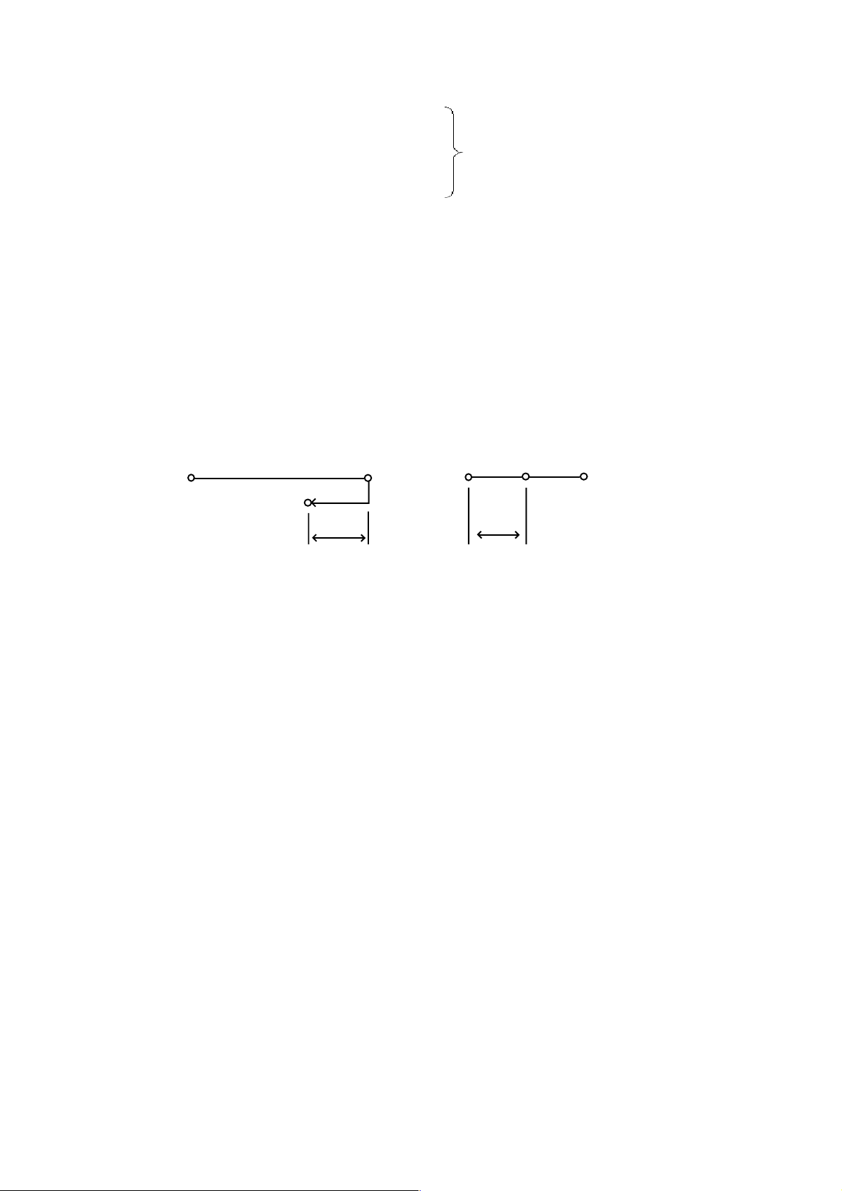
(f) When an inner corner angle is smaller than a parameter set value. (
(g) When a corner start distance and a corner end distance are other than 0 and internal.
(Le, Ls)
p
a
b
θ
An override is applied to cutting feed from the
Center
(1) An override amount for cutting feed is set with the parameter.
<
(Automantic corner override amount) 100 (%)
1
=
An actual cutting feed rate is as follows.
F
× (Automatic corner override amount) × (Feed rate override)
point a through point b.
<
=
where;
θ : Inner criterion angle
Le : Start distance
Ls : End distance
θ)
3 - 6
Page 49

(2) Sample program
(D10 = 10.)
N1 G62 G42 G91 G00 X20. Y50. D10;
N2 G01 X50. F200;
N3 G03 X30. Y-30. R30.;
N4 G64 G40 G00 X20.;
(3) Cautions
(4) Associated parameters
No. 1711 Inner criterion angle of automatic corner override
No. 1712 Override amount of Automatic corner override.
No. 1713 Start distance of automatic corner override
No. 1714 End distance of automatic corner override
An override is
applied from the point
a though point b.
(5) Associated alarm
3-6-2 Inner Arc Cutting Speed Change
When arc cutting is offset inside during the tool diameter compensation node, an override of the
ratio of radius of the tool diameter center path to that of the programmed path is applied to the
specified cutting feed rate.
The cutting speed in the tool diameter center path is as follows.
Rc
Fx where; Rc : Radius of the tool center path
Rp
Rp : Radius of the programmed path
Programmed Path
Tool Center Path
Center
3 - 7
Page 50

(1) Sample program
N1 G62 G41 G91 G00 X50. D10;
N2 G03 Y50. J25. F200;
N3 C64 G40 G00 X-50.;
Override is
aplied to the
N2 block
(2) Cutting feed rate when automatic corner override overlaps inner arc cutting
Rc
F x x (Automatic corner override) x (Feed rate override)
Rp
(3) Cautions
(a) By parameter setting, inner arc cutting speed change can be enabled regardless of the
G62 mode.
(b) When the value of Rc/Rp is smaller than the parameter set value, the minimum
deceleration ratio of the parameter set value is used.
(4) Associated parameters
No. 3406, #0 = 0 Inner arc cutting speed change is regardless of the G62 mode.
1 Inner arc cutting speed change is enabled in the G62 mode.
No. 1710 Minimum deceleration ratio of the inner arc cutting speed
(5) Associated alarms
3 - 8
Page 51

3-7 Tapping Mode (G63)
The control state of the NC unit is as follows until G61, G62 or G64 is specified after G63 is
specified.
(a) Cutting feed rate override fixed at 100 %.
(b) Feed hold disabled
(c) Spindle override fixed at 100 %
(a) Single block disabled
(e) Decelerated stop disabled at the joint of the blocks (imposition check disabled)
(f) Tapping mode signal output
(g) Dry run disabled
(1) Command format
G63 ;
(2) Sample program
N1 G63 G91 G01 X10. F200 ;
N2 Z -30. ;
N3 Z30. ;,
N4 X10. ;
N5 Z - 30. .;
N6 Z30. ;
N7 G64 X10 ;
Tapping mode effective blocks
(3) Cautions
(a) By Parameter setting, you can invalidate dry run disabled.
(4) Associated parameters
No.1401, #5= 0 Disables dry run for thread cutting and tapping commands.
1 Enables dry run for thread cutting and tapping commands.
3 - 9
Page 52

3-8 Cutting Mode (G64)
Until G61, G62 or G63 is specified after G64 was specified, the program makes the next block
executed continuously without decleration to a stop between the blocks.
When cutting is performed in the G64 mode, the corner may be rounded at the time of cutting
feed.
Programmed Path
Actual Tool Path
(1) Associated G code
G61 Exact stop
G62 Automatic corner override
G63 Tapping mode
G64 Cutting mode
(2) Cautions
(a) The G64 mode is set in the reset state.
(b) A G00 command decelerates the machine to a stop regardless of the G64 mode.
3 - 10
Page 53

3-9 Automatic Acceleration/Deceleration
As post-interpolation acceleration/deceleration apply automatically to all commands, no special
consideration is necessary.
Rapid traverse (G00, ) : Linear type acceleration/deceleration
Cutting feed (G01, G02, G03, ) : Exponential type acceleration/deceleration
[Linear type acceleration/deceleration ] [Exponential type acceleration/deceleration ]
(a) For rapid traverse, acceleration/deceleration is always pefformed every one block.
(b) For cutting feed, acceleration/deceleration is performed continuously instead of every
one block.
(2) Cautions
(a) Optimal values for parameters relating to acceleration/deceleration control have been
set for each machine
(b) For cutting feed, acceleration/deceleration is performed continuously instead of every
one block.
3-10 Dwell (G04)
When specifying by time: A G04 command causes the machine to wait for the time
When specifying by revolutions: A G04 command causes the machine to wait for the
(1) Command format
(a) When specifying by time
G94 G04 ;
P_or X_ : Dwell time (0.001 to 99999.999 sec.)
(b) When specifying by revolutions
G95 G04 ;
P_or X_ :Spindle rotation angle (0.001 to 9999.999 rev.)
specified with the address P or X and delays switching to
the next block by this time.
spindle rpm specified with the address P or X And delays
switching to the next block for this time.
P _
{ }
X_
P _
{ }
X_
3 - 11
Page 54

(2) Sample program
G94 G04 P2000 ; Dwell time 2 seconds
G04 X2. ; Dwell time 2 seconds
(3) Cautions
(a) By parameter setting, you can specify by time even during the feed per revolution
mode.
(4) Associated parameters
Not 3400, #5 = 0 G04 always specifies by time.
1 G04 follows G94 or G95.
3 - 12
Page 55

4. REFERENCE POINT
4-1 Automatic Reference Point Return (G28)
After positioning the axes specified by the program to the intermediate point, a G28
command can automatically return them to the 1st reference point.
(1) Command format
G28 X_Y_Z_... ;
(2) Sample program
G28 G91 X-50.Y100. ;
Intermediate Point
(Positioning)
(Positioning)
Start Point
1st Reference Point
(3) When G28 is specified without completing manual reference point return after turning on
the power.
After positioning the program-specified axes to the intermediate point, reference point
return is performed automatically in the same sequence as manual reference point return.
When OT(overtravel) occurs before completing reference point return, the axes retract by
the amount set with the parameters and perform reference point return again.
(4) Cautions
(a) The G28 command onward is high-speed return after completion of reference point
return.
(b) The G28 command makes a reference point return check upon completion of high-
speed return, and if the axes have not returned, an alarm results.
(c) If G90 G28 G53 X_Y_Z ..., is specified, the axes are positioned to the position
specified with G53, and then, they return to the reference point.
(d) The G28 command confirms imposition upon return to the reference point.
4 - 1
Page 56

(5) Associated parameters
(6) Associated alarms
4-2 Reference Point Return Check (G27)
After positioning the axes to the program -specified position, a G27 command checks whether
they have returned to the 1st reference point, and when they have not returned to the 1st
reference point, an alarm results.
(1) Command format
G27 X_ Y_ Z_ ... ;
(2) Sample program
G27 G91 X100. Y-50. ;
After the X axis and Y axis moved by 100 and - 50, respectively, it is checked whether they
have returned to the 1st reference point.
(3) Cautions
(a) The position reached with a G27 command has tool length compensation, tool offset
and tool diameter compensation amounts added to it.
(b) Only the axis specified in the G27 block is checked whether it has returned.
(c) The 2nd to 4th reference point return check is possible.
G27 P_ X_ Y_ Z_ ... ;
Where; P2 - P4 : Specify corresponding to the 2nd through 4th reference points.
(d) The axis for which the machine lock function is turned on has no position check
conducted on the reference point.
(e) The G27 command confirms imposition upon return to the reference point.
4 - 2
Page 57

(4) Associated parameters
(5) Associated alarms
4 - 3
Page 58

4-3 Return from Reference Point (G29)
A G29 command positions the program-specified axes from the reference point to the
intermediate point of G28 or G30 specified just before, and then, positions them to the specified
position.
(1) Command format
G29 X_Y_Z_... ;
(2) Sample program
N1 G28 G91 X-50. Y100. ;
N2 G29 G91 X50. Y50.;
Y
N2(G29)
Intermediate Point
N2(G29)
N1(G28)
Reference Point
(3) Cautions
(a) If G29 is specified with no G28 or G30 specified once, the intermediate point becomes
zero.
N1(G28)
X
4 - 4
Page 59

4-4 2nd-4th Reference Point Return (G30)
A G30 command can automatically return the axes specified in the program to the 2nd to 4th
reference point after positioning them to the intermediate point. The 2nd, 3rd, and 4th reference
points are the positions specific to the machine and set with the parameters.
(1) Command format
P2
P3
G30 X_ Y_ Z_ ...;
{ }
P4
where; P2 : 2nd reference point return
P3 : 3rd reference point return
P4 : 4th reference point return
Default : 2nd reference point return
(2) Sample program
G30 G91 P3 X-50. Y100.; Y
Y
3rd Reference Point
(3) Cautions
(a) The G30 command confirms imposition upon return to the reference point.
(b) If G90 G30 G53 P_X_Y_Z_...; is specified, the axes are positioned to the position
specified with G53, and then, returned to the 2nd - 4th reference point.
Intermediate Point
Start Point
X
4 - 5
Page 60

(4) Associated parameters
No. 1226 2nd reference point of each axis
No. 1227 3rd reference point of each axis
No. 1228 4th reference point of each axis
(5) Associated alarms
4 - 6
Page 61

4-5 Reset of Floating Reference point (G301)
G301 instruction may be automatically reset to the following reference point after an axis
instructed by the program is positioned at a middle point.
The floating reference point is a selected point on the machine.
The floating reference point can be set in accordance with the following procedure:
1 Pressing the POSITION key selects the position screen.
2 Pressing F6 and Y keys set a present position of the polar coordinate system as a
floating reference point.
(1) Command format
G301 X_Y_Z... ;
(2) Sample program
G301 G91 X-50. Y100 ;
Y
Floating Reference Point
(3) Cautions
(a) G301 instruction checks In-Position when reset to the floating reference point.
(b) G90, G301, G53 and X_Y_Z resets the floating reference point after positioning them
to G53 instruction.
(4) Associated parameters
No. 1229 Floating reference point of each axis.
Middle Point
Start Point
X
4 - 7
Page 62

4 - 8
Page 63

5. COORDINATE SYSTEM
5-1 Machine Coordinate System Selection (G53)
When a G53 Command, the axes are positioned to the position of the machine coordinate
system specified by the program.
(1) Command format
G90 G53 X_ Y_ Z_... ;
(2) Sample program
G90 G53 X20. Y10. ;
Y
End
10.
Point
Machine Coordinate System
(3) Cautions
(a) An alarm results if this is specified in the G91 mode.
(b) Specify this after cancelling tool diameter compensation.
(c) The G53 command is effective only in the block where it is specified.
(d) The G53 command confirms imposition at the end point of the block.
(4) Associated parameters
(5) Associated alarms
No. 146 Machine coordinate system selection was specified in the G91 mode.
Y
20.
(G00)
Start Point
X
Work Coordinate System
X
5 - 1
Page 64

5-2 Work Coordinate system selection (G54 - G59)
Six peculiar coordinate systems can be set by specifying G54 - G59, respectively. Before
specifying G54 - G59, set the offset amount (machine coordinate system position when the tool
nose is positioned to the zero point of the work coordinate system) from the machine zero point
to the zero point of each work coordinate system.
(1) Command format
G54 ; Work coordinate system 1 selection
C55 ; Work coordinate system 2 selection
C56 ; Work coordinate system 3 selection
G57 ; Work coordinate system 4 selection
G58 ; Work coordinate system 5 selection
G59 ; Work coordinate system 6 selection
G54 Work
Coordinate
System
G54
Offset
Amount
Machine Coordinate System
Amount
G55 Work
Coordinate
System
G55
Offset
Amount
(2) Sample program
N1 G54 G90 G00 X0 Y0 ;
where; G54 offset amount is;
X - 200.
Y - 250.
This Command positions the axes to
(0, 0) of the work coordinate system;
the then position of the machine
coordinate system is (-200., -250.).
Offset
G56 Work
Coordinate
System
G56
Amount
Offset
G57
Machine
Coordinate System
Start Point
G54 Work
Coordinate System
G57 Work
Coordinate
System
Offset Amount
G59 Offset Amount
N1
G58
-200
(0.0)
G58 Work
Coordinate
System
G59 Work
coordinate
system
Y
X
G54
Offset
Amount
250
5 - 2
Page 65

(3) Cautions
(a) The G54 work coordinate system is selected in the reset state.
(b) The G54 coordinate system is set upon completion of zero point return.
(c) When the offset amount of the work coordinate system is changed, the new work
coordinate system is set when corresponding G54 - G59 is specified next time.
(d) When G54 - G59 is specified after setting the new coordinate system with a G92
command, the zero point of the machine coordinate system and the offset amount of
the G54 - G59 work coordinate system are changed relatively by the amount set newly
with G92.
(e) When establishing the G54 - G59 work coordinate system after specifying G92, it is
necessarily to specify manual zero point return or G921 (work coordinate system
preset) in the reset state.
(f) Set the G54 through G59 offset amounts in the work coordinate screen.
5-3 Addition of Work Coordinate system Pairs (G540 - G599)
Sixty peculiar coordinate systems can be set by specifying G540 - G599, respectively.
Before specifying G540 - G599, set the offset amount (machine coordinate system position
when the tool nose is positioned to the zero point of the work coordinate system) from the
machine zero point to the zero point of each work coordinate system.
(1) Commad format
G540 ; G540 work coordinate system selection
G541 ; G541 work coordinate system selection
C542 ; G542 work coordinate system selection
::
::
G599 ; G599 work coordinate system selection
Offset
G541 Work
Coordinate
System
G541
Offset Amount
G540 Work
Coordinate
System
G540
Offset
Amount
Amount
G542 Work
Coordinate
System
G542
G599 Work
Coordinate
System
G599
Offset Amount
Machine Coordinate System
5 - 3
Page 66

(2) Sample program
NI G540 G90 G00 X0 Y0;
where; G540 offset amount is;
X - 210.
Machine
Coordinate
System
-210.
Y
Y - 260.
This command positions the
axes to (0, 0) of the work coordinate
Start Point
N1
system; then the position of the
machine coordinate system will be
(-210., -260.).
G540 Work
Coordinate System
-260.
(3) Cautions
(a) G540 through G599 aid G54 through G59 are the G codes of the same group.
(b) When G540 - G599 is specified after setting the new coordinate system with a G92
command, the zero point of the machine coordinate system and the offset amount of
the G540 - G599 work coordinate system are changed relatively by the amount set
newly with G92.
(c) When establishing the G540 - G599 work coordinate system after specifying G92, it is
necessary to specify manual zero point return or G921 (work coordinate system
preset) in the reset state.
(f) Set the G540 through G599 offset amounts in the Work Coordinate screen.
X
5 - 4
Page 67

5-4 Local Coordinate System Setting (G52)
One additional coordinate system can be set in the selected work coordinate system by
specifying G52.
(1) Command format
G54 X _ Y _ Z _... ; Local coordinate system setting
Offset Amount of Local Coordinate System Setting
Local
Coordinate System
Local Coordinate
System Offset Amount
Work Coordinate System
Work Coordinate System Offset Amount
Machine Coordinate system
G52 X0 Y0 Z0...; Local Coordinate System Setting Cancel
(2) Sample program
N1 G54 ;
N2 G52 X-150. Y-100.;
N3 G90 G00 X0. Y0.;
where; G54 offset amount;
Machine
Coordinate System
-350.
-200.
X - 200.
Y - 250.
Executing the N1 block sets the G54
work coordinate system.
Executing the N2 block sets the local
coordinate system.
Executing the N3 block positions the
axes to (0, 0) of the local coordinate
Start Point
N3
G54
Work Coordinate
System
Local
Coordinate
System
-150.
(0, 0)
Offset
Amount
(0, 0)
Local Coordinate
System Offset Amount
-100.
system; the then position of the
machine coordinate system will be
(-350., -350.).
(3) Rotation of the offset amount
When the local coordinate system is set during the coordinate rotation (type A) mode, the
offset amount rotates. However, rotation of the offset amount is not cancelled even if
coordinate rotation is cancelled by specifying G69.
When the local coordinate system is set during coordinate rotation, cancel the local
coordinates first and then, cancel coordinate rotation.
Y
X
G54
-250.
-350.
5 - 5
Page 68

(4) Cautions
(a) In the reset state, the local coordinate system A is cancelled.
(b) The local coordinate system of the axis specified with G92 is cancelled.
(c) An alarm results if G52 is specified during the tool diameter compensation mode.
(d) G52 is a one-shot command. The local coordinate system created with G52 remains
effective until next G52 is specified.
(5) Related parameters
No. 1200, #0 = 0 The offset Amount of the local coordinate system rotates.
1 The offset amount of the local coordinate system does not rotate.
5 - 6
Page 69

5-5 Work Coordinate System Change (G92)
By specifying G92, you can create the coordinate system on the program without using the G54
-G59 of G540 - G569 work coordinate system.
(1) Command format
G92 X_Y_Z...;
Position to Specify Current Position in G92 Work Coordinate System.
G92 Command Position
Old Work
Coordinate System
Machine Coordinate System
Y
Work Coordinate System by G92
Command
Y
Y
(2) Sample program
N1 G90 G00 X50. Y50. ;
N2 G92 X150. Y200. ;
Executing the N2 block creates
the work coordinate system in
which the current position will
be (150., 200.).
200.
50.
(0, 0)
Machine Coordinate System
G92 Command Position
(0, 0)
50.
Old Work
Coordinate
System
Work Coordinate
150.
System by G92
Commamd
X
X
X
(3) When G92 is specified with the G54 - G59 or G540 - G599 work coordinate system
established;
The G92 command shifts all of the G54 -G59 and G540 - G599 work coordinate systems
which are based on the machine coordinate system.
5 - 7
Page 70

(4) Cautions
(a) G92 is a one-shot command.
(b) G92 has nothing to do with absolute (G90)/incremental(G91) programming.
(c) If G92 is specified while tool diameter compensation, tool length compensation or tool
offset is applied, the coordinate system is set as if G92 is specified at the position prior
to compensation.
(d) The local coordinate system of the axis specified with G92 is cancelled.
(e) There are two methods available for invalidating the work coordinate system with the
G92 command.
(i) Perform manual zero point return inthe reset state.
(ii) Specify G921 X0 Y0 Z0... ; (work coordinate system preset).
5 - 8
Page 71

5-6 Work Coordinate System Preset (G921)
If you perform first manual reference point return after turning on the NC unit, the machine
coordinate system is set, and then, the work coordinate system is set.
Manual reference point return in the reset state sets the work coordinate system. The work
coordinate system is shifted from the machine coordinate system by the following command or
operation. In this case, it is called "work coordinate system preset" to set the work coordinate
system again based on the machine coordinate system.
(a) When a manual absolute signal is turned off and manual operation intervenes.
(b) When an axis move command is specified in the machine lock mode.
(c) When moving the axes by handle interrupt or manual automatic simultaneous
operation.
(d) Work coordinate system shift with the G92 command.
(e) Work coordinate system origin by MDI operation.
G54(or other) Work coordinate
System and G54(or other) Work
Coordinate system after Work
Coordinate System Preset.
Shift by
G92
Machine coordinate System
(1) Command format/operation
(a) By the G code
G921 X0 Y0 Z0 ...;
Work Coordinate System Preset Axes
(b) By operation
Perform manual reference point return in the reset state (OP signal OFF).
G54(or other) Work
Coordinate System
Shifted by G92
Shift by Work Coordinate Preset
5 - 9
Page 72

(2) Cautions
(a) Using a G921 Command cancels tool diameter compensation, tool length
compensation and tool offset.
(b) By parameter setting, the work coordinate system can be preset just before executing
the first block in which the machine is switched over from the reset state to automatic
operation.
(3) Associated parameters
No. 1202, #0 Presetting of work coordinate system on recovery of manual
reference point is:
=0 Carried out in reset state.
=1 Carried out in any circumstance.
No. 1202, #2 Presetting of work coordinate system on recovery of manual
reference pint:
=0 Follows #0 of Parameter No. 1202.
=1 No presetting takes place for any axis.
No. 1202, #3 Work coordinate system, on starting of auto operation following reset
state :
=0 Does not perform presetting.
=1 Performs presetting.
(Note 1) When "presetting takes place in any circumstance" (No.2403, #0=1) has been set,
processing is carried out only when no pre-read block exists and a execution block
has been completed.
(4) Associated alarms
5 - 10
Page 73

5-7 Work Coordinate System Shift (External Work Zero Point Offset Amount)
The entire G54 or other work coordinate system can be shifted by the specified amount
(external work zero point offset amount) by setting an offset amount in the external offset of the
work coordinate system in the NC screen.
G54 Work
Coordinate
System
External Work Zero
Point Offset Amount
Machine Coordinate System
G55 Work
Coordinate
System
G599 Work
Coordinate
System
G599 Offset Amount
(Note 1) When the external work zero point offset amount is changed, it becomes effective
from the block where the G54 or other work coordinate system is specified.
(Note 2) If set to parameter No. 1201, #0.= 1, enabled as soon as the external work origin
offset amount is changed.
5 - 11
Page 74

5-8 Plane Selection (G17, G18, G19)
With a G17, G18. or G19 Command, this function specifies the plane in which an arc
command, tool diameter compensation, coordinate rotation, etc. are performed.
(1) Command format
G17 X
G18 Z
G19 Y
G17 ; X-Y plane
G18 , Z-X plane
G19 ; Y-Z plane
(2) Sample program
G00 G91 ;
G17 U0 Y0; Selects the U-Y plane.
G00 G91 ;
G18 W0 X0; Selects the W-X plane
_ YP _; XP-YP plane
P
_ XP_; ZP-XP plane
P
_ ZP_; YP-ZP plane
P
where; XP: X axis or its parallel axis
: Y axis or its parallel axis
Y
P
Z
: Z axis or its parallel axis
P
:
: The U-Y plane is effective.
:
:
: The W-X plane is effective.
(3) Cautions
(a) Set with the parameter with which one of the X, Y and Z axes the additional axis is
parallel.
(b) Set with the parameter whether the reset state is to be the G17 or G18 mode.
(c) An alarm results when the plane is not determined in the block where G17, G18 or
G19 was specified.
(Example) G17 X_ U_ Y_ ; It is uncertain whether the X-Y or U-Y plane is selected.
(d) A move command is irrelevant to plane selection.
5 - 12
Page 75

(4) Associate parameters
No. 3402, #5 =0 The reset state is the G17 mode
1 The reset state is the G18 mode
(5) Associate alarms
No. 106 A plane seleection (G17 - G 19) commend has an error.
5 - 13
Page 76

5-9 Rotary T able Dynamic Fixture Offset
When loading a workpiece on the rotary table and set a work coordinate system after
measuring a position of workpiece if the rotary table has rotated before starting cutting, the
work coordinate system should be set again by measurement of a position of workpiece once
more.
However, if a position of workpiece at a certain position of the rotary table is set at the standard
fixture offset amount, even if the rotary table rotate, calculate a fixture offset amount at this time
automatically from an angle of the rotary table and make a work coordinate system according
to this value. In view of these facts, if a position is set once at the standard fixture offset
amount, the work coordinate system can be held dynamically corresponding to a position even
if The rotary table rotates any position.
A position adding a work reference point offset amount on the fixture offset amount on the
fixture offset amount becomes the work coordinate reference point.
(1) Setting of data.
1 Three-piece set of parameter designated a rotary axis and two linear axes constructed
a rotary plane.
In each set, the 1st parameter is for a rotary axis number, and the 2nd and 3rd ones for
linear axis numbers. Set the two linear axis numbers so that rotation from the positive
direction of the 2nd linear axis to that of the 3rd linear axis will be positive directional
rotation of the 1st rotary axis.
To calculate a fixture offset amount, calculate it for the rotary axis of the 1st set, and
then, calculate it for the 2nd and 3rd sets with respect to that result. If you do not need
as many as 3 sets, set 0 for the rotary axis.
When there are two or more rotary axes and the rotating plane is changed by other
rotation, set the rotating plane when the position of the rotary axis is 0 degree.
2 Standard fixture offset amount at the standard angle of rotary axis. Set a certain
position of rotary axis (standard angle) and a fixture offset amount at the time. Setting
is done by the fixture offset screen. Number of sets are 8 sets.
5 - 14
Page 77

Y
W : Work Shift Amount
F : Fixture Offset Amount at
F’
F
X
Reference Angle
C
Machine Zero Point
3 Parameter for effective/ineffective of fixture offset for each axis (No. 1208, #0)
Set 1 for the axis to be effective of fixture offset.
4 Type of fixture offset (No.1200, #1)
When a vector of fixture offset has changed (command of G522 or when a rotary axis
is moved during a command of G522),set whether a changing amount of vector is
moved or not moved.
When it is 0, it moves. (Work coordinate is not changed and machine coordinate is
When it is 1, it does not move. (Work coordinate is changed and machine coordinate
(2) Command form
G522 Pn ;
n : No. of fixture offset amount (1-8)
By a command of G522 Pn ;,calculate a fixture offset amount by a present rotary angle and
a data designated by n and make the fixture offset amount effective.
By a command of G522 P0 ;,make the fixture offset amount ineffective.
Also, if a rotary axis which is related a fixture offset during G522 mode is moved, execute
a calculation of vector again.
W
changed.)
is not changed.)
5 - 15
Page 78

(3) Program example and notion
parameter No.1285 4 (C axis)
No.1286 1 (X axis) No.1208, #0 (X) =1 (X axis is effective)
No.1287 2 (Y axis) No.1208, #0 (Y) =1 (Y axis is effective)
Data of n= 1 X = -10.0
Y=0
C = 180.0 (standard angle)
C=180
(Reference Angle)
N2
C=90
N4
N5
N3
C
[N3]
Y
Center of Rotation
X
Work coordinate
value
Machine coordinate
value
Fixture offset
amount
Program X Y C X Y C X Y C
N1 G90 G00 X0 Y0 C90.;0 0 90. 0 0 90. 0 0 0
N2G 522 P1 0 0 90. 0 10. 90. 0 10. 0
[ 0 -10. 90. 0 0 90. 0 10. 0 ]
N3 G01 X10. Y2. F100; 10. 2. 90. 10. 12. 90. 0 10. 0
N4 G02 X2. Y10. R10.; 2. 10. 90. 2. 20. 90. 0 10. 0
N5 G01 X0 Y0,. 0 0 90. 0 10. 90. 0 10. 0
In the bracket show #1 = 1 of parameter 1200
(4) Motion at reset
At the time of reset, whether the fixture offset is cancelled or not is according to the #2 of
parameter 1200.
When it is 1, a vector before reset is held.
When it is 0, a vector is cleared. However, the machine does not move for a vector cleared.
5 - 16
Page 79

(5) Screen of fixture offset
To select the Fixture offset screen, use F6/FIXTURE OFFSET or F4/WORK
COORDINATE .
ACT at the upper left of the screen displays the currently selected fixture offset number (P)
and fixture offset vector.
(6) Input/output of fixture offset amount
Setting and input/output of data in a program with outside is available.
(a) Setting of standard fixture offset amount by G10
Standard fixture offset amount or standard angle in a program can be set.
G10 L22 P_ X_ Y_ Z ... ;
P1 - P8 : Fixture offset No.
X, Y, Z... : Standard fixture offset amount or standard angle of each axis.
When it is executed in the G90 mode, a value itself is set.
When it is executed in the G91 mode, a value add on the previous value is set.
(7) Precautions
(a) A command of G522 and rotary axis related a fixture offset during a command of G522
is restrained a buffering.
5 - 17
Page 80

(b) If a parameter or standard fixture offset amount are changed during the G522 mode, it
becomes effective after a command of next G522.
(c) If the following command is executed for a rotary axis during the G522 mode, a
calculation for vector of fixture offset is not executed.
Also, command the first designated rotary axis by the G90 mode.
Command by the machine coordinated system (G53)
Change of the work coordinate system (G92, G52, G54 to G59, G540 to G599)
Reference point return related (G27, G28, G30, G301)
(d) A movement by changing a vector of fixture offset is according to a G code of group
01 at that time. A command of G522 should be done in the G00 or G01 mode.
(e) When stopping an automatic operation by the single block during the G522 mode etc.
and move a rotary axis by hand, a vector of fixture offset is not changed. Execute a
calculation of vector when a commanding a rotary axis at automatic or MDI operation
or commanding the G522.
However, after a rotary axis is moved by hand, execute a calculation of vector by using
a coordinate value which is nor reflected an intervenient value by hand when a rotary
axis is command in the G91 mode.
(f) The coordinate values of the rotary axis used in fixture offset calculation are those in
the work coordinate system. If an offset is applied such as a tool offset, use the
coordinate values available prior to applying an offset. Use also the pre-offset
coordinate values as to mirror image and scaling.
(g) High-accuracy contour control cannot be command in the G522 mode.
Even if high-accuracy contour control is provided in the G522 node and the rotary axis
is moved, the vector will hot be calculated.
(h) When using the rollover function for the rotary axis, be sure to assume a move amount
per revolution of the rotary axis to be 360 degrees.
(8) Related parameters
No.1200, #1 = 0 Moves when the fixture offset vector changes.
= 1 Does not move when the fixture offset vector changes.
No.1200, #2 = 0 Clears the modal information by reset.(clears the vector )
= 1 Does not clear the modal information by reset.(Holds the vector)
5 - 18
Page 81

No.1200, #3 = 0 Enables only the fixture offset axis setting parameters in the 1st set.
= 1 Enables the fixture offset axis setting parameters in the three sets.
No.1208, #0 = 0 Disables fixture offset (for each axis).
= 1 Enables fixture offset (for each axis).
No.1285 Fixture offset target rotary axis number (1st set)
No.1286 Axis number of the linear axis-1 which consists the fixture offset plane
(1st set)
No.1287 Axis number of the linear axis-2 which consists the fixture offset plane
(1st set)
No.1288 Fixture offset target rotary axis number (2nd set)
No.1289 Axis number of the linear axis-1 which consists the fixture offset plane
(2nd set)
No.1290 Axis number of the linear axis-2 which consists the fixture offset plane
(2nd set)
No.1291 Fixture offset target rotary axis number (3rd set)
No.1292 Axis number of the linear axis-1 which consists the fixture offset plane
(3rd set)
No.1293 Axis number of the linear axis-2 which consists the fixture offset plane
(3rd set)
(9) Related alarms
No.155 Fixture offset command error
(#001) No offset number
(#002) Offset number beyond the range
(#003) Erroneous parameter setting (No. 1285 to No. 1293)
(#004) Not in the G00 or G01mode
5 - 19
Page 82

5 - 20
Page 83

6. COORDINATE
6-1 Absolute/Incremental Programming (G90,G91)
In programming, you can select either absolute progaramming which causes an axial move
following the axial address to move to the specified position of the coordinate system, or
incremental programming which causes it to move to the incremental position of the current
position.
(1) Command format
G90 ; Absolute programming
G91 ; Incremental programming
(2) Sample program
(a) Absolute programming (b) Incremental programming
G90 G01 X100. Y50. F200 ; G90 G01 X100. Y50. F200 ;
Y
Start Point
End Point
X100.
50.
Y
Start Point
End Point
100.
X
(3) Cutions
(a) The G90 and G91 command are modal G codes.
Once G90 is specified, it remains effective until G91 is specified.
(b) Set with the parameter whether the reset state is to be the G90 or G91 mode.
(4) Associated parameters
No. 3402, #1 = 0 The reset state is the G91 mode.
1 The reset state is the G90 mode.
Y50.
X
6 - 1
Page 84

6-2 Polar Coordinate Input (G15,G16)
This command allows you to specify the end point coordinate value of the mochining program
in terms of radius and angle.
(1) G code
G15 : Polar coordinate command cancel
G16 : Polar coordinate command ON
(2) Command format
G16 ; Polar coordinate command ON
:
: Polar coordinate command cancel
:
G15 ; Polar coordinate command cancel
The following shows the command format in the polar coordinate command mode.
G17
G18
{ }
G19
where; α : Radius (1st axis in the plane)
(a) Specify the plane for a polar coordinate command with plane selection (G17, G18,
G19).
(b) The radius is given as follows.
(i) When a radius value is given by absolute programming, the zero point of the
(ii) When the radius value is given by incremental programming, the current position
When the Radius Value Is Absolute When the Radius Value Is Incremental
G90
α _ β _ ;
{ }
G91
Radius
β : Angle (2nd axis in the plane)
local coordinate system (G52)
(zero point of the G54 or other work coordinate system when the local coordinate
system has not been set) will be the polar coordinate center.
will be the polar coordinate center.
Emd Point
Angle
End Point
Radius
(Angle)
Polar Coordinate Center
Start Point
6 - 2
Start
Point
End Point
Radius
(Angle)
Polar Coordinate Center
Page 85

(c) The angle is given as follows
(i) When the angle is given by absolute programming, it will be exactly the angle
specified in the block.
(ii) When the angle is given by incremental programming, it will be added to the
angle set in the previous block.
β
When the Angle Is Absolute
Radius End Point
Angle
Start Point
End Point
β
When the Angle Is Incremantal
Radius
Angle
α
(3) Sample program
G17 ;
G54 G90 G00 X0 Y0 ;
G43 Z0 H01 ;
G16 ; Polar coordinate command ON
G81 G90 X100. Z-15. R-3 F100 L0 ;
N1 G91 Y45. ; Rabius value: Absolute command
N2 Y90. ;
N3 Y90. ; Angle: Incremental command
N4 Y90. ;
N5 G15 G80 ; Polar coordinate command cancel
Y
α
N2
Radius
90°
90°
90°
N3 N4
N1
Angle
45°
X
6 - 3
Page 86

(4) Cautions
(a) The following G codes are invalid in the polar coordinate command mode.
G04, G10, G52, G92, G53,
G22, G68, G511, G501, G51
(b) The radius for circular interpolation and helical cutting in the polar coordinate
command mode should be specified by radius designation on arc.
6 - 4
Page 87

6-3 Inch/Metric Input (G20, G21)
With a G20 or G21 command, either inch or metric system can be selected as the increment
system of program command.
(1) Command format
G20 ; Inch system
G21 ; Metric sysytem
(Note) Specify this in an independent block at the beginning of the program.
(2) The following systems of units are changed with the G20 and G21 commands.
(a) Feed rate command with an F code
(b) Commands related to the position
(c ) Work zero point offset amount, external work zero point offset amount, common
work zero point offset amount
(d) Tool offset amount
(e) Part of parameters
(f ) Unit of one graduation of the manual pulse generator
(3) Cautions
(a) Specify the G20/G21 command in an unit block.
(b) When the G20/G21 command is executed, preset the work coordinate system.
(c) Do not switch the G20/G21 command halfway the program.
(d) Switching inch/metric input can switch by parameter (setting). For switching used by
parameter, turn off the power and then turn on.
6 - 5
Page 88

(4) Associated parameters
No. 1000, #0 = 0 The increment system is metric.
1 The increment system is inch.
(5) Associated alarms
6 - 6
Page 89

7. SPINDLE FUNCTION (S FUNCTION)
With the number of revolution of the main spindle (rpm) being commanded in a numerical
value of max. 5 digits following Address S, binary code signals, strobe signals (SF), analog
signals corresponding to the spindle motor rpm, gear signals, etc. are sent out to Machine
side.
(1) Specify a set of S command in one block.
(2) Program example:
S1000; Spindle speed 1000 rpm
M03; Spindle rotation
:
:
M05; Spindle stop
(3) Cautions
(a) When a negative value has been specified in an S command, the sign always
becomes positive.
7 - 1
Page 90

7 - 2
Page 91

8. TOOL FUNCTION (T FUNCTION)
With a value of max. 8 digits following Address T being command, code signals of BCD 8
digits and strobe signals (TF) are output in Machine side.
(1) Specify a set of T command in one block.
(2) Program example:
T01; Tool No. 01 is set to Standby
:
G30 G90 X0 Y0 Z0 M19;
T01 M06; Tool change (Tool No. 01 is set to the main spi ndle.)
(3) Cautions
(a) When a negative value has been specified in a T command, the sign always
becomes positive.
8 - 1
Page 92

8 - 2
Page 93

9. Miscellaneous Function (M FUNCTION)
9-1 Miscellaneous Function (M Function)
If the address M followed by an up to 8-digit numerical value is specified, the BCD 8-digit code
signal and strobe signal (MF) are output to the machine side.
(1) Specify a set of M command in one block.
(2) The following M commands are used as special functions.
(a) M00 (Program stop)
If M00 is specified during automatic operation , automatic operation stops after
executing that block.
Pressing the CYCLE START switch restarts automatic operation.
(b) M01 (Operational stop)
If the OPERATIONAL STOP switch of the machine operation panel is turned on and
M01 is specified, automatic operation stops after executing that block.
Pressing the CYCLE START switch restarts automatic operation.
(c) M30 (Program end)
Specify M02 at the end of the program. If M02 is specified during automatic operation,
automatic operations tops after executing that block, and the NC unit is reset.
(d) M30 (Program end)
Specify M30 at the end of the program.
If M30 is specified during automatic operation, automatic operations tops after
executing that block, the NC unit is reset, and you are returned to the beginning of the
program.
(e) M98 (Subprogram call)
Call a subprogram with the command ; M98 P_ ;
(f) M99 (subprogram end)
Specify M99 at the end of the subprogram.
9 - 1
Page 94

(3) Sample program
G30 G91 X0 Y0 Y0 M19 ;
T01 M06 ; Tool change
M03 ; Spindle forward rotation
G54 G90 G00 X0 Y0 ;
G43 Z0 H01;
:
:
M05 ; Spindle stop
M30 ; Program end
%
(4) Cautions
(a) If M00, M01, M02 or M30 is specified, the NC unit stops prereading.
(b) When M98 or M99 is specified, the code signal and strobe signal are not sent out.
(c) When a negative value is specified in an M command, the sign always become
positive.
9-2 2nd Miscellaneous Function (B Function)
If you specify any one of the parameter-set address U, V, W, A, B and C followed by an up to
8-digit numerical value (-79999999 ~ +79999999), the BCD 8-digit code signal and strobe
signal (BF) are output to the machine side.
(1) Specify a set of 2nd miscellaneous function in one block.
(2) Sample program
B180; Indexes the index table by 180
:
:
B270; Indexes the index table by 270
(3) Caution
(a) The 2nd miscellaneous function is output to the machine side as 32-bit signal data.
Therefore, its programmable range is -79999999 ~ +79999999.
(b) Set the command address (U, V, W, A, B, C) of the 2nd miscellaneous function in the
parameter No. 1020.
°.
°.
9 - 2
Page 95

(4) Associated parameters
No.1020 Command address of the 2nd miscellaneous function
(5) Associated alarms
9 - 3
Page 96

9 - 4
Page 97

10. Canned Cycle
10-1 Canned Cycle (G73, G74, G76, G80 - G89)
This function allows you to specify the machining cycle such as drilling, tapping, boring, etc. in
one block.
The canned cycle is cancelled if you specify G80 or the G code of Group 01 (G00, G01, G02,
G03, etc.) during the canned cycle mode.
(1) G code
G73 : High-speed peck drilling cycle
G74 : Counter tapping
G76 : Fine boring
G80 : Canned cycle cancel
G81 : Drilling, spot drilling
G82 : Drilling, counter boring
G83 : Peck drilling cycle
G84 : Tapping
G85 : Boring
G86 : Boring
G87 : Boring, back boring
G88 : Boring
G89 : Boring
(2) Command format
G98
{ }
G99
G_ X_ Y_ Z_ R_ ,R_ Q_ P_ L_ F_ E_
;
Cutting
feed rate
Cutting feed
rate
No. of repeats
Dwell time
Depth of cut by G73/G83 or shift
amount by G76/G77
,R point position
R point position
Z point position
Drilling position
G code of the conned cycle (G73, G74, G76, G81-89)
Return point
(Note 1) men the number of repeats (L) is omitted, L = 1 is assumed.
If L = 0 is specified, the tool moves to the drilling position to invalidate drilling.
(Note 2) I, J and K may be used in the G73, G76, G83 and G87 commands.
(Note 3) The R point, z point, P, Q, I, J and K are modal in the canned cycle mode.
10 - 1
Page 98

(3) Machining cycle
The canned machining cycle generally consists of the following movements 1 through 6 .
1
2
3
4
5
Where; Rapid traverse
Cutting feed
(Note 1)
(Note 2) The ,R-Point command is allowed in the following cycles:
(Note 3) The E-command in the tapping cycle (G74, G84) will result in the feed rate for the
Single block operation is prohibited in the movements 4 , 5 and 6 .
• G81, G82 (Drilling cycle)
• G73, G83 (Peck drilling cycle)
If the ,R-command is omitted, the movement 4 (feed rate F) will be executed
after the R-Point, skipping the movement 3 .
If the E-command is omitted, the movements designated at the feed rats E will
run at the feed rate F.
movement 6. . If the E-command is omitted, the movement 6. will also run at
the feed rate F.
7
6
Initial Point
R Point
'R Point
Z point
1 : Positioning to the drilling position
2 : Rapid traverse to the R point
3 : Cutting feed to the ,R point (Feed rate E)
4 : Drilling to the Z point (Feed rate F)
5 : Movement at the Z point
6 : Return to the R point
7 : Rapid traverse to the initial point
(4) Return point
The return point of the canned cycle is specified with the following G codes.
G98 : Initial point level return
G99 : R point level return.
(Note 1) The initial point is the position of the drilling axis when the canned cycle
cancellation state is switched to the canned cycle mode.
10 - 2
Page 99

(5) "R-point," "Z-point," and ",R-point"
The R-point and Z-Pint will be as follows in the G90 and G91 commands, but the ,R-point
will be always of incremental command.
[ G90 ] [ G91 ]
Z0
Initial point
Position
R
Z
R
R point
,R
,R point
,R
Z point
(Note 1) The ,R-point is at a position incremental from the R-point.
(6) Plane of the drilling position and drilling axis
The plane of the drilling position is determined with a G17, G18 or G 19 command. The
drilling axis is the X, Y or Z axis which does not constitute the plane of the drilling position,
or its parallel axis.
Whether the drilling axis is the basic axis of parallel axis depends on the drilling axis
address Specified in the block containing G73, G 74, G76 or G81 - G89.
G17 G_ X
_ YP_ ZP_ R_ Q_ P_ L_ F_ :
P
R point
,R point
Z point
Mode Drilling Drilling
position Axis
G18 G_ Z
_ XP_ YP_ R_ Q_ P_ L_ F_ :
P
Mode Drilling Drilling
position Axis
G19 G_ Y
_ ZP_ XP_ R_ Q_ P_ L_ F_ :
P
Mode Drilling Drilling
position Axis
where : XP : X axis or its parallel axis
Y
: Y axis or its parallel axis
P
: Z axis or its parallel axis
Z
P
(Note 1) When Changing over the plane of the drilling position, cancel the canned cycle
first.
(Note 2) By Parameter setting, the drilling axis can be limited to the Z axis regardless of
the G17 - G19 commands.
10 - 3
Page 100

(7) Description of the movements in the canned cycle
The following. description of the movements in the canned cycle assumes the drilling
position to be on the X-Y Plane, and the drilling axis to be the Z axis.
(a) G73 (High-speed peck drilling drill)
[Fixed pitch]
G98
G73 X_ Y_ Z_ R_ ,R_ Q_ P_ L_ F_ E_ ;
G99
{ }
[ G98 ] [ G99 ]
Q
Q
Q
(X, Y)
pr
pr
pr
(X, Y)
(X, Y)
Initial point
R point
,R point
Q
pr
Q
pr
Q
pr
Z point
pr : Parameter setting
[Variable pitch]
G98
G73 X_ Y_ Z_ R_ ,R_ I_ J_ K_ P_ L_ F_ E_ ;
{ }
G99
[ G98 ] [ G99 ]
(X, Y)
Initial point
Initial point
R point
,R point
Z point
Initial point
R point
,R point
I - J
I - 2J
I
pr
pr
pr
I
pr
I - J
I - 2J
pr
pr
Z point
pr : Parameter setting
where ; I : Initial value of the depth of cut (positive value)
J : Decremental value in 2nd cut onward (positive value)
K : Final value of the depth of cut (positive value)
(Note 1) When there is a Q command before specifying the variable pitch with
I, J and K, specify Q.
(Note 2) Dwell operation is enabled at the hole bottom by parameter setting.
10 - 4
R point
,R point
Z point
 Loading...