

Page 1

VERTICAL CNC LATHE
INSTRUCTION MANUAL
OPERATION
SEIKI - SEICOS å10L/21L
46 Edition 1.01 11-2000
Hitachi Seiki Deutschland
Werkzeugmaschinen GmbH
Page 2

2
Page 3

Introduction
Thank you for your having purchased the machine, favoring our product lines for your use.
This manual contains fundamental information on the machine operation. Please read and fully
understand the contents for your safe machine operation.
In particular , the contents of the items concerning safety in this manual and the descriptions on the
“caution plates” attached to the machine are important. Please follow the instructions contained
and keep them always in mind to ensure safe operation.
The reference record papers on adjusting setting values such as a parameter list are attached to
the machine unit and enclosed in the packing. These are necessary for maintenance and
adjustment of the machine later on. Please keep them safely not to be mislaid.
The design and specifications of this machine may be changed to meet any future improvement.
As the result, there may arise some cases where explanations in this manual could become partly
inconsistent with the actual machine. Please note this point in advance.
In this manual, items on the standard and optional specifications are handled indiscriminately.
Please refer to the “delivery note” for the detailed specification of your machine confirmation.
1
Page 4

2
Page 5

CONTENTS
1 OPERATION OF MACHINE................................................................. 1 - 1
1 Daily Maintenance.................................................................................................................1 - 1
2 Explanation of Outline of Main and NC Operation Panel....................................................... 1 - 2
2.1 Main Operation Panel.................................................................................................... 1 - 2
2.2 NC Operation Panel .................................................................................................... 1 - 11
2.3 Chip Conveyor Operation Panel.................................................................................. 1 - 13
3 Procedure of Machine Operation ........................................................................................1 - 14
3.1 At the Time of St art...................................................................................................... 1 - 14
3.2 Warming-up Operation of Spindle ............................................................................... 1 - 15
3.3 Procedure of Zero Return ........................................................................................... 1 - 16
3.4 At the End of Operation...............................................................................................1 - 17
4 Manual Operation................................................................................................................1 - 18
4.1 Feed of Each Axis ....................................................................................................... 1 - 18
4.2 Operating Method of Q-setter ..................................................................................... 1 - 20
4.3 Q-setter Repeat Function ........................................................................................... 1 - 28
4.3.1 Procedures ............................................................................................................ 1 - 28
4.3.2 Movement............................................................................................................... 1 - 29
4.3.3 Relevant Alarm....................................................................................................... 1 - 32
4.4 How to Shape Soft Jaw............................................................................................... 1 - 33
4.4.1 Shaping by utilizing Simple Soft Jaw Forming Function......................................... 1 - 33
4.4.2. Soft jaw forming by manual operation ................................................................... 1 - 38
5 Operation by Manual Data Input (MDI) ................................................................................ 1 - 41
5.1 Program input by MDI.................................................................................................. 1 - 41
5.2 Edition of MDI program................................................................................................ 1 - 43
5.3 Operation of MDI program........................................................................................... 1 - 44
6 Registration of Program ..................................................................................................... 1 - 45
6.1 Registration from an external device........................................................................... 1 - 45
6.2 Manual registration by the address/numeral keys ....................................................... 1 - 46
7 Program No. Search...........................................................................................................1 - 48
7.1 Search by key in a program No................................................................................... 1 - 48
7.2 Search to utilize the program list................................................................................. 1 - 49
8 Edition of Program.............................................................................................................. 1 - 50
8.1 Preparation in Advance at the Time of the Edition of Program. ................................... 1 - 50
8.2 Search of Word........................................................................................................... 1 - 51
8.3 Edition of Program ...................................................................................................... 1 - 52
8.4 Back Ground Editing ................................................................................................... 1 - 58
8.5 Copy of Program......................................................................................................... 1 - 60
8.6 Editing Procedure of Range Designation (Expanded Tape Editing/Option)................1 - 61
8.7 Alteration of W ord (Exp anded Tape Editing)................................................................ 1 - 62
8.8 Deletion of Program .................................................................................................... 1 - 64
i
Page 6

8.9 Arrangement of Program.............................................................................................1 - 65
8.10 Process After Edition................................................................................................. 1 - 66
9 Output of Program.............................................................................................................. 1 - 67
10 Setting of Tool Compensating Amount.............................................................................. 1 - 69
10.1 Setting of Tool Compensating Amount ...................................................................... 1 - 69
10.2 Deletion of Tool Compensating (Setting Amount)...................................................... 1 - 71
11 Setting of Work Coordinate System Shift Valve ................................................................1 - 72
1 1.1 Tool T ip Position Setting of Standard Tool at Machine Zero Point. ............................. 1 - 72
1 1.2 Setting of 2nd Origin Point......................................................................................... 1 - 74
12 Automatic Operation ......................................................................................................... 1 - 75
12.1 In Case of Machining of the First Workpiece with Confirmation of Newly Produced Pro-
gram ........................................................................................................................ 1 - 75
12.2 St art from Middle of a Program ................................................................................. 1 - 77
12.3 Continuous Machining Operation .............................................................................. 1 - 78
12.4 In Case of Insertion of Manual Operation During Automatic Operation ..................... 1 - 79
12.5 In Case of MDI Operation in Middle of Automatic Operation...................................... 1 - 80
13 Setting (Data) ...................................................................................................................1 - 82
13.1 Outline....................................................................................................................... 1 - 82
15 Animated Drawing............................................................................................................. 1 - 84
15.1 Outline....................................................................................................................... 1 - 84
15.2 Drawing Parameter................................................................................................... 1 - 85
16 Parameter Setting.............................................................................................................1 - 88
17 Tool Life Management .......................................................................................................1 - 92
17.1 Outline of Tool Life Management ............................................................................... 1 - 92
17.2 Action of Tool Life Management.................................................................................1 - 92
17.3 Screen Display.......................................................................................................... 1 - 92
17.4 Registration and Deletion of St andard or Spare T ool................................................. 1 - 95
17.5 Clear the Condition.................................................................................................... 1 - 96
17.6 Procedure Af ter Setting ............................................................................................. 1 - 96
17.7 Procedures to Deal with Tool Life Over.....................................................................1 - 96
18 Return to Machining Interrupted Point (Restart of Block).................................................. 1 - 98
18.1 Outline....................................................................................................................... 1 - 98
18.2 Operation .................................................................................................................. 1 - 98
2 AUTOMATIC OPERATION.................................................................. 2 - 1
1 Operating Panel and Screen, Outline of Feeder................................................................... 2 - 1
1.1 Operating Panel • Reversing Unit.................................................................................. 2 - 1
1.1.1 Operating Panel for Automatic Operation................................................................. 2 - 1
1.1.2 Outline of Reversing Unit.......................................................................................... 2 - 2
1.1.3 Reversing Unit, Setting Procedure ...................................................................... 2 - 3
1.2 Screen Call-up ..............................................................................................................2 - 4
1.3 Feeder Control Screen.................................................................................................. 2 - 5
1.4 Dialogue Screen (Variable Data)................................................................................... 2 - 6
1.5 Dialogue Screen (Machine Data) .................................................................................. 2 - 9
ii
Page 7

1.6 Setting Method to Dialogue Screen............................................................................. 2 - 15
2 Program Form ....................................................................................................................2 - 16
2.1 In Case of One Working Process Only....................................................................... 2 - 16
2.2 In Case of Continuous 1 - 2 Processes Using T urnover Table.................................... 2 - 16
2.3 Calling up Form........................................................................................................... 2 - 17
3 Confirmation of Action......................................................................................................... 2 - 19
3.1 Preparations................................................................................................................ 2 - 19
3.2 Confirmation of Action................................................................................................. 2 - 20
3.3 Checking Actions of Turnover Table ............................................................................ 2 - 23
3.4 Method for recovery from the reversing operation is interrupted ................................. 2 - 26
4 Automatic Operation ...........................................................................................................2 - 29
5 Alarm Relevant Matters....................................................................................................... 2 - 30
5.1 Alarm Screen .............................................................................................................. 2 - 30
5.2 Alarm List .................................................................................................................... 2 - 31
6 Others................................................................................................................................. 2 - 32
6.1 Data on Loading Position ............................................................................................ 2 - 32
6.1.1 Package B.............................................................................................................. 2 - 32
6.1.2 Package C ............................................................................................................. 2 - 34
6.1.3 Package B (In case there is a pusher between pallets (material work and finished
product))............................................................................................................ 2 - 37
6.2 Signal Output .............................................................................................................. 2 - 40
6.3 IN/OUT Signal ............................................................................................................. 2 - 41
6.4 Axis Movement by Manual Operation .......................................................................... 2 - 43
6.5 Door on Feeder Side................................................................................................... 2 - 43
7 Program.............................................................................................................................. 2 - 44
7.1 Package B................................................................................................................... 2 - 44
7.2 Package B (Top push up type) .................................................................................... 2 - 53
7.3 Package B (including spindle positioning)................................................................... 2 - 62
7.4 Package A................................................................................................................... 2 - 71
7.5 Package A (including spindle positioning).................................................................... 2 - 77
7.6 Package C .................................................................................................................. 2 - 83
7.7 Package C (including spindle positioning)................................................................... 2 - 89
7.8 Package B (including spindle positioning & Feeder horizontal pusher)....................... 2 - 95
3 FEEDER RELEVANT OPERATION .................................................... 3 - 1
1 Explanation of Feeder Outline............................................................................................... 3 - 1
1.1 Package B..................................................................................................................... 3 - 1
1.1.1 Operating Panel (HRL100/HRL150 T ype) ................................................................ 3 - 1
1.1.2 Ascent Detecting Sensor.......................................................................................... 3 - 3
1.1.3 Material on Pallet ...................................................................................................... 3 - 4
1.1.4 Relational Position of Photoelectric Switch .............................................................. 3 - 5
1.1.5 Adjustment of Photoelectric Switch.......................................................................... 3 - 6
1.1.6 How to Adjust Pallet Jig (3 Guide Bars).................................................................... 3 - 7
1.1.7 Pallet Ascent Sensor................................................................................................ 3 - 8
iii
Page 8

iv
Page 9

1 OPERATION OF MACHINE
1 Daily Maintenance
To keep the machine in the good condition any time, taking precautions against the machine
troubles, it is the most important to maintain and check the machine periodically as well as to
check daily.
Checking servicing should be done based on the chapter 2 “Daily checking Items List” of
“Maintenance Manual”
1 - 1
Page 10
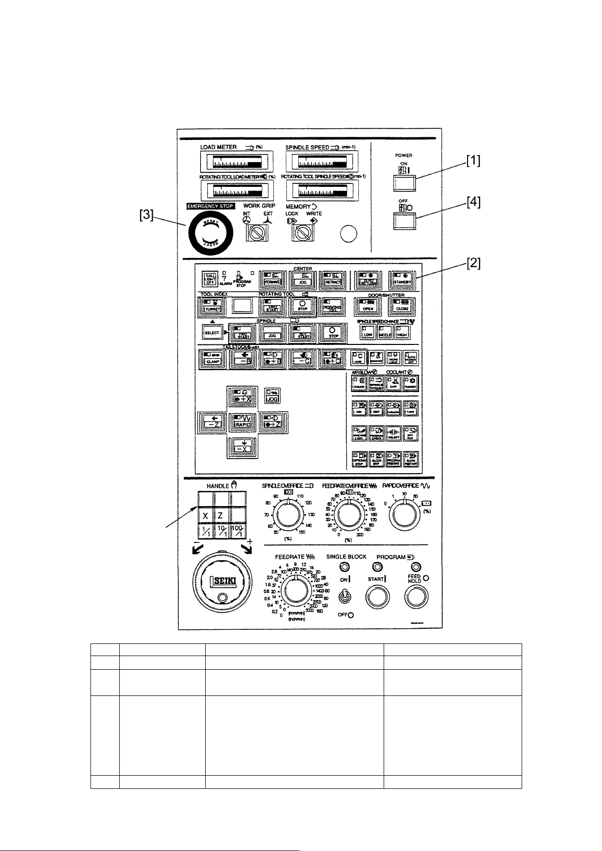
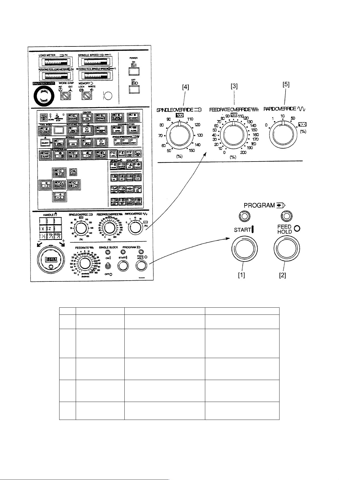
2 Explanation of Outline of Main and NC Operation Panel
2.1 Main Operation Panel
Statement in ( ) is
for option.
No. Name Function Remarks
[1] POWER ON The power of NC unit is ON. The power ON lamp lights.
[2] STANDBY Make the machine condition ready to The sheet key lamp lights.
operate.
[3] EMERGENCY Make the machine condition impossible to Emergency stop is displayed on
STOP BUTTON operate. the upper left of the screen.
(However, the hydraulic pump does not
stopped.)
Stop a section under operation.
(Clear or discontinue the contents.)
[4] POWER OFF The power of NC unit is OFF.
1 - 2
Page 11
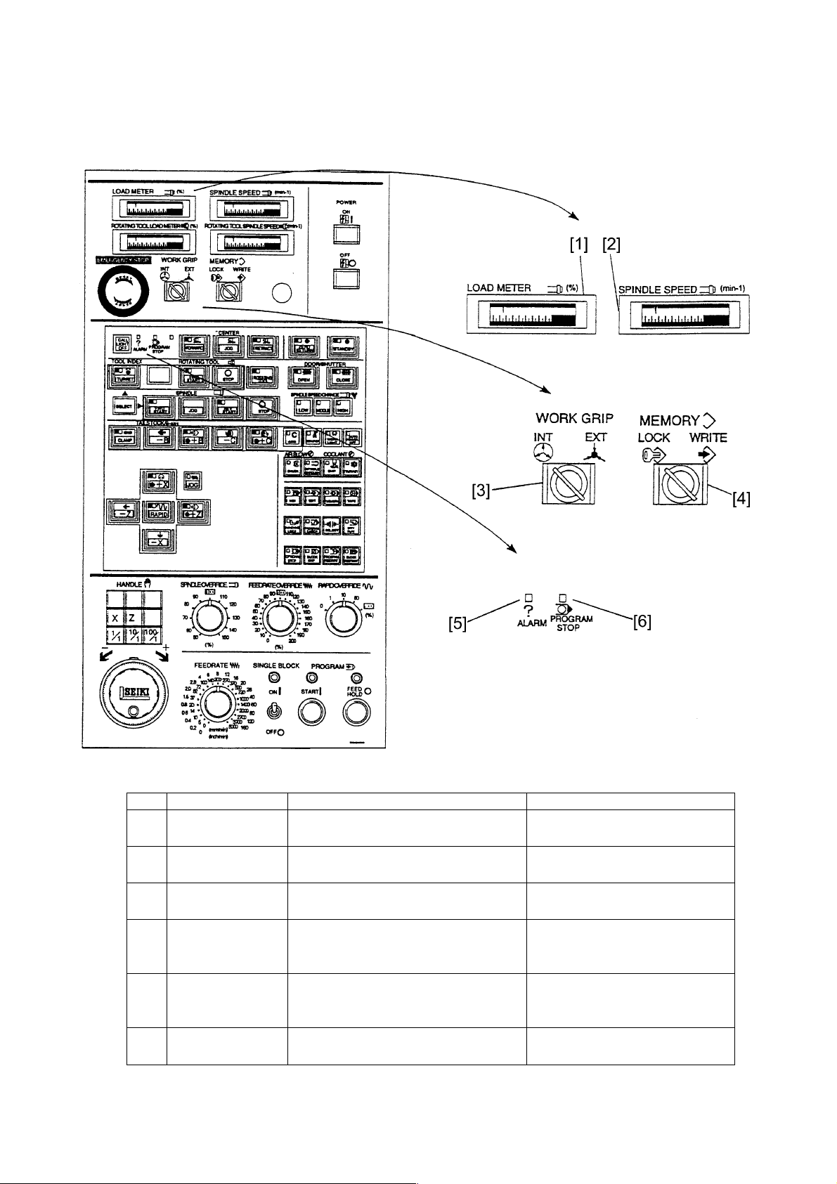
No. Name Function Remarks
[1] LOAD METEROF A load condition of the main motor is
SPINDLE displayed.
[2] Tachometer of To indicate RPM of spindle
Spindle
[3] WORK GRIP Select the clamping direction of the Pull out the key selection as a rule.
(INT, EXT) KEY spindle for a workpiece to be cut.
[4] MEMORY Select the effective or ineffective of Set to the lock and pullout the key
(LOCK, WRITE) editing operation of program and after edition.
KEY parametor.
[5] ALARM LAMP It is lit when occurring abnormality on the
NC alarm, motor, lubrication or machine
etc.
[6] PROGRAM STOP It is lit when executing the M00, M01 or
LAMP M30 by MDI or automatic operation.
1 - 3
Page 12
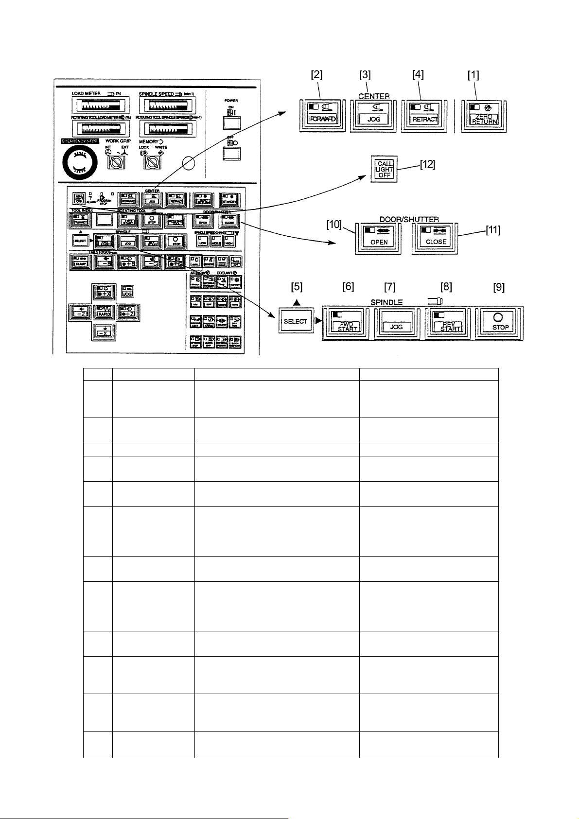
No. Name Function Remarks
[1] ZERO RETURN Return to the reference point in the order At the time of power on, each axis
KEY of X and Z axes. zero returns automatically after
moves minus side.
[2] CENTER Advance the tailstock continuously. Option
FORWARD KEY
[3] CENTER JOG KEY Advance the tailstock while pressing.
[4] CENTER Retract the tailstock while pressing.
RETRACT KEY
[5] SPINDLE SELECT Press this key simultaneously when
KEY forward or reverse the spindle.
[6] SPINDLE FWD The spindle rotates forward by pressing There are interlocks of the door
START KEY with the effective key simultaneously and chuck for the condition of
when manual mode. spindle rotation. The lamp is lit
when the spindle rotates forward.
[7] SPINDLE JOG ON The spindle rotates while pressing.
KEY
[8] SPINDLE REV The spindle rotates reverse by pressing There are interlocks of the door
START KEY with the effective key simultaneously and chuck for the condition of
when manual mode. spindle rotation. The lamp is lit
when the spindle rotates reverse.
[9] SPINDLE STOP The spindle stops when manual mode
KEY
[10] DOOR OPEN KEY Door open command by manual at the This lamp is lit when the door is
time of the auto door specification. opened. This specification is an
option.
[11] DOOR CLOSE Door close command by manual at the This lamp is lit when the door is
KEY time of the auto door specification. closed. This specification is an
option.
[12] CALL LIGHT OFF Turn off the call light. The call light lights when program
KEY stop or alarm condition.
1 - 4
Page 13
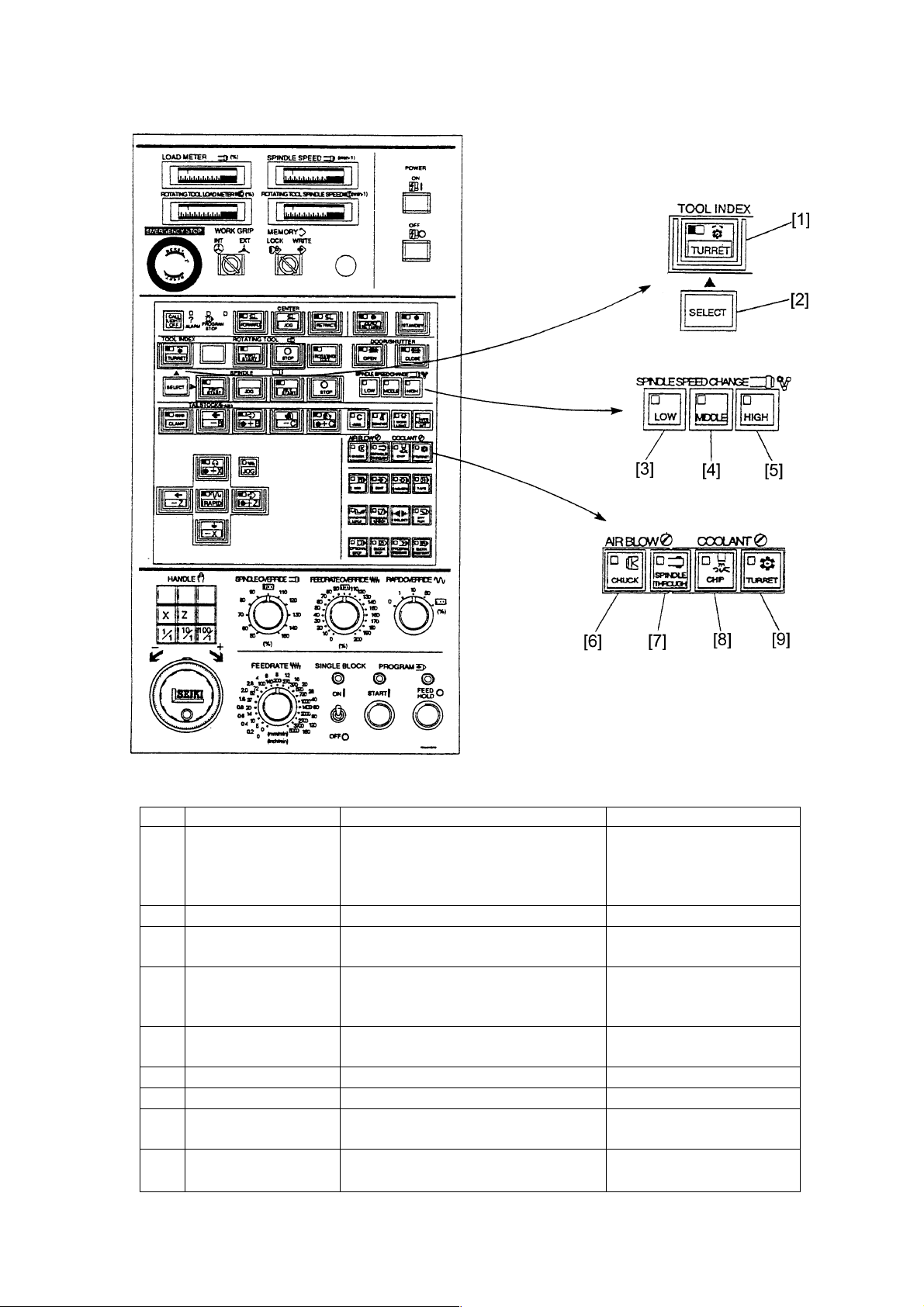
No. Name Function Remarks
[1] TOOL INDEX START In the manual mode:
KEY By pressing this key and the effective key
simultaneously, the tool rest starts
rotation.
[2] SELECT KEY
[3] SPINDLE SPEED
CHANGE LOW KEY
[4] SPINDLE SPEED Spindle middle speed side range.
CHANGE MIDDLE
KEY
[5] SPINDLE SPEED Spindle high speed side range.
CHANGE HIGH KEY
[6] AIR KEY (CHUCK) To direct air supply manually (Chuck)
[7] AIR KEY (IN SPINDLE) To direct air supply manually (In Spindle)
[8] COOLANT MANUAL To direct coolant supply manually (Chip
KEY sink)
[9] COOLANT MANUAL To direct coolant supply manually (Tool
KEY rest)
1 - 5
Page 14
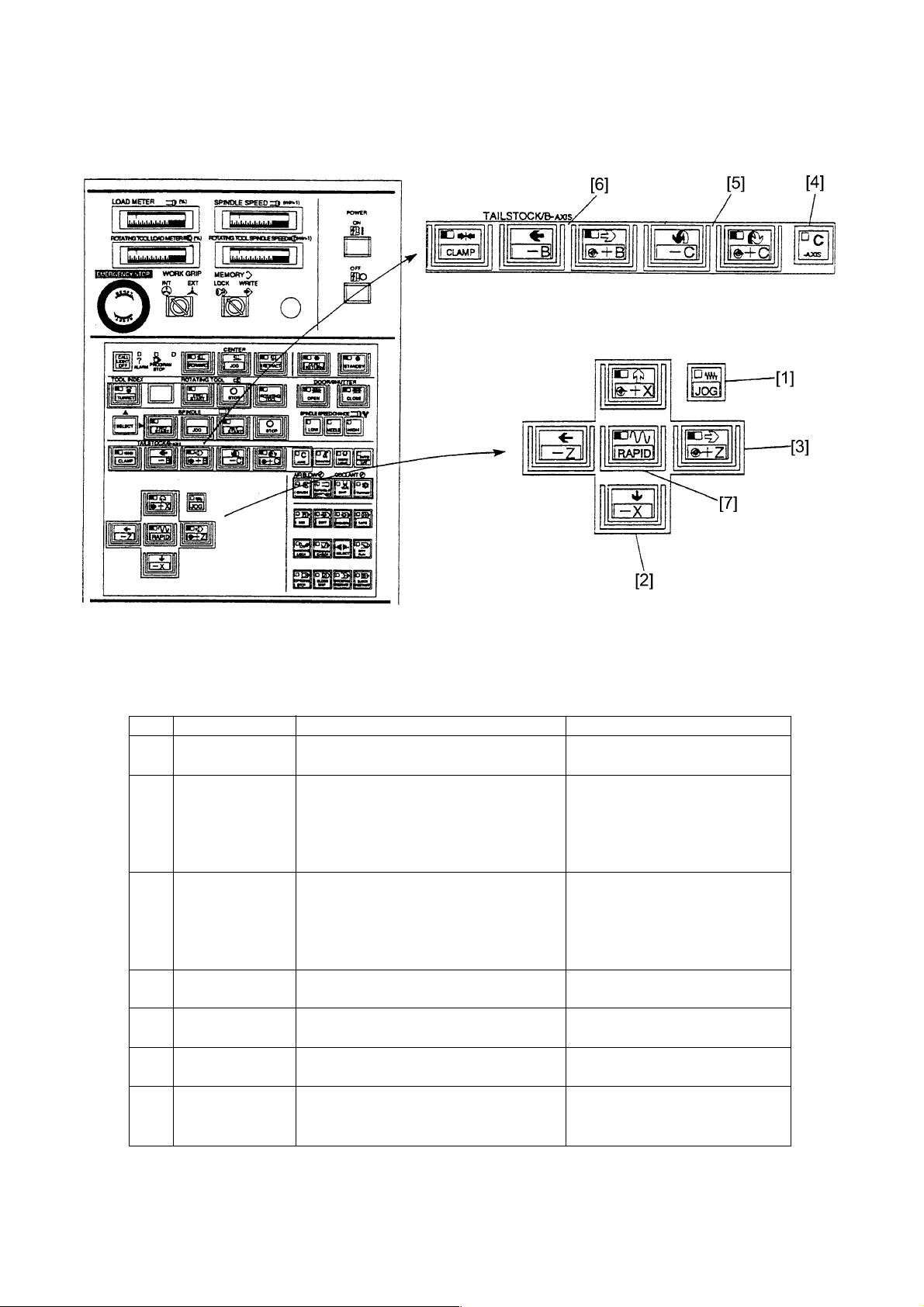
No. Name Function Remarks
[1] JOG KEY Select when executing the operation of Under manual mode.
the manual continuous feed.
[2] +X, -X KEY The manual continuous feed is available Set the feedrate by the feedrate
at the mode key is feed. switch.
Move continuous in the selected direction When the +X key is kept pressing,
by pressing any one of +X or -X key. it is stopped at the machine
reference point.
[3] +Z, -Z KEY The manual continuous feed is available Set the feedrate by the feedrate
at the mode key is feed. switch.
When the +Z key is kept pressing,
it is stopped at the machine
reference point.
[4] C+AXIS KEY Select this when execution of the C-axis
continuous feed.
[5] +C,-C KEY The manual continuous feed is available
at the mode key is feed.
[6] +B,-B KEY The manual continuous feed is available
at the mode key is food.
[7] RAPID KEY Move by the rapid traverse with setting %
value of override while pressing under the
manual continuous feed.
1 - 6
Page 15
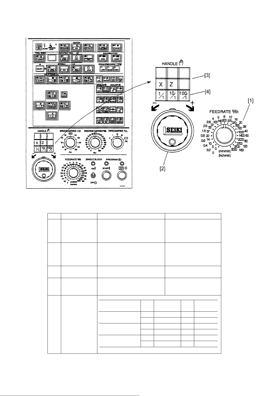
No. Name Function Remarks
[1] FEDERATE Select the feedrate when 0~5000mm/min
SWITCH execution of the manual 21 steps
continuous feed or program check
operation (dry run).
[2] HANDLE Execute the handle feed (a fine 100div./ rev.
feed of the machine), when one of A feed amount per division is
the X, Z, B or C axes under feed according to the setting of
mode. magnification [3].
[3] FEED AXIS KEY Select one of the X, Z, B or C Automatic mode
when moving by the handle.
[4] HANDLE FEED Select an amount per division of
MAGNIFICATION the handle.
CHANGE KEY
Feed magnification Axis Indication Axis Indication
key amount µ amount
1/1 X 1 B 1µ
Z 1 C 0.001°
10/1 X 10 B 10µ
Z 10 C 0.01°
100/1 X 100 B 100µ
Z 100 C 0.1°
1 - 7
Page 16
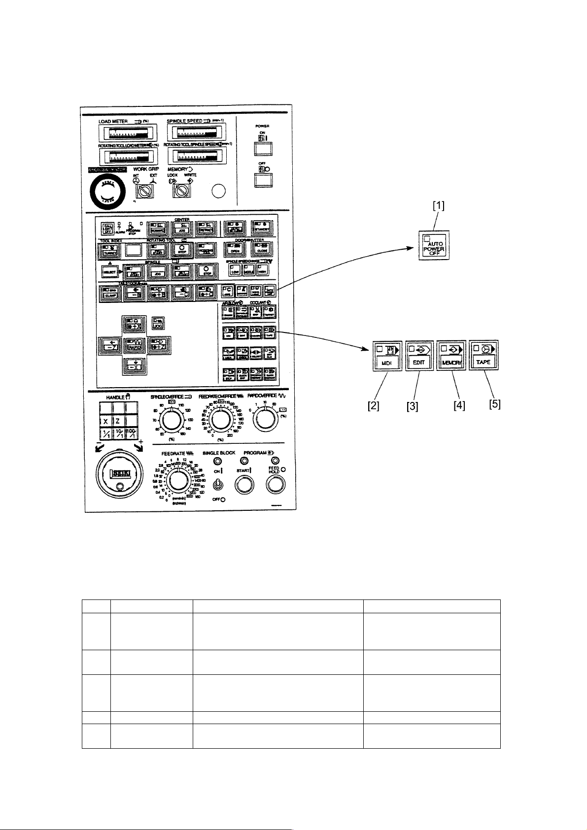
No. Name Function Remarks
[1] AUTO POWER Power is cut automatically, when request
OFF KEY of power cut off by an alarm or the robot
specification.
[2] MDI Select when MDI input by the CRC Automatic mode
operation panel of NC unit.
[3] EDIT Select when editing program stored. Automatic mode
Select when storing or punching out the
program tape.
[4] MEMORY Select when execution of program stored. Automatic mode
[5] TAPE Select when execution of operation by the Automatic mode
program tape.
1 - 8
Page 17
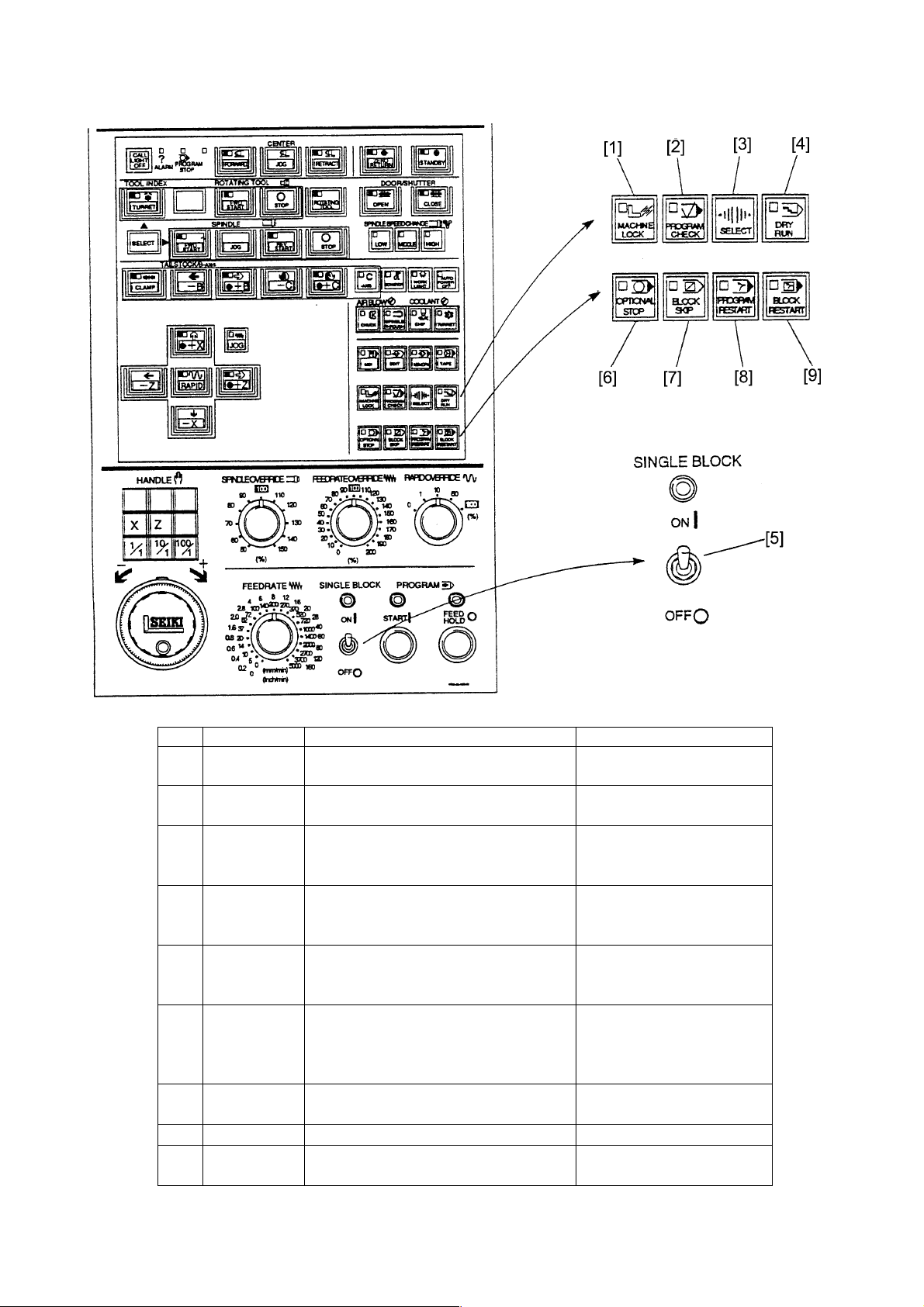
No. Name Function Remarks
[1] MACHINE Each axis is fixed at the current position
LOCK and does not move.
[2] PROGRAM Make the stop condition of spindle and
CHECK coolant besides the dry run function.
[3] SELECT KEY Press this simultaneously when selecting
one of the dry run, program check or
machine lock.
[4] DRY RUN Ignore the rapid traverse or cutting
federate of program and it moves by the
setting value of federate switch.
[5] SINGLE Stop after execution of one block and
BLOCK move to the execution of next block by the
start key.
[6] OPTIONAL Program stops by the M01 on the
STOP program.
Press the program start key when start
again.
[7] BLOCK SKIP Skip a block with slash (/) code in the
program.
[8] PROGRAM Restart the program.
[9] BLOCK Restart the BLOCK.
RESTART
1 - 9
Page 18
No. Name Function Remarks
[1] PROGRAM START Start automatic operation.
KEY (MDI, Memory, Tape)
[2] PROGRAM FEED Halts automatic operation. Dowel does not halt.
HOLD KEY Feeding only decelerates and MST function is kept on while
stops. the work continues, and halts
when completed.
[3] FEDERATE Feed rate can be changed in the
OVERRIDE range of 0 to 200% under MDI or
SWITCH automatic operation.
[4] SPINDLE The spindle speed can be Ignores while thread cutting
OVERRIDE changed in the range of 50 to (G32, G92, G76)
SWITCH 150%
[5] RAPID OVERRIDE The rapid speed can be changed
in the range of 0 to 100%
1 - 10
Page 19
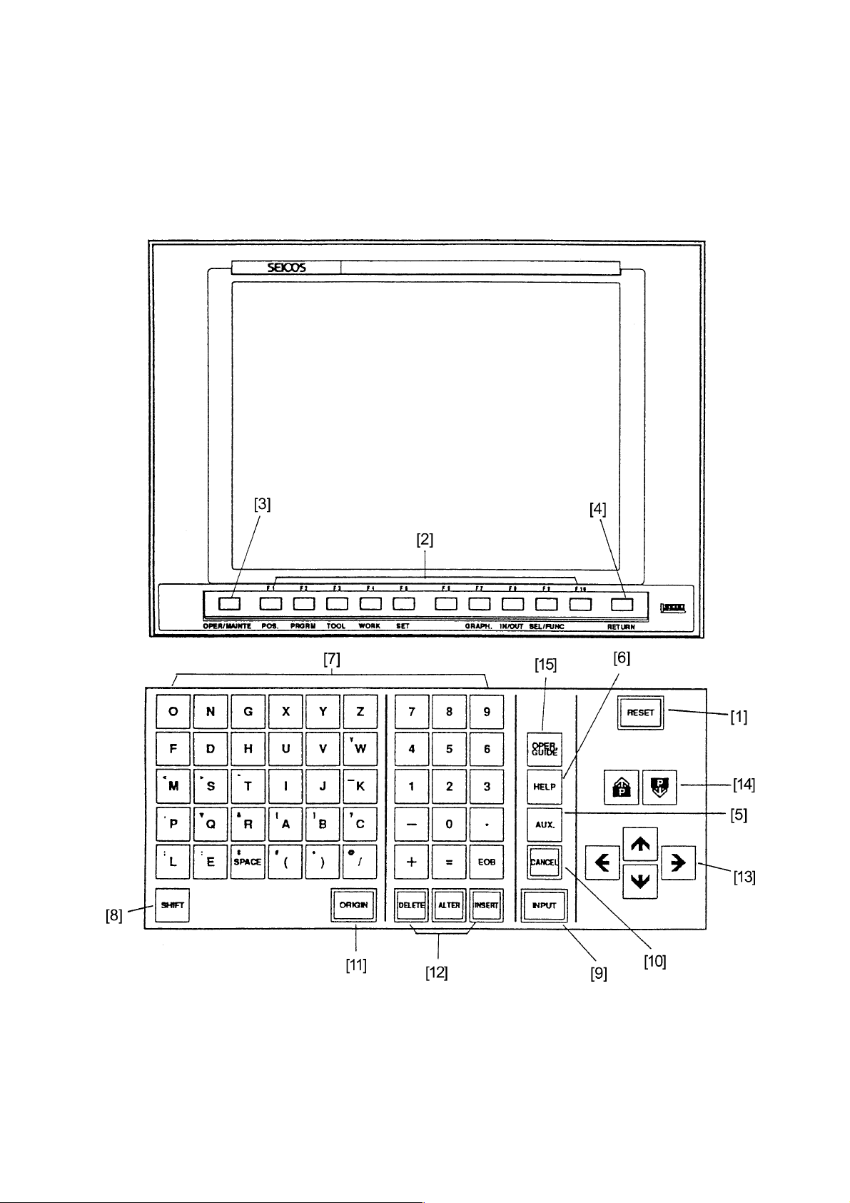
2.2 NC Operation Panel
1 - 11
Page 20

No. Name Use
[1] RESET KEY Press this when the CNC is wanted to reset, to release an alarm etc.
[2] FUNCTION KEY When function keys are displayed at the bottom of CRT, it becomes
the selection key of the menu.
When menu is not displayed, it becomes the selection key of screen
as the position, program, tool, work coordinate, setting, drawing or
in/output.
Press the selection/function key when the function menu is
displayed at the bottom of CRT.
[3] OPER/MAINTE KEY In case of the screen of PC, alarm or maintenance etc. is displayed,
press this key.
The function menu is displayed at the bottom of the bottom of CRT
when pressing the key once and disappears it by pressing again.
[4] RETURN KEY Press this key when the screen returns “General screen”.
[5] AUX KEY Use this to display the special screen (for maintenance)
[6] HELP KEY
[7] ADDRESS/ Use this key to input alphabets or numerals.
NUMERAL KEY
[8] SHIFT KEY Some of address key has two letters in one key. Upper left letter is
inputted when address key is pressed with shift key.
[9] INPUT KEY When the address or numeral key is pressed, input it in the buffer
storage once and displays on the CRT.
Press the input key when this data input inputted in the buffer
storage want to set actually .
[10] CANCEL KEY Press this when the letter or symbol inputted in the buffer storage.
[11] ORIGIN KEY Use this to clear the coordinate value or drawing screen etc.
[12] DELETE, ALTER, Use this to delete, alter or insert the editing operation of program.
INSERT KEY
[13] CURSOR KEY There are four cursor moving keys.
Use this to move the cursor up and down or left and right.
[14] PAGE KEY There are two page turn over keys.
Use this to turn over the page advance or reverse direction.
[15] OPERATION Use this key to get operation guide information on the screen
GUIDE display.
1 - 12
Page 21
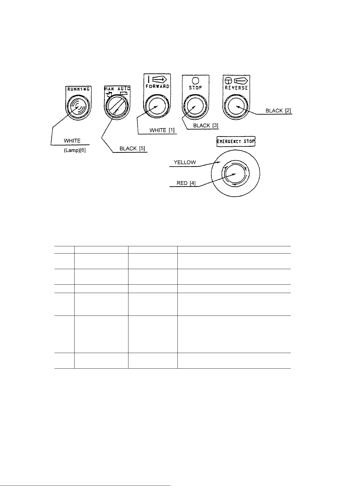
2.3 Chip Conveyor Operation Panel
1) Chip Conveyor Operation Panel
Chip Conveyor Operation
Panel Diagram
2) Function
No. Name Type Function
[1] Forward Push Button Forward switch is valid in manual mode only.
The action is kept on.
[2] Reverse Push Button Reverse switch is valid in manual mode only.
Inching operation.
[3] Stop Push Button Stop switch is valid regardless of the mode.
[4] Emergency Stop Mushroom Type Emergency stop switch is valid for stopping
both chip conveyor/main machine, regardless
of the mode.
[5] Man/Auto Switching In manual mode: Buttons [1] [2] are valid.
In auto mode: By command from the main
machine, forward operation is stopped.
Buttons [1] [2] are invalid. Do not switch
man/auto during operation.
[6] Running Lamp Lamp lights while the chip conveyor is is in
operation.
1 - 13
Page 22
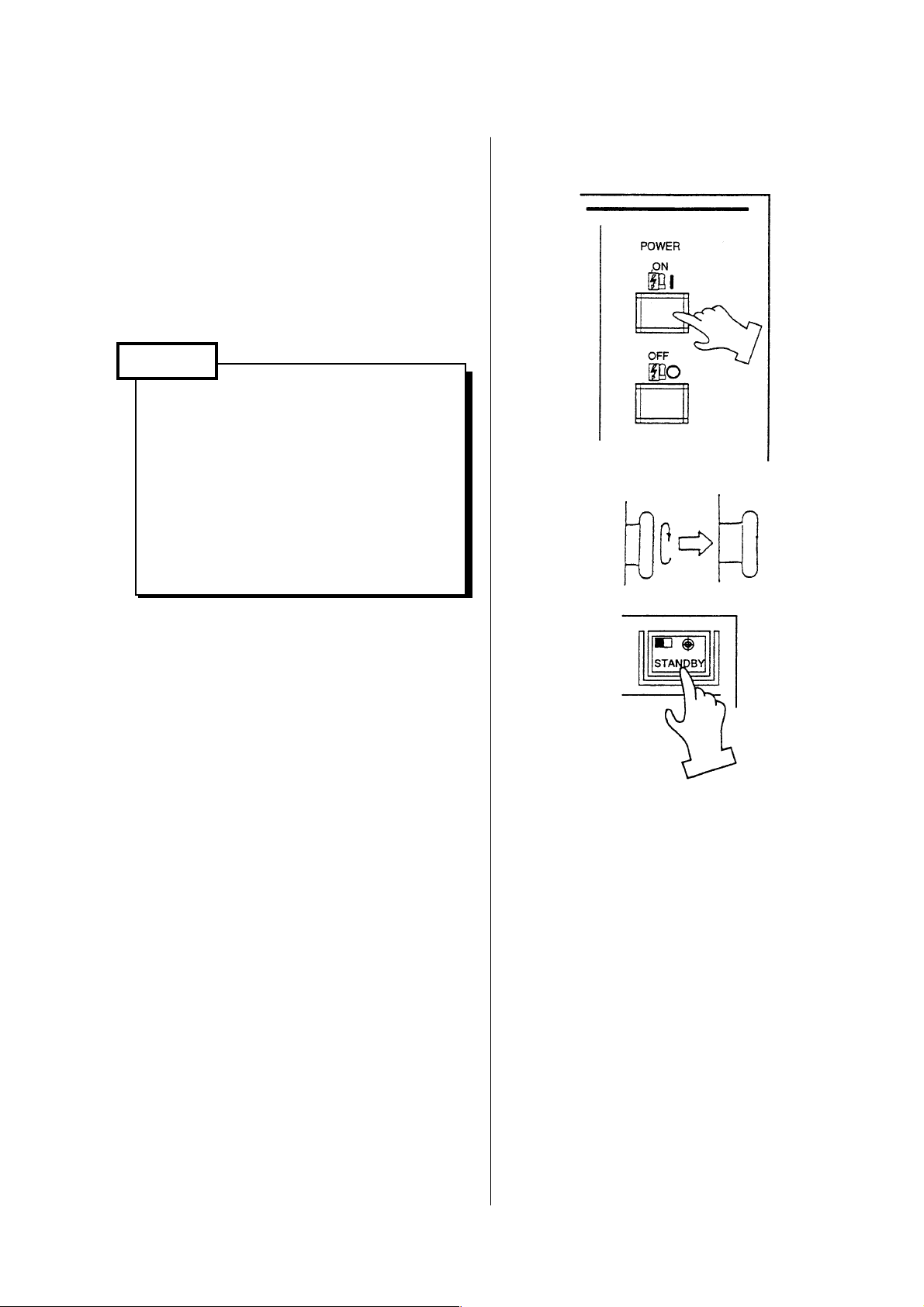
3 Procedure of Machine Operation
3.1 At the Time of Start
1) Turn on the power source switch.
2) Turn on the power switch of the power
control cabinet.
3) Press the push button for NC unit power
[ON] on the main control panel.
Caution
Main panel and NC unit is sealed
type construction and avoid a mixture
of outer air directly. Therefore, don’t
keep open the door long time of
period during power on.
Check a display of CRT and
running of cooling fan motor at in/
out side of box.
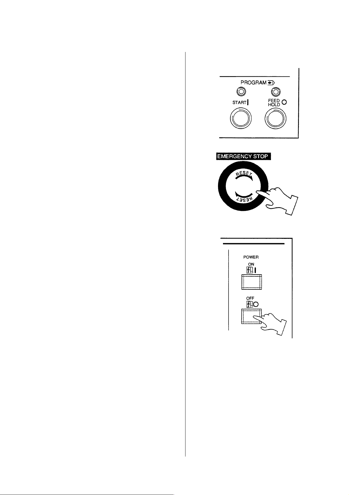
4) Turn right the emergency stop button.
5) Press the [STANDBY] button on the
right corner of the main operation panel.
(Green lamp lights.)
Check a setting pressure of hydraulic
2
unit is 3.5Mpa{35kgf/cm
6) Move X and Z axes several times to
lubricate each slide way before starting
operation.
(Pay attention to avoid over travel.)
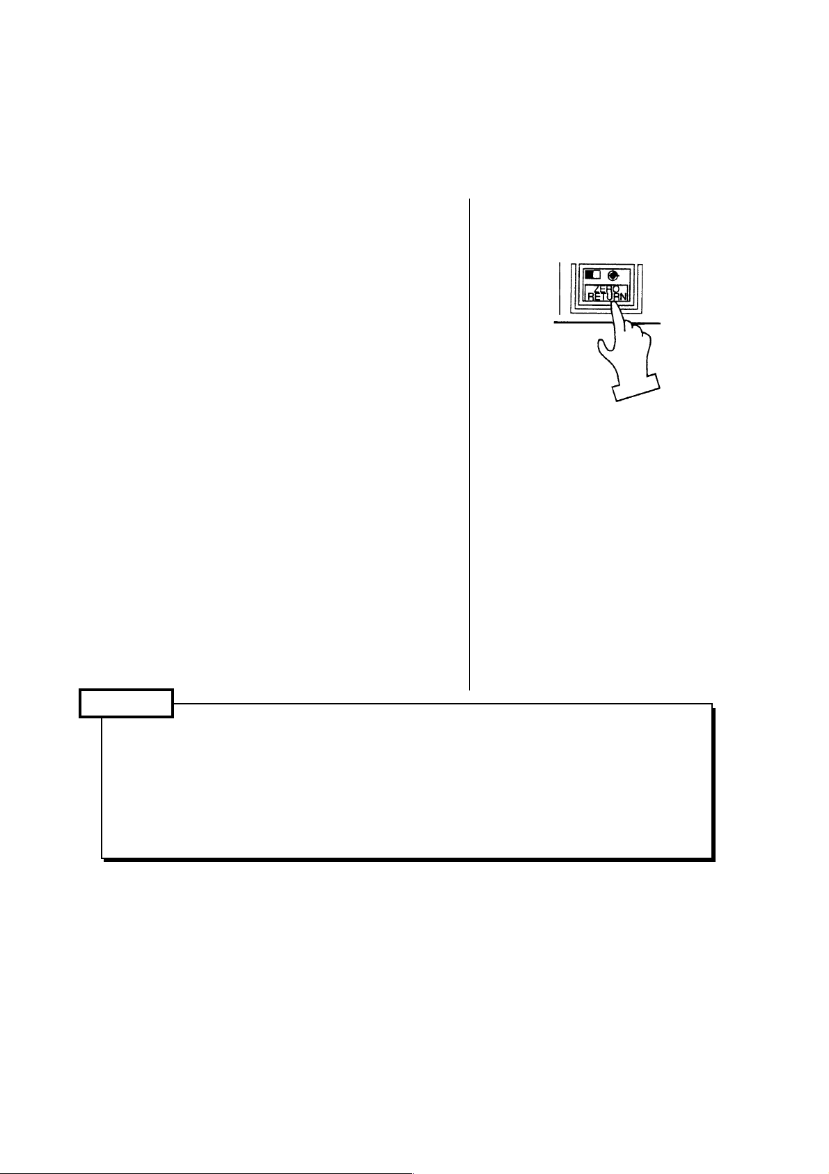
7) Press the [ZERO RETURN] key.
(Refer to “Procedure of zero return”)
Basic machine coordinate system is set
and stored stroke limit becomes
effective by executing of zero return.
8) Turn on the switch for chip conveyor.
}as fixed value.
1 - 14
Page 23

Caution
Do not operate the machine with
plenty of chip in the trough of chip
conveyor.
3.2 Warming-up Operation of Spindle
Caution
It is important to keep status of bearing in good condition by lubrication, etc., to make
the spindle rotate normally. Sudden rotation of the spindle may cause sticking of the
bearings because of shortage of lubricating oil at the bearing section. To get the best
performance of the spindle function by correct operation, warming-up operation as
below-mentioned is necessary.
Warming-up operation for every starting (30 minutes)
[1] 10 minutes at 30% of the maximum spindle rotation
[2] 10 minutes at 50% of the maximum spindle rotation
[3] 10 minutes at 80% of the maximum spindle rotation
Conduct warming-up operation in the above order, [1], [2], [3]
1 - 15
Page 24
3.3 Procedure of Zero Return
Manual zero return must be done after
power turned on, to initiate the basic
machine coordinate system.
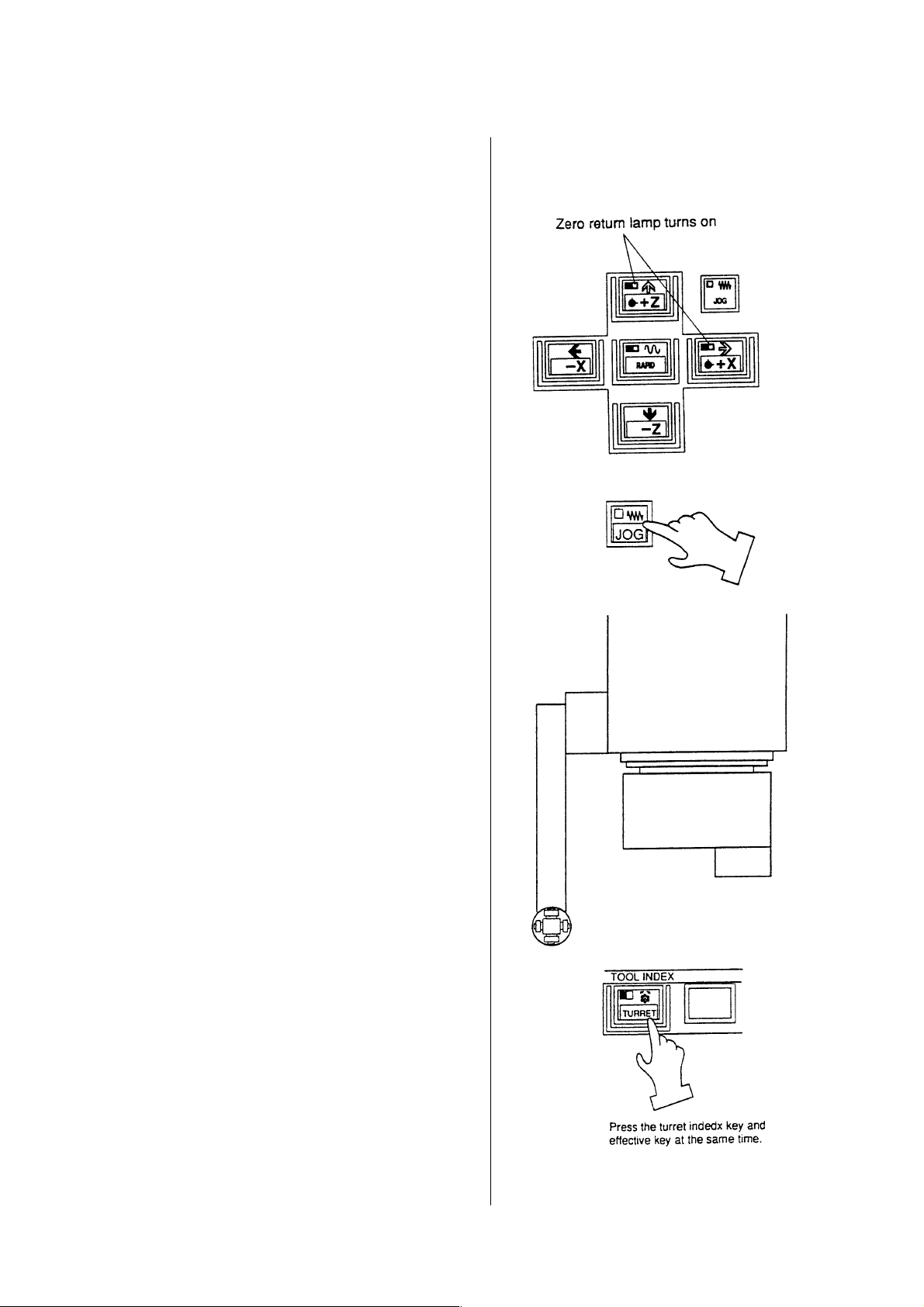
Method 1 of zero return
1) Make a mode push button switch to
“Feed”.
2) Press the [ZERO RETURN] key.
3) Move a tool head to zero point by rapid
traverse (25% override). The tool head
stops at zero point and a confirmation
lamp of zero point of the axis turns on.
Method 2 of zero return
1) Make a mode to “Feed”.
2) If the X and Z axes locate near the zero
point, move it opposite direction (Minus)
from zero point about 100mm.
3) Press in the order of “X +” and “Z +”
and the lamps of zero point turn on.
4) Release a finger from the switch after
the lamp turned on.
Execute zero point return of each axis by
the operations above.
Caution
1. Execute zero return of axis one by one for safety.
(At first, do it from X-axis.)
2. Pay attention of interference with the tailstock at the time of zero return.
3. 100% of rapid traverse override is effective after zero return is performed.
1 - 16
Page 25
3.4 At the End of Operation
1) Clean up the machine.
Stop the chip conveyor after all chips
carried out from the conveyor.
2) Confirm the machine stopped
completely.
• Spindle rotation
• Program
• X and Z axes
• Coolant
• Chip conveyor
3) Press the [EMERGENCY STOP] button
on the main operation panel.
4) Press power [OFF] button at the main
operation panel and control power off.
5) Turn off the power switch of the power
control cabinet.
6) Set the main power switch [OFF].
1 - 17
Page 26
4 Manual Operation
4.1 Feed of Each Axis
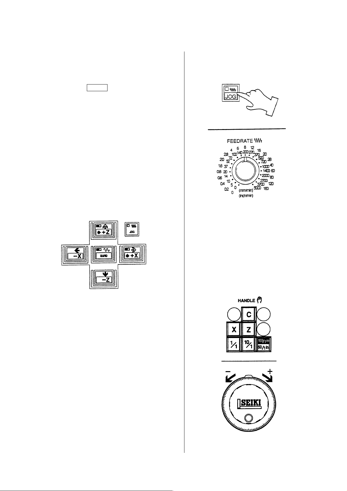
— In case of manual feed —
1)
Press the FEED for mode select push
button switch.
You may select the “Handle” either.
2) Set the manual federate rotary switch to
suitable speed.
Move the machine to desired direction
by the manual feed direction push
button switch.
Take a finger off from the switch when
reach to the fixed position.
(The machine moves only when
pressing the switch.)
In case of a feed by the handle, it can
be operated the same about it.
(Example of use)
• Warm up running
• In case of approach near the zero position.
• In case of cutting manually
• Setting work
1 - 18
Page 27

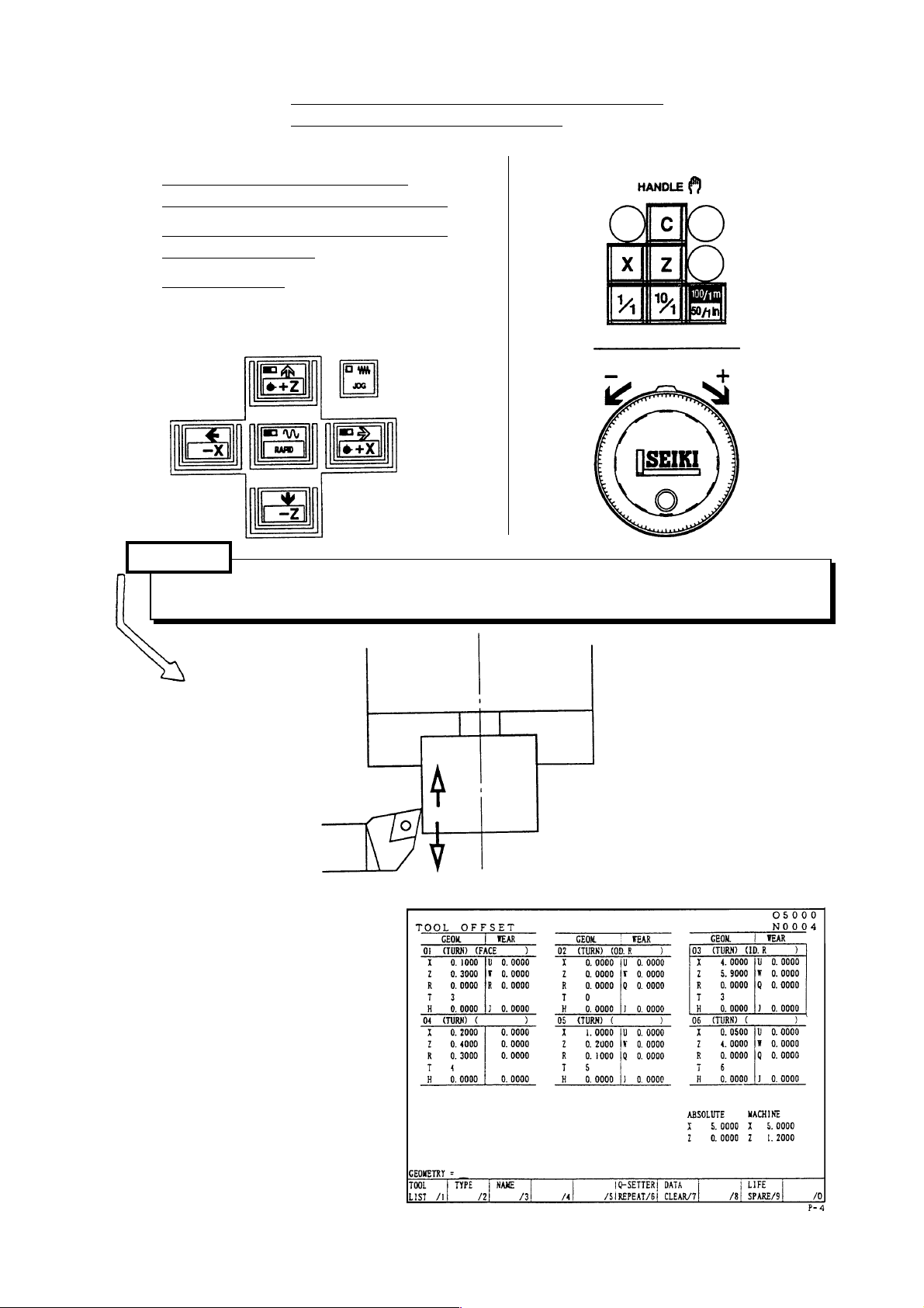
— In case of the handle feed —
1) Select the axis by the axis push button
switch.
2) Fine feed can be done by the manual
handle.
• When select 1/1: One division is
0.001mm
• When select 10/1: One division is
0.01mm
• When select 100/1: One division is
0.1mm
In case of the spindle indexing C axis,
the unit becomes a degree.
1 - 19
Page 28
4.2 Operating Method of Q-setter
A tool position compensating value can be
get easily, since a tool position
compensation is inputted automatically by
touching a tool tip to the Q-setter.
In case of the turret rotates, a cursor
changes automatically due to a tool face
number correspond an offset number.
1) Confirm the zero return condition of the
X and Z axes.
If confirmation lamp is not lit, execute
manual zero return.
2) Make a mode to manual mode (Handle
or feed).
3) Pull out the Q setter
A screen changes to the offset screen
automatically and display the “Q-setter”
and inform a ready of complete
condition of preparation.
4) Call a tool compensation required.
Make a mode to “Feed”.
1 - 20
Page 29
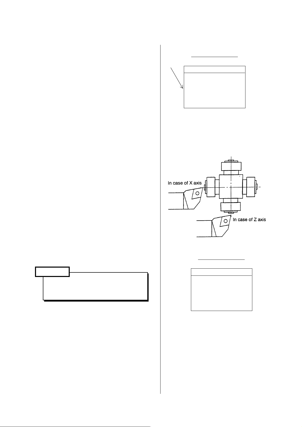
5) Confirm a tool face on the turret and
offset number.
A tool face selected at this moment is
recognized by a cursor position.
Note) Set a wear compensating amount
zero, if it is not zero.
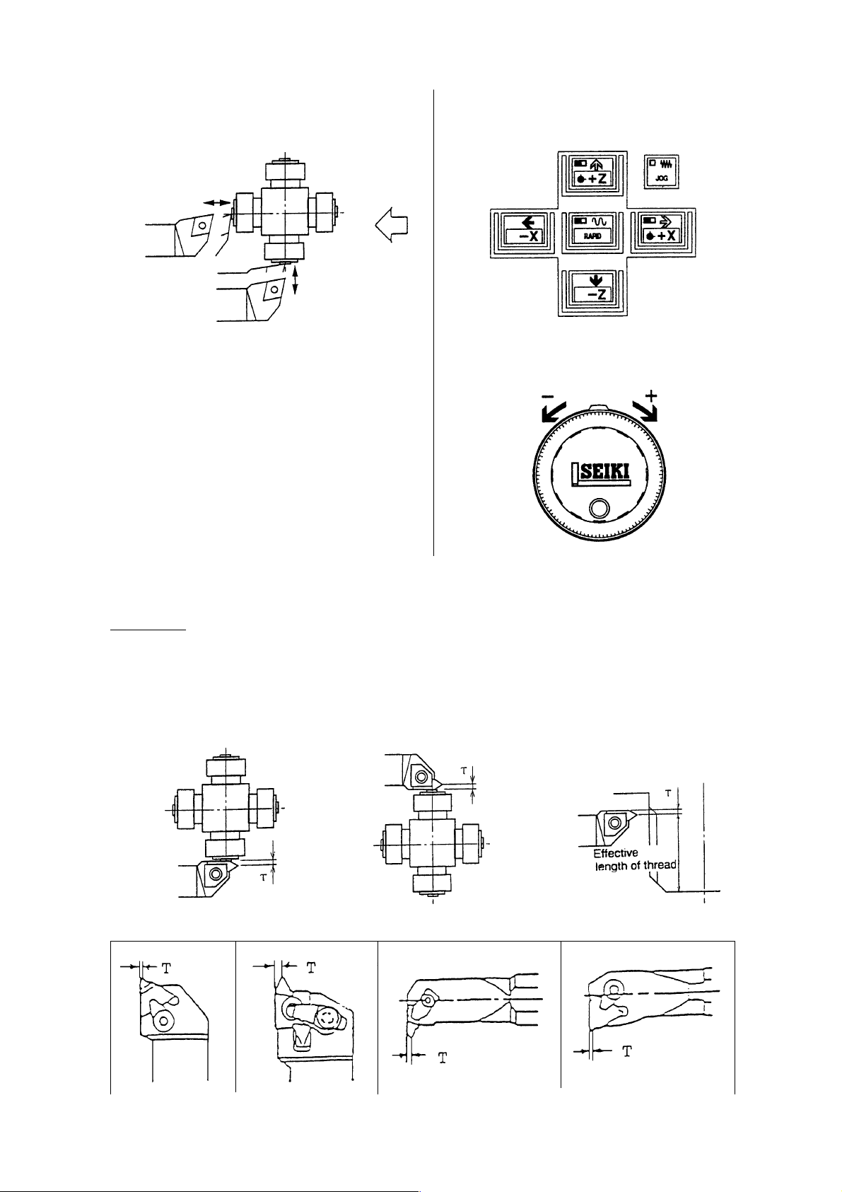
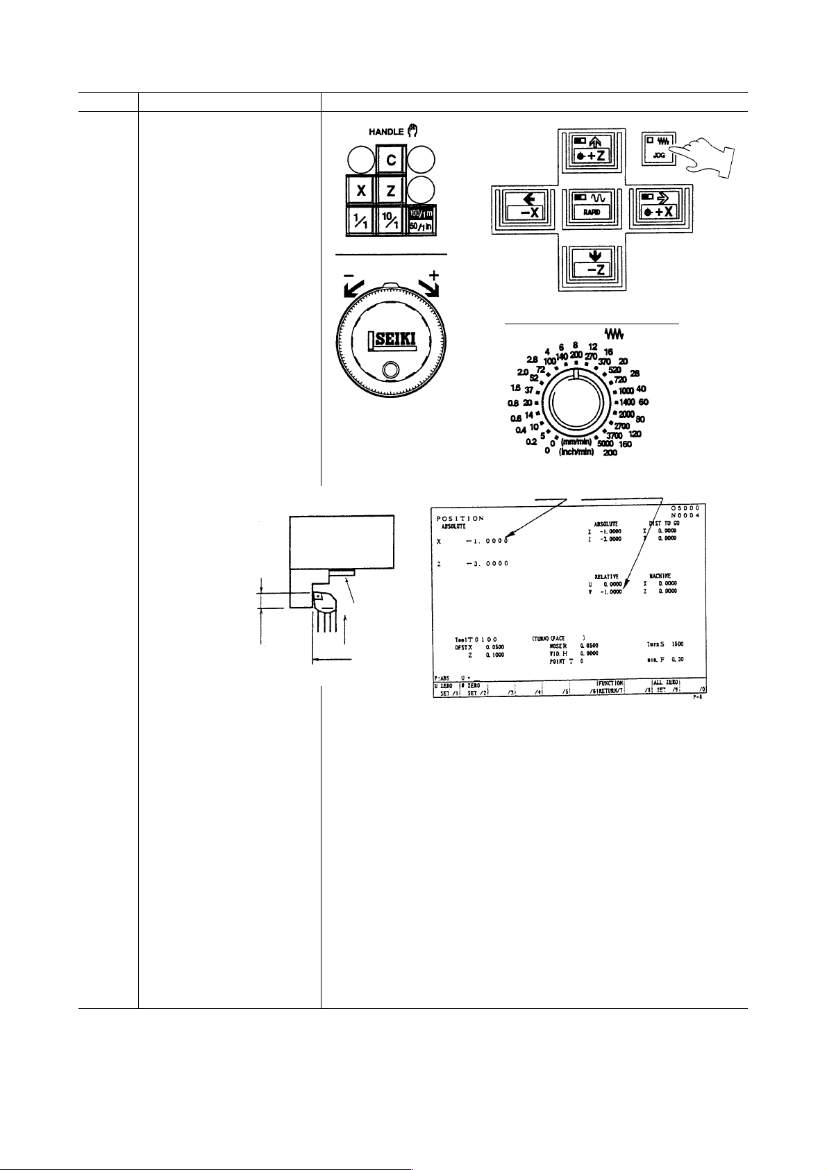
6) Approach a tool tip to the tool setter
(Q setter)
Procedure (1) Handle magnification key
100/1
Cursor
Tool (Compensation)
Sharp Wears
01
X 1.000 U 0.000
Z 3.000 W 0.000
R 0.000 Q 0.000
T3
H 0.000 J 0.000
(2) Rotate a handle to minus
direction.
7) Position a tool tip to the center of the
sensor by handle feed.
8) When a tool tip touches the sensor by
feed mode, a compensating value is
inputted automatically.
Caution
Do not operate at 100/1. It is
dangerous as the move amount is
too big.
When a tool tip touch to the sensor,
sound beep and stop the tool head and
input a compensation value.
Tool (Compensation)
Sharp Wears
01
X 35.000 U 0.000
Z 0.125 W 0.000
R 0.000 Q 0.000
T3
H 0.000 J 0.000
1 - 21
Page 30
9) Execute a tool tip measurement by
touching a tool tip to the sensor twice or
so.
Confirm a tool compensation
amount on the screen.
10) Retract a tool tip from the sensor to
safety zone by handle feed. A safety
zone is a position which is not interfered
a tool and sensor even if the turret
rotates.
11) Get a compensation amount for the
other tool in turn as the same method.
OTHERS
Reference In case of thread cutting tool
In case of thread cutting tool, a tool compensation value of Z value is obtained by the side
of insert as described by Fig. 1 and 2, effective length of thread becomes short by “Width
T” due to position of cutting edge is different. Therefore, get a tool compensation amount
by the Q setter as Fig. 1 then execute incremental compensation input to minus side (In
case of Fig. 2, plus side), so correct effective length of thread can be get as Fig. 3.
Fig.1(Right hand thread) Fig.2(Left hand thread) Fig.3
1 - 22
Page 31

How to get a tool compensating amount for a tool
tip may not be touch the Q-setter
A work coordinate system setting should be
done before executing this operation.
A correct compensating amount can not be
found without a work shift operation.
“How to get a tool compensating amount
Ι.
for a longitudinal direction (Z)”
1. Call a tool by index the turret.
Select the mode
switch either the
handle or feed.
Press the turret index key and
effective key at the same time.
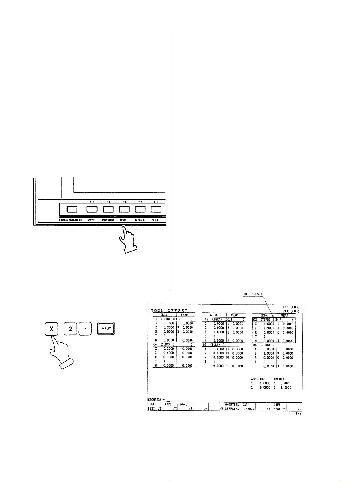
2. Call the tool offset screen and
confirm a tool compensating amount
is zero.
Set zero if it is not zero.
Press the function key F3/TOOL .
Example: In case of T0200
Set the tool (offset) No. 02.
1 - 23
Page 32
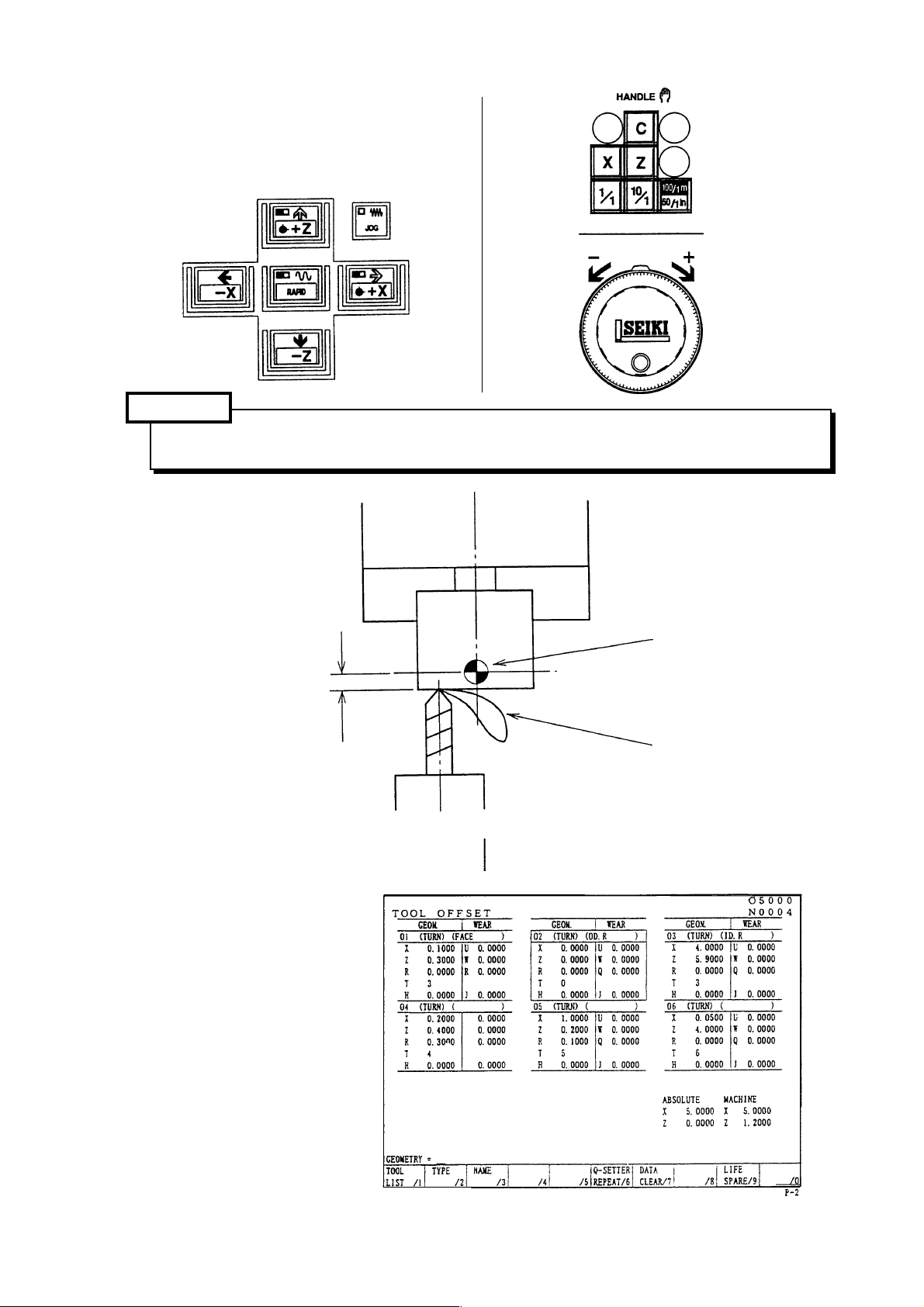
3. Touch a tool to the end face of
workpiece.
It the end face is a black skin,
execute it after cutting a black skin.
Caution
Reduce a magnification of the handle to avoid a breakage of tool and apply a paper
between a workpiece and tool.
3.0
Removal amount L
4. watch a position “Z” of tool position.
Machining reference point
Paper
1 - 24
Page 33
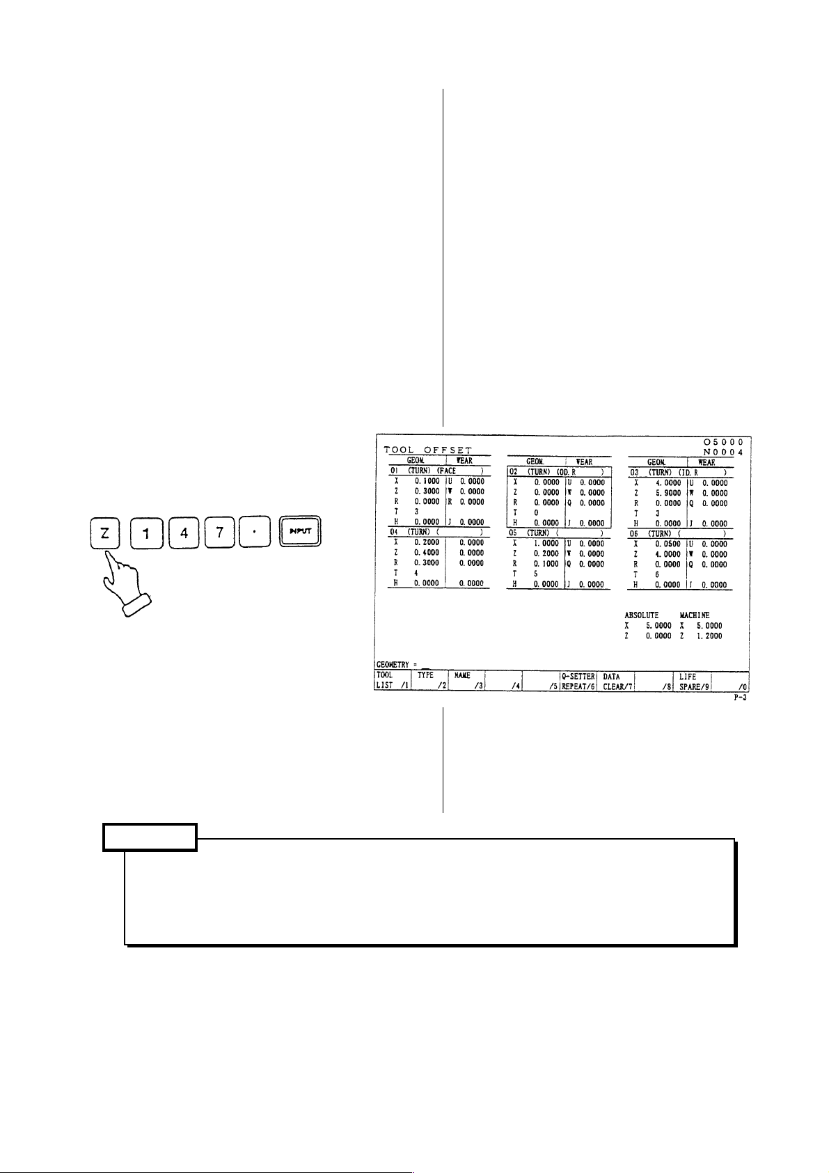
¡ Tool compensating amount
A value subtract a removal amount (l)
from a tool position (Z).
Toll compensating amount (Z) = [Tool
position (Z) - Removal amount (
Example: Tool compensating amount
= (150.0) - (3.0) = 147.0
147.0 is a tool compensating
amount of the longitudinal
direction.
5. Input a tool compensating amount.
) ]
Caution
Execute it with confirmation, if the setting of shift amount (machining original position)
of Z-axis work coordinate system is correct or not before this
Besides, a tool tip position should be same as a removal amount when a tool touches
end face is has touched the Q-setter.
1 - 25
Page 34
How to get a tool compensating amount for a tool
tip may not be touched the Q-setter.
“How to get a tool compensating
II.
amount for a radial direction (Z-axis) ”
It is the same as longitudinal direction
from the item 1 to 3.
Refer it to them.
1. Cut a workpiece.
Caution
To avoid a defective parts, it is enough a skin cut. Never move on the X-axis after OD
turning.
2. Watch a position “X” of tool position.
Example: In case of T0300
Set the tool (offset) No.03.
1 - 26
Page 35
¡ Tool compensating amount
A value subtract a diameter of workpiece
(φD) from a tool position (X).
Toll compensating amount (X) = [Tool
position (X) - machined diameter of
workpiece (φD) ]
Example:T ool compensating amount
= (65.0) - (63.0) = 2.0
2.0 is a tool compensating amount of
the diameter direction.
3. Input a tool compensating amount.
1 - 27
Page 36
4.3 Q-setter Repeat Function
A tool compensation amount is once measured by Q-setter, the measurement for the
replaced tool tip can be repeated in a simplified operation.
4.3.1 Procedures
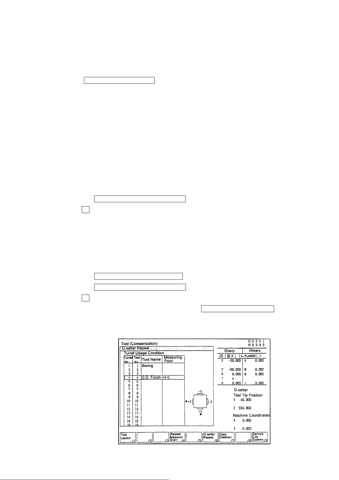
1) Press F6/Q-SETTER REPEAT on the tool (compensation) screen and get the
window screen of the “Q-setter Repeat”.
2) Put the mode into “Manual”.
3) Replace the tool tip and index the turret to the measuring position.
Then, the cursor position in the turret usage condition on the left of the screen and
compensation data on the upper right of the screen change connecting with the turret
face.
Confirm the virtual tool tip position.
4) Get the Q-setter arm.
5) Make positioning of the tip to be measured in an arbitrary position where there is no
risk of touching the sensor.
6) Put the mode into “Feed”.
7)
Press the F4/REPEAT MEASURE START key.
Input Y , answering the “Query Y-Yes or N-No”.
If it is the tool for which previously measured by Q-setter (when there is measured
data on the screen), the “Q-setter Repeat” measuring action will start and the
measured data is written in as compensation amount when the tool touches the
sensor.
Also, a touch mark “
If the tool has previously not been measured by Q-setter, an alarm is issued.
Press the F5/REPEAT MEASURE STOP key to stop the action.
Press the F4/REPEAT MEASURE START key again to restart the action.
Input Y , answering the “Query Y-Yes or N-No”.
8)
When the measurement is completed, press the F6/FUNCTION RETURN key to
return the “Tool Compensation” screen.
9) Store the Q-setter.
•” is shown on the illustration of measurement point on the screen.
1 - 28
Page 37
4.3.2 Movement
The movement of the virtual tool tip point is divided into 9 patterns, as shown in Fig.3.
When virtual tip points 1, 2, 3, 4 are designated, measurement is made both on the X and
Z axes. The measurement should always be made in the order of Z axis to X axis.
When virtual tip points 0, 5, 6, 7, 8, 9 are designated, measurement is made on either
one of the X or Z axis only. In this case, it is necessary to previously input a
compensation amount manually for the axis which is not measured.
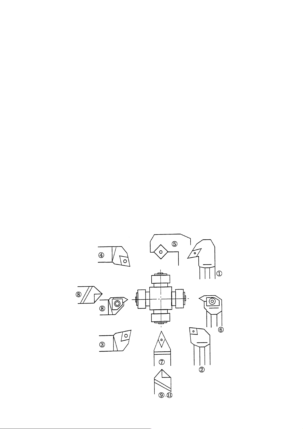
As for the virtual tip point of the tool, see Fig.1.
As an example, the case of virtual tip point 1 is explained in the following. (See Fig.2)
1) Shift from the start point (P0) to the point 1 (P1) by rapid feed.
2) Shift from P1 to P2 by rapid feed.
3) Shift from P2 to P3 by rapid feed.
4) Move from P3 to the final touch point (P4) by jog speed.
5) Move from the point of touch and stop to P5 by jog speed.
6) Shift from P5 to P6 by rapid feed.
7) Shift from P6 to P7 by rapid feed.
8) Move from P7 to the final touch point (P8) by jog speed.
9) Move from the point of touch and stop to P9 by jog speed.
10) Shift from P9 to P10 by rapid feed.
11) Shift from P10 to the start point (P11) by rapid feed.
Fig.1 Virtual tip point of tool
1 - 29
Page 38
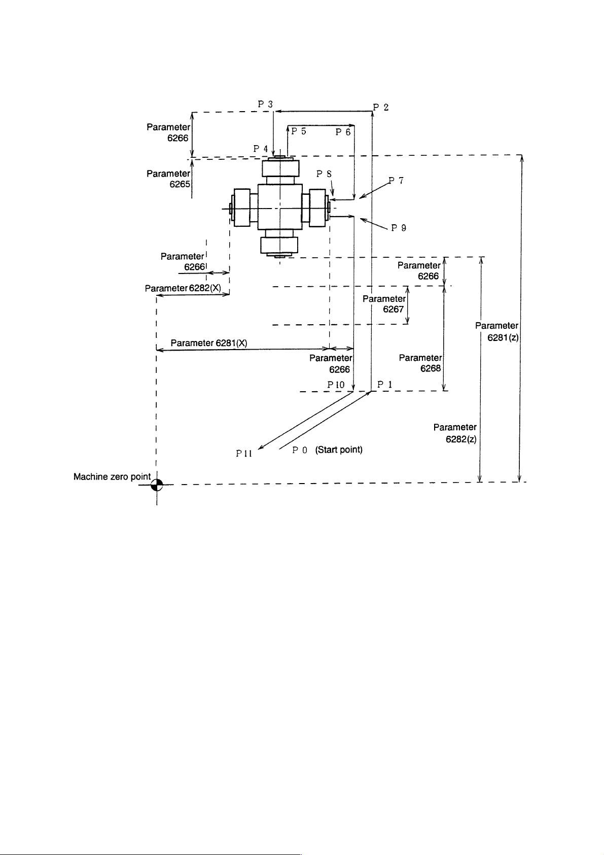
Fig.2 Movement in the case of virtual tip point 1
1 - 30
Page 39
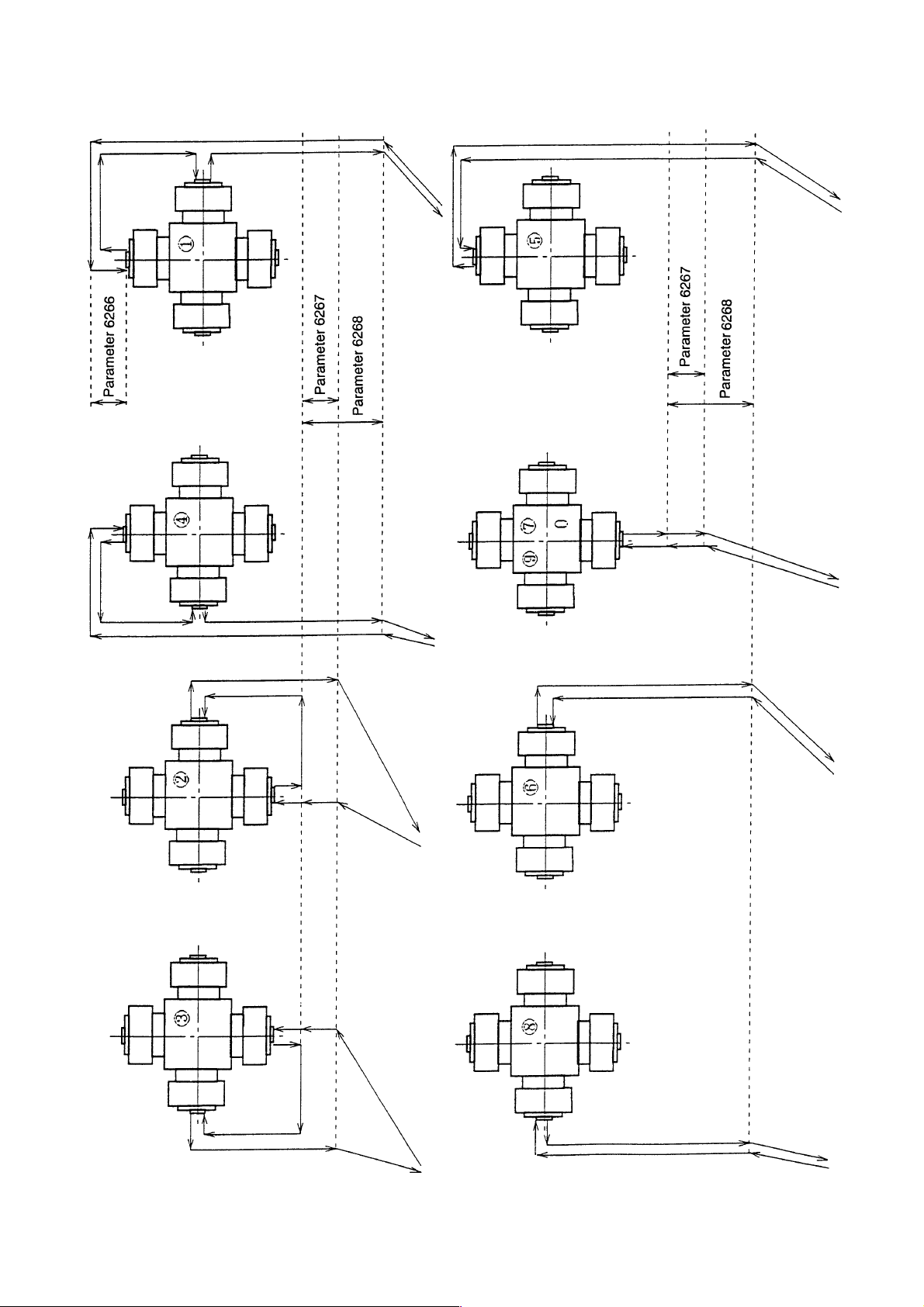
Fig.3 Movement pattern
1 - 31
Page 40

Caution
1) Whenever a tool is changed, make sure to apply Q-setter in the manual mode.
2) The action of applying Q-setter is one time only.
3) For measurement action, single block is effective. (Restarted by pressing the
F4/REPEAT MEASURE START key)
4) If machine-locked in the Q-setter mode, an alarm is issued.
5) In the Q-setter mode, when the selection of compensation No. is changed by moving
the cursor position of by page key, the measurement is made on that compensation
No.
6) When there is a danger of the start point interfering with the sensor, an alarm is
issued.
7) If the tip does no touch the sensor during the measurement movement, an alarm is
issued after completion of the action.
8) Measurement is not available for thread cutting tool, tip-change type drill bit, end mill
and tools similar to these.
9) Depending on the movement pattern, when there is an interference between the tool
and workpiece, detach the workpiece from the chuck.
10) When there is a difference of 0.5 or more between Q-setter measurement
andworkpiece measurement, adjust the Q-setter position on the maintenance screen.
11) The Q-setter repeat function is available only when the tool No. to be measured is
inputted on the “Tool No.” column of the tool list. Usually, the turret No. and the tool
No. should coincide, the screen display of which is not to be changed.
4.3.3 Relevant Alarm
No.715 Machine lock was acted during measurement.
No.724 Q-setter measurement has never been performed.
No.738 Touch signal of Q-setter repeat is abnormal.
No.739 Measurement start point of Q-setter is not proper.
Move the tool tip away from Q-setter slightly.
1 - 32
Page 41

4.4 How to Shape Soft Jaw
In order to manufacture precision products of high commercial value, without flaws on
workpiece, a soft jaw is formed. By forming a soft jaw matching with the chuck, cutting work
can be performed safely and steadily thus the accuracy of processed goods will improve.
For shaping a soft jaw, there are two methods; one is to utilize the simple soft jaw forming
function, the other is to form one by manual operation.
4.4.1 Shaping by utilizing Simple Soft Jaw Forming Function
On the soft jaw forming screen, input necessary data of “Jaw form” and “Cutting
conditions” according to the guiding message appears on the screen. By pressing the
start button, the forming of a soft jaw is processed automatically.
(1) Operation
1) The part where a ring (core metal) is to be attached is processed and a ring is
attached.
2) The tool used for a soft jaw forming is indexed at the cutting position.
3) On the screen of work coordinates system (General
F4/WORK COORDINATES ), press the F6/SOFT JAW FORM key to get the
window screen for soft jaw forming.
4) Select either outside jaw forming or inside jaw forming by pressing the corresponding
key F4/OUTSIDE JAW FORM or F5/INSIDE JAW FORM .
5) Input the data on the jaw shape and cutting conditions.
For details, see paragraph (3) of this section.
6) Rotate the spindle in the manual mode and move the tool to the position of the end
face of the jaw. Then press the F3/JAW END FACE SETTING key, and answering
to a message “Jaw End Face Position Setting? Y-Yes or N-No”, input “Y” to effect the
setting.
7) Press the F9/LOCUS CHECK key in the MDI mode and check the locus of the
cutting program. When not in the MDI mode, a message is displayed with a request
“Change the mode into MDI”.
During locus check, dry run and machine lock become effective, although the lamp in
the operation panel does not light on.
Also, MST code is not outputted.
Preset the coordinate system (tool tip position), when locus check is completed, also
at time of midway resetting.
By turning “Single Block” ON, and pressing the PROGRAM [START] button, the locus
can be displayed per each block.
To recheck the movement of the locus, press the F9/LOCUS CHECK key.
8) Move the tool away from the jaw end face in Z direction by about 5mm, and make
positioning of the starting point of jaw cutting. For this positioning, the X axis position
is arbitrary, but it is safer to set it within the range of the actual cutting diameter.
(When moving the tool, take care not to have the tool interfered with other machine
parts.)
9) In the MDI mode, press the start button and execute the soft jaw cutting program.
Press the SOFT JAW FORMING COMPLETE key, when the soft jaw forming is
10)
completed.
Answering the query whether terminating the process, input Y to complete the soft
→
1 - 33
Page 42

jaw shaping work.
(2) Function Key
F1/Magnified Drawing: Display of magnified jaw cutting portion is available.
F2/Arranging Work: Window screen for arranging work appears, thereby
allowing to make command on the spindle rotation
speed.
F3/Jaw End Face Setting: Message “Jaw End Face Setting? Y-Yes N-No” is
displayed.
Input F3 for setting.
F4/Outside Jaw Forming: For selecting outside jaw forming diagram.
F5/Inside Jaw Forming: For selecting inside jaw forming diagram.
F6/Function Return: Screen returns to Work Coordinate System display.
F7/Data Deletion: Message “Jaw Shape/Cutting Conditions Delete? Y-Yes
N-No” is displayed. Input F7 for clearing data.
F8/Soft Jaw Forming Complete: For completing soft jaw forming. This function key is
pressed when returning to normal work. Jaw end face
setting position is cleared.
F9/Locus Check: The locus of cutting program is drawn.
1 - 34
Page 43

(3) Jaw Shape and cutting Conditions
The meaning of each symbol of the jaw shape is as follows:
A: I.D./O.D of the first step
B: Depth of the first step
C: Diameter of the ring (core metal) used
D: I.D./O.D of the second step (If value 0 is set, the shape of jaw formed is a single step
jaw.)
E: Depth of the second step (If value 0 is set, the shape of jaw formed is a single step
jaw.)
T: Taper amount of the gripping portion
F: Necking depth
G: The maximum amount of cutting margin (If value 0 is set, cutting proceeds to Z
direction in rough cutting (See Note 1). If value larger than 0 is set, copy cutting is
performed in rough cutting (See Note 1))
Ι: Setting of necking width (relieving width)
J: Bolt position 1
K: Input the amount of the jaw protruding from the chuck diameter with +/- sign.
(based on the chuck diameter)
Cutting speed, Revolution: The condition relevant to spindle revolution. Input appropriate
values either in cutting speed or revolution.
Feed speed: The feed speed for rough an finish cutting.
Cut-in amount: Cut-in amount in the rough cutting.
The cut-in amount in the X axis direction, when rough-cutting is
performed in the Z direction.
The cut-in amounts in the X and Z axis directions, when performing copy
cutting.
If value 0 is set, will perform finish cutting only.
Finish margin: If value 0 is set, will perform rough cutting only.
Chuck O.D.
Soft jaw I.D. The dimension data necessary for jaw locus drawing.
Soft jaw O.D. These data have no direct connection with the machine action.
(Note 1)
}
Z direction cutting Copy cutting
1 - 35
Page 44

Caution
1) Before starting soft jaw forming, make jaw end face position setting. A warning is
issued, If locus check or soft jaw forming is executing without making the end face
position setting.
2) Clamp the maximum spindle revolution during the soft jaw forming with the parameter
setting value (No.5156).
3) Attention should be paid to the tool tip shape, when executing copy cutting and
necking processing.
4) The maximum value of the margin (G) is the value where the margin is considered to
be uniform both directions of diameter and lengthwise. When the margin in two
directions are different, the larger value should be taken as the maximum value of the
margin for the setting.
5) Use decimal point, for inputting the value of dimensions.
6) When attaching a jaw, make sure that the jaw does not protrude beyond the outside
diameter of the chuck.
7) For jaws, always use the standard soft jaw.
8) When processing a thin workpiece, chucking pressure may be lowered for avoiding
deformation of the workpiece, In such cases, take care not to set the spindle revolution
speed too high.
Refer to right figure finished shape.
Reference surface
0.5
Reference surface
20 or more
0.05
Cut with taper of abt.
30
The comer must be chamfered.
1 - 36
Page 45

(4)Relevant Alarms
The contents of the soft jaw forming error No.270 are as follows.
For example, the following message is given on the screen display.
[270] (#001) Soft Jaw Forming Error
↑
The detail of the alarm can be known by the numeral subsequent to # mark, the meaning
of which is as per list below.
#001 A≦0 (1st step O.D./I.D. is smaller than zero)
#002 B≦0 (1st step depth is smaller than zero)
#003 C≦0 (Ring diameter is smaller than zero)
#004 D≦0 (2nd step O.D./I.D. is smaller than zero)
#005 E≦0 (2nd step depth is smaller than zero)
#006 T <0 (Taper amount is minus value)
#007 F <0 (Necking depth is minus value)
#008 G <0 (Maximum margin is minus value)
#009 H <0 (Chamfering amount is minus value)
#00A I<0 (Necking width is minus value)
#010 C≧A (Ring diameter is bigger than 1st step I.D. in the outside jaw forming)
#011 C≦A (1st step O.D. is bigger than ring diameter in the inside jaw forming)
#012 D≧A (2nd step I.D. is bigger than 1st step I.D. in the outside jaw forming)
#013 D≦A (1st step I.D. is bigger than 2nd step I.D. in the inside jaw forming)
#014 C≧D (Ring diameter is bigger than 2nd step I.D. in the outside jaw forming)
#015 C≦D (2nd step I.D. is bigger than ring diameter in the inside jaw forming)
#016 B≧E (1st step depth is bigger than 2nd step depth)
#017 Chamfering is excessive.
#018 Necking width is too large.
#019 Interferes with bolt
#020 Cutting speed (roughing)≦0
#021 Cutting speed (finishing)≦0
#022 Feed speed (roughing) ≦0
#023 Feed speed (finishing) ≦0
#024 Cut-in amount ≦0
#OFF Soft jaw forming screen diagram not on display
No.729 Jaw end face position setting is not completed (Warning)
1 - 37
Page 46

4.4.2. Soft jaw forming by manual operation
Steps Operation method Movement Display
1 As shown figures in the
right, insert a ring (core
metal) on the front side of
a jaw. Adjust chuck
pressure to the same
value of the actual
operation.
Chuck
Soft jaw
Not to be protruded beyond
outside diameter of chuck
2 Obtain tool compensation
amount of the tool used for
soft jaw forming.
(Refer Q-setter operation
method)
3 Move the too l rest, and
apply the soft jaw forming
tool to the soft jaw .
Have the spindle rotate in
advance.
Portion to be
removed
Ring
This setting enables boring operation for accurate inside diameter
by watching the screen display of “position”, without using a
measuring instrument.
Soft jaw
1 - 38
Chuck
Ring
Page 47

Steps Operation method Movement Display
4 Set “W” of relative
coordinates at 0.
(1) Press the key
F1/POSITION
Then, screen
displays as shown in
the right column.
(2) Press
F7/ZERO-SET
(3) Press
F2/W ZERO-SET
Then, the value of W
becomes 0.
1 - 39
Page 48
Steps Operation method Movement Display
Scrape the jaw by
“Handle” operation, or in
the “Feed” mode.
• For this process:
Recommend separate
stages of course and
finish processings, as it
improves accuracy of the
cutting.
• Accuracy improves by
cutting the portion
FEEDRATE
chucking the ring beforehand.
• When soft jaw is reattached, make adjust
cutting for maintaining
chucking accuracy .
Cutting position and Display
Chuck
Current depth
of Claw
Diameter
Ring
Direction of
cutting
Diameter
Current jaws depth
1 - 40
Page 49
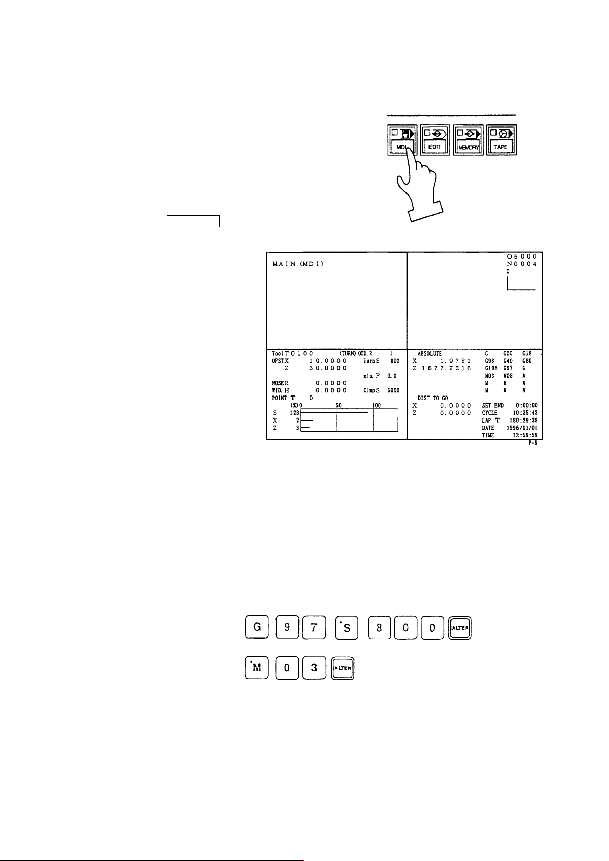
5 Operation by Manual Data Input (MDI)
5.1 Program input by MDI
A MDI program can be executed by the
following operation.
1. Select [MDI] on the operation panel
of the machine.
Press the RETURN key.
2.
3. Key in a MDI program by the address
and the data key.
Example: When the spindle rotates
-1
800 min
.
1 - 41
Page 50
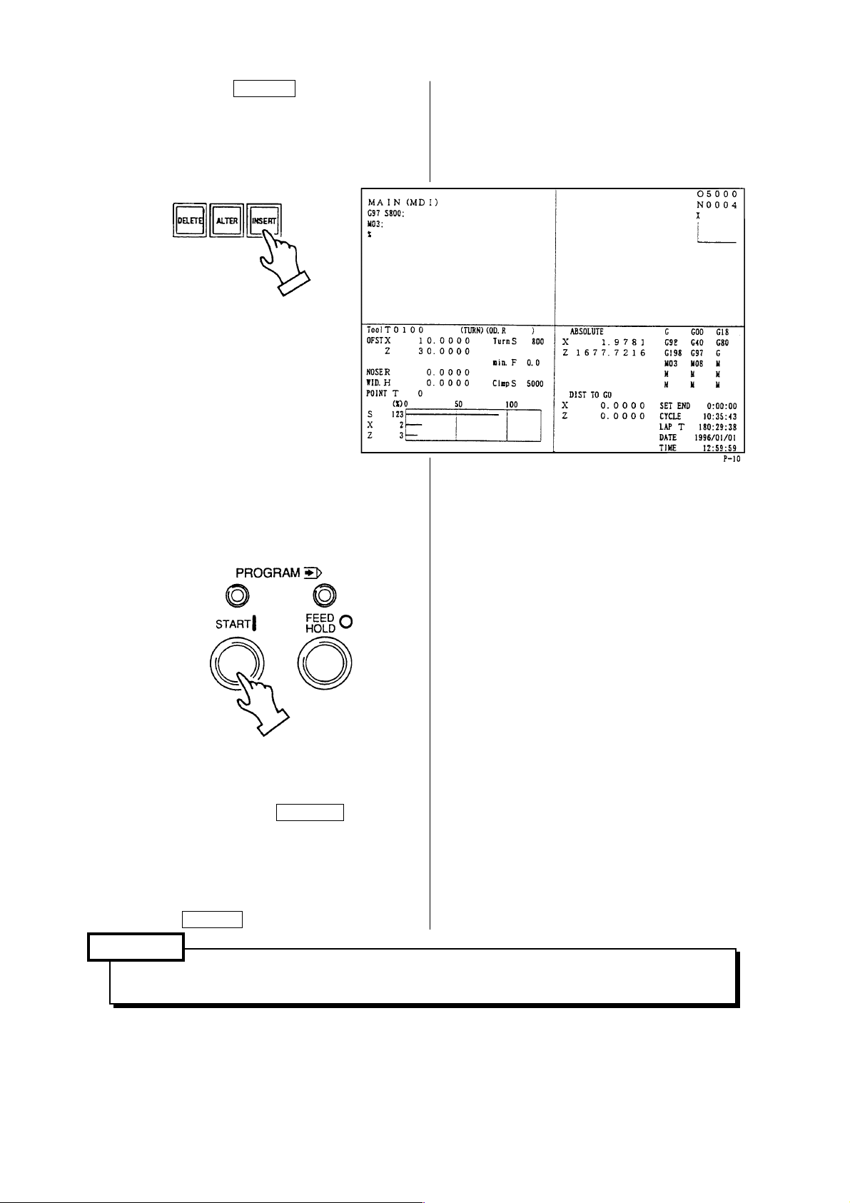
4. When the INSERT key is pressed, a
commanded value moves upper
section of the screen.
5. A command executes when pressing
the PROGRAM [START] key.
※1 If wrong key are inputted by
mistake, key in again after
pressing the CANCEL key
required number.
※2 When a mistake is found on an
inputted command, release a
command by pressing the
RESET key.
Caution
Pay full attention to the safety, since the machine moves.
1 - 42
Page 51
5.2 Edition of MDI program
An inputted MDI program can be edited
the same as a part program stored in
the memory.
1. The cursor moves back or forth at a
MDI program by a block unit when
the up and down CURSOR key is
pressed.
2. The cursor moves back or forth by a
word unit when the left and right
CURSOR key is pressed.
3. A MDI program moves back or forth
by a page unit when the PAGE key
is pressed.
4. Insert a data after the current position
of cursor by the INSERT key.
5. Alter a word, the cursor located
currently, to the inputted one by the
ALTER key.
6. A word, the cursor located currently,
deletes by the DELETE key.
7. A MDI buffer is cleared by the
RESET key. Key in the command
value again.
Caution
1. Editing is not available while
executing a MDI program,
however, it is possible when a
condition of the single block stop.
Execute the cycle start as it is,
after editing is finished.
2. In this case, please note that
regardless of the cursor position,
the program starts running from
the beginning.
1 - 43
Page 52

5.3 Operation of MDI program
1. Keep a mode of operation panel of
the machine a MDI, execute an
inputted MDI program by pressing
the
[START] button.
Caution
Put the cursor at the head of the
program, because it executes from
the current position of the cursor.
2. When a MDI program executes
sequentially, the cursor moves at the
head of the block currently executing.
3. The MDI program is deleted after an
operation of MDI program is
completed.
1 - 44
Page 53
6 Registration of Program
There are following two methods to register a program into the NC unit.
1. Registration from an external input device
2. Manual registration by the address/numeral keys
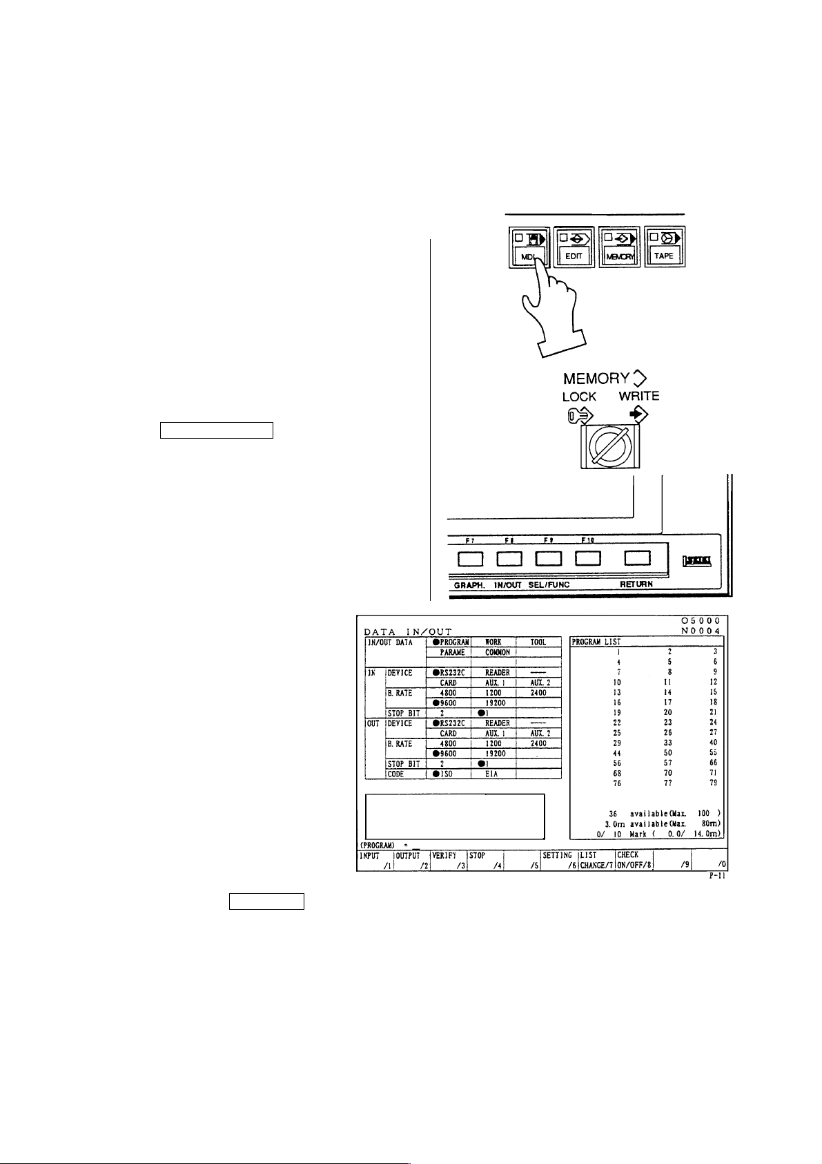
6.1 Registration from an external device
1) Connect an input device RS-232-C
terminal and make a possible
condition of transmission.
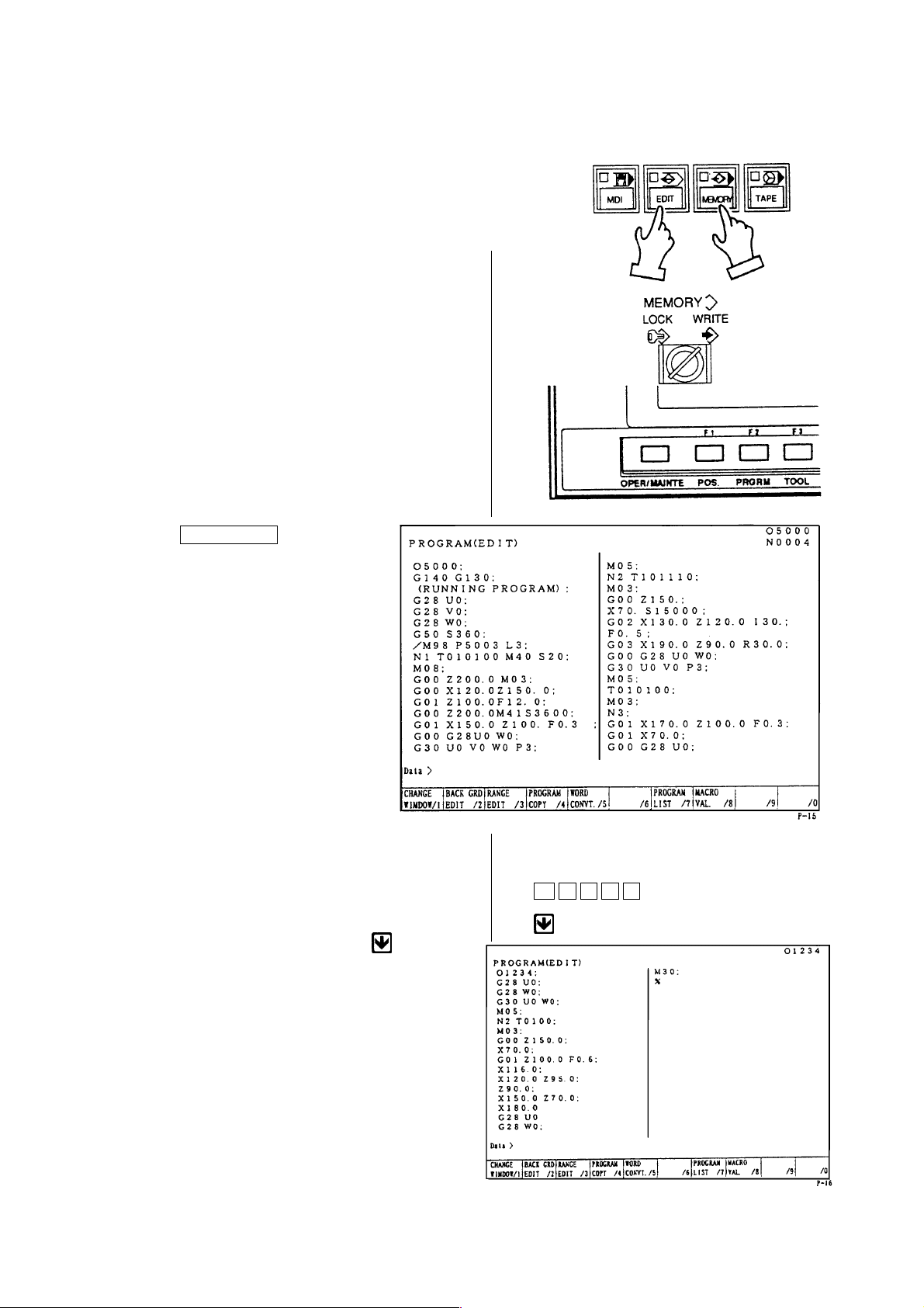
2) Set a mode to [EDIT].
3) Set the memory key to [WRITE].
4) Press the function key
F8/IN-OUTPUT .
Aright sketch is displayed.
5)
Press the F1/INPUT key.
• Start reading from the first EOB of the NC program and continue until the % code.
• The program No. is registered the 0 No. registered in the input device.
• Display at the program No. list after completion of reading.
• At the time of input, the ISO/EIA information is recognized automatically.
Note) If the program No. already registered is inputted, it becomes an alarm condition.
The program numbers in the range of 8000 and of 9000 have operation prohibited/allowed
in the setting screen. Then make confirmation before inputting and outputting. (Refer to
the section for setting.)
1 - 45
Page 54
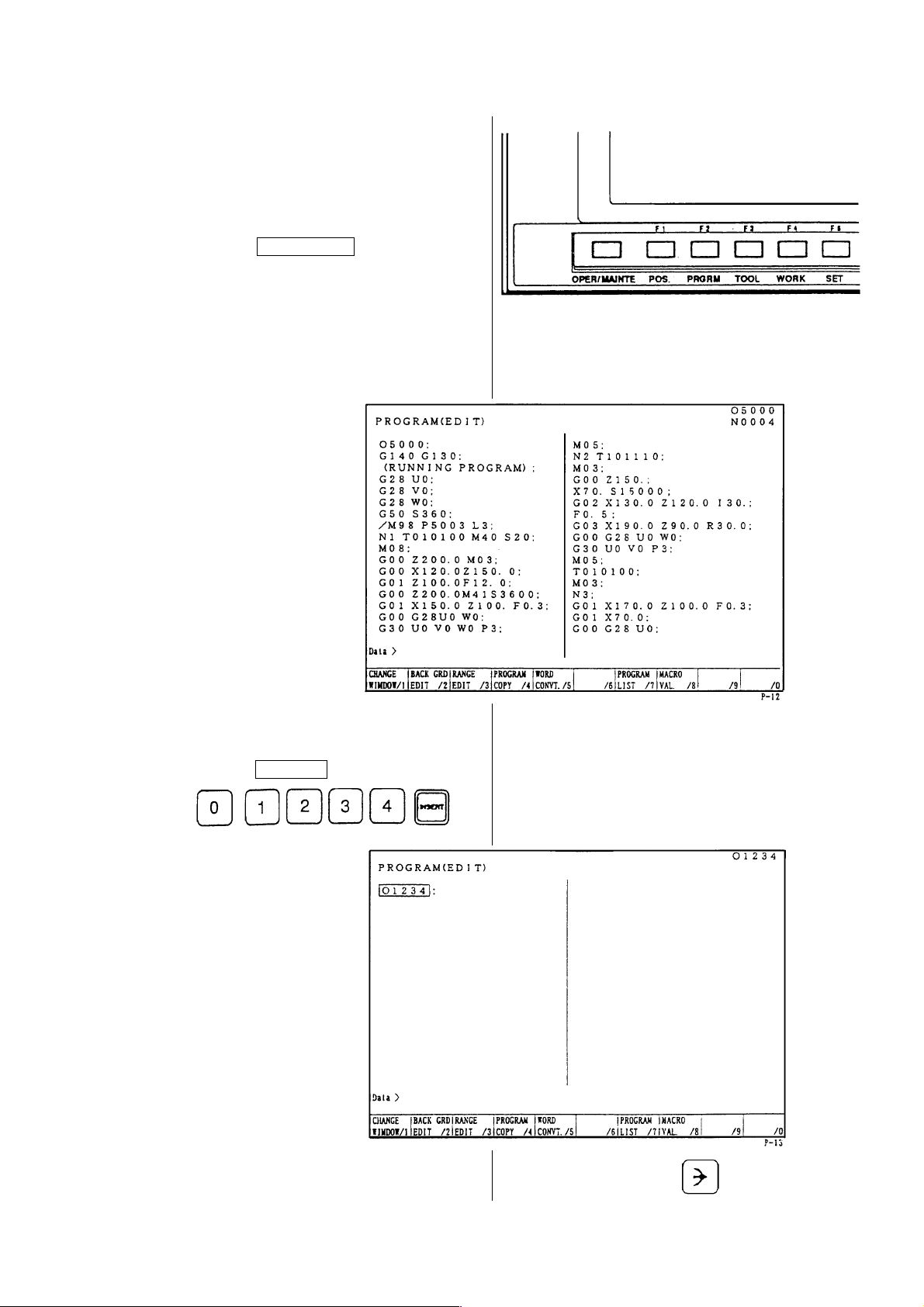
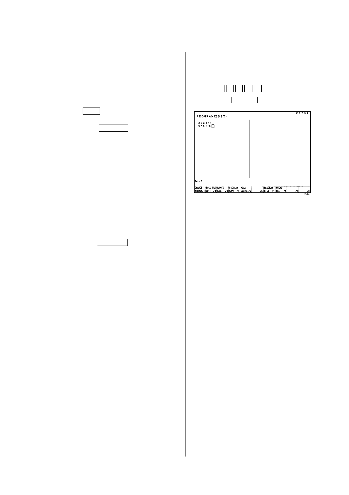
6.2 Manual registration by the address/numeral keys
1) Set a mode [EDIT].
2) Set the memory key to [WRITE].
Press the F2/PRGRM key.
3)
4) Key in a desired program No. and
press the INSERT key.
Example:
5) Set the cursor to “;’’ by the cursor key.
1 - 46
Page 55
6) Input a program according to the
order of the NC program.
Example:
Data>G28U0
• The EOB key must be inputted at
end of one block.
the
• Press the CANCEL key when the
data which has inputted want to be
deleted.
A word deletes one by one.
G 2 8 U 0
EOB INSERT
Press the RETURN key and return
7)
to the initial screen after input of all
program is completed.
1 - 47
Page 56
7 Program No. Search
There are following two methods to search a
program.
1. Search by key in a program No.
2. Search to utilize the program list.
7.1 Search by key in a program No.
1) Set a mode to the [MEMORY] or
[EDIT].
2) Set the memory key to [WRITE].
3) Press the function key
F2/PRGRM .
4) key in the program No. to be
searched and press the
Example: O 1 2 3 4
Calling up program is displayed.
O 1 2 3 4
key.
1 - 48
Page 57
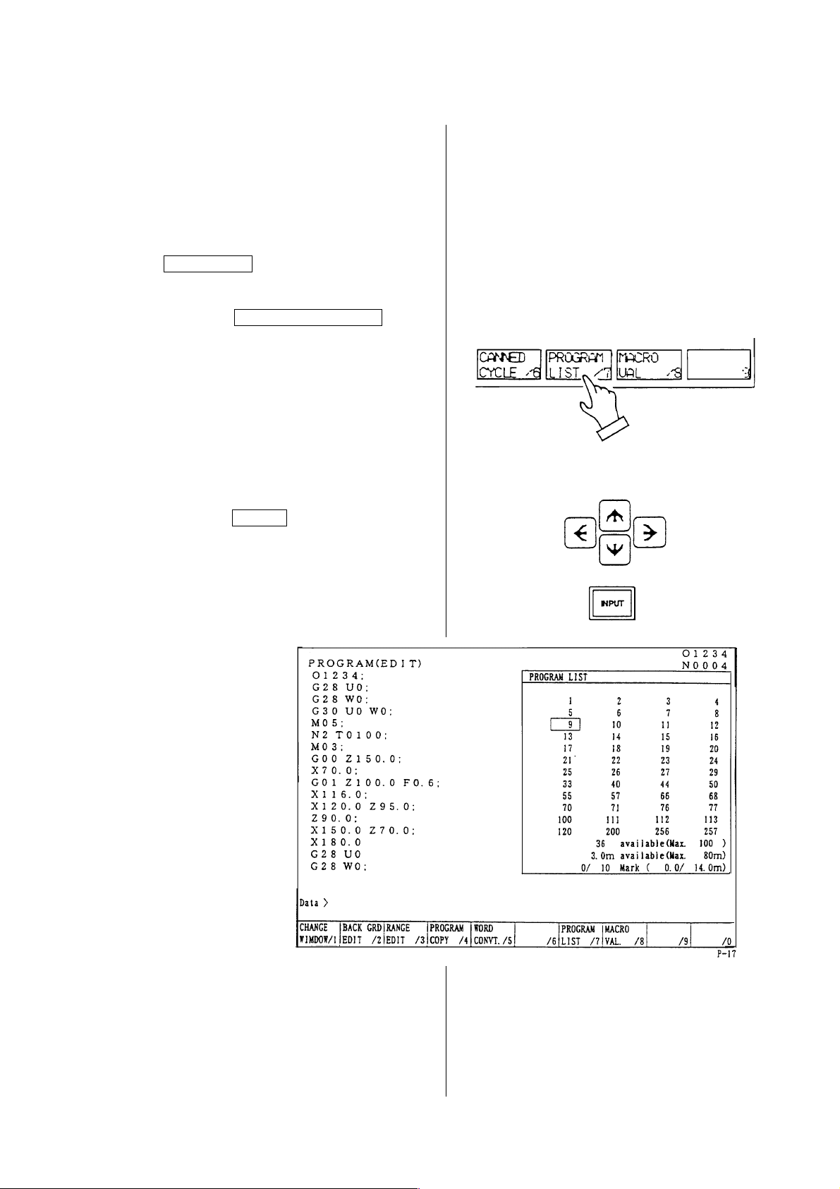
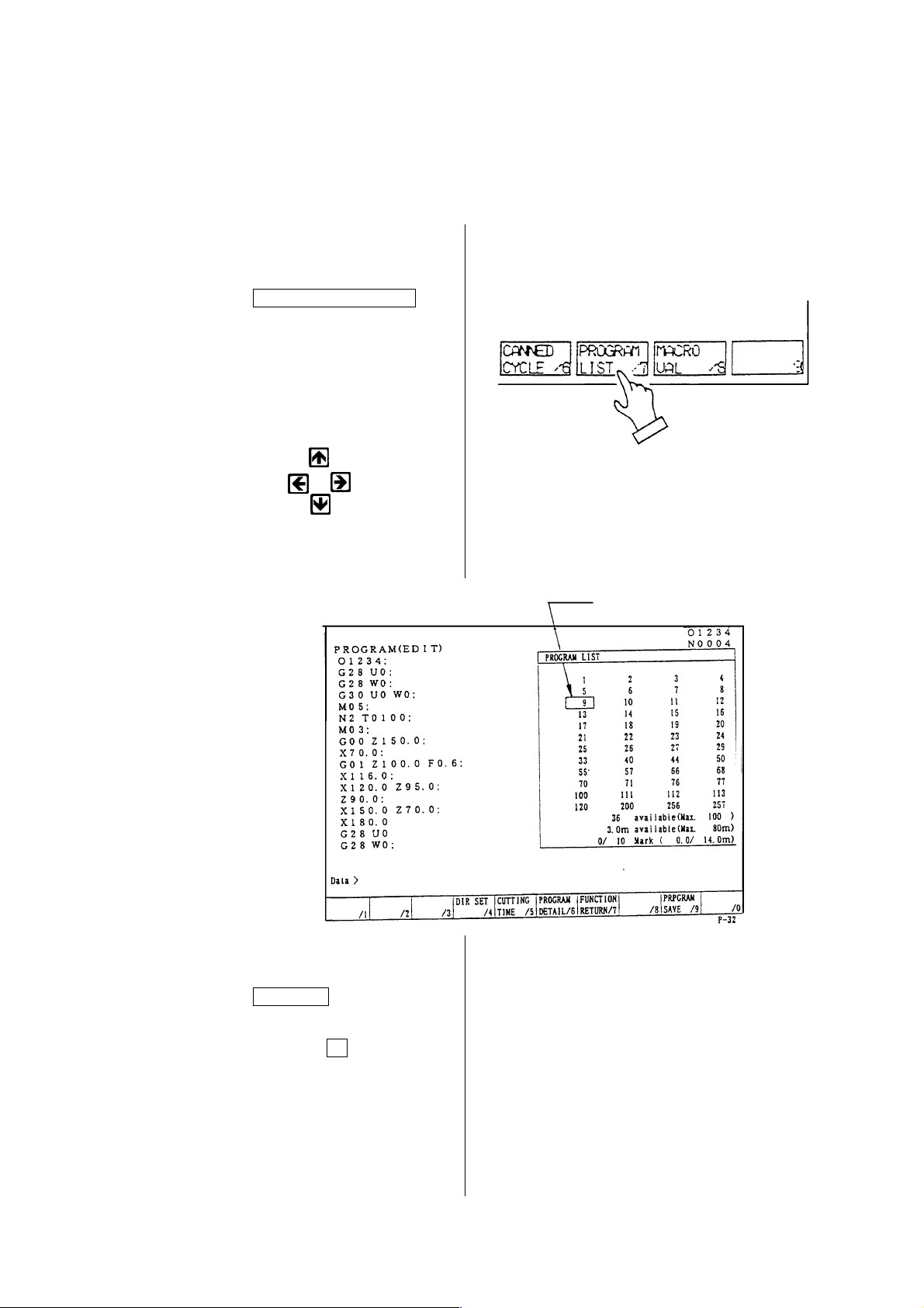
7.2 Search to utilize the program list.
1) Set a mode to the [MEMORY] or
[EDIT].
2) Set the memory key to [WRITE].
3) Press the function key
F2/PRGRM .
Press the F7/PROGRAM LIST key.
4)
5) Set the cursor to the program No. to
be searched by the cursor key and
press the INPUT key.
Calling up program is displayed.
1 - 49
Page 58
8 Edition of Program
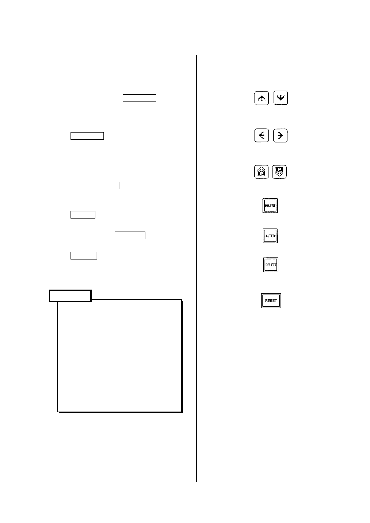
The keys to edit a program are as follows;
INSERT : Insert a content of key input after the cursor.
ALTER : Alter a content of key input at a section of the cursor.
DELETE : Delete a section of the cursor.
Use it deletion of program as well.
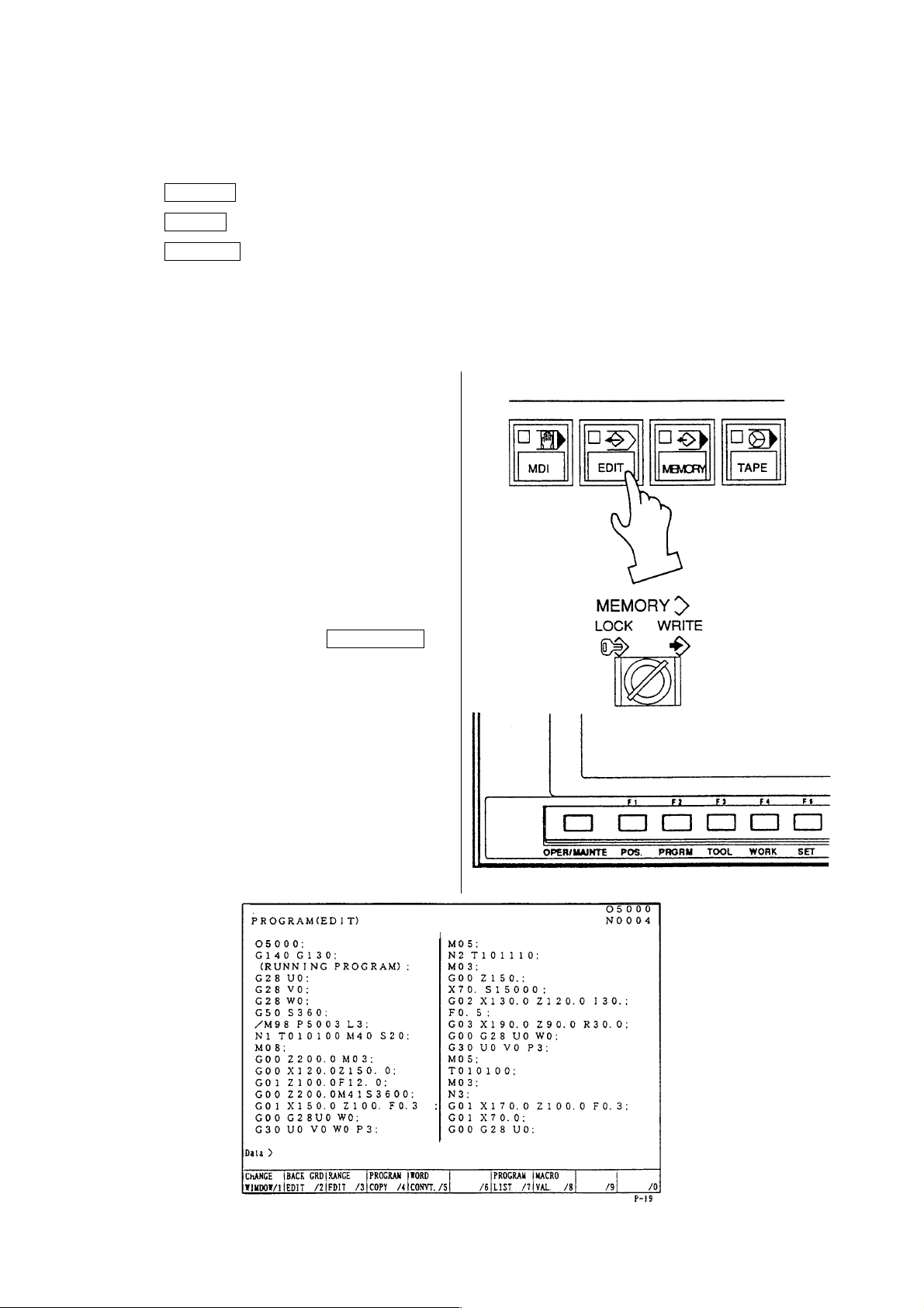
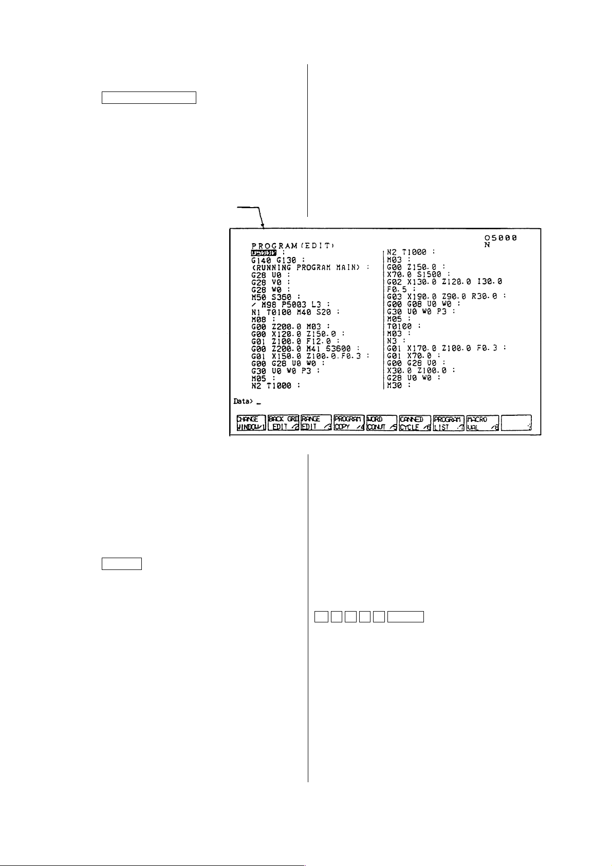
8.1 Preparation in Advance at the Time of the Edition of Program.
To edit a program, the following conditions
should be made.
1) Set a mode [EDIT].
2) Set the memory key to [WRITE].
3)
Press the function key F2/PRGRM .
1 - 50
Page 59
8.2 Search of Word
A word can be searched by the following
method.
1) A method by means of the page and
cursor keys.
[1]Press the page key and display the
page to be edited.
[2]Press the cursor key and move the
cursor to the word to be edited.
•The cursor moves at a block unit by the
keys.
•The cursor moves at a word unit by the
keys.
2) A method by means of word or address
search.
Since a message is displayed as “Not
found” if it is not found, try it again.
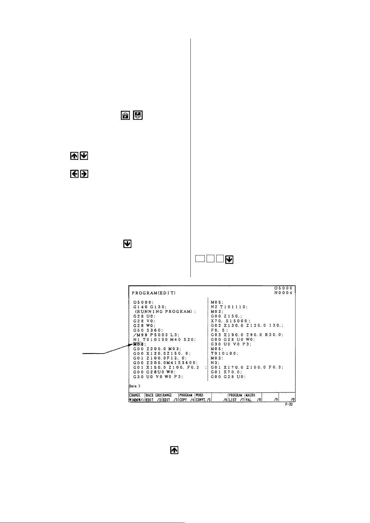
[1]Word search, No. search
Key in the address and numerals to be
searched and press
key.
Example: M08
Cursor
M 0 8
When searching a section above the
current position of cursor, press the
key
1 - 51
Page 60

[2]Block search
Check a word in a block and search a
block which contains a relevant word
only .
Key in all address and numerals of one
block then press EOB and key.
Example: When searching a block of
G02 X130.0 Z120.0 Ι30.0 F0.5;
Note)
The EOB should be inputted at the
end of a block.
G 0 2 X 1
3 0 . 0 Z
1 2 0 . 0
I 3 0 . 0
F 0 . 5
EOB
Cursor
Cursor
8.3 Edition of Program
(1) Insertion of word, block
New word is inserted just after the word
currently located the cursor.
[1]Designate a word immediately before
a section to be inserted.
[2]Key in a new data to be inserted then
press the INSERT key.
Example: when inserting X100.0 after
G00
X 1 0 0 .
0 INSERT
1 - 52
Page 61

Cursor
After insertion
Cursor
[3]When inserting one block, key in data
of one block and press EOB and
INSERT key.
1 - 53
Page 62
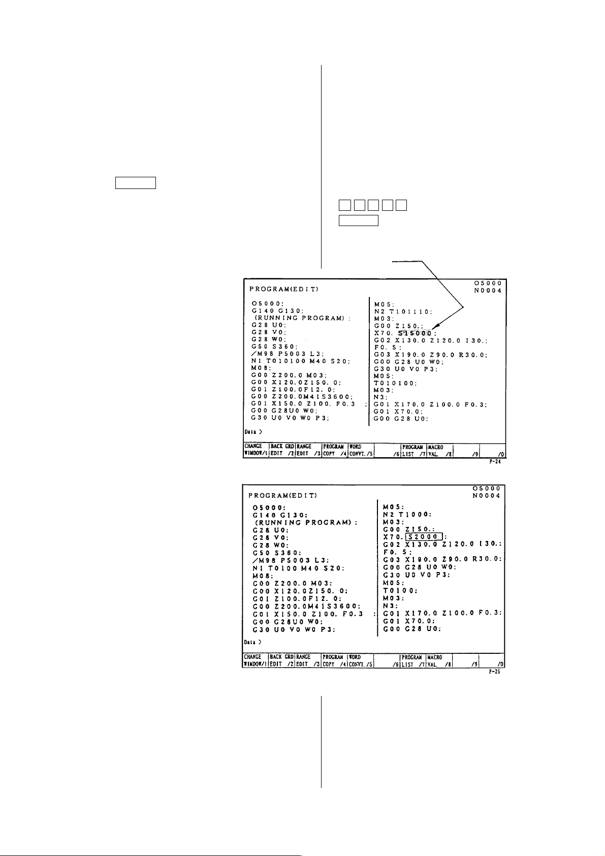
(2) Alteration of word
Alter a word, the cursor located
currently, to the new word.
Alteration is done by a word unit.
[1]Set the cursor to the word to be
altered.
[2]Key in the new word then press the
ALTER key.
Example: Alter S1500 to S2000.
S 2 0 0 0
ALTER
Cursor
After alteration
S1500 replaces S2000.
1 - 54
Page 63
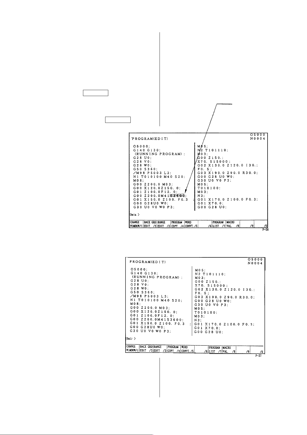
(3) Deletion of word, block
A word currently located the cursor or a
certain boundary of a program can be
deleted.
(a) Deletion of word
[1]Set the cursor to a word to be
deleted.
[2]Press the DELETE key.
Example: When deleting S3600
Set the cursor to S3600 then
press the DELETE key.
Cursor
After deletion
S3600 is deleted.
1 - 55
Page 64
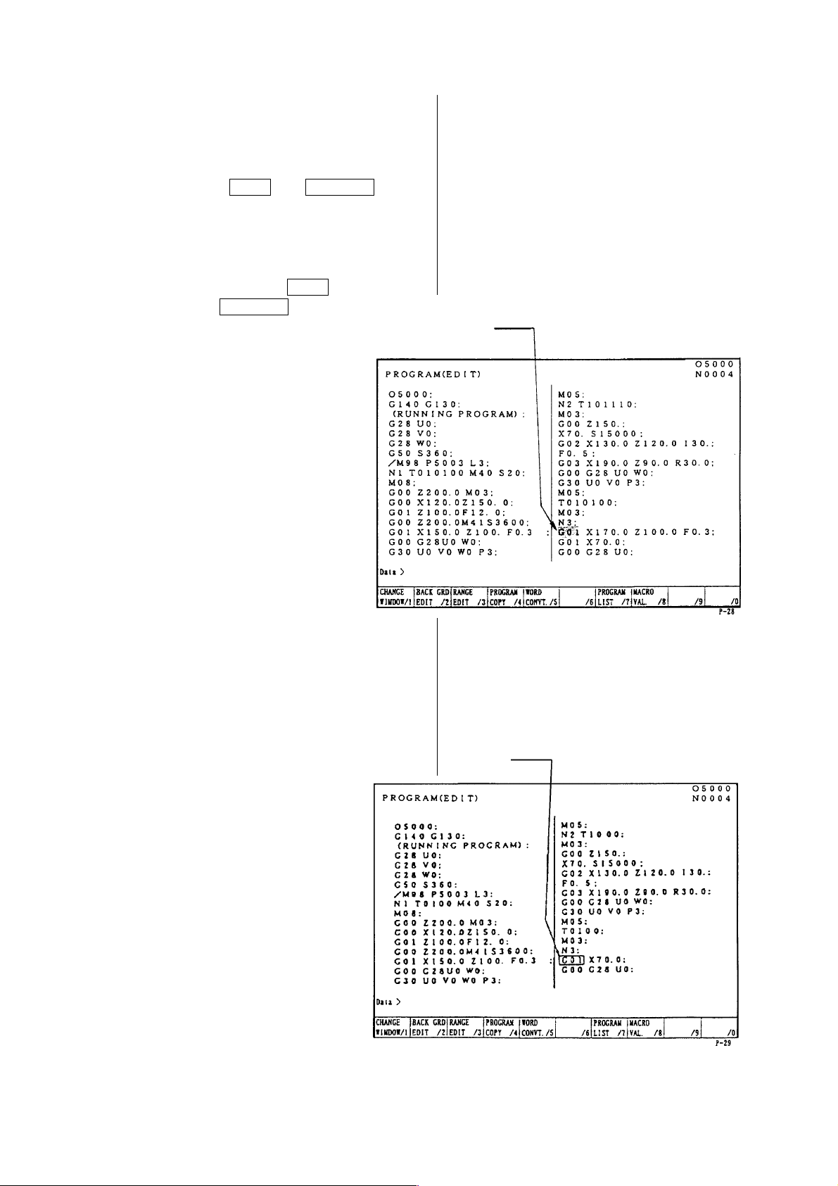
(b) Deletion of block
It can be deleted one block at a time.
[1]Set the cursor to the head of the
block to be deleted.
[2]
Press the EOB and DELETE .
Example: When deleting a block
G01 X170.0 Z100.0 F0.3;
Set the cursor to G01 and
press the EOB and
DELETE key.
Cursor
After deletion
The block G01 ... is deleted and
program moves upward.
Cursor
1 - 56
Page 65

(c) Boundary deletion
Delete blocks after the cursor to before
the designated sequence No.
[1]Set the cursor to the head word to be
deleted.
[2]Key in the sequence No. just after the
last block to be deleted and press the
DELETE key.
Note) Search the sequence No. before
deletion and check how far is it
deleted.
Example: When deleting
G00 Z150. 0;
〜
M03;
Set the cursor to G00 and
press N 3
DELETE key.
The block from the cursor
position to the just before the
sequence number N3 will be
deleted.
After alteration
The program moves upward.
Cursor
1 - 57
Page 66
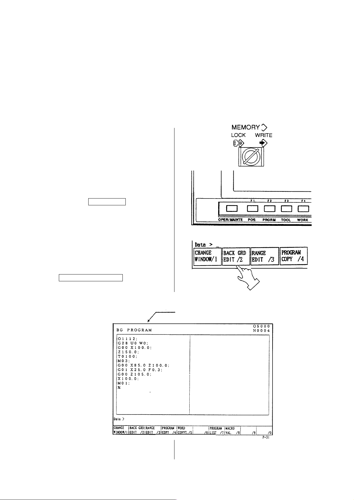
8.4 Back Ground Editing
Generally, “Editing” means front side editing, however this editing could not watch contents of
program and also edition is not available while executing a program.
In fact, giving a possibility to edit a program while executing a program is a back ground
editing.
• An editing is available to other than currently executing program.
• A program under back ground editing can not execute.
• Editing can be done both manual and automatic mode.
1) Turn the memory key to [WRITE].
2)
Press the F2/PRGRM key.
3) Press the
F2/BACK GRD EDIT key.
A title of the screen becomes a “Back
ground editing”
Title
1 - 58
Page 67

4) Search a program wanted to edit.
A procedure of search is exactly same
as a (front) editing.
Caution
Never execute a reset operation, since the machine will stops if reset is done during
machine operation at the time of back ground editing.
5) Execute edition of program.
A procedure of edition is exactly same
as a (front) editing.
1 - 59
Page 68
6) End of back ground editing
[1]Press the
BACK GRD EDIT key.
A title of screen becomes a “Program”.
It becomes normal editing screen.
Title
8.5 Copy of Program
A program being displayed can be copied
on the other number and displayed.
1) Display a program wanted to be copied.
2) Key in a new program No. and press
INPUT key.
Example: When altering to O2001
O 2 0 0 1 INPUT
1 - 60
Page 69

8.6 Editing Procedure of Range Designation (Expanded Tape Editing/Option)
Designate a range of program and this “Insertion”, “Deletion” or “Storage” can be done at the
program screen.
• Starting of range editing
Operation...... Press the F3/RANGE EDIT key.
The function changes into that for range editing.
• Designation of range
Operation...... Press the F4/RANGE SET key.
The cursor becomes a frame.
A cursor range increases by moving this. That is a range.
• Release a designation of range
Operation...... Press the F4/RANGE SET key and F3/EXIT key.
It becomes a normal cursor and a range is released.
• Storage of range
Operation...... Press the F5/RANGE STORE key.
A part of range is stored.
If a size of range exceeds 2,048 characters (approx. 5m), “Range exceeds a limit.” is
displayed and not stored.
It can be used by the range insertion at any time, since it is stored until a power turned
off.
• Insertion of range
Operation...... Press the F6/STORE→INSERT key.
Insert a part of storage after the cursor by storage of range.
• Deletion of range
Operation...... Press the F7/RANGE DELETE key.
A part designated by range is deleted.
If the size of range exceeds 2,048 characters (approx. 5m), a message “Range
exceeds limit” is displayed and the storing is ineffective.
While the source power is kept on, the stored data is maintained and the data is
available by F8/DELETE→INSERT whenever desired.
• Inserting deletion
Operation...... Press the F8/DELETE→INSERT key.
The portion stored by range deletion is inserted at the cursor position.
1 - 61
Page 70
8.7 Alteration of Word (Expanded Tape Editing)
At the program screen, search a designated word to be altered in the program and rewrite it to
a word to be altered.
There are following two methods for alteration of word.
1) Search one word each and alter if after confirmation.
2) Alter words collectively (or after words continuously with display an altering condition).
The words to be altered collectively are maximum 400,000 words.
A method to search a word is the same as the word search, words combined one character of
alphabet (or “#” mark) and numerals becomes the number search as words showing the
numeral value and recognize it with or without a decimal point.
For example, of changing “X.1” to “X.5”, a row of characters such as “X0.1”, “X0.100”, “X00.10”,
“X.1” or “X.100” which coincide with “X.1” as numeral value, become the object of alteration and
change all to “X.5”.
Also, if adding a “?” mark on the word to be changed as “X.1?” such as changing “X.1?” to
“X.5”, a row of characters “X.1” becomes the object of alteration, then “X1” becomes “X.5” and
“X.100” becomes “X.500”, however, “X.01”, “X0.100” and “X00.10” does not have the row of
character “X.1” so it does not become an object of alteration.
Outline of operation
Start alteration of word by pressing the F5/WORD CONVT. key.
[1]
INPUT in the order of a word to search and alter then a word to replace it.
If replacing word is blank, it becomes a deletion.
[2] When searching a word one by one, designate a searching direction by the cursor
and press the Y key if found a word to be altered.
[3] For altering a word contained in many places of the file collectively, designate the
searching direction by the function menu. Confirm that such overall alteration is
unmistakable, then press Y key.
Once word alteration starts, it goes on to the beginning or end of the file, depending on
the searching direction. For suspending the alteration,
Press the F5/EXIT key.
In case of the alteration of words collectively as mentioned item [3], alter it except a
row of characters in the comment. To change inside of comment, alter it by the
method [2].
,
1 - 62
Page 71

OPERATION MESSAGE
F5/WORD CONVT. ........................................ “INPUT a word to be altered.”
Input the word to be altered ........................... “Input the word to be altered.”
Input the word to be replaced ....................... “Alter word from....to....”
The words are to be searched by cursor using
keys. “Alter word from....to....”
... INPUT as it is blank ................................. “Delete a word......”
...Alteration of word will be completed even if pressing the CANCEL key from • mark.
...Designate a searching direction of word by
...If it is not found ........................................... “Not found”
...“Search by cursor
...If it is found ................................................. “Alter a word....to....”
...Alter by Y key.
F1/BLANKET ALL Regardless of cursor position, searching starts with the
F2/BLANKET BEFORE Searching takes place in the forward part following the
F3/BLANKET AFTER Searching takes place in the backward part preceding
, .”
program head.
cursor including the word with the cursor.
the cursor including the word with the cursor.
, key.
,
...By operating , keys collective alteration starts.
...Alteration is executed by pressing Y key.
When alteration has be completed ................ “Word replaced”
When the word is not found........................... “Not found”,
.............. “0 word replaced”
Press F5/EXIT key. ...................................... “Alteration suspended”
1 - 63
Page 72
8.8 Deletion of Program
There are following two methods to delete a program.
1. Delete it by the program list screen.
2. Delete it by key input at the program screen.
1) Deleting method by the program list
screen.
[1]
Press the F7/PROGRAM LIST key
at the program screen.
[2]Set the cursor at the program to be
deleted by the program list.
Press the cursor key.
Press the DELETE key.
[3]
[4]Against a message “Is it all right to
delete ?”, press the Y key if you
agree.
Cursor
A program which is designated by the
cursor is deleted.
1 - 64
Page 73

2) Deleting method by key input
[1]Display the program screen.
[2]Key in the program No. to be deleted
and press the DELETE key.
Example: In case of deleting O100
[3]Against a message “Is it all right to
delete?”, press the Y key if you agree.
A program keyed in is deleted.
3) Continuous deletion by Program No.
[1]
Press F7/PROGRAM LIST .
[2]Place the cursor at the Program No.
to be deleted then press SPACE .
An asterisk marked at the head of the
Program Nos. selected.
Example: Screen display shown below
is the case of deleting
Program
Nos.O100, O111, O169, O200.
Press the DELETE key.
[3]
O 1 0 0 DELETE
For deleting the entire program,
press ORIGIN and DELETE keys.
8.9 Arrangement of Program
When editing a program, a size of program becomes larger than actual size occasionally.
In this case, available memory can be increased a little by arrangement of program.
This operation is called “Condensation”.
Operation ••• Confirm that it is in the editing mode, not background editing, and NC is in
reset condition. (When there is secondary series or background drawings, it
must also be in reset condition.)
Press the F1/CONDENSE key.
A message “Condensing” appears on the display, then after a while, it
changes to “Condense complete”.
It takes several seconds to several minutes to complete condensation,
depending on the size of memory and the condition of memory usage. If any
key is touched during condensing, the message “Condensing” disappears
and the process is suspended.
1 - 65
Page 74

Caution
If source power is switched off during “Condensing”, the program is destroyed. When
program is found to be abnormal, initialize the program memory, then arrange program
input anew.
8.10 Process After Edition
Press the RETURN key.
Return to the initial screen.
1 - 66
Page 75

9 Output of Program
NC program can be outputted to the external in/output equipment.
1) Connect an output device to the RS232-C terminal and make it ready.
2) Make a mode selection to [EDIT] mode.
3) Set the memory key to [WRITE].
4) Press the function key
F8/IN/OUT .
Note) When “Dondon FD” is on the
screen display, press the
F5/DONDON FD COMPLETE
key, and get the “Data Output”
screen.
Refer to the instruction manual of output
device.
A right sketch is displayed.
1 - 67
Page 76

5) By pressing F7/ LIST CHANGE key,
The display of Program No. List is
switched over to that of Program No.
Detail.
O To select Program No.
Place the cursor at the Program No.
to be selected then press SPACE .
An asterisk is marked at the head of
the Program No. selected.
When selecting all programs, repeat
pressing ORIGIN several times until
the mark “*” is displayed.
Example: O5, O6, O7.
Press the F2/IN/OUT , and
5)
the selected program is output.
6)
Press the RETURN key after
completion of output and return to the
original screen.
1 - 68
Page 77

10 Setting of Tool Compensating Amount
A tool compensating amount is set automatically by touching a tool tip to the sensor of Qsetter. In this chapter explains a setting method of tool compensating amount by manually.
10.1 Setting of T ool Compensating Amount
1) Select the manual mode.
or
2) Set the memory key to [WRITE].
Press the function key F3/TOOL at the
3)
initial screen.
Cursor
A right sketch is displayed.
1 - 69
Page 78

a) Tool offset data has geometry and
wear offset for each offset No.
respectively.
Tool compensating amount by the Qsetter is inputted in the column of
geometry offset.
b) A cursor moves up and down every
time of pressing the cursor key.
c) Each address is as follows;
X : Compensating amount of
diametrical direction
Z : Compensating amount of
longitudinal direction
R : Size of nose R
T : Nose point
H : Compensating amount of groove
width
U : Incremental compensating
amount of diametrical direction
W: Incremental compensating
amount of longitudinal direction
Q : Incremental amount of nose R
J : Incremental compensating
amount of groove width
4) Set the cursor to the tool No. to be set a
tool compensating amount and address.
5) Key in a compensating amount (setting
amount) and press the INPUT key.
Compensating amount (setting amount)
has a decimal point and minimum unit is
0.001mm.
If a geometry offset is inputted, a wear
offset amount being stored so far
becomes zero.
Note 1) A wear offset amount beyond
1mm can not be inputted at one
time.
divide a compensating amount
within 1mm and input it by several
times.
2) Wear compensating amount can
be inputted at any mode.
3) Wear compensating amount adds
every input.
1 - 70
Page 79

10.2 Deletion of Tool Compensating (Setting Amount)
1) Select the manual mode.
2) Set the memory key to write.
3) Set the cursor to the offset No. to be
deleted.
4)
Press the F7/ DATA CLEAR key.
Deleting items are displayed on the
screen.
• One tool deletion : Delete whole setting amount of offset No. designated by the
cursor.
• Geometry (All tools) : Delete geometry setting amount of all offset No.
• Wear (All tools) : Delete wear setting amount of all offset No.
• All data : Delete all setting amount.
5) Set the cursor any of deleting item.
6)
Press the INPUT key.
Asking a question whether delete or
not.
Press the Y key when deleting.
7)
(Press the N key when not deleting.)
A setting amount to be deleted is
deleted.
Note) In case of execution of one tool deletion, it is required to set the cursor to the
Offset No. to be deleted before pressing the F7/DATE CLEAR key.
To change an offset No. after display a deleting item, press the
F7/DATA CLEAR key once and return a previous screen then set the cursor to the
No. to be deleted again.
1 - 71
Page 80
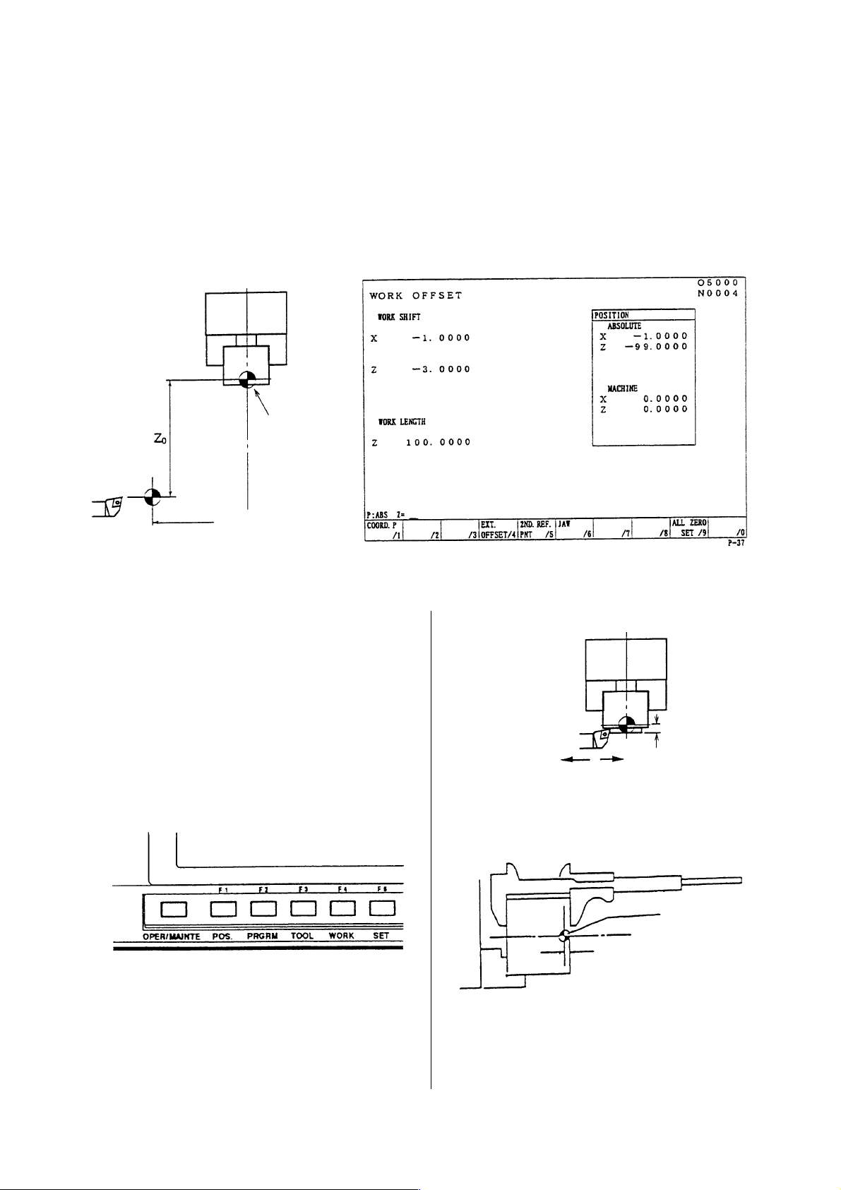
11 Setting of Work Coordinate System Shift Valve
1 1.1 Tool Tip Position Setting of Standard Tool at Machine Zero Point.
Must be obtained a tool tip position by setting of the X axis work shift amount, how much
apart a tool tip position of the standard tool at the machine zero point from machining zero
point (X0, Z0) before execute a program check or machining by a program, and input it to the
NC unit.
Machining zero
X0 Z0
Shift amount setting procedure of Z axis
work shift coordinate system.
[1]Chuck a workpiece and turn an end
surface of workpiece by manual mode.
Note) Never move on the Z axis at the
time of retracting a tool.
[2]Stop the spindle.
[3]Display a work coordinate system screen.
[4]Measure a total length of a work-piece
and get a cutting amount
.
Cutting amount
Direction of retracting tool
Machining zero
X0 Z0
Cutting amount L
Example
=1.35
1 - 72
Page 81
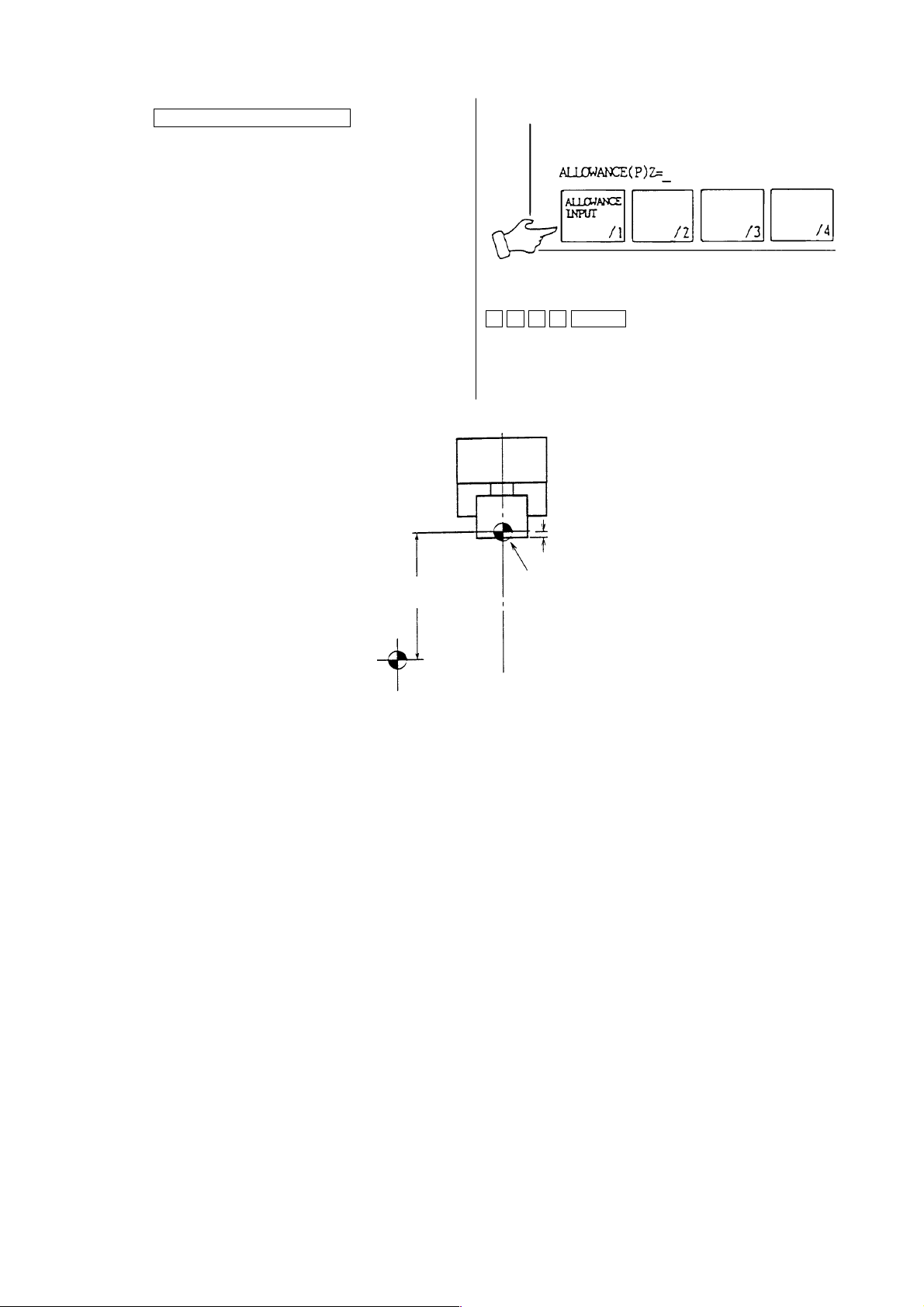
[5]Press the function key
F1/ALLOWANCE INPUT .
“Allowance (P) Z = ” is displayed on the
lower left of the screen.
[6]Input the cutting allowance (Allowance).
It is written at the “Z” of the machining
reference point shift automatically.
“Z0” shift amount of the
work corodinate
Machine zero
1 . 3 5 INPUT
Cutting amount(1.35)
Machining zero
[7]Execute zero return.
Note 1) The following operation must be executed if execute input or alteration of cutting
amount (Measured value).
Set up is done by executing the following operation, the distance from machine zero
to the tool tip point is displayed properly.
a) Manual zero return.
b) Manual index.
c) Command and execution of T
2) Direct input (Z
∆∆∆∆
) or addition and reduction (Ι = Incremental input Z =
∆∆∆∆
by a program (MDI is available as well.).
∆∆)
are
available as usual.
3) A work shift amount of X axis has set by the parameter already.
See the display of the machining reference point of the work coordinate system
screen to confirm.
1 - 73
Page 82
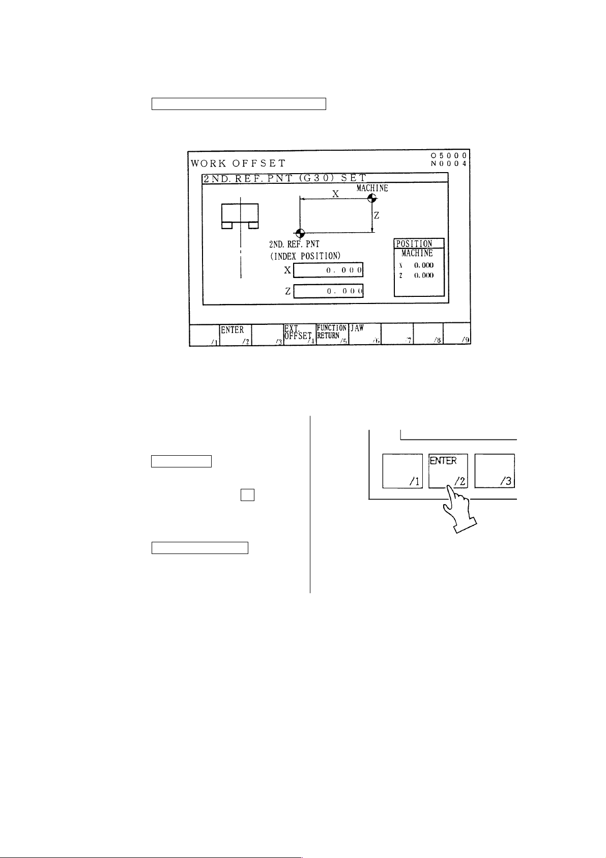
1 1.2 Setting of 2nd Origin Point
A 2nd Origin Point is easily set as follows.
1)
Press the F5/2ND ORIGIN POINT RETURN key.
2) Move the tool rest to the position where
the 2nd Original Point is to be set, by
handle operation or jog feeding.
3)
Press the F2/ENTER key.
Answering the query “YES (Y) OR
NO(N)”, if affirmative, press Y key.
Setting of 2nd Origin Point now
completes.
4)
Press the F5/WORK (DATA) key to
return the initial screen display.
1 - 74
Page 83
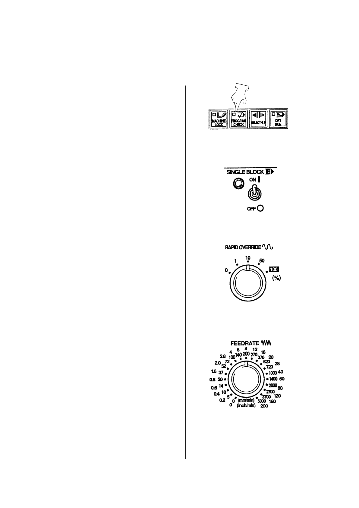
12 Automatic Operation
12.1 In Case of Machining of the First Workpiece with Confirmation of Newly
Produced Program
[1]Program Check Operation
Move the machine by a program without
the spindle rotation and check a tool
movement, interference of tool and
contents of a program.
Preparation before program operation
1) Call a program.
2) [LOCK] the memory key.
3) Check the input of tool position offset,
tool tip point and tool nose R properly.
4) A workpiece should be off.
5) Set the switch of the operation panel as
shown the right sketch.
• Program check mode
• Single block
• Rapid traverse override at 10%
Operation
1) Set a mode key to [MEMORY].
2) Press a program screen key.
3) Press a reset key.
4) Program start (After checking of motion
of one block, preys the [START] button
again and proceed a program
consecutively).
5) Adjust a “Feed speed” by a feed speed
dial.
6) Check a motion until end of a program.
7) Press a “Program check” and release if
all motion is correct.
1 - 75
Page 84

[2]Test Cutting
Cut a workpiece by single block mode if
no trouble is found by program check.
1) Press key set as right sketch.
• Single Block [ON].
• Optional stop [ON].
• Rapid traverse override at 10%
2) Chuck a workpiece and check run out
of a workpiece by pressing the
spindle inching key.
3) Close the door.
4) Press a program automatic operation
key. (Press the [START] button again
after checking of motion of one block
then proceed a program
consecutively.)
5) Adjust a spindle override and
federate override by watching a
cutting condition. (After that modify a
program.)
6) In case of motion of axis want to be
stopped, press a [HALT] button.
7) At the time of completion of
machining of one tool, stop the
machine by “M01” then check a
dimension.
1 - 76
Page 85
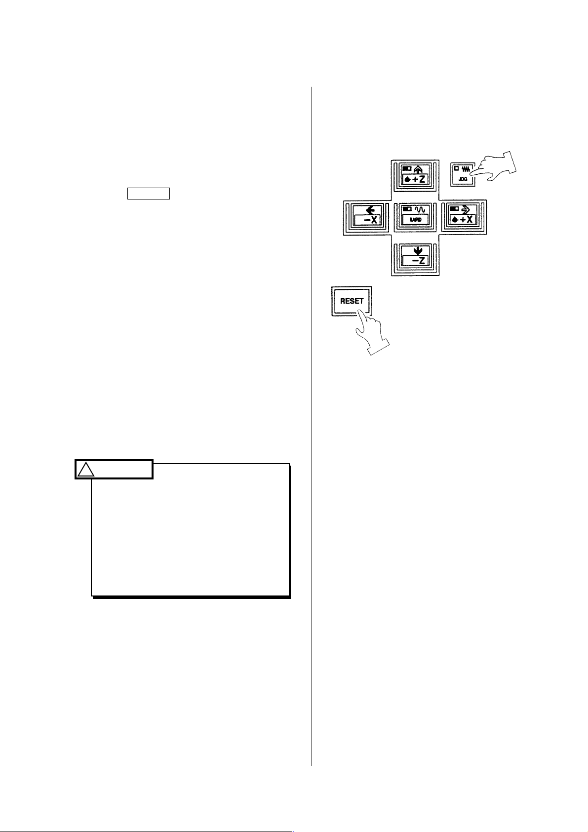
12.2 Start from Middle of a Program
Operation method in case of program edit
and restart when a program is stopped by
an alarm etc..
1) Retract the tool from the workpiece by
handle or feed.
2) Stop spindle rotation and coolant and
press RESET button.
Reset a program.
3) Check a cause of an alarm and treat it.
4) Set a mode to the [MEMORY].
5) Heading the program on the “Program”
screen.
(Press the reset button.)
6) Search a sequence number of a tool to
be restarted.
Restart from the beginning of process.
Restart should always be done from the
beginning of tool arrangement. Never
restart midway of machining process, as it
is dangerous.
WARNING
!
1. Don’t touch the tool by hand
during spindle rotation.
2. Press program [STOP] or
[EMERGENCY STOP] button if
the machine moves unexpected
direction or unexpected condition
is occurred.
1 - 77
Page 86
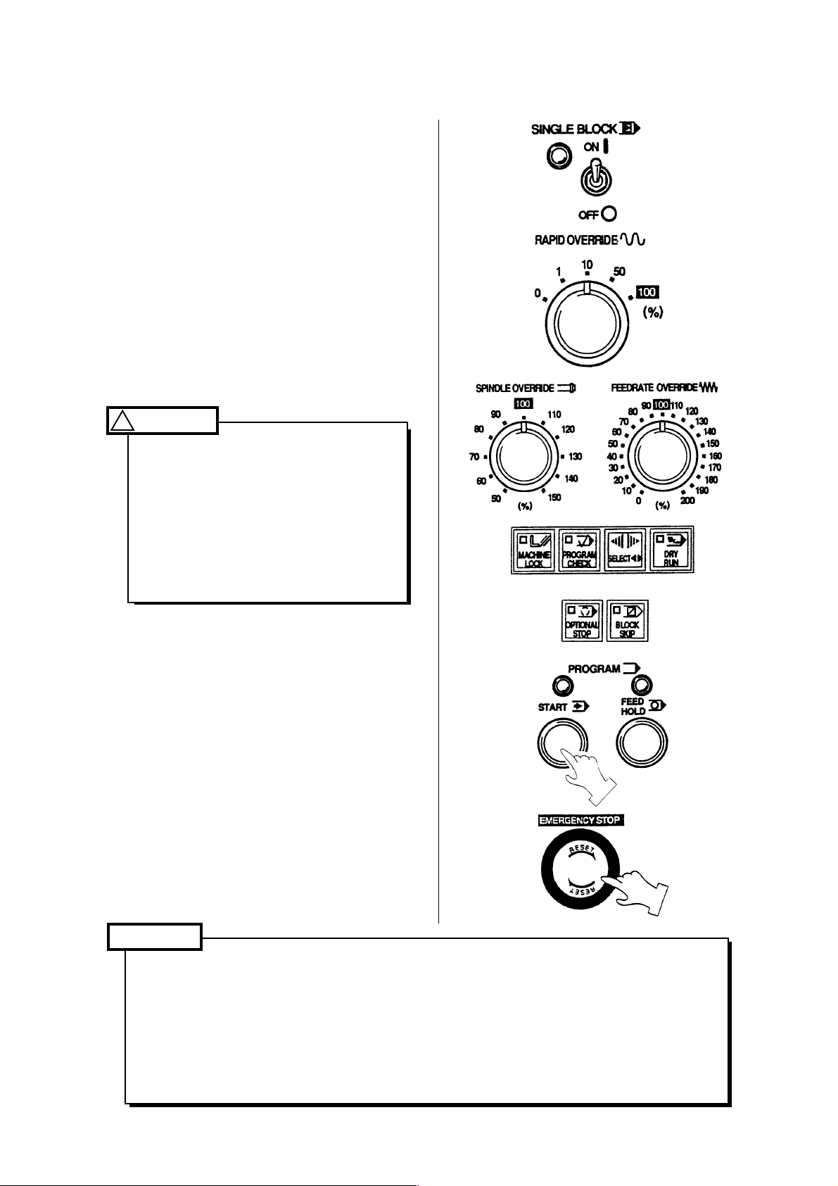
12.3 Continuous Machining Operation
1) Set each switch on the operation panel.
[1]Turn “OFF” the single block switch.
[2]Set the override switch of federate and
spindle at 100%.
[3]Set the rapid traverse override at 100%.
[4]Turn off dry run, tape check and
machine lock. (Lamp is turned off)
[5]Set the switch of optional stop or block
skip if necessary.
2) Press program [START] button.
WARNING
!
In case of temporary stop is required
during operation, press program
[HALT] button or turn “ON” single
block switch.
Also, if unexpected condition occurs,
press [EMERGENCY STOP] button
and stop the machine immediately.
Caution
1. When rotating the spindle, the command should initially be adjusted at a low speed
(rpm abt. 100) and, by operating the inching key, confirm the sway condition of the
workpiece.
2. In all circumstances, for safe cutting, the upper limit of spindle rpm is set in the
program. Especially when special jaws such as high jaw or some special fixing
device are attached to spindle, a safe revolving speed should be programmed for
the spindle rotation.
1 - 78
Page 87
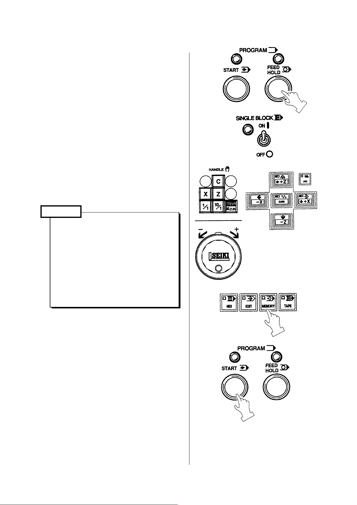
12.4 In Case of Insertion of Manual Operation During Automatic Operation
1) Press program [HALT] button and stop
the machine temporarily (Red lamp,
upper right of halt button, is it) or stop by
turn [ON] single block switch.
2) Shift a mode switch to [HANDLE] or
feed and execute manual operation.
Start the spindle if spindle stop is
executed.
3) Return mode to [MEMORY] after
completion of manual operation.
4) If pressing the program [START] button,
the program restart.
Caution
1. At first, execute an automatic
operation by the single block.
Enter the continuous operation
after confirmation of motion of the
tool head etc. are correct.
2. [FEED HOLD] button, action of M,
S and T function is continued until
end of the motion. If motion is not
completed, manual operation is
not available.
1 - 79
Page 88

12.5 In Case of MDI Operation in Middle of Automatic Operation
1) Turn [ON] the single block switch on
operation panel.
2) Shift a mode to [MDI] after machine
motion is stopped.
3) Display the program operation screen by
pressing the program key.
4) Input a required action by address keys
and numeral keys and press the
INSERT key.
5) Press the program [START] button after
confirmation of input data of [MDI].
6) To restart automatic operation, shift a
mode to [MEMORY] and turn [ON]
single block switch.
1 - 80
Page 89
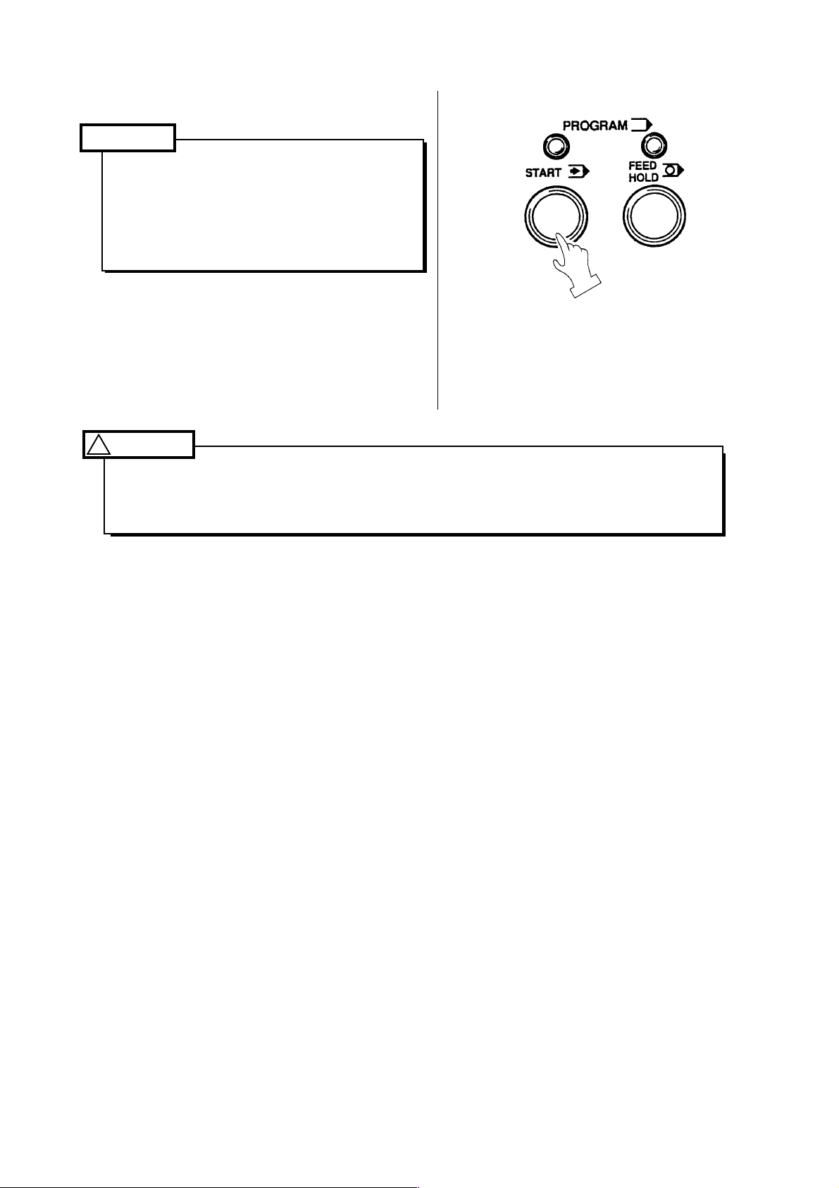
7) Press the program [START] button.
Caution
At first, execute an automatic
operation by the single block.
Enter the continuous operation after
confirmation of motion of the tool
head etc. are correct.
WARNING
!
If continue an automatic operation after inputting only by MDI and not executed it,
unexpected motion may occur due to contents of buffer by automatic operation is
replaced with unexecuted buffer contents of MDI. Pay attention to danger.
1 - 81
Page 90

13 Setting (Data)
13.1 Outline
Various setting data required to operate the machine can be set.
The setting (Data) screen is displayed by pressing the F5/SET key.
In this screen, parameters frequently used are classified together by item or purpose for easy
setting.
An option is not displayed if it is not provided.
Since it consist of several pages, change it by pressing the page key
key corresponding a menu at the left side of the screen.
The number search also available.
Setting (Data)
or alphabetical
(1) Display and setting
In case of a selection such as “Do/Don’t”,
you want.
Set the cursor by the cursor key and press the INPUT key.
Further, when the cursor key
HITACHI SEIKI’s standard is the left side.
Numeral data is set through the key input area. Needless to say, calculation and absolute/
increment value input are also available.
is pressed, it moves at the side of • mark. The
• makes are on at the side of setting has done if
Caution
Input limit for writing key etc. is not applied on the setting screen is different from the
parameter screen, change it with fully attention by an operator himself.
1 - 82
Page 91
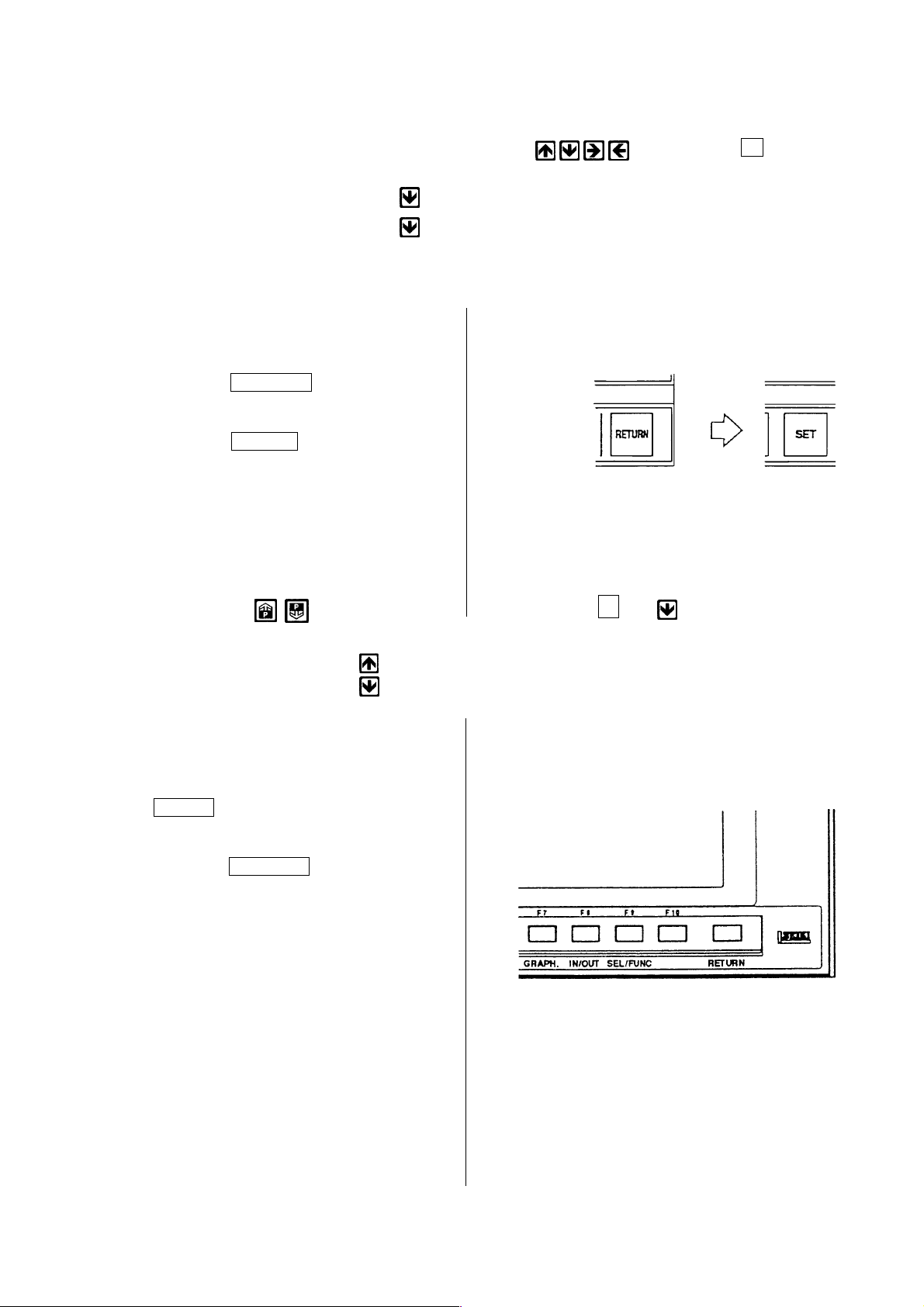
(2) Number search
Since all pages have serial number, a page or cursor can be moved at once by the number
search. A search executes by pressing a cursor key after inputting N and
following numerals.
Example N: Number = 12 (Move to No.12)
N: Number = 1 + 10
(3) Setting method
1. Set the key switch for writing of memory
to write side.
2. Select the setting data screen.
Press the RETURN key.
Press the F5/SET key.
3. Set the cursor to the item to be changed
by the page and cursor key or number
search.
Press the page key and
display a section to be or, input the setting number.
changed.
(Move to No.11)
N ∆ ∆
4. Key in a desired numeral and press the
INPUT key.
press the RETURN key and display the
5.
initial screen after completion of setting.
1 - 83
Page 92

13.2 Stored Stroke Limit
This machine has a stored stroke limit which can be set an entry prohibition of a tool in the
movable zero of the machine (in the stroke of the machine) for more safety either automatic
or manual operation.
A stored stroke limit function becomes effective on the axis which has executed a zero return
of the turret.
This function differ from a mechanical stroke end and there are following three types.
(1) The first stroke limit
This is set at the maximum stroke of the machine by the parameter and is not changeable.
Outside of rectangular always prohibit an entry by the parameter setting of the point A and B
by the distance from the machine reference point as following sketch. Generally, this
parameter is not allow an alteration.
Point A
Point B
Z (− )
Machine reference point
X (− )
Entry limit zone
1 - 84
Page 93

(2) The second and third stroke limit
Set the second and third stroke limit at any places without restraint by commanding a
distance and direction from the machine reference point. It can be selected either inside or
outside as well.
-310
-X
D
-180
The second
stroke limit
(inside)
-450
C
-300
Machine reference point
150
The third stroke
limit
(inside)
F
-Z
1100
-130
E
-310
[1] Selection of stroke limit
Selection of a stroke limit whether inside or outside of the frame fixed by C, D and E, F
can be done by the parameter No.1300~ .
Inside of a frame fixed by the point C and D of
0
No.1300-0 bit
the second stroke limit is a prohibited zone.
Outside of a frame fixed by the point C and D of
1
the second stroke limit is a prohibited zone.
Do not check the second stored stroke limit of
0
No.1310-0 bit
each axis.
Check the second stored stroke limit of each
1
axis.
Do not check the third stored stroke limit of each
0
axis.
No.1310-1 bit
Check the third stored stroke limit of each axis.
1
1 - 85
Page 94
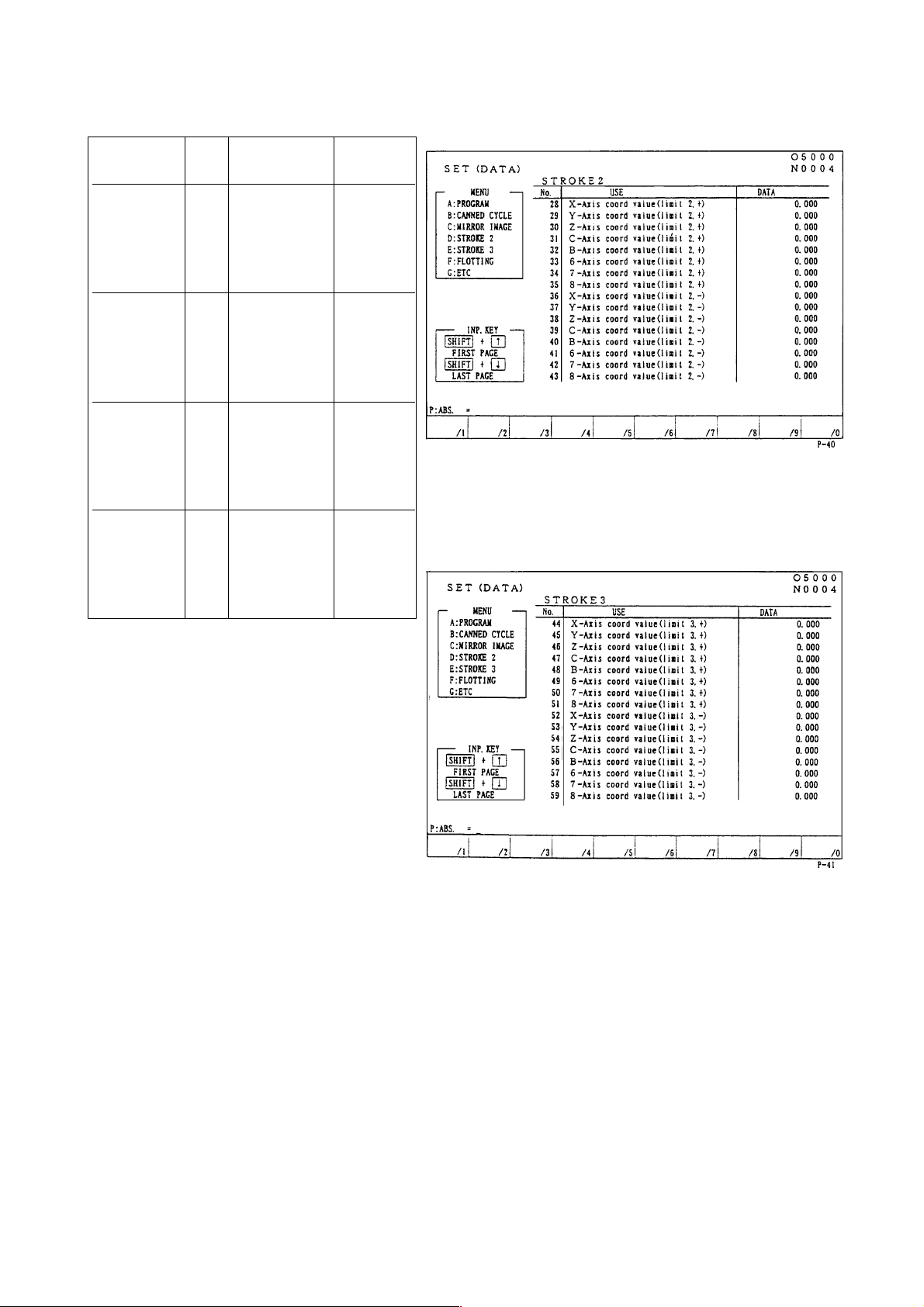
[2] Setting of limit by setting data and check
Prohibited
zone
The second
limit,
+ direction
The second
limit,
- direction
The third
limit,
+ direction
The third
limit,
- direction
No.
28
29
30
31
32
36
37
38
39
40
44
45
46
47
48
52
53
54
55
56
Setting
position
X of point C
Z of point C
X of point D
Z of point D
X of point E
Z of point E
X of point F
Z of point F
Setting
example
-5.000
0.000
-310.000
0.000
0.000
-480.000
0.000
-500.000
0.000
0.000
-170.000
0.000
-10.000
0.000
0.000
-490.000
0.000
-120.000
0.000
0.000
Note) The value of X-axis is diametrical
value command.
1 - 86
Page 95

[3]The third stroke limit setting by MDI or program command
Example:
G22 X-170.0 Z-10.0 I-490.0 K-120.0
An entry prohibition command into the second and third stroke limit and set the third
stroke limit.
Example:
G23
Entry into the second and third stroke limit becomes available.
Refer to the programming manual for for details by program command.
Note) 1. If G23 has commanded, G22 should be commanded in an individual block to
make an entry prohibition inside of setting zero zone again.
2. The value of setting data is automatically altered if G22 X
commanded.
3. When manual reference point return is executed after power on, entry
prohibition into a zone becomes effective immediately.
4. If the turret enter into the prohibited zone by manually, move it opposite
direction to escape from prohibited zone.
The NC reset key should be Pressed after an escape.
5. During automatic operation, if the end point of travel locates in the prohibited
zone, an alarm issues before the movement (According to the NC parameter,
an alarm issue after the movement) and stop the automatic operation.
If the turret enter into the prohibited zone, move it opposite direction to
escape from prohibited zone.
The NC reset key should be pressed after an escape.
Z I K is
1 - 87
Page 96
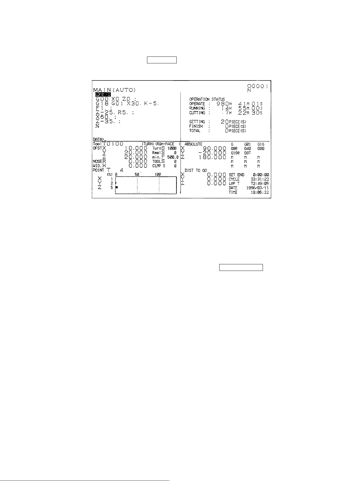
14 Time Measuring, Data
Machining time and cutting time are displayed at the lower right of the general screen.
It can be displayed by pressing the RETURN key.
14.1 Time Measuring
Four type of time is measured at the lower right of the screen. It can be measured in the
limit of less than 10,000 hours.
Input in here execute by moving the cursor after pressing the F9/SEL/FUNC key
Example: (Hour/Minute/Second) = 0 (Set to zero)
(Hour/Minute/Second) = 1 (Input as 1:00:00)
(Hour/Minute/Second) = 1/2 (Input as 1:02:00)
(Hour/Minute/Second) = 1/2/3 (Input as 1:02:03)
(1) Prearrangement of completion
Advance notice of completion becomes effective at the time of the
“SET END TIME’’ key on the operation panel of the machine is on.
A time of a prearrangement of completion is a time from start to the time of a advance notice
of completion at the automatic operation.
If an operator inputs a time of a prearrangement of completion of a program, inform it by call
light when a machining time reaches to the prearrangement of completion.
(2) Machining time
Accumulate a time during machining. (A time of the start lamp is being on.)
1 - 88
Page 97

(3) Cutting time
Accumulate a time during cutting feed. (A time during cutting feed by G01, G02 or G03)
(4) Lap time
Measure a lap time between a tool and tool. At the time of tool change set it to zero
automatically. Measurement does not execute while the NC is stand by condition.
14.2 Date and Time
The date and time is displayed by the clock builted in.
The date shows by A.D. and time shows by 24 hours. (1 p.m. is 13 hours.)
Since it is backed up by a battery, it moves even if the power is turned off.
Do not change it unnecessarily, however, if discrepancy of the time has occurred from one
cause or another, it should be set correctly because it uses at the time of periodical check.
OPER/MEINTE → F4/SYSTEM → Date/hour screen appears with date/hour setting.
1 - 89
Page 98
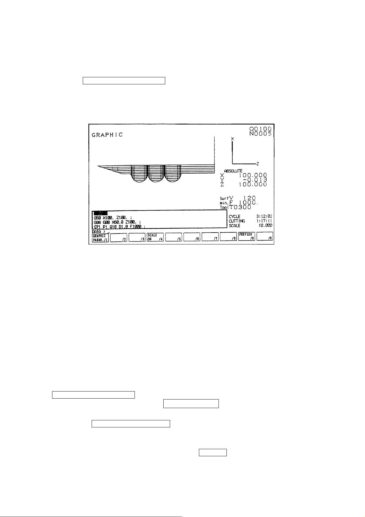
15 Animated Drawing
15.1 Outline
When the F7/ANIMATED DRAWING key is pressed, the animated drawing screen is
displayed.
Animated drawing of a locus of a tool is executed here. Also, the following data are
displayed for the reference of animated drawing.
O Animated drawing plane of parameter
O Tool tip position
O Rotation S, Feed F, Tool command T
O Machining time, Cutting time
O List of programs currently under execution
A locus is drawn based on a value of the tool tip coordinate system.
Since a moving point becomes unclear if drawing consist of plenty of lines, a tip is expressed
by a small point.
Normally, synchronous drawing is displayed. For pre-processing drawing, press the
F9/PREPROCESS DRAW key and get the display of the list of function keys for preprocessing drawing. Then, press the F3/DRAWSTART key and pre-processing drawing will
start.
Pressing the F2/AUTORANGE DRAW key, pre-processing drawing will start and the
drawing range is set in such a way that the locus of the cutting feed is properly shown within
the frame of the screen when drawing finishes.
For canceling the display of a drawing, press the ORIGIN key.
Following setting can be done for drawing. Refer to the following item for details.
1 - 90
Page 99
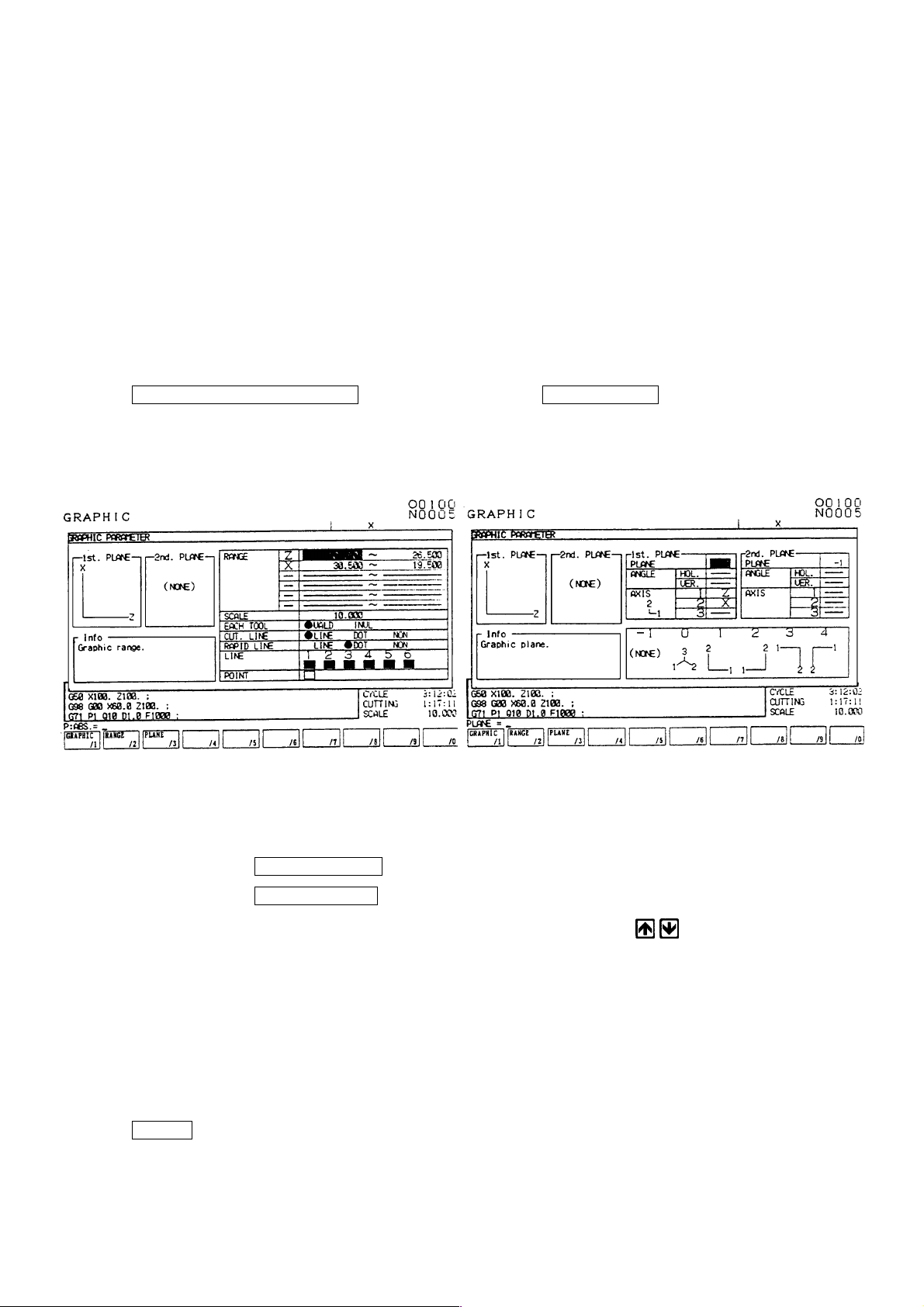
O Selection of drawing plane
O Indication of rotating angle (Horizontal, Vertical)
O Drawing zone (Maximum, Minimum)
O Indication of drawing for each tool (Color designation)
O Selection of cutting feed line
O Selection of rapid traverse line
O Color designation for drawing dot lines.
15.2 Drawing Parameter
The drawing parameter screen is overlapped with the drawing screen when pushing the
F1/DRAWING PARAMETER of the drawing screen ( F7/DRAWING ).
Drawing parameter (Range setting) Drawing parameter (Plane setting)
By pressing the F2/RANGESET key, the display changes into the range setting screen.
By pressing the F3/PLANESET key, the display of plane setting screen can be called up.
O Setting parameter for drawing : Move the cursor by cursor keys
column to be set. Brief explanation is displayed on the explanation column.
(1) Drawing zone
Set the maximum or minimum value of each axis to draw.
Center coordinate (mean value of max. or min. value) and magnification (Max. and min.
value are shown in the screen.) are decided.
Input a coordinate value (work coordinate) in the key input area and decide it by pressing the
INPUT key.
In this case the maximum value should be set larger than the minimum value.
1 - 91
to the parameter
Page 100
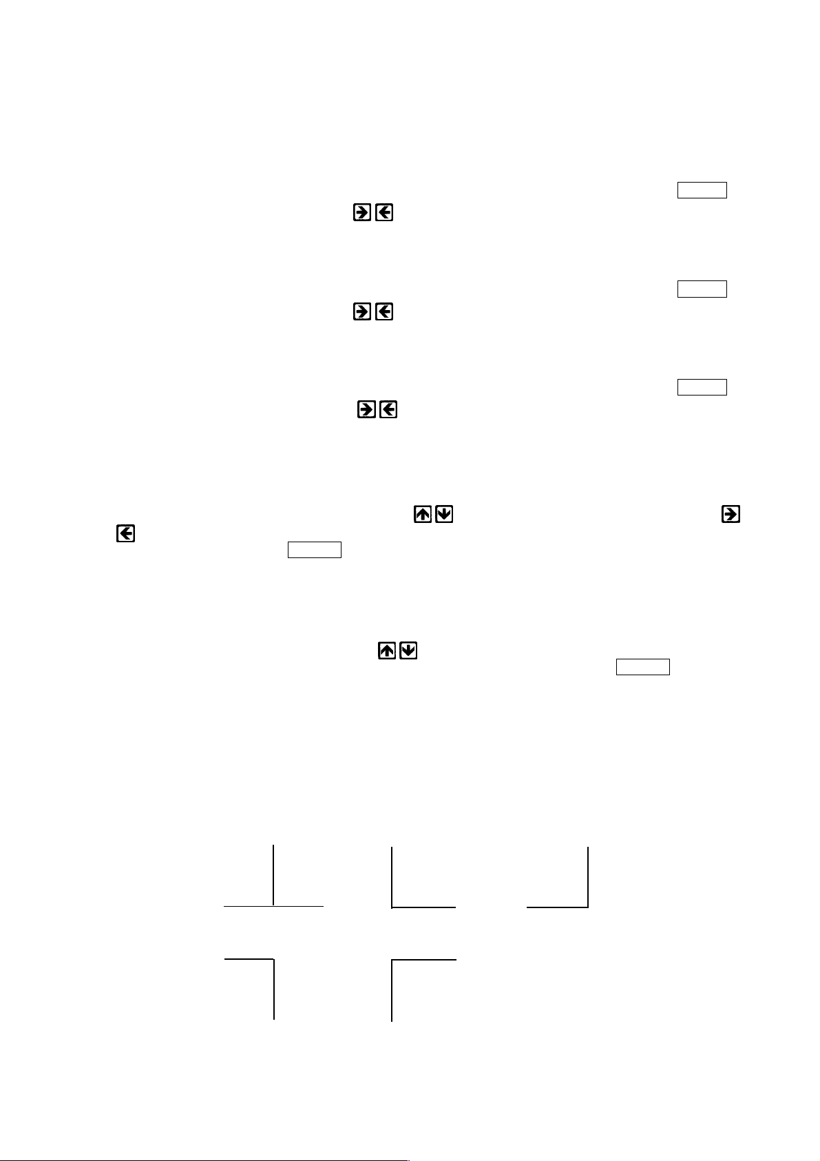
(2) Drawing for each tool
Change a drawing color at each time of tool change.
Applicable color are up to six and return to the beginning color beyond it.
Execute the setting by the color designation.
• marks are on at the side of setting has done. Change is decided by pressing the INPUT
key after selection by cursor key
.
(3) Cutting feed line
Designate the type of the cutting feed line.
• marks are on at the side of setting has done. Change is decided by pressing the INPUT
key after selection by cursor key
.
(4) Rapid traverse line
Designate the type of the rapid traverse line.
• marks are on at the side of setting has done. Change is decided by pressing the INPUT
key after selection by cursor key
.
(5) Color designation
Set a color to be changed when the drawing for each tool is effective.
Only this color designation change is available later.
Select a color designation by the cursor key
and designate a tool by the cursor key
.
Decide it by pressing the INPUT key after inputting a numeral from 0 to 7 according to the
instruction.
(6) Color of Drawing Point
Designate color of the first point of drawing.
Select color of drawing point by cursor
for setting.
Select the figure between 0 and 7 according to the explanation, and press INPUT for
deciding.
[Plane Setting]
(1) The drawing plane is designated. A plane is selectable from the following 5 options.
(0)
3
21
2
(1)
1
1
2
(2)
1
2
(3)
2
(4)
1
1 - 92
 Loading...