

Page 1

SEIKI - SEICOS
å10L/å16T/å18T/å21L
INSTRUCTION MANUAL
PROGRAMMING
42 Edition 1.01 NO-0000-1-0211-E-1-01
Hitachi Seiki Deutschland
Werkzeugmaschinen GmbH
Page 2

2
Page 3

INTRODUCTION
This manual explains about the programming system of SEICOS-Σ10L, Σ16T,Σ18T and Σ21L.
The manual contains explanation on all functions, however, there are certain functions that are not
applicable depending on the type of the machine used. On this matter, please refer to the
instruction manual of each machine model when you utilize these functions.
Items requiring attention when reading this manual.
(1) In this manual, those functions not specifically remarked “able” should be understood as
“unable”.
(2) The contents of this manual may be changed without notice to meet a future machine
improvement.
(3) In this manual, all the descriptions take G18 (Z-X) plane as the subject plane, unless otherwise
specifically mentioned. For cutting processes made on a plane other than G18, refer to “7.8
Lathe turning on other than the G18 plane”.
ΣΣ
Σ10L,
ΣΣ
The processing programs of Σ10L, Σ16T, Σ18T and Σ21L are nearly 100% compatible.
As exceptions, Σ21L does not have the following functions.
ΣΣ
Σ16T,
ΣΣ
[1] 2.4 Helical interpolation
[2] 2.5 Virtual axis interpolation
[3] 4.6 Automatic corner override
[4] 5.2 Inside arc cutting speed change
[5] 6.5 Floating reference point return
ΣΣ
Σ18T and
ΣΣ
ΣΣ
Σ21L
ΣΣ
Page 4

Page 5

CONTENTS
1. G CODE................................................................................................ 1 - 1
1.1 G Code System............................................................................................................. 1 - 1
1.2 List of G Code Groups................................................................................................... 1 - 3
1.3 List of G Codes .............................................................................................................1 - 4
2. INTERPOLATION FUNCTION............................................................. 2 - 1
2.1 Positioning (G00)........................................................................................................... 2 - 1
2.2 Linear Interpolation ........................................................................................................2 - 3
2.3 Circular Interpolation (G02, G03) ...................................................................................2 - 5
2.4 Helical Interpolation (G02, G03) .....................................................................................2 - 9
2.5 Virtual Axis Interpolation (G07)..................................................................................... 2 - 1 1
2.6 Cylindrical Interpolation (G271).................................................................................... 2 - 12
2.7 Polar Coordinate Interpolation (G120, G121)............................................................... 2 - 17
2.8 Angle Designated Linear Interpolation .........................................................................2 - 25
2.9 Skip Function (G31).....................................................................................................2 - 27
3. THREAD CUTTING .............................................................................. 3 - 1
3.1 Thread Cutting (G32).....................................................................................................3 - 1
3.2 Continuous Thread Cutting (G32) ................................................................................. 3 - 3
3.3 Multi-thread Cutting........................................................................................................3 - 4
3.4 Variable Lead Thread Cutting (G34) ..............................................................................3 - 5
4. FEED FUNCTION ................................................................................ 4 - 1
4.1 Feed Per Minute (G98) .................................................................................................. 4 - 1
4.2 Feed Per Revolution (G99)............................................................................................4 - 2
4.3 Dwell (G04) ...................................................................................................................4 - 3
4.4 Exact Stop (G09)...........................................................................................................4 - 4
4.5 Exact Stop Mode (G61) .................................................................................................4 - 5
4.6 Automatic Corner Override Mode (062).........................................................................4 - 6
4.7 T apping Mode (G63) ......................................................................................................4 - 8
4.8 Cutting Mode (G64) .......................................................................................................4 - 9
4.9 Multibuffer (G251) ........................................................................................................4 - 10
4.10 Acceleration/Deceleration Control ............................................................................... 4 - 11
5. SPEED CONTROL .............................................................................. 5 - 1
5.1 Feed Speed Command (F Data)................................................................................... 5 - 1
5.3 Scroll Cutting Speed Control (G128) ............................................................................. 5 - 4
5.4 Speed Control of Independent Axis ..............................................................................5 - 10
i
Page 6

6. REFERENCE POINT ........................................................................... 6 - 1
6.1 Automatic Reference Point Return (G28)......................................................................6 - 1
6.2 Reference Point Return Check (G27) ...........................................................................6 - 2
6.3 Return from Reference Point (G29) ..............................................................................6 - 3
6.4 2nd-4th Reference Point Return (G30)..........................................................................6 - 4
6.5 Floating Reference Point Return (G301) .......................................................................6 - 5
7. COORDINATE SYSTEM ..................................................................... 7 - 1
7.1 Tool Nose Coordinate System....................................................................................... 7 - 1
7.2 Plane Designation (G17, G18, G19) ..............................................................................7 - 4
7.3 Work Coordinate System Change (G50) ......................................................................7 - 6
7.4 Work Length Modification (G54/G55).............................................................................7 - 7
7.5 Machine Coordinate System Selection (G53) ............................................................... 7 - 8
7.6 Setting the Local Coordinate System (G59) ..................................................................7 - 9
7.7 Work Coordinate System Preset (G921) ....................................................................7 - 10
7.8 Lathe Turning Other than the G18 Plane (Z-X) ............................................................ 7 - 11
8. COORDINATE...................................................................................... 8 - 1
8.1 Diameter Designation and Radius Designation.............................................................8 - 1
8.2 Absolute/Incremental Programming (G90, G91) ...........................................................8 - 2
8.3 Inch/mm Input (G20, G21) .............................................................................................8 - 3
9. SPINDLE FUNCTIONS........................................................................ 9 - 1
9.1 Spindle Functions (Function S) ..................................................................................... 9 - 1
9.2 Constant Surface Speed Control (G96, G97)................................................................ 9 - 2
9.3 Maximum Spindle Speed Setting (G50) .........................................................................9 - 3
9.4 Spindle Speed V ariation Detection (G25/G26) ...............................................................9 - 4
10. TOOL FUNCTION............................................................................ 10 - 1
10.1 Tool Function (T Function)........................................................................................... 10 - 1
10.2 ATC Canned Cycle...................................................................................................... 10 - 5
10.3 Rotary Tool Offset Auto Conversion (G159) .............................................................. 10 - 11
10.4 ATC Type-E Offset Automatic Change........................................................................10 - 16
11. MISCELLANEOUS FUNCTION....................................................... 11 - 1
11.1 Miscellaneous Function (M Function) .......................................................................... 1 1 - 1
11.2 2nd Miscellaneous Function ........................................................................................ 1 1 - 3
12. COMPENSATION FUNCTION ........................................................ 12 - 1
12.1 Automatic Tool Nose Radius Compensation and Cutter Compensation.....................12 - 1
12.2 Automatic Tool Nose Radius Compensation...............................................................12 - 2
12.3 Groove Width Compensation (G150, G151, G152)...................................................12 - 15
ii
Page 7

12.4 Multiple Offsets.......................................................................................................... 12 - 18
12.5 Cutter Compensation (G38-G42) .............................................................................. 12 - 22
12.6 Detailed Description of Cutter Compensation ........................................................... 12 - 28
13. CONVERTING FUNCTION.............................................................. 13 - 1
13.1 Programmable Mirror Image (G501, G511) .................................................................13 - 1
13.2 Setting Mirror Image ....................................................................................................13 - 3
13.3 Chamfering, Corner R .................................................................................................13 - 5
13.4 Optional Angle Chamfering/Corner R (, C, R) ............................................................. 13 - 7
13.5 Three Dimensional Coordinate Conversion (G268, G269)........................................13 - 10
14. SINGLE TYPE FIXED CYCLE........................................................ 14 - 1
14.1 O.D./I.D. Cutting Cycle (G90) ......................................................................................14 - 1
14.2 Canned Cycle for Thread Cutting (G92)......................................................................14 - 2
14.3 End/side Cutting Cycle (G94)......................................................................................14 - 5
14.4 Cautions Concerning Single Type Fixed Cycle............................................................14 - 6
15. MULTIPLE REPETITIVE CYCLE................................................... 15 - 1
15.1 Rough Planing of Inside & Outside Diameter (G71)....................................................15 - 2
15.2 Rough Planing Cycle of End Side (G72) .....................................................................15 - 9
15.3 Planing Cycle of Close Loop (G73) ...........................................................................15 - 12
15.4 Finish Cycle (G70).....................................................................................................15 - 14
15.5 Edge Cutting Cycle (G74) ......................................................................................... 15 - 15
15.6 Outside Diameter Edge Cutting Cycle (G75) ............................................................15 - 17
15.7 Combined Type Thread Cutting Cycle (G76) ............................................................ 15 - 19
15.8 Cautions Relating to Combined Type Fixed Cycle .................................................... 15 - 24
15.9 Alarms Relevant to Combined T ype Fixes Cycle ...................................................... 15 - 27
16. CANNED CYCLE FOR DRILLING .................................................. 16 - 1
16.1 Canned Cycle for Drilling (G80-G89, G831, G841, G861) ........................................... 16 - 1
16.2 Direct Tapping Cycle (G842, G843)........................................................................... 16 - 16
17. DATA SETTING............................................................................... 17 - 1
17.1 Programmable Data Input (G10) ................................................................................. 17 - 1
17.2 Programmable Parameter Input ..................................................................................17 - 5
18. STROKE LIMIT ................................................................................ 18 - 1
18.1 Stored Stroke Limit 1 ...................................................................................................18 - 1
18.2 Stroke Limit 2 to 4 (G22, G23) .....................................................................................18 - 3
18.3 Stroke Limit Check before Move.................................................................................. 18 - 6
iii
Page 8

19. PROCESSING.................................................................................. 19 - 1
19.1 Rear Processing .........................................................................................................19 - 1
19.2 Polygon Turning (Polygon Turning Between S pindles) .............................................. 19 - 12
20. OPERATION ..................................................................................... 20 - 1
20.1 Program Resumption ..................................................................................................20 - 1
20.2 Return to Machining Interruption Point.........................................................................20 - 5
20.3 Sequence Number Comparison and Stop................................................................... 20 - 7
20.4 Manual Absolute ON/OFF............................................................................................20 - 8
20.5 Reset (Reset Associated with Automatic Operation) ................................................ 20 - 11
21. CUSTOM MACROS ........................................................................ 21 - 1
21.1 Program Call .............................................................................................................. 21 - 1
21.2 Multi-Call......................................................................................................................21 - 7
21.3 Argument Designation...............................................................................................21 - 12
21.4 Variables....................................................................................................................21 - 17
21.5 System V ariable ........................................................................................................21 - 20
21.6 Expression and Computation .................................................................................... 21 - 33
21.7 Control Command.....................................................................................................21 - 38
21.8 External Output Command........................................................................................21 - 41
22. COMPATIBILITY WITH SEICOS-LII/LIII......................................... 22 - 1
22.1 Drilling Fixes Cycle (G80-G89)....................................................................................22 - 2
23. MISCELLANEOUS .......................................................................... 23 - 1
23.1 Preread Stop Command .............................................................................................23 - 1
iv
Page 9
1.1 G Code System
Three kinds of G code systems including A, B, and C are available for selection. Any G code
systems are almost the same in their functions and programming methods except only part
of the G codes are different.
When S pecifying the position of each axis, however, there is a difference in the absolute and
incremental programming methods between the A system and non-A systems.
1.1.1 A system
Absolute programming and incremental programming use an axial address to specify an
axial position. When X, Y, Z, B, or C is used for the axial address, they assume absolute
programming, and when U, V, W, D, or H is used, they assume incremental programming.
The following table shows the relations between axial names and axial addresses.
1. G CODE
Axial Name
Absolute Incremental
X axis X U
Y axis Y V
Z axis Z W
A axis A
B axis B D
C axis C H
Axis A does not have the address of the incremental command. It is always specified by
absolute. However , only for commands G28, G30 and G301, absolute commands and
incremental commands of axis A can be switched over as follows.
(1) When address Q is present on the same block
• Q=0 → Absolute command
• Q≠0 → Incremental command
(2) When address Q is not present on the same block
• Parameter AINC=0 → Absolute command
• Parameter AINC=1 → Incremental command
(AINC means 3 bits of parameter number 3404.)
Axial Address
1 - 1
Page 10

1.1.2 B and C Systems
The following G codes are used to specify either absolute programming or incremental
programming.
G90 : Absolute programming
G91 : Incremental programming
These G codes are modal ones of Group 03.
(Note 1) The G code system A, B, and C are selected by the parameters GSB and GSC
(parameter No.3400.)
(Note 2) This command manual is described with the G codes of the A system unless
otherwise specified.
1 - 2
Page 11

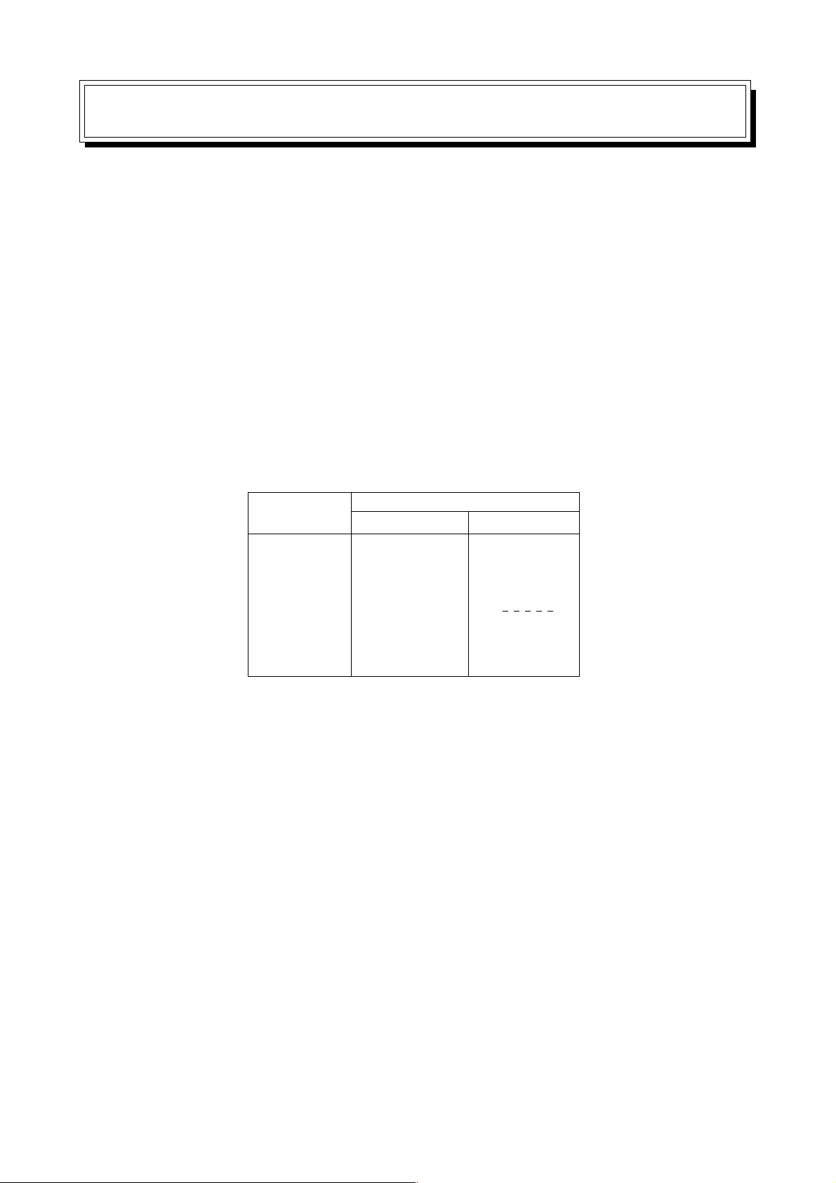
1.2 List of G Code Groups
Group Function Remarks
00 Non-modal
01 Positioning/linear interpolation/circular interpolation
02 Plane designation
03 (Absolute programming/incremental programming)
04 Stored stroke check
05 Feed per minute/feed per revolution
06 Inch/metric conversion
07 Cutter compensation
08 *2
09 Canned cycle for drilling
10 Initial point return/R-point return
11 *2
12 Work length modification
13 Cutting mode/exact stop mode/automatic corner override
mode
14 Macro modal call
15 Programmable mirror image
16 Groove width compensation
17 Constant surface speed control
18 Tool life management
19 *2
20 *2
21 *2
22 Polar coordinate interpolation
23 Spindle speed fluctuation detection
24 *2
25 Mirror image for double turrets *
26 *2
27 Automatic tool nose radius compensation/cutter
compensation enable/disable
28 *2
29 *2
30 *2
31 *2
(Notes) *2 Spare G code group for improvement of the functions.
1 - 3
Page 12
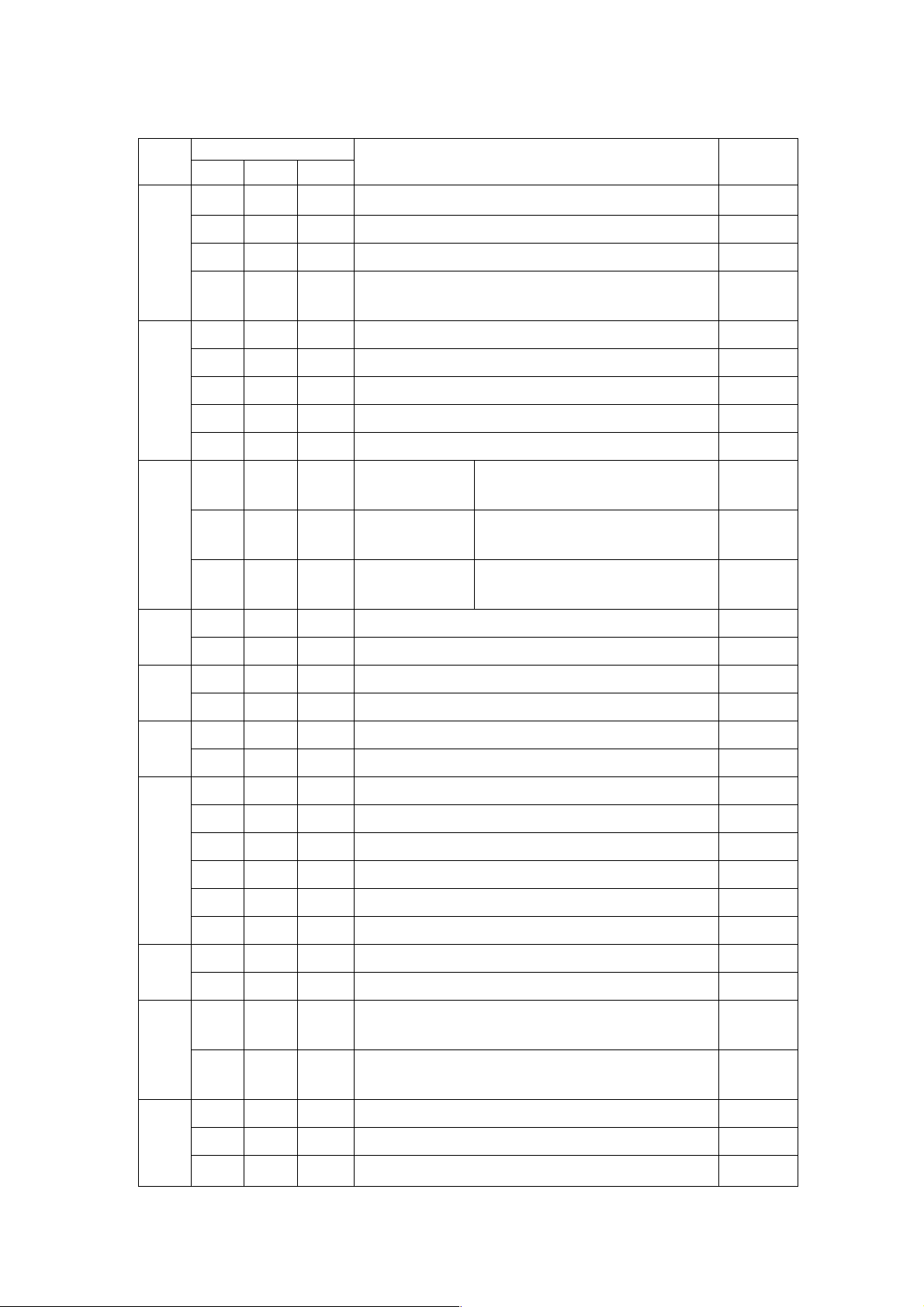
1.3 List of G Codes
Group
01 G00 G00 G00 Positioning
00 G04 G04 G04 Dwell
02 G17 G17 G17 Xp-Yp plane Xp: X axis or its
G code system
ABC
G01 G01 G01 Linear interpolation
G02 G02 G02 Circular interpolation/helical interpolation CW
G03 G03 G03 Circular interpolation/helical interpolation
CCW
G07 G07 G07 Virtual axis interpolation
G09 G09 G09 Exact stop
G10 G10 G10 Data setting
G11 G11 G11 Data setting mode cancel
designation parallel axis
G18 G18 G18 Zp-Xp plane Yp: Y axis or its
designation parallel axis
G19 G19 G19 Yp-Zp plane Zp: Z axis or its
designation parallel axis
Function Remarks
06 G20 G20 G70 Inch input
G21 G21 G71 Metric input
04 G22 G22 G22 Stored stroke check ON
G23 G23 G23 Stored stroke check OFF
23 G25 G25 G2 5 Spindle speed fluctuation detection OFF
G26 G26 G26 Spindle speed fluctuation detection ON
00 G27 G27 G27 Reference point return check
G28 G28 G2 8 Reference point return
G29 G29 G29 Return from reference point
G30 G30 G30 2nd, 3rd, 4th reference point return
G301 G301 G301 Floating reference point return
G31 G31 G31 Skip function
01 G32 G32 G3 2 Thread cutting
G34 G34 G34 Variable lead thread cutting
00 G38 G38 G38 Tool nose radius compensation/cutter
compensation vector hold
G39 G39 G39 Tool nose radius compensation/cutter
compensation corner arc
07 G40 G40 G40 Cutter compensation cancel
G41 041 G41 Cutter compensation to the left
G42 G42 G42 Cutter compensation to the right
1 - 4
Page 13

Group
01 G50 G92 G92 Coordinate system setting/spindle
12 G54 G54 G54 Work length modification 1
00 G59 G59 G59 Local coordinate system setting
13 G61 G61 G61 Exact stop mode
00 G65 G65 G65 Macro calling
14 G66 G66 G66 Macro modal call
00 G70 G70 G72 Finishing cycle
G code system
ABC
maximum speed setting
G52 G52 G52 Back face machining mode Back
G53 G53 G53 Machine coordinate system selection
G55 G55 G55 Work length modification 2 *1
G62 G62 G62 Automatic corner override mode
G63 G63 G63 Tapping mode
G64 G64 G64 Cutting mode
G67 G67 G67 Macro modal call cancel
Function Remarks
G71 G71 G73 O.D./I.D. roughing cycle
G72 G72 G74 End face roughing cycle
G73 G73 G75 Closed loop turning cycle
G74 G74 G76 End face cutting-off cycle
G75 G75 G77 O.D./I.D. cutting-off cycle
G76 G76 G78 Compound type thread cutting cycle
09 G80 G80 G80 Drilling cycle cancel
G81 G81 G81 Drilling cycle, spot drilling cycle
G82 G82 G82 Drilling cycle, counter boring cycle
G83 G83 G83 Peck drilling cycle
G831 G831 G831 Peck drilling cycle
G84 G84 G84 Tapping cycle
G841 G841 G841 Counter tapping cycle
G842 G842 G842 Direct tapping cycle *1
G843 G843 G843 Counter direct tapping cycle *1
G85 G85 G85 Boring cycle
G86 G86 G86 Boring cycle
G861 G861 G861 Fine boring cycle
G87 G87 G87 Back boring cycle
G88 G88 G88 73. Boring cycle
G89 G89 G89 74. Boring cycle
1 - 5
Page 14

Group
01 G9 0 G77 G20 O.D./I.D. turning cycle
17 G96 G96 G96 Constant surface speed control
05 G98 G94 G94 Feed per minute
03 G90 G90 Absolute programming
22 G120 G120 G120 Polar coordinate interpolation mode cancel
00 G128 G128 G128 Scroll cutting speed control
18 G130 G130 G130 Tool life management OFF
G code system
ABC
G92 G78 G21 Single type thread cutting cycle
G94 G79 G24 End face turning cycle
G196 G196 G196 Constant surface speed control (Back) Back
G97 G97 G97 Constant surface speed control cancel
G99 G95 G95 Feed per rotation
G91 G91 Incremental programming
G121 G121 G121 Polar coordinate interpolation mode
G131 G131 G131 Tool life management ON
Function Remarks
27 G140 G140 G140 Automatic tool nose compensation/cutter
compensation cancel mode
G143 G143 G143 Automatic tool nose compensation enable
mode
G144 G144 G144 Automatic tool nose radius compensation
enable mode (G144 = G143)
G145 G145 G145 Cutter compensation enable mode
00 G141 G141 G141 Automatic tool nose radius compensation
to the left
G142 G142 G142 Automatic tool nose radius compensation
to the right
16 G150 G150 G150 Groove width compensation cancel
G151 G151 G151 Groove width compensation for end face
G152 G152 G152 Groove width compensation for O.D./I.D.
00 G159 G159 G159 Automatic Conversion of Rotation A TC-C
Tool Offset
25 G170 G170 G170 Face machining mode Back
G171 G171 G171 Back face machining mode Back
00 G194 G194 G194 External measurement compensation
1 - 6
Page 15

Group
10 G198 G198 G198 Canned cycle for drilling initial point return
01 G212 G212 G212 Circular thread cutting CW *1
00 G251 G251 G251 Multibuffer
G code system
ABC
G199 G199 G199 Canned cycle for drilling R-point return
G213 G213 G213 Circular thread cutting CCW *1
G216 G216 G216 S pline interpolation *1
G222 G222 G222 Involute interpolation CW *1
G223 G223 G223 Involute interpolation CCW *1
G232 G232 G232 Exponential function interpolation CW *1
G233 G233 G233 Exponential function interpolation CCW *1
G261 G261 G261 S-designation for the spindle
G262 G262 G262 S-designation for the rotary tool
G263 G263 G263 S-designation for the subspindle Back
Function Remarks
G271 G271 G271 Cylindrical interpolation
15 G501 G501 G501 Resetting programmable mirror image
G511 G511 G511 Setting programmable mirror image
00 G921 G921 G921 Work coordinate system preset
(Note 1) *1 Reserve G code and not available for the moment.
(Note 2) The G code systems, A,B, are selected by the parameters GSB and GSC
(parameter No. 3400).
(Note 3) “Back” in the Remarks column indicates availability for the back machining
system.
1 - 7
Page 16

1 - 8
Page 17
2. INTERPOLA TION FUNCTION
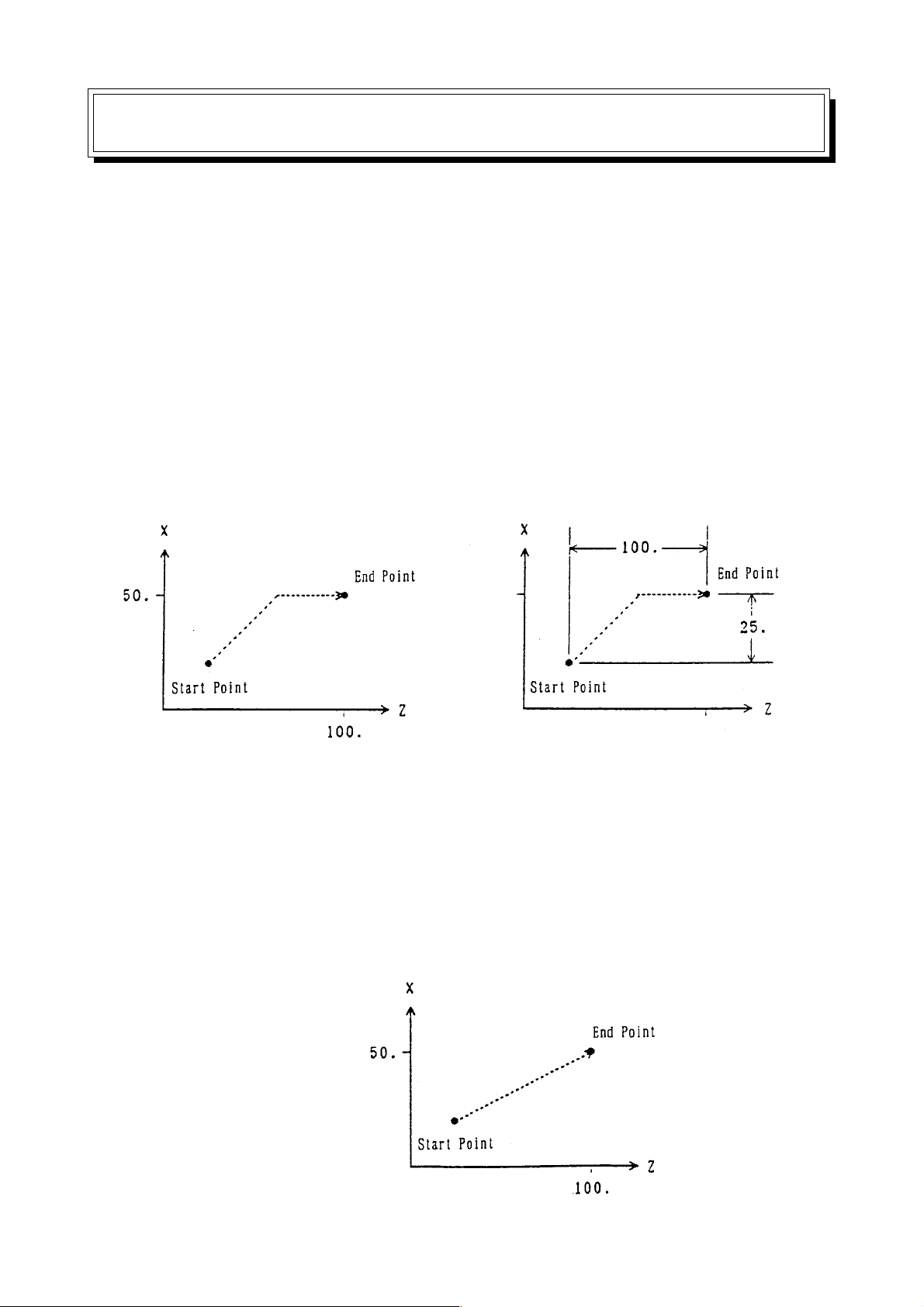
2.1 Positioning (G00)
Each axis moves to a program-specified position at an independent rapid traverse rate to
perform positioning.
2.1.1 Command Format
G01 X___ Y___ Z___ ...... F___ ;
2.1.2 Sample Program
(1) Absolute programming (2) Incremental programming
G00 X50, Z100, ; G00 X50, Z100, ;
2.1.3 Cautions
(1) The rapid traverse rate has been set independently for each axis.
(2) The tool path is non-linear . See to it that the tool does not interfere with the workpiece.
(3) Linear acceleration/deceleration is applied. Confirm imposition (an accumulated
amount due to servo delay is within tolerance) at the end of the block, and then,
proceed to the next block.
(4) The tool path can be made linear by altering the parameter.
G00 X50, Z100, ;
2 - 1
Page 18

When linear interpolation positioning has been selected, shifting takes place in the
speed which assures the shortest positioning time within the scope not exceeding
rapid traverse rate for each axis.
(5) You can set with the parameter whether the reset state is to be the G00 or G01 mode.
2.1.4 Associated Parameters
No.1401, #1= 0 Positioning system is non-linear type.
= 1 linear type (linear interpolation).
No.1401, #6= 0 Dry run disabled for rapid traverse command.
Dry run enabled for rapid traverse command.
No.3402, #0 = 0 Reset state is G00 mode.
= 1 Reset state is G01 mode.
No.1420 Rapid traverse rate for each axis.
No.1620 Time constant of rapid traverse linear acceleration/deceleration for each axis.
2 - 2
Page 19
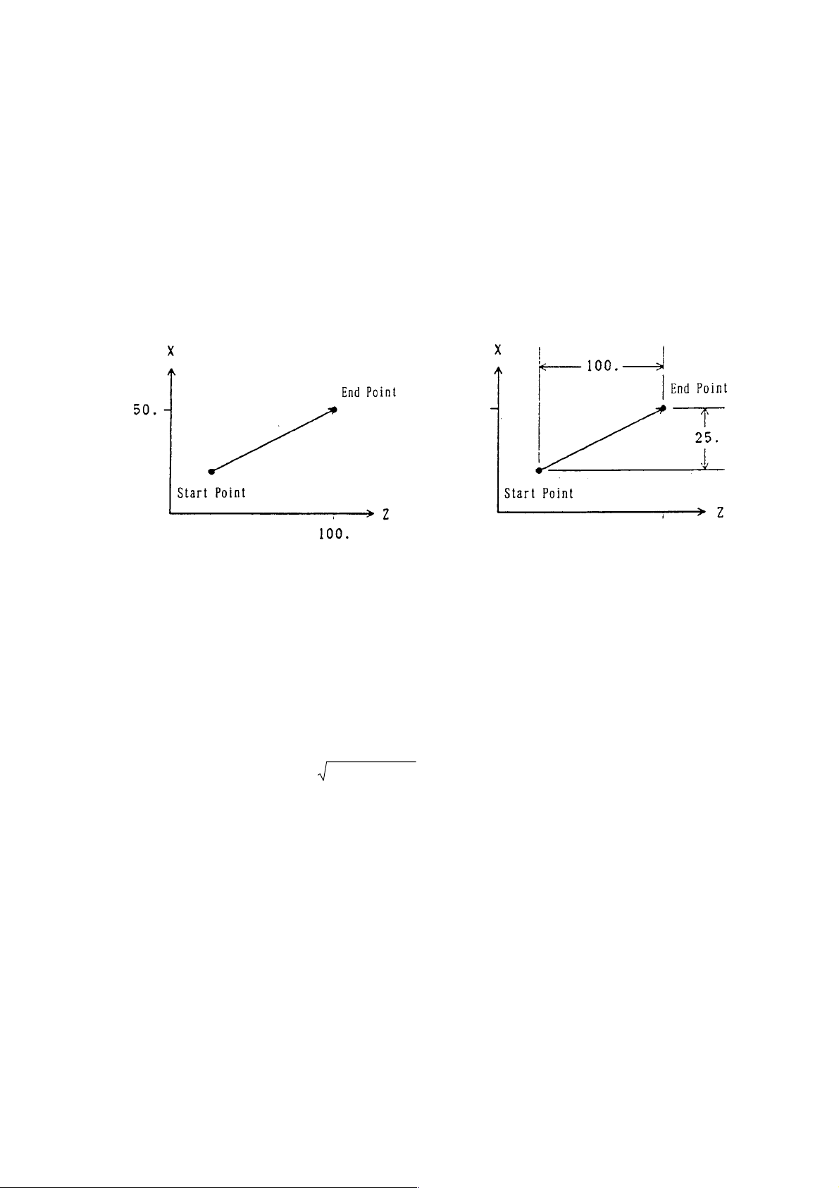
2.2 Linear Interpolation
The toolmvoes linearly to a program-specified position at the cutting feed rate specified with
an F code.
2.2.1 Command Format
2.2.2 Sample Program
(1) Absolute programming (2) Incremental programming
G01 X50. Z100. F200 ; G01 X50. W100. F200 ;
2.2.3 Cutting Feed Rate
The cutting feed rate specified with an F code is the speed at which the toolmoves linearly.
In this case, the cutting feed rate is a composite speed of all the specified axes; the cutting
feed rate of each axis is as follows.
G01 Ua Vb Wc Ff ;
X-axis cutting feed rate Fx = af/2L
Y-axis cutting feed rate Fy = bf/L
Z-axis cutting feed rate Fz = cf/L
where; L = (a/2)
(Note) When the rotary axis is specified in the identical block, linear interpolation is
performed taking it as a linear axis in the units of degree.
2+b2+c2
2 - 3
Page 20

2.2.4 Cautions
(1) An alarm results when no F code has been specified in the G01 block or before.
(2) Exponential type acceleration/deceleration is applied.
(3) Set with the parameter whether the reset state is to be the G00 or G01 mode.
2.2.5 Associated Parameters
No.3402, #0 = 0 The reset state is the G00 mode
= 1 The reset state is the G01 mode
No.1422 Maximum cutting feed speed (common to all axes)
No.1622 Time constant of cutting feed exponential type acceleration/deceleration
No.1623 FL speed of cutting feed exponential type acceleration/deceleration
2.2.6 Associated Alarms
No.102 F has not been specified in cutting feed. Or, F0 has been specified.
2 - 4
Page 21
2.3 Circular Interpolation (G02, G03)
The tool moves to a program-specified position along an arc within the plane selected with a
plane selection G code(G17, G18,G19) at the cutting feed rate specified with an F code.
2.3.1 Command Format
(1) Xp-Yp plane
G17
(2) Zp-Xp plane
G18
(3) Yp-Zp plane
G19
G02
G03 R_
G02
G03 R_
G02
G03 R_
Xp_ Yp_
Zp_ Xp_
Yp_ Zp_
I_ J_
K_ I_
J_ K_
F_ ;
F_ ;
F_ ;
where, Xp : X axis or its parallel axis
Yp : Y axis or its parallel axis
Zp : Z axis or its parallel axis
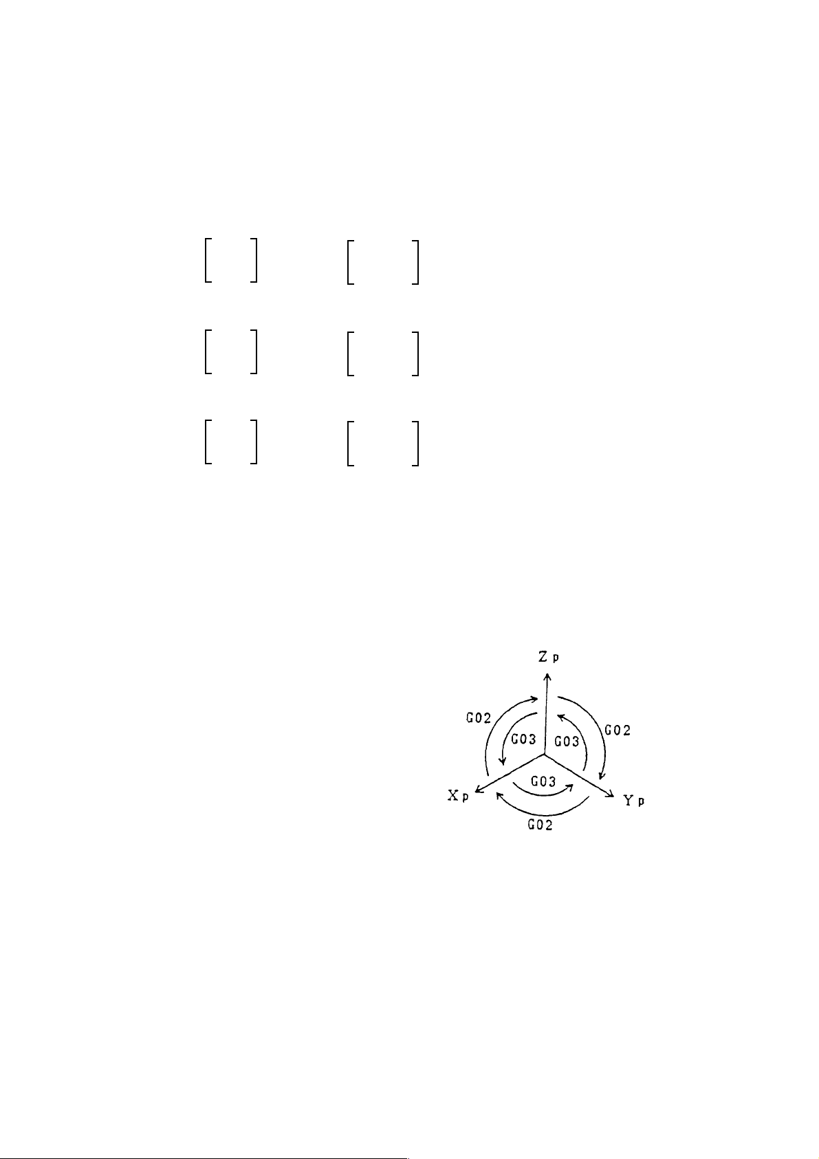
2.3.2 Arc Rotating Direction
G02 : Clockwise (CW)
G03 : Counterclockwise (CCW)
2 - 5
Page 22
2.3.3 Arc Plane
The arc plane is specified with G17, G18, or G19.
G17 : Xp-Y p plane
G18 : Zp-Xp plane
G19 : Y p-Zp plane
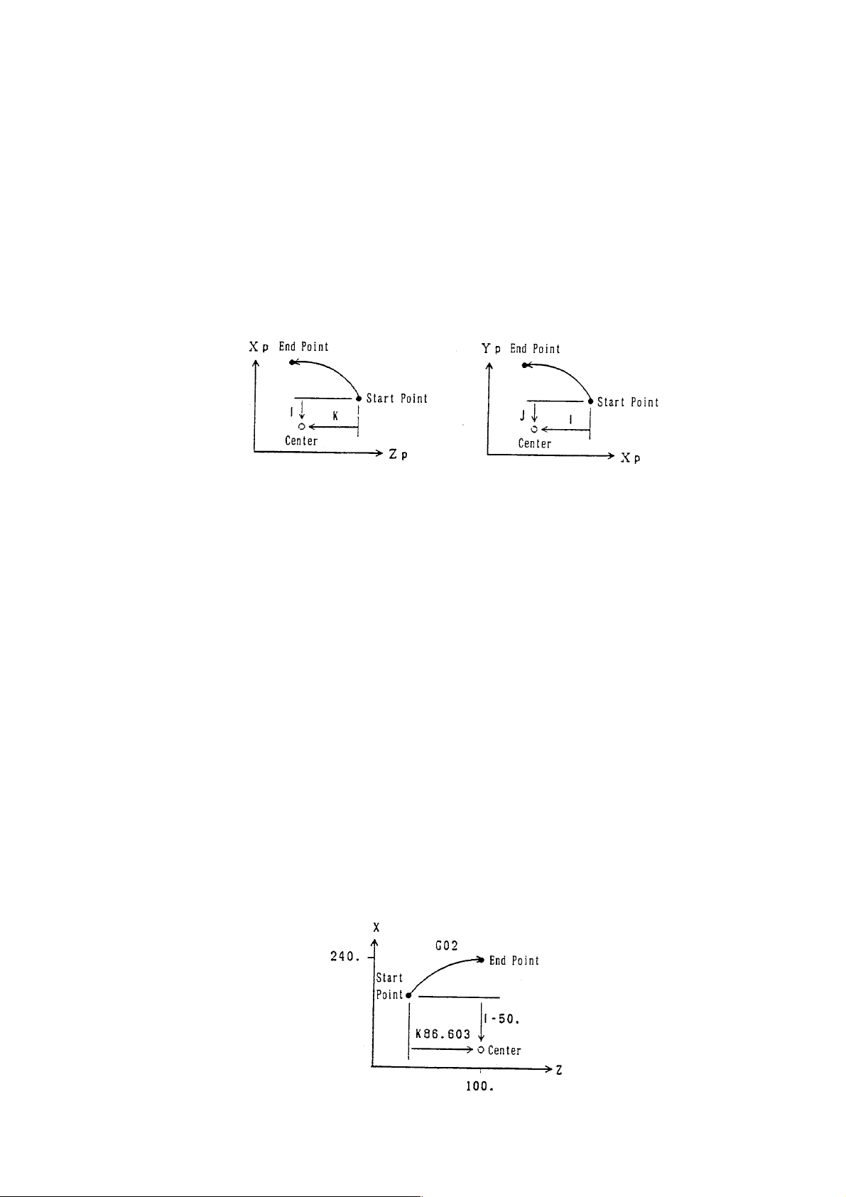
2.3.4 Arc Center
The arc center is specified with I, J, or K corresponding to Xp, Yp, and Zp, respectively. In
this case, I, j, and K are the vector components when viewing the arc center from its start
point.
(Note 1) Instead of using I, J, and K, you can use R to assign an arc radius.
(R assignment of arc radius) When applying R assignment to an arc of 180°
and above, specify an R in minus.
(Note 2) A full circle (360°) is not applicable in R assignment. Use I, J, and K for a full
circle.
When an arc close to 180° or to 360° is specified in R assignment, calculation
error may be produced, resulting in center deviation.
In this case, assign the center by using I, J, and K.
2.3.5 Cutting Feed Rate
The cutting feed rate specified with an F code is the speed at which the tool moves on the
arc.
2.3.6 Program Example
(1) Absolute Command Using I, J, and K:
G18 G00 X140. Z13.397 ;
G02 X240. Z100. I-50. K86.603 F200 ;
2 - 6
Page 23
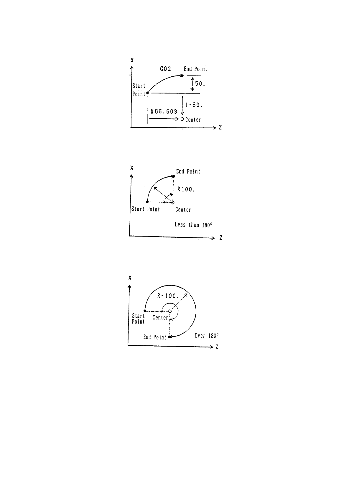
(2) Incremental Command Using I, J, and K:
G18 G02 U100. W86.603 I-50. K86.603 F200 ;
(3) An Arc of 180° or Less Using Radius R Assignment:
G18 G02 U200. W100. R100. ;
(4) An Arc of 180° or more Using Radius R Assignment:
G18 G02 U200. W100. R100. ;
2.3.7 Cautions
(1) An alarm results when no F code has been specified in the G02/G03 block or before.
(2) Exponential type acceleration/deceleration is applied.
(3) An alarm results if an arc radius = 0 is specified.
(4) I0, J0, and K0 are omissible.
2 - 7
Page 24

(5) When there is no end point on the arc, the tool moves linearly the rest after moving
along an arc if the end point error of circular interpolation is within the parameter set
value. Also, an alarm results if it is other than the p arameter set value.
(6) An alarm results if the axis not for the arc plane is specified.
(7) When R is specified in the same block as I, J, and K, R is given priority.
(8) When the canter of a circular arc is not calculated, alarm takes place.
2.3.8 Associated Parameters
No.1422 Maximum cutting feed speed (common to all axes)
No.1622 Time constant of cutting feed exponential type acceleration/deceleration
No.1623 FL speed of cutting feed exponential type acceleration/deceleration
No.3459 Arc radius error limit value
2.3.9 Associated Alarms
No.102 No F has been commanded in cutting feed. Or, F0 has been commanded.
No.131 The R value in arc radius R assignment is erroneous.
No.132 An arc for which difference in radius values between the start point and the
end point is larger than the parameter set value has been commanded.
(#001) No center command (I, J, K)
(#002) Center command (I, J, K) is 0.
(#003) Arc end point allowable error is too large.
(Note) When an option for helical interpolation is not added, specifying the axis for other
than the arc plane results in the alarm #191 (OPTION COMMAND).
2 - 8
Page 25
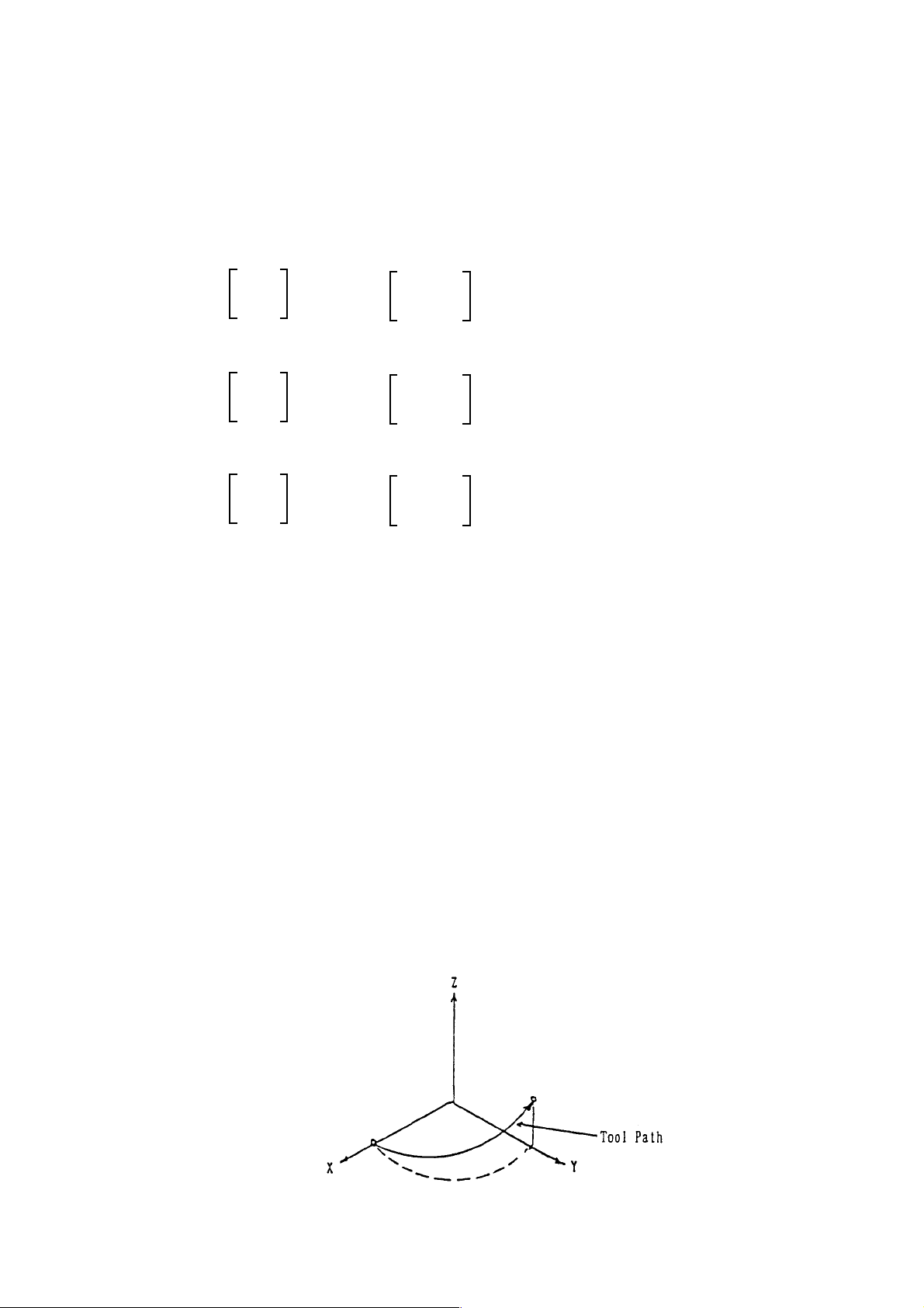
2.4 Helical Interpolation (G02, G03)
If an arc command and any one axis for other than arc are specified, helical interpolation is
enabled by control which performs linear interpolation synchronously with arc movement.
2.4.1 Command Format
(1) Xp-Yp plane
G17
(2) Zp-Xp plane
G18
(3) Yp-Zp plane
G19
G02
G03 R_
G02
G03 R_
G02
G03 R_
Xp_ Yp_
Zp_ Xp_
Yp_ Zp_
I_ J_
K_ I_
J_ K_
.... Not available with
a_ F_ ;
a_ F_ ;
a_ F_ ;
ΣΣ
Σ21L.
ΣΣ
where; Xp : X axis or its parallel axis
Yp : Y axis or its parallel axis
Zp : Z axis or its parallel axis
α : Any optional linear axis for other than circular interpolation (up to 2 axes)
F : Arc speed
2.4.2 Feed Speed
Feed speed command F in helical interpolation is equal to the speed in which a tool moves
on an arc.
Speed of the straight line axis = F × (length of the straight line axis/the arc length)
2.4.3 Sample Program
G17 G03 U-200. V100. R100. W50. F200 ;
2 - 9
Page 26

2.4.4 Cautions
(1) See to it that the linear axis speed does not exceed the maximum value.
(2) Cutter compensation is applied to circular interpolation.
(3) The axes for other than circular interpolation can be specified up to 2 axes.
Specifying 3 axes or more results in an alarm.
(4) The tool speed can be the composite speed of arc and linear speeds by parameter
setting.
2.4.5 Associated Parameters
2.4.6 Associated Alarms
No.149 In helical cutting, 3 or more linear axes have been commanded.
2 - 10
Page 27
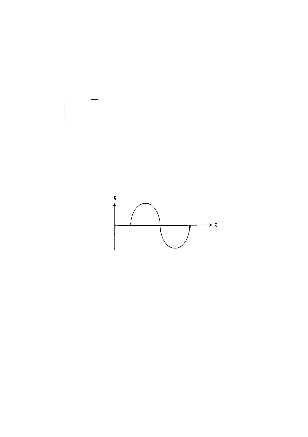
2.5 Virtual Axis Interpolation (G07)
When a virtual axis is assigned, axis shift does not take place.
In helical interpolation, by making one of circular command axes as a virtual axis, you can
perform SIN interpolation.
2.5.1 Command Format
G07 α 0 ; Sets the α axis as the virtual axis
The α axis is the virtual axis in this section
G07 α 1 ; Cancels the α axis as the virtual axis
where ; α : Any one axis
2.5.2 Sample Program
G07 Y0 ;
G17 G03 U0 V0 I-50. Z100. F200 ;
.... Not available with
ΣΣ
Σ21L.
ΣΣ
2.5.3 Cautions
(1) Virtual axis assignment is applicable only to 1 axis. If 2 or more axes should be
assigned, alarm takes place.
(2) When axial shift has been commanded for the axis assigned as a virtual axis, dwell
state equal to the shift time is produced.
(3) Command the virtual axis in incremental.
2.5.4 Associated Alarms
No.139 Two or more virtual axes are specified.
2 - 11
Page 28
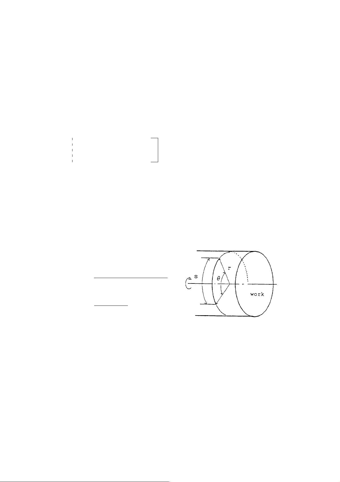
2.6 Cylindrical Interpolation (G271)
The stroke of the rotary axis internally specified in terms of angle is converted into the
circumferential distance by specifying the stroke of the linear axis and the angle of the rotary
axis with a program command. Since the circumferential distance can be regarded as the
stroke of the linear axis on the circumference, linear interpolation and circular interpolation
can be performed with other linear axes. Af ter interpolation, it is reconverted into the angle of
the rotary axis.
2.6.1 Command Format
G271 C Cylinder radius ; Cylindrical interpolation ON
Cylindrical interpolation mode
G271 C0 ; Cylindrical interpolation cancel
C denotes the rotary axis.
The move angle of the rotary axis is calculated back from the circumferential stroke.
For example, when you want to move 100.0 on the circumference of a cylinder whose
radixis is 50.0, the move angle of the rotary axis is obtained from the following expression.
r : Cylinder radius
θ : Move angle
s : Circumferential stroke
Move angle=
(Circumferenttial stroke)
(Cylinder radius)
360×100.0 =
=
2×
π×50.0
114.591
2 - 12
Page 29

2.6.2 Feed Rate
Feed rate command F in the cylindrical interpolation mode is the speed at which the tool
moves around the perimeter of a cylinder .
2.6.3 Circular Interpolation Axis
A linear as well as a rotating axis for which circular interpolation is performed are set in
parameters beforehand (S traight line axis: No.3426, Rot ary axis: No.3427).
The set range for both parameters, however, should be within 1~ no. of control axes and
the parameters should not be the same for both axis.
2.6.4 Circular Interpolation Plane
During the circular interpolation mode, a plane for which the rotating axis is set to 1st plane
axis and the straight line axis to 2nd plane axis is automatically selected.
2 - 13
Page 30
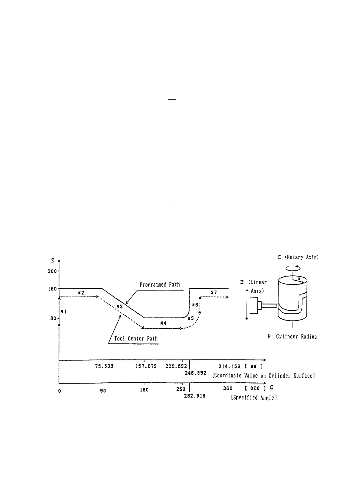
2.6.5 Sample Program (X Axis is Diameter Specification)
(C-Z plane selected with Parameter No. 3426/3427.)
T0100 ;
G98 G145 G40 G80 ;
G00 X120.0 Z-120.0 C0 ;
G145 ;
G271 C50.0 ; Cylindrical interpolation mode ON
N1 G42 G01 Z-40.0 F500 ; (Cylinder radius = 50.0)
G01 X100.0 F100 ;
N2 C90.0 F500 ;
N3 Z-100.0 C180.0 ;
N4 C260.0 ; In the cylindrical
N5 G03 Z-80.0 C282.918 R20.0 ; interpolation mode
N6 G01 Z-60.0 ;
N7 G02 W20.0 H22.918 R20.0 ;
N8 G01 C360.0 ;
N9 G40 G01 Z-120.0 ;
G271 C0 ; Cylindrical interpolation mode OFF
G00 Z50.0 C0 ;
Developed View of Cylinder Surface with Radius of 50.0
2 - 14
Page 31

2.6.6 Cautions
(1) Arc radius programming with I, J, or K is not allowed during the cylindrical interpolation
mode. Use radius designation on arc and specify it with the coordinate value on the
cylinder surface.
(2) During cylinder interpolation mode, the plane (plane selected by G17 - G19) before
entering the cylinder interpolation node will be canceled once, and then restored after
completion of the cylinder interpolation mode.
(3) The circular arc radius specification method (which of the addresses I, J, K to use)
when performing circular arc interpolation during the cylinder interpolation mode, will
be decided depending on which axis of the basic coordinate system the second axis
(straight line axis) of the cylinder interpolation plane corresponds to, as shown below.
• When the straight line axis is the X axis or parallel to it, Zp-Xp plane will be taken,
specified by K, I.
• When the straight line axis is the Y axis or parallel to it, Xp-Yp plane will be taken,
specified by I, J.
• When the straight line axis is the Z axis or parallel to it, Yp-Zp plane will be taken,
specified by J, K.
Also, the circular arc radius can be specified by the R command.
(4) (G271 Cxx)
(5) An alarm results if 2 or more rotary axes are specified with the G271 command.
(6) Cylindrical interpolation is not available for the following functions:
• Machining break point return
• Manual intervention by manual absolute ON
(7) An alarm results if the following commands are given during the cylindrical
interpolation mode.
G28, G30, G53 Machine coordinate system
Thhttxx; (T command), G54, G50 Work coordinate system
G70-G76, G81-G89, G831-G861, G861
G90-94 Various canned cycles
G31, G121, G232 Others
(8) In the cylindrical interpolation mode, the angle of the rotary axis is converted into the
distance on the circumference, and after interpolation, it is converted the other way
around. When this is done, a slight conversion error occurs.
(9) Due to the above conversion error, a circular interpolation alarm may occur if circular
interpolation with a small circular arc radius is performed during the cylindrical
interpolation mode. When using, care should be taken. Also, a cutter compensation
alarm may occur at the time of cutter compensation due to the above reason.
(10) An alarm results if G271 Cxx; (C ≠ 0) (cylindrical interpolation mode ON) is specified
during the cylindrical interpolation mode.
(1 1) The remaining stroke indicates the value at the time of moving on the perimeter of the
cylinder.
2 - 15
Page 32

2.6.7 Related Parameters
No.3426 Axis number (1 - No of control axes) of the straight line axis for performing
circular interpolation
No.3427 Axis number (1 - No of control axes) of the rotating axis for performing circular
interpolation
2.6.8 Related Alarm
No.126 An error exists in cylindrical interpolation command.
(#001) No rotary axis command exists.
(#002) No independent command exists.
(#003) Modal G code is not in correct state.
No.127 An erroneous command has been give while in cylindrical interpolation mode.
(#001) An erroneous G code has been commanded.
(#003) Rotary axis shifting command has been given in G00 mode.
(#004) Cylindrical interpolation has been commanded again while in cylindrical
interpolation mode.
No.189 (G271) Parameter setting is erroneous.
• Parameters No. 3426/No.3427 do not fall within 1 ~ no. of control axes. Or,
No.3426 and No.3427 are equal.
• The straight line axis set in Parameter No.3427 does not correspond to or
parallel to any of the basic three axes (X, Y, Z).
2 - 16
Page 33

2.7 Polar Coordinate Interpolation (G120, G121)
Polar coordinate interpolation is a function to provide contour control by converting the
command programmed in the orthogonal coordinate system into the movement of the linear
axis (tool movement) and that of the rotary axis (workpiece rotation).
<Orthogonal Coordinate System> <Polar Coordinate System>
The relationship between (X1, C1) and (X1’, C1’) is as follows.
2
X1’ = X
1
+ C
2
1
C1’ = tan-1 (C1/X1)
2.7.1 G Codes
G121 : Polar coordinate interpolation mode
G120 : Polar coordinate interpolation mode cancel
2.7.2 Command Format
G121 ; Turns polar coordinate interpolation mode ON
Performs polar coordinate interpolation.
G120 ; Cancels polar coordinate interpolation mode.
2.7.3 Polar Coordinate Interpolation Axes
A straight line axis as well as a rotating axis for the polar coordinate interpolation are set in
the parameters beforehand (S traight line axis: No.3418, Rot ating axis: No.3419).
The set range for both parameters should be within 1 ~ no. of control axes and the
parameters should not be the same for both axis.
2.7.4 Polar Coordinate Interpolation Plane
When G121 is specified, the polar coordinate interpolation mode is put in effect, and the
plane (polar coordinate interpolation plane) is selected, which assumes the origin of the
work coordinate system as that of the coordinate system, the linear axis as the first
plane axis, and virtual axis (rotary axis) orthogonal to the linear axis as the second plane
2 - 17
Page 34

axis. Polar coordinate interpolation is performed on this plane. For the position specified
by G121, the angle will be taken as 0 and polar coordinate interpolation started, regardless
of the actual position. Therefore, create the program by taking the work coordinate value
of the rotating axis as 0 when G121 has been specified.
2.7.5 Program Command
(1) The program command in the polar coordinate interpolation mode is given in terms of
the orthogonal coordinate value of the polar coordinate interpolation plane.
The rotary axis address is used for the command address of the 2nd plane axis.
However, the programmable unit is not degrees; the same unit as that for the 1st
plane axis, linear axis (mm or inch). The 2nd plane axis assumes the same
designation as the rotary axis; it is neither diameter designation nor radius designation.
(2) During the polar coordinate interpolation mode, linear interpolation (G01) and circular
interpolation (G02, G03) can be specified. Both absolute programming and
incremental programming are allowed.
(3) When performing circular interpolation on the polar coordinate interpolation plane, the
circular arc specifying-method (which one of I, J, and K is to be used as the address)
is determined as follows depending on to which axis of the basic coordinate system
the 1st plane axis (linear axis) corresponds (parameter setting: No.1011).
• When the linear axis is either X axis or its parallel axis, the Xp-Yp plane is
assumed, and I/J is used to specify the circular arc radius.
• When the linear axis is either Y axis or its p arallel axis, the Yp-Zp plane is assumed,
and J/K is used to specify the circular arc radius.
• When the linear axis is either Z axis or its parallel axis, the Zp-Xp plane is assumed,
and K/I is used to specify the circular arc radius.
It is also possible to specify the circular arc radius with an R command.
(4) Cutter compensation can be applied to the program command. Polar coordinate
interpolation is performed for the profile after cutter compensation.
However, specify G121 and G120 in the cutter compensation cancel mode (G40).
(5) For feed rate, specify the shift speed of the tool in the polar coordinate interpolation
plane (orthogonal coordinate system) by F.
Since this is normally specified by feed per minute (G98), the units of F will be mm/
min, inch/min.
2 - 18
Page 35

2.7.6 Sample Program (X Axis [Diameter Assigned]: Linear Axis/C Axis[Radius
Assigned]: Rotary Axis)
G00 X130.0 C0 ; Positioning to start position
G145 ; Tool Diameter Compensation Effective mode
G121 ; Polar coordinate interpolation started.
N1 G42 G01 X80.0 F100 ;
N2 C40.0 ;
N3 G03 X60.0 C50.0 R10.0 ;
N4 G01 X-60.0 ; Profile program,
N5 C-15.0 ; Program with orthogonal coordinate
N6 G03 X-50.0 C-20.0 I5.0 J0 ; values on the X-C’ plane
N7 G01 X80.0 ;
N8 C0 ;
N9 G40 X130.0 ;
G120 Polar coordinate interpolation cancelled.
2 - 19
Page 36

2.7.7 Speed Clamping of the Rotating Axis
The maximum cutting feed speed for the polar coordinate interpolation can be set in the
parameter . (Parameter No.3464)
When any speed above this level is specified while in polar coordinate interpolation, it is
clamped to this speed. With the set value being 0, clamping is performed to the ordinary
maximum cutting feed speed (Parameter 1422) even while in polar coordinate
interpolation.
Further, in polar coordinate interpolation, as a shape having been programmed in the
orthogonal coordinate system are converted into movement of the straight line and the
rotating axes, rotating axis speed is increased in movement around the work center (origin
of the coordinate system), even exceeding the limit speed of Machine.
In the above case, the allowable speed of the rotating axis can be set in the parameter as
follows:
Allowable speed of rotating axis = Max. cutting feed speed (Parameter No. 3404) x
Allowable ratio (Parameter No.3420)
When the speed component of the rotating axis exceeds the allowable speed while in
polar coordinate interpolation, override shown below is automatically applied (Automatic
override):
Allowable speed of rotating axis
Override =
Speed component
× 100(%)
When the speed component of the rotating axis still exceeds the allowable speed even
with override being applied, feed speed is clamped so that the speed component of the
rotating axis does not exceed the maximum cutting feed speed. (Automatic speed clamp)
2.7.8 Rapid Traverse (G00) Operation
You can issue the G00 command during the polar coordinate interpolation mode.
However, only the start point and the end point will be converted to the positions of the
polar coordinate system for the G00 block.
There will be no conversion during the path from the start point to the end point.
Example: In the G121 mode, if the following command is issued:
G00 X100. C50.0 ;
The path will be the same as specified in the following command in the G120 mode:
G01 X141. 421 C45.0 ;
In the shift of the rotating axis by G00, close rotation (shift within +/-180 degrees) will be
performed and the processing time will be reduced.
2 - 20
Page 37

2.7.9 Special Specification A for Polar Coordinate Interpolation (Optional)
Through parameter setting, machining by a program of the X-Y coordinate system is made
available in the same manner with the machining center.
In G121 mode, the following conversion processes will be performed immediately after the
program is read in.
• X axis commands are processed as radius commands.
(X axis command is doubled)
• Y axis commands are converted to C axis commands. (Y → C, V → H)
(Note 1) Since the above conversion processes are performed on the basis of axis
name, the parameters must be set with the straight line axis as the X axis and
the rotating axis C axis that are subject to the polar coordinate interpolation.
(Note 2) Although X axis commands are possible with radius values, the coordinate
indication will follow the convention of the mechanical specification. (usually
diameter values)
(Note 3) Evan if the special specification A for polar coordinate interpolation is employed,
either the standard of special specification can be selected with the parameters.
2 - 21
Page 38

2.7.10 Cautions
(1) G120 and G120 should be specified in an independent block.
(2) Before specifying G121, the work coordinate system where the center of the rotary
axis serves as the origin of the coordinate system must be set. During the G121
mode, the coordinate system must not be altered.
(3) The plane(selected by G17, G18, or G19) prior to G121 is cancelled once by G121 and
restored by G120.
(4) The following G codes can be specified in the G121 mode:
G00, G01, G02, G03, G04, G09, G40, G41, G42, G65, G66, G67, G98, G99, G140,
G143, G144, G145
(5) For the axis move command outside the plane of the G121 mode, the axis moves
regardless of polar coordinate interpolation.
(6) The display of the “remaining stroke” in the G121 mode represents that in the polar
coordinate plane (orthogonal coordinates).
For G00 block, however, the unit for the ordinary case is applied.
(7) The following functions are not available for the blocks which are in the G121 mode:
Program restart, Machining break point return, Manual intervention by manual absolute
ON
(8) On completion of polar coordinate interpolation (G120), the work coordinate of the
rotating axis can be rounded at 360° through parameter setting. (0° coordinate
value < 360°)
(9) When the work coordinate value of straight line axis during G121 command is
negative for the first shift block, only the end point will be converted to the polar
coordinate system position. There will be no conversion during the shift. (Same as
the straight line type G00 in the G121 mode.)
From the next shift block, polar coordinate conversion will be performed for the shift
path. For the first, shift block, only G00 and G01 can be specified; G02 and G03
cannot be specified.
(10) Through parameter setting, you can specify G codes (G120/G121) for polar coordinate
interpolation by using G126/G127.
In specification with G126/G127, they are converted into standard G codes (G120/
G121) when an NC program is read into the buffer .
Therefore, command values and alarms are displayed in the standard G codes.
<
=
2 - 22
Page 39

2.7.1 1 Associated Parameters
No.3404, #4= 0 Work coordinates of rotating axis is not rounded on completion of
polar coordinate interpolation.
= 1 Work coordinates of rotating axis is rounded at 360° completion of
polar coordinate interpolation.
No.3404, #6= 0 Y-axis command in the polar coordinate interpolation is moved as Y-
axis command.
= 1 Y-axis command in the is moved by being replaced by C-axis
command.
No.3404, #7= 0 X-axis command in polar coordinate interpolation mode follows
machine specifications.
= 1 X-axis command in polar is taken as radius assignment.
No.3409, #0= 0 G codes for polar coordinate interpolation are G120/G121 (standard)
= 1 G126/G127
No.3410, #1= 0 Neither automatic override nor automatic speed clamp is performed
while in polar coordinate interpolation mode.
= 1 Automatic override and automatic speed clamp are performed while in
polar coordinate interpolation mode.
No.3418 Axis number of the linear axis for which polar coordinate interpolation is
performed
No.3419 Axis number of the rotary axis for which polar coordinate interpolation is
performed
No.3420 Axis number of the linear axis for which polar coordinate interpolation is
performed.
No.3464 Maximum cutting feed speed while in polar coordinate interpolation.
2 - 23
Page 40

2.7.12 Associated Alarms
No.1 13 An error exists in the polar coordinate interpolation command.
(#001) G120/G121 commands is not independent type.
(#002) When G120/G121 is specified, cutter compensation has not been cancelled.
(#003) When the work coordinate value of the linear axis is in minus on specification
of G121, a command other than G00/G01 has been specified in the first shift
block.
No.1 14 An erroneous command has been specified while in the polar coordinate
interpolation mode.
(#001) A G code not useable has been specified.
(#002) A T code has been specified.
No.189 (G121) An error exist s in parameter setting.
• Parameters No.3418/No.3419 are not within 1 ~ no. of control axes, or
No.3418 is equal to No.3419.
• The linear axis set in Parameter No.3418 is none of the basic three axes
(X/Y/Z), or not parallel to any of them.
2 - 24
Page 41

2.8 Angle Designated Linear Interpolation
By commanding an angle (A) formed between X or Z axis shifted and +Z axis, you can
perform angle designated linear interpolation.
2.8.1 Command Format
G01 X___ A___ ;
G01 Z___ A___ ;
2.8.2 Angle A
(1) Scope of angle A
<
-360.000 A 360.000 (deg)
(2) Angle A code
Plus ..........Counterclockwise angle from +Z axis
Minus ........Clockwise angle from +Z axis
<
=
=
2.8.3 Program Example
G18 G01 U20. A60. ;
W20. ;
W10. A-30. ;
30°
2 - 25
Page 42

2.8.4 Cautions
(1) When A is used as an axis name, this function is made invalid.
Address A indicates A axis, not an angle.
(2) Angle designated linear interpolation on other planes (G17/G19) is available.
As this angle A, an angle formed by the horizontal axis of the coordinate system in
plus direction (G17:+X, G19:+Y) is commanded.
(3) When the shift direction of the commanded axis and the shift direction after calculation
are opposite, alarm takes place.
G01 W100. A100. ;
<<Available A Range for Commanding in +Z Direction Command>>
2.8.5 Associated Parameters
2.8.6 Associated Alarms
No.177 An error exists in the command of angle designate linear interpolation.
(#001) Angle A value is out of the range.
(#002) An angle in opposite shift direction has been commanded.
2 - 26
Page 43

2.9 Skip Function (G31)
Linear interpolation is performed by a G31 command. If an external skip signal is input
during linear interpolation, the program proceeds to the next block, stopping the axes and
discarding the remaining stroke.
2.9.1 Command Format
G31 X___ Y___ Z___ ....... F___ ;
2.9.2 Sample Program
N1 G98 G31 W50. F100 ;
N2 G01 U50. W25. ;
2.9.3 Cautions
(1) G31 cannot be specified while in the corner R compensation/tool system
compensation mode.
(2) When the block next to the G31 command has been given by incremental
programming, the next block functions in the incremental manner from the
positioninterrupted by the skip signal.
(3) The G31 command is effective only in the block where it is specified.
(4) Position where skip has been input (work coordinates) can be read by the macro
system variable.
2.9.4 Associated Parameters
No.6200, #7= 0 Automatic acceleration/deceleration is made invalid to G31 skip
command.
= 1 Automatic acceleration/deceleration is made valid to G31 skip
command.
2.9.5 Associated Alarms
2 - 27
Page 44

2 - 28
Page 45

3. THREAD CUTTING
3.1 Thread Cutting (G32)
With a G32 command, straight threads and tapered threads can be cut ata equal leads
synchronously with the pulses from the spindle encoder.
3.1.1 Command Format
(1) Straight thread cutting at equal leads
G32 α___ F___ (E___) ;
where; α : Any one axis
F (E) : Thread lead
(2) Tapered thread cutting at equal leads
G32 α___ β___ F___ (E___) ;
where; α, β : Any one axis
F (E) : Thread lead
(3) Thread cutting at equal leads by specifying the number of threads per inch
G32 α___ β___ E___ ;
where; α, β : Any one axis
E : No. of threads per inch
(Note) Use a parameter to set whether to specify the thread lead with an E code or the
number of threads per inch.
3.1.2 Sample Program
(1) Straight thread cutting at equal leads
G32 W-10. F2.0 ;
(2) Tapered thread cutting at equal leads
G32 U-10. W-20. F2.0 ;
(3) Straight thread cutting at equal leads by specifying the number of threads per inch
G32 W-50. E5.0 ;
(5 threads per inch; Thread lead = 5.08 mm)
3 - 1
Page 46

3.1.3 The Range of Thread Lead will be as Follows
(a) Metric programming
F35 : 0.00001 ~ 999.99999 (mm/rev)
F26 : 0.000001 ~ 99.999999(mm/rev)
(b) Inch programming
F26 : 0.000001 ~ 99.999999 (inch/rev)
F17 : 0.0000001 ~ 9.9999999 (inch/rev)
(Note) The number of significant digits for F and E is the same.
3.1.4 Cautions
(a) The feed hold function is disabled during thread cutting. If the FEED HOLD button is
pressed during thread cutting, the program stops at the end point of the block next to
the non-thread cutting block.
(b) Cutting feed override and spindle override is disabled and fixed at 100 % during thread
cutting.
(c) An alarm results if 3 axes or more are specified in the same block.
(d) Give the thread lead (F or E) in the first G32 mode.
(e) If E is given during the G32 mode, it remains effective until F is given. Also, if F and E
are given in the same block, F is given priority.
3.1.5 Associated Parameters
No.1401, #5= 0 Dry run disabled during thread cutting and tapping.
= 1 Dry run enabled during thread cutting and tapping.
No.3401, #4= 0 F/E code for thread cutting in inch input is F26.
= 1 F/E code for thread cutting in inch input is F17.
No.3401, #5= 0 F/E code for thread cutting in mm input is F35.
= 1 F/E code for thread cutting in mm input is F26.
No.3403, #7= 0 E code for thread cutting is equal to the number of threads per inch of
the thread lead.
3 - 2
Page 47

3.1.6 Associated Alarms
No.103 An error exists in the thread cutting command.
(#001) Commands have been given for 3 or more axes.
3.2 Continuous Thread Cutting (G32)
Continuous thread cutting is enabled by continuously specifying the thread cutting command
blocks.
3.2.1 Sample Program
N1 G32 U-10.0 W-20.0 F3.0 ;
N2 W-10.0 ;
N3 U10.0 W20.0 ;
3.2.2 Cautions
(a) Stop at single block is not possible during thread cutting.
3 - 3
Page 48

3.3 Multi-thread Cutting
If you specify Q together with the thread cutting command (G32, G34, G76, G92), you can
shift the thread cutting start angle by the specified shift Q.
If you execute thread cutting of the same shape after changing the Q value, you can execute
multi-thread cutting.
3.3.1 Command Format
G32 α___ β___ Q___ F___ ;
Where, alpha, beta: Any one axis
: Thread lead in the direction of the longitudinal axis
F
Q : Thread cutting start shift angle (0 to 360 degrees)
Other thread cutting commands are similar to the one described above.
3.3.2 Example of Program
G32 W-30.0 F2.0 Q180 ;
Shift by 180 degrees with respect to the reference point.
3.3.3 Precautions
(1) Either 1 degree or 0.001 can be selected as the unit for shift angle Q, by parameter
setting.
(2) If you have selected 1 degree as the unit for Q, specify Q without the decimal point.
• Q1 → Indicates 1 degree
• Q1.0 → Indicates 1000 degrees
(3) If you have selected 0.001 as the unit for Q, specify Q with the decimal point.
• Q1 → Indicates 0.001 degrees
• Q1.0 → Indicates 1.0 degree
(4) When you use a macro variable in Q, select 0.001 degree as the unit for Q. Example:
Q#510
(5) Even if you select 0.001 in the unit for Q, since the feedback pulse from the spindle
encoder is normally 4096 pulse / rev . , the actual resolution will become 360 degrees/
4096 = 0.088 degree.
(6) The Q specification for continuous thread cutting will be effective only in the thread
cutting start block.
(7) If the Q specification exceeds the 0 to 360 degree range, alarm will occur .
3.3.4 Related Parameters
No.3404, #2= 0 Unit for the shift angle Q is 1 degree.
= 1 Unit for the shift angle Q is 0.001 degree.
3.3.5 Related Alarm
No.103 An error exists in the thread cutting command.
(#001) Commands have been given for 3 or more axes.
(#002) Q command value has exceeded the set range.
3 - 4
Page 49

3.4 Variable Lead Thread Cutting (G34)
Variable lead threads can be cut by specifying an incremental or decremental amount per
revolution of thread in the G34 command block.
3.4.1 Command Format
G34 α___ β___ F___ K___ ;
where; α, β : Any one axis
F : Thread lead in the longitudinal direction at thread cutting start time
K : Incremental amount (decremental amount for a nagative value) per
revolution
The programmable range of K is as follows.
Metric system : ±0.001 to ±99999.999 (mm/rev)
Inch system : ±0.0001 to ±9999.9999 (inch/rev)
3.4.2 Sample Program
Straight thread cutting at variable leads
(Thread lead at start time: 2.0 mm, Incremental amount per rev. : 0.5mm)
G34 W-10.0 F2.0 K0.5 ;
In variable lead thread cutting, feed speed is changed constantly as above so that lead is
changed for every rotation.
The lead for 1st rotation in thread cutting becomes “F± (K/2)” and the lead for 2nd rotation
on is increased/decreased by K for every rotation.
3.4.3 Cautions
(1) A G34 command with K omitted results in thread cutting at equal leads (G32
command).
3 - 5
Page 50

3 - 6
Page 51
4. FEED FUNCTION
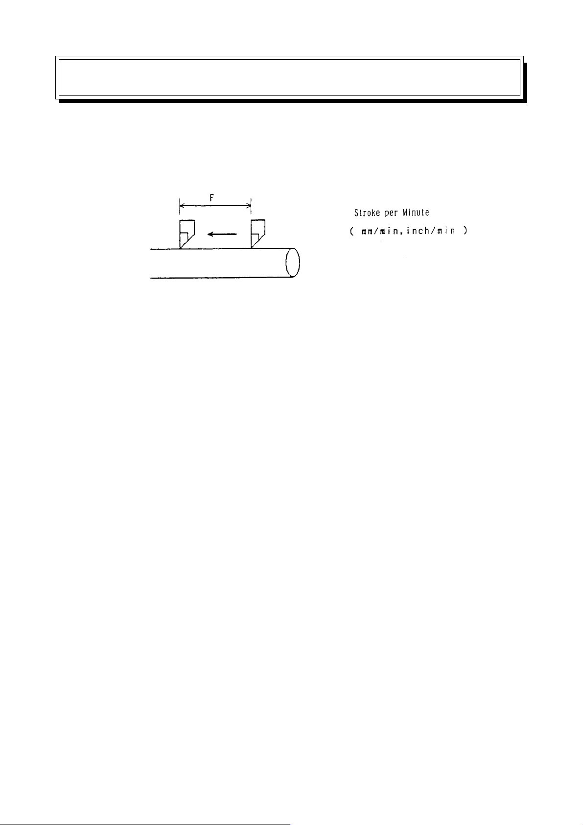
4.1 Feed Per Minute (G98)
Until G99 is specified after G98, specify the stroke per minute (mm/min., inch/min.) with a
numerical value following F as to the cutting feed rate.
4.1.1 Command Format
G98 ;
4.1.2 Sample Program
G98 F100 ; The cutting feed rate is 100 mm per minute.
4.1.3 The F Code Programmable Range is as Follows
(1) Metric system
F60 : 1~ 999999 (mm/min)
F61 : 0.1~ 999999.9 (mm/min)
(2) Inch system
F51 : 0.1~ 99999.9 (inch/min)
F52 : 0.01~ 99999.99 (inch/min)
4.1.4 Cautions
(1) One of F60, F61, F51, and F52 is selected by. parameter setting.
(2) When F61 is specified without a decimal point in the metric system, the least input
increment of 1 mm/min. or 0.1 mm/min. can be selected by parameter setting.
(3) In case of thread cutting (G33), feed per revolution is assumed temporarily even
during the G98 mode.
4.1.5 Associated Parameters
No.3400, #1= 0 The unit without a decimal point for metric input F61 is 1mm/min.
= 1 The unit without a decimal point for metric input F61 is 0.1mm/min.
No.3401, #2= 0 Feed per minute for inch input is F51.
= 1 Feed per minute for inch input is F52.
No.3401, #3= 0 Feed per minute for metric input is F60.
= 1 Feed per minute for metric input is F61.
4.1.6 Associated Alarms
No.102 F has not been specified in cutting feed. Or, F0 has been specified.
4 - 1
Page 52

4.2 Feed Per Revolution (G99)
Until G98 is specified after G99, specify the stroke per minute (mm/rev., inch/rev.) with a
numerical value following F as to the cutting feed rate.
4.2.1 Command Format
G99 ;
4.2.2 Sample Program
G99 F12 ; The cutting feed rate is 1.2 mm per revolution.
4.2.3 The F Code Programmable Range is as Follows
(1) Metric system
F32 : 0.01 ~ 999.99 (mm/rev)
F33 : 0.001 ~ 999.999 (mm/rev)
(2) Inch system
F23 : 0.001 ~ 99.999 (inch/rev)
F24 : 0.0001 ~ 99.9999 (inch/rev)
4.2.4 Cautions
(1) One of F32, F33, F23, and F24 is selected by parameter setting.
4.2.5 Associated Parameters
No.3401, #0 = 0 Feed per rotation for inch input is F23.
= 1 Feed per rotation for inch input is F24.
No.3401, #1= 0 Feed per rotation for metric input is F32.
= 1 Feed per rotation for metric input is F33.
4.2.6 Associated Alarms
No.102 F has not been specified in cutting feed. Or, F0 has been specified.
4 - 2
Page 53

4.3 Dwell (G04)
A G04 command can delay migration of operation to the next block.
When specifying by time: The command causes the machine to wait for the
When specifying by revolutions: The command causes the machine to wait while the
4.3.1 Command Format
(1) When specifying by time
G98 G04 P___ ;
P: Dwell time (0.001 to 99999.999 sec.)
(2) When specifying by revolutions
G99 G04 P___ ;
P: Dwell revolutions (0.001 to 99999.999 rev .)
(Note) X or U can be used instead of P.
4.3.2 Sample Program
specified time.
spindle rotates the number of revolutions specified.
G98 G04 P2000 ; Dwell time 2 seconds
G04 X2.0 ; Dwell time 2 seconds
4.3.3 Cautions
(1) It is normally set to dwell specified by time (per-minute dwell).
Through parameter setting, however , dwell specified by rot ation (per-rot ation dwell)
can be set in the per-rotation feed mode.
4.3.4 Associated Parameters
No.3400, #5= 0 G04 always specfies by time
1 G04 follows G94 or G95
4 - 3
Page 54

4.4 Exact Stop (G09)
If a G09 command is specified in the same block as a move block, it decelerates and stops
the machine upon completion of one block, and after confirming that the machine position is
within the range in which a command position was specified, executes the next block.
4.4.1 Command Format
G09 .......... ;
4.4.2 Sample Program
N1 G09 G01 W50.0 F2.0 ;
N2 G01 U-50.0 ;
4.4.3 Associated Parameters
No.1801, #4= 0 Imposition width for cutting feed is Parameter No.1826 (Common to
rapid traverse)
= 1 Imposition width for cutting feed is Parameter No.1827 (Common to
rapid traverse)
No.1826 Imposition width of each axis
No.1827 Imposition width of each axis for cutting feed
4 - 4
Page 55

4.5 Exact Stop Mode (G61)
Until G62, G63, or G64 is specified after G61 was specified, this function decelerates and
stops the machine, confirms that the machine position is within the specified range, and
then, proceeds to the next block.
4.5.1 Command Format
G61 ;
4.5.2 Sample Program
N1 G61 G01 W-100. F1.0 ;
N2 U50. ;
N3 W-100. ;
The corner has an edge when the G61 mode is
effective.
The corner is rounded when the G61 is ineffective.
4.5.3 Switching Into M Code
Through setting a parameter, you can specify Exact Stop mode by using M21 command
instead of using G61 command.
M21, as it is replaced by G61 inside NC for execution, is not output in Machine side. Also,
with M21 command, G62 to G64 modes are cancelled.
4.5.4 Associated Parameters
No.1801, #4 = 0 Imposition width for cutting feed is Parameter No.1826 (Common to
rapid traverse)
= 1 Imposition width for cutting feed is Parameter No.1827 (Common to
rapid traverse)
No.3409, #1 ON/OFF command system for Exact Stop mode is:
= 0 G61 (ON) / G64 (OFF)
= 1 G61 or M21 (ON) / G64 or M22 (OFF)
No.1826 Imposition width of each axis
No.1827 Imposition width of each axis for cutting feed
4 - 5
Page 56

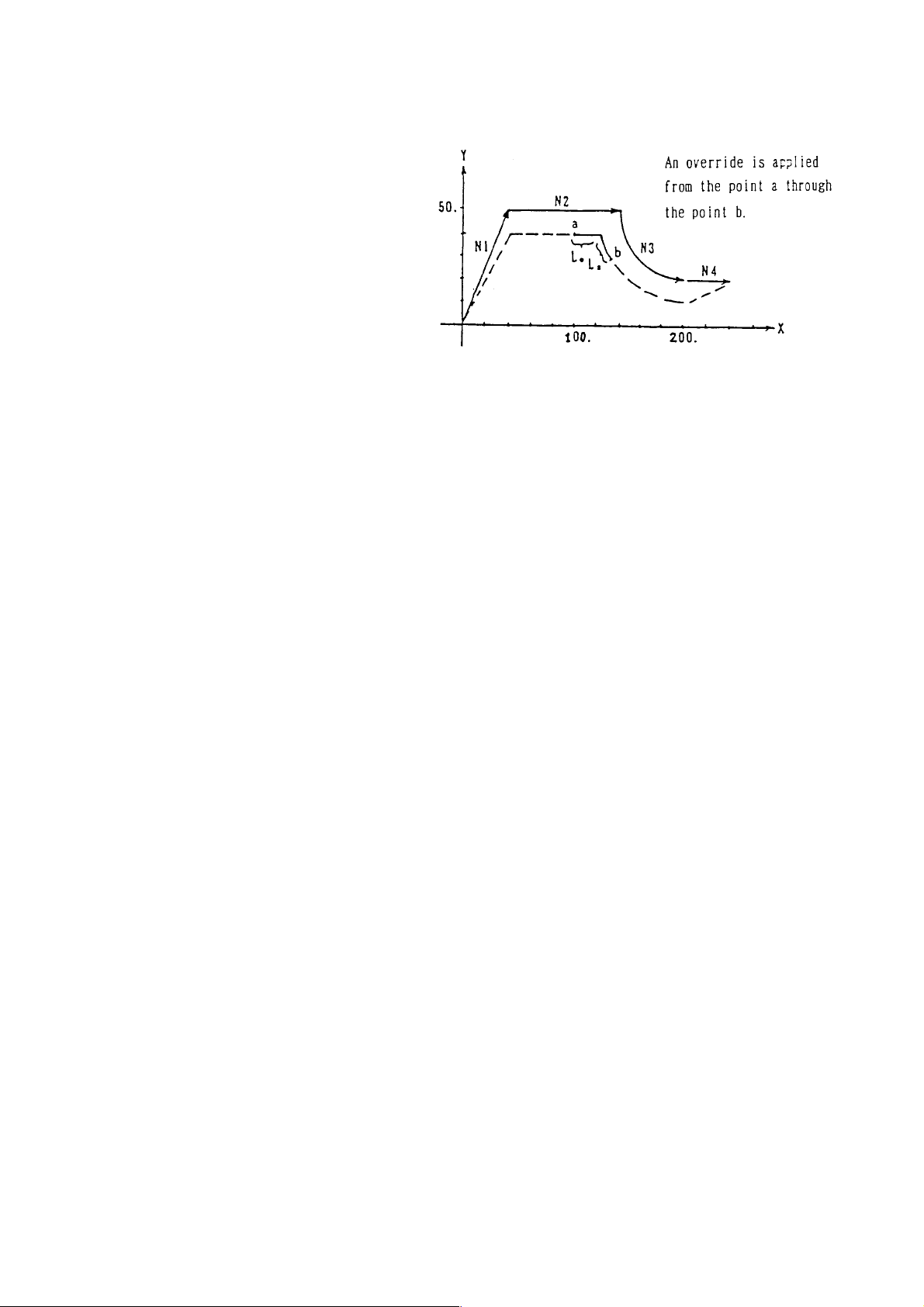
4.6 Automatic Corner Override Mode (062)
When cutter compensation is applied, since the tool center path is located inside the
program-specified path in the inner corner and inner arc area and a cutting load increases,
an override is applied automatically to the cutting feed ate to reduce the cutting load.
Once G62 is specified, it remains effective until G61, G63, or G64 is specified.
4.6.1 Command Format
G62 ;
4.6.2 Override Conditions
When the following conditions are met with respect to the blocks which are located before
and after the corner in the cutter compensation mode, an override is applied to cutting feed
automatically.
(a ) When the G code of Group 01 is G1, G02, or G03.
(b ) When an offset amount is not 0 in the cutter compensation offset mode.
(c ) When an offset is inside at the corner
(d ) When there is an axis in the offset plane.
(e ) When the G41 or G42 is not contained.
( f ) When an inner corner angle is smaller than a parameter set value. (θ)
(g ) When a corner start distance and a corner end distance are other than 0 and internal.
(Le, Ls)
.... Not available with
ΣΣ
Σ21L
ΣΣ
4.6.3 Override Amount
<
1 Automatic corner override 100 (%)
=
An actual cutting feed rate is as follows.
F × Automatic corner override × Cutting feed rate override
where; θ : Inner criterion angle
Le : Start distance
Ls : End distance
An override is applied to cutting feed
from the point a through the point b.
<
=
4 - 6
Page 57
4.6.4 Sample Program
N1 G62 G42 G00 U40. V50. ;
N2 G01 U100. F200 ;
N3 G03 U60. V-30. R30. ;
N4 G64 G40 G00 U40. ;
4.6.5 Cautions
(1) When a block not shifting has been specified between two blocks subject to automatic
corner override, tool diameter compensation is supplied while automatic corner
override is not.
4.6.6 Associated Parameters
No.1711 Inner criterion angle of automatic corner override (θ : deg.)
No.1712 Override of automatic corner override (%)
No.1713 Start distance (Le) of automatic corner override
No.1714 End distance (Ls) of automatic corner override
4 - 7
Page 58

4.7 Tapping Mode (G63)
The control state of the NC unit is as follows until G61, G62, or G64 is specified after G63 is
specified.
(1) Cutting feed rate override fixed at 100 %
(2) Spindle override fixed at 100 %
(3) Single block disabled
(4) Dry run disabled
(5) Feed hold disabled
(6) Decelerated stop disabled at the joint of the blocks (imposition check disabled)
(7) Tapping mode signal output
The G63 mode is effective until G61, G62, or G64 is specified.
4.7.1 Command Format
G63 ;
4.7.2 Sample Program
N1 G63 G01 X10. F200 ;
N2 Z0 ;
N3 X20. ;
N4 Z-5. ; Tapping mode effective blocks.
N5 X30. ;
N6 Z-10. ;
N7 G64 X40. ;
4.7.3 Cautions
(1) By parameter setting, you can invalidate dry run disabled.
4.7.4 Associated Parameters
No.1401, #5= 0 Enables dry run during thread cutting and tapping.
= 1 Disables dry run during thread cutting and tapping.
4 - 8
Page 59

4.8 Cutting Mode (G64)
Until G61, G62, or G63 is specified after G64 was specified, the next block is executed
continuously without decelerating to a stop between the blocks.
The G64 mode is effective until G61, G62, or G63 is specified.
When cutting is performed in the G64 mode, the corner may be rounded at the time of
cutting feed.
4.8.1 Command Format
4.8.2 Sample Program
N1 G64 G01 X10. F200 ;
N2 Z0 ;
N3 X20. ;
N4 Z-5. ; Cutting mode effective blocks
N5 X30. ;
N6 Z-10. ;
N7 G61 X40. ;
4.8.3 Switching Into M Code
Through setting a parameter , you can specify Cutting mode by using M22 command
instead of using G64 command.
M22, as it is replaced by G64 inside NC for execution, is not output in Machine side. Also,
with M22 command, G61 to G63 modes are cancelled.
4.8.4 Associated Parameters
No.3409, #1 ON/OFF command system for Exact Stop mode is:
= 0 G61 (ON) / G64 (OFF)
= 1 G61 or M21 (ON) / G64 or M22 (OFF)
4.8.5 Cautions
(1) G64 is set in the reset state.
(2) A G00 command decelerates the machine to a stop regardless of the G64 mode.
4 - 9
Page 60

4.9 Multibuffer (G251)
During automatic operation, the number of blocks to be preread is as follows.
(1) During the automatic tool nose radius compensation enable mode (G143) → 4 blocks
(2) During cutter compensation (G41/G42 in the G145 mode) → Max. 4 blocks
(3) Others → 1 block
A multibuffer command prereads up to 12 blocks.
This function makes it possible to reduce a stop time between the blocks when executing
the program having very small continuous blocks.
4.9.1 Command Format
G251 P0 ; or G251 ; Multibuffer mode ON
G251 P1 ; Multibuffer mode ON
4.9.2 Sample Program
G251 ; Multibuffer mode ON
Prereads up to 12 blocks in this portion.
G251 P1 ; Multibuffer mode OFF
4.9.3 Cautions
(1) The macro statement is not included in the number of preread blocks.
(2) Specify the G251 command in an independent block.
(3) When the very small blocks are executed continuously, there will be no preread
blocks, making an execution time shorter than the processing time of one block.
(4) The blocks may not be preread even in the multibuffer mode ON state, depending on
the commands.
(Example) G10, G20, G21, G22, G23
G28, G30, G31, G53
M00, M01, M02, M30
Coordinate system setting by a T command
(5) The reset state can be turned to the multibuffer mode ON state by parameter setting.
4.9.4 Associated Parameters
No.3402, #6= 0 Multibuffer mode OFF at reset time
= 1 Multibuffer mode ON at reset time
4.9.5 Associated Alarms
No.130 There is an erroneous command in the block.
(#001) G251 is not an independent command.
4 - 10
Page 61

4.10 Acceleration/Deceleration Control
4.10.1 Automatic Acceleration/Deceleration
Acceleration/deceleration are automatically applied at the start and the end of shifting so
that the machine system is protected from shock.
Acceleration/deceleration include the following types:
[Linear type [Exponential type
acceleration/deceleration] acceleration/deceleration]
[Bell type
acceleration/deceleration]
(1) Acceleration/deceleration types for standard setting are as follows:
1) Rapid traverse........................................... Linear acceleration/deceleration
2) Cutting feed (G01, G02, G03, G32) ........... Exponential type acceleration/
3) Manual continuous feed (JOG feed)..........Exponential type acceleration/
4.10.2 Other Acceleration/Deceleration (Optional)
(1) Rapid Traverse Bell Type Acceleration/Deceleration
Rapid traverse bell type acceleration/deceleration, through application of smooth
acceleration/deceleration to rapid traverse speed, can reduce mechanical shock due
to change in acceleration.
Compared with linear acceleration/deceleration, this enables setting of smaller time
constant, thus shortening time required for acceleration/deceleration.
(2) Linear Acceleration/Deceleration Following Cutting Feed Interpolation
Compared with the exponential type acceleration/deceleration, the linear acceleration/
deceleration following cutting feed interpolation reduces delay to a command to 1/2,
when given the same time constant, thus reducing time required for acceleration/
deceleration.
deceleration
deceleration
4 - 11
Page 62

Further, in the arc interpolation especially in high speed cutting, the actual tool p ath
subject to acceleration/deceleration has an error to the arc in its radius direction. This
error,. also, is reduced compared with that in the exponential type acceleration/
decelation.
(3) Bell T ype Acceleration/Deceleration Following Cutting Feed Interpolation
Bell type acceleration/deceleration following cutting feed interpolation is a function to
reduce shock given to the mechanical system by smoothing acceleration and
deceleration.
4.10.3 Associated Parameters
No.1610, #0/#1 Acceleration/Deceleration Available for Cutting Feed
(Including feed by dry run) :
Parameter No.1610
#1 #0
0 0 Exponential type acceleration/deceleration
0 1 Linear acceleration/deceleration following interpolation
1 0 Bell type acceleration/deceleration following interpolation
No.1610, #4= 0 Acceleration/deceleration for manual continuous feed (JOG feed) is by
exponential type acceleration/deceleration.
= 1 Acceleration/deceleration for manual continuous feed (JOG feed) is by
the same way as that of cutting feed.
No.6200, #7= 0 Automatic acceleration/deceleration of skip function (G31) is made
invalid.
= 1 Automatic acceleration/deceleration of skip function (G31) is made
valid.
No.1620 Time constant of linear acceleration/deceleration of rapid traverse for each
axis or time constant of rapid traverse bell type acceleration/deceleration T1.
No.1621 Time constant of linear acceleration/deceleration of rapid traverse for each
axis T2.
No.1622 Time constant of cutting feed exponential type acceleration/deceleration for
each axis, time constant of bell type acceleration/deceleration following cutting
feed interpolation, or time constant of linear acceleration/deceleration following
cutting feed interpolation.
No.1623 FL speed of exponential type acceleration/deceleration of cutting feed for each
axis.
Acceleration/Deceleration
4 - 12
Page 63

No.1624 Time constant of exponential type acceleration/deceleration of manual
continuous feed for each axis, time constant of bell type acceleration/
deceleration following interpolation, or time constant of linear acceleration/
deceleration following interpolation.
No.1625 FL speed of exponential type acceleration/deceleration of manual continuous
feed for each axis.
No.1626 Time constant of exponential type acceleration/deceleration of thread cutting
cycle for each axis.
No.1627 FL speed of exponential type acceleration/deceleration of thread cutting cycle
for each axis.
4 - 13
Page 64

4 - 14
Page 65

5. SPEED CONTROL
5.1 Feed Speed Command (F Data)
5.1.1 Modal In Per-Minute Feed and Per-rotation Feed
Feed rate “F”, once commanded, remains valid (modal) until the next command is given.
However , as “F” role is tot ally different between per-minute feed and per-rotation feed, it is
hardly of any use even if “F” is held modal in per-minute feed and per-rotation feed.
Oppositely, it can even cause danger.
For example, it can be dangerous if, after “F” having been commanded in per-minute feed,
axis shift is performed in per-rotation feed without commanding “F”.
N1 G98 G01 Z__ F2000 ; Speed is 2000mm/min
N2 G99 Z__ ; Speed is 20.00mm/rev
Modal “F”, therefore should be treated as follows:
Per-minute feed and per-rotation feed (incl. thread cutting) are held modal independently.
In other words, NC holds two “F” data including ones for per-minute feed and the other for
per-rotation feed. Depending on the feed mode for execution, the “F” to be used is
determined.
They are explained in details as follows:
The number of effective digits below a decimal point for “F” are 0 for per-minute feed/ 2 for
per-rotation feed/ 5 for thread cutting. And, “F” being made valid in that block is expressed
in [ ].
(Per-Minute Feed) (Per-Rotation Feed)
On Supply of Power 0 0.00
N1 G99 F1.23 ; 0 [1.23]
N2 ——— ; 0 [1.23]
N3 G98 F1000 ; [1000] 1.23
N4 ——— ; [1000] 1.23
N5 G32 F2.34567 ; 1000 [2.34567]
N6 ——— ; 1000 [2.34567]
N7 G99 ; 1000 [2.34]
N8 ——— ; 1000 [2.34]
N9 G98 ; [1000] 2.34
N10 —— ; [1000] 2.34
N1 1 G32 ; 1000 [2.34567]
5 - 1
Page 66

Also, when the feed per minute F is specified, the feed per revolution F can be made 0 by
parameter setting (No. 3401, #7=1) ; conversely, when the feed per revolution F is
specified, the feed per minute F can be made 0.
In this case, for the previous example, the feed per revolution F = 0 in N3 and the feed per
minute F = 0 in N5, therefore, the effective F in N9, N10, N11 will become 0.
When the inch input/mm input is changed by using the G code (G20/G21), inch/mm
conversion will be performed for modal data “F” also.
1000mm/min ←→ 39.3inch/min
5.1.2 F Command for Rotating Axis by Inch Input
The shift (deg) of rotating axis (C) is converted to inch and used.
[Example 1] G98 G01 U10.0 W20.0 H30.0 F20.0 ;
30 (deg) will be treated as 30 (inch).
Interpolation, distance (L) is:
L = (10/2)2 + 202 + 302 = 36.401 (inch)
Interpolation distance (T) is:
T = L/F = 36.401/20 = 1. 82(min)
Speed (Fc) of axis C becomes:
Fc = 30/T = 16 .483 (deg/min)
[Example 2] G98 G01 H360.0 F180.0 ;
L = 360 (inch)
T = 360/180 = 2 (min)
Fc = 360/T = 180 (deg/min)
5 - 2
Page 67

5.2 Changing of Inner Circular Cutting Speed
.... Not available with
For circular cutting which is offset internally while in the tool diameter compensation mode,
the override equal to the ratio of a radius of the tool diameter center path to a radius of the
program path is applied to the specified cutting feed speed.
Cutting rate of the tool diameter center path is as follows:
F × Rc/Rp where Rc : Radius of tool center path
ΣΣ
Σ21L
ΣΣ
Rp : Radius of program path
5.2.1 Cautions
(1) Inner circular cutting speed change is part of the automatic corner override function.
Therefore, this function is invalid unless the automatic corner override function is
added.
(2) Through parameter setting, changing of inner circular cutting speed is made valid in
G62 mode.
(3) When Rc/Rp value is smaller than the parameter set value, use the minimum override
of the parameter.
(4) When automatic corner override is added to inner circular cutting, the cutting feed
speed gets as follows:
F × (Rc/Rp) × Auto corner override × Cutting feed rate override
5.2.2 Associated Parameters
No.3406, #0= 0 Change of inner circular cutting speed is held always valid.
= 1 Change of inner circular cutting is speed valid in G62 mode.
No.1710 Minimum override of inner circular cutting speed
5 - 3
Page 68

5.3 Scroll Cutting Speed Control (G128)
Scroll (vobute) shape can be cut by performing straight line interpolation of rotating axis and
the straight line axis that moves in the direction of the diameter.
However, in the straight line interpolation (G01) of the straight line axis and rotating axis, the
cutting speed normally does not become constant. This is because the interpolation sped is
constant, regardless of the position (radius of circle) of the straight line axis.This function
controls the interpolation speed of the straight line axis and the rotating axis based on the
position of the straight line axis so that the cutting speed becomes equal to the command
speed at that position.
5.3.1 Command Format
G128 G98 G01 α___ β___ F___ (E___) (Q___) (p___) ;
G128: One-shot G code that indicates that this function is performed
G98 : Feed per minute
G01 : Straight line interpolation
α : End point position of straight line axis (mm, inch)
β : End point position of rotating axis (deg)
F : (First) cutting speed (mm/min, inch/min)
(E) : Second cutting speed (mm/min, inch/min)
(Q) : Speed changeover remaining angle (degree)
(P) : Inside cutting / outside cutting specification (1: Outside, 2: Inside)
5 - 4
Page 69
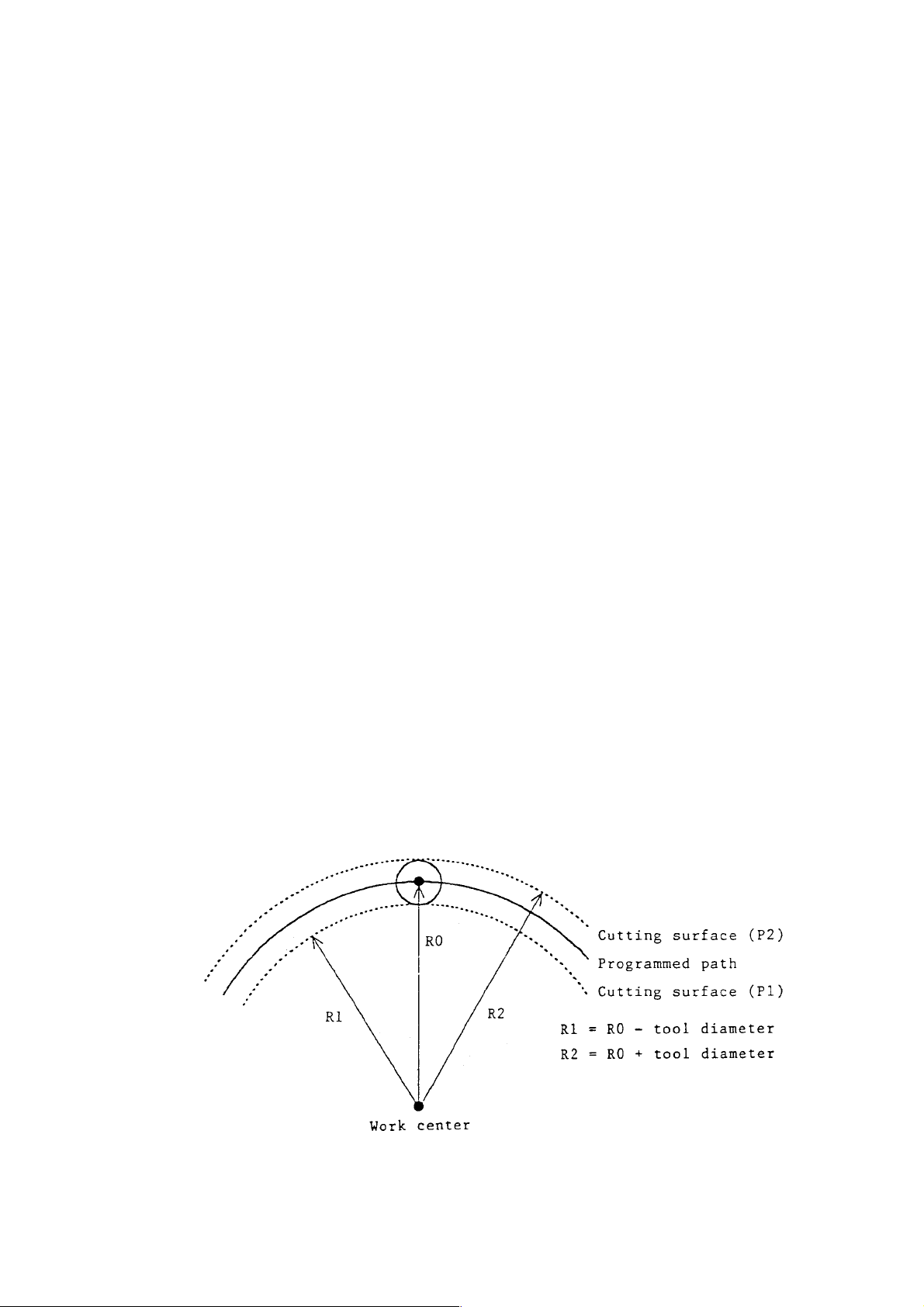
5.3.2 Control Axis
It is necessary to set in advance, in the parameters (linear axis: No.3418, rotating axis:
No.3419), the straight line axis and the rotating axis which are subject to scroll cutting
speed control.
Where, however , No.3418 ≠ No.3419. These parameters will be used for polar coordinate
interpolation (G121) also.
5.3.3 Speed Control Method
The interpolation speed is changed according to the change in the cutting radius, so that
the cutting speed at that position becomes the command speed.
Since a work coordinate value of a straight line axis is employed for the cutting radius (1/2
when the diameter is specified), the origin of the work coordinate system must match the
center of the work rotation.
Since the work coordinate value is not showing the cutting position but the tool center,
however, the speed will not be controlled for the cutting position but the tool center if the
work coordinate is selected as the cutting radius. (The acutual cutting position is equal to
the work coordinate position ± the tool radius.)
When the address P is specified, the cutting radius can be the corrected value of the
absolute work coordinate with the tool radius (addition or subtraction).
P=1 : Outer cutting correction (subtracting the tool radius)
P=2 : Inner cutting correction (adding the tool radius)
Value of P other than above or P omitted: No compensation
(Note 1) Specify address P without the decimal point.
(Note 2) Set the tool compensation amount “R (shape), Q (wear)” in the tool diameter.
The tool diameter becomes R + Q.
Set 9 in the virtual tip point (T). Compensation will not be performed if the value
is other than 9.
5 - 5
Page 70

5.3.4 Speed Changeover Function
By specifying address E (second cutting speed) and address Q (speed changeover
remaining angle) in the same block as G128, the cutting speed can be changed during
execution of that block. When the remaining shift of the rotating axis becomes less than
Q, the cutting speed will be changed from F to E. Both the remaining shift of the rotating
axis and the Q value will be treated as absolute values (no symbols).
This function will be effective when both E and Q are specified and whez Q is not equal to
0. If this condition is not satisfied, the cutting speed will become the normal first cutting
speed F.
Q at this stage indicates the angle, therefore, the position of the decimal point of the data is
the same as the position of the decimal point of the address.
5 - 6
Page 71

5.3.5 Program Example (Straight Line Axis: X Axis, Rot ating Axis: C Axis)
N1 T△△ 00 ;
N2 M13 ; Rotating tool forward rotation
N3 G00 X150.0 Z10.0 C0 ;
N4 X85.0 ;
N5 Z-10.0 ;
N6 G98 G01 X90.0 F2000 ; Approach the start position
N7 G128 X30.0 C-720.0 ;
F800 W600 Q90.0 P2 ; Scroll cutting (inside)
Tool diameter: 5 mm Tool center path (800 mm/min)
○○○
Gutting point path Tool center path (600 mm/min)
5 - 7
Page 72

5.3.6 Precautions
(1) G128 is a one-shot G code and is effective only in the specified block.
(2) The G128 function can be executed only during straight line interpolation (G01) in feed
per minute (G98).
(3) The axes that can be controlled are two in number - the straight line axis and the
rotating axis set in the parameters.
Make sure you specify the two axes in the G128 block and do not specify any other
axis. If this condition is not satisfied, alarm will be output.
(4) When the shift of the straight line axis or the rotating axis is 0, the G128 function
becomes ineffective, similar to the condition when G128 is not specified. (No alarm
will be output.)
(5) Alarm will be output if there is an error in the parameter setting.
• When Parameter No.3418 is equal to No.3419.
(6) Feed override is effective. The specified speed to which override is applied, will
become the cutting speed.
(7) Dry run is effective but the dry run speed will become the compensated speed, and
not the cutting speed. (Same as the condition when G128 is not specified.)
(8) The work coordinate of the straight line axis will be used in the radius value at the
cutting position. Therefore, set the work coordinate system so that the origin of the
work coordinate system is at the center of the work rotation.
(9) The following restrictions will be applied to the coordinate values of the start and end
points of a straght line axis.
• Neither of the specified coordinate values of the start and end points should be zero.
• The signs of the spcified coordinate values of the start and end points should be
equal. (When the start point is positive, the end point should be also positive. When
the start point is negative. the end point should be also negative.)
• Both of the cutting radiuses of the start and end points should not be zero or
negative.
Unless these conditions are met, the alarm will be given.
5 - 8
Page 73

5.3.7 Related Parameters
No.3418 Axis number of straight line axis performing G128 (1 ~ no. of control axes)
No.3419 Axis number of rotating axis performing G128 (1 ~ no. of control axes)
5.3.8 Related Alarms
No.183 Error in the G128 command.
(#001) It is not G98/G01.
(#002) An error exists in an axial command.
(#003) Start/end points of straight line axis are not correct.
No.189 (G128) Error in the parameter setting.
5 - 9
Page 74

5.4 Speed Control of Independent Axis
Offset speed F of the normal axis NC (X, Y, Z etc.) has following meanings.
[1] Supplement of straight line (G01) : speed on diagonal line
[2] Supplement of arc (G02 and G03) : speed on circumference
[3] Wrenching (G32) : speed of an axis with greater amount of movement (lead of screw)
However, the normal speed control is insufficient for axes which move during the planing
and are not involved in the planing, namely “the oscillation halt axis” which is used to halt
oscillation generated during rotation in a long work.
If the oscillation halt axis and the planing axis are specified in the same block, the actual
planing speed does not equal the specified speed F. (The more the movement amount of
the oscillation halt axis increases, the more the planing speed decreases.)
Therefore, the oscillation halt axis is called “independent axis”, and the other axes are called
“the ancillary axes”. And the following function is added.
“Speed control function which makes the planing speed of the ancillary axis
F regardless of the movement amount of the independent axis.”
This control function is called "speed control function of the independent axis".
5.4.1 Specification of Indepandent Axis
It is possible to control, as an independent axis, only one among CNC control axes. The
independent axis is assigned in Parameter No.1012, #6.
(Note) When two or more axes being assigned as independent axes, an axis with the
smallest axis number is controlled as an independent axis.
5.4.2 Control Contents
(1) Block in which speed control of the independent axis is performed
Speed control of the independent axis performed only in blocks which meet the
following conditions.
• G01 (straight line supplement), G32 (wrenching), G34 (wrenching of variable leads)
However, G01 in G128 (scroll planing speed control) is excepted.
• The ancillary axes and independent axes are moving in the same block.
(2) Speed control of independent axis
When speed control of the independent axis is performed, speed of each axis is
controlled in order that;
• Speed of the ancillary axis equals the specified speed F (The same as when
independent axis is not specified.), or
• Speed of the independent axis equals the speed of simult aneous termination of
supplement with ancillary axis.
5 - 10
Page 75

If the supplement distance of the ancillary axes is Ld, and the movement distance of the
independent axes is Li, speed of the independent axis (Fi) is expressed as follows.
Fi = Li × F / Ld (F: Command speed = Speed of ancillary axis)
(Notes) Feeding override is effective. (Speed of each axis is overridden.)
In the case of dry run, speed of ancillary axis becomes the dry run speed.
5.4.3 Operation Examples to be Controlled
If axes X and Z are ancillary axes, axis A is an independent axis, and each axis makes the
following commands from the work coordinates 0, speed of the independent axis is
expressed as follows.
(1) G01 (straight line supplement)
G98 G01 X50.0 Z100.0 A200.0 F100 ;
• Supplement distance of ancillary axis
Ld = (50/2)2 + 1002 = 103.078 (mm)
• Speed of independent axis
Li
Fi =
Ld 103.078
× F =
200 × 100
= 194.028 (mm/min)
(*1) The X axis is processed by radius value conversion.
(*2) Feeding for each rotation is processed by radius value conversion.
(2) G32 (Wrenching)
G32 X50.0 Z100.0 A200.0 F10.0 ;
• Supplement distance of ancillary axis.
Ld = 100 (mm) → Movement amount of the X-axis (25mm) is larger than that of the
Z-axis (100mm)
• Speed of independent axis
Li
Fi =
Ld 100
(*1) In the case of taper wrenching, though this processing method has been
traditionally used, more than two axes can not be specified.
(*2) In the case of G34 (variable lead wrenching), speed of the A-axis varies as the
speed of the independent axis changes.
× F =
200 × 100
= 20.0 (mm/rev)
5.4.4 Operation Not to be Controlled
Special processing is not performed for the code G other than above. And an axis which is
specified as an independent axis is treated as an ancillary axis.
Main codes G not to be controlled are described below.
(1) In the case of G00 (location setting)
Location setting of the non-straight form (standard) and the straight form is performed
as before.
5 - 11
Page 76

(2) In the case of G02 and G03 (arc supplement)
Conventional processing is applied.
• The independent axis is inside the arc surface.
• The independent axis is outside the arc surface.
(3) In the case of fixed cycle (single, complex, holing)
Usually independent axis is not specified in the fixed cycle.
If fixed cycle is specified, and is executable, it will be executed. However, operations
conform to their specifications, because they are composed of G00, G01 and G32.
5.4.5 Notes
(1) If speed control of the independent axis is performed, speed of the independent axis
will be proportional to the ratio of the supplement distance of the ancillary axis and the
movement distance of the independent axis.
Therefore, if [supplement distance of ancillary axis] << [movement distance of
independent axis] (Right side is much larger than left side.), speed of the independent
axis will be excessively high. Therefore, this should be considered when creating
programs.
(2) For the block in which speed control of the independent axis is performed, manual
absolute becomes OFF. (Offset of the amount of manual intervention will not be
performed for the movement after the manual intervention.)
→This cannot happen, but if it is specified, usual arc is executed.
→Helical supplement is executed. Straight line command upon the Helical
supplement effective in only two axes. Therefore, there is no problem in the
execution.
However , alarm is generated, if option of the Helical supplement is not att ached.
5 - 12
Page 77

6. REFERENCE POINT
6.1 Automatic Reference Point Return (G28)
After positioning the axes specified by the program to the intermediate point, a G28
command can automatically return them to the 1st reference point.
6.1.1 Command Format
G28 X___ Y___ Z___ ...... ;
6.1.2 Sample Program
G28 U100. W25. ;
6.1.3 When G28 is Specified without Completing Manual Reference Point Return
After Turning on the Power.
After positioning the program-specified axes to the intermediate point, reference point
return is performed automatically in the same sequence as manual reference point return.
When OT takes place before completion of the reference point returning, following
returning to the deceleration dog, reference point returning is performed once again.
6.1.4 Cautions
(1) If G28 G53 X___ Y___ Z___ ... ; is specified, the axes are positioned to the specified
position of the machine coordinate system, and then, they return to the reference
point.
(2) The G28 command confirms imposition upon return to the reference point.
6.1.5 Related Parameters
No.1225 Machine coordinate values of 1st reference point for each axis
6 - 1
Page 78

6.2 Reference Point Return Check (G27)
After positioning the axes to the program-specified position, a G27 command checks
whether that position is the 1st reference point, and if not, an alarm results.
6.2.1 Command Format
G27 X___ Y___ Z___ ...... ;
6.2.2 Sample Program
G27 X100. Z-50. ;
After the X axis moved to 100.0 and the Z axis to -50.0, it is checked whether they have
returned to the 1st reference point.
6.2.3 Cautions
(1) The position reached with a G27 command includes tool offset, tool nose radius
compensation, and cutter compensation amounts.
(2) Only the axis specified in the G27 block is checked whether it has returned.
(3) No reference point return check is not made on the axis for which the machine lock
function is turned on.
(4) The G27 command confirms imposition after positioning.
6.2.4 Associated Parameters
6.2.5 Associated Alarms
No.F092 It has not been returned to the origin.
6 - 2
Page 79

6.3 Return from Reference Point (G29)
A G29 command positions the program-specified axes from the reference point to the
intermediate point of G28 or G30 specified just before, and then, positions them to the
specified position.
6.3.1 Command Format
G29 X___ Y___ Z___ ...... ;
6.3.2 Sample Program
N1 G28 U100. W25. ;
N2 G29 U-70. W-10. ;
6.3.3 Cautions
(1) If 029 is specified with no G28 or G30 specified once, the intermediate point becomes
zero.
6 - 3
Page 80

6.4 2nd-4th Reference Point Return (G30)
A G30 command can automatically return program-specified axes to the 2nd-4th reference
point after positioning them to the intermediate point.
The 2nd ~ 4th reference points are set in parameters at positions set especially for the
machine.
6.4.1 Command Format
G30 P___ X___ Y___ Z___ ...... ;
P = 2, 3, and 4 correspond to the 2nd through 4th reference points, respectively.
If P is omitted, the 2nd reference point return is assumed.
6.4.2 Sample Program
G30 P3 U100 . W25. ;
6.4.3 Cautions
(1) If G30 G53 X___ Y___ Z___ ...... ; is specified, the axes are positioned to the
specified position of the machine coordinate system, and then, return to the reference
point.
(2) The G30 command confirms imposition upon return to the reference point.
6.4.4 Associated Parameters
No.1226 Machine coordinate value of 2nd reference point of each axis
No.1227 Machine coordinate value of 3rd reference point of each axis
No.1228 Machine coordinate value of 4th reference point of each axis
6 - 4
Page 81

6.5 Floating Reference Point Return (G301)
A G301 command can automatically return the axes specified by the program to the
floating reference point after positioning them to the intermediate point.
The floating reference point is the set position on the machine.
The floating reference point can be set in accordance with the following operation.
6.5.1 Command Format
G301 X___ Y___ Z___ ...... ;
6.5.2 Sample Program
G301 U100. W25. ;
.... Not available with
ΣΣ
Σ21L
ΣΣ
6.5.3 Cautions
(a) G301 G53 X___ Y___ Z___ ; returns the axes to the floating reference point after
positioning them to the specified position of the machine coordinate system.
(b) The G301 command confirms imposition upon return to the floating reference point.
6.5.4 Associated Parameters
No.1229 Floating reference point of each axis
6 - 5
Page 82

6 - 6
Page 83

7. COORDINA TE SYSTEM
7.1 Tool Nose Coordinate System
The tool nose coordinate system always presents the distance between the tool nose
position and machining origin correctly.
Therefore, at the time of zero point return, Z setter, Q setter, or turret index, set the
coordinate system simultaneously to correct to proper coordinate values.
7.1.1 Configuration of the Tool Nose Coordinate System
T ool Offset
T ool Offset
Coordinate System of z-x Plane
Since the tool nose coordinate system is defined as the distance between the tool nose
position and machining origin, the coordinate values are obtained by the following
expressions.
X axis: Work shift amount (XO) + Machine coordinate (Xm) - Tool offset (X) (-External
work origin off set) (Xop)
Y axis: Work shift ainount (YO) + Machine coordinate (Ym) - Tool offset (Y) (- External
work origin offset) (Yop)
Z axis: Work shift amount (ZO) + Machine coordinate (Zm) - Tool offset (Z)-Work Length
[K] (- External work origin off set)(Zop)
7 - 1
Page 84

C axis: Work shift amount (CO) + Machine coordinate (Cm) (- External work origin offset)
(Cop)
B axis: Work shift amount (BO) + Machine coordinate (Bm) (-External work origin off
set)(Bop)
(Note) The OP work origin offset indicates the stun of the “external work origin offset” and
the “thermal displacement work origin offset”, each of which is used optionally.
(1) Work shift amount (X0, Y0, Z0, ...)
Length between the machine origin and jaw end face.
It can be input from [Machining Reference Point Shift] of the [Work Coordinate]
screen.
No input, however, can be made for x axis on this p age. It needs to be input on the
parameter page.
(2) Work length (K)
Length between the chuck jaw end face and machining origin.
It can be input from [Work Length] of the [Work Coordinate] screen.
It can be also altered by executing G54 Z (W)___ ;.
(3) Machining origin
Reference point of the machining program
(4) Tool offset (X, Y, Z)
Tool offset amount. It can be altered in the [T ool] screen.
(5) Outer work origin offset (Xe, Ye, Ze, ......)
Those are offset amount that shift the whole work coordinate system.
Input is possible from the [Outer Offset] in the [Work coordinate] screen.
The specified amount of the outer work origin offset will not, however, become valid
unless the coordinate system (T command, manual turret index and the like) is set.
(The offset amount will not be reflected in the coordinate system.)
7.1.2 Setting of Tool Nose Coordinate System
If the tool is indexed to the cutting position by turret index operation, the coordinate values
of the “tool nose position” will change.
This is because setting of the coordinate system is done in order to correctly display the
distance between the tool nose position and machining origin at any time.
Setting of the coordinate system is done in the following cases:
(1) When T is specified in the automatic (memory, MDI) mode.
(2) When the tool rest is rotated by pressing the turret index switch in the manual (handle,
feed, return to the origin) mode.
(3) When the work length is altered with G54 Z(W) __ ; in the automatic mode.
(4) When the automatic mode is started from the reset state (OP = 0). But ouly when the
parameter No.1202, #3 = 1.
(5) When manual return to the origin is performed.
But only the initial return to the origin as for the straight lire axis.
(6) When measurement is made with Q setter or Z setter.
7 - 2
Page 85

(7) When an offset value for the tool at a cutting position is altered through the screen
input in the manual mode.
(8) When both the work shift and work length are altered in the manual mode.
Axes subject to setting coordinate systems for the above (1) through (8) will be as follows:
(1) through (4): all the axes.
(5) through (8): control axes only
7.1.3 Cautions
(1) If G50 X___ Y___ Z___ ...... ; is executed and the coordinate system is changed, the
coordinate value displayed at [Tool Nose Position] will not coincide with the distance
from the machining origin to the tool nose position.
(2) When the T command and coordinate system setting (G50) are specified in the same
block like G50 X___ Y___ Z___ T___ ;, the T command becomes effective and
G50 is ignored.
(3) As described above, the T-command does not set the coordinate system for the rotary
axis. Therefore, even if a work shift amount for the rotary axis is altered using a G10
command or custom macro, the T-command cannot reflect it in the coordinate
system.
If this is the case, use “work coordinate system preset (G921)” which allows you to
set the work coordinate system independently for each axis with a program
command. (For G921, see Section 7.7.)
But, a coordinate system will not be set for a rotating axis (Parameter No.
1010, #0=1)
7.1.4 Associated Parameters
No.1209 Work length
No.1233 Work shift amount (Work reference point shift amount)
7 - 3
Page 86

7.2 Plane Designation (G17, G18, G19)
With a G17, G18, or G19 command, this function specifies the plane in which circular
interpolation, cutter compensation, etc. are performed.
7.2.1 Command Format
G17 Xp___ Y p___ ; Xp- Yp plane
G18 Zp___ Xp___ ; Zp-Xp plane
G19 Y p___ Zp___ ; Y p-Zp plane
G17 ; X-Y plane
G18 ; Y-Z plane
G19 ; Z-Y plane
where; Xp: X axis or its parallel axis
Yp: Y axis or its parallel axis
Zp: Z axis or its parallel axis
(Note) The
α
- β plane refers to the orthogonal coordinate system which assumes the α-
axis to be the axis of abscissas and the
7.2.2 Sample Program
G17 U0 H0 ; Selects the X-C plane.
G18 W0 D0 ; Selects the Z-B plane.
β
Enables the X-C plane.
-axis to be the axis of ordinates.
7.2.3 Cautions
(1) Set with the parameter to which one of the X, Y, and Z axes the additional axis is
parallel.
(2) The reset state is the G18 mode.
(3) Set properly the relations between the parameter No.1023 (programmed axis name of
each axis) and No.1024 (sets which axis of the basic coordinate system each axis is
to be).
Enables the Z-B plane.
7 - 4
Page 87

(4) An alarm results when the plane is not determined in the block where G17, G18, or
G19 was specified.
(Example) G17 X___ Y___ D___ ;
When the B axis is parallel to the Y axis, it is uncertain whether the X-Y or
X-B plane is selected.
(5) A move command is irrelevant to plane selection.
(6) As an ordinary lathe does not have Y axis, nothing except G18 (Z-X) plane can be
selected.
On the other hand, as a drilling axis in the drilling fixed cycle is set to the basic axes
(X, Y, Z) other than those of the plane, neither X nor Z axis can be assigned as a
drilling axis for G18 plane.
In the above case, set a Y-axis set value (2) to an axis other than control axes of
Parameter No.1024. A vertual Y-axis is set on the coordinate system, where selection
of G17(X-Y)/G19(Y-Z) planes is enabled and drilling with the X or Z axis can be
performed.
(As it is the virtual Y axis on the coordinate system, command of Y axis, even if it is
made, is ignored.
7.2.4 Associated Parameters
No.1023 Programmed axis name of each axis
No.1024 Sets which axis of the basic coordinate system each axis will be.
7.2.5 Associated Alarms
No.106 A plane selection (G17-G19) command has an error.
7 - 5
Page 88
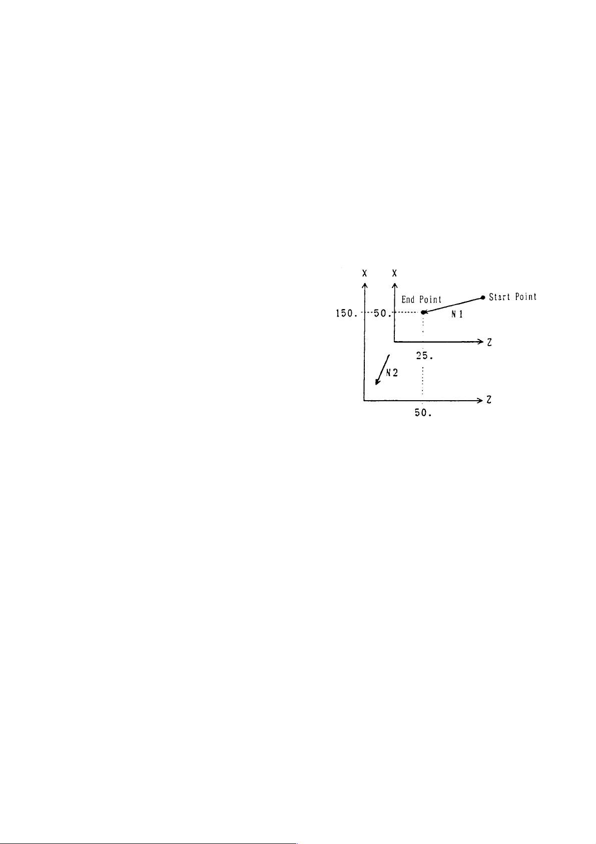
7.3 Work Coordinate System Change (G50)
By specifying G50, you can create the work coordinate system in which a current position
will be a specified one.
7.3.1 Command Format
G50 X___ Y___ Z___ ...... ;
7.3.2 Sample Program
N1 G00 X50. Z25. ;
N2 G50 X150. Z50. ;
If the N2 block is executed, the work
coordinate system will be set so that the
current position will be X = 150.0, Z = 50.0.
7.3.3 Cautions
(1) G50 is effective only in the block where it is specified.
(2) G50 can be specified by both absolute programming and incremental programming.
The axes for absolute programming assume specified coordinate values.
For the axes for incremental programming, the coordinate system is shifted by a
specified amount.
(3) If G50 is specified with tool nose radius compensation or cutter compensation applied,
the work coordinate system is set so that the position before compensation will be a
specified one.
(4) The work coordinate system is validated with a G50 command as follows.
• Set the coordinate system with a T command.
(However, the coordinate system of the rot ating axis makes no change.)
7 - 6
Page 89

7.4 Work Length Modification (G54/G55)
Work length of the front (spindle)/rear (subspindle) sides are changed.
7.4.1 Command Format
G54 Z___ ; (Spindle side: Input of the absolute value of the work length)
W___ ; (Spindle side: Input of the incremental value of the work length)
G55 B___ ; (Subspindle side: Input of the absolute value of the work length)
D___ ; (Subspindle side: Input of the incremental value of the work length)
7.4.2 Notes
(1) Command data of G54 are set in Parameter No.1209.
A command value is written in a parameter in G54, whereas a command value is
added to a parameter in W command.
(2) Command data of G55 are set in Parameter No.1210.
A command value is written in a parameter in B command, whereas a command
value is added to a parameter in D command.
(3) Following G54/G55 command, the coordinate system is automatically set.
(4) Work length is used in the calculation of the corner R coordinate system.
(5) G55 command is useable only when the rear processing function has been provided.
As for the rear face coordinate system, see “19.1 Rear processing.”
7.4.3 Associated Parameters
No.1209 Work length 1 (Spindle side)
No.1210 Work length 2 (Subspinle side)
7 - 7
Page 90

7.5 Machine Coordinate System Selection (G53)
When a G53 command, the axes are positioned to the position of the machine coordinate
system specified by the program.
7.5.1 Command Format
G53 X___ Y___ Z___ ...... ;
7.5.2 Sample Program
G53 X50. Z50. ;
7.5.3 Cautions
(1) An alarm results if an incremental axis command is given.
(2) Specify G53 after cancelling tool nose radius compensation/ cutter compensation.
(3) The G53 command is effective only in the block where it is specified.
7.5.4 Associated Parameters
7.5.5 Associated Alarms
No.146 An incremental axis command has been given for machine Coordinate
System Selection (G53.)
7 - 8
Page 91

7.6 Setting the Local Coordinate System (G59)
You can set another coordinate system (local coordinate system) in the work coordinate
system by specifying the G59 command.
7.6.1 Command Format
G59 X___ Y___ Z___ ...... ;
X, Y, Z: Offsets of local coordinate system(position of origin of local coordinate system
taking the origin of the work coordinate system as the reference)
7.6.2 Program Example
N1 G00 X150. Z50. ;
N2 G59 X100. Z25. ;
If you execute the N2 block, the local
coordinate system will be set with the
values X = 100 and Z = 25 of the work
coordinate system as the origin.
7.6.3 Precautions
(1) G59 is effective only for the specified block.
(2) There is no differentiation in absolute commands/incremental commands for
G59.G59X10.; and G59U10.; are the same.
(3) The local coordinate system will be canceled only for the command axis in case of the
following:
• When an offset of 0 is specified in G59
• When coordinate system is set in G50.
(4) The local coordinate system of all the axes will be canceled in case of the following:
• Reset
• Coordinate system is set in the T command.
7 - 9
Page 92

7.7 Work Coordinate System Preset (G921)
A G921 command can be used to preset the work coordinate system independently for each
axis (setting of the tool nose coordinate system).
It is valid for coordinate system setting of the rotary axis (parameter No.1010, #0 = 1) for
which the coordinate system cannot be set with a T-command.
7.7.1 Command Format
G921 X___ Y___ Z___ C___ ...... ; S pecification of the axis for which you want to preset
the coordinate system.
7.7.2 Sample Program (C-axis = Rotary Axis)
N1 G28 H0 ;.................. Returns the C axis to the zero point.
N2 G50 C0 ;.................. Sets the C-axis zero point to C0.
~~
N3 G10 P0 C___ ; .......Alters a C-axis work shift amount.
N4 G921 C0 ;................ Presets the C-axis work coordinate system.
7.7.3 Cautions
(1) G921 simply specifies the axis for which you want to preset the coordinate system,
and its value has no meaning; X0 and X1.0 have the same meaning.
Also, absolute programming and incremental programming do not make any
difference. (X1 = U1)
7 - 10
Page 93

7.8 Lathe Turning Other than the G18 Plane (Z-X)
The command system and operations in the functions given below differ according to the
selected plane (G17 to G19).
[1] Circular arc interpolation [including helical interpolation] (G02, G03)
*[2] Chamfering, corner R (I, J, K, R)
[3] Arbitrary angle chamfering, corner R (,C/,R)
*[4] Angle-specified straight line interpolation
*[5] Automatic tip R compensation
*[6] Groove width compensation (G150~G152)
[7] T ool diameter compensation (G40~G42)
*[8] Single fixed cycle (G90, G92, G94)
*[9] Compound fixed cycle (G70~G76)
[10] Drilling fixed cycle (G80~G89, G831, G841, G861)
[1 1] Direct tap cycle (G842, G843)
(Note) Items marked with ‘*’ are functions that are unique to lathes.
Lathe turning is normally performed in the G18 plane (horizontal axis: Z axis, longitudinal axis:
X axis).
In this instructional manual also, functions unique to the lathe are described in the G18 plane,
but to rend general purpose features to the NC unit, each function can be executed in other
planes (G17, G19) also. Within the NC unit, the axis commands in the selected plane are
regarded as horizontal axis (longitudinal direction) commands and longitudinal axis (diameter
direction) commands of the plane, and all the commands are executed.
Therefore, commands in other planes are generally executed as described below.
“Axis command” Replaces the X axis and Z axis in the G18 plane by longitudinal axis,
horizontal axis of the selected plane.
“I, J, K” Specifies the X axis direction as I, Y axis direction as J, and Z axis direction
as K.
7 - 11
Page 94

From the axis configuration of the machine, the Z axis becomes the longitudinal direction,
the X axis becomes the diameter direction, and if the Y axis exists then the Y axis also
becomes the diameter direction.
No lathe turning is assumed in the G17 plane but if it is convenient to perform turning in the Y
axis instead of the X axis, then lathe turning in the G19 plane becomes necessary .
However, for the G19 plane, the longitudinal direction becomes the Y axis, and the diameter
direction becomes the Z axis, therefore, the G19 plane cannot be used for functions that
issue the command recognizing the longitudinal direction and the diameter direction ([6], [8],
and [9] mentioned above).
Therefore, the longitudinal direction and the diameter direction for the G19 plane are
regarded as Z axis and Y axis respectively, and the functions of [6], [8] and [9] are executed.
(Take care because these functions will be executed as they are in the G17 plane.)
(Note) Set the virtual tip point (control point) of the tool according to the axis configuration
of the standard plane. (See figure below.)
Automatic tip R compensation will be performed on this plane.
< G19: When the horizontal axis is
taken as the Z axis >
7 - 12
Page 95

Explanations about the “groove width compensation,” “single fixed cycle,” “compound fixed
cycle” are given below. For det ailed explanations, refer to the respective items in the G18
plane.
(1) Groove width compensation (G150 - G152)
[Groove width compensation in the Y-Z plane]
G150 : Cancel groove width compensation
G151 : Groove width compensation for end face / rear end face (Y coordinate system
shift)
G152 : Groove width compensation for outer diameter /inner diameter (Z coordinate
system shift)
The virtual tip point will be changed as shown below.
(2) Single fixed cycle (G90, G92, G94)
Explanations about the fixed cycle of G90 are given here but these are similar for other
fixed cycles also (G92, G94).
[Single fixed cycle in the Y-Z plane (G90)]
G90 Y___ Z___ J___ F___ ;
(Note the J notation carefully)
R : Rapid traverse
F : Cutting feed
(Note 1) Specify the position of C point by Y, Z.
(Note 2) J is the incremental value (radius value) seeing point B with reference to
point C in the Y direction.
7 - 13
Page 96

(3) Compound fixed cycle (G70 - G76)
Specify the X axis direction command “X, U, I” of the G18 plane by the Y axis direction
command “Y, V, J” in the G19 plane.
Explanations about the fixed cycle of G71 are given here, but these are similar to the
explanations for other fixed cycles (G72 - G76).
[Compound fixed cycle (G71) in the Y-Z plane]
F : Cutting feed, R : Rapid traverse
e : Escape amount (PRM6213)
G71 P(ns) Q(nf) V±__ W±__ J±__ K±__ D__ F__ S__ ;
N(ns) ------ ;
Specify the finished shape of A - A’ - B in the block from sequence number (ns) to (nf).
N(nf) ------ ;
P : First sequence number of the finished shape block (ns)
Q : Last sequence number of the finished shape block (nf)
V : Finished shape in the Y direction (∆v)
W : Finished shape in the Z direction (∆w)
J : Y direction allowance of the roughing cycle (∆J)
K : Z direction allowance of the roughing cycle (∆k)
D : Cutting depth (∆d) ...... Specify without notation.
7 - 14
Page 97
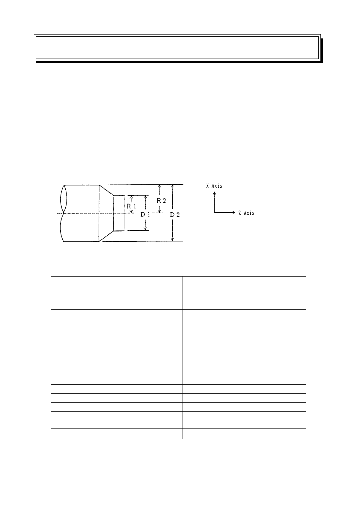
8. COORDINA TE
8.1 Diameter Designation and Radius Designation
The dimensions of each axis can be specified in two methods; using a diameter value or a
radius value. The former is called diameter designation and the latter radius designation.
Although which one is to be specified can be selected by the parameter DIAX (parameter
No.1010; available for each axis), it has been predetermined for each machine. So, make
setting suitable for the mechanical system.
Normally , the NC lathe assumes diameter designation for the X axis, and radius designation
for the other axes. As this may vary from one machine to another, refer to the instruction
manual for each machine.
D1, D2 ...... Diameter designation
R1, R2 ...... Radius designation
When diameter designation is assumed for the X axis, pay attention to the conditions listed in
the following table.
Itemrks Remarks
Non-X-axis command Regardless of the diameter/ radius
(including the incremental command
by the address V. W, D, or H)
X-axis command Specify with a diameter value.
(including the incremental command
by the address U)
Coordinate system setting (G50) Specify the X-axis coordinate value
with a diameter.
X value of the tool position offset amount Specify with a diameter value.
Parameters (D, I, K) for X-axis depth of Specify with a radius value.
cut, etc. used for the canned cycle
(G90, G92, G94, G70-G76, etc.)
Radius for circular interpolation (R, I, K) Specify with a radius value.
Chamfering, corner R amount (R, I, K) Specify with a radius value.
Tool nose radius Specify with a radius value.
Feed rate in the X-axis direction Radius change/rev .,
Radius change/min.
Display of the X-axis position Display with a diameter value.
(Note 1) This manual is described assuming diameter designation for the X axis and
radius designation for the other axes, unless otherwise specified.
8 - 1
Page 98

8.2 Absolute/Incremental Programming (G90, G91)
These G codes are available only when the G code system B or C is selected.
You can select either absolute programming which gives the specified position of the
coordinate system with a value following the axis address, or incremental programming
which gives a stroke from a current position.
8.2.1 Command Format
G90 : Absolute programming
G91 : Incremental programming
8.2.2 Sample Program
8.2.3 Cautions
(1) When the G code system A is selected, specify with an axis command address
instead of using G90/G91. (Refer to “1.1 G Code System”)
(2) The G90 and G91 commands are modal G codes. If one of them is specified, it
remains effective until the other one is specified.
(3) Set with the parameter whether the reset state is to be the G90 or G91 mode.
8.2.4 Associated Parameters
No.3402, #1= 0 The reset state is the G91 mode.
= 1 The reset state is the G90 mode.
8 - 2
Page 99

8.3 Inch/mm Input (G20, G21)
With a G20 or G21 command, either inch or mm system can be selected as the increment
system of program commands.
8.3.1 Command Format
G20 : Inch system
G21 : mm system
8.3.2 The Following Systems of Units are Changed with the G20/G21 Command
(1) Feed rate command with an F code
(2) Commands related to the position
(3) Work origin shift amount
(4) Tool offset amount
(5) Part of parameters
(6) Unit of one graduation of the manual pulse generator
8.3.3 Cautions
(1) S pecify G20/G21 command in an independent block after returning the control axis to
the machine origin.
Note that, with changeover of inch input/mm input (change in G20/G21 command or
the parameter), an axis not on the machine origin enters the origin returning
incomplete state.
(2) When the G20/G21 command is executed, preset the work coordinate system.
8.3.4 Associated Parameters
No.1000, #2 = 0 The input increment system is mm.
= 1 The input increment system is inch.
No.1010, #0 = 0 Enables inch/mm switching for each axis (linear axis)
= 1 Disables inch/mm switching for each axis (rotary axis)
8 - 3
Page 100

8 - 4
 Loading...