

Pursuing the Ideal Compact Inverter
Stöwer Antriebstechnik GmbH, Enneststrasse 3, 51702 Bergneustadt, tel: 02261-40970, Fax: 02261-41309
Pursuing the Ideal Compact Inverter
Series
Designed for excellent performance and user friendliness
2 3
3
4
5
0.5
1 3
6 10 20 30 40 50 60Hz
-100
-200
200
100
0
Speed (min-1)
(%)
Torque
Deceleration Time:
4.2 sec.
Deceleration Time:
1.9 sec.
OFF ON
Motor Current
DC Voltage
Output Frequency
DC Voltage
Output Frequency
Motor Current
Pursuing the Ideal Compact Inverter
Designed for excellent performance and user friendliness
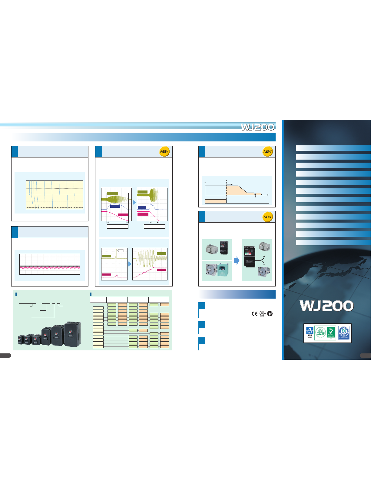
Industry-leading Levels of Performance
High starting torque of 200% or greater achieved
by sensorless vector control
(when sized for heavy duty
).
Speed regulation at low-speed is greatly impro ved.
–
Fluctuation is 1/2* compar ed with the previous model.
–
Trip avoidance functions
Conformity to global st andards
Sink / source logic is standard
Wide input power voltage range
Simple positioning contr ol
(when feedbac k signal is used.)
Induction motor & Permanent magnetic motor *
control with one inverter
(corresponds more than Ver.2.0)
1
2
1
2
3
Integrated auto-tuning function for easy sensorless vector cont rol
realizes high torque suit able for applications requiring it s uch as crane
hoists, lifts, elev ators, etc.
Minimum time deceleration function, over-current suppress function
and DC bus AVR function are incorporated. The functions reduce
nuisance t ripping. Improv ed torque limiting/current limiting function
enables a load limit to prot ect machine and equipment.
Speed regulation at low spe ed has been dras tically improve d to
enhance proce ss stability and precision.
CE, UL, c-UL, c-Tick approvals.
Logic input and output terminal can be congured for sink or source logic.
Input voltage 240V for 200V class and 480V for 40 0V class as standard.
When simple positioning function is activated, speed control operation or
positioning contr ol operation is select able via intellient input. W hile the [SPD]
input is ON, the current position counter is held at 0. When [SPD] is OFF, the
inverter enters positioning control operation and the position counter is active.
The WJ 200 inverter can drive both induc tion motors (IM) and permanent
magnetic mot ors (PM). Energy conservat ion and miniaturi zation can be
achieved using PM motors. Moreover, one inverter used for two types of motor.
Output Frequency
Start position counting
Speed control Position control
Target position
DB
Time
SPD input
ON
Example of Torque Char acteristic s
Model ConfigurationModel Name Indication
WJ200 – 001 L F
with Digit al Operator
Power Source
S: 1-phase 200V class
L: 3-phase 200V class
H: 3-phase 4 00V class
Applied Mot or Capacity
001: 0.1k W – 150 : 15kW
Series Name
PM
WJ200
IM
IM + Inverter
PM + Dedicat ed Contro ller
Auto-tuning to perform sensorles s vector control can now be easily done.
Model Name
WJ200-xxx
1-phase 2 00V clas s 3-phase 200V cla ss 3-phas e 400V c lass
VT CT VT CT VT CT
001 0.2 0.1 0.2 0.1
002 0.4 0.2 0.4 0.2
004 0.55 0.4 0.75 0.4 0.75 0.4
007 1.1 0.75 1.1 0.75 1. 5 0.75
015 2.2 1.5 2.2 1. 5 2.2 1.5
022 3.0 2.2 3.0 2.2 3.0 2.2
030 4.0 3.0
037 5.5 3.7
040 5.5 4.0
055 7.5 5.5 7. 5 5.5
075 11 7.5 11 7. 5
110 15 11 15 11
150 18.5 15 18.5 15
(Example of WJ20 0-055 LF)
• Frequency c ommanded by t he invert er: 0.5H z.
• Motor: H itachi's st andard 3- phase 5.5 kW 4-pol e totally en closed ty pe motor.
Example of Hi tachi's standar d motor. (7.5k W 4-pole)
2.3 sec. re duction of decelera tion time wit hout a braking
resistor i s achieved when the func tion is active.
Over-current Suppress Func tion*
Minimum time deceleration Funct ion
(Example of W J200- 075LF)
* WJ200: 5mi n-1, Previous mo del: 13min
-1
*Turn off this f unction for li fting equip ment.
*Permanen t magnet mot or control f unction of WJ 200 is for va riable torqu e applicatio n such as fan and p ump.
EC97J1095
Features P2–5
Standard Specicatio ns P6
General Specications P7
Dimensions P8
Operation and Programming P9
Termin al (Arrangements /Functions) P 1 0 – 11
Functi on List P 12– 2 0
Protectiv e Functions P 21
Connecting Diagram P 22– 23
OFF ON
Motor Current
Output Frequency
Motor Current
Output Frequency
Trip
Connecting to PLC P24
Wiring and Accessories P 25
For Correct Operation P 26 –27
Global standards
Index
3
Stöwer Antriebstechnik GmbH, Enneststrasse 3, 51702 Bergneustadt, tel: 02261-40970, Fax: 02261-41309

4 5
2
3
3
Watt-hour monitor
Output monitor ing
(2 terminals)
Improvement
of environmen t
2
EU RoHS
compliant
Environment-fr iendly
inverter meet s RoHS
requirements
(ordered items).
Energy consump tion is displayed in kwh.
Two monit or outpu t terminals
(A nal og 0 –10 VDC
(10-bit), pulse train (0–10VDC, max 32kHz))
.
5
EzCOM (Peer-to-Peer communication)
WJ200 supports Peer-to-Peer communication between multiple
inverters. One administrator inver ter is necessary in the networ k, and
the other inverters act as master or slave.
Varnish coating of
internal PC boar d is
standard.
(Logic PCB an d I/ F PCB ar e
excluded.)
Dual rating
1
WJ200 can be used for both heavy and
normal duty. One-frame-size smaller WJ200
can be applicable to cer tain applications.
Built-in BRD circuit
4
Built-in BRD circuit for all models (Op tional resist or).
1
6
5 7
4
Network compatibility & Ex ternal port s
2
3
Safe stop fun ction
(planning)
Password function
1
Easy sequence [EzS Q]
programming function
Pursuit of Ease of Use
Ease of Maintenance Environmental Friendliness
Long life time components
(Design life time 10 years or more*)
Easy-removable
cooling fan
Micro surge voltage suppress
function
(Patent re gistered)
Life time warning function
1 3
2
Sequence oper ation is realized by dow nloading to an inverter a
program crea ted with Hitachi's Ez SQ software. Us er program can
be compiled on E zSQ software on a PC. Exter nal components can
be simplied or eliminat ed, resulting in cost-sa vings.
Design lifetime 10 Years or more for D C bus
capacitors and c ooling fan.
Cooling fan ON /O FF control function fo r longer
fan life.
*Ambient temp erature : Av erage 40ºC (
no corrosiv e gases, oil mis t or dust
)
Design lifet ime is calculat ed, and not gua ranteed.
The cooler fan can b e exchanged
without special t ools.
Hitachi original P WM control method
limits motor termin al voltage to less than
twice inver ter DC bus voltage.
Lower than Hit achi motor max. insulation
voltage (1,250V )
(During rege neration, t he motor ter minal volta ge may exceed
the motor ma ximum insulat ion voltage (1, 250V))
WJ200 diagnoses lif etime of DC bus capacitors
and cooling fan(s).
The WJ200 inverter has a pas sword function t o prevent changing
parameters or to hide some or all par ameters.
Only one MC is enough
•Reduction in costs.
•Miniaturization
Safety Module
ST01 (GS1)
ST02 (GS2)
EDM
Safety terminal
(In/ output)
Emergency output
shut-down
via hardware
Safety SW
(Emergency Stop)
Top cover can
be removed
with nger tips.
Remove cooling
fan after
disconnect ing
power plug.
Motor ter minal voltag e
Easy to maintain
Easy select ion of displayed par ameters
●
Data compar ison function
Display paramete rs changed from def ault setting.
●
Basic display
Display most fre quently used parame ters.
●
Quick display
Display 32 user-selec ted parameters.
●
User-changed parameter display
Store automa tically and display the par ameters changed by
the user (Up to 32 sets); can also be used as change histor y.
●
Active pa rameter display
Display those par ameters which are en abled.
Inverters can be ins talled
with no space between them
to save space in the panel.
*Ambient temp erature 4 0ºC max.,
individual mounting.
Side-by-side ins tallation
6
Automatic r eturn to the initial display: 10 min. a fter the last
key operation , display returns to th e initial parameter se t.
Display limitatio n:
Show only the con tents of display par ameter.
Dual monitor: Two arbi trary monitor it ems can be set. Par ameters
are switche d by up/down keys.
Flexible display funct ions
Various Versatile Functions
Ease of wiring
Screw-less t erminals (control circuit
terminals) spring-lo aded, for use with
solid or strande d wire with ferrules.
Screw-less terminals
(Control circui t terminals)
E=625V cable:100m
A serial RS-4 85 Modbus/RT U port is stand ard. The WJ200 can
communicate via DeviceNet, CompoNe t, PROFIBUS and C ANopen
with optional e xpansion card
(planned) . USB (Mini-B c onnector) port
and RS-42 2 (RJ45 connect or) port are stan dard.
USB port
RS42 2 port
1st 2nd 3rd 4th 5th 6th 7th
Night time
Standard driving
(Frequency is constant.)
WJ200 driving
Motor Speed
date
●
EzSQ E xample: Energy cos t saving by speed r eduction.
■Daytime: Motor speed is automatically reduced to reduce demand during peak hours.
■Nighttime: Motor spee d is increased to t ake a advantag e of off-peak p ower rates.
Example of d riving progra m
Operation panel
(Switc h/tim er etc.)
Panel lead
Standard Inverter WJ200 U sing EzSQ
RUN
STOP
RESET
POWER
Hz
A
RUN
PRG
MAX
MIN
WJ200 confor ms to the applicable safet y standards and cor responds
to Machinery Dire ctive of Europe. Shut s down the inverter b y
hardware, byp assing the CPU, to achieve r eliable safe stop function.
The safet y standard can be met at a low cost.
(ISO13849 -1 Category 3 / IE C60204 -1 Stop Categor y 0)
One network ex pansion card can
be installed ins ide the WJ2 00.
Inverter
WJ200
Operation panel
(Switc h/tim er etc.)
Rely seque nce
Conventional
Inverter
Panel lead
Stöwer Antriebstechnik GmbH, Enneststrasse 3, 51702 Bergneustadt, tel: 02261-40970, Fax: 02261-41309

Standard Specications
Stöwer Antriebstechnik GmbH, Enneststrasse 3, 51702 Bergneustadt, tel: 02261-40970, Fax: 02261-41309
1-phase 200V class
Models WJ2 00- 00 1SF 002SF 004SF 007SF 0 15 S F 022SF
VT 0.2 0.4 0.55 1.1 2.2 3.0
kW
Applicable mot or size *
Rated capaci ty (kVA)
Input
Rating
Output
Rating
Minimum value of r esistor (Ω) 10 0 100 100 50 50 35
Weight
Rated input volt age (V ) 1-phase: 20 0V-15% to 240 V +10%, 50 / 60Hz ±5%
Rated inpu t current (A)
Rated output voltage (V) *
Rated output current (A)
1
3-phase 200V class
Models WJ2 00- 001L F 002LF 004LF 007LF 015 LF 022LF 037LF 055LF 075LF 110 LF 150 LF
Applicable mot or size *
Rated capaci ty (kVA)
Input
Rating
Output
Rating
Minimum value of r esistor (Ω) 100 10 0 100 50 50 35 35 20 17 17 10
Weight
Rated input volt age (V ) 3-phase: 200V-15% to 240V +10%, 5 0/ 60Hz ±5%
Rated inpu t current (A)
Rated output voltage (V) *
Rated output current (A)
1
CT 0.1 0.2 0.4 0.75 1.5 2.2
VT 1/4 1/2 3/4 1.5 3 4
HP
CT 1/8 1/4 1/2 1 2 3
VT 0.4 0.6 1. 2 2.0 3.3 4 .1
200V
CT 0.2 0.5 1.0 1.7 2.7 3.8
VT 0.4 0.7 1.4 2.4 3.9 4.9
240V
CT 0.3 0.6 1.2 2.0 3.3 4.5
VT 2.0 3.6 7.3 13.8 20.2 24.0
CT 1.3 3.0 6.3 11.5 16 .8 22.0
2
VT 1.2 1.9 3.5 6.0 9.6 12. 0
CT 1.0 1.6 3.0 5.0 8.0 11.0
kg 1.0 1.0 1.1 1.6 1.8 1. 8
lb 2.2 2.2 2.4 3.5 4.0 4.0
VT 0.2 0.4 0.75 1.1 2.2 3.0 5.5 7.5 11 15 18.5
kW
CT 0.1 0.2 0.4 0.75 1.5 2.2 3.7 5.5 7. 5 11 15
VT 1/4 1/2 1 1.5 3 4 7. 5 10 15 20 25
HP
CT 1/8 1/4 1/2 1 2 3 5 7. 5 10 15 20
VT 0.4 0.6 1.2 2.0 3.3 4.1 6.7 10. 3 13.8 19.3 23.9
200V
CT 0.2 0.5 1.0 1.7 2.7 3.8 6.0 8.6 11. 4 16. 2 20.7
VT 0.4 0.7 1.4 2.4 3.9 4.9 8.1 12.4 16.6 23.2 28.6
240V
CT 0.3 0.6 1.2 2.0 3.3 4.5 7.2 10.3 13.7 19.5 24.9
VT 1.2 1.9 3.9 7.2 10.8 13.9 23.0 3 7.0 48.0 68.0 72.0
CT 1.0 1.6 3.3 6.0 9.0 12 .7 20.5 30.8 39.6 57.1 62.6
2
VT 1.2 1.9 3.5 6.0 9.6 12. 0 19.6 30.0 40.0 56.0 69.0
CT 1.0 1.6 3.0 5.0 8.0 11.0 17.5 25.0 33.0 47. 0 60.0
kg 1.0 1.0 1.1 1.2 1.6 1.8 2.0 3.3 3.4 5.1 7.4
lb 2.2 2.2 2.4 2.6 3.5 4.0 4.4 7.3 7. 5 11. 2 16.3
3-phase: 200 to 240V (proportional to input voltage)
3-phase: 200 to 240V (proportional to input voltage)
3-phase 400V class
Models WJ2 00- 004HF 007HF 015HF 022HF 030HF 040HF 05 5HF 075HF 110HF 15 0HF
VT 0.75 1. 5 2.2 3.0 4.0 5.5 7. 5 11 15 18 .5
kW
Applicable mot or size *
Rated capaci ty (kVA)
Input
Rating
Output
Rating
Minimum value of r esistor (Ω) 180 180 180 100 100 100 70 70 70 35
Weight
*1: The ap plicable mot or refers t o Hitachi st andard 3- phase mot or (4p). Whe n using other motors, ca re must be ta ken to prev ent the rat ed motor cur rent (50/ 60Hz) fr om exceedi ng the rate d output cu rrent of th e inverte r.
*2: Th e output vo ltage vari es as the main s upply volt age varies (e xcept when using the AVR f unction). In any case, t he output v oltage can not exceed the input po wer supply v oltage.
6
Rated input volt age (V ) 3-phase: 380V-15% to 480 V +10%, 50 / 60Hz ±5%
Rated inpu t current (A)
Rated output voltage (V) *
Rated output current (A)
1
CT 0.4 0.75 1.5 2.2 3.0 4.0 5.5 7.5 11 15
VT 1 2 3 4 5 7. 5 10 15 20 25
HP
CT 1/2 1 2 3 4 5 7. 5 10 15 20
VT 1. 3 2.6 3.5 4.5 5.7 7.3 11.5 15.1 20.4 25.0
200V
CT 1.1 2.2 3.1 3.6 4.7 6.0 9.7 11. 8 15.7 20.4
VT 1. 7 3.4 4.4 5.7 7.3 9.2 14.5 19.1 25.7 3 1.5
240V
CT 1.4 2.8 3.9 4.5 5.9 7. 6 12.3 14.9 19.9 25.7
VT 2.1 4.3 5.9 8.1 9.4 13.3 20.0 24.0 38.0 44.0
CT 1.8 3.6 5.2 6.5 7.7 11.0 16.9 18.8 29.4 35.9
2
VT 2.1 4.1 5.4 6.9 8.8 11.1 17.5 23.0 31.0 38.0
CT 1.8 3.4 4.8 5.5 7.2 9.2 14.8 18. 0 24.0 31.0
kg 1.5 1.6 1.8 1.9 1. 9 2.1 3.5 3.5 4.7 5.2
lb 3.3 3.5 4.0 4.2 4.2 4.6 7.7 7. 7 10.4 11. 5
3-phase: 380 to 480 V (proportional to input voltage)

General Specications
Stöwer Antriebstechnik GmbH, Enneststrasse 3, 51702 Bergneustadt, tel: 02261-40970, Fax: 02261-41309
Item General Specications
Protect ive housing *
3
Control method Sinusoidal Pulse Width Modulation (PW M) control
Carrier frequency 2kHz to 15kHz (derating required depending on the model)
Output f requency range *
4
Frequency accuracy
Frequency set ting resolut ion Digital: 0.01Hz; Analog: max . frequency / 1000
Volt ./ Freq. character istic
Overload capacity
Acceleration /deceleration time 0.01 to 3600 seconds, linear and S-curve accel /decel, second accel /decel setting available
Start ing torque 200% @0.5Hz (sensorless ve ctor control)
DC braking Variable operating f requency, time, and braking force
Operator panel
Freq . setting
Ex ternal signal *
Via network RS485 ModBus RT U, other net work option
Operator panel Run / Stop (For ward /Reverse run change by command)
FW D/ REV run
Ex ternal signal *
Via network RS485 ModBus RT U, other net work option
Terminals 7 terminals, sink / source changeable by a short bar
Intelligent input
Input signal
terminal
68 funct ions
Functions
assignable
Intelligent output
terminal
Functions
48 f unctions
assignable
Output signal
Moni tor output (analog) Output freq., output current, output torque, output voltage, input power, thermal load ratio, L AD freq., heat sink temperature, general ou tput (EzSQ)
Pulse train output
(0 – 10VDC, 32 kHz max.)
Alar m output cont act ON for inverter alar m (1c contacts, both normally open or closed available.)
Other functions
Protect ive funct ion
Temperature Op erating (ambient): -10 to 50
Operating environment
Humidity 20 to 90% humidity (non-condensing)
Vibration *
Location Altitude 1,000m or less, indoors (no corrosive gasses or dust)
Coat ing color Black
Options Remote operator unit, cables for the units, braking unit, braking resistor, AC reactor, DC reactor, EMC lter
IP20
0.1 to 400Hz
Digital command: ±0.01% of the maximum frequency
Analog command: ±0.2% of the maximum frequency (25
°
C ±10°C)
V/f control (constant torque, reduced torque, free-V /F): b ase freq. 3 0Hz – 400Hz adjustable,
Sensorless vector control, Closed loop control with motor encoder feedback (only V/f control).
Dual rating: CT (Heavy duty): 60 sec. @150%
VT (Normal dut y): 60 sec. @120%
2
1
keys / Value set tings
6
0 to 10 VDC (input impedance 10kΩ), 4 to 20mA (input imp edance 100Ω), Potentiometer (1k to 2kΩ, 2W )
6
Forward r un /stop, Reverse run / stop
FW (forward run command), RV (reverse run command), CF1 – CF4 (multi-stage speed setting), JG (jog command), DB (external braking), SET (set second
motor), 2CH (2-stage accel. /decel. command), FRS (free run stop command), E XT (exter nal trip), USP (st artup function), CS (commercial power switchover),
SFT (soft lock), AT (analog input selection), RS (reset), P TC (thermistor thermal protection), STA (start), STP (stop), F /R (forward /reverse), PID (PID
disable), PIDC (PID reset), UP (remote control up function), DWN (remote control down function), UDC (remote control data clear), OPE (operator control),
SF1– SF7 (multi-stage speed setting; bit operation), OLR (overload restriction), TL (torque limit enable), TRQ1 (torque limit changeover1), TRQ2 (torque
limit changeover2), BOK (Braking conrmation), L AC (LAD cancellation), PCLR (position deviation clear), ADD (add frequency enable), F-TM (force terminal
mode), ATR (permission of torque command input), KHC (Cumulative power clear), MI1– MI7 (general purpose inputs for EzSQ), AHD (analog command hold),
CP1– CP3 (multistage-position switches), ORL (limit signal of zero-return), ORG (trigger signal of zero-return), SPD (speed/position changeover), GS1,GS2 (STO
inputs, safety related signals), 485 (Starting communication signal), PRG (executing EzSQ program), HLD (retain output frequency), ROK (permission of run
command), EB (rotation direction detection of B-phase), DISP (display limitation), NO (no function)
RUN (run signal), FA1 –FA 5 (frequency arrival signal), OL,OL2 (overload advance notice signal), OD (PID deviation error signal), A L (alarm signal),
OTQ (over / under torque thre shold), UV (under-voltage), TRQ (torque limit signal), RNT (run time expired), ONT (power ON time expired), THM (thermal
warning), BRK (brake release), BER (brake error), ZS (0Hz detection), DSE (speed deviation excessive), POK (positioning completion), ODc (analog
voltage input disconnection), OIDc (analog cur rent input disconnection), FB V (PID second stage output), NDc (network disconnec t detection), LOG1 –
LOG3 (Logic output signals), WAC (capacitor life warning), WA F (cooling fan warning), FR (st arting contact), OHF (heat sink overheat warning), LOC
(Low load), MO1 –MO3 (general outputs for EzSQ), IRDY (inver ter ready), FWR (forward operation), RVR (reverse operation), M JA (major failure),
WCO (window comparator O), WCOI (window comparator OI), FREF (frequency command source), REF (run command sour ce), SETM (second motor in
operation), EDM (STO (safe torque off ) per formance monitor), OP (option control signal), NO (no function)
[PW M output]
Output fre q., output current, output torque, output voltage, input power, thermal load ratio, LAD freq., heat sink temperature, general output (EzSQ)
[Pulse train output]
Output frequency, output cur rent , pulse train input monitor
Free-V/f, manual / automatic torque boost, output voltage gain adjustment, AVR function, reduced voltage start, motor data selection, autotuning, motor stabilization control, reverse r unning protection, simple position control, simple torque control, torque limiting, automatic carrier
frequency r educ tion, energy saving operation, PID function, non-stop operation at instantaneous power failure, brake control, DC inje ction
braking, dynamic braking (BRD), f requency upper and lower limiters, jump frequencies, curve accel and decel (S, U, inversed U,EL-S), 16-stage
speed prole, ne adjustment of st art frequency, accel and decel stop, process jogging, frequency calculation, frequency addition, 2-stage
accel/decel, stop mode selection, start /end freq., analog input lter, window comparators, input terminal response time, output signal delay/
hold function, rotation direction restriction, stop key sele ction, sof tware lock, safe stop function, scaling function, display restriction, passwor d
function, user p arameter, initialization, initial display selection, cooling fan control, warning, trip retry, frequency pull-in r estart, frequency
matching, overload restriction, over current restriction, DC bus voltage AVR
Over-current, over-voltage, under-voltage, overload, brake resistor overload, CPU error, memory error, external trip, USP error, ground fault detection
at power on, temperature error, internal communication error, driver error, thermistor error, brake error, safe stop, overload at low speed, modbus
communication error, option error, encoder disconnection, speed excessive, EzSQ command error, EzSQ nesting error, EzSQ execution error, EzSQ user trip
°
C / Stor age: -2 0 to 65°C *
8
5.9m/s2 (0.6G), 10 to 55 Hz
7
*3: Th e protect ion method conforms t o JEM 1030.
*4: To operat e the motor b eyond 50 / 60Hz, c onsult the m otor manuf acturer f or the maxim um allowable r otation sp eed.
*5: Th e brakin g torque via ca pacitive feedbac k is th e averag e decele ration t orque at the sh ortest deceler ation (st opping f rom 50 / 60Hz as indic ated). I t is no t continu ous rege nerative braking torque. The a verage d ecelerati on
torqu e varies wit h motor los s. This value d ecreases w hen opera ting beyon d 50Hz. If a large rege nerative t orque is req uired, the o ptional reg enerativ e braking uni t and a resis tor should be u sed.
*6: T he frequenc y command is t he maximum f requency a t 9.8V for inp ut voltage 0 t o 10VDC , or at 19.6mA fo r input curr ent 4 to 20mA . If this char acterist ic is not satis factory f or your applic ation, cont act your Hit achi repre sentativ e.
*7: The stora ge tempera ture refe rs to the sho rt-term t emperatur e during tr ansport ation.
*8: Co nforms to t he test met hod speci ed in JIS C0 040 (1999) . For the mo del types excluded in t he standar d specic ations, con tact your H itachi sale s represe ntative.
7

Dimensions
Stöwer Antriebstechnik GmbH, Enneststrasse 3, 51702 Bergneustadt, tel: 02261-40970, Fax: 02261-41309
• WJ200-001LF – 007LF
• WJ200-001SF – 004SF
68 (2.68)
WJ200 INVERTER
PWR
RUN
Hz
ALM
A PRG
STOP
RUN
1
RESET
ESC
2 SET
128 (5.04)
118 (4.65)
5 (0.20)
56 (2.20)
D
Ø4.5 (0.18)
Model D
001LF, 002LF
001SF, 00 2SF
109 (4. 29)
004 LF, 004SF 122. 5 (4.82)
007LF 145.5 ( 5.73)
• WJ200-055LF
• WJ200-075LF
• WJ200-055HF
• WJ200-075HF
248 (9.76)
260 (10.24)
155 (6.10)
140 (5.51)
6 (0.24)
122 (4.80)
[Unit : mm(inch)]
Inche s for refere nce only
Ø6 (0.24)
WJ200 INVERTER
PWR
RUN
Hz
ALM
A
PRG
STOP
RUN
1
RESET
ESC
2 SET
• WJ200-015LF, 022LF
• WJ200-007SF – 022SF
• WJ200-004HF – 030HF
108 (4.25)
WJ200 INVERTER
RUN
Hz
A PRG
STOP
RUN
1
RESET
ESC2SET
128 (5.04)
118 (4.65)
5 (0.20)
96 (3.78)
D
• WJ200-037LF
• WJ200-040HF
140 (5.51)
WJ200 INVERTER
RUN
1
ESC2SET
128 (5.04)
118 (4.65)
• WJ200-110LF
• WJ200-110HF
• WJ200-150HF
Ø4.5 (0.18)
PWR
ALM
296 (11.65)
Model D
004HF 143.5 ( 5.65)
Other 170.5 (6.7 1)
175 (6.89)
284 (11.18)
7 (0.28)
180 (7.09)
WJ200 INVERTER
STOP
RUN
1
RESET
ESC2SET
160 (6.30)
Ø7 (0.28)
RUN
PWR
Hz
ALM
A
PRG
• WJ200-150LF
220 (8.66)
Ø7 (0.28)
WJ200 INVERTER
RUN
PWR
Hz
ALM
A
PRG
STOP
RUN
PWR
RUN
Hz
ALM
A PRG
STOP
RESET
Ø4.5 (0.18)
336 (13.23)
350 (13.78)
ESC2SET
1
RESET
5 (0.20)
128 (5.04)
170.5 (6.71)
8
175 (6.89)
7 (0.28)
192 (7.56)

Operation and Programming
Stöwer Antriebstechnik GmbH, Enneststrasse 3, 51702 Bergneustadt, tel: 02261-40970, Fax: 02261-41309
Operation Panel
WJ200 Series can be easily operated with the digital operator provided as standard.
( 4 ) Run LED
ON when inverter is in RUN mode.
( 5 ) Monitor L ED [Hz]
ON (Green) when the displayed data is
frequency related.
( 6 ) Monitor LED [A]
ON (Green) when the displayed dat a is
current related.
( 8 ) 7-segment L ED
Shows each parame ter, monitors etc.
( 7 ) Run command LED
ON (Green) when the Run command is set to the
operator. (Run key is enabled.)
( 9 ) RUN key
Makes inver ter run.
(11) Escape key
Go to the top of next function group,
when function mode is displayed.
(12) Up key (13) Down key
Press up or down to sequence through parameters and functions
shown on the display, and increment/decrement values.
(1 ) POWER LED
ON (Green) while t he inverter is receiving
input power.
( 2 ) AL ARM LED
ON (Red) when the inver ter trips.
( 3 ) Program L ED
ON (Green) when the display shows
editable parameter.
(15) USB port
USB connector (mini-B) for PC communication.
(10) Stop /reset key
Makes inverter stop.
(16) RS-422 port
RJ4 5 jack for remote operator.
(14) Set key
Function code: Moves to the data display.
Data code: Press to write the new value
to EEPROM.
Keypad Navigation Map Single-Digit Edit Mode
If a target function code or data is far from current
posit ion, using the single-digit edit mode makes it
quicker to navigate there. Pressing the up key and
down key at the same time brings you into the
digit-by-digi t navigation mode.
Press both up key and down key at
Step1:
the same.
1st digit will be blinking.
Group "d"
Function co de
Group "F "
Function co de
Func tion code di splay
:
Moves to dat a display
Data display
Func tion code di splay
: Chang e the value of fun ction code.
Pressing the up key at the bot tom of the group returns to the top of the group.
Func tion code di splay
: Jumps t o the next gr oup
Save
Data display
d001: Output frequency monitoring
F001: Output frequency setting
Function group "d" is a monitor,
data c annot be changed.
Data display (F001 to F003)
Data d oes not blink becaus e of real time s ynchronizing
Save s the data in EE PROM and re turns to functio n code display.
Group "A"
Function co de
Group "b"
Group " C"
Group " H"
Group " P"
Group " U"
Group "d"
return to d 001
)
Data display
Function group "U" return to function group "d" next.
A001: Frequency source setting
Data display
When data is changed, the display starts blinking, which
means that new data has not been stored yet.
: Saves the data in EEPROM and returns to function code display.
: Cancels the data change and returns to function code display.
The blinking digit is moved by the
Step2:
ESC
and
SET
key right and left.
Use up/down keys to change the value
of the digit.
+1
SETESC
Move cursor to left. Move cursor to right.
Step3:
-1
When the least signicant digit is
blinking, the
SET
key selects
that parameter.
SET
9
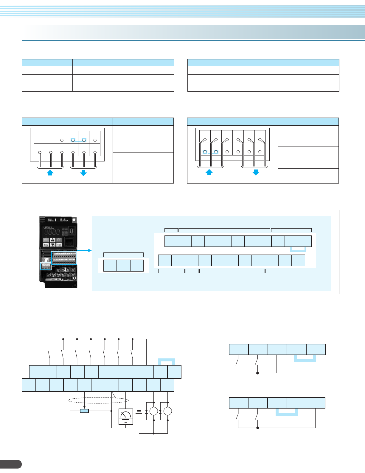
Terminal (
Stöwer Antriebstechnik GmbH, Enneststrasse 3, 51702 Bergneustadt, tel: 02261-40970, Fax: 02261-41309
Arrangements / Functions
Terminal Description
Symbol Terminal Name
R/L1, S/L 2, T/L3 Main power supply input terminals
U/T1, V/T2, W/T3 Inver ter output terminals
PD/+1, P/+ DC reactor connection terminals
Terminal Arrangement and Screw Diameter
Terminal Model
Screw Diameter
)
Symbol Terminal Name
P/+, RB External braking resistor connection terminals
P/+, N/- External braking unit connection terminals
G Ground connection terminal
Terminal Model
Screw Diameter
RB
PD/+1
P/+ N/-
R/L1 S/L2 T/L3 U/T1 V/T2 W/T3
001 – 007LF
001 – 004SF
M3.5
015 – 037LF
007– 022SF
Power input Output to motor
004 –040HF
Terminal Arrangement of Control Circuit Terminals
Relay contacts
AL2 AL1 AL0
M4
RS-485
comm.
R/L1 S/L2
PD/+ P/+
Power input Output to motor
RS-485
comm.
SN
7 6 5 4 3 2 1 L PLC P24
SP
EO EA H O OI L AM CM2 12 11
Pulse
Pulse
Train
Train
output
input
T/L3 U/T1 V/T2 W/T3
N/-
RB G G
Logic inputs
Analog input A nalog output Logic outputs
055 – 075LF
055 – 075HF
110LF
110 – 150HF
150 LF M8
Logic common
and power supply
M5
M6
Short bar
Wiring sample of control logic terminal (Sink logic)
Sink /source logic of intelligent input terminals
Sink or source logic is switched by a short bar as below.
Sink logic
Short bar
(Sink logic)
SN 7 6 5 4 3 2 1 L PLC P24
SP EO EA H O OI L AM CM2 12 11
Variable resistor
for freq. set tting
(1kΩ –2kΩ)
10
Freq. meter
(27Vdc 50m A max.)
RYRY
Source logic
2 1 L PLC P24
Short bar
2 1 L PLC P24
Short bar

Hardware Switches
Stöwer Antriebstechnik GmbH, Enneststrasse 3, 51702 Bergneustadt, tel: 02261-40970, Fax: 02261-41309
a Termination resistor
selection switch
OFF
(Default)
b
Safe stop function
selection switch
ON
Switch Name Switch Name Description
a
Termination resistor
selec tion switch
b
Safe stop function
selec tion switch
Disable d
(Default)
c
EDM function selection switch
Terminal 11
(Default)
Enabled
EDM
output
c
EDM func tion
selec tion switch
Terminal Functions
Symbol Terminal Name Description /Ratings
Power supply
Frequency setting
Analog
Sensor inpu t 5/PTC Motor thermistor input Connec t motor thermistor bet ween PTC and L terminal to detect the motor temperature. Set 19 in C005
Monitor Ou tput AM Analog voltage output 0 to 10VDC 2mA max.
Power supply
Contact
Input
Pulse
Digital
Open collector
Output
Relay
Pulse EO Pulse train output
Serial communication port SP, SN Serial communication terminal For RS485 Modbus communication.
L GND for analog signals Sum of [OI], [O], and [H] currents (return)
H +10V analog reference 10VDC nominal, 10mA max.
O Analog voltage input 0 to 9.8 VDC range, 10 VDC nominal,input impedance 10 kΩ
OI Analog current input 4 to 19.6 mA range, 20 mA nominal, input impedance 10 0 Ω
L GND for logic inpu ts Sum of input [1] – [7] currents (return)
P24 +24V for logic input s 24VDC, 30mA. (do not short to terminal L )
PLC Intelligent input common
7
6
Discrete logic inputs
5
(Terminal [3],[4],[ 5] and [7] have
4
dual function. See following
3
description and related pages for
2
the det ails.)
1
3/GS1 Safe stop input GS1
4/GS2 Safe stop input GS2
EA Pulse train input A
7/EB Pulse train input B
Discrete logic outputs [11]
11/E DM
(Terminal [11] has dual function.
See following description and
related pages for the details.)
11
Discrete logic outputs [12]
12
CM2 GND for logic output 100 mA: [11], [12] current ret urn
AL0 Relay common contact
AL1 Relay cont act, normally open
AL2 Relay contact, normally closed
Source type (connecting [P24] to [1] – [7] turns each input ON).
Sink type (connecting [L] to [1] – [7] makes each input ON.)
[Input ON condition]
Voltage bet ween each terminal and PLC: 18VDC min.
[Input OFF condition]
Voltage bet ween each terminal and PLC: 3V DC max.
Allowable voltage between each ter minal and PLC: 27VDC max.
(use PLC or an exter nal supply referenced to terminal L)
Functionality is based on ISO13849 -1
See appendix for the details.
32kH z max .
Common is [L]
2kHz max.
Common is [PLC]
50mA max. ON st ate current,
27 VDC max. OFF state voltage
Common is CM2
In case the EDM is sele cted, the functionality is based on ISO138 49-1
4VDC max. ON state voltage depression
50mA max. ON st ate current,
27 VDC max. OFF state voltage
Common is CM2.
Maximum capacity of relays
AL1– AL0: 250VAC, 2A (R load)/ 0.2A (L load)
30VDC, 3A (R load)/ 0.6A (L load)
AL2 – AL0: 250VAC, 1A (R load)/ 0.2A (L load)
30VDC, 1A (R load)/ 0.2A (L load)
Minimum capacity of relays
AL1– AL0, AL2– AL0: 100VAC, 10mA / 5VDC, 100m A
10VDC 2mA ma x.
32kH z max .
Termination resistor for the RS-485
communication por t.
WJ200 has a built-in 200Ω resistor
activated by a DIP switch.
To enable the Safe stop function, set the
DIP switch ON.
Before operating switch, make sure that
the input power supply is off.
To enable the EDM function, set the DIP
switch ON.
Before operating switch, make sure that
the input power supply is off.
11

Function List
Stöwer Antriebstechnik GmbH, Enneststrasse 3, 51702 Bergneustadt, tel: 02261-40970, Fax: 02261-41309
If a desired parameter is not displayed, check the setting of function "b037"(function code display restriction). To display all parameters, specif y "00" for "b037".
Code Fun cti on Nam e Setting Range
d001 Outp ut freque ncy monito ring 0.00 to 99.99 / 100.0 t o 400.0 [ Hz] ○ ○ —
d002 Outp ut curren t monitorin g 0.0 to 6 55.3 [A] — — —
d003 Rotation dir ection minitoring F (F orward) / o (Stop) / r (Rever ce) — — —
d004 Proc ess variab le (PV), P ID feedba ck monitor ing
d005 Intell igent input terminal st atus
d006 Intell igent outp ut terminal status
d007 Scale d output f requency monitoring 0.00 to 99.99 / 100.0 to 9 99.9 / 1000 . to 9999 ./ 1000 t o 3999 ○ ○ —
d008 Actual-frequency monitoring -4 00. to -100. / -99.9 t o -10.0 / -9.99 to - 0.00 / 0.00 to 9 9.99 /10 0.0 to 40 0.0 [Hz] — — —
d009 Torq ue command monitoring -200 to +200 [%] — — —
d010 Tor que bias moni toring -200 to +200 [%] — — —
d012 Torque monitoring -200 to +200 [%] — — —
d013 Outpu t voltage monitoring 0. 0 to 600.0 [ V] — — —
d014 P ower monitoring 0.0 to 9 99.9 [k W] — — —
d015 C umulative p ower monit oring
d016 C umulative o peration R UN time moni toring 0. to 9999. / 1000 to 9999 (10000 to 99990)/
d017 Cumulative power-on time monitoring 0. to 9999. /1000 to 9999 (10000 to 99990) /
d018 H eat sink tem perature monitoring -20. 0 to 150.0 [ ºC] — — —
Monitor mode
d022 Life-check monitoring
d023 EzS Q program c ounter 0 to 1024 — — —
d024 EzS Q program n umber 000 0 to 9999 — — —
d025 User m onitor 1 -2147483647 to 2147483647 — — —
d026 User m onitor 2 -2147483647 to 2147483647 — — —
d027 User m onitor 3 -2147483647 to 2147483647 — — —
d029 Position setting monitor -2684 3545 5 to 2684 3545 5 — — —
d030 Position feedback monitor -268 4354 55 to 268 43545 5 — — —
d050 Dual monitor Displa ys two dif ferent da ta congur ed in b160 and b161. — — —
d060 Inver ter mode m onitor Displays currentl y selected inverter mode : I- C / I-V — — —
d080 Trip C ounter 0 to 65 535 — — —
d081
l
Trip info . 1–6 (fact or) Factor c ode — — —
d086
d090 Warning monitor Warning code — — —
d102 DC voltage mo nitoring (a cross P and N ) 0.0 t o 999.9 / 1000. [ V] — — —
d103 B RD load fac tor monitor ing 0.0 to 10 0.0 [%] — — —
d104 El ectronic t hermal ov erload moni toring 0 .0 to 100.0 [ %] — — —
F001 Out put frequ ency set ting 0 / "start f requency " to "maxim um frequen cy" [Hz] ○ ○ 0.00
F002 Accel eration (1) tim e setting 0.01 to 9 9.99 / 100.0 to 99 9.9 /100 0. to 360 0. [s] ○ ○ 10. 00
F202 Acce leration (1) tim e setting , 2nd motor 0.01 to 99. 99 /100 .0 to 999. 9/ 1000 . to 3600. [s] ○ ○ 10.0 0
F003 Decele ration (1) time setting 0.01 to 99 .99 /100 .0 to 999. 9/ 1000 . to 3600 . [s] ○ ○ 10.0 0
F203 Decel eration (1) tim e setting , 2nd motor 0. 01 to 99.9 9/ 100.0 t o 999.9 / 1000. to 3 600. [s] ○ ○ 10 .00
Setting mode
F004 Keypa d Run key rou ting 00 (F oward) / 01 (Rever ce) × × 00
A001 Fr equency s ource set ting
A201 F requency s ource set ting, 2nd m otor × × 02
A002 Ru n command s ource set ting
A202 Run c ommand sou rce sett ing, 2nd mot or × × 02
A003 B ase freque ncy sett ing 3 0.0 to "max imum frequ ency (1st)" [ Hz] × × 60
Basic s etting s
A203 Ba se frequen cy setti ng, 2nd moto r 3 0.0 to "max imum freque ncy (2nd) " [Hz] × × 60
A004 Ma ximum fre quency set ting
A204 Ma ximum freq uency set ting, 2nd m otor × × 60
A005 [AT] selection
A011 P ot./O- L input act ive range s tart fre quency 0.0 0 to 99.9 9/100.0 to 4 00.0 [H z] × ○ 0.00
A012 Pot ./O-L inp ut activ e range end f requency 0.0 0 to 99.99 /100.0 to 4 00.0 [Hz] × ○ 0.00
A013 Pot ./O-L inp ut activ e range sta rt voltag e 0 to 10 0 [%] × ○ 0
A014 Pot ./O-L in put activ e range end v oltage 0 to 100 [%] × ○ 10 0
A015 Pot ./O-L in put star t frequen cy enable 00 (A 011) / 01 (0Hz) × ○ 01
Analo g input set ting
A016 Ex ternal fr equency l ter time con stant 1 to 30 /31 × ○ 8
A017 Ea sy sequen ce functio n selectio n 0 0 (disabled )/ 01 (P RG terminal) / 02 (A lways) ○ ○ 00
0.00 to 99.99 / 100.0 to 9 99.9 /10 00. to 99 99. /100 0 to 9999 (10000 to 9 9990) /
100 to 999 (100000 to 999000)
(Exa mple)
7, 5, 3, 1 : ON
6, 4, 2 : OFF
(Exa mple)
11 : O N
AL, 12 : OFF
0.0 to 9 99.9 /10 00. to 99 99. /10 00 to 999 9 (10000 to 99990) /
100 to 999 (100000 to 999000)
1: Capacito r on
main cir cuit board
2: cooling-fan
00 (ke ypad poten tiometer) / 01 (contr ol circuit ter minal block) / 02 (digit al operator )/
03 (Modbus) / 04 (option) / 06 (pulse train input) / 07 (easy sequence) /
10 (operation function result)
01 (con trol circui t terminal blo ck) /02 (digital oper ator) /
03 (Mo dbus) /0 4 (option)
"Bas e frequenc y (1st)" to 4 00.0 [Hz]
00 (
swit ching between O and OI t erminals
03 (
switching between OI terminal and keypad potentiometer
) /0 2 (
swit ching betw een O terminal and keypad po tentiometer
ON
OFF
ON
OFF
100 to 999 (100000 to 999000) [hr] — — —
100 to 999 (100000 to 999000) [hr] — — —
Lifetime expired
Normal
)
Setting During
Operation
(allowe d or not)
) /
Chang e During
Operation
(allowe d or not)
— — —
— — —
— — —
— — —
— — —
× × 02
× × 02
× × 60
× × 00
[ ○= Allowed × = Not parmitted]
Default
Setting
12

[ ○= Allowed × = Not parmitted]
Stöwer Antriebstechnik GmbH, Enneststrasse 3, 51702 Bergneustadt, tel: 02261-40970, Fax: 02261-41309
Code Fun cti on Nam e Setting Range
A019 Multi-speed operation selection 00 (Bi nary mode) / 01 (Bit mode) × × 00
A020 Mul ti-speed 0 setting 0.00 / "star t frequen cy" to "ma ximum freq uency (1st)" [ Hz] ○ ○ 0.00
A220 Mult i-speed 0 s etting, 2 nd motor 0.00 / "star t frequen cy" to "ma ximum freq uency (2nd )" [Hz] ○ ○ 0.00
A021
l
Multi -speed 1 –15 se tting 0.00 / ”start frequenc y” to “maxim um frequen cy” [Hz] ○ ○ 0.00
A035
A038 Jo g frequenc y setting “start f requency ” to 9.99 [ Hz] ○ ○ 6.00
Multispeed
A039 Jog stop mode
and Jogging frequency setting
A041 Torque bo ost selec t
A241 Torque bo ost selec t, 2nd moto r × × 00
A042 Man ual torque b oost value 0.0 t o 20.0 [%] ○ ○ 1.0
A242 Ma nual torque boost valu e, 2nd motor 0 .0 to 20.0 [%] ○ ○ 1. 0
A043 M anual torqu e boost fr equency ad justment 0.0 t o 50.0 [%] ○ ○ 5.0
A243 Manual torque boo st freque ncy adjust ment, 2nd m otor 0.0 t o 50.0 [%] ○ ○ 5.0
A044 V / f charact eristic cu rve selec tion 00 (V C)/ 01 ( VP) /0 2 (free V /f )/ 03 (S LV) × × 00
A244 V/ f cha racteris tic curve selection, 2nd motor 00 (V C)/ 01 ( VP) /0 2 (free V /f )/ 03 (S LV) × × 00
A045 V /f g ain settin g 20 to 10 0 [%] ○ ○ 10 0
A245 V/ f gain setting, 2nd motor 20 to 100 [%] ○ ○ 100
V /f C haracte ristic
A046 Vo ltage comp ensation g ain for auto matic torq ue boost 0 to 25 5 ○ ○ 10 0
Voltage compens ation gain for automatic torque boost ,
A246
2nd motor
A047 Slip com pensatio n gain for aut omatic tor que boost 0 to 2 55 ○ ○ 100
Slip compensation gain for automatic torque boost,
A247
2nd motor
A051 DC bra king enable 0 0 (disabled) / 01 (enabl ed) /02 (output fr eq < [A05 2]) × ○ 00
A052 DC b raking fre quency se tting 0.00 to 6 0.00 [Hz ] × ○ 0.50
A053 DC b raking wai t time 0.0 t o 5.0 [s] × ○ 0.0
A054 DC b raking for ce for dece leration 0 to 100 / 70 [%] (CT / VT) × ○ 50
A055 DC b raking time for deceler ation 0.0 to 6 0.0 [s] × ○ 0.5
A056 DC b raking /e dge or level detectio n for [DB] in put 00 (e dge opera tion) /01 (level oper ation) × ○ 01
DC bra king
A057 DC b raking for ce at star t 0 to 100 / 70 [%] (C T/ VT ) × ○ 0
A058 DC b raking time at start 0.0 to 60 .0 [s] × ○ 0.0
A059 Ca rrier freq uency duri ng DC brakin g 2.0 to 15 .0/ 10.0 [k Hz] (CT / VT) × ○ 5.0
A061 Fr equency up per limit set ting 0.00 / A062 to A 004 [Hz ] × ○ 0.0 0
A261 Fr equency up per limit se tting, 2nd motor 0.00 /A 262 to A 204 [Hz] × ○ 0.0 0
A062 Fr equency lo wer limit set ting 0.00 / b08 2 to A061 [ Hz] × ○ 0.00
A262 Fre quency low er limit set ting, 2nd mo tor 0. 00 /b0 82 to A2 61 [Hz] × ○ 0.00
A063 Jum p (center) f requency setting 1 0.0 0 to 99.9 9/ 100.0 to 400.0 [H z] × ○ 0.00
A064 Jum p (hyster esis) frequ ency widt h setting 1 0.00 to 10 .00 [Hz] × ○ 0.50
A065 Jum p (center) f requency setting 2 0.0 0 to 99.99 / 100.0 to 400.0 [H z] × ○ 0 .00
A066 Jump (h ysteresis ) frequenc y width se tting 2 0.0 0 to 10.00 [ Hz] × ○ 0.50
and Ju mp frequ ency
A067 Ju mp (center ) frequenc y settin g 3 0.00 to 99.99 / 100.0 to 4 00.0 [Hz ] × ○ 0.00
A068 J ump (hyste resis) freq uency wid th settin g 3 0.00 to 10. 00 [Hz] × ○ 0.50
Frequency upper /lower limit
A069 A ccelerat ion stop fr equency se tting 0. 00 to 99.9 9/ 100.0 to 400.0 [ Hz] × ○ 0.00
A070 A ccelerat ion stop tim e setting 0.0 to 6 0.0 [s] × ○ 0.0
A071 PID en able 00 (dis abled) / 01 (enabled) / 02 (ena bled inver ted-dat a output) × ○ 00
A072 P ID propor tional gain 0.0 0 to 25.0 0 ○ ○ 1.0 0
A073 P ID integra l time const ant 0.0 to 9 99.9 /10 00. to 36 00. [s] ○ ○ 1.0
A074 PI D derivati ve time con stant 0.00 to 99 .99 /100 .0 [s] ○ ○ 0.00
A075 P V scale co nversion 0.01 t o 99.99 × ○ 1. 00
A076 P V source s etting
PID co ntrol
A077 R everse PI D action 00 (OF F) /01 (ON) × ○ 00
A078 P ID output l imit 0.0 to 10 0.0 [%] × ○ 0.0
A079 P ID feed for ward sele ction 00 (disabl ed) /01 (O input) / 02 (OI inpu t) × ○ 00
A081 AV R functio n select 00 (always on) / 01 (alwa ys off) / 02 (off d uring dece leration) × × 02
A281 AVR fun ction sele ct, 2nd mot or 00 (always on)/ 01 (alw ays off) / 02 (of f during dec eleration ) × × 02
A082 AV R voltage s elect
A282 AVR voltage se lect, 2nd m otor
AVR fu nction
A083 AV R lter time constant 0.00 0 to 9.999 / 10.00 [s] × ○ 0.30 0
A084 AV R decelera tion gain 50 to 2 00 [%] × ○ 100
00 (F ree-run s top [invali d during run] )/
01 (Con trolled de celeratio n [invalid dur ing run]) /
02 (DC braking to stop [inval id during run ])/
03 (F ree-run s top [valid du ring run])
04 (C ontrolled d ecelerati on [valid duri ng run])
05 (DC braking to s top [valid du ring run])
00 (ma nual torque boost) /
01 (aut omatic tor que boost )
0 to 25 5 ○ ○ 10 0
0 to 25 5 ○ ○ 10 0
00 (in put via OI) / 01 (inpu t via O) /0 2 (extern al communic ation) /
03 (p ulse train fr equency in put) /10 (o peration r esult outp ut)
200 V class : 200 / 215 /2 20/ 23 0/ 240 ( V)
400 V class : 38 0/ 400 /415 / 440 /4 60 /48 0 (V)
200 V class : 200 / 215 /2 20/ 23 0/ 240 ( V)
400 V class : 38 0/ 400 /415 / 440 /4 60 /48 0 (V)
Setting During
Operation
(allowe d or not)
Chang e During
Operation
(allowe d or not)
× ○ 04
× × 00
× ○ 00
× × 200/ 400
× × 200/ 400
Default
Setting
13

Function List
Stöwer Antriebstechnik GmbH, Enneststrasse 3, 51702 Bergneustadt, tel: 02261-40970, Fax: 02261-41309
[ ○= Allowed × = Not parmitted]
Code Fun cti on Nam e Setting Range
A085 Operation mode selection 00 (n ormal oper ation), / 01 (energ y-saving o peration) × × 00
A086 En ergy savin g mode tunin g 0.0 to 100.0 [%] ○ ○ 50.0
A092 Ac celeratio n (2) time se tting 0.01 t o 99.99 / 100.0 to 99 9.9 /100 0. to 360 0. [s] ○ ○ 10.00
A292 Acc eleration ( 2) time set ting, 2nd mo tor 0.01 to 99.99 / 100.0 to 9 99.9 /10 00. to 36 00. [s] ○ ○ 10 .00
A093 De celeratio n (2) time set ting 0 .01 to 99.9 9/ 100.0 to 999.9 / 1000. to 3 600. [s] ○ ○ 10 .00
A293 Dece leration (2 ) time set ting, 2nd mo tor 0.01 to 99.99 / 100.0 t o 999.9 / 1000. to 3 600. [s] ○ ○ 10 .00
A094 S elect met hod to swit ch to Acc2 / Dec2 prole
A294 Sel ect metho d to switc h to Acc2 / Dec2 pr ole, 2nd mo tor × × 00
A095 A cc1 to Acc2 f requenc y transitio n point 0.00 to 99 .99 /100 .0 to 400 .0 [Hz] × × 0.0 0
A295 Acc1 t o Acc2 fr equency tr ansition p oint, 2nd mo tor 0. 00 to 99.9 9/ 100.0 to 400.0 [ Hz] × × 0.0 0
A096 De c1 to De c2 frequen cy transi tion point 0. 00 to 99. 99/ 100.0 to 400.0 [ Hz] × × 0.00
A296 Dec1 to Dec2 freq uency tra nsition poin t, 2nd mot or 0. 00 to 99. 99/ 100.0 to 400.0 [ Hz] × × 0.00
Operation mode and Accel. /Decel. function
A097 Ac celeratio n curve sel ection
A098 De celeration curve sel ection × × 01
A101 [OI ]-[L] inp ut activ e range sta rt frequ ency 0.0 0 to 99.9 9/ 100.0 t o 400.0 [ Hz] × ○ 0.00
A102 [OI ]-[L] in put activ e range end f requency 0.00 to 99.99 / 100.0 to 4 00.0 [Hz ] × ○ 0.00
A103 [OI ]-[L] in put activ e range sta rt curre nt 0 to 100 [%] × ○ 20
Ex ternal
A104 [OI ]-[L] in put activ e range end v oltage 0 to 100 [ %] × ○ 100
frequency tuning
A105 [ OI]-[L] input star t freque ncy enable 00 ( A101) /01 (0Hz) × ○ 00
A131 A ccelerati on curve c onstant s etting (fo r S, U, Inver se U) 0 1 to 10 × ○ 02
Accel./
A132 D ecelerat ion curve c onstant s etting (f or S, U, Inver se U) 01 t o 10 × ○ 02
Decel. cur ve
A141 A input selec t for calcul ate funct ion
A142 B inpu t select for calculate f unction × ○ 03
A143 Calcu lation sym bol 00 ( A141+ A142 )/ 01 (A141 -A14 2) /0 2 (A141 × A142) × ○ 00
A145 ADD frequency 0.00 to 99.99 / 100.0 to 4 00.0 [Hz] × ○ 0.00
frequency
A146 ADD di rection se lect 00 (f requency c ommand + A145) /01 (frequenc y command - A145) × ○ 00
Oper ation tar get
A150 Cur vature of E L-S-c urve at th e start o f accelera tion 0 to 5 0 [%] × × 10
A151 C urvatur e of EL-S-cu rve at th e end of acce leration 0 to 5 0 [%] × × 10
A152 Cur vature of E L-S-c urve at th e start o f decelera tion 0 to 50 [ %] × × 10
Acceleration
A153 Cur vature o f EL-S-cur ve at the en d of deceler ation 0 t o 50 [%] × × 10
and deceleration
A154 De celeration stop freq uency set ting 0.00 t o 99.99 / 100.0 to 4 00.0 [Hz] × ○ 0.00
A155 De celeration stop time s etting 0.0 to 60.0 [s] × ○ 0.0
Others
A156 PI D sleep func tion actio n threshol d 0.00 to 99.99 / 100.0 to 4 00.0 [Hz] × ○ 0.00
PID
A157 PID sleep func tion actio n delay time 0 .0 to 25.5 [s ] × ○ 0.0
control
A161 [ VR] input a ctive ran ge start f requenc y 0.0 0 to 99.99 / 100.0 to 400.0 [H z] × ○ 0 .00
A162 [ VR] input a ctive ran ge end fre quency 0.0 0 to 99.99 / 100.0 to 4 00.0 [H z] × ○ 0.0 0
A163 [ VR] input a ctive ran ge start current 0 to 10 0 [%] × ○ 0
A164 [ VR] input a ctive ran ge end volt age 0 to 10 0 [%] × ○ 10 0
Frequency trimming
A165 [ VR] input s tart fr equency en able 0 0 (A161)/ 01 (0 Hz) × ○ 01
b001 Selec tion of auto matic res tart mode
b002 Allowa ble under-vo ltage pow er failure tim e 0.3 to 25.0 [s] × ○ 1. 0
b003 Retr y wait time b efore mot or restar t 0. 3 to 100.0 [s] × ○ 1.0
b004 Insta ntaneous power failur e/ under-v oltage tr ip alarm enab le 00 (disabled) / 01 (enabled) / 02 (disabled during stopping a nd deceleratin g to stop) × ○ 00
Numbe r of restar ts on pow er failure /
b005
under- voltage tr ip events
b007 Res tart fre quency th reshold 0.0 0 to 99.9 9/ 100.0 t o 400.0 [H z] × ○ 0.00
b008 Sel ection of r etry af ter trippin g
b010 Sel ection of r etry coun t after un dervolt age 1 to 3 [t imes] × ○ 3
Rest art af ter insta ntaneou s power failur e
b011 Star t freq. to be used in ca se of freq. matching r estart 0 .3 to 100.0 [s ] × ○ 1. 0
b012 Leve l of electr onic therm al setting Se t a level bet ween 20% a nd 100% for t he rated in verter cu rrent [A] × ○
b212 Level of electro nic therma l setting , 2nd motor Set a le vel betw een 20% and 10 0% for the rated inve rter curr ent [A] × ○
b013 Elec tronic the rmal chara cteristi c
b213 Elec tronic ther mal charac teristic , 2nd motor × ○ 01
b015 Free s etting, e lectronic thermal fr equency (1) 0 to "el ectronic t hermal fr equency (2 )" [Hz] × ○ 0
b0 16 Free s etting, e lectronic thermal cu rrent (1) R ange is 0 to in verter r ated curr ent Amps [A ] × ○ 0.00
Electronic Thermal
b0 17 Fre e setting , electron ic thermal f requenc y (2) "ele ctronic t hermal fre quency (1)" t o "electron ic thermal f requency (3)" [Hz] × ○ 0
b0 18 Free setting, electroni c thermal c urrent (2) Range is 0 to inver ter rated current A mps [A] × ○ 0.00
b0 19 Free setting, electroni c thermal f requency ( 3) "ele ctronic th ermal fre quency (2) " to 400 [ Hz] × ○ 0
b020 Free s etting, e lectronic thermal cu rrent (3) Range i s 0 to inver ter rated c urrent Am ps [A] × ○ 0.00
00 (sw itching by 2CH termin al)/ 01 (sw itching by setting) /
02 (F orward an d reverse)
00 (lin ear) /01 (S curve) / 02 (U cur ve) / 03 ( inverted -U curve) / 04 (E L-S curv e)
00 (digi tal operat or)/ 01 (ke ypad pote ntiometer) / 02 (inpu t via O) /0 3 (input via O I)/
04 (ex ternal co mmunicatio n)/ 05 (op tion) /0 7 (pulse trai n frequenc y input)
00 (t ripping) / 01 (star ting with 0 H z)/ 02 (s tarting with matc hing freque ncy) /
03 (t ripping af ter decele ration and s topping wi th matchin g frequenc y) /
04 (re startin g with act ive matchi ng frequen cy)
00 (16 tim es) /01 (u nlimited) × ○ 00
00 (t ripping) / 01 (star ting with 0 H z)/ 02 (s tarting with matc hing freque ncy) /
03 (t ripping af ter decele ration and s topping wi th matchin g frequenc y) /
04 (re startin g with act ive matchi ng frequen cy)
00 (re duced-to rque chara cteristi c)/ 01 (con stant-tor que chara cteristic )/
02 (f ree setti ng)
Setting During
Operation
(allowe d or not)
Chang e During
Operation
(allowe d or not)
× × 00
× × 01
× ○ 02
× ○ 00
× ○ 00
× ○ 01
Default
Setting
Rate d current
of inve rter
Rate d current
of inve rter
14

[ ○= Allowed × = Not parmitted]
Stöwer Antriebstechnik GmbH, Enneststrasse 3, 51702 Bergneustadt, tel: 02261-40970, Fax: 02261-41309
Code Fun cti on Nam e Setting Range
b021 Overl oad restr iction ope ration mod e
b221 Overl oad restr iction ope ration mod e, 2nd motor × ○ 01
b022 Over load restr iction lev el settin g
b222 O verload re strictio n level set ting, 2nd m otor × ○
b023 Decel eration ra te at overl oad restr iction 0.1 to 99 9.9 /100 0. to 300 0. [s] × ○ 1.0
b223 Over load restr iction op eration mo de, 2nd moto r 0.1 to 99 9.9 /100 0. to 300 0. [s] × ○ 1.0
b024 Overl oad restr iction ope ration mod e 2
b025 Overl oad restr iction lev el 2 settin g Set a level between 20% and 200%/ 150% for the rated inverter current [A] (CT/ VT ) × ○
Overload restr iction
b026 Decele ration ra te 2 at overl oad restr iction 0.1 to 9 99.9 /10 00. to 30 00. [s] × ○ 1. 0
b027 OC supp ression se lection 00 (dis abled) / 01 (enabled) × ○ 01
b028 C urrent lev el of activ e freq. ma tching res tart set ting Set a level between 20% and 200%/ 150% for the rated inverter current [A] (CT/ VT) × ○
b029 De celeration rate of fr equency ma tching res tart set ting 0.1 to 9 99.9 /10 00. to 30 00. [s] × ○ 0.5
b030 St art freq . to be used in case of act ive freq. Matching re start 00 (fre quency at t he last shu toff) / 01 (maximu m frequen cy) /02 (set frequ ency) × ○ 00
b031 Sof tware lo ck mode sele ction
Lock
b033 Mo tor cable len gth para meter 5 to 2 0 ○ ○ 10
b034 Run / power O N warning tim e 0 t o 9999. (0 to 9999 0 [hr ])/ 1000 to 6553 (10 0000 to 6 55350 [hr] ) × ○ 0
b035 Rotation direction restriction 0 0 (Enable for both dir) / 01 (Enabl e for forwa rd only) / 02 (Enabl e for rever se only) × × 00
b036 Re duced volt age star t selection 0 (m inimum reduc ed voltage s tart time) t o 255 (maxim um reduced v oltage sta rt time) × ○ 2
b037 Fun ction cod e display res triction
Others
b038 Initial-screen selection
b039 Autom atic user p arameter s etting 0 0 (disabled) / 01 (enabl ed) × ○ 00
b040 Torque lim it selectio n 0 0 (quadran t-specic setting) / 01 (swit ching by te rminal) / 02 (O input) × ○ 00
b041
l
Torque lim it (1)– (4 ) 0 to 20 0 [%] /no × ○ 200
b044
b045 Torqu e LAD ST OP selecti on 00 (dis abled) / 01 (enabled) × ○ 00
Torque limit
b046 Rever se run pro tection 0 0 (disabled) / 01 (enabl ed) × ○ 01
b049 Dua l Rating Sel ection 00 (CT mo de)/ 01 ( VT mode) × × 00
Others
b050 Selec tion of the n onstop ope ration
b051 Nonst op operat ion start voltage se tting 0.0 to 999.9 / 1000 . [V] × × 220 /440
b052 OV-L AD Stop le vel of nons top operat ion setti ng 0.0 to 999.9 / 1000. [V ] × × 360 /720
b053 Decel eration tim e of nonsto p operatio n setting 0.1 to 9 99.9 /10 00. to 36 00. [s] × × 1.00
Nonstop operation at
b054 Frequ ency widt h of quick dec eleration setting 0.00 t o 10.00 [Hz] × × 0.00
momentary power failure
b060 Maxim um-limit lev el of window comparat ors O 0 t o 100 [%] ○ ○ 100
b061 Minimum -limit level o f window co mparator s O 0 to 10 0 [%] ○ ○ 0
b062 Hyst eresis wid th of window comparat ors O 0 t o 10 [%] ○ ○ 0
b063 Maxim um-limit lev el of window comparat ors OI 0 to 10 0 [%] ○ ○ 10 0
b064 Minimum -limit level o f window co mparator s OI 0 to 10 0 [%] ○ ○ 0
Window comparator
b065 Hyst eresis wid th of window comparat or (OI) 0 to 10 [%] ○ ○ 0
b070 Ope ration lev el at O discon nection 0 to 100 [ %]/ no × ○ no
b071 Op eration lev el at OI disc onnection 0 to 100 [ %]/ no × ○ no
b075 Amb ient tempe rature -10 to 5 0 [
b078 Watt -hour rese t 00 (O FF) /0 1 (ON) ○ ○ 00
b079 Wat t-hour disp lay gain set ting 1 to 100 0 ○ ○ 1
b082 St art freq uency adjus tment 0.10 to 9. 99 [Hz] ( to 200 Hz) × ○ 0.50
b083 Ca rrier freq uency set ting 2.0 to 15.0 [k Hz] × ○ 2.0
Others
b084 Ini tialization mode (para meters or t rip histor y)
b085 Cou ntry for initializat ion 00 /01 × × 00
b086 Fr equency sc aling conve rsion fact or 0.01 to 99.99 ○ ○ 1.0 0
b087 ST OP key enabl e
00 (disabled) /01 (enabled during acceleration and constant-speed operation)/
02 (enabled during constant-speed operation) /
enabled during acceleration and constant-speed operation [speed increase at regeneration]
03 (
Set a level between 20% and 200% /150% for the rated inverter current [A] (CT/ VT)
00 (disabled) /01 (enabled during acceleration and constant-speed operation)/
02 (enabled during constant-speed operation) /
enabled during acceleration and constant-speed operation [speed increase at regeneration]
03 (
00 (all param eters except b 031 are locked when [SF T] terminal is ON) /
01 (
all parameter s except b031 and out put frequenc y F001 are locked when [S FT] terminal is ON
02 (all parame ters except b 031 are locked) /
03 (all param eters except b 031 and output fre quency F001 are lock ed)/
10 (High level acces s including b031)
0 (full d isplay) /1 (function -speci c display) / 2 (user set ting) /
3 (dat a comparis on display) / 4 (basic disp lay) /5 (m onitor disp lay)
000 ( Func. code that SET k ey pressed last display ed) /
001 to 060 (d001 to d060) / 201 (F 001)/
202 (S creen displ ayed when t he STR key w as presse d last)
00 (dis abled) / 01 (enabled) /
02 (no nstop oper ation at mo mentary power failur e [no resto ration]) /
03 (no nstop oper ation at mo mentary power failur e [restor ation to be d one])
º
C] ○ ○ 40
00 (dis abled) / 01 (clearing the trip his tory) / 02 (initiali zing the da ta)/
03 (cle aring the t rip histor y and initiali zing the dat a)/
04 (cle aring the t rip histor y and initiali zing the da ta and EzS Q program)
00 (en abled) /
01 (disa bled) /0 2 (disabled o nly stop)
Setting During
Operation
(allowe d or not)
)
)
)/
Chang e During
Operation
(allowe d or not)
× ○ 01
× ○
× ○ 01
× ○ 01
× ○ 04
× ○ 001
× × 00
× × 00
× ○ 00
Default
Setting
150% of
Rate d current
150% of
Rate d current
Rate d current
of inve rter
15

Function List
Stöwer Antriebstechnik GmbH, Enneststrasse 3, 51702 Bergneustadt, tel: 02261-40970, Fax: 02261-41309
[ ○= Allowed × = Not parmitted]
Code Fun cti on Nam e Setting Range
b088 Res tart mod e after F RS
b089 A utomatic carrier fr equency r eduction
b090 D ynamic br aking usage ratio 0.0 to 100.0 [%] × ○ 0.0
b091 Stop mo de select ion
b092 Coolin g fan contr ol
Others
b093 Accum ulated time clear of the cooling fan 0 0 (count) / 01 (clear ) × × 00
b094 Initiali zation tar get data s etting
b095 Dyna mic braking c ontrol (B RD) select ion
b096 BR D activat ion level 3 30 to 380 / 660 to 7 60 [V] × ○ 360 / 720
b100 Fr ee-sett ing V/ F fre q. (1) 0. to b102 [H z] × × 0.
b101 Fre e-setti ng V/ F volt . (1) 0.0 to 800.0 [ V] × × 0.0
b102 Fr ee-sett ing V/ F fre q. (2) 0. to b104 [ Hz] × × 0.
b103 Fr ee-sett ing V/ F vol t. (2) 0. 0 to 800.0 [V] × × 0.0
b104 Fr ee-sett ing V/ F fre q. (3) 0. to b106 [ Hz] × × 0.
b105 Fr ee-sett ing V/ F volt . (3) 0. 0 to 800.0 [ V] × × 0.0
b106 Fr ee-sett ing V/ F fre q. (4) 0. to b108 [ Hz] × × 0.
b107 Fr ee-sett ing V/ F volt . (4) 0. 0 to 800.0 [ V] × × 0 .0
b108 Fr ee-sett ing V/ F fre q. (5) 0. to b110 [Hz] × × 0.
b109 Fr ee-sett ing V/ F volt . (5) 0. 0 to 800.0 [V] × × 0.0
Free -sett ing V/ f pa ttern
b110 F ree-set ting V/ F f req. (6) 0. to b112 [Hz ] × × 0.
b111 Fr ee-set ting V/ F vol t. (6) 0 .0 to 800. 0 [V] × × 0.0
b112 F ree-set ting V /F f req. (7) 0. to 4 00 ( to 1000) [H z] × × 0.
b113 F ree-set ting V /F v olt. (7) 0.0 to 8 00.0 [V ] × × 0.0
b120 Bra ke control enable 00 (d isabled) / 01 (enable d) × ○ 00
b121 Brak e Wait Time f or Release 0. 00 to 5.00 [s] × ○ 0.00
b122 Br ake Wait Time f or Accele ration 0 .00 to 5.0 0 [s] × ○ 0.00
b123 Br ake Wait Time f or Stoppin g 0.00 to 5 .00 [s] × ○ 0.0 0
b124 Bra ke Wait Time f or Conrm ation 0.0 0 to 5.00 [s ] × ○ 0.00
b125 Bra ke release f req. set ting 0.00 to 9 9.99 /10 0.0 to 40 0.0 [Hz] × ○ 0.00
b126 Bra ke release c urrent se tting Set range: 0 to 2 00% of inv erter rat ed curren t [A] × ○
b127 Braking frequency 0.00 to 9 9.99 /10 0.0 to 40 0.0 [Hz] × ○ 0.0 0
b130 Ov er-voltag e LADST OP enable 0 0 (disabled )/ 01 (ena bled) /0 2 (enabled wi th acceler ation) × ○ 00
b131 Ov er-voltage LADST OP level 330 to 395 / 660 to 79 0 [V] × ○ 380 / 760
b132 DC b us AVR cons tant sett ing 0.10 to 30 .00 (s) × ○ 1.0 0
b133 DC b us AVR for de cel. Propo rtional- gain 0.0 0 to 5.00 ○ ○ 0.20
b134 DC b us AVR for de cel. Integr al-time 0.0 to 150.0 [ s] ○ ○ 1.0
Others
b145 GS input per formance s election 00 (no n Trip) / 01 (Trip) × ○ 00
b150 Pa nel Display s election d0 01 to d060 ○ ○ 001
b160 1st p arameter o f Double Moni tor d0 01 to d030 ○ ○ 001
b161 2nd paramete r of Double Mo nitor d0 01 to d03 0 ○ ○ 002
b163 Da ta change mo de select ion of d001 a nd d007 00 (disabled) / 01 (enable d) ○ ○ 00
b164 Au tomatic re turn to th e initial displ ay 00 (dis abled) /0 1 (enabled) ○ ○ 00
b165 Ac tion selec tion in case o f extern al operato r disconnec tion
b171 In verter mo de select ion 00 (disabled) / 01 (IM ena bled) × × 00
b180 Initialization trigger 00 (disable d)/ 01 (en abled) × × 00
b190 Pa ssword A se tting 0 (disa bled) /0 001 to FF FF (enable d) × × 0000
b191 Pas sword A for authenti cation 0 000 to FF FF × × 0000
b192 Pa ssword B se tting 0 (di sabled) / 0001 to F FFF (enab led) × × 0000
Password
b193 Pa ssword B fo r authent ication 000 0 to FFFF × × 0000
00 (st arting wi th 0 Hz) /
01 (st arting wi th matching frequenc y)/
02 (st arting wi th active matching f requency )
00 (dis abled) /
01 (ena bled [outpu t current c ontrolled ])/
02 (en abled [n tem peratur e controlle d])
00 (de celeratio n until stop) /
01 (fr ee-run st op)
00 (fa n always ON) /
01 (ON fan only during inverter operation
02 (n temperature controlled)
00 (A ll paramet ers) /
01 (Al l paramete rs except in/output terminals an d communica tion) /
02 (U xxx) /
03 (ex pect Ux xx)
00 (dis abled) /
01 (ena bled [disable d while the in verter is s topped] )/
02 (en abled [enable d also while t he invert er is stopp ed])
00 (t ripping) /
01 (tr ipping aft er deceler ating and st opping the motor) /
02 (ig noring err ors) /
03 (st opping the motor aft er free-r unning) /
04 (de celeratin g and stopp ing the moto r)
[including 5 minutes after power-on and power-off])/
Setting During
Operation
(allowe d or not)
Chang e During
Operation
(allowe d or not)
× ○ 00
× × 01
× ○ 00
× ○ 01
× × 00
× ○ 01
○ ○ 02
Default
Setting
Rate d current
of inve rter
16

[ ○= Allowed × = Not parmitted]
Stöwer Antriebstechnik GmbH, Enneststrasse 3, 51702 Bergneustadt, tel: 02261-40970, Fax: 02261-41309
Code Fun cti on Nam e Setting Range
00 (F W: Forwar d Run) /01 (R V: Reverse RU N)/ 02 (CF 1: Multispee d 1sett ing)/
03 (CF2 : Multispe ed 2 setting) / 04 (CF3: Mult ispeed 3 settin g)/
C001 Term inal [1] funct ion
C002 Termin al [2] func tion × ○ 01 (R V)
C003 Termi nal [3] func tion × ○ 0 2 (CF1)
C004 Termin al [4] func tion × ○ 03 (C F2)
C005 Termi nal [5] fun ction × ○ 09 (2CH )
Inte lligent inp ut termin al setti ng
C006 Termi nal [6] func tion × ○ 18 ( RS)
C007 Terminal [ 7] func tion × ○ 13 (USP)
C0 11
l
Terminal [1] –[ 7] activ e state 00 (NO) / 01 (NC) × ○ 00
C017
C021 Terminal [11] funct ion
C022 Terminal [12] function × ○ 00 (R UN)
Inte lligent ou tput term inal sett ing
C026 A larm relay terminal fu nction × ○ 05 (AL)
C027 EO s ignal selec tion (Pulse / PWM o utput)
C028 [A M] signal sel ection
Analog monitorring
C030 Digi tal curren t monitor r eference v alue Se t a level bet ween 20% and 2 00% for th e rated inve rter curre nt [A] ○ ○
C031 Termina l [11] activ e state 0 0 (NO) /0 1 (NC) × ○ 00
05 (CF4: Mul tispeed 4 sett ing)/ 06 (JG: J ogging) /07 ( DB: external DC br aking) /
08 (SE T: Set 2nd mot or data) /0 9 (2CH: 2-stag e acceleration /deceleratio n)/
11 (FRS: free-run stop)/ 12 (EXT: external trip) /13 (USP: unattended startprotection) /
14 (CS: commer cial power sour ce enable) / 15 (SFT: sof tware lock )/
16 (AT: analoginput v oltage/curr ent select) / 18 (RS: reset) / 19 (PTC (only C0 05):
Ther mistor input) / 20 (STA : startin g by 3- wire input) /
21 (STP : stopping by 3 -wire input )/
22 (F/ R: forward /reverse s witching by 3 -wire input) / 23 (PID: P ID disable) /
24 (PIDC : PID res et) /2 7 (UP: remote c ontrol UP fun ction) /
28 (DWN : remot e contr ol DOWN functi on)/ 29 (UD C: remote contr ol data clearing) /
31 (OPE: f orcible opera tion) /32 (S F1: multispe ed bit 1)/ 33 (SF 2: multispeed bi t 2)/
34 (SF 3: multispeed bit 3 )/ 35 (SF 4: multisp eed bit 4) / 36 (SF5: multisp eed bit 5) /
37 (SF6 : multispeed bit 6) / 38 (SF 7: multispeed bit 7 )/
39 (OLR : overlo ad restrict ion selection) / 40 (TL: torque limit enab le)/
41 (TRQ1: torqu e limit select ionbit 1)/ 42 (TRQ 2: torque limit selec tion bit 2) /
44 (BO K: braking con rmation) /4 6 (LAC: LA D cancellation) /
47 (PC LR: clearanc e of posit ion deviation) /
50 (AD D: trigger for fre quency addition[ A145]) /
51 (F-TM: forcible-terminal operation) /
52 (ATR : permission of t orque command in put) /
53 (KH C: cumulative pow er clearance) / 56 (MI1: general- purpose input 1) /
57 (MI2: general-purpose input 2)/ 58 (MI3: general-purpose input 3) /
59 (MI4: general-purpose input 4)/ 60 (MI5: general-purpose input 5) /
61 (MI6: general-purpose input 6)/ 62 (MI7: general-purpose input 7)/
65 (AHD: analog command holding)/
66 (CP1: mult istage posit ion settings s election 1) /
67 (CP 2: multistage p osition set tings selectio n 2)/
68 (CP 3: multistage p osition set tings selecti on 3)/
69 (ORL : Zero -return limit fun ction) / 70 (ORG: Zero-r eturn trigge r function) /
73 (SPD: spe ed / position switchin g)/
77 (GS1: safet y input 1) /7 8 (GS2: safet y input 2) /
81 (485: E zCOM) / 82 (PRG: execu ting EzSQ progr am)/
83 (HLD: r etain output fr equency) / 84 (ROK: per mission of run command) /
85 (EB: Rota tion direction detect ion for V/f with ENC) / 86 (DISP: Display limitation) /
255 (no: no as signment)
00 (RU N: running) / 01 (FA1: const ant-speed r eached) /
02 (FA 2: set frequ ency overre ached) / 03 (OL: overlo ad notice adv ance signal [1]) /
04 (OD: ou tput deviati on for PID contr ol)/ 05 (A L: alarm signal) /
06 (FA 3: set freq uency reach ed) /07 (O TQ: over-to rque) /0 9 (UV: under voltage) /
10 (TRQ : torque limited )/ 11 (RNT: operatio n time over) / 12 (ONT: plug-in t ime over) /
13 (THM: thermal alarm signal)/ 19 (BRK: brake release) /20 (BER: braking error) /
21 (ZS: 0 Hz d etection signal) / 22 (DSE : speed deviati on maximum) /
23 (PO K: positioning co mpleted) / 24 (FA4: set fre quency over reached 2) /
25 (FA5 : set frequenc y reached 2) / 26 (OL2: o verload notice a dvance signal [2 ])/
27 (ODC: an alog O input disconn ection) / 28 (OIDC: analog OI inpu t disconnect ion)/
31 (FBV: PID feedback comparison)/ 32 (NDc:communication line disconnection)/
33 (LOG1: logicalo peration result 1) / 34 (LOG2: log ical operation re sult 2)/
35 (LOG3: logical operation result 3)/ 39 (WAC: capacitor life warning) /
40 (WA F: cooling-fan) /41 (FR: st arting contact signal) /
42 (OHF: heat sink overheat warning)/ 43 (LOC: low-current indication signal)/
44 (M01:general-purpose out put 1)/
45 (M0 2: general-pur pose outpu t 2)/
46 (M03: general-purpose output 3) /
50 (IRD Y: inverter r eady) / 51 (FWR: fo rward rot ation) / 52 (RVR: r everse rot ation) /
53 (MJ A: major failur) /
54 (W CO: window compar ator O) /5 5 (WCOI: window c omparator OI) /
58 (FREF)/59 (REF)/60 (SETM)/62 (EDM)/63 (OPO: Option)/
255 (no: no a ssignment)
00 (output frequency)/ 01 (output current)/ 02 (output torque)/
03 (digital o utput freque ncy) /0 4 (output volta ge)/ 05 (input p ower) /
06 (elec tronic therma l overlo ad)/ 07 (L AD frequen cy) /0 8 (digital current m onitoring) /
10 (heat sink temperature)/ 12 (general-purpose output YA0)/
15 (Pulse train inp ut monitor) /16 (opt ion)
00 (output frequency)/ 01 (output current)/ 02 (output torque)/ 04 (output voltage)/
05 (input power) /0 6 (electronic th ermal overload )/ 07 (LA D frequency )/
10 (heat sink t emperature) / 11 (output torque [signed value] )/
13 (general-purpose output YA1) /16 (option)
Setting During
Operation
(allowe d or not)
Chang e During
Operation
(allowe d or not)
× ○ 0 0 (FW)
× ○ 01 (FA1)
× ○ 07
× ○ 07
Default
Setting
Rate d current
of inve rter
C032 Termi nal [12] active state 00 (N O)/ 01 (NC ) × ○ 00
C036 Ala rm relay ac tive stat e 0 0 (NO) /01 (NC) × ○ 01
terminal se tting
Intelligent output
17

Function List
Stöwer Antriebstechnik GmbH, Enneststrasse 3, 51702 Bergneustadt, tel: 02261-40970, Fax: 02261-41309
Code Fun cti on Nam e Setting Range
C038 Ou tput mode o f low load de tection sig nal
C039 Lo w load dete ction level S et range: 0 t o 200% of in verter r ated curre nt [A] ○ ○
C040 Ou tput mode o f overload warning
C041 Ove rload level s etting Se t range: 0 to 200% of in verter ra ted curre nt [A] ○ ○
C241 Ov erload lev el setting , 2nd motor Set range: 0 to 200% o f inverter rated cur rent [A] ○ ○
C042 Frequ ency arri val settin g for accel eration 0.0 0 to 99.99 / 100.0 to 4 00.0 [H z] × ○ 0.0 0
C043 Frequ ency arri val settin g for decel eration 0 .00 to 99. 99/ 100. 0 to 400.0 [Hz] × ○ 0.00
C044 PID dev iation lev el setting 0.0 t o 100.0 [%] × ○ 3.0
C045 F requency a rrival sign al for accel eration (2 ) 0 .00 to 99 .99 /100. 0 to 400. 0 [Hz] × ○ 0.00
C046 Frequ ency arri val signal for decelerat ion (2) 0.0 0 to 99.99 / 100.0 to 4 00.0 [H z] × ○ 0.0 0
C047 Puls e train inpu t scale con version for EO output 0.01 to 99.99 ○ ○ 1.0 0
C052 P ID FBV fu nction high limit 0.0 to 100 .0 [%] × ○ 100. 0
C053 P ID FBV fu nction var iable low limi t 0.0 to 100.0 [ %] × ○ 0.0
Leve ls and outp ut termi nal statu s
C054 O ver-torque /under-torque selection 00 (Over to rque) /0 1 (under tor que) × ○ 00
C055 Ov er/ under-to rque level ( Forward powering m ode) 0 to 200 [%] × ○ 100
C056 Ov er/ under-to rque (Reve rse regen. mode) 0 t o 200 [%] × ○ 100
C057 O ver/ under-t orque (Rev erse powe ring mode) 0 to 2 00 [%] × ○ 10 0
C058 Ov er/ under-to rque level ( Forward regen. mod e) 0 to 20 0 [%] × ○ 10 0
C059 Sign al output m ode of Ove r/ under tor que
C061 El ectronic thermal wa rning level s etting 0 to 10 0 [%] × ○ 90
C063 Ze ro speed de tection le vel setti ng 0.00 to 9 9.99 /10 0.0 [Hz] × ○ 0.00
C064 He at sink over heat warni ng 0. to 110. [
C071 Communication speed selection
C072 Node allocation 1 t o 247 × ○ 1
C074 Communication parity selection
C075 C ommunicati on stop bit s election 1 (1bit) / 2 (2bit) × ○ 1
C076 C ommunicati on error se lect
Communication function
C077 Communication error time-out 0.0 0 to 99.99 [s] × ○ 0.00
C078 Communication wait time 0 t o 1000 [ms] × ○ 0
C081 O i nput span c alibration 0. to 20 0.0 [%] ○ ○ 10 0.0
C082 OI in put span c alibration 0. to 200.0 [%] ○ ○ 10 0.0
C085 T hermisto r input (P TC) span cali bration 0. to 20 0.0 [%] ○ ○ 10 0.0
Adjustment
C091 00 (Dis able) /0 1 (Enable) 00 ○ ○ 00
C096 Communication selection
C098 EzCO M start ad r. of master 01 to 08 × × 01
function
C099 E zCOM end ad r. of mas ter 01 to 08 × × 01
Communica tion
C100 Ez COM star ting trigg er
C101 UP /D WN memor y mode sele ction
C102 Res et selecti on
C103 Res tart mod e after re set
Others
C104 UP / DWN clear : terminal in put mode se lection
C105 EO ga in adjustme nt 50 t o 200 [%] ○ ○ 10 0
C106 AM g ain adjustme nt 50 to 2 00 [%] ○ ○ 100
C109 AM b ias adjustm ent 0 to 10 0 [%] ○ ○ 0
C111 O verload se tting (2) Se t range: 0 to 2 00% of inv erter ra ted curren t [A] ○ ○
00 (ou tput durin g accelera tion/dece leration an d constan t-speed op eration) /
01 (out put only du ring const ant-speed operation )
00 (ou tput durin g accelera tion /dec eleration a nd consta nt-speed o peration) /
01 (out put only du ring const ant-speed operation )
00 (ou tput durin g accelera tion /dec eleration a nd consta nt-speed o peration) /
01 (out put only du ring const ant-speed operation )
º
C] × ○ 100
03 (24 00bps) / 04 (48 00bps) / 05 (96 00bps) / 06 (19200 bps) /0 7 (3840 0bps) /
08 (5 7600bp s)/ 09 (7 6800b ps)/ 10 (115200 bps)
00 (no p arity) /
01 (eve n parity) /
02 (od d parity)
00 (t ripping) /
01 (tr ipping aft er deceler ating and st opping the motor) /
02 (ig noring err ors) /
03 (st opping the motor aft er free-r unning) /
04 (de celeratin g and stopp ing the moto r)
00 (M odbus-RT U) /
01 (Ez COM) /
02 (E zCOM [admin istrator ])
00 (In put termin al)/
01 (Al ways)
00 (no t storing t he frequen cy data) /
01 (sto ring the fr equency d ata)
00 (re setting t he trip wh en RS is on) /
01 (res etting t he trip whe n RS is off) /
02 (en abled rese tting only u pon trippi ng [reset ting when R S is on]) /
03 (re setting o nly trip)
00 (st arting wi th 0 Hz) / 01 (star ting with ma tching fr equency) /
02 (re startin g with act ive matchin g frequen cy)
00 (0 Hz) /
01 (EE PROM dat a when powe r supply is t urned on)
Setting During
Operation
(allowe d or not)
Chang e During
Operation
(allowe d or not)
× ○ 01
× ○ 01
× ○ 01
× ○ 05
× ○ 00
× ○ 02
× × 00
× × 00
× ○ 00
○ ○ 00
× ○ 00
× ○ 00
Default
Setting
Rate d current
of inve rter
115% of
Rate d current
115% of
Rate d current
115% of
Rate d current
18

[ ○= Allowed × = Not parmitted]
Stöwer Antriebstechnik GmbH, Enneststrasse 3, 51702 Bergneustadt, tel: 02261-40970, Fax: 02261-41309
Code Fun cti on Nam e Setting Range
Setting During
Operation
(allowe d or not)
Chang e During
Operation
(allowe d or not)
C130 Out put 11 on-de lay time 0.0 t o 100.0 [s] × ○ 0.0
C131 Outp ut 11 off-del ay time 0.0 t o 100.0 [s] × ○ 0.0
C132 Out put 12 on-d elay time 0.0 t o 100.0 [s] × ○ 0.0
C133 Out put 12 off- delay time 0. 0 to 100.0 [s] × ○ 0.0
C140 Ou tput RY on -delay time 0 .0 to 100.0 [s] × ○ 0.0
C141 Out put RY of f-delay tim e 0.0 t o 100.0 [s] × ○ 0.0
C142 Lo gical outp ut signal 1 sel ection 1
C143 Lo gical outp ut signal 1 se lection 2 × ○ 00
Same a s the sett ings of C0 21 to C026 (except th ose of LOG1 t o LOG3 & OPO , no)
× ○ 00
C14 4 L ogical out put signal 1 o perator s election 00 (A ND)/ 01 (O R)/ 02 ( XOR) × ○ 00
C145 Lo gical outp ut signal 2 sel ection 1
C14 6 L ogical out put signal 2 s election 2 × ○ 00
Same a s the sett ings of C0 21 to C026 (except th ose of LOG1 t o LOG3 & OPO , no)
× ○ 00
C147 Log ical outpu t signal 2 ope rator sele ction 00 (AND) / 01 (OR) /0 2 (XOR) × ○ 00
C14 8 L ogical out put signal 3 s election 1
C149 Lo gical outp ut signal 3 sel ection 2 × ○ 00
Inpu t/ Ou tput ter minal opera tion func tion
C15 0 L ogical out put signal 3 o perator s election 00 (A ND)/ 01 (O R)/ 02 ( XOR) × ○ 00
C160
l
Respo nse time of i ntelligent in put termin al 1– 7 0 t o 200 ( × 2ms) × ○ 1.
C166
Same a s the sett ings of C0 21 to C026 (except th ose of LOG1 t o LOG3 & OP O, no)
× ○ 00
C169 Multistage speed /position determination time 0. to 2 00. (× 10ms ) × ○ 0.
H001 Auto -tuning Set ting
H002 Mo tor data se lection
H202 Mo tor data se lection, 2n d motor × × 00
H003 Mo tor capaci ty
H203 Mo tor capaci ty, 2nd moto r × × Fa ctory se t
H004 Mo tor poles se tting
H204 Mo tor poles se ttingg, 2 nd motor × × 4
00 (dis abled auto -tuning) / 01 (auto- tuning wit hout rota tion) /
02 (au to-tuning w ith rota tion)
00 (Hi tachi sta ndard data )/ 02 (au to-tuned data)
0.1 /0.2 /0.4 /0.55 / 0.75/ 1.1/ 1.5/ 2.2/ 3.0 /3.7 /4.0 /5.5 / 7.5/ 11.0/ 15.0/ 18.5 [kW]
2 /4 / 6/ 8 / 10 [pole]
× × 00
× × 00
× × Fa ctory se t
× × 4
H005 Mo tor speed r esponse co nstant 1 t o 1000 ○ ○ 100 .
H205 Mo tor speed r esponse co nstant, 2 nd motor 1 to 1000 ○ ○ 100 .
H006 Mo tor stabiliz ation cons tant 0 to 255 ○ ○ 10 0.
H206 Mo tor stabili zation con stant, 2n d motor 0 to 2 55 ○ ○ 100 .
H020 Mo tor const ant R1 0.0 01 to 9.99 9/ 10.00 t o 65.53 [Ω] × ×
H220 Mo tor const ant R1, 2nd mot or 0. 001 to 9.9 99/ 10.0 0 to 65.53 [Ω] × ×
H021 Mot or consta nt R2 0.0 01 to 9.99 9/ 10.00 t o 65.53 [Ω] × ×
H221 Mo tor const ant R2, 2nd motor 0. 001 to 9.9 99/ 10.0 0 to 65.53 [Ω] × ×
H022 Mo tor const ant L 0.01 t o 99.99 / 100.0 to 65 5.3 [mH] × ×
H222 Motor c onstant L , 2nd motor 0.01 to 9 9.99 /10 0.0 to 655 .3 [mH] × ×
H023 Mo tor const ant I0 0 .01 to 99.9 9/ 100.0 t o 655.3 [ A] × ×
H223 Moto r constan t I0, 2nd mot or 0. 01 to 99.9 9/ 100.0 to 655.3 [A ] × ×
2
H024 Motor constant J 0.00 1 to 9.999 / 10.00 to 9 9.99 /10 0.0 to 99 9.9/ 100 0. to 9999 . [kgm
Moto r Consta nts and Gai n Settin g
H224 Moto r constan t J, 2nd motor 0 .001 to 9. 999 /10.0 0 to 99.9 9/ 100.0 t o 999.9 / 1000. to 9 999. [kg m
] × ×
2
] × ×
H030 Auto constant R1 0.00 1 to 9.999 / 10.00 to 65.53 [Ω] × ×
H230 Auto constant R1, 2nd mo tor 0.00 1 to 9.999 / 10.00 to 6 5.53 [Ω] × ×
H031 Auto c onstant R 2 0.001 to 9.999 / 10.00 to 6 5.53 [Ω] × ×
H231 Auto c onstant R 2, 2nd moto r 0.0 01 to 9.99 9/ 10.00 to 65.53 [Ω] × ×
H032 Auto constant R1 0.01 t o 99.99 / 100.0 to 65 5.3 [mH] × ×
H232 Auto constant R1, 2nd mo tor 0.01 t o 99.99 / 100.0 to 65 5.3 [mH] × ×
H033 Auto constant R1 0.01 t o 99.99 / 100.0 to 6 55.3 [A] × ×
H233 Auto constant R1, 2nd mo tor 0.01 t o 99.99 / 100.0 to 65 5.3 [A] × ×
2
H034 Auto constant R1 0.00 1 to 9.999 / 10.00 to 99.99 / 100.0 t o 999.9 / 1000. to 9 999. [kg m
H234 Auto constant R1, 2nd mo tor 0.00 1 to 9.999 / 10.00 to 9 9.99 /10 0.0 to 99 9.9/ 100 0. to 999 9. [kgm
] × ×
2
] × ×
H050 ASR P -Gain for F B control 0.00 to 10. 00 ○ ○ 0.20
H051 ASR I- Gain for FB control 0 to 100 0 ○ ○ 2
P001 Oper ation mode o n expansio n card 1 err or 0 0 (tripping) / 01 (con tinuing oper ation) × ○ 00
P003 P ulse train i nput termin al [EA] mo de determ ination
Others
P004 P ulse train in put mode s election fo r simple Posi tioning
00 (Sp eed refer ence, incl. P ID)/ 01 (c ontrol for encoder fe edback [1st on ly]) /
02 (E xtended terminal fo r EzSQ)
00 (Sin gle-phas e pulse inpu t)/
01 (2-p hase pulse [ 90º diff erence] inp ut 1 with E B input) /
02 (2- phase puls e [90º diff erence] inp ut 2 with E B input) /
03 (Sin gle-phas e pulse and dir ection sig nal with EB i nput)
× × 00
× × 00
P0 11 Enco der pulse- per-revolu tion (PPR ) setting 32 to 10 24 [pulse] × × 512
P012 Con trol pulse s etting 0 0 (simple po sitioning de activate d)/ 02 ( simple posit ioning acti vated) × × 00
P0 15 C reep spee d setting "start f requency " to 10.00 Hz × ○ 5.00
Cont rol with F B
P026 O ver-speed error dete ction lev el setting 0 .0 to 150.0 [%] × ○ 115 .0
P027 Speed d eviation e rror dete ction level setting 0.00 to 9 9.99 /10 0.0 to 120. 0 [Hz] × ○ 10.0 0
P031 A ccel /dec el time inpu t selectio n
Others
00 (dig ital opera tor) /
03 (ea sy sequenc e)
× × 00
Default
Setting
Depending
on mot or
capacity
19

Function List
Stöwer Antriebstechnik GmbH, Enneststrasse 3, 51702 Bergneustadt, tel: 02261-40970, Fax: 02261-41309
[ ○= Allowed × = Not parmitted]
Code Fun cti on Nam e Setting Range
P033 Torque command inp ut select ion 00 (O termin al)/ 01 (OI terminal) / 03 (digit al operat or)/ 06 ( Option) × × 00
P034 Torqu e command s etting 0 to 20 0 [%] ○ ○ 0
P036 Tor que bias mod e 00 (dis abled the m ode) /01 (d igital oper ator) / 05 (Option) × × 00
P037 Torq ue bias value -200 to 200 [%] ○ ○ 0
P038 Torqu e bias polari ty select ion 00 (as indi cated by t he sign) /0 1 (dependin g on the oper ation dire ction) × × 00
P039 Spe ed limit for t orque-c ontrolled o peration ( forward rotation) 0.00 to 9 9.99 /10 0.0 to 120.0 [Hz] × × 0.00
Torque control
P040 Spe ed limit for t orque-c ontrolled o peration (r everse ro tation) 0.00 t o 99.99 / 100.0 to 120 .0 [Hz] × × 0.00
P041 Spee d/ torq ue change ti me 0. to 10 00. [ms] × × 0.
P044 Net work com m. Watchdo g timer 0.00 to 9 9.99 [s] × × 1. 00
Option
P045 In verter ac tion on net work com m error
P046 P olled I/O ou tput inst ance numbe r 00 to 20 × × 00
P048 I nverter a ction on ne twork idl e mode
option setting
Communication
P049 N etwork m otor poles s etting fo r RPM 0/2/4/6/8/10/12/14/16/18/20/22/24/26/28/30/32/34/36/38 × × 0
P055 P ulse train f requency scale 1.0 t o 32.0 [kH z] × ○ 25.0
P056 T ime const ant of pulse train freq uency lte r 0.01 to 2. 00 [s] × ○ 0 .10
input
P057 Pulse t rain frequ ency bias -100 to 10 0 [%] × ○ 0
Puls e train
P058 P ulse train f requency limit 0 to 100 [%] × ○ 100
P060
l
Multis tage posi tion sett ing 0 – 7 "Po sition ran ge specic ation (reve rse)" to "P osition ran ge speci cation (for ward)" ○ ○ 0
P067
P068 Z ero-ret urn mode se lection 00 (L ow) /01 ( High) ○ ○ 00
P069 Zer o-retur n directio n selectio n 00 (F W) /01 ( RV) ○ ○ 01
P070 Lo w-speed z ero-ret urn frequ ency 0.0 0 to 10.00 [ Hz] ○ ○ 5.00
P071 H igh-speed zero-ret urn frequ ency 0.0 0 to 99.9 9/ 100.0 t o 400.0 [ Hz] ○ ○ 5.00
P072 Po sition ran ge specic ation (for ward) 0 to +26843 5455 ○ ○ 268435455
P073 Po sition ran ge specic ation (reve rse) -2 68435 455 to 0 ○ ○ -26 843545 5
Simpl e position al contr ol
P075 Positioning mode selection 0 0 (With lim itation) / 01 (No limi tation) × × 00
P077 Encoder disconnection timeout 0.0 t o 10.0 [s] ○ ○ 1.0
00 (t ripping) / 01 (trippi ng after d ecelerati ng and stop ping the mot or) /
02 (ig noring err ors) /0 3 (stopping t he motor af ter free -running) /
04 (de celeratin g and stopp ing the moto r)
00 (t ripping) / 01 (trippi ng after d ecelerati ng and stop ping the mot or) /
02 (ig noring err ors) /0 3 (stopping t he motor af ter free -running) /
04 (de celeratin g and stopp ing the moto r)
Setting During
Operation
(allowe d or not)
Chang e During
Operation
(allowe d or not)
× × 01
× × 01
Default
Setting
P100
l
Easy s equence u ser parame ter U (00) – (31) 0. t o 9999. / 1000 to 6 553 (1000 0 to 655 35) ○ ○ 0.
P131
Easy sequence
programming function
P140 E zCOM numbe r of data 1 to 5 ○ ○ 5
P141 Ez COM desti nation 1 add ress 1 to 24 7 ○ ○ 1
P142 Ez COM dest ination 1 re gister 0 000h to F FFFh ○ ○ 0000
P143 E zCOM sour ce 1 regist er 000 0h to FFF Fh ○ ○ 0000
P144 Ez COM dest ination 2 ad dress 1 to 247 ○ ○ 2
P145 Ez COM dest ination 2 re gister 0 000h to F FFFh ○ ○ 0000
P146 E zCOM sour ce 2 registe r 000 0h to FFF Fh ○ ○ 0000
P147 Ez COM desti nation 3 add ress 1 to 24 7 ○ ○ 3
P148 E zCOM dest ination 3 re gister 0 000h to F FFFh ○ ○ 0000
P14 9 E zCOM sour ce 3 regist er 000 0h to FF FFh ○ ○ 0000
P15 0 E zCOM des tination 4 a ddress 1 t o 247 ○ ○ 4
P151 Ez COM destin ation 4 reg ister 0 000h to F FFFh ○ ○ 0000
Peer-to-Peer communication
P15 2 E zCOM sou rce 4 regis ter 000 0h to FF FFh ○ ○ 0000
P15 3 E zCOM des tination 5 a ddress 1 t o 247 ○ ○ 5
P15 4 E zCOM des tination 5 r egister 000 0h to FFF Fh ○ ○ 0000
P15 5 E zCOM sour ce 5 regist er 000 0h to FF FFh ○ ○ 0000
P160
l
Optio n I/ F com mand regis ter to writ e 1– 10 00 00h to FF FFh ○ ○ 0000
P169
P170
l
Optio n I/ F com mand regis ter to read 1– 10 00 00h to FF FFh ○ ○ 0000
P179
P180 Pr obus Node a ddress 0 t o 125 × × 0.
P181 Pro bus Clear N ode addres s 00 (cl ear) /01 (not clear) × × 00
option setting
Communication
P18 2 P robus Map selection 0 0 (PPO) / 01 (Comver tional) × × 00
P185 CA NOpen Node address 0 to 127 × × 0
P186 CA NOpen spe ed selectio n 0 0 to 08 × × 06
U001
l
User
parameter
User-s elected f unction 1 – 32 no /d 001 to P186 ○ ○ no
U032
20

Protective Functions
Stöwer Antriebstechnik GmbH, Enneststrasse 3, 51702 Bergneustadt, tel: 02261-40970, Fax: 02261-41309
Name Cause(s) Error Code
Over-current event while at constant speed
Over-current event during deceleration
Over-current event during acceleration
Over-current event during other conditions
Overload pr otection *
Braking resist or overload protection When the BRD operation rate exceeds the setting of "b090", this protective function shuts of f the inverter output and displays the error code.
Over-voltage protection When the DC bus voltage exceeds a threshold, due to regenerative energy from the motor.
EEPROM error *
Under-voltage error
Current detec tion error If an error occurs in the internal current det ection system, the inverter will shut off its outpu t and display the error code.
CPU error *
External trip A signal on an intelligent input terminal congured as EXT has occurred. The inverter trip s and turns OF F the ou tput to the motor.
USP
Ground fault *
Input over-voltage
Inver ter thermal trip
CPU communication er ror When communication bet ween two CPU fails, inver ter trips and displays the error code.
Main circuit error *
Driver error *
Thermistor
Braking error
Safe stop Safe stop signal is given.
Low-speed overload protection If overload occur s during the motor operation at a very low speed, the inverter will detect the overload and shut off the inver ter output.
Operator connection When the connection between inverter and operator key pad failed, inverter trips and display s the error code.
Modbus communication error W hen “trip” is selected (C076= 00) as a behavior in case of communication error, inver ter trips when timeout happens.
EzSQ invalid instruction The program stored in inverter memory has been destroyed, or the PRG terminal was turned on without a program downloaded to the inverter.
EzSQ nesting count error Subroutines, if-statement, or for-next loop are nested in more than eight layers
EzSQ instruc tion error Inver ter found the command which cannot be executed.
EzSQ user trip (0 to 9) When user – dened trip happens, inverter trips and displays the er ror code.
Option err or
Encoder disconnection
Excessive speed
Positioning range err or If current position exceeds the position range (P 072-P073), the inver ter will shut off its output and display the error code.
*1: Rese t operatio ns accept able 10 second s after th e trip.
*2: T he invert er will not acc ept any res et command a fter an EE PROM erro r (E08), CP U error (E11), Gro und fault (E14) o r Driver err or (E30) oc curs with error code d isplayed. Tur n off the inv erter pow er once. If e rror is displ ayed when
*3: Re set cannot be release d with the S TOP/RESE T key. Please reset it wi th the inver ter powe r or reset te rminal (18:RS) .
2
the in verter po wer is turne d on subsequ ently, the in ternal mem ory devic e may have fai led or param eters may h ave not been stored cor rectly. In s uch cases, i nitialize th e inverter, a nd then re- set the par ameters.
1
2
2
3
2
The invert er output was short-circuit ed, or the motor shaft is locked or has a heav y load.
These conditions cause excessive current for the inverter, so the inverter output is turned OFF.
The dual-voltage motor is wired incor rectly.
When a motor overlo ad is detected by the electronic thermal f unction, the inverter trips and turns OF F its output.
When the built-in EEPROM memory has problems due to noise or excessive temperature, the inverter trips and turns OFF its output to the motor.
A decrease of inter nal DC bus voltage below a threshold results in a control circuit fault.
This condition can also generate excessive motor heat or cause low torque. The inverter trips and tur ns OFF its ou tput.
A malfunction in the built-in C PU has occurred, so the inver ter trips and turns OFF its output to the motor.
When t he Unattended S tar t Protection (USP) is enabled, an error occurred when power is applied while a Run signal is present.
The inverter trips and does not go into Run Mode until the error is cleared.
The invert er is protec ted by the detection of ground faults between t he inverter output and the motor upon during pow erup t ests.
This feature prot ects the inverter, and does not protect humans.
The inverter tests for input over-voltage after the inver ter has been in Stop Mode for 100 seconds. If an over-voltage condition exists,
the inverter enters a fault st ate. After the fault is cleared, the inverter can enter Run Mode again.
When t he inverter internal temperature is above the threshold, the thermal sensor in the inverter module detects the excessive
temperature of the power devices and trips, turning the inver ter output OFF.
The inverter will trip if the power supply establishment is not reco gnized because of a malfunction due to noise or damage to the main
circuit element.
An internal inver ter er ror has occurred at the safety pr otection circuit between the CPU and main driver unit.
Excessive electrical noise may be the cause. The inver ter has turned OF F the IGBT module output .
When a thermistor is connec ted to terminals [5] and [L] and the inverter has sensed the temperature is too high, the inver ter trips and
turns O FF the output.
When "01" has been spe cied for the Brake Control Enable (b120), the inverter will trip if it cannot receive the braking c onr mation
signal within the Brake Wait T ime for Conrmation (b124) af ter the output of the brake rele ase signal.
The invert er detects errors in the option board mounted in the optional slot. For details, refer to the instruction manual for the
mounted option board.
If the encoder wiring is disconnected, an encoder connection error is detected, the encoder fails, or an encoder that does not support
line driver output is used, the inverter will shut of f its output and display the error code show n on the right.
If the motor speed rises to "maximum frequency ( A004) x over-speed error dete ction level (P 026)" or more, the inverter will shut off its
output and display the error code shown on the right.
E01.
E02.
E03 .
E04.
E05.
E06.
E07.
E08.
E09 .
E10 .
E11.
E12.
E13.
E14 .
E15 .
E 21.
E22.
E25.
E30.
E35 .
E36 .
E37 .
E38 .
E40 .
E41.
E43.
E44.
E45.
E50.
to E59.
E60.
to E69.
E80.
E81.
E83.
How to access the details about the present fault
Trip cause
Inverter status
at trip point
Output frequency Output current DC bus voltage Elapsed RUN time Elapsed power-ON time
Note: I ndicated in verter st atus could b e differen t from actu al inverter b ehavior. (e.g. W hen PID ope ration or fr equency giv en by analog sig nal, althoug h it seems cons tant spee d, accelera tion and dece leration co uld be repea ted in very sh ort cycle. )
: Power up or initial processing
: Stop
: Deceleration
: Constant speed
: Acceleration
: 0Hz command and RUN
: Starting
: DC braking
: Overload restriction
21

Connecting Diagram
Stöwer Antriebstechnik GmbH, Enneststrasse 3, 51702 Bergneustadt, tel: 02261-40970, Fax: 02261-41309
Source Type Logic
ELB
MC
Power source,
3-phase or 1-phase,
per inverter model
Using source logic of
external machine
output and/or external
power supply,
please refer to P24.
Thermistor
Short bar
R/L1
S/L2
T/L3
P24
PLC
L
24VDC
MC
ON
OFF
U/T1
V/T2
W/T3
PD/+1
P/+
L
RB
AX
Short bar
DCL
Breake resistor (option)
MC AX
IM
Motor
Remove the jumper
only when connecting
the DCL.
AL1
Intelligent input
terminals (7)
1kΩ – 2kΩ
10VDC
(10mA max.)
Analog refernce
0–10VDC (10 bit)
Analog refernce
4–20mA (10bit)
Pluse train input
5–24VDC
(32kHz max.)
Analog output
0–10VDC (10 bit)
Pluse output
0–10V (32kHz max.)
7/EB
4.7kΩ
6
5/PTC
4/GS2
3/GS1
2
1
4.7kΩ
H
O
Approx.10kΩ
OI
Approx.100Ω
EA
AM
EO
L
10VDC
L
L
L
Terminal resistor 200Ω
L
L
Termination resistor
selection switch
AL0
AL1
AL2
N/-
Relay contacts,
type 1 Form C
12
11/EDM
CM2
SP
Serial communication port
(RS485/Modbus-RTU)
SN
AL2
Intelligent output terminals (2)
Using Dynamic breaking unit (BRD)
P/+
Braking unit Braking resistor
RB
P P
L
Type-D grounding (200 V class model)
Type-C grounding (400 V class model)
22
N/-
N RB

Sink Type Logic
Stöwer Antriebstechnik GmbH, Enneststrasse 3, 51702 Bergneustadt, tel: 02261-40970, Fax: 02261-41309
Power source,
3-phase or 1-phase,
per inverter model
Using source logic of external
machine output and/or external
power supply, please refer to P24.
ELB
Thermistor
MC
Short bar
R/L1
S/L2
T/L3
P24
PLC
L
24VDC
MC
ON
OFF
U/T1
V/T2
W/T3
PD/+1
P/+
L
RB
AX
Short bar
DCL
Breake resistor (option)
MC AX
IM
Motor
Remove the jumper
only when connecting
the DCL.
AL1
Intelligent input
terminals (7)
1kΩ – 2kΩ
10VDC
(10mA max.)
Analog refernce
0–10VDC (10 bit)
Analog refernce
4–20mA (10bit)
Pluse train input
5–24VDC
(32kHz max.)
Analog output
0–10VDC (10 bit)
Pluse output
0–10V (32kHz max.)
7/EB
4.7kΩ
6
5/PTC
4/GS2
3/GS1
2
1
4.7kΩ
H
O
Approx.10kΩ
OI
Approx.100Ω
EA
AM
EO
L
10VDC
L
L
L
Terminal resistor 200Ω
L
L
Termination resistor
selection switch
AL0
AL1
AL2
N/-
Relay contacts,
type 1 Form C
12
11/EDM
CM2
SP
Serial communication port
(RS485/Modbus-RTU)
SN
AL2
Intelligent output terminals (2)
Using Dynamic breaking unit (BRD)
P/+
Braking unit Braking resistor
RB
P P
L
Type-D grounding (200 V class model)
Type-C grounding (400 V class model)
N/-
N RB
23

Connecting to PLC
Stöwer Antriebstechnik GmbH, Enneststrasse 3, 51702 Bergneustadt, tel: 02261-40970, Fax: 02261-41309
Connection with Input Terminals
Using Internal Power Supply of the Inver ter
Using External Power Supply
(Pleas e remove the shor t bar.)
S
Shor t bar
P24
PLC
L
1
7
24VDC
S
P24
PLC
L
1
7
24VDC
Sink t ype logicSource type logicNon-voltage switch
Hitac hi EH-150 seri es PLC
Outp ut Module EH -YT16
Hitac hi EH-150 seri es PLC
Outp ut Module EH -YT16
P24
Shor t bar
PLC
L
1
7
COM
24VDC
COM
Hitac hi EH-150 seri es PLC
Inverter
P24
PLC
Shor t bar
S
Shor t bar
L
1
7
P24
PLC
L
1
7
24VDC
Inverter
24VDC
Outp ut Module EH -YTP16
Hitac hi EH-150 seri es PLC
Outp ut Module EH -YTP16
P24
24VDC
PLC
L
1
7
COM
24VDC
COM
DC24V
Inverter
P24
24VDC
PLC
L
1
7
S
P24
DC24V
PLC
L
1
7
24VDC
Inverter
24VDC
Inverter
Connection with Output Terminals
11
12
COM
Sink t ype logic
CM2
Inverter
24VDC
Attention when inverter plurals is used
When two or more inverters connected
to common I/O wiring as shown in the
gure at the right are turned on at a
different timing, unwanted current ows,
establishing a closed circuit, and the
inverter is judged to be ON, even though
its switch is set to OFF.
To prevent the unwanted current ow,
install diodes rated at 50 V/0.1 A at the
specied locations.
Switch OFF Switch OFF
Inverter
Hitachi EH-150 series PLC
Input Module EH-XD16
Shor t bar
P24
PLC
L
1
Shor t bar
P24
PLC
L
1
Powe r ON
Input ON
Powe r OFF
Sourc e type logic
Inverter
Example of sink logic
Add diode
Without a diode,
unwanted current
ows, turning t he input
on even when the
switch is set to off.
Inverter
CM2
11
12
24VDC
P24
PLC
L
1
P24
PLC
L
1
COM
Powe r ON
Input OFF
Powe r OFF
Inverter
Hitachi EH-150 series PLC
Input Module EH-XD16
Install a diode instead
of a short bar to
prevent the unwanted
current ow.
24

Wiring and Accessories
Stöwer Antriebstechnik GmbH, Enneststrasse 3, 51702 Bergneustadt, tel: 02261-40970, Fax: 02261-41309
Power Supply
Voltag e
1-phase
Fuse
3-phase
3-phase
R S T
PD
P
No te 1: Field wiring must be made by a UL-Listed and CSA-certied closed-loop terminal connector sized for the wire gauge involved.
Note 2: Be sure to consider the capacity of the circuit breaker to be used.
Note 3: Be sure to use a larger wire gauge if power line length exceeds 66f t. (20 m).
Note 4: Use 18 AWG / 0.75mm
Input
Motor Output
kW HP
VT CT VT CT
Inverter
Model
Power Lines Signal Lines
0.2 0.1 1/4 1/8 WJ200-001SF
AW G16 / 1.3 mm
2
(75°C only)
0.55 0.4 3/4 1/2 WJ200-004SF
200V
1.1 0.75 1.5 1 WJ200-007SF AW G12 / 3.3 mm
2.2 1.5 3 2 WJ2 00- 015 SF
3.0 2.2 4 3 WJ200- 022SF
AWG10 / 5. 3mm
2
(75°C only) 20A
2
0.2 0.1 1/4 1/8 WJ200-001LF
0.75 0.4 1 1/2 WJ200-004LF
AW G16 / 1.3 mm
2
1.1 0.75 1.5 1 WJ200-007LF
2
2.2 1.5 3 2 WJ 200-015L F AW G14 / 2.1mm
3.0 2.2 4 3 WJ200-022LF A WG12 / 3. 3mm
200V
5.5 3.7 7.5 5 WJ200 -037LF AWG10 / 5. 3mm
7.5 5.5 10 7.5 WJ200-055LF
11 7.5 15 10 WJ200-075LF
15 11 20 15 WJ200-110LF A WG4 / 21m m
18.5 15 25 20 WJ200-150LF AWG2 / 34mm
AWG6 / 13m m
(75°C only)
2
(75°C only) 20A
2
(75°C only) 30A
2
(75°C only) 60A
2
(75°C only)
2
(75°C only)
0.75 0.4 1 1/2 WJ200-004HF
1.5 0.75 2 1 WJ200-007HF
AW G16 / 1.3 mm
2
2.2 1.5 3 2 WJ2 00 -015H F
3.0 2.2 4 3 WJ200-022HF
4.0 3.0 5 4 WJ200-030HF
400V
5.5 4.0 7. 5 5 WJ200-040HF A WG 12 / 3. 3mm
7.5 5.5 10 7. 5 WJ200-055HF
11 7.5 15 10 WJ200-075HF
15 11 20 15 W J2 00 -110HF A WG 6 /13 mm
18.5 15 25 20 WJ2 00 -15 0HF AW G6 / 13mm
AW G14 / 2.1mm
AWG10 / 5. 3mm
2
2
(75°C only)
2
(75°C only) 30A
2
(75°C only)
2
(75°C only)
Connector must be xed by using the crimping tool specied by the connector manufacturer.
2
wire for the alarm signal wire ([AL0], [AL1], [AL 2] terminals).
Wiring
18 to 28 AWG /
0.14 to 0.75 mm
shielded wire
(see Note 4)
2
Fuse
(UL-rated,
class J , 600V )
10A0.4 0.2 1/2 1/4 WJ200-002SF
30A
10A0.4 0.2 1/2 1/4 WJ200-002LF
15A
80A
10A
15A
50A
Inverter
Name Function
This is useful in suppressing harmonics induced on the power supply lines and
RB
Input-side AC Reactor
for improving the power factor.
WARNING: Some applications must use an input-side AC Reactor to prevent
inverter damage. See Warning on next page.
N
U V W
EMC lter
(for CE applications, see Appendix D)
Radio noise lter
Reduces the conducted noise on the power supply wiring between the inverter
and the power distribution system. Connect to the inver ter primary (input) side.
Electrical noise inter ference may occur on nearby equipment such as a radio
receiver. This magnetic choke lter helps reduce radiated noise (can also be used
on output).
Radio noise lter
(use in non-CE applications)
DC link choke
This capacitive lter reduces radiated noise from the main power wires in the
inverter (input) side.
Suppress harmonics generated by the inverter. However, it will not protect the
input diode bridge rectier.
Braking register This is useful for increasing the inverter's control torque for high duty-cycle (on-
Braking unit
off) applications, and improving the decelerating capability.
Output side nose lter Reduces radiated noise from wiring in the inverter output side.
Electrical noise inter ference may occur on nearby equipment such as a radio
Radio noise lter
receiver. This magnetic choke lter helps reduce radiated noise (can also be used
on input).
This reactor reduces the vibration in the motor caused by the inverter’s switching
IM
Output-side AC Reac tor
waveforms, by smoothing the waveform to approximate commercial power
quality. It is also useful to reduce harmonics when wiring from the inverter to
the motor is more than 10 m in length.
Motor
LCR lter Sine wave shaping lter for output side.
25

For Correct Operation
Stöwer Antriebstechnik GmbH, Enneststrasse 3, 51702 Bergneustadt, tel: 02261-40970, Fax: 02261-41309
Precaution for Correct Usage
• Before use, be sure to read through the Instruction Manual to insure proper use of the inver ter.
• Note that the inverter requires electrical wiring; a trained specialist should carr y out the wiring.
• The inverter in this catalog is designed for general industrial applications. For special applications in elds such as aircraf t, outer space, nuclear power, electrical power, transport
vehicles, clinics, and under water equipment, please consult with us in advance.
• For application in a facility where human life is involved or serious losses may occur, make sure to provide safety devices to avoid a serious accident.
• The inverter is intended for use with a three-phase AC motor. For use with a load other than this, please consult with us.
Application to Motors
[Application to general-purpose motors]
Operating frequency
Torque characteristics
Motor loss and
temperature increase
Noise When run by an inverter, a general-purpose motor generates noise slightly greater than with commercial power.
Vibration
Power transmission
mechanism
The overspeed endurance of a general-purpose motor is 120% of the rated speed for 2 minutes (JIS C4,0 04). For operation at higher than 60Hz,
it is required to examine the allowable torque of the motor, useful life of bearings, noise, vibration, etc. In this case, be sure to consult the motor
manufacturer as the maximum allowable rpm differs depending on the motor capacity, etc.
The torque characteristics of driving a general-purpose motor with an inverter differ from those of driving it using commercial power (starting torque
decreases in particular). C arefully check the load torque characteristic of a connected machine and the driving torque characteristic of the motor.
An inver ter-driven general-purpose motor heats up quickly at lower speeds. Consequently, the continuous torque level (output) will decrease at
lower motor speeds. Carefully check the torque characteristics vs speed range requirements.
When run by an inverter at variable speeds, the motor may generate vibration, especially because of (a) unbalance of the rotor including a
connected machine, or (b) resonance caused by the natural vibration frequency of a mechanical system. Par ticularly, be careful of (b) when
operating at variable speeds a machine previously t ted with a constant speed motor. Vibration can be minimized by (1) avoiding resonance points
using the frequency jump function of the inverter, (2) using a tire-shaped coupling, or (3) placing a rubber shock absorber beneath the motor base.
Under continued, low-speed operation, oil lubrication can deteriorate in a power transmission mechanism with an oil-type gear box (gear motor)
or reducer. Check with the motor manufacturer for the permissible range of continuous speed. To operate at more than 60 Hz, confirm the
machine’s ability to withstand the centrifugal force generated.
[Application to special motors]
Gear motor
Brake-equipped motor For use of a brake-equipped motor, be sure to connect the braking power supply from the primary side of the inver ter.
Pole-change motor
Submersible motor
Explosion-proof motor
Synchronous (MS) motor
High-speed (HFM) motor
Single-phase motor A single-phase motor is not suitable for variable-speed operation by an inverter drive. Therefore, use a three-phase motor.
The allowable rotation range of continuous drive varies depending on the lubrication method or motor manufacturer.
(Particularly in case of oil lubrication, pay at tention to the low frequency range.)
There are different kinds of pole-change motors (constant output characteristic type, constant torque characteristic type, etc.), with different
rated current values. In motor selection, check the maximum allowable current for each motor of a different pole count. At the time of pole
changing, be sure to stop the motor. Also see: Application to the 400V-class motor.
The rated current of a submersible motor is signicantly larger than that of the general-purpose motor. In inverter selection, be sure to check the
rated current of the motor.
Inverter drive is not suitable for a safety-enhanced explosion-proof type motor. The inverter should be used in combination with a pressure-proof
explosion-proof t ype of motor. *Explosion-proof verication is not available for WJ200 Series.
In most cases, the synchronous (MS) motor and the high-speed (HFM) motor are designed and manufactured to meet the specications suitable
for a connected machine. As to proper inverter selection, consult the manufacturer.
[Application to the 400V-class motor]
A system applying a voltage-t ype PWM inverter with IGBT may have surge voltage at the motor terminals resulting from the cable constants including the cable length and the cable
laying method. Depending on the surge current magnication, the motor coil insulation may be degraded. In particular, when a 400V-class motor is used, a longer cable is used,
and critical loss can occur, take the following countermeasures: (1) install the LCR lter between the inverter and the motor, (2) install the AC reactor between the inverter and the
motor, or (3) enhance the insulation of the motor coil.
Notes on Use
[Drive]
Run /Stop
Emergency motor stop
High-frequency run
Run or stop of the inverter must be done with the keys on the operator panel or through the control circuit terminals.
Do not operate by installing a electromagnetic contactor (Mg) in the main circuit.
When the protective function is operating or the power supply stops, the motor enters the free run stop state.
When an emergency stop is required or when the motor should be kept stopped, use of a mechanical brake should be considered.
A max. 4 00 Hz can be selected on the WJ200 Series. However, a two-pole motor can attain up to approx. 24,000 rpm, which is extremely dangerous.
Therefore, carefully make selection and settings by checking the mechanical strength of the motor and connected machines. Consult the motor
manufacturer when it is necessary to drive a standard (general-purpose) motor above 60 Hz. A full line of high-speed motors is available from Hitachi.
[Installation location and operating environment]
Avoid installation in areas of high temperature, excessive humidity, or where moisture can easily collect, as well as areas that are dust y, subject to corrosive gasses, mist of liquid for grinding,
or salt. Install the inverter away from direct sunlight in a well-ventilated room that is free of vibration. The inverter can be operated in the ambient temperature range from –10 to 50ºC.
(Carrier frequency and output current must be reduced in the range of 40 to 50ºC.)
26

[Main power supply]
Ambie nt tempera ture (
)
Stöwer Antriebstechnik GmbH, Enneststrasse 3, 51702 Bergneustadt, tel: 02261-40970, Fax: 02261-41309
In the following examples involving a general-purpose inverter, a large peak current ows on the main power supply side, and is able to destroy
the converter module. Where such situations are foreseen or the connected equipment must be highly reliable, install an AC reactor between the
power supply and the inver ter. Also, where inuence of indirect lightning strike is possible, install a lightning conductor.
(A) The unbalance factor of the power supply is 3% or higher. (Note)
(B) The power supply capacity is at least 10 times greater than the inverter capacit y (the power supply capacity is 500 kVA or more).
(C) Abrupt power supply changes are expected.
Examples:
Installa tion of an AC reactor
on the input side
(1) Several inverters are interconnected with a short bus.
(2) A thyristor converter and an inverter are interconnected with a shor t bus.
(3) An installed phase advance capacitor opens and closes.
In cases (A), (B) and (C), it is recommended to install an AC reactor on the main power supply side.
Using a private power generator
Note: E xample calculation with V
Unbalance factor of voltage = X 100
= X 100 = X 100 = 1.5 (%)
v
p
a
r
b
y
i
n
u
e
r
r
e
A
t
n
v
r
n
i
a
y
G
e
n
e
t
,
r
l
l
o
a
r
e
n
e
g
t
e
h
r
RS = 205V, VST = 201V, VTR = 200V (VRS : R-S line voltage, VST : S-T line voltage, VTR : T-R line voltage)
Max. line voltage (min.) – Mean line voltage
Mean line voltage
VRS− (VRS + VST + VTR) /3
w
g
e
p
o
e
r
a
t
s
h
y
p
c
a
a
t
c
i
(VRS + VST + VTR) /3
m
o
v
y
a
o
a
r
e
n
e
t
r
m
e
b
v
e
t
d
u
o
i
f
i
l
h
e
h
a
t
e
t
r
o
a
h
f
t
e
s
t
205− 202
202
e
g
a
m
r
e
r
e
(
t
n
v
r
e
h
i
t
W
P
A
a
n
V
k
i
)
m
o
e
f
r
r
u
s
o
f
o
f
r
a
r
e
n
e
g
t
e
e
o
e
d
r
a
f
M
o
n
o
c
t
r
l
o
v
t
p
u
u
o
l
t
d
t
m
s
x
o
t
i
e
r
s
y
s
i
,
t
m
w
o
e
r
v
a
f
e
m
e
a
g
t
e
s
r
Notes on Peripheral Equipment Selection
Wiring connections
Electro-magnetic
contactor
Wiring between
inver ter and
motor
Thermal relay
Installing a circuit breaker
Wiring distance
Earth leakage relay If the ear th leakage relay (or earth leakage breaker) is used, it should have a sensitivity level of 15 mA or more (per inverter).
Phase advance capacit or
(1) Be sure to connect main power wires with R (L1), S (L2), and T (L3) terminals (input) and motor wires to U (T1), V (T2), and W (T3) terminals (output).
(Incorrect connection will cause an immediate failure.)
(2) Be sure to provide a grounding connection with the ground terminal ( ).
When an electromagnetic contactor is inst alled between the inver ter and the motor, do not per form on-off switching during running operation.
When used with standard applicable output motors (standard three-phase squirrel-cage four-pole motors), the WJ200 Series does not need a
thermal relay for motor protection due to the internal electronic protective circuit. A thermal relay, however, should be used:
• during continuous running outside a range of 30 to 60 Hz.
• for motors exceeding the range of electronic thermal adjustment (rated current).
• when several motors are driven by the same inverter; install a thermal relay for each motor.
• The RC value of the thermal relay should be more than 1.1 times the rated current of the motor. Where the wiring length is 10 m or more, the
thermal relay tends to turn of f readily. In this case, provide an AC reactor on the output side or use a current sensor.
Install a circuit breaker on the main power input side to protect inverter wiring and ensure personal safety. Choose an inverter-compatible circuit breaker.
The conventional t ype may malfunction due to harmonics from the inverter. For more information, consult the circuit breaker manufacturer.
The wiring distance between the inverter and the remote operator panel should be 20 meters or less. When this distance is exceeded, use CVD-E (currentvoltage converter) or RCD-E (remote control device). Shielded cable should be used on the wiring. Beware of voltage drops on main circuit wires.
(A large voltage drop reduces torque.)
Do not use a capacitor for power factor improvement between the inverter and the motor because the high-frequency components of the inverter
output may overheat or damage the capacitor.
o
a
r
.
e
n
e
g
t
e
h
o
r
r
t
f
M
A
o
P
c
a
n
i
m
o
n
e
s
y
s
t
r
l
.
t
High-frequency Noise and Leakage Current
(1) High-frequency components are included in the input /output of the inverter main circuit, and they may cause interference in a transmitter, radio, or sensor if used near the inverter.
The interference can be minimized by attaching noise lters (option) in the inverter circuitr y.
(2) The switching action of an inverter causes an increase in leakage current. Be sure to ground the inverter and the motor.
Lifetime of Primary Parts
Because a DC bus capacitor deteriorates as it undergoes internal chemical reaction, it should normally be replaced every 10 years. (10 years is not the
guaranteed lifespan but rather, the expected design lifeplan.) Be aware, however, that its life expectancy is considerably shorter when the inverter is
subjected to such adverse factors as high temperatures or heav y loads exceeding the rated current of the inverter.
JEMA standard is the 5 years at ambient temperature 40
Purpose Inverter” (JEMA))
Also, such moving par ts as a cooling fan should be replaced. Maintenance inspection and parts replacement must be performed by only specied trained personnel.
Information in this brochure is subject to change without notice.
º
C used in 12 hours daily. (according to the “Instructions for Periodic Inspection of General-
C
º
50
40
30
2.5 5 10
27

Stöwer Antriebstechnik GmbH, Enneststrasse 3, 51702 Bergneustadt, tel: 02261-40970, Fax: 02261-41309
Printed in Japan(H)SM-E265P 0910
 Loading...