


WJ200
Series Inverter
Instruction Manual
• Single-phase Input 200V class
• Three-phase Input 200V class
• Three-phase Input 400V class
Hitachi Industrial Equipment Systems Co., Ltd.
Manual Number: NT325X
May 2010
After read this manual,
Keep it handy for future reference.
i
Safety Messages
For the best results with the WJ200 Series inverter, carefully read this manual and all
of the warning labels attached to the inverter before installing and operating it, and
follow the instructions exactly. Keep this manual handy for quick reference.
Definitions and Symbols
A safety instruction (message) includes a “Safety Alert Symbol” and a signal word or
phrase such as WARNING or CAUTION. Each signal word has the following meaning:
HIGH VOLTAGE: This symbol indicates high voltage. It calls your attention to items or
operations that could be dangerous to you and other persons operating this equipment.
Read the message and follow the instructions carefully.
WARNING: indicates a potentially hazardous situation that, if not avoided, can result in
serious injury or death.
CAUTION: Indicates a potentially hazardous situation that, if not avoided, can result in
minor to moderate injury or serious damage to the product. The situation described in
the CAUTION may, if not avoided, lead to serious results. Important safety measures
are described in CAUTION (as well as WARNING), so be sure to observe them.
Step 1: Indicates a step in a series of action steps required to accomplish a goal. The
number of the step will be contained in the step symbol.
NOTE: Notes indicates an area or subject of special merit, emphasizing either the
product’s capability or common errors in operation or maintenance.
TIP: Tips give a special instruction that can save time or provide other benefits while
installing or using the product. The tip calls attention to an idea that may not be
obvious to first-time users of the product.
Hazardous High Voltage i
HIGH VOLTAGE: Motor control equipment and electronic controllers are connected to
hazardous line voltages. When servicing drives and electronic controllers, there may be
exposed components with housing or protrusions at or above line potential. Extreme
care should be taken to protect against shock.
Stand on an insulating pad and make it a habit to use only one hand when checking
components. Always work with another person in case an emergency occurs. Disconnect
power before checking controllers or performing maintenance. Be sure equipment is
properly grounded. Wear safety glasses whenever working on electronic controllers or
rotating machinery.
Caution when using Safe Stop Function
When using Safe Stop function, make sure to check whether the safe stop function
properly works when installation (before starting operation). Please carefully refer to
page Appendix E

ii
General Precautions – Read These First!
WARNING: This equipment should be installed, adjusted, and serviced by qualified
electrical maintenance personnel familiar with the construction and operation of the
equipment and the hazards involved. Failure to observe this precaution could result in
bodily injury.
WARNING: The user is responsible for ensuring that all driven machinery, drive train
mechanism not supplied by Hitachi Industrial Equipment Systems Co., Ltd., and
process line material are capable of safe operation at an applied frequency of 150% of
the maximum selected frequency range to the AC motor. Failure to do so can result in
destruction of equipment and injury to personnel should a single-point failure occur.
WARNING: For equipment protection, install a ground leakage type breaker with a fast
response circuit capable of handling large currents. The ground fault protection circuit
is not designed to protect against personal injury.
WARNING: HAZARDOUS OF ELECTRICAL SHOCK. DISCONNECT INCOMING
POWER BEFORE WORKING ON THIS CONTROL.
WARNING: Wait at least five (5) minutes after turning OFF the input power supply
before performing maintenance or an inspection. Otherwise, there is the danger of
electric shock.
CAUTION: These instructions should be read and clearly understood before working on
WJ200 series equipment.
CAUTION: Proper grounds, disconnecting devices and other safety devices and their
location are the responsibility of the user and are not provided by Hitachi Industrial
Equipment Systems Co., Ltd.
CAUTION: Be sure to connect a motor thermal disconnect switch or overload device to
the WJ200 series controller to assure that the inverter will shut down in the event of an
overload or an overheated motor.
HIGH VOLTAGE: Dangerous voltage exists until power light is OFF. Wait at least five
(5) minutes after input power is disconnected before performing maintenance.
WARNING: This equipment has high leakage current and must be permanently (fixed)
hard-wire to earth ground via two independent cables.

iii
WARNING: Rotating shafts and above-ground electrical potentials can be hazardous.
Therefore, it is strongly recommended that all electrical work conform to the National
Electrical Codes and local regulations. Installation, alignment and maintenance should
be performed only by qualified personnel.
CAUTION:
a) Class I motor must be connected to earth ground via low resistive path (<0.1)
b) Any motor used must be of a suitable rating.
c) Motors may have hazardous moving path. In this event suitable protection must be
provided.
CAUTION: Alarm connection may contain hazardous live voltage even when inverter is
disconnected. When removing the front cover for maintenance or inspection, confirm
that incoming power for alarm connection is completely disconnected.
CAUTION: Hazardous (main) terminals for any interconnection (motor, contact breaker,
filter, etc.) must be inaccessible in the final installation.
CAUTION: This equipment should be installed in IP54 or equivalent (see EN60529)
enclosure. The end application must be in accordance with BS EN60204-1. Refer to the
section “Choosing a Mounting Location” on page 2-7
. The diagram dimensions are to be
suitably amended for your application.
CAUTION: Connection to field wiring terminals must be reliably fixed having two
independent means of mechanical support. Use a termination with cable support (figure
below), or strain relief, cable clamp, etc.
CAUTION: A double-pole disconnection device must be fitted to the incoming main
power supply close to the inverter. Additionally, a protection device meet IEC947-1/
IEC947-3 must be fitted at this point (protection device data shown in “Determining
Wire and Fuse Sizes” on page 2-16).
NOTE: The above instructions, together with any other requirements highlighted in
this manual, must be followed for continue LVD (European Low Voltage Directive)
compliance.

iv
Index to Warnings and Cautions in This Manual iv
Cautions and Warnings for Orientation and Mounting Procedures
HIGH VOLTAGE: Hazard of electrical shock. Disconnect incoming power before
working on this control. Wait five (5) minutes before removing the front cover.
…2-3
HIGH VOLTAGE:
Hazard of electrical shock. Never touch the naked PCB
(printed circuit board) portions while the unit is powered up. Even for switch
portion, the inverter must be powered OFF before you change.
…2-4
…2-8
WARNIN G: In the cases below involving a general-purpose inverter, a large peak
current can flow on the power supply side, sometimes destroying the converter module:
1. The unbalance factor of the power supply is 3% or higher.
…2-9
2. The power supply capacity is at least 10 times greater than the inverter capacity (or
the power supply capacity is 500kVA or more).
3. Abrupt power supply changes are expected, due to the conditions such as:
a. Several inverters are interconnected with a short bus.
b. A thyristor converter and an inverter are interconnected with a short bus.
c. An installed phase advance capacitor opens and closes.
CAUTION: Be sure to install the unit on flame-resistant material such as a steel plate.
Otherwise, there is the danger of fire.
CAUTION: Be sure not to place any flammable materials near the inverter. Otherwise,
there is the danger of fire.
…2-9
CAUTION: Be sure not to let the foreign matter enter vent openings in the inverter
housing, such as wire clippings, spatter from welding, metal shavings, dust, etc.
Otherwise, there is the danger of fire.
…2-9
CAUTION: Be sure to install the inverter in a place that can bear the weight according
to the specifications in the text (Chapter 1, Specifications Tables). Otherwise, it may fall
and cause injury to personnel.
…2-9
CAUTION: Be sure to install the unit on a perpendicular wall that is not subject to
vibration. Otherwise, it may fall and cause injury to personnel.
…2-9
CAUTION: Be sure not to install or operate an inverter that is damaged or has missing
parts. Otherwise, it may cause injury to personnel.
…2-9
CAUTION: Be sure to install the inverter in a well-ventilated room that does not have
direct exposure to sunlight, a tendency for high temperature, high humidity or dew
condensation, high levels of dust, corrosive gas, explosive gas, inflammable gas,
grinding-fluid mist, salt damage, etc. Otherwise, there is the danger of fire.
…2-9
CAUTION: Be sure to maintain the specified clearance area around the inverter and to
provide adequate ventilation. Otherwise, the inverter may overheat and cause
equipment damage or fire.
…2-10

v
Wiring – Warnings for Electrical Practice and Wire Specifications
WARNIN G: “USE 60/75C Cu wire only” or equivalent. For models WJ200-001L, -002L,
-004L, -007L, -015S, -022S, -004H, -007H, -015H, -022H and -030H.
WARNIN G: “USE 75C Cu wire only” or equivalent. For models WJ200-001S, -002S,
-004S, -007S, -015L, -022L, -037L, -055L, -075L, -110L, -150L, -037H, -040H, -055H,
-075H, -110H and -150H.
WARNIN G: “Open Type Equipment.”
WARNIN G: “Suitable for use on a circuit capable of delivering not more than 100k rms
symmetrical amperes, 240V maximum when protected by Class CC, G, J or R fuses or
circuit breaker having an interrupting rating not les than 100,000 rms symmetrical
amperes, 240 volts maximum”. For models with suffix S, N or L.
WARNIN G: “Suitable for use on a circuit capable of delivering not more than 100k rms
symmetrical amperes, 480V maximum when protected by Class CC, G, J or R fuses or
circuit breaker having an interrupting rating not les than 100,000 rms symmetrical
amperes, 480 volts maximum.” For models with suffix H.
HIGH VOLTAGE: Be sure to ground the unit. Otherwise, there is a danger of electric
shock and/or fire.
HIGH VOLTAGE: Wiring work shall be carried out only by qualified personnel.
Otherwise, there is a danger of electric shock and/or fire.
HIGH VOLTAGE: Implement wiring after checking that the power supply is OFF.
Otherwise, you may incur electric shock and/or fire.
HIGH VOLTAGE: Do not connect wiring to an inverter operate an inverter that is not
mounted according to the instructions given in this manual.
Otherwise, there is a danger of electric shock and/or injury to personnel.
WARNIN G: Make sure the input power to the inverter is OFF. If the drive has been
powered, leave it OFF for five minutes before continuing.
CAUTION: Power terminal assignment is different compared to old models such as
L100, L200 series, etc,. Pay attention when wiring the power cable.
…2-18
…2-18
…2-18
…2-18
…2-18
…2-18
…2-18
…2-23
…2-11
~21
vi
Wiring – Cautions for Electrical Practice
CAUTION: Fasten the screws with the specified fastening torque in the table
below. Check for any loosening of screws. Otherwise, there is the danger of fire.
… 2-18
CAUTION: Be sure that the input voltage matches the inverter specifications;
Single phase 200V to 240V 50/60Hz (up to 2.2kW) for SFEF model
Single/Three phase 200V to 240V 50/60Hz (up to 2.2kW) for NFU model
Three phase 200V to 240V 50/60Hz (7.5kW) for LFU model
Three phase 380V to 480V 50/60Hz (up to 7.5kW) for HFx model
… 2-20
CAUTION: Be sure not to power a three-phase-only inverter with single phase
power. Otherwise, there is the possibility of damage to the inverter and the danger
of fire.
… 2-20
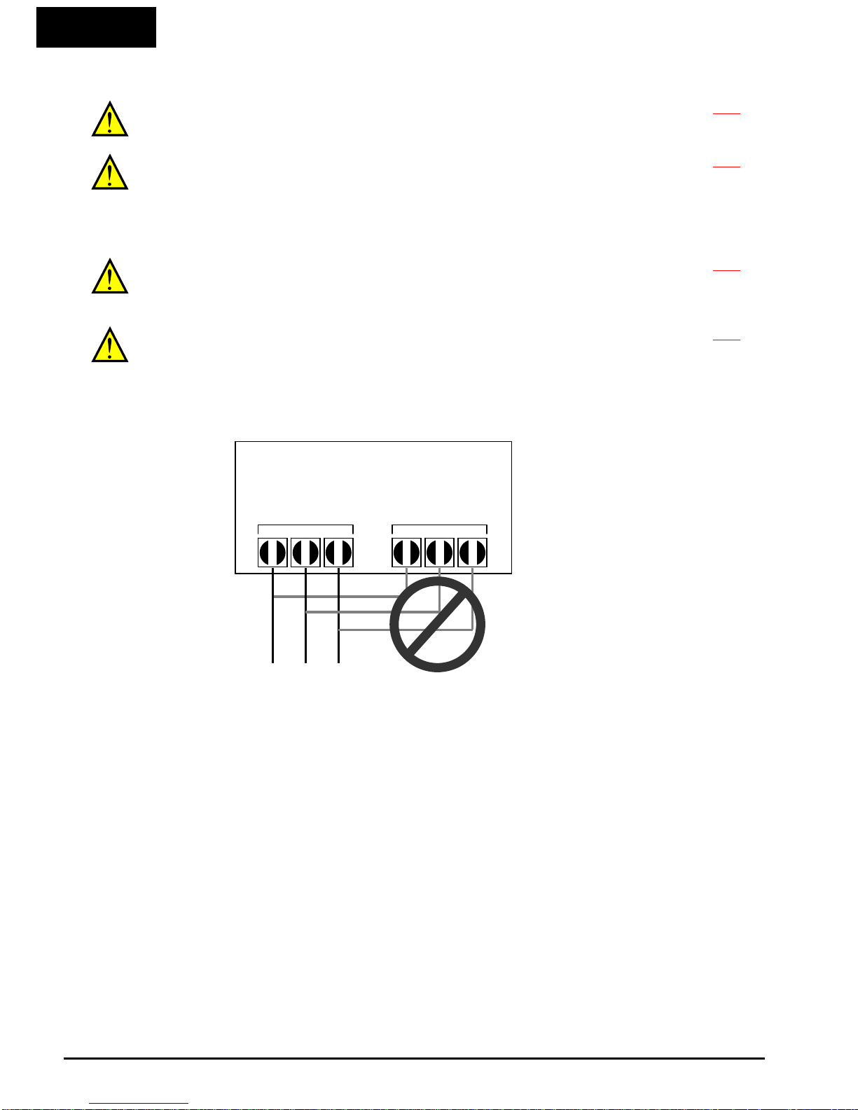
CAUTION: Be sure not to connect an AC power supply to the output terminals.
Otherwise, there is the possibility of damage to the inverter and the danger of
injury and/or fire.
… 2-20
Power Input
Output to Motor
WJ200 Inverter

vii
CAUTION: Remarks for using ground fault interrupter breakers in the main
power supply: Adjustable frequency inverter with integrated CE-filters and
shielded (screened) motor cables have a higher leakage current toward earth GND.
Especially at the moment of switching ON this can cause an inadvertent trip of
ground fault interrupters. Because of the rectifier on the input side of the inverter
there is the possibility to stall the switch-off function through small amounts of DC
current.
Please observe the following:
Use only short time-invariant and pulse current-sensitive ground fault
interrupters with higher trigger current.
Other components should be secured with separate ground fault interrupters.
Ground fault interrupters in the power input wiring of an inverter are not an
absolute protection against electric shock.
… 2-20
CAUTION: Be sure to install a fuse in each phase of the main power supply to the
inverter. Otherwise, there is the danger of fire.
… 2-20
CAUTION: For motor leads, ground fault interrupter breakers and
electromagnetic contactors, be sure to size these components properly (each must
have the capacity for rated current and voltage). Otherwise, there is the danger of
fire.
… 2-20
Powerup Test Caution Messages
CAUTION: The heat sink fins will have a high temperature. Be careful not to
touch them. Otherwise, there is the danger of getting burned.
… 2-23
CAUTION: The operation of the inverter can be easily changed from low speed to
high speed. Be sure to check the capability and limitations of the motor and
machine before operating the inverter. Otherwise, there is the danger of injury.
… 2-23
CAUTION: If you operate a motor at a frequency higher than the inverter
standard default setting (50Hz/60Hz), be sure to check the motor and machine
specifications with the respective manufacturer. Only operate the motor at
elevated frequencies after getting their approval. Otherwise, there is the danger of
equipment damage and/or injury.
… 2-23
… 2-29
CAUTION: Check the following before and during the Powerup test. Otherwise,
there is the danger of equipment damage.
Is the shorting bar between the [+1] and [+] terminals installed? DO NOT power
or operate the inverter if the jumper is removed.
Is the direction of the motor rotation correct?
Did the inverter trip during acceleration or deceleration?
Were the rpm and frequency meter readings as expected?
Were there any abnormal motor vibration or noise?
… 2-23

viii
Warnings for Configuring Drive Parameters
WARNIN G: When parameter b012, level of electronic thermal setting, is set to
motor FLA rating (Full Load Ampere nameplate rating), the inverter provides solid
state motor overload protection at 115% of motor FLA or equivalent. If parameter
B012 exceeds the motor FLA rating, the motor may overheat and damaged.
Parameter B012, level of electronic thermal setting, is a variable parameter.
… 3-34
Cautions for Configuring Drive Parameters
CAUTION: Be careful to avoid specifying a braking time that is long enough to
cause motor overheating. If you use DC braking, we recommend using a motor
with a built-in thermistor, and wiring it to the inverter’s thermistor input (see
“Thermistor Thermal Protection” on page 4-24). Also refer to the motor
manufacturer’s specifications for duty-cycle recommendations during DC braking.
… 3-19
HIGH VOLTAGE: When set RDY function ON, there will be a voltage appear at
motor output terminals U, V and W even if the motor is in stop mode. So never
touch the inverter power terminal even the motor is not running.
… 3-47
CAUTION: Do not change Debug mode for safety reasons. Otherwise unexpected
performances may occur.
… 3-62
Warnings for Operations and Monitoring
WARNIN G: Be sure to turn ON the input power supply only after closing the front
case. While the inverter is energized, be sure not to open the front case. Otherwise,
there is the danger of electric shock.
… 4-3
WARNIN G: Be sure not to operate electrical equipment with wet hands.
Otherwise, there is the danger of electric shock.
… 4-3
WARNIN G: While the inverter is energized, be sure not to touch the inverter
terminals even when the motor is stopped. Otherwise, there is the danger of
electric shock.
… 4-3
WARNIN G: If the retry mode is selected, the motor may suddenly restart after a
trip stop. Be sure to stop the inverter before approaching the machine (be sure to
design the machine so that safety for personnel is secure even if it restarts.)
Otherwise, it may cause injury to personnel.
… 4-3
WARNIN G: If the power supply is cut OFF for a short period of time, the inverter
may restart operating after the power supply recovers if the Run command is
active. If a restart may pose danger to personnel, so be sure to use a lock-out
circuit so that it will not restart after power recovery. Otherwise, it may cause
injury to personnel.
… 4-3
WARNIN G: The Stop Key is effective only when the stop function is enabled. Be
sure to enable the Stop Key separately from the emergency stop. Otherwise, it may
cause injury to personnel.
… 4-3
WARNIN G: During a trip event, if the alarm reset is applied and the Run
command is present, the inverter will automatically restart. Be sure to apply the
alarm reset only after verifying the Run command is OFF. Otherwise, it may cause
injury to personnel.
… 4-3

ix
WARNIN G: Be sure not to touch the inside of the energized inverter or to put any
conductive object into it. Otherwise, there is a danger of electric shock and/or fire.
… 4-3
WARNIN G: If power is turned ON when the Run command is already active, the
motor will automatically start and injury may result. Before turning ON the power,
confirm that the RUN command is not present.
… 4-3
… 4-3
WARNIN G: When the Stop key function is disabled, pressing the Stop key does not
stop the inverter, nor will it reset a trip alarm.
WARNIN G: Be sure to provide a separate, hard-wired emergency stop switch when
the application warrants it.
… 4-3
WARNIN G: If the power is turned ON and the Run command is already active, the
motor starts rotation and is dangerous! Before turning power ON, confirm that the
Run command is not active.
… 4-11
WARNIN G: After the Reset command is given and the alarm reset occurs, the motor
will restart suddenly if the Run command is already active. Be sure to set the alarm
reset after verifying that the Run command is OFF to prevent injury to personnel.
… 4-22
Cautions for Operations and Monitoring
CAUTION: The heat sink fins will have a high temperature. Be careful not to touch
them. Otherwise, there is the danger of getting burned.
… 4-2
CAUTION: The operation of the inverter can be easily changed from low speed to
high speed. Be sure to check the capability and limitations of the motor and
machine before operating the inverter. Otherwise, it may cause injury to personnel.
… 4-2
CAUTION: If you operate a motor at a frequency higher than the inverter standard
default setting (50Hz/60Hz), be sure to check the motor and machine specifications
with the respective manufacturer. Only operate the motor at elevated frequencies
after getting their approval. Otherwise, there is the danger of equipment damage.
… 4-2
CAUTION: It is possible to damage the inverter or other devices if your application
exceeds the maximum current or voltage characteristics of a connection point.
… 4-4
CAUTION: Be sure to turn OFF power to the inverter before changing the short
circuit bar position to change SR/SK. Otherwise, damage to the inverter circuitry
may occur.
… 4-8
CAUTION: Be careful not to turn PID clear ON and reset the integrator sum when
the inverter is in Run mode (output to motor is ON). Otherwise, this could cause the
motor to decelerate rapidly, resulting in a trip.
… 4-26
HIGH VOLTAGE: When set RDY function ON, there will be a voltage appear at
motor output terminals U, V and W even if the motor is in stop mode. So never
touch the inverter power terminal even the motor is not running.
… 4-31
CAUTION: The digital outputs (relay and/or open collector) available on the drive
must not be considered as safety related signals. The outputs of the external safety
relay must be used for integration into a safety related control/command circuit
… 4-32
HIGH VOLTAGE: Dangerous voltage exists even after the Safe Stop is activated.
It does
NOT
mean that the main power has been removed.
… 4-34

x
Warnings and Cautions for Troubleshooting and Maintenance
WARNIN G: Wait at least five (5) minutes after turning OFF the input power
supply before performing maintenance or an inspection. Otherwise, there is the
danger of electric shock.
… 6-2
WARNIN G: Make sure that only qualified personnel will perform maintenance,
inspection, and part replacement. Before starting to work, remove any metallic
objects from your person (wristwatch, bracelet, etc.). Be sure to use tools with
insulated handles. Otherwise, there is a danger of electric shock and/or injury to
personnel.
… 6-2
WARNIN G: Never remove connectors by pulling on its wire leads (wires for cooling
fan and logic P.C.board). Otherwise, there is a danger of fire due to wire breakage
and/or injury to personnel.
… 6-2
CAUTION: Do not connect the megger to any control terminals such as intelligent
I/O, analog terminals, etc. Doing so could cause damage to the inverter.
… 6-10
CAUTION: Never test the withstand voltage (HIPOT) on the inverter. The inverter
has a surge protector between the main circuit terminals above and the chassis
ground.
… 6-10
CAUTION: Do not connect the megger to any control circuit terminals such as
intelligent I/O, analog terminals, etc. Doing so could cause damage to the inverter.
… 6-10
CAUTION: Never test the withstand voltage (HIPOT) on the inverter. The inverter
has a surge protector between the main circuit terminals above and the chassis
ground.
… 6-10
HIGH VOLTAGE: Be careful not to touch wiring or connector terminals when
working with the inverters and taking measurements. Be sure to place the
measurement circuitry components above in an insulated housing before using
them.
… 6-14
General Warnings and Cautions iv
WARNIN G: Never modify the unit. Otherwise, there is a danger of electric shock and/or injury.
CAUTION: Withstand voltage test and insulation resistance tests (HIPOT) are executed before
the units are shipped, so there is no need to conduct these tests before operation.
CAUTION: Do not attach or remove wiring or connectors when power is applied. Also, do not
check signals during operation.
CAUTION: Be sure to connect the grounding terminal to earth ground.
CAUTION: When inspecting the unit, be sure to wait five minutes after turning OFF the power
supply before opening the cover.
xi
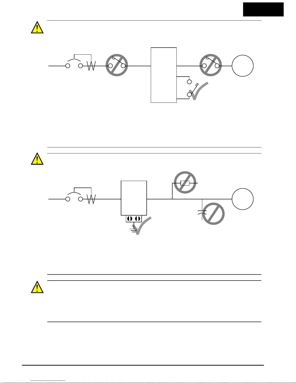
CAUTION: Do not stop operation by switching OFF electromagnetic contactors on the primary
or secondary side of the inverter.
When there has been a sudden power failure while an operation instruction is active, then the
unit may restart operation automatically after the power failure has ended. If there is a
possibility that such an occurrence may harm humans, then install an electromagnetic contactor
(Mgo) on the power supply side, so that the circuit does not allow automatic restarting after the
power supply recovers. If the optional remote operator is used and the retry function has been
selected, this will also cause automatic restarting when a Run command is active. So, please be
careful.
CAUTION: Do not insert leading power factor capacitors or surge absorbers between the output
terminals of the inverter and motor.
When there has been a sudden power failure while an operation instruction is active, then the
unit may restart operation automatically after the power failure has ended. If there is a
possibility that such an occurrence may harm humans, then install an electromagnetic contactor
(Mgo) on the power supply side, so that the circuit does not allow automatic restarting after the
power supply recovers. If the optional remote operator is used and the retry function has been
selected, this will also cause automatic restarting when a Run command is active. So, please be
careful.
Ground fault
interrupter
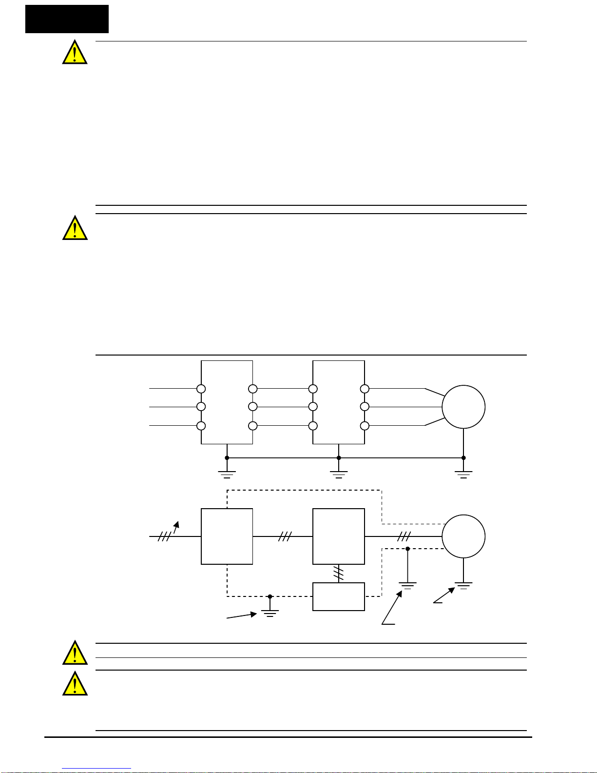
CAUTION: MOTOR TERMINAL SURGE VOLTAGE SUPPRESSION FILTER
(For the 400V CLASS)
In a system using an inverter with the voltage control PWM system, a voltage surge caused by
the cable constants such as the cable length (especially when the distance between the motor
and the inverter is 10m or more) and cabling method may occur at the motor terminals. A
dedicated filter of the 400V class for suppressing this voltage surge is available. Be sure to
install a filter in this situation.
Power
Input
Inverter
U, V, W
L1, L2, L3
Motor
PCS
FW
Power
Input
Ground fault
interrupter
L1, L2, L3
Inverter
U, V, W
Motor
Surge absorber
GND lug
Leading power
factor capacitor
xii
CAUTION: EFFECTS OF POWER DISTRIBUTION SYSTEM ON INVERTER
In the case below involving a general-purpose inverter, a large peak current can flow on the
power supply side, sometimes destroying the converter module:
1. The unbalance factor of the power supply is 3% or higher.
2. the power supply capacity is at least 10 times greater than the inverter capacity (or the
power supply capacity is 500kVA or more).
3. Abrupt power supply changes are expected, due to conditions such as:
a. Several inverters are interconnected with a short bus.
b. A thyristor converter and an inverter are interconnected with a short bus.
c. An installed phase advance capacitor opens and closes.
Where these conditions exist or when the connected equipment must be highly reliable, you
MUST install an input side AC-reactor of 3% (at a voltage drop at rated current) with respect to
the supply voltage on the power supply side. Also, where the effects of an indirect lightening
strike are possible, install a lightening conductor.
CAUTION: SUPPRESSION FOR NOISE INTERFERENCE FROM INVERTER
The inverter uses many semiconductor switching elements such as transistors and IGBTs. Thus,
a radio receiver or measuring instrument located near the inverter is susceptible to noise
interference.
To protect the instruments from erroneous operation due to noise interference, they should be
used well away from the inverter. It is also effective to shield the whole inverter structure.
The addition of an EMI filter on the input side of the inverter also reduces the effect of noise
from the commercial power line on external devices.
Note that the external dispersion of noise from the power line can be minimized by connecting
an EMI filter on the primary side of the inverter.
SFEF model has integrated filter complies to EN61800-3 category C1.
HFEF model has integrated filter complies to EN61800-3 category C2.
EMI Filter
CAUTION: When the EEPROM error E08 occurs, be sure to confirm the setting values again.
CAUTION: When using normally closed active state settings (C011 to C017) for externally
commanded Forward or Reverse terminals [FW] or [RV], the inverter may start automatically
when the external system is powered OFF or disconnected from the inverter! So do not use
normally closed active state settings for Forward or Reverse terminals [FW] or [RV] unless your
system design protects against unintended motor operation.
R1
S1
T1
R2
S2
T2
Inverter
L1
L2
L3
U
V
W
Motor
EMI Filter Inverter
Motor
Remote
Operator
Completely ground the
enclosure panel, metal
screen, etc. with as short
a wire as possible.
noise
Grounded frame
Conduit or shielded cable
-- to be grounded
xiii
CAUTION: In all the instrumentations in this manual, covers and safety devices are
occasionally removed to describe the details. While operating the product, make sure that the
covers and safety devices are placed as they were specified originally and operate it according to
the instruction manual.
CAUTION: Do not discard the inverter with household waste.
Contact an industrial waste management company in your area who can
treat industrial waste without polling the environment.
UL Cautions, Warnings and Instructions xii
Warnings and Cautions for Troubleshooting and Maintenance
The warnings and instructions in this section summarizes the procedures necessary to ensure
an inverter installation complies with Underwriters Laboratories
guidelines.
WARNIN G: Use 60/75C Cu wire only. (for models: WJ200-001L, -002L, -004L, -007L, -015S,
-022S, -004H, -007H, -015H, -022H and -030H)
WARNIN G: Use 75C Cu wire only. (for models: WJ200-001S, -002S, -004S, -007S, -015L, -022L,
-037L, -055L, -075L, -110L, -150L, -040H, -055H, -075H, -110H and -150H)
WARNIN G: Suitable for use on a circuit capable of delivering not more than 100,000 rms
Symmetrical Amperes, 240 or 480V maximum.
WARNIN G: When protected by CC, G, J, or R class Fuses, or when Protected By A Circuit
Breaker Having An Interrupting Rating Not Less Than 100,000 rms Symmetrical Amperes, 240
or 480 Volts Maximum.
WARNIN G: Install device in pollution degree 2 environment.
WARNIN G: Maximum Surrounding Air Temperature 50C
WARNIN G: Solid state motor overload protection is provided in each model
WARNIN G: Integral solid state short circuit protection does not provide branch circuit
protection. Branch circuit protection must be provided in accordance with the National Electric
Code and any additional local codes

xiv
Terminal symbols and Screw size
Inverter Model Screw Size
Required
Torque (N-m)
Wire range
WJ200-001S
WJ200-002S
WJ200-004S
M3.5 1.0 AWG16 (1.3mm
2
)
WJ200-007S M4 1.4 AWG12 (3.3mm2)
WJ200-015S
WJ200-022S
M4 1.4 AWG10 (5.3mm
2
)
WJ200-001L
WJ200-002L
WJ200-004L
WJ200-007L
M3.5 1.0 AWG16 (1.3mm
2
)
WJ200-015L M4 1.4 AWG14 (2.1mm2)
WJ200-022L M4 1.4 AWG12 (3.3mm2)
WJ200-037L M4 1.4 AWG10 (5.3mm2)
WJ200-055L
WJ200-075L
M5 3.0 AWG6 (13mm
2
)
WJ200-110L M6 5.9 to 8.8 AWG4 (21mm2)
WJ200-150L M8 5.9 to 8.8 AWG2 (34mm2)
WJ200-004H
WJ200-007H
WJ200-015H
M4 1.4 AWG16 (1.3mm
2
)
WJ200-022H
WJ200-030H
M4 1.4 AWG14 (2.1mm
2
)
WJ200-040H M4 1.4 AWG12 (3.3mm2)
WJ200-055H
WJ200-075H
M5 3.0 AWG10 (5.3mm
2
)
WJ200-110H
WJ200-150H
M6 5.9 to 8.8 AWG6 (13mm
2
)

xv
Fuse Sizes
The inverter shall be connected with a UL Listed Cartridge Nonrenewable fuse,
rated 600Vac with the current ratings as shown in the table below.
Inverter Model Type Rating
WJ200-001S
WJ200-002S
WJ200-004S
Class J
10A, AIC 200kA
WJ200-007S 15A, AIC 200kA
WJ200-015S
WJ200-022S
30A, AIC 200kA
WJ200-001L
WJ200-002L
WJ200-004L
10A, AIC 200kA
WJ200-007L
WJ200-015L
15A, AIC 200kA
WJ200-022L 20A, AIC 200kA
WJ200-037L 30A, AIC 200kA
WJ200-055L
WJ200-075L
40A, AIC 200kA
WJ200-110L
WJ200-150L
80A, AIC 200kA
WJ200-004H
WJ200-007H
WJ200-015H
WJ200-022H
10A, AIC 200kA
WJ200-030H
WJ200-040H
15A, AIC 200kA
WJ200-055H
WJ200-075H
20A, AIC 200kA
WJ200-110H
WJ200-150H
40A, AIC 200kA

xvi
Table of Contents
Safety Messages
Hazardous High Voltage ............................................................................................................... i
General Precautions – Read These First! ................................................................................. ii
Index to Warnings and Cautions in This Manual .................................................................... iv
General Warnings and Cautions ................................................................................................. x
UL Cautions, Warnings and Instructions .............................................................................. xiii
Circuit Breaker and Fuse Sizes ................................................................................................ xv
Table of Contents
Revisions ............................................................................................................................... xviii
Contact Information ............................................................................................................... xix
Chapter 1: Getting Started
Introduction ............................................................................................................................ 1-2
WJ200 Inverter Specifications .............................................................................................. 1-4
Introduction to Variable-Frequency Drives ........................................................................ 1-18
Frequently Asked Questions ............................................................................................... 1-23
Chapter 2: Inverter Mounting and Installation
Orientation to Inverter Features .......................................................................................... 2-2
Basic System Description ...................................................................................................... 2-4
Step-by-Step Basic Installation ............................................................................................ 2-6
Powerup Test ........................................................................................................................ 2-23
Using the Front Panel Keypad ........................................................................................... 2-25
Chapter 3: Configuring Drive Parameters
Choosing a Programmable Device ........................................................................................ 3-2
Using the Keypad Devices ..................................................................................................... 3-3
“D” Group: Monitoring Functions ......................................................................................... 3-7
“F” Group: Main Profile Parameters ................................................................................... 3-11
“A” Group: Standard Functions .......................................................................................... 3-12
“B” Group: Fine Tuning Functions ..................................................................................... 3-44
“C” Group: Intelligent Terminal Functions ........................................................................ 3-83
“H” Group: Motor Constants Functions ........................................................................... 3-104
“P” Group: Other Parameters ............................................................................................ 3-111

xvii
Chapter 4: Operations and Monitoring
Introduction ............................................................................................................................ 4-2
Connecting to PLCs and Other Devices ............................................................................... 4-4
Control Logic Signal Specifications ...................................................................................... 4-6
Intelligent Terminal Listing ................................................................................................ 4-10
Using Intelligent Input Terminals ...................................................................................... 4-12
Using Intelligent Output Terminals ................................................................................... 4-51
Analog Input Operation ....................................................................................................... 4-87
Pulse Train Input Operation ............................................................................................... 4-89
Analog Output Operation ...................................................................................................... 4-90
Chapter 5: Inverter System Accessories
Introduction ............................................................................................................................ 5-2
Component Description ......................................................................................................... 5-3
Chapter 6: Troubleshooting and Maintenance
Troubleshooting ...................................................................................................................... 6-2
Monitoring Trip Events, History, & Conditions ................................................................... 6-8
Restoring Factory Default Settings .................................................................................... 6-14
Maintenance and Inspection ............................................................................................... 6-15
Warranty ............................................................................................................................... 6-22
Appendix A: Glossary and Bibliography
Glossary .................................................................................................................................. A-2
Bibliography ........................................................................................................................... A-8
Appendix B: ModBus Network Communications
Introduction ............................................................................................................................ B-2
Connecting the Inverter to ModBus ..................................................................................... B-3
Network Protocol Reference .................................................................................................. B-5
ModBus Data Listing ........................................................................................................... B-24
Appendix C: Drive parameter Setting Tables
Introduction ............................................................................................................................ C-2
Parameter Settings for Keypad Entry .................................................................................. C-2
Appendix D: EMC installation guidance
Appendix E: Safety

xviii
Revisions
Revision History Table
No. Revision Comments
Date of
Issue
Operation
Manual No.

xix
Contact Information
Hitachi Australia Ltd.
Hitachi America, Ltd.
Level 3, 82 Waterloo Road
Power and Industrial Division
North Ryde, N.S.W. 2113
50 Prospect Avenue
Australia
Tarrytown, NY 10591
Phone: +61-2-9888-4100
U.S.A.
Fax: +61-2-9888-4188
Phone: +1-914-631-0600
Fax: +1-914-631-3672
Hitachi Industrial Equipment Systems Co., Ltd.
Hitachi Europe GmbH
AKS Building, 3, kanda Neribei-cho
Am Seestern 18
Chiyoda-ku, Tokyo, 101-0022
D-40547 Dusseldorf
Japan
Germany
Phone: +81-3-4345-6910
Phone: +49-211-5283-0
Fax: +81-3-4345-6067
Fax: +49-211-5283-649
Hitachi Industrial Equipment Systems Co., Ltd.
Hitachi Asia Ltd.
Narashino Division
16 Collyer Quay
1-1, Higashi-Narashino 7-chome
#20-00 hitachi Tower, Singapore 049318
Narashino-shi, Chiba 275-8611
Singapore
Japan
Phone: +65-538-6511
Phone: +81-47-474-9921
Fax: +65-538-9011
Fax: +81-47-476-9517
Hitachi Asia (Hong Kong) Ltd.
7th Floor, North Tower
World Finance Centre, Harbour City
Canton Road, Tsimshatsui, Kowloon
Hong Kong
Phone: +852-2735-9218
Fax: +852-2735-6793
NOTE: To receive technical support for the Hitachi inverter you purchased, contact the
Hitachi inverter dealer from whom you purchased the unit, or the sales office or
factory contact listed above. Please be prepared to provide the following inverter
nameplate information:
1. Model
2. Date of purchase
3. Manufacturing number (MFG No.)
4. Symptoms of any inverter problem
If any inverter nameplate information is illegible, please provide your Hitachi contact
with any other legible nameplate items. To reduce unpredictable downtime, we
recommend that you stock a spare inverter.

1−1
1
Getting Started
In This Chapter… page
- Introduction ...................................................................................... 2
- WJ200 Inverter Specifications ........................................................ 4
- Introduction to Variable-Frequency Drives .................................. 18
- Frequently Asked Questions ........................................................ 23

1−2
Introduction
Main Features
Congratulation on your purchase of an WJ200 Series Hitachi inverter! This inverter
drive features state-of-the-art circuitry and components to provide high performance.
The housing footprint is exceptionally small, given the size of the corresponding motor.
The Hitachi WJ200 product line includes more than a dozen inverter models to cover
motor sizes from 1/8 horsepower to 20 horsepower, in either 240VAC or 480VAC power
input versions.
The main features are:
• 200V and 400V class, 0.1 to 15kW inverters having dual rating
• US or EU versions available
• EzSQ (simple programming function) integrated
• Built-in RS485 MODBUS RTU as standard, other FieldBus optional
• New current suppressing function
• Sixteen programmable speed levels
• PID control adjusts motor speed automatically to maintain a process variable value
• Password protection to avoid unexpected parameter change
The design in Hitachi inverters overcomes many of the traditional trade-offs between
speed, torque and efficiency. The performance characteristics are:
• High starting torque of 200% at 0.5Hz
• Continuous operation at 100% torque within a 1:10 speed range (6/60Hz / 5/50Hz)
without motor derating.
• Fan has ON/OFF selection to provide longer life for cooling fan.
A full line of accessories from Hitachi is available to complete your motor application:
• Integrated USB port for PC communication
• Digital remote operator keypad
• Integrated brake chopper
• EMC filter (footprint type C1) optional

1−3
Inverter Specification Label
The Hitachi WJ200 inverters have product labels located on the right side of the
housing, as pictured below. Be sure to verify that the specifications on the labels match
your power source, and application safety requirements.
Inverter Specification Label
The model number for a specific inverter contains useful information about its
operating characteristics. Refer to the model number legend below:
WJ200
001 S F
Series name
Configuration type
F=with keypad
Input voltage:
S=Single-phase 200V class
L=Three-phase 200V class
H=Three-phase 400V class
A
pplicable motor capacity in kW
001=0.1kW 037=3.7kW
002=0.2kW 040=4.0kW
004=0.4kW 055=5.5kW
007=0.75kW 075=7.5kW
015=1.5kW 110=11kW
022=2.2kW 150=15kW
030=3.0kW
200 -240
200
-240
2.0/1.3
1.2 /1. 0
1005
05A _T1 2345
_
A _
-001
-001SF
Model name
Input ratings
Output ratings
Ver:2.0
MFG number

1−4
WJ200 Inverter Specifications
Model-specific tables for 200V and 400V class inverters
The following tables are specific to WJ200 inverters for the 200V and 400V class model
groups. Note that “General Specifications” on page in this chapter
apply to both voltage
class groups. Footnotes for all specification tables follow the table below.
Item Single-phase 200V class Specifications
WJ200 inverters, 200V models 001SF 002SF 004SF 007SF 015SF 022SF
Applicable motor size
*2
kW VT 0.2 0.4 0.55 1.1 2.2 3.0
CT 0.1 0.2 0.4 0.75 1.5 2.2
HP VT 1/4 1/2 3/4 1.5 3 4
CT 1/8 1/4 1/2 1 2 3
Rated capacity (kVA) 200V VT 0.4 0.6 1.2 2.0 3.3 4.1
CT 0.2 0.5 1.0 1.7 2.7 3.8
240V VT 0.4 0.7 1.4 2.4 3.9 4.9
CT 0.3 0.6 1.2 2.0 3.3 4.5
Rated input voltage
Single-phase: 200V-15% to 240V +10%, 50/60Hz ±5%
Rated output voltage *3 3-phase: 200 to 240V (proportional to input voltage)
Rated output current (A) VT 1.2 1.9 3.5 6.0 9.6 12.0
CT 1.0 1.6 3.0 5.0 8.0 11.0
Starting torque *6 200% at 0.5Hz
Braking Without resistor
100%:
≤
50Hz
50%:
≤
60Hz
70%: 50Hz
≤
50%: 60Hz
≤
20%: 50Hz
≤
20%:
≤
60Hz
With resistor 150% 100%
DC braking Variable operating frequency, time, and braking force
Weight kg 1.0 1.0 1.1 1.6 1.8 1.8
lb 2.2 2.2 2.4 3.1 4.0 4.0

1−5
Footnotes for the preceding table and the tables that follow:
Note1: The protection method conforms to JEM 1030.
Note2: The applicable motor refers to Hitachi standard 3-phase motor (4p). When
using other motors, care must be taken to prevent the rated motor current
(50/60Hz) from exceeding the rated output current of the inverter.
Note3: The output voltage decreases as the main supply voltage decreases (except
when using the AVR function). In any case, the output voltage cannot exceed
the input power supply voltage.
Note4: To operate the motor beyond 50/60Hz, consult the motor manufacturer for
the maximum allowable rotation speed.
Note5: For achieving approved input voltage rating categories:
• 460 to 480VAC – Over-voltage category 2
• 380 to 460VAC – Over-voltage category 3
To meet the Over-voltage category 3, insert an EN or IEC standard
compliant isolation transformer that is earth grounded and star connected
(for Low Voltage Directive).
Note6: At the rated voltage when using a Hitachi standard 3-phase, 4-pole motor.
Note7: The braking torque via capacitive feedback is the average deceleration
torque at the shortest deceleration (stopping from 50/60Hz as indicated). It is
not continuous regenerative braking torque. The average deceleration torque
varies with motor loss. This value decreases when operating beyond 50Hz. If
a large regenerative torque is required, the optional regenerative braking
unit and a resistor should be used.
Note8: The frequency command is the maximum frequency at 9.8V for input voltage
0 to 10VDC, or at 19.6mA for input current 4 to 20mA. If this characteristic
is not satisfactory for your application, contact your Hitachi representative.
Note9: If the inverter is operated outside the region shown in the graph in the
derating curve, the inverter may be damaged or its service life may be
shortened. Set Β083 Carrier Frequency Adjustment in accordance with the
expected output current level. See derating curve section for the detailed
information of the inverter operating range.
Note10: The storage temperature refers to the short-term temperature during
transportation.
Note11: Conforms to the test method specified in JIS JIS C 60068-2-6 :2010(IEC
60068-2-6:2007). For the model types excluded in the standard specifications,
contact your Hitachi sales representative.
Note12: Watt losses are calculated values based on specification of main
semi-conductors. You must take suitable margin when designing cabinet
based on these values. Otherwise there is a possibility of heating trouble.

1−6
WJ200 Inverter Specifications, continued…
Item Three-phase 200V class Specifications
WJ200 inverters, 200V models
001LF 002LF 004LF 007LF 015LF 022LF
Applicable motor size
*2
kW V T 0.2 0.4 0.75 1.1 2.2 3.0
CT 0.1 0.2 0.4 0.75 1.5 2.2
HP VT 1/4 1/2 1 1.5 3 4
CT 1/8 1/4 1/2 1 2 3
Rated capacity (kVA) 200V VT 0.4 0.6 1.2 2.0 3.3 4.1
CT 0.2 0.5 1.0 1.7 2.7 3.8
240V VT 0.4 0.7 1.4 2.4 3.9 4.9
CT 0.3 0.6 1.2 2.0 3.3 4.5
Rated input voltage
Three-phase: 200V-15% to 240V +10%, 50/60Hz ±5%
Rated output voltage *3 Three-phase: 200 to 240V (proportional to input voltage)
Rate d o utput c u rr ent (A) VT 1.2 1.9 3.5 6.0 9.6 12.0
CT 1.0 1.6 3.0 5.0 8.0 11.0
Starting torque *6 200% at 0.5Hz
Braking Without resistor
100%:
≤
50Hz
50%:
≤
60Hz
70%: 50Hz
≤
50%: 60Hz
≤
With resistor 150%
DC braking Variable operating frequency, time, and braking force
Weight kg 1.0 1.0 1.1 1.2 1.6 1.8
lb 2.2 2.2 2.4 2.6 3.5 4.0
Item Three-phase 200V class Specifications
WJ200 inverters, 200V models
037LF 055LF 075LF 110LF 150LF
Applicable motor size
*2
kW VT 5.5 7.5 11 15 18.5
CT 3.7 5.5 7.5 11 15
HP VT 7.5 10 15 20 25
CT 5 7.5 10 15 20
Rated capacity (kVA) 200V VT 6.7 10.3 13.8 19.3 20.7
CT 6.0 8.6 11.4 16.2 20.7
240V VT 8.1 12.4 16.6 23.2 24.9
CT 7.2 10.3 13.7 19.5 24.9
Rated input voltage
Three-phase: 200V-15% to 240V +10%, 50/60Hz ±5%
Rated output voltage *3 Three-phase: 200 to 240V (proportional to input voltage)
Rated output current (A) VT 19.6 30.0 40.0 56.0 69.0
CT 17.5 25.0 33.0 47.0 60.0
Starting torque *6 200% at 0.5Hz
Braking Without resistor
100%:
≤
50Hz
50%:
≤
60Hz
70%: 50Hz
≤
50%: 60Hz
≤
With resistor 150%
DC braking Variable operating frequency, time, and braking force
Weight Kg 2.0 3.3 3.4 5.1 7.4
lb 4.4 7.3 7.5 11.2 16.3

1−7
WJ200 Inverter Specifications, continued…
Item Three-phase 400V class Specifications
WJ200 inverters, 400V models
004HF 007HF 015HF 022HF 030HF 040HF
Applicable motor size
*2
kW V T 0.75 1.5 2.2 3.0 4.0 5.5
CT 0.4 0.75 1.5 2.2 3.0 4.0
HP VT 1 2 3 4 5 7.5
CT 1/2 1 2 3 4 5
Rated capacity (kVA) 380V VT 1.3 2.6 3.5 4.5 5.7 7.3
CT 1.1 2.2 3.1 3.6 4.7 6.0
480V VT 1.7 3.4 4.4 5.7 7.3 9.2
CT 1.4 2.8 3.9 4.5 5.9 7.6
Rated input voltage
Three-phase: 400V-15% to 480V +10%, 50/60Hz ±5%
Rated output voltage *3 Three-phase: 400 to 480V (proportional to input voltage)
Rate d o utput c u rr ent (A) VT 2.1 4.1 5.4 6.9 8.8 11.1
CT 1.8 3.4 4.8 5.5 7.2 9.2
Starting torque *6 200% at 0.5Hz
Braking Without resistor
100%:
≤
50Hz
50%:
≤
60Hz
70%: 50Hz
≤
50%: 60Hz
≤
With resistor 150%
DC braking Variable operating frequency, time, and braking force
Weight kg 1.5 1.6 1.8 1.9 1.9 2.1
lb 3.3 3.5 4.0 4.2 4.2 4.6
Item Three-phase 400V class Specifications
WJ200 inverters, 400V models
055HF 075HF 110HF 150HF
Applicable motor size
*2
kW V T 7.5 11 15 18.5
CT 5.5 7.5 11 15
HP VT 10 15 20 25
CT 7.5 10 15 20
Rated capacity (kVA) 380V VT 11.5 15.1 20.4 25.0
CT 9.7 11.8 15.7 20.4
480V VT 14.5 19.1 25.7 31.5
CT 12.3 14.9 19.9 25.7
Rated input voltage
Three-phase: 400V-15% to 480V +10%, 50/60Hz ±5%
Rated output voltage *3 Three-phase: 400 to 480V (proportional to input voltage)
Rated output current (A) VT
17.5 23.0 31.0 38.0
CT
14.8 18.0 24.0 31.0
Starting torque *6 200% at 0.5Hz
Braking Without resistor
100%:
≤
50Hz
50%:
≤
60Hz
With resistor 150%
DC braking Variable operating frequency, time, and braking force
Weight kg 3.5 3.5 4.7 5.2
lb 7.7 7.7 10.4 11.5

1−8
General Specifications
The following table applies to all WJ200 inverters.
Item General Specifications
Protective housing *1
IP20
Control method
Sinusoidal Pulse Width Modulation (PWM) control
Carrier frequency
2kHz to 15kHz (derating required depending on the model)
Output frequency range *4
0.1 to 400Hz
Frequency accuracy
Digital command: ±0.01% of the maximum frequency
Analog command: ±0.2% of the maximum frequency (25°C ± 10°C)
Frequency setting resolution
Digital: 0.01Hz; Analog: max. frequency/1000
Volt./Freq. characteristic
V/f control (constant torque, reduced torque, free-V/F): base freq.
30Hz~400Hz adjustable,
Sensorless vector control, Closed loop control with motor encoder feedback
Overload capacity
Dual rating: CT(Heavy duty) : 60 sec. @150%
VT(Normal duty) : 60 sec. @120%
Acceleration/deceleration time
0.01 to 3600 seconds, linear and S-curve accel/decel, second accel/decel
setting available
Starting torque
200% @0.5Hz (sensorless vector control)
Input
signal
Freq.
setting
Operator panel
Up and Down keys / Value settings
External signal
*8
0 to 10 VDC (input impedance 10k Ohms), 4 to 20mA (input impedance 100
Ohms), Potentiometer (1k to 2k Ohms, 2W)
Via network
RS485 ModBus RTU, other network option
FWD/
REV run
Operator panel
Run/Stop (Forward/Reverse run change by command)
External signal
Forward run/stop, Reverse run/stop
Via network
RS485 ModBus RTU, other network option
Intelligent input
terminal
Seven terminals,
sink/source changeable
by a short bar
68 functions assignable
FW (forward run command), RV (reverse run command), CF1~CF4
(multi-stage speed setting), JG (jog command), DB (external braking), SET
(set second motor), 2CH (2-stage accel./decel. command), FRS (free run stop
command), EXT (external trip), USP (startup function), CS (commercial
power switchover), SFT (soft lock), AT (analog input selection), RS (reset),
PTC (thermistor thermal protection), STA (start), STP (stop), F/R
(forward/reverse), PID (PID disable), PIDC (PID reset), UP (remote control
up function), DWN (remote control down function), UDC (remote control
data clear), OPE (operator control), SF1~SF7 (multi-stage speed setting; bit
operation), OLR (overload restriction), TL (torque limit enable), TRQ1
(torque limit changeover1), TRQ2 (torque limit changeover2), BOK (Braking
confirmation), LAC (LAD cancellation), PCLR (position deviation clear),
ADD (add frequency enable), F-TM (force terminal mode), ATR (permission
of torque command input), KHC (Cumulative power clear), MI1~MI7
(general purpose inputs for EzSQ), AHD (analog command hold), CP1~CP3
(multistage-position switches), ORL (limit signal of zero-return), ORC
(trigger signal of zero-return), SPD (speed/position changeover), GS1,GS2
(STO inputs, safety related signals), 485 (Starting communication signal),
PRG (executing EzSQ program), HLD (retain output frequency), ROK
(permission of run command), EB (rotation direction detection of B-phase),
DISP (display limitation), NO (no function)

1−9
Item General Specifications
Output
signal
Intelligent output
terminal
48 functions assignable
RUN (run signal), FA1~FA5 (frequency arrival signal), OL,OL2 (overload
advance notice signal), OD (PID deviation error signal), AL (alarm signal),
OTQ (over/under torque threshold), UV (under-voltage), TRQ (torque limit
signal), RNT (run time expired), ONT (power ON time expired), THM
(thermal warning), BRK (brake release), BER (brake error), ZS (0Hz
detection), DSE (speed deviation excessive), POK (positioning completion),
ODc (analog voltage input disconnection), OIDc (analog current input
disconnection), FBV (PID second stage output), NDc (network disconnect
detection), LOG1~LOG3 (Logic output signals), WAC (capacitor life
warning), WA F (cooling fan warning), FR (starting contact), OHF (heat sink
overheat warning), LOC (Low load), MO1~MO3 (general outputs for EzSQ),
IRDY (inverter ready), FWR (forward operation), RVR (reverse operation),
MJA (major failure), WCO (window comparator O), WCOI (window
comparator OI), FREF (frequency command source), REF (run command
source), SETM (second motor in operation), EDM (STO (safe torque off)
performance monitor), OP (option control signal), NO (no function)
Monitor output (analog)
Output freq., output current, output torque, output voltage, input power,
thermal load ratio, LAD freq., heat sink temperature, general output (EzSQ)
Pulse train output
(0~10Vdc, 32kHz max.)
[PWM output]
Output freq., output current, output torque, output voltage, input power,
thermal load ratio, LAD freq., heat sink temperature, general output (EzSQ)
[Pulse train output]
Output frequency, output current, pulse train input monitor
Alarm output contact
ON for inverter alarm (1c contacts, both normally open or closed available.)
Other functions
Free-V/f, manual/automatic torque boost, output voltage gain adjustment,
AVR function, reduced voltage start, motor data selection, auto-tuning,
motor stabilization control, reverse running protection, simple position
control, simple torque control, torque limiting, automatic carrier frequency
reduction, energy saving operation, PID function, non-stop operation at
instantaneous power failure, brake control, DC injection braking, dynamic
braking (BRD), frequency upper and lower limiters, jump frequencies, curve
accel and decel (S, U, inversed U,EL-S), 16-stage speed profile, fine
adjustment of start frequency, accel and decel stop, process jogging,
frequency calculation, frequency addition, 2-stage accel/decel, stop mode
selection, start/end freq., analog input filter, window comparators, input
terminal response time, output signal delay/hold function, rotation direction
restriction, stop key selection, software lock, safe stop function, scaling
function, display restriction, password function, user parameter,
initialization, initial display selection, cooling fan control, warning, trip
retry, frequency pull-in restart, frequency matching, overload restriction,
over current restriction, DC bus voltage AVR
Protective function
Over-current, over-voltage, under-voltage, overload, brake resistor overload,
CPU error, memory error, external trip, USP error, ground fault detection at
power on, temperature error, internal communication error, driver error,
thermistor error, brake error, safe stop, overload at low speed, modbus
communication error, option error, encoder disconnection, speed excessive,
EzSQ command error, EzSQ nesting error, EzSQ execution error, EzSQ user
trip
Operating
environment
Temperature
Operating (ambient): -10 to 40°C(*10), / Storage: -20 to 65°C(*11)
Humidity
20 to 90% humidity (non-condensing)
Vibration *11
5.9m/s2 (0.6G), 10 to 55 Hz
Location
Altitude 1,000m or less, indoors (no corrosive gasses or dust)
Coating color
Black
Options
Remote operator unit, cables for the units, braking unit, braking resistor, AC
reactor, DC reactor, EMC filter, fieldbus

1−10
Signal Ratings
Detailed ratings are in “Control Logic Signal Specifications” in chapter 4.
Signal / Contact Ratings
Built-in power for inputs 24VDC, 100mA maximum
Discrete logic inputs 27VDC maximum
Discrete logic outputs 50mA maximum ON state current, 27 VDC maximum OFF state voltage
Analog output 10bit / 0 to 10VDC, 2mA
Analog input, current 4 to 19.6 mA range, 20mA nominal
Analog input, voltage
0 to 9.8 VDC range, 10VDC nominal, input impedance 10kΩ
+10V analog reference 10VDC nominal, 10mA maximum
Alarm relay contacts 250 VAC, 2.5A (R load) max., 0.2A (I load, P.F.=0.4) max.
100 VAC, 10mA min
30 VDC, 3.0A (R load) max., 0.7A (I load, P.F.=0.4) max.)
5 VDC, 100mA min.
1−11
Derating Curves
The maximum available inverter current output is limited by the carrier frequency and
ambient temperature.. Choosing a higher carrier frequency tends to decrease audible
noise, but it also increases the internal heating of the inverter, thus decreasing
(derating) the maximum current output capability. Ambient temperature is the
temperature just outside the inverter housing⎯such as inside the control cabinet
where the inverter is mounted. A higher ambient temperature decreases (derates) the
inverter’s maximum current output capacity.
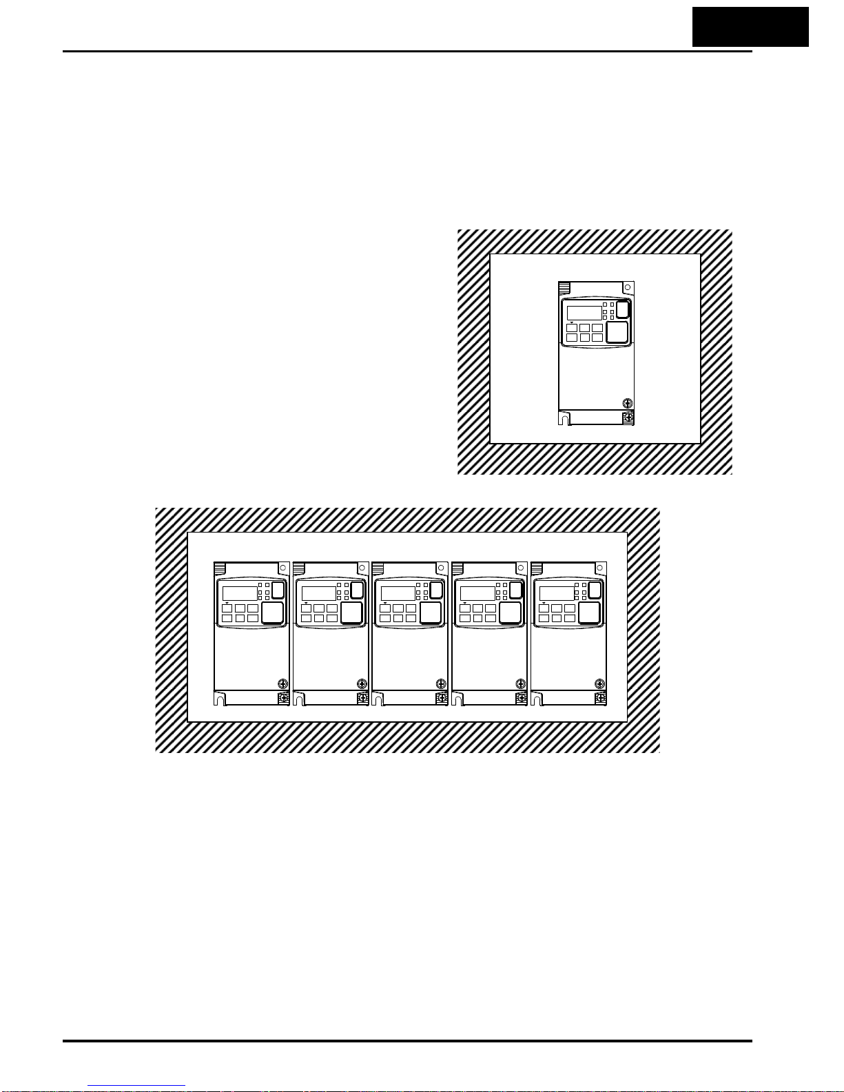
Individual mounting
An inverter may be mounted individually
in an enclosure or side-by-side with other
inverter(s) as shown below. Side-by-side
mounting causes greater derating than
mounting inverters separately. Graphs for
either mounting methods are included in
this section. Refer to “Ensure Adequate
Ventilation” on page 2-10 for minimum
clearance dimensions for both mounting
configurations.
Enclosure
Side-by-side mounting
Enclosure

1−12
The following table shows which models need derating.
1-ph 200V class Need
derating
3-ph 200V class Need
derating
3-ph 400V class Need
derating
WJ200-001S
- -
WJ200-001L
WJ200-004H
9
WJ200-002S
-
WJ200-002L
9
WJ200-007H
9
WJ200-004S
9
WJ200-004L
9
WJ200-015H
-
WJ200-007S
9
WJ200-007L
- -
WJ200-022H
WJ200-015S
- - -
WJ200-015L
WJ200-030H
WJ200-022S
- -
WJ200-022L
WJ200-040H
9
- - -
WJ200-037L
9
WJ200-055H
- - -
WJ200-055L
WJ200-075H
9
- -
WJ200-075L
9
WJ200-110H
9
- -
WJ200-110L
9
WJ200-150H
9
- - - -
WJ200-150L
9
9:need derating
-:need no derating
Use the following derating curves to help determine the optimal carrier frequency
setting for your inverter and find the output current derating. Be sure to use the
proper curve for your particular WJ200 inverter model number.
Legend for Graphs:
Ambient temperature 40℃ max., individual mounting
Ambient temperature 50℃ max., individual mounting
Ambient temperature 40℃ max., side-by-side mounting
Derating curves:
Models need no derating
2 4 6 8 10 12 16kH140
100%
80%
60%
40%
20%
HD
Carrier frequency
2 4 6 8 10 12 0
100%
80%
60%
40%
20%
14kH
ND
Carrier frequency
% of rated
output current

1−13
Derating curves, continued...
Models need derating
WJ200-002L
WJ200-004L
246 81012 16 140
HD(1.6A)
Carrier frequency (kHz)
1.5
2.0
1.0
2 4 6 8 10 12 14 0
Carrier frequency (kHz)
1.5
1.0
2.0
40℃ individual
40℃
side-by-side
40℃ individual
40℃
side-by-side
ND(1.9A)
Output
current (A)
WJ200-004S
246 81012 16 140
1.0
HD(3.0A)
Carrier frequency (kHz)
2.0
2 4 6 8 10 12 14 0
ND(3.5A)
Carrier frequency (kHz)
3.0
3.0
1.0
2.0
3.6
3.6
Output
current (A)
246 81012 16 140
1.0
HD(3.0A)
Carrier frequency (kHz)
2.0
2 4 6 8 10 12 14 0
ND(3.5A)
Carrier frequency (kHz)
3.0
3.0
1.0
2.0
3.6
3.6
40℃ indivi
40℃
side-by-side
dual
40℃ individual
40℃
side-by-side
50℃ individual
Output
current (A)

1−14
Derating curves, continued...
WJ200-004H
246 81012 16 140
HD(1.8A)
2 4 6 8 10 12 14 0
1.5
1.0
2.0
2.2
ND(2.1A)
40℃ individual
40℃
side-by-side
50℃ individual
40℃
individual
40℃
side-by-side
2.2
2.0
Output
current (A)
1.5
1.0
Carrier frequency (kHz)
Carrier frequency (kHz)
246 81012 16
4.0
140
4.0
HD(5.0A)
5.0
6.0
40℃ individual
40℃
side-by-side
6.6
ND(6.0A)
WJ200-007S
2 4 6 8 10 12 14 0
40℃ individual
40℃
side-by-side
Carrier frequency (kHz)
6.6
6.0
Output
current (A)
5.0
Carrier frequency (kHz)
246 8101216140
2.0
(3.4A)
Carrier frequency (kHz)
3.0
HD
2 4 6 8 10 12 14 0
ND 4.1A)
Carrier fre
(
q
uency (kHz)
4.0
WJ200 H-007
4.4
4.4
2.0
3.0
4.0
Output
current (A)
40℃ individual
40℃
side-by-side

1−15
Derating curves, continued...
rrier frequency (kHCa
z)
Carrier frequency (kHz)
246 81012 16 140
HD(17.5A)
2 4 6 8 10 12 14 0
ND(19.6A)
WJ200-037L
20
19
18
17
16
15
14
19
18
17
16
15
14
20
Output
current (A)
2
46 81012 16 140
HD(9.2A)
Carrier frequency (kHz)
2 4 6 8 10 12 14 0
ND(11.1A)
Carrier frequency (kHz)
WJ200-040H
12
11
10
9
8
7
6
11
10
9
8
7
6
12
40℃ individual
40℃
side-by-side
40℃ individual
40℃
side-by-side
Output
current (A)
WJ200
246 81012 16 140
HD(33.0A)
Carrier frequency (kHz)
2468 10 12 14 0
ND(40.0A)
Carrier frequency (kHz)
-075L
42
40
38
36
34
32
30
40
38
36
34
32
30
42
40℃ individual
40℃
side-by-side
Output
current (A)
40℃ individual
40℃
side-by-side
50℃ individual

1−16
Derating curves, continued...
WJ200-110L
WJ200-075H
246 81012 16140
HD(18.0A)
Carrier fre
q
uency (kHz)
2468 10 12 14 0
ND(23.0A)
Carrier frequency (kHz)
26
24
22
20
18
16
14
24
22
20
18
16
14
26
40℃ indivi
50℃
indivi
Output
current
dual
dual
(A)
40℃ individual
40℃
side-by-side
50℃ individual
W
J200-110H
246 81012 16 140
HD(24.0A)
Carrier frequency (kHz)
2 4 6 8 10 12 14 0
ND(31.0A)
Carrier frequency (kHz)
32
30
28
26
24
22
20
30
28
26
24
22
20
32
50℃ individual
40℃
side-by-side
Output
current (A)
40℃ individual
40℃
side-by-side
50℃ individual
246 81012 16 140
HD(47.0A)
Carrier frequency (kHz)
2468 10 12 14 0
ND(56.0A)
Carrier frequency (kHz)
60
55
50
45
40
35
30
55
50
45
40
35
30
60
40℃ individual
40℃
side-by-side
Output
current (A)

1−17
Derating curves, continued...
WJ200-150L
WJ200-150H
2 4 6 8 10 12 16kH140
HD(60.0A)
Carrier frequency (kHz)
2 4 6 8 10 12 14 0
ND(69.0A)
Carrier frequency (kHz)
75
70
65
60
55
50
45
70
65
60
55
50
45
75
50℃ individual
40℃
side-by-side
50℃ individual
40℃
side-by-side
Output
current (A)
246 81012 16 140
HD(31.0A)
Carrier frequency (kHz)
2 4 6 8 10 12 14 0
ND(38.0A)
Carrier frequency (kHz)
40
35
30
25
20
15
10
35
30
25
20
15
10
40
50℃ individual
40℃
side-by-side
Output
current (A)
50℃ individual
40℃
side-by-side

1−18
Introduction to Variable-Frequency Drives
The Purpose of Motor Speed Control for Industry
Hitachi inverters provide speed control for 3-phase AC induction motors. You connect
AC power to the inverter, and connect the inverter to the motor. Many applications
benefit from a motor with variable speed, in several ways:
• Energy savings – HVAC
• Need to coordinate speed with an adjacent process – textile and printing presses
• Need to control acceleration and deceleration (torque)
• Sensitive loads – elevators, food processing, pharmaceuticals
What is an Inverter
The term
inverter
and
variable-frequency drive
are related and somewhat
interchangeable. An electronic motor drive for an AC motor can control the motor’s
speed by
varying the frequency
of the power sent to the motor.
An inverter, in general, is a device that converts DC power to AC power. The figure
below shows how the variable-frequency drive employs an internal inverter. The drive
first converts incoming AC power to DC through a rectifier bridge, creating an internal
DC bus voltage. Then the inverter circuit converts the DC back to AC again to power
the motor. The special inverter can vary its output frequency and voltage according to
the desired motor speed.
Rectifier
Motor
Inverter Converter Internal
DC Bus
Power
Input
R/L1
S/L2
T/L3
U/T1
V/T2
W/T3
Variable-frequency Drive
The simplified drawing of the inverter shows three double-throw switches. In Hitachi
inverters, the switches are actually IGBTs (insulated gate bipolar transistors). Using a
commutation algorithm, the microprocessor in the drive switches the IGBTs on and off
at a very high speed to create the desired output waveforms. The inductance of the
motor windings helps smooth out the pulses.

1−19
Torque and Constant Volts/Hertz Operation
Output
voltage
In the past, AC variable speed drives used
an open loop (scalar) technique to control
speed. The constant-volts-hertz operation
maintains a constant ratio between the
applied voltage and the applied frequency.
With these conditions, AC induction motors
inherently delivered constant torque across
the operating speed range. For some
applications, this scalar technique was
adequate.
V
Today, with the advent of sophisticated microprocessors and digital signal processors
(DSPs), it is possible to control the speed and torque of AC induction motors with
unprecedented accuracy. The WJ200 utilizes these devices to perform complex
mathematical calculations required to achieve superior performance. You can choose
various torque curves to fit the needs of your application. Constant torque applies the
same torque level across the frequency (speed) range.
Variab l e torque
, also called
reduced torque
, lowers the torque delivered at mid-level frequencies. A torque boost
setting will add additional torque in the lower half of the frequency range for the
constant and variable torque curves. With the
free-setting torque
curve feature, you
can specify a series of data points that will define a custom torque curve to fit your
application.
Inverter Input and Three-phase Power
The Hitachi WJ200 Series of inverters includes two sub-groups: the 200V class and the
400V class inverters. The drive described in this manual may be used in either the
United States or Europe, although the exact voltage level for commercial power may be
slightly different from country to country. Accordingly, a 200V class inverter requires
(nominal) 200 to 240VAC, and 400V class inverter requires from 380 to 480VAC.
The 200V class inverters having a suffix of –SF accept single-phase 200V class input
voltage, those with a suffix –LF three-phase power only. All 400V class inverters
require three-phase power supply.
TIP: If your application only has single phase power available, refer to WJ200 inverter
of 3HP or less (European version with a suffix of -SFE); they can accept single phase
input power. Note: Larger models may be able to accept single-phase with derating.
Contact your Hitachi distributor for assistance.
The common terminology for single phase power is line (L) and Neutral (N).
Three-phase power connections are usually labeled Line 1 [R/L1], Line 2 [S/L2] and
Line 3 [T/L3]. In any case, the power source should include an earth ground connection.
That ground connection will need to connect to the inverter chassis and to the motor
frame (see “Wire the Inverter Output to Motor” on page 2-21).
0
Output frequency
100%
f
Constant torque

1−20
Inverter Output to the Motor
3-phase AC motor
The AC motor must be connected only to the inverter’s
output terminals. The output terminals are uniquely
labeled (to differentiate them from the input terminals)
with the designations U/T1, V/T2, and W/T3. This
corresponds to typical motor lead connection designations
T1, T2, and T3. It is often not necessary to connect a
particular motor lead for a new application. The
consequence of swapping any two of the three connections
is the reversal of the motor direction. In applications where
reversed rotation could cause equipment damage or
personnel injury, be sure to verify direction of rotation
before attempting full-speed operation.
U/T1
V/T2
W/T3
Earth GND
For safety to personnel, you must connect the motor chassis ground to the ground
connection at the bottom of the inverter housing.
Notice the three connections to the motor do not include one marked “Neutral” or
“Return”. The motor represents a balanced “Y” impedance to the inverter, so there is no
need for a separate return. In other words, each of the three “Hot” connections serves
also as a return for the other connections, because of their phase relationship.
The Hitachi inverter is a rugged and reliable device. The intention is for the inverter to
assume the role of controlling power to the motor during all normal operations.
Therefore, this manual instructs you not to switch off power to the inverter
while the
motor is running
(unless it is an emergency stop). Also, do not install or use disconnect
switches in the wiring from the inverter to the motor (except thermal disconnect). Of
course, safety-related devices such as fuses must be in the design to break power
during a malfunction, as required by NEC and local codes.

1−21
Intelligent Functions and Parameters
Much of this manual is devoted to describing how to use inverter functions and how to
configure inverter parameters. The inverter is micro-processor-controlled, and has
many independent functions. The microprocessor has an on-board EEPROM for
parameter storage. The inverter’s front panel keypad provides access to all functions
and parameters, which you can access through other devices as well. The general name
for all these devices is the
digital operator, integrated operator,
or
digital operator
panel
. Chapter 2 will show you how to get a motor running, using a minimal set of
function commands or configuring parameters.
The optional read/write programmer will let you read and write inverter EEPROM
contents from the programmer. This feature is particularly useful for OEMs who need
to duplicate a particular inverter’s settings in many other inverters in assembly-line
fashion.
Braking
In general, braking is a force that attempts to slow or stop motor rotation. So it is
associated with motor deceleration, but may also occur even when the load attempts to
drive the motor faster than the desired speed (overhauling). If you need the motor and
load to decelerate quicker than their natural deceleration during coasting, we
recommend installing a braking resistor. The dynamic braking unit (built into WJ200)
sends excess motor energy into a resistor to slow the motor and load (See
“Introduction” on page 5-2 and “Dynamic Braking” on page 5-5 for more information).
For loads that continuously overhaul the motor for extended periods of time, the
WJ200 may not be suitable (contact your Hitachi distributor).
The inverter parameters include acceleration and deceleration, which you can set to
match the needs of the application. For a particular inverter, motor, and load, there will
be a range of practically achievable accelerations and decelerations.
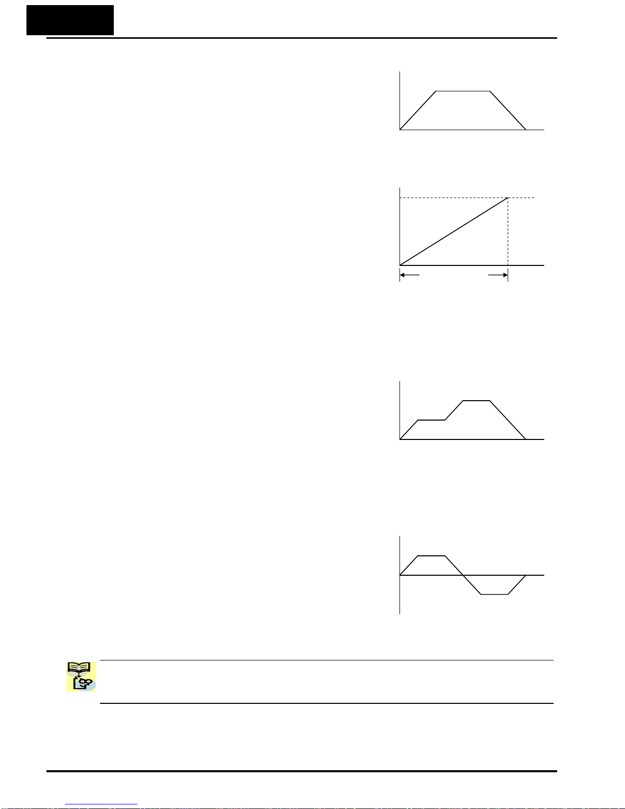
1−22
Velocity Profiles
The WJ200 inverter is capable of sophisticated
speed control. A graphical representation of that
capability will help you understand and
configure the associated parameters. This
manual makes use of the velocity profile graph
used in industry (shown at right). In the
example,
acceleration
is a ramp to a set speed,
and
deceleration
is a decline to a stop.
Speed
Acceleration and deceleration settings specify
the time required to go from a stop to maximum
frequency (or vise versa). The resulting slope
(speed change divided by time) is the
acceleration or deceleration. An increase in
output frequency uses the acceleration slope,
while a decrease uses the deceleration slope.
The accel or decel time a particular speed
change depends on the starting and ending
frequencies.
However, the slope is constant, corresponding to the full-scale accel or decel time
setting. For example, the full-scale acceleration setting (time) may be 10 seconds – the
time required to go from 0 to 60Hz.
The WJ200 inverter can store up to 16 preset
speeds. And, it can apply separate acceleration
and deceleration transitions from any preset to
any other preset speed. A multi-speed profile
(shown at right) uses two or more preset speeds,
which you can select via intelligent input
terminals. This external control can apply any
preset speed at any time.
Alternatively, the selected speed is infinitely variable across the speed range. You can
use the potentiometer control on the keypad for manual control. The drive accepts
analog 0-10VDC signals and 4-20 mA control signals as well.
The inverter can drive the motor in either
direction. Separate FW and RV commands
select the direction of rotation. The motion
profile example shows a forward motion
followed by a reverse motion of shorter duration.
The speed presets and analog signals control
the magnitude of the speed, while the FWD and
REV commands determine the direction before
the motion starts.
NOTE: The WJ200 can move loads in both directions. However, it is not designed for
use in servo-type applications that use a bipolar velocity signal that determines
direction.
0
Velocity Profile
t
A
ccel Decel
Set speed
Speed
0
t
Maximum speed
Acceleration
(time setting)
Speed
0
Multi-speed Profile
t
Speed 1
Speed 2
Speed
0
Bi-directional Profile
t
Forward move
Reverse move

1−23
Frequently Asked Questions
Q. What is the main advantage in using an inverter to drive a motor, compared to
alternative solutions?
A. An inverter can vary the motor speed with very little loss of efficiency, unlike
mechanical or hydraulic speed control solutions. The resulting energy savings
usually pays for the inverter in a relatively short time.
Q. The term “inverter” is a little confusing, since we also use “drive” and “amplifier” to
describe the electronic unit that controls a motor. What does “inverter” mean?
A. The term
inverter, drive,
and
amplifier
are used somewhat interchangeably in
industry. Nowadays, the term
drive, variable-frequency drive, variable-speed
drive
, and
inverter
are generally used to describe electronic,
microprocessor-based motor speed controllers. In the past,
variable-speed
drive
also referred to various mechanical means to vary speed.
Amplifier
is a
term almost exclusively used to describe drives for servo or stepper motors.
Q. Although the WJ200 inverter is a variable speed drive, can I use it in a fixed-speed
application?
A. Yes, sometimes an inverter can be used simply as a “soft-start” device,
providing controlled acceleration and deceleration to a fixed speed. Other
functions of the WJ200 may be useful in such applications, as well. However,
using a variable speed drive can benefit many types of industrial and
commercial motor applications, by providing controlled acceleration and
deceleration, high torque at low speeds, and energy savings over alternative
solutions.
Q. Can I use an inverter and AC induction motor in a positioning application?
A. That depends on the required precision, and the slowest speed the motor must
turn and still deliver torque. The WJ200 inverter will deliver full torque while
turning the motor at 6Hz (180RPM). DO NOT use an inverter if you need the
motor to stop and hold the load position without the aid of a mechanical brake
(use a servo or stepper motion control system).
Q. Can the inverter be controlled and monitored via a network?
A. Yes. WJ200 inverters have built-in ModBus communications. See Appendix B
for more information on network communications.
Q. Why does the manual or other documentation use terminology such as “200V class”
instead of naming the actual voltage, such as “230 VAC”
A. A specific inverter model is set at the factory to work across a voltage range
particular to the destination country for that model. The model specifications
are on the label on the side of the inverter. A European 200V class inverter
(“EU” marking) has different parameter settings than a USA 200V class.
NOTE: The European 200V class inverter is for single phase input (-SFE), while the
USA 200V class inverter is for 3 phase input (-LFU).

1−24
Q. Why doesn’t the motor have a neutral connection as a return to the inverter?
A. The motor theoretically represents a “balanced Y” load if all three stator
windings have the same impedance. The Y connection allows each of the three
wires to alternatively serve as input or return on alternate half-cycle.
Q. Does the motor need a chassis ground connection?
A. Yes, for several reasons. Most importantly, this provides protection in the
event of a short in the motor that puts a hazardous voltage on its housing.
Secondly, motors exhibit leakage current that increase with aging. Lastly, a
grounded chassis generally emits less electrical noise than an ungrounded
one.
Q. What type of motor is compatible with the Hitachi inverters?
A. Motor type – It must be a three-phase AC induction motor. Use an
inverter-grade motor that has at least 800V insulation for 200V class inverters,
or 1600V insulation for 400V class.
Motor size – In practice, it’s better to find the right size motor for your
application; then look for the inverter to match the motor.
NOTE: There may be other factors that will affect motor selection, including heat
dissipation, motor operating speed profile, enclosure type, and cooling method.
Q. How many poles should the motor have?
A. Hitachi inverters can be configured to operate motors with 2, 4, 6, or 8 poles.
The greater the number of the poles, the slower the top motor speed will be,
but it will have higher torque at the base speed.
Q. Will I be able to add dynamic (resistive) braking to my Hitachi WJ200 drive after
the initial installation?
A. Yes, the WJ200 inverter already has a dynamic braking circuit built in. Just
add the resistor sized to meet the braking requirements. For more information,
contact your nearest Hitachi representative.

1−25
Q. How will I know if my application will require resistive braking?
A. For new applications, it may be difficult to tell before you actually test a
motor/drive solution. In general, some application can rely on system losses
such as friction to serve as the deceleration force, or otherwise can tolerate a
long decel time. These applications will not need dynamic braking.
However, applications with a combination of a high-inertia load and a required
short decel time will need dynamic braking. This is a physics question that
may be answered either empirically or through extensive calculations.
Q. Several options related to electrical noise suppression are available for the Hitachi
inverters. How can I know if my application require any of these options?
A. The purpose of these noise filters is to reduce the inverter electrical noise so
the operation of nearby electrical devices is not affected. Some applications are
governed by particular regulatory agencies, and noise suppression is
mandatory . in those cases, the inverter must have the corresponding noise
filter installed. Other applications may not need noise suppression, unless you
notice electrical interference with the operation of other devices.
Q. The WJ200 features a PID control. PID loops are usually associated with chemical
processes, heating, or process industries in general. How could the PID loop
feature be useful in my application?
A. You will need to determine the particular main variable in your application
the motor affects. That is the process variable (PV) for the motor. Over time, a
faster motor speed will cause a faster change in the PV than a slow motor
speed will. By using the PID loop feature, the inverter commands the motor to
run at the optimal speed required to maintain the PV at the desired value for
current conditions. Using the PID loop feature will require an additional
sensor and other wiring, and is considered an advanced application.

2−1
2
Inverter Mounting
and Installation
In This Chapter… page
- Orientation to Inverter Features ..................................................... 2
- Basic System Description ............................................................... 4
- Step-by-Step Basic Installation ...................................................... 6
- Powerup Test .................................................................................. 23
- Using the Front Panel Keypad ...................................................... 25

2−2
Orientation to Inverter Features
Unpacking and Inspection
Please take a few moments to unpack your new WJ200 inverter and perform these
steps:
1. Look for any damage that may have occurred during transportation.
2. Verify the contents of the box include:
a. One WJ200 inverter
b. One instruction Manual
c. One WJ200 Quick Reference Guide
3. Inspect the specifications label on the side of the inverter. Make sure it matches
the product part number you ordered.
Main Physical Features
The WJ200 Series inverters vary in size according
to the current output rating and motor size for each
model number. All feature the same basic Keypad
and connector interface for consistent ease of use.
The inverter construction has a heat sink at the
back of the housing. The larger models include a fan
to enhance heat sink performance. The mounting
holes are predrilled in the heat sink for your
convenience. Smaller models have two mounting
holes, while larger ones have four. Be sure to use all
the mounting holes provided.
Never touch the heat sink during or just after
operation; it can be very hot.
The electronics housing and front panel are built
onto the front of the heat sink.
Inverter Keypad – The inverter uses a digital
operator interface, or keypad. The four-digit display
can show a variety of performance parameters.
LEDs indicate whether the display units are Hertz
or Amperes. Other LEDs indicate Power (external),
and Run/Stop mode and Program/Monitor Mode
status. Membrane keys Run and Stop/Reset control
monitor operation. The ESC, SET, U and V keys
allow an operator to navigate to the inverter’s
functions and parameter values. The SET key is
used when changing a parameter.

2−3
Power Wiring Access – First, ensure no power source is connected to the inverter. If
power has been connected, verify that the Power LED is OFF and then wait five
minutes after power down to proceed. After removing the terminal cover and front
housing cover, the housing partitions that cover the power and motor wiring exits will
be able to slide upward as shown below.
Notice the four wire exit slots in the housing partition. This helps keep the power and
motor wiring (to the left) separated from the signal-level logic or analog wiring (to the
right).
Remove the housing partition and as shown as set them aside in a secure place while
wiring. Be sure to replace them afterward. Never operate the inverter with the
partition removed or the front housing cover removed.
The power input and motor 3-phase wiring connect to the lower row of the terminals.
The upper row of power terminals connect to optional braking units or DC link choke.
The following section in this chapter will describe system design and guide you through
a step-by-step installation process. After the section on wiring, this chapter will show
how to use the front panel keys to access functions and edit parameters.
Terminal cover
Front cover
Housing partition
NOTE: The h
ousing partition can be removed without removing the front cover in
the following models.
Single-phase 200V: 0.7 to 2.2kW
Three-phase 200V: 1.5 to 15kW
Three-phase 400V: All size

2−4
Basic System Description
A motor control system will obviously include a motor and inverter, as well as a circuit
breaker or fuses for safety. If you are connecting a motor to the inverter on a test bench
just to get started, that’s all you may need for now. But a system can also have a
variety of additional components. Some can be for noise suppression, while others may
enhance the inverter’s braking performance. The figure and table below show a system
with all the optional components you might need in your finished application.
Name Function
Breaker /
disconnect
A molded-case circuit breaker (MCCB), ground fault
interrupter (GFI), or a fused disconnect device. NOTE:
The installer must refer to the NEC and local codes to
ensure safety and compliance.
Input-side
AC Reactor
This is useful in suppressing harmonics induced on the
power supply lines and for improving the power factor.
WARNIN G: Some applications must use an input-side
AC Reactor to prevent inverter damage. See Warning
on next page.
Radio noise
filter
Electrical noise interference may occur on nearby
equipment such as a radio receiver. This magnetic
choke filter helps reduce radiated noise (can also be
used on output).
EMC filter (for
CE applications,
see Appendix D)
Reduces the conducted noise on the power supply
wiring between the inverter and the power distribution
system. Connect to the inverter primary (input) side.
Radio noise
filter (use in
non-CE
applications)
This capacitive filter reduces radiated noise from the
main power wires in the inverter input side.
DC link choke
Suppress harmonics generated by the inverter.
However, it will not protect the input diode bridge
rectifier.
Radio noise
filter
Electrical noise interference may occur on nearby
equipment such as a radio receiver. This magnetic
choke filter helps reduce radiated noise (can also be
used on input).
Output-side
AC Reactor
This reactor reduces the vibration in the motor caused
by the inverter’s switching waveforms, by smoothing
the waveform to approximate commercial power quality.
It is also useful to reduce harmonics when wiring from
the inverter to the motor is more than 10m in length.
LCR filter
Sine wave shaping filter for output side.
NOTE: Note that some components are required for regulatory agency compliance (see
chapter 5 and Appendix D).
Breaker,
MCCB or
GFI
From power supply
L1 L2 L3
T1 T2 T3
Inverter
+1
+
GND
Motor
Thermal
switch

2−5
WARNING: In the cases below involving a general-purpose inverter, a large peak
current can flow on the power supply side, sometimes destroying the converter module:
1. The unbalance factor of the power supply is 3% or higher.
2. The power supply capacity is at least 10 times greater than the inverter capacity
(or the power supply capacity is 500kVA or more).
3. Abrupt power supply changes are expected, due to conditions such as:
a. Several inverters are interconnected with a short bus.
b. A thyristor converter and an inverter are interconnected with a short bus.
c. An installed phase advance capacitor opens and closes.
Where these conditions exist or when the connected equipment must be highly reliable,
you MUST install an input-side AC reactor of 3% (at a voltage drop at rated current)
with respect to the supply voltage on the power supply side. Also, where the effects of
an indirect lightning strike are possible, install a lightning conductor.

2−6
Step-by-S tep Basic Installation
This section will guide you through the following basic steps of installation:
Step Activity Page
1 Choose a mounting location in compliance with the Warnings and Cautions.
See NOTE below.
2 Check the mounting location for adequate ventilation
3 Cover the inverter’s ventilation openings to prevent debris from entering.
4 Check the inverter dimensions for footprint and mounting hole locations.
5 Study the Cautions, Warnings, wire and fuse sizes, and terminal torque
specifications before wiring the inverter.
6 Connect wiring for the inverter power input.
7 Wire the inverter output to the motor.
8 Uncover the inverter’s ventilation openings applied in Step 3.
9 Perform the Powerup Test. (This step includes several sub steps.)
10 Make observations and check your installation.
NOTE: If the installation is in an EU country, study the EMC installation guidelines in
Appendix D.

2−7
Choosing a Mounting Location
Step 1: Study the following caution messages associated with mounting the inverter.
This is the time when mistakes are most likely to occur that will result in expensive
rework, equipment damage, or personal injury.
1
CAUTION: Be sure to install the unit on flame-resistant material such as steel plate.
Otherwise, there is the danger of fire.
CAUTION: Be sure not to place any flammable materials near the inverter. Otherwise,
there is the danger of fire.
CAUTION: Be sure not to let the foreign matter enter vent openings in the inverter
housing, such as wire clippings, spatter from welding, metal shavings, dust, etc.
Otherwise, there is the danger of fire.
CAUTION: Be sure to install the inverter in a place that can bear the weight according
to the specifications in the text (Chapter 1, Specifications Tables). Otherwise, it may
fall and cause injury to personnel.
CAUTION: Be sure to install the unit on a perpendicular wall that is not subject to
vibration. Otherwise, it may fall and cause injury to personnel.
CAUTION: Be sure not to install or operate an inverter that is damaged or has missing
parts. Otherwise, it may cause injury to personnel.
CAUTION: Be sure to install the inverter in a well-ventilated room that does not have
direct exposure to sunlight, a tendency for high temperature, high humidity or dew
condensation, high levels of dust, corrosive gas, explosive gas, inflammable gas,
grinding-fluid mist, salt damage, etc. Otherwise, there is the danger of fire.

2−8
Ensure Adequate Ventilation
Step 2: To summarize the caution messages – you will need to find a solid,
non-flammable, vertical surface that is in a relatively clean and dry environment. In
order to ensure enough room for air circulation around the inverter to aid in cooling, it
is recommended to maintain the specified clearance and the inverter specified in the
below diagram.
2
10 cm (3.94”)
CAUTION: Be sure to maintain the specified clearance area around the inverter and to
provide adequate ventilation. Otherwise, the inverter may overheat and cause
equipment damage or fire.
Keep Debris Out of Inverter Vents
Step 3: Before proceeding to the wiring section, it’s
a good time to
temporarily
covers the inverter’s
ventilation openings. Paper and masking tape are
all that is needed. This will prevent harmful debris
such as wire clippings and metal shavings from
entering the inverter during installation.
Please observe this checklist while mounting the
inverter:
1. The ambient temperature must be in the range
of −10 to 40°C.
2. Keep any other heat-producing equipment as
far away from the inverter as possible.
3. When installing the inverter in an enclosure, maintain the clearance around the
inverter and verify that its ambient is within specification when the enclosure door
is closed.
4. Do not remove the front housing at any time during operation.
3
A
ir flow
minimum
10 cm (3.94”)
minimum
5 cm (1.97”)
minimum
5 cm (1.97”)
minimum
Clear area
WJ200
inverter
Ventilation holes (top)
Ventilation holes
(both sides)

2−9
Check Inverter Dimensions
Step 4: Locate the applicable drawing on the following pages for your inverter.
Dimensions are given in millimeters (inches) format.
Power Type W (mm) H (mm) D (mm) D1 (mm)
Single-phase 200V WJ200-001SF
WJ200-002SF
68 128
109 13.5
WJ200-004SF 122.5 27
3-phase 200V WJ200-001LF
WJ200-002LF
109 13.5
WJ200-004LF 122.5 27
WJ200-007LF 145.5 50
NOTE: Some inverter housing require two mounting screws, while other requires four.
Be sure to use lock washers or other means to ensure screws do not loosen due to
vibration.
4

2−10
Dimensional drawings, continued…
Power Type W (mm) H (mm) D (mm) D1 (mm)
Single-phase 200V WJ200-007SF
108 128
170.5 55
WJ200-015SF
WJ200-022SF
3-phase 200V WJ200-015LF
WJ200-022LF
3-phase 400V WJ200-004HF
143.5 28
WJ200-007HF
WJ200-015HF
WJ200-022HF
WJ200-030HF
170.5 55

2−11
Dimensional drawings, continued…
Power Type W (mm) H (mm) D (mm) D1 (mm)
3-phase 200V WJ200-037LF
140 128 170.5 55
3-phase 400V WJ200-040HF

2−12
Dimensional drawings, continued…
Power Type W (mm) H (mm) D (mm) D1 (mm)
3-phase 200V WJ200-055LF
WJ200-075LF
140 260 155 73.3
3-phase 400V WJ200-055HF
WJ200-075HF
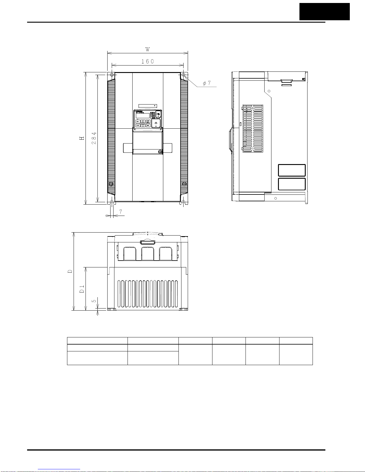
2−13
Dimensional drawings, continued…
Power Type W (mm) H (mm) D (mm) D1 (mm)
3-phase 200V WJ200-110LF
180 296 175 97
3-phase 400V WJ200-110HF
WJ200-150HF
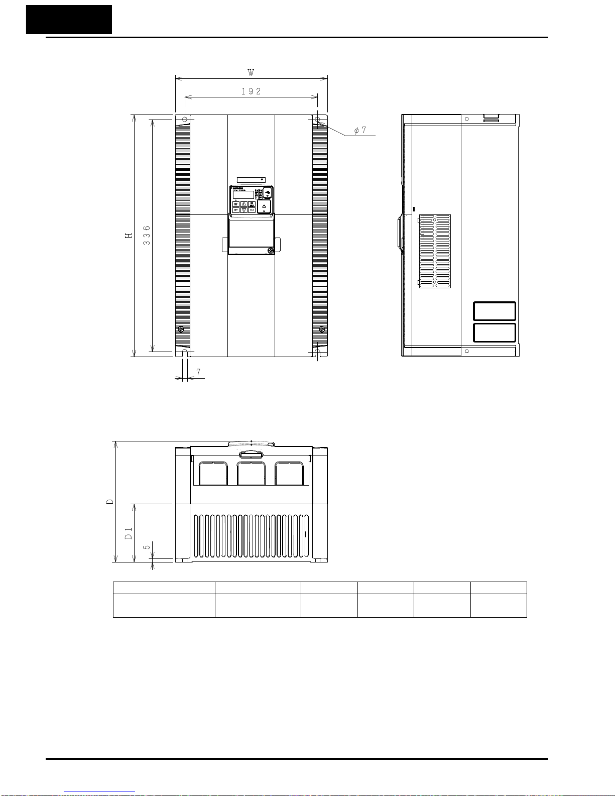
2−14
Dimensional drawings, continued…
Power Type W (mm) H (mm) D (mm) D1 (mm)
3-phase 200V WJ200-150LF 220 350 175 84

2−15
Prepare for Wiring
Step 5: It is very important to perform the wiring steps carefully and correctly. Before
proceeding, please study the caution and warning message herebelow.
5
WARNING: Use 60/75°C Cu wire only. (for models: WJ200-001L, -002L, -004L, -007L,
-015S, -022S, -004H, -007H, -015H, -022H and -030H)
WARNING: Use 75°C Cu wire only. (for models: WJ200-001S, -002S, -004S, -007S,
-015L, -022L, -037L, -055L, -075L, -110L, -150L, -040H, -055H, -075H,
-110H and -150H)
WARNING: “USE 60°C Cu wire only” or equivalent. For models WJ200-004H, -007H,
and –015H.
WARNING: “Open Type Equipment.”
WARNING: “Suitable for use on a circuit capable of delivering not more than 100k rms
symmetrical amperes, 240V maximum.” For models with suffix S or L.
WARNING: “Suitable for use on a circuit capable of delivering not more than 100k rms
symmetrical amperes, 480V maximum.” For models with suffix H.
HIGH VOLTAGE: Be sure to ground the unit. Otherwise, there is a danger of electric
shock and/or fire.
HIGH VOLTAGE: Wiring work shall be carried out only by qualified personnel.
Otherwise, there is a danger of electric shock and/or fire.
HIGH VOLTAGE: Implement wiring after checking that the power supply is OFF.
Otherwise, you may incur electric shock and/or fire.
HIGH VOLTAGE: Do not connect wiring to an inverter or operate an inverter that is
not mounted according to the instructions given in this manual. Otherwise, there is a
danger of electric shock and/or injury to personnel.

2−16
Determining Wire and Fuse Sizes
The maximum motor currents in your application determines the recommended wore
size. The following table gives the wire size in AWG. The “Power Lines” column applies
to the inverter input power, output wires to the motor, the earth ground connection,
and any other components shown in the “Basic System Description” on page 2-4. The
“Signal Lines” column applies to any wire connecting to the two green connectors just
inside the front cover panel.
Motor Output
Inverter Model
Wiring
A
pplicable
equipment
kW HP
Power Lines
Signal
Lines
Fuse (UL-rated,
class J, 600V)
V
T CT VT CT
0.2 0.1 ¼ 1/8
WJ200-001SF
AWG16 / 1.3mm
2
(75°C only)
18 to 28
AWG / 0.14
to 0.75 mm
2
shielded wire
(see Note 4)
10A
0.4 0.2 ½ ¼
WJ200-002SF
0.55
0.4 ¾ ½
WJ200-004SF
1.1
0.75
1.5 1
WJ200-007SF
AWG12 / 3.3mm
2
(75°C only)
15A
2.2 1.5 3 2
WJ200-015SF
AWG10 / 5.3mm
2
30A
3.0 2.2 4 3
WJ200-022SF
0.2 0.1 ¼ 1/8
WJ200-001LF
AWG16 / 1.3mm
2
10A
0.4 0.2 ½ ¼
WJ200-002LF
0.75
0.4 1 ½
WJ200-004LF
1.1
0.75
1.5 1
WJ200-007LF
15A
2.2 1.5 3 2
WJ200-015LF
AWG14 / 2.1mm
2
(75°C only)
3.0 2.2 4 3
WJ200-022LF
AWG12 / 3.3mm
2
(75°C only)
20A
5.5 3.7 7.5 5
WJ200-037LF
AWG10 / 5.3mm
2
(75°C only)
30A
7.5 5.5 10 7.5
WJ200-055LF
AWG6 / 13mm
2
(75°C only)
40A
11 7.5 15 10
WJ200-075LF
15 11 20 15
WJ200-110LF
AWG4 / 21mm
2
(75°C only)
80A
18.5
15 25 20
WJ200-150LF
AWG2 / 34mm
2
(75°C only)
80A
0.75
0.4 1 ½
WJ200-004HF
AWG16 / 1.3mm
2
10A
1.5
0.75
2 1
WJ200-007HF
2.2 1.5 3 2
WJ200-015HF
3.0 2.2 4 3
WJ200-022HF
AWG14 / 2.1mm2
4.0 3.0 5 4
WJ200-030HF
15A
5.5 4.0 7.5 5
WJ200-040HF
AWG12 / 3.3mm
2
(75°C only)
7.5 5.5 10 7.5
WJ200-055HF
AWG10 / 5.3mm
2
(75°C only)
20A
11 7.5 15 10
WJ200-075HF
15 11 20 15
WJ200-110HF
AWG6 / 13mm
2
(75°C only)
40A
18.5
15 25 20
WJ200-150HF
AWG6 / 13mm
2
(75°C only)
40A
Note 1: Field wiring must be made by a UL-Listed and CSA-certified closed-loop
terminal connector sized for the wire gauge involved. Connector must be fixed
by using the crimping tool specified by the connector manufacturer.
Note 2: Be sure to consider the capacity of the circuit breaker to be used.
Note 3: Be sure to use a larger wire gauge if power line length exceeds 66ft. (20m).
Note 4: Use 18 AWG / 0.75mm
2
wire for the alarm signal wire ([AL0], [AL1], [AL2]
terminals).
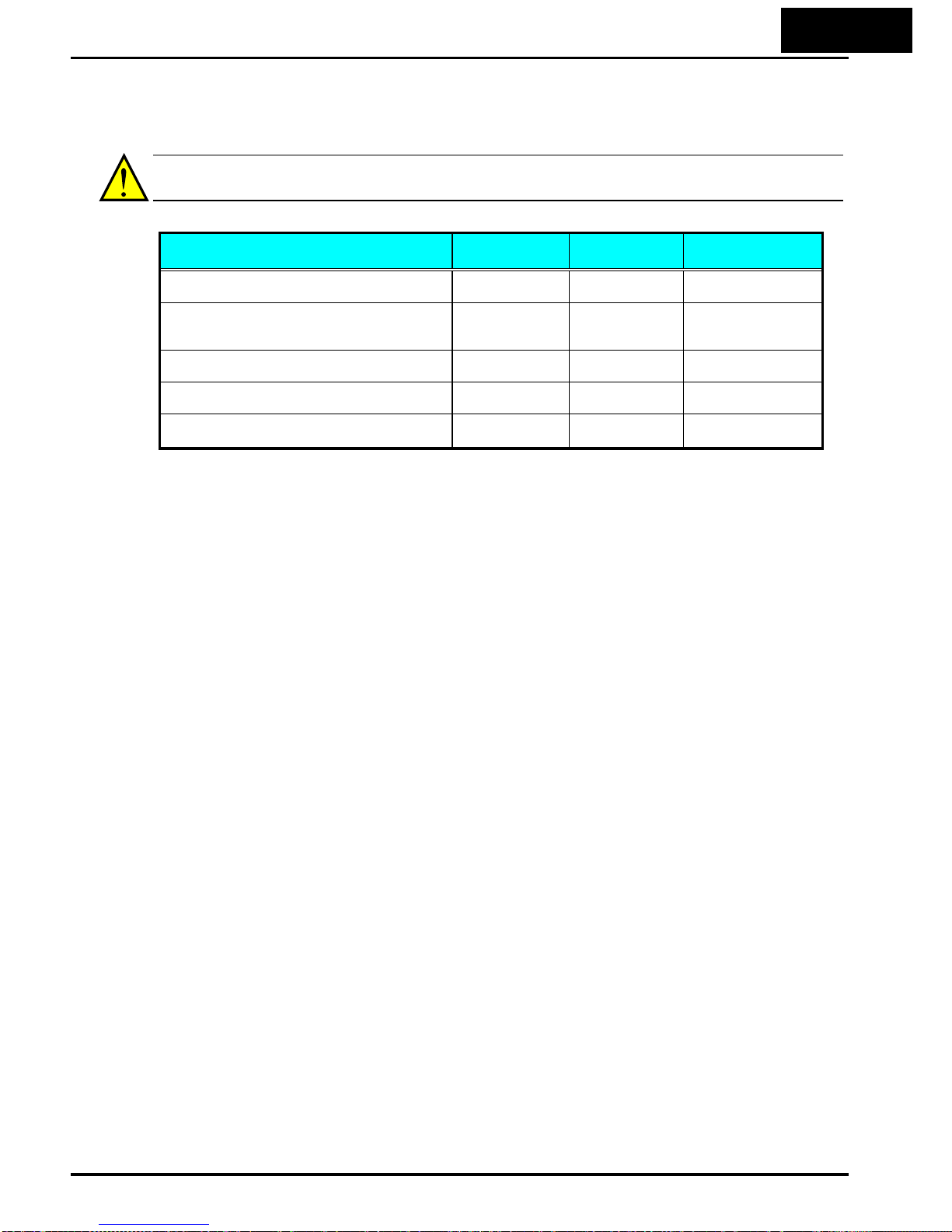
2−17
Terminal Dimensions and Torque Specs
The terminal screw dimensions for all WJ200 inverters are listed in table below. This
information is useful in sizing spade lug or ring lug connectors for wire terminations.
WARNING: Tighten the screws with the specified torque in the table below. Check for
any loosening of screws. Otherwise, there is the danger of fire.
Types
Screw
Diameter
Width
(mm)
Tightening Torque
(N•m)
WJ200 - 001S,002S,004S
WJ200 - 001L,002L,004L,007L
M3.5 7.6 1.0
WJ200 - 007S,015S,022S
WJ200 - 015L,022L,037L
WJ200 - 004H,007H,015H,022H,030H,040H
M4 10 1.4
WJ200 - 055L,075L
WJ200 – 055H,075H
M5 13 3.0
WJ200 - 110L
WJ200 - 110H,150H
M6 17.5 3.9 to 5.1
WJ200 - 150L M8 23 5.9 to 8.8
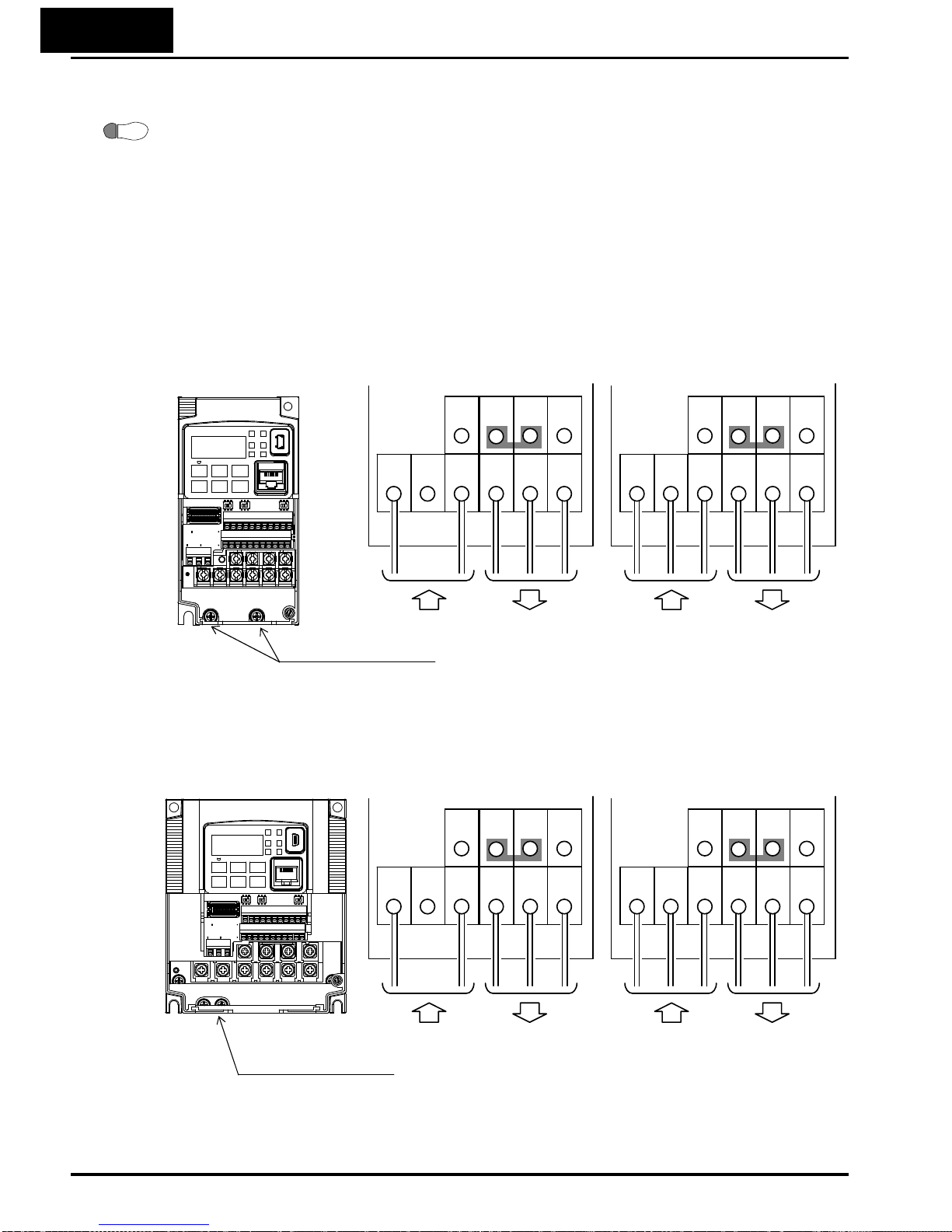
2−18
Wire the Inverter Input to a Supply
Step 6: In this step, you will connect wiring to the input of the inverter. First, you must
determine whether the inverter model you have required three-phase power only, or
single-phase power only. All models have the same power connection terminals [R/L1],
[S/L2], and [T/L3]. So you must refer to the specifications label (on the side of the
inverter) for the acceptable power source types! For inverters that can accept
single-phase power and are connected that way, terminal [S/L2] will remain
unconnected.
6
Note the use of ring lug connectors for a secure connection.
Single-phase 200V 0.1 to 0.4kW
Three-phase 200V 0.1 to 0.75kW
Single-phase Three-phase
Single-phase 200V 0.75 to 2.2kW
Three-phase 200V 1.5, 2.2kW
Three-phase 400V 0.4 to 3.0kW
Chassis Ground (M4)
L1
Power input Output to Motor
N U/T1 V/T2 W/T3
RB
+1
+
-
R/L1
Power input Output to Motor
S/L2 T/L3 U/T1 V/T2 W/T3
RB
PD/+1
P/+ N/-
Single-phase Three-phase
Chassis Ground (M4)
L1
Power input Output to Motor
N U/T1 V/T2 W/T3
RB
+1
+
-
R/L1
Power input Output to Motor
S/L2 T/L3 U/T1 V/T2 W/T3
RB
PD/+1
P/+ N/-

2−19
Three-phase 200V 3.7kW
Three-phase 400V 4.0kW
Three-phase 200V 5.5, 7.5kW
Three-phase 400V 5.5, 7.5kW
W/T3 V/T2 U/T1 N L1
-
+
+1
RB
Chassis Ground (M4)
Power input Output to Motor
G G RB
N/-
P/+
PD/+1
W/T3 V/T2 U/T1
R/L1 S/L2 T/L3
Power input Output to Motor

2−20
Three-phase 200V 11kW
Three-phase 400V 11, 15kW
Three-phase 200V 15kW
NOTE: An inverter powered by a portable power generator may receive a distorted
power waveform, overheating the generator. In general, the generator capacity should
be five times that of the inverter (kVA).
G G RB
N/-
P/+
PD/+1
W/T3 V/T2 U/T1
R/L1 S/L2 T/L3
Power input Output to Motor
G G RB
N/-
P/+
PD/+1
W/T3 V/T2 U/T1
R/L1 S/L2 T/L3
Power input Output to Motor

2−21
CAUTION: Be sure that the input voltage matches the inverter specifications:
• Single-phase 200 to 240 V 50/60 Hz (0.1kW~2.2kW) for SF models
• Three-phase 200 to 240 V 50/60 Hz (0.1kW~15kW) for LF models
• Three-phase 380 to 480 V 50/60Hz (0.4kW~15kW) for HF models
CAUTION: Be sure not to power a three-phase-only inverter with single-phase power.
Otherwise, there is the possibility of damage to the inverter and the danger of fire.
CAUTION: Be sure not to connect an AC power supply to the output terminals.
Otherwise, there is the possibility of damage to the inverter and the danger of injury
and/or fire.
Power Input
Output to Motor
WJ200 Inverter
CAUTION: Remarks for using ground fault interrupter breakers in the main power
supply: Adjustable frequency inverter with integrated CE-filters and shielded
(screened) motor cables have a higher leakage current toward earth GND. Especially
at the moment of switching ON this can cause an inadvertent trip of ground fault
interrupters. Because of the rectifier on the input side of the inverter there is the
possibility to stall the switch-off function through small amounts of DC current.
Please observe the following:
• Use only short time-invariant and pulse current-sensitive ground fault interrupters
with higher trigger current.
• Other components should be secured with separate ground fault interrupters.
• Ground fault interrupters in the power input wiring of an inverter are not an
absolute protection against electric shock.
CAUTION: Be sure to install a fuse in each phase of the main power supply to the
inverter. Otherwise, there is the danger of fire.
CAUTION: For motor leads, ground fault interrupter breakers and electromagnetic
contactors, be sure to size these components properly (each must have the capacity for
rated current and voltage). Otherwise, there is the danger of fire.

2−22
Wire the Inverter Output to Motor
Step 7: The process of motor selection is beyond the scope of this manual. However, it
must be an AC induction motor with three phases. It should also come with a chassis
ground lug. If the motor does not have three power input leads, stop the installation
and verify the motor type. Other guidelines for wiring the motor include:
7
• Use an inverter-grade motor for maximum motor life (1600V insulation).
• For standard motors, use the AC reactor accessory if the wiring between the
inverter and motor exceeds 10 meters in length.
Simply connect the motor to the terminals [U/T1], [V/T2], and [W/T3] as shown in
page 2-17 to 2-19. This is a good time to connect the chassis ground lug on the drive as
well. The motor chassis ground must also connect to the same point. Use a star ground
(single-point) arrangement, and never daisy-chain the grounds (point-to-point).
• Check the mechanical integrity of each wire crimp and terminal connection.
• Replace the housing partition that covers access to the power connections.
CAUTION: Power terminal assignment is different compared to old models such as L100, L200
series, etc,. Pay attention when wiring the power cable
Logic Control Wiring
After completing the initial installation and powerup test in this chapter, you may need
to wire the logic signal connector for your application. For new inverter
users/applications, we highly recommend that you first complete the powerup test in
this chapter without adding any logic control wiring. Then you will be ready to set the
required parameters for logic control as covered in Chapter 4, Operations and
Monitoring.

2−23
Uncover the Inverter Vents
Step 8: After mounting and wiring the inverter,
remove any covers from the inverter housing. This
includes material over the side ventilation ports.
8
Ventilation holes (top)
Ventilation holes
(both sides)
WARNING: Make sure the input power to the
inverter is OFF. If the drive has been powered,
leave it OFF for five minutes before continuing.
Powerup Test
9 Step 9: After wiring the inverter and motor, you’re ready to do a powerup test. The
procedure that follows is designed for the first-time use of the drive. Please verify the
following conditions before conducting the powerup test:
• You have followed all the steps in this chapter up to this step.
• The inverter is new, and is securely mounted to a non-flammable vertical surface.
• The inverter is connected to a power source and a motor.
• No additional wiring of the inverter connectors or terminals has been done.
• The power supply is reliable, and the motor is a known working unit, and the motor
nameplate ratings match the inverter ratings.
• The motor is securely mounted, and is not connected to any load.
Goals for the Powerup Test
If there are any exceptions to the above conditions at this step, please take a moment
to take any measures necessary to reach this basic starting point. The specific goals of
this powerup test are:
1. Verify that the wiring to the power supply and motor is correct.
2. Demonstrate that the inverter and motor are generally compatible.
3. Get an introduction to the use of the built-in operator keypad.
The powerup test gives you an important starting to ensure a safe and successful
application of the Hitachi inverter. We highly recommend performing this test before
proceeding to the other chapters in this manual.

2−24
Pre-test and Operational Precautions
The following instructions apply to the powerup test, or to any time the inverter is
powered and operating. Please study the following instructions and messages before
proceeding with the powerup test.
1. The power supply must have fusing suitable for the load. Check the fuse size chart
presented in Step 5, if necessary.
2. Be sure you have access to a disconnect switch for the drive input power if
necessary. However, do not turn OFF power during inverter operation unless it is
an emergency.
3. Turn the keypad potentiometer to the minimum position (full counter-clockwise).
CAUTION: The heat sink fins will have a high temperature. Be careful not to touch
them. Otherwise, there is the danger of getting burned.
CAUTION: The operation of the inverter can be easily changed from low speed to high
speed. Be sure to check the capability and limitations of the motor and machine before
operating the inverter. Otherwise, there is the danger of injury.
CAUTION: If you operate a motor at a frequency higher than the inverter standard
default setting (50Hz/60Hz), be sure to check the motor and machine specifications
with the respective manufacturer. Only operate the motor at elevated frequencies after
getting their approval. Otherwise, there is the danger of equipment damage and/or
injury.
CAUTION: Check the following before and during the Powerup test. Otherwise, there
is the danger of equipment damage.
• Is the shorting bar between the [+1] and [+] terminals installed? DO NOT power
or operate the inverter if the jumper is removed.
• Is the direction of the motor rotation correct?
• Did the inverter trip during acceleration or deceleration?
• Were the rpm and frequency meter readings as expected?
• Were there any abnormal motor vibration or noise?
Powering the Inverter
If you have followed all the steps, cautions and warnings up to this point, you’re ready
to apply power. After doing so, the following events should occur:
• The
POWER
LED will illuminate.
• The numeric (7-segment) LEDs will display a test pattern, then stop at
0.0
.
• The
Hz
LED will be ON.
If the motor starts running unexpectedly or any other problem occurs, press the STOP
key. Only if necessary should you remove power to the inverter as a remedy.
NOTE: If the inverter has been previously powered and programmed, the LEDs (other
than the POWER LED) may illuminate differently than as indicated above. If
necessary, you can initialize all parameters to the factory default settings. See
“Restoring Factory Default Settings
” on page 6-14.

2−25
Using the Front Panel Keypad
Please take a moment to familiarize yourself with the keypad layout shown in the
figure below. The display is used in programming the inverter’s parameters, as well as
monitoring specific parameter values during operation.
Key and Indicator Legend
Items Contents
(1) POWER LED Turns ON (Green) while the inverter is powered up.
(2) ALARM LED Turns ON (Red) when the inverter trips.
(3) Program LED
¾ Turns ON (Green) when the display shows changeable parameter.
¾ Blinks when there is a mismatch in setting.
(4) RUN LED Turns ON (Green) when the inverter is driving the motor.
(5) Monitor LED [Hz] Turns ON (Green) when the displayed data is frequency related.
(6) Monitor LED [A] Turns ON (Green) when the displayed data is current related.
(7) Run command LED Turns ON (Green) when a Run command is set to the operator. (Run key is effective.)
(8) 7-seg LED Shows each parameter, monitors etc.
(9) Run key Makes inverter run.
(10) Stop/reset key
¾ Makes inverter decelerates to a stop.
¾ Reset the inverter when it is in trip situation
(11) ESC key
¾ Go to the top of next function group, when a function mode is shown
¾ Cancel the setting and return to the function code, when a data is shown
¾ Moves the cursor to a digit left, when it is in digit-to-digit setting mode
¾ Pressing for 1 second leads to display data of d001, regardless of current display.
(12) Up key
(13) Down key
¾ Increase or decrease the data.
¾ Pressing the both keys at the same time gives you the digit-to-digit edit.
(14) SET key
¾ Go to the data display mode when a function code is shown
¾ Stores the data and go back to show the function code, when data is shown.
¾ Moves the cursor to a digit right, when it is in digit-to-digit display mode
(15) USB connector Connect USB connector (mini-B) for using PC communication
(16) RJ45 connector Connect RJ45 jack for remote operator. (RS422 only)
1
2
RUN
ESC
STOP/
RESET
SET
8888
RUN
Hz
A
PWR
ALM
PRG
(1) POWER LED
(2) ALARM LED
(8) 7-seg LED
(4) RUN LED
(10) Stop/reset key
(15) USB connector
(3) Program LED
(16) RJ45 connector
(RS422 only)
(14) Set key
(13) Down key(12) Up key
(11) Escape key
(9) RUN key
(7) Run command LED
(5) Monitor LED [Hz]
(6) Monitor LED [A]

2−26
Keys, Modes, and Parameters
The purpose of the keypad is to provide a way to
change modes and parameters. The term function
applies to both monitoring modes and parameters.
These are all accessible through function codes that
are primary 4-character codes. The various functions
are separated into related groups identifiable by the
left-most character, as the table shows.
1
2
RUN
ESC
STOP/
RESET
SET
Function
Group
Type (Category) of Function Mode to Access
PRG LED
Indicator
“D” Monitoring functions Monitor
“F” Main profile parameters
Program
z
“A” Standard functions
Program
z
“B” Fine tuning functions
Program
z
“C” Intellig ent terminal functions
Program
z
“H” Motor constant related functi ons
Program
z
“P” Pulse train input, torque, EzSQ, and
communication related functions
Program
z
“U” User selected parameters
Program
z
“E” Error codes
−
−
You can see from the following page how to monitor and/or program the parameters.
Keypad Navigation Map
The WJ200 Series inverter drives have many programmable functions and parameters.
Chapter 3 will cover these in detail, but you need to access just a few items to perform
the powerup test. The menu structure makes use of function codes and parameter
codes to allow programming and monitoring with only a 4-digit display and keys and
LEDs. So, it is important to become familiar with the basic navigation map of
parameters and functions in the diagram below. You may later use this map as a
reference.
8888
RUN PWR
Hz
A
ALM
PRG

2−27
d001
V U
ESC
SET
Group "d"
Func. code display
0.00
d002
d104
F001
V U
Group "F"
Func. code display
F002
F004
50.00
50.01
SET
SET ESC
SET ESC
Save
Data display (F001 to F003)
Data does not blink because of real time synchronizing
: Saves the data in EEPROM and returns to func. code display.
: Returns to func. code display without saving data.
SET
ESC
A001
V U
ESC
Func. code display
: Jumps to the next group
ESC
SET
ESC
: Moves to data display
Func. code display
Group "A"
Func. code display
A002
Group "b"
b001
ESC
Group "C"
C001
ESC
Group "H"
H001
ESC
Group "P"
P001
ESC
Group "U"
U001
ESC
A165
ESC
SET
SET
01
SET
Data display
When data is changed, the display starts blinking, which means that
new data has not been activated yet.
ESC
SET
: Cancels the data change and returns to func. code display.
: Saves the data in EEPROM and returns to func. code display.
ESC
00
Refer to 2-34 for further information.
Press the both up and down key at the same
time in func. code or data display, then
single-digit edit mode will be enabled.
V
U
NOTE: Pressing the [ESC] key will make the display go to the top of next function
group, regardless the display contents. (e.g. A021 Æ [ESC] Æ b001)
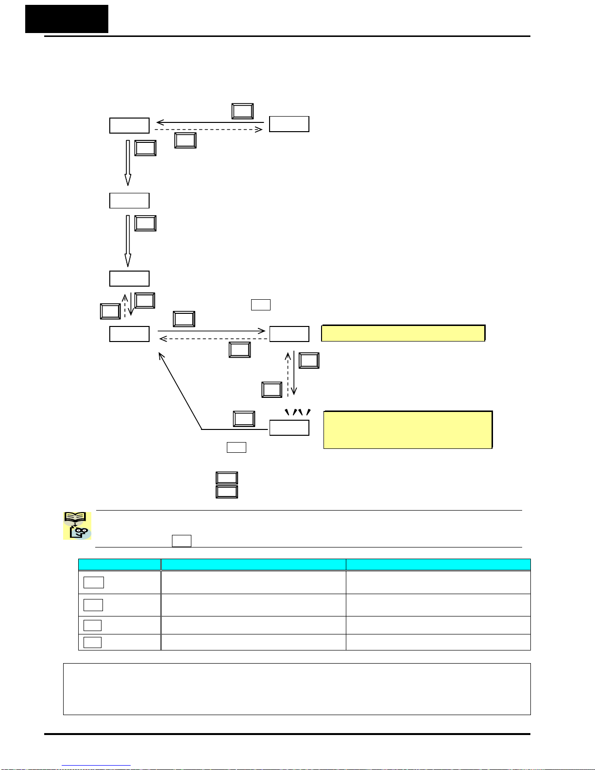
2−28
[Setting example]
After power ON, changing from 0.00 display to change the b083 (carrier frequency) data.
Function code dxxx are for monitor and not possible to change.
Function codes Fxxx other than F004 are reflected on the performance just after changing the data
(before pressing SET key), and there will be no blinking.
When a function code is shown… When a data is shown…
ESC key
Move on to the next function group
Cancels the change and moves back to
the function code
SET key Move on to the data display
Fix and stores the data and moves back
to the function code
U key Increase function code Increase data value
V key Decrease function code Decrease data value
Note
Keep pressing for more than 1 second leads to d001 display, regardless the display situation. But note that
the display will circulates while keep pressing the [ESC] key because of the original function of the key.
(e.g. F001 Æ A001 Æ b001 Æ C001 Æ …Æ displays 50.00 after 1 second)
b001
b083 5.0
Display is solid lighting.
12.0
F001
d001
0.00
c Data of will be shown on the
display after the first power ON
d Press [ESC] key to show
the function code
e Press [ESC] key to move on to the function group
f Press [ESC] key twice to move on to the function group
g Press Up key to change increase function code ( Æ
h Press SET key to display the data of
d001
F001
b001.
b001 b083)
b083
ESC
i Press up key to increase the
data ( Æ
i Press SET key to set
5.0 12.0)
SET
ESC
ESC
U
V
SET
ESC
U
and save the data
When data is changed, the display
starts blinking, which means that new
data has not been activated yet.
V
:Fix and stores the data and moves back to the function code
:Cancels the change and moves back to the function code
SET
SET
ESC
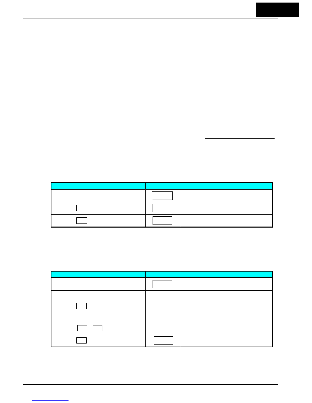
2−29
Selecting Functions and Editing Parameters
To prepare to run the motor in the powerup test, this section will show how to
configure the necessary parameters:
1. Select the digital operator as the source of motor speed command (A001=02).
2. Select the digital operator as the source of the RUN command (A002=02).
3. Set the motor base frequency (A003) and AVR voltage of the motor (A082).
4. Set the motor current for proper thermal protection (b012).
5. Set the number of poles for the motor (H004).
The following series of programming tables are designed for successive use. Each table
uses the previous table’s final state as the starting point. Therefore, start with the first
and continue programming until the last one. If you get lost or concerned that some of
the other parameters setting may be incorrect, refer to “Restoring Factory Default
Settings” on page 6-8.
Prepare to Edit Parameters – This sequence begins with powering ON the inverter,
then it shows how to navigate to the “A” Group parameters for subsequent settings.
You can also refer to the “Keypad Navigation Map
” on page 2-26 for orientation
throughout the steps.
Action Display Func./Parameter
Turn ON the inverter
0.0
Inverter output frequency displayed
(0Hz in stop mode)
Press the ESC key.
d001
“d” group selected
Press the ESC key 2 times.
A001
“A” group selected
1. Select the digital operator for Speed Command – The inverter output frequency
can be set from several sources, including an analog input, memory setting, or the
network, for example. The powerup test uses the keypad as the speed control source
for your convenience. Note that the default setting depends on the country.
Action Display Func./Parameter
(Starting point)
A001
“A” Group selected
Speed command source setting
Press the SET key
01
00…Potentiometer of ext. operator
01…Control terminals
02…Digital operator (F001)
03…ModBus network
etc.
Press the U / V key to select
02
02…Digital operator (selected)
Press the SET key to store
A001
Stores parameter, returns to “A001”
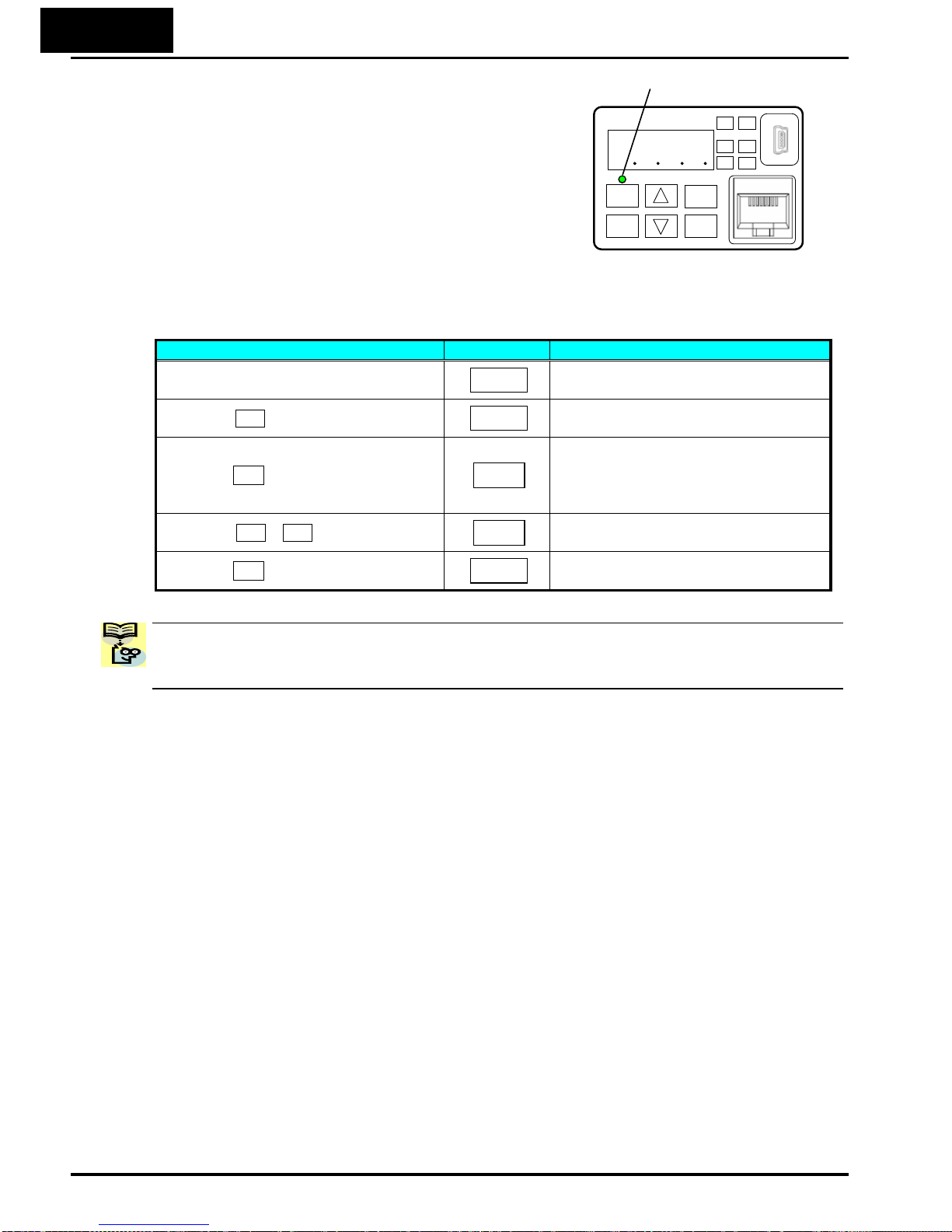
2−30
2. Select the digital operator for RUN Command –
To RUN command causes the inverter to accelerate
the motor to the selected speed. The Run command
can arrive from various sources, including the
control terminals, the Run key on the keypad or the
network. In the figure to the right, notice the Run
Key Enable LED, just above the Run key. If the LED
is ON, the Run key is already selected as the source,
and you may skip this step. Note that the default
setting depends on the country.
Run Key Enable LED
1
2
RUN
ESC
STOP/
RESET
SET
If the Potentiometer Enable LED is OFF, follow these steps below (the table resumes
action from the end of the previous table).
Action Display Func./Parameter
(Starting point)
A001
Speed command source setting
Press the U key
A002
Run command source setting
Press the SET key
01
01…Control terminal
02…Digital operator
03…ModBus network input
etc.
Press the U / V key to select
02
02… Digital operator (selected)
Press the SET key to store
A002
Stores parameter, returns to “A002”
NOTE: After completing the steps above, the Run Key Enable LED will be ON. This
does not mean the motor is trying to run; it means that the RUN key is now enabled.
DO NOT press the RUN key at this time – complete the parameter setup first.
8888
RUN PWR
Hz
A
ALM
PRG

2−31
3. Set the Motor Base Frequency and AVR voltage of the motor – The motor is
designed to operate at a specific AC frequency. Most commercial motors are designed
for 50/60 Hz operation. First, check the motor specifications. Then follow the steps
below to verify the setting or correct it for your motor. DO NOT set it greater than
50/60 Hz unless the motor manufacturer specifically approves operation at the higher
frequency.
Action Display Func./Parameter
(Starting point)
A002
Run command source setting
Press the U key once.
A003
Base frequency setting
Press the SET key.
60.0.
or
50.0
Default value for the base frequency.
US = 60 Hz, Europe = 50 Hz
Press the U / V key to select
60.0
Set to your motor specs (your display
may be different)
Press the SET key.
A003
Store parameter, returns to “A003”
CAUTION: If you operate a motor at a frequency higher than the inverter standard
default setting (50Hz/60Hz), be sure to check the motor and machine specifications
with the respective manufacturer. Only operate the motor at elevated frequencies after
getting their approval. Otherwise, there is the danger of equipment damage.
Set the AVR Voltage Setting – The inverter has an Automatic Voltage Regulation (AVR)
function. It adjusts the output voltage to match the motor’s nameplate voltage rating.
The AVR smoothes out fluctuation in the input power source, but note that it does not
boost the voltage in the event of a brown-out. Use the AVR setting (A082) that most
closely matches the one for your motor.
• 200V class: 200 / 215 / 220 / 230 / 240 VAC
• 400V class: 380 / 400 / 415 / 440 / 460 / 480 VAC
To set the motor voltage, follow the steps on the following table.
Action Display Func./Parameter
(Starting point)
A003
Base frequency setting
Press the U key and hold until Æ
A082
AVR voltage select
Press the SET key.
A230
or
A400
Default value for AVR voltage:
200V class = 230VAC
400V class = 400VAC (HFE)
= 460VAC (HFU)
Press the U / V key to select
A215
Set to your motor specs (your display
may be different)
Press the SET key.
A082
Store parameter, returns to “A082”
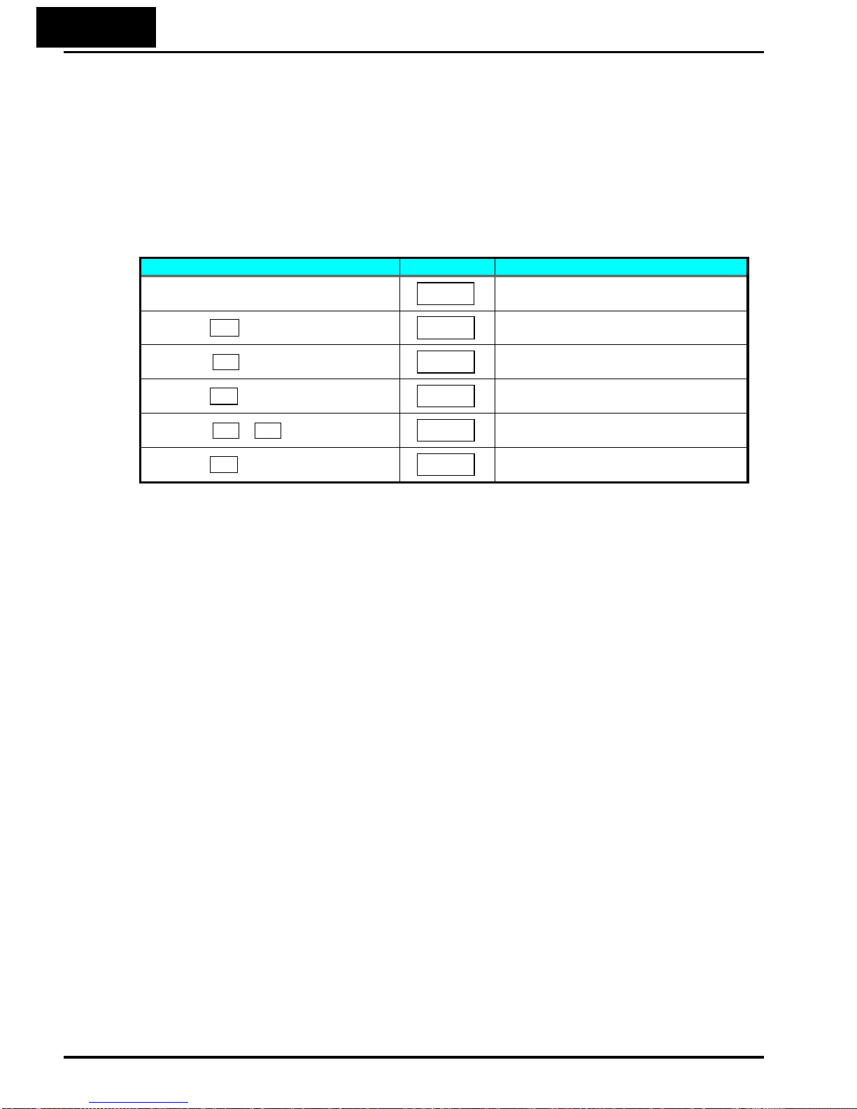
2−32
4. Set the Motor Current – The inverter has thermal overload protection that is
designed to protect the inverter and motor from overheating due to an excessive load.
The inverter’s uses the motor’s current rating to calculate the time-based heating effect.
This protection depends on using correct current rating for your motor. The level of
electronic thermal setting, parameter B012, is adjustable from 20% to 100% of the
inverter’s rated current. A proper configuration will also help prevent unnecessary
inverter trip events.
Read the motor’s current rating on its manufacturer’s nameplate. Then follow the steps
below to configure the inverter’s overload protection setting.
Action Display Func./Parameter
(Starting point)
A082
AVR voltage select
Press the ESC key.
b001
First “B” Group parameter selected
Press the U key and hold until Æ
b012
Level of electronic thermal setting
Press the SET key.
b160
Default value will be 100% of inverter
rated current
Press the U / V key to select
b140
Set to your motor specs (your display
may be different)
Press the SET key.
b012
Store parameter, returns to “b012”
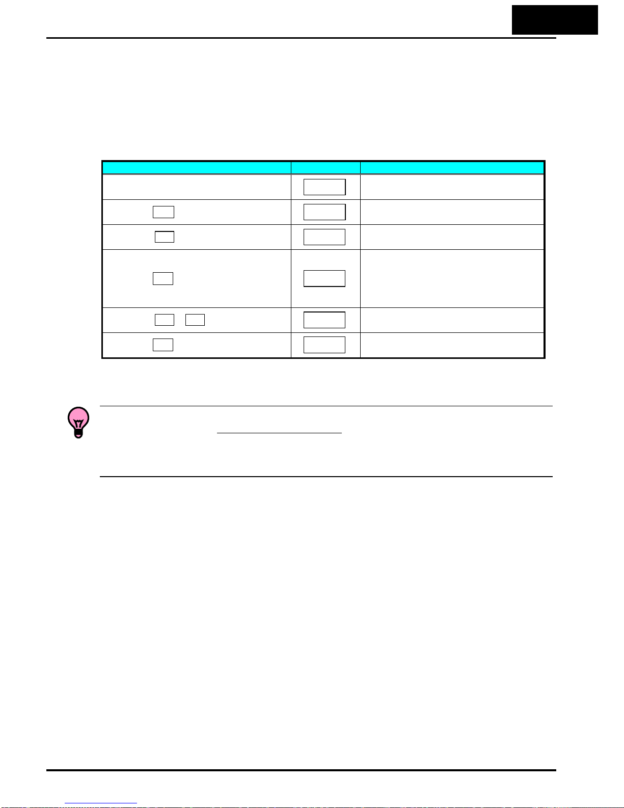
2−33
5. Set the Number of Motor Poles – The motor’s internal winding arrangement
determines its number of magnetic poles. The specification label on the motor usually
indicates the number of poles. For proper operation, verify the parameter setting
matches the motor poles. Many industrial motors have four poles, corresponding to the
default setting in the inverter (H004).
Follow the steps in the table below to verify the motor poles setting and change if
necessary (the table resumes action from the end of the previous table.)
Action Display Func./Parameter
(Starting point)
b012
Level of electronic thermal setting
Press the ESC key two times
H001
“H” Group selected
Press the U key three times
H004
Motor poles parameter
Press the SET key.
H004
2 = 2 poles
4 = 4 poles (default)
6 = 6 poles
8 = 8 poles
10 = 10 poles
Press the U / V key to select
H004
Set to your motor specs (your display
may be different)
Press the SET key.
H004
Store parameter, returns to “H004”
This step concludes the parameter setups for the inverter. You are almost ready to run
the motor for the first time!
TIP: If you became lost during any of these steps, first observe the state of the PRG
LED. Then study the “Keypad Navigation Map on page 2-26 to determine the current
state of the keypad controls and display. As long as you do not press the SET key, no
parameter will be changed by keypad entry errors. Note that power cycling the inverter
causes it to power up Monitor Mode, displaying the value for D001 (output frequency).
The next section will show you how to monitor a particular parameter from the display.
Then you will be ready to run the motor.
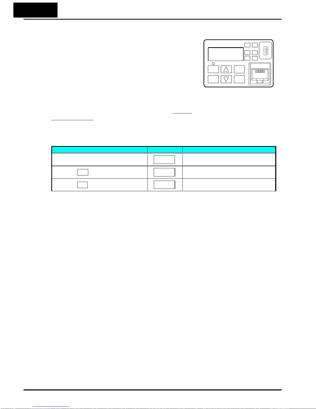
2−34
Monitoring Parameters with the Display
After using the keypad for parameter editing, it’s a
good idea to switch the inverter from Program Mode
to Monitor Mode. The PRG LED will be OFF, and the
Hertz or Ampere LED indicates the display units.
For the powerup test, monitor the motor speed
indirectly by viewing the inverter’s output frequency.
The output frequency must not be confused with base
frequency (50/60 Hz) of the motor, or the carrier
frequency (switching frequency of the inverter, in the
kHz range). The monitoring functions are in the “D”
list, located near the top left of the “Keypad
Navigation Map”on page 2-26.
Output frequency (speed) set – Resuming keypad operation from the previous table,
follow the steps below.
Action Display Func./Parameter
(Starting point)
H004
Motor poles parameter
Press the ESC key four times
F001
F001 is selected
Press the SET key.
b100
Set frequency displayed
Running the Motor
If you have programmed all the parameters up to this point, you’re ready to run the
motor! First, review this checklist:
1. Verify the power LED is ON. If not, check the power connections.
2. Verify the Run Key Enable LED is ON. If it is OFF, check the A002 setting.
3. Verify the PRG LED is OFF. If it is ON, review the instructions above.
4. Make sure the motor is disconnected from any mechanical load.
5. Now, press the RUN key on the keypad. The RUN LED will turn ON.
6. Press the [U] key for a few seconds. The motor should start turning.
7. Press the STOP key to stop the motor rotation.
1
2
RUN
ESC
STOP/
RESET
SET
8888
RUN PWR
Hz ALM
A
PRG
d.0.0.1.

2 35−
Single-Digit Edit Mode
If a target function code or data is far from current data, using the single-digit edit
mode makes it quicker. Pressing the up key and down key at the same time leads you
to go into the digit-to-digit changing mode.
(Note) When pressing [ESC] with cursor on the highest digit, the cursor will jump to the lowest digit.
((A) and (B) in above figure.)
(Note) When pressing up key and down key at the same time in single-digit edit mode, the
single-digit edit mode is disabled and goes back to normal mode.
F001
F001
1st digit will be
blinking. Use up/down
keys to change the
value of the digit.
F0 01
A001 F 101
F001
F011
F001
F002
50.00
50.00 50.00 50.0 0
50.00
60.00 51.00 50.1 0
50.01
If not existing codes are selected, the data sill not move to the function
code but blinking digit will move again to the left end digit.
(A)
△ ▽
(A)
(B)
(B)
: Move cursor to left.
: Move cursor to right or set the func.code/data (lowest digit only)
While in Single-digit edit mode (single digit is blinking):
SET
ESC
2nd digit will be
blinking. Use up/down
keys to change the
value of the digit.
3rd digit will be
blinking. Use up/down
keys to change the
value of the digit.
4th digit will be blinking.
Use up/down keys to
change the value of the
digit.
1st digit will be blinking.
Use up/down keys to
change the value of the
digit.
2nd digit will be blinking.
Use up/down keys to
change the value of the
digit.
3rd digit will be blinking.
Use up/down keys to
change the value of the
digit.
4th digit will be blinking.
Use up/down keys to
change the value of the
digit.
ESC
SET
ESC
V U
SET
ESC
V U V U
SET
ESC
SET
ESC
V U
SET
ESC
U
V
SET
SET
SET
ESC
ESC
V
U V
U V
U
U
V

2−36
Powerup Test Observations and Summary
Step 10: Reading this section will help you make some useful observations when first
running the motor.
Error Codes – If the inverter displays an error code (format is “E xx”), see “Monitoring
Trip Events, History, & Conditions” on page 6-5 to interpret and clear the error.
Acceleration and Deceleration – The WJ200 inverter has programmable acceleration
and deceleration value. The test procedure left these at the default value, 10 seconds.
You can observe this by setting the frequency F001 at about half speed before running
the motor. Then press RUN, and the motor will take 5 seconds to reach a steady speed.
Press the STOP key to see a 5 second deceleration to a STOP.
State of Inverter at Stop – If you adjust the motor’s speed to zero, the motor will slow
to a near stop, and the inverter turns the outputs OFF. The high-performance WJ200
can rotate at a very slow speed with high torque output, but not zero (must use servo
systems with position feedback for that feature). This characteristic means you must
use a mechanical brake for some applications.
Interpreting the Display – First, refer to the output frequency display readout. The
maximum frequency setting (parameter A044) defaults to 50 Hz or 60 Hz (Europe and
United States, respectively) for your application.
Example: Suppose a 4-pole motor is rated for 60 Hz operation, so the inverter is
configured to output 60 Hz at full scale. Use the following formula to calculate the
rpm.
Speed in RPM
RPM
polesof
Frequency
polesofPairs
Frequency
1800
4
12060
#
12060
=
×=×=×
=
The theoretical speed for the motor is 1800 RPM (speed of torque vector rotation).
However, the motor cannot generate torque unless its shaft turns at a slightly different
speed. This difference is called slip. So it’s common to see a rated speed of
approximately 1750 RPM on a 60 Hz, 4-pole motor. Using a tachometer to measure
shaft speed, you can see the difference between the inverter output frequency and the
actual motor speed. The slip increases slightly as the motor’s load increases. This is
why the inverter output value is called “frequency”, since it is not exactly equal to
motor speed.
Run/Stop Versus Monitor/Program Modes – The
Run LED on the inverter is ON in Run Mode,
and OFF in Stop Mode. The Program LED is ON
when the inverter is in Program Mode, and OFF
for Monitor Mode. All four mode combinations
are possible. The diagram to the right depicts
the modes and the mode transitions via keypad.
NOTE: Some factory automation devices such as PLCs have alternative Run/Program
10
modes; the device is in either one mode or the other. In the Hitachi inverter, however,
Run Mode alternates with Stop Mode, and Program Mode alternates with Monitor
Mode. This arrangement lets you program some value while the inverter is operating –
providing flexibility for maintenance personnel.
Run
STOP/
RESET
Stop
Monitor
RUN
ESC SET
Program

3−1
Configuring
Drive Parameters
In This Chapter… page
- Choosing a Programming Device ................................................... 2
- Using the Keypad Devices .............................................................. 3
- “D” Group: Monitoring Functions .................................................. 7
- “F” Group: Main Profile Parameters ............................................. 11
- “A” Group: Standard Functions ................................................... 12
- “B” Group: Fine Tuning Functions ............................................... 44
- “C” Group: Intelligent Terminal Functions .................................. 83
- “H” Group: Motor Constants Functions .................................... 104
: Sensorless Vector Control ...................................... 107
: Auto-tuning Function .............................................. 108
- “P” Group: Other Parameters ...................................................... 111
: Simple Positioning ................................................... 114
3

3−2
Choosing a Programming Device
Introduction
Hitachi variable frequency drives (inverters) use the latest electronics technology for
getting the right AC waveform to the motor at the right time. The benefits are many,
including energy savings and higher machine output or productivity. The flexibility
required to handle a broad range of applications has required ever more configurable
options and parameters – inverter are now a complex industrial automation component.
And this can make a product seem difficult to use, but the goal of this chapter is to make
this easier for you.
As the powerup test in Chapter 2 demonstrated, you do not have to program very many
parameters to run the motor. In fact, most applications would benefit only from
programming just a few, specific parameters. This chapter will explain the purpose of
each set of parameters, and help you choose the ones that are important to your
application.
If you are developing a new application for the inverter and a motor, finding the right
parameters to change is mostly an exercise in optimization. Therefore, it is okay to
begin running the motor with a loosely tuned system. By making specific, individual
changes and observing their effects, you can achieve a finely tuned system.
Introduction of Inverter Programming
The front panel keypad is the first and best way to get to know the inverter’s
capabilities. Every function or programmable parameter is accessible from the keypad.

3−3
Using the Keypad Devices
The WJ200 Series inverter front keypad contains all the elements for both monitoring
and programming parameters. The keypad layout is pictured below. All other
programming devices for the inverter have a similar key arrangement and function.
Key and Indicator Legend
• Run LED – ON when the inverter output is ON and the motor is developing torque
(Run Mode), and OFF when the inverter output is OFF (Stop Mode).
• Program LED – This LED is ON when the inverter is ready for parameter editing
(Program Mode). It is OFF when the parameter display is monitoring data (Monitor
Mode).
• Run Key Enable LED – This LED is ON when the inverter is ready to respond to the
Run key, OFF when the Run key is disabled.
• Run Key – Press this key to run the motor (the Run Enable LED must be ON first).
Parameter F004, Keypad Run Key Routing, determines whether the Run key
generates a Run FWD or Run REV command.
• Stop/Reset Key – Press this key to stop the motor when it is running (uses the
programmed deceleration rate). This key will also reset an alarm that has tripped.
• Parameter Display – A 4-digit, 7-segment display for parameters and function codes.
• Display Units, Hertz/Amperes – One of these LEDs will be ON to indicate the units
associated with the parameter display.
• Power LED – This is ON when the power input to the inverter is ON.
• Alarm LED – ON when an inverter trip is active (alarm relay contact will be closed).
• Escape Key – This key is used to escape from the current situation.
• Up/Down keys – Use these keys alternatively to move up or down the lists of
parameter and functions shown in the display, and increment/decrement values.
• Set key – This key is used to navigate through the lists of parameters and functions
for setting and monitoring parameter values. When the unit is in Program Mode and
you have edited a parameter value, press the Set key to write the new value to the
EEPROM.
Display Units (Hertz / Amperes) LEDs
Parameter Display
Run key Enable LED
Run key
Escape key
Power LED
A
larm LED
Program LED
Remote operator
Connector (RJ45 )
(RS422 only)
USB port
(Mini B connector)
1
2
RUN
ESC
STOP/
RESET
SET
8888
RUN
Hz
A
PWR
ALM
PRG
Stop/Reset key
Up/Down keys
Set key
Run LED

3−4
Operational Modes
The RUN and PRG LEDs tell just part of the story;
Run Mode and Program Modes are independent
modes, not opposite modes. In the state diagram to
the right, Run alternates with Stop, and Program
Mode alternates with Monitor Mode. This is a very
important ability, for it shows that a technician can
approach a running machine and change some
parameters without shutting down the machine.
The occurrence of a fault during operation will cause
the inverter to enter Trip Mode as shown. An event
such as an output overload will cause the inverter to
exit the Run Mode and turn OFF its output to the
motor. In the Trip Mode, any request to run the
motor is ignored. You must clear the error by
pressing the Stop/Reset switch. See “Monitoring Trip
Events, History, & Conditions” on page 6-8.
Run Mode Edit
The inverter can be in Run Mode (inverter output is controlling motor) and still allow
you to edit certain parameters. This is useful in applications that must run continuously,
you need some inverter parameter adjustment.
The parameter tables in this chapter have a column titled “Run
Mode Edit”. An Ex mark
U means the parameter cannot be
edited; a Check mark
means the parameter can be edited.
The Software Lock Setting (parameter B031) determines when
the Run Mode access permission is in effect and access
permission in other conditions, as well. It is the responsibility
of the user to choose a useful and safe software lock setting for
the inverter operating conditions and personnel. Please refer to
“Software Lock Mode” on page 3-53 for more information.
Control Algorithms
The motor control program in the WJ200
inverter has two sinusoidal PWM switching
algorithms. The intent is that you select the
best algorithm for the motor and load
characteristics of your application. Both
algorithms generate the frequency output in a
unique way. Once configured, the algorithm is
the basis for other parameter settings as well
(see “Torque Control Algorithms
” on page 3-22).
Therefore, choose the best algorithm early in
your application design process.
Run Stop
RUN
STOP
RESET
Monitor Program
FUNC
Run Stop
RUN
STOP
RESET
Trip
STOP
RESET
Fault
Fault
Run
Mode
Edit
U
V/F control
constant torque (V/F-VC)
Output
Inverter Control Algorithms
V/F control,
variable (1.7) torque
V/F control,
Free V/f
Sensorless vector
Control (SLV)

3−5
Dual Rating Selection
The WJ200 series inverter has Dual Rating, so that it can work in two different types of
load condition, Constant torque application and Variable torque application. Select
parameter b049 depending on your application.
“b” Function
Run
Mode
Edit
Defaults
Func.
Code
Name Description Lnitial data Units
b049
Dual Rating Selection
00… (CT mode) / 01… (VT mode)
U
00
−
When changed, the rated output current and related items are changed automatically.
Differences between HD and ND are described below.
HD ND
Usage For heavy load with high torque required at start,
acceleration or deceleration
For normal load without
high torque required.
Applications Elevators, cranes, conveyers, etc. fans, pumps,
air-conditionings
Rated current
(example)
1.0A (3-phase 200V 0.1kW) 1.2A (3-phase 200V
0.1kW)
Overload current 150% 60 sec. 120% 60 sec.
Initial values of HD and ND are different shown as below table. Be sure to note that
when the dual rating selection b049 is changed except H003/H203, those initial values
are also changed. (Even if currently set value is within the range of both HD and ND,
data is initialized when b049 is changed.)
Name
Func.
code
HD ND
Range initial data Range initial data
V/f characteristic
curve
A044
A244
00: Const. torque
01: Reduced torque
02: Free V/F
03: SLV
00: Const. tq. 00: Const. torque
01: Reduced tq.
02: Free V/F
00: Const. tq.
DC braking force
for deceleration
A054 0 to 100 (%) 0 (%) 0 to 70 % 0 (%)
DC braking force
at start
A057 0 to 100 (%) 0 (%) 0 to 70 % 0 (%)
Carrier
frequency during
DC braking
A059
2.0 to 15.0(kHz) 5.0(kHz) 2.0 to 10.0(kHz) 2.0(kHz)
Overload
restriction level
b022
b222
(0.20 to 2.00)
× Rated current (A)
1.50× Rated
current (A)
(0.20 to 1.50)
× Rated current (A)
1.20× Rated
current (A)
Overload
restriction level
2
b025
Carrier
frequency
b083 2.0 to 15.0(kHz) 5.0(kHz) 2.0 to 10.0(kHz) 2.0(kHz)
Motor capacity
H003
H203
0.1 to 15(kW)
Depends on
type
0.2 to 18.5(kW)
One size up
to HD

3−6
When HD is selected, following parameters are not displayed.
Func.
code
Name
Func.
code
Name
d009 Torque command monitor C058 Over/under-torque level (FW,RG)
d010 Torque bias monitor C059 Output mode of Over/under-torque
d012 Torque monitor H001 Auto-tuning selection
b040 Torque limit selection H002/H202 Motor constant selection
b041 Torque limit (1) H005/H205 Motor speed response constant
b042 Torque limit (2) H020/H220 Motor constant R1
b043 Torque limit (3) H021/H221 Motor constant R2
b044 Torque limit (4) H022/H222 Motor constant L
b045 Torque LAD STOP selection H023/H223 Motor constant Io
b046 Reverse run protection H024/H224 Motor constant J
C054 Over-torque/under-torque selection P037 Torque bias value
C055 Over/under-torque level (FW,PW) P038 Torque bias polar selection
C056 Over/under-torque level (RV,RG) P039 Speed limit of Torque control (FW)
C057 Over/under-torque level (RV,PW) P040 Speed limit of Torque control (RV)
When ND is selected, following functions are not displayed in intelligent terminals.
Intelligent input terminals Intelligent output terminals
40:TL Torque Limit Selection 07:OTQ Over/under Torque Signal
41:TRQ1 Torque limit switch 1 10:TRQ Torque Limited Signal
42:TRQ1 Torque limit switch 2 - 52:ATR Enable torque command input - -

3−7
“D” Group: Monitoring Functions
You can access important parameter values with the “D” Group monitoring functions,
whether the inverter is in Run Mode or Stop Mode. After selecting the function code
number for the parameter you want to monitor, press the Function key once to show the
value on the display. In functions D005 and D006, the intelligent terminals use
individual segments of the display to show ON/OFF status.
If the inverter display is set to monitor a parameter and powerdown occurs, the inverter
stores the present monitor function setting. For your convenience, the display
automatically returns to the previously monitored parameter upon the next powerup.
“d” Function
Run
Mode
Edit
Units
Func.
Code
Name Description
D001
Output frequency monitor Real time display of output
frequency to motor from
0.0 to 400.0Hz
If b163 is set high, output frequency
(F001) can be changed by up/down
key with d001 monitoring.
−
Hz
D002
Output current monitor Filtered display of output current to
motor, range is
0 to 655.3 ampere (~99.9 ampere for
1.5kW and less)
−
A
D003
Rotation direction monitor Three different indications:
“F” …Forward
“o” …Stop
“r” …Reverse
− −
D004
Process variable (PV),
PID feedback monitor
Displays the scaled PID process
variable (feedback) value (A075 is
scale factor),
0.00 to 10000
−
% times
constant
D005
Intelligent input
terminal status
Displays the state of the intelligent
input terminals:
− −
D006
Intelligent output
terminal status
Displays the state of the intelligent
output terminals:
− −
ON
OFF
Relay
12 11
ON
OFF
7 6 5 4
3
2 1
Terminal numbers

3−8
“d” Function
Run
Mode
Edit
Units
Func.
Code
Name Description
D007
Scaled output frequency
monitor
Displays the output frequency
scaled by the constant in B086.
Decimal point indicates range:
0 to 3999
−
Hz times
constant
d008
Actual frequency monitor Displays the actual frequency,
range is -400 to 400 Hz
−
Hz
d009
Torque command monitor Displays the torque command,
range is -200 to 200 %
−
%
d010
Torque bias monitor Displays the torque bias value,
range is -200 to 200 %
−
%
d012
Output torque monitor Displays the output torque, range is
-200 to 200 %
−
%
D013
Output voltage monitor Voltage of output to motor,
Range is 0.0 to 600.0V
−
V
d014
Input power monitor Displays the input power, range is 0
to 999.9 kW
−
KW
d015
Watt-hour monitor Displays watt-hour of the inverter,
range is 0 to 9999000
−
D016
Elapsed RUN time monitor Displays total time the inverter has
been in RUN mode in hours.
Range is 0 to 9999 / 1000 to 9999 /
⎡100 to ⎡999 (10,000 to 99,900)
−
hours
D017
Elapsed power-on time
monitor
Displays total time the inverter has
been powered up in hours.
Range is 0 to 9999 / 1000 to 9999 /
⎡100 to ⎡999 (10,000 to 99,900)
−
hours
D018
Heat sink temperature
monitor
Temperature of the cooling fin,
range is -20~150
− °C
d022
Life check monitor Displays the state of lifetime of
electrolytic capacitors on the PWB
and cooling fan.
− −
d023
Program counter monitor
[EzSQ]
Range is 0 to 1024
− −
d024
Program number monitor
[EzSQ]
Range is 0 to 9999
− −
d025
User monitor 0
[EzSQ]
Result of EzSQ execution, range is
–2147483647~2147483647
− −
d026
User monitor 1
[EzSQ]
Result of EzSQ execution, range is
–2147483647~2147483647
− −
d027
User monitor 2
[EzSQ]
Result of EzSQ execution, range is
–2147483647~2147483647
− −
d029
Positioning command
monitor
Displays the positioning command,
range is –268435455~+268435455
− −
d030
Current position monitor Displays the current position, range
is –268435455~+268435455
− −
d050
Dual monitor Displays two different data
configured in b160 and b161.
− −
d060
Inverter mode monitor Displays currently selected inverter
mode :
I-C:IM CT mode/I-v:IM VT mode/
P:PM
− −
Lifetime expired
Normal
Electrolytic caps
Cooling fan

3−9
“d” Function
Run
Mode
Edit
Units
Func.
Code
Name Description
D102
DC bus voltage monitor Voltage of inverter internal DC bus,
Range is 0.0 to 999.9
−
V
d103
BRD load ratio monitor Usage ratio of integrated brake
chopper, range is 0.0~100.0%
−
%
D104
Electronic thermal monitor Accumulated value of electronic
thermal detection, range is from
0.0~100.0%
−
%
Trip Event and History Monitoring
The trip event and history monitoring feature lets you cycle through related information
using the keypad. See “Monitoring Trip Events, History, & Conditions
” on page 6-5 for
more details.
“d” Function
Run
Mode
Edit
Units
Func.
Code
Name Description
D080
Trip counter Number of trip events,
Range is 0. to 65530
−
events
D081
Trip monitor 1 Displays trip event information:
• Error code
• Output frequency at trip point
• Motor current at trip point
• DC bus voltage at trip point
• Cumulative inverter operation
time at trip point
• Cumulative power-ON time at
trip point
− −
D082
Trip monitor 2
− −
D083
Trip monitor 3
− −
d084
Trip monitor 4
− −
d085
Trip monitor 5
− −
d086
Trip monitor 6
− −
d090
Warning monitor Displays the warning code
− −

3−10
Local Monitoring with keypad connected
The WJ200 inverter’s serial port may be connected to an external digital operator.
During those times, the inverter keypad keys will not function (except for the Stop key).
However, the inverter’s 4-digit display still provides the Monitor Mode function,
displaying any of the parameters D001 to D060. Function B150, Monitor Display Select
for Networked Inverter, determines the particular D00x parameter displayed. Refer to
the previous table.
When monitoring the inverter with external keypad connected, please note the
following:
• The inverter display will monitor D00x functions according to B150 setting when a
device is already connected to the inverter’s serial port at inverter powerup.
• When external keypad is connected, the inverter keypad will also display error codes
for inverter trip events. Use the Stop key or inverter Reset function to clear the error.
Refer to “Error Codes
” on page 6-8 to interpret the error codes.
• The Stop key can be disabled, if you prefer, by using function B087.

3−11
“F” Group: Main Profile Parameters
The basic frequency (speed) profile is
defined by parameters contained in the
“F” Group as shown to the right. The
set running frequency is in Hz, but
acceleration and deceleration are
specified in the time duration of the
ramp (from zero to maximum frequency,
or from maximum frequency to zero).
The motor direction parameter
determines whether the keypad Run
key produces a FWD or REV command.
This parameter does not affect the
intelligent terminal [FW] and [REV]
functions, which you configure
separately.
Acceleration 1 and Deceleration 1 are the standard default accel and decel values for the
main profile. Accel and decel values for an alternative profile are specified by using
parameters Ax92 through Ax93. The motor direction selection (F004) determines the
direction of rotation as commanded only from the keypad. This setting applies to any
motor profile (1st or 2nd) in use at t particular time.
“F” Function
Run
Mode
Edit
Defaults
Func.
Code
Name Description Lnitial data Units
F001
Output frequency setting Standard default target
frequency that determines
constant motor speed, range is
0.0 / start frequency to
maximum frequency (A004)
0.0 Hz
F002
Acceleration time (1) Standard default acceleration,
range is 0.01 to 3600 sec.
10.0 sec.
F202
Acceleration time (1),
2nd motor
10.0 sec.
F003
Deceleration time (1) Standard default deceleration,
range is 0.01 to 3600 sec.
10.0 sec.
F203
Deceleration time (1),
2nd motor
10.0 sec.
F004
Keypad RUN key routing Two options; select codes:
00 …Forward
01 …Reverse
U
00
−
Acceleration and deceleration can be set via EzSQ as well via the following parameter.
“P” Function
Run
Mode
Edit
Defaults
Func.
Code
Name Description Lnitial data Units
P031
Acceleration/Deceleration
setting source selection
Two options; select codes:
00 …Via operator
01 …Via EzSQ
U
00
-
Output
frequency
0
t
A004
F002
F003
F001
A
ctual accel. time
b082
A
ctual decel. time

3−12
“A” Group: Standard Functions
The inverter provides flexibility in how you control Run/Stop operation and set the
output frequency (motor speed). It has other control sources that can override the A001 /
A002 settings. Parameter A001 sets the source selection for the inverter’s output
frequency. Parameter A002 selects the Run command source (for FW or RV Run
commands). The default settings use the input terminals for –FE (European) models,
and the keypad for –FU (USA) models.
“A” Function
Run
Mode
Edit
Defaults
Func.
Code
Name Description Lnitial data Units
A001
Frequency source Eight options; select codes:
00 …POT on ext. operator
01 …Control terminal
02 …Function F001 setting
03 …ModBus network input
04 …Option
06 …Pulse train input
07 …via EzSQ
10 …Calculate function output
U
02
−
A201
Frequency source,
2
nd
motor
U
02
−
A002
Run command source Five options; select codes:
01 …Control terminal
02 …Run key on keypad,
or digital
operator
03 …ModBus network input
04 …Option
U
02
−
A202
Run command source,
2
nd
motor
U
02
−
Frequency Source Setting – For parameter A001, the following table provides a further
description of each option, and a reference to other page(s) for more information.
Code Frequency Source Refer to page(s)…
00
POT on ext. operator – The range of rotation of the knob
matches the range defined by b082 (start frequency) to A004
(max. frequency), when external operator is used
-
01
Control terminal – The active analog input signal on analog
terminals [O] or [OI] sets the output frequency
4-70, 3-16, 3-40,
3.83
02
Function F001 setting – T he value in F001 is a constant, used
for the output frequency
3-11
03
ModBus network input – The network has a dedicated register
for inverter output frequency
B-24
04
Option – Select when an option card is connected and use the
frequency source from the option
(manual of each
option)
06
Pulse train input – The pulse train given to EA terminal. The
pulse train must be 10Vdc, 32kHz max.
3-113
07
Via EzSQ – The frequency source can be given by the EzSQ
function, when it is used
(EzSQ manual)
10
Calculate function output – The Calculated function has
user-selectable analog input sources (A and B). The output can
be the sum, difference, or product (+, -, x) of the two outputs.
3-41

3−13
Run Command Source Setting – For parameter A002, the following table provides a
further description of each option, and a reference to other page(s) for more information.
Code Run Command Source Refer to page(s)…
01
Control terminal – The [FW] or [RV] input terminals control
Run/Stop operation
4-16
02
Keypad Run key – The Run and Stop keys provide control 2-23
03
ModBus network input – The network has a dedicated coil for
Run/Stop command and a coil for FW/RV
B-24
04
Option – Select when an option card is connected and use the
frequency source from the option
(manual of each
option)
A001/A002 Override Sources – The inverter allows some sources to override the setting
for output frequency and Run command in A001 and A002. This provides flexibility for
applications that occasionally need to use a different source, leaving the standard
settings in A001/A002.
The inverter has other control sources that can temporarily override the parameter
A001 setting, forcing a different output frequency source. The following table lists all
frequency source setting methods and their relative priority (“1” is the highest priority).
Priority
A001 Frequency Source Setting Method
Refer to page…
1 [CF1] to [CF4] Multi-speed terminals 4-17
2 [OPE] Operator Control intelligent input 4-35
3 [F-TM] intelligent input 4-42
4 [AT] terminal 4-28
5
A001 Frequency source setting
3-10
The inverter also has other control sources that can temporarily override the parameter
A002 setting, forcing a different Run command source. The following table lists all Run
command setting methods and their relative priority (“1” is the highest priority).
Priority
A002 Run Command Setting Method
Refer to page…
1 [OPE] Operator Control intelligent input 4-35
2 [F-TM] intelligent input 4-42
3
A002 Run command source setting
3-10
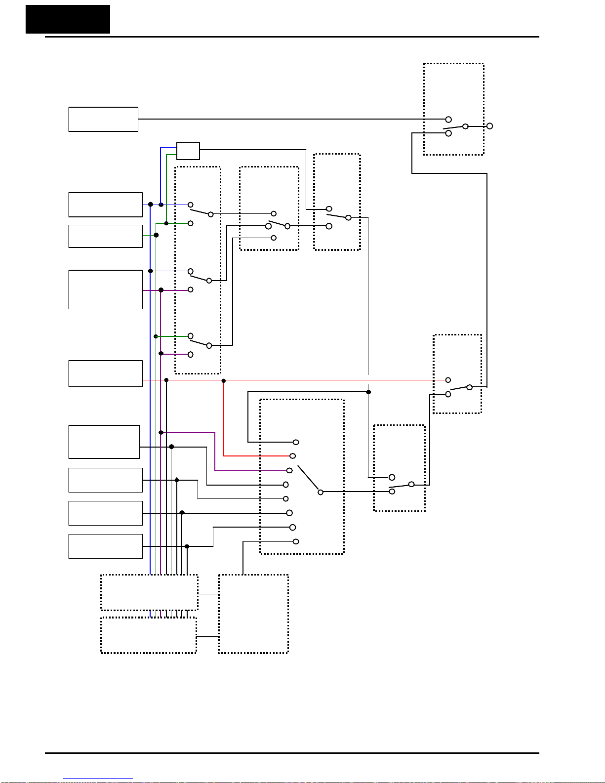
3−14
The figure below shows the correlation diagram of all frequency source setting methods and
their relative priority.
Note 1: You can set the inverter output frequency with function F001 only when you have specified “02”
for the frequency source setting
A001. If the setting of function A001 is other than “02”, function F001
operates as the frequency command monitoring function. And by setting the frequency set in monitoring
active (
b163=01), you can change the inverter output frequency with function d001 or d007.
[AT]
terminal
[AT]selection
A005
Multi-speed
inputs
CF1-4,SF1-7
Frequency
source setting
A001/A201
[AT]
terminal
is active
ON
OFF
[O]+[OI]
yes
no
01
02
00
03
04
06
07
10
ON
OFF
Force
terminal
mode
OFF
ON
Operator
control
Frequency
setting
ON
OFF
Multi-speed
A021-A035
Analog voltage
input [O]
OPE-SR/
OPE-SR mini
[VR]
Digital operator
A020/A220=F001
Modbu s
communication
Pulse train
input [EA]
EzSQ
Fr
equency calculate functio
n
00
02
03
ON
ON
OFF
OFF
B input select for
calculate function
A142
A Input select for
calculate function
A141
Calculation
symbol
A143
(+)
(-)
(×)
+
Option PCB
Analog current
input [OI]
1
∗
[AT]
terminal
[AT]selection
A005
Multi-speed
inputs
CF1-4,SF1-7
Frequency
source setting
A001/A201
[AT]
terminal
is active
ON
OFF
[O]+[OI]
yes
no
01
02
00
03
04
06
07
10
ON
OFF
Force
terminal
mode
OFF
ON
Operator
control
Frequency
setting
ON
OFF
Multi-speed
A021-A035
Analog voltage
input [O]
OPE-SR/
OPE-SR mini
[VR]
Digital operator
A020/A220=F001
Modbu s
communication
Pulse train
input [EA]
EzSQ
Fr
equency calculate functio
n
00
02
03
ON
ON
OFF
OFF
B input select for
calculate function
A142
A Input select for
calculate function
A141
Calculation
symbol
A143
(+)
(-)
(×)
+
Option PCB
Analog current
input [OI]
[AT]
terminal
[AT]selection
A005
Multi-speed
inputs
CF1-4,SF1-7
Frequency
source setting
A001/A201
[AT]
terminal
is active
ON
OFF
[O]+[OI]
yes
no
01
02
00
03
04
06
07
10
ON
OFF
Force
terminal
mode
OFF
ON
Operator
control
Frequency
setting
ON
OFF
Multi-speed
A021-A035
Analog voltage
input [O]
OPE-SR/
OPE-SR mini
[VR]
Digital operator
A020/A220=F001
Modbu s
communication
Pulse train
input [EA]
EzSQ
Fr
equency calculate functio
n
00
02
03
ON
ON
OFF
OFF
B input select for
calculate function
A142
A Input select for
calculate function
A141
Calculation
symbol
A143
(+)
(-)
(×)
+
Option PCB
Analog current
input [OI]
1
∗

3−15
Basic Parameter Settings
These settings affect the most fundamental behavior of the inverter – the outputs to the
motor. The frequency of the inverter’s AC output determines the motor speed. You may
select from three different sources for the reference speed. During application
development you may prefer using the potentiometer, but you may switch to an external
source (control terminal setting) in the finished application, for example.
The base frequency and maximum frequency settings interact according to the graph
below (left). The inverter output operation follows the constant V/f curve until it reaches
the full-scale output voltage at the base frequency. This initial straight line is the
constant-torque part of the operating characteristic. The horizontal line over to the
maximum frequency serves to let the motor run faster, but at a reduced torque. This is
the constant-power operating range. If you want the motor to output constant torque
over its entire operating range (limited to the motor nameplate voltage and frequency
rating), then set the base frequency and maximum frequency equal as shown (below
right).
NOTE: The “2nd motor” settings in the table in this chapter store an alternate set of
parameters for a second motor. The inverter can use the 1st set or 2nd set of
parameters to generate the output frequency to the motor.
“A” Function
Run
Mode
Edit
Defaults
Func.
Code
Name Description Lnitial data Units
A003
Base frequency Settable from 30 Hz to the
maximum frequency(A004)
Settable from 30 Hz to the 2
nd
maximum frequency(A204)
U
60.0 Hz
A203
Base frequency,
2nd motor
U
60.0 Hz
A004
Maximum frequency Settable from the base
frequency to 400 Hz
Settable from the 2nd base
frequency to 400 Hz
U
60.0 Hz
A204
Maximum frequency,
2
nd
motor
U
60.0 Hz
V
100%
A003
A004
0
Base
Frequency
Maximum
Frequency
f
V
100%
A003
A004
0
Base Frequency =
Maximum Frequency
f

3−16
Analog Input Settings
The inverter has the capability to accept an external analog input that can command
the output frequency to the motor. Voltage input (0-10 V) and current input (4-20mA)
are available on separate terminals ([O] and [OI] respectively). Terminal [L] serves as
signal ground for the two analog inputs. The analog input settings adjust the curve
characteristics between the analog input and the frequency output.
Adjusting [O-L] characteristics – In the
graph to the right, A013 and A014 select the
active portion of the input voltage range.
Parameters A011 and A012 select the start
and end frequency of the converted output
frequency range, respectively. Together,
these four parameters define the major line
segment as shown. When the line does not
begin at the origin (A011 and A013 > 0), then
A015 defines whether the inverter outputs
0Hz or the A011-specified frequency when
the analog input value is less than the A013
setting. When the input voltage is greater
than the A014 ending value, the inverter
outputs the ending frequency specified by
A012.
Adjusting [OI-L] characteristics – In the
graph to the right, A103 and A104 select the
active portion of the input current range.
Parameters A101 and A102 select the start
and end frequency of the converted output
frequency range, respectively. Together,
these four parameters define the major line
segment as shown. When the line does not
begin at the origin (A101 and A103 > 0), then
A105 defines whether the inverter outputs
0Hz or the A101-specified frequency when
the analog input value is less than the A103
setting. When the input voltage is greater
than the A104 ending value, the inverter
outputs the ending frequency specified by
A102.
If [AT] is not assigned to any of the intelligent input terminal, inverter recognizes the
input [O]+[OI].
Adjusting [VR-L] characteristics – This is used when an optional operator is used.
Refer to parameters A161 ~ A165 for the details.
Max frequency
A012
A011
A014
100%
0V
10V
A013
0%
A015=00
A015=01
0
Input scale
%
Max frequency
A102
A101
A104
100%
0
20mA
A103
0%
A105=00
A105=01
0
Input scale
%

3−17
“A” Function
Run
Mode
Edit
Defaults
Func.
Code
Name Description Lnitial data Units
A005
[AT] selection Three options; select codes:
00...Select between [O] and [OI]
at [AT] (ON=OI, OFF=O)
02...Select between [O] and
external POT at [AT]
(ON=POT, OFF=O)
03...Select between [OI] and
external POT at [AT]
(ON=POT, OFF=OI)
The output frequency
corresponding to the analog
input range starting point,
range is 0.00 to 400.0
U
00
−
A011
[O] input active range start
frequency
U
0.00 Hz
A012
[O] input active range end
frequency
The output frequency
corresponding to the analog
input range ending point,
range is 0.0 to 400.0
The starting point (offset) for
the active analog input range,
range is 0. to 100.
U
0.00 Hz
A013
[O] input active range start
voltage
U
0. %
A014
[O] input active range end
voltage
The ending point (offset) for the
active analog input range,
range is 0. to 100.
U
100. %
A015
[O] input start frequency
enable
Two options; select codes:
00…Use offset (A011 value)
01…Use 0Hz
U
01
−
A016
Analog input filter Range n = 1 to 31,
1 to 30 : ×2ms filter
31: 500ms fixed filter with ±
0.1kHz hys.
U
8. Spl.
A016: External Frequency Filter Time Constant – This filter smoothes the analog input
signal for the inverter’s output frequency reference.
・ A016 sets the filter range from n=1 to 30. This is a simple moving average calculation,
where n (number of samples) is variable.
・ A016=31 is a special value. It configures the inverter to use a movable deadband
feature. Initially the inverter uses the 500ms of filter time constant. Then, the
deadband is employed for each subsequent average of 16 samples. The deadband
works by ignoring small fluctuations in each new average: less than ±0.1Hz change.
When a 30-sample average exceeds this deadband, then the inverter applies that
average to the output frequency reference, and it also becomes the new deadband
comparison point for subsequent sample averages.
The example graph below shoes a typical analog input waveform. The filter removes
the noise spikes. When a speed change (such as level increase) occurs, the filter
naturally has a delayed response. Due to the deadband feature (A016=31), the final
output changes only when the 30-sample average moves past the deadband threshold.

3−18
TIP: The deadband feature is useful in applications that requires a very stable output
frequency but use an analog input for the speed reference. Example application: A
grinding machine uses a remote potmeter for operator speed input. After a setting
change, the grinder maintains a very stable speed to deliver a uniform finished surface.
EzSQ Related Settings
The WJ200 series inverter has capability to execute EzSQ program like SJ700 series
inverters. Parameters A017 is for the EzSQ performance. Please refer to the EzSQ
section for the detailed explanation.
Noise spikes
Speed increase given
A
nalog input
16-sample avg.
0
+0.1
-0.1
Threshold exceeded
Deadband
New deadband
0
+0.1
-0.1
Output freq.
reference
Hz
Small step change
t
A016=31

3−19
Multi-speed and Jog Frequency Setting
Multi-speed – The WJ200 inverter has the capability to store and output up to 16 preset
frequencies to the motor (A020 to A035). As in traditional motion terminology, we call
this
multi-speed profile
capability. These preset frequencies are selected by means of
digital inputs to the inverter. The inverter applies the current acceleration or
deceleration setting to change from the current output frequency to the new one. The
first multi-speed setting is duplicated for the second motor settings (the remaining 15
multi-speeds apply only to the first motor).
“A” Function
Run
Mode
Edit
Defaults
Func.
Code
Name Description Lnitial data Units
a019
Multi-speed operation
selection
Select codes:
00...Binary operation
(16 speeds selectable
with 4 terminals)
01...Bit operation (8 speeds
selectable with 7
terminals)
Defines the first speed of a
multi-speed profile, range is 0.0
/ start frequency to 400Hz
A020 = Speed 0 (1st motor)
U
00 -
A020
Multi-speed freq. 0
0.0 Hz
A220
Multi-speed freq. 0,
2
nd
motor
Defines the first speed of a
multi-speed profile or a 2nd
motor, range is 0.0 / start
frequency to 400Hz
A220 = Speed 0 (2nd motor)
Defines 15 more speeds,
range is 0.0 / start frequency to
400 Hz.
A021=Speed 1 ~ A035=Speed15
0.0 Hz
A021
to
A035
Multi-speed freq. 1 to 15
(for both motors)
See next
row
Hz
C169
Multistage speed/position
determination time
Set range is 0. to 200. (x 10ms)
U
0. ms
There are two ways for speed selection, that are “binary operation” and “bit operation”.
For binary operation (
A019=00), you can select 16 speeds by combination of 4 digital
inputs. And for bit operation (
A019=01), you can select 8 speeds by using 7 digital inputs.
Please refer to the following figures for detailed explanation.
 Loading...