

Page 1
1
Instruction Manual
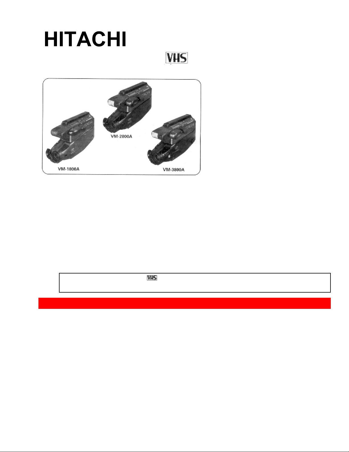
VM-1800A / VM-2800A / VM-3800A
Hitachi Home Electronics (America), Inc. HITACHI (HSC) CANADA
INC.
3890 Steve Reynolds Blvd., Norcross, GA 30093 3300 Trans Canada Hwy.,
Pointe Claire,
Tel. 404-279-5600 Quebec, H9R1B1, CANADA
Tel. 514-697-9150
HITACHI SALES CORPORATION OF HAWAII, INC.
3219 Koapaka Street, Honolulu, HI 96819
Tel. 808-836-3621
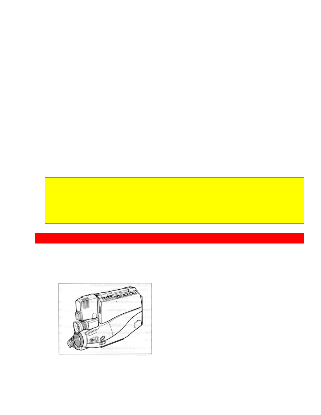
Thank you for choosing the
video camcorder. For maximum pleasure and
convenience please read these simple instructions before operating your camcorder.
CAUTIONS.................................................................................................................................................3
PRECAUTIONS .........................................................................................................................................5
FEATURES............................................................................................................................................5
ACCESSORIES....................................................................................................................................6
IMPORTANT SAFEGUARDS ..................................................................................................................6
IMPORTANT SAFETY INSTRUCTIONS FOR AC ADAPTER/CHARGER ......................................10
ELECTRONIC VIEWFINDER................................................................................................................11
POWER SOURCES..................................................................................................................................12
WHEN USING WITH THE BATTERY (Provided).....................................................................12
WHEN USING WITH THE AC ADAPTER/CHARGER (Provided)......................................... 13
1
Page 2

WHEN USING WITH THE CAR BATTERY (By using optional car battery cord Hitachi VM-
CC70A).................................................................................................................................................13
CHECKING THE BATTERY..................................................................................................................14
CHARGING A BATTERY ...................................................................................................................... 15
MAKING A SAMPLE RECORDING .....................................................................................................16
AUTOMATIC REWIND..........................................................................................................................19
IDENTIFICATION AND OPERATION OF CONTROLS .....................................................................19
DATE/TIME SETTING............................................................................................................................24
To correct date/time information after starting the date/time...................................................26
To correct date/time information during pro g r ammi ng.............................................................26
AUTOMATIC DATE RECORDING.......................................................................................................26
PROGRAM AE (Auto Exposure).............................................................................................................27
AUTO FOCUS..........................................................................................................................................27
The auto focus will not work under the following conditions. ..................................................28
MANUAL FOCUS (Only for VM-3800A) ..............................................................................................2 8
POWER ZOOM........................................................................................................................................29
DIGITAL ZOOM......................................................................................................................................29
X100 digital zoom (only for VM-3800A)......................................................................................30
INSTANT ZOOM (Only for VM-3800A)................................................................................................31
16:9 MODE (Only for VM-3800A)..........................................................................................................31
MACRO....................................................................................................................................................32
FADE IN / FADE OUT ............................................................................................................................32
Fading In..............................................................................................................................................33
Fading Out...........................................................................................................................................33
INDEX SIGNAL RECORDING .............................................................................................................. 34
QUICK EDIT (Edit Search)......................................................................................................................34
INSTANT REVIEW.................................................................................................................................35
TAPE COUNTER.....................................................................................................................................35
DISPLAY BUTTON.................................................................................................................................36
REMAINING TAPE.................................................................................................................................36
TITLE RECORDING ...............................................................................................................................37
Creating a title.................................................................................................................................37
Correcting errors during title storage...........................................................................................38
Recording titles on a tape in the camcorder..............................................................................39
Recording titles on another VCR while playing a tape back with the camcorder..................39
Chart of characters available in the titler....................................................................................39
USING THE WIRELESS REMOTE CONTROL (Only for VM-3800A)...............................................40
Loading Battery...................................................................................................................................40
Remote Controllable Range .............................................................................................................41
CONTROLLING YOUR TV WITH THE CAMCORDER'S REMOTE CONTROL (Only for VM-
3800A).......................................................................................................................................................42
Programming the Remote Control...................................................................................................42
Controlling the TV...............................................................................................................................43
RECORDING TV PROGRAMS..............................................................................................................43
AUDIO DUBBING................................................................................................................................... 44
AUDIO AND VIDEO DUBBING............................................................................................................46
VIEWING THE PICTURE PLAYED BACK ON YOUR TV ................................................................48
STILL........................................................................................................................................................50
FORWARD AND REVERSE SEARCH..................................................................................................50
MEMORY.................................................................................................................................................51
2
Page 3
CAUTIONS
CAMCORDER TO VCR DUBBING.......................................................................................................51
FLYING ERASE HEAD .......................................................................................................................... 52
ATTACHING THE OPTIONAL TELE OR WIDE CONVERTER LENS.............................................52
USING THE BUILT-IN CAMERA LIGHT (For VM-2800A/3800A)....................................................53
To replace the lamp of camera light................................................................................................54
EYEPIECE ADJUSTMENT..................................................................................................................... 55
VIEWFINDER BRIGHT, COLOR AND TINT CONTROLS (For VM-2800A/3800A)........................55
HOW TO ATTACH THE SHOULDER STRAP.....................................................................................56
TROUBLESHOOTING............................................................................................................................56
CLEANING THE INSIDE OF THE ELECTRONIC VIEWFINDER.....................................................58
For VM-1800A.................................................................................................................................58
For VM-2800A/3800A....................................................................................................................58
HEAD CLEANING ..................................................................................................................................59
PERIODIC MAINTENANCE..................................................................................................................59
SPECIFICATIONS...................................................................................................................................59
HOTLINE..................................................................................................................................................60
ACCESSORY TO ADD MORE EXCITEMENT....................................................................................61
HITACHI WARRANTY CARD (USA Back) .........................................................................................63
HITACHI WARRANTY CARD (Front) CANADA ONLY....................................................................64
HITACHI CANADA WARRANTY CARD (Back)................................................................................65
CAUTIONS
WARNING: TO PREVENT FIRE OR ELECTRIC SHOCK, DO NOT EXPOSE
THIS APPLIANCE TO RAIN OR MOISTURE.
CAUTION: TO REDUCE RISK OF ELECTRIC SHOCK, DO NOT REMOVE COVER (OR
BACK).
NO USER - SERVICEABLE PARTS INSIDE. REFER SERVICING TO QUALIFIED
SERVICE PERSONNEL.
This symbol warns the user that uninsulated voltage within the unit may
have sufficient magnitude to cause electric shock. Therefore, it is dangerous
to make any kind of contact with any inside part of this unit.
This symbol alerts the user that important literature concerning the
operation and maintenance of this unit has been included. Therefore, it
should be read carefully in order to avoid any problems.
3
Page 4

CAUTIONS
CAUTION:
TO PREVENT ELECTRIC SHOCK, MATCH WIDE BLADE OF PLUG TO W IDE SLOT ,
FULLY INSERT.
"This digital apparatus does not exceed the Class B limits for radio emissions from digital
apparatus as set out in the interference-causing equipment standard entitled " Digital
Apparatus", ICES-003 of the Department of Communications."
Warning: This device complies with Part 15 of the FCC rules. Operation is subject to the
following two conditions: (1) This device may not cause harmful interference, and (2) this
device must accept any interference received, including interference that may cause
undesired operation.
Note: This equipment has been tested and found to comply with the limits for a Class B
digital device, pursuant to Part 15 of the FCC Rules. These limits are designed to provide
reasonable protection against harmful interference in a residential installation. This
equipment generates, uses, and can radiate radio frequency energy and, if not installed
and used in accordance with the instructions, may cause harmful interference to radio
communications. However, there is no guarantee that interference will not occur in a
particular installation. If this equipment does cause harmful interference to radio or
television reception, which can be determined by turning the equipment off and on, the user
is encouraged to try to correct by one or more of the following measures:
--Reorient or relocate the receiving antenna.
--Increase the separation between the equipment and the receiver.
--Connect the equipment into an outlet on a circuit different from that to which the receiver
is connected.
--Consult the dealer or an experienced radio/TV technician for help.
Caution to the user: Changes or modifications not expressly approved by the
manufacturer could void the user's authority to operate the equipment.
Caution: Avoid operating your camcorder immediately after moving it from a cold area to a
warm humid area. Give the camcorder 2 to 3 hours to acclimate to the surroundings before
inserting a video cassette. When moved from a cold area to a warm humid area, moisture
may condense on the head drum inside the machine. This moisture could cause the tape to
stick to the headwheel and damage the headwheel or tape.
See the bottom of the AC adaptor/charger. The rating and caution label is located on the
bottom of the AC adaptor/charger.
WARNING: Many television programs and films are copyrighted. In certain circumstances,
copyright law may apply to private in-home videotaping of copyrighted materials.
4
Page 5

PRECAUTIONS
PRECAUTIONS
Any problems that occur as a result of any of the following conditions will not be covered
by our warranty.
Be careful that no water, dust, or sand enters the camcorder.
When you are not using the camcorder, switch off the power and attach the lens cap.
When you shoot at a scene which contains an extremely bright object such as the the
sun or a light source, a bright vertical bar may appear in the picture.
Your camcorder is functioning properly, but the solid-state pickup device (CCD) usually
causes this as an inherent characteristic. Try to avoid shooting an excessive bright
object directly.
Be sure not to leave the camcorder in a place where the temperature exceeds 140
deg. F (60 deg. C), or the pickup device may be damaged.
Dangerous includes:
Do not point the electronic viewfinder to direct sunlight; it could damage the
viewfinder.
The liquid crystal display (LCD) panel is made by highly precise technology. More
than 99.99% of its picture elements (pixels) are effective, but some (less than 0.01%)
may not appear as coloured bright dots. This does not indicate a fault as the LCD panel
stretches the limits of current technology. (for VM-2800A/VM-3800A)
FEATURES
Digital zoom up to X24
Digital zoom up to X100 (only for VM-3800A)
Solid-state camera pickup
High Quality picture technology
Auto focus power zoom lens with macro feature
Full record and playback capability with standard
Program AE (Auto Exposure)
Fade in / fade out
Color electronic viewfinder (EVF) (for VM-2800A/ VM-3800A)
Flying erase head
Time and date
Titler
Index signal
Audio / video dub
Audio dub
Built-in camera light (for VM-2800A/VM-3800A)
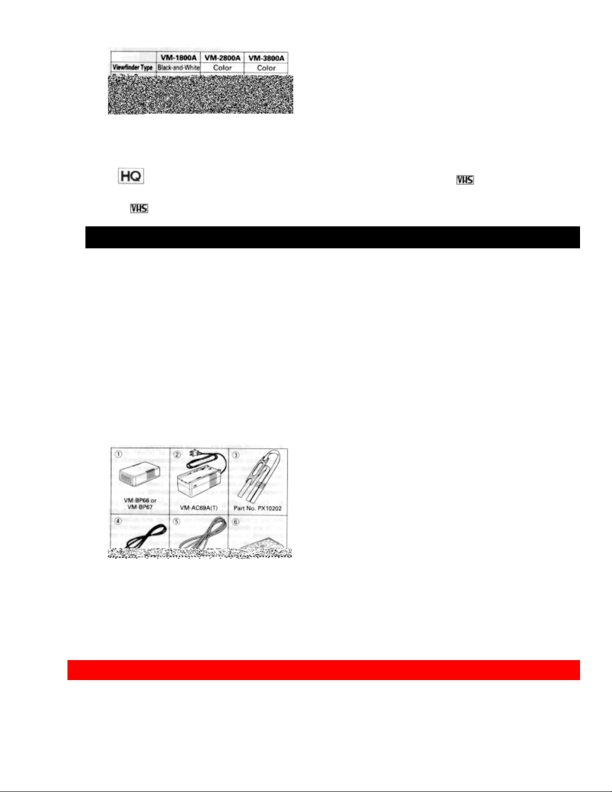
Differences between Models VM-1800A/2800A/3800A)
cassette
5
Page 6
IMPORTANT SAFEGUARDS
This instruction manual shows the illustrations for the VM-3800A.
* This video camcorder with this marking incorporates high-quality
picture technology and is compatible with any video cassette recorder bearing
the mark.
ACCESSORIES
Check to make sure you have the following components and accessories (besides the
camcorder unit itself) before disposing of the packing material.
1. Lead-acid rechargeable battery
VM-BP66 for VM-1800A/VM-2800A
VM-BP67 for VM-3800A
2. AC adaptor/charger
3. Shoulder strap
4. DC cord
5. Audio/video cable (only for VM-3800A)
6. Remote control (only for VM-3800A)
7. Remote control battery (only for VM-3800A)
IMPORTANT SAFEGUARDS
In addition to the careful attention devoted to quality standards in the manufacture of
6
Page 7
IMPORTANT SAFEGUARDS
your video product, safety is a major factor in the design of every instrument. But,
safety is your responsibility too.
This page lists important information that will help to assure your enjoyment and proper
use of a Video Camcorder and accessory equipment. Please read it carefully before
operating your video product and keep it in a handy place for future reference.
1 Read and Follow Instructions -- All the safety and operating instructions should be
read before the video product is operated. Follow all operating and use instructions.
2 Retain Instruction -- The safety and operating instructions should be retained for
future reference.
3 Heed Warnings -- Comply with all warnings on the video product and in the
operating instructions.
4 Polarized Plug -- This video product is equipped with a polarized alternating-current
line plug (a plug having one blade wider than the other). This plug will fit into the power
outlet only one way. This is a safety feature. If you are unable to insert the plug fully
into the outlet, try reversing the plug. If the plug should still fail to fit, contact your
electrician to replace your obsolete outlet. To prevent electric shock do not use this
polarized plug with an extension cord, receptacle or other outlet unless the blades can
be fully inserted without blade exposure. If you need an extension, use a polarized
cord.
INSTALLATION
5 Power Sources -- This video product should be operated only from the type of power
source indicated on the marking label. If you are not sure of the type of power supply to
your home, consult your video dealer or local power company. For video products
intended to operate from battery power, or other sources, refer to the operating
instructions.
6 Overloading -- Do not overload wall outlets and extension cords as this can result in
a risk of fire or electric shock. Overloaded AC outlets and extension cords are
dangerous, and so are frayed power cords, damaged or cracked wire insulation and
broken plugs. They may result in shock or fire hazard. Periodically examine the cord
and have it replaced by your service technician if appearance indicates damage or
deteriorated insulation.
7 Power Cord Protection -- Power supply cords should be routed so that they are not
7
Page 8

IMPORTANT SAFEGUARDS
likely to be walked on or pinched by items placed upon or against them, paying
particular attention to cords at plugs, convenience receptacles, and the point where they
exit from the appliance.
8 Ventilation -- Slots and openings in the cabinet are provided for ventilation to ensure
reliable operation of the video product and to protect it from overheating. These
openings must not be blocked or covered. The openings should never be blocked by
placing the video product on a bed, sofa, rug or other similar surface. This video
product should never be placed near or over a radiator or heat register. This video
product should not be placed in a built-in installation such as a bookcase or rack unless
proper ventilation is provided or the video product manufacturer's instructions have
been followed.
9 Attachments -- Do not use attachments unless recommended by the video product
manufacturer as they may cause hazards.
Caution: Maintain electrical safety. Power-line operated equipment or accessories
connected to this unit should bear the UL listing mark or CSA certification mark on the
accessory itself and should not have been modified so as to defeat the safety features.
This will help avoid any potential hazard from electric shock or fire. If in doubt, contact
qualified service personnel.
10 Water and Moisture -- Do not use this video product near water -- for example,
near a bath tub, wash bowl, kitchen sink, or laundry tub, in a wet basement, or near a
swimming pool, and the like.
11 Accessories -- Do not place this video product on an unstable card, stand, tripod,
bracket or table. The video product may fall, causing serious injury to a child or adult,
and serious damage to the appliance. Use only with a cart, stand, tripod, bracket or
table recommended by the manufacturer, or sold with the video product. Any mounting
of the product should follow the manufacturer's instructions, and should use a mounting
accessory recommended by the manufacturer.
11A An appliance and cart combination should be moved with care. Quick stops,
excessive force, and uneven surfaces may cause the appliance and cart combination to
overturn.
12 Outdoor Antenna Grounding -- If an outside antenna or cable system is
connected to the video product, be sure the antenna or cable system is grounded so as
to provide some protection against voltage surges and built-up static charges. Section
810 of the National Electrical Code, ANSI/NFPA No. 70, provides information with
respect to proper grounding of the mast and supporting structure, grounding of the lead-
8
Page 9

IMPORTANT SAFEGUARDS
in wire to an antenna discharge unit, size of grounding conductors, location of antennadischarge unit, connection to grounding electrodes, and requirements for the grounding
electrode. See example below:
EXAMPLE OF ANTENNA GROUNDING
13 Power Lines -- An outside antenna system should not be located in the vicinity of
overhead power lines or other electric light or power circuits, or where it can fall into
such power lines or circuits. When installing an outside antenna system, extreme care
should be taken to keep from touching or approaching such power lines or circuits as
contact with them might be fatal. Installing an outdoor antenna can be hazardous and
should be left to a professional antenna installer.
14 Cleaning -- Unplug this video product from the wall outlet before cleaning. Do not
use liquid cleaners or aerosol cleaners. Use a damp cloth for cleaning.
15 Object and Liquid Entry -- Never push objects of any kind into this video product
through openings as they may touch dangerous voltage points or short-out parts that
USE
9
Page 10

IMPORTANT SAFETY INSTRUCTIONS FOR AC ADAPTER/CHARGER
SERVICE
17 Servicing -- Do not attempt to service this video product yourself as opening or
removing covers may expose you to dangerous voltage or other hazards. Refer all
servicing to qualified service personnel.
18 Conditions Requiring Service -- Unplug this video product from the wall outlet and
refer servicing to qualified service personnel under the following conditions.
a. When the power-supply cord or plug is damaged
b. If liquid has been spilled or objects have fallen into the video product.
c. If the video product has been exposed to rain or water.
d. If the video product does not operate normally by following the operating instructions.
Adjust only those controls that are covered by the operating instructions. Improper
adjustment of o t her controls may result in damage and will often require extensive work
by a qualified technician to restore the video product to its normal operation.
e. If the video product has been dropped or the cabinet has been damaged.
f. When the video product exhibits a distinct change in performance -- this indicates a
need for service.
19 Replacement Parts -- When replacement parts are required, have the service
technician verify that the replacements he uses have the same safety characteristics as
the original parts. Use of replacements specified by the video product manufacturer can
prevent fire, electric shock or other hazards
20 Safety Check -- Upon completion of any service or repairs to this video product, ask
the service technician to perform safety checks recommended by the manufacturer to
determine that the video product is in safe operating condition.
21 Heat -- The product should be situated away from heat sources such as radiators,
heat registers, stoves, or other products (including amplifiers) that produce heat.
IMPORTANT SAFETY INSTRUCTIONS FOR AC ADAPTER/CHARGER
1. Save these instructions--This page contains important instructions for AC
Adaptor/Charger Model VM-AC69A (T).
2. Before using AC Adaptor/Charger, read all instructions and cautionary markings on
(1) AC Adaptor/Charger, (2) battery and (3) product using battery.
3. Also read all instructions on pages 4 and 5.
4. Caution--To reduce the risk of injury, charge only rechargeable battery, VMBP64/BP65/BP66/BP67. Other types of batteries may burst causing personal injury and
damage.
5. Do not expose charger to rain or snow.
6. Use of an attachment not recommended or sold by the battery charger manufacturer
may result in a risk of fire, electric shock, or injury to persons.
7. To reduce the risk of damage to electric plug and cord, pull by plug rather than cord
10
Page 11
ELECTRONIC VIEWFINDER
when disconnecting charger.
8. Make sure cord is located so that it will not be stepped on, tripped over, or otherwise
subjected to damage or stress.
9. Do not operate charger with damaged cord or plug--replace them immediately.
10. An extension cord should not be used unless absolutely necessary.
Use of improper extension cord could result in a risk of fire and electric shock. If
extension cord must be used, make sure:
A. That the pins on plug of extension cord are the same number, size, and shape as
those of plug on charger.
B. That extension cord is properly wired and in good electrical condition; and
C. That wire size should be met below:
Minimum AWG size Length of extension cord (feet)
18 Equal to or less than 100
16 Equal to or less than 150
11. Do not operate charger if it has received a sharp blow, been dropped, or otherwise
damaged in any way; take it to a qualified serviceman.
12. Do not disassemble charger; take it to a qualified serviceman when service or repair
is required. Incorrect reassembly may result in a risk of electric shock or fire.
13. To reduce the risk of electric shock, unplug charger from outlet before attempting
any maintenance or cleaning.
"Note to CATV system installer: This reminder is provided to call the CATV system
installer's
attention to Article 820-40 of the NEC that provides guidelines for proper grounding and, in
particular, specifies that the cable ground shall be connected to the grounding system of
the building,
as close to the point of cable entry as practical".
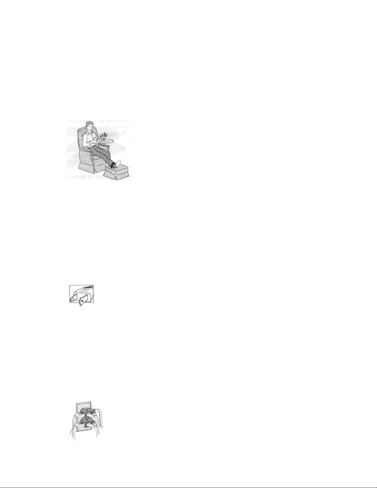
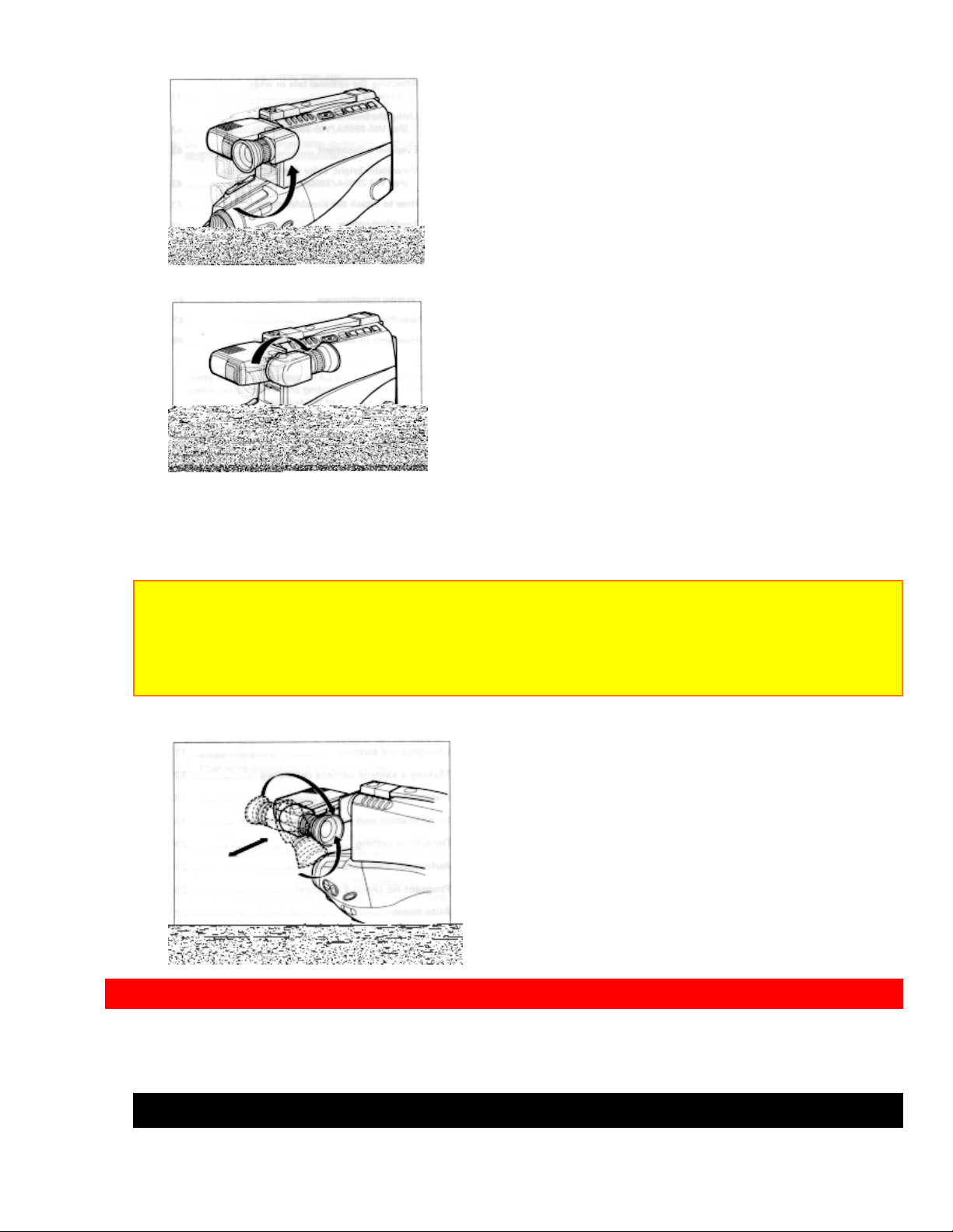
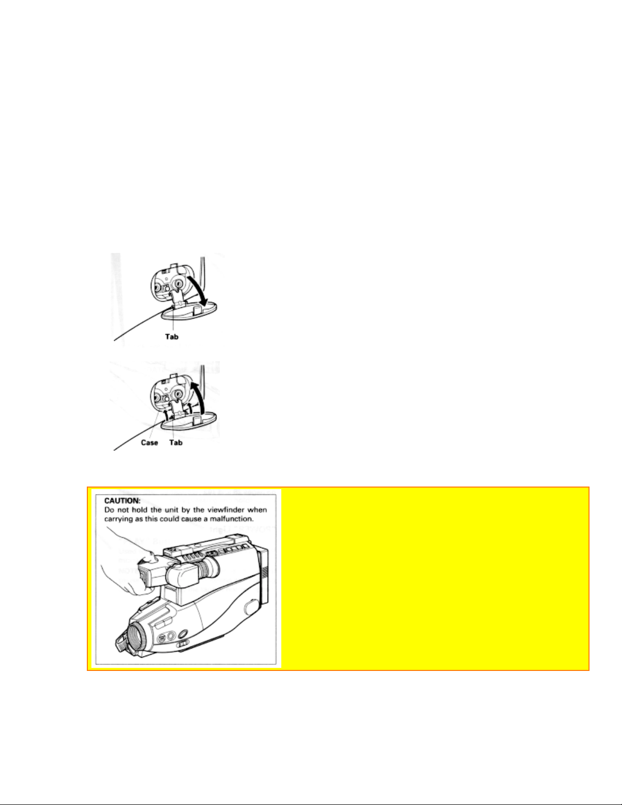
ELECTRONIC VIEWFINDER
Set the viewfinder to the position shown in the figure when carrying the camcorder or
storing it in the carrying case.
Turn the viewfinder to the position shown below when shooting pictures.
1. Turn the viewfinder
11
Page 12
POWER SOURCES
2. Turn the eyepiece.
You can adjust the position and angle of the viewfinder so you can see through it
easily.
Cautions:
Do not force the viewfinder to rotate completely around. This will damage the viewfinder
and/or camcorder.
When pulling the viewfinder out or returning it to its original position, hold the viewfinder
by the swivel selection. Do not hold the diopter control side.
POWER SOURCES
WHEN USING WITH THE BATTERY (Provided)
12
Page 13
POWER SOURCES
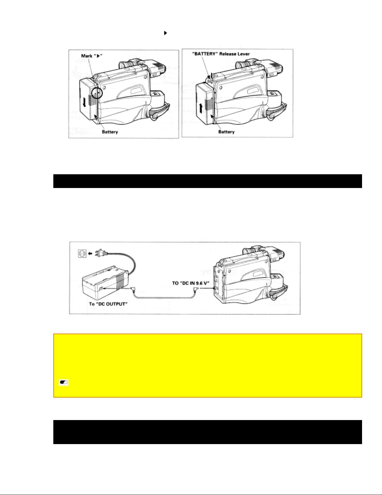
To attach, align the mark " " of the battery with that of the camcorder so that the
battery fits into the groves, and slide the battery downward, as illustrated.
To remove the battery:
Push and hold "Battery" release lever, then slide the battery to the upside and remove.
WHEN USING WITH THE AC ADAPTER/CHARGER (Provided)
1. Plug the AC adaptor/charger power cord into AC electrical outlet.
2. Connect one end of the DC cord (provided) to the "DC IN 9.6V" of the AC
adaptor/charger.
Connect the other end of the DC cord to the "DC OUTPUT" of the AC adaptor/charger.
NOTES:
The AC adaptor/charger cannot charge the battery and operate the camcorder at the
same time.
When using the AC adaptor/charger to power the camcorder, the batter level indicator
may display
" ". This indicator is used for battery operation and has no meaning when using the AC
adaptor/charger to power the camcorder.
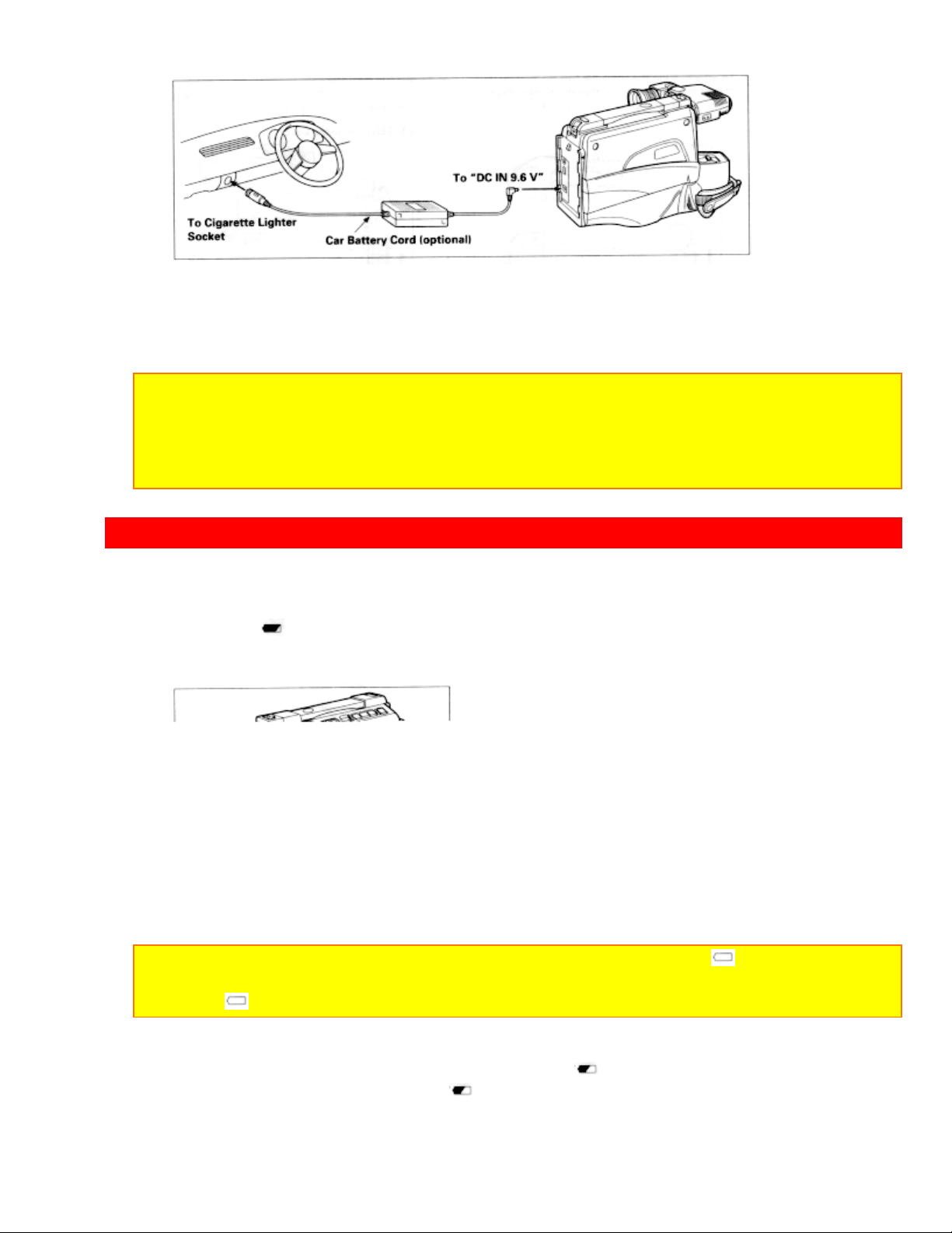
WHEN USING WITH THE CAR BATTERY (By using optional car battery
cord Hitachi VM-CC70A)
13
Page 14
CHECKING THE BATTERY
1. Connect the small plug of the car battery cord to the "DC IN 9.6V" jack of the
camcorder.
2. Connect the other end of the car battery cord to the car's cigarette lighter socket.
NOTES:
The car battery cord is designed to be used only with automobiles having a 12-volt
negative ground system.
To prevent fire or shock hazard or damage to your camcorder, please use only the
specified car battery cord.
CHECKING THE BATTERY
When the " " indication appears in the viewfinder and flashes while the camcorder is
being operated with a battery (provided), it indicates that the battery charge is low.
Charge it or replace it with a charged battery.
NOTE: When the camcorder is turned on, the battery level indicator " " is displayed in the
viewfinder indicating the condition of camera/recording battery. When the battery is fully
charged, " " is displayed.
After several minutes, the symbol will change to " ". When the battery is very near
empty, the symbol will change to " " and start blinking. You should find an alternative
power source or recharge the battery before continuing to use your camcorder.
14
Page 15
CHARGING A BATTERY
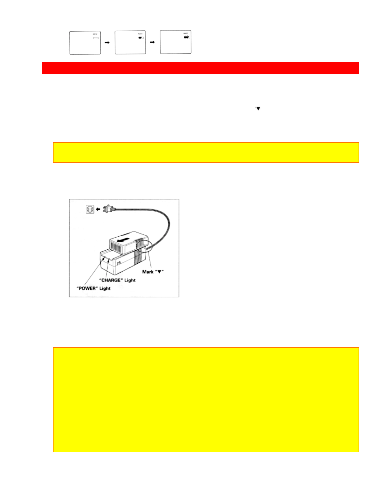
CHARGING A BATTERY
2
1. Plug the AC adaptor/charger power cord into AC electrical outlet.
2. Attach the battery to the AC adaptor/charger. Align the mark " " on the battery with that of
AC adaptor/charger and push the battery flush with the AC adaptor/charger and slide it in the
direction of arrow.
NOTE: You must remove the DC cord from the AC adaptor/charger to charge the battery. If
the DC cord is connected, "CHARGE" light will not light.
3. The "CHARGE" light will be lit while the battery is accepting a charge, and will go out
when the battery is fully charged.
Charging Time and Operation Time
VM-BP66 VM-BP67
Charging Time about 2 hours about 3 hours
Operation Time about 1 hour about 2 hours
NOTES:
1. The operation time depends on how often you use zoom and recording pause.
2. Charge the battery after each use and store it at normal room temperature.
3. Recharge the battery at least once every six months. The battery is a lead-acid battery.
This battery tends to discharge if not used for an extended period of time. If the battery is
stored for an extended length of time without being recharged, you may not be able to
recharge it.
4. A battery charged after being stored for a long period may not supply power for the
specified time. Additional rechargings will help restore the battery's operation time.
5. The battery should be charged at a temperature of 50 ºF--86ºF (10ºC--30ºC) to prevent
damage.
6. Do not operate the battery at temperatures below 14ºF (-10ºC) or above 95ºF (35ºC).
15
Page 16

MAKING A SAMPLE RECORDING
The battery may be damaged if operated at temperatures above 122ºF (50ºC). Operation
time will decrease at extremely low temperatures.
7. After repeated chargings and use, the operation time will gradually decrease. When
operation time becomes too short to be useful, it is time to replace the battery.
8. If "CHARGE" and "POWER" lights on the AC adaptor/charger start flashing, remove the
battery and then reattach it. If after several attempts both lights continue to flash, this
means your battery cannot take a charge and must be replaced with a new one.
The "CHARGE" light will not go light if a hot battery is attached to the AC adaptor/charger.
Attaching an extremely hot battery to the adaptor/charger is not recommended; it should be
allowed to cool down before being attached.
9. Do not short the battery's terminal.
10. Do not attempt to disassemble or modify the battery. There are no user serviceable
parts inside.
11. Throwing the battery into a fire or exposing the battery to excessive heat -- over 149ºF
(65ºC) could be hazardous.
12. Be sure to set the "POWER" switch to the "OFF" position before removing the battery.
ATTENTION:
The product that you have purchased contains a rechargeable battery. The battery is
recyclable. At the end of its useful life under various state and local laws, it may be illegal to
dispose of this battery into the municipal waste stream. Check with your local solid waste
officials for details in your area for recycling options or proper disposal.
MAKING A SAMPLE RECORDING
1. Connect the POWER SOURCE. (See pages 9 and 10.)
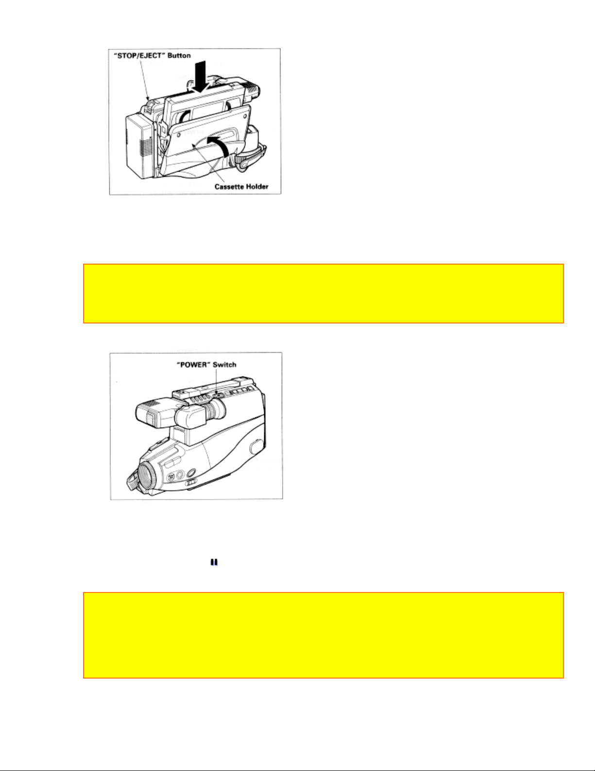
2. Press "STOP/EJECT" button and insert the cassette so the transparent window is
toward you and the arrow toward the cassette holder. Slide the cassette into cassette
holder as far as it will go.
NOTE: Push in the center of the cassette all the way until it is latched by the cassette
holder.
3. Press the cassette holder. The holder will latch in the operating position.
16
Page 17
MAKING A SAMPLE RECORDING
4. Press and hold the small button on "POWER" switch, and then slide it to the "CAM"
position. The "POWER" indicator will light and the camcorder will enter record/pause
mode automatically.
NOTES:
If the erase prevention tab on the cassette is removed, the "TAPE" indication in the
viewfinder flasher for several seconds and the camcorder will not enter record/pause mode.
See page 43 for "EYEPIECE ADJUSTMENT".
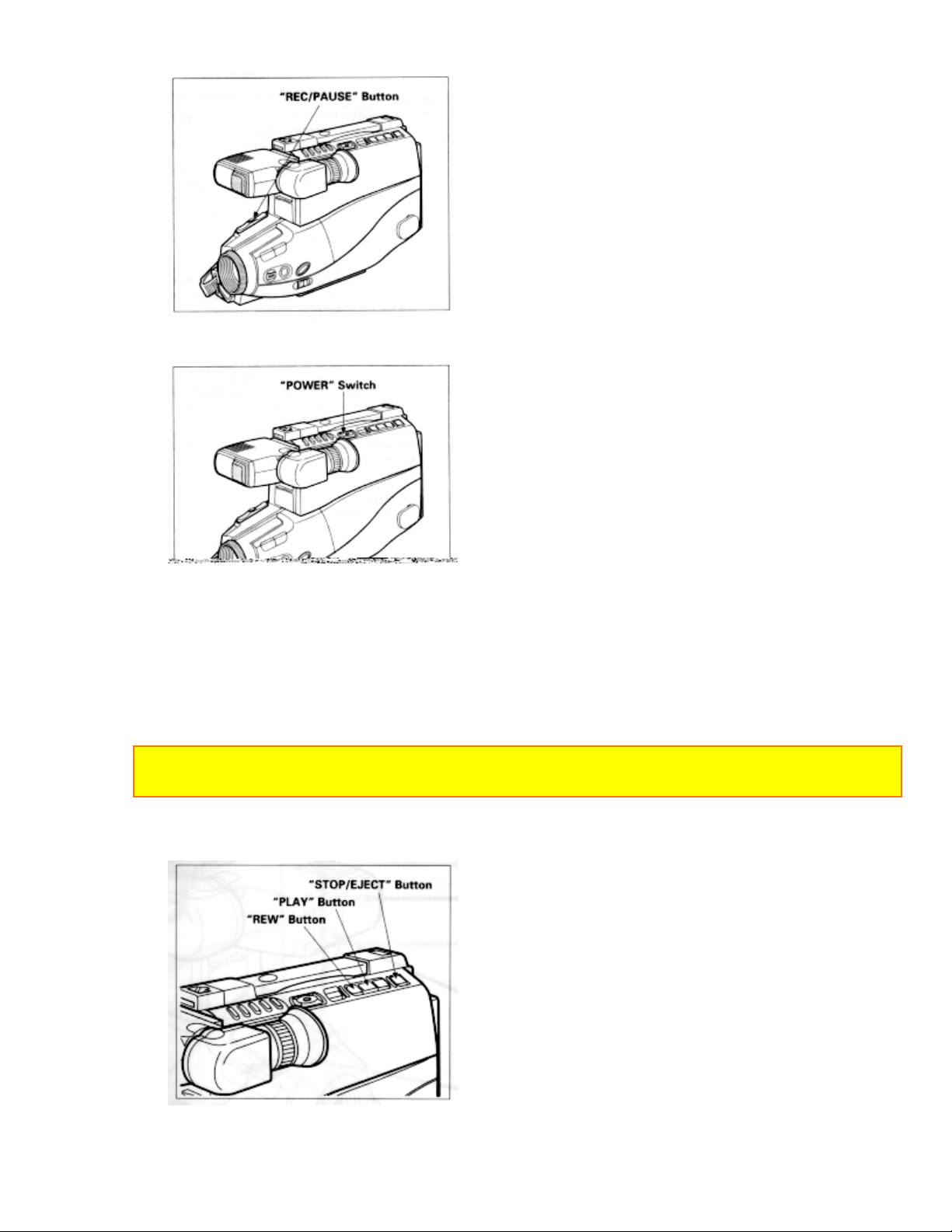
5. Now, press "REC/PAUSE" button to start shooting the picture. The "REC" indication
appears in the viewfinder and you are now recording the picture you see through the
viewfinder.
6. Press "REC/PAUSE" button to stop recording. Press the button again to resume
recording. The "
" indication will appear in the viewfinder instead of "REC" while
the camcorder is in the record/pause (stand-by) mode.
NOTES:
The "TAPE END" indication starts flashing in the viewfinder when there is about five
minutes recording time left on the cassette.
If the record/pause mode continues for more than 5 minutes, the camcorder's power is
automatically turned off. To turn on again, press "REC/PAUSE" button. The camcorder
enters record/pause (stand-by) mode.
17
Page 18
MAKING A SAMPLE RECORDING
7. After recording, press and hold the small button on the "POWER" switch, and then
slide it to "VIDEO". The camcorder will now be in the stop mode.
8. Press "REW" button. The tape will be rewound to the beginning
9. Press "PLAY" button. The picture you just recorded will be seen through the
viewfinder.
NOTE: If you connect the camcorder to your TV, you can see the picture played back on
your TV. Refer to "VIEWING THE PICTURE PLAYED BACK ON YOUR TV" on page 38.
10. After playing, press "STOP/EJECT" button
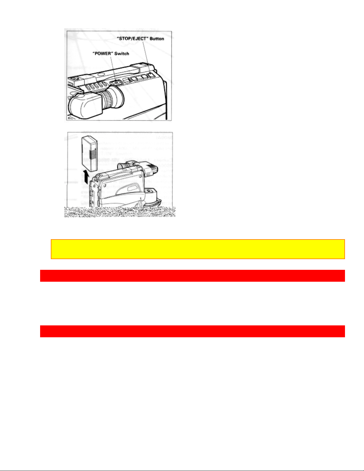
11. Slide the "POWER" switch to "OFF" position to turn off the camcorder. Press
"STOP/EJECT" button to remove the cassette.
18
Page 19
AUTOMATIC REWIND
12. Always remove the power source from the camcorder after use.
NOTE: If you have a cassette tape that has already been partially recorded on and you
want to record the remaining blank section, see "QUICK EDIT" on page 27.
AUTOMATIC REWIND
When the tape reaches its end during playback, it automatically rewinds to the
beginning and stops.
IDENTIFICATION AND OPERATION OF CONTROLS
Diagram of camera
Diopter Control (for VM-2800A/3800A)
Use this control to focus the viewfinder.
See page 19 for VM-1800A's diopter control
Camera Light (for VM-2800A/3800A)
When the "POWER" switch is in the "CAM" position, the camera light is turned on and
19
Page 20

IDENTIFICATION AND OPERATION OF CONTROLS
off automatically or manually in the record and record/pause modes depending on the
position of "LIGHT" switch. Turn the camera light off after use.
NOTE: The camera light turns on only in the record and record/pause modes.
Microphone
Sensitive to sounds coming from the direction in which the camera is pointed.
3
"FOCUS" Control (AUTO/MAN) Button (only for VM-3800A)
Press these buttons simultaneously to select manual or automatic focus. For manual focusing,
press the or button to bring the subject into focus. When using manual focus, "FOCUS"
appears in the viewfinder.
4
Lens (with Lens Cap)
F1.6 (4~48 mm) 12:1 power zoom lens features auto focus and auto iris functions.
Infrared Ray Receiving Section (only for VM-3800A)
Receives infrared rays from the remote control.
"FADE" Button
During recording you can add a professional touch to your recordings by fading in and
out of scenes. You can select three fade modes -- the white fade, wipe fade, and zoom
fade.
NOTE: W hen you fade scenes in and out, the sound will also fade in and out with the
picture. (See page 26.)
"INST.ZOOM" (Instant Zoom) Button (only for VM-3800A)
Use this button to magnify the image being recorded 1.5 times.
"ZOOM MODE" Button (only for VM-3800A)
Use this button to zoom in on a subject up to a magni ficati on of about 100 or chang e the
picture format (aspect ratio) from 4:3 (the picture format of an ordinary TV set) to 16:9.
"LIGHT" Switch (for VM-2800A/3800A)
When this switch is set to "AUTO", the camera light turns on or off automatically
according to the brightness of the object. When the switch is set to "ON", the camera
light turns on. Set the switch to "OFF" to turn the light off manually.
Electronic Viewfinder (EVF)
Displays what the camcorder lens sees. The electronic viewfinder also functions as a
convenient monitor during playback of recorded material.
"AV OUT/IN" Switch
This switches the "AUDIO" and "VIDEO" jacks between the input and the output. When
20
Page 21
IDENTIFICATION AND OPERATION OF CONTROLS
the switch is set to "OUT", the "AUDIO" and "VIDEO" jacks can be used as output
jacks, and when the switch is set to "IN", they can be used as input jacks.
"RF DC OUT" Jack
Connect the RF converter unit (optional) to this jack.
5
"AUDIO/VIDEO" Jacks
These can be used as input or output jacks depending on the position of "AV OUT/IN" switch.
When using these jacks as outputs, connect the audio/video cable (supplied only with the
VM-3800A) to these jacks and to the audio and video inputs of your TV/monitor receiver. You
can also connect the RF converter unit (optional) to these jacks and your TV receiver.
Use these jacks as inputs when you supply signals from another device to your camcorder
for recording.
To open the cover:
To close the cover, first hook the onto the case.
Diagram of Buttons
"TITLE" Button
21
Page 22

IDENTIFICATION AND OPERATION OF CONTROLS
Press this button to create and record personalized titles on you r videos with the
camcorder's built-in titler.
(See "TITLE RECORDING" on page 29.)
"DATE / TIME" Button
Press this button to display the date and time in the viewfinder.
Whenever the date and time appear in the viewfinder, they will be recorded on the tape.
"RESET" Button
When the linear time counter is displayed in the viewfinder, pressing this button resets
the counter to "0000".
"REVIEW" Button
Used to review the last few seconds of the recorded seg ment in the r ecor d/pause mode.
(See "INSTANT REVIEW" on page 27.)
"DISPLAY" Button
If this button is pressed, "M" appears beside the tape counter in the viewfinder and the
tape's position is stored in memory. If the camcorder is connected to a TV/monitor
receiver, the same display as that in the viewfinder appears on the screen when the "M"
is displayed.
(See "DISPLAY BUTTON" and "MEMORY" on pages 28 and 40.)
"POWER" Light
"POWER" Switch
This switch changes the camcorder to the record mode or to the playback mode.
Press and hold the small button on this switch, and then slide it to "CAM" or "VIDEO".
"DUBBING AUDIO/VIDEO" Button
This button is used to record new audio in place of existing audio without erasing the
video. See page 35.
This button is used to record new video in place of existing video and audio. See
page 36.
"REW" Button
Press this button during stop or fast forward mode, and rewinding starts. "
" appears
in the viewfinder. Press the button during playback of tape, and the tape is played back
in the rewind direction approximately 3 times faster than the normal speed to confirm
the recorded contents.
Press "PLAY" button to return to normal playback mode or press "STOP/EJECT"
button to stop tape movement.
NOTE: You can also visually scan backward when the camcorder is in record/pause
(stand-by) mode by pressing and holding this button.
22
Page 23

IDENTIFICATION AND OPERATION OF CONTROLS
"STOP/EJECT" Button
The "STOP/EJECT" button is used to stop playback, rewind, and fast forward
operations. The "STOP/EJECT" button has no effect during record operation.
This button is used in the stop mode to open the cassette holder.
"F.FWD" Button
Press this button during stop or rewind mode, and fast-forwarding starts. "
" appears
in the viewfinder.
Press the button during playback of tape, and the tape is played back in the forward
direction approximately 3 times faster than the normal speed to confirm the recorded
content.
Press "PLAY" button to return to normal playback mode or press "STOP/EJECT"
button to stop tape movement.
NOTE: You can also visually scan forward when the camcorder is in record/pause (standby) mode by pressing and holding this button.
"PLAY" Button
Used for playback of tape recorded in the SP mode.
NOTE: When the camcorder is in the record/pause (stand-by) mode, pressing and holding
this button will play the tape at normal speed.
(REW, PLAY, F.FWD, and STOP/EJECT)
These buttons are used for title making buttons when the "TITLE" button is pressed.
(See "TITLE RECORDING" on page 29.)
These buttons may be also used to set the date and time during pause (stand-by)
mode. (See "DATE/TIME SETTING" on page 20.)
Camera Diagram
"BATTERY" Release Lever
Releases the battery attached to the video camcorder.
Cassette Holder
Press "STOP/EJECT" button in the stop mode to open the cassette holder. Be awar e of
the cassette direction when inserting.
NOTE: Power source must be connected to open the cassette holder.
"DC IN 9.6V" Jack
When using t he AC adaptor/charger (provided) or the car battery cord (optional), connect t his
jack and the "DC OUTPUT" of t he AC adapt er /charger or the car's cigarette lighter sock et.
23
Page 24

DATE/TIME SETTING
Graphics in the Electronic Viewfinder
"BRIGHT', "COLOR" and "TINT" controls (for VM- 2800A/3800A)
Use to adjust the picture color in the viewfinder. See page 43.
"REC/PAUSE" Button
This button is used to control the camcor der . When this button is pressed with the camcorder
set to the recording mode, the t ape runs to start recording. "REC" appears in the viewfinder.
When this but t on is pr essed again, "
camcorder enters the record/pause (stand-by) mode.
" appears instead of band the tape stops and the
NOTE: This button may be also used to display a still picture during the playback mode.
Power Zoom Switch/ "TRACKING" Control
This switch performs zooming electr ically.
"W": Picture becomes wider gradually.
"T": Picture becomes telescopic gradually.
Used when playing a tape recorded on another VCR. Adjust for best picture. Ejecting the
cassette returns the track ing to the normal position.
Lens Cap Tab
Place the lens cap on this tab when you are ready to record a scene. The tab also prevents
the lens cap from swinging around on tits cor d.
For VM-1800A (click to see illustration)
"BRIGHT" and "FOCUS" Controls
Use to a
24
Page 25

DATE/TIME SETTING
NOTES:
The backup battery should be charged every two months. If it is not charged periodically,
it will be over-discharged and its life will be shortened.
A cassette cannot be loaded or ejected when setting the date and time.
1. Press and hold the small button on "POWER" switch, and then slide it to "CAM"
position.
2. Press "DATE/TIME" button.
Date and time appear in the viewfinder and "1" flashes.
3. Press "F.FWD" button to select correct month. Hold button down to advance rapidly.
If you go past the month you want to set, press "REW" button. When the correct month
appears, press "STOP/EJECT" button.
4. Press "F.FWD" button to select correct date. Hold button down to advance rapidly. If
you go past the date you want to set, press "REW" button. When the correct date
appears, press "STOP/EJECT" button.
5. Press "F.FWD" or "REW" button to select year, and then press "STOP/EJECT"
button.
6. Press "F.FWD" or "REW" button as many times as may be required to select the
correct hour, and then press "STOP/EJECT" button.
7. Repeat step 6 to select minute and AM/PM.
25
Page 26

AUTOMATIC DATE RECORDING
8. After setting AM or PM, press "DATE/TIME" button to change the display and start
the internal clock. It is recommended that you press "DATE/TIME" button to match the
time signal.
9. Press "DATE/TIME" button after setting the clock. The d isplay will change as follows
each time the button is pressed.
NOTE: The date/time graphics will be recorded whenever they appear in the viewfinder.
To correct date/time information after starting the date/time
1. Press and hold "DATE/TIME" button, and then press "STOP/EJECT" button. The
month starts flashing.
2. Correct the incorrect digit by using "F.FWD", "REW" and "STOP" buttons.
To correct date/time infor mation during programming
Press "STOP/EJECT" button repeatedly until the digit that is incorrect flashes. Correct
the incorrect digit by using "F.FWD", "REW" and "STOP/EJECT" buttons.
AUTOMATIC DATE RECORDING
This feature records the date automatically once a day. After you begin recording, the
date is recorded automatically for 10 seconds. The same date is recorded again in the
following cases.
When the cassette is replaced.
When "
When the recording is for less than 10 seconds.
26
" is displayed again after being switched to the date display.
Page 27

PROGRAM AE (Auto Exposure)
If the date changes while recording continues over 10 seconds, the date is recorded for
10 seconds when recording is restarted after the camcorder has been set to the standby
mode.
Press "DATE/TIME" button until " " and the date appear in the viewfinder before
you begin to record. The date will be recorded whenever it appears in the viewfinder.
PROGRAM AE (Auto Exposure)
Program AE automatically selects the shutter speed 1/60, 1/100, 1/120, 1/180, 1/250,
1/350, 1/500, 1/750, 1/1000, 1/1500, 1/2000 or 1/4000 second that is optimum for the
brightness of the subject. The iris is also adjusted automatically in response to the
shutter speed.
AUTO FOCUS
The camcorder focuses the subject in the center of the viewfinder automatically.
NOTE for VM-3800A: If "FOCUS" appears in the viewfinder, manual focus is engaged.
Press the FOCUS control (AUTO/MAN) buttons simultaneously to return to auto focus.
27
Page 28

MANUAL FOCUS (Only for VM-3800A)
The range of the object with which auto focus can be used.
On "T" side: about 3.3 feet (1m) from the lens surface to infinity.
On "W" side: about 0.4 inches (1 cm) from the lens surface to infinity.
The auto focus will not work under the following conditions.
1. Objects not in the center of the viewfinder.
2. Objects at far and near positions at the same time.
3. Objects lit by a spotlight or neon signs, etc.
4. Objects behind glass with water droplets or dust on it.
5. Objects with almost no difference in brightness such as a white wall.
6. Objects moving rapidly.
7. Dark objects.
MANUAL FOCUS (Only for VM-3800A)
1. Press the FOCUS control (AUTO/MAN) buttons simultaneously. "FOCUS" appears
in the viewfinder. You can adjust the focus manually.
2. Use the power zoom T control to zoom up completely to your subject. If you don't use
the T control to zoom to the picture you want, the picture may fall out of focus when
actual recording starts.
3. Pressing the FOCUS control (AUTO/MAN) (far) or (near) button until the subject
is in focus.
4. Use the power zoom W control to zoom back to the picture you desire.
28
Page 29

POWER ZOOM
NOTE: To return to auto focus press the FOCUS control (AUTO/MAN) buttons and
"FOCUS" disappears from the viewfinder.
POWER ZOOM
Press power zoom switch on the "W" side, and the picture gradually widens.
Press the power zoom switch on the "T" side, and the picture gradually becomes
telescopic.
The zooming speed is slow when the power zoom switch is pressed lightly, and the
zooming speed is fast when the switch is pressed strongly.
When power zoom switch is operated, the zoom position is displayed in the
viewfinder in 10 steps for several seconds.
DIGITAL ZOOM
29
Page 30

DIGITAL ZOOM
The digital zoom increases the magnification of the power zoom by 2 times. You must
place the subject you wish to magnify at the center of the viewfinder. Press and hold the
power zoom T control until you find the picture you want. You control the zoom with the
power zoom T and W controls. When "ZOOM" is not displayed in the viewfinder, normal
zoom functions resume.
NOTE: When the digital zoom is used, the more the image is magnified, the rougher the
picture becomes. Also even a slight shaking of the camcorder is conspicuous.
X100 digital zoom (only for VM-3800A)
This feature allows the image to be magnified up to about 100 times. Press the "ZOOM
MODE" button to display "ZM:2", and then press and hold the power zoom T control
until you reach your desired magnification. Each time the "ZOOM MODE" button is
pressed, the display in the viewfinder will change as follows. You can use the X100
digital zoom feature when "ZM:2" is displayed.
After using the X100 digital zoom feature, press the "ZOOM MODE" button so that
"ZM:2" is no longer displayed in the viewfinder.
30
Page 31

INSTANT ZOOM (Only for VM-3800A)
NOTES:
When digital zoom is used, the more the image is magnified, the coarser the picture
becomes. Also even slight shaking of the camcorder is conspicuous.
When "16:9" is displayed in the viewfinder, the picture format is switched from 4:3 to
16:9. See "16:9 MODE" on page 25.
INSTANT ZOOM (Only for VM-3800A)
The instant zoom feature activates the digital zoom to magnify the subject 1.5
regardless of zooming engaged by the power zoom T and W controls. Press the INST.
ZOOM button. "I.ZOOM" appears in the viewfinder and the picture is magnified 1.5
times.
NOTES:
To return to the original zoom position, press the INST. ZOOM button so that "I.ZOOM"
disappears from the viewfinder.
When the instant zoom is used, the more the image is magnified, the rougher the picture
becomes. Also even slight shaking of the camcorder is conspicuous.
16:9 MODE (Only for VM-3800A)
The picture format can be switched from 4:3 (the picture format of an ordinary TV set) to
16:9. Press the "ZOOM MODE" button twice to display "16:9"; the top and bottom of
the picture in the viewfinder become black bars. After using the 16X9 mode, press the
"ZOOM MODE" button so that "16:9" is not displayed in the viewfinder and restore the
the normal picture.
31
Page 32

MACRO
MACRO
6
Allows you to shoot objects as close as 0.4 inches (1 cm) from the lens tip.
Press and hold "W" side of power zoom switch. An object is auto focused.
NOTES:
Determine the size of the object by moving the camera backward and forward.
Be careful as the lighting may tend to be insufficient when shooting in the above
conditions.
FADE IN / FADE OUT
Use the fade feature t o add a pr ofessional touch to your recordings. Use the FADE button to
select one of the three fade options.
White fade: Fades in from a white screen or fades out to a white screen. "
" appears in the
32
Page 33

FADE IN / FADE OUT
upper left corner of the viewfinder.
Wipe f ade: The picture opens gradually from the center of a black screen or closes into the
center to a black screen. "
Zoom fade: Fades in while zooming from a white screen or fades out while zooming to a
white screen. "
" appears in the upper left corner of the viewfinder.
" appears in the upper left corner of the viewfinder.
Fading In
1. Use the FADE button to select a fade option before recording.
2. Press the "REC/PAUSE" button to start recor ding: fade then begins automatically.
Fading Out
1. While re cor ding with the camcorder use the FADE button to select option.
2. Press the "REC/PAUSE" button to stop recording ; the fade begins automatically and "REC"
flashes until the fade ends.
NOTE: When fading out be sure to wait until the PAUSE indicator ( ) is visible in the viewfinder
before attempting t o pit the camcorder into the record mode again.
33
Page 34

INDEX SIGNAL RECORDING
INDEX SIGNAL RECORDING
7
Indexing your tapes while recording makes it easy to find desired program segments when
you play back the tape in a VCR that has a compatible indexing feature called the "VHS Index
Search System". See your VCR's instruction manual for index playback instructions.
"INDEX" signals are recorded when the following operations are performed.
When power is turned on about 4 hours after it is switched off and then recording is started.
When power is turned on after the date is changed to the next day with the power off and
then recording is started.
NOTE: "INDEX" is displayed in the viewfinder, and when an "INDEX" signal is recorded,
"INDEX" disappears.
QUICK EDIT (Edit Search)
The quick edit feature allows you to search for the end of previously recorded material,
or find a particular spot on your tape, to begin your editing, or recording new material.
Quick edit is used while the camcorder is in the record/pause (stand-by) mode. By
holding down the "F.FWD", "REW", or "PLAY" button, you can visually search or play
your tape. Releasing the buttons ("F.FWD", "REW", or "PLAY") immediately stops the
34
Page 35

INSTANT REVIEW
tape at that position.
INSTANT REVIEW
1. In record/pause (stand-by) mode, press "REVIEW" button, and the last few seconds
of the recorded scene is played back in the reverse direction and then played back in
the forward direction.
2. When the tape reaches the end of the scene you have just recorded, the camcorder
returns to the record/pause (stand-by) mode. Recording starts again when the
"REC/PAUSE" button is pressed again.
TAPE COUNTER
Load a cassette into the camcorder and perform recording or playback; the counter
indicates the amount of tape transported as a 4-digit number.
NOTES:
The tape counter does not operate when nothing is recorded on the tape.
Counter changes to 0000 when cassette is ejected.
35
Page 36

DISPLAY BUTTON
DISPLAY BUTTON
Each time the "DISPLAY" button is pressed, the display in the viewfinder switches as
follows.
When the tape counter with memory is displayed in the viewfinder, the same display
appears on the screen of the connected TV/monitor receiver.
REMAINING TAPE
The tape remaining display shows the remaining tape that can be used for recording
and playback, using seven dashes. This feature is handy when recording since it lets
you know how long you can record on the loaded tape.
Insert a cassette in the camcorder and start recording or playback; 10 seconds later, the
remaining tape will be displayed. When the cassette is ejected, the display will
36
Page 37

TITLE RECORDING
disappear. " " is displayed for 10 seconds after the tape starts to run.
NOTE: When the remaining recording tape time becomes less than about five minutes,
"TAPE END" flashes in the viewfinder.
TITLE RECORDING
You can easily create and record personalized titles on your videos with the
camcorder's built-in titler. The titler will store 2 dif ferent title pages in memory. Once a
title is stored, it can be displayed and recorded at any time. Each title page can contain
two lines of 16 characters each. The titler contains 47 different characters for creating
titles.
NOTE: A cassette cannot be loaded or ejected when creating a title.
Creating a title
1. Attach a power source to the camcorder and slide "POWER" switch to either "CAM"
or "VIDEO" position.
2. Press "TITLE" button. The flashing cursor will appear in the viewfinder.
37
Page 38

TITLE RECORDING
3. Press "SHIFT" button repeatedly to move the flashing cursor to the place you want to
begin your title.
4. Select the first character for your title by pressing the "-" or "+" button repeatedly
until the desired character appears.
NOTE: Each title can contain up to two lines of 16 characters each. A chart showing the
characters contained in the titler is located on page 30.
5. After you have selected the first character, press "SHIFT" button to move the flashing
cursor to the place you want the next character.
6. Repeat steps 4 and 5 until you have completed the title.
NOTE: Character may flash, however it will be recorded correctly without flashing.
7. After completing your title, press "PAGE" button and create the title on another page.
8. After creating the title, press "TITLE" button to remove the title graphics from the
viewfinder. Now title graphics is stored in memory.
NOTE: As long as the correct current time can be displayed, the title is held in memory.
Correcting errors during title storage
1. Press "Shift" button repeatedly until the character to be corrected will flash.
2. Press either "-" or "+" button until the correct character appears.
NOTE: The correct character may flash, however it will be recorded correctly without
flashing.
38
Page 39

TITLE RECORDING
Recording titles on a tape in the camcorder
1. Slide "POWER" switch to "VIDEO".
2. Locate the position on the tape that you wish to record the title.
3. Set "POWER" switch to "CAM".
4. Press "TITLE" button to display the title graphics.
5. Press "PAGE" button until the title you wish to record appears in the viewfinder.
6. Press "REC/PAUSE" button to start the title recording.
7. Press "TITLE" button to remove the title graphics from the viewfinder. The
camcorder will now record as normal.
NOTE: If you are planning to video tape an event you must prepare your titles in advance,
then by pressing "TITLE" button superimpose the title over the scene as it's being
recorded. You cannot go back and record titles over existing video without erasing the
previously recorded material.
Recording titles on another VCR while playing a tape back with the
camcorder
1. Connect the camcorder and VCR. (See page 41.)
2. Select the title you wish to record from page 1 or p age 2. The la st title selected will
appear first. Press "TITLE" button to turn title off.
3. Set the VCR in the recording mode and camcorder in the playback mode.
4. Press "TITLE" button when you see the scene where you want to record the title.
5. Press "TITLE" button to erase the display from the viewfinder.
Chart of characters available in the titler
39
Page 40

USING THE WIRELESS REMOTE CONTROL (Only for VM-3800A)
A B C D E F G H I J K L M N O P Q R S T U V W X Y Z 0 1 2 3 4 5 6 7 8 9 ? ' . / , - ; : <
> ! (blank)
USING THE WIRELESS REMOTE CONTROL (Only for VM-3800A)
Use the wireless remote control to operate the camcorder from a distance.
(1) TV Control Buttons
Used for controllin g the TV.
POWER: Turns the TV on and of f.
AVX: Used for recording picture and sound from an auxiliary input.
VOLUME: Increase ( ) or decrease ( ) the volume.
CHANNEL: Top ( ) button switches to the next higher channel, bottom ( ) button
switches to the next lower channel. For these to operate, you must have preset your
channels.
(See CONTROLLING YOUR TV WITH THE CAMCORDER'S REMOTE CONTROL " on
page 33.)
(2) Camcorder Control Buttons
These buttons on the remote control have the same functions as the corresponding
buttons on the camcorder.
NOTE: The zoom switch on the remote control cannot change the zoom speed, but
provides only low-speed zooming.
Loading Battery
1. Push the tab to the right of the remote control and hold it; then remove the battery holder.
40
Page 41

USING THE WIRELESS REMOTE CONTROL (Only for VM-3800A)
2. Press the PLAY button and hold it for about two seconds.
3. Insert the battery with the positive (+) t erminal facing up.
4. Replace the battery holder with battery in the remote control making sure that it is fully
inserted.
WARNING: KEEP THE BATTERY AWAY FROM CHILDREN AND PETS. IF SWALLO WED
CONSULT A PHYSICIAN IMMEDIATELY FOR EMERGENCY TREATMENT.
NOTES:
Replace remote control battery with 3V micro lithium cells such as Maxell CR2025 or its
equivalent.
Dispose of battery safely in accordance with local laws. Do not dispose of in fire.
Do not short circuit the battery.
Do not take apart the batter y.
Do not hold the battery with the metallic tweezers.
Do not recharge the battery.
Keep the battery in a dark, cool, dry place.
Remote Controllable Range
NOTES:
Use the wireless remote control within the range of the infrared ray receiver of the camcorder
shown above.
41
Page 42

CONTROLLING YOUR TV WITH THE CAMCORDER'S REMOTE CONTROL (Only for VM-3800A)
The wireless remote control may not funct ion in strong light such as direct sunlight or very bright
artificial lighting .
Clear a path from the wireless remote cont rol to the infrared ray receive. The wireless remote
control won't work if an obstacle blocks t he infrared rays.
The remote control code of t his cam c or der is Hitachi code 8VCRs that have "CAM" mode
button.VCR2. If you have a VCR with the same code as your Hitachi VCR may malfunction when
you use the camcorder's wireless remote control control.
CONTROLLING YOUR TV WITH THE CAMCORDER'S REMOTE CONTROL (Only for VM3800A)
The remote control is designed to be compatible with many televisions, but it will not
work with every one made. If your TV does not respond the way it should when you
program it as explained below, this remote may be incapable of operating it. Once you
have programmed the remote, you won't have to do it again until you change the
battery.
This remote control can be used with your TV as well as the camcorder, as long as your
TV comes with a remote control. This feature comes in handy - you don't have to juggle
two remotes.
The remote control is compatible with the fourteen makers of TVs listed below - but
don't be alarmed if yours is not on our list. You may still be able to program the remote
for your TV.
Every TV that comes with a remote control is set up to detect certain infrared signals.
You need to program the camcorder remote control to send signals that your TV will
recognize and respond to. Here's what to do:
Programming the Remote Control
Turn the television on (any channel is okay).
Aim the camcorder's remote control at your TV set. Hold down the CH(
while you press the button corresponding to your brand of television as shown in the
chart.
For example, if you have an RCA television, press CH(
) and display at the same time.
If this button combination sends a signal that matches with your TV, the channel will
change on the TV, and you'll know the remote is set to control the television.
If that button combination does not change the TV channel, go through the whole list
of button combination one by one until you find one that does change your TV channel.
Also, if your brand of TV is not listed in the chart, try all the buttons. One of them may
work for you. If the TV still doesn't change after going through all the button
combinations listed, it is likely that you will not be a b le to program this remote control for
your TV.
TV Brands Press CH(
) and this button
Hitachi AVX
42
) button
Page 43

RECORDING TV PROGRAMS
Zenith VOL( )
Sony ZOOM.(W)
Magnavox REW
Sanyo PLAY
Goldstar1 F.FWD
Toshiba AV DUB
Goldstar 2 STOP
NEC PAUSE (START/STOP)
RCA DISPLAY
Panasonic TITLE ON/OFF
Mitsubishi ZOOM.(T)
JVC COUNTER RESET
Sharp REVIEW
Controlling the TV
Once programmed, the camcorder's remote control is ready to control the TV.
Press the button of the TV function that you want.
Be aware that not all of your TV's functions may work even though the remote control is
correctly programmed.
NOTES:
It may not be possible to control all TVs listed in this table.
The AVX button can't be used with Goldstar 2 and Sharp TVs.
RECORDING TV PROGRAMS
If your TV or VCR has output jacks, you can record the TV program with camcorder.
43
Page 44

AUDIO DUBBING
1. Connect the audio/video cable to "AUDIO OUT" and "VIDEO OUT" of your TV and
VCR.
2. Connect the other end to "AUDIO" and "VIDEO" of camcorder.
3. Insert the cassette.
NOTE: Power source must be connected to the camcorder.
4. Set "AV OUT/IN" switch to "IN" position.
5. Press and hold the small button on "POWER" switch, and then slide it to "CAM"
position. The "POWER" indicator will light.
6. Turn on your TV or VCR and tune it to the channel you wish to record.
7. Press "REC/PAUSE" button to start recording. You are now recording the TV
program.
8. Press "REC/PAUSE" button to stop recording.
9. After recording, place "POWER" switch in "OFF" and then press "STOP/EJECT"
button to remove the cassette.
AUDIO DUBBING
44
Page 45

AUDIO DUBBING
The audio dubbing feature lets you record new audio (sound) on a previously recorded
tape without erasing the original video.
When you audio dub a tape, the previous audio is erased and replaced with new sound.
NOTES:
Sound from the built-in microphone and the AUDIO jack can be dubbed.
When dubbing audio from the built-in microphone, set "AV OUT/IN" switch to "OUT" and
do not connect the "AUDIO" jack. When dubbing audio from the "AUDIO" jack, set the
"AV OUT/IN" switch to "IN".
1. Insert a recorded tape. Be sure that the record safety tab is not missing.
2. Place "POWER" switch to "VIDEO" position.
3. Play the tape and press "REC/PAUSE" button where you want to dub audio.
The camcorder enters the still play mode.
4. Press "DUBBING AUDIO/VIDEO" and "PLAY" buttons at the same time.
"A.DUB " appears in the viewfinder.
NOTE: If "DUBBING AUDIO/VIDEO" and "PLAY" buttons are pressed twice, audio and
video dubbing will start. In this case, press "STOP/EJECT" button to release the dubbing
mode.
5. Press "RECORD/PAUSE" button to start audio dubbing.
6. Press "STOP/EJECT" button to stop audio dubbing.
NOTE: If counter memory "M" appears in the viewfinder, the tape stops automatically at
the reading of "0000" and audio dubbing stops.
45
Page 46

AUDIO AND VIDEO DUBBING
AUDIO AND VIDEO DUBBING
9
The audio and video dubbing feature lets you record new audio (sound) and video (pictures)
simultaneously on a previously recorded tape.
When you audio and video dub a tape, the previous audio and video are erased and replaced with the
new sound and pictures. The replacement audio and video can be the sound and picture taken by the
camera or from a video source connected to "AUDIO" and "VIDEO" jacks on the camcorder.
NOTE: When dubbing the sound and picture from a video source, set "AV OUT/IN" switch
to "IN" position. When dubbing the sound and picture from the camera, set "AV OUT/IN"
switch to "OUT" and do not connect "AUDIO" and "VIDEO" jacks.
1. Insert a recorded tape. Be sure that the record safety tab is not missing.
2. Place "POWER" switch in "VIDEO" position.
3. Press "PLAY" button and then "REW" or "F.FWD" button to search to the
approximate position of the tape on which you want to dub sound and picture.
4. Press "PLAY" button again to search the exact position where you wish to stop
dubbing and then press "REC/PAUSE" button at the exact position.
46
Page 47

AUDIO AND VIDEO DUBBING
5. Press "RESET" button to set the counter reading to "0000".
6. Press "DISPLAY" button so counter memory "M" appears.
7. Press "REW" button to rewind the tape to the approximate position from which you
want to start dubbing.
8. Press "PLAY" button, and when the exact position to start dubbing is reached, press
"REC/PAUSE" button.
9. Press "DUBBING AUDIO/VIDEO" and "PLAY" buttons simultaneously twice. "AV
DUB ||" is displayed in the viewfinder, and at the same time the picture to be dubbed
appears.
10. Press the "REC/PAUSE" button. Dubbing will start and will stop when the counter
reads "0000".
47
Page 48

VIEWING THE PICTURE PLAYED BACK ON YOUR TV
VIEWING THE PICTURE PLAYED BACK ON YOUR TV
To play back a tape recorded on your camcorder and view it on your TV receiver, you
must connect the camcorder to the TV receiver using either audio/video cable (supplied
only with VM-3800A) or RF converter unit (optional).
You also may play back the tape recorded by your camcorder on any other VHS video
cassette recorder. The camcorder records and plays back in VHS standard speed (SP).
A tape recorded in long play (LP) or extra long play (EP) cannot be played back on this
camcorder.
Example 1: If your TV has "VIDEO IN" and "AUDIO IN " jacks,
1. Connect the audio/video cable to "AUDIO IN" and "VIDEO IN" of your TV.
2. Connect the other end of the audio/video cable to "AUDIO" and "VIDEO" of your
camcorder.
3. Turn on your TV.
4. Set "AV OUT/IN" switch to "OUT" position.
5. Press "STOP/EJECT" button on the camcorder and then insert the cassette.
6. Place "POWER" switch in "VIDEO" position.
7. Press "PLAY" button.
8. After playing press "STOP/EJECT" button.
Tracking adjustment
When playing prerecorded tapes or tapes recorded by the recorders other than your
48
Page 49

VIEWING THE PICTURE PLAYED BACK ON YOUR TV
own, black and white streaks may appear on your TV screen. If this occurs, press
"TRACKING" control (W or T) until the streaks disappear. When the cassette is
ejected, the tracking is reset to normal.
Example 2: If you have a VHS VCR,
1. Insert the recorded tape into your VCR.
2. Press "PLAY" button of your VCR.
NOTE: W hen noise appears in the played back picture, adjust "TRACKING" control on the
VCR so there is no noise.
Example 3: If your TV is a regular TV,
Diagram of Hookup
1. Disconnect the VHF antenna leads from the rear of the TV receiver.
NOTE: Leave the UHF antenna leads connected to the TV.
2. Connect the VHF antenna lead to "IN FROM ANT" on the RF converter unit. If the
cable is round (75 Ohm), it will connect directly to the "IN FROM ANT". If it is the flat
type, (300 Ohm), connect it to the antenna adaptor (300 Ohm to 75 Ohm) and slip the
adaptor on to the "IN FROM ANT" terminal.
3. Connect the 75 Ohm coaxial cable with antenna adaptor to "OUT TO TV" on the RF
converter unit.
4. Connect the other end to the VHF antenna terminal on the TV, as illustrated.
5. Connect the connector cable from RF converter unit to "RF DC OUT", "AUDIO", and
"VIDEO" jacks on the camcorder.
6. Turn on the TV and set to channel 3 unless channel 3 is one of the TV stations in
your area. If channel 3 is used in your area, set your TV to channel 4.
7. Set the RF channel selector on the RF converter unit to "CH3" or CH4" to match the
channel selector on your TV.
8. Perform same procedures in steps 4 through 8 of "Example 1".
49
Page 50

STILL
NOTE: If you want to watch a TV program with camcorder connected as illustrated, slide
"POWER" switch of the camcorder to "OFF".
STILL
When "REC/PAUSE" button is pressed during playback, a still picture can be seen. To
start again press "REC/PAUSE" button and playback will be resumed.
NOTE: There will be some noise (interference) in the still picture.
FORWARD AND REVERSE SEARCH
When you press "F.FWD" or "REW" button during playback, the tape will be played
back at a speed about 3 times faster than normal playback speed, and you can easily
locate a certain spot on the tape. Press "PLAY" button to return to normal playback
mode or press "STOP/EJECT" button to stop tape movement.
NOTE: There will be some noise (interference) in the forward or reverse search pictures
while visually scanning.
50
Page 51

MEMORY
MEMORY
When the tape counter with memory indication appears in the viewfinder, a tape that is
being rewound automatically stops when the counter reads approximately "0000". This
is useful if there is a section of tape you want to review immediately after recording or if
you want to return to the same point several times in a row.
1. Press "DISPLAY" button. (The indicator "M" appears beside the tape counter.)
2. Start playing or recording a tape.
3. At the point you want playback to start, press "RESET" button to reset the counter to
"0000M".
4. Continue to play back or record.
5. Press "STOP/EJECT" button to stop playback, or press "REC/PAUSE" button to
stop recording and place "POWER" switch in "VIDEO" position.
6. Press "REW" button. The tape will be rewound to the preselected point, at
approximately "0000M" indication.
NOTE: The tape will also stop approximately at "0000M" during fast forward mode.
CAMCORDER TO VCR DUBBING
51
Page 52

FLYING ERASE HEAD
If you wish to exchange or copy some of your friend's favorite home recordings, the
following instructions can be used to connect camcorder to VCR for this purpose.
1. Connect the audio/video cable to "AUDIO" and "VIDEO" of your camcorder.
2. Connect the other ends to "AUDIO IN", "VIDEO IN" of your VCR as shown in the
diagram above.
3. Set "AV OUT/IN" switch to "OUT" position.
4. Play the tape on the camcorder and record it on the VCR.
NOTE: If you connect the "VHF OUT TO TV" connector of VCR to the "TV ANT"
connector, as illustrated and set VCR to "VCR" mode, the picture being dubbed by VCR
can be monitored.
FLYING ERASE HEAD
A rotating erase head which eliminates glitches and rainbow noise that occurs at the
joints between recorded segments.
ATTACHING THE OPTIONAL TELE OR WIDE CONVERTER LENS
1. To remove the lens hood, turn it counterclockwise as shown in the figure.
52
Page 53

USING THE BUILT-IN CAMERA LIGHT (For VM-2800A/3800A)
2. Remove both caps of the telephoto or wide angle lens.
3. Screw the lens into the threads on the front of camcorder lens assembly.
USING THE BUILT-IN CAMERA LIGHT (For VM-2800A/3800A)
Use the built-in camera light it you wish to shoot objects in dark places. When the
"LIGHT" switch is set to "AUTO", the camcorder light turns on automatically when the
camcorder is pointed at objects in a dark place and turns off when it is pointed at
objects in a bright place.
CAUTION: The power consumption of the built-in camera light is about a half that of the
camcorder. Therefore, if the camera light is turned on when a fully charged battery pack is
attached, the operating time of the battery falls to about a half.
1. Make sure that a fully charged battery pack or AC adaptor/charger is attached.
2. Set the "POWER" switch to "CAM" and then set the "LIGHT" switch to "AUTO"
when required.
NOTE: When the "LIGHT" switch is set on "ON", the camera light will turn on whenever
you make a recording.
CAUTIONS:
Turn the camera light on only when you need it, otherwise the operating time of the
battery pack is shortened due to the power consumption of the camera light.
When the "LIGHT" switch is set to "AUTO", the camera light does not turn on unless a
cassette is loaded.
CAUTION: Do not hold the unit by the built-in camera light when carrying as this could
cause a malfunction.
53
Page 54

USING THE BUILT-IN CAMERA LIGHT (For VM-2800A/3800A)
3. After use, set the "LIGHT" switch to "OFF" or set the "POWER" switch of the
camcorder to "OFF" position.
CAUTION:
During operation and/or aft er use of the camera light, the front surf ace and lam p of the camera
light will be very hot. To avoid burns or hair damage, do not t ouch t hem with your hand.
When the cam er a light is on, do not allow water to drop on the light.
When the camera light is on, avoid subjecting the camera light to impacts or sharp vibrations.
Do not allow the cooling vents to become blocked. Also, do not cover the camera light with paper
or other objects, since the air flow will be interrupted, result ing in possible overheating hazard.
Never use the camera light in the vicinity of explosive or highly inf lam m able m aterials.
After using the camer a light, cool the camera light section sufficiently befor e storing the
camcorder in the case.
Replace only with the specified lamp (optional) to reduce the risk of fire.
To replace the lamp of camera light
To remove the front case, press and hold the tab, then remove the front case.
To replace the front case, pass the lamp through the hole of the reflection plate then
attach the upper hooks to the camera light, and then attach the lower hook to the
camera light.
54
Page 55

EYEPIECE ADJUSTMENT
NOTES:
Do not touch the lamp directly with your fingers. It may shorten its service life.
When the lamp is replaced, or when the front case of the camera light is removed, make
sure the front case is attached to the camera light properly.
Consult your nearest service center to replace the lamp.
EYEPIECE ADJUSTMENT
To use the electronic viewfinder without eyeglasses on, adjust the diopter control for
optimum focus adjustment.
VIEWFINDER BRIGHT, COLOR AND TINT CONTROLS (For VM-2800A/3800A)
You can adjust the viewfinder brightness, color and tint as required.
"BRIGHT" Control
Viewfinder brightness can be adjusted by turning the "BRIGHT" control. This does not
affect the picture actually recorded by the camcorder.
"COLOR" and "TINT" Controls
The small "COLOR" and "TINT" controls are set at the factory and should require no
adjustment. If they ever require adjustment, use a plastic screwdriver. Make the
adjustments with caution to prevent damaging the miniature controls.
55
Page 56

HOW TO ATTACH THE SHOULDER STRAP
HOW TO ATTACH THE SHOULDER STRAP
Attach the shoulder strap (provided), as illustrated.
TROUBLESHOOTING
Your camcorder is a highly sophisticated instrument. It has been carefully checked and
adjusted at the factory under the most rigid quality control and inspection systems.
However, should problems develop, check the following points and take the necessary
corrective measures.
INSERTING OR REMOVING THE CASSETTE
Symptom Check Point & Correction
Cassette holder cannot be opened
Connect the power source.
when you slide “EJECT” button
Cassette cannot be inserted into
cassette compartment.
Load cassette in direction indicated by
arrow on cassette.
Cassette window must be toward
outside.
56
Page 57

TROUBLESHOOTING
CAMERA RECORDING
Symptom Check Point & Correction
Picture does not appear in the
Remove the lens cap.
viewfinder.
`Slide the power switch to
“CAMERA”
Disconnect the AV input cable from
the camera/recorder.
The camera/recorder cannot go into
the recording mode, even when the
Check the record protect tab on the
cassette.
start/stop button is pressed.
Make sure that the “FOCUS M” does
not appear in the viewfinder. If it is
displayed, press “Focus” select
button to erase it.
Picture is out of focus. Auto-Focus does not operate if a
special effects filter is attached.
NO OPERATION IS ACCEPTED
Symptom Check Point & Correction
Power is turned on, but no button operations are Remove the power source,
accepted. and after about one minute,
push the reset switch gently
using a toothpick, etc. until
you feel a click. Since this
erases the date, time and
other customer preferred
features, reset them again.
PLAYBACK OF PRE-RECORDED CASSETTE
Symptom Check Point & Correction
"PLAY" button cannot be engaged. Set the "POWER" switch to
"VIDEO" position. No picture
appears on television screen when Set the television to the "PLAY" is pressed.
Camera/recorder channel
(3 or 4) depending upon the
selected channel on
(TV is connected to the camera/recorder RF channel select switch by
using RF converter unit.) of RF converter unit. Set
"AV IN/OUT" switch to
57
Page 58

CLEANING THE INSIDE OF THE ELECTRONIC VIEWFINDER
"OUT" position. Interference on playback picture.
Adjust the tracking using
"TRACKING" control
(power zoom switch).
When you see the playback
picture on your TV, adjust
fine tuning knob on television
set to obtain best picture.
The pre-recorded tape is EP
or LP recording. This
camera/recorder is for use in
SP recording only. Picture bends at the top of the TV
screen. TV receiver is older type. It
needs to be modified to work
properly with
camera/recorder.
Tape is damaged. Try another
cassette.
Color of your TV screen is too bright, too faint or TV set has VIR circuit. Turn
off during playback.change.
CLEANING THE INSIDE OF THE ELECTRONIC VIEWFINDER
For VM-1800A
If dust or foreign matter adheres inside the viewfinder, clean it by
using the follow i ng procedure.
1. Push the tab and hold it, then open the cover,
2. Clean the picture tube face and lens. To prevent scratching, use a
soft non abrasive cloth, swab or lens cleaning paper.
3. Close the cover.
For VM-2800A/3800A
58
Page 59

HEAD CLEANING
If dust or foreign matter adheres inside the viewfinder, clean it by
using the follow i ng procedure.
1. Rotate and remove eye cup.
2. Clean the picture tube face and lens. To prevent scratching, use a
soft non abrasive cloth, swab or lens cleaning paper.
3. Align the reference mark and rotate the eye cup in the direction of
arrow.
HEAD CLEANING
Picture playback may become blurred or be interrupted. This does not mean that the
recorded program has been erased.
Dirt accumulated on the head after long periods of use causes this problem. In this
case, head cleaning requiring highly technical care is necessary.
Consult your nearest dealer or VCR serv i c e center before usi ng a head cleani ng tape.
PERIODIC MAINTENANCE
The video camcorder is a precision electromechanical device which will require periodic
maintenance after a period of normal use. We expect that no maintenance other than
head cleaning will be required during the warranty period of most users, unless the
video camcorder is heavily used or seldom used. Normal maintenance is the
responsibility of the user, although defective parts are covered during the warranty
period. Consult your VCR service center to determine recommendations for normal
maintenance based upon your location, use patterns and machine age.
SPECIFICATIONS
General
59
Page 60

HOTLINE
Power requirements 9.6V DC
Power consumption VM-1800A: 7W (nominal)
VM-2800A: 8W (nominal)
VM-3800A: 8W (nominal)
Dimensions: 4-3/8"(W) x 8-1/16" (H) x 12-1/4" (D)
111(W) x 205(H) x 311(D) mm
Weight 4.4 lbs (2.0 kg)
Operating temp. 32°F ~ 104°F (0°C ~ 40°C)
Storage temp. -4°F ~140°F (-20°C ~ 60°C)
Video Recorder Section
Format VHS
Record/playback system Two video record/playback heads plus a flying erase head
Video signal EIA standard NTSC color
Tape speed 33.35 mm/sec.
Video input 1.0 VP-p, 75 ohm
Video output 1.0 VP-p, 75 ohm
Audio input -7.8 dBs (316 m Vrms), more than 47 kohm
Audio output -7.8 dBs (316 m Vrms),less than 1 kohm
Fast forward/rewind time Less than 6 minutes with T-120 cassette
Camera Section
Scanning 525 lines/ 60 fields/ 30 frames
Required minimum illumination 1 lux
Pickup device 1/4" CCD
Lens diameter 46 mm
HOTLINE
For U.S.A. only
HITACHI
Service Hotline
To locate an authorized
HITACHI service facility
in the continental U.S.A.
DIAL TOLL FREE
7 days a week, 24 hours a day
800 HITACHI
1-800-448-2244
Hitachi Home Electronics (America), Inc.
Hitachi has made every effort to assure you hours of trouble free operation from your
unit. However, should you require service, a network of Hitachi Authorized Service
Facilities has been established in all 50 states and Puerto Rico. Each facility will provide
you with convenient and expedient assistance. Our service "Hotline" operator will direct
you to the Hitachi Authorized Service Facility nearest you. Just present proof of
60
Page 61

ACCESSORY TO ADD MORE EXCITEMENT
purchase and/or delivery receipts to the Hitachi Authorized Service Facility and service
will be rendered in accordance with the terms of the limited warranty as stated on your
warranty card or operating guide.
Should you have any questions regarding in-warranty service, operation or
technical assistance, please contact:
Hitachi Home Electronics (America), Inc.
3890 Steve Reynolds Blvd
Norcross, GA 30093
Tel 404-279-5600
Hitachi Sales Corporation of Hawaii
3219 Koapaka St./Honolulu, HI 96819
Tel 808-836-3621
ACCESSORY TO ADD MORE EXCITEMENT
You're ready to add more excitement to your home videos, and Hitachi's right there with
you. With our new line of video accessories, you can go anywhere your imagination
takes you.
Now that you know how much fun video recording can be, you'll want to add new
dimensions to your home videos. With convertor lenses, adaptors, extra.
We are preparing two kinds of accessory.
1. Included accessory
See page 3.
2. Optional accessory
Chart of Accessories
* Consult your nearest service center to replace the lamp.
If you want to place an order for these items, you can:
1. Call the toll-free number "1-800-HITACHI".
2. Mail to HITACHI with attached form: see page 51.
HOW TO ORDER USA only
In Canada - Please use Canadian order form in french version of this manual - page 51.
BY PHONE
To place your order by phone, have your VISA, MASTER CARD, or AMERICAN
EXPRESS card ready and call this toll-free number anytime 24 hrs/day, 7 day a week.
1-800-HITACHI
BY MAIL
61
Page 62

ACCESSORY TO ADD MORE EXCITEMENT
To place your order by mail, detach and mail the completed order form with credit card
information, money order, or check in U.S. currency (payable to HITACHI HOME
ELECTRONICS (AMERICA) INC.) to the following address:
HITACHI HOME ELECTRONICS (AMERICA) INC.
PARTS DIVISION
401 WEST ARTESIA BLVD.
COMPTON, CA 90220
Order Form
LIMITED WARRANTY
Hitachi Home Electronics (America), Inc. and Hitachi Sales Corporation of Hawaii
("Hitachi",) warrants this component in duration as stated below:
* VIDEO CASSETTE RECORDER
* CAMCORDER
* AC ADAPTER CHARGER
* 90 DAYS LABOR (Carry-in)
* 1 YEAR PARTS (Except Battery)
Conditions of Hitachi Limited Warranty
Hitachi Video Products are warranted to be free of defects in parts and workmanship at
the time of purchase by the original owner. If this product is found to be defective,
Hitachi will repair or replace defective parts at no charge to the original owner. Parts
used for replacement are warranted for the remainder of the original Limited Warranty
period. For 90 days from the date of original purchase, Hitachi will provide labor for the
repair or replacement of defective parts without charge, subject to the following
conditions:
1. Owner must provide verification of the date of purchase when requesting Limited
Warranty Service. (Dated Sales Receipt Required)
2. All repairs must be performed by a Hitachi Authorized Service Facility.
For information concerning repairs, operation, technical assistance or for referral to the
location of your nearest Authorized Service Facility or Parts Distributor, call 1-800HITACHI (1-800-448-2244)
HITACHI HOME ELECTRONICS (AMERICA), INC.
3890 Steve Reynolds Blvd.
Norcross, GA 30093
Tel: 404-279-5600
HITACHI SALES CORPORATION OF HAWAII
3219 Koapaka St.
62
Page 63

HITACHI WA RRANTY CARD (USA Back)
Honolulu, HI 96819
Tel: 808-836-3621
HITACHI WARRANTY CARD (USA Back)
Warranty Limitations
The Limited Warranty provided by Hitachi does not cover:
A. Cabinet (exterior finish items), Battery Packs, Accessories, Head Cleanings, Video
Tape Damage, or TV Set Modifications.
B. Any defect, malfunction, or failure caused by or resulting from improper service,
maintenance, repair, use of Video Cleaning Cassettes, or from abuse, neglect, accident,
or any other cause beyond the control of Hitachi.
C. Unpacking, set-up or installation, adjustment of customer operated controls, user
instruction.
D. Any product with Serial Numbers altered or removed.
E. New products purchased or service performed outside of the continental United
States or its possessions.
F. Product used for a commercial or industrial purpose.
NO PERSON, AGENT, DISTRIBUTOR, DEALER, SERVICE FACILITY, OR COMPANY
IS AUTHORIZED TO CHANGE, MODIFY, OR AMEND THE TERMS OF THIS LIMITED
WARRANTY IN ANY MANNER OR FASHION WHATSOEVER, EXCEPT AND TO THE
EXTENT PROVIDED IN THIS LIMITED WARRANTY, HITACHI MAKES NO EXPRESS
WARRANTY REGARDING THIS HITACHI PRODUCT. FURTHER, ALL IMPLIED
WARRANTIES RELATING TO ANY PORTION OF THIS PRODUCT, INCLUDING ANY
WARRANT Y OF MERCHANTABILITY OR FITNESS FOR A PARTICULAR PURPOSE,
ARE LIMITED TO 90 DAYS FOR LABOR AND TWO YEARS FOR PARTS, THE
DURATION OF THE APPLICABLE EXPRESS WARRANTY CONTAINED ABOVE
HITACHI SHALL NOT BE LIABLE TO THE PURCHASER OR TO ANY OTHER
PERSON FOR ANY INCIDENTAL OR CONSEQUENTIAL DAMAGES OR LOSS OF
PROFIT OR PRODUCT RESULTING FROM ANY DEFECT IN OR MALFUNCTION OR
FAILURE OF THIS HITACHI PRODUCT. SOME STATES DO NOT ALLOW
LIMITATIONS ON HOW LONG AN IMPLIED WARRANTY LASTS, OR THE
EXCLUSION OF INCIDENTAL OR CONSEQUENTIAL DAMAGES, SO THE ABOVE
LIMITATIONS MAY NOT APPLY TO YOU. THIS WARRANTY GIVES YOU SPECIFIC
LEGAL RIGHTS AND YOU MAY ALSO HAVE OTHER RIGHTS WHICH VARY FROM
STATE TO STATE.
Important Notice:
Retain your sales receipt for warranty purposes. Please complete the section below for
your records as it may be needed in the event of loss.
Attach sales receipt to this card.
VIDEO PRODUCTS LIMITED WARRANTY REGISTRATION
(for your record)
63
Page 64

HITACHI WARRANTY CARD (Front)
CANADA ONLY
Model No.
Serial No.
Date of Purchase
Dealer Name
Dealer Address
City State Zip
HITACHI
HITACHI WARRANTY CARD (Front)
CANADA ONLY
VIDEO PRODUCTS GOLD CARD WARRANTY
* See inside for the GOLD CARD advantages and how to get it.
NOT VALID IN U. S. A.
HITACHI
HITACHI
EXCEPTIONAL PERFORMANCE
HITACHI (HSC) CANADA INC.
3300 Trans Canada Highway, Pointe Claire, Quebec H9R 1B1
IMPORTANT NOTICE: This warranty will not apply to products purchased outside of
Canada OR sold by any organization other than HITACHI (HSC) CANADA INC.
PROTECTION PLAN CONDITIONS
A - This contract is exclusively for products manufactured and sold by Hitachi (HSC)
Canada Inc., hereinafter called "Hitachi", purchased in Canada from a dealer duly
accredited by Hitachi. The program is available only for products covered by an original
validated Hitachi warranty given at the time of the purchase.
B - Hitachi will make repairs to the product mentioned in this plan, parts and labour
charges included, until the expiry date of this plan.
C - THIS PROTECTION PLAN WILL BE IN FORCE ONLY AFTER EXPIRATION OF
THE NORMAL PURCHASER'S WARRANTY. During the normal warranty the only v alid
proof required for servicing the product is the Hitachi GOLD CARD or the bill of
purchase. The Protection Plan Card cannot be used as proof of warranty.
Only after the expiration of the normal warranty, the owner can have the product
repaired, without charge at any authorized Hitachi Service Center upon presentation of
the Protection Plan Card.
D - This Protection Plan is applicable to the product mentioned excluding the
64
Page 65

HITACHI CANADA WARRANTY CARD (Back)
accessories such as cables, batteries, etc.
E - THIS PROTECTION PLAN DOES NOT COVER:
(1) Damage caused by incorrect use or negligence, unauthorized alteration, improper
storage or repairs done by an unauthorized service depot;
(2) Damage caused by fire, flood, lightning, acts of God or other events beyond the
control of Hitachi;
(3) External parts such as the cabinet, knobs, remote control case, antenna, cords,
etc....;
(4) Any repairs if the product is used for rental or other commercial use.
(5) Any repairs done outside Canada;
(6) Repairs due to damage in transit, improper handling by carrier or improper packing
by the owner (specifically applicable in the case of the product having to be shipped by
the owner);
(7) In Home service. All video products must be brought to the Service Center for
repairs;
(8) Original installation and any subsequent reinstallation or any transformation of the
product;
(9) The replacement of the video camera pick-up element, if the pick-up element has
been over exposed to an intense source of light;
(10) Cleaning the video heads.
F - All repair costs must be claimed from Hitachi, at all times, through an authorized
Hitachi Service Center. The Plan Owner should never directly pay the authorized
Service center unless given special authorization from Hitachi. No repair costs will be
reimbursed directly to the Plan Owner.
G - The Plan Owner will receive a PLATINUM CARD which is the only valid document
to be presented at the time of repair to an authorized Hitachi Service Center. THIS
PROTECTION PLAN IS NOT TRANSFERABLE NOR REFUNDABLE.
H - This Protection Plan can be renewed as long as the request is made before the
expiry date of the Plan. Hitachi, however, reserves the right to refuse any renewal.
I - Hitachi reserves the right to cancel the Protection Plan in case of abuse by the
owner, in such case, Hitachi will reimburse the owner the portion of th e plan cost, based
on the period used.
J - This plan does not constitute an insurance policy. It is the owner's responsibility to
insure for loss of the product and for any damages which might occur and for loss or
damages to any other object and for personal or property liability caused directly or
indirectly by the product.
HITACHI CANADA WARRANTY CARD (Back)
Hitachi VIDEO PRODUCTS are guaranteed to be free from defects in workmanship and
material. If any failure resulting from either workmanship or material defect should
occur under normal and proper usage within the period stated hereunder from the
original provable date of purchase, such failure should be repaired at no cost to the
buyer, provided the defective product is brought to a HITACHI AUTHORIZED SERVICE
CENTER in Canada.
65
Page 66

HITACHI CANADA WARRANTY CARD (Back)
NOTE: The GOLD CARD becomes the proof of your warranty. it assures you of a
personalized quality service and it is accepted by our authorized service centres
everywhere in Canada.
However, to receive your exclusive Hitachi GOLD CARD, you must include a copy of
your bill of sale with the return portion of this warranty registration card.
"GOLD" WARRANTY PERIOD
Video Tape Recorder, Tuner, Timer, 1 year parts and labour.
Camera, camcorder, AC Adaptor, Charger, 1 year parts and labour.
All goods returned to either Hitachi or a Hitachi Authorized Service Center must be
shipped on a "PREPAID BASIS". To avoid any damage to the returned goods, please
ensure that proper packaging procedures are followed. A short written description of
the problem along with proof of warranty should accompany the product returned for
repair. Only products under warranty will be returned on a no-charge basis to the
customer. The customer is responsible for all transport costs if the product is no longer
under warranty.
WARRANTY DOES NOT COVER
1. Products received for repair without sales or delivery receipt showing date of
purchase by the original customer.
2. Damages caused by incorrect use, carelessness, unauthorized alterations, improper
storage or unauthorized service or repairs.
3. Damage caused by fire, flood, lightning, acts of God, or other events beyond the
control of Hitachi.
4. Batteries, tape cassettes, earphones, antennas, accessories and external parts such
as cabinet and knobs.
5. PRODUCTS PURCHASED OUTSIDE CANADA.
6. Products used outside Canada
7. In transit damage claims, improper handling by carrier or post offices.
8. Products or parts thereof which have had serial numbers removed, altered or
defaced.
9. Products used for commercial purposes.
10. ***PRODUCTS USED FOR RENTAL***
11. In home service at the customer's location.
66
Page 67

HITACHI CANADA WARRANTY CARD (Back)
12. Original installation (set-up) and all normal maintenance needed such as
CLEANING OF VIDEO HEADS.
13. The replacement of the video camera pickup element if the pickup element has
been OVER EXPOSED to an intense source of light.
14. Products sold in Canada by any organization other than HITACHI (HSC) CANADA
INC.
IMPORTANT: This warranty is in lieu of all other warranties, guarantees, or
agreements whether express or implied, and no person, dealer or company is
authorized to change, modify, or extend its terms in any manner whatsoever.
HITACHI WARRANTY REGISTRATION (for your records)
Model No.
Serial No.
Date of Purchase
Dealer's Name
Dealer's Address
City
Province
1
Introduced in 1995-96. Mention as current model. Only mention year of production if caller is very
persistant!!
Warranty 90 day labor, 1 year parts except battery.
2
The battery that comes with these camcorders is a lead-acid battery. Lead-acid batteries should be
stored with a full charge. If the camera is not used often, it's recommended to fully discharge the battery
then recharge before storing again. This keeps the cells of the battery active, prolonging the life of the
battery. The average life of camcorder batteries is 2 years. (some last one year and some last three
years, dsimpy epends on frequency of use.
3
This camcorder uses TTL (through the lens) focusing technology. This is a contrast focusing system
that is light dependent. This system allows the user to use auto focus while using accessory lenses.
Infrared focusing systems used by other manufacturers require manual focusing when connecting
accessory lenses.
4
1. Lens
F1.6 is the F-Stop of the camera. The lower the number, the better. Lower F-Stops allow more light to
enter through the lens creating more vibrant, colorful pictures. The lens apertur, 4mm - 48mm, means
the optical zoom is twelve to one (48 divided by 4). Using the instant zoom this camera has 36 to 1
digital zoom capability.
5
If the AV In/Out switch is in the "IN" position the viewfinder will appear to be nonfunctional. This is
normal operation.
6
You must hold down the W switch until your are not zoomed in on the object at all in order for the
macro focus to work.
7
This feature cannot be deactivated. The caller will complain they cannot get "Index" removed from the
viewfinder. All they need to do is to start recording. After recording for a few seconds of recording
"Index" will disappear. "Index" will not, cannot, be recorded on the tape inside the camcorder.
8
Also can be used with new
67
Page 68

HITACHI CANADA WARRANTY CARD (Back)
9
Audio and Video Dubbing on these 3 camcorders is done simultaneously!
The camera cannot perform an audio dub independenly of a video dub and vice versa.
68
 Loading...