

TABLE OF CONTENTS
1HITACHI
Instruction Manual
Video Camera/Recorder
VM-1600A/VM-2600A
Hitachi Home Electronics (America), Inc. HITACHI (HSC) CANADA INC.
3890 Steve Reynolds Blvd., Norcross, GA 30093 3300 Trans Canada Hwy.,
Pointe Claire,
Tel. 404-279-5600 Quebec, H9R1B1, CANADA
Tel. 514-697-9150
HITACHI SALES CORPORATION OF HAWAII, INC.
3219 Koapaka Street, Honolulu, HI 96819
Tel. 808-836-3621
E72900 E72118
P4707085 ©Hitachi, Ltd. 1993 Printed in Japan
KM-M(N)
1

TABLE OF CONTENTS
TABLE OF CONTENTS
TABLE OF CONTENTS............................................................................................................................2
WARNINGS ...............................................................................................................................................4
PRECAUTIONS....................................................................................................................................5
FEATURES............................................................................................................................................6
ACCESSORIES....................................................................................................................................6
IMPORTANT SAFEGUARDS ..................................................................................................................7
IMPORTANT SAFETY INSTRUCTIONS FOR AC ADAPTER/CHARGER ......................................12
ELECTRONIC VIEWFINDER (EVF).....................................................................................................13
LOADING BATTERY FOR DATE/TIME..............................................................................................14
POWER SOURCES..................................................................................................................................16
WHEN USING WITH THE BATTERY (Provided).....................................................................16
WHEN USING WITH THE AC ADAPTER/CHARGER (Provided).........................................17
WHEN USING WITH THE CAR BATTERY (By using optional car battery cord Hitachi VM-
CC70A).................................................................................................................................................17
CHECKING THE BATTERY..................................................................................................................19
CHARGING A BATTERY ......................................................................................................................20
MAKING A SAMPLE RECORDING .....................................................................................................22
IDENTIFICATION AND OPERATION OF CONTROLS .....................................................................27
DATE/TIME SETTING............................................................................................................................34
To correct date/time information after starting the date/time...................................................36
To correct date/time information during pro g r ammi ng.............................................................36
AUTO FOCUS..........................................................................................................................................38
EXPOSURE CORRECTION....................................................................................................................41
POWER ZOOM........................................................................................................................................42
DIGITAL ZOOM (Only form VM-2600A)..............................................................................................43
ATTACHING THE TELEPHOTO OR WIDE ANGLE LENS...............................................................44
MACRO....................................................................................................................................................46
FADE IN FADE OUT...............................................................................................................................47
QUICK EDIT (EDIT SEARCH)...............................................................................................................48
INSTANT REVIEW.................................................................................................................................49
VARIABLE SHUTTER SPEED ..............................................................................................................50
GAIN UP...................................................................................................................................................51
DISPLAY BUTTON.................................................................................................................................52
LINEAR TIME COUNTER......................................................................................................................53
TIME REMAINING.................................................................................................................................54
SELF TIMER............................................................................................................................................55
TIME LAPSE RECORDING ...................................................................................................................56
ONE SHOT RECORDING.......................................................................................................................58
INDEX SIGNAL RECORDING ..............................................................................................................59
MICROPHONE MIXING.........................................................................................................................60
RECORDING TV PROGRAMS..............................................................................................................61
TITLE RECORDING ...............................................................................................................................63
2

TABLE OF CONTENTS
AUDIO DUBBING................................................................................................................................... 67
VIDEO DUBBING...................................................................................................................................69
VIEWING THE PICTURE PLAYED BACK ON YOUR TV ................................................................71
STILL........................................................................................................................................................73
FORWARD AND REVERSE SEARCH..................................................................................................74
MEMORY.................................................................................................................................................75
CAMERA/RECORDER TO VCR DUBBING ........................................................................................ 76
FLYING ERASE HEAD ..........................................................................................................................77
HOW TO ATTACH THE SHOULDER STRAP..................................................................................... 78
ATTACHING THE DC CAMERA LIGHT (Optional Accessory)..........................................................79
EYEPIECE ADJUSTMENT..................................................................................................................... 82
SYNCHRO EDIT......................................................................................................................................83
AUTOMATIC REWIND..........................................................................................................................85
TROUBLESHOOTING............................................................................................................................86
HEAD CLEANING ..................................................................................................................................89
PERIODIC MAINTENANCE..................................................................................................................90
SPECIFICATIONS...................................................................................................................................91
HOTLINE..................................................................................................................................................92
ACCESSORY TO ADD MORE EXCITEMENT....................................................................................93
3
WARNINGS
WARNINGS
WARNING: TO PREVENT FIRE OR ELECTRIC SHOCK, DO NOT EXPOSE
THIS APPLIANCE TO RAIN OR MOISTURE.
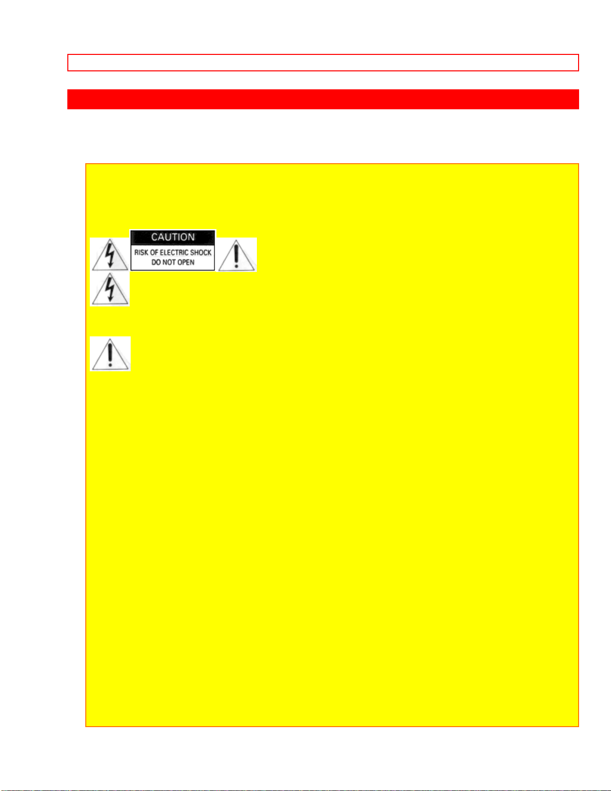
This symbol warns the user that uninsulated voltage within the unit may
have sufficient magnitude to cause electric shock. Therefore, it is dangerous
to make any kind of contact with any inside part of this unit.
This symbol alerts the user that important literature concerning the
operation and maintenance of this unit has been included. Therefore, it
should be read carefully in order to avoid any problems.
CAUTION:
TO PREVENT ELECTRIC SHOCK, MATCH WIDE BLADE OF PLUG TO W IDE SLOT ,
FULLY INSERT.
This digital apparatus does not exceed the Class B limits for radio emissions from digital
apparatus set out in the Radio interference regulations of the Canadian Department of
Communications.
Caution to the user: Changes or modifications not expressly approved by the manufacturer
could void the user's authority to operate the equipment.
CAUTION: Avoid operating your camcorder immediately after moving it from a cold area to
a warm humid area. Give the camcorder 2 to 3 hours to acclimate to the surroundings
before inserting a video cassette. When moved from a cold area to a warm humid area,
moisture may condense on the head drum inside the machine. This moisture could cause
the tape to stick to the headwheel and damage the headwheel or tape.
4
WARNINGS
PRECAUTIONS
Any problems that occur as a result of any of the following conditions will not be covered
by our warranty.
Be careful that no water, dust, or sand enters the camera/recorder.
When you are not using the camera/recorder, switch off the power and attach the lens
cap.
When you shoot at a scene which contains an extremely bright object such as the the
sun or a light source, a bright vertical bar may appear in the picture.
Your camera/recorder is functioning properly, but the solid-state pickup device (CCD)
usually causes this as an inherent characteristic. Try to avoid shooting an excessive
bright object directly.
Be sure not to leave it in a place where the temperature exceeds 120º F (49º C), or
the pickup device may be damaged.
Dangerous includes:
• Inside a car with the windows closed and in direct sunshine.
• Near heating appliances.
Do not leave the viewfinder lens facing sunlight for a prolonged period, or the
phosphorescent surface of the cathode ray tube may be damaged.
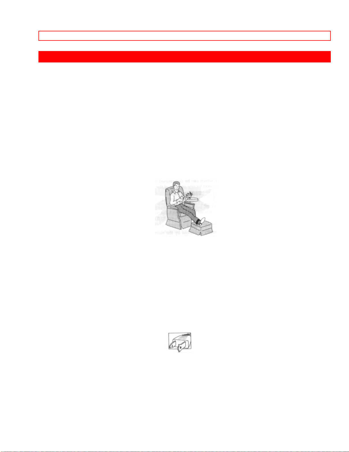
Thank you for choosing the video camera/recorder. For maximum pleasure and
convenience please read these simple instructions before operating your
camera/recorder.
WARNING: Many television programs and films are copyrighted. In certain circumstances,
copyright law may apply to private in-home video taping of copyrighted materials.
* This video camera/recorder with this marking incorporates high-quality
picture technology and is compatible with any video tape recorder bearing the
mark.
5
WARNINGS
FEATURES
• Digital zoom up to X 24 (only for VM-2600A)
• Solid-state camera pickup
• High Quality picture technology
• Auto focus power zoom Lens with macro feature
• Full record and playback capability with standard cassette
• High speed shutter
• Time lapse and one-shot recording
• Flying erase head
• Video dub
• Audio dub
• Time and date
• Titler
• Index signal
ACCESSORIES
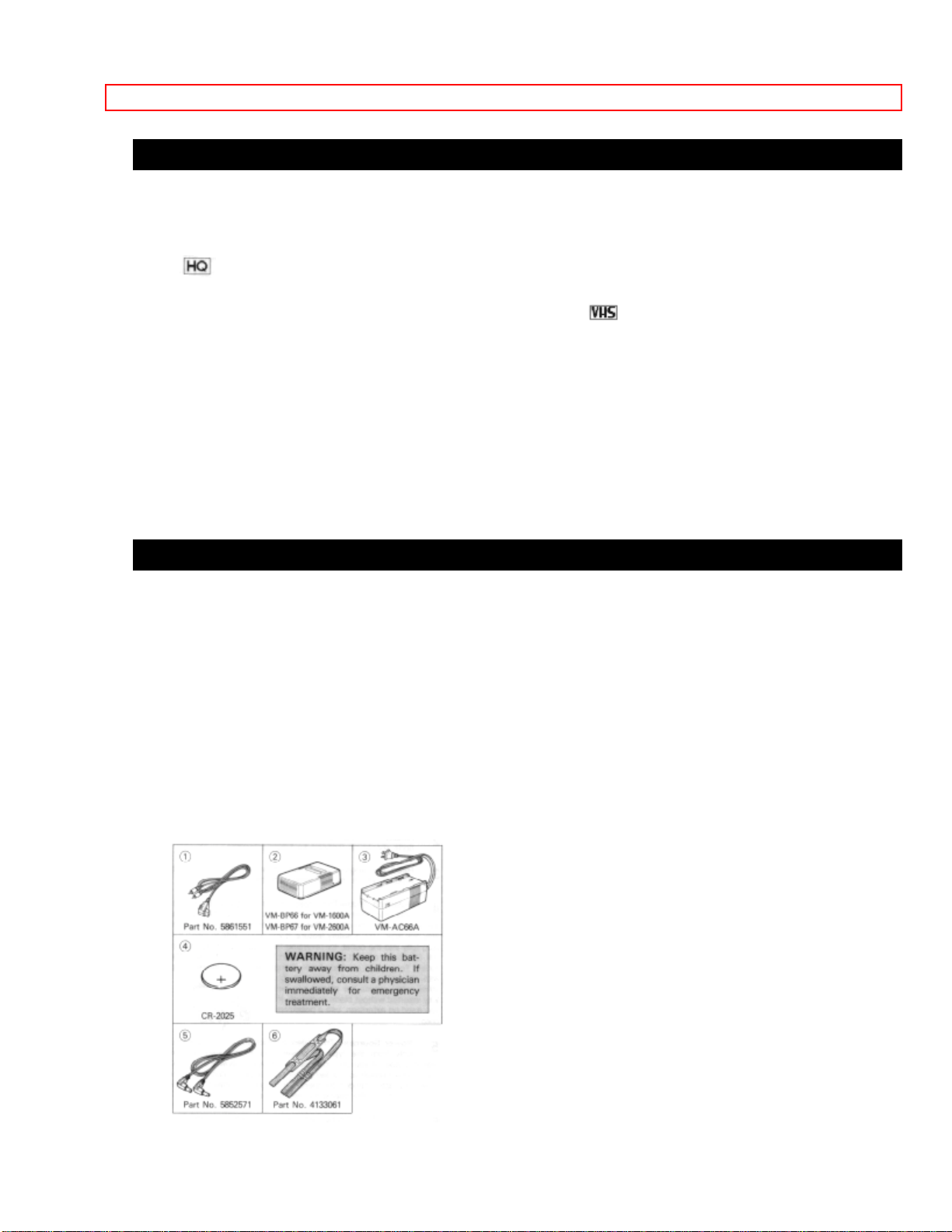
Check to make sure you have the following components and accessories (besides the
camera/recorder unit itself) before disposing of the packing material.
1. Video/Audio Output Cord
2. Lead-acid Rechargeable Battery
3. AC Adaptor/Charger
4. Battery for Date/Time
5. DC cord
6. Shoulder strap
6
IMPORTANT SAFEGUARDS
IMPORTANT SAFEGUARDS
In addition to the careful attention devoted to quality standards in the manufacture of
your video product, safety is a major factor in the design of every instrument. But,
safety is your responsibility too.
This page lists important information that will help to assure your enjoyment and proper
use of a Video Camera/Recorder and accessory equipment. Please read it carefully
before operating your video product and keep it in a handy place for future reference.
INSTALLATION
1 Read and Follow Instructions -- All the safety and operating instructions should be
read before the video product is operated. Follow all operating and use instructions.
2 Retain Instruction -- The safety and operating instructions should be retained for
future reference.
3 Heed Warnings -- Comply with all warnings on the video product and in the operating
instructions.
4 Polarized Plug -- This video product is equipped with a polarized alternating-current
line plug (a plug having one blade wider than the other). This plug will fit into the power
outlet only one way. This is a safety feature. If you are unable to insert the plug fully
into the outlet, try reversing the plug. If the plug should still fail to fit, contact your
electrician to replace your obsolete outlet. To prevent electric shock do not use this
polarized plug with an extension cord, receptacle or other outlet unless the blades can
be fully inserted without blade exposure. If you need an extension, use a polarized
cord.
5 Power Sources -- This video product should be operated only from the type of power
source indicated on the marking label. If you are not sure of the type of power supply to
your home, consult your video dealer or local power company. For video products
intended to operate from battery power, or other sources, refer to the operating
instructions.
6 Overloading -- Do not overload wall outlets and extension cords as this can result in a
risk of fire or electric shock. Overloaded AC outlets and extension cords are dang erous,
and so are frayed power cords, damaged or cracked wire insulation and broken plugs.
7
IMPORTANT SAFEGUARDS
They may result in shock or fire hazard. Periodically examine the cord and have it
replaced by your service technician if appearance indicates damage or deteriorated
insulation.
7 Power Cord Protection -- Power supply cords should be routed so that they are not
likely to be walked on or pinched by items placed upon or against them, paying
particular attention to cords at plugs, convenience receptacles, and the point where they
exit from the appliance.
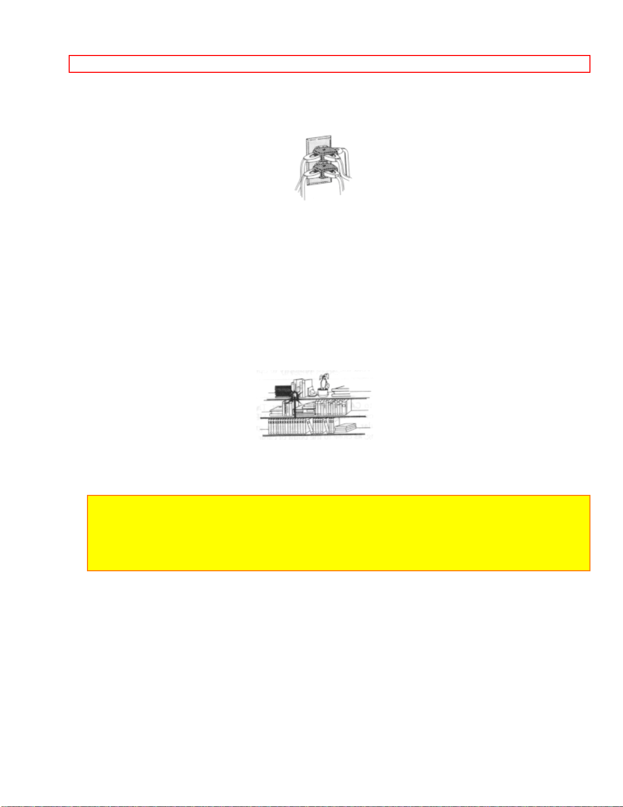
8 Ventilation -- Slots and openings in the cabinet are provided for ventilation to ensure
reliable operation of the video product and to protect it from overheating. These
openings must not be blocked or covered. The openings should never be blocked by
placing the video product on a bed, sofa, rug or other similar surface. This video
product should never be placed near or over a radiator or heat register. This video
product should not be placed in a built-in installation such as a bookcase or rack unless
proper ventilation is provided or the video product manufacturer's instructions have
been followed.
9 Attachments -- Do not use attachments unless recommended by the video product
manufacturer as they may cause hazards.
Caution: Maintain electrical safety. Power-line operated equipment or accessories
connected to this unit should bear the UL listing mark or CSA certification mark on the
accessory itself and should not have been modified so as to defeat the safety features.
This will help avoid any potential hazard from electric shock or fire. If in doubt, contact
qualified service personnel.
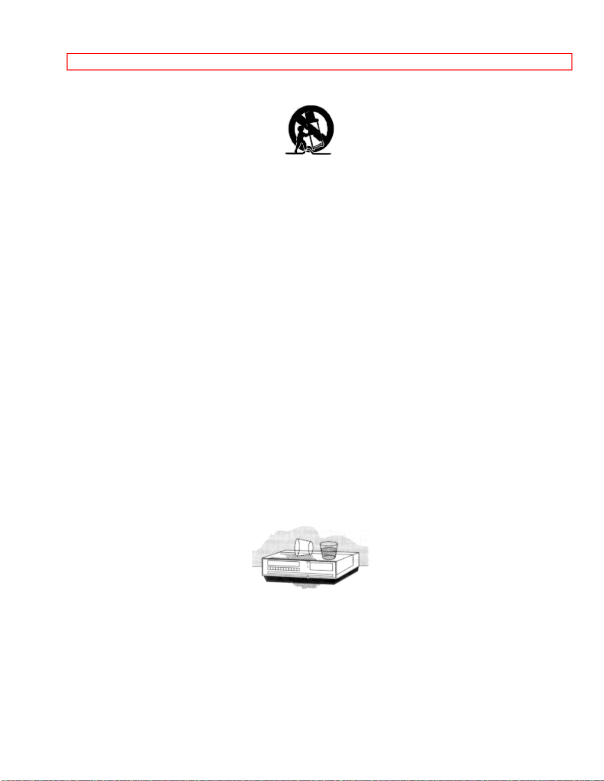
10 Water and Moisture -- Do not use this video product near water -- for example, near
a bath tub, wash bowl, kitchen sink, or laundry tub, in a wet basement, or near a
swimming pool, and the like.
11 Accessories -- Do not place this video product on an unstable card, stand, tripod,
bracket or table. The video product may fall, causing serious injury to a child or adult,
and serious damage to the appliance. Use only with a cart, stand, tripod, bracket or
table recommended by the manufacturer, or sold with the video product. Any mounting
of the product should follow the manufacturer's instructions, and should use a mounting
accessory recommended by the manufacturer.
11A An appliance and cart combination should be moved with care. Quick stops,
excessive force, and uneven surfaces may cause the appliance and cart combination to
8
IMPORTANT SAFEGUARDS
overturn.
12 Outdoor Antenna Grounding -- If an outside antenna or cable system is connected
to the video product, be sure the antenna or cable system is grounded so as to provide
some protection against voltage surges and built-up static charges. Section 810 of the
National Electrical Code, ANSI/NFPA No. 70, provides information with respect to
proper grounding of the mast and supporting structure, grounding of the lead-in wire to
an antenna discharge unit, size of grounding conductors, location of antenna-discharge
unit, connection to grounding electrodes, and requirements for the grounding electrode.
See example below:
EXAMPLE OF ANTENNA GROUNDING
13 Power Lines -- An outside antenna system should not be located in the vicinity of
overhead power lines or other electric light or power circuits, or where it can fall into
such power lines or circuits. When installing an outside antenna system, extreme care
should be taken to keep from touching or approaching such power lines or circuits as
contact with them might be fatal. Installing an outdoor antenna can be hazardous and
should be left to a professional antenna installer.
USE
14 Cleaning -- Unplug this video product from the wall outlet before cleaning. Do not
use liquid cleaners or aerosol cleaners. Use a damp cloth for cleaning.
15 Object and Liquid Entry -- Never push objects of any kind into this video product
through openings as they may touch dangerous voltage points or short-out parts that
could result in a fire or electric shock. Never spill liquid of any kind on the video
product.
16 Lightning -- For added protection for this video product during a lightning storm, or
when it its left unattended and unused for long periods of time, unplug it from the wall
outlet and disconnect the antenna or cable-system. This will prevent damage to the
video product due to lightning and power-line surges.
9

IMPORTANT SAFEGUARDS
10

IMPORTANT SAFEGUARDS
17 Servicing -- Do not attempt to service this video product yourself as opening or
removing covers may expose you to dangerous voltage or other hazards. Refer all
servicing to qualified service personnel.
18 Conditions Requiring Service -- Unplug this video product from the wall outlet and
refer servicing to qualified service personnel under the following conditions.
a. When the power-supply cord or plug is damaged
b. If liquid has been spilled or objects have fallen into the video product.
c. If the video product has been exposed to rain or water.
d. If the video product does not operate normally by following the operating instructions.
Adjust only those controls that are covered by the operating instructions. Improper
adjustment of o t her controls may result in damage and will often require extensive work
by a qualified technician to restore the video product to its normal operation.
e. If the video product has been dropped or the cabinet has been damaged.
f. When the video product exhibits a distinct change in performance -- this indicates a
need for service.
19 Replacement Parts -- When replacement parts are required, have the service
technician verify that the replacements he uses have the same safety characteristics as
the original parts. Use of replacements specified by the video product manufacturer can
prevent fire, electric shock or other hazards
20 Safety Check -- Upon completion of any service or repairs to this video product, ask
the service technician to perform safety checks recommended by the manufacturer to
determine that the video product is in safe operating condition.
21 Heat -- The product should be situated away from heat sources such as radiators,
heat registers, stoves, or other products (including amplifiers) that produce heat.
SERVICE
11

IMPORTANT SAFETY INSTRUCTIONS FOR AC ADAPTER/CHARGER
IMPORTANT SAFETY INSTRUCTIONS FOR AC ADAPTER/CHARGER
1. Save these instructions - This page contains important safety and operating
instructions for AC Adaptor/Charger Model VM-AC66.
2. Before using AC Adaptor/Charger, read all instructions and cautionary markings on
(1) AC Adapter/Charger, (2) battery and (3) product using battery.
3. Also read all instructions on pages 4 and 5.
4. Caution--To reduce the risk of injury, charge only rechargeable battery, VM-BP64/BP65/
BP66/BP67. Other types of batteries may burst causing personal injury and damage.
5. Do not expose charger to rain or snow.
6. Use of an attachment not recommended or sold by the battery charger manufacturer
may result in a risk of fire, electric shock, or injury to persons.
7. To reduce the risk of damage to electric plug and cord, pull by plug rather than cord
when disconnecting charger.
8. Make sure cord is located so that it will not be stepped on, tripped over, or otherwise
subjected to damage or stress.
9. Do not operate charger with damaged cord or plug - replace them immediately.
10. An extension cord should not be used unless absolutely necessary.
Use of improper extension cord could result in a risk of fire and electric shock. If
extension cord must be used, make sure:
A. That the pins on plug of extension cord are the same number, size, and shape as
those of plug on charger.
B. That extension cord is properly wired and in good electrical condition; and
C. That wire size should be met below:
Minimum AWG size Length of extension cord (feet)
18 Equal to or less than 100
16 Equal to or less than 150
11. Do not operate charger if it has received a sharp blow, been dropped, or otherwise
damaged in any way; take it to a qualified serviceman.
12. Do not disassemble charger; take it to a qualified serviceman when service or repair
is required. Incorrect reassembly may result in a risk of electric shock or fire.
13. To reduce the risk of electric shock, unplug charger from outlet before attempting
any maintenance or cleaning.
"Note to CATV system installer: This reminder is provided to call the CATV system
installer's
attention to Article 820-40 of the NEC that provides guidelines for proper grounding and, in
particular, specifies that the cable ground shall be connected to the grounding system of
the building,
as close to the point of cable entry as practical".
12
ELECTRONIC VIEWFINDER (EVF)
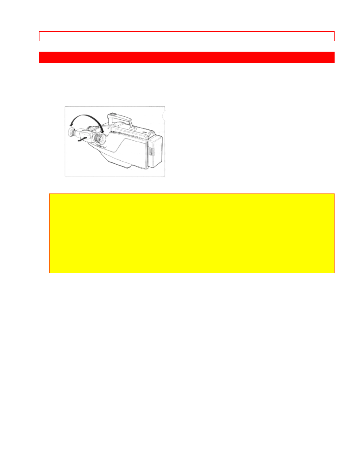
ELECTRONIC VIEWFINDER (EVF)
You can adjust the position and angle of the viewfinder so you can see through it easily
with your left eye as well as your right eye.
NOTE: Put the viewfinder back to original position when storing the camera/recorder into
the carrying case or carrying the camera/recorder.
CAUTIONS:
• Do no force the viewfinder to rotate completely around. This will damage the viewfinder
and/or camera/recorder.
• When pulling the viewfinder out or returning it to its original position, hold the viewfinder
by the swivel section. Do not hold the diopter control side.
13
LOADING BATTERY FOR DATE/TIME
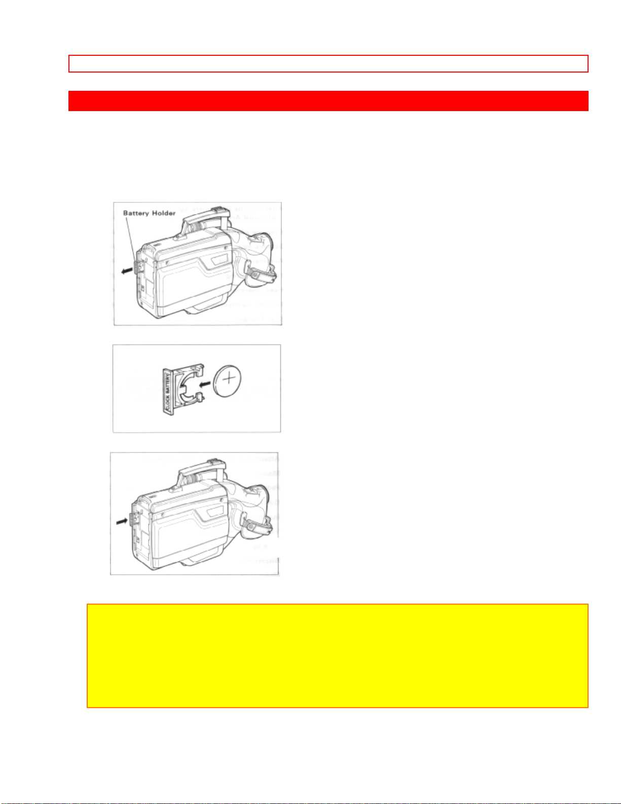
LOADING BATTERY FOR DATE/TIME
You may want to install the date/time battery (provided) immediately to prevent
misplacing it.
1. Pull the battery holder with coint etc.
2. Insert the date/time battery with the "+" terminal facing out.
3. Fully insert the battery holder into the camera/recorder.
NOTES:
• When replacing the batteries, use 3V micro lithium cell such as Maxell CR2025 or
equivalent.
• Instructions for setting the time and date are on page 22. You can do that later if desired
after you're more familiar with your camera/recorder.
• Dispose of battery safely and in accordance with local laws.
• Do not dispose of in fire.
14

LOADING BATTERY FOR DATE/TIME
WARNING:
Keep this battery away from children. If swallowed, consult a physician immediately for
emergency treatment.
15
POWER SOURCES
POWER SOURCES
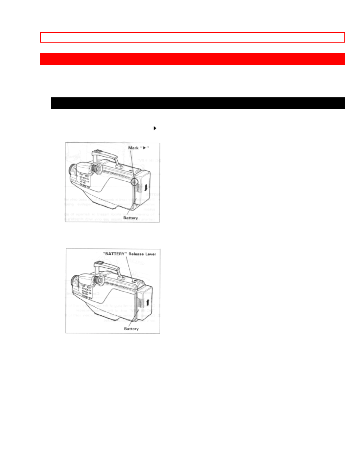
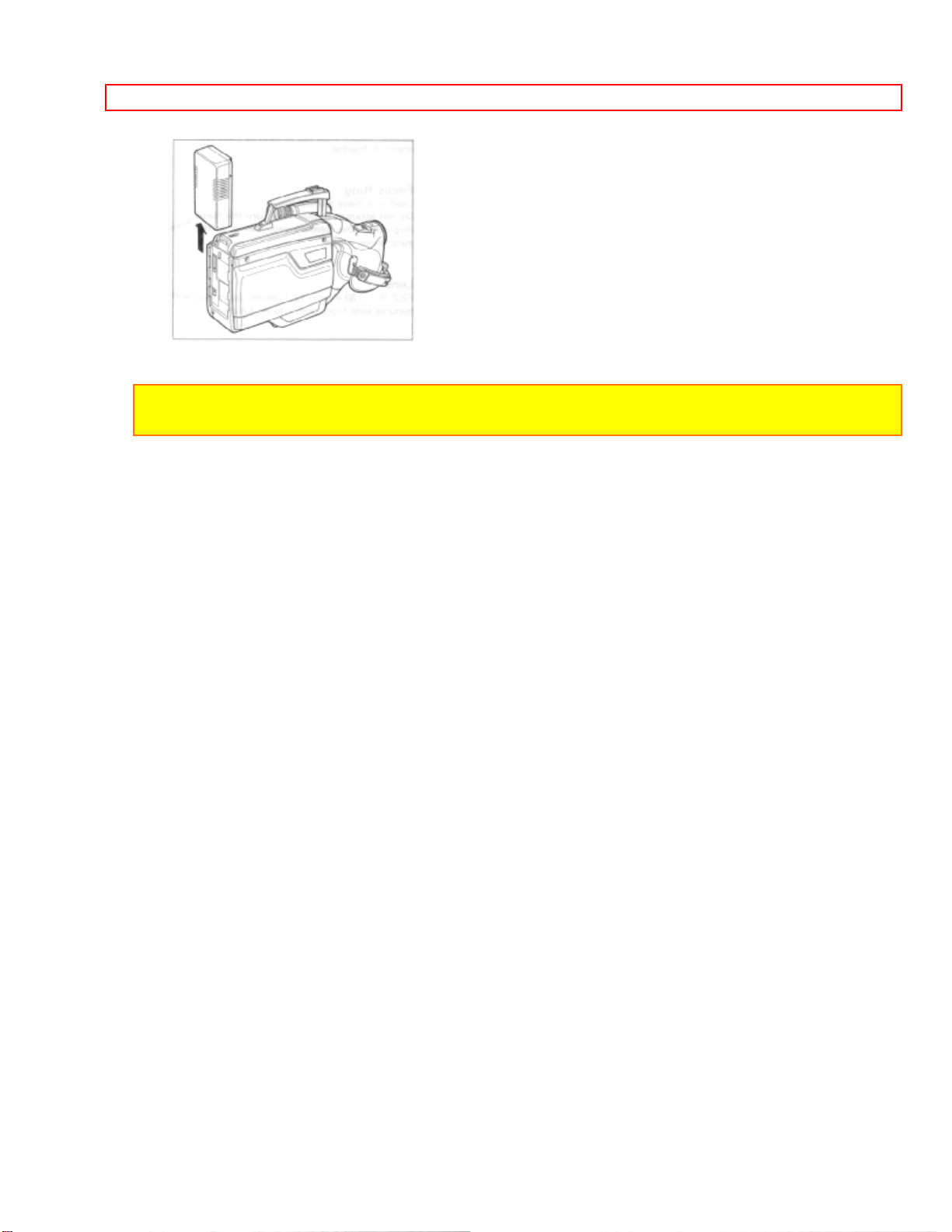
WHEN USING WITH THE BATTERY (Provided)
• To attach, align the mark " " of the battery with that of the camera/recorder so that the
battery fits into the groves, and slide the battery downward, as illustrated.
• To remove the battery:
Push and hold "BATTERY" release lever, then slide the battery to the upside and
remove.
16
POWER SOURCES
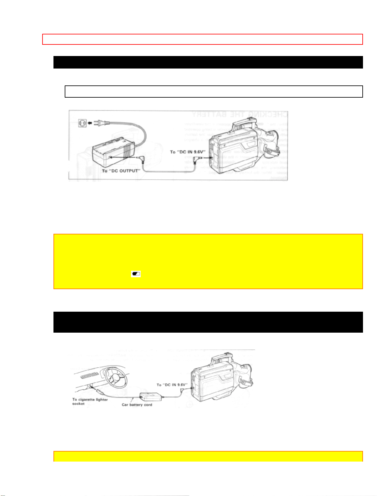
WHEN USING WITH THE AC ADAPTER/CHARGER (Provided)
See the rating label of the AC adaptor/charger.
1. Plug the AC adaptor/charger power cord into AC electrical outlet.
2. Connect one end of the DC cord (provided) to the "DC IN 9.6V" of the
camera/recorder.
Connect the other end of the DC cord to the "DC OUTPUT" of the AC adaptor/charger.
NOTES:
• The AC adaptor/charger cannot charge the battery and operate the camera/recorder at
the same time.
• When using the AC adaptor/charger to power the camera/recorder, the battery level
indicator may display " ". This indicator is used for battery operation and has no meaning
when using the AC adaptor/charger to power the camera/recorder.
WHEN USING WITH THE CAR BATTERY (By using optional car battery cord Hitachi
VM-CC70A)
1. Connect the small plug of the car battery cord to the "DC IN 9.6V" jack of the
camera/recorder.
2. Connect the other end of the car battery cord to the car's cigarette lighter socket.
NOTES:
17

POWER SOURCES
• The car battery cord is designed to be used only with automobiles having a 12-volt
negative ground system.
• To prevent fire or shock hazard or damage to your camera/recorder, please use with
Hitachi's car battery cord model VM-CC70A.
18
CHECKING THE BATTERY
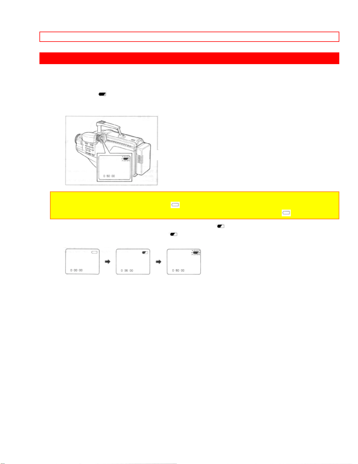
CHECKING THE BATTERY
When the " " indication appears in the viewfinder and flashes while the
camera/recorder is being operated with a battery (provided), it indicates that the battery
charge is low. Charge it or replace it with a charged battery.
NOTE: Whenever the linear time counter or time remaining display is present in the
viewfinder, the battery level indicator " " is displayed in the viewfinder indicating the
condition of camera/recording battery. When the battery is fully charged, " " is displayed.
After several minutes, the symbol will change to " ". When the battery is very near
empty, the symbol will change to " " and start blinking. You should find an alternative
power source or recharge the battery before continuing to use your camera/recorder.
19
CHARGING A BATTERY
CHARGING A BATTERY
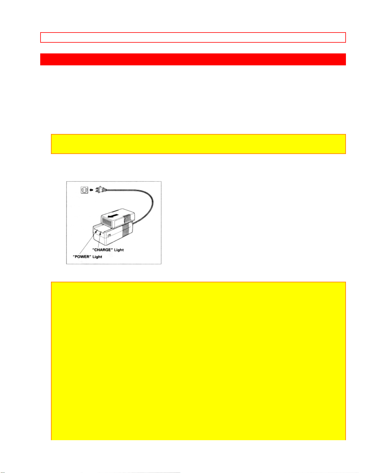
1. Plug the AC adaptor/charger power cord into AC electrical outlet.
2. Attach the battery to the AC adaptor/charger. Align the reference arrow on the battery
with that of AC adaptor/charger and push the battery flush with the AC adaptor/charger
and slide it in the direction of arrow.
NOTE: You must remove the DC cord from the AC adaptor/charger to charge the battery. If
the DC cord is connected, "CHARGE" light will not light.
3. The "CHARGE" light will be lit while the battery is accepting a charge, and will go out
when the battery is fully charged.
NOTES:
1. The time required for charging the battery is approx. two hours for VM-BP66 and three
hours for VM-BP67.
2. When fully charged, the battery should supply approx. 90 ~ 120 minutes of operating
time for VM-BP67 (45 ~ 60 minutes for VM-BP66) (depending on how much you use zoom
and pause).
3. Charge the battery after use and store it at normal room temperature.
4. Recharge the battery at least once every six months. The battery is a lead-acid battery.
This battery tends to discharge if not used for an extended period of time. If the battery is
stored for an extended length of time without being recharged, you may not be able to
recharge it.
5. A battery charged after being stored for a long period may not supply power for the
specified time. Additional rechargings will help restore the battery's operation time.
6. The battery should be charged at a temperature of 50ºF - 86ºF (10ºC - 30ºC) to prevent
damage.
7. Do not operate the battery at temperatures below 14ºF (-10ºC) or above 95ºF (35ºC).
The battery may be damaged if operated at temperatures above 122ºF (50ºC). Operation
time will decrease at extremely low temperatures.
8. After repeated chargings and use, the operation time will gradually decrease. When
20

CHARGING A BATTERY
operation time becomes too short to be useful, it is time to replace the battery.
9. If "CHARGE" and "POWER" lights on the AC adaptor/charger start flashing, remove the
battery and then reattach it. If after several attempts both lights continue to flash, this
means your battery cannot take a charge and must be replaced with a new one.
The "CHARGE" light will not light if a hot battery is attached to the AC adaptor/charger.
Attaching an extremely hot battery to the adaptor/charger is not recommended; it should be
allowed to cool down before being attached.
10. Do not short the battery's terminal.
11. Do not attempt to disassemble or modify the battery. There are no user serviceable
parts inside.
12. Throwing the battery into a fire or exposing the battery to excessive heat - over 149ºF
(65ºC) could be hazardous.
13. Be sure to set the "POWER" switch to the "OFF" position before removing the battery.
ATTENTION:
The product that you have purchased contains a rechargeable battery. The battery is
recyclable. At the end of its useful life under various state and local laws, it may be illegal to
dispose of this battery into the municipal waste stream. Check with your local solid waste
officials for details in your area for recycling options or proper disposal.
21
MAKING A SAMPLE RECORDING
MAKING A SAMPLE RECORDING
1. Connect the POWER SOURCE. (See pages 9 and 10.)
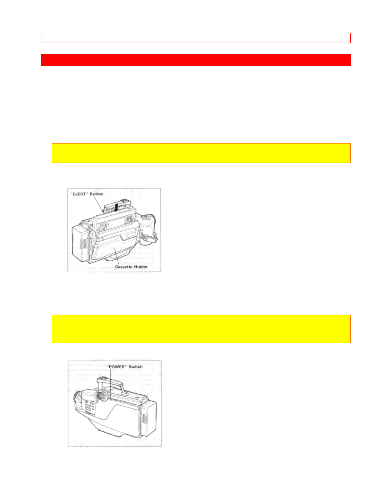
2. Press "EJECT" button and insert the cassette so the transparent window is toward
you and the arrow toward the cassette holder. Slide the cassette into cassette holder as
far as it will go.
NOTE: Push in the center of the cassette all the way until it is latched by the cassette
holder.
3. Press the cassette holder. The holder will latch in the operating position.
4. Press and hold the small button on "POWER" switch, and then slide it to the "CAM"
position. The "POWER" indicator will light and the camera/recorder will enter
record/pause mode automatically.
NOTE: If the erase prevention tab on the cassette is removed, the "TAPE" indication in the
viewfinder flasher for several seconds and the camera/recorder will not enter record/pause
mode.
22

MAKING A SAMPLE RECORDING
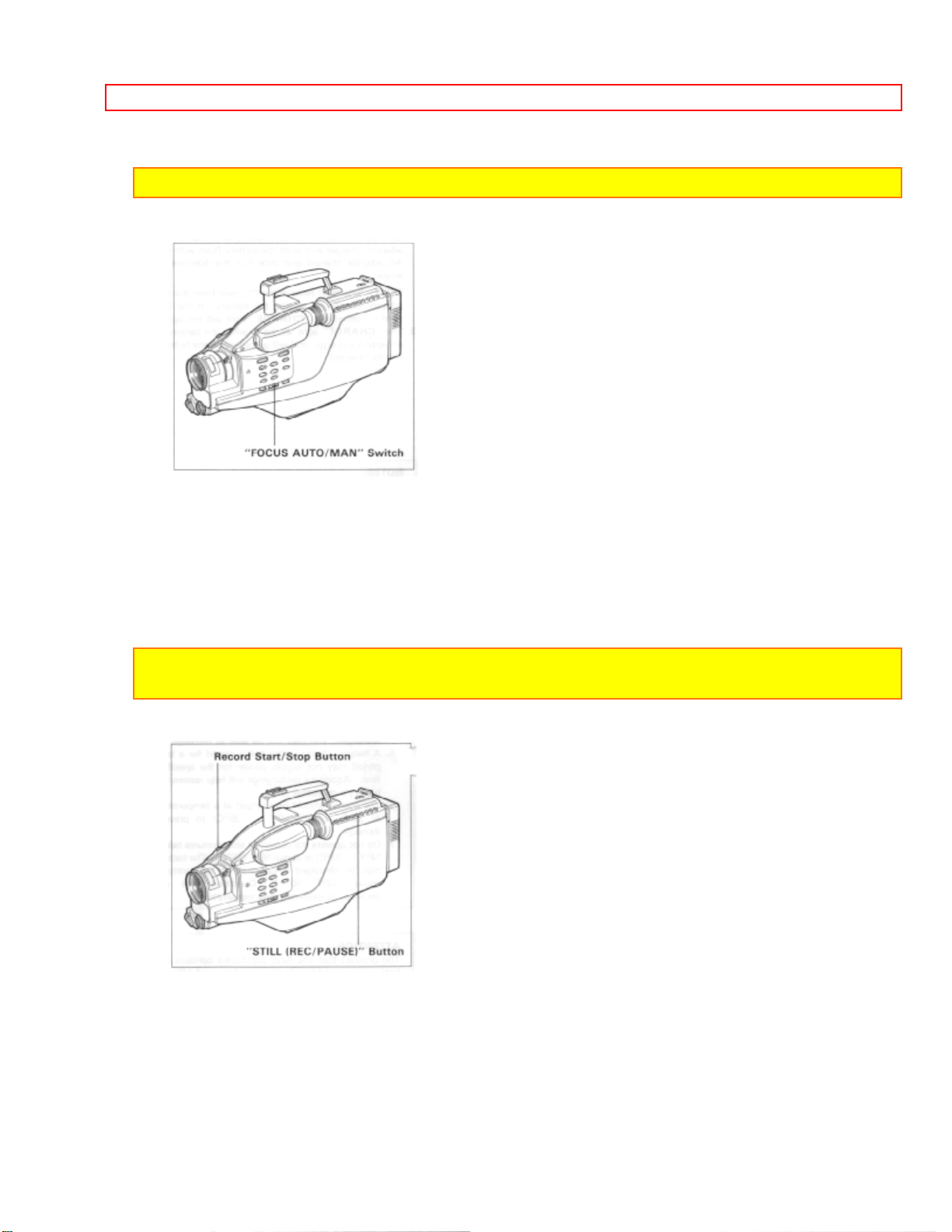
5. Set "FOCUS AUTO/MAN" switch to "AUTO".
23
MAKING A SAMPLE RECORDING
NOTE: See page 43 for "EYEPIECE ADJUSTMENT".
6. Now, press record star/stop or "STILL (REC/PAUSE)" button to start shooting the
picture. The "REC" indication appears in the viewfinder and you are now recording the
picture you see through the viewfinder.
7. Press record start/stop or "STILL (REC/PAUSE)" button to stop recording. Press the
button again to resume recording. The "PAUSE" indication will appear in the viewfinder
instead of "REC" while the camera/recorder is in the record/pause (stand-by) mode.
NOTES: The "TAPE END" indication starts flashing in the viewfinder when there is about
five minutes recording time left on the cassette.
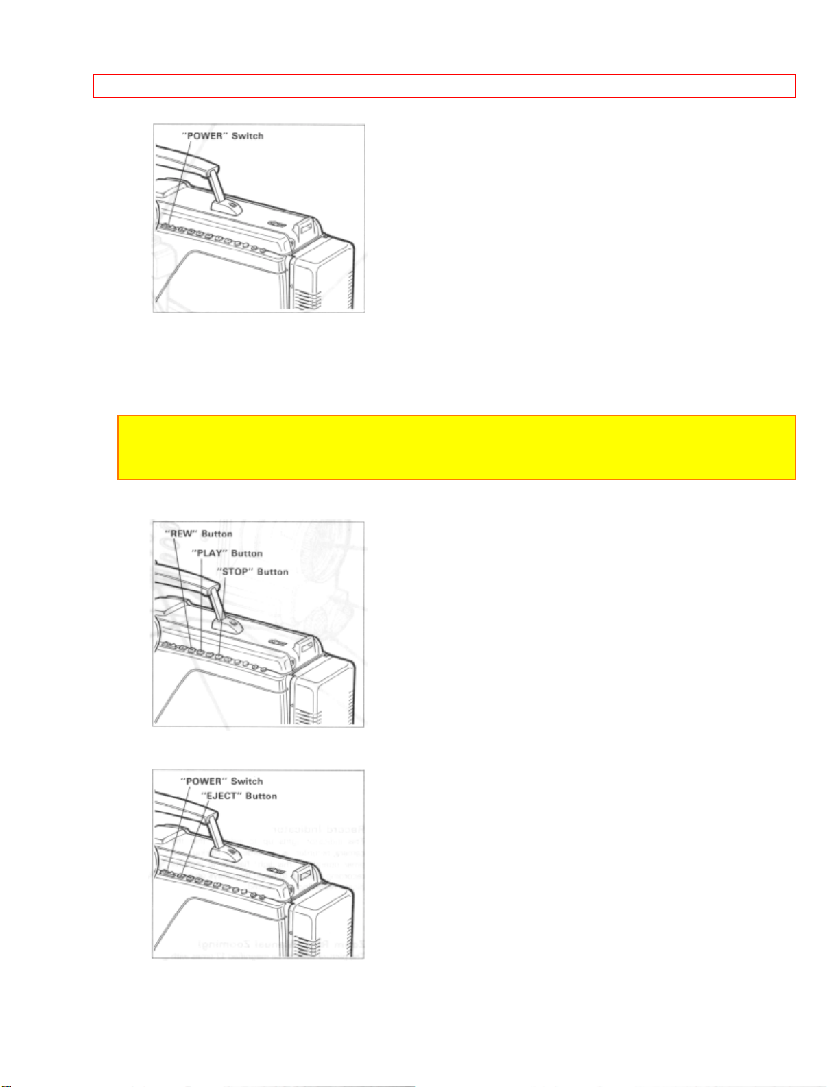
8. After recording, press and hold the small button on the "POWER" switch, and then
slide it to "VIDEO". The camera/recorder will now be in the stop mode.
24
MAKING A SAMPLE RECORDING
9. Press "REW" button. The tape will be rewound to the beginning
10. Press "PLAY" button. The picture you just recorded will be seen through the
viewfinder.
NOTE: If you connect the camera/recorder to your TV, you can see the picture played back
on your TV. Refer to "VIEWING THE PICTURE PLAYED BACK ON YOUR TV" on page
38.
11. After playing, press "STOP" button.
12. Slide the "POWER" switch to "OFF" position to turn off the camera/recorder. Press
"EJECT" button to remove the cassette.
13. Always remove the power source from the camera/recorder after use.
25
MAKING A SAMPLE RECORDING
NOTE: If you have a cassette tape that has already been partially recorded on and you
want to record the remaining blank section, see "QUICK EDIT" on page 27.
26

IDENTIFICATION AND OPERATION OF CONTROLS
IDENTIFICATION AND OPERATION OF CONTROLS
Diagram of camera
Accessory Shoe
Used to attach the DC camera light (optional).
Record Indicator
This indicator lights up to indicate that the camera/recorder is recording. During self
timer operation, this light flashes to indicate recording is about to begin then stays on to
indicate recording has started.
Zoom Ring (Manual Zooming)
The picture size can be magnified 12 times with the use of the zoom feature. Just rotate
the zoom ring for a close up (T) or wide angle (W) picture. Macro close-up, as close as
1 cm from object is feasible.
Focus Ring
Used to acheive manual focus.
Do not attempt to manually turn the focus ring when the camera/recorder is in the auto
focus mode.
Lens
F2.2 (6.7 ~ 80.4 mm) 12:1 power zoom lens features auto focus and auto iris functions.
Auto Focus Window
To automatically focus the camera lens, this window transmits and receives infrared
light which is reflected off the object. Make sure you don't obstruct this window when
recording.
Microphone
Sensitive to source coming from the direction in which the camera is pointed.
"PUSH/AUTO" Focus Button
Auto focusing can be also performed during manual focus mode by pushing this button.
"FOCUS AUTO/MAN" Switch
Set this switch to the "AUTO" position for automatic focusing, and to the "MAN" position
for focusing with the focus ring.
"BATTERY" Release Lever
27

IDENTIFICATION AND OPERATION OF CONTROLS
Releases the battery attached to the video camera/recorder.
"LOW LIGHT" Button
Press this button when shooting in a dark place such as outdoors at night. You can
record the subject as a bright picture.
NOTE: This switch has no effect in a bright place.
"DISPLAY" Button
Pressing this button once cause a 5 digit linear timer counter and battery indicator to
appear in the camera/recorder's viewfinder. Pressing the button again will cause battery
indicator and the amount of time remaining on the cassette in the camera/recorder.
Press a 3 time to delete all displays.
"SHUTTER" Button
Used to control the shutter speed during recording and/or record/pause (stand-by)
mode. (See "VARIABLE SHUTTER SPEED" on page 28.)
Diagram of Camera
Diopter Control
To use the electronic viewfinder without eyeglasses on, turn this control knob for your
optimum focus adjustment.
Cover for DC camera Light Termina l
When the DC camera light is attached to the accessory shoe, this cover slides and
power can be supplied to the DC camera light.
Caution: To help avoid any potential hazard from electric shock, do not open this cover
when the DC camera light is not attached and the camera/recorder is turned on.
Electronic Viewfinder (EVF)
Displays what the camera/recorder lens sees. The electronic viewfinder also functions
as a convenient black-and-white monitor during playback of recorded material.
"BACK LIGHT" Button
When the subject is lit from behind, press and hold this button to compensate for the
back-lighting.
"REVIEW" Button
28

IDENTIFICATION AND OPERATION OF CONTROLS
Used to review the last few seconds of the recorded seg ment in the r ecor d/pause mode.
"TITLE" Button
Press this button to create and record personalized titles on your videos with the
camera/recorder's built-in titler.
(See "TITLE RECORDING" on page 34.)
"RESET/T-160/T-180" Button
When the linear time counter is displayed in the viewfinder, pressing this button resets
the counter to "0:00:00".
When the time-remaining read-out is displayed, pressing this button changes the
display for extended length T-160 or T-180 tape. "T-160" or "T-180" will appear in the
viewfinder.
"FADE" Button
During recording you can add a professional touch to your recordings by fading in and
out of scenes.
NOTE: When you use "FADE" button to fade in and out, the sound will also fade in and out
with the picture.
"SELF TIMER/TIME LAPSE" Button
This button allows time lapse, one shot and self timer recording. See pages 30 and 31.
"DATE / TIME" Button
Press this button to display the date and time in the viewfinder.
Whenever the date and time appear in the viewfinder, they will be recorded on the tape.
29

IDENTIFICATION AND OPERATION OF CONTROLS
Diagram of buttons
"PLAY" Button
Used for playback of tape recorded in the SP mode.
NOTE: When the camera/recorder is in the record/pause (stand-by) mode, pressing and
holding this button will play the tape at normal speed.
"REW" Button
Press this button during stop or fast forward mode, and fast-rewinding starts. "REWIND"
appears in the viewfinder whenever the tape counter or ti me r emai ning i s pr esent. Pr ess
the button during playback of tape, and the tape is played back in the rewind direction
approximately 3 times faster than the normal speed to confirm the recorded contents.
Press "PLAY" button to return to normal playback mode or press "STOP/EJECT" button
to stop tape movement.
NOTE: You can also visually scan backward when the camera/recorder is in record/pause
(stand-by) mode by pressing and holding this button.
"EJECT" Button
Operates with "POWER" either on or off, if a power source is connected to the
camera/recorder.
"POWER" Light
"POWER" Switch
This switch changes the camera/recorder to the record mode or to the playback mode.
Press and hold the small button on this switch, and then slide it to "CAM", "OFF" or
"VIDEO".
"EAR" phone Jack
Sound being recorded by the microphone or played back may be monitored by
attaching earphone (Not supplied) to this jack.
"MIC" Jack
Connect an external microphone (Not supplied) here to record sound from the external
microphone.
NOTE: Connecting an external microphone automatically switches off the built-in
30

IDENTIFICATION AND OPERATION OF CONTROLS
microphone.
"MIC WIND/NORM" Switch
This switch is used to reduce noise that occurs due to wind. Place the switch in the
NORMAL position for normal use.
"F.FWD" Button
Press this button during stop or rewind mode, and fast-forwarding starts. "FAST FWD"
appears in the viewfinder whenever the tape counter or time remaining is present.
Press the button during playback of tape, and the tape is played back in the forward
direction approximately 3 times faster than the normal speed to confirm the recorded
content.
Press "PLAY" button to return to normal playback mode or press "STOP" button to stop
tape movement.
NOTE: You can also visually scan forward when the camera/recorder is in record/pause
(stand-by) mode by pressing and holding this button.
"STOP" Button
The "STOP" button is used to stop playback, rewind, and fast forward operations. The
"STOP" button has no effect during record operation.
"AUDIO DUB" Button
This button is used to record new audio in place of existing audio without erasing the
video. See page 36.
"VIDEO DUB" Button
This button is used to record new video in place of existing video without erasing the
audio. See page 37.
"TRACKING" Button
Used when playing a tape recorded on another VCR. Adjust for best picture. Ejecting
the cassette returns the tracking to the normal position.
"STILL (REC/PAUSE)" Button
When this button is pressed during recording, the tape stops and the camera/recorder
enters the record/pause (stand-by) mode. When this button is pressed again, the tape
begins recording. This button may be also used to display a still picture durin g pla yback
mode.
(REW, PLAY, F.FWD, and STOP/EJECT)
31

IDENTIFICATION AND OPERATION OF CONTROLS
• These buttons are used for title making buttons when the "TITLE" button is pressed.
(See "TITLE RECORDING" on page 34.)
• These buttons may be also used to set the date and time during pause (stand-by)
mode. (See "DATE/TIME SETTING" on page 22.)
Diagram of Camera
Cassette Holder
Press "EJECT" button to open the cassette holder. Be aware of the cassette direction
when inserting.
NOTE: Power source must be connected to open the cassette holder.
Clock Battery Compartment
Pull the battery holder and install the clock battery (provided).
"DC IN 9.6V" Jack
When using the AC adaptor/charger (provided) or the car battery cord (optional),
connect this jack and the "DC OUTPUT" of the AC adapter/charger or the car's cigarette
lighter socket.
"MIC MIX (ON/OFF)" Switch
This switch lets you add additional comments (or music) to a tape while you are copying
a tape from your camera/recorder onto another VCR.
"AV OUT" Jack
Connec the video/audio output cord (provided) to this jack and to the audio and video
inputs of your TV/monitor receiver. You may also connect the RF converter unit to this
jack and your TV receiver.
"AV IN" Jack
Use this connector jack when you want to send signals from another device into your
camera/recorder for recording.
"Record Start/Stop" Button
This button is used to control the camera/recorder. When the "POWER" switch is set to
the "CAM" position, pressing this button starts the tape to begin recording. "REC"
appears in the viewfinder.
When this button is pressed again, "PAUSE" appears instead of "REC" and the tape
stops and the camera/recorder enters the record/pause (stand-by) mode.
Power Zoom Switch
32

IDENTIFICATION AND OPERATION OF CONTROLS
This switch performs zooming electrically.
"W": Picture becomes wider gradually.
"T": Picture becomes telescopic gradually.
Lens Cap Tab
Place the lens cap on this tab when you are ready to record a scene. The tab also
prevents the lens cap from swinging around on its cord.
Hand Strap
Adjust to best fit your hand.
33

DATE/TIME SETTING
DATE/TIME SETTING
The date and time can be recorded on your tape to act as a handy reference when
viewing them at a later time. Since camera/recorder has a dual timer feature, if you go
abroad to a country with a time difference, you can also record the time at the site
together.
Use the following procedure to set up this display for the current date and time.
To set the first clock
1. Load the camera/recorder's date/time battery as described on page 8.
2. Press and hold the small button on "POWER" switch, and then slide it to "CAM"
position.
3. Press "DATE/TIME" button.
Date and time appear in the viewfinder and "1" flashes.
4. Press "F.FWD" button to select correct month. Hold button down to advance rapidly.
If you go past the month you want to set, press "REW" button. When the correct month
appears, press "STOP" button.
5. Press "F.FWD" button to select correct date. Hold button down to advance rapidly. If
you go past the date you want to set, press "REW" button. When the correct date
appears, press "STOP" button.
6. Press "F.FWD" or "REW" button to select year, and then press "STOP" button.
7. Press "F.FWD" or "REW" button as many times as may be required to select the
correct hour, and then press "STOP" button.
8. Repeat step 7 to select minute and AM/PM.
34

DATE/TIME SETTING
9. After setting AM or PM, press "STOP" button to change the display and start the
internal clock.
10. Press "DATE/TIME" button after setting the clock. The display will change as follows
each time the button is pressed.
35

DATE/TIME SETTING
NOTE:
• See the next page for setting the second clock.
• The date/time graphics will be recorded whenever they appear in the viewfinder.
To correct date/time information after starting the date/time
1. Press and hold "DATE/TIME" button, and then press "STOP" button. The month
starts flashing.
2. Correct the incorrect digit by using "F.FWD", "REW" and "STOP" buttons.
To correct date/time information during programming
1. Press "STOP" button repeatedly until the flashing cursor will be removed from the
viewfinder.
2. Follow steps 1 and 2 of "To correct date/time information after starting the date/time".
To set the second clock
(The first clock operates even if you do not set the second clock.)
Before setting
Set the first clock first. The second clock cannot be set unless the first clock has been
set.
Example
When you go abroad where there is a time difference of minus 5 hours:
1. Press the "DATE/TIME" button to display the second clock.
2. Select the month, day, year following the same steps as "To set the first clock".
3. Select the correct hour, and then press "STOP" button.
36

DATE/TIME SETTING
4. Select AM/PM.
NOTES:
• The minutes of the second clock can not be set. they are the same as those of the first
clock.
• The first clock operates even while the second clock is being set.
5. After setting AM or PM, press "STOP" button to erase the flashing cursor.
NOTES:
• When the date or time of the first clock is flashing, you cannot delete the display.
• When you correct the minutes of the first clock, the minutes of the second clock are
corrected automatically.
37

AUTO FOCUS
AUTO FOCUS
When the "FOCUS AUTO/MAN" switch is set to "AUTO" position, ordinary objects are
automatically in optimum focus.
OBJECTS HARD TO AUTO FOCUS
1. Objects is not in the center.
2. Object in far and near positions at the same time.
3. Object with continuous variation from far to near positions.
4. Object behind glass.
38

AUTO FOCUS
MANUAL FOCUS
5. Black object or water which does not reflect infrared light.
6. Object always moving such as a crowd.
7. Object in the snow or fog.
8. Objects more than 50 feet away.
1. Set "FOCUS AUTO/MAN" switch to "MAN" position.
2. Zoom in on the object by pressing the power zoom switch on the "T" side.
NOTE: See below for "POWER ZOOM".
3. Focus on the object by turning the focus ring.
NOTE: If focusing is performed without zooming up first, the picture may become out of
focus when the zoom-in is done during actual picture taking.
4. Then, zoom out from the object as desired. The object will remain in focus.
39

AUTO FOCUS
40

EXPOSURE CORRECTION
EXPOSURE CORRECTION
This camera/recorder is provided with an auto iris mechanism which automatically
adjusts the lens aperature in accordance with the available light. When the object is
dark, the iris opens automatically, and it closes when the object is bright. When the
power is switched off, the iris is automatically set to the fully closed position.
When the background is brightly lit and the subject appears too dark, press and hold
down "BACKLIGHT" button during recording. While "BACKLIGHT" button is depressed,
you can correct the back light.
41

POWER ZOOM
POWER ZOOM
• Press power zoom switch on the "W" side, and the picture gradually widens.
• Press power zoom switch on the "T" side, and the picture gradually becomes
telescopic.
42

DIGITAL ZOOM (Only form VM-2600A)
DIGITAL ZOOM (Only form VM-2600A)
This feature allows you to increase the magnification of the image at the center of the
screen up to 2 times greater than the extreme telephoto position.
Press and hold "T" side of the power zoom switch. The digital zoom functions from the
extremely telephoto position of X12.
The digital zoom enlarges the image from X12 to X24. You can control the digital
enlargement ratio by pressing the "T" or "W" side of the power zoom switch. When the
zoom ratio falls below X12, the normal zooming function is restored.
NOTE: If you select a zoom ratio over X12 , it is displayed in the viewfinder. At X16, for
example, "X16" is displayed.
43

ATTACHING THE TELEPHOTO OR WIDE ANGLE LENS
ATTACHING THE TELEPHOTO OR WIDE ANGLE LENS
1. To remove the lens hood, turn the focus ring to the 0.7 meter position, then turn it
counterclockwise as shown in the figure.
NOTE: To attach the lens hood, align the convex section of the lens hood and the concave
section of the lens, then turn the focus ring to the infinity ( ) mark and turn it clockwise.
2. Remove both caps of the telephoto or wide angle lens.
3. Attach the lens adaptor (optional) to the lens and then screw the lens into the threads
on the front of camera/recorder lens assembly.
NOTE: Auto focusing will not operate correctly when the telephoto or wide angle lens is
attached to the video camera/recorder.
44

ATTACHING THE TELEPHOTO OR WIDE ANGLE LENS
45

MACRO
MACRO
It permits you to shoot objects as close as 1/16 inches from the lens tip.
1. Set "FOCUS AUTO/MAN" switch to "MAN" position.
2. Turn the zoom lever to "MACRO" while pressing "MACRO" switch.
3. Turn the zoom ring within the "MACRO" range (orange line on the zoom ring) for
focusing.
You can shoot objects at a distance with maximum magnification as follows.
This is convenient when shooting objects such as a butterfly on a flower as you cannot
approach it too closely. You can shoot objects up to 60 cm from them.
1. Set "FOCUS AUTO/MAN" switch to "AUTO" position.
2. Zoom up the object fully by pressing the "T" side on the power zoom switch. The
object will be auto focused.
NOTES:
• Be careful as the lighting tends to be low when shooting in the above conditions.
• Fix the camera on a tripod.
• Determine the size of the object by moving the camera backward and forward.
• Be sure to release the macro mode after using. If you fail to release the macro mode
before returning to normal shooting, the pictures will be out of focus and Auto-Focus will not
operate.
46

FADE IN FADE OUT
FADE IN FADE OUT
This feature lets you add a professional touch to your home recordings. When you fade
into a scene, the recording will start with a blank scene and the picture will gradually
appear. The picture gradually disappears when fading out.
FADE-IN
1. Press the "FADE" button to display "FADE A." in the viewfinder.
• When it is pressed again, "FADE A." will disappear.
2. Press record start/stop button to start recording. After a few seconds the picutre will
gradually appear on a blank screen.
FADE-OUT
1. Press the "FADE" button during recording to display "FADE A." in the viewfinder.
2. Press the record start/stop button to stop recording. The picture will gradually
disappear from the screen. The "REC" indicator in the viewfinder flashes during fading
out. When the "PAUSE" indicator lights instead of the f lashing "REC", the picture will
appear in the viewfinder again.
NOTE: Both picture and sound will gradually appear and disappear. The fade speed is
automatically controlled by the camera/recorder.
47

QUICK EDIT (EDIT SEARCH)
QUICK EDIT (EDIT SEARCH)
The quick edit feature allows you to search for the end of previously recorded material,
or find a particular spot on your tape, to begin your editing, or recording new material.
Quick edit is used while the camera/recorder is in the record/pause (stand-by) mode. By
holding down the "F.FWD", "REW", or "PLAY" button you can visually search or play
your tape. Releasing the buttons ("F.FWD", "REW", or "PLAY") immediately stops the
tape at that position.
48

INSTANT REVIEW
INSTANT REVIEW
1. In record/pause (stand-by) mode, press "REVIEW" button, and the last few seconds
on the recorded scene is played back in the reverse direction and then played back in
the forward direction.
2. When the tape reaches the end of the scene you have just recorded, the
camera/recorder returns to the record/pause (stand-by) mode.
Recording starts again when the record start/stop button is pressed again.
49

VARIABLE SHUTTER SPEED
VARIABLE SHUTTER SPEED
Use this feature to shoot tennis and golf shots that contain rapid movement. You can
replay the still pictures at the crucial moments without any fluctuations.
Normally the program AE feature operates and selects the optimum shutter speed,
1/60, 1/100, 1/120 or 1/250, according to the brightness of the subject. To increase the
shutter speed, follow the procedure below.
1. In record/pause (stand-by) or record mode, press "DISPLAY" button to display batter
level indicator in the viewfinder.
2. Press the "SHUTTER" button until the desired speed appears in the viewfinder. The
speed changes from AE mode to 1/60, 1/120, 1/250, 1/1000, 1/2000, 1/10,1000 and
back to AE mode each time the button is pressed.
For example, the speed is 1/1000 seconds, "S:1000" will be displayed in the viewfinder.
NOTE: When the shutter speed is 1/60 seconds, "S:60" will not be displayed in the
viewfinder.
3. Press record start/stop or "STILL (REC/PAUSE)" button to start recording.
NOTES:
• After use, press the "SHUTTER" button repeatedly to return to the AE mode.
• When a tape that was recorded using the high speed shutter feature is played back,
scenes changes will not be seen as a smooth motion.
• When the camera is pointed at an object that is moving rapidly, it may not focus properly
in the auto focus mode. In this case, focus manually.
• When recording under the illumination of flourescent lamp, a mercury vapor lamp or a
sodium lamp, flickering may occur.
50

GAIN UP
GAIN UP
This function raises the sensitivity of the camera/recorder when you shoot a subject in
low lighting so a bright picture can be recorded.
1. In the record/pause (stand-by) or record mode, press the "LOW LIGHT" button to
display "GAIN UP" in the viewfinder.
• When the button is pressed again, "GAIN UP" will disappear.
2. Press the record start/stop or "STILL (REC/PAUSE)" button to start recording.
After using the gain up function, press the "LOW LIGHT" button so that "GAIN UP"
disappears from the viewfinder.
NOTE: This function has no effect in a bright place.
51

DISPLAY BUTTON
DISPLAY BUTTON
Pressing the "DISPLAY" button lets you check several special displays inthe viewfinder.
52

LINEAR TIME COUNTER
LINEAR TIME COUNTER
Shows length of tape run in hours, minutes and seconds. Press "DISPLAY" button to
select the linear timer counter display.
Load a cassette into the camera/recorder and perform recording or playback; the
counter indicates the elapsed time.
NOTES:
• The linear time counter does not operate when nothing is recorded on the tape.
• Counter changes to 0:00:00 when cassette is ejected.
53

TIME REMAINING
TIME REMAINING
When the linear time counter is present in the viewfinder, pressing "DISPLAY" button
again will change the display to a read-out showing the amount of recording or playback
time left on the tape. Pressing "DISPLAY" button once more clears all graphics from the
viewfinder.
NOTE: When using an extended length T-160 or T-180 cassette, you must press
"RESET/T-160/T-180" button to adapt the camera/recorder's time remaining system for an
accurate read-out. (If the counter is being displayed, "RESET/T-160/T-180" button resets
the counter to "0:00:00:".)
54

SELF TIMER
SELF TIMER
The self timer allows you to automatically start recording after about ten seconds.
Press "SELF TIMER/TIME LAPSE" button once while in the record/pause mode.
The "SELF 30REC 0:10" appears in the viewfinder. The camera/recorder will
automatically start recording after ten seconds when the record start/stop or "STILL
(REC/PAUSE)" button is pressed and will continue to record for approx. 30 seconds.
If you press the "SELF TIMER/TIME LAPSE" button twice, the "SELF RECORD 0:10"
appears in the viewfinder. The camera/recorder will automatically start recording after
ten seconds when the record start/stop or "STILL (REC/PAUSE)" button is pressed and
will continue until the record start/stop or "STILL (REC/PAUSE)" button is pressed.
NOTES:
• Record indicator flashes for about 10 seconds to indicate self timer mode when you press
the record start/stop or "STILL (REC/PAUSE)" button and stays on during recording.
• Pressing the record start/stop or "STILL (REC/PAUSE)" button before recording starts
releases the self timer mode.
• To stop the camera/recorder during self timer recording, press record start/stop or "STILL
(REC/PAUSE)" button and the camera/recorder will enter the record/pause (stand-by)
mode.
• The "SELF TIMER/TIME LAPSE" button has no effect during normal recording.
55

TIME LAPSE RECORDING
TIME LAPSE RECORDING
This function is convenient to record the blooming of flowers, etc. as it starts and stops
recording at a predetermined interval.
For example, this function allows recording for one second after a pause of 30 seconds
and repeats this procedure.
1. In the record/pause (stand-by) mode, press "SELF TIMER/TIME LAPSE" button
repeatedly until the length of time you want between recordings appears in the
viewfinder.
• The display is changed from "SELF 30REC 0:10" to "SELF RECORD 0:10",
"INTERVAL 0:30 (30 seconds)" "INTERVAL 1:00 (1 minute)", "INTERVAL 2:00 (2
minutes)", "INTERVAL 5:00 (5 minutes)", "INTERVAL MAN (Manual)" and again to
"SELF 30REC 0:10" every time the button is pressed.
2. Press the record start/stop or "STILL (REC/PAUSE)" button.
• The clock starts counting, and when it reaches "0:00", a recording is performed for one
second, and then the record/pause (stand-by) mode is entered. After 30 seconds,
recording is repeated for another second.
3. Press the record start/stop or "STILL (REC/PAUSE)" button to stop recording.
NOTES:
• Do not continue to interval record for more than 48 hours.
56

TIME LAPSE RECORDING
• The interval time can be changed any time (even during time-lapse recording) by pressing
"SELF TIMER/TIME LAPSE" button.
• If "MAN" is selected for the interval time, one shot recording can be done.
57

ONE SHOT RECORDING
ONE SHOT RECORDING
This function is used to produce an animated video. With one shot recording a few
frames are recorded every time the record start/stop button is pressed. Shoot a dol,
etc., while moving it slightly between shots to produce an animated video of your own.
1. In the record/pause (stand-by) mode, press "SELF TIMER/TIME LAPSE" button
repeatedly to select "INTERVAL MAN".
2. Press the record start/stop or "STILL (REC/PAUSE)" button.
• One shot (a few frames) is recorded every time the button is pressed.
3. Press "SELF TIMER/TIME LAPSE" button so that "INTERVAL MAN" disappears to
stop recording.
58

INDEX SIGNAL RECORDING
INDEX SIGNAL RECORDING
Indexing your tapes while recording makes it easy to find desired program segments
when you play back the tape in a VCR that has a compatible indexing feature called the
"VHS Index Search System". See your VCR's instruction manual for index playback
instructions.
"INDEX" signals are recorded when the following operations are performed.
• When power is turned on about 4 hours after it is switched off and then recording is
started.
• When power is turned on after the date is changed to the next day with the power off
and then recording is started.
NOTE: "INDEX" is displayed in the viewfinder, and when an "INDEX" signal is recorded,
"INDEX" disappears.
59

MICROPHONE MIXING
MICROPHONE MIXING
You can mix audio through a microphone during playback.
NOTE: If no external microphone or equipment is connected, you can mix sound from the
built-in microphone.
1. Set "MIC MIX" switch on the bottom of the camera/recorder to "ON".
2. Place "POWER" switch to "VIDEO" position.
3. Press "PLAY" button to play a tape.
• The picture appears on the TV and sound is output. When you speak to the built-in
microphone, your voice is also output from the TV. When external equipment is
connected, the sound from it is also output from the TV.
NOTE: If you use this microphone mixing function when copying a tape from the
camera/recorder to a VCR, you can copy the mixed sound.
60

RECORDING TV PROGRAMS
RECORDING TV PROGRAMS
If your TV or VCR has video/audio out jacks, you can record the TV program with
camera/recorder.
1. Connect the video/audio input cord to "AUDIO OUT" and "VIDEO OUT" of your TV or
VCR.
2. Connect the other end to "AV IN" of camera/recorder.
3. Insert the cassette.
NOTE: Power source must be connected to the camera/recorder.
4. Press and hold the small button on "POWER" switch, and then slide it to "CAM"
position. The "POWER" indicator will light.
5. Turn on your TV or VCR and tune it to the channel you wish to record.
6. Press record start/stop or "STILL (REC/PAUSE)" button to start recording. You are
61

RECORDING TV PROGRAMS
now recording the TV program.
7. Press record start/stop or "STILL (REC/PAUSE)" button to stop recording.
8. After recording, place "POWER" switch in "OFF" and then press "EJECT" button to
remove the cassette.
62

TITLE RECORDING
TITLE RECORDING
You can easily create and record personalized titles on your videos with the
camera/recorder's built-in titler. The titler will store 2 different title pa ges in memory.
Once a title is stored, it can be displayed and recorded at any time. Each title page can
contain two lines of 16 characters each. The titler contains 47 different characters for
creating titles.
Creating a title
1. Attach a power source to the camera/recorder and slide "POWER" switch to either
"CAM" or "VIDEO" position.
2. Press "TITLE" button. The flashing cursor will appear in the viewfinder.
3. Press "SHIFT" button repeatedly to move the flashing cursor to the place you want to
begin your title.
4. Select the first character for your title by pressing the (-) or (+) button repeatedly until
the desired character appears.
NOTE: Each title can contain up to two lines of 16 characters each. A chart showing the
characters contained in the titler is located on page 35.
5. After you have selected the first character, press "SHIFT" button to move the flashing
cursor to the place you want the next character.
63

TITLE RECORDING
6. Repeat steps 4 and 5 until you have completed the title.
NOTE: Character may flash, however it will be recorded correctly without flashing.
7. After completing your title, press "PAGE" button and create the title on another page.
8. After creating the title, press "TITLE" button to remove the title graphics from the
viewfinder. Now title graphics is stored in memory.
Correcting Errors During Title Storage
1. Press "Shift" button repeatedly until the character to be corrected will flash.
2. Press either "-" or "+" button until the correct character appears.
NOTE: The correct character may flash, however it will be recorded correctly without
flashing.
Recording Titles on a Tape in the Camera/Recorder
1. Slide "POWER" switch to "VIDEO".
2. Locate the position on the tape that you wish to record the title.
3. Set "POWER" switch to "CAM".
4. Press "TITLE" button to display the title graphics.
5. Press "PAGE" button until the title you wish to record appears in the viewfinder.
6. Press record start/stop button or "STILL (REC/PAUSE)" button to start the title
recording.
64

TITLE RECORDING
7. Press "TITLE" button to remove the title graphics from the viewfinder. The
camera/recorder will now record as normal.
65

TITLE RECORDING
NOTE: If you are planning to video tape an event you must prepare your titles in advance,
then by pressing "TITLE" button superimpose the title over the scene as i t's being recorded.
You cannot go back and record titles over existing video without erasing the previously
recorded material.
Recording Titles on Another VCR while playing a Tape Back with the
camera/Recorder.
1. Connect the camera/recorder and VCR. (See page 41.)
2. Select the title you wish to record from page 1 or page 2. The last title selected will
appear first. Press "TITLE" button to turn title off.
3. Set the VCR in the recording mode and camera/recorder in the playback mode.
4. Press "TITLE" button when you see the scene where you want to record the title.
5. Press "TITLE" button to erase the display from the viewfinder.
Chart of characters available in the titler
66

AUDIO DUBBING
AUDIO DUBBING
The audio dubbing feature lets you record new audio (sound) on a previously recorded
tape without erasing the original video (picture).
When you audio dub a tape, the previous audio is erased and replaced with new sound.
NOTES:
• Sound from the built-in microphone, external microphone and the AV IN jack can be
dubbed.
• Do not connect the "AV IN" jack when dubbing audio from the external microphone or
built-in microphone. Connecting an external microphone also switches off the built-in
microphone automatically.
1. Insert a recorded tape. Be sure that the record safety tab is not missing.
67

AUDIO DUBBING
2. Place "POWER" switch in "VIDEO" position.
3. Play the tape and press "STILL (REC/PAUSE)" button where you want to dub audio.
• The camera/recorder enters the still play mode.
4. Press "AUDIO DUB" and "PLAY" buttons at the same time.
• "A.DUB" appears in the viewfinder.
5. Press "STILL (REC/PAUSE)" button to start audio dubbing.
6. Press "STOP" button to stop audio dubbing.
NOTES:
• If counter memory "M" appears in the viewfinder, the tape stops automatically at the
reading of "0:00:00" and audio dubbing stops.
• You can also dub both the video and audio simultaneously if desired. To do so, press
"AUDIO DUB" and "PLAY" buttons first, then press "VIDEO DUB" and "PLAY" buttons in
step 4 above. "A/V DUB" appears in the viewfinder.
68

VIDEO DUBBING
VIDEO DUBBING
The video dubbing feature lets you record new pictures on a previously recorded tape
without erasing the original audio (sound).
When you video dub a tape, the previous video is erased and replaced with new
pictures. In video dubbing, the source of the video dub is whatever you are seeing in the
viewfinder.
NOTE: The picture shot by the camera/recorder or the picture of a video source connected
to the "AV IN" jack can be dubbed.
1. Insert a recorded tape. Be sure that the record safety tab is not missing.
2. Place "POWER" switch in "VIDEO" position.
3. Press "PLAY" button and then "REW" or "F.FWD" button to search to the
69

VIDEO DUBBING
approximate area on the tape where you want to begin your dub.
4. Press "PLAY" button again to search for the exact position that you want to stop
dubbing, then press "STILL (REC/PAUSE)" button.
5. Press "DISPLAY" button so that the linear timer counter appears and then press
"RESET/T-160/T-180" button to set the counter reading to "0:00:00".
6. Press "MEMORY" button so that the counter memory "M" appears.
7. Press "REW" button to rewind the tape to the approximate area that you want to start
dubbing.
8. Press "PLAY" button, and when the exact position that you want to start to dub is
reached, press "STILL (REC/PAUSE)" button.
9. Press "VIDEO DUB" and "PLAY" buttons simultaneously. "V.DUB" appears in the
viewfinder, and at the same time the picture to be dubbed appears.
10. Press "STILL (REC/PAUSE)" button.
Video dubbing will start and will stop when the counter reads "0:00:00".
6. Press "STOP" button to stop audio dubbing.
70

VIEWING THE PICTURE PLAYED BACK ON YOUR TV
VIEWING THE PICTURE PLAYED BACK ON YOUR TV
To play back a tape recorded on your camera/recorder and view it on your TV receiver,
you must connect the camera/recorder to the TV receiver using either video/audio
output cord (provided) or RF converter unit (optional).
You also may play back the tape recorded by your camera/recorder on any other VHS
video cassette recorder. The camera/recorder records and plays back in VHS standard
speed (SP). A tape recorded in long play (LP) or extra long play (EP) cannot be played
back on this camcorder.
Example 1: If your TV has "VIDEO IN" and "AUDIO IN " jacks,
1. Connect the video/audio output cord (provided) to "AUDIO IN" and "VIDEO IN" of
your TV.
2. Connect the other end of the video/audio output cord to "AV OUT" of your
camera/recorder.
3. Turn on TV.
4. Press "EJECT" button on the camera/recorder and then insert the cassette.
5. Place "POWER" switch in "VIDEO" position.
6. Press "PLAY" button.
7. After playing press "STOP" button.
Example 2: If you have a VHS VCR,
1. Insert the recorded tape into your VCR.
2. Press "PLAY" button of your VCR.
71

VIEWING THE PICTURE PLAYED BACK ON YOUR TV
NOTE: When noise appears in the played back picture, adjust "TRACKING" control on the
VCR so there is no noise.
Example 3: If your TV is a regular TV,
Diagram of Hookup
1. Disconnect the VHF antenna leads from the rear of the TV receiver.
NOTE: Leave the UHF antenna leads connected to the TV.
2. Connect the VHF antenna lead to "IN FROM ANT" on the RF converter unit. If the
cable is round (75 Ohm), it will connect directly to the "IN FROM ANT". If it is the flat
type, (300 Ohm), connect it to the antenna adaptor (300 Ohm to 75 Ohm) and slip the
adaptor on to the "IN FROM ANT" terminal.
3. Connect the 75 Ohm coaxial cable with antenna adaptor to "OUT TO TV" on the RF
converter unit.
4. Connect the other end to the VHF antenna terminal on the TV, as illustrated.
5. Connect the connector cable from RF converter unit to "AV OUT" jack on the
camera/recorder.
6. Turn on the TV and set to channel 3 unless channel 3 is one of the TV stations in
your area. If channel 3 is used in your area, set your TV to channel 4.
7. Set the RF channel selector on the RF converter unit to "CH3" or CH4" to match the
channel selector on your TV.
8. Perform same procedures in steps 4 through 7 of "Example 1".
NOTE: If you want to watch a TV program with camera/recorder connected as illustrated,
slide "POWER" switch of the camera/recorder to "OFF".
72

STILL
STILL
When "STILL (REC/PAUSE)" button is pressed during playback, a still picture can be
seen. To start again press "STILL (REC/PAUSE)" button and playback will be resumed.
NOTE: There will be some noise (interference) in the still picture.
73

FORWARD AND REVERSE SEARCH
FORWARD AND REVERSE SEARCH
When you press "F.FWD" or "REW" button during playback, the tape will be played
back at a speed about 3 times faster than normal playback speed, and you can easily
locate a certain spot on the tape. Press "PLAY" button to return to normal playback
mode or press "STOP" button to stop tape movement.
NOTE: There will be some noise (interference) in the forward or reverse search pictures
while visually scanning.
74

MEMORY
MEMORY
When the tape counter with memory indication appears in the viewfinder, a tape that is
being rewound automatically stops when the counter reads approximately "0:00:00".
This is useful if there is a section of tape you want to review immediately after recording
or if you want to return to the same point several times in a row.
1. Press "DISPLAY" button until the linear time counter is displayed.
2. Press "MEMORY" button. (The indicator "M" appears beside the linear time counter.)
3. Start playing or recording a tape.
4. At the point you want playback to start, press "RESET/T-160/T-180" button to reset
the counter to "0:00:00".
5. Continue to play back or record.
6. Press "STOP" button.
6. Press "REW" button. The tape will be rewound to the preselected point, at
approximately "0:00:00" indication.
NOTE: The tape will also stop approximately at "0:00:00" during fast forward mode.
75

CAMERA/RECORDER TO VCR DUBBING
CAMERA/RECORDER TO VCR DUBBING
If you wish to exchange or copy some of your friend's favorite home recordings, the
following instructions can be used to connect camera/recorder to VCR for this purpose.
1. Connect the video/audio output cord to "AV OUT" of your camera/recorder.
2. Connect the other ends to "AUDIO IN", "VIDEO IN" of your VCR as shown in the
diagram above.
3. Play the tape on the camera/recorder and record it on the VCR.
NOTE: If you connect the "VHF OUT TO TV" connector of VCR to the "TV ANT" connector,
as illustrated and set "VCR/TV" selector of the VCR to "VCR" mode, the picture being
dubbed by VCR can be monitored.
76

FLYING ERASE HEAD
FLYING ERASE HEAD
A rotating erase head which eliminates glitches and rainbow noise that occurs at the
joints between recorded segments.
77

HOW TO ATTACH THE SHOULDER STRAP
HOW TO ATTACH THE SHOULDER STRAP
Attach the shoulder strap (provided), as illustrated.
78

ATTACHING THE DC CAMERA LIGHT (Optional Accessory)
ATTACHING THE DC CAMERA LIGHT (Optional Accessory)
Use the DC camera light it you wish to shoot objects in dark places.
CAUTION: During operation and/or after use of the camera light, the front surface and lamp
of the camera light will be very hot. To avoid burns or ha ir damage, do not touch them.
NOTES:
• It is not recommended to use the car battery cord to power the DC camera light by
connecting it to the camera/recorder because the cord becomes very hot.
• The power consumption of the DC camera light is much more than that of the
camera/recorder. Therefore, if the camera light turns on when a fully charged battery pack
is attached, the operation time by the battery becomes less than half.
• When the camera/recorder is turned on, current always flows to the terminal with which
the DC camera light is in contact. Never touch the terminal with your fingers in this
condition.
1. Make sure that a fully charged battery pack or AC adaptor/charger is attached.
2. Check that the camera/recorder is turned off.
3. Attach the DC camera light to the accessory shoe.
79

ATTACHING THE DC CAMERA LIGHT (Optional Accessory)
4. Place "POWER" switch to "CAM" and then press the "POWER" button of the DC
camera light when required.
NOTE: Turn on the camera light only when you need it. Otherwise the operation time of the
battery pack becomes shorter because the power consumption of the camera light is high.
5. To remove the camera light, slide the camera light to the direction of arrow while
pressing the lock button.
NOTES:
• Replace only with the VM-CP10L lamp (optional), to reduce the risk of fire.
• When the camera light is on, do not allow water to drop on the light.
• When the camera light is on, avoid subjecting the camera light to impacts or sharp
vibrations.
• Do not allow the cooling vents to become blocked. Also, do not cover the camera light
with paper or other objects, since the air flow will be interrupted, resulting in possible
overheating hazard.
• Never use the camera light in the vicinity of explosive or highly inflammable materials.
• When storing the camera light in the camera case following use, be sure to allow it
sufficient time to fully cool down before placing it in the case.
80

ATTACHING THE DC CAMERA LIGHT (Optional Accessory)
To remove and replace the front case of DC camera light
To remove the front case, press and hold the tab, then remove the front case.
To replace the front case, pass the lamp through the hole of the reflection plate then
attach the upper hooks to the DC camera light, and then attach the lower hook to the
DC camera light while pressing the tab.
NOTES:
• Do not touch the lamp directly with your fingers. It may shorten its service life.
• When the lamp is replaced, or when the front case of the camera light is removed, make
sure the front case is attached to the camera light properly.
81

EYEPIECE ADJUSTMENT
EYEPIECE ADJUSTMENT
To use the electronic viewfinder without eyeglasses on, adjust the diopter control for
optimum focus adjustment.
82

SYNCHRO EDIT
SYNCHRO EDIT
Synchro edit allows your camera/recorder to control a compatible VCR (one that has a
camer pause jack) while tapes are being copied from the camera/recorder to the VCR.
1. Connect your camera/recorder to a compatible VCR as shown above. An optional
synchro edit cord is required.
NOTE: If your VCR has a single (mono) audio input, connect either the left or right audio
plug to the audio input on the VCR.
2. Insert the recorded tape into the camera/recorder.
3. Insert the blank tape into the recording VCR.
4. Press "PLAY" button on the camera/recorder and then press "STILL (REC/PAUSE)"
button where you want to copy.
5. Press "RECORD" button on the VCR. The VCR automatically enters record/pause
mode.
NOTE: If the VCR begins to record instead of pausing, you will need to change the position
of the switch on the synchro edit cord. Stop the VCR, change the switch, and then press
"RECORD" button on the VCR again.
6. Pressing "REVIEW" button on the camera/recorder puts the camera/recorder in the
review mode for several seconds and then into the playback mode. The recording VCR
starts recording automatically.
7. Pressing "REW", "F.FWD", "STOP" or "STILL (REC/PAUSE)" on the camera/recor der
automatically put the VCR into the record/pause mode. This allows you to search
(forward or backward), fast-forwarding or rew i nd the tape i n the camera/r ecor der without
disturbing the tape in the VCR.
• To search forward (or backward), press "F.FWD" (or "REW") button. When you press
"PLAY" button, the camera/recorder will resume normal playback. To begin copying
83

SYNCHRO EDIT
again, press "STILL (REC/PAUSE)" button and then the "REVIEW" button.
• To fast-forward (or rewind) the tape, press "STOP" then "F.FWD" (or "REW"). To begin
copying again, press "STOP", then "PLAY", then "STILL (REC/PAUSE)" to pause the
camera/recorder, and "REVIEW" to begin copying.
84

AUTOMATIC REWIND
AUTOMATIC REWIND
When the tape reaches its end during playback, it automatically rewinds to the
beginning and stops.
85

TROUBLESHOOTING
TROUBLESHOOTING
Your camera/recorder is a highly sophisticated instrument. It has been carefully
checked and adjusted at the factory under the most rigid quality control and inspection
systems. However, should problems develop, check the following points and take the
necessary corrective measures.
INSERTING OR REMOVING THE CASSETTE
INSERTING OR REMOVING THE CASSETTE
Symptom Check Point & Correction
Cassette holder cannot be opened
Connect the power source.
when you slide “EJECT” button
Cassette cannot be inserted into
cassette compartment.
Load cassette in direction indicated by
arrow on cassette.
Cassette window must be toward
outside.
CAMERA RECORDING
Symptom Check Point & Correction
Picture does not appear in the viewfinder. *Remove the lens cap.
*Set "POWER" switch to "CAM".
The camera/recorder can not go into *The cassette has had the erase
the recording mode, even when prevention tab removed. Stick
record start/stop button is pressed. a piece of cellophane tape over
the erase prevention hole or
select a different cassette.
Picture is out of focus. *The camera/recorder is set to
MACRO mode.
Auto-focus does not operate. Release the MACRO mode, and
then focus on the object.
*Auto-focus does not operate if the
wide angle or telephoto lens is
attached.
BATTERY CONDITION
Symptom Check Point & Correction
86

TROUBLESHOOTING
The " " indication in the electronic viewfinder *Try another battery or charge
the flashes to indicate battery is discharged battery.
.
RECORDING TV PROGRAMS OFF THE AIR
Symptom Check Point & Correction
The camera/recorder can not go into the recording *The cassette has had the erase
mode, even when record start/stop button is pressed. prevention tab removed. Stick a
piece of cellophane tape over
erase prevention tab hole or select a
different cassette.
*Set "POWER" switch to "CAM"
position.
*Connect the camera/recorder and
TV (orVCR).
PLAYBACK OF PRE-RECORDED CASSETTE
SYMPTOM CHECK POINT & CORRECTION
“PLAY” button cannot be engaged. Set the “POWER” switch to
“VIDEO” position.
No picture appears on television
screen when “PLAY” is pressed.
Set the television to the
camera/recorder channel (3 or 4)
depending upon the selected
channel on the RF channel select
switch of the RF converter unit. (TV
is connected to the camera/recorder
by using converter unit.)
Interference on playback picture. Adjust the tracking using
“TRACKING” control (power zoom
switch).
When you see the playback picture
on your TV, adjust fine tuning knob
on television set to obtain best
picture.
The pre-recorder tape is EP on LP
recording. This camera/recorder is
87

TROUBLESHOOTING
for use in SP recording only.
Picture bends at the top of the TV
screen.
TV receiver is older type. It needs
to be modified to work properly with
another cassette.
Tape is damaged. Try another
cassette.
Color of your TV screen is too
bright, too faint or change.
TV set has VIR circuit. Turn off
during playback.
CLEANING THE INSIDE OF THE ELECTRONIC VIEWFINDER
If dust or foreign matter adheres inside the viewfinder, clean it by using the following
procedure.
1. Rotate and remove eye cup.
2. Clean the picture tube face and lens. To prevent scratching, use a soft non abrasive
cloth, swab or lens cleaning paper.
3. Align the reference mark and rotate the eye cup in the direction of arrow.
88

HEAD CLEANING
HEAD CLEANING
• Picture playback may become blurred or be interrupted. This does not mean that the
recorded program has been erased.
• Dirt accumulated on the head after long periods of use causes this problem. In this
case, head cleaning requiring highly technical care is necessary.
• Consult your nearest dealer or VCR service center before using a head cleaning tape.
89

PERIODIC MAINTENANCE
PERIODIC MAINTENANCE
The video camera/recorder is a precision electromechanical device which will require
periodic maintenance after a period of normal use. We expect that no maintenance
other than head cleaning will be required during the warranty period of most users,
unless the video camera/recorder is heavily used or seldom used. Normal maintenance
is the responsibility of the user, although defective parts are covered during the
warranty period. Consult your VCR service center to determine recommendations for
normal maintenance based upon your location, use patterns and machine age.
90

SPECIFICATIONS
SPECIFICATIONS
General
Power requirements 9.6V DC
Power consumption 8 watts (nominal)
Dimensions: 4-13/16"(W) x 7-13/16" (H) x 14-1/2" (D)
122(W) x 198(H) x 369(D) mm
Weight 4.6 lbs (2.1 kg)
Video Recorder Section
Format VHS
Record/playback system Two video record/playback heads plus a flying erase head
Video signal EIA standard NTSC color
Tape speed 33.35 mm/sec.
Video output 1.0 Vp-p, 75 ohm
Audio output -7.8 dBs (316 mVrms), less than 1 kohm
Fast forward/rewind time Less than 6 minutes with T-120 cassette
Camera Section
Scanning 525 lines/ 60 fields/ 30 frames
Required minimum illumination 1 lux (when "GAIN UP" is displayed in the viewfinder)
Pickup device 1/3" CCD
Lens diameter 37 mm
91

HOTLINE
HOTLINE
For U.S.A. only
HITACHI
Service Hotline
To locate an authorized
HITACHI service facility
in the continental U.S.A.
DIAL TOLL FREE
7 days a week, 24 hours a day
800 HITACHI
1-800-448-2244
Hitachi Home Electronics (America), Inc.
Hitachi has made every effort to assure you hours of trouble free operation from your
unit. However, should you require service, a network of Hitachi Authorized Service
Facilities has been established in all 50 states and Puerto Rico. Each facility will provide
you with convenient and expedient assistance. Our service "Hotline" operator will direct
you to the Hitachi Authorized Service Facility nearest you. Just present proof of
purchase and/or delivery receipts to the Hitachi Authorized Service Facility and service
will be rendered in accordance with the terms of the limited warranty as stated on your
warranty card or operating guide.
Should you have any questions regarding in-warranty service, operation or technical
assistance, please contact:
Hitachi Home Electronics (America), Inc.
3890 Steve Reynolds Blvd
Norcross, GA 30093
Tel 404-279-5600
Hitachi Sales Corporation of Hawaii
3219 Koapaka St./Honolulu, HI 96819
Tel 808-836-3621
92

ACCESSORY TO ADD MORE EXCITEMENT
ACCESSORY TO ADD MORE EXCITEMENT
You're ready to add more excitement to your home videos, and Hitachi's right there with
you. With our new line of video accessories, you can go anywhere your imagination
takes you.
Now that you know how much fun video recording can be, you'll want to add new
dimensions to your home videos. With convertor lenses, adaptors, extra.
We are preparing two kinds of accessory.
1. INCLUDED ACCESSORY
See page 3.
2. OPTIONAL ACCESSORY
Chart of Accessories
If you want to place an order for these items, you can:
1. Call the toll-free number "1-800-HITACHI".
2. Mail to HITACHI with attached form: see page 51.
More Accessories
* You need optional VM-SR81 lens adaptor for attachment.
HOW T O ORDER USA only
In Canada - Please use Canadian order form in French version of this manual - page
51.
BY PHONE
To place your order by phone, have your VISA, MASTER CARD, or AMERICAN
EXPRESS card ready and call this toll-free number anytime 24 hrs/day, 7 day a week.
1-800-HITACHI
BY MAIL
To place your order by mail, detach and mail the completed order form with credit card
information, money order, or check in U.S. currency (payable to HITACHI HOME
ELECTRONICS (AMERICA) INC.) to the following address:
HITACHI HOME ELECTRONICS (AMERICA) INC.
PARTS DIVISION
401 WEST ARTESIA BLVD.
COMPTON, CA 90220
93
 Loading...