

Page 1
MODEL VH 650
1. ASSEMBLY/DISASSEMBLY GUIDE:
As mentioned above, the Type VH-650 can be said to consist of four
major sections : the Output Section, the Valve Section, the Nail
Feeder Section, and the Magazine Section. The descriptions below
explain important points in the disassembly and assembly of these
sections. The circled numbers in the descriptions correspond to
the part numbers in the Parts Price List.
CAUTION: Assembly/disassembly should be performed only after
the hose is removed from the nailer and any compressed
air remaining in the nailer is completely discharged.
1-1. Output Section:
A. Piston Damper
27
, Packing (A) 29, etc.
Tools Required:
φ
z#
3 Roll Pin Remover
z#
5 mm Hexagonal Bar Spanner (for M6 bolt)
z#
4 mm Hexagonal Bar Spanner (for M5 bolt)
(1) Disassembly:
z#
By removing the φ 3 x 30 Roll Pin 25, taking out the
M5 x 30 Hexagon Socket Hd. Bolt
Magazine
81
, the four M6 x 20 Hexagon Socket Hd.
65
retaining the
−
−
1
Page 2
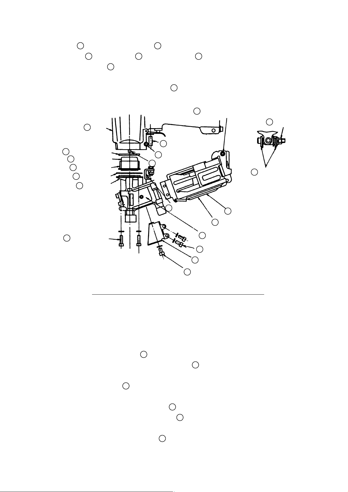
Bolts 73, retaining the Tail Cover 36, the Piston
Damper
and Packing (A)
27
, Damper Ring 28, Cylinder Damper 26,
29
, can be removed. (see Fig. 9)
(Please note that the M6 x 20 Hexagon Socket Hd. Bolts
can be easily removed if the Nail Guide
23
Body
26
Cylinder Damper
27
Piston Damper
28
Damper Ring
29
Packing (A)
36
Tail Cover
13
92
is left open.)
43
Safety Plunger (B)
25
Roll Pin
Piston
55
Safety Lever
65
M5 x 30 Hex. Socket Bolt
83
81
Magazine
Cover
56
M5 Nut
2
Washer (2 pcs.)
73
M6 x 20
Hex. Socket Bolt
(4 pcs.)
57
58
Safety Guard
59
M5 x 10 Hex. Socket Bolt
Fig. 9 Piston damper, Packing (A)-di sassembl y/reassembly
(2) Assembly:
Assembly can be accomplished by following the disassembly
procedures in reverse. However, special attention should
be given to the following items:
Ensure that the Piston Ass’y 13 is positioned so its
z#
semicircular groove faces toward the Magazine
81
(see Fig. 10 below).
As Safety Plunger (B) 43, may drop out during dis-
z#
assembly, ensure it is properly assembled.
92
Nail Guide
M5 x 12 Hex. Socket Bolt (2 pcs.)
Ensure that the air vent on Packing (A) 21 is properly
z#
aligned with the air vent on the Tail Cover
Assembly can be more easily accomplished if the two
z#
M5 x 12 Hexagon Socket Hd. Bolts
36
.
57
which connect
− 2 −
Page 3
the Tail Cover 36 and Magazine 81 are loosened.
Assemble the Body 23, Tail Cover 36, and
z#
81
Magazine
in the following sequence:
(a) Loosely assemble the Body
23
and Tail Cover
with the four M6 x 20 Hexagon Socket Hd. Bolts 73.
(b) After assembling the Safety Lever Ass’y
loosely assemble the Magazine
Cover
Hd. Bolts
36
with the two M5 x 12 Hexagon Socket
57
.
(c) Finally, assemble the Magazine
81
81
55
,
to the Tail
to the Body
with the M5 x 30 Hexagon Socket Hd. Bolt 65,
tightening it to rated torque.
(d) In the sequence of (b) (a) (c), ensure that all bolts
are securely tightened to rated torque.
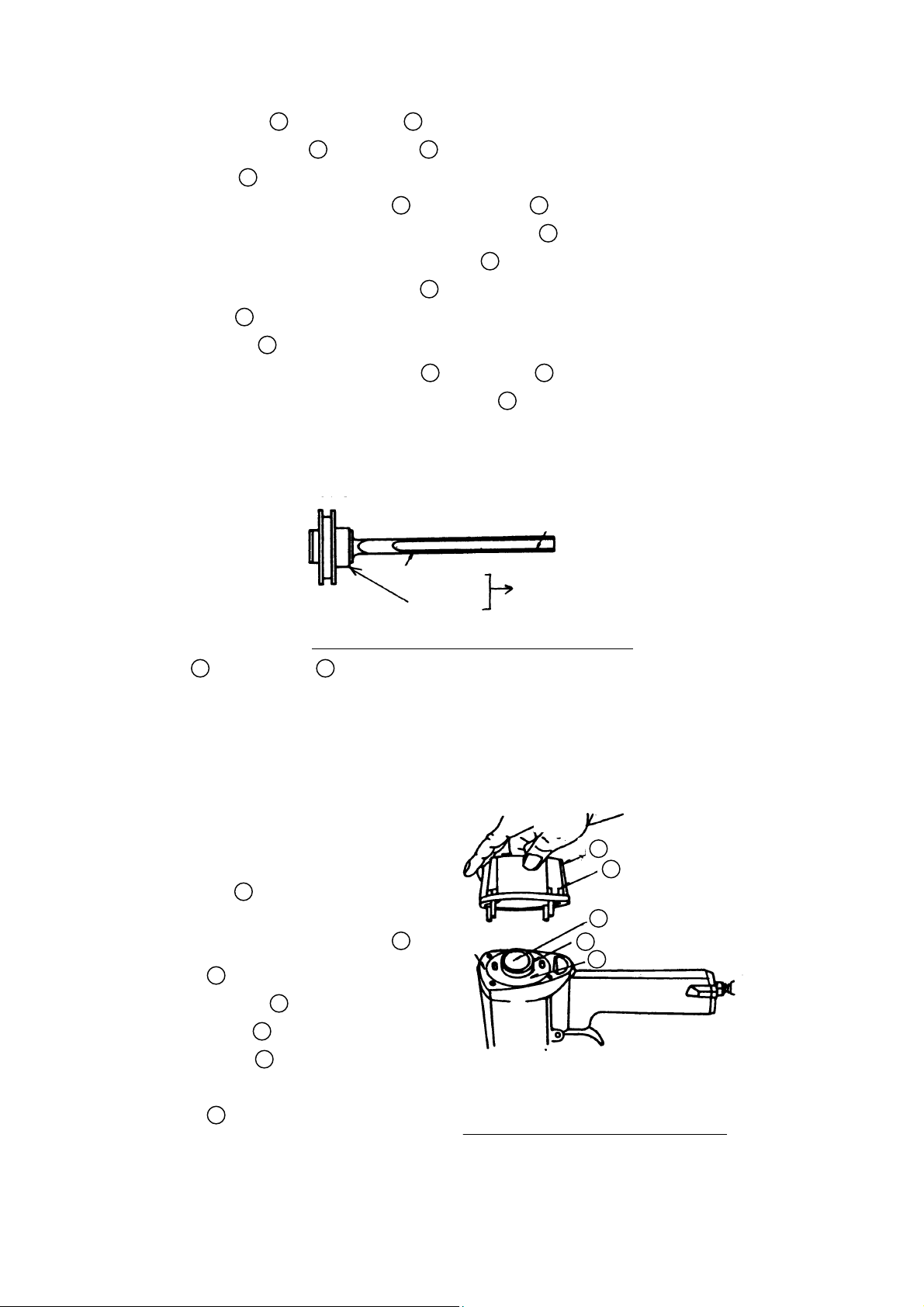
Drive Bit
Piston
Piston Ass’y
Fig. 10 Semi-circle groove of piston ass’y
36
23
Semicircular Groove
B. Cylinder 18, Piston Ass’y 13, etc.:
Tools Required:
5 mm Hexagon Bar
z#
Spanner (for M6 bolt)
(1) Disassembly:
By removing the
z#
four M6 x 25
Hexagon Socket
Hd. Bolts
4
and taking off the
Exhaust Cover
Ass’y
Cylinder Plate
Packing (B)
the Cylinder
6
and
7
18
16
,
,
,
and the Piston
Ass’y
13
can be
removed. (see
7
Packing (B)
6
Exhaust Cover
4
M6 x 25
Hex. Socket
Bolt
13
Piston
18
Cylinder
16
Cylinder Plate
Fig. 11 Disassembly of Upper
Part of main body
Fig. 11)
− 3 −
Page 4
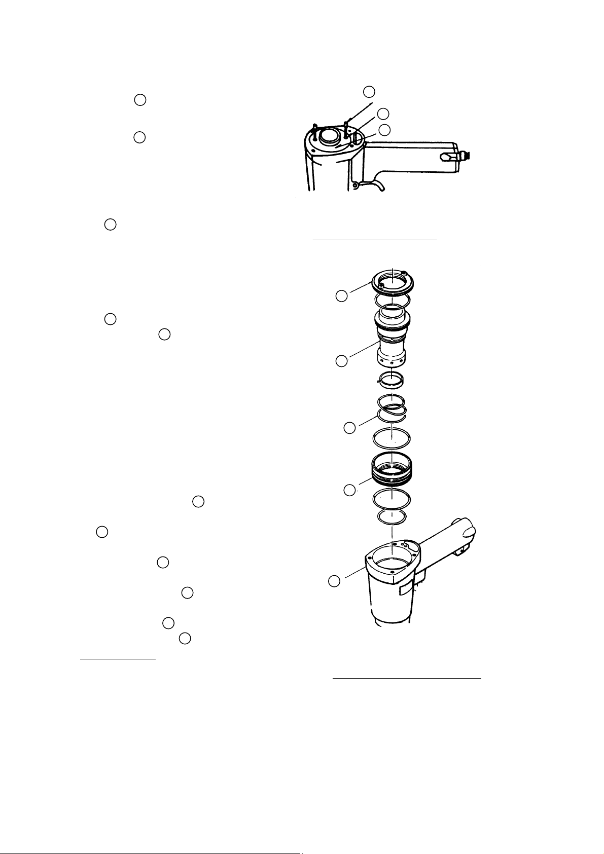
If it is difficult to
z#
remove the Cylinder
Plate
16
, insert
two of the M6 x 25
Hexagon Socket Hd.
Bolts 4 part way
into the matching M6
holes on the Cylinder
Plate, and pull upwards while turning.
(see Fig. 12)
The Cylinder Spring
20
and other components which
constitute the Output
Section (see Fig. 13)
can then be removed.
Should it be difficult
z#
to remove the Cylinder
18
, first remove the
36
Tail Cover
, and
push the Cylinder
upwards and out from
below.
(2) Assembly:
Assembly can be accomplished by following the
disassembly procedures
in reverse. During
assembly, ensure that
the semicircular groove
on the Piston Ass’y
faces toward the Magazine
81
(as described above),
and that the air vent on
7
Packing (B)
is properly aligned with the air
vent on the Body
23
13
.
Fig. 12 Removal of
Cylinder plate
Cylinder
Cylinder spring
Cylinder guide
Body
23
4
M6 x 25
Cylinder plate
16
18
20
21
Hex. Socket Bolt
16
M6 threaded hole
16
Cylinder Plate
C. Head Cap Ass’y
Valve Rubber Ass’y
11
and
10
:
Tools Required:
4 mm Hexagon Bar Spanner (for M5 bolt)
z#
(1) Disassembly:
Remove the Exhaust Cover Ass’y (as described above).
z#
Fig. 13 Main body output
disassembly
− 4 −
Page 5

Take out the two M5 x 35
z#
Hexagon Socket Hd.
Bolts
1
and remove the
Head Cap Ass’y
Valve Rubber Ass’y
and Packing (C)
(see Fig. 14)
(2) Assembly:
Assembly can be accom-
z#
plished by following the
11
8
M5 x 35
Hexagon Socket
1
,
10
,
Bolt
Top Cover
3
.
Exhaust
Cover
6
disassembly procedures
in reverse. During
assembly, be very careful
not to damage the O-Rings.
1-2. Valve Section:
A. Trigger Valve Bushing and
Safety Valve Bushing:
Tools Required:
φ
3 Roll Pin Remover
z#
Minus-Hd. Screwdriver
z#
(1) Disassembly:
Remove the Magazine
z#
section and Tail Cover
section as described in
section 1-1 above.
Take out the two φ 3 x 30
z#
Roll Pins
Remove the Trigger 42,
z#
25
Trigger Plunger
Safety Plunger (B)
(see Fig. 15)
Insert the minus-hd.
z#
screwdriver into the
groove of the Trigger Valve Bushing
Packing (C)
Valve rubber
Ass’y
Head cap
Ass’y
8
10
11
Fig. 14 Disassembly of main
body, upper parts
32
81
Plunger Spring
36
25
φ 3 x 30
Roll pin
39
.
49
, and
43
.
Safety plunger (A)
40
Safety valve bushing
47
Valve plate
48
Trigger Valve
bushing
49
Trigger
plunger
42
Trigger
25
φ 3 x 30
Roll pin
43
Safety
plunger (B)
Fig. 15 Disassembly of Valve
48
, and loosen it
by turning it counterclockwise, being careful not to
damage the groove. (see Fig. 15)
After the Trigger Valve Bushing 48 has been loosened,
z#
the Safety Valve Bushing
40
and Trigger Valve Bushing
− 5 −
48
Page 6

can be removed by pulling the Safety Valve Bushing 40.
(see Fig. 15)
(2) Assembly:
Assembly can be
z#
accomplished
by following
the disassembly
procedures in
reverse. During
assembly, be
vary careful not
to twist the
Plunger Spring
37
or damaged the
external O-Rings.
B. Adjustment of the Safety
Assembly
55
(see Fig. 16)
39
Safety
Plunger (A)
43
Safety
Plunger (B)
54
Safety Bolt
,
56
M5 Nut
55
36
Tail Cover
)
″
Safety Ass’y
(1) The Safety Ass’y
can be adjusted by
loosening the M5 Nut
56
and turning the
Safety Bolt
54
(2) Perform adjustment
to a point where the
pressure of Safety
Plunger (B)
43
pushing up Safety
Plunger (A)
39
be felt when the Safety Ass’y
the lower end of the Tail Cover
from the lower end of the Safety Ass’y
(0.118″ ± 0.020″).
1-3. Nail Feeder Section:
92
A. Nail Guide
(see Fig. 17):
Tools Required:
φ
3 Roll Pin Puller
z#
M3 Spanner
z#
(1) Disasembly:
Remove the φ 2 x 15 Split Cotter Pin 86 from the Tail
z#
.
can
55
Fig. 16 Safety assembly
55
is raised. At this point,
36
should be separated
55
by 3 mm ± 0.5 mm
± 0.020
″
3 ± 0.5mm
(0.118
adjustment
− 6 −
Page 7

Cover 36, take out the Nail Guide 85, and
remove the Nail Guide Ass’y
Loosen the M3 Nylon Nut 93, and remove the Stopper
z#
Bolt
Take out the φ 3 x 30 Roll Pin 25, and remove the Main
z#
Nail Stopper
Spring
To disassemble the Guide Lock 79, pull out the
z#
φ
3 x 10 Roll Pin
and the Spring 80.
Tail Cover
Nail Guide Shaft
92
.
90
and the two Thrust Washers 91.
74
, Sub Nail Stopper 75, Main Stopper
76
, and Sub Stopper Spring 77.
31
, and remove the Guide Lock
74
Main Nail Stopper
36
75
Sub-Nail Stopper
76
85
86
φ 2 Split
Cotter Pin
Thrust Washer
77
Sub-Stopper
Spring
25
φ 3 x 30 Roll Pin
Stopper Bolt
79
Main Stopper Spring
90
92
Nail Guide
91
93
78
M3 Nylon Nut
Lock Shaft
79
Guide Lock
80
Spring
31
φ 3 x 10 Roll Pin
Fig. 17 Disassembly and Reassembly of Nail Guide
(2) Assembly:
Assembly can be accomplished by following the disassembly
procedures in reverse. However, special attention should
be given to the following items:
Carefully clean any plastic particles or dust from the
z#
groove on the Nail Guide
When re-inserting the φ 3 x 30 Roll Pin 25, first tempo-
z#
rarily tighten the Stopper Bolt
Spring
76
and Sub Stopper Spring 77 in position. This
92
prior to assembly.
90
to hold the Main Stopper
will facilitate assembly.
− 7 −
Page 8

With the Thrust Washers 91, perform adjustment so
z#
that the protrusion of the Sub Nail Stopper
75
is within
2.3 mm ± 0.5 mm (0.09″ ± 0.020″), as illustrated in
Fig. 18.
91
90
Stopper bolt
Thrust Washer
Fig. 18 Assembly of Sub-nail stopper section
B. Safety Ass’y
55
By removing the φ 3 x 30 Roll Pin 25 as described in section
1-2, and then removing the Safety Guard
Ass’y
55
and the Safety Spring 53 can be removed.
58
, the Safety
)
″
± 0.020
″
2.3 ± 0.5mm
(0.09
70
C. Feed Pist on
, Main Feeder 34, and Sub Feeder 35:
Tools Required:
φ
2.5 and φ 3 Roll Pin Removers
z#
4 mm Hexagon Bar Spanner (for M5 bolt)
z#
(1) Disassembly:
Disassemble the Tail Cover 36 from the Body 23 as
z#
described in section 1-1, and remove the Magazine
and the Safety Ass’y 48. (see Fig. 19)
81
Magazine Ass’y
55
Safety Ass’y
53
Safety Spring
25
φ 3 x 30 Roll Pin
59
M5 x 10 Hex. Socket
Bolt (1 pc.)
58
Safety Guard
57
M5 x 12
Hex. Socket
Bolt (2 pcs.)
83
23
Body Ass’y
36
Tail Cover
73
M5 x 20 Hex. Socket Bolt (4 pcs.)
Fig. 19 Tail Cover Disassembly
− 8 −
Page 9

Take out the φ 2.5 x 10 Roll Pin from the Feed Piston 70,
z#
loosen the two M5 x 12 Hexagon Socket Hd. Bolts
67
and remove the Feed Piston Cover
68
. (see Fig. 20)
Pressing the Feed Piston 70 with a finger (as indicated
z#
by arrow mark
1
in Fig. 20), turn the Feeder
and Packing (E)
35
1/4 turn (arrow mark 2), and pull out the Feeder Shaft
33
(arrow mark 3). The Feed Piston 70, Feed
Spring
and Sub Feeder
72
, Main Feeder 34, Main Feeder Spring 30,
34
Main Feeder
30
Main Feeder Spring
35
can then be removed. (see Fig. 20)
(φ 2.5 Roll Pin Hole)
70
Feed Piston (72 Feed Spring)
68
33
Feeder Shaft
1
57
,
Packing (E)
67
Feed Piston Cover
35
Sub Feeder
71
φ 2.5 x 10 Roll Pin
Fig. 20 Feed Piston Disassembly
Take out the φ 3 x 10 Roll Pin 31 from the Feeder
z#
Shaft
Sub Feeder
33
, and disassemble the Feeder Shaft 33,
35
, and Sub Feeder Spring 32. (see
Fig. 21)
30
Main Feeder Spring
33
Feeder Shaft
57
M5 x 12 Hex. Socket Bolt (2 pcs.)
69
34
Main Feeder
72
Feed Spring
70
Feed Piston
O-Ring (P16)
31
φ 3 x 10 Roll Pin
32
Sub Feeder Spring
Fig 21 Feed Piston, Main Feeder, and
35
Sub-Feeder
Sub-Feeder Disassembly
− 9 −
Page 10

(2) Assembly:
Assembly can be accomplished by following the disassembly
procedures in reverse. However, special attention should
be given to the following items:
Ensure that the Sub
z#
Feeder 35 and the
Feeder Shaft
are assembled so
33
33
Feeder Shaft
that the groove on
the shaft is on the
right-hand side as
illustrated in
Fig. 22.
In assembling the
z#
31
φ 3 x 10 Roll Pin
Fig. 22 Sub-feeder
Feed Piston section,
first put the Feed
Spring 72 onto the
Feed Piston 70,
ensuring that the
O-Ring (R16)
69
is properly fitted to
the O-Ring groove
on the Piston. Next,
while pressing the
Feed Piston 70 in
with a finger as
illustrated Fig. 23,
insert the Main
Feeder 34 from
Fig. 23 Feed piston assembly
below, and set the
Main Feeder Spring 30.
Then, insert the
Feeder Shaft
33
through the holes of
the Main Feeder
Spring 30, Main
Feeder 34, and the
Feed Piston 70.
Main Feeder
Foot
Finally, align the
φ
2.5 groove on the
Fig. 24 Installing Main
Feeder Shaft 33 with
the φ 2.5 hole in the
Feed Piston 70, and insert the φ 2.5 x 10 Roll Pin 71.
At this time, ensure that the Main Feeder Spring
30
spring hook section securely catches on the foot of the
Main Feeder 34, as illustrated in Fig. 24.
For assembly of the Body 23 and Magazine 81, please
z#
refer to section 1-1.
φ 2.5 Groove
32
Sub Feeder Spring
35
Sub Feeder
assembly
34
Main Feeder
Feeder Piston is
pushed up
33
Feeder Shaft
Main Feeder
Spring Hook
feeder spring
70
Feeder Piston
− 10 −
Page 11

1-4. Magazine Section:
Tools Required:
5 mm Hexagon Bar Spanner
z#
(1) Disassembly:
As described in section 1-1, remove the M5 x 30 Hexagon
z#
Socket Hd. Bolt
Bolts
57
, and the M5 x 10 Hexagon Socket Hd. Bolts 59,
and take off the Magazine Ass’y
Open the cover, remove the M5 Hexagon Socket Round Hd.
z#
Screw
83
Remove the M5 x 25 Hexagon Socket Hd. Bolt 66, push
z#
84
, and disassemble the Washer 64, Nail Holder
, and Holder Spring 82.
out the Magazine Stopper
the Magazine Stopper
the Collar
65
, the two M5 x 12 Hexagon Socket Hd.
62
. (see Fig. 25)
81
.
61
from below, and disassemble
61
, Magazine Lock Spring 60, and
(2) Assembly:
Assembly can be accomplished by following the disassembly
procedures in reverse.
CAUTION: The Magazine Lock Spring
into the Magazine Stopper
60
must be inserted
61
from above.
81
Magazine Ass’y
82
Holder Spring
66
M5 x 25
Hex. Socket Bolt
84
64
Washer
83
Nail Holder
M5 Hex. Socket Screw
Fig. 25 Magazine ass’y disassembly
60
Magazine Lock Spring
61
Magazine Stopper
62
Collar
56
M5 Nut
− 11 −
Page 12

1-5. Assembly Precauti ons:
The O-Rings and their associated parts should be carefully
z#
lubricated. Hitachi Electric Tool Grease or Hitachi Motor
Grease is recommended. When fitting the O-Rings, particular
attention should be exercised to avoid damaging the O-Rings
and allowing drift and dust from entering the assembly.
Damaged, worn, or deformed packings should be replaced, and
z#
the assembly should be checked for air leaks.
Ensure that no foreign matter is allowed to enter the Valve
z#
Section.
The sliding portions of the Nail Feeder should be lubricated
z#
with grease or accessory oil.
The table below lists the appropriate tightening torque for
z#
various bolts, nuts and screws.
Table 8
Type of Screw Tightening Torque
M6 Hex. Socket Bolt
M5 Hex. Socket Bolt
M5 Hex. Socket Screw
M5 Nut
M3 Nylon Nut
100 ± 8 kg-cm (7.2 ± 0.6 ft. lb)
65 ± 5 kg-cm (4.7 ± 0.4 ft. lb)
43 ± 3 kg-cm (3.1 ± 0.2 ft. lb)
35 ± 3 kg-cm (2.5 ± 0.2 ft. lb)
9 ± 0.7 kg-cm (0.7 ± 0.05 ft. lb)
1-6. Checks After Assembl y:
Manually check the Main Feeder, Sub Feeder, Main Nail Stopper,
z#
and Sub Nail Stopper to ensure they are properly assembled and
function correctly.
Check each component for air leaks.
z#
Check for reliable performance of the Feed Piston under pneumatic
z#
pressure of 3 kg/cm
2
(43 psi). (Perform this check with the Nail
Guide open and with idling operation.)
Nailing operation at 4 kg/cm2 (60 psi) should not result in idling
z#
operation or bending of the nails.
Check the tightening torque of all nuts, bolts and screws.
z#
− 12 −
 Loading...