

Hitachi RAS-4FSVN2E, RAS-6FSVN2E, RAS-4FSNY2E, RAS-5FSVN2E, RAS-5FSNY2E Technical Catalogue
...Page 1
SET-FREE MINI series
Technical Catalogue
RAS-(4-6)FSVN2E
RAS-(4-6)FSNY2E
Page 2

Page 3

Index
I n d e x
1
General information
2
Features and benets
3
General data
4
Capacities and selection data
Acoustic characteristic curves
Working range
General dimensions
Refrigerant cycle
Piping work and refrigerant charge
Electrical wiring
Optional functions
5
6
7
8
9
10
11
III
TCGB0068 rev.1 - 08/2012
12
Troubleshooting
Page 4

Index
IV
TCGB0068 rev.1 - 08/2012
Page 5

General Index
Index
1. General information ...................................................................................................1
1.1. General information .................................................................................................................................2
1.1.1. General notes .............................................................................................................................................. 2
1.1.2. Introduction .................................................................................................................................................. 2
1.1.3. Environment-friendly units ........................................................................................................................... 2
1.2. Applied symbols ......................................................................................................................................3
1.3. Product guide ..........................................................................................................................................4
1.3.1. Classication of outdoor unit models ........................................................................................................... 4
1.3.2. Classication of indoor unit models ............................................................................................................. 4
1.3.3. Product guide: Outdoor units ....................................................................................................................... 5
1.3.4. Product guide: Indoor units .......................................................................................................................... 6
1.3.5. Accessory code list .................................................................................................................................... 10
2. General data ............................................................................................................. 11
2.1. General data..........................................................................................................................................12
2.1.1. General conditions ..................................................................................................................................... 12
2.1.2. RAS-4FS(V)N(Y)2E ................................................................................................................................... 13
2.1.3. RAS-5FS(V)N(Y)2E ................................................................................................................................... 14
2.1.4. RAS-6FS(V)N(Y)2E ................................................................................................................................... 15
2.2. Component data ....................................................................................................................................16
2.2.1. RAS-(4-6)FSVN2E .................................................................................................................................... 16
2.2.2. RAS-(4-6)FSNY2E .................................................................................................................................... 16
2.2.3. Compressors ............................................................................................................................................. 17
2.3. Electrical data .......................................................................................................................................18
2.3.1. Considerations ........................................................................................................................................... 18
2.3.2. RAS-(4-6)FS(V)N(Y)2E ........................................................................................................................... 18
3. Features and benefits ..............................................................................................19
3.1. Selection benets .................................................................................................................................. 20
3.1.1. Wide range of units, accessories and remote controls .............................................................................. 20
3.1.2. High number of connectable indoor units .................................................................................................. 22
3.1.3. Individual operation ................................................................................................................................... 23
3.1.4. Assisted air conditioning installation design by Hi-Tool kit selection software ........................................... 23
3.2. Installation benets................................................................................................................................24
3.2.1. Easy and exible unit installation ............................................................................................................... 24
3.2.2. Easy and exible electrical installation ...................................................................................................... 24
3.2.3. Easy and exible control connection (Central Station, BMS Interface, CS-NET WEB) ............................. 26
3.3. Start-up benets .................................................................................................................................... 27
3.3.1. Automatic start-up test ............................................................................................................................... 27
3.3.2. Service verication .................................................................................................................................... 28
3.4. Functionality benets.............................................................................................................................29
3.4.1. Expanded temperature range .................................................................................................................... 29
3.4.2. Wide capacity range .................................................................................................................................. 30
3.4.3. Increased maximum piping length ............................................................................................................. 30
V
TCGB0068 rev.1 - 08/2012
Page 6

General Index
3.4.4. Advanced technology ................................................................................................................................ 31
3.5. Maintenance benets ............................................................................................................................40
3.5.1. Minimum maintenance .............................................................................................................................. 40
3.5.2. Easy accessibility ...................................................................................................................................... 40
3.5.3. Alarm codes ............................................................................................................................................... 40
3.5.4. SMS alarm ................................................................................................................................................. 40
3.5.5. Availability of maintenance tools ............................................................................................................... 40
4. Capacities and selection data ................................................................................. 41
4.1. System selection procedure .................................................................................................................. 42
4.1.1. SET FREE MINI system posibilities .......................................................................................................... 42
4.1.2. Selection parameters ................................................................................................................................. 45
4.1.3. Selection procedure ................................................................................................................................... 45
4.2. Cooling capacity tables .........................................................................................................................51
4.2.1. Cooling capacity curve .............................................................................................................................. 51
4.2.2. Nominal cooling capacity tables ................................................................................................................ 52
4.2.3. Cooling capacity tables according to total power of combined indoor units .............................................. 53
4.3. Heating capacity tables .........................................................................................................................68
4.3.1. Heating capacity curve .............................................................................................................................. 68
4.3.2. Nominal heating capacity tables ................................................................................................................ 69
4.3.3. Heating capacity tables according to total power of combined indoor units .............................................. 70
4.4. Correction factors .................................................................................................................................. 86
4.4.1. Piping length correction factor ................................................................................................................... 86
4.4.2. Defrost correction factor ............................................................................................................................ 89
4.4.3. Correction ratio due to humidity (CR) ........................................................................................................ 89
5. Acoustic characteristic curves ............................................................................... 91
5.1. Overall sound level ................................................................................................................................92
5.2. Sound data ............................................................................................................................................ 93
6. Working range ..........................................................................................................95
6.1. Working range ....................................................................................................................................... 96
6.1.1. Power supply ............................................................................................................................................. 96
6.1.2. Temperature range .................................................................................................................................... 96
7. General dimensions ................................................................................................. 97
7.1. Dimensions............................................................................................................................................98
7.2. Service space ........................................................................................................................................99
8. Refrigerant cycle ....................................................................................................101
8.1. RAS-(4-6)FS(V)N(Y)2E ....................................................................................................................... 102
9. Piping work and refrigerant charge .....................................................................103
9.1. Refrigerant piping selection .................................................................................................................104
9.1.1. Piping size selection ................................................................................................................................ 104
9.1.2. Multi-kit or distributor selection ................................................................................................................ 104
VI
TCGB0068 rev.1 - 08/2012
Page 7

General Index
9.2. Refrigerant piping range ......................................................................................................................104
9.2.1. Refrigerant piping length ......................................................................................................................... 104
9.2.2. Refrigerant piping size ............................................................................................................................. 107
9.3. Distribution method .............................................................................................................................108
9.3.1. Header branch piping system .................................................................................................................. 108
9.3.2. Line branch piping system ....................................................................................................................... 109
9.3.3. Combination branch piping system ..........................................................................................................111
9.4. Piping materials and connection ......................................................................................................... 112
9.4.1. Copper pipes and sizes ............................................................................................................................112
9.4.2. Pipe connection ........................................................................................................................................113
9.4.3. Insulation ..................................................................................................................................................113
9.5. Refrigerant charge amount.................................................................................................................. 114
9.5.1. Refrigerant charge before shipment (W0 (kg)) ..........................................................................................114
9.5.2. Additional refrigerant charge calculation method .....................................................................................114
9.5.3. Additional refrigerant charge calculation example ...................................................................................115
9.6. Caution in case of refrigerant leakage................................................................................................. 116
9.6.1. Maximum permitted concentration of hydrouorocarbon (HFC) ...............................................................116
9.6.2. Calculation of refrigerant concentration ....................................................................................................116
9.6.3. Countermeasure for refrigerant leakage ...................................................................................................116
10. Electrical wiring ..................................................................................................... 119
10.1. General information ............................................................................................................................. 120
10.1.1. General notes ..........................................................................................................................................120
10.1.2. General verications ................................................................................................................................ 120
10.2. Setting of DIP switches and RSW switches ........................................................................................ 122
10.3. Common wiring ...................................................................................................................................124
10.3.1. Electrical wiring between outdoor and indoor unit ................................................................................... 124
10.3.2. Wiring size ...............................................................................................................................................125
10.4. H-LINK II system .................................................................................................................................126
10.4.1. Application ...............................................................................................................................................126
10.4.2. Features .................................................................................................................................................. 126
10.4.3. Specications .......................................................................................................................................... 126
10.4.4. DIP switch setting for multiple H-LINK system ........................................................................................ 127
10.4.5. Examples of the system of connection between H-LINK and H-LINK II units ......................................... 128
10.4.6. Examples of H-LINK II system ................................................................................................................. 129
11. Optional functions ................................................................................................. 131
11.1. RAS-(4-6)FS(V)N(Y)2E ....................................................................................................................... 132
11.2. For operation with CS-NET WEB ........................................................................................................ 133
12. Troubleshooting ..................................................................................................... 135
12.1. On-screen displays during abnormal operation .................................................................................. 136
12.2. Alarm codes ........................................................................................................................................137
VII
TCGB0068 rev.1 - 08/2012
Page 8

Page 9

1 General information
G e n e r a l i n f o r m a t i o n
1.
Index
1.1. General information .................................................................................................................................2
1.1.1. General notes .............................................................................................................................................. 2
1.1.2. Introduction .................................................................................................................................................. 2
1.1.3. Environment-friendly units ........................................................................................................................... 2
1.2. Applied symbols ......................................................................................................................................3
1.3. Product guide ..........................................................................................................................................4
1.3.1. Classication of outdoor unit models ........................................................................................................... 4
1.3.2. Classication of indoor unit models ............................................................................................................. 4
1.3.3. Product guide: Outdoor units ....................................................................................................................... 5
1.3.4. Product guide: Indoor units .......................................................................................................................... 6
1.3.5. Accessory code list ...................................................................................................................................... 9
1
1
TCGB0068 rev.1 - 08/2012
Page 10

1 General information
1.1 General information
1.1.1 General notes
No part of this publication may be reproduced, copied, led or transmitted in any shape or form without the permission of
HITACHI Air Conditioning Products Europe, S.A.
Within the policy of continuous improvement of its products, HITACHI Air Conditioning Products Europe, S.A. reserves the
right to make changes at any time without prior notication and without being compelled to introducing them into products
subsequently sold. This document may therefore have been subject to amendments during the life of the product.
HITACHI makes every effort to offer correct, up-to-date documentation. Despite this, printing errors cannot be controlled by
HITACHI and are not its responsibility.
As a result, some of the images or data used to illustrate this document may not refer to specic models. No claims will be
accepted based on the data, illustrations and descriptions included in this manual.
No type of modication must be made to the equipment without prior, written authorisation from the manufacturer.
1.1.2 Introduction
Hitachi presents the inverter-driven home central air-conditioning SET FREE mini series product, which is characterized
by energy-saving, high efciency, comfort, environmental protection, stability and reliability. In order to meet the requirement of increasing the control intelligence of equipment and of comfort, the intelligent control, energy-saving operation and
comfortableness are more important. Especially the business building, building ofce, villa, apartment and residential area
etc, need an intelligent and confortable environment through all year. The better air conditioning solution can be provided
for these buildings by inverter- driven and scroll compressor that the structure can been improved.
1.1.3 Environment-friendly units
This range of HITACHI outdoor units uses environmentally-friendly
R410A gas refrigerant, and the RoHS and Green Dot regulations are
applied throughout the manufacturing and installation process to reect
HITACHI’s awareness of environmental respect and commitment.
R410A is totally environmentally-friendly since it does not contain
any substances that damage the ozone layer: ODP (ozone depleting product) =0.
2
TCGB0068 rev.1 - 08/2012
Page 11
1 General information
1.2 Applied symbols
During normal air conditioning system design work or unit installation, greater attention must be paid in certain situations
requiring particular care in order to avoid damage to the unit, the installation or the building or property.
Situations that jeopardise the safety of those in the surrounding area or that put the unit itself at risk will be clearly indicated
in this manual.
To indicate these situations, a series of special symbols will be used to clearly identify these situations.
Pay close attention to these symbols and to the messages following them, as your safety and that of others depends on it.
D A N G E R
• The text following this symbol contains information and instructions relating directly to your safety and physical wellbeing.
• Not taking these instructions into account could lead to serious, very serious or even fatal injuries to you and
others in the proximities of the unit.
In the texts following the danger symbol you can also nd information on safe procedures during unit installation.
C A U T I O N
• The text following this symbol contains information and instructions relating directly to your safety and physical wellbeing.
• Not taking these instructions into account could lead to minor injuries to you and others in the proximities of
the unit.
• Not taking these instructions into account could lead to unit damage.
In the texts following the caution symbol you can also nd information on safe procedures during unit installation.
N O T E
• The text following this symbol contains information or instructions that may be of use or that require a more
thorough explanation.
• Instructions regarding inspections to be made on unit parts or systems may also be included.
1
3
TCGB0068 rev.1 - 08/2012
Page 12

1 General information
1.3 Product guide
1.3.1 Classication of outdoor unit models
Unit type (Outdoor unit):
Position-separating hyphen (xed)
Compressor power (HP): 4, 5, 6
FS = SET-FREE system
V = Single phase unit (1~ 230V 50Hz)
N = R410A refrigerant
Y = Three phase unit (3N~ 400V 50Hz)
Series
RAS – X FS (V) N (Y) 2 E
1.3.2 Classication of indoor unit models
E = Made in Europe
Unit type (indoor unit): RCI, RCIM, RCD, RPC, RPI, RPIM, RPK, RPF, RPFI
Position-separating hyphen (xed)
Capacity (HP): 0.8, 1, 1.5, 2, 2.5, 3, 4, 5, 6
FS = SYSTEM FREE
N = R410A refrigerant
H = Hotel (RPK-(1.0/1.5) only)
2/3/4 = series
E = Made in Europe
M = Made in Malaysia
– = Made in Japan
i = Version up (RCI only)
DU = Drain Up (RPIM only)
XXX – X.X FS N (H) X (X) i (-DU)
4
TCGB0068 rev.1 - 08/2012
Page 13
1 General information
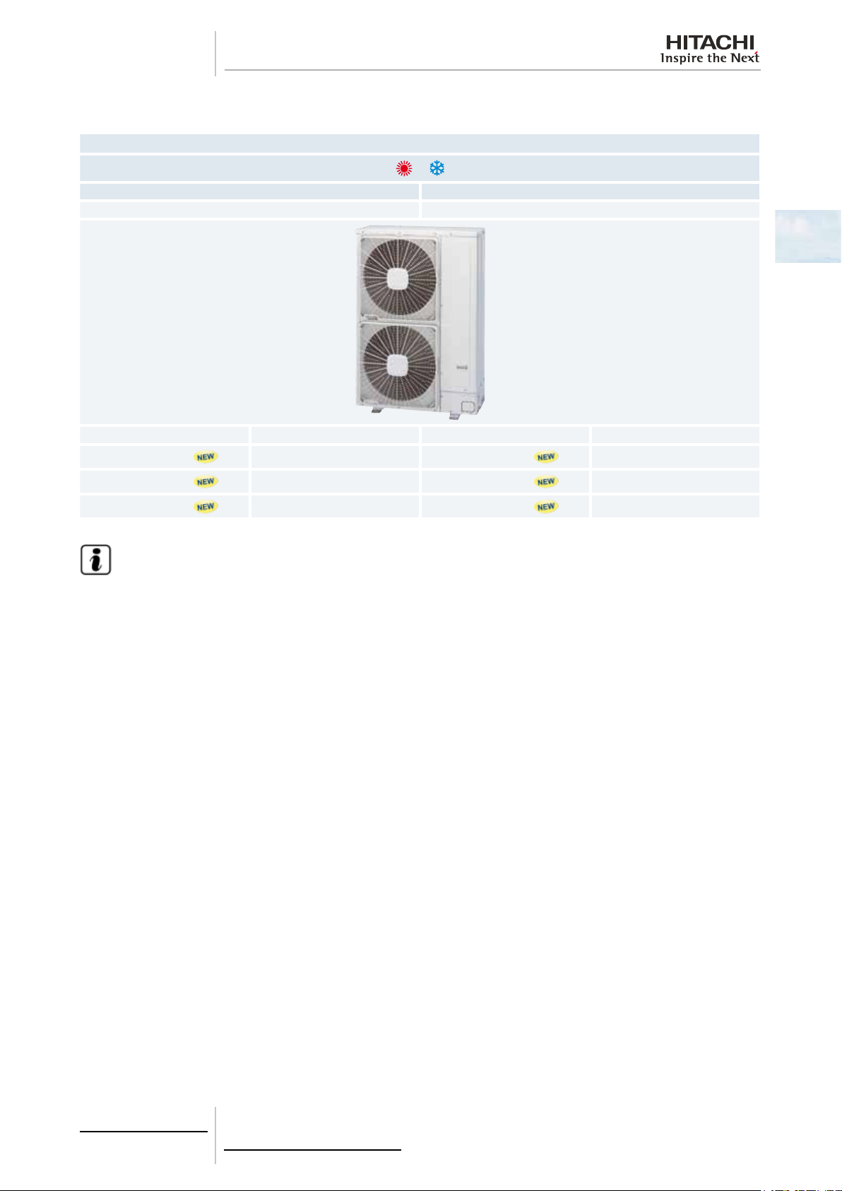
1.3.3 Product guide: Outdoor units
1~ 3N~
FSVN2E FSNY2E
Unit Code Unit Code
RAS-4FSVN2E
RAS-5FSVN2E
RAS-6FSVN2E
7E320007
7E320008
7E320009
Outdoor units
RAS-4FSNY2E
RAS-5FSNY2E
RAS-6FSNY2E
1
7E320107
7E320108
7E320109
N O T E
Check the exact classication for each unit (model, type, power and series) in Classication of outdoor unit mo-
dels.
5
TCGB0068 rev.1 - 08/2012
Page 14
1 General information
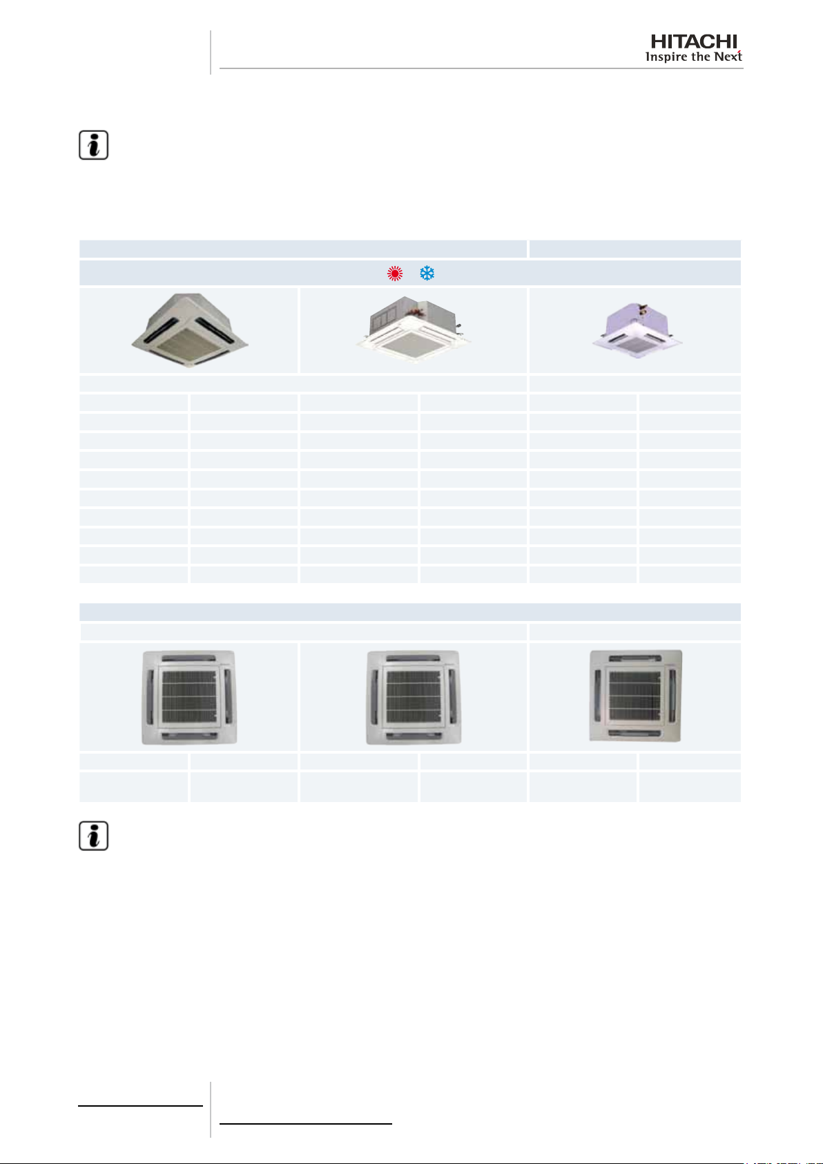
1.3.4 Product guide: Indoor units
N O T E
• The indoor unit models and codes are the last updated at time of publication; other previous models and coming developments could be available for combination with this outdoor unit series.
• Check the exact classication for each unit (model, type, power and series) in Classication of indoor unit
mo dels.
RCI RCIM
4-way cassette 4-way cassette (compact)
Unit Code Unit Code Unit Code
RCIM-0.8FSN2 60278010
RCI-1.0FSN3Ei 7E403014 RCI-1.0FSN3 (*) 60278119 RCIM-1.0FSN2 60278011
RCI-1.5FSN3Ei 7E403015 RCI-1.5FSN3 (*) 60278120 RCIM-1.5FSN2 60278013
RCI-2.0FSN3Ei 7E403016 RCI-2.0FSN3 (*) 60278121 RCIM-2.0FSN2 60278014
RCI-2.5FSN3Ei 7E403017 RCI-2.5FSN3 (*) 60278122
RCI-3.0FSN3Ei 7E403018 RCI-3.0FSN3 (*) 60278123
RCI-4.0FSN3Ei 7E403020 RCI-4.0FSN3 (*) 60278124
RCI-5.0FSN3Ei 7E403021 RCI-5.0FSN3 (*) 60278125
RCI-6.0FSN3Ei 7E403022 RCI-6.0FSN3 (*) 60278126
Panels
RCI RCIM
P-N23NA 70531000 P-AP160NA1 60297215 P-N23WAM 60197160
P-AP160NAE
(With motion sensor)
60297217
N O T E
• The RCI and RCIM models must be used in combination with the panels indicated above.
• (*): Series available from October 2012.
6
TCGB0068 rev.1 - 08/2012
Page 15
1 General information
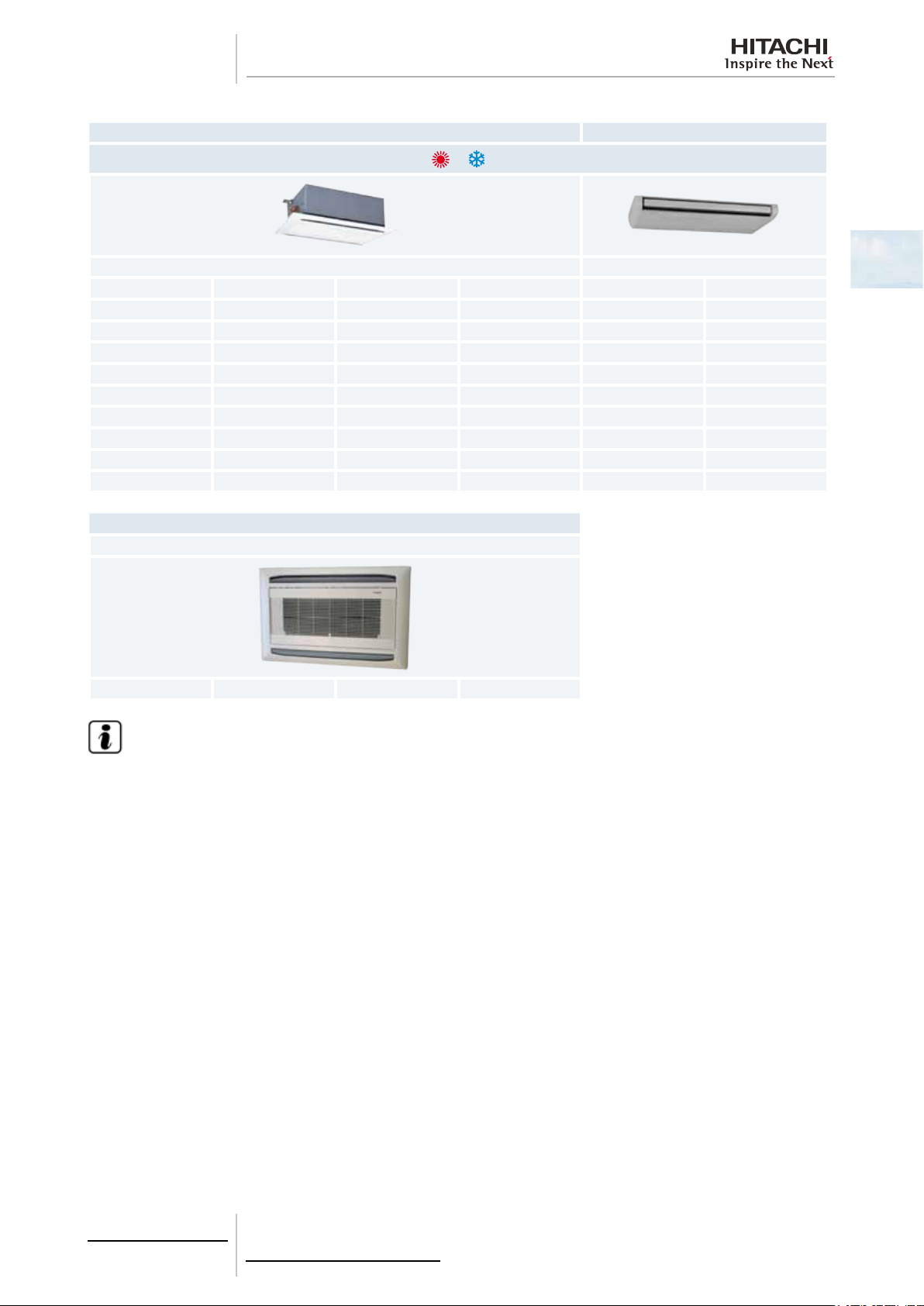
RCD RPC
2-way cassette Ceiling type
Unit Code Unit Code
RCD-1.0FSN2 60278029
RCD-1.5FSN2 60278030
RCD-2.0FSN2 60278031 RPC-2.0FSN2E 7E440003
RCD-2.5FSN2 60278032 RPC-2.5FSN2E 7E440004
RCD-3.0FSN2 60278033 RPC-3.0FSN2E 7E440005
RCD-4.0FSN2 60278034 RPC-4.0FSN2E 7E440007
RCD-5.0FSN2 60278035 RPC-5.0FSN2E 7E440008
RPC-6.0FSN2E 7E440009
1
Panels
RCD
P-N23DNA 60297211 P-N46DNA 60297212
N O T E
RCD models must be used in combination with the panels indicated above.
7
TCGB0068 rev.1 - 08/2012
Page 16
1 General information
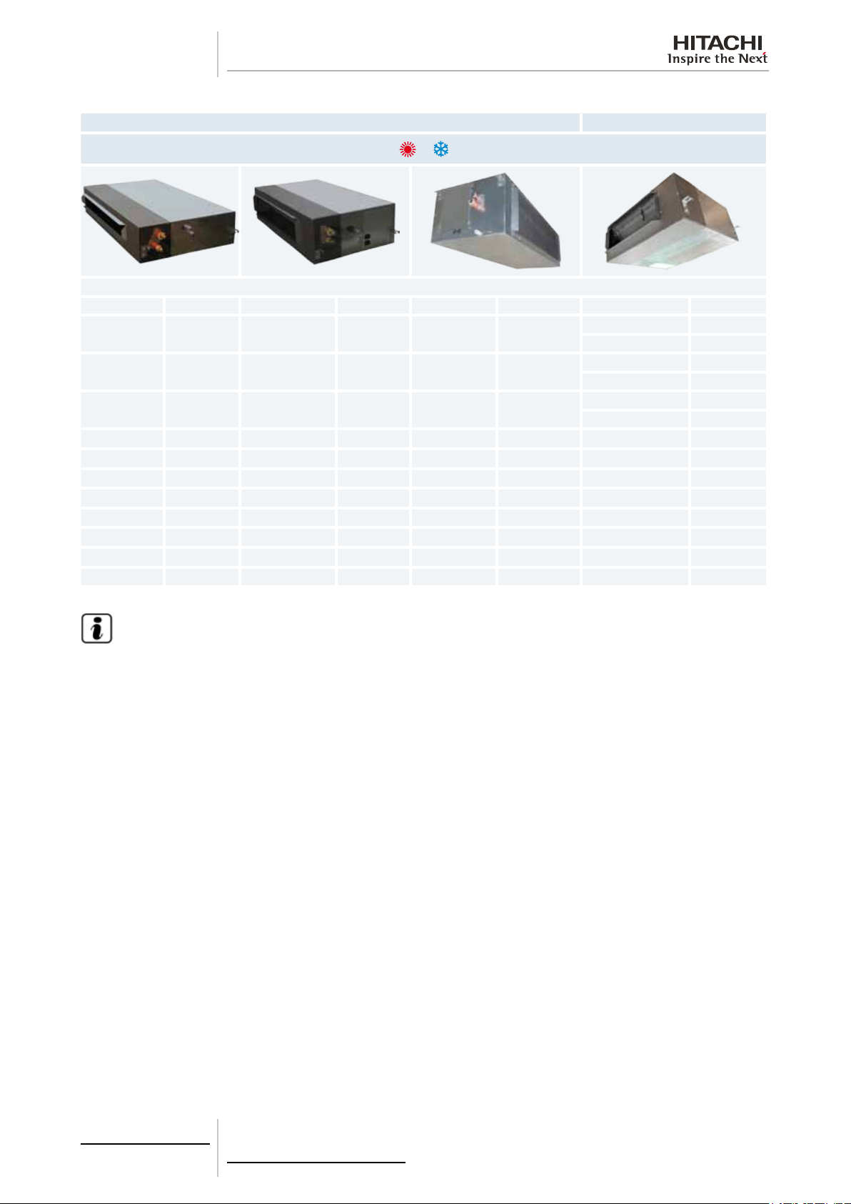
RPI RPIM
Indoor ducted unit
Unit Code Unit Code Unit Code Unit Code
RPI-0.8FSN4E 7E424013
RPI-1.0FSN4E 7E424014
RPI-1.5FSN4E 7E424015
RPI-2.0FSN4E
RPI-2.5FSN4E
RPI-3.0FSN4E
RPI-4.0FSN4E
RPI-5.0FSN4E
RPI-6.0FSN4E
(*)
(*)
(*)
(*)
(*)
(*)
7E424016
7E424017
7E424018
7E424020
7E424021
7E424022
RPI-8.0FSN3E 7E424010
RPI-10.0FSN3E 7E424011
RPIM-0.8FSN4E 7E430013
RPIM-0.8FSN4E-DU 7E431013
RPIM-1.0FSN4E 7E430014
RPIM-1.0FSN4E-DU 7E431014
RPIM-1.5FSN4E 7E430015
RPIM-1.5FSN4E-DU 7E431015
N O T E
(*): Series available from October 2012. Before this date indoor units FSN3E series are available
8
TCGB0068 rev.1 - 08/2012
Page 17
1 General information
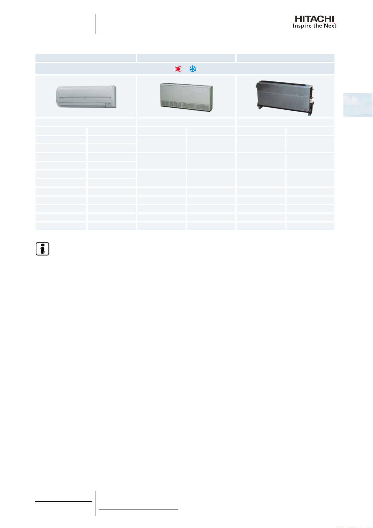
RPK RPF RPFI
Wall type Floor type Floor concealed type
Unit Code Unit Code Unit Code
RPK-0.8FSN3M (*) 60278146
RPK-0.8FSNH3M (*) 60278154
RPK-1.0FSN3M (*) 60278147
RPK-1.0FSNH3M (*) 60278155
RPK-1.5FSN3M (*) 60278148
RPK-1.5FSNH3M (*) 60278156
RPK-2.0FSN3M (*) 60278149 RPF-2.0FSN2E 7E450003 RPFI-2.0FSN2E 7E460003
RPK-2.5FSN3M (*) 60278150 RPF-2.5FSN2E 7E450004 RPFI-2.5FSN2E 7E460004
RPK-3.0FSN3M (*) 60278151
RPK-4.0FSN3M (*) 60278152
EV-1.5N (**) 60291612
RPF-1.0FSN2E 7E450001 RPFI-1.0FSN2E 7E460001
RPF-1.5FSN2E 7E450002 RPFI-1.5FSN2E 7E460002
1
N O T E
• (*): Series available from October 2012. Before this date indoor units FSN(H)2M series are available.
• (**): For RPK-(0.8-1.5)FSNH(2/3)M models only.
9
TCGB0068 rev.1 - 08/2012
Page 18
1 General information
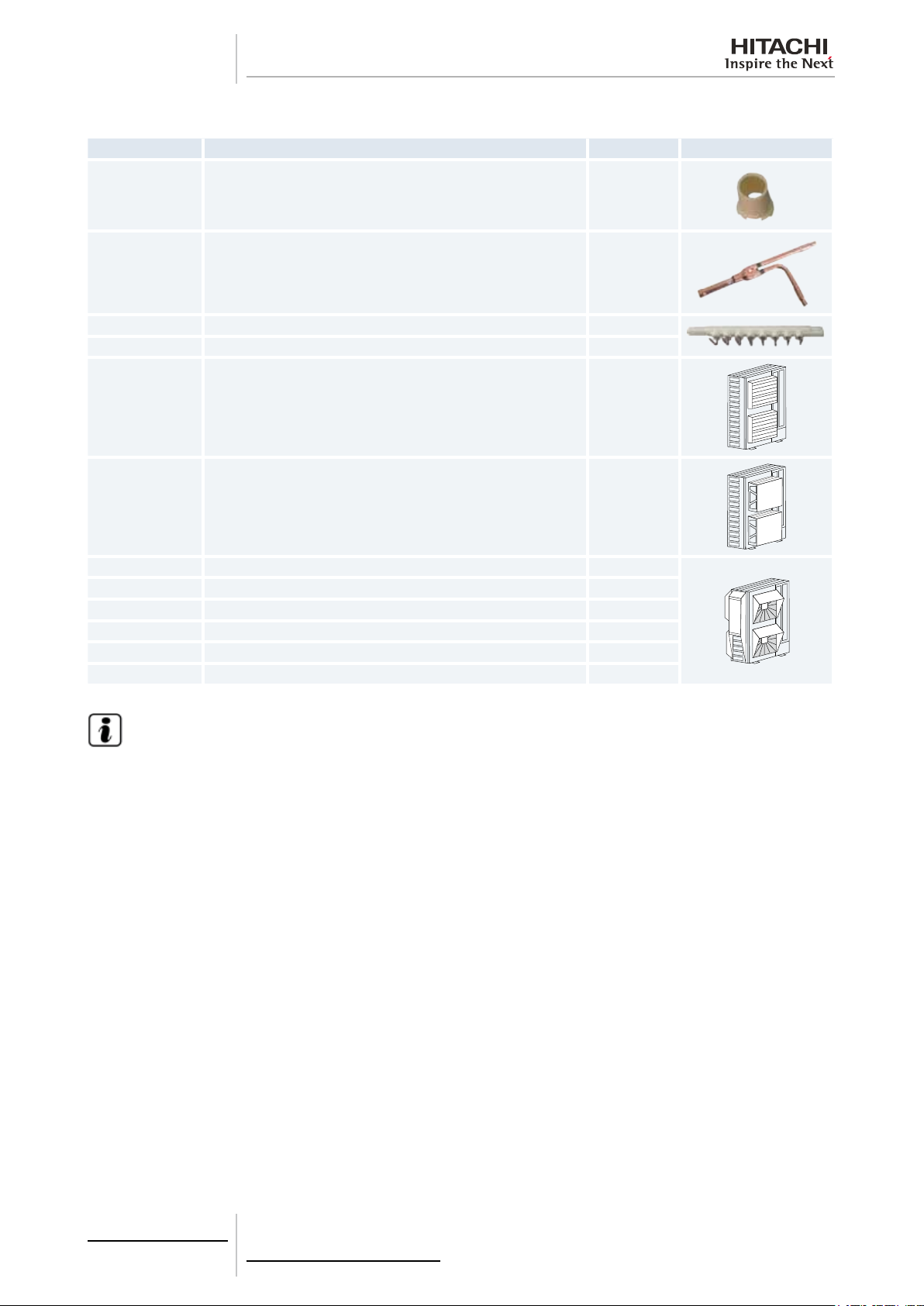
1.3.5 Accessory code list
Name Description Code Figure
DBS-26 Drain discharge connection 60299192
E-102SN2 Branch pipe kit (multikit) 70524001
MH-84AN Header branch (Distributor) 70522007
MH-108AN Header branch (Distributor) 70522008
AG-335A Air ow guide 60291431
WSP-335A Wind guard 60291432
ASG-NP335F Snow protection hood; air outlet (Zinc plate) 60291433
ASG-NP335FS2 Snow protection hood; air outlet (Stainless plate) -
ASG-NP280B Snow protection hood; air inlet of rear side (Zinc plate) -
ASG-NP280BS2 Snow protection hood; air inlet of rear side (Stainless plate) -
ASG-NP280L Snow protection hood; air inlet of left side (Zinc plate) -
ASG-NP280LS2 Snow protection hood; air inlet of left side (Stainless plate) -
N O T E
• HITACHI has a range of accessories and remote control systems that can be used with the SET-FREE mini
outdoor units. Please, refer to the Controls Technical Catalogue.
• HITACHI has also a range of accessories that can be used with the indoor units. Please, refer to the Indoor
Units Technical Catalogue.
10
TCGB0068 rev.1 - 08/2012
Page 19

2 Features and benets
F e a t u r e s a n d b e n e f i t s
2.
Index
2.1. Selection benets .................................................................................................................................. 12
2.1.1. Wide range of units, accessories and remote controls .............................................................................. 12
2.1.2. High number of connectable indoor units .................................................................................................. 14
2.1.3. Individual operation ................................................................................................................................... 15
2.1.4. Assisted air conditioning installation design by Hi-Tool kit selection software ........................................... 15
2.2. Installation benets................................................................................................................................16
2.2.1. Easy and exible unit installation ............................................................................................................... 16
2.2.2. Easy and exible electrical installation ...................................................................................................... 16
2.2.3. Easy and exible control connection (Central Station, BMS Interface, CS-NET WEB) ............................. 18
2.3. Start-up benets .................................................................................................................................... 19
2.3.1. Automatic start-up test ............................................................................................................................... 19
2.3.2. Service verication .................................................................................................................................... 20
2.4. Functionality benets.............................................................................................................................21
2.4.1. Expanded temperature range .................................................................................................................... 21
2.4.2. Wide capacity range .................................................................................................................................. 22
2.4.3. Increased maximum piping length ............................................................................................................. 22
2.4.4. Advanced technology ................................................................................................................................ 23
2.5. Maintenance benets ............................................................................................................................32
2
2.5.1. Minimum maintenance .............................................................................................................................. 32
2.5.2. Easy accessibility ...................................................................................................................................... 32
2.5.3. Alarm codes ............................................................................................................................................... 32
2.5.4. SMS alarm ................................................................................................................................................. 32
2.5.5. Availability of maintenance tools ............................................................................................................... 32
11
TCGB0068 rev.1 - 08/2012
Page 20
2 Features and benets
2.1 Selection benets
2.1.1 Wide range of units, accessories and remote controls
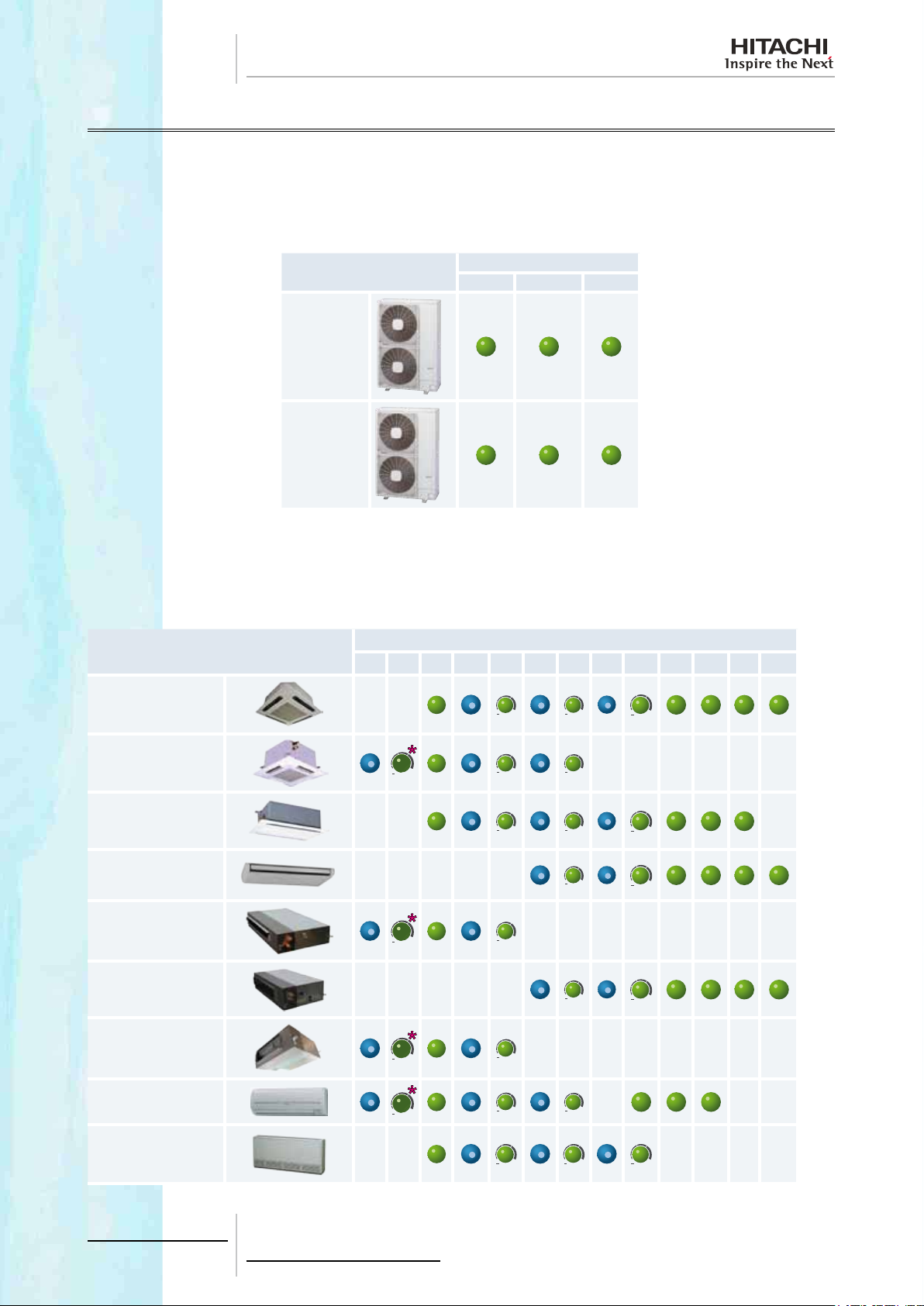
Outdoor unit
The SET-FREE mini series from HITACHI offers (3-6)HP range of outdoor units for being selected in single or three phase
combinations.
Capacity (HP)
4 5 6
Indoor unit
Model
FSVN2E
FSNY2E
The HITACHI indoor units to connect with this SET-FREE mini series have a wide range of capacities: from 0.8 to 6.0 HP.
The capacity of each indoor unit is exible: they are supplied set to the maximum capacity possible and can be easily adjusted to precise lower values in line with installation requirements.
Capacity (HP)
RCI 4-way cassette
Model
0.6 0.8 1.0 1.3 1.5 1.8 2.0 2.3 2.5 3.0 4.0 5.0 6.0
RCIM 4-way cassette
(compact)
RCD 2-way cassette
RPC ceiling type
RPI Indoor ducted unit
(low prole)
RPI Indoor ducted unit
RPIM Indoor ducted
unit
RPK wall type
RPF oor type
12
TCGB0068 rev.1 - 08/2012
Page 21
2 Features and benets
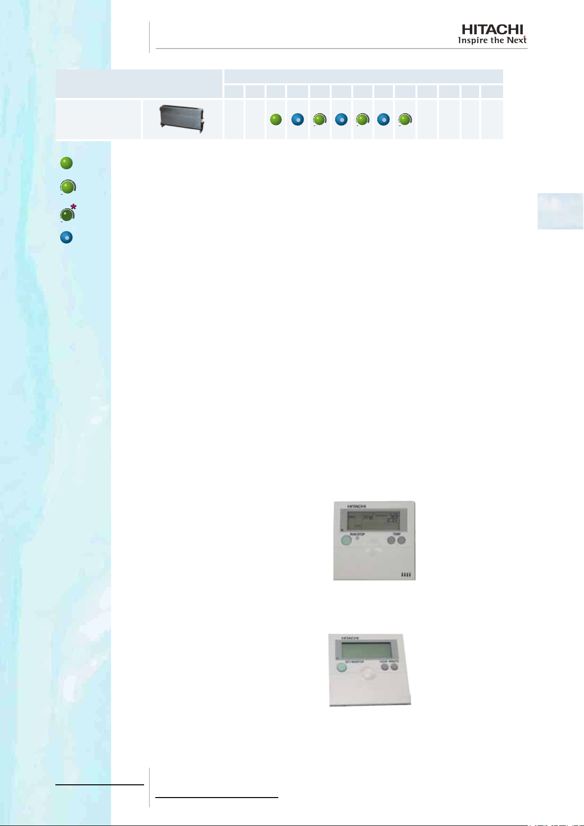
Model
RPFI oor concealed
type
Constant capacity unit.
Unit with a capacity that can be set to a lower margin using the DIP switch 3 setting for combinations with all
Set Free Series.
Unit of 0.8HP capacity that can be set to 0.6HP using specic DIP switch setting only for combinations with Set
Free Mini Series 2.
Capacity available with the DIP switch conguration.
Accessories
All the outdoor units have a range of accessories that facilitate installation, operation and maintenance.
These accessories are designed to adapt the unit to the type of installation that the air conditioning system requires and
improve its performance, always bearing in mind the quality parameters required.
The range of accessories includes:
• Remote controls, for handling and managing the operation of the installation.
• Multikits and distributors for pipe branches connection of indoor units.
• Drain discharge connection, to collect the draining.
• Air ow guide, wind guard and snow protection hood, to protect the outdoor unit fans and the air inlet/outlet.
0.6 0.8 1.0 1.3 1.5 1.8 2.0 2.3 2.5 3.0 4.0 5.0 6.0
Capacity (HP)
2
Remote controls
HITACHI has a range of remote control systems that are classied according to the type of management and the number
of units they manage:
• Individual remote control systems.
• Centralised remote control systems.
• Building air conditioning systems (CS-NET WEB).
• BMS (Building Management Systems).
Individual remote control systems
The individual remote control systems, whether they are wireless
or connected directly by cable, have a wide range of functions
for easier unit management, the programming of specic settings
or the identication of incidents. Recommended for managing a
small number of units.
Centralised remote control systems
The centralised remote control systems combine the functions of
the remote controls and extend the management and setting possibilities for several air conditioning systems distributed around the
entire oor of a building.
13
TCGB0068 rev.1 - 08/2012
Page 22
2 Features and benets
Computerised control systems
Computerised control systems increase management and setting
possibilities and allow this to be carried out from any point of the
local communication network, by means of a two-core non-polarity
cable or even using the Internet.
Recommended when you wish to independently manage more
than two plants in one building.
BMS (Building Management System)
Integration into installations with intelligent management. Gateway
interface with Lonworks, KNX, MODBUS and BACnet BMS systems.
2.1.2 High number of connectable indoor units
With SET-FREE FS(V)N(Y)2E system it is possible to connect one outdoor unit with up to 12 indoor units. Utilizing an
inverter control, a wide range of operation capacity control is also availabale. A maximum total combination horsepower
of 130% and a minimum total combination horsepower of 50% can be chosen by combination of the indoor units when
compared with the nominal outdoor unit capacity. Therefore, the system can meet individual air conditioning requirements
in most ofce buildings.
Indoor unit
Outdoor unit
RAS-4FS(V)N(Y)2E 2.0 4.0 5.2 1 8 0.6 (*)
RAS-5FS(V)N(Y)2E 2.5 5.0 6.5 1 10 0.6 (*)
RAS-6FS(V)N(Y)2E 3.0 6.0 7.8 1 12 0.6 (*)
Minimum nomi-
nal combination
capacity (HP)
Nominal
combination
capacity (HP)
Maximum nominal combination
capacity (HP)
Minimum combi-
nation quantity
of indoor units
Maximum com-
bination quantity
of indoor units
Minimum single operation
capacity (HP)
N O T E
• (*): Indoor unit of 0.8HP set as 0.6HP by specic DSW setting only for combinations with Set Free Mini Series 2.
• Please, refer to the chapter Piping work and refrigerant charge for the specic considerations.
14
TCGB0068 rev.1 - 08/2012
Page 23
2 Features and benets
2.1.3 Individual operation
SET-FREE mini series individual operation function allows to control the connected indoor units separately.
• In case of installing the indoors units in the same room, one
unit could continue operating -A- although the other one -Bstops by thermo-off, which means an energy saving and great
comfort.
A
B
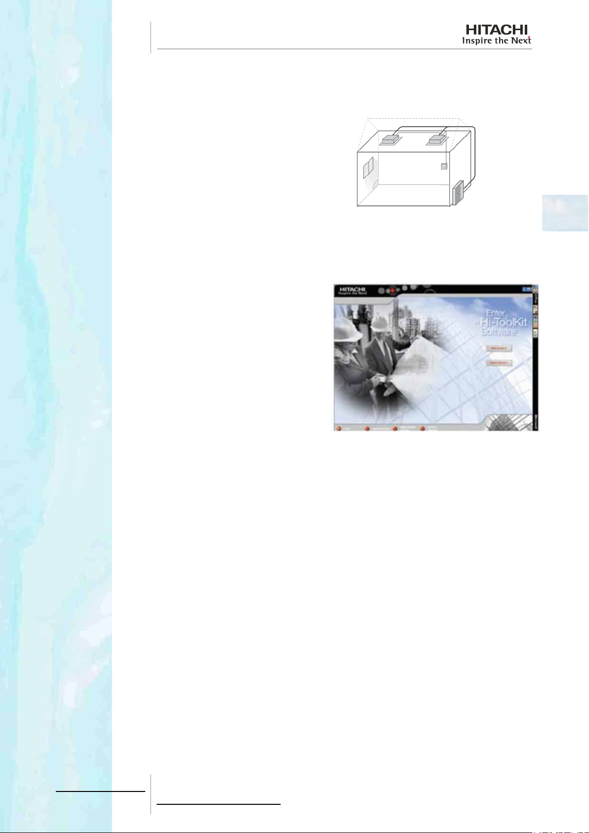
2.1.4 Assisted air conditioning installation design by Hi-Tool kit selection software
The Hi-Tool Kit selection software is a tool for designing HVAC
installations and automatically generating all necessary related information to complete the planned installation.
The necessary related information includes:
• Product selection table.
• Cooling and wiring diagram according to the installation design.
• Full list of necessary products to complete the installation.
• Installation start-up management.
2
15
TCGB0068 rev.1 - 08/2012
Page 24
2 Features and benets
2.2 Installation benets
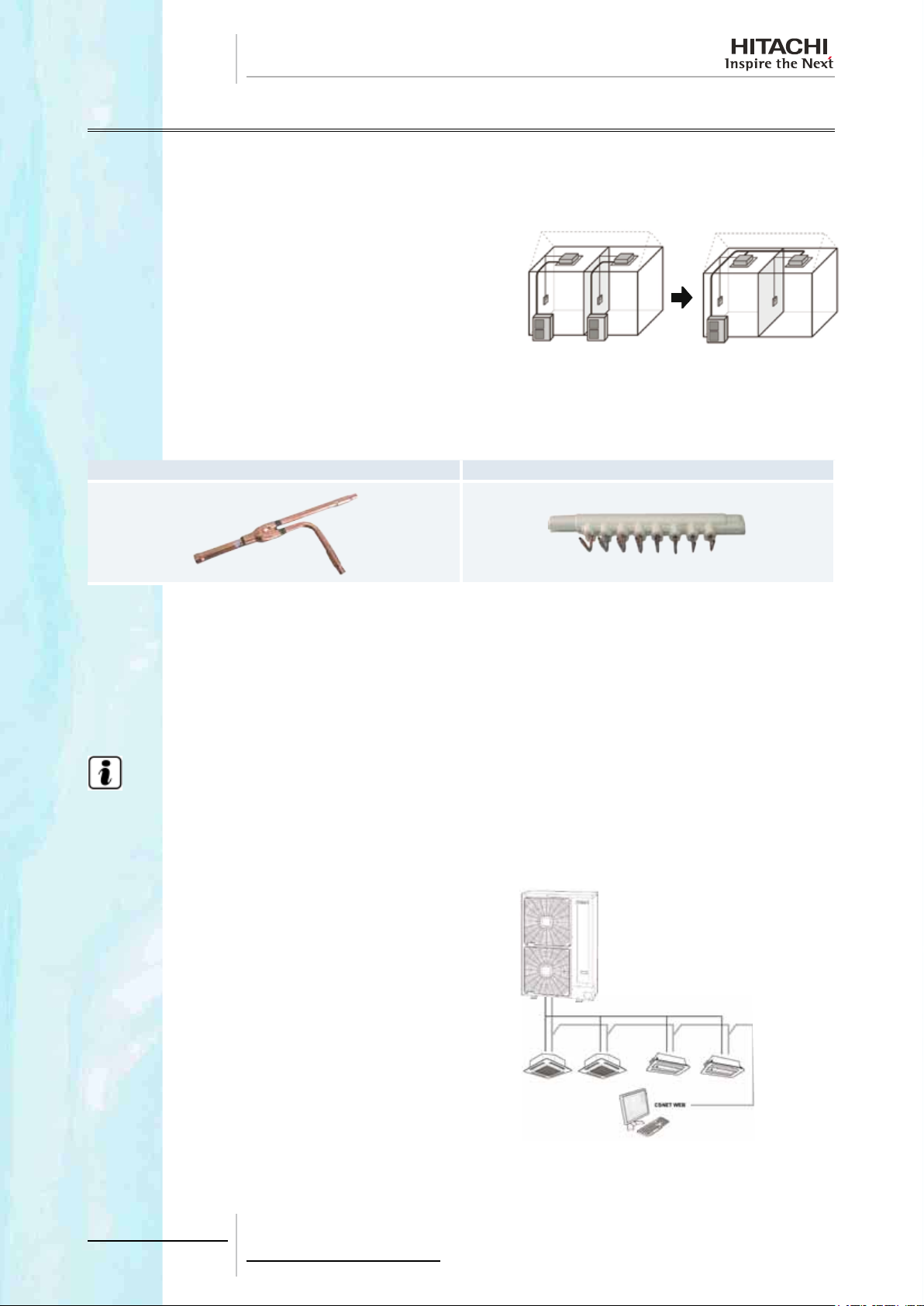
2.2.1 Easy and exible unit installation
Reduced installation space by individual operation
• For Indoor units installed in different rooms, the benets are:
- Outdoor installation space reduced to half.
- Decrease piping installation work and cost.
- Decrease wiring and power equipment.
A. Model without individual operation function.
B. FS(V)N(Y)2E model.
Different mounting accessories available
HITACHI provides all of the accessories required to connect the pipes (distributors and multikits). These accessories make
the installation process more exible and straightforward.
E-SN2 multikit MH-AN distributors
A B
2.2.2 Easy and exible electrical installation
Interconnection of units via H-LINK II
The units interconnect via a bus called H-LINK II, consisting of 2 non-polarity cables wich accept lengths of up to 1,000m.
Accessories are available if required to increase this length up to 5,000m (PSC-5HR).
N O T E
The control system, the indoor units and the remote control must be compatible with the H-LINK II bus.
Up to 160 units connected in a single H-LINK II bus line
It is possible to connect up to 160 indoor units from the SYSTEM
FREE range in a single H-LINK II bus line. To expand the installation or increase the bus lines available, simply add a new line.
All of the units are managed as one through the control systems
installed.
16
TCGB0068 rev.1 - 08/2012
Page 25
2 Features and benets
Specications
Transmission cable: 2-core
Transmission cable polarity: No polarity
Maximum number of outdoor units connected: 64 units per H-LINK II system
Maximum number of indoor units connected: 160 units per H-LINK II system
Maximum number of units: 200
Maximum wiring length: Total 1,000 m (including CSNET-WEB)
Recommended cable:
Voltage: 5 V DC
Shielded twisted pair cable or shielded pair cable over 0.75 mm
valent to KPEV-S)
2
(equi-
NOTE
• The DIP switches must be adjusted when the H-LINK II bus is used. If they are set incorrectly, a transmission
error may occur.
• The H-Link II system offers a high level of exibility for the design of air conditioning systems, due to its simple installation and the low total cost. Furthermore, centralised management is possible by connecting the
CSNET-WEB control system to the H-LINK II network cables.
• Additionally, using CSNET-WEB, it is possible to manage the installation over the internet.
2
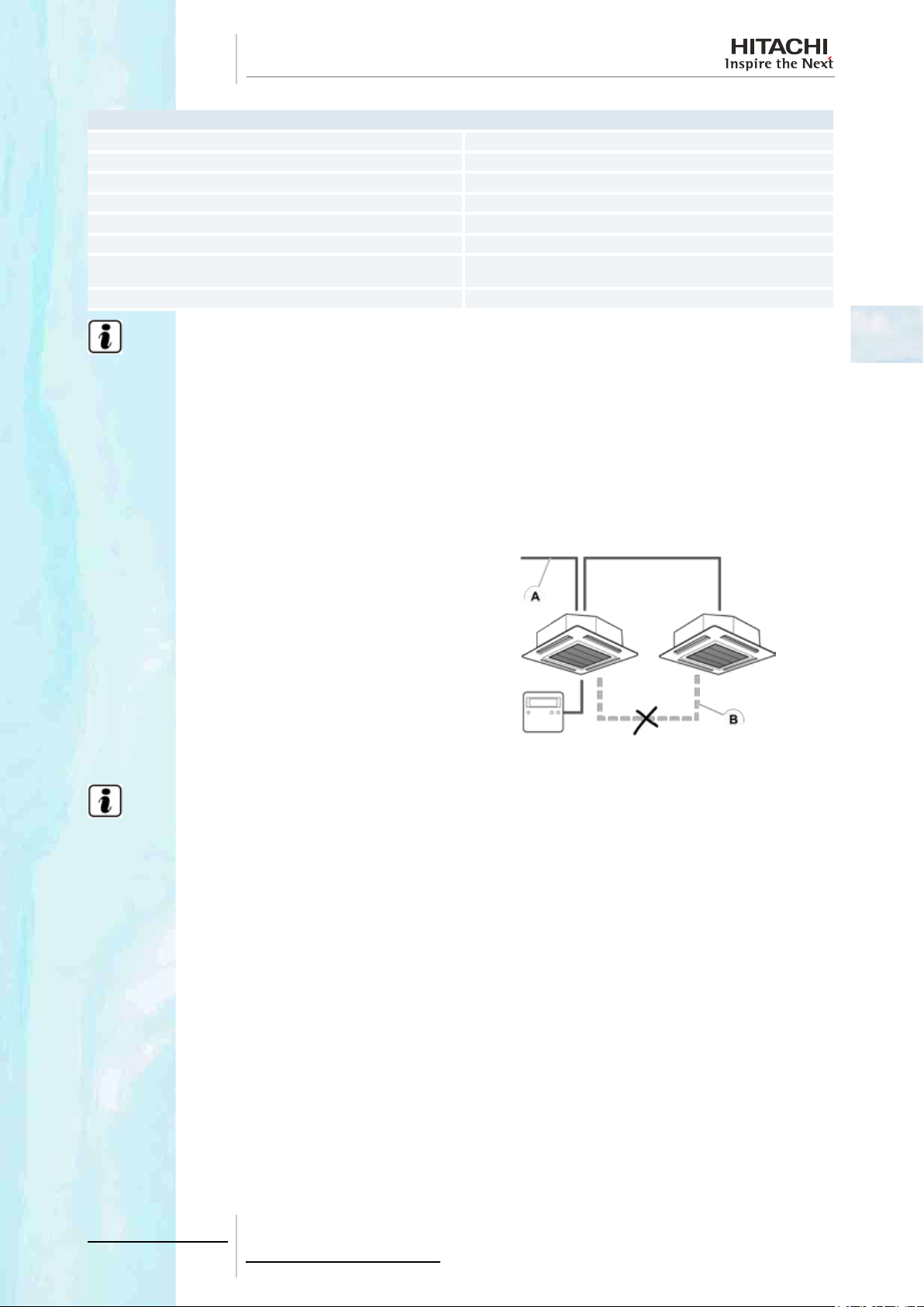
No operating cable for the remote control
In the case of multiple systems the indoor units can be controlled
using a single remote control switch without having to join them
with an operating cable for the remote control.
A. Operation wiring.
B. An operating cable is not required for using the remote control
switch.
N O T E
• When using the H-LINK II system, DIP switches have to be adjusted. If the DIP switches are not set or set incorrectly, an alarm may occur due to transmission failure. Total wiring length for the remote control switch can
be extended to up to 5,000 m. If total wiring length is less than 30 m, it is possible to use the normal wiring (0.3
mm²).
• The H-LINK II system provides maximum exibility for system design; installation is easy, and total costs are
reduced. Furthermore, it can be controlled centrally by connecting CS-NET WEB to H-LINK II wiring.
• You can also control the installation by Internet via CS-NET WEB.
17
TCGB0068 rev.1 - 08/2012
Page 26

2 Features and benets
2.2.3 Easy and exible control connection (Central Station, BMS Interface, CS-NET WEB)
Fast connection of new units
Extending the air conditioning system is now even easier. To add new units to the communication bus, it is only necessary
to connect the two bus cables to the communication terminals.
The new units that are added to the bus line are recognised by the control system and are congured automatically.
Auto-conguration of system units
The control systems for the air conditioning system are auto-congurable. In other words, they recognise the type of unit
to which they are connected, and the type of indoor unit and its capacity. The installation is started up more quickly and
efciently.
You can also congure all the units manually, so as to adjust the installation following customised parameters.
18
TCGB0068 rev.1 - 08/2012
Page 27
2 Features and benets
2.3 Start-up benets
2.3.1 Automatic start-up test
The installation is started up automatically, therefore considerably reducing the time required for the process.
There are the following types of start-up:
• Test run and identication of the units forming the system.
• Test run from the remote control.
• Test run from the outdoor unit.
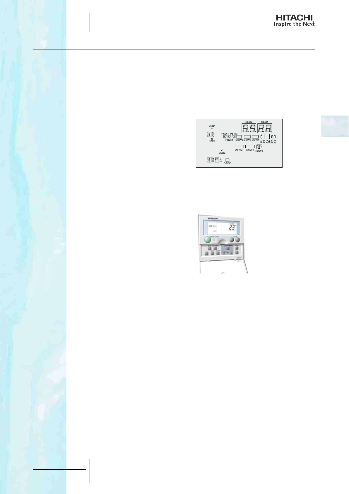
Test run and identication of the system units
The automatic test run can be activated through outdoor unit
DIP switch or indoor unit remote control switch. The outdoor unit
7-segment display gives all the information needed to check the
system is operating correctly.
The units forming part of the system are identied separately for
the outdoor and indoor units:
• Outdoor units: Using the remote control, the series to which
each of the operational outdoor unit belongs (for example, simple or multiple series) can be assigned.
• Indoor units: Using the rotary and DIP switch on each unit.
2
Test run from the remote control
The remote control can run 3 operations.
• Auto-diagnostic: quick check of the operating conditions of the
indoor units and the outdoor unit.
• Data memory query: if an abnormality occurs, the LCD remote
control switch shows an alarm code and saves all the operation settings of the unit at the time the fault occurs, so that a
quick diagnosis can be made of the installation.
• Optional function setting: the remote control switch allows cancellation of the 4-degree offset in the heating mode and an
increase in the fan speed setting, among 29 possible options.
This way, multiple indoor units can be set at the same time. Also, the conguration can easily be changed, even after the
installation has been completed.
Test run from the outdoor unit
The outdoor unit PCB is equipped with a 7-segment display, which depending on the position of the PSWs shows the
following parameters in sequence.
• Outdoor temperature.
• Discharge gas temperature.
• Evaporation temperature in heating mode.
• Condensing temperature.
• Discharge pressure.
• Compressor run time.
This allows quick and accurate diagnosis of the installation during normal operation or test run.
19
TCGB0068 rev.1 - 08/2012
Page 28

2 Features and benets
2.3.2 Service verication
System operation control
The working order of the system is continuously monitored through the control system. All operating parameters that the
system uses to manage the outdoor and indoor units are continuously supervised.
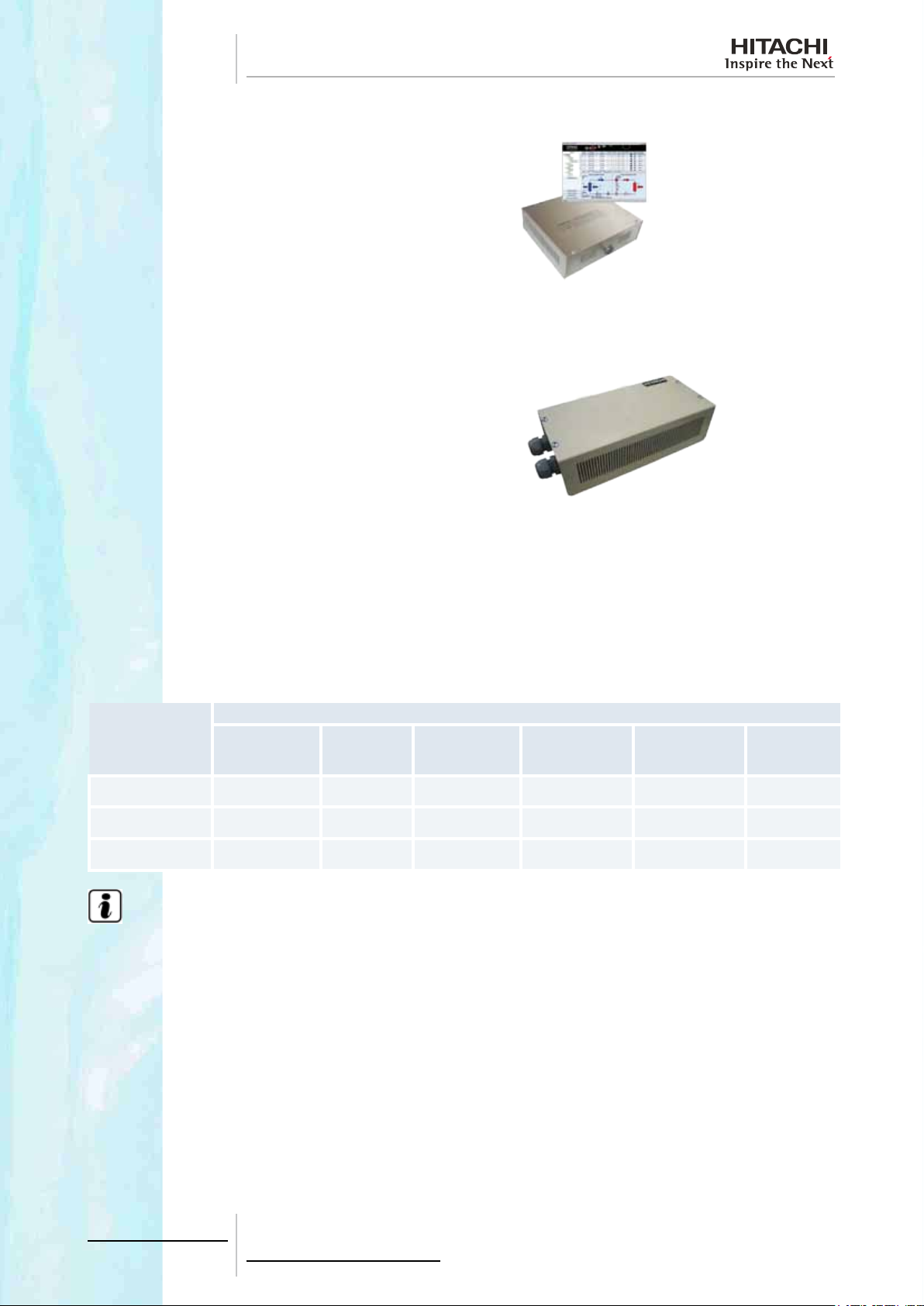
Assisted-management air conditioning system
The air conditioning system can be managed conveniently using
the assisted management software HITACHI Service Tools.
This software enables, for example, a laptop computer to be connected to the air conditioning system by means of an interface
connected to the H-LINK II bus. Using different menus, the software allows you to manage all the systems connected effectively
and obtain data to optimise system performance.
Compilation of operating data
All the data obtained using HITACHI Service Tools is compiled in different formats and monitored in various ways. The user
of the software can congure the data handling to monitor those parameters that are the most important in each installation.
The data reports allow you to verify the system operation continuously. Any deviation in the stipulated ranges of values are
detected immediately.
20
TCGB0068 rev.1 - 08/2012
Page 29
2 Features and benets
2.4 Functionality benets
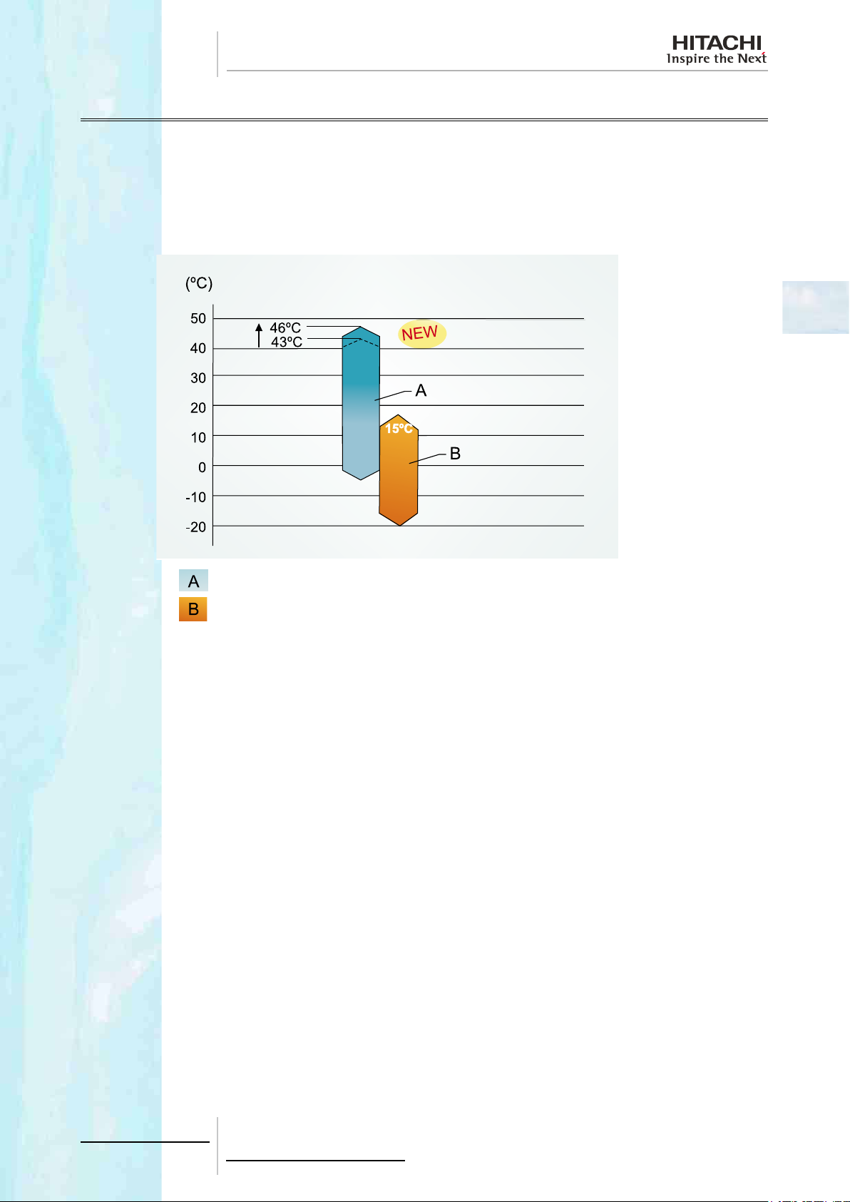
2.4.1 Expanded temperature range
FS(V)N(Y)2E series are able to work in a wide working range (from -5 to 46 ºC (DB) in cooling mode and from -20 to 15ºC
WB in heating mode).
The cooling working range has been increased up to 46ºC in outdoor ambient temperature respect previous model (43ºC).
2
-5ºC
-20ºC
Cooling (DB)
Heating (WB)
Fan regulation at low ambient temperature
• Wide working range thanks to fan control regulation, in cooling mode, for operating at low ambient temperature (down
to -5ºC DB).
• Fan control regulation enables working at low ambient temperature (down to -20ºC WB), in heating mode, reducing
“Defrost operations” or unit “stoppages” compared with conventional units.
21
TCGB0068 rev.1 - 08/2012
Page 30
2 Features and benets
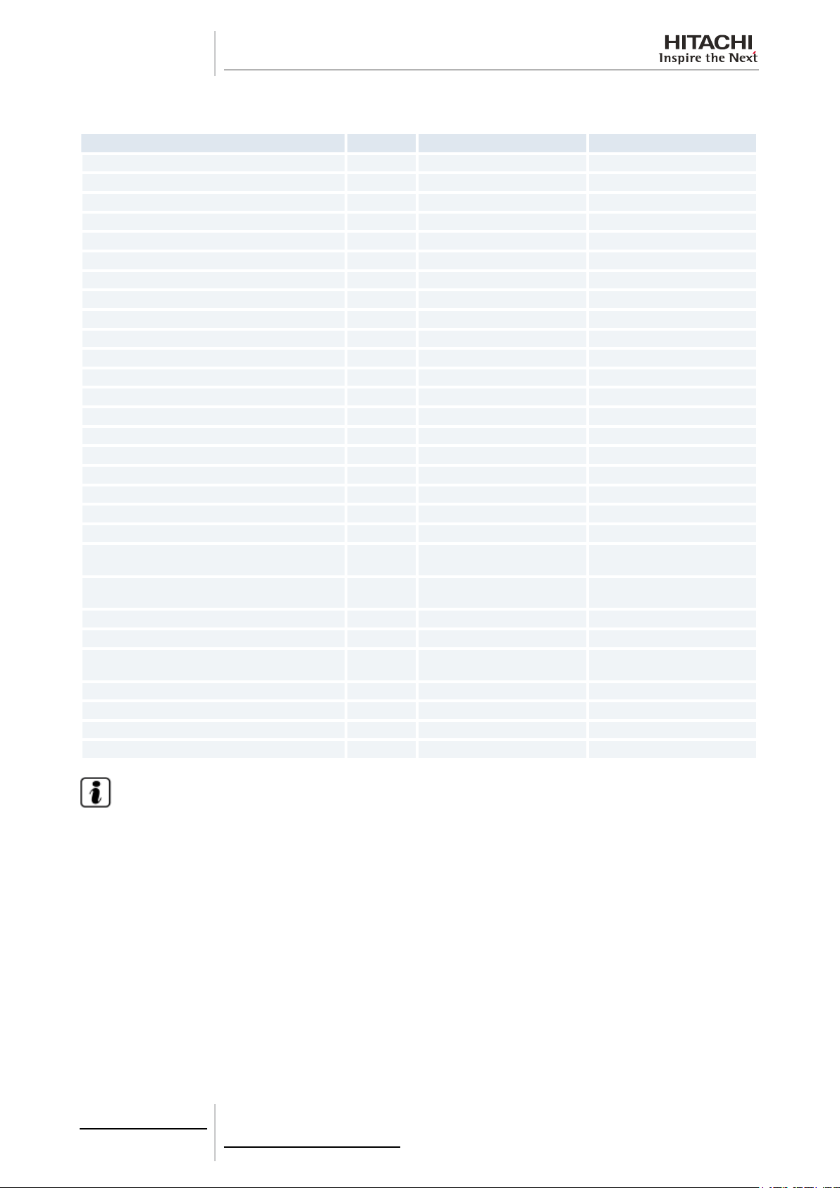
2.4.2 Wide capacity range
The control frequency system allows a wide capacity application range as shown below:
• Cooling capacity range at conditions: Indoor air inlet: 27/19 ºC (DB/WB); Outdoor air inlet: 35 ºC DB
4 kW
RAS-4FS(V)N(Y)2E
6 kW 8 kW 10 kW 12 kW 14 kW 16 kW
18 kW
4 kW
RAS-5FS(V)N(Y)2E
4 kW
RAS-6FS(V)N(Y)2E
6 kW 8 kW 10 kW 12 kW 14 kW 16 kW
6 kW 8 kW 10 kW 12 kW 14 kW 16 kW
• Heating capacity range at conditions: Indoor air inlet: 20 ºC DB; Outdoor air inlet: 7/6 ºC (DB/WB)
4 kW
RAS-4FS(V)N(Y)2E
4 kW
RAS-5FS(V)N(Y)2E
4 kW
RAS-6FS(V)N(Y)2E
6 kW 8 kW 10 kW 12 kW 14 kW 16 kW
6 kW 8 kW 10 kW 12 kW 14 kW 16 kW
6 kW 8 kW 10 kW 12 kW 14 kW 16 kW
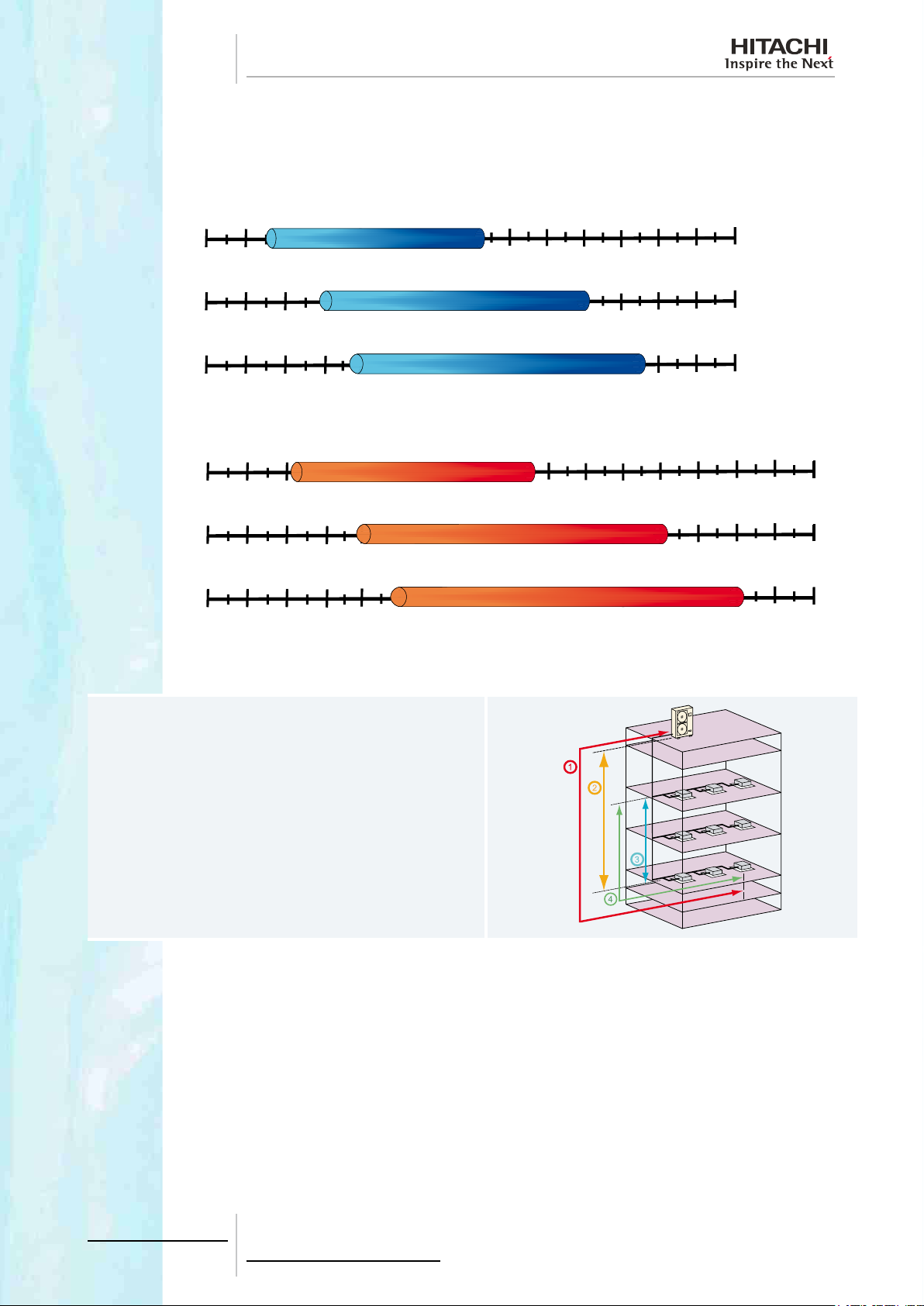
2.4.3 Increased maximum piping length
The maximum total piping length is 125m for 4HP and
135m for 5~6HP;
18 kW
18 kW
18 kW
18 kW
18 kW
20 kW
20 kW
20 kW
① Actual Maximum piping length is 75m.
② Height difference between indoor and outdoor units is
30m.
③ Height difference between indoor units is 15m.
④ Piping length from the first multi-kit to the farthest
indoor unit is 40m.
22
TCGB0068 rev.1 - 08/2012
Page 31

2 Features and benets
O
P
2.4.4 Advanced technology
The functionality benets explained before (Highly efciency system, wide capacity range and expanded working range)
are direct consequence of the advanced technology applied on all the system components.
Then, the main features on different components of the system will be detailed:
2
Refrigerant ow for cooling Refrigerant ow for heating
A: Super high-stream fan. N: Highly efcient scroll compressor.
B: Side-ow technology. O: Two stage oil separator technology.
C: Silent fan unit. P: Reduced power consumption.
D: DC fan motor with outstanding efciency. Q: High pressure shell.
E: Outdoor unit heat exchanger. R: Lubrication.
F: Outdoor unit expansion valve. S: Protection against liquid return.
G: Sub-cooling circuit. T: Efcient design of stator coils.
H: Reversing valve. U: DC compressor with neodymium magnet.
I: Improved performance by sub-cooling circuit. V: Low noise.
J: Gas by-pass. W: Stop valve of the liquid pipe.
K: Compressor. X: Indoor unit expansion valve.
L: Accumulator. Y: Indoor unit heat exchanger.
M: Stop valve of the gas pipe. Z: Oil separator
AA: Check valve
23
TCGB0068 rev.1 - 08/2012
Page 32

2 Features and benets
Heat exchanger
Improved performance by subcooling circuit
The system performance is improved by enlarged heat transfer area of FS(V)N(Y)2E unit and subcooler heat exchanger.
A: Rear side.
B: Front side.
C: Sub-cooler.
D: Air inlet.
E: Air outlet.
F: Increase of enthalpy due to the use of the sub-cooling circuit.
Fan unit
Super high-stream fan
The outdoor units have been designed with a new super high-stream fan of Ø544 mm, reducing the sound level and increasing its reliability, by the use of a three-blade design propeller.
This fan is much more aerodynamic than earlier models. It has a greater surface area in contact with the air and a better
turning angle, preventing turbulence and allowing the ventilator to be tted lower.
Additionally, the rib structure synchronized with rotation ow from the fan reduces the air resistance at the air outlet grille.
A: Optimized distribution at air outlet angle.
B: Optimized distribution at air inlet angle.
C: Increased angular advance.
Side ow technology
Energy-saving and uniform air velocity distribution by side ow technology.
A: Air inlet.
B: Air outlet.
C: Air speed (m/s).
B
A
C
24
TCGB0068 rev.1 - 08/2012
Page 33

2 Features and benets
Silent fan unit
Low noise due to the following aspects:
• Combination of the three-blade and slim fan: The fan has been designed to have a lower body than traditional fans, and
achieves surprising results, with a noise reduction of up to 4dB (A).
15%
A
A: Conventional fan.
B: FS(V)N(Y)2E fan.
• DC fan motor: The smooth rotating fan motor with low vibration reduces the noise generation.
DC fan motor with outstanding efciency
The DC fan motor greatly improves efciency compared to conventional products with AC motors. In addition, air blasts are
reduced by controlling the rotation speed of the fan. Stable operation is provided against strong head winds of approximately 10 m/s on the front face of the outdoor unit.
a: Motor efciency (%).
b: Revolutions per Min. (rpm).
A: DC motor.
B: AC motor.
C: Efciency increased by 40% (motor power consumption halved).
B
A
C
a
B
2
b
25
TCGB0068 rev.1 - 08/2012
Page 34

2 Features and benets
HITACHI exclusive scroll compressor
Highly efcient scroll compressor
The HITACHI DC INVERTER scroll compressor has been developed to increase efciency, reliability and to reduce power
input:
- High performance at intermediate season.
- High efciency at low speed (release valve and compacted winding of the DC-inverter motor).
A: New drive mechanism, oil feeding mechanism etc,... H: Oil return pipe.
B: Newly developed scroll for R410A. I: Asymmetric scroll lap.
C: DC-Inverter motor (compacted winding). J: Shut out.
D: Sub-bearing. K: High performance.
E: High reliability. L: Decrease of intake loss.
F: Decreased of bearing load. M: Decrease of leak loss.
G: Minimizing of shaft swing. N: Increase of superheat loss.
Two stage oil separator technology
The rst oil separating should be done for SET FREE mini machine adopting the Hitachi special compressor having the
high-efcient oil separating function. At the same time, the second oil separating can be achieved through equipping the
oil separator on the discharge pipeline, so the oil separating effect ensures the system operation more stable and reliable.
Refrigerant gas
with a little oil
Oil separator
Second stage
oil separating
Heat loss is greatly
reduced
Mechanical loss is
Gas suction
greatly reduced
26
TCGB0068 rev.1 - 08/2012
First stage oil
separating
Compressor
Refrigerant gas with minimum oil
Page 35

2 Features and benets
Reduced power consumption
• Highly efcient DC Scroll Compressor (use of neodymium magnets in the compressor motor rotor).
• New inverter control.
• Self demand control: Auto-control of power consumption, which can be regulated from 100%, 70% and 50% of nominal
value. Avoids excess energy consumption by regulating the frequency.
Auto-control of power consumption.
This function maintains the set current value.
Set current value
Electrical
consumption
Morning
Day
Night
This current value can be
chosen from 50%, 70%
or 100% of the nominal
value
• Wave mode: Regulation of demand through wave control. The demand is regulated by controlling the wave.
Power consumption auto-control
Energy
consumption
Without energy value control
Average energy consumption
Energy value set
Energy
consumption
Time
(min)
Energy value auto control
Average energy consumption
Energy value set
Time
(min)
High pressure shell
• It acts as an oil separator reducing the amount of oil circulating in the cooling system giving better heat exchanger
efciency.
• Motor heat is not added to the suction gas before compression, which reduces the discharge gas temperature. This is
particularly important at low suction temperatures. The discharge gas cools the motor sufciently.
• Refrigerant cannot enter the shell during the off cycle causing oil dilution and oil foaming at start up.
• New system of regulating pressure, increasing the compressor’s efciency and reliability in part load mode. This system ensures the work pressure of the compressor is always at optimum level regardless of the charge, so that the ratio
between the discharge pressure (Pd) and the suction pressure (Ps) is optimum as in the following graphic:
2
27
TCGB0068 rev.1 - 08/2012
Overcompression
zone which removes
the new pressure
regulation system
Pressure
Volume
Page 36

2 Features and benets
Lubrication
Bearing in mind that lubrication is one of the most important factors in the service life of a compressor, HITACHI has developed a system based on the pressure differences between the suction and discharge using a secondary pump at the base
of the compressor. As a result, all of the compressor’s moving parts are lubricated evenly, ensuring high reliability in terms
of its operating range, even at low frequencies.
A: Suction.
B: Discharge.
C: Roller bearing.
D: Synchronous motor.
E: Asymmetric scroll.
F: Oil return pipe.
G: Sub-ball-bearing structure.
H: Trochoid oil pump.
Protection against liquid return
When the compressor is at rest, the moving scroll rests on the casing. When the compressor starts to run, the pressure in
the chamber under the scroll builds up through two bleed holes in the medium pressure section of the compression stroke.
This pressure then forces the scroll up against the housing and seals the compression chamber. If liquid returns to the
compressor, the resulting increase in pressure forces the scroll downwards, breaking the seal and allowing the liquid to
pass back into the compressor body, where it will boil off due to the higher temperature.
A: Suction inlet.
B: Gas outlet.
C: Fixed scroll.
D: Moving scroll.
E: Housing.
F: Medium pressure chamber.
G: “Oldham ring”
H: Shaft.
I: Oilway.
Efcient design of stator coils
The new design of the stator coils positioned to optimize the magnetic eld signicantly reduce heat losses, and increase
the motor’s efciency at low speeds.
Compressor
efency
28
TCGB0068 rev.1 - 08/2012
New stator
coil design
Current model
rpm
Page 37

2 Features and benets
DC compressor with neodynium magnet
The use of a DC compressor with neodynium magnets in the rotor improves the performance at around the 30-40 Hz range
where the operation time of the inverter compressor is longest. Additionally, to suppress electromagnetic noise interference
and achieve low noise, the rotor has been divided into two parts and the electric pole displaced.
Characteristics at low speed, which affect the annual running cost, have been signicantly improved.
High efciency
motor (%)
DC Motor
Rotor shape optimized
Neodymium magnet
95
AC Motor
Reduction of the
typical electromagnetic noise of the
DC compressor
Increased efciency in the
complete range
of rpms used
0
2,000 4,000 6,000
rpm
Low noise
• Inverter control: The inverter controls compressor speeds from 30 Hz to 115 Hz, quickly reaching the set temperature
and maintaining a stable energy-saving operation, thus reducing the noise since the compressor is not running continuously.
Setting temperature (in heating mode)
Setting temperature
Temperature
of the room
Compressor rotor
DC Inverter
Machine with
constant speed
2
Time
- In the case of UTOPIA series: Quickly reaches the temperature set at high power, then maintains stable energysaving operation.
- In the case of other constant speed machines: Slowly reaches the set temperature, then turns on and off repeatedly
to maintain the temperature, operating uneconomically and wasting energy.
Power consumption (in heating mode)
High power operation
Compressor
(rpm)
Energy saving operation
Machine with
constant speed
DC Inverter
Time
- In case of existing machines with constant speed, repeated turning on and off wastes energy.
29
TCGB0068 rev.1 - 08/2012
Page 38

2 Features and benets
• Optimized rotor shape: The scroll compressor allows reduced noise and vibration levels due to:
- The compression points are evenly distributed along the compression stroke.
- The reduced number of components used.
- Use of a high-pressure insulation shell.
Optimized rotor shape
Compressor rotor
For compressor motor,
before changing the rotor
Noise
Frequency (Hz)
Electromagnetic noise reduced
For compressor motor, after
changing the rotor
Noise
Frequency (Hz)
• Acoustically insulated compressor: The scroll compressor is insulated by means of a acoustic cover, providing minimum noise levels.
30
TCGB0068 rev.1 - 08/2012
Page 39

2 Features and benets
Large range of operating possibilities
The use of these machines together with CSNET-WEB can increase the performance of these installations even more by:
• Scheduled programming, which prevents these machines from running continuously in rooms which are not being used, and allows rooms to be preheated
or pre-refrigerated just before being occupied.
• Limiting the set temperatures, which means that machines do not work at maximum capacity when comfort does not require it.
• Locking functions from the central control, thus avoiding incorrect or ineffective
use of the units.
All these and many more functions mean that the use of the installation as a whole
can be optimized. And it is worth remembering that because of the wide range of
indoor units you can always nd the unit with the power and type of installation
that best suits your needs. CS-NET-WEB Ability to lock functions from the central
control.
2
31
TCGB0068 rev.1 - 08/2012
Page 40

2 Features and benets
2.5 Maintenance benets
2.5.1 Minimum maintenance
The units have been designed in line with Hitachi’s philosophy, guaranteeing great reliability and robustness and reducing
maintenance to a minimum.
2.5.2 Easy accessibility
The system components are easily accessible. You can access all of the unit’s components to perform any necessary operations through a simple cover. The entire system is designed for maintenance operations to be easy and simple.
2.5.3 Alarm codes
The alarms are grouped by elements within the system in order to
facilitate maintenance work and optimize the tter’s job.
2.5.4 SMS alarm
The alarm signals can also be received through a simple SMS
specifying the cycle affected and the alarm code, allowing incidents to be detected and solved more quickly.
2.5.5 Availability of maintenance tools
All the functions of the Hitachi Service Tools for setup are applicable to unit maintenance, both preventive and corrective, so that
any problem can be detected and solved immediately.
CSNET-WEB is also useful for maintenance tasks.
32
TCGB0068 rev.1 - 08/2012
Page 41

3 General data
G e n e r a l d a t a
3.
Index
3.1. General data..........................................................................................................................................34
3.1.1. General conditions ..................................................................................................................................... 34
3.1.2. RAS-4FS(V)N(Y)2E ................................................................................................................................... 35
3.1.3. RAS-5FS(V)N(Y)2E ................................................................................................................................... 36
3.1.4. RAS-6FS(V)N(Y)2E ................................................................................................................................... 37
3.2. Component data ....................................................................................................................................38
3.2.1. RAS-(4-6)FSVN2E .................................................................................................................................... 38
3.2.2. RAS-(4-6)FSNY2E .................................................................................................................................... 38
3.2.3. Compressors ............................................................................................................................................. 39
3
3.3. Electrical data .......................................................................................................................................40
3.3.1. Considerations ........................................................................................................................................... 40
3.3.2. RAS-(4-6)FS(V)N(Y)2E ........................................................................................................................... 40
33
TCGB0068 rev.1 - 08/2012
Page 42

3 General data
3.1 General data
3.1.1 General conditions
1 The heating and cooling capacities indicated refer to the outdoor unit operating with the indoor units at 100% of their
capacity, and are based on Standard EN14511.
Operating conditions Cooling Heating
Indoor air inlet temperature
Outdoor air inlet temperature
DB: dry bulb; WB: wet bulb.
Pipe length: 7.5 m; pipe height: 0 m
2 The sound pressure level was measured in an anechoic chamber, so reected sound should be taken into considera-
tion when installing the unit. Test were carried out under the following conditions.
a. Measurement point located: 1 m from the surface of the unit’s service cover and 1.5 m from oor level.
b. Units working with their nominal power supply.
DB 27.0 °C 20.0 °C
WB 19.0 °C —
DB 35.0 °C 7.0 °C
WB — 6.0 °C
3 The ERR and COP have been calculated with outdoor input power only.
34
TCGB0068 rev.1 - 08/2012
Page 43

3 General data
3.1.2 RAS-4FS(V)N(Y)2E
Item Units RAS-4FSVN2E RAS-4FSNY2E
Minimum - Maximum indoor units connectable - 1 - 8 (*1) 1 - 8 (*1)
Minimum - Maximum connected capacity % 50 - 130 50 - 130
Nominal cooling capacity (min - max) kW 11.2 (5.60 - 11.2) 11.2 (5.60 - 11.2)
Nominal heating capacity (min - max) kW 12.5 (6.30 - 12.5) 12.5 (6.30 - 12.5)
Nominal cooling power input kW 2.75 2.72
Nominal heating power input kW 3.03 3.00
EER / COP (*2) - 4.07 / 4.13 4.12 / 4.17
Energy class (cooling / heating) - A / A A / A
Noise level cooling (sound pressure) (night mode) dB(A) 49 (45) 49 (45)
Noise level heating (sound pressure) dB(A) 51 51
Air ow (cooling / heating) m
Dimensions (H x W x D) mm 1380 / 950 / 370 1380 / 950 / 370
Net weight kg 100 102
Gross weight kg 113 115
Power supply - 1~ 230V 50Hz 3N~ 400V 50Hz
Recommended fuse size A 32 20
Starting current A Less than maximum current Less than maximum current
Maximum current A 26 13
Running current cooling A 12.2 4.1
Running current heating A 13.4 4.6
Power cable size (according to EN 60335-1)
Transmitting cable size between indoor unit and
outdoor unit
Piping diameter (liquid / gas) mm (inch) Ø9.53 (3/8) / Ø15.88 (5/8) Ø9.53 (3/8) / Ø15.88 (5/8)
Refrigerant charge before shipment kg 3.6 3.6
Maximum piping length (additional refrigerant
charge needed)
Height difference (O.U. higher / O.U. lower) m 30 / 30 30 / 30
Working range (cooling // heating) °C -5 / +46 (DB) // -20 / +15(WB) -5 / +46 (DB) // -20 / +15(WB)
Refrigerant - R410A R410A
Compressor type - Scroll DC Inverter driven Scroll DC Inverter driven
3
/min 90 / 90 90 / 90
quantity x
mm²
quantity x
mm²
m (g/m) 75 (need to be calculated) 75 (need to be calculated)
3 x 6.0 5 x 4.0
2 x 0.75 2 x 0.75
3
N O T E
• (*1): Please, refer to the chapter Piping work and refrigerant charge for the specic considerations.
• (*2) Calculated with outdoor input only.
35
TCGB0068 rev.1 - 08/2012
Page 44
3 General data
3.1.3 RAS-5FS(V)N(Y)2E
Item Units RAS-5FSVN2E RAS-5FSNY2E
Minimum - Maximum indoor units connectable - 1 - 10 (*1) 1 - 10 (*1)
Minimum - Maximum connected capacity % 50 - 130 50 - 130
Nominal cooling capacity (min - max) kW 14.0 (7.00 - 14.0) 14.0 (7.00 - 14.0)
Nominal heating capacity (min - max) kW 16.0 (8.00 - 16.0) 16.0 (8.00 - 16.0)
Nominal cooling power input kW 3.88 3.84
Nominal heating power input kW 4.20 4.16
EER / COP (*2) - 3.61 / 3.81 3.65 / 3.85
Energy class (cooling / heating) - A / A A / A
Noise level cooling (sound pressure) (night mode) dB(A) 51 (47) 51 (47)
Noise level heating (sound pressure) dB(A) 53 53
Air ow (cooling / heating) m
Dimensions (H x W x D) mm 1380 / 950 / 370 1380 / 950 / 370
Net weight kg 100 102
Gross weight kg 113 115
Power supply - 1~ 230V 50Hz 3N~ 400V 50Hz
Recommended fuse size A 32 20
Starting current A Less than maximum current Less than maximum current
Maximum current A 26 13
Running current cooling A 17.2 5.8
Running current heating A 18.6 6.3
Power cable size (according to EN 60335-1)
Transmitting cable size between indoor unit and
outdoor unit
Piping diameter (liquid / gas) mm (inch) Ø9.53 (3/8) / Ø15.88 (5/8) Ø9.53 (3/8) / Ø15.88 (5/8)
Refrigerant charge before shipment kg 3.6 3.6
Maximum piping length (additional refrigerant
charge needed)
Height difference (O.U. higher / O.U. lower) m 30 / 30 30 / 30
Working range (cooling // heating) °C -5 / +46 (DB) // -20 / +15(WB) -5 / +46 (DB) // -20 / +15(WB)
Refrigerant - R410A R410A
Compressor type - Scroll DC Inverter driven Scroll DC Inverter driven
3
/min 90 / 90 90 / 90
quantity x
mm²
quantity x
mm²
m (g/m) 75 (need to be calculated) 75 (need to be calculated)
3 x 6.0 5 x 4.0
2 x 0.75 2 x 0.75
N O T E
• (*1): Please, refer to the chapter Piping work and refrigerant charge for the specic considerations.
• (*2) Calculated with outdoor input only.
36
TCGB0068 rev.1 - 08/2012
Page 45

3 General data
3.1.4 RAS-6FS(V)N(Y)2E
Item Units RAS-6FSVN2E RAS-6FSNY2E
Minimum - Maximum indoor units connectable - 1 - 12 (*1) 1 - 12 (*1)
Minimum - Maximum connected capacity % 50 - 130 50 - 130
Nominal cooling capacity (min - max) kW 15.5 (7.80 - 15.5) 15.5 (7.80 - 15.5)
Nominal heating capacity (min - max) kW 18.0 (9.00 - 18.0) 18.0 (9.00 - 18.0)
Nominal cooling power input kW 4.67 4.62
Nominal heating power input kW 4.90 4.85
EER / COP (*2) - 3.32 / 3.67 3.35 / 3.71
Energy class (cooling / heating) - A / A A / A
Noise level cooling (sound pressure) (night mode) dB(A) 51 (48) 51 (48)
Noise level heating (sound pressure) dB(A) 53 53
Air ow (cooling / heating) m
Dimensions (H x W x D) mm 1380 / 950 / 370 1380 / 950 / 370
Net weight kg 100 102
Gross weight kg 113 115
Power supply - 1~ 230V 50Hz 3N~ 400V 50Hz
Recommended fuse size A 32 20
Starting current A Less than maximum current Less than maximum current
Maximum current A 26 13
Running current cooling A 20.7 7.0
Running current heating A 21.7 7.4
Power cable size (according to EN 60335-1)
Transmitting cable size between indoor unit and
outdoor unit
Piping diameter (liquid / gas) mm (inch) Ø9.53 (3/8) / Ø15.88 (5/8) Ø9.53 (3/8) / Ø15.88 (5/8)
Refrigerant charge before shipment kg 3.6 3.6
Maximum piping length (additional refrigerant
charge needed)
Height difference (O.U. higher / O.U. lower) m 30 / 30 30 / 30
Working range (cooling // heating) °C -5 / +46 (DB) // -20 / +15(WB) -5 / +46 (DB) // -20 / +15(WB)
Refrigerant - R410A R410A
Compressor type - Scroll DC Inverter driven Scroll DC Inverter driven
3
/min 100 / 100 100 / 100
quantity x
mm²
quantity x
mm²
m (g/m) 75 (need to be calculated) 75 (need to be calculated)
3 x 6.0 5 x 4.0
2 x 0.75 2 x 0.75
3
N O T E
• (*1): Please, refer to the chapter Piping work and refrigerant charge for the specic considerations.
• (*2) Calculated with outdoor input only.
37
TCGB0068 rev.1 - 08/2012
Page 46

3 General data
3.2 Component data
3.2.1 RAS-(4-6)FSVN2E
Model RAS-4FSVN2E RAS-5FSVN2E RAS-6FSVN2E
Type Multi-pass cross-nned tube
Pipe material Copper
Outer diameter mm 7 7 7
Rows of tubes 2 2 2
Heat exchanger
Fan
Motor
Compressor E400HHD-36A2
No. of tubes in the Heat exchanger 132 132 132
Fin material Aluminium
Fin pitch 1.9 1.9 1.9
Maximum operating pressure MPa 4.15 4.15 4.15
Total front area m
2
1.35 1.35 1.35
No. of Heat exchanger per unit 1 1 1
Fan type Multi-blade turbo fan
Fans per unit 2 2 2
Outer diameter mm 544 544 544
Revolutions rpm 516+422 516+422 573+469
Nominal air ow m
3
/min 90 90 100
Shell Drip-proof enclosure
Starting Direct current control
Power W 74+74 74+74 74+74
Quantity 2 2 2
Insulation class E E E
3.2.2 RAS-(4-6)FSNY2E
Model RAS-4FSNY2E RAS-5FSNY2E RAS-6FSNY2E
Type Multi-pass cross-nned tube
Pipe material Copper
Outer diameter mm 7 7 7
Rows of tubes 2 2 2
Heat exchanger
Fan
Motor
Compressor E400HHD-36D2
No. of tubes in the Heat exchanger 132 132 132
Fin material Aluminium
Fin pitch 1.9 1.9 1.9
Maximum operating pressure MPa 4.15 4.15 4.15
Total front area m
2
1.35 1.35 1.35
No. of Heat exchanger per unit 1 1 1
Fan type Multi-blade turbo fan
Fans per unit 2 2 2
Outer diameter mm 544 544 544
Revolutions rpm 516+422 516+422 573+469
Nominal air ow m
3
/min 90 90 100
Shell Drip-proof enclosure
Starting Direct current control
Power W 74+74 74+74 74+74
Quantity 2 2 2
Insulation class E E E
38
TCGB0068 rev.1 - 08/2012
Page 47

3 General data
3.2.3 Compressors
Model E400HHD-36(A/D)2
Compressor Type Hermetic scroll
Pressure resistance
Motor type
Oil
Discharge MPa 4.15
Suction MPa 2.21
Starting method Inverter-driven (I.D)
Poles 4
Insulation class E
Type FVC68D
Quantity L 1.2
3
39
TCGB0068 rev.1 - 08/2012
Page 48

3 General data
3.3 Electrical data
3.3.1 Considerations
Keywords:
• U: Power supply.
• PH: Phase.
• f: Frequency.
• STC: Starting current: Less than maximum current.
• IPT: Total input power.
• RNC: Running current.
• MC: Maximum current.
N O T E
• The compressor data shown in the table above are based on a combined capacity of 100% of the power supplied.
• The data are based on an equivalent piping length of 7.5m and 0m piping lift.
• Cooling conditions: Indoor air inlet: 20 ºC DB; Outdoor air inlet: 7/6 ºC (DB/WB).
• Heating conditions: Indoor air inlet: 27/19 ºC (DB/WB); Outdoor air inlet: 35 ºC DB.
• Specications in these tables are subject to change without notice in order that HITACHI may bring the latest
innovations to their customers.
3.3.2 RAS-(4-6)FS(V)N(Y)2E
Main unit power Applicable voltage Compressor and fan motor
Model
RAS-4FSVN2E
RAS-5FSVN2E
RAS-6FSVN2E
RAS-4FSNY2E
RAS-5FSNY2E
RAS-6FSNY2E
U
(V)
230 1 50 253 207 - 2.75 12.2 3.03 13.4 26.0
230 1 50 253 207 - 3.88 17.2 4.20 18.6 26.0
230 1 50 253 207 - 4.67 20.7 4.90 21.7 26.0
400 3 50 440 360 - 2.72 4.1 3.00 4.6 13.0
400 3 50 440 360 - 3.84 5.8 4.16 6.3 13.0
400 3 50 440 360 - 4.62 7.0 4.85 7.4 13.0
PH
f
(Hz)
U max
(V)
U min
(V)
Cooling operation Heating operation
STC
(A)
IPT
(kW)
RNC
(A)
IPT
(kW)
MC (A)
RNC
(A)
40
TCGB0068 rev.1 - 08/2012
Page 49

4 Capacities and
selection data
C a p a c i t i e s a n d s e l e c t i o n d a t a
4.
Index
4.1. System selection procedure .................................................................................................................. 42
4.1.1. SET FREE MINI system posibilities .......................................................................................................... 42
4.1.2. Selection parameters ................................................................................................................................. 45
4.1.3. Selection procedure ................................................................................................................................... 45
4.2. Cooling capacity tables .........................................................................................................................51
4.2.1. Cooling capacity curve .............................................................................................................................. 51
4.2.2. Nominal cooling capacity tables ................................................................................................................ 52
4.2.3. Cooling capacity tables according to total power of combined indoor units .............................................. 53
4.3. Heating capacity tables .........................................................................................................................68
4.3.1. Heating capacity curve .............................................................................................................................. 68
4.3.2. Nominal heating capacity tables ................................................................................................................ 69
4.3.3. Heating capacity tables according to total power of combined indoor units .............................................. 70
4.4. Correction factors .................................................................................................................................. 86
4.4.1. Piping length correction factor ................................................................................................................... 86
4.4.2. Defrost correction factor ............................................................................................................................ 89
4.4.3. Correction ratio due to humidity (CR) ........................................................................................................ 89
4
41
TCGB0068 rev.1 - 08/2012
Page 50

4 Capacities and
selection data
4.1 System selection procedure
The following procedure is an example of how to select the system units and indicates how to use all the parameters indicated in this chapter.
Considering the layout of the building, the possible position of the indoor units and the air ow distribution, select the unit
features that provide the greatest efciency and comfort. Decide a position for the outdoor unit that facilitates service and
maintenance tasks, as well as easy refrigerant pipe installation.
4.1.1 SET FREE MINI system posibilities
Before selecting the outdoor unit, it’s necessary to take into account some important possibilities that offers the SET-FREE
system.
Reduced outdoor unit capacity
First of all, it will be considered the possibility of the “Reduced total outdoor unit capacity as a result of the wide range of
operation capacity control available” in the SET-FREE systems, which enable at the outdoor unit to choose a maximum
total combination horsepower of 130% and a minimum total combination horsepower of 50% by combination of the indoor
units when compared with the nominal outdoor unit capacity. The possibilities of FS(V)N(Y)2E series are shown in the
following table:
Indoor unit
Outdoor unit
RAS-4FS(V)N(Y)2E 2.0 4.0 5.2 1 8
RAS-5FS(V)N(Y)2E 2.5 5.0 6.5 1 10
RAS-6FS(V)N(Y)2E 3.0 6.0 7.8 1 12
Minimum nomi-
nal combination
capacity (HP)
A B C
Nominal
combination
capacity (HP)
Maximum nomi-
nal combination
capacity (HP)
Minimum combi-
nation quantity
of indoor units
Maximum com-
bination quantity
of indoor units
Minimum single operation
capacity (HP)
0.6 (*)
0.6 (*)
0.6 (*)
The following gure shows the capacity curve depending on the combined indoor units (A, B and C refers to the table).
Capacity (kW)
(i) Nominal cooling or heating capacity of 0.8HP unit set
as 0.6HP by specic DSW setting.
(ii) Capacity when some indoor units are off.
(*)
Total horsepower of combined indoor units (HP)
N O T E
• (*): Indoor unit of 0.8HP set as 0.6HP by specic DSW setting only for combinations with Set Free Mini Series 2.
• Please, refer to the chapter Piping work and refrigerant charge for the specic considerations.
42
TCGB0068 rev.1 - 08/2012
Page 51

4 Capacities and
6 HP
1.0 HP
1.3 HP
2.0 HP
7.8 HP
1.0 HP
1.0 HP
1.5 HP
selection data
This concept allows the outdoor unit to be up to 50% smaller capacity when compared with other air conditioning systems,
in case of the total combination horsepower of 130%. This possibility is shown in the following example:
D
G
Indoor unit capacity A: morning peak heat load in the eastern area
E: East zone (3.5 HP) B: evening peak heat load in the western area
W: West zone (4.3 HP) C: maximum simultaneous load for the entire building
D: eastern area load
E: total load
F: western area load
G: load
H: time
The diagram shows a typical building with a morning peak heat load on the east zone equivalent to a 3.5 HP unit. In the
afternoon a peak occurs on the west zone equivalent to a 4.3 HP unit.
Therefore, a conventional system would require total installed plant of 3.5 HP + 4.3 HP = 7.8 HP. The maximum simultaneous load on the whole building occurs at noon and is equal to 6 HP of unit capacity. A SET-FREE mini FS(V))N(Y)2E
system of 6 HP can be selected, and this capacity can be directed either to the east or west zone as dictated by the system
controls.
E
F
H
4
N O T E
• The maximum required loads of east and west zone must not be simultanious.
• For the system which all indoors are operated simultaneously, the total indoor capacity should be less or equal
to the outdoor unit capacity. If not, poor performance or narrow operation range at overload could occur.
The total combination horsepower is calculated with the following formula:
Total combination horsepower = (Total indoor unit horsepower / Outdoor unit horsepower) x 100
= (7.8 HP / 6 HP) x 100 = 130%
43
TCGB0068 rev.1 - 08/2012
Page 52

4 Capacities and
selection data
Capacity adjustment by dip switch setting of the indoor units
In some, situations, it should be useful to adjust the capacity of the indoor units in order to adapt the unit to the actual
installation requirements. This function is performed by dip switch setting and it’s possible in some HP indoor unit models.
Following table contains the nominal capacity and the adjusted capacity by dip switch setting of the indoor units.
Nominal capacity of indoor units
Indoor units (HP) 0.8 1.0 1.5 2.0 2.5 3.0 4.0 5.0 6.0
Cooling (kW) 2.2 2.8 4.0 5.6 7.1 8.0 11.2 14.0 16.0
Heating (kW) 2.5 3.2 4.8 6.3 8.5 9.0 12.5 16.0 18.0
N O T E
The nominal cooling and heating capacity is the combined capacity of the SET FREE system, and is based on
EN14511.
Operation condition Cooling Heating
Indoor air inlet temperature
Outdoor air inlet temperature
Piping length: 7.5 meters.
Piping height: 0 meters.
DB 27 °C 20 °C
WB 19 °C —
DB 35 °C 7 °C
WB — 6 °C
DB: Dry Bulb.
WB: Wet Bulb.
Normal adjusted capacities of indoor units
Horsepower (HP) 1.3 1.8 2.3
Variable capacity (HP) 1.5
Cooling (kW) 4.0 3.8 5.6 5.2 7.1 6.7
Heating (kW) 4.8 4.2 6.3 5.6 8.5 7.5
Applicable model RPI(M), RCI(M), RCD, RPK, RPF, RPFI RPI, RCI, RCD, RPK, RPC RPI, RCI, RCD, RPC
Indoor unit dip switch
setting (DSW3)
3 4
2
1
Factory setting
1.3 2.0 1.8 2.5 2.3
3 4
2
1
Adjusted
power
3 4
2
1
Factory setting
3 4
2
1
Adjusted
power
3 4
2
1
Factory setting
Specic adjusted capacities of indoor units only for combination with Set Free Mini Series 2
Horsepower (HP) 0.6
Variable capacity(HP) 0.8
Cooling (kW) 2.2 1.7
Heating (kW) 2.5 1.9
RPK
(DSW2)
Applicable model
RCIM
(DSW8)
3 4
2
1
2
3
1
0.6
3 4
2
1
2
3
1
3 4
2
1
Adjusted
power
RPI(M)
(DSW9)
2
1
Factory setting Adjusted power
2
1
N O T E
The maximum indoor unit capacity combined with the capacity of the outdoor unit should be carefully considered
to ensure the correct distribution of the indoor units in each building.
44
TCGB0068 rev.1 - 08/2012
Page 53

4 Capacities and
selection data
4.1.2 Selection parameters
To select the outdoor units, it will be necessary to consult and/or use a serie of parameters shown in tables and graphics
presented in the different chapters of this catalogue. A summarized list is shown below:
Available models Cooling and heating capacities
General information of the units COP and EER
Operation space possibilities Different correction factors
Working range Sound data for the different units
In case of an installation with ducts (outdoor unit with RPI indoor unit) the fan performance for duct calculations should be
considered. The RPI units are designed with different static pressure ranges in order to full all installation necessities.
4.1.3 Selection procedure
Once considered the SET-FREE system possibilities, it’s the moment to start with the selection procedure. In order to do
this, it has been assumed an installation consisting of several rooms with differents required cooling loads and temperature
conditions, which are shown below:
Design conditions
Temperature condition
4
Cooling Heating
Outdoor air inlet temperature:
Indoor air inlet temperature:
25/17
o
C DB
35
o
C (DB/WB)
Outdoor air inlet temperature:
5/1 oC (DB/WB)
Indoor air inlet temperature:
18 oC DB
N O T E
When heating, the outdoor temperature should be higher than -5ºC.
Installation required loads (*)
Item
Estimated cooling load
Estimated heating load Total kW 2.80 4.20 5.00
Total
Sensible 1.90 2.70 3.40
kW
Room 1 Room 2 Room 3
East zone West zone
2.60 3.80 4.60
N O T E
(*) In this example, the maximum required loads will not be simultanious.
• The maximum required loads of rooms 1 and 2 (east zone) occurs at the morning
• The maximum required load of room 3 (west zone) occurs at the afternoon.
Installation characteristics
Power supply 1~ 230V 50Hz
Equivalent piping length (L) 50 m
Height difference between outdoor
unit and indoor units (H)
It has been considered that the outdoor unit is located in a higher position than the indoor units. Therefore, when necessary
refer to the section “Piping length correction factor”, it will be used the correction factor value at positive height difference
45
TCGB0068 rev.1 - 08/2012
+20 m
Page 54

4 Capacities and
5HP
1.3HP 2.0HP 2.3HP = 5.6HP
selection data
between indoor and outdoor units (+H).
Step 1: Initial pre-selection
Taking into account the SET-FREE system possibilities mentioned above, it has been adjusted the indoor unit capacities
by dip-switch (DSW3).
Item Room 1 Room 2 Room 3 1+2+3 Outdoor unit
RPIM-1.5
Selected model
Nominal
cooling capacity
Nominal
heating capacity
The pre-selected capacity of the different indoor units has not been the inmediately higher in order to apply a safety factor
considering the different correction factors existing, which will reduce the capacity.
To determinate the nominal cooling and heating capacity, it’s necessary refer to sections “Cooling and Heating capacity
tables according to total power of combined indoor units” respectively, taking into account the temperature condition and
the total power of combined indoor units (112%).
kW
(Adjusted to
1.3)
3.8 5.6 6.7 16.1 13.02
4.2 6.3 7.5 18.0 14.30
RCD-2.0
RCI-2.5
(Adjusted to
2.3)
5.6 HP
RAS-5FSVN2E
(112%)
N O T E
• In this case, the total power of combined indoor units is not shown in the capacity tables (112%), then an interpolation should be carried out using the values above and below (120% and 110%) those of the total power
of combined indoor units.
• If the air inlet temperature for the indoor unit or outdoor unit is not contained in the capacity tables, an interpolation should be carried out using the values above and below those of the air inlet temperature.
Then, it’s shown a diagram of the installation resulting:
East zone
(3.3HP)
Indoor unit capacity (Equivalent HP)
For this example it has been assumed three differents indoor units (RPK-1.5FSN2E, RCD-2.0FSN2 and RCI-2.5FSN3E)
in order to show how the choice of indoor unit can affect the different factors presented in this chapter.
The resulting total indoor unit horsepower is 5.6 HP. The outdoor unit with the horsepower inmediatelly higher is the 6 HP
model, but the possibility “Reduced total outdoor unit capacity” allows the 5 HP model selection. Thus, it’s allowed at the
outdoor unit to be up to 12% smaller capacity when compared with other air conditioning systems.
West zone
(2.3HP)
The total combination horsepower is the following:
Total combination horsepower =
Next step will be the capacity correction using the different correction factors shown in this chapter.
This procedure is divided in two parts: cooling and heating.
46
TCGB0068 rev.1 - 08/2012
Total indoor unit horsepower
Outdoor unit horsepower 5.0 HP
x 100 =
5.6 HP
x 100 = 112 %
Page 55

4 Capacities and
selection data
Cooling mode
Step 2: Cooling capacity correction
The actual cooling capacity of the pre-selected outdoor unit must be calculated applying the necessary correction factors:
QC = QMC x f
LC
QC: Actual cooling capacity of the outdoor unit (kW).
Q
: Maximum cooling capacity of the outdoor unit (kW).
MC
f
: Cooling piping length correction factor.
LC
The maximum cooling capacity (Q
Calculation of f
LC
:
) of the RAS-5FSVN2E unit is 13.02 kW.
MC
Both length of the refrigerant piping used and height difference between the outdoor unit and the indoor units directly affect
the performance of the unit. This concept is quantied in the piping length correction factor.
To determine this value it is necessary refer to section “Piping length correction factor”, where it can be seen that for the
characteristics of our example (piping length of 50 metres and a height difference between the outdoor unit and the indoor
units of +20 metres) the piping length correction factor for cooling mode is 0.89 aproximately.
Calculation of Q
:
C
Once the correction factors to be applied have been determined, the formula for the corrected cooling capacity by piping
length of the unit RAS-5FSVN2E can be applied:
QC =13.02 kW x0.89 = 11.59 kW
4
Actual cooling capacity of the outdoor unit (Q
AC
):
The cooling capacity data for the RAS-5FSVN2E unit taken from the table in section “Nominal cooling capacity tables” is
calculated on the basis of a relative humidity of 50% which means that an indoor air inlet temperature of 17 ºC WB corresponds to a temperature of 24 ºC DB.
However, the difference between the indoor air inlet dry bulb temperature required by the system (25 ºC) and the indoor air
inlet dry bulb temperature recorded in the cooling capacity data (24 ºC) requires an adjustment of the capacity.
The following formula is used to apply this adjustment.
QAC =QC + (CR x (DBR- DB))
Q
: Actual cooling capacity of the outdoor unit (kW).
AC
Q
: Corrected cooling capacity of the outdoor unit by piping length (kW)
C
CR: Correction ratio due to humidity.
DB
: Real Dry Bulb evaporator temperature (ºC).
R
DB: Dry Bulb evaporator temperature (ºC) for each wet bulb temperature from the table (HR = 50 %).
Calculation of CR:
The correction ratio due to humidity is shown in a table contained in section “Correction ratio due to humidity (CR)”.
This coefcient corrects the sensible heat capacity of a unit according to the relative humidity of the air entering the indoor
unit. The greater the relative humidity the lower will be the sensible heat capacity and vice versa.
The correction ratio CR for the RAS-5FSVN2E unit is 0.61.
47
TCGB0068 rev.1 - 08/2012
Page 56

4 Capacities and
selection data
Calculation of Q
AC
Once the CR has been identied for the RAS-5FSVN2E unit, the actual cooling capacity of the unit RAS-5FSVN2E can
be calculated:
QAC =11.59 kW + 0.61 x (25-24) = 12.20 kW
Step 3: Cooling capacity of each indoor unit
Once it’s known the actual cooling capacity of the outdoor unit, it must be calculated the actual cooling capacity of each
indoor unit, according to the following formula:
Q
: Actual cooling capacity of the indoor unit (kW).
CI
Q
: Actual cooling capacity of the outdoor unit (kW).
C
Q
: Nominal cooling capacity of the indoor unit (kW).
MCI
Q
: Nominal cooling capacity of the combination (kW).
MCC
QCI= QAC x (Q
MCI
/ Q
MCC
)
Applying this we obtain:
nº 1 RPIM-1.5 (Adjusted to 1.3)
nº 2 RCD-2.0
nº 3 RCI-2.5 (Adjusted to 2.3)
Step 4: Sensible heat capacity (SHC)
Cooling capacity = 12.20 x (3.80 / 16.10) = 2.88 kW
Cooling capacity = 12.20 x (5.60 / 16.10) = 4.24 kW
Cooling capacity = 12.20 x (6.70 / 16.10) = 5.08 kW
The system requirements specify a sensible heat load for each indoor unit.
Once the calculation of the indoor units cooling capacity has been completed, the sensible heat capacity can be calculated
using the following formula:
SHC = QCI x SHF
SHC: Sensible heat capacity (kW)
Q
: Actual cooling capacity of the indoor unit (kW)
CI
SHF: Sensible heat factor
Calculation of SHF
To determine the sensible heat factor (ratio of sensible heat relative to the total) the table in section “Sensible heat factor
(SHF)” in Indoor units Technical Catalogue has to be seen, in which the different SHF values are shown for the different
indoor units for each of the three possible fan speeds (High, Medium, Low). The value used is that relating to the high fan
speed. Doing this we obtain:
SHF
SHF
SHF
RPIM-1.5
RCD-2.0
RCI-2.5
= 0.71
= 0.75
= 0.73
48
TCGB0068 rev.1 - 08/2012
Page 57

4 Capacities and
selection data
Calculation of SHC
Initially, once the sensible heat factors have been obtained, the sensible heat capacity of each indoor unit can be calculated
by applying the previous formula.
SHF
SHF
SHF
= 2.88 kW x 0.71 =2.04 kW
RPIM-1.5
= 4.24 kW x 0.75 =3.18 kW
RCD-2.0
= 5.08 kW x 0.73 =3.71 kW
RCI-2.5
The results of cooling mode are the following:
Item Room 1 Room 2 Room 3 1+2+3 Outdoor unit
Selected model
Estimated cooling
load
Corrected cooling
capacity
RPIM-1.5
(Adjusted to
RCD-2.0
1.3)
Total
2.60 3.80 4.60 11.00
kW
Sensible 1.90 2.70 3.40 8.00
Total
2.88 4.24 5.08 12.20
kW
Sensible 2.04 3.18 3.71 8.93
RCI-2.5
(Adjusted to
2.3)
5.6 HP
RAS-5FSVN2E
(112%)
As can be seen, the total and sensible corrected cooling capacity are greater than the estimated cooling load by the different rooms to be conditioned. Therefore, it can be said that the RAS-5FSVN2E unit meets the minimum cooling requirements set for the system.
In order to validate the pre-selection of the RAS-5FSVN2E unit, its compliance with the minimum heating requirements
must be checked as well.
4
Heating mode
Refering to the step 1 (Initial pre-selection), it can be seen the nominal heating capacities selected for each room and the
outdoor unit capacity at the 112% total combination horsepower, resulting total indoor unit horsepower is 5.6 HP.
Item Room 1 Room 2 Room 3 1+2+3 Outdoor unit
RPIM-1.5
Selected model
(Adjusted to
1.3)
Nominal
heating capacity
Step 5: Heating capacity correction
kW 4.2 6.3 7.5 18.00 14.30
RCD-2.0
RCI-2.5
(Adjusted to
2.3)
5.6 HP
RAS-5FSVN2E
(112%)
The actual heating capacity of the pre-selected outdoor unit must be calculated applying the necessary correction factors:
QAH = QMH x fLH x f
D
QC: Actual heating capacity of the outdoor unit (kW).
Q
: Maximum heating capacity of the outdoor unit (kW).
MC
f
: Heating piping length correction factor.
LC
f
: Defrost correction factor.
D
The maximum cooling capacity (Q
) of the RAS-5FSVN2E unit is 14.30 kW.
MH
49
TCGB0068 rev.1 - 08/2012
Page 58

4 Capacities and
selection data
Calculation of f
LH
Refering to the section “Piping length correction factor”, it can be seen that for the characteristics of our example (piping
length of 50 metres and a height difference between the outdoor unit and the indoor units of +20 metres) the piping length
correction factor for heating mode is 0.96 aproximatelly.
Calculation of f
D
In situations where the ambient temperature is lower than 7 ºC DB, frost may build up on the heat exchanger. In that case,
the heating capacity for the unit may be reduced because of the time spent by the unit in removing the build-up.
The defrosting correction factor takes this time into account and applies the heating capacity correction.
To calculate the correction factor, please see section “Defrosting correction factor” which shows a table with different values
of
f
depending on the ambient temperature (ºC DB). If the correction factor at an ambient temperature specied does not
D
appear on the table, an interpolation will be needed.
Finally, the resulting defrosting correction factor is 0.90.
Calculation of Q
AH
Once the correction factors to be applied have been determined, the formula for actual heating capacity of the unit RAS8FSNM(E) can be applied:
QH=14.30 kW x0.96 x0.90=12.36 kW
Step 6: Heating capacity of each indoor unit
Once it’s known the actual heating capacity of the outdoor unit, it must be calculated the actual heating capacity of each
indoor unit, according to the following formula:
Q
: Actual heating capacity of the indoor unit (kW).
HI
Q
: Actual heating capacity of the outdoor unit (kW)
AH
Q
: Nominal heating capacity of the indoor unit (kW).
MHI
Q
: Nominal heating capacity of the combination (kW).
MHC
QHI= QH x (Q
MHI
/ Q
MHC
)
Applying this we obtain:
nº 1 RPIM-1.5 (Adjusted to 1.3)
nº 2 RCD-2.0
nº 3 RCI-2.5 (Adjusted to 2.3)
Heating capacity = 12.36 x (4.20 / 18.00) = 2.88 kW
Heating capacity = 12.36 x (6.30 / 18.00) = 4.33 kW
Heating capacity = 12.36 x (7.50 / 18.00) = 5.15 kW
The results of heating mode are the following:
Item Room 1 Room 2 Room 3 1+2+3 Outdoor unit
Selected model
Estimated
heating load
Corrected hea-
ting capacity
kW
RPIM-1.5
(Adjusted to
RCD-2.0
1.3)
2.80 4.20 5.00 12.00
2.88 4.33 5.15 12.36
RCI-2.5
(Adjusted to
2.3)
5.6 HP
RAS-5FSVN2E
(112%)
As can be seen, the corrected heating capacity is greater than the estimated heating load by the different rooms to be
conditioned. Therefore, it can be said that the RAS-5FSVN2E unit is valid for both heating and cooling.
50
TCGB0068 rev.1 - 08/2012
Page 59

4 Capacities and
selection data
4.2 Cooling capacity tables
The following tables show the capacity characteristics of the outdoor unit corresponding to the total power of the indoor
units combined, in standard conditions with horizontal, 7.5 m long refrigerant pipes.
Temperature conditions
Indoor air inlet temperature
Outdoor air inlet temperature 35 °C DB
N O T E
DB: dry bulb; WB: wet bulb.
4.2.1 Cooling capacity curve
The following gure shows the capacity curve depending on the combined indoor units (A, B and C refers to the table).
Capacity (kW)
27 °C DB
19 °C WB
4
(ii) Capacity when some indoor units are off.
1.7
(*)
Total horsepower of combined indoor units (HP)
N O T E
(*): Indoor unit of 0.8HP set as 0.6HP by specic DSW setting only for combinations with Set Free Mini Series 2.
Indoor unit
Outdoor unit
RAS-4FS(V)N(Y)2E 2.0 4.0 5.2
RAS-5FS(V)N(Y)2E 2.5 5.0 6.5
RAS-6FS(V)N(Y)2E 3.0 6.0 7.8
Minimum nomi-
nal combination
capacity (HP)
A B C
Nominal
combination
capacity (HP)
Maximum nomi-
nal combination
capacity (HP)
51
TCGB0068 rev.1 - 08/2012
Page 60

4 Capacities and
selection data
4.2.2 Nominal cooling capacity tables
Cooling capacity at conditions: Indoor air inlet: 27/19 ºC (DB/WB); Outdoor air inlet: 35 ºC DB.
RAS-(4-6)FSVN2E
Total hor-
sepower of
combined
indoor units
(%)
130 11.20 2.83 14.00 4.00 15.50 4.81
120 11.20 2.81 14.00 4.15 15.50 4.76
110 11.20 2.78 14.00 3.92 15.50 4.72
100 11.20 2.75 14.00 3.88 15.50 4.67
90 10.08 2.39 12.60 3.38 13.95 4.06
80 8.96 2.09 11.20 2.95 12.40 3.55
70 7.84 1.79 9.80 2.52 10.85 3.04
60 6.72 1.51 8.40 2.13 9.30 2.57
50 5.60 1.27 7.00 1.78 7.75 2.15
RAS-(4-6)FSNY2E
Total hor-
sepower of
combined
indoor units
(%)
130 11.20 2.80 14.00 3.96 15.50 4.76
120 11.20 2.77 14.00 3.92 15.50 4.71
110 11.20 2.75 14.00 3.88 15.50 4.67
100 11.20 2.72 14.00 3.84 15.50 4.62
90 10.08 2.37 12.60 3.34 13.95 4.02
80 8.96 2.07 11.20 2.92 12.40 3.51
70 7.84 1.77 9.80 2.50 10.85 3.00
60 6.72 1.50 8.40 2.11 9.30 2.54
50 5.60 1.25 7.00 1.77 7.75 2.13
Cooling capa-
Cooling capa-
RAS-4FSVN2E RAS-5FSVN2E RAS-6FSVN2E
Cooling input
city (kW)
RAS-4FSNY2E RAS-5FSNY2E RAS-6FSNY2E
city (kW)
(kW)
Cooling input
(kW)
Outdoor units HP
Cooling capa-
city (kW)
Outdoor units HP
Cooling capa-
city (kW)
Cooling input
(kW)
Cooling input
(kW)
Cooling capa-
city (kW)
Cooling capa-
city (kW)
Cooling input
(kW)
Cooling input
(kW)
52
TCGB0068 rev.1 - 08/2012
Page 61

4 Capacities and
selection data
4.2.3 Cooling capacity tables according to total power of combined indoor units
N O T E
To: Outdoor air inlet temperature DB (°C)
Ti: Indoor air inlet temperature WB (ºC) / (DB (ºC))
CAP: Capacity at compressor maximum frequency (kW)
IPT: Input power (kW)
RAS-(4-6)FSVN2E
RAS-4FSVN2E
Total power of combined indoor units (50%) Total power of combined indoor units (60%)
To
15/(21) 17/(24) 19/(27) 21/(29) 23/(31) 15/(21) 17/(24) 19/(27) 21/(29) 23/(31)
CAP IPT CAP IPT CAP IPT CAP IPT CAP IPT CAP IPT CAP IPT CAP IPT CAP IPT CAP IPT
5.15 0.99 5.54 1.04 5.94 1.10 6.33 1.12 6.72 1.14 6.18 1.19 6.65 1.24 7.12 1.31 7.59 1.34 8.06 1.36
10
5.15 0.99 5.54 1.04 5.94 1.10 6.33 1.13 6.72 1.14 6.18 1.19 6.65 1.24 7.12 1.31 7.59 1.35 8.06 1.36
12
5.15 1.00 5.54 1.04 5.94 1.10 6.33 1.13 6.72 1.14 6.18 1.19 6.65 1.24 7.12 1.32 7.59 1.35 8.06 1.37
14
5.15 1.00 5.54 1.05 5.94 2.39 6.33 1.13 6.72 1.15 6.18 1.20 6.65 1.25 7.12 2.39 7.59 1.36 8.06 1.37
16
5.15 1.01 5.54 1.05 5.94 1.12 6.33 1.14 6.72 1.16 6.18 1.21 6.65 1.26 7.12 1.33 7.59 1.37 8.06 1.39
18
5.15 1.02 5.54 1.07 5.94 1.13 6.33 1.15 6.72 1.17 6.18 1.22 6.65 1.27 7.12 1.35 7.59 1.38 8.06 1.40
20
5.15 1.03 5.54 1.08 5.94 1.14 6.33 1.17 6.72 1.18 6.18 1.23 6.65 1.29 7.12 1.36 7.59 1.40 8.06 1.41
22
5.15 1.04 5.54 1.09 5.94 1.15 6.33 1.18 6.72 1.20 6.18 1.25 6.65 1.31 7.12 1.38 7.59 1.41 8.06 1.43
24
5.15 1.05 5.54 1.10 5.94 1.16 6.33 1.19 6.72 1.21 6.18 1.26 6.65 1.32 7.12 1.39 7.59 1.43 8.06 1.44
25
5.12 1.06 5.51 1.11 5.90 1.17 6.29 1.20 6.70 1.21 6.14 1.26 6.61 1.32 7.08 1.40 7.55 1.43 8.04 1.45
26
5.05 1.07 5.44 1.12 5.84 1.18 6.23 1.21 6.65 1.22 6.06 1.28 6.53 1.33 7.00 1.41 7.47 1.44 7.98 1.46
28
4.98 1.08 5.38 1.13 5.77 1.19 6.16 1.22 6.61 1.23 5.98 1.29 6.45 1.35 6.92 1.42 7.39 1.46 7.93 1.47
30
4.92 1.11 5.31 1.16 5.70 1.22 6.09 1.25 6.52 1.26 5.90 1.32 6.37 1.38 6.84 1.46 7.31 1.49 7.82 1.51
32
4.85 1.14 5.24 1.19 5.63 1.25 6.03 1.28 6.43 1.29 5.82 1.36 6.29 1.42 6.76 1.49 7.23 1.53 7.71 1.55
34
4.82 1.15 5.21 1.20 5.60 1.27 5.99 1.29 6.38 1.31 5.78 1.38 6.25 1.44 6.72 1.51 7.19 1.55 7.66 1.57
35
4.77 1.19
36
4.68 1.25 5.07 1.30 5.47 1.36 5.86 1.39 6.22 1.41 5.62 1.50 6.09 1.55 6.56 1.63 7.03 1.67 7.46 1.69
38
4.59 1.32 4.98 1.37 5.38 1.43 5.77 1.46 6.10 1.48 5.51 1.57 5.98 1.63 6.45 1.71 6.92 1.75 7.32 1.77
40
1.23 5.56 1.30 5.95 1.33 6.33 1.34 5.73 1.42 6.20 1.48 6.67 1.55 7.14 1.59 7.59 1.61
5.16
Ti Ti
4
Total power of combined indoor units (70%) Total power of combined indoor units (80%)
To
15/(21) 17/(24) 19/(27) 21/(29) 23/(31) 15/(21) 17/(24) 19/(27) 21/(29) 23/(31)
Ti Ti
CAP IPT CAP IPT CAP IPT CAP IPT CAP IPT CAP IPT CAP IPT CAP IPT CAP IPT CAP IPT
7.21 1.40 7.76 1.47 8.31 1.55 8.86 1.59 9.41 1.61 8.24 1.64 8.87 1.71 9.50 1.81 10.12 1.86 10.75 1.88
10
7.21 1.40 7.76 1.47 8.31 1.55 8.86 1.59 9.41 1.61 8.24 1.64 8.87 1.71 9.50 1.82 10.12 1.86 10.75 1.88
12
7.21 1.41 7.76 1.47 8.31 1.56 8.86 1.59 9.41 1.61 8.24 1.65 8.87 1.72 9.50 1.82 10.12 1.86 10.75 1.89
14
7.21 1.42 7.76 1.48 8.31 2.39 8.86 1.60 9.41 1.62 8.24 1.66 8.87 1.73 9.50 2.39 10.12 1.87 10.75 1.90
16
7.21 1.42 7.76 1.49 8.31 1.58 8.86 1.62 9.41 1.64 8.24 1.67 8.87 1.74 9.50 1.84 10.12 1.89 10.75 1.91
18
7.21 1.44 7.76 1.51 8.31 1.59 8.86 1.63 9.41 1.65 8.24 1.68 8.87 1.76 9.50 1.86 10.12 1.91 10.75 1.93
20
7.21 1.46 7.76 1.52 8.31 1.61 8.86 1.65 9.41 1.67 8.24 1.70 8.87 1.78 9.50 1.88 10.12 1.93 10.75 1.95
22
7.21 1.48 7.76 1.54 8.31 1.63 8.86 1.67 9.41 1.69 8.24 1.73 8.87 1.80 9.50 1.91 10.12 1.95 10.75 1.98
24
7.21 1.49 7.76 1.56 8.31 1.64 8.86 1.68 9.41 1.71 8.24 1.74 8.87 1.82 9.50 1.92 10.12 1.97 10.75 2.00
25
7.17 1.49 7.71 1.56 8.26 1.65 8.81 1.69 9.38 1.71 8.19 1.75 8.82 1.83 9.44 1.93 10.07 1.98 10.72 2.00
26
7.07 1.51 7.62 1.58 8.17 1.67 8.72 1.71 9.31 1.73 8.08 1.77 8.71 1.84 9.34 1.95 9.96 1.99 10.64 2.02
28
6.98 1.52 7.53 1.59 8.08 1.68 8.62 1.72 9.25 1.74 7.97 1.78 8.60 1.86 9.23 1.96 9.86 2.01 10.57 2.04
30
6.88 1.57 7.43 1.63 7.98 1.72 8.53 1.76 9.13 1.79 7.87 1.83 8.49 1.91 9.12 2.01 9.75 2.06 10.43 2.09
32
6.79 1.61 7.34 1.68 7.89 1.77 8.44 1.81 9.00 1.83 7.76 1.88 8.39 1.96 9.01 2.06 9.64 2.11 10.29 2.14
34
6.74 1.63 7.29 1.70 7.84 1.79 8.39 1.83 8.94 1.85 7.71 1.91 8.33 1.99 8.96 2.09 9.59 2.14 10.21 2.16
35
6.68 1.68 7.23 1.74 7.78 1.83 8.33 1.88 8.86 1.90 7.63 1.96 8.26 2.04 8.89 2.14 9.52 2.19 10.12 2.22
36
6.55 1.77 7.10 1.84 7.65 1.93 8.20 1.97 8.70 2.00 7.49 2.07 8.12 2.15 8.74 2.25 9.37 2.30 9.95 2.33
38
6.43 1.86 6.98 1.93 7.53 2.02 8.08 2.06 8.55 2.09 7.35 2.17 7.97 2.26 8.60 2.36 9.23 2.41 9.77 2.45
40
53
TCGB0068 rev.1 - 08/2012
Page 62

4 Capacities and
selection data
Total power of combined indoor units (90%) Total power of combined indoor units (100%)
To
15/(21) 17/(24) 19/(27) 21/(29) 23/(31) 15/(21) 17/(24) 19/(27) 21/(29) 23/(31)
Ti Ti
CAP IPT CAP IPT CAP IPT CAP IPT CAP IPT CAP IPT CAP IPT CAP IPT CAP IPT CAP IPT
9.27 1.88 9.98 1.96 10.68 2.07 11.39 2.13 12.10 2.15 10.30 2.16 11.09 2.26 11.87 2.38 12.66 2.44 13.44 2.48
10
9.27 1.88 9.98 1.96 10.68 2.08 11.39 2.13 12.10 2.15 10.30 2.16 11.09 2.26 11.87 2.39 12.66 2.45 13.44 2.48
12
9.27 1.88 9.98 1.97 10.68 2.08 11.39 2.13 12.10 2.16 10.30 2.17 11.09 2.26 11.87 2.39 12.66 2.45 13.44 2.48
14
9.27 1.89 9.98 1.98 10.68 2.39 11.39 2.14 12.10 2.17 10.30 2.18 11.09 2.28 11.87 2.39 12.66 2.46 13.44 2.50
16
9.27 1.91 9.98 1.99 10.68 2.11 11.39 2.16 12.10 2.19 10.30 2.19 11.09 2.29 11.87 2.42 12.66 2.49 13.44 2.52
18
9.27 1.93 9.98 2.01 10.68 2.13 11.39 2.18 12.10 2.21 10.30 2.21 11.09 2.32 11.87 2.45 12.66 2.51 13.44 2.54
20
9.27 1.95 9.98 2.04 10.68 2.15 11.39 2.21 12.10 2.24 10.30 2.24 11.09 2.34 11.87 2.47 12.66 2.54 13.44 2.57
22
9.27 1.98 9.98 2.07 10.68 2.18 11.39 2.24 12.10 2.27 10.30 2.27 11.09 2.37 11.87 2.51 12.66 2.57 13.44 2.60
24
9.27 1.99 9.98 2.08 10.68 2.20 11.39 2.25 12.10 2.28 10.30 2.29 11.09 2.39 11.87 2.53 12.66 2.59 13.44 2.63
25
9.21 2.00 9.92 2.09 10.62 2.21 11.33 2.26 12.06 2.29 10.24 2.30 11.02 2.40 11.80 2.54 12.59 2.60 13.40 2.64
26
9.09 2.02 9.80 2.11 10.50 2.23 11.21 2.28 11.98 2.31 10.10 2.32 10.89 2.43 11.67 2.56 12.45 2.62 13.31 2.66
28
8.97 2.04 9.68 2.13 10.38 2.25 11.09 2.30 11.89 2.33 9.97 2.35 10.75 2.45 11.54 2.59 12.32 2.65 13.22 2.68
30
8.85 2.10 9.56 2.19 10.26 2.31 10.97 2.36 11.73 2.39 9.83 2.41 10.62 2.51 11.40 2.65 12.19 2.71 13.04 2.75
32
8.73 2.15 9.43 2.24 10.14 2.36 10.85 2.42 11.57 2.45 9.70 2.47 10.48 2.58 11.27 2.72 12.05 2.78 12.86 2.81
34
8.67 2.18 9.37 2.27 10.08 2.39 10.79 2.45 11.49 2.48 9.63 2.51 10.42 2.61 11.20 2.75 11.98 2.81 12.77 2.85
35
8.59 2.24 9.29 2.34 10.00 2.45 10.70 2.51 11.39 2.54 9.54 2.58 10.33 2.68 11.11 2.82 11.89 2.88 12.66 2.92
36
8.43 2.36 9.13 2.46 9.84 2.58 10.54 2.64 11.19 2.67 9.36 2.72 10.15 2.83 10.93 2.96 11.72 3.03 12.43 3.07
38
8.27 2.49 8.97 2.58 9.68 2.70 10.38 2.76 10.99 2.80 9.18 2.86 9.97 2.97 10.75 3.11 11.54 3.18 12.21 3.22
40
Total power of combined indoor units (110%) Total power of combined indoor units (120%)
To
15/(21) 17/(24) 19/(27) 21/(29) 23/(31) 15/(21) 17/(24) 19/(27) 21/(29) 23/(31)
Ti Ti
CAP IPT CAP IPT CAP IPT CAP IPT CAP IPT CAP IPT CAP IPT CAP IPT CAP IPT CAP IPT
10.30 2.18 11.09 2.28 11.87 2.41 12.66 2.47 13.44 2.50 10.30 2.20 11.09 2.30 11.87 2.43 12.66 2.49 13.44 2.53
10
10.30 2.18 11.09 2.28 11.87 2.41 12.66 2.47 13.44 2.50 10.30 2.20 11.09 2.30 11.87 2.44 12.66 2.49 13.44 2.53
12
10.30 2.19 11.09 2.28 11.87 2.42 12.66 2.48 13.44 2.51 10.30 2.21 11.09 2.31 11.87 2.44 12.66 2.50 13.44 2.53
14
10.30 2.20 11.09 2.30 11.87 2.39 12.66 2.49 13.44 2.52 10.30 2.22 11.09 2.32 11.87 2.39 12.66 2.51 13.44 2.55
16
10.30 2.21 11.09 2.31 11.87 2.45 12.66 2.51 13.44 2.54 10.30 2.24 11.09 2.34 11.87 2.47 12.66 2.54 13.44 2.57
18
10.30 2.24 11.09 2.34 11.87 2.47 12.66 2.53 13.44 2.56 10.30 2.26 11.09 2.36 11.87 2.50 12.66 2.56 13.44 2.59
20
10.30 2.26 11.09 2.37 11.87 2.50 12.66 2.56 13.44 2.60 10.30 2.29 11.09 2.39 11.87 2.52 12.66 2.59 13.44 2.62
22
10.30 2.29 11.09 2.40 11.87 2.53 12.66 2.60 13.44 2.63 10.30 2.32 11.09 2.42 11.87 2.56 12.66 2.62 13.44 2.66
24
10.30 2.31 11.09 2.42 11.87 2.56 12.66 2.62 13.44 2.65 10.30 2.33 11.09 2.44 11.87 2.58 12.66 2.64 13.44 2.68
25
10.24 2.32 11.02 2.43 11.80 2.57 12.59 2.63 13.40 2.66 10.24 2.34 11.02 2.45 11.80 2.59 12.59 2.65 13.40 2.69
26
10.10 2.35 10.89 2.45 11.67 2.59 12.45 2.65 13.31 2.69 10.10 2.37 10.89 2.47 11.67 2.61 12.45 2.68 13.31 2.71
28
9.97 2.37 10.75 2.47 11.54 2.61 12.32 2.67 13.22 2.71 9.97 2.39 10.75 2.50 11.54 2.64 12.32 2.70 13.22 2.73
30
9.83 2.43 10.62 2.54 11.40 2.68 12.19 2.74 13.04 2.77 9.83 2.46 10.62 2.56 11.40 2.70 12.19 2.77 13.04 2.80
32
9.70 2.50 10.48 2.61 11.27 2.74 12.05 2.81 12.86 2.84 9.70 2.52 10.48 2.63 11.27 2.77 12.05 2.83 12.86 2.87
34
9.63 2.53 10.42 2.64 11.20 2.78 11.98 2.84 12.77 2.87 9.63 2.56 10.42 2.66 11.20 2.81 11.98 2.87 12.77 2.90
35
9.54 2.60 10.33 2.71 11.11 2.85 11.89 2.91 12.66 2.95 9.54 2.63 10.33 2.74 11.11 2.88 11.89 2.94 12.66 2.98
36
9.36 2.75 10.15 2.86 10.93 2.99 11.72 3.06 12.43 3.10 9.36 2.77 10.15 2.88 10.93 3.02 11.72 3.09 12.43 3.13
38
9.18 2.89 9.97 3.00 10.75 3.14 11.54 3.21 12.21 3.25 9.18 2.92 9.97 3.03 10.75 3.17 11.54 3.24 12.21 3.29
40
54
TCGB0068 rev.1 - 08/2012
Page 63
4 Capacities and
selection data
Total power of combined indoor units (130%)
To
15/(21) 17/(24) 19/(27) 21/(29) 23/(31)
Ti
CAP IPT CAP IPT CAP IPT CAP IPT CAP IPT
10.30 2.22 11.09 2.32 11.87 2.45 12.66 2.52 13.44 2.55
10
10.30 2.22 11.09 2.32 11.87 2.46 12.66 2.52 13.44 2.55
12
10.30 2.23 11.09 2.33 11.87 2.47 12.66 2.53 13.44 2.56
14
10.30 2.24 11.09 2.34 11.87 2.39 12.66 2.54 13.44 2.57
16
10.30 2.26 11.09 2.36 11.87 2.50 12.66 2.56 13.44 2.59
18
10.30 2.28 11.09 2.39 11.87 2.52 12.66 2.58 13.44 2.61
20
10.30 2.31 11.09 2.41 11.87 2.55 12.66 2.61 13.44 2.65
22
10.30 2.34 11.09 2.44 11.87 2.58 12.66 2.65 13.44 2.68
24
10.30 2.36 11.09 2.46 11.87 2.61 12.66 2.67 13.44 2.71
25
10.24 2.37 11.02 2.48 11.80 2.62 12.59 2.68 13.40 2.72
26
10.10 2.39 10.89 2.50 11.67 2.64 12.45 2.70 13.31 2.74
28
9.97 2.42 10.75 2.52 11.54 2.66 12.32 2.73 13.22 2.76
30
9.83 2.48 10.62 2.59 11.40 2.73 12.19 2.79 13.04 2.83
32
9.70 2.55 10.48 2.66 11.27 2.80 12.05 2.86 12.86 2.90
34
9.63 2.58 10.42 2.69 11.20 2.83 11.98 2.90 12.77 2.93
35
9.54 2.66 10.33 2.76 11.11 2.91 11.89 2.97 12.66 3.01
36
9.36 2.80 10.15 2.91 10.93 3.05 11.72 3.12 12.43 3.16
38
9.18 2.95 9.97 3.06 10.75 3.20 11.54 3.27 12.21 3.32
40
4
RAS-5FSVN2E
Total power of combined indoor units (50%) Total power of combined indoor units (60%)
To
15/(21) 17/(24) 19/(27) 21/(29) 23/(31) 15/(21) 17/(24) 19/(27) 21/(29) 23/(31)
Ti Ti
CAP IPT CAP IPT CAP IPT CAP IPT CAP IPT CAP IPT CAP IPT CAP IPT CAP IPT CAP IPT
6.44 1.40 6.93 1.46 7.42 1.55 7.91 1.59 8.40 1.61 7.73 1.67 8.32 1.75 8.90 1.85 9.49 1.90 10.08 1.92
10
6.44 1.40 6.93 1.46 7.42 1.55 7.91 1.59 8.40 1.61 7.73 1.67 8.32 1.75 8.90 1.85 9.49 1.90 10.08 1.92
12
6.44 1.41 6.93 1.47 7.42 1.55 7.91 1.59 8.40 1.61 7.73 1.68 8.32 1.75 8.90 1.86 9.49 1.90 10.08 1.93
14
6.44 1.41 6.93 1.48 7.42 2.39 7.91 1.60 8.40 1.62 7.73 1.69 8.32 1.77 8.90 2.39 9.49 1.91 10.08 1.94
16
6.44 1.42 6.93 1.49 7.42 1.57 7.91 1.61 8.40 1.63 7.73 1.70 8.32 1.78 8.90 1.88 9.49 1.93 10.08 1.95
18
6.44 1.44 6.93 1.50 7.42 1.59 7.91 1.63 8.40 1.65 7.73 1.72 8.32 1.80 8.90 1.90 9.49 1.95 10.08 1.97
20
6.44 1.46 6.93 1.52 7.42 1.61 7.91 1.65 8.40 1.67 7.73 1.74 8.32 1.82 8.90 1.92 9.49 1.97 10.08 2.00
22
6.44 1.47 6.93 1.54 7.42 1.63 7.91 1.67 8.40 1.69 7.73 1.76 8.32 1.84 8.90 1.95 9.49 2.00 10.08 2.02
24
6.44 1.49 6.93 1.55 7.42 1.64 7.91 1.68 8.40 1.70 7.73 1.78 8.32 1.86 8.90 1.96 9.49 2.01 10.08 2.04
25
6.40 1.49 6.89 1.56 7.38 1.65 7.87 1.69 8.37 1.71 7.68 1.78 8.27 1.87 8.85 1.97 9.44 2.02 10.05 2.05
26
6.31 1.51 6.80 1.57 7.29 1.66 7.78 1.70 8.32 1.73 7.58 1.80 8.16 1.88 8.75 1.99 9.34 2.04 9.98 2.06
28
6.23 1.52 6.72 1.59 7.21 1.68 7.70 1.72 8.26 1.74 7.48 1.82 8.06 1.90 8.65 2.01 9.24 2.05 9.91 2.08
30
6.15 1.56 6.64 1.63 7.13 1.72 7.62 1.76 8.15 1.78 7.38 1.87 7.96 1.95 8.55 2.06 9.14 2.11 9.78 2.13
32
6.06 1.61 6.55 1.67 7.04 1.76 7.53 1.80 8.04 1.83 7.27 1.92 7.86 2.00 8.45 2.11 9.04 2.16 9.64 2.18
34
6.02 1.63 6.51 1.70 7.00 1.78 7.49 1.82 7.98 1.85 7.22 1.95 7.81 2.03 8.40 2.13 8.99 2.18 9.58 2.21
35
5.96 1.67 6.45 1.74 6.94 1.83 7.43 1.87 7.91 1.90 7.16 2.00 7.74 2.08 8.33 2.19 8.92 2.24 9.49 2.27
36
5.85 1.76 6.34 1.83 6.83 1.92 7.32 1.97 7.77 1.99 7.02 2.11 7.61 2.19 8.20 2.30 8.79 2.35 9.32 2.38
38
5.74 1.86 6.23 1.93 6.72 2.02 7.21 2.06 7.63 2.09 6.89 2.22 7.48 2.30 8.06 2.41 8.65 2.46 9.16 2.50
40
55
TCGB0068 rev.1 - 08/2012
Page 64

4 Capacities and
selection data
Total power of combined indoor units (70%) Total power of combined indoor units (80%)
To
15/(21) 17/(24) 19/(27) 21/(29) 23/(31) 15/(21) 17/(24) 19/(27) 21/(29) 23/(31)
Ti Ti
CAP IPT CAP IPT CAP IPT CAP IPT CAP IPT CAP IPT CAP IPT CAP IPT CAP IPT CAP IPT
9.02 1.98 9.70 2.07 10.39 2.19 11.07 2.24 11.76 2.27 10.30 2.31 11.09 2.42 11.87 2.56 12.66 2.62 13.44 2.66
10
9.02 1.98 9.70 2.07 10.39 2.19 11.07 2.24 11.76 2.27 10.30 2.31 11.09 2.42 11.87 2.56 12.66 2.62 13.44 2.66
12
9.02 1.99 9.70 2.07 10.39 2.20 11.07 2.25 11.76 2.28 10.30 2.32 11.09 2.42 11.87 2.57 12.66 2.63 13.44 2.66
14
9.02 2.00 9.70 2.09 10.39 2.39 11.07 2.26 11.76 2.29 10.30 2.34 11.09 2.44 11.87 2.39 12.66 2.64 13.44 2.68
16
9.02 2.01 9.70 2.10 10.39 2.22 11.07 2.28 11.76 2.31 10.30 2.35 11.09 2.46 11.87 2.60 12.66 2.67 13.44 2.70
18
9.02 2.03 9.70 2.12 10.39 2.25 11.07 2.30 11.76 2.33 10.30 2.37 11.09 2.48 11.87 2.63 12.66 2.69 13.44 2.72
20
9.02 2.06 9.70 2.15 10.39 2.27 11.07 2.33 11.76 2.36 10.30 2.40 11.09 2.51 11.87 2.65 12.66 2.72 13.44 2.76
22
9.02 2.08 9.70 2.18 10.39 2.30 11.07 2.36 11.76 2.39 10.30 2.43 11.09 2.55 11.87 2.69 12.66 2.76 13.44 2.79
24
9.02 2.10 9.70 2.19 10.39 2.32 11.07 2.38 11.76 2.41 10.30 2.45 11.09 2.57 11.87 2.71 12.66 2.78 13.44 2.82
25
8.96 2.11 9.64 2.20 10.33 2.33 11.02 2.39 11.72 2.42 10.24 2.46 11.02 2.58 11.80 2.72 12.59 2.79 13.40 2.83
26
8.84 2.13 9.53 2.22 10.21 2.35 10.90 2.41 11.64 2.44 10.10 2.49 10.89 2.60 11.67 2.75 12.45 2.81 13.31 2.85
28
8.72 2.15 9.41 2.24 10.09 2.37 10.78 2.43 11.56 2.46 9.97 2.52 10.75 2.62 11.54 2.77 12.32 2.84 13.22 2.88
30
8.60 2.21 9.29 2.31 9.98 2.43 10.66 2.49 11.41 2.52 9.83 2.58 10.62 2.70 11.40 2.84 12.19 2.91 13.04 2.95
32
8.49 2.27 9.17 2.37 9.86 2.49 10.54 2.55 11.25 2.58 9.70 2.65 10.48 2.77 11.27 2.91 12.05 2.98 12.86 3.02
34
8.43 2.30 9.11 2.40 9.80 2.52 10.49 2.58 11.17 2.61 9.63 2.69 10.42 2.80 11.20 2.95 11.98 3.02 12.77 3.05
35
8.35 2.36 9.04 2.46 9.72 2.59 10.41 2.65 11.07 2.68 9.54 2.77 10.33 2.88 11.11 3.03 11.89 3.09 12.66 3.13
36
8.19 2.49 8.88 2.59 9.56 2.72 10.25 2.78 10.88 2.82 9.36 2.91 10.15 3.03 10.93 3.18 11.72 3.25 12.43 3.29
38
8.04 2.62 8.72 2.72 9.41 2.85 10.09 2.91 10.68 2.95 9.18 3.07 9.97 3.18 10.75 3.33 11.54 3.41 12.21 3.46
40
Total power of combined indoor units (90%) Total power of combined indoor units (100%)
To
15/(21) 17/(24) 19/(27) 21/(29) 23/(31) 15/(21) 17/(24) 19/(27) 21/(29) 23/(31)
Ti Ti
CAP IPT CAP IPT CAP IPT CAP IPT CAP IPT CAP IPT CAP IPT CAP IPT CAP IPT CAP IPT
11.59 2.65 12.47 2.77 13.36 2.93 14.24 3.00 15.12 3.04 12.88 3.04 13.86 3.18 14.84 3.36 15.82 3.45 16.80 3.49
10
11.59 2.65 12.47 2.77 13.36 2.93 14.24 3.00 15.12 3.04 12.88 3.04 13.86 3.18 14.84 3.37 15.82 3.45 16.80 3.49
12
11.59 2.66 12.47 2.78 13.36 2.94 14.24 3.01 15.12 3.05 12.88 3.06 13.86 3.19 14.84 3.38 15.82 3.46 16.80 3.50
14
11.59 2.67 12.47 2.79 13.36 2.39 14.24 3.03 15.12 3.06 12.88 3.07 13.86 3.21 14.84 2.39 15.82 3.48 16.80 3.52
16
11.59 2.69 12.47 2.81 13.36 2.98 14.24 3.05 15.12 3.09 12.88 3.09 13.86 3.23 14.84 3.42 15.82 3.51 16.80 3.55
18
11.59 2.72 12.47 2.84 13.36 3.01 14.24 3.08 15.12 3.12 12.88 3.12 13.86 3.27 14.84 3.46 15.82 3.54 16.80 3.58
20
11.59 2.75 12.47 2.87 13.36 3.04 14.24 3.11 15.12 3.16 12.88 3.16 13.86 3.30 14.84 3.49 15.82 3.58 16.80 3.63
22
11.59 2.79 12.47 2.91 13.36 3.08 14.24 3.16 15.12 3.20 12.88 3.20 13.86 3.35 14.84 3.54 15.82 3.63 16.80 3.67
24
11.59 2.81 12.47 2.94 13.36 3.11 14.24 3.18 15.12 3.22 12.88 3.23 13.86 3.38 14.84 3.57 15.82 3.66 16.80 3.71
25
11.52 2.82 12.40 2.95 13.28 3.12 14.16 3.20 15.07 3.24 12.80 3.24 13.78 3.39 14.76 3.59 15.74 3.67 16.74 3.72
26
11.37 2.85 12.25 2.98 13.13 3.15 14.01 3.22 14.97 3.26 12.63 3.28 13.61 3.42 14.59 3.62 15.57 3.70 16.63 3.75
28
11.21 2.88 12.10 3.00 12.98 3.17 13.86 3.25 14.87 3.29 12.46 3.31 13.44 3.45 14.42 3.65 15.40 3.73 16.52 3.78
30
11.06 2.96 11.94 3.09 12.83 3.25 13.71 3.33 14.67 3.37 12.29 3.40 13.27 3.55 14.25 3.74 15.23 3.83 16.30 3.88
32
10.91 3.04 11.79 3.17 12.68 3.34 13.56 3.41 14.46 3.45 12.12 3.49 13.10 3.64 14.08 3.83 15.06 3.92 16.07 3.97
34
10.84 3.08 11.72 3.21 12.60 3.38 13.48 3.45 14.36 3.49 12.04 3.54 13.02 3.69 14.00 3.88 14.98 3.97 15.96 4.02
35
10.74 3.17 11.62 3.29 12.50 3.46 13.38 3.54 14.24 3.59 11.93 3.64 12.91 3.79 13.89 3.98 14.87 4.07 15.82 4.12
36
10.53 3.34 11.42 3.47 12.30 3.64 13.18 3.72 13.99 3.77 11.70 3.84 12.68 3.99 13.66 4.18 14.64 4.28 15.54 4.33
38
10.33 3.51 11.21 3.65 12.10 3.81 12.98 3.90 13.73 3.96 11.48 4.04 12.46 4.19 13.44 4.38 14.42 4.48 15.26 4.55
40
56
TCGB0068 rev.1 - 08/2012
Page 65

4 Capacities and
selection data
Total power of combined indoor units (110%) Total power of combined indoor units (120%)
To
15/(21) 17/(24) 19/(27) 21/(29) 23/(31) 15/(21) 17/(24) 19/(27) 21/(29) 23/(31)
Ti Ti
CAP IPT CAP IPT CAP IPT CAP IPT CAP IPT CAP IPT CAP IPT CAP IPT CAP IPT CAP IPT
12.88 3.08 13.86 3.21 14.84 3.40 15.82 3.48 16.80 3.53 12.88 3.26 13.86 3.41 14.84 3.60 15.82 3.69 16.80 3.74
10
12.88 3.08 13.86 3.21 14.84 3.40 15.82 3.49 16.80 3.53 12.88 3.26 13.86 3.41 14.84 3.61 15.82 3.69 16.80 3.74
12
12.88 3.09 13.86 3.22 14.84 3.41 15.82 3.49 16.80 3.54 12.88 3.27 13.86 3.42 14.84 3.62 15.82 3.70 16.80 3.75
14
12.88 3.10 13.86 3.24 14.84 2.39 15.82 3.51 16.80 3.56 12.88 3.29 13.86 3.44 14.84 2.39 15.82 3.72 16.80 3.77
16
12.88 3.12 13.86 3.26 14.84 3.46 15.82 3.54 16.80 3.59 12.88 3.31 13.86 3.46 14.84 3.66 15.82 3.76 16.80 3.81
18
12.88 3.16 13.86 3.30 14.84 3.49 15.82 3.57 16.80 3.62 12.88 3.35 13.86 3.50 14.84 3.70 15.82 3.79 16.80 3.83
20
12.88 3.20 13.86 3.34 14.84 3.52 15.82 3.62 16.80 3.66 12.88 3.39 13.86 3.54 14.84 3.74 15.82 3.83 16.80 3.88
22
12.88 3.24 13.86 3.38 14.84 3.58 15.82 3.66 16.80 3.71 12.88 3.43 13.86 3.59 14.84 3.79 15.82 3.88 16.80 3.93
24
12.88 3.26 13.86 3.41 14.84 3.61 15.82 3.69 16.80 3.74 12.88 3.46 13.86 3.61 14.84 3.82 15.82 3.92 16.80 3.97
25
12.80 3.28 13.78 3.43 14.76 3.62 15.74 3.71 16.74 3.76 12.80 3.47 13.78 3.63 14.76 3.84 15.74 3.93 16.74 3.98
26
12.63 3.31 13.61 3.46 14.59 3.65 15.57 3.74 16.63 3.79 12.63 3.51 13.61 3.66 14.59 3.87 15.57 3.97 16.63 4.02
28
12.46 3.34 13.44 3.49 14.42 3.68 15.40 3.77 16.52 3.82 12.46 3.54 13.44 3.70 14.42 3.90 15.40 4.00 16.52 4.05
30
12.29 3.43 13.27 3.58 14.25 3.78 15.23 3.87 16.30 3.91 12.29 3.64 13.27 3.80 14.25 4.00 15.23 4.10 16.30 4.15
32
12.12 3.53 13.10 3.68 14.08 3.87 15.06 3.96 16.07 4.01 12.12 3.74 13.10 3.90 14.08 4.10 15.06 4.20 16.07 4.25
34
12.04 3.57 13.02 3.72 14.00 3.92 14.98 4.01 15.96 4.06 12.04 3.79 13.02 3.95 14.00 4.15 14.98 4.25 15.96 4.30
35
11.93 3.67 12.91 3.82 13.89 4.02 14.87 4.11 15.82 4.16 11.93 3.90 12.91 4.05 13.89 4.26 14.87 4.36 15.82 4.41
36
11.70 3.87 12.68 4.03 13.66 4.22 14.64 4.32 15.54 4.38 11.70 4.11 12.68 4.27 13.66 4.48 14.64 4.58 15.54 4.64
38
11.48 4.08 12.46 4.23 13.44 4.43 14.42 4.53 15.26 4.59 11.48 4.32 12.46 4.49 13.44 4.69 14.42 4.80 15.26 4.87
40
Total power of combined indoor units (130%)
To
15/(21) 17/(24) 19/(27) 21/(29) 23/(31)
Ti
CAP IPT CAP IPT CAP IPT CAP IPT CAP IPT
12.88 3.14 13.86 3.28 14.84 3.46 15.82 3.55 16.80 3.60
10
12.88 3.14 13.86 3.28 14.84 3.47 15.82 3.55 16.80 3.60
12
12.88 3.15 13.86 3.29 14.84 3.48 15.82 3.56 16.80 3.61
14
12.88 3.16 13.86 3.31 14.84 2.39 15.82 3.58 16.80 3.63
16
12.88 3.19 13.86 3.33 14.84 3.52 15.82 3.61 16.80 3.66
18
12.88 3.22 13.86 3.37 14.84 3.56 15.82 3.65 16.80 3.69
20
12.88 3.26 13.86 3.40 14.84 3.59 15.82 3.69 16.80 3.74
22
12.88 3.30 13.86 3.45 14.84 3.65 15.82 3.74 16.80 3.78
24
12.88 3.33 13.86 3.48 14.84 3.68 15.82 3.77 16.80 3.82
25
12.80 3.34 13.78 3.49 14.76 3.69 15.74 3.78 16.74 3.83
26
12.63 3.38 13.61 3.52 14.59 3.72 15.57 3.81 16.63 3.86
28
12.46 3.41 13.44 3.56 14.42 3.76 15.40 3.85 16.52 3.90
30
12.29 3.50 13.27 3.65 14.25 3.85 15.23 3.94 16.30 3.99
32
12.12 3.60 13.10 3.75 14.08 3.95 15.06 4.04 16.07 4.09
34
12.04 3.64 13.02 3.80 14.00 4.00 14.98 4.09 15.96 4.14
35
11.93 3.75 12.91 3.90 13.89 4.10 14.87 4.19 15.82 4.25
36
11.70 3.95 12.68 4.11 13.66 4.31 14.64 4.40 15.54 4.46
38
11.48 4.16 12.46 4.32 13.44 4.52 14.42 4.62 15.26 4.68
40
4
57
TCGB0068 rev.1 - 08/2012
Page 66

4 Capacities and
selection data
RAS-6FSVN2E
Total power of combined indoor units (50%) Total power of combined indoor units (60%)
To
15/(21) 17/(24) 19/(27) 21/(29) 23/(31) 15/(21) 17/(24) 19/(27) 21/(29) 23/(31)
Ti Ti
CAP IPT CAP IPT CAP IPT CAP IPT CAP IPT CAP IPT CAP IPT CAP IPT CAP IPT CAP IPT
6.90 1.69 7.52 1.76 8.06 1.86 8.60 1.91 9.22 1.93 8.28 2.02 9.02 2.11 9.67 2.23 10.32 2.28 11.07 2.31
10
6.90 1.69 7.52 1.76 8.06 1.87 8.60 1.91 9.22 1.93 8.28 2.02 9.02 2.11 9.67 2.23 10.32 2.28 11.07 2.31
12
6.90 1.69 7.52 1.77 8.06 1.87 8.60 1.92 9.22 1.94 8.28 2.02 9.02 2.11 9.67 2.24 10.32 2.29 11.07 2.32
14
6.90 1.70 7.52 1.78 8.06 2.39 8.60 1.93 9.22 1.95 8.28 2.03 9.02 2.13 9.67 2.39 10.32 2.30 11.07 2.33
16
6.90 1.71 7.52 1.79 8.06 1.89 8.60 1.94 9.22 1.97 8.28 2.05 9.02 2.14 9.67 2.26 10.32 2.32 11.07 2.35
18
6.90 1.73 7.52 1.81 8.06 1.91 8.60 1.96 9.22 1.98 8.28 2.07 9.02 2.16 9.67 2.29 10.32 2.34 11.07 2.37
20
6.90 1.75 7.52 1.83 8.06 1.93 8.60 1.98 9.22 2.01 8.28 2.09 9.02 2.19 9.67 2.31 10.32 2.37 11.07 2.40
22
6.90 1.77 7.52 1.85 8.06 1.96 8.60 2.01 9.22 2.03 8.28 2.12 9.02 2.22 9.67 2.34 10.32 2.40 11.07 2.43
24
6.90 1.79 7.52 1.87 8.06 1.98 8.60 2.02 9.22 2.05 8.28 2.14 9.02 2.23 9.67 2.36 10.32 2.42 11.07 2.45
25
6.88 1.80 7.50 1.88 8.04 1.98 8.59 2.03 9.21 2.06 8.26 2.15 9.00 2.24 9.65 2.37 10.30 2.43 11.05 2.46
26
6.85 1.82 7.47 1.89 8.01 2.00 8.56 2.05 9.18 2.08 8.22 2.17 8.97 2.27 9.62 2.39 10.27 2.45 11.01 2.48
28
6.82 1.83 7.44 1.91 7.98 2.02 8.53 2.07 9.15 2.09 8.18 2.19 8.93 2.29 9.58 2.41 10.23 2.47 10.97 2.50
30
6.73 1.88 7.35 1.96 7.89 2.07 8.43 2.12 9.05 2.15 8.07 2.25 8.82 2.35 9.47 2.48 10.12 2.53 10.86 2.57
32
6.63 1.93 7.25 2.02 7.80 2.12 8.34 2.17 8.96 2.20 7.96 2.31 8.70 2.41 9.36 2.54 10.01 2.60 10.75 2.63
34
6.59 1.96 7.21 2.04 7.75 2.15 8.29 2.20 8.91 2.22 7.90 2.34 8.65 2.44 9.30 2.57 9.95 2.63 10.70 2.66
35
6.54 2.01 7.15 2.10 7.69 2.20 8.20 2.25 8.76 2.28 7.85 2.41 8.57 2.51 9.23 2.64 9.84 2.69 10.51 2.73
36
6.45 2.12 7.02 2.21 7.56 2.32 8.01 2.37 8.45 2.40 7.74 2.54 8.43 2.64 9.08 2.77 9.62 2.83 10.14 2.87
38
6.36 2.23 6.90 2.32 7.44 2.43 7.83 2.48 8.14 2.52 7.63 2.67 8.28 2.77 8.93 2.90 9.39 2.97 9.77 3.01
40
Total power of combined indoor units (70%) Total power of combined indoor units (80%)
To
15/(21) 17/(24) 19/(27) 21/(29) 23/(31) 15/(21) 17/(24) 19/(27) 21/(29) 23/(31)
Ti Ti
CAP IPT CAP IPT CAP IPT CAP IPT CAP IPT CAP IPT CAP IPT CAP IPT CAP IPT CAP IPT
9.66 2.38 10.52 2.49 11.28 2.63 12.04 2.70 12.91 2.73 11.04 2.79 12.03 2.91 12.90 3.08 13.76 3.15 14.76 3.20
10
9.66 2.38 10.52 2.49 11.28 2.64 12.04 2.70 12.91 2.73 11.04 2.79 12.03 2.91 12.90 3.08 13.76 3.16 14.76 3.20
12
9.66 2.39 10.52 2.50 11.28 2.64 12.04 2.71 12.91 2.74 11.04 2.80 12.03 2.92 12.90 3.09 13.76 3.16 14.76 3.20
14
9.66 2.40 10.52 2.51 11.28 2.39 12.04 2.72 12.91 2.76 11.04 2.81 12.03 2.94 12.90 2.39 13.76 3.18 14.76 3.22
16
9.66 2.42 10.52 2.53 11.28 2.68 12.04 2.74 12.91 2.78 11.04 2.83 12.03 2.96 12.90 3.13 13.76 3.21 14.76 3.25
18
9.66 2.44 10.52 2.56 11.28 2.70 12.04 2.77 12.91 2.80 11.04 2.86 12.03 2.99 12.90 3.16 13.76 3.24 14.76 3.28
20
9.66 2.48 10.52 2.59 11.28 2.73 12.04 2.80 12.91 2.84 11.04 2.89 12.03 3.02 12.90 3.19 13.76 3.27 14.76 3.32
22
9.66 2.51 10.52 2.62 11.28 2.77 12.04 2.84 12.91 2.87 11.04 2.93 12.03 3.06 12.90 3.24 13.76 3.32 14.76 3.36
24
9.66 2.53 10.52 2.64 11.28 2.79 12.04 2.86 12.91 2.90 11.04 2.95 12.03 3.09 12.90 3.27 13.76 3.35 14.76 3.39
25
9.63 2.54 10.50 2.65 11.26 2.80 12.02 2.87 12.89 2.91 11.01 2.97 12.00 3.10 12.87 3.28 13.74 3.36 14.73 3.40
26
9.59 2.56 10.46 2.68 11.22 2.83 11.98 2.90 12.85 2.94 10.96 3.00 11.95 3.13 12.82 3.31 13.69 3.39 14.68 3.43
28
9.55 2.59 10.42 2.70 11.18 2.85 11.94 2.92 12.80 2.96 10.91 3.03 11.90 3.16 12.77 3.34 13.64 3.42 14.63 3.46
30
9.42 2.66 10.29 2.77 11.05 2.93 11.80 2.99 12.67 3.03 10.76 3.11 11.76 3.24 12.62 3.42 13.49 3.50 14.48 3.55
32
9.29 2.73 10.16 2.85 10.92 3.00 11.67 3.07 12.54 3.11 10.61 3.19 11.61 3.33 12.47 3.51 13.34 3.59 14.33 3.63
34
9.22 2.77 10.09 2.88 10.85 3.04 11.61 3.10 12.48 3.14 10.54 3.24 11.53 3.37 12.40 3.55 13.27 3.63 14.26 3.67
35
9.16 2.85 10.00 2.96 10.76 3.11 11.48 3.18 12.26 3.22 10.47 3.33 11.43 3.46 12.30 3.64 13.12 3.72 14.01 3.77
36
9.03 3.00 9.83 3.12 10.59 3.27 11.22 3.35 11.83 3.39 10.32 3.51 11.23 3.65 12.10 3.83 12.82 3.91 13.52 3.96
38
8.90 3.16 9.66 3.28 10.42 3.43 10.96 3.51 11.39 3.56 10.17 3.69 11.04 3.83 11.90 4.01 12.52 4.10 13.02 4.16
40
58
TCGB0068 rev.1 - 08/2012
Page 67

4 Capacities and
selection data
Total power of combined indoor units (90%) Total power of combined indoor units (100%)
To
15/(21) 17/(24) 19/(27) 21/(29) 23/(31) 15/(21) 17/(24) 19/(27) 21/(29) 23/(31)
Ti Ti
CAP IPT CAP IPT CAP IPT CAP IPT CAP IPT CAP IPT CAP IPT CAP IPT CAP IPT CAP IPT
12.42 3.19 13.53 3.33 14.51 3.52 15.48 3.61 16.60 3.66 13.80 3.66 15.04 3.83 16.12 4.05 17.21 4.15 18.45 4.21
10
12.42 3.19 13.53 3.33 14.51 3.53 15.48 3.61 16.60 3.66 13.80 3.66 15.04 3.83 16.12 4.06 17.21 4.15 18.45 4.21
12
12.42 3.20 13.53 3.34 14.51 3.54 15.48 3.62 16.60 3.67 13.80 3.68 15.04 3.84 16.12 4.07 17.21 4.16 18.45 4.22
14
12.42 3.22 13.53 3.36 14.51 2.39 15.48 3.64 16.60 3.69 13.80 3.70 15.04 3.86 16.12 2.39 17.21 4.19 18.45 4.24
16
12.42 3.24 13.53 3.38 14.51 3.58 15.48 3.67 16.60 3.72 13.80 3.72 15.04 3.89 16.12 4.12 17.21 4.22 18.45 4.28
18
12.42 3.27 13.53 3.42 14.51 3.62 15.48 3.71 16.60 3.75 13.80 3.76 15.04 3.93 16.12 4.16 17.21 4.26 18.45 4.31
20
12.42 3.31 13.53 3.46 14.51 3.65 15.48 3.75 16.60 3.80 13.80 3.81 15.04 3.98 16.12 4.20 17.21 4.31 18.45 4.37
22
12.42 3.35 13.53 3.51 14.51 3.71 15.48 3.80 16.60 3.85 13.80 3.86 15.04 4.03 16.12 4.26 17.21 4.37 18.45 4.42
24
12.42 3.38 13.53 3.53 14.51 3.74 15.48 3.83 16.60 3.88 13.80 3.89 15.04 4.06 16.12 4.30 17.21 4.40 18.45 4.46
25
12.39 3.40 13.50 3.55 14.48 3.75 15.46 3.85 16.57 3.90 13.76 3.90 15.00 4.08 16.09 4.32 17.17 4.42 18.41 4.48
26
12.33 3.43 13.45 3.58 14.42 3.79 15.40 3.88 16.52 3.93 13.70 3.95 14.94 4.12 16.03 4.35 17.11 4.46 18.35 4.52
28
12.28 3.47 13.39 3.62 14.37 3.82 15.35 3.91 16.46 3.96 13.64 3.98 14.88 4.16 15.97 4.39 17.05 4.49 18.29 4.55
30
12.11 3.56 13.22 3.71 14.20 3.92 15.18 4.01 16.29 4.06 13.45 4.09 14.69 4.27 15.78 4.50 16.86 4.61 18.10 4.67
32
11.94 3.66 13.06 3.81 14.03 4.01 15.01 4.11 16.13 4.16 13.27 4.20 14.51 4.38 15.59 4.61 16.68 4.72 17.92 4.78
34
11.86 3.70 12.97 3.86 13.95 4.06 14.93 4.15 16.04 4.21 13.18 4.26 14.42 4.44 15.50 4.67 16.59 4.78 17.83 4.83
35
11.77 3.81 12.86 3.97 13.84 4.17 14.76 4.26 15.76 4.32 13.08 4.38 14.29 4.56 15.38 4.79 16.40 4.90 17.52 4.96
36
11.61 4.02 12.64 4.18 13.62 4.38 14.42 4.48 15.21 4.54 12.90 4.62 14.04 4.80 15.13 5.03 16.03 5.15 16.90 5.22
38
11.44 4.23 12.42 4.39 13.39 4.59 14.09 4.69 14.65 4.76 12.71 4.86 13.80 5.04 14.88 5.28 15.66 5.39 16.28 5.47
40
Total power of combined indoor units (110%) Total power of combined indoor units (120%)
To
15/(21) 17/(24) 19/(27) 21/(29) 23/(31) 15/(21) 17/(24) 19/(27) 21/(29) 23/(31)
Ti Ti
CAP IPT CAP IPT CAP IPT CAP IPT CAP IPT CAP IPT CAP IPT CAP IPT CAP IPT CAP IPT
13.80 3.70 15.04 3.87 16.12 4.09 17.21 4.19 18.45 4.25 13.80 3.74 15.04 3.91 16.12 4.13 17.21 4.23 18.45 4.29
10
13.80 3.70 15.04 3.87 16.12 4.10 17.21 4.19 18.45 4.25 13.80 3.74 15.04 3.91 16.12 4.14 17.21 4.24 18.45 4.29
12
13.80 3.72 15.04 3.88 16.12 4.11 17.21 4.21 18.45 4.26 13.80 3.75 15.04 3.92 16.12 4.15 17.21 4.25 18.45 4.30
14
13.80 3.74 15.04 3.90 16.12 2.39 17.21 4.23 18.45 4.28 13.80 3.77 15.04 3.94 16.12 2.39 17.21 4.27 18.45 4.32
16
13.80 3.76 15.04 3.93 16.12 4.16 17.21 4.27 18.45 4.32 13.80 3.80 15.04 3.97 16.12 4.20 17.21 4.31 18.45 4.36
18
13.80 3.80 15.04 3.97 16.12 4.20 17.21 4.30 18.45 4.35 13.80 3.84 15.04 4.01 16.12 4.24 17.21 4.35 18.45 4.40
20
13.80 3.85 15.04 4.02 16.12 4.24 17.21 4.35 18.45 4.41 13.80 3.88 15.04 4.06 16.12 4.28 17.21 4.39 18.45 4.45
22
13.80 3.89 15.04 4.07 16.12 4.30 17.21 4.41 18.45 4.47 13.80 3.93 15.04 4.11 16.12 4.35 17.21 4.45 18.45 4.51
24
13.80 3.93 15.04 4.10 16.12 4.34 17.21 4.45 18.45 4.50 13.80 3.96 15.04 4.14 16.12 4.38 17.21 4.49 18.45 4.55
25
13.76 3.94 15.00 4.12 16.09 4.36 17.17 4.46 18.41 4.52 13.76 3.98 15.00 4.16 16.09 4.40 17.17 4.51 18.41 4.57
26
13.70 3.99 14.94 4.16 16.03 4.40 17.11 4.50 18.35 4.56 13.70 4.02 14.94 4.20 16.03 4.44 17.11 4.55 18.35 4.61
28
13.64 4.02 14.88 4.20 15.97 4.43 17.05 4.54 18.29 4.60 13.64 4.06 14.88 4.24 15.97 4.48 17.05 4.58 18.29 4.64
30
13.45 4.13 14.69 4.31 15.78 4.55 16.86 4.65 18.10 4.71 13.45 4.17 14.69 4.35 15.78 4.59 16.86 4.70 18.10 4.76
32
13.27 4.24 14.51 4.42 15.59 4.66 16.68 4.77 17.92 4.83 13.27 4.29 14.51 4.47 15.59 4.71 16.68 4.81 17.92 4.87
34
13.18 4.30 14.42 4.48 15.50 4.72 16.59 4.82 17.83 4.88 13.18 4.34 14.42 4.53 15.50 4.76 16.59 4.87 17.83 4.93
35
13.08 4.42 14.29 4.60 15.38 4.84 16.40 4.95 17.52 5.01 13.08 4.47 14.29 4.65 15.38 4.89 16.40 5.00 17.52 5.06
36
12.90 4.66 14.04 4.85 15.13 5.08 16.03 5.20 16.90 5.27 12.90 4.71 14.04 4.90 15.13 5.13 16.03 5.25 16.90 5.32
38
12.71 4.91 13.80 5.09 14.88 5.33 15.66 5.45 16.28 5.53 12.71 4.95 13.80 5.14 14.88 5.38 15.66 5.50 16.28 5.58
40
4
59
TCGB0068 rev.1 - 08/2012
Page 68

4 Capacities and
selection data
Total power of combined indoor units (130%)
To
15/(21) 17/(24) 19/(27) 21/(29) 23/(31)
Ti
CAP IPT CAP IPT CAP IPT CAP IPT CAP IPT
13.80 3.77 15.04 3.94 16.12 4.17 17.21 4.27 18.45 4.33
10
13.80 3.77 15.04 3.94 16.12 4.18 17.21 4.28 18.45 4.33
12
13.80 3.79 15.04 3.95 16.12 4.19 17.21 4.29 18.45 4.34
14
13.80 3.81 15.04 3.98 16.12 2.39 17.21 4.31 18.45 4.37
16
13.80 3.83 15.04 4.01 16.12 4.24 17.21 4.35 18.45 4.41
18
13.80 3.87 15.04 4.05 16.12 4.28 17.21 4.39 18.45 4.44
20
13.80 3.92 15.04 4.10 16.12 4.33 17.21 4.44 18.45 4.50
22
13.80 3.97 15.04 4.15 16.12 4.39 17.21 4.50 18.45 4.55
24
13.80 4.00 15.04 4.18 16.12 4.43 17.21 4.53 18.45 4.59
25
13.76 4.02 15.00 4.20 16.09 4.44 17.17 4.55 18.41 4.61
26
13.70 4.06 14.94 4.24 16.03 4.48 17.11 4.59 18.35 4.65
28
13.64 4.10 14.88 4.28 15.97 4.52 17.05 4.63 18.29 4.69
30
13.45 4.21 14.69 4.40 15.78 4.64 16.86 4.75 18.10 4.81
32
13.27 4.33 14.51 4.51 15.59 4.75 16.68 4.86 17.92 4.92
34
13.18 4.39 14.42 4.57 15.50 4.81 16.59 4.92 17.83 4.98
35
13.08 4.51 14.29 4.69 15.38 4.94 16.40 5.05 17.52 5.11
36
12.90 4.75 14.04 4.94 15.13 5.19 16.03 5.30 16.90 5.37
38
12.71 5.00 13.80 5.19 14.88 5.44 15.66 5.56 16.28 5.64
40
RAS-(4-6)FSNY2E
RAS-4FSNY2E
Total power of combined indoor units (50%) Total power of combined indoor units (60%)
To
15/(21) 17/(24) 19/(27) 21/(29) 23/(31) 15/(21) 17/(24) 19/(27) 21/(29) 23/(31)
Ti Ti
CAP IPT CAP IPT CAP IPT CAP IPT CAP IPT CAP IPT CAP IPT CAP IPT CAP IPT CAP IPT
5.15 0.98 5.54 1.03 5.94 1.08 6.33 1.11 6.72 1.13 6.18 1.17 6.65 1.23 7.12 1.30 7.59 1.33 8.06 1.35
10
5.15 0.98 5.54 1.03 5.94 1.09 6.33 1.11 6.72 1.13 6.18 1.17 6.65 1.23 7.12 1.30 7.59 1.33 8.06 1.35
12
5.15 0.99 5.54 1.03 5.94 1.09 6.33 1.12 6.72 1.13 6.18 1.18 6.65 1.23 7.12 1.30 7.59 1.33 8.06 1.35
14
5.15 0.99 5.54 1.04 5.94 2.39 6.33 1.12 6.72 1.14 6.18 1.18 6.65 1.24 7.12 2.39 7.59 1.34 8.06 1.36
16
5.15 1.00 5.54 1.04 5.94 1.10 6.33 1.13 6.72 1.15 6.18 1.19 6.65 1.25 7.12 1.32 7.59 1.35 8.06 1.37
18
5.15 1.01 5.54 1.05 5.94 1.11 6.33 1.14 6.72 1.15 6.18 1.20 6.65 1.26 7.12 1.33 7.59 1.36 8.06 1.38
20
5.15 1.02 5.54 1.07 5.94 1.13 6.33 1.15 6.72 1.17 6.18 1.22 6.65 1.27 7.12 1.35 7.59 1.38 8.06 1.40
22
5.15 1.03 5.54 1.08 5.94 1.14 6.33 1.17 6.72 1.18 6.18 1.24 6.65 1.29 7.12 1.36 7.59 1.40 8.06 1.42
24
5.15 1.04 5.54 1.09 5.94 1.15 6.33 1.18 6.72 1.19 6.18 1.25 6.65 1.30 7.12 1.38 7.59 1.41 8.06 1.43
25
5.12 1.05 5.51 1.09 5.90 1.16 6.29 1.18 6.70 1.20 6.14 1.25 6.61 1.31 7.08 1.38 7.55 1.42 8.04 1.43
26
5.05 1.06 5.44 1.10 5.84 1.17 6.23 1.19 6.65 1.21 6.06 1.26 6.53 1.32 7.00 1.39 7.47 1.43 7.98 1.45
28
4.98 1.07 5.38 1.11 5.77 1.18 6.16 1.20 6.61 1.22 5.98 1.28 6.45 1.33 6.92 1.41 7.39 1.44 7.93 1.46
30
4.92 1.10 5.31 1.14 5.70 1.21 6.09 1.23 6.52 1.25 5.90 1.31 6.37 1.37 6.84 1.44 7.31 1.48 7.82 1.49
32
4.85 1.13 5.24 1.17 5.63 1.24 6.03 1.26 6.43 1.28 5.82 1.35 6.29 1.40 6.76 1.48 7.23 1.51 7.71 1.53
34
4.82 1.14 5.21 1.19 5.60 1.25 5.99 1.28 6.38 1.29 5.78 1.36 6.25 1.42 6.72 1.50 7.19 1.53 7.66 1.55
35
4.77 1.17 5.16 1.22 5.56 1.28 5.95 1.31 6.33 1.33 5.73 1.40 6.20 1.46 6.67 1.53 7.14 1.57 7.59 1.59
36
4.68 1.24 5.07 1.29 5.47 1.35 5.86 1.38 6.22 1.40 5.62 1.48 6.09 1.54 6.56 1.61 7.03 1.65 7.46 1.67
38
4.59 1.30 4.98 1.35 5.38 1.41 5.77 1.45 6.10 1.47 5.51 1.56 5.98 1.62 6.45 1.69 6.92 1.73 7.32 1.75
40
60
TCGB0068 rev.1 - 08/2012
Page 69

4 Capacities and
selection data
Total power of combined indoor units (70%) Total power of combined indoor units (80%)
To
15/(21) 17/(24) 19/(27) 21/(29) 23/(31) 15/(21) 17/(24) 19/(27) 21/(29) 23/(31)
Ti Ti
CAP IPT CAP IPT CAP IPT CAP IPT CAP IPT CAP IPT CAP IPT CAP IPT CAP IPT CAP IPT
7.21 1.39 7.76 1.45 8.31 1.53 8.86 1.57 9.41 1.59 8.24 1.62 8.87 1.70 9.50 1.79 10.12 1.84 10.75 1.86
10
7.21 1.39 7.76 1.45 8.31 1.54 8.86 1.57 9.41 1.59 8.24 1.62 8.87 1.70 9.50 1.80 10.12 1.84 10.75 1.86
12
7.21 1.39 7.76 1.45 8.31 1.54 8.86 1.58 9.41 1.60 8.24 1.63 8.87 1.70 9.50 1.80 10.12 1.84 10.75 1.87
14
7.21 1.40 7.76 1.46 8.31 2.39 8.86 1.58 9.41 1.60 8.24 1.64 8.87 1.71 9.50 2.39 10.12 1.85 10.75 1.88
16
7.21 1.41 7.76 1.47 8.31 1.56 8.86 1.60 9.41 1.62 8.24 1.65 8.87 1.72 9.50 1.82 10.12 1.87 10.75 1.89
18
7.21 1.42 7.76 1.49 8.31 1.57 8.86 1.61 9.41 1.63 8.24 1.66 8.87 1.74 9.50 1.84 10.12 1.89 10.75 1.91
20
7.21 1.44 7.76 1.51 8.31 1.59 8.86 1.63 9.41 1.65 8.24 1.69 8.87 1.76 9.50 1.86 10.12 1.91 10.75 1.93
22
7.21 1.46 7.76 1.53 8.31 1.61 8.86 1.65 9.41 1.67 8.24 1.71 8.87 1.78 9.50 1.89 10.12 1.93 10.75 1.96
24
7.21 1.47 7.76 1.54 8.31 1.63 8.86 1.67 9.41 1.69 8.24 1.72 8.87 1.80 9.50 1.90 10.12 1.95 10.75 1.97
25
7.17 1.48 7.71 1.55 8.26 1.63 8.81 1.67 9.38 1.70 8.19 1.73 8.82 1.81 9.44 1.91 10.07 1.96 10.72 1.98
26
7.07 1.49 7.62 1.56 8.17 1.65 8.72 1.69 9.31 1.71 8.08 1.75 8.71 1.82 9.34 1.93 9.96 1.97 10.64 2.00
28
6.98 1.51 7.53 1.57 8.08 1.66 8.62 1.70 9.25 1.72 7.97 1.76 8.60 1.84 9.23 1.94 9.86 1.99 10.57 2.02
30
6.88 1.55 7.43 1.62 7.98 1.70 8.53 1.74 9.13 1.77 7.87 1.81 8.49 1.89 9.12 1.99 9.75 2.04 10.43 2.07
32
6.79 1.59 7.34 1.66 7.89 1.75 8.44 1.79 9.00 1.81 7.76 1.86 8.39 1.94 9.01 2.04 9.64 2.09 10.29 2.11
34
6.74 1.61 7.29 1.68 7.84 1.77 8.39 1.81 8.94 1.83 7.71 1.89 8.33 1.96 8.96 2.07 9.59 2.11 10.21 2.14
35
6.68 1.66 7.23 1.73 7.78 1.81 8.33 1.85 8.86 1.88 7.63 1.94 8.26 2.02 8.89 2.12 9.52 2.17 10.12 2.20
36
6.55 1.75 7.10 1.82 7.65 1.91 8.20 1.95 8.70 1.97 7.49 2.04 8.12 2.13 8.74 2.23 9.37 2.28 9.95 2.31
38
6.43 1.84 6.98 1.91 7.53 2.00 8.08 2.04 8.55 2.07 7.35 2.15 7.97 2.23 8.60 2.34 9.23 2.39 9.77 2.42
40
Total power of combined indoor units (90%) Total power of combined indoor units (100%)
To
15/(21) 17/(24) 19/(27) 21/(29) 23/(31) 15/(21) 17/(24) 19/(27) 21/(29) 23/(31)
Ti Ti
CAP IPT CAP IPT CAP IPT CAP IPT CAP IPT CAP IPT CAP IPT CAP IPT CAP IPT CAP IPT
9.27 1.86 9.98 1.94 10.68 2.05 11.39 2.10 12.10 2.13 10.30 2.13 11.09 2.23 11.87 2.36 12.66 2.42 13.44 2.45
10
9.27 1.86 9.98 1.94 10.68 2.06 11.39 2.10 12.10 2.13 10.30 2.13 11.09 2.23 11.87 2.36 12.66 2.42 13.44 2.45
12
9.27 1.86 9.98 1.95 10.68 2.06 11.39 2.11 12.10 2.14 10.30 2.14 11.09 2.24 11.87 2.37 12.66 2.43 13.44 2.46
14
9.27 1.87 9.98 1.96 10.68 2.39 11.39 2.12 12.10 2.15 10.30 2.15 11.09 2.25 11.87 2.39 12.66 2.44 13.44 2.47
16
9.27 1.89 9.98 1.97 10.68 2.09 11.39 2.14 12.10 2.17 10.30 2.17 11.09 2.26 11.87 2.40 12.66 2.46 13.44 2.49
18
9.27 1.91 9.98 1.99 10.68 2.11 11.39 2.16 12.10 2.18 10.30 2.19 11.09 2.29 11.87 2.42 12.66 2.48 13.44 2.51
20
9.27 1.93 9.98 2.02 10.68 2.13 11.39 2.18 12.10 2.21 10.30 2.22 11.09 2.32 11.87 2.45 12.66 2.51 13.44 2.54
22
9.27 1.95 9.98 2.04 10.68 2.16 11.39 2.21 12.10 2.24 10.30 2.25 11.09 2.35 11.87 2.48 12.66 2.54 13.44 2.58
24
9.27 1.97 9.98 2.06 10.68 2.18 11.39 2.23 12.10 2.26 10.30 2.26 11.09 2.37 11.87 2.50 12.66 2.56 13.44 2.60
25
9.21 1.98 9.92 2.07 10.62 2.19 11.33 2.24 12.06 2.27 10.24 2.27 11.02 2.38 11.80 2.51 12.59 2.57 13.40 2.61
26
9.09 2.00 9.80 2.09 10.50 2.21 11.21 2.26 11.98 2.29 10.10 2.30 10.89 2.40 11.67 2.54 12.45 2.60 13.31 2.63
28
8.97 2.02 9.68 2.11 10.38 2.22 11.09 2.28 11.89 2.31 9.97 2.32 10.75 2.42 11.54 2.56 12.32 2.62 13.22 2.65
30
8.85 2.07 9.56 2.16 10.26 2.28 10.97 2.33 11.73 2.36 9.83 2.38 10.62 2.49 11.40 2.62 12.19 2.68 13.04 2.72
32
8.73 2.13 9.43 2.22 10.14 2.34 10.85 2.39 11.57 2.42 9.70 2.45 10.48 2.55 11.27 2.69 12.05 2.75 12.86 2.78
34
8.67 2.16 9.37 2.25 10.08 2.37 10.79 2.42 11.49 2.45 9.63 2.48 10.42 2.58 11.20 2.72 11.98 2.78 12.77 2.82
35
8.59 2.22 9.29 2.31 10.00 2.43 10.70 2.48 11.39 2.51 9.54 2.55 10.33 2.65 11.11 2.79 11.89 2.85 12.66 2.89
36
8.43 2.34 9.13 2.43 9.84 2.55 10.54 2.61 11.19 2.64 9.36 2.69 10.15 2.80 10.93 2.93 11.72 3.00 12.43 3.04
38
8.27 2.46 8.97 2.56 9.68 2.67 10.38 2.73 10.99 2.77 9.18 2.83 9.97 2.94 10.75 3.07 11.54 3.14 12.21 3.19
40
4
61
TCGB0068 rev.1 - 08/2012
Page 70

4 Capacities and
selection data
Total power of combined indoor units (110%) Total power of combined indoor units (120%)
To
15/(21) 17/(24) 19/(27) 21/(29) 23/(31) 15/(21) 17/(24) 19/(27) 21/(29) 23/(31)
Ti Ti
CAP IPT CAP IPT CAP IPT CAP IPT CAP IPT CAP IPT CAP IPT CAP IPT CAP IPT CAP IPT
10.30 2.16 11.09 2.25 11.87 2.38 12.66 2.44 13.44 2.47 10.30 2.18 11.09 2.28 11.87 2.40 12.66 2.46 13.44 2.50
10
10.30 2.16 11.09 2.25 11.87 2.39 12.66 2.44 13.44 2.47 10.30 2.18 11.09 2.28 11.87 2.41 12.66 2.47 13.44 2.50
12
10.30 2.16 11.09 2.26 11.87 2.39 12.66 2.45 13.44 2.48 10.30 2.19 11.09 2.28 11.87 2.42 12.66 2.47 13.44 2.51
14
10.30 2.18 11.09 2.27 11.87 2.39 12.66 2.46 13.44 2.49 10.30 2.20 11.09 2.30 11.87 2.39 12.66 2.49 13.44 2.52
16
10.30 2.19 11.09 2.29 11.87 2.42 12.66 2.48 13.44 2.52 10.30 2.21 11.09 2.31 11.87 2.45 12.66 2.51 13.44 2.54
18
10.30 2.21 11.09 2.31 11.87 2.45 12.66 2.51 13.44 2.54 10.30 2.23 11.09 2.34 11.87 2.47 12.66 2.53 13.44 2.56
20
10.30 2.24 11.09 2.34 11.87 2.47 12.66 2.53 13.44 2.57 10.30 2.26 11.09 2.36 11.87 2.49 12.66 2.56 13.44 2.59
22
10.30 2.27 11.09 2.37 11.87 2.51 12.66 2.57 13.44 2.60 10.30 2.29 11.09 2.39 11.87 2.53 12.66 2.59 13.44 2.63
24
10.30 2.29 11.09 2.39 11.87 2.53 12.66 2.59 13.44 2.62 10.30 2.31 11.09 2.41 11.87 2.55 12.66 2.61 13.44 2.65
25
10.24 2.30 11.02 2.40 11.80 2.54 12.59 2.60 13.40 2.63 10.24 2.32 11.02 2.42 11.80 2.56 12.59 2.63 13.40 2.66
26
10.10 2.32 10.89 2.42 11.67 2.56 12.45 2.62 13.31 2.66 10.10 2.34 10.89 2.45 11.67 2.59 12.45 2.65 13.31 2.68
28
9.97 2.34 10.75 2.45 11.54 2.58 12.32 2.64 13.22 2.68 9.97 2.37 10.75 2.47 11.54 2.61 12.32 2.67 13.22 2.71
30
9.83 2.41 10.62 2.51 11.40 2.65 12.19 2.71 13.04 2.74 9.83 2.43 10.62 2.54 11.40 2.67 12.19 2.74 13.04 2.77
32
9.70 2.47 10.48 2.58 11.27 2.71 12.05 2.78 12.86 2.81 9.70 2.50 10.48 2.60 11.27 2.74 12.05 2.80 12.86 2.84
34
9.63 2.51 10.42 2.61 11.20 2.75 11.98 2.81 12.77 2.84 9.63 2.53 10.42 2.64 11.20 2.77 11.98 2.84 12.77 2.87
35
9.54 2.58 10.33 2.68 11.11 2.82 11.89 2.88 12.66 2.92 9.54 2.60 10.33 2.71 11.11 2.85 11.89 2.91 12.66 2.95
36
9.36 2.72 10.15 2.82 10.93 2.96 11.72 3.03 12.43 3.07 9.36 2.74 10.15 2.85 10.93 2.99 11.72 3.06 12.43 3.10
38
9.18 2.86 9.97 2.97 10.75 3.10 11.54 3.17 12.21 3.22 9.18 2.89 9.97 3.00 10.75 3.14 11.54 3.20 12.21 3.25
40
Total power of combined indoor units (130%)
To
15/(21) 17/(24) 19/(27) 21/(29) 23/(31)
Ti
CAP IPT CAP IPT CAP IPT CAP IPT CAP IPT
10.30 2.20 11.09 2.30 11.87 2.43 12.66 2.49 13.44 2.52
10
10.30 2.20 11.09 2.30 11.87 2.43 12.66 2.49 13.44 2.52
12
10.30 2.21 11.09 2.30 11.87 2.44 12.66 2.50 13.44 2.53
14
10.30 2.22 11.09 2.32 11.87 2.39 12.66 2.51 13.44 2.54
16
10.30 2.23 11.09 2.33 11.87 2.47 12.66 2.53 13.44 2.57
18
10.30 2.26 11.09 2.36 11.87 2.49 12.66 2.56 13.44 2.59
20
10.30 2.28 11.09 2.39 11.87 2.52 12.66 2.58 13.44 2.62
22
10.30 2.31 11.09 2.42 11.87 2.56 12.66 2.62 13.44 2.65
24
10.30 2.33 11.09 2.44 11.87 2.58 12.66 2.64 13.44 2.68
25
10.24 2.34 11.02 2.45 11.80 2.59 12.59 2.65 13.40 2.69
26
10.10 2.37 10.89 2.47 11.67 2.61 12.45 2.67 13.31 2.71
28
9.97 2.39 10.75 2.49 11.54 2.63 12.32 2.70 13.22 2.73
30
9.83 2.45 10.62 2.56 11.40 2.70 12.19 2.76 13.04 2.80
32
9.70 2.52 10.48 2.63 11.27 2.77 12.05 2.83 12.86 2.87
34
9.63 2.55 10.42 2.66 11.20 2.80 11.98 2.86 12.77 2.90
35
9.54 2.63 10.33 2.73 11.11 2.87 11.89 2.94 12.66 2.98
36
9.36 2.77 10.15 2.88 10.93 3.02 11.72 3.09 12.43 3.13
38
9.18 2.91 9.97 3.03 10.75 3.17 11.54 3.24 12.21 3.28
40
62
TCGB0068 rev.1 - 08/2012
Page 71

4 Capacities and
selection data
RAS-5FSNY2E
Total power of combined indoor units (50%) Total power of combined indoor units (60%)
To
15/(21) 17/(24) 19/(27) 21/(29) 23/(31) 15/(21) 17/(24) 19/(27) 21/(29) 23/(31)
Ti Ti
CAP IPT CAP IPT CAP IPT CAP IPT CAP IPT CAP IPT CAP IPT CAP IPT CAP IPT CAP IPT
6.44 1.39 6.93 1.45 7.42 1.53 7.91 1.57 8.40 1.59 7.73 1.66 8.32 1.73 8.90 1.83 9.49 1.88 10.08 1.90
10
6.44 1.39 6.93 1.45 7.42 1.53 7.91 1.57 8.40 1.59 7.73 1.66 8.32 1.73 8.90 1.83 9.49 1.88 10.08 1.90
12
6.44 1.39 6.93 1.45 7.42 1.54 7.91 1.58 8.40 1.60 7.73 1.66 8.32 1.74 8.90 1.84 9.49 1.88 10.08 1.91
14
6.44 1.40 6.93 1.46 7.42 2.39 7.91 1.58 8.40 1.60 7.73 1.67 8.32 1.75 8.90 2.39 9.49 1.89 10.08 1.92
16
6.44 1.41 6.93 1.47 7.42 1.56 7.91 1.60 8.40 1.62 7.73 1.68 8.32 1.76 8.90 1.86 9.49 1.91 10.08 1.93
18
6.44 1.42 6.93 1.49 7.42 1.57 7.91 1.61 8.40 1.63 7.73 1.70 8.32 1.78 8.90 1.88 9.49 1.93 10.08 1.95
20
6.44 1.44 6.93 1.50 7.42 1.59 7.91 1.63 8.40 1.65 7.73 1.72 8.32 1.80 8.90 1.90 9.49 1.95 10.08 1.97
22
6.44 1.46 6.93 1.52 7.42 1.61 7.91 1.65 8.40 1.67 7.73 1.74 8.32 1.82 8.90 1.93 9.49 1.97 10.08 2.00
24
6.44 1.47 6.93 1.54 7.42 1.63 7.91 1.66 8.40 1.69 7.73 1.76 8.32 1.84 8.90 1.94 9.49 1.99 10.08 2.02
25
6.40 1.48 6.89 1.54 7.38 1.63 7.87 1.67 8.37 1.69 7.68 1.77 8.27 1.85 8.85 1.95 9.44 2.00 10.05 2.03
26
6.31 1.49 6.80 1.56 7.29 1.65 7.78 1.69 8.32 1.71 7.58 1.78 8.16 1.86 8.75 1.97 9.34 2.02 9.98 2.04
28
6.23 1.51 6.72 1.57 7.21 1.66 7.70 1.70 8.26 1.72 7.48 1.80 8.06 1.88 8.65 1.99 9.24 2.03 9.91 2.06
30
6.15 1.55 6.64 1.61 7.13 1.70 7.62 1.74 8.15 1.76 7.38 1.85 7.96 1.93 8.55 2.04 9.14 2.08 9.78 2.11
32
6.06 1.59 6.55 1.66 7.04 1.75 7.53 1.78 8.04 1.81 7.27 1.90 7.86 1.98 8.45 2.09 9.04 2.13 9.64 2.16
34
6.02 1.61 6.51 1.68 7.00 1.77 7.49 1.81 7.98 1.83 7.22 1.93 7.81 2.01 8.40 2.11 8.99 2.16 9.58 2.19
35
5.96 1.66 6.45 1.72 6.94 1.81 7.43 1.85 7.91 1.88 7.16 1.98 7.74 2.06 8.33 2.17 8.92 2.22 9.49 2.24
36
5.85 1.75 6.34 1.82 6.83 1.90 7.32 1.95 7.77 1.97 7.02 2.09 7.61 2.17 8.20 2.28 8.79 2.33 9.32 2.36
38
5.74 1.84 6.23 1.91 6.72 2.00 7.21 2.04 7.63 2.07 6.89 2.20 7.48 2.28 8.06 2.39 8.65 2.44 9.16 2.47
40
4
Total power of combined indoor units (70%) Total power of combined indoor units (80%)
To
15/(21) 17/(24) 19/(27) 21/(29) 23/(31) 15/(21) 17/(24) 19/(27) 21/(29) 23/(31)
Ti Ti
CAP IPT CAP IPT CAP IPT CAP IPT CAP IPT CAP IPT CAP IPT CAP IPT CAP IPT CAP IPT
9.02 1.96 9.70 2.05 10.39 2.16 11.07 2.22 11.76 2.25 10.30 2.29 11.09 2.39 11.87 2.53 12.66 2.59 13.44 2.63
10
9.02 1.96 9.70 2.05 10.39 2.17 11.07 2.22 11.76 2.25 10.30 2.29 11.09 2.39 11.87 2.54 12.66 2.60 13.44 2.63
12
9.02 1.97 9.70 2.05 10.39 2.17 11.07 2.23 11.76 2.25 10.30 2.30 11.09 2.40 11.87 2.54 12.66 2.60 13.44 2.64
14
9.02 1.98 9.70 2.07 10.39 2.39 11.07 2.24 11.76 2.27 10.30 2.31 11.09 2.41 11.87 2.39 12.66 2.62 13.44 2.65
16
9.02 1.99 9.70 2.08 10.39 2.20 11.07 2.26 11.76 2.29 10.30 2.33 11.09 2.43 11.87 2.57 12.66 2.64 13.44 2.67
18
9.02 2.01 9.70 2.10 10.39 2.22 11.07 2.28 11.76 2.30 10.30 2.35 11.09 2.46 11.87 2.60 12.66 2.66 13.44 2.69
20
9.02 2.04 9.70 2.13 10.39 2.24 11.07 2.30 11.76 2.33 10.30 2.38 11.09 2.49 11.87 2.62 12.66 2.69 13.44 2.73
22
9.02 2.06 9.70 2.15 10.39 2.28 11.07 2.33 11.76 2.36 10.30 2.41 11.09 2.52 11.87 2.66 12.66 2.73 13.44 2.76
24
9.02 2.08 9.70 2.17 10.39 2.30 11.07 2.35 11.76 2.38 10.30 2.43 11.09 2.54 11.87 2.68 12.66 2.75 13.44 2.79
25
8.96 2.09 9.64 2.18 10.33 2.31 11.02 2.36 11.72 2.39 10.24 2.44 11.02 2.55 11.80 2.70 12.59 2.76 13.40 2.80
26
8.84 2.11 9.53 2.20 10.21 2.33 10.90 2.38 11.64 2.41 10.10 2.47 10.89 2.57 11.67 2.72 12.45 2.79 13.31 2.82
28
8.72 2.13 9.41 2.22 10.09 2.35 10.78 2.40 11.56 2.43 9.97 2.49 10.75 2.60 11.54 2.74 12.32 2.81 13.22 2.85
30
8.60 2.19 9.29 2.28 9.98 2.41 10.66 2.46 11.41 2.49 9.83 2.56 10.62 2.67 11.40 2.81 12.19 2.88 13.04 2.92
32
8.49 2.25 9.17 2.34 9.86 2.47 10.54 2.52 11.25 2.55 9.70 2.63 10.48 2.74 11.27 2.88 12.05 2.95 12.86 2.99
34
8.43 2.28 9.11 2.37 9.80 2.50 10.49 2.55 11.17 2.58 9.63 2.66 10.42 2.77 11.20 2.92 11.98 2.98 12.77 3.02
35
8.35 2.34 9.04 2.44 9.72 2.56 10.41 2.62 11.07 2.65 9.54 2.74 10.33 2.85 11.11 2.99 11.89 3.06 12.66 3.10
36
8.19 2.47 8.88 2.57 9.56 2.69 10.25 2.75 10.88 2.79 9.36 2.88 10.15 3.00 10.93 3.15 11.72 3.22 12.43 3.26
38
8.04 2.60 8.72 2.70 9.41 2.82 10.09 2.88 10.68 2.92 9.18 3.04 9.97 3.15 10.75 3.30 11.54 3.37 12.21 3.42
40
63
TCGB0068 rev.1 - 08/2012
Page 72

4 Capacities and
selection data
Total power of combined indoor units (90%) Total power of combined indoor units (100%)
To
15/(21) 17/(24) 19/(27) 21/(29) 23/(31) 15/(21) 17/(24) 19/(27) 21/(29) 23/(31)
Ti Ti
CAP IPT CAP IPT CAP IPT CAP IPT CAP IPT CAP IPT CAP IPT CAP IPT CAP IPT CAP IPT
11.59 2.62 12.47 2.74 13.36 2.89 14.24 2.97 15.12 3.01 12.88 3.01 13.86 3.15 14.84 3.33 15.82 3.41 16.80 3.46
10
11.59 2.62 12.47 2.74 13.36 2.90 14.24 2.97 15.12 3.01 12.88 3.01 13.86 3.15 14.84 3.34 15.82 3.42 16.80 3.46
12
11.59 2.63 12.47 2.75 13.36 2.91 14.24 2.98 15.12 3.02 12.88 3.03 13.86 3.16 14.84 3.34 15.82 3.42 16.80 3.47
14
11.59 2.65 12.47 2.76 13.36 2.39 14.24 2.99 15.12 3.03 12.88 3.04 13.86 3.18 14.84 2.39 15.82 3.44 16.80 3.49
16
11.59 2.66 12.47 2.78 13.36 2.95 14.24 3.02 15.12 3.06 12.88 3.06 13.86 3.20 14.84 3.39 15.82 3.47 16.80 3.52
18
11.59 2.69 12.47 2.81 13.36 2.98 14.24 3.05 15.12 3.08 12.88 3.09 13.86 3.23 14.84 3.42 15.82 3.50 16.80 3.54
20
11.59 2.72 12.47 2.85 13.36 3.00 14.24 3.08 15.12 3.12 12.88 3.13 13.86 3.27 14.84 3.45 15.82 3.54 16.80 3.59
22
11.59 2.76 12.47 2.88 13.36 3.05 14.24 3.12 15.12 3.16 12.88 3.17 13.86 3.31 14.84 3.50 15.82 3.59 16.80 3.64
24
11.59 2.78 12.47 2.91 13.36 3.07 14.24 3.15 15.12 3.19 12.88 3.20 13.86 3.34 14.84 3.53 15.82 3.62 16.80 3.67
25
11.52 2.79 12.40 2.92 13.28 3.09 14.16 3.16 15.07 3.20 12.80 3.21 13.78 3.36 14.76 3.55 15.74 3.63 16.74 3.68
26
11.37 2.82 12.25 2.95 13.13 3.11 14.01 3.19 14.97 3.23 12.63 3.24 13.61 3.39 14.59 3.58 15.57 3.67 16.63 3.71
28
11.21 2.85 12.10 2.97 12.98 3.14 13.86 3.22 14.87 3.26 12.46 3.28 13.44 3.42 14.42 3.61 15.40 3.70 16.52 3.74
30
11.06 2.93 11.94 3.05 12.83 3.22 13.71 3.30 14.67 3.34 12.29 3.36 13.27 3.51 14.25 3.70 15.23 3.79 16.30 3.84
32
10.91 3.01 11.79 3.13 12.68 3.30 13.56 3.38 14.46 3.42 12.12 3.46 13.10 3.60 14.08 3.79 15.06 3.88 16.07 3.93
34
10.84 3.05 11.72 3.17 12.60 3.34 13.48 3.42 14.36 3.46 12.04 3.50 13.02 3.65 14.00 3.84 14.98 3.93 15.96 3.97
35
10.74 3.13 11.62 3.26 12.50 3.43 13.38 3.50 14.24 3.55 11.93 3.60 12.91 3.75 13.89 3.94 14.87 4.03 15.82 4.08
36
10.53 3.30 11.42 3.43 12.30 3.60 13.18 3.68 13.99 3.73 11.70 3.80 12.68 3.95 13.66 4.14 14.64 4.23 15.54 4.29
38
10.33 3.48 11.21 3.61 12.10 3.78 12.98 3.86 13.73 3.91 11.48 3.99 12.46 4.15 13.44 4.34 14.42 4.44 15.26 4.50
40
Total power of combined indoor units (110%) Total power of combined indoor units (120%)
To
15/(21) 17/(24) 19/(27) 21/(29) 23/(31) 15/(21) 17/(24) 19/(27) 21/(29) 23/(31)
Ti Ti
CAP IPT CAP IPT CAP IPT CAP IPT CAP IPT CAP IPT CAP IPT CAP IPT CAP IPT CAP IPT
12.88 3.04 13.86 3.18 14.84 3.36 15.82 3.45 16.80 3.49 12.88 3.07 13.86 3.21 14.84 3.39 15.82 3.48 16.80 3.53
10
12.88 3.04 13.86 3.18 14.84 3.37 15.82 3.45 16.80 3.49 12.88 3.07 13.86 3.21 14.84 3.40 15.82 3.48 16.80 3.53
12
12.88 3.06 13.86 3.19 14.84 3.38 15.82 3.46 16.80 3.50 12.88 3.09 13.86 3.22 14.84 3.41 15.82 3.49 16.80 3.54
14
12.88 3.07 13.86 3.21 14.84 2.39 15.82 3.48 16.80 3.52 12.88 3.10 13.86 3.24 14.84 2.39 15.82 3.51 16.80 3.56
16
12.88 3.09 13.86 3.23 14.84 3.42 15.82 3.51 16.80 3.55 12.88 3.12 13.86 3.26 14.84 3.45 15.82 3.54 16.80 3.59
18
12.88 3.12 13.86 3.27 14.84 3.45 15.82 3.54 16.80 3.58 12.88 3.15 13.86 3.30 14.84 3.49 15.82 3.57 16.80 3.62
20
12.88 3.16 13.86 3.30 14.84 3.49 15.82 3.58 16.80 3.63 12.88 3.19 13.86 3.34 14.84 3.52 15.82 3.61 16.80 3.66
22
12.88 3.20 13.86 3.35 14.84 3.54 15.82 3.63 16.80 3.67 12.88 3.23 13.86 3.38 14.84 3.57 15.82 3.66 16.80 3.71
24
12.88 3.23 13.86 3.37 14.84 3.57 15.82 3.66 16.80 3.70 12.88 3.26 13.86 3.41 14.84 3.60 15.82 3.69 16.80 3.74
25
12.80 3.24 13.78 3.39 14.76 3.58 15.74 3.67 16.74 3.72 12.80 3.27 13.78 3.42 14.76 3.62 15.74 3.71 16.74 3.76
26
12.63 3.28 13.61 3.42 14.59 3.61 15.57 3.70 16.63 3.75 12.63 3.31 13.61 3.45 14.59 3.65 15.57 3.74 16.63 3.79
28
12.46 3.31 13.44 3.45 14.42 3.65 15.40 3.73 16.52 3.78 12.46 3.34 13.44 3.49 14.42 3.68 15.40 3.77 16.52 3.82
30
12.29 3.40 13.27 3.54 14.25 3.74 15.23 3.83 16.30 3.87 12.29 3.43 13.27 3.58 14.25 3.78 15.23 3.86 16.30 3.91
32
12.12 3.49 13.10 3.64 14.08 3.83 15.06 3.92 16.07 3.97 12.12 3.52 13.10 3.67 14.08 3.87 15.06 3.96 16.07 4.01
34
12.04 3.54 13.02 3.68 14.00 3.88 14.98 3.97 15.96 4.01 12.04 3.57 13.02 3.72 14.00 3.92 14.98 4.00 15.96 4.05
35
11.93 3.64 12.91 3.79 13.89 3.98 14.87 4.07 15.82 4.12 11.93 3.67 12.91 3.82 13.89 4.02 14.87 4.11 15.82 4.16
36
11.70 3.83 12.68 3.99 13.66 4.18 14.64 4.27 15.54 4.33 11.70 3.87 12.68 4.03 13.66 4.22 14.64 4.32 15.54 4.38
38
11.48 4.03 12.46 4.19 13.44 4.38 14.42 4.48 15.26 4.54 11.48 4.07 12.46 4.23 13.44 4.43 14.42 4.52 15.26 4.59
40
64
TCGB0068 rev.1 - 08/2012
Page 73

4 Capacities and
selection data
Total power of combined indoor units (130%)
To
15/(21) 17/(24) 19/(27) 21/(29) 23/(31)
Ti
CAP IPT CAP IPT CAP IPT CAP IPT CAP IPT
12.88 3.10 13.86 3.24 14.84 3.43 15.82 3.51 16.80 3.56
10
12.88 3.10 13.86 3.24 14.84 3.44 15.82 3.52 16.80 3.56
12
12.88 3.12 13.86 3.25 14.84 3.44 15.82 3.53 16.80 3.57
14
12.88 3.13 13.86 3.27 14.84 2.39 15.82 3.54 16.80 3.59
16
12.88 3.15 13.86 3.29 14.84 3.49 15.82 3.58 16.80 3.62
18
12.88 3.18 13.86 3.33 14.84 3.52 15.82 3.61 16.80 3.65
20
12.88 3.23 13.86 3.37 14.84 3.56 15.82 3.65 16.80 3.70
22
12.88 3.27 13.86 3.41 14.84 3.61 15.82 3.70 16.80 3.74
24
12.88 3.29 13.86 3.44 14.84 3.64 15.82 3.73 16.80 3.78
25
12.80 3.31 13.78 3.46 14.76 3.65 15.74 3.74 16.74 3.79
26
12.63 3.34 13.61 3.49 14.59 3.69 15.57 3.78 16.63 3.82
28
12.46 3.37 13.44 3.52 14.42 3.72 15.40 3.81 16.52 3.86
30
12.29 3.46 13.27 3.62 14.25 3.81 15.23 3.90 16.30 3.95
32
12.12 3.56 13.10 3.71 14.08 3.91 15.06 4.00 16.07 4.05
34
12.04 3.61 13.02 3.76 14.00 3.96 14.98 4.04 15.96 4.09
35
11.93 3.71 12.91 3.86 13.89 4.06 14.87 4.15 15.82 4.20
36
11.70 3.91 12.68 4.07 13.66 4.26 14.64 4.36 15.54 4.42
38
11.48 4.11 12.46 4.27 13.44 4.47 14.42 4.57 15.26 4.63
40
4
RAS-6FSNY2E
Total power of combined indoor units (50%) Total power of combined indoor units (60%)
To
15/(21) 17/(24) 19/(27) 21/(29) 23/(31) 15/(21) 17/(24) 19/(27) 21/(29) 23/(31)
Ti Ti
CAP IPT CAP IPT CAP IPT CAP IPT CAP IPT CAP IPT CAP IPT CAP IPT CAP IPT CAP IPT
6.90 1.67 7.52 1.74 8.06 1.84 8.60 1.89 9.22 1.91 8.28 1.99 9.02 2.08 9.67 2.20 10.32 2.26 11.07 2.29
10
6.90 1.67 7.52 1.74 8.06 1.85 8.60 1.89 9.22 1.91 8.28 1.99 9.02 2.08 9.67 2.21 10.32 2.26 11.07 2.29
12
6.90 1.67 7.52 1.75 8.06 1.85 8.60 1.89 9.22 1.92 8.28 2.00 9.02 2.09 9.67 2.21 10.32 2.27 11.07 2.29
14
6.90 1.68 7.52 1.76 8.06 2.39 8.60 1.90 9.22 1.93 8.28 2.01 9.02 2.10 9.67 2.39 10.32 2.28 11.07 2.31
16
6.90 1.69 7.52 1.77 8.06 1.87 8.60 1.92 9.22 1.95 8.28 2.03 9.02 2.12 9.67 2.24 10.32 2.30 11.07 2.33
18
6.90 1.71 7.52 1.79 8.06 1.89 8.60 1.94 9.22 1.96 8.28 2.05 9.02 2.14 9.67 2.26 10.32 2.32 11.07 2.35
20
6.90 1.73 7.52 1.81 8.06 1.91 8.60 1.96 9.22 1.99 8.28 2.07 9.02 2.16 9.67 2.29 10.32 2.34 11.07 2.38
22
6.90 1.75 7.52 1.83 8.06 1.94 8.60 1.99 9.22 2.01 8.28 2.10 9.02 2.19 9.67 2.32 10.32 2.38 11.07 2.41
24
6.90 1.77 7.52 1.85 8.06 1.96 8.60 2.00 9.22 2.03 8.28 2.11 9.02 2.21 9.67 2.34 10.32 2.39 11.07 2.43
25
6.88 1.78 7.50 1.86 8.04 1.96 8.59 2.01 9.21 2.04 8.26 2.12 9.00 2.22 9.65 2.35 10.30 2.41 11.05 2.44
26
6.85 1.80 7.47 1.87 8.01 1.98 8.56 2.03 9.18 2.06 8.22 2.15 8.97 2.24 9.62 2.37 10.27 2.43 11.01 2.46
28
6.82 1.81 7.44 1.89 7.98 2.00 8.53 2.05 9.15 2.07 8.18 2.17 8.93 2.26 9.58 2.39 10.23 2.45 10.97 2.48
30
6.73 1.86 7.35 1.94 7.89 2.05 8.43 2.10 9.05 2.12 8.07 2.23 8.82 2.32 9.47 2.45 10.12 2.51 10.86 2.54
32
6.63 1.91 7.25 1.99 7.80 2.10 8.34 2.15 8.96 2.17 7.96 2.29 8.70 2.38 9.36 2.51 10.01 2.57 10.75 2.60
34
6.59 1.94 7.21 2.02 7.75 2.13 8.29 2.17 8.91 2.20 7.90 2.32 8.65 2.41 9.30 2.54 9.95 2.60 10.70 2.63
35
6.54 1.99 7.15 2.07 7.69 2.18 8.20 2.23 8.76 2.26 7.85 2.38 8.57 2.48 9.23 2.61 9.84 2.67 10.51 2.70
36
6.45 2.10 7.02 2.18 7.56 2.29 8.01 2.34 8.45 2.37 7.74 2.51 8.43 2.61 9.08 2.74 9.62 2.80 10.14 2.84
38
6.36 2.21 6.90 2.30 7.44 2.40 7.83 2.45 8.14 2.49 7.63 2.64 8.28 2.74 8.93 2.87 9.39 2.93 9.77 2.98
40
65
TCGB0068 rev.1 - 08/2012
Page 74

4 Capacities and
selection data
Total power of combined indoor units (70%) Total power of combined indoor units (80%)
To
15/(21) 17/(24) 19/(27) 21/(29) 23/(31) 15/(21) 17/(24) 19/(27) 21/(29) 23/(31)
Ti Ti
CAP IPT CAP IPT CAP IPT CAP IPT CAP IPT CAP IPT CAP IPT CAP IPT CAP IPT CAP IPT
9.66 2.36 10.52 2.46 11.28 2.60 12.04 2.67 12.91 2.70 11.04 2.76 12.03 2.88 12.90 3.04 13.76 3.12 14.76 3.16
10
9.66 2.36 10.52 2.46 11.28 2.61 12.04 2.67 12.91 2.70 11.04 2.76 12.03 2.88 12.90 3.05 13.76 3.12 14.76 3.16
12
9.66 2.37 10.52 2.47 11.28 2.62 12.04 2.68 12.91 2.71 11.04 2.77 12.03 2.89 12.90 3.06 13.76 3.13 14.76 3.17
14
9.66 2.38 10.52 2.48 11.28 2.39 12.04 2.69 12.91 2.73 11.04 2.78 12.03 2.91 12.90 2.39 13.76 3.15 14.76 3.19
16
9.66 2.39 10.52 2.50 11.28 2.65 12.04 2.72 12.91 2.75 11.04 2.80 12.03 2.92 12.90 3.10 13.76 3.18 14.76 3.22
18
9.66 2.42 10.52 2.53 11.28 2.67 12.04 2.74 12.91 2.77 11.04 2.83 12.03 2.96 12.90 3.13 13.76 3.20 14.76 3.24
20
9.66 2.45 10.52 2.56 11.28 2.70 12.04 2.77 12.91 2.81 11.04 2.86 12.03 2.99 12.90 3.16 13.76 3.24 14.76 3.28
22
9.66 2.48 10.52 2.59 11.28 2.74 12.04 2.81 12.91 2.84 11.04 2.90 12.03 3.03 12.90 3.20 13.76 3.28 14.76 3.32
24
9.66 2.50 10.52 2.61 11.28 2.76 12.04 2.83 12.91 2.87 11.04 2.92 12.03 3.05 12.90 3.23 13.76 3.31 14.76 3.35
25
9.63 2.51 10.50 2.62 11.26 2.77 12.02 2.84 12.89 2.88 11.01 2.93 12.00 3.07 12.87 3.24 13.74 3.32 14.73 3.37
26
9.59 2.54 10.46 2.65 11.22 2.80 11.98 2.87 12.85 2.90 10.96 2.97 11.95 3.10 12.82 3.27 13.69 3.35 14.68 3.40
28
9.55 2.56 10.42 2.67 11.18 2.82 11.94 2.89 12.80 2.93 10.91 2.99 11.90 3.12 12.77 3.30 13.64 3.38 14.63 3.42
30
9.42 2.63 10.29 2.74 11.05 2.89 11.80 2.96 12.67 3.00 10.76 3.08 11.76 3.21 12.62 3.38 13.49 3.46 14.48 3.51
32
9.29 2.70 10.16 2.82 10.92 2.97 11.67 3.03 12.54 3.07 10.61 3.16 11.61 3.29 12.47 3.47 13.34 3.55 14.33 3.59
34
9.22 2.74 10.09 2.85 10.85 3.00 11.61 3.07 12.48 3.11 10.54 3.20 11.53 3.34 12.40 3.51 13.27 3.59 14.26 3.63
35
9.16 2.82 10.00 2.93 10.76 3.08 11.48 3.15 12.26 3.19 10.47 3.29 11.43 3.43 12.30 3.60 13.12 3.68 14.01 3.73
36
9.03 2.97 9.83 3.09 10.59 3.24 11.22 3.31 11.83 3.35 10.32 3.47 11.23 3.61 12.10 3.79 12.82 3.87 13.52 3.92
38
8.90 3.12 9.66 3.24 10.42 3.39 10.96 3.47 11.39 3.52 10.17 3.65 11.04 3.79 11.90 3.97 12.52 4.06 13.02 4.11
40
Total power of combined indoor units (90%) Total power of combined indoor units (100%)
To
15/(21) 17/(24) 19/(27) 21/(29) 23/(31) 15/(21) 17/(24) 19/(27) 21/(29) 23/(31)
Ti Ti
CAP IPT CAP IPT CAP IPT CAP IPT CAP IPT CAP IPT CAP IPT CAP IPT CAP IPT CAP IPT
12.42 3.15 13.53 3.30 14.51 3.48 15.48 3.57 16.60 3.62 13.80 3.63 15.04 3.79 16.12 4.00 17.21 4.10 18.45 4.16
10
12.42 3.15 13.53 3.30 14.51 3.49 15.48 3.57 16.60 3.62 13.80 3.63 15.04 3.79 16.12 4.01 17.21 4.11 18.45 4.16
12
12.42 3.17 13.53 3.30 14.51 3.50 15.48 3.58 16.60 3.63 13.80 3.64 15.04 3.80 16.12 4.02 17.21 4.12 18.45 4.17
14
12.42 3.18 13.53 3.33 14.51 2.39 15.48 3.60 16.60 3.65 13.80 3.66 15.04 3.82 16.12 2.39 17.21 4.14 18.45 4.19
16
12.42 3.20 13.53 3.35 14.51 3.54 15.48 3.63 16.60 3.68 13.80 3.68 15.04 3.85 16.12 4.07 17.21 4.18 18.45 4.23
18
12.42 3.24 13.53 3.39 14.51 3.58 15.48 3.67 16.60 3.71 13.80 3.72 15.04 3.89 16.12 4.11 17.21 4.21 18.45 4.26
20
12.42 3.28 13.53 3.42 14.51 3.61 15.48 3.71 16.60 3.76 13.80 3.77 15.04 3.93 16.12 4.15 17.21 4.26 18.45 4.32
22
12.42 3.32 13.53 3.47 14.51 3.67 15.48 3.76 16.60 3.81 13.80 3.81 15.04 3.99 16.12 4.22 17.21 4.32 18.45 4.37
24
12.42 3.35 13.53 3.50 14.51 3.70 15.48 3.79 16.60 3.84 13.80 3.85 15.04 4.02 16.12 4.25 17.21 4.35 18.45 4.41
25
12.39 3.36 13.50 3.51 14.48 3.71 15.46 3.80 16.57 3.85 13.76 3.86 15.00 4.04 16.09 4.27 17.17 4.37 18.41 4.43
26
12.33 3.40 13.45 3.55 14.42 3.75 15.40 3.84 16.52 3.89 13.70 3.90 14.94 4.07 16.03 4.31 17.11 4.41 18.35 4.47
28
12.28 3.43 13.39 3.58 14.37 3.78 15.35 3.87 16.46 3.92 13.64 3.94 14.88 4.11 15.97 4.34 17.05 4.45 18.29 4.50
30
12.11 3.52 13.22 3.67 14.20 3.87 15.18 3.97 16.29 4.02 13.45 4.05 14.69 4.22 15.78 4.45 16.86 4.56 18.10 4.62
32
11.94 3.62 13.06 3.77 14.03 3.97 15.01 4.06 16.13 4.11 13.27 4.16 14.51 4.33 15.59 4.56 16.68 4.67 17.92 4.73
34
11.86 3.67 12.97 3.82 13.95 4.02 14.93 4.11 16.04 4.16 13.18 4.21 14.42 4.39 15.50 4.62 16.59 4.72 17.83 4.78
35
11.77 3.77 12.86 3.92 13.84 4.12 14.76 4.22 15.76 4.27 13.08 4.33 14.29 4.51 15.38 4.74 16.40 4.85 17.52 4.91
36
11.61 3.97 12.64 4.13 13.62 4.33 14.42 4.43 15.21 4.49 12.90 4.57 14.04 4.75 15.13 4.98 16.03 5.09 16.90 5.16
38
11.44 4.18 12.42 4.34 13.39 4.54 14.09 4.64 14.65 4.71 12.71 4.81 13.80 4.99 14.88 5.22 15.66 5.34 16.28 5.41
40
66
TCGB0068 rev.1 - 08/2012
Page 75

4 Capacities and
selection data
Total power of combined indoor units (110%) Total power of combined indoor units (120%)
To
15/(21) 17/(24) 19/(27) 21/(29) 23/(31) 15/(21) 17/(24) 19/(27) 21/(29) 23/(31)
Ti Ti
CAP IPT CAP IPT CAP IPT CAP IPT CAP IPT CAP IPT CAP IPT CAP IPT CAP IPT CAP IPT
13.80 3.66 15.04 3.83 16.12 4.04 17.21 4.14 18.45 4.20 13.80 3.70 15.04 3.86 16.12 4.08 17.21 4.19 18.45 4.24
10
13.80 3.66 15.04 3.83 16.12 4.05 17.21 4.15 18.45 4.20 13.80 3.70 15.04 3.86 16.12 4.09 17.21 4.19 18.45 4.24
12
13.80 3.68 15.04 3.84 16.12 4.06 17.21 4.16 18.45 4.21 13.80 3.71 15.04 3.87 16.12 4.10 17.21 4.20 18.45 4.26
14
13.80 3.70 15.04 3.86 16.12 2.39 17.21 4.18 18.45 4.24 13.80 3.73 15.04 3.90 16.12 2.39 17.21 4.22 18.45 4.28
16
13.80 3.72 15.04 3.89 16.12 4.11 17.21 4.22 18.45 4.27 13.80 3.76 15.04 3.92 16.12 4.16 17.21 4.26 18.45 4.32
18
13.80 3.76 15.04 3.93 16.12 4.16 17.21 4.26 18.45 4.31 13.80 3.79 15.04 3.97 16.12 4.20 17.21 4.30 18.45 4.35
20
13.80 3.81 15.04 3.97 16.12 4.20 17.21 4.30 18.45 4.36 13.80 3.84 15.04 4.01 16.12 4.24 17.21 4.35 18.45 4.41
22
13.80 3.85 15.04 4.03 16.12 4.26 17.21 4.36 18.45 4.42 13.80 3.89 15.04 4.07 16.12 4.30 17.21 4.41 18.45 4.46
24
13.80 3.88 15.04 4.06 16.12 4.29 17.21 4.40 18.45 4.46 13.80 3.92 15.04 4.10 16.12 4.34 17.21 4.44 18.45 4.50
25
13.76 3.90 15.00 4.08 16.09 4.31 17.17 4.42 18.41 4.47 13.76 3.94 15.00 4.12 16.09 4.35 17.17 4.46 18.41 4.52
26
13.70 3.94 14.94 4.12 16.03 4.35 17.11 4.45 18.35 4.51 13.70 3.98 14.94 4.16 16.03 4.39 17.11 4.50 18.35 4.56
28
13.64 3.98 14.88 4.15 15.97 4.39 17.05 4.49 18.29 4.55 13.64 4.02 14.88 4.19 15.97 4.43 17.05 4.54 18.29 4.59
30
13.45 4.09 14.69 4.26 15.78 4.50 16.86 4.60 18.10 4.66 13.45 4.13 14.69 4.31 15.78 4.54 16.86 4.65 18.10 4.71
32
13.27 4.20 14.51 4.38 15.59 4.61 16.68 4.72 17.92 4.77 13.27 4.24 14.51 4.42 15.59 4.66 16.68 4.76 17.92 4.82
34
13.18 4.25 14.42 4.43 15.50 4.67 16.59 4.77 17.83 4.83 13.18 4.30 14.42 4.48 15.50 4.71 16.59 4.82 17.83 4.88
35
13.08 4.38 14.29 4.55 15.38 4.79 16.40 4.89 17.52 4.96 13.08 4.42 14.29 4.60 15.38 4.83 16.40 4.94 17.52 5.01
36
12.90 4.61 14.04 4.80 15.13 5.03 16.03 5.14 16.90 5.21 12.90 4.66 14.04 4.84 15.13 5.08 16.03 5.19 16.90 5.26
38
12.71 4.85 13.80 5.04 14.88 5.27 15.66 5.39 16.28 5.47 12.71 4.90 13.80 5.09 14.88 5.33 15.66 5.44 16.28 5.52
40
Total power of combined indoor units (130%)
To
15/(21) 17/(24) 19/(27) 21/(29) 23/(31)
Ti
CAP IPT CAP IPT CAP IPT CAP IPT CAP IPT
13.80 3.73 15.04 3.90 16.12 4.12 17.21 4.23 18.45 4.29
10
13.80 3.73 15.04 3.90 16.12 4.13 17.21 4.23 18.45 4.29
12
13.80 3.75 15.04 3.91 16.12 4.14 17.21 4.24 18.45 4.30
14
13.80 3.77 15.04 3.94 16.12 2.39 17.21 4.26 18.45 4.32
16
13.80 3.79 15.04 3.96 16.12 4.20 17.21 4.30 18.45 4.36
18
13.80 3.83 15.04 4.01 16.12 4.24 17.21 4.34 18.45 4.39
20
13.80 3.88 15.04 4.05 16.12 4.28 17.21 4.39 18.45 4.45
22
13.80 3.93 15.04 4.11 16.12 4.34 17.21 4.45 18.45 4.51
24
13.80 3.96 15.04 4.14 16.12 4.38 17.21 4.48 18.45 4.54
25
13.76 3.98 15.00 4.16 16.09 4.40 17.17 4.50 18.41 4.56
26
13.70 4.02 14.94 4.20 16.03 4.44 17.11 4.54 18.35 4.60
28
13.64 4.06 14.88 4.24 15.97 4.47 17.05 4.58 18.29 4.64
30
13.45 4.17 14.69 4.35 15.78 4.59 16.86 4.69 18.10 4.75
32
13.27 4.28 14.51 4.46 15.59 4.70 16.68 4.81 17.92 4.87
34
13.18 4.34 14.42 4.52 15.50 4.76 16.59 4.87 17.83 4.93
35
13.08 4.46 14.29 4.64 15.38 4.88 16.40 4.99 17.52 5.06
36
12.90 4.70 14.04 4.89 15.13 5.13 16.03 5.24 16.90 5.32
38
12.71 4.95 13.80 5.14 14.88 5.38 15.66 5.50 16.28 5.58
40
4
67
TCGB0068 rev.1 - 08/2012
Page 76

4 Capacities and
selection data
4.3 Heating capacity tables
The following tables show the capacity characteristics of the outdoor unit corresponding to the total power of the indoor
units combined, in standard conditions with horizontal, 7.5 m long refrigerant pipes.
Temperature conditions
Indoor air inlet temperature 20 °C DB
Outdoor air inlet temperature
N O T E
DB: dry bulb; WB: wet bulb.
4.3.1 Heating capacity curve
Capacity (kW)
7 °C DB
6 °C WB
(ii) Capacity when some indoor units are off.
1.9
(*)
Total horsepower of combined indoor units (HP)
N O T E
(*): Indoor unit of 0.8HP set as 0.6HP by specic DSW setting only for combinations with Set Free Mini Series 2.
Indoor unit
Outdoor unit
RAS-4FS(V)N(Y)2E 2.0 4.0 5.2
RAS-5FS(V)N(Y)2E 2.5 5.0 6.5
RAS-6FS(V)N(Y)2E 3.0 6.0 7.8
Minimum nomi-
nal combination
capacity (HP)
A B C
Nominal
combination
capacity (HP)
Maximum nomi-
nal combination
capacity (HP)
68
TCGB0068 rev.1 - 08/2012
Page 77

4 Capacities and
selection data
4.3.2 Nominal heating capacity tables
Heating capacity at conditions: Indoor air inlet: 20 ºC DB; Outdoor air inlet: 7/6 ºC (DB/WB).
RAS-(4-6)FSVN2E
Total hor-
sepower of
combined
indoor units
(%)
130 12.50 2.70 16.00 3.74 18.00 4.36
120 12.50 2.82 16.00 3.91 18.00 4.56
110 12.50 2.91 16.00 4.03 18.00 4.70
100 12.50 3.03 16.00 4.20 18.00 4.90
90 11.25 2.67 14.40 3.70 16.20 4.31
80 10.00 2.33 12.80 3.23 14.40 3.77
70 8.75 2.00 11.20 2.77 12.60 3.23
60 7.50 1.73 9.60 2.39 10.80 2.79
50 6.25 1.45 8.00 2.02 9.00 2.35
RAS-(4-6)FSNY2E
Total hor-
sepower of
combined
indoor units
(%)
130 12.50 2.67 16.00 3.70 18.00 4.32
120 12.50 2.79 16.00 3.87 18.00 4.51
110 12.50 2.88 16.00 3.99 18.00 4.66
100 12.50 3.00 16.00 4.16 18.00 4.85
90 11.25 2.64 14.40 3.66 16.20 4.27
80 10.00 2.31 12.80 3.20 14.40 3.73
70 8.75 1.98 11.20 2.75 12.60 3.20
60 7.50 1.71 9.60 2.37 10.80 2.76
50 6.25 1.44 8.00 2.00 9.00 2.33
Heating capa-
Heating capa-
RAS-4FSVN2E RAS-5FSVN2E RAS-6FSVN2E
Heating input
city (kW)
RAS-4FSNY2E RAS-5FSNY2E RAS-6FSNY2E
city (kW)
(kW)
Heating input
(kW)
Outdoor units HP
Heating capa-
city (kW)
Outdoor units HP
Heating capa-
city (kW)
Heating input
(kW)
Heating input
(kW)
Heating capa-
city (kW)
Heating capa-
city (kW)
Heating input
(kW)
4
Heating input
(kW)
69
TCGB0068 rev.1 - 08/2012
Page 78

4 Capacities and
selection data
4.3.3 Heating capacity tables according to total power of combined indoor units
N O T E
• To: Outdoor air inlet temperature (°C WB)
• Ti: Indoor air inlet temperature (°C DB)
• CAP: Capacity at compressor maximum frequency (kW)
• IPT: Input power (kW)
RAS-(4-6)FSVN2E
RAS-4FSVN2E
Total power of combined indoor units (50%) Total power of combined indoor units (60%)
To
16 18 20 22 24 16 18 20 22 24
CAP IPT CAP IPT CAP IPT CAP IPT CAP IPT CAP IPT CAP IPT CAP IPT CAP IPT CAP IPT
3.69 1.18 3.56 1.23 3.50 1.29 3.44 1.35 3.38 1.41 4.43 1.40 4.28 1.46 4.20 1.53 4.13 1.60 4.05 1.68
-20
3.80 1.19 3.71 1.24 3.65 1.30 3.59 1.36 3.53 1.42 4.56 1.41 4.46 1.47 4.38 1.55 4.31 1.61 4.23 1.69
-17
3.88 1.20 3.81 1.25 3.75 1.31 3.69 1.37 3.63 1.43 4.65 1.42 4.58 1.49 4.50 1.56 4.43 1.63 4.35 1.70
-15
4.00 1.21 3.96 1.26 3.90 1.32 3.84 1.38 3.78 1.44 4.80 1.44 4.76 1.50 4.68 1.57 4.61 1.64 4.53 1.72
-13
4.13 1.22 4.11 1.27 4.05 1.33 3.99 1.39 3.93 1.45 4.95 1.45 4.94 1.51 4.86 1.58 4.79 1.65 4.71 1.73
-11
4.19 1.23 4.19 1.28 4.13 1.34 4.06 1.40 4.00 1.46 5.03 1.46 5.03 1.52 4.95 1.59 4.88 1.66 4.80 1.74
-10
4.30 1.24 4.30 1.29 4.24 1.35 4.19 1.41 4.14 1.47 5.16 1.47 5.16 1.53 5.09 1.61 5.03 1.68 4.97 1.75
-9
4.53 1.25 4.53 1.30 4.46 1.36 4.44 1.42 4.41 1.49 5.43 1.48 5.43 1.55 5.36 1.62 5.33 1.69 5.30 1.76
-7
4.64 1.26 4.64 1.31 4.58 1.37 4.56 1.43 4.55 1.50 5.57 1.50 5.57 1.56 5.49 1.63 5.48 1.70 5.46 1.78
-6
4.75 1.27 4.75 1.32 4.69 1.38 4.69 1.44 4.69 1.51 5.70 1.51 5.70 1.57 5.63 1.64 5.63 1.71 5.63 1.79
-5
5.03 1.28 5.00 1.33 4.96 1.39 4.96 1.45 4.94 1.52 6.03 1.52 6.00 1.58 5.96 1.65 5.96 1.72 5.93 1.80
-3
5.30 1.29 5.25 1.34 5.24 1.40 5.24 1.46 5.19 1.53 6.36 1.53 6.30 1.60 6.29 1.67 6.29 1.74 6.23 1.81
-1
5.44 1.30 5.38 1.35 5.38 1.41 5.38 1.47 5.31 1.54 6.53 1.54 6.45 1.61 6.45 1.68 6.45 1.75 6.38 1.82
0
5.59 1.31 5.53 1.36 5.53 1.42 5.53 1.48 5.46 1.55 6.71 1.56 6.63 1.62 6.63 1.69 6.63 1.76 6.56 1.84
1
5.89 1.32 5.83 1.37 5.83 1.43 5.83 1.49 5.76 1.56 7.07 1.57 6.99 1.63 6.99 1.70 6.99 1.77 6.92 1.85
3
6.19 1.33 6.13 1.38 6.13 1.44 6.13 1.50 6.06 1.57 7.43 1.58 7.35 1.64 7.35 1.72 7.35 1.78 7.28 1.86
5
6.31 1.34 6.25 1.39 6.25 1.45 6.25 1.51 6.19 1.58 7.58 1.59 7.50 1.66 7.50 1.73 7.50 1.80 7.43 1.87
6
6.45 1.35 6.41 1.40 6.39 1.46 6.39 1.52 6.33 1.59 7.74 1.61 7.69 1.67 7.67 1.74 7.67 1.81 7.59 1.88
7
6.73 1.36 6.72 1.41 6.67 1.47 6.67 1.53 6.61 1.60 8.08 1.62 8.06 1.68 8.01 1.75 8.01 1.82 7.93 1.90
9
6.88 1.37 6.88 1.42 6.81 1.48 6.81 1.54 6.75 1.61 8.25 1.63 8.25 1.69 8.18 1.76 8.18 1.83 8.10 1.91
10
6.94 1.38 6.91 1.43 6.86 1.50 6.84 1.55 6.79 1.62 8.33 1.64 8.30 1.70 8.24 1.78 8.21 1.84 8.15 1.92
11
7.13 1.39 7.03 1.45 7.01 1.51 6.91 1.56 6.90 1.63 8.55 1.65 8.43 1.72 8.42 1.79 8.30 1.86 8.28 1.93
14
7.19 1.40 7.06 1.46 7.06 1.52 6.94 1.57 6.94 1.64 8.63 1.67 8.48 1.73 8.48 1.80 8.33 1.87 8.33 1.94
15
Ti Ti
70
TCGB0068 rev.1 - 08/2012
Page 79

4 Capacities and
selection data
Total power of combined indoor units (70%) Total power of combined indoor units (80%)
To
16 18 20 22 24 16 18 20 22 24
Ti Ti
CAP IPT CAP IPT CAP IPT CAP IPT CAP IPT CAP IPT CAP IPT CAP IPT CAP IPT CAP IPT
5.16 1.62 4.99 1.69 4.90 1.78 4.81 1.86 4.73 1.94 5.90 1.89 5.70 1.98 5.60 2.07 5.50 2.17 5.40 2.27
-20
5.32 1.63 5.20 1.71 5.11 1.79 5.02 1.87 4.94 1.96 6.08 1.91 5.94 1.99 5.84 2.09 5.74 2.18 5.64 2.28
-17
5.43 1.65 5.34 1.72 5.25 1.80 5.16 1.88 5.08 1.97 6.20 1.92 6.10 2.01 6.00 2.10 5.90 2.20 5.80 2.30
-15
5.60 1.66 5.55 1.74 5.46 1.82 5.37 1.90 5.29 1.99 6.40 1.94 6.34 2.02 6.24 2.12 6.14 2.21 6.04 2.32
-13
5.78 1.68 5.76 1.75 5.67 1.83 5.58 1.91 5.50 2.00 6.60 1.96 6.58 2.04 6.48 2.14 6.38 2.23 6.28 2.33
-11
5.86 1.69 5.86 1.76 5.78 1.85 5.69 1.93 5.60 2.01 6.70 1.97 6.70 2.06 6.60 2.15 6.50 2.25 6.40 2.35
-10
6.02 1.70 6.02 1.78 5.93 1.86 5.86 1.94 5.79 2.03 6.88 1.99 6.88 2.07 6.78 2.17 6.70 2.26 6.62 2.37
-9
6.34 1.72 6.34 1.79 6.25 1.87 6.21 1.95 6.18 2.04 7.24 2.01 7.24 2.09 7.14 2.19 7.10 2.28 7.06 2.38
-7
6.49 1.73 6.49 1.81 6.41 1.89 6.39 1.97 6.37 2.06 7.42 2.02 7.42 2.11 7.32 2.20 7.30 2.30 7.28 2.40
-6
6.65 1.75 6.65 1.82 6.56 1.90 6.56 1.98 6.56 2.07 7.60 2.04 7.60 2.12 7.50 2.22 7.50 2.31 7.50 2.42
-5
7.04 1.76 7.00 1.83 6.95 1.92 6.95 2.00 6.91 2.08 8.04 2.05 8.00 2.14 7.94 2.24 7.94 2.33 7.90 2.43
-3
7.42 1.77 7.35 1.85 7.33 1.93 7.33 2.01 7.26 2.10 8.48 2.07 8.40 2.15 8.38 2.25 8.38 2.34 8.30 2.45
-1
7.61 1.79 7.53 1.86 7.53 1.94 7.53 2.02 7.44 2.11 8.70 2.09 8.60 2.17 8.60 2.27 8.60 2.36 8.50 2.46
0
7.82 1.80 7.74 1.88 7.74 1.96 7.74 2.04 7.65 2.13 8.94 2.10 8.84 2.19 8.84 2.28 8.84 2.38 8.74 2.48
1
8.24 1.82 8.16 1.89 8.16 1.97 8.16 2.05 8.07 2.14 9.42 2.12 9.32 2.20 9.32 2.30 9.32 2.39 9.22 2.50
3
8.66 1.83 8.58 1.90 8.58 1.99 8.58 2.07 8.49 2.15 9.90 2.14 9.80 2.22 9.80 2.32 9.80 2.41 9.70 2.51
5
8.84 1.84 8.75 1.92 8.75 2.00 8.75 2.08 8.66 2.17 10.10 2.15 10.00 2.24 10.00 2.33 10.00 2.43 9.90 2.53
6
9.03 1.86 8.97 1.93 8.95 2.01 8.95 2.09 8.86 2.18 10.33 2.17 10.25 2.25 10.23 2.35 10.23 2.44 10.13 2.55
7
9.43 1.87 9.41 1.95 9.34 2.03 9.34 2.11 9.25 2.20 10.78 2.19 10.75 2.27 10.68 2.37 10.68 2.46 10.58 2.56
9
9.63 1.89 9.63 1.96 9.54 2.04 9.54 2.12 9.45 2.21 11.00 2.20 11.00 2.29 10.90 2.38 10.90 2.48 10.80 2.58
10
9.71 1.90 9.68 1.97 9.61 2.06 9.57 2.14 9.50 2.22 11.10 2.22 11.06 2.30 10.98 2.40 10.94 2.49 10.86 2.59
11
9.98 1.91 9.84 1.99 9.82 2.07 9.68 2.15 9.66 2.24 11.40 2.23 11.24 2.32 11.22 2.41 11.06 2.51 11.04 2.61
14
10.06 1.93 9.89 2.00 9.89 2.08 9.71 2.16 9.71 2.25 11.50 2.25 11.30 2.33 11.30 2.43 11.10 2.52 11.10 2.63
15
4
Total power of combined indoor units (90%) Total power of combined indoor units (100%)
To
16 18 20 22 24 16 18 20 22 24
Ti Ti
CAP IPT CAP IPT CAP IPT CAP IPT CAP IPT CAP IPT CAP IPT CAP IPT CAP IPT CAP IPT
6.64 2.16 6.41 2.26 6.30 2.37 6.19 2.47 6.08 2.59 7.38 2.46 7.13 2.57 7.00 2.69 6.88 2.81 6.75 2.95
-20
6.84 2.18 6.68 2.28 6.57 2.39 6.46 2.49 6.35 2.61 7.60 2.48 7.43 2.59 7.30 2.71 7.18 2.83 7.05 2.97
-17
6.98 2.20 6.86 2.29 6.75 2.41 6.64 2.51 6.53 2.63 7.75 2.50 7.63 2.61 7.50 2.73 7.38 2.85 7.25 2.99
-15
7.20 2.22 7.13 2.31 7.02 2.42 6.91 2.53 6.80 2.65 8.00 2.52 7.93 2.63 7.80 2.75 7.68 2.88 7.55 3.01
-13
7.43 2.24 7.40 2.33 7.29 2.44 7.18 2.55 7.07 2.67 8.25 2.54 8.23 2.65 8.10 2.78 7.98 2.90 7.85 3.03
-11
7.54 2.25 7.54 2.35 7.43 2.46 7.31 2.57 7.20 2.69 8.38 2.56 8.38 2.67 8.25 2.80 8.13 2.92 8.00 3.05
-10
7.74 2.27 7.74 2.37 7.63 2.48 7.54 2.59 7.45 2.70 8.60 2.58 8.60 2.69 8.48 2.82 8.38 2.94 8.28 3.07
-9
8.15 2.29 8.15 2.39 8.03 2.50 7.99 2.61 7.94 2.72 9.05 2.60 9.05 2.71 8.93 2.84 8.88 2.96 8.83 3.09
-7
8.35 2.31 8.35 2.41 8.24 2.52 8.21 2.62 8.19 2.74 9.28 2.63 9.28 2.73 9.15 2.86 9.13 2.98 9.10 3.12
-6
8.55 2.33 8.55 2.43 8.44 2.54 8.44 2.64 8.44 2.76 9.50 2.65 9.50 2.76 9.38 2.88 9.38 3.00 9.38 3.14
-5
9.05 2.35 9.00 2.44 8.93 2.55 8.93 2.66 8.89 2.78 10.05 2.67 10.00 2.78 9.93 2.90 9.93 3.02 9.88 3.16
-3
9.54 2.37 9.45 2.46 9.43 2.57 9.43 2.68 9.34 2.80 10.60 2.69 10.50 2.80 10.48 2.92 10.48 3.05 10.38 3.18
-1
9.79 2.39 9.68 2.48 9.68 2.59 9.68 2.70 9.56 2.82 10.88 2.71 10.75 2.82 10.75 2.95 10.75 3.07 10.63 3.20
0
10.06 2.40 9.95 2.50 9.95 2.61 9.95 2.72 9.83 2.83 11.18 2.73 11.05 2.84 11.05 2.97 11.05 3.09 10.93 3.22
1
10.60 2.42 10.49 2.52 10.49 2.63 10.49 2.74 10.37 2.85 11.78 2.75 11.65 2.86 11.65 2.99 11.65 3.11 11.53 3.24
3
11.14 2.44 11.03 2.54 11.03 2.65 11.03 2.75 10.91 2.87 12.38 2.77 12.25 2.88 12.25 3.01 12.25 3.13 12.13 3.26
5
11.36 2.46 11.25 2.56 11.25 2.67 11.25 2.77 11.14 2.89 12.63 2.80 12.50 2.90 12.50 3.03 12.50 3.15 12.38 3.28
6
11.62 2.48 11.53 2.57 11.50 2.69 11.50 2.79 11.39 2.91 12.91 2.82 12.81 2.93 12.78 3.05 12.78 3.17 12.66 3.31
7
12.12 2.50 12.09 2.59 12.01 2.70 12.01 2.81 11.90 2.93 13.47 2.84 13.44 2.95 13.34 3.07 13.34 3.19 13.22 3.33
9
12.38 2.52 12.38 2.61 12.26 2.72 12.26 2.83 12.15 2.95 13.75 2.86 13.75 2.97 13.63 3.09 13.63 3.22 13.50 3.35
10
12.49 2.53 12.44 2.63 12.35 2.74 12.31 2.85 12.22 2.97 13.88 2.88 13.83 2.99 13.73 3.11 13.68 3.24 13.58 3.37
11
12.83 2.55 12.65 2.65 12.62 2.76 12.44 2.87 12.42 2.98 14.25 2.90 14.05 3.01 14.03 3.14 13.83 3.26 13.80 3.39
14
12.94 2.57 12.71 2.67 12.71 2.78 12.49 2.89 12.49 3.00 14.38 2.92 14.13 3.03 14.13 3.16 13.88 3.28 13.88 3.41
15
71
TCGB0068 rev.1 - 08/2012
Page 80

4 Capacities and
selection data
Total power of combined indoor units (110%) Total power of combined indoor units (120%)
To
16 18 20 22 24 16 18 20 22 24
Ti Ti
CAP IPT CAP IPT CAP IPT CAP IPT CAP IPT CAP IPT CAP IPT CAP IPT CAP IPT CAP IPT
7.38 2.36 7.13 2.46 7.00 2.58 6.88 2.70 6.75 2.83 7.38 2.28 7.13 2.39 7.00 2.50 6.88 2.62 6.75 2.74
-20
7.60 2.38 7.43 2.48 7.30 2.60 7.18 2.72 7.05 2.85 7.60 2.30 7.43 2.41 7.30 2.52 7.18 2.63 7.05 2.76
-17
7.75 2.40 7.63 2.50 7.50 2.62 7.38 2.74 7.25 2.87 7.75 2.32 7.63 2.43 7.50 2.54 7.38 2.65 7.25 2.78
-15
8.00 2.42 7.93 2.52 7.80 2.64 7.68 2.76 7.55 2.89 8.00 2.34 7.93 2.44 7.80 2.56 7.68 2.67 7.55 2.80
-13
8.25 2.44 8.23 2.54 8.10 2.66 7.98 2.78 7.85 2.91 8.25 2.36 8.23 2.46 8.10 2.58 7.98 2.69 7.85 2.82
-11
8.38 2.46 8.38 2.56 8.25 2.68 8.13 2.80 8.00 2.93 8.38 2.38 8.38 2.48 8.25 2.60 8.13 2.71 8.00 2.84
-10
8.60 2.48 8.60 2.58 8.48 2.71 8.38 2.82 8.28 2.95 8.60 2.40 8.60 2.50 8.48 2.62 8.38 2.73 8.28 2.86
-9
9.05 2.50 9.05 2.61 8.93 2.73 8.88 2.84 8.83 2.97 9.05 2.42 9.05 2.52 8.93 2.64 8.88 2.75 8.83 2.88
-7
9.28 2.52 9.28 2.63 9.15 2.75 9.13 2.86 9.10 2.99 9.28 2.44 9.28 2.54 9.15 2.66 9.13 2.77 9.10 2.90
-6
9.50 2.54 9.50 2.65 9.38 2.77 9.38 2.88 9.38 3.01 9.50 2.46 9.50 2.56 9.38 2.68 9.38 2.79 9.38 2.92
-5
10.05 2.56 10.00 2.67 9.93 2.79 9.93 2.90 9.88 3.03 10.05 2.48 10.00 2.58 9.93 2.70 9.93 2.81 9.88 2.94
-3
10.60 2.58 10.50 2.69 10.48 2.81 10.48 2.92 10.38 3.05 10.60 2.50 10.50 2.60 10.48 2.72 10.48 2.83 10.38 2.96
-1
10.88 2.60 10.75 2.71 10.75 2.83 10.75 2.94 10.63 3.07 10.88 2.52 10.75 2.62 10.75 2.74 10.75 2.85 10.63 2.98
0
11.18 2.62 11.05 2.73 11.05 2.85 11.05 2.96 10.93 3.09 11.18 2.54 11.05 2.64 11.05 2.76 11.05 2.87 10.93 3.00
1
11.78 2.64 11.65 2.75 11.65 2.87 11.65 2.98 11.53 3.11 11.78 2.56 11.65 2.66 11.65 2.78 11.65 2.89 11.53 3.02
3
12.38 2.66 12.25 2.77 12.25 2.89 12.25 3.00 12.13 3.13 12.38 2.58 12.25 2.68 12.25 2.80 12.25 2.91 12.13 3.04
5
12.63 2.68 12.50 2.79 12.50 2.91 12.50 3.03 12.38 3.15 12.63 2.60 12.50 2.70 12.50 2.82 12.50 2.93 12.38 3.05
6
12.91 2.70 12.81 2.81 12.78 2.93 12.78 3.05 12.66 3.17 12.91 2.62 12.81 2.72 12.78 2.84 12.78 2.95 12.66 3.07
7
13.47 2.72 13.44 2.83 13.34 2.95 13.34 3.07 13.22 3.19 13.47 2.64 13.44 2.74 13.34 2.86 13.34 2.97 13.22 3.09
9
13.75 2.74 13.75 2.85 13.63 2.97 13.63 3.09 13.50 3.21 13.75 2.66 13.75 2.76 13.63 2.88 13.63 2.99 13.50 3.11
10
13.88 2.76 13.83 2.87 13.73 2.99 13.68 3.11 13.58 3.23 13.88 2.68 13.83 2.78 13.73 2.90 13.68 3.01 13.58 3.13
11
14.25 2.79 14.05 2.89 14.03 3.01 13.83 3.13 13.80 3.26 14.25 2.70 14.05 2.80 14.03 2.92 13.83 3.03 13.80 3.15
14
14.38 2.81 14.13 2.91 14.13 3.03 13.88 3.15 13.88 3.28 14.38 2.72 14.13 2.82 14.13 2.94 13.88 3.05 13.88 3.17
15
Total power of combined indoor units (130%)
To
16 18 20 22 24
Ti
CAP IPT CAP IPT CAP IPT CAP IPT CAP IPT
7.38 2.19 7.13 2.28 7.00 2.39 6.88 2.50 6.75 2.62
-20
7.60 2.20 7.43 2.30 7.30 2.41 7.18 2.52 7.05 2.64
-17
7.75 2.22 7.63 2.32 7.50 2.43 7.38 2.54 7.25 2.66
-15
8.00 2.24 7.93 2.34 7.80 2.45 7.68 2.56 7.55 2.68
-13
8.25 2.26 8.23 2.36 8.10 2.47 7.98 2.58 7.85 2.70
-11
8.38 2.28 8.38 2.38 8.25 2.49 8.13 2.60 8.00 2.72
-10
8.60 2.30 8.60 2.40 8.48 2.51 8.38 2.62 8.28 2.73
-9
9.05 2.32 9.05 2.42 8.93 2.53 8.88 2.63 8.83 2.75
-7
9.28 2.34 9.28 2.43 9.15 2.55 9.13 2.65 9.10 2.77
-6
9.50 2.36 9.50 2.45 9.38 2.56 9.38 2.67 9.38 2.79
-5
10.05 2.37 10.00 2.47 9.93 2.58 9.93 2.69 9.88 2.81
-3
10.60 2.39 10.50 2.49 10.48 2.60 10.48 2.71 10.38 2.83
-1
10.88 2.41 10.75 2.51 10.75 2.62 10.75 2.73 10.63 2.85
0
11.18 2.43 11.05 2.53 11.05 2.64 11.05 2.75 10.93 2.87
1
11.78 2.45 11.65 2.55 11.65 2.66 11.65 2.77 11.53 2.89
3
12.38 2.47 12.25 2.57 12.25 2.68 12.25 2.79 12.13 2.90
5
12.63 2.49 12.50 2.59 12.50 2.70 12.50 2.80 12.38 2.92
6
12.91 2.51 12.81 2.60 12.78 2.72 12.78 2.82 12.66 2.94
7
13.47 2.53 13.44 2.62 13.34 2.73 13.34 2.84 13.22 2.96
9
13.75 2.54 13.75 2.64 13.63 2.75 13.63 2.86 13.50 2.98
10
13.88 2.56 13.83 2.66 13.73 2.77 13.68 2.88 13.58 3.00
11
14.25 2.58 14.05 2.68 14.03 2.79 13.83 2.90 13.80 3.02
14
14.38 2.60 14.13 2.70 14.13 2.81 13.88 2.92 13.88 3.04
15
72
TCGB0068 rev.1 - 08/2012
Page 81

4 Capacities and
selection data
RAS-5FSVN2E
Total power of combined indoor units (50%) Total power of combined indoor units (60%)
To
16 18 20 22 24 16 18 20 22 24
Ti Ti
CAP IPT CAP IPT CAP IPT CAP IPT CAP IPT CAP IPT CAP IPT CAP IPT CAP IPT CAP IPT
4.72 1.63 4.56 1.71 4.56 1.79 4.48 1.87 4.40 1.96 5.66 1.94 5.47 2.03 5.47 2.13 5.38 2.22 5.28 2.33
-20
4.86 1.65 4.75 1.72 4.70 1.80 4.62 1.89 4.59 1.97 5.84 1.96 5.70 2.04 5.64 2.14 5.55 2.24 5.51 2.34
-17
4.96 1.66 4.88 1.73 4.80 1.82 4.72 1.90 4.72 1.99 5.95 1.97 5.86 2.06 5.76 2.16 5.66 2.26 5.66 2.36
-15
5.15 1.68 5.07 1.75 4.99 1.83 4.91 1.91 4.91 2.00 6.18 1.99 6.09 2.08 5.99 2.18 5.89 2.27 5.89 2.38
-13
5.34 1.69 5.26 1.76 5.18 1.85 5.10 1.93 5.10 2.02 6.41 2.01 6.32 2.09 6.22 2.19 6.12 2.29 6.12 2.39
-11
5.44 1.70 5.36 1.78 5.28 1.86 5.20 1.94 5.20 2.03 6.53 2.02 6.43 2.11 6.34 2.21 6.24 2.31 6.24 2.41
-10
5.57 1.72 5.49 1.79 5.42 1.87 5.36 1.96 5.36 2.04 6.68 2.04 6.59 2.13 6.51 2.23 6.43 2.32 6.43 2.43
-9
5.82 1.73 5.74 1.81 5.71 1.89 5.68 1.97 5.68 2.06 6.99 2.06 6.89 2.14 6.85 2.24 6.82 2.34 6.82 2.44
-7
5.95 1.75 5.87 1.82 5.86 1.90 5.84 1.98 5.84 2.07 7.14 2.07 7.05 2.16 7.03 2.26 7.01 2.36 7.01 2.46
-6
6.08 1.76 6.00 1.83 6.00 1.92 6.00 2.00 6.00 2.09 7.30 2.09 7.20 2.18 7.20 2.28 7.20 2.37 7.20 2.48
-5
6.43 1.78 6.38 1.85 6.35 1.93 6.35 2.01 6.32 2.10 7.72 2.11 7.66 2.19 7.62 2.29 7.62 2.39 7.58 2.49
-3
6.78 1.79 6.77 1.86 6.70 1.95 6.70 2.03 6.64 2.12 8.14 2.12 8.12 2.21 8.04 2.31 8.04 2.41 7.97 2.51
-1
6.96 1.80 6.96 1.88 6.88 1.96 6.88 2.04 6.80 2.13 8.35 2.14 8.35 2.23 8.26 2.33 8.26 2.42 8.16 2.53
0
7.15 1.82 7.15 1.89 7.07 1.97 7.06 2.05 6.98 2.14 8.58 2.16 8.58 2.24 8.49 2.34 8.47 2.44 8.37 2.55
1
7.54 1.83 7.54 1.90 7.46 1.99 7.41 2.07 7.33 2.16 9.04 2.18 9.04 2.26 8.95 2.36 8.89 2.46 8.79 2.56
3
7.92 1.85 7.92 1.92 7.84 2.00 7.76 2.08 7.68 2.17 9.50 2.19 9.50 2.28 9.41 2.38 9.31 2.47 9.22 2.58
5
8.16 1.86 8.08 1.93 8.00 2.02 7.92 2.10 7.84 2.19 9.79 2.21 9.70 2.29 9.60 2.39 9.50 2.49 9.41 2.60
6
8.34 1.87 8.24 1.95 8.18 2.03 8.10 2.11 8.00 2.20 10.01 2.23 9.89 2.31 9.82 2.41 9.72 2.51 9.60 2.61
7
8.70 1.89 8.56 1.96 8.54 2.04 8.46 2.12 8.32 2.21 10.44 2.24 10.27 2.33 10.25 2.43 10.15 2.52 9.98 2.63
9
8.88 1.90 8.72 1.97 8.72 2.06 8.64 2.14 8.48 2.23 10.66 2.26 10.46 2.35 10.46 2.44 10.37 2.54 10.18 2.65
10
8.94 1.92 8.78 1.99 8.77 2.07 8.69 2.15 8.53 2.24 10.73 2.28 10.54 2.36 10.52 2.46 10.43 2.56 10.23 2.66
11
9.14 1.93 8.98 2.00 8.91 2.09 8.83 2.17 8.67 2.26 10.96 2.29 10.77 2.38 10.69 2.48 10.60 2.57 10.41 2.68
14
9.20 1.94 9.04 2.02 8.96 2.10 8.88 2.18 8.72 2.27 11.04 2.31 10.85 2.40 10.75 2.49 10.66 2.59 10.46 2.70
15
4
Total power of combined indoor units (70%) Total power of combined indoor units (80%)
To
16 18 20 22 24 16 18 20 22 24
Ti Ti
CAP IPT CAP IPT CAP IPT CAP IPT CAP IPT CAP IPT CAP IPT CAP IPT CAP IPT CAP IPT
6.61 2.25 6.38 2.35 6.38 2.46 6.27 2.57 6.16 2.69 7.55 2.62 7.30 2.74 7.30 2.87 7.17 3.00 7.04 3.14
-20
6.81 2.27 6.65 2.37 6.59 2.48 6.47 2.59 6.43 2.71 7.78 2.64 7.60 2.76 7.53 2.89 7.40 3.02 7.35 3.17
-17
6.94 2.29 6.83 2.39 6.72 2.50 6.61 2.61 6.61 2.73 7.94 2.67 7.81 2.78 7.68 2.92 7.55 3.05 7.55 3.19
-15
7.21 2.31 7.10 2.40 6.99 2.52 6.88 2.63 6.88 2.75 8.24 2.69 8.12 2.81 7.99 2.94 7.86 3.07 7.86 3.21
-13
7.48 2.32 7.37 2.42 7.26 2.54 7.15 2.65 7.15 2.77 8.55 2.71 8.42 2.83 8.29 2.96 8.17 3.09 8.17 3.23
-11
7.62 2.34 7.50 2.44 7.39 2.56 7.28 2.67 7.28 2.79 8.70 2.73 8.58 2.85 8.45 2.98 8.32 3.11 8.32 3.26
-10
7.80 2.36 7.68 2.46 7.59 2.58 7.50 2.69 7.50 2.81 8.91 2.76 8.78 2.87 8.68 3.01 8.58 3.14 8.58 3.28
-9
8.15 2.38 8.04 2.48 8.00 2.60 7.95 2.71 7.95 2.83 9.32 2.78 9.19 2.90 9.14 3.03 9.09 3.16 9.09 3.30
-7
8.33 2.40 8.22 2.50 8.20 2.62 8.18 2.73 8.18 2.85 9.52 2.80 9.40 2.92 9.37 3.05 9.34 3.18 9.34 3.32
-6
8.51 2.42 8.40 2.52 8.40 2.64 8.40 2.75 8.40 2.87 9.73 2.83 9.60 2.94 9.60 3.08 9.60 3.21 9.60 3.35
-5
9.00 2.44 8.94 2.54 8.89 2.66 8.89 2.77 8.85 2.89 10.29 2.85 10.21 2.96 10.16 3.10 10.16 3.23 10.11 3.37
-3
9.50 2.46 9.48 2.56 9.39 2.67 9.39 2.79 9.30 2.91 10.85 2.87 10.83 2.99 10.73 3.12 10.73 3.25 10.62 3.39
-1
9.74 2.48 9.74 2.58 9.63 2.69 9.63 2.81 9.52 2.93 11.14 2.89 11.14 3.01 11.01 3.14 11.01 3.27 10.88 3.42
0
10.01 2.50 10.01 2.60 9.90 2.71 9.88 2.82 9.77 2.95 11.44 2.92 11.44 3.03 11.32 3.17 11.29 3.30 11.16 3.44
1
10.55 2.52 10.55 2.62 10.44 2.73 10.37 2.84 10.26 2.97 12.06 2.94 12.06 3.05 11.93 3.19 11.85 3.32 11.72 3.46
3
11.09 2.54 11.09 2.64 10.98 2.75 10.86 2.86 10.75 2.99 12.67 2.96 12.67 3.08 12.54 3.21 12.42 3.34 12.29 3.48
5
11.42 2.56 11.31 2.66 11.20 2.77 11.09 2.88 10.98 3.01 13.06 2.98 12.93 3.10 12.80 3.23 12.67 3.36 12.54 3.51
6
11.68 2.58 11.54 2.68 11.45 2.79 11.34 2.90 11.20 3.02 13.34 3.01 13.18 3.12 13.09 3.26 12.96 3.39 12.80 3.53
7
12.18 2.60 11.98 2.70 11.96 2.81 11.84 2.92 11.65 3.04 13.92 3.03 13.70 3.15 13.66 3.28 13.54 3.41 13.31 3.55
9
12.43 2.62 12.21 2.72 12.21 2.83 12.10 2.94 11.87 3.06 14.21 3.05 13.95 3.17 13.95 3.30 13.82 3.43 13.57 3.57
10
12.52 2.63 12.30 2.73 12.28 2.85 12.16 2.96 11.94 3.08 14.31 3.07 14.05 3.19 14.03 3.32 13.90 3.45 13.64 3.60
11
12.79 2.65 12.57 2.75 12.48 2.87 12.36 2.98 12.14 3.10 14.62 3.10 14.36 3.21 14.26 3.35 14.13 3.48 13.88 3.62
14
12.88 2.67 12.66 2.77 12.54 2.89 12.43 3.00 12.21 3.12 14.72 3.12 14.46 3.24 14.34 3.37 14.21 3.50 13.95 3.64
15
73
TCGB0068 rev.1 - 08/2012
Page 82

4 Capacities and
selection data
Total power of combined indoor units (90%) Total power of combined indoor units (100%)
To
16 18 20 22 24 16 18 20 22 24
Ti Ti
CAP IPT CAP IPT CAP IPT CAP IPT CAP IPT CAP IPT CAP IPT CAP IPT CAP IPT CAP IPT
8.50 3.00 8.21 3.13 8.21 3.28 8.06 3.43 7.92 3.59 9.44 3.40 9.12 3.56 9.12 3.73 8.96 3.90 8.80 4.08
-20
8.76 3.02 8.55 3.15 8.47 3.31 8.32 3.46 8.27 3.62 9.73 3.43 9.50 3.59 9.41 3.76 9.25 3.93 9.18 4.11
-17
8.93 3.05 8.78 3.18 8.64 3.33 8.50 3.48 8.50 3.64 9.92 3.46 9.76 3.61 9.60 3.79 9.44 3.96 9.44 4.14
-15
9.27 3.07 9.13 3.21 8.99 3.36 8.84 3.51 8.84 3.67 10.30 3.49 10.14 3.64 9.98 3.82 9.82 3.99 9.82 4.17
-13
9.62 3.10 9.48 3.23 9.33 3.39 9.19 3.53 9.19 3.70 10.69 3.52 10.53 3.67 10.37 3.85 10.21 4.02 10.21 4.20
-11
9.79 3.13 9.65 3.26 9.50 3.41 9.36 3.56 9.36 3.72 10.88 3.55 10.72 3.70 10.56 3.88 10.40 4.04 10.40 4.23
-10
10.02 3.15 9.88 3.28 9.76 3.44 9.65 3.59 9.65 3.75 11.14 3.58 10.98 3.73 10.85 3.91 10.72 4.07 10.72 4.26
-9
10.48 3.18 10.34 3.31 10.28 3.46 10.22 3.61 10.22 3.77 11.65 3.61 11.49 3.76 11.42 3.94 11.36 4.10 11.36 4.29
-7
10.71 3.20 10.57 3.34 10.54 3.49 10.51 3.64 10.51 3.80 11.90 3.64 11.74 3.79 11.71 3.96 11.68 4.13 11.68 4.32
-6
10.94 3.23 10.80 3.36 10.80 3.51 10.80 3.66 10.80 3.83 12.16 3.67 12.00 3.82 12.00 3.99 12.00 4.16 12.00 4.35
-5
11.58 3.25 11.49 3.39 11.43 3.54 11.43 3.69 11.38 3.85 12.86 3.70 12.77 3.85 12.70 4.02 12.70 4.19 12.64 4.38
-3
12.21 3.28 12.18 3.41 12.07 3.57 12.07 3.71 11.95 3.88 13.57 3.73 13.54 3.88 13.41 4.05 13.41 4.22 13.28 4.41
-1
12.53 3.31 12.53 3.44 12.38 3.59 12.38 3.74 12.24 3.90 13.92 3.76 13.92 3.91 13.76 4.08 13.76 4.25 13.60 4.44
0
12.87 3.33 12.87 3.47 12.73 3.62 12.70 3.77 12.56 3.93 14.30 3.79 14.30 3.94 14.14 4.11 14.11 4.28 13.95 4.47
1
13.56 3.36 13.56 3.49 13.42 3.64 13.33 3.79 13.19 3.96 15.07 3.82 15.07 3.97 14.91 4.14 14.82 4.31 14.66 4.49
3
14.26 3.38 14.26 3.52 14.11 3.67 13.97 3.82 13.82 3.98 15.84 3.85 15.84 4.00 15.68 4.17 15.52 4.34 15.36 4.52
5
14.69 3.41 14.54 3.54 14.40 3.70 14.26 3.84 14.11 4.01 16.32 3.87 16.16 4.03 16.00 4.20 15.84 4.37 15.68 4.55
6
15.01 3.44 14.83 3.57 14.72 3.72 14.58 3.87 14.40 4.03 16.68 3.90 16.48 4.06 16.36 4.23 16.20 4.40 16.00 4.58
7
15.66 3.46 15.41 3.59 15.37 3.75 15.23 3.90 14.98 4.06 17.40 3.93 17.12 4.08 17.08 4.26 16.92 4.43 16.64 4.61
9
15.98 3.49 15.70 3.62 15.70 3.77 15.55 3.92 15.26 4.08 17.76 3.96 17.44 4.11 17.44 4.29 17.28 4.46 16.96 4.64
10
16.10 3.51 15.81 3.65 15.78 3.80 15.64 3.95 15.35 4.11 17.89 3.99 17.57 4.14 17.54 4.32 17.38 4.49 17.06 4.67
11
16.44 3.54 16.16 3.67 16.04 3.83 15.90 3.97 15.61 4.14 18.27 4.02 17.95 4.17 17.82 4.35 17.66 4.52 17.34 4.70
14
16.56 3.56 16.27 3.70 16.13 3.85 15.98 4.00 15.70 4.16 18.40 4.05 18.08 4.20 17.92 4.38 17.76 4.54 17.44 4.73
15
Total power of combined indoor units (110%) Total power of combined indoor units (120%)
To
16 18 20 22 24 16 18 20 22 24
Ti Ti
CAP IPT CAP IPT CAP IPT CAP IPT CAP IPT CAP IPT CAP IPT CAP IPT CAP IPT CAP IPT
9.44 3.27 9.12 3.41 9.12 3.58 8.96 3.74 8.80 3.92 9.44 3.17 9.12 3.31 9.12 3.47 8.96 3.63 8.80 3.80
-20
9.73 3.30 9.50 3.44 9.41 3.61 9.25 3.77 9.18 3.95 9.73 3.19 9.50 3.33 9.41 3.50 9.25 3.65 9.18 3.82
-17
9.92 3.32 9.76 3.47 9.60 3.64 9.44 3.80 9.44 3.98 9.92 3.22 9.76 3.36 9.60 3.52 9.44 3.68 9.44 3.85
-15
10.30 3.35 10.14 3.50 9.98 3.67 9.82 3.83 9.82 4.00 10.30 3.25 10.14 3.39 9.98 3.55 9.82 3.71 9.82 3.88
-13
10.69 3.38 10.53 3.53 10.37 3.69 10.21 3.85 10.21 4.03 10.69 3.28 10.53 3.42 10.37 3.58 10.21 3.73 10.21 3.91
-11
10.88 3.41 10.72 3.55 10.56 3.72 10.40 3.88 10.40 4.06 10.88 3.30 10.72 3.44 10.56 3.61 10.40 3.76 10.40 3.93
-10
11.14 3.44 10.98 3.58 10.85 3.75 10.72 3.91 10.72 4.09 11.14 3.33 10.98 3.47 10.85 3.63 10.72 3.79 10.72 3.96
-9
11.65 3.47 11.49 3.61 11.42 3.78 11.36 3.94 11.36 4.12 11.65 3.36 11.49 3.50 11.42 3.66 11.36 3.82 11.36 3.99
-7
11.90 3.49 11.74 3.64 11.71 3.81 11.68 3.97 11.68 4.15 11.90 3.38 11.74 3.53 11.71 3.69 11.68 3.84 11.68 4.02
-6
12.16 3.52 12.00 3.67 12.00 3.83 12.00 4.00 12.00 4.17 12.16 3.41 12.00 3.55 12.00 3.71 12.00 3.87 12.00 4.04
-5
12.86 3.55 12.77 3.70 12.70 3.86 12.70 4.02 12.64 4.20 12.86 3.44 12.77 3.58 12.70 3.74 12.70 3.90 12.64 4.07
-3
13.57 3.58 13.54 3.72 13.41 3.89 13.41 4.05 13.28 4.23 13.57 3.47 13.54 3.61 13.41 3.77 13.41 3.93 13.28 4.10
-1
13.92 3.61 13.92 3.75 13.76 3.92 13.76 4.08 13.60 4.26 13.92 3.49 13.92 3.63 13.76 3.80 13.76 3.95 13.60 4.13
0
14.30 3.64 14.30 3.78 14.14 3.95 14.11 4.11 13.95 4.29 14.30 3.52 14.30 3.66 14.14 3.82 14.11 3.98 13.95 4.15
1
15.07 3.66 15.07 3.81 14.91 3.98 14.82 4.14 14.66 4.31 15.07 3.55 15.07 3.69 14.91 3.85 14.82 4.01 14.66 4.18
3
15.84 3.69 15.84 3.84 15.68 4.00 15.52 4.17 15.36 4.34 15.84 3.58 15.84 3.72 15.68 3.88 15.52 4.04 15.36 4.21
5
16.32 3.72 16.16 3.87 16.00 4.03 15.84 4.19 15.68 4.37 16.32 3.60 16.16 3.74 16.00 3.91 15.84 4.06 15.68 4.23
6
16.68 3.75 16.48 3.89 16.36 4.06 16.20 4.22 16.00 4.40 16.68 3.63 16.48 3.77 16.36 3.93 16.20 4.09 16.00 4.26
7
17.40 3.78 17.12 3.92 17.08 4.09 16.92 4.25 16.64 4.43 17.40 3.66 17.12 3.80 17.08 3.96 16.92 4.12 16.64 4.29
9
17.76 3.80 17.44 3.95 17.44 4.12 17.28 4.28 16.96 4.46 17.76 3.69 17.44 3.83 17.44 3.99 17.28 4.14 16.96 4.32
10
17.89 3.83 17.57 3.98 17.54 4.14 17.38 4.31 17.06 4.48 17.89 3.71 17.57 3.85 17.54 4.02 17.38 4.17 17.06 4.34
11
18.27 3.86 17.95 4.01 17.82 4.17 17.66 4.33 17.34 4.51 18.27 3.74 17.95 3.88 17.82 4.04 17.66 4.20 17.34 4.37
14
18.40 3.89 18.08 4.03 17.92 4.20 17.76 4.36 17.44 4.54 18.40 3.77 18.08 3.91 17.92 4.07 17.76 4.23 17.44 4.40
15
74
TCGB0068 rev.1 - 08/2012
Page 83

4 Capacities and
selection data
Total power of combined indoor units (130%)
To
16 18 20 22 24
Ti
CAP IPT CAP IPT CAP IPT CAP IPT CAP IPT
9.44 3.03 9.12 3.16 9.12 3.32 8.96 3.47 8.80 3.63
-20
9.73 3.06 9.50 3.19 9.41 3.35 9.25 3.50 9.18 3.66
-17
9.92 3.08 9.76 3.22 9.60 3.37 9.44 3.52 9.44 3.69
-15
10.30 3.11 10.14 3.24 9.98 3.40 9.82 3.55 9.82 3.71
-13
10.69 3.13 10.53 3.27 10.37 3.42 10.21 3.57 10.21 3.74
-11
10.88 3.16 10.72 3.30 10.56 3.45 10.40 3.60 10.40 3.76
-10
11.14 3.19 10.98 3.32 10.85 3.48 10.72 3.63 10.72 3.79
-9
11.65 3.21 11.49 3.35 11.42 3.50 11.36 3.65 11.36 3.82
-7
11.90 3.24 11.74 3.37 11.71 3.53 11.68 3.68 11.68 3.84
-6
12.16 3.27 12.00 3.40 12.00 3.55 12.00 3.70 12.00 3.87
-5
12.86 3.29 12.77 3.43 12.70 3.58 12.70 3.73 12.64 3.90
-3
13.57 3.32 13.54 3.45 13.41 3.61 13.41 3.76 13.28 3.92
-1
13.92 3.34 13.92 3.48 13.76 3.63 13.76 3.78 13.60 3.95
0
14.30 3.37 14.30 3.50 14.14 3.66 14.11 3.81 13.95 3.97
1
15.07 3.40 15.07 3.53 14.91 3.69 14.82 3.84 14.66 4.00
3
15.84 3.42 15.84 3.56 15.68 3.71 15.52 3.86 15.36 4.03
5
16.32 3.45 16.16 3.58 16.00 3.74 15.84 3.89 15.68 4.05
6
16.68 3.47 16.48 3.61 16.36 3.76 16.20 3.91 16.00 4.08
7
17.40 3.50 17.12 3.64 17.08 3.79 16.92 3.94 16.64 4.10
9
17.76 3.53 17.44 3.66 17.44 3.82 17.28 3.97 16.96 4.13
10
17.89 3.55 17.57 3.69 17.54 3.84 17.38 3.99 17.06 4.16
11
18.27 3.58 17.95 3.71 17.82 3.87 17.66 4.02 17.34 4.18
14
18.40 3.61 18.08 3.74 17.92 3.89 17.76 4.04 17.44 4.21
15
4
RAS-6FSVN2E
Total power of combined indoor units (50%) Total power of combined indoor units (60%)
To
16 18 20 22 24 16 18 20 22 24
Ti Ti
CAP IPT CAP IPT CAP IPT CAP IPT CAP IPT CAP IPT CAP IPT CAP IPT CAP IPT CAP IPT
5.13 1.91 4.95 1.99 4.95 2.09 4.86 2.18 4.86 2.29 6.16 2.26 5.94 2.36 5.94 2.48 5.83 2.59 5.83 2.72
-20
5.40 1.92 5.27 2.01 5.22 2.11 5.13 2.20 5.13 2.30 6.48 2.28 6.33 2.38 6.26 2.50 6.16 2.61 6.16 2.73
-17
5.58 1.94 5.49 2.02 5.40 2.12 5.31 2.22 5.31 2.32 6.70 2.30 6.59 2.40 6.48 2.52 6.37 2.63 6.37 2.75
-15
5.83 1.96 5.74 2.04 5.62 2.14 5.53 2.23 5.53 2.34 7.00 2.32 6.89 2.42 6.74 2.54 6.63 2.65 6.63 2.77
-13
6.08 1.97 5.99 2.06 5.83 2.15 5.74 2.25 5.74 2.35 7.30 2.34 7.19 2.44 7.00 2.56 6.89 2.67 6.89 2.79
-11
6.21 1.99 6.12 2.07 5.94 2.17 5.85 2.27 5.85 2.37 7.45 2.36 7.34 2.46 7.13 2.58 7.02 2.69 7.02 2.81
-10
6.32 2.01 6.25 2.09 6.10 2.19 6.03 2.28 6.03 2.39 7.58 2.38 7.50 2.48 7.32 2.60 7.24 2.71 7.24 2.83
-9
6.53 2.02 6.50 2.11 6.43 2.20 6.39 2.30 6.39 2.40 7.84 2.40 7.80 2.50 7.71 2.62 7.67 2.73 7.67 2.85
-7
6.64 2.04 6.62 2.12 6.59 2.22 6.57 2.31 6.57 2.42 7.97 2.42 7.95 2.52 7.91 2.64 7.88 2.75 7.88 2.87
-6
6.75 2.05 6.75 2.14 6.75 2.24 6.75 2.33 6.75 2.43 8.10 2.44 8.10 2.54 8.10 2.66 8.10 2.77 8.10 2.89
-5
7.18 2.07 7.18 2.16 7.15 2.25 7.15 2.35 7.11 2.45 8.62 2.46 8.62 2.56 8.58 2.68 8.58 2.79 8.53 2.91
-3
7.61 2.09 7.61 2.17 7.54 2.27 7.54 2.36 7.47 2.47 9.14 2.48 9.14 2.58 9.05 2.70 9.05 2.81 8.96 2.93
-1
7.83 2.10 7.83 2.19 7.74 2.29 7.74 2.38 7.65 2.48 9.40 2.50 9.40 2.60 9.29 2.71 9.29 2.83 9.18 2.95
0
8.05 2.12 8.05 2.21 7.96 2.30 7.94 2.40 7.85 2.50 9.66 2.52 9.66 2.62 9.55 2.73 9.53 2.85 9.42 2.97
1
8.48 2.14 8.48 2.22 8.39 2.32 8.33 2.41 8.24 2.52 10.17 2.54 10.17 2.64 10.07 2.75 10.00 2.87 9.89 2.99
3
8.91 2.15 8.91 2.24 8.82 2.34 8.73 2.43 8.64 2.53 10.69 2.56 10.69 2.66 10.58 2.77 10.48 2.89 10.37 3.01
5
9.09 2.17 9.09 2.25 9.00 2.35 8.91 2.45 8.82 2.55 10.91 2.58 10.91 2.68 10.80 2.79 10.69 2.90 10.58 3.03
6
9.29 2.19 9.27 2.27 9.20 2.37 9.09 2.46 9.00 2.57 11.15 2.60 11.12 2.70 11.04 2.81 10.91 2.92 10.80 3.05
7
9.70 2.20 9.63 2.29 9.61 2.38 9.45 2.48 9.36 2.58 11.64 2.62 11.56 2.72 11.53 2.83 11.34 2.94 11.23 3.07
9
9.90 2.22 9.81 2.30 9.81 2.40 9.63 2.50 9.54 2.60 11.88 2.64 11.77 2.74 11.77 2.85 11.56 2.96 11.45 3.09
10
9.97 2.24 9.90 2.32 9.90 2.42 9.74 2.51 9.65 2.62 11.97 2.65 11.88 2.76 11.88 2.87 11.69 2.98 11.58 3.11
11
10.19 2.25 10.17 2.34 10.17 2.43 10.06 2.53 9.97 2.63 12.23 2.67 12.20 2.78 12.20 2.89 12.07 3.00 11.97 3.13
14
10.26 2.27 10.26 2.35 10.26 2.45 10.17 2.55 10.08 2.65 12.31 2.69 12.31 2.79 12.31 2.91 12.20 3.02 12.10 3.15
15
75
TCGB0068 rev.1 - 08/2012
Page 84

4 Capacities and
selection data
Total power of combined indoor units (70%) Total power of combined indoor units (80%)
To
16 18 20 22 24 16 18 20 22 24
Ti Ti
CAP IPT CAP IPT CAP IPT CAP IPT CAP IPT CAP IPT CAP IPT CAP IPT CAP IPT CAP IPT
7.18 2.62 6.93 2.74 6.93 2.87 6.80 3.00 6.80 3.14 8.21 3.06 7.92 3.19 7.92 3.35 7.78 3.50 7.78 3.67
-20
7.56 2.64 7.38 2.76 7.31 2.89 7.18 3.02 7.18 3.17 8.64 3.08 8.44 3.22 8.35 3.38 8.21 3.53 8.21 3.69
-17
7.81 2.67 7.69 2.78 7.56 2.92 7.43 3.05 7.43 3.19 8.93 3.11 8.78 3.25 8.64 3.40 8.50 3.55 8.50 3.72
-15
8.16 2.69 8.04 2.81 7.86 2.94 7.74 3.07 7.74 3.21 9.33 3.14 9.19 3.27 8.99 3.43 8.84 3.58 8.84 3.75
-13
8.52 2.71 8.39 2.83 8.16 2.96 8.04 3.09 8.04 3.23 9.73 3.16 9.59 3.30 9.33 3.46 9.19 3.61 9.19 3.77
-11
8.69 2.73 8.57 2.85 8.32 2.98 8.19 3.11 8.19 3.26 9.94 3.19 9.79 3.33 9.50 3.48 9.36 3.63 9.36 3.80
-10
8.85 2.76 8.74 2.87 8.54 3.01 8.44 3.14 8.44 3.28 10.11 3.22 9.99 3.35 9.76 3.51 9.65 3.66 9.65 3.83
-9
9.15 2.78 9.10 2.90 9.00 3.03 8.95 3.16 8.95 3.30 10.45 3.24 10.40 3.38 10.28 3.54 10.22 3.69 10.22 3.85
-7
9.30 2.80 9.27 2.92 9.22 3.05 9.20 3.18 9.20 3.32 10.63 3.27 10.60 3.41 10.54 3.56 10.51 3.71 10.51 3.88
-6
9.45 2.83 9.45 2.94 9.45 3.08 9.45 3.21 9.45 3.35 10.80 3.30 10.80 3.43 10.80 3.59 10.80 3.74 10.80 3.91
-5
10.05 2.85 10.05 2.96 10.00 3.10 10.00 3.23 9.95 3.37 11.49 3.32 11.49 3.46 11.43 3.61 11.43 3.77 11.38 3.93
-3
10.66 2.87 10.66 2.99 10.56 3.12 10.56 3.25 10.46 3.39 12.18 3.35 12.18 3.48 12.07 3.64 12.07 3.79 11.95 3.96
-1
10.96 2.89 10.96 3.01 10.84 3.14 10.84 3.27 10.71 3.42 12.53 3.38 12.53 3.51 12.38 3.67 12.38 3.82 12.24 3.98
0
11.26 2.92 11.26 3.03 11.14 3.17 11.11 3.30 10.99 3.44 12.87 3.40 12.87 3.54 12.73 3.69 12.70 3.84 12.56 4.01
1
11.87 2.94 11.87 3.05 11.74 3.19 11.67 3.32 11.54 3.46 13.56 3.43 13.56 3.56 13.42 3.72 13.33 3.87 13.19 4.04
3
12.47 2.96 12.47 3.08 12.35 3.21 12.22 3.34 12.10 3.48 14.26 3.45 14.26 3.59 14.11 3.75 13.97 3.90 13.82 4.06
5
12.73 2.98 12.73 3.10 12.60 3.23 12.47 3.36 12.35 3.51 14.54 3.48 14.54 3.62 14.40 3.77 14.26 3.92 14.11 4.09
6
13.01 3.01 12.98 3.12 12.88 3.26 12.73 3.39 12.60 3.53 14.87 3.51 14.83 3.64 14.72 3.80 14.54 3.95 14.40 4.12
7
13.58 3.03 13.48 3.15 13.45 3.28 13.23 3.41 13.10 3.55 15.52 3.53 15.41 3.67 15.37 3.83 15.12 3.98 14.98 4.14
9
13.86 3.05 13.73 3.17 13.73 3.30 13.48 3.43 13.36 3.57 15.84 3.56 15.70 3.70 15.70 3.85 15.41 4.00 15.26 4.17
10
13.96 3.07 13.86 3.19 13.86 3.32 13.63 3.45 13.51 3.60 15.96 3.59 15.84 3.72 15.84 3.88 15.58 4.03 15.44 4.20
11
14.26 3.10 14.24 3.21 14.24 3.35 14.09 3.48 13.96 3.62 16.30 3.61 16.27 3.75 16.27 3.91 16.10 4.06 15.96 4.22
14
14.36 3.12 14.36 3.24 14.36 3.37 14.24 3.50 14.11 3.64 16.42 3.64 16.42 3.78 16.42 3.93 16.27 4.08 16.13 4.25
15
Total power of combined indoor units (90%) Total power of combined indoor units (100%)
To
16 18 20 22 24 16 18 20 22 24
Ti Ti
CAP IPT CAP IPT CAP IPT CAP IPT CAP IPT CAP IPT CAP IPT CAP IPT CAP IPT CAP IPT
9.23 3.50 8.91 3.65 8.91 3.83 8.75 4.00 8.75 4.19 10.26 3.97 9.90 4.15 9.90 4.35 9.72 4.55 9.72 4.76
-20
9.72 3.53 9.49 3.68 9.40 3.86 9.23 4.03 9.23 4.22 10.80 4.01 10.55 4.18 10.44 4.39 10.26 4.58 10.26 4.80
-17
10.04 3.56 9.88 3.71 9.72 3.89 9.56 4.06 9.56 4.25 11.16 4.04 10.98 4.22 10.80 4.42 10.62 4.62 10.62 4.83
-15
10.50 3.59 10.34 3.74 10.11 3.92 9.95 4.09 9.95 4.28 11.66 4.07 11.48 4.25 11.23 4.45 11.05 4.65 11.05 4.87
-13
10.95 3.62 10.79 3.77 10.50 3.95 10.34 4.12 10.34 4.31 12.17 4.11 11.99 4.29 11.66 4.49 11.48 4.68 11.48 4.90
-11
11.18 3.65 11.02 3.80 10.69 3.98 10.53 4.15 10.53 4.34 12.42 4.14 12.24 4.32 11.88 4.52 11.70 4.72 11.70 4.93
-10
11.37 3.68 11.24 3.83 10.98 4.01 10.85 4.18 10.85 4.37 12.64 4.18 12.49 4.35 12.20 4.56 12.06 4.75 12.06 4.97
-9
11.76 3.71 11.70 3.86 11.57 4.04 11.50 4.21 11.50 4.40 13.07 4.21 13.00 4.39 12.85 4.59 12.78 4.79 12.78 5.00
-7
11.96 3.74 11.92 3.89 11.86 4.07 11.83 4.24 11.83 4.43 13.28 4.25 13.25 4.42 13.18 4.63 13.14 4.82 13.14 5.04
-6
12.15 3.77 12.15 3.92 12.15 4.10 12.15 4.27 12.15 4.46 13.50 4.28 13.50 4.46 13.50 4.66 13.50 4.86 13.50 5.07
-5
12.93 3.80 12.93 3.95 12.86 4.13 12.86 4.30 12.80 4.49 14.36 4.31 14.36 4.49 14.29 4.69 14.29 4.89 14.22 5.11
-3
13.71 3.83 13.71 3.98 13.58 4.16 13.58 4.33 13.45 4.52 15.23 4.35 15.23 4.53 15.08 4.73 15.08 4.92 14.94 5.14
-1
14.09 3.86 14.09 4.01 13.93 4.19 13.93 4.36 13.77 4.55 15.66 4.38 15.66 4.56 15.48 4.76 15.48 4.96 15.30 5.18
0
14.48 3.89 14.48 4.04 14.32 4.22 14.29 4.39 14.13 4.58 16.09 4.42 16.09 4.59 15.91 4.80 15.88 4.99 15.70 5.21
1
15.26 3.92 15.26 4.07 15.10 4.25 15.00 4.42 14.84 4.61 16.96 4.45 16.96 4.63 16.78 4.83 16.67 5.03 16.49 5.24
3
16.04 3.95 16.04 4.10 15.88 4.28 15.71 4.45 15.55 4.64 17.82 4.49 17.82 4.66 17.64 4.87 17.46 5.06 17.28 5.28
5
16.36 3.98 16.36 4.13 16.20 4.31 16.04 4.48 15.88 4.67 18.18 4.52 18.18 4.70 18.00 4.90 17.82 5.10 17.64 5.31
6
16.73 4.01 16.69 4.16 16.56 4.34 16.36 4.51 16.20 4.70 18.59 4.55 18.54 4.73 18.41 4.93 18.18 5.13 18.00 5.35
7
17.46 4.04 17.33 4.19 17.29 4.37 17.01 4.55 16.85 4.74 19.40 4.59 19.26 4.77 19.22 4.97 18.90 5.16 18.72 5.38
9
17.82 4.07 17.66 4.22 17.66 4.40 17.33 4.58 17.17 4.77 19.80 4.62 19.62 4.80 19.62 5.00 19.26 5.20 19.08 5.42
10
17.95 4.10 17.82 4.25 17.82 4.43 17.53 4.61 17.37 4.80 19.94 4.66 19.80 4.83 19.80 5.04 19.48 5.23 19.30 5.45
11
18.34 4.13 18.31 4.28 18.31 4.46 18.11 4.64 17.95 4.83 20.38 4.69 20.34 4.87 20.34 5.07 20.12 5.27 19.94 5.48
14
18.47 4.16 18.47 4.31 18.47 4.49 18.31 4.67 18.14 4.86 20.52 4.73 20.52 4.90 20.52 5.11 20.34 5.30 20.16 5.52
15
76
TCGB0068 rev.1 - 08/2012
Page 85

4 Capacities and
selection data
Total power of combined indoor units (110%) Total power of combined indoor units (120%)
To
16 18 20 22 24 16 18 20 22 24
Ti Ti
CAP IPT CAP IPT CAP IPT CAP IPT CAP IPT CAP IPT CAP IPT CAP IPT CAP IPT CAP IPT
10.26 3.81 9.90 3.98 9.90 4.18 9.72 4.37 9.72 4.57 10.26 3.69 9.90 3.86 9.90 4.05 9.72 4.23 9.72 4.43
-20
10.80 3.85 10.55 4.02 10.44 4.21 10.26 4.40 10.26 4.61 10.80 3.73 10.55 3.89 10.44 4.08 10.26 4.26 10.26 4.46
-17
11.16 3.88 10.98 4.05 10.80 4.24 10.62 4.43 10.62 4.64 11.16 3.76 10.98 3.92 10.80 4.11 10.62 4.29 10.62 4.49
-15
11.66 3.91 11.48 4.08 11.23 4.28 11.05 4.46 11.05 4.67 11.66 3.79 11.48 3.95 11.23 4.14 11.05 4.32 11.05 4.53
-13
12.17 3.94 11.99 4.11 11.66 4.31 11.48 4.50 11.48 4.70 12.17 3.82 11.99 3.99 11.66 4.17 11.48 4.36 11.48 4.56
-11
12.42 3.98 12.24 4.15 11.88 4.34 11.70 4.53 11.70 4.74 12.42 3.85 12.24 4.02 11.88 4.21 11.70 4.39 11.70 4.59
-10
12.64 4.01 12.49 4.18 12.20 4.37 12.06 4.56 12.06 4.77 12.64 3.89 12.49 4.05 12.20 4.24 12.06 4.42 12.06 4.62
-9
13.07 4.04 13.00 4.21 12.85 4.41 12.78 4.60 12.78 4.80 13.07 3.92 13.00 4.08 12.85 4.27 12.78 4.45 12.78 4.65
-7
13.28 4.08 13.25 4.25 13.18 4.44 13.14 4.63 13.14 4.84 13.28 3.95 13.25 4.11 13.18 4.30 13.14 4.48 13.14 4.69
-6
13.50 4.11 13.50 4.28 13.50 4.47 13.50 4.66 13.50 4.87 13.50 3.98 13.50 4.15 13.50 4.33 13.50 4.52 13.50 4.72
-5
14.36 4.14 14.36 4.31 14.29 4.51 14.29 4.69 14.22 4.90 14.36 4.01 14.36 4.18 14.29 4.37 14.29 4.55 14.22 4.75
-3
15.23 4.18 15.23 4.34 15.08 4.54 15.08 4.73 14.94 4.94 15.23 4.04 15.23 4.21 15.08 4.40 15.08 4.58 14.94 4.78
-1
15.66 4.21 15.66 4.38 15.48 4.57 15.48 4.76 15.30 4.97 15.66 4.08 15.66 4.24 15.48 4.43 15.48 4.61 15.30 4.81
0
16.09 4.24 16.09 4.41 15.91 4.61 15.88 4.79 15.70 5.00 16.09 4.11 16.09 4.27 15.91 4.46 15.88 4.64 15.70 4.84
1
16.96 4.27 16.96 4.44 16.78 4.64 16.67 4.83 16.49 5.03 16.96 4.14 16.96 4.30 16.78 4.49 16.67 4.68 16.49 4.88
3
17.82 4.31 17.82 4.48 17.64 4.67 17.46 4.86 17.28 5.07 17.82 4.17 17.82 4.34 17.64 4.53 17.46 4.71 17.28 4.91
5
18.18 4.34 18.18 4.51 18.00 4.70 17.82 4.89 17.64 5.10 18.18 4.20 18.18 4.37 18.00 4.56 17.82 4.74 17.64 4.94
6
18.59 4.37 18.54 4.54 18.41 4.74 18.18 4.93 18.00 5.13 18.59 4.24 18.54 4.40 18.41 4.59 18.18 4.77 18.00 4.97
7
19.40 4.41 19.26 4.58 19.22 4.77 18.90 4.96 18.72 5.17 19.40 4.27 19.26 4.43 19.22 4.62 18.90 4.80 18.72 5.00
9
19.80 4.44 19.62 4.61 19.62 4.80 19.26 4.99 19.08 5.20 19.80 4.30 19.62 4.46 19.62 4.65 19.26 4.84 19.08 5.04
10
19.94 4.47 19.80 4.64 19.80 4.84 19.48 5.02 19.30 5.23 19.94 4.33 19.80 4.50 19.80 4.68 19.48 4.87 19.30 5.07
11
20.38 4.50 20.34 4.67 20.34 4.87 20.12 5.06 19.94 5.26 20.38 4.36 20.34 4.53 20.34 4.72 20.12 4.90 19.94 5.10
14
20.52 4.54 20.52 4.71 20.52 4.90 20.34 5.09 20.16 5.30 20.52 4.40 20.52 4.56 20.52 4.75 20.34 4.93 20.16 5.13
15
4
Total power of combined indoor units (130%)
To
16 18 20 22 24
Ti
CAP IPT CAP IPT CAP IPT CAP IPT CAP IPT
10.26 3.53 9.90 3.69 9.90 3.87 9.72 4.05 9.72 4.24
-20
10.80 3.57 10.55 3.72 10.44 3.90 10.26 4.08 10.26 4.27
-17
11.16 3.60 10.98 3.75 10.80 3.93 10.62 4.11 10.62 4.30
-15
11.66 3.63 11.48 3.78 11.23 3.96 11.05 4.14 11.05 4.33
-13
12.17 3.66 11.99 3.81 11.66 3.99 11.48 4.17 11.48 4.36
-11
12.42 3.69 12.24 3.84 11.88 4.03 11.70 4.20 11.70 4.39
-10
12.64 3.72 12.49 3.88 12.20 4.06 12.06 4.23 12.06 4.42
-9
13.07 3.75 13.00 3.91 12.85 4.09 12.78 4.26 12.78 4.45
-7
13.28 3.78 13.25 3.94 13.18 4.12 13.14 4.29 13.14 4.48
-6
13.50 3.81 13.50 3.97 13.50 4.15 13.50 4.32 13.50 4.51
-5
14.36 3.84 14.36 4.00 14.29 4.18 14.29 4.35 14.22 4.54
-3
15.23 3.87 15.23 4.03 15.08 4.21 15.08 4.38 14.94 4.58
-1
15.66 3.90 15.66 4.06 15.48 4.24 15.48 4.41 15.30 4.61
0
16.09 3.93 16.09 4.09 15.91 4.27 15.88 4.44 15.70 4.64
1
16.96 3.96 16.96 4.12 16.78 4.30 16.67 4.47 16.49 4.67
3
17.82 3.99 17.82 4.15 17.64 4.33 17.46 4.51 17.28 4.70
5
18.18 4.02 18.18 4.18 18.00 4.36 17.82 4.54 17.64 4.73
6
18.59 4.05 18.54 4.21 18.41 4.39 18.18 4.57 18.00 4.76
7
19.40 4.08 19.26 4.24 19.22 4.42 18.90 4.60 18.72 4.79
9
19.80 4.11 19.62 4.27 19.62 4.45 19.26 4.63 19.08 4.82
10
19.94 4.15 19.80 4.30 19.80 4.48 19.48 4.66 19.30 4.85
11
20.38 4.18 20.34 4.33 20.34 4.51 20.12 4.69 19.94 4.88
14
20.52 4.21 20.52 4.36 20.52 4.54 20.34 4.72 20.16 4.91
15
77
TCGB0068 rev.1 - 08/2012
Page 86

4 Capacities and
selection data
RAS-(4-6)FSNY2E
RAS-4FSNY2E
Total power of combined indoor units (50%) Total power of combined indoor units (60%)
To
16 18 20 22 24 16 18 20 22 24
Ti Ti
CAP IPT CAP IPT CAP IPT CAP IPT CAP IPT CAP IPT CAP IPT CAP IPT CAP IPT CAP IPT
3.69 1.17 3.56 1.22 3.50 1.28 3.44 1.34 3.38 1.40 4.43 1.39 4.28 1.45 4.20 1.52 4.13 1.59 4.05 1.66
-20
3.80 1.18 3.71 1.23 3.65 1.29 3.59 1.35 3.53 1.41 4.56 1.40 4.46 1.46 4.38 1.53 4.31 1.60 4.23 1.67
-17
3.88 1.19 3.81 1.24 3.75 1.30 3.69 1.36 3.63 1.42 4.65 1.41 4.58 1.47 4.50 1.54 4.43 1.61 4.35 1.69
-15
4.00 1.20 3.96 1.25 3.90 1.31 3.84 1.37 3.78 1.43 4.80 1.42 4.76 1.48 4.68 1.55 4.61 1.62 4.53 1.70
-13
4.13 1.21 4.11 1.26 4.05 1.32 3.99 1.38 3.93 1.44 4.95 1.43 4.94 1.50 4.86 1.57 4.79 1.63 4.71 1.71
-11
4.19 1.22 4.19 1.27 4.13 1.33 4.06 1.39 4.00 1.45 5.03 1.45 5.03 1.51 4.95 1.58 4.88 1.65 4.80 1.72
-10
4.30 1.23 4.30 1.28 4.24 1.34 4.19 1.40 4.14 1.46 5.16 1.46 5.16 1.52 5.09 1.59 5.03 1.66 4.97 1.73
-9
4.53 1.24 4.53 1.29 4.46 1.35 4.44 1.41 4.41 1.47 5.43 1.47 5.43 1.53 5.36 1.60 5.33 1.67 5.30 1.75
-7
4.64 1.25 4.64 1.30 4.58 1.36 4.56 1.42 4.55 1.48 5.57 1.48 5.57 1.54 5.49 1.61 5.48 1.68 5.46 1.76
-6
4.75 1.26 4.75 1.31 4.69 1.37 4.69 1.43 4.69 1.49 5.70 1.49 5.70 1.56 5.63 1.63 5.63 1.69 5.63 1.77
-5
5.03 1.27 5.00 1.32 4.96 1.38 4.96 1.44 4.94 1.50 6.03 1.51 6.00 1.57 5.96 1.64 5.96 1.71 5.93 1.78
-3
5.30 1.28 5.25 1.33 5.24 1.39 5.24 1.45 5.19 1.51 6.36 1.52 6.30 1.58 6.29 1.65 6.29 1.72 6.23 1.79
-1
5.44 1.29 5.38 1.34 5.38 1.40 5.38 1.46 5.31 1.52 6.53 1.53 6.45 1.59 6.45 1.66 6.45 1.73 6.38 1.81
0
5.59 1.30 5.53 1.35 5.53 1.41 5.53 1.47 5.46 1.53 6.71 1.54 6.63 1.60 6.63 1.67 6.63 1.74 6.56 1.82
1
5.89 1.31 5.83 1.36 5.83 1.42 5.83 1.48 5.76 1.54 7.07 1.55 6.99 1.62 6.99 1.69 6.99 1.75 6.92 1.83
3
6.19 1.32 6.13 1.37 6.13 1.43 6.13 1.49 6.06 1.55 7.43 1.57 7.35 1.63 7.35 1.70 7.35 1.77 7.28 1.84
5
6.31 1.33 6.25 1.38 6.25 1.44 6.25 1.50 6.19 1.56 7.58 1.58 7.50 1.64 7.50 1.71 7.50 1.78 7.43 1.85
6
6.45 1.34 6.41 1.39 6.39 1.45 6.39 1.51 6.33 1.57 7.74 1.59 7.69 1.65 7.67 1.72 7.67 1.79 7.59 1.87
7
6.73 1.35 6.72 1.40 6.67 1.46 6.67 1.52 6.61 1.58 8.08 1.60 8.06 1.66 8.01 1.73 8.01 1.80 7.93 1.88
9
6.88 1.36 6.88 1.41 6.81 1.47 6.81 1.53 6.75 1.59 8.25 1.61 8.25 1.68 8.18 1.75 8.18 1.81 8.10 1.89
10
6.94 1.37 6.91 1.42 6.86 1.48 6.84 1.54 6.79 1.60 8.33 1.63 8.30 1.69 8.24 1.76 8.21 1.83 8.15 1.90
11
7.13 1.38 7.03 1.43 7.01 1.49 6.91 1.55 6.90 1.61 8.55 1.64 8.43 1.70 8.42 1.77 8.30 1.84 8.28 1.91
14
7.19 1.39 7.06 1.44 7.06 1.50 6.94 1.56 6.94 1.62 8.63 1.65 8.48 1.71 8.48 1.78 8.33 1.85 8.33 1.93
15
Total power of combined indoor units (70%) Total power of combined indoor units (80%)
To
16 18 20 22 24 16 18 20 22 24
Ti Ti
CAP IPT CAP IPT CAP IPT CAP IPT CAP IPT CAP IPT CAP IPT CAP IPT CAP IPT CAP IPT
5.16 1.60 4.99 1.68 4.90 1.76 4.81 1.84 4.73 1.92 5.90 1.87 5.70 1.96 5.60 2.05 5.50 2.14 5.40 2.25
-20
5.32 1.62 5.20 1.69 5.11 1.77 5.02 1.85 4.94 1.94 6.08 1.89 5.94 1.97 5.84 2.07 5.74 2.16 5.64 2.26
-17
5.43 1.63 5.34 1.70 5.25 1.79 5.16 1.87 5.08 1.95 6.20 1.90 6.10 1.99 6.00 2.08 5.90 2.18 5.80 2.28
-15
5.60 1.65 5.55 1.72 5.46 1.80 5.37 1.88 5.29 1.97 6.40 1.92 6.34 2.00 6.24 2.10 6.14 2.19 6.04 2.29
-13
5.78 1.66 5.76 1.73 5.67 1.81 5.58 1.89 5.50 1.98 6.60 1.94 6.58 2.02 6.48 2.12 6.38 2.21 6.28 2.31
-11
5.86 1.67 5.86 1.75 5.78 1.83 5.69 1.91 5.60 1.99 6.70 1.95 6.70 2.04 6.60 2.13 6.50 2.22 6.40 2.33
-10
6.02 1.69 6.02 1.76 5.93 1.84 5.86 1.92 5.79 2.01 6.88 1.97 6.88 2.05 6.78 2.15 6.70 2.24 6.62 2.34
-9
6.34 1.70 6.34 1.77 6.25 1.86 6.21 1.93 6.18 2.02 7.24 1.99 7.24 2.07 7.14 2.16 7.10 2.26 7.06 2.36
-7
6.49 1.72 6.49 1.79 6.41 1.87 6.39 1.95 6.37 2.04 7.42 2.00 7.42 2.09 7.32 2.18 7.30 2.27 7.28 2.37
-6
6.65 1.73 6.65 1.80 6.56 1.88 6.56 1.96 6.56 2.05 7.60 2.02 7.60 2.10 7.50 2.20 7.50 2.29 7.50 2.39
-5
7.04 1.74 7.00 1.81 6.95 1.90 6.95 1.98 6.91 2.06 8.04 2.03 8.00 2.12 7.94 2.21 7.94 2.31 7.90 2.41
-3
7.42 1.76 7.35 1.83 7.33 1.91 7.33 1.99 7.26 2.08 8.48 2.05 8.40 2.13 8.38 2.23 8.38 2.32 8.30 2.42
-1
7.61 1.77 7.53 1.84 7.53 1.92 7.53 2.00 7.44 2.09 8.70 2.07 8.60 2.15 8.60 2.25 8.60 2.34 8.50 2.44
0
7.82 1.79 7.74 1.86 7.74 1.94 7.74 2.02 7.65 2.10 8.94 2.08 8.84 2.17 8.84 2.26 8.84 2.35 8.74 2.46
1
8.24 1.80 8.16 1.87 8.16 1.95 8.16 2.03 8.07 2.12 9.42 2.10 9.32 2.18 9.32 2.28 9.32 2.37 9.22 2.47
3
8.66 1.81 8.58 1.88 8.58 1.97 8.58 2.05 8.49 2.13 9.90 2.11 9.80 2.20 9.80 2.29 9.80 2.39 9.70 2.49
5
8.84 1.83 8.75 1.90 8.75 1.98 8.75 2.06 8.66 2.15 10.10 2.13 10.00 2.21 10.00 2.31 10.00 2.40 9.90 2.50
6
9.03 1.84 8.97 1.91 8.95 1.99 8.95 2.07 8.86 2.16 10.33 2.15 10.25 2.23 10.23 2.33 10.23 2.42 10.13 2.52
7
9.43 1.85 9.41 1.93 9.34 2.01 9.34 2.09 9.25 2.17 10.78 2.16 10.75 2.25 10.68 2.34 10.68 2.43 10.58 2.54
9
9.63 1.87 9.63 1.94 9.54 2.02 9.54 2.10 9.45 2.19 11.00 2.18 11.00 2.26 10.90 2.36 10.90 2.45 10.80 2.55
10
9.71 1.88 9.68 1.95 9.61 2.04 9.57 2.11 9.50 2.20 11.10 2.20 11.06 2.28 10.98 2.37 10.94 2.47 10.86 2.57
11
9.98 1.90 9.84 1.97 9.82 2.05 9.68 2.13 9.66 2.22 11.40 2.21 11.24 2.30 11.22 2.39 11.06 2.48 11.04 2.59
14
10.06 1.91 9.89 1.98 9.89 2.06 9.71 2.14 9.71 2.23 11.50 2.23 11.30 2.31 11.30 2.41 11.10 2.50 11.10 2.60
15
78
TCGB0068 rev.1 - 08/2012
Page 87

4 Capacities and
selection data
Total power of combined indoor units (90%) Total power of combined indoor units (100%)
To
16 18 20 22 24 16 18 20 22 24
Ti Ti
CAP IPT CAP IPT CAP IPT CAP IPT CAP IPT CAP IPT CAP IPT CAP IPT CAP IPT CAP IPT
6.64 2.14 6.41 2.24 6.30 2.34 6.19 2.45 6.08 2.57 7.38 2.43 7.13 2.54 7.00 2.66 6.88 2.78 6.75 2.92
-20
6.84 2.16 6.68 2.25 6.57 2.36 6.46 2.47 6.35 2.58 7.60 2.45 7.43 2.56 7.30 2.69 7.18 2.81 7.05 2.94
-17
6.98 2.18 6.86 2.27 6.75 2.38 6.64 2.49 6.53 2.60 7.75 2.47 7.63 2.58 7.50 2.71 7.38 2.83 7.25 2.96
-15
7.20 2.20 7.13 2.29 7.02 2.40 6.91 2.51 6.80 2.62 8.00 2.49 7.93 2.60 7.80 2.73 7.68 2.85 7.55 2.98
-13
7.43 2.21 7.40 2.31 7.29 2.42 7.18 2.52 7.07 2.64 8.25 2.52 8.23 2.62 8.10 2.75 7.98 2.87 7.85 3.00
-11
7.54 2.23 7.54 2.33 7.43 2.44 7.31 2.54 7.20 2.66 8.38 2.54 8.38 2.64 8.25 2.77 8.13 2.89 8.00 3.02
-10
7.74 2.25 7.74 2.35 7.63 2.46 7.54 2.56 7.45 2.68 8.60 2.56 8.60 2.67 8.48 2.79 8.38 2.91 8.28 3.04
-9
8.15 2.27 8.15 2.36 8.03 2.47 7.99 2.58 7.94 2.70 9.05 2.58 9.05 2.69 8.93 2.81 8.88 2.93 8.83 3.06
-7
8.35 2.29 8.35 2.38 8.24 2.49 8.21 2.60 8.19 2.71 9.28 2.60 9.28 2.71 9.15 2.83 9.13 2.95 9.10 3.08
-6
8.55 2.31 8.55 2.40 8.44 2.51 8.44 2.62 8.44 2.73 9.50 2.62 9.50 2.73 9.38 2.85 9.38 2.97 9.38 3.11
-5
9.05 2.32 9.00 2.42 8.93 2.53 8.93 2.63 8.89 2.75 10.05 2.64 10.00 2.75 9.93 2.87 9.93 2.99 9.88 3.13
-3
9.54 2.34 9.45 2.44 9.43 2.55 9.43 2.65 9.34 2.77 10.60 2.66 10.50 2.77 10.48 2.90 10.48 3.02 10.38 3.15
-1
9.79 2.36 9.68 2.46 9.68 2.57 9.68 2.67 9.56 2.79 10.88 2.68 10.75 2.79 10.75 2.92 10.75 3.04 10.63 3.17
0
10.06 2.38 9.95 2.48 9.95 2.58 9.95 2.69 9.83 2.81 11.18 2.70 11.05 2.81 11.05 2.94 11.05 3.06 10.93 3.19
1
10.60 2.40 10.49 2.49 10.49 2.60 10.49 2.71 10.37 2.83 11.78 2.73 11.65 2.83 11.65 2.96 11.65 3.08 11.53 3.21
3
11.14 2.42 11.03 2.51 11.03 2.62 11.03 2.73 10.91 2.84 12.38 2.75 12.25 2.85 12.25 2.98 12.25 3.10 12.13 3.23
5
11.36 2.44 11.25 2.53 11.25 2.64 11.25 2.75 11.14 2.86 12.63 2.77 12.50 2.88 12.50 3.00 12.50 3.12 12.38 3.25
6
11.62 2.45 11.53 2.55 11.50 2.66 11.50 2.76 11.39 2.88 12.91 2.79 12.81 2.90 12.78 3.02 12.78 3.14 12.66 3.27
7
12.12 2.47 12.09 2.57 12.01 2.68 12.01 2.78 11.90 2.90 13.47 2.81 13.44 2.92 13.34 3.04 13.34 3.16 13.22 3.29
9
12.38 2.49 12.38 2.59 12.26 2.70 12.26 2.80 12.15 2.92 13.75 2.83 13.75 2.94 13.63 3.06 13.63 3.18 13.50 3.32
10
12.49 2.51 12.44 2.60 12.35 2.71 12.31 2.82 12.22 2.94 13.88 2.85 13.83 2.96 13.73 3.08 13.68 3.20 13.58 3.34
11
12.83 2.53 12.65 2.62 12.62 2.73 12.44 2.84 12.42 2.95 14.25 2.87 14.05 2.98 14.03 3.10 13.83 3.23 13.80 3.36
14
12.94 2.55 12.71 2.64 12.71 2.75 12.49 2.86 12.49 2.97 14.38 2.89 14.13 3.00 14.13 3.13 13.88 3.25 13.88 3.38
15
4
Total power of combined indoor units (110%) Total power of combined indoor units (120%)
To
16 18 20 22 24 16 18 20 22 24
Ti Ti
CAP IPT CAP IPT CAP IPT CAP IPT CAP IPT CAP IPT CAP IPT CAP IPT CAP IPT CAP IPT
7.38 2.33 7.13 2.44 7.00 2.56 6.88 2.67 6.75 2.80 7.38 2.26 7.13 2.36 7.00 2.48 6.88 2.59 6.75 2.71
-20
7.60 2.35 7.43 2.46 7.30 2.58 7.18 2.69 7.05 2.82 7.60 2.28 7.43 2.38 7.30 2.50 7.18 2.61 7.05 2.73
-17
7.75 2.37 7.63 2.48 7.50 2.60 7.38 2.71 7.25 2.84 7.75 2.30 7.63 2.40 7.50 2.52 7.38 2.63 7.25 2.75
-15
8.00 2.39 7.93 2.50 7.80 2.62 7.68 2.73 7.55 2.86 8.00 2.32 7.93 2.42 7.80 2.54 7.68 2.65 7.55 2.77
-13
8.25 2.42 8.23 2.52 8.10 2.64 7.98 2.75 7.85 2.88 8.25 2.34 8.23 2.44 8.10 2.56 7.98 2.67 7.85 2.79
-11
8.38 2.44 8.38 2.54 8.25 2.66 8.13 2.77 8.00 2.90 8.38 2.36 8.38 2.46 8.25 2.58 8.13 2.69 8.00 2.81
-10
8.60 2.46 8.60 2.56 8.48 2.68 8.38 2.79 8.28 2.92 8.60 2.38 8.60 2.48 8.48 2.59 8.38 2.71 8.28 2.83
-9
9.05 2.48 9.05 2.58 8.93 2.70 8.88 2.81 8.83 2.94 9.05 2.40 9.05 2.50 8.93 2.61 8.88 2.73 8.83 2.85
-7
9.28 2.50 9.28 2.60 9.15 2.72 9.13 2.83 9.10 2.96 9.28 2.42 9.28 2.52 9.15 2.63 9.13 2.75 9.10 2.87
-6
9.50 2.52 9.50 2.62 9.38 2.74 9.38 2.85 9.38 2.98 9.50 2.44 9.50 2.54 9.38 2.65 9.38 2.77 9.38 2.89
-5
10.05 2.54 10.00 2.64 9.93 2.76 9.93 2.87 9.88 3.00 10.05 2.46 10.00 2.56 9.93 2.67 9.93 2.78 9.88 2.91
-3
10.60 2.56 10.50 2.66 10.48 2.78 10.48 2.89 10.38 3.02 10.60 2.48 10.50 2.58 10.48 2.69 10.48 2.80 10.38 2.93
-1
10.88 2.58 10.75 2.68 10.75 2.80 10.75 2.91 10.63 3.04 10.88 2.50 10.75 2.60 10.75 2.71 10.75 2.82 10.63 2.95
0
11.18 2.60 11.05 2.70 11.05 2.82 11.05 2.93 10.93 3.06 11.18 2.52 11.05 2.62 11.05 2.73 11.05 2.84 10.93 2.97
1
11.78 2.62 11.65 2.72 11.65 2.84 11.65 2.96 11.53 3.08 11.78 2.53 11.65 2.64 11.65 2.75 11.65 2.86 11.53 2.99
3
12.38 2.64 12.25 2.74 12.25 2.86 12.25 2.98 12.13 3.10 12.38 2.55 12.25 2.65 12.25 2.77 12.25 2.88 12.13 3.01
5
12.63 2.66 12.50 2.76 12.50 2.88 12.50 3.00 12.38 3.12 12.63 2.57 12.50 2.67 12.50 2.79 12.50 2.90 12.38 3.02
6
12.91 2.68 12.81 2.78 12.78 2.90 12.78 3.02 12.66 3.14 12.91 2.59 12.81 2.69 12.78 2.81 12.78 2.92 12.66 3.04
7
13.47 2.70 13.44 2.80 13.34 2.92 13.34 3.04 13.22 3.16 13.47 2.61 13.44 2.71 13.34 2.83 13.34 2.94 13.22 3.06
9
13.75 2.72 13.75 2.82 13.63 2.94 13.63 3.06 13.50 3.18 13.75 2.63 13.75 2.73 13.63 2.85 13.63 2.96 13.50 3.08
10
13.88 2.74 13.83 2.84 13.73 2.96 13.68 3.08 13.58 3.20 13.88 2.65 13.83 2.75 13.73 2.87 13.68 2.98 13.58 3.10
11
14.25 2.76 14.05 2.86 14.03 2.98 13.83 3.10 13.80 3.22 14.25 2.67 14.05 2.77 14.03 2.89 13.83 3.00 13.80 3.12
14
14.38 2.78 14.13 2.88 14.13 3.00 13.88 3.12 13.88 3.24 14.38 2.69 14.13 2.79 14.13 2.91 13.88 3.02 13.88 3.14
15
79
TCGB0068 rev.1 - 08/2012
Page 88

4 Capacities and
selection data
Total power of combined indoor units (130%)
To
16 18 20 22 24
Ti
CAP IPT CAP IPT CAP IPT CAP IPT CAP IPT
7.38 2.16 7.13 2.26 7.00 2.37 6.88 2.48 6.75 2.60
-20
7.60 2.18 7.43 2.28 7.30 2.39 7.18 2.50 7.05 2.61
-17
7.75 2.20 7.63 2.30 7.50 2.41 7.38 2.52 7.25 2.63
-15
8.00 2.22 7.93 2.32 7.80 2.43 7.68 2.53 7.55 2.65
-13
8.25 2.24 8.23 2.34 8.10 2.45 7.98 2.55 7.85 2.67
-11
8.38 2.26 8.38 2.35 8.25 2.46 8.13 2.57 8.00 2.69
-10
8.60 2.28 8.60 2.37 8.48 2.48 8.38 2.59 8.28 2.71
-9
9.05 2.29 9.05 2.39 8.93 2.50 8.88 2.61 8.83 2.73
-7
9.28 2.31 9.28 2.41 9.15 2.52 9.13 2.63 9.10 2.75
-6
9.50 2.33 9.50 2.43 9.38 2.54 9.38 2.65 9.38 2.76
-5
10.05 2.35 10.00 2.45 9.93 2.56 9.93 2.66 9.88 2.78
-3
10.60 2.37 10.50 2.47 10.48 2.58 10.48 2.68 10.38 2.80
-1
10.88 2.39 10.75 2.48 10.75 2.60 10.75 2.70 10.63 2.82
0
11.18 2.41 11.05 2.50 11.05 2.61 11.05 2.72 10.93 2.84
1
11.78 2.43 11.65 2.52 11.65 2.63 11.65 2.74 11.53 2.86
3
12.38 2.44 12.25 2.54 12.25 2.65 12.25 2.76 12.13 2.88
5
12.63 2.46 12.50 2.56 12.50 2.67 12.50 2.78 12.38 2.89
6
12.91 2.48 12.81 2.58 12.78 2.69 12.78 2.80 12.66 2.91
7
13.47 2.50 13.44 2.60 13.34 2.71 13.34 2.81 13.22 2.93
9
13.75 2.52 13.75 2.62 13.63 2.73 13.63 2.83 13.50 2.95
10
13.88 2.54 13.83 2.63 13.73 2.74 13.68 2.85 13.58 2.97
11
14.25 2.56 14.05 2.65 14.03 2.76 13.83 2.87 13.80 2.99
14
14.38 2.58 14.13 2.67 14.13 2.78 13.88 2.89 13.88 3.01
15
RAS-5FSNY2E
Total power of combined indoor units (50%) Total power of combined indoor units (60%)
To
16 18 20 22 24 16 18 20 22 24
Ti Ti
CAP IPT CAP IPT CAP IPT CAP IPT CAP IPT CAP IPT CAP IPT CAP IPT CAP IPT CAP IPT
4.72 1.62 4.56 1.69 4.56 1.77 4.48 1.85 4.40 1.94 5.66 1.92 5.47 2.01 5.47 2.11 5.38 2.20 5.28 2.31
-20
4.86 1.63 4.75 1.70 4.70 1.79 4.62 1.87 4.59 1.96 5.84 1.94 5.70 2.02 5.64 2.12 5.55 2.22 5.51 2.32
-17
4.96 1.65 4.88 1.72 4.80 1.80 4.72 1.88 4.72 1.97 5.95 1.96 5.86 2.04 5.76 2.14 5.66 2.23 5.66 2.34
-15
5.15 1.66 5.07 1.73 4.99 1.82 4.91 1.90 4.91 1.98 6.18 1.97 6.09 2.06 5.99 2.16 5.89 2.25 5.89 2.35
-13
5.34 1.67 5.26 1.75 5.18 1.83 5.10 1.91 5.10 2.00 6.41 1.99 6.32 2.07 6.22 2.17 6.12 2.27 6.12 2.37
-11
5.44 1.69 5.36 1.76 5.28 1.84 5.20 1.92 5.20 2.01 6.53 2.00 6.43 2.09 6.34 2.19 6.24 2.28 6.24 2.39
-10
5.57 1.70 5.49 1.77 5.42 1.86 5.36 1.94 5.36 2.03 6.68 2.02 6.59 2.11 6.51 2.21 6.43 2.30 6.43 2.40
-9
5.82 1.72 5.74 1.79 5.71 1.87 5.68 1.95 5.68 2.04 6.99 2.04 6.89 2.12 6.85 2.22 6.82 2.32 6.82 2.42
-7
5.95 1.73 5.87 1.80 5.86 1.88 5.84 1.96 5.84 2.05 7.14 2.05 7.05 2.14 7.03 2.24 7.01 2.33 7.01 2.44
-6
6.08 1.74 6.00 1.82 6.00 1.90 6.00 1.98 6.00 2.07 7.30 2.07 7.20 2.16 7.20 2.26 7.20 2.35 7.20 2.45
-5
6.43 1.76 6.38 1.83 6.35 1.91 6.35 1.99 6.32 2.08 7.72 2.09 7.66 2.17 7.62 2.27 7.62 2.37 7.58 2.47
-3
6.78 1.77 6.77 1.84 6.70 1.93 6.70 2.01 6.64 2.09 8.14 2.10 8.12 2.19 8.04 2.29 8.04 2.38 7.97 2.49
-1
6.96 1.79 6.96 1.86 6.88 1.94 6.88 2.02 6.80 2.11 8.35 2.12 8.35 2.21 8.26 2.30 8.26 2.40 8.16 2.50
0
7.15 1.80 7.15 1.87 7.07 1.95 7.06 2.03 6.98 2.12 8.58 2.14 8.58 2.22 8.49 2.32 8.47 2.42 8.37 2.52
1
7.54 1.81 7.54 1.89 7.46 1.97 7.41 2.05 7.33 2.14 9.04 2.15 9.04 2.24 8.95 2.34 8.89 2.43 8.79 2.54
3
7.92 1.83 7.92 1.90 7.84 1.98 7.76 2.06 7.68 2.15 9.50 2.17 9.50 2.26 9.41 2.35 9.31 2.45 9.22 2.55
5
8.16 1.84 8.08 1.91 8.00 2.00 7.92 2.08 7.84 2.16 9.79 2.19 9.70 2.27 9.60 2.37 9.50 2.47 9.41 2.57
6
8.34 1.86 8.24 1.93 8.18 2.01 8.10 2.09 8.00 2.18 10.01 2.20 9.89 2.29 9.82 2.39 9.72 2.48 9.60 2.59
7
8.70 1.87 8.56 1.94 8.54 2.02 8.46 2.10 8.32 2.19 10.44 2.22 10.27 2.31 10.25 2.40 10.15 2.50 9.98 2.60
9
8.88 1.88 8.72 1.96 8.72 2.04 8.64 2.12 8.48 2.21 10.66 2.24 10.46 2.32 10.46 2.42 10.37 2.52 10.18 2.62
10
8.94 1.90 8.78 1.97 8.77 2.05 8.69 2.13 8.53 2.22 10.73 2.25 10.54 2.34 10.52 2.44 10.43 2.53 10.23 2.64
11
9.14 1.91 8.98 1.98 8.91 2.07 8.83 2.15 8.67 2.23 10.96 2.27 10.77 2.36 10.69 2.45 10.60 2.55 10.41 2.65
14
9.20 1.93 9.04 2.00 8.96 2.08 8.88 2.16 8.72 2.25 11.04 2.29 10.85 2.37 10.75 2.47 10.66 2.57 10.46 2.67
15
80
TCGB0068 rev.1 - 08/2012
Page 89

4 Capacities and
selection data
Total power of combined indoor units (70%) Total power of combined indoor units (80%)
To
16 18 20 22 24 16 18 20 22 24
Ti Ti
CAP IPT CAP IPT CAP IPT CAP IPT CAP IPT CAP IPT CAP IPT CAP IPT CAP IPT CAP IPT
6.61 2.23 6.38 2.32 6.38 2.44 6.27 2.55 6.16 2.67 7.55 2.60 7.30 2.71 7.30 2.84 7.17 2.97 7.04 3.11
-20
6.81 2.24 6.65 2.34 6.59 2.46 6.47 2.57 6.43 2.69 7.78 2.62 7.60 2.73 7.53 2.87 7.40 3.00 7.35 3.14
-17
6.94 2.26 6.83 2.36 6.72 2.48 6.61 2.59 6.61 2.71 7.94 2.64 7.81 2.76 7.68 2.89 7.55 3.02 7.55 3.16
-15
7.21 2.28 7.10 2.38 6.99 2.50 6.88 2.61 6.88 2.73 8.24 2.66 8.12 2.78 7.99 2.91 7.86 3.04 7.86 3.18
-13
7.48 2.30 7.37 2.40 7.26 2.51 7.15 2.62 7.15 2.75 8.55 2.69 8.42 2.80 8.29 2.93 8.17 3.06 8.17 3.20
-11
7.62 2.32 7.50 2.42 7.39 2.53 7.28 2.64 7.28 2.77 8.70 2.71 8.58 2.82 8.45 2.96 8.32 3.08 8.32 3.23
-10
7.80 2.34 7.68 2.44 7.59 2.55 7.50 2.66 7.50 2.78 8.91 2.73 8.78 2.85 8.68 2.98 8.58 3.11 8.58 3.25
-9
8.15 2.36 8.04 2.46 8.00 2.57 7.95 2.68 7.95 2.80 9.32 2.75 9.19 2.87 9.14 3.00 9.09 3.13 9.09 3.27
-7
8.33 2.38 8.22 2.48 8.20 2.59 8.18 2.70 8.18 2.82 9.52 2.78 9.40 2.89 9.37 3.02 9.34 3.15 9.34 3.29
-6
8.51 2.40 8.40 2.50 8.40 2.61 8.40 2.72 8.40 2.84 9.73 2.80 9.60 2.91 9.60 3.05 9.60 3.17 9.60 3.32
-5
9.00 2.42 8.94 2.52 8.89 2.63 8.89 2.74 8.85 2.86 10.29 2.82 10.21 2.94 10.16 3.07 10.16 3.20 10.11 3.34
-3
9.50 2.44 9.48 2.54 9.39 2.65 9.39 2.76 9.30 2.88 10.85 2.84 10.83 2.96 10.73 3.09 10.73 3.22 10.62 3.36
-1
9.74 2.46 9.74 2.56 9.63 2.67 9.63 2.78 9.52 2.90 11.14 2.87 11.14 2.98 11.01 3.11 11.01 3.24 10.88 3.38
0
10.01 2.48 10.01 2.57 9.90 2.69 9.88 2.80 9.77 2.92 11.44 2.89 11.44 3.00 11.32 3.14 11.29 3.26 11.16 3.41
1
10.55 2.49 10.55 2.59 10.44 2.71 10.37 2.82 10.26 2.94 12.06 2.91 12.06 3.03 11.93 3.16 11.85 3.29 11.72 3.43
3
11.09 2.51 11.09 2.61 10.98 2.73 10.86 2.84 10.75 2.96 12.67 2.93 12.67 3.05 12.54 3.18 12.42 3.31 12.29 3.45
5
11.42 2.53 11.31 2.63 11.20 2.75 11.09 2.86 10.98 2.98 13.06 2.96 12.93 3.07 12.80 3.20 12.67 3.33 12.54 3.47
6
11.68 2.55 11.54 2.65 11.45 2.76 11.34 2.87 11.20 3.00 13.34 2.98 13.18 3.09 13.09 3.23 12.96 3.35 12.80 3.50
7
12.18 2.57 11.98 2.67 11.96 2.78 11.84 2.89 11.65 3.02 13.92 3.00 13.70 3.12 13.66 3.25 13.54 3.38 13.31 3.52
9
12.43 2.59 12.21 2.69 12.21 2.80 12.10 2.91 11.87 3.03 14.21 3.02 13.95 3.14 13.95 3.27 13.82 3.40 13.57 3.54
10
12.52 2.61 12.30 2.71 12.28 2.82 12.16 2.93 11.94 3.05 14.31 3.04 14.05 3.16 14.03 3.29 13.90 3.42 13.64 3.56
11
12.79 2.63 12.57 2.73 12.48 2.84 12.36 2.95 12.14 3.07 14.62 3.07 14.36 3.18 14.26 3.32 14.13 3.44 13.88 3.58
14
12.88 2.65 12.66 2.75 12.54 2.86 12.43 2.97 12.21 3.09 14.72 3.09 14.46 3.21 14.34 3.34 14.21 3.47 13.95 3.61
15
4
Total power of combined indoor units (90%) Total power of combined indoor units (100%)
To
16 18 20 22 24 16 18 20 22 24
Ti Ti
CAP IPT CAP IPT CAP IPT CAP IPT CAP IPT CAP IPT CAP IPT CAP IPT CAP IPT CAP IPT
8.50 2.97 8.21 3.10 8.21 3.25 8.06 3.40 7.92 3.56 9.44 3.37 9.12 3.52 9.12 3.69 8.96 3.86 8.80 4.04
-20
8.76 2.99 8.55 3.12 8.47 3.28 8.32 3.42 8.27 3.58 9.73 3.40 9.50 3.55 9.41 3.72 9.25 3.89 9.18 4.07
-17
8.93 3.02 8.78 3.15 8.64 3.30 8.50 3.45 8.50 3.61 9.92 3.43 9.76 3.58 9.60 3.75 9.44 3.92 9.44 4.10
-15
9.27 3.04 9.13 3.18 8.99 3.33 8.84 3.47 8.84 3.64 10.30 3.46 10.14 3.61 9.98 3.78 9.82 3.95 9.82 4.13
-13
9.62 3.07 9.48 3.20 9.33 3.35 9.19 3.50 9.19 3.66 10.69 3.49 10.53 3.64 10.37 3.81 10.21 3.98 10.21 4.16
-11
9.79 3.10 9.65 3.23 9.50 3.38 9.36 3.53 9.36 3.69 10.88 3.52 10.72 3.67 10.56 3.84 10.40 4.01 10.40 4.19
-10
10.02 3.12 9.88 3.25 9.76 3.40 9.65 3.55 9.65 3.71 11.14 3.55 10.98 3.70 10.85 3.87 10.72 4.04 10.72 4.22
-9
10.48 3.15 10.34 3.28 10.28 3.43 10.22 3.58 10.22 3.74 11.65 3.58 11.49 3.73 11.42 3.90 11.36 4.06 11.36 4.25
-7
10.71 3.17 10.57 3.30 10.54 3.46 10.51 3.60 10.51 3.76 11.90 3.60 11.74 3.75 11.71 3.93 11.68 4.09 11.68 4.28
-6
10.94 3.20 10.80 3.33 10.80 3.48 10.80 3.63 10.80 3.79 12.16 3.63 12.00 3.78 12.00 3.96 12.00 4.12 12.00 4.31
-5
11.58 3.22 11.49 3.36 11.43 3.51 11.43 3.65 11.38 3.82 12.86 3.66 12.77 3.81 12.70 3.99 12.70 4.15 12.64 4.34
-3
12.21 3.25 12.18 3.38 12.07 3.53 12.07 3.68 11.95 3.84 13.57 3.69 13.54 3.84 13.41 4.01 13.41 4.18 13.28 4.36
-1
12.53 3.27 12.53 3.41 12.38 3.56 12.38 3.70 12.24 3.87 13.92 3.72 13.92 3.87 13.76 4.04 13.76 4.21 13.60 4.39
0
12.87 3.30 12.87 3.43 12.73 3.58 12.70 3.73 12.56 3.89 14.30 3.75 14.30 3.90 14.14 4.07 14.11 4.24 13.95 4.42
1
13.56 3.33 13.56 3.46 13.42 3.61 13.33 3.76 13.19 3.92 15.07 3.78 15.07 3.93 14.91 4.10 14.82 4.27 14.66 4.45
3
14.26 3.35 14.26 3.48 14.11 3.64 13.97 3.78 13.82 3.94 15.84 3.81 15.84 3.96 15.68 4.13 15.52 4.30 15.36 4.48
5
14.69 3.38 14.54 3.51 14.40 3.66 14.26 3.81 14.11 3.97 16.32 3.84 16.16 3.99 16.00 4.16 15.84 4.33 15.68 4.51
6
15.01 3.40 14.83 3.53 14.72 3.69 14.58 3.83 14.40 3.99 16.68 3.87 16.48 4.02 16.36 4.19 16.20 4.36 16.00 4.54
7
15.66 3.43 15.41 3.56 15.37 3.71 15.23 3.86 14.98 4.02 17.40 3.90 17.12 4.05 17.08 4.22 16.92 4.38 16.64 4.57
9
15.98 3.45 15.70 3.59 15.70 3.74 15.55 3.88 15.26 4.05 17.76 3.93 17.44 4.08 17.44 4.25 17.28 4.41 16.96 4.60
10
16.10 3.48 15.81 3.61 15.78 3.76 15.64 3.91 15.35 4.07 17.89 3.95 17.57 4.10 17.54 4.28 17.38 4.44 17.06 4.63
11
16.44 3.51 16.16 3.64 16.04 3.79 15.90 3.94 15.61 4.10 18.27 3.98 17.95 4.13 17.82 4.31 17.66 4.47 17.34 4.66
14
16.56 3.53 16.27 3.66 16.13 3.81 15.98 3.96 15.70 4.12 18.40 4.01 18.08 4.16 17.92 4.33 17.76 4.50 17.44 4.68
15
81
TCGB0068 rev.1 - 08/2012
Page 90

4 Capacities and
selection data
Total power of combined indoor units (110%) Total power of combined indoor units (120%)
To
16 18 20 22 24 16 18 20 22 24
Ti Ti
CAP IPT CAP IPT CAP IPT CAP IPT CAP IPT CAP IPT CAP IPT CAP IPT CAP IPT CAP IPT
9.44 3.24 9.12 3.38 9.12 3.55 8.96 3.71 8.80 3.88 9.44 3.14 9.12 3.28 9.12 3.44 8.96 3.59 8.80 3.76
-20
9.73 3.26 9.50 3.41 9.41 3.57 9.25 3.73 9.18 3.91 9.73 3.16 9.50 3.30 9.41 3.46 9.25 3.62 9.18 3.79
-17
9.92 3.29 9.76 3.44 9.60 3.60 9.44 3.76 9.44 3.94 9.92 3.19 9.76 3.33 9.60 3.49 9.44 3.64 9.44 3.82
-15
10.30 3.32 10.14 3.46 9.98 3.63 9.82 3.79 9.82 3.97 10.30 3.22 10.14 3.36 9.98 3.52 9.82 3.67 9.82 3.84
-13
10.69 3.35 10.53 3.49 10.37 3.66 10.21 3.82 10.21 3.99 10.69 3.24 10.53 3.38 10.37 3.54 10.21 3.70 10.21 3.87
-11
10.88 3.38 10.72 3.52 10.56 3.69 10.40 3.85 10.40 4.02 10.88 3.27 10.72 3.41 10.56 3.57 10.40 3.73 10.40 3.90
-10
11.14 3.40 10.98 3.55 10.85 3.71 10.72 3.87 10.72 4.05 11.14 3.30 10.98 3.44 10.85 3.60 10.72 3.75 10.72 3.92
-9
11.65 3.43 11.49 3.58 11.42 3.74 11.36 3.90 11.36 4.08 11.65 3.33 11.49 3.46 11.42 3.63 11.36 3.78 11.36 3.95
-7
11.90 3.46 11.74 3.60 11.71 3.77 11.68 3.93 11.68 4.11 11.90 3.35 11.74 3.49 11.71 3.65 11.68 3.81 11.68 3.98
-6
12.16 3.49 12.00 3.63 12.00 3.80 12.00 3.96 12.00 4.13 12.16 3.38 12.00 3.52 12.00 3.68 12.00 3.83 12.00 4.00
-5
12.86 3.52 12.77 3.66 12.70 3.83 12.70 3.99 12.64 4.16 12.86 3.41 12.77 3.55 12.70 3.71 12.70 3.86 12.64 4.03
-3
13.57 3.54 13.54 3.69 13.41 3.85 13.41 4.01 13.28 4.19 13.57 3.43 13.54 3.57 13.41 3.73 13.41 3.89 13.28 4.06
-1
13.92 3.57 13.92 3.72 13.76 3.88 13.76 4.04 13.60 4.22 13.92 3.46 13.92 3.60 13.76 3.76 13.76 3.92 13.60 4.09
0
14.30 3.60 14.30 3.74 14.14 3.91 14.11 4.07 13.95 4.25 14.30 3.49 14.30 3.63 14.14 3.79 14.11 3.94 13.95 4.11
1
15.07 3.63 15.07 3.77 14.91 3.94 14.82 4.10 14.66 4.27 15.07 3.51 15.07 3.65 14.91 3.81 14.82 3.97 14.66 4.14
3
15.84 3.66 15.84 3.80 15.68 3.97 15.52 4.13 15.36 4.30 15.84 3.54 15.84 3.68 15.68 3.84 15.52 4.00 15.36 4.17
5
16.32 3.68 16.16 3.83 16.00 3.99 15.84 4.15 15.68 4.33 16.32 3.57 16.16 3.71 16.00 3.87 15.84 4.02 15.68 4.19
6
16.68 3.71 16.48 3.86 16.36 4.02 16.20 4.18 16.00 4.36 16.68 3.60 16.48 3.74 16.36 3.90 16.20 4.05 16.00 4.22
7
17.40 3.74 17.12 3.88 17.08 4.05 16.92 4.21 16.64 4.39 17.40 3.62 17.12 3.76 17.08 3.92 16.92 4.08 16.64 4.25
9
17.76 3.77 17.44 3.91 17.44 4.08 17.28 4.24 16.96 4.41 17.76 3.65 17.44 3.79 17.44 3.95 17.28 4.11 16.96 4.28
10
17.89 3.80 17.57 3.94 17.54 4.11 17.38 4.27 17.06 4.44 17.89 3.68 17.57 3.82 17.54 3.98 17.38 4.13 17.06 4.30
11
18.27 3.82 17.95 3.97 17.82 4.13 17.66 4.29 17.34 4.47 18.27 3.70 17.95 3.84 17.82 4.00 17.66 4.16 17.34 4.33
14
18.40 3.85 18.08 4.00 17.92 4.16 17.76 4.32 17.44 4.50 18.40 3.73 18.08 3.87 17.92 4.03 17.76 4.19 17.44 4.36
15
Total power of combined indoor units (130%)
To
16 18 20 22 24
Ti
CAP IPT CAP IPT CAP IPT CAP IPT CAP IPT
9.44 3.00 9.12 3.13 9.12 3.29 8.96 3.44 8.80 3.60
-20
9.73 3.03 9.50 3.16 9.41 3.31 9.25 3.46 9.18 3.63
-17
9.92 3.05 9.76 3.19 9.60 3.34 9.44 3.49 9.44 3.65
-15
10.30 3.08 10.14 3.21 9.98 3.37 9.82 3.51 9.82 3.68
-13
10.69 3.10 10.53 3.24 10.37 3.39 10.21 3.54 10.21 3.70
-11
10.88 3.13 10.72 3.26 10.56 3.42 10.40 3.57 10.40 3.73
-10
11.14 3.16 10.98 3.29 10.85 3.44 10.72 3.59 10.72 3.75
-9
11.65 3.18 11.49 3.32 11.42 3.47 11.36 3.62 11.36 3.78
-7
11.90 3.21 11.74 3.34 11.71 3.50 11.68 3.64 11.68 3.81
-6
12.16 3.23 12.00 3.37 12.00 3.52 12.00 3.67 12.00 3.83
-5
12.86 3.26 12.77 3.39 12.70 3.55 12.70 3.70 12.64 3.86
-3
13.57 3.29 13.54 3.42 13.41 3.57 13.41 3.72 13.28 3.88
-1
13.92 3.31 13.92 3.45 13.76 3.60 13.76 3.75 13.60 3.91
0
14.30 3.34 14.30 3.47 14.14 3.62 14.11 3.77 13.95 3.94
1
15.07 3.36 15.07 3.50 14.91 3.65 14.82 3.80 14.66 3.96
3
15.84 3.39 15.84 3.52 15.68 3.68 15.52 3.82 15.36 3.99
5
16.32 3.42 16.16 3.55 16.00 3.70 15.84 3.85 15.68 4.01
6
16.68 3.44 16.48 3.58 16.36 3.73 16.20 3.88 16.00 4.04
7
17.40 3.47 17.12 3.60 17.08 3.75 16.92 3.90 16.64 4.07
9
17.76 3.49 17.44 3.63 17.44 3.78 17.28 3.93 16.96 4.09
10
17.89 3.52 17.57 3.65 17.54 3.81 17.38 3.95 17.06 4.12
11
18.27 3.55 17.95 3.68 17.82 3.83 17.66 3.98 17.34 4.14
14
18.40 3.57 18.08 3.70 17.92 3.86 17.76 4.01 17.44 4.17
15
82
TCGB0068 rev.1 - 08/2012
Page 91

4 Capacities and
selection data
RAS-6FSNY2E
Total power of combined indoor units (50%) Total power of combined indoor units (60%)
To
16 18 20 22 24 16 18 20 22 24
Ti Ti
CAP IPT CAP IPT CAP IPT CAP IPT CAP IPT CAP IPT CAP IPT CAP IPT CAP IPT CAP IPT
5.13 1.89 4.95 1.97 4.95 2.07 4.86 2.16 4.86 2.26 6.16 2.24 5.94 2.34 5.94 2.45 5.83 2.57 5.83 2.69
-20
5.40 1.90 5.27 1.99 5.22 2.08 5.13 2.18 5.13 2.28 6.48 2.26 6.33 2.36 6.26 2.47 6.16 2.58 6.16 2.71
-17
5.58 1.92 5.49 2.00 5.40 2.10 5.31 2.19 5.31 2.30 6.70 2.28 6.59 2.38 6.48 2.49 6.37 2.60 6.37 2.73
-15
5.83 1.94 5.74 2.02 5.62 2.12 5.53 2.21 5.53 2.31 7.00 2.30 6.89 2.40 6.74 2.51 6.63 2.62 6.63 2.75
-13
6.08 1.95 5.99 2.04 5.83 2.13 5.74 2.23 5.74 2.33 7.30 2.32 7.19 2.42 7.00 2.53 6.89 2.64 6.89 2.76
-11
6.21 1.97 6.12 2.05 5.94 2.15 5.85 2.24 5.85 2.34 7.45 2.34 7.34 2.44 7.13 2.55 7.02 2.66 7.02 2.78
-10
6.32 1.98 6.25 2.07 6.10 2.17 6.03 2.26 6.03 2.36 7.58 2.36 7.50 2.46 7.32 2.57 7.24 2.68 7.24 2.80
-9
6.53 2.00 6.50 2.08 6.43 2.18 6.39 2.27 6.39 2.38 7.84 2.38 7.80 2.48 7.71 2.59 7.67 2.70 7.67 2.82
-7
6.64 2.02 6.62 2.10 6.59 2.20 6.57 2.29 6.57 2.39 7.97 2.40 7.95 2.50 7.91 2.61 7.88 2.72 7.88 2.84
-6
6.75 2.03 6.75 2.12 6.75 2.21 6.75 2.31 6.75 2.41 8.10 2.41 8.10 2.51 8.10 2.63 8.10 2.74 8.10 2.86
-5
7.18 2.05 7.18 2.13 7.15 2.23 7.15 2.32 7.11 2.43 8.62 2.43 8.62 2.53 8.58 2.65 8.58 2.76 8.53 2.88
-3
7.61 2.07 7.61 2.15 7.54 2.25 7.54 2.34 7.47 2.44 9.14 2.45 9.14 2.55 9.05 2.67 9.05 2.78 8.96 2.90
-1
7.83 2.08 7.83 2.17 7.74 2.26 7.74 2.36 7.65 2.46 9.40 2.47 9.40 2.57 9.29 2.69 9.29 2.80 9.18 2.92
0
8.05 2.10 8.05 2.18 7.96 2.28 7.94 2.37 7.85 2.47 9.66 2.49 9.66 2.59 9.55 2.71 9.53 2.82 9.42 2.94
1
8.48 2.12 8.48 2.20 8.39 2.30 8.33 2.39 8.24 2.49 10.17 2.51 10.17 2.61 10.07 2.73 10.00 2.84 9.89 2.96
3
8.91 2.13 8.91 2.22 8.82 2.31 8.73 2.40 8.64 2.51 10.69 2.53 10.69 2.63 10.58 2.75 10.48 2.86 10.37 2.98
5
9.09 2.15 9.09 2.23 9.00 2.33 8.91 2.42 8.82 2.52 10.91 2.55 10.91 2.65 10.80 2.76 10.69 2.88 10.58 3.00
6
9.29 2.16 9.27 2.25 9.20 2.34 9.09 2.44 9.00 2.54 11.15 2.57 11.12 2.67 11.04 2.78 10.91 2.89 10.80 3.02
7
9.70 2.18 9.63 2.26 9.61 2.36 9.45 2.45 9.36 2.56 11.64 2.59 11.56 2.69 11.53 2.80 11.34 2.91 11.23 3.04
9
9.90 2.20 9.81 2.28 9.81 2.38 9.63 2.47 9.54 2.57 11.88 2.61 11.77 2.71 11.77 2.82 11.56 2.93 11.45 3.06
10
9.97 2.21 9.90 2.30 9.90 2.39 9.74 2.49 9.65 2.59 11.97 2.63 11.88 2.73 11.88 2.84 11.69 2.95 11.58 3.07
11
10.19 2.23 10.17 2.31 10.17 2.41 10.06 2.50 9.97 2.61 12.23 2.65 12.20 2.75 12.20 2.86 12.07 2.97 11.97 3.09
14
10.26 2.25 10.26 2.33 10.26 2.43 10.17 2.52 10.08 2.62 12.31 2.67 12.31 2.77 12.31 2.88 12.20 2.99 12.10 3.11
15
4
Total power of combined indoor units (70%) Total power of combined indoor units (80%)
To
16 18 20 22 24 16 18 20 22 24
Ti Ti
CAP IPT CAP IPT CAP IPT CAP IPT CAP IPT CAP IPT CAP IPT CAP IPT CAP IPT CAP IPT
7.18 2.59 6.93 2.71 6.93 2.84 6.80 2.97 6.80 3.11 8.21 3.03 7.92 3.16 7.92 3.32 7.78 3.47 7.78 3.63
-20
7.56 2.62 7.38 2.73 7.31 2.86 7.18 2.99 7.18 3.13 8.64 3.05 8.44 3.19 8.35 3.34 8.21 3.49 8.21 3.66
-17
7.81 2.64 7.69 2.75 7.56 2.89 7.43 3.02 7.43 3.16 8.93 3.08 8.78 3.21 8.64 3.37 8.50 3.52 8.50 3.68
-15
8.16 2.66 8.04 2.78 7.86 2.91 7.74 3.04 7.74 3.18 9.33 3.11 9.19 3.24 8.99 3.39 8.84 3.54 8.84 3.71
-13
8.52 2.68 8.39 2.80 8.16 2.93 8.04 3.06 8.04 3.20 9.73 3.13 9.59 3.27 9.33 3.42 9.19 3.57 9.19 3.73
-11
8.69 2.71 8.57 2.82 8.32 2.95 8.19 3.08 8.19 3.22 9.94 3.16 9.79 3.29 9.50 3.45 9.36 3.60 9.36 3.76
-10
8.85 2.73 8.74 2.84 8.54 2.98 8.44 3.11 8.44 3.25 10.11 3.18 9.99 3.32 9.76 3.47 9.65 3.62 9.65 3.79
-9
9.15 2.75 9.10 2.87 9.00 3.00 8.95 3.13 8.95 3.27 10.45 3.21 10.40 3.34 10.28 3.50 10.22 3.65 10.22 3.81
-7
9.30 2.77 9.27 2.89 9.22 3.02 9.20 3.15 9.20 3.29 10.63 3.24 10.60 3.37 10.54 3.53 10.51 3.67 10.51 3.84
-6
9.45 2.80 9.45 2.91 9.45 3.04 9.45 3.17 9.45 3.31 10.80 3.26 10.80 3.40 10.80 3.55 10.80 3.70 10.80 3.87
-5
10.05 2.82 10.05 2.93 10.00 3.07 10.00 3.19 9.95 3.34 11.49 3.29 11.49 3.42 11.43 3.58 11.43 3.73 11.38 3.89
-3
10.66 2.84 10.66 2.96 10.56 3.09 10.56 3.22 10.46 3.36 12.18 3.31 12.18 3.45 12.07 3.60 12.07 3.75 11.95 3.92
-1
10.96 2.86 10.96 2.98 10.84 3.11 10.84 3.24 10.71 3.38 12.53 3.34 12.53 3.48 12.38 3.63 12.38 3.78 12.24 3.94
0
11.26 2.89 11.26 3.00 11.14 3.13 11.11 3.26 10.99 3.40 12.87 3.37 12.87 3.50 12.73 3.66 12.70 3.81 12.56 3.97
1
11.87 2.91 11.87 3.02 11.74 3.16 11.67 3.28 11.54 3.43 13.56 3.39 13.56 3.53 13.42 3.68 13.33 3.83 13.19 4.00
3
12.47 2.93 12.47 3.05 12.35 3.18 12.22 3.31 12.10 3.45 14.26 3.42 14.26 3.55 14.11 3.71 13.97 3.86 13.82 4.02
5
12.73 2.95 12.73 3.07 12.60 3.20 12.47 3.33 12.35 3.47 14.54 3.45 14.54 3.58 14.40 3.73 14.26 3.88 14.11 4.05
6
13.01 2.98 12.98 3.09 12.88 3.22 12.73 3.35 12.60 3.49 14.87 3.47 14.83 3.61 14.72 3.76 14.54 3.91 14.40 4.07
7
13.58 3.00 13.48 3.11 13.45 3.25 13.23 3.37 13.10 3.52 15.52 3.50 15.41 3.63 15.37 3.79 15.12 3.94 14.98 4.10
9
13.86 3.02 13.73 3.14 13.73 3.27 13.48 3.40 13.36 3.54 15.84 3.52 15.70 3.66 15.70 3.81 15.41 3.96 15.26 4.13
10
13.96 3.04 13.86 3.16 13.86 3.29 13.63 3.42 13.51 3.56 15.96 3.55 15.84 3.68 15.84 3.84 15.58 3.99 15.44 4.15
11
14.26 3.07 14.24 3.18 14.24 3.31 14.09 3.44 13.96 3.58 16.30 3.58 16.27 3.71 16.27 3.87 16.10 4.01 15.96 4.18
14
14.36 3.09 14.36 3.20 14.36 3.34 14.24 3.46 14.11 3.60 16.42 3.60 16.42 3.74 16.42 3.89 16.27 4.04 16.13 4.21
15
83
TCGB0068 rev.1 - 08/2012
Page 92

4 Capacities and
selection data
Total power of combined indoor units (90%) Total power of combined indoor units (100%)
To
16 18 20 22 24 16 18 20 22 24
Ti Ti
CAP IPT CAP IPT CAP IPT CAP IPT CAP IPT CAP IPT CAP IPT CAP IPT CAP IPT CAP IPT
9.23 3.46 8.91 3.61 8.91 3.79 8.75 3.96 8.75 4.15 10.26 3.93 9.90 4.11 9.90 4.31 9.72 4.50 9.72 4.71
-20
9.72 3.49 9.49 3.64 9.40 3.82 9.23 3.99 9.23 4.18 10.80 3.97 10.55 4.14 10.44 4.34 10.26 4.54 10.26 4.75
-17
10.04 3.52 9.88 3.67 9.72 3.85 9.56 4.02 9.56 4.21 11.16 4.00 10.98 4.17 10.80 4.37 10.62 4.57 10.62 4.78
-15
10.50 3.55 10.34 3.70 10.11 3.88 9.95 4.05 9.95 4.24 11.66 4.03 11.48 4.21 11.23 4.41 11.05 4.60 11.05 4.82
-13
10.95 3.58 10.79 3.73 10.50 3.91 10.34 4.08 10.34 4.27 12.17 4.07 11.99 4.24 11.66 4.44 11.48 4.64 11.48 4.85
-11
11.18 3.61 11.02 3.76 10.69 3.94 10.53 4.11 10.53 4.30 12.42 4.10 12.24 4.28 11.88 4.48 11.70 4.67 11.70 4.88
-10
11.37 3.64 11.24 3.79 10.98 3.97 10.85 4.14 10.85 4.33 12.64 4.13 12.49 4.31 12.20 4.51 12.06 4.70 12.06 4.92
-9
11.76 3.67 11.70 3.82 11.57 4.00 11.50 4.17 11.50 4.36 13.07 4.17 13.00 4.34 12.85 4.54 12.78 4.74 12.78 4.95
-7
11.96 3.70 11.92 3.85 11.86 4.03 11.83 4.20 11.83 4.39 13.28 4.20 13.25 4.38 13.18 4.58 13.14 4.77 13.14 4.99
-6
12.15 3.73 12.15 3.88 12.15 4.06 12.15 4.23 12.15 4.42 13.50 4.24 13.50 4.41 13.50 4.61 13.50 4.81 13.50 5.02
-5
12.93 3.76 12.93 3.91 12.86 4.09 12.86 4.26 12.80 4.45 14.36 4.27 14.36 4.45 14.29 4.65 14.29 4.84 14.22 5.05
-3
13.71 3.79 13.71 3.94 13.58 4.12 13.58 4.29 13.45 4.48 15.23 4.30 15.23 4.48 15.08 4.68 15.08 4.87 14.94 5.09
-1
14.09 3.82 14.09 3.97 13.93 4.15 13.93 4.32 13.77 4.51 15.66 4.34 15.66 4.51 15.48 4.71 15.48 4.91 15.30 5.12
0
14.48 3.85 14.48 4.00 14.32 4.18 14.29 4.35 14.13 4.54 16.09 4.37 16.09 4.55 15.91 4.75 15.88 4.94 15.70 5.16
1
15.26 3.88 15.26 4.03 15.10 4.21 15.00 4.38 14.84 4.57 16.96 4.41 16.96 4.58 16.78 4.78 16.67 4.98 16.49 5.19
3
16.04 3.91 16.04 4.06 15.88 4.24 15.71 4.41 15.55 4.60 17.82 4.44 17.82 4.62 17.64 4.82 17.46 5.01 17.28 5.22
5
16.36 3.94 16.36 4.09 16.20 4.27 16.04 4.44 15.88 4.63 18.18 4.47 18.18 4.65 18.00 4.85 17.82 5.04 17.64 5.26
6
16.73 3.97 16.69 4.12 16.56 4.30 16.36 4.47 16.20 4.66 18.59 4.51 18.54 4.68 18.41 4.88 18.18 5.08 18.00 5.29
7
17.46 4.00 17.33 4.15 17.29 4.33 17.01 4.50 16.85 4.69 19.40 4.54 19.26 4.72 19.22 4.92 18.90 5.11 18.72 5.33
9
17.82 4.03 17.66 4.18 17.66 4.36 17.33 4.53 17.17 4.72 19.80 4.58 19.62 4.75 19.62 4.95 19.26 5.15 19.08 5.36
10
17.95 4.06 17.82 4.21 17.82 4.39 17.53 4.56 17.37 4.75 19.94 4.61 19.80 4.79 19.80 4.99 19.48 5.18 19.30 5.39
11
18.34 4.09 18.31 4.24 18.31 4.42 18.11 4.59 17.95 4.78 20.38 4.64 20.34 4.82 20.34 5.02 20.12 5.21 19.94 5.43
14
18.47 4.12 18.47 4.27 18.47 4.45 18.31 4.62 18.14 4.81 20.52 4.68 20.52 4.85 20.52 5.05 20.34 5.25 20.16 5.46
15
Total power of combined indoor units (110%) Total power of combined indoor units (120%)
To
16 18 20 22 24 16 18 20 22 24
Ti Ti
CAP IPT CAP IPT CAP IPT CAP IPT CAP IPT CAP IPT CAP IPT CAP IPT CAP IPT CAP IPT
10.26 3.77 9.90 3.94 9.90 4.13 9.72 4.32 9.72 4.53 10.26 3.66 9.90 3.82 9.90 4.01 9.72 4.19 9.72 4.38
-20
10.80 3.81 10.55 3.97 10.44 4.17 10.26 4.35 10.26 4.56 10.80 3.69 10.55 3.85 10.44 4.04 10.26 4.22 10.26 4.42
-17
11.16 3.84 10.98 4.01 10.80 4.20 10.62 4.39 10.62 4.59 11.16 3.72 10.98 3.88 10.80 4.07 10.62 4.25 10.62 4.45
-15
11.66 3.87 11.48 4.04 11.23 4.23 11.05 4.42 11.05 4.62 11.66 3.75 11.48 3.91 11.23 4.10 11.05 4.28 11.05 4.48
-13
12.17 3.90 11.99 4.07 11.66 4.26 11.48 4.45 11.48 4.66 12.17 3.78 11.99 3.94 11.66 4.13 11.48 4.31 11.48 4.51
-11
12.42 3.94 12.24 4.10 11.88 4.30 11.70 4.48 11.70 4.69 12.42 3.81 12.24 3.98 11.88 4.16 11.70 4.34 11.70 4.54
-10
12.64 3.97 12.49 4.14 12.20 4.33 12.06 4.52 12.06 4.72 12.64 3.85 12.49 4.01 12.20 4.19 12.06 4.38 12.06 4.57
-9
13.07 4.00 13.00 4.17 12.85 4.36 12.78 4.55 12.78 4.75 13.07 3.88 13.00 4.04 12.85 4.23 12.78 4.41 12.78 4.61
-7
13.28 4.03 13.25 4.20 13.18 4.40 13.14 4.58 13.14 4.79 13.28 3.91 13.25 4.07 13.18 4.26 13.14 4.44 13.14 4.64
-6
13.50 4.07 13.50 4.24 13.50 4.43 13.50 4.61 13.50 4.82 13.50 3.94 13.50 4.10 13.50 4.29 13.50 4.47 13.50 4.67
-5
14.36 4.10 14.36 4.27 14.29 4.46 14.29 4.65 14.22 4.85 14.36 3.97 14.36 4.13 14.29 4.32 14.29 4.50 14.22 4.70
-3
15.23 4.13 15.23 4.30 15.08 4.49 15.08 4.68 14.94 4.88 15.23 4.00 15.23 4.17 15.08 4.35 15.08 4.53 14.94 4.73
-1
15.66 4.17 15.66 4.33 15.48 4.53 15.48 4.71 15.30 4.92 15.66 4.03 15.66 4.20 15.48 4.38 15.48 4.56 15.30 4.76
0
16.09 4.20 16.09 4.37 15.91 4.56 15.88 4.74 15.70 4.95 16.09 4.07 16.09 4.23 15.91 4.42 15.88 4.60 15.70 4.80
1
16.96 4.23 16.96 4.40 16.78 4.59 16.67 4.78 16.49 4.98 16.96 4.10 16.96 4.26 16.78 4.45 16.67 4.63 16.49 4.83
3
17.82 4.26 17.82 4.43 17.64 4.62 17.46 4.81 17.28 5.02 17.82 4.13 17.82 4.29 17.64 4.48 17.46 4.66 17.28 4.86
5
18.18 4.30 18.18 4.46 18.00 4.66 17.82 4.84 17.64 5.05 18.18 4.16 18.18 4.32 18.00 4.51 17.82 4.69 17.64 4.89
6
18.59 4.33 18.54 4.50 18.41 4.69 18.18 4.88 18.00 5.08 18.59 4.19 18.54 4.36 18.41 4.54 18.18 4.72 18.00 4.92
7
19.40 4.36 19.26 4.53 19.22 4.72 18.90 4.91 18.72 5.11 19.40 4.22 19.26 4.39 19.22 4.57 18.90 4.75 18.72 4.95
9
19.80 4.39 19.62 4.56 19.62 4.75 19.26 4.94 19.08 5.15 19.80 4.26 19.62 4.42 19.62 4.61 19.26 4.79 19.08 4.98
10
19.94 4.43 19.80 4.59 19.80 4.79 19.48 4.97 19.30 5.18 19.94 4.29 19.80 4.45 19.80 4.64 19.48 4.82 19.30 5.02
11
20.38 4.46 20.34 4.63 20.34 4.82 20.12 5.01 19.94 5.21 20.38 4.32 20.34 4.48 20.34 4.67 20.12 4.85 19.94 5.05
14
20.52 4.49 20.52 4.66 20.52 4.85 20.34 5.04 20.16 5.24 20.52 4.35 20.52 4.51 20.52 4.70 20.34 4.88 20.16 5.08
15
84
TCGB0068 rev.1 - 08/2012
Page 93

4 Capacities and
selection data
Total power of combined indoor units (130%)
To
16 18 20 22 24
Ti
CAP IPT CAP IPT CAP IPT CAP IPT CAP IPT
10.26 3.50 9.90 3.65 9.90 3.83 9.72 4.01 9.72 4.20
-20
10.80 3.53 10.55 3.68 10.44 3.86 10.26 4.04 10.26 4.23
-17
11.16 3.56 10.98 3.71 10.80 3.89 10.62 4.07 10.62 4.26
-15
11.66 3.59 11.48 3.75 11.23 3.92 11.05 4.10 11.05 4.29
-13
12.17 3.62 11.99 3.78 11.66 3.95 11.48 4.13 11.48 4.32
-11
12.42 3.65 12.24 3.81 11.88 3.98 11.70 4.16 11.70 4.35
-10
12.64 3.68 12.49 3.84 12.20 4.01 12.06 4.19 12.06 4.38
-9
13.07 3.71 13.00 3.87 12.85 4.04 12.78 4.22 12.78 4.41
-7
13.28 3.74 13.25 3.90 13.18 4.07 13.14 4.25 13.14 4.44
-6
13.50 3.77 13.50 3.93 13.50 4.10 13.50 4.28 13.50 4.47
-5
14.36 3.80 14.36 3.96 14.29 4.14 14.29 4.31 14.22 4.50
-3
15.23 3.83 15.23 3.99 15.08 4.17 15.08 4.34 14.94 4.53
-1
15.66 3.86 15.66 4.02 15.48 4.20 15.48 4.37 15.30 4.56
0
16.09 3.89 16.09 4.05 15.91 4.23 15.88 4.40 15.70 4.59
1
16.96 3.92 16.96 4.08 16.78 4.26 16.67 4.43 16.49 4.62
3
17.82 3.95 17.82 4.11 17.64 4.29 17.46 4.46 17.28 4.65
5
18.18 3.98 18.18 4.14 18.00 4.32 17.82 4.49 17.64 4.68
6
18.59 4.01 18.54 4.17 18.41 4.35 18.18 4.52 18.00 4.71
7
19.40 4.04 19.26 4.20 19.22 4.38 18.90 4.55 18.72 4.74
9
19.80 4.07 19.62 4.23 19.62 4.41 19.26 4.58 19.08 4.77
10
19.94 4.10 19.80 4.26 19.80 4.44 19.48 4.61 19.30 4.80
11
20.38 4.13 20.34 4.29 20.34 4.47 20.12 4.64 19.94 4.83
14
20.52 4.16 20.52 4.32 20.52 4.50 20.34 4.67 20.16 4.86
15
4
85
TCGB0068 rev.1 - 08/2012
Page 94

4 Capacities and
selection data
4.4 Correction factors
4.4.1 Piping length correction factor
The correction factor is based on the equivalent piping length in meters (EL) and the height between outdoor and indoor
units in meters (H).
H:
Height between outdoor unit and indoor unit (m).
• H>0: Position of outdoor unit is higher than position of indoor unit (m).
• H<0: Position of outdoor unit is lower than position of indoor unit (m).
L:
Actual one-way piping length between outdoor unit and indoor unit (m).
EL:
Equivalent one-way piping length between indoor unit and indoor unit (m).
• One 90º elbow is 0.5 m.
• One 180º bend is 1.5 m.
• One Multi-kit is 0.5 m.
N O T E
In order to ensure correct unit selection, consider the farthest indoor unit.
86
TCGB0068 rev.1 - 08/2012
Page 95

4 Capacities and
selection data
Cooling
RAS-4FS(V)N(Y)2E
RAS-5FS(V)N(Y)2E
4
RAS-6FS(V)N(Y)2E
N O T E
Cooling capacity
The cooling capacity should be corrected according to the following formula:
CCA = CC x F
CCA: Actual corrected cooling capacity (kW).
CC: Cooling capacity in the cooling capacity table (kW).
F: Correction factor based on the equivalent piping length (in %).
87
TCGB0068 rev.1 - 08/2012
Page 96

4 Capacities and
H(m)
30
H(m)
30
selection data
25
20
15
10
5
0
-5
-10
-15
-20
25
20
15
10
5
0
-5
-10
-15
-20
100%
100%
99%
99%
Heating
RAS-4FS(V)N(Y)2E
98%
97%
RAS-5FS(V)N(Y)2E
98%
97%
96%
96%
95%
95%
94%
94%
93%
93%
92%
EL(m)
90 9560 6550 55 80 8570 7520 2510 15 40 4530 355
92%
EL(m)
90 9560 6550 55 80 8570 7520 2510 15 40 4530 355
RAS-6FS(V)N(Y)2E
30
25
H(m)
20
15
10
100%
99%
98%
97%
96%
95%
94%
5
0
-5
-10
-15
-20
N O T E
Heating capacity
The heating capacity should be corrected according to the following formula:
HCA = HC x F
HCA: Actual corrected heating capacity (kW).
HC: Heating capacity from heating capacity table (kW).
F: Correction factor based on the equivalent piping length (in %).
93%
92%
EL(m)
90 9560 6550 55 80 8570 7520 2510 15 40 4530 355
88
TCGB0068 rev.1 - 08/2012
Page 97

4 Capacities and
selection data
4.4.2 Defrost correction factor
The heating capacity does not include operation during frost or defrosting.
When this type of operation is taken in account, the heating capacity must be corrected according to the following equation:
Corrected heating capacity = (correction factor) x (heating capacity)
Ambient temperature (ºC DB)
(HR = 85% )
Defrost correction factor f
d
-20 -7 -5 -3 0 3 5 7
0.95 0.95 0.93 0.88 0.85 0.87 0.90 1.00
N O T E
• Defrost correction factor corresponds to a relative
humidity of 85%. If the condition changes, the correction factor will be different.
• Defrost correction factor is not valid for special
conditions such as during snow or operation in a
transitional period.
Heating
capacity
Reduced capacity due to frost
build-up
Time
Max. defrosting 10 min.
1 cycle
4.4.3 Correction ratio due to humidity (CR)
The cooling capacity data for the outdoor units is taken from the table in section “Nominal cooling capacity tables”, and it’s
calculated on the basis of a relative humidity of 50%.
In some situations, it’s possible that the temperature condition of the ambient to be conditionated, species other different
relative humidity, which affect at the Dry Bulb temperature. In this cases, it’s necessary to calculate the difference between
the indoor air inlet dry bulb temperature required by the system and the indoor air inlet dry bulb temperature shown in the
cooling capacity data.
4
This temperature difference requires an adjustment of the sensible heat capacity for the indoor units.
This coefcient corrects the sensible heat capacity of a unit according to the relative humidity of the air entering the indoor
unit. The greater the relative humidity the lower will be the sensible heat capacity and vice versa.
Model CR
RAS-4FS(V)N(Y)2E 0.44
RAS-5FS(V)N(Y)2E 0.61
RAS-6FS(V)N(Y)2E 0.66
89
TCGB0068 rev.1 - 08/2012
Page 98

Page 99

5 Acoustic characteristic
curves
A c o u s t i c c h a r a c t e r i s t i c c u r v e s
5.
Index
5.1. Overall sound level ................................................................................................................................92
5.2. Sound data ............................................................................................................................................ 93
5
91
TCGB0068 rev.1 - 08/2012
Page 100

5 Acoustic characteristic
curves
5.1 Overall sound level
The sound pressure level is based on the following conditions:
1 Distance of the unit from the measuring point: 1 meter from the unit’s front surface; 1.5 meter from oor level.
Overall sound level measuring position
2 Power supply:
a. RAS-(4-6)FSVN2E: 1~ 230V 50Hz.
b. RAS-(4-6)FSNY2E: 3N~ 400V 50Hz.
N O T E
• The sound data is measured in an anechoic chamber, so reected sound should be taken into consideration
when installing the unit.
92
TCGB0068 rev.1 - 08/2012
 Loading...