

Hitachi RAS-4-12HRNM2E, RAS-4-10HRNS2E, RAS-2-3HVRNS2, RAS-4-6HVRNS2E, RAS-2HVRN2 Service Manual
...
Service Manual
UTOPIA DC-INVERTER IVX/(2/2.5)HP/ES SERIES
H(V)RN(S)(2)(E)
H(V)RNM(2)(E)
RAS-(3-6)HVRNM2E
RAS-(4-12)HRNM(2)(E)
RAS-(2-3)HVRN(S)(2)
RAS-(4-6)HVRNS2E
RAS-(4-10)HRNS(2)E


III
SMGB0064 rev.0 - 08/2011
Index
1
2
3
4
5
6
7
8
9
10
11
12
I n d e x
General information
Unit Installation
Piping work and refrigerant charge
Electrical Wiring
Control System
Optional functions
Test Run
Troubleshooting
Spare Parts
Servicing
Electrical checks of main parts
Maintenace notes

IV
SMGB0064 rev.0 - 08/2011
Index

v
Contens
SMGB0064 rev.0 - 08/2011
1. General information .......................................................................................................1
1.1 General information .................................................................................................................................... 2
1.1.1 General note .................................................................................................................................................... 2
1.1.2 Introduction ...................................................................................................................................................... 2
1.1.3 Environment-friendly units ............................................................................................................................... 2
1.2 Applied symbols ..........................................................................................................................................3
1.3 Product guide .............................................................................................................................................4
1.3.1 Classication of IVX series outdoor unit models ............................................................................................. 4
1.3.2 Classication of ES series outdoor unit models .............................................................................................. 4
1.3.3 Product guide: Outdoor units ........................................................................................................................... 5
1.3.4 Accessory code list .......................................................................................................................................... 6
2. Unit Installation ............................................................................................................... 7
2.1 Safety summary .......................................................................................................................................... 8
2.2 Transportation of outdoor unit ..................................................................................................................... 9
2.3 Center of gravity .......................................................................................................................................10
2.4 Factory-supplied accessories for RAS-(8-12)HRNM ................................................................................ 11
2.5 Installation space (Initial ckeck) ................................................................................................................12
2.5.1 RAS-3HVRNM2E / RAS-(2-3)HVRN(S)2 / RAS-(4-10)H(V)RNS2E ............................................................. 12
2.5.2 RAS-(4-6)H(V)RNM2E / RAS-(8/10)HRNSE ................................................................................................. 16
2.5.3 RAS-(8-12)HRNM ......................................................................................................................................... 20
2.6 Place provision .........................................................................................................................................22
2.6.1 Place provision for RAS-(3-12)H(V)RNM(2)(E) and RAS-(4-10)H(V)RNS(2)E ............................................. 22
2.6.2 Place provision only for RAS-(2-3)HVRN(S)2 ............................................................................................... 25
2.7 Optional parts and installation ..................................................................................................................28
2.7.1 Optional parts and installation for RAS-(2-3)HVRN(S)2 ................................................................................ 28
2.7.2 Optional parts and installation RAS-3HVRNM2E / RAS-(4-6)H(V)RNS2E ................................................... 33
2.7.3 Optional parts and installation RAS-(4-6)H(V)RNM2E / RAS-(8/10)HRNSE ............................................... 37
2.7.4 Optional parts and installation RAS-(8-12)HRNM ......................................................................................... 42
3. Piping work and refrigerant charge ............................................................................ 49
3.1 General notes ........................................................................................................................................... 50
3.2 Piping work connection considerations.....................................................................................................52
Contents

vi
Contens
SMGB0064 rev.0 - 08/2011
3.2.1 Piping Materials ............................................................................................................................................. 52
3.2.2 Three principles on refrigerant piping work ................................................................................................... 54
3.2.3 Suspension of refrigerant piping .................................................................................................................... 54
3.2.4 Brazing work .................................................................................................................................................. 55
3.2.5 Refrigerant charge ......................................................................................................................................... 56
3.2.6 Caution of the pressure by check joint .......................................................................................................... 56
3.2.7 Refrigerant charge quantity ........................................................................................................................... 57
3.2.8 Pump down refrigerant .................................................................................................................................. 59
3.3 Outdoor Units IVX Series..........................................................................................................................60
3.3.1 Piping connection .......................................................................................................................................... 60
3.3.2 Refrigerant piping length ............................................................................................................................... 65
3.3.3 Refrigerant piping selection ........................................................................................................................... 66
3.3.4 Twin and triple system installation ................................................................................................................. 67
3.3.5 Drain discharging boss .................................................................................................................................. 68
3.4 Outdoor Units ES Series...........................................................................................................................70
3.4.1 Piping connection .......................................................................................................................................... 70
3.4.2 Refrigerant piping length ............................................................................................................................... 75
3.4.3 Refrigerant piping selection ........................................................................................................................... 77
3.4.4 Twin and triple system installation ................................................................................................................. 78
3.4.5 Connecting are adapter (only for RAS-(2/2.5)HVRN2) ................................................................................ 79
3.4.6 Drain discharging boss .................................................................................................................................. 80
4. Electrical Wiring ...........................................................................................................81
4.1 General check...........................................................................................................................................82
4.2 Electrical wiring for the outdoor unit IVX Series........................................................................................83
4.2.1 Electrical wiring connection for the outdoor unit ............................................................................................ 83
4.2.2 Setting the DIP switches for the outdoor unit ................................................................................................ 84
4.3 Electrical wiring for the outdoor unit ES Series.........................................................................................88
4.3.1 Electrical wiring connection for the outdoor unit ............................................................................................ 88
4.3.2 Setting the DIP switches for the outdoor unit ................................................................................................ 89
4.4 Electrical wiring between indoor unit and outdoor unit .............................................................................93
4.5 Wire sizes ................................................................................................................................................. 95
4.5.1 Wire sizes for IVX Series ............................................................................................................................... 95
4.5.2 Wire sizes for ES Series ................................................................................................................................ 97
4.5.3 H-LINK II System ........................................................................................................................................... 99
4.6 Electrical wiring diagrams .......................................................................................................................108
4.6.1 Electrical wiring diagrams for IVX Series .................................................................................................... 108
4.6.2 Electrical wiring diagrams for ES Series ......................................................................................................112

vii
Contens
SMGB0064 rev.0 - 08/2011
5. Control System ........................................................................................................... 117
5.1 Device control system.............................................................................................................................118
5.1.1 Device control system for IVX Series ...........................................................................................................118
5.1.2 Device control system for ES Series ........................................................................................................... 120
5.2 Outdoor units PCB .................................................................................................................................. 122
5.2.1 Outdoor units PCB for IVX Series ............................................................................................................... 122
5.2.2 Outdoor units PCB for ES Series ................................................................................................................ 123
5.3 Protection and safety control .................................................................................................................. 126
5.3.1 Protection and safety control for IVX Series ................................................................................................ 126
5.3.2 Protection and safety control for ES Series ................................................................................................. 127
5.4 Standard operation sequence.................................................................................................................128
5.4.1 Standard operation sequence for IVX Series .............................................................................................. 128
5.4.2 Standard operation sequence for ES Series ............................................................................................... 135
5.5 Standard control functions ......................................................................................................................142
5.5.1 Standard control functions for IVX Series ................................................................................................... 142
5.5.2 Standard control functions for ES Series .................................................................................................... 151
6. Optional functions ...................................................................................................... 161
6.1 Outdoor units IVX and ES series ............................................................................................................162
6.1.1 Available ports ............................................................................................................................................. 162
6.1.2 Conguration ............................................................................................................................................... 164
6.1.3 Description of optional input signals ............................................................................................................ 165
6.1.4 Description of optional output signals .......................................................................................................... 166
6.1.5 Optional functions ........................................................................................................................................ 167
7. Test Run ......................................................................................................................173
7.1 Checking procedure before the test run .................................................................................................174
7.2 Test run procedure using the remote control switch ...............................................................................176
7.3 Test run procedure using the wireless remote control switch .................................................................178
7.4 Test run procedure from the outdoor unit side ........................................................................................ 180
7.5 Check list ................................................................................................................................................ 181
7.5.1 Check list for IVX Series .............................................................................................................................. 181
7.5.2 Check list for ES Series ............................................................................................................................... 189
8. Troubleshooting .........................................................................................................195
8.1 Initial troubleshooting for IVX an ES Series ............................................................................................ 196
8.1.1 Checking by means of the 7-segment display ............................................................................................. 196
8.1.2 Failure of the power supply to the indoor unit and the remote control switch ............................................. 197

viii
Contens
SMGB0064 rev.0 - 08/2011
8.1.3 Abnormal transmission between the remote control switch and the indoor unit .......................................... 198
8.1.4 Abnormal operation of the devices .............................................................................................................. 198
8.2 Troubleshooting procedure for IVX an ES Series ...................................................................................204
8.2.1 Alarm code ................................................................................................................................................. 204
8.2.2 Troubleshooting in check mode ................................................................................................................... 283
8.2.3 Troubleshooting by means of the 7-segment display .................................................................................. 290
8.2.4 Troubleshooting by means of the ashing alarm LEDs for RPK-FSN2M .................................................... 294
8.2.5 Cause of inverter stoppage ......................................................................................................................... 295
8.3 Procedure for checking each main part .................................................................................................299
8.3.1 Self-checking procedure of PCB by means of the Remote Control Switch ................................................. 299
8.3.2 Self-checking of the remote control switch .................................................................................................. 301
8.3.3 Self-Checking procedure of the Indoor Unit PCB (only for RPK) ................................................................ 303
9. Spare Parts.................................................................................................................. 325
9.1 Spare parts for IVX Series ......................................................................................................................326
9.2 Spare parts for ES Series .......................................................................................................................341
10. Servicing ...................................................................................................................359
10.1 Introduction ...........................................................................................................................................360
10.2 Servicing for IVX series ........................................................................................................................361
10.2.1 Outdoor unit RAS-3HVRNM2E ................................................................................................................. 361
10.2.2 Outdoor units RAS-(4-6)H(V)RNM2E ........................................................................................................ 372
10.2.3 Oudoor units RAS-(8-12)HRNM ................................................................................................................ 385
10.3 Servicing for ES Series ......................................................................................................................... 401
10.3.1 Outdoor Units RAS-(2/2.5)HVRN2 and RAS-3HVRNS2 ........................................................................... 401
10.3.2 Outdoor Units RAS-(4-6)H(V)RNS2E ........................................................................................................ 408
10.3.3 Outdoor Units RAS-(8/10)HRNSE ............................................................................................................. 420
11. Electrical checks of main parts ............................................................................... 439
11.1 Inverter ..................................................................................................................................................440
11.1.1 Inverter for IVX Series ............................................................................................................................... 440
11.1.2 Inverter for ES Series ................................................................................................................................ 445
11.2 Thermistor .............................................................................................................................................451
11.3 Electronic expansion valve ...................................................................................................................453
11.4 High pressure protection device ...........................................................................................................454
11.5 Noise lter (NF) .....................................................................................................................................455
11.5.1 Noise lter for 3N~ ..................................................................................................................................... 455
11.5.2 Noise lter for 1~ ....................................................................................................................................... 456

ix
Contens
SMGB0064 rev.0 - 08/2011
11.6 Capacitor (CB1 CB2) ............................................................................................................................457
11.7 Reactor (DCL) .......................................................................................................................................458
11.7.1 Reactor (DCL) for 3N~ .............................................................................................................................. 458
11.7.2 Reactor (DCL) for 1~ ................................................................................................................................ 458
11.8 Scroll compressor .................................................................................................................................459
11.8.1 Reliable mechanism for low vibrating and low sound ................................................................................ 459
11.8.2 Principle of compression ........................................................................................................................... 459
12. Maintenace notes .....................................................................................................461
12.1 Checking the power source and the wiring connection ........................................................................462
12.2 Burnt-out compressor due to an insufcient refrigerant charge ............................................................ 463
12.3 Insufcient cooling performance when a long piping is applied ............................................................ 464
12.4 Abnormally high operation sound (in the ceiling type indoor unit). .......................................................465
12.5 Alarm code “31” ....................................................................................................................................466
12.6 Not cooling well due to insufcient installation space for the outdoor unit ............................................ 467
12.7 Caution with the refrigerant leakage .....................................................................................................468
12.7.1 Maximum permissible concentration of the HCFC gas ............................................................................. 468
12.7.2 Calculation of the refrigerant concentration ............................................................................................... 468
12.7.3 Countermeasure for the refrigerant leakage according to the KHK standard ........................................... 468
12.8 Maintenance work.................................................................................................................................469
12.9 Service and maintenance record ..........................................................................................................470
12.10 Service and maintenance record using the 7-segment display .......................................................... 472
12.11 Service and maintenance record by remote control switch ................................................................474
12.12 Pump-down method for replacing the compressor .............................................................................476

x
Contens
SMGB0064 rev.0 - 08/2011

1 General information
1
SMGB0064 rev.0 - 08/2011
1
Index
1.1. General information .................................................................................................................................2
1.1.1. General note ................................................................................................................................................ 2
1.1.2. Introduction .................................................................................................................................................. 2
1.1.3. Environment-friendly units ........................................................................................................................... 2
1.2. Applied symbols ......................................................................................................................................3
1.3. Product guide .........................................................................................................................................4
1.3.1. Classication of IVX series outdoor unit models ......................................................................................... 4
1.3.2. Classication of ES series outdoor unit models .......................................................................................... 4
1.3.3. Product guide: Outdoor units ....................................................................................................................... 5
1.3.4. Accessory code list ...................................................................................................................................... 6
G e n e r a l i n f o r m a t i o n
1.

1 General information
2
SMGB0064 rev.0 - 08/2011
1.1 General information
1.1.1 General note
No part of this publication may be reproduced, copied, led or transmitted in any shape or form without the permission of
HITACHI Air Conditioning Products Europe, S.A.
Within the policy of continuous improvement of its products, HITACHI Air Conditioning Products Europe, S.A. reserves the
right to make changes at any time without prior notication and without being compelled to introducing them into products
subsequently sold. This document may therefore have been subject to amendments during the life of the product.
HITACHI makes every effort to offer correct, up-to-date documentation. Despite this, printing errors cannot be controlled by
HITACHI and are not its responsibility.
As a result, some of the images or data used to illustrate this document may not refer to specic models. No claims will be
accepted based on the data, illustrations and descriptions included in this manual.
No type of modication must be made to the equipment without prior, written authorisation from the manufacturer.
1.1.2 Introduction
Hitachi UTOPIA series is an outdoor unit series designed with the goal to cover the requirements of the split and multisplit
systems, for installations where from one indoor unit (single system) to up to four indoor units (quad system) are connected
to the same outdoor unit.
UTOPIA series consists in three different outdoor unit series: IVX, (2/2.5)HP and ES. All of them incorporate the
Hitachiinverter technology, which makes possible to adapt automatically and without the user operation the capacity of the
unit, so the power input, to the real demand of the installation, increasing the system efciency to unattainable levels with
other technologies. All UTOPIA units are equipped with a heat pump, resulting in an air conditioning system valid for the
whole year, in which the installation of additional and specic systems a not necessary.
2/2.5HP
Series composed by the smallest capacity units, specially designed for installation where a single combination is the most
suitable solution.
IVX
With nominal capacities from 7.1 kW to 30.0 kW (cooling mode), IVX series is the series with the highest efciency inside
UTOPIA range, allowing the installation with up to four different indoor units (quad system). In addition, to reduce as much
as possible the energy consumption and improve the energy efciency, IVX outdoor units include the “individual operation”
mode, performing an individual control over the connected indoor units to create a zone-based control.
ES
ES(Eco&Small) series stands out because of its efciency with outdoor units of small dimensions. The series is composed
by units with nominal capacities from 7.1 kW to 25.0 kW (cooling mode), allowing also the installation of up to four different
indoor units.
IU
One of the main merits of Hitachi units range is the combinability and exibility of its indoor units SYSTEM FREE. This
outstanding technology makes possible to use the same indoor units with both UTOPIA and SET FREE outdoor units,
making easier the design, installation and control of the air conditioning installations.
1.1.3 Environment-friendly units
This range of HITACHI outdoor units uses environmentally-friendly
R410A gas refrigerant, and the RoHS and Green Dot regulations
are applied throughout the manufacturing and installation process
to reect HITACHI’s awareness of environmental respect and
commitment.
R410A is totally environmentally-friendly since it does not contain
any substances that damage the ozone layer:
ODP (ozone depleting product) =0.
HITACHI’s UTOPIA series are very efcient and allow signicant
energy savings compared with conventional systems.
This energy efciency means less production of CO2, which causes the greenhouse effect.
1 General information
3
SMGB0064 rev.0 - 08/2011
1
1.2 Applied symbols
During normal air conditioning system design work or unit installation, greater attention must be paid in certain situations
requiring particular care in order to avoid damage to the unit, the installation or the building or property.
Situations that jeopardise the safety of those in the surrounding area or that put the unit itself at risk will be clearly indicated
in this manual.
To indicate these situations, a series of special symbols will be used to clearly identify these situations.
Pay close attention to these symbols and to the messages following them, as your safety and that of others depends on it.
D A NG E R
• The text following this symbol contains information and instructions relating directly to your safety and physical wellbeing.
• Not taking these instructions into account could lead to serious, very serious or even fatal injuries to you and
others in the proximities of the unit.
In the texts following the danger symbol you can also nd information on safe procedures during unit installation.
C A UT I O N
• The text following this symbol contains information and instructions relating directly to your safety and physical wellbeing.
• Not taking these instructions into account could lead to minor injuries to you and others in the proximities of
the unit.
• Not taking these instructions into account could lead to unit damage.
In the texts following the caution symbol you can also nd information on safe procedures during unit installation.
N O TE
• The text following this symbol contains information or instructions that may be of use or that require a more
thorough explanation.
• Instructions regarding inspections to be made on unit parts or systems may also be included.

1 General information
4
SMGB0064 rev.0 - 08/2011
1.3 Product guide
1.3.1 Classication of IVX series outdoor unit models
Unit type (Outdoor unit): RAS
Position-separating hyphen (xed)
Capacity (HP): 3, 4, 5, 6, 8, 10, 12
H = Heat Pump
V = Single phase unit (1~ 230V 50Hz)
- = Three phase unit (3N~ 400V 50Hz)
R= Inverter system
N=R410A refrigerant
M=IVX
Series
E = Made in Europe
– = Made in Japan
RAS – XX H (V) R N M (2) (X)
1.3.2 Classication of ES series outdoor unit models
Unit type (outdoor unit): RAS
Position-separating hyphen (xed)
Capacity (HP): 2, 2.5, 3, 4, 5, 6, 8, 10
H = Heat Pump
V = Single phase unit (1~ 230V 50Hz)
- = Three phase unit (3N~ 400V 50Hz)
R= Inverter system
N=R410A refrigerant
S= ES
Series
E = Made in Europe
– = Made in Japan
RAS – XX H (V) R N (S) (2) (X)
1 General information
5
SMGB0064 rev.0 - 08/2011
1
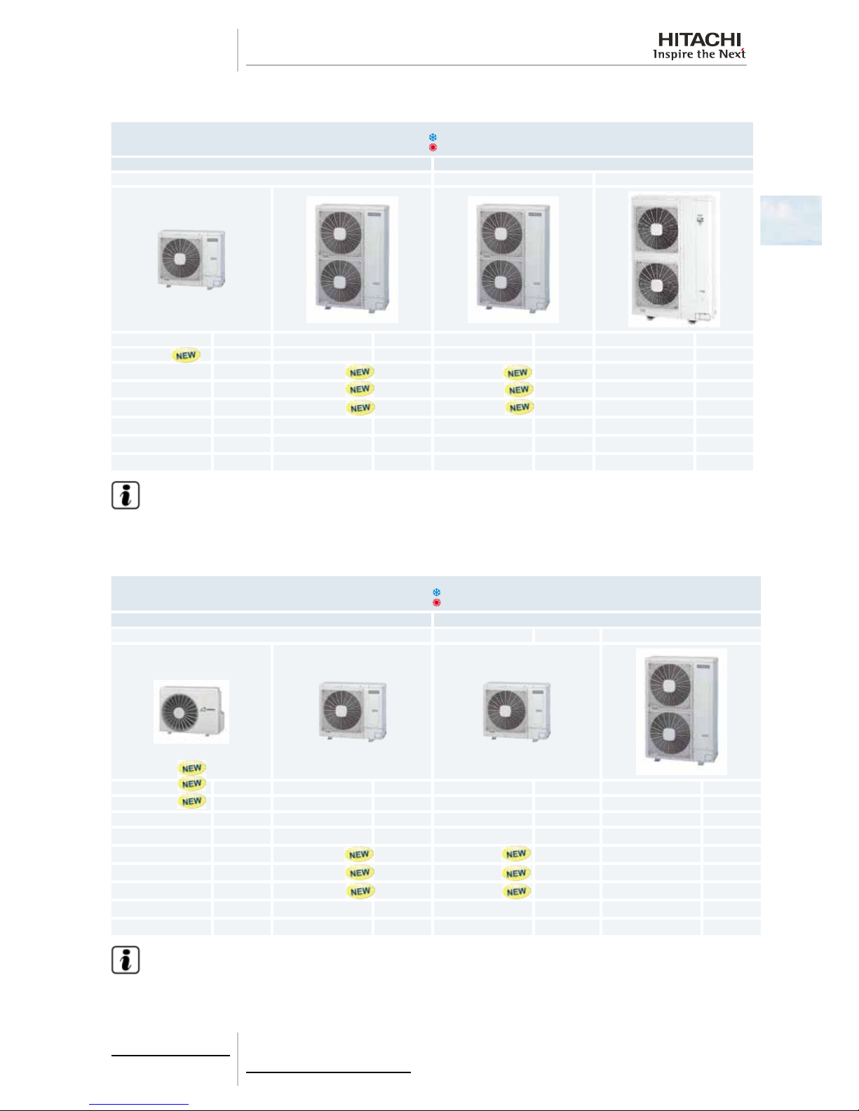
1.3.3 Product guide: Outdoor units
IVX series
Outdoor Units IVX
Single phase (1~) Three phase (3~)
HVRNM2E HRNM1E HRNM
Unit Code Unit Code Unit Code Unit Code
RAS-3HVRNM2E 7E305018
RAS-4HVRNM2E 7E305020 RAS-4HRNM2E 7E305120
RAS-5HVRNM2E 7E305021 RAS-5HRNM2E 7E305121
RAS-6HVRNM2E 7E305022 RAS-6HRNM2E 7E305122
RAS-8HRNM 60278972
RAS-10HRNM 60278973
RAS-12HRNM 60278974
N O TE
• Check the exact classication for each unit (model, type, power and series) in Classication of IVX series out-
door unit models, see on page 4.
ES series
Outdoor Units ES
Single phase (1~) Three phase (3~)
HVRN(2)(E) HRNSE
Unit Code Unit Code Unit Unit Code
RAS-2HVRN2 60288390 7E306107
RAS-2.5HVRN2 60288391 7E306108
RAS-3HVRNS2 60288392 7E306109
RAS-4HVRNS2E 7E306020 RAS-4HRNS2E
RAS-5HVRNS2E 7E306021 RAS-5HRNS2E
RAS-6HVRNS2E 7E306022 RAS-6HRNS2E
RAS-8HRNSE 7E314110
RAS-10HRNSE 7E314111
N O TE
• Check the exact classication for each unit (model, type, power and series) in Classication of ES series out-
door unit models, see on page 4 .
1 General information
6
SMGB0064 rev.0 - 08/2011
1.3.4 Accessory code list
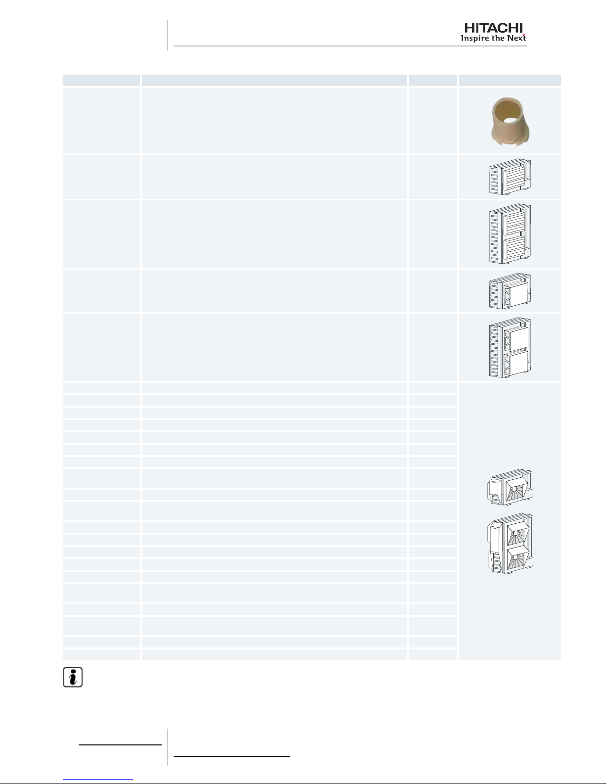
Name Description Code Figure
DBS-26 Drain discharge connection 60299192
AG-264 Air ow guide (For 2/2.5HP and 3HP ES) -
AG-335A Air ow guide (For 3-12HP IVX and 4-10HP ES) 60291431
WSP-264 Wind guard (For 2/2.5HP and 3HP ES) 60291728
WSP-335A Wind guard (For 3-12HP IVX and 4-10HP ES) 60291432
ASG-NP80F Snow protection hood; air outlet (Zinc plate) (For 2/2.5HP and 3HP ES) -
ASG-NP80FS2 Snow protection hood; air outlet (Stainless plate) (For 2/2.5HP and 3HP ES) -
ASG-NP335F Snow protection hood; air outlet (Zinc plate) (For 3-12HP IVX and 4-10HP ES) 60291433
ASG-NP335FS2 Snow protection hood; air outlet (Stainless plate) (For 3-12HP IVX and 4-10HP ES) -
ASG-NP56B Snow protection hood; air inlet of rear side (Zinc plate) (For 2/2.5HP and 3HP ES) -
ASG-NP63BS2 Snow protection hood; air inlet of rear side (Stainless plate) (For 2/2.5HP and 3HP ES) -
ASG-NP80B Snow protection hood; air inlet of rear side (Zinc plate) (For 3HP IVX and 4-6HP ES) -
ASG-NP160BS2
Snow protection hood; air inlet of rear side (Stainless plate) (For 3HP IVX and 4-6HP
ES)
-
ASG-NP280B Snow protection hood; air inlet of rear side (Zinc plate) (For 4-6HP IVX and 8/10HP ES) -
ASG-NP280BS2
Snow protection hood; air inlet of rear side (Stainless plate) (For 4-6HP IVX and
8/10HP ES)
-
ASG-NP335B Snow protection hood; air inlet of rear side (Zinc plate) (For 8-12HP IVX ) 60291434
ASG-NP335BS2 Snow protection hood; air inlet of rear side (Stainless plate) (For 8-12HP IVX ) -
ASG-NP56L Snow protection hood; air inlet of left side (Zinc plate) (For 2/2.5HP and 3HP ES) -
ASG-NP63LS2 Snow protection hood; air inlet of left side (Stainless plate) (For 2/2.5HP and 3HP ES) -
ASG-NP80L Snow protection hood; air inlet of left side (Zinc plate) (For 3HP IVX and 4-6HP ES) -
ASG-NP160LS2
Snow protection hood; air inlet of left side (Stainless plate) (For 3HP IVX and 4-6HP
ES)
-
ASG-NP280L Snow protection hood; air inlet of left side (Zinc plate) (For 4-6HP IVX and 8/10HP ES) -
ASG-NP280LS2
Snow protection hood; air inlet of left side (Stainless plate) (For 4-6HP IVX and 8/10HP
ES)
-
ASG-NP335L Snow protection hood; air inlet of left side (Zinc plate) (For 8-12HP IVX ) 60291435
ASG-NP335LS2 Snow protection hood; air inlet of left side (Stainless plate) (For 8-12HP IVX ) -
N O TE
HITACHI has a range of accessories and remote control systems that can be used with the UTOPIA outdoor units. Please,
refer to the Controls Technical Catalogue.+

2 Unit Installation
7
SMGB0064 rev.0 - 08/2011
2
U n i t I n s t a l l a t i o n
2.
Index
2.1. Safety summary ......................................................................................................................................8
2.2. Transportation of outdoor unit .................................................................................................................9
2.3. Center of gravity .................................................................................................................................... 10
2.4. Factory-supplied accessories for RAS-(8-12)HRNM............................................................................. 11
2.5. Installation space (Initial ckeck).............................................................................................................12
2.5.1. RAS-3HVRNM2E / RAS-(2-3)HVRN(S)2 / RAS-(4-10)H(V)RNS2E .......................................................... 12
2.5.2. RAS-(4-6)H(V)RNM2E / RAS-(8/10)HRNSE ............................................................................................. 16
2.5.3. RAS-(8-12)HRNM ...................................................................................................................................... 20
2.6. Place provision ...................................................................................................................................... 22
2.6.1. Place provision for RAS-(3-12)H(V)RNM(2)(E) and RAS-(4-10)H(V)RNS(2)E ......................................... 22
2.6.2. Place provision only for RAS-(2-3)HVRN(S)2 ........................................................................................... 25
2.7. Optional parts and installation ............................................................................................................... 28
2.7.1. Optional parts and installation for RAS-(2-3)HVRN(S)2 ............................................................................ 28
2.7.2. Optional parts and installation RAS-3HVRNM2E / RAS-(4-6)H(V)RNS2E ............................................... 33
2.7.3. Optional parts and installation RAS-(4-6)H(V)RNM2E / RAS-(8/10)HRNSE ........................................... 37
2.7.4. Optional parts and installation RAS-(8-12)HRNM ..................................................................................... 42
2 Unit Installation
8
SMGB0064 rev.0 - 08/2011
2.1 Safety summary
D A NG E R
• Install the outdoor unit with sufcient clearance around it for operation and maintenance as shown in the next
pages.
• Install the outdoor unit where good ventilation is available.
• Do not install the outdoor unit where exists a high level of oil mist salty air or sulphurous atmosphere.
• Install the outdoor unit as far as practical (being at least 3 meters) from electromagnetic wave radiator such
as medical equipment.
• Keep clearance between units of more than 50 mm and avoid obstacles that could hamper air intake when
installing more than one unit together.
• Install the outdoor unit in the shade or not exposed to direct sunshine or direct radiation from high temperature heat source.
• Do not install the outdoor unit in a place where a seasonal wind directly blows into the outdoor fan.
• For cleaning use non-inammable and nontoxic cleaning liquid. Use of inammable agent may cause explo-
sion or re.
• Work with sufcient ventilation for working in an enclosed space could cause oxygen deciency. Toxic gas
may be produced when cleaning agent is heated to high temperature by e.g. being exposed to re.
• Cleaning liquid shall be collected after cleaning.
• Pay attention not to clamp cables when attaching the service cover to avoid electric shock or re.
C A UT I O N
• Check the foundation to be at leveled and strongly enough.
• Install the unit in a restricted area not accessible by the general public.
• Aluminium ns have very sharp edges. Pay attention to the ns in order to avoid injury.
• Do not install the indoor units in a ammable environment to avoid a re or an explosion.
• Check to ensure that the ceiling slab is strong enough. If not strong enough the indoor unit may fall down on
you.
• Do not install the indoor units outdoor unit remote control switch and cable within approximately 3 meters
from strong electromagnetic wave radiators such as medical equipment.
• Do not install the indoor units in a machinery shop or kitchen where vapour from oil or mist ows to the indoor units. The oil will deposit on the heat exchanger thereby reducing the indoor unit performance and may
deform. In the worst case the oil damages the plastic parts of the indoor unit.
• To avoid any corrosive action to the heat exchangers do not install the indoor units in an acid or alkaline environment.
• When lifting or moving the indoor unit use appropriate slings to avoid damage and be careful not to damage
the insulation material on units surface.
• This appliance must be used only by adult and capable people having received the technical information or
instructions to handle properly and safely this appliance.
• Turn OFF all power switches before maintenance is performed.
• Do not start the cleaning procedures before 5 minutes of the stop of the unit.
D A NG E R
• Avoid obstacles which may hamper the air intake or the air discharge ow.
• Children must be supervised to ensure that they do not play with the electrical appliances.
• Before obtaining access to terminals all supply circuits bust be disconnected.
2 Unit Installation
9
SMGB0064 rev.0 - 08/2011
2
2.2 Transportation of outdoor unit
D A NG E R
Do not put any foreign material into the outdoor unit and check to ensure that none exists in the outdoor unit
before the installation and test run. Otherwise a re or failure will occur.
Hanging Method
When hanging the unit ensure the balance of the unit check safety and lift it up smoothly. Do not remove any packing materials and hang the unit under packing condition with two ropes as shown below.
RAS-3HVRNM2E RAS-(4-6)H(V)RNM2E
RAS-(2-3)HVRN(S)2 RAS-(8-12)HRNM
RAS-(4-6)H(V)RNS2E RAS-(8/10)HRNSE
1
A
B
C
D
1
A
B
C
D
1. Wire rope.
A. Over 60º.
B. 0.7 to 1.0 m.
C. Do not remove the plastic band or the corrugate paper frame.
D. Pass the wire ropes through each lifting hole in the wooden base as shown.
C A UT I O N
• Lift the outdoor unit in its factory packaging with 2 wire ropes.
• For safety reasons ensure that the outdoor unit is lifted smoothly and does not lean.
• Do not attach lifting equipment to the plastic band or the corrugated paper frame because of the ropes will slip
or break the materials.
• Ensure that the exterior of the unit is adequately protected with cloth or paper.
2 Unit Installation
10
SMGB0064 rev.0 - 08/2011
2.3 Center of gravity
Hanging Method
When hanging the unit ensure the balance of the unit check safety and lift it up smoothly. Do not remove any packing
materials and hang the unit under packing condition with two ropes as shown below. At leat two persons are needed to
move the unit.
RAS-(2-3)HVRN(S)2
a. 515 mm
b. 180 mm
h. 275 mm
1
RAS-3HVRNM2E
a. 590 mm
b. 185 mm
h. 370 mm
1
RAS-(4-6)H(V)RNS2E
For 4 HP:
a. 635 mm
b. 180 mm
h. 335 mm
For 5-6 HP:
a. 630 mm
b. 190 mm
h. 360 mm
RAS-(4-6)H(V)RNM2E
a. 615 mm
b. 190 mm
h. 570 mm
1
RAS-(8-12)HRNM
a. 615 mm
b. 190 mm
h. 570 mm
RAS-(8/10)HRNSE
For 8 HP:
a. 325 mm
b. 206 mm
h. 565 mm
For 10HP:
a. 325 mm
b. 213 mm
h. 585 mm
1 Center of gravity
2 Unit Installation
11
SMGB0064 rev.0 - 08/2011
2
2.4 Factory-supplied accessories for RAS-(8-12)HRNM
Make sure that the following accessories are packed with the unit.
N O TE
• If any of these accessories are not packed with the unit please contact your dealer.
Accessory Appearance
Quantity
RAS-8HRNM RAS-10HRNM RAS-12HRNM
Gasket
1 1 1
Pipe ange for refrigerant
gas piping
1 1 1
Ring core
1 1 1
Cable tie 1 1 1
Compressed sheet
1 1 1
2 Unit Installation
12
SMGB0064 rev.0 - 08/2011
2.5 Installation space (Initial ckeck)
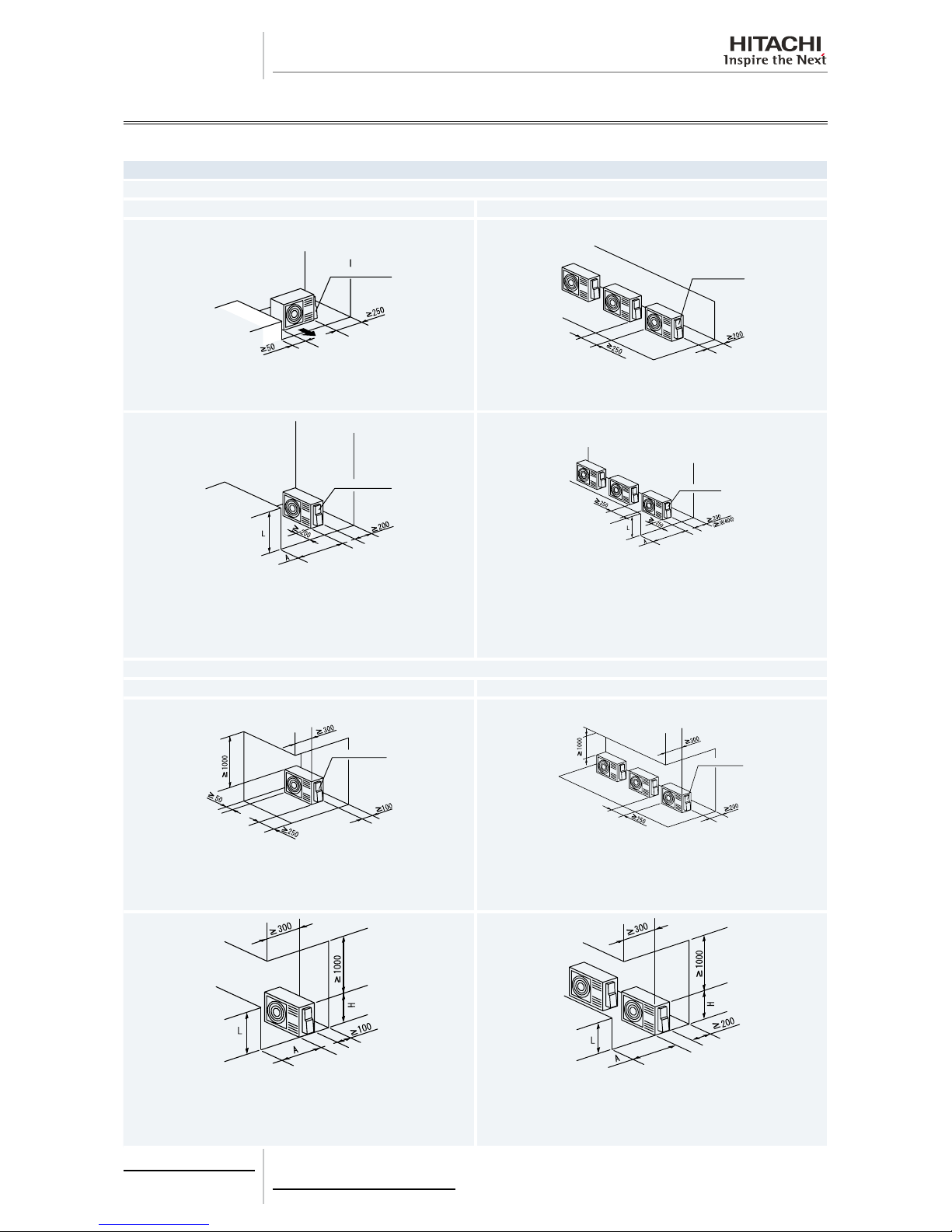
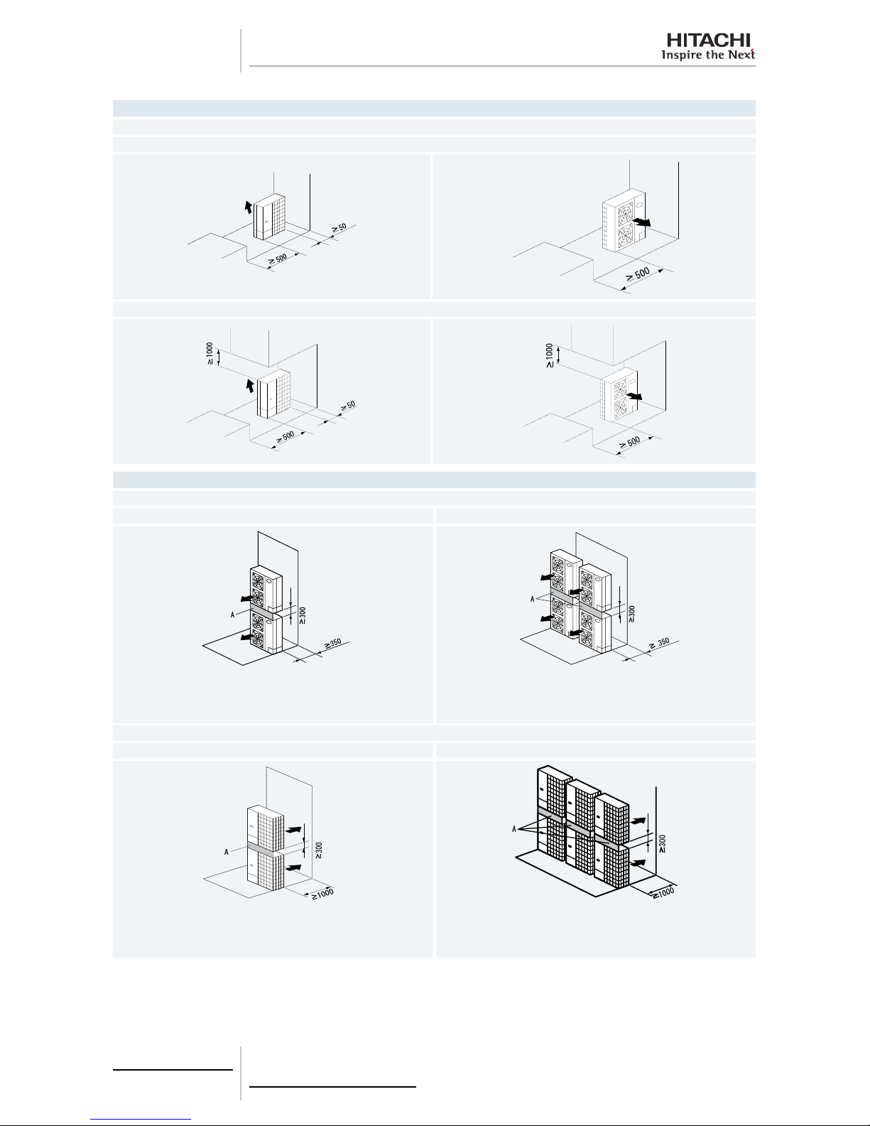
2.5.1 RAS-3HVRNM2E / RAS-(2-3)HVRN(S)2 / RAS-(4-10)H(V)RNS2E
Blocked in Inlet Side
Upper Side Open
Single Installation Multiple Installation (Two units or more)
Pipe Cover
Pipe Cover
Ensure 250 mm or more of the side space on the pipe cover side.
Allow 250 mm of space between units. Leave open both right and left
sides.
Pipe Cover
Pipe Cover
Be sure to use the fan direction guide. Leave open both right and left sides.
Ensure 250 mm or more of the side space on the pipe cover side.
Be sure to use the fan direction guide.
Allow 250 mm of service space between units. Leave open both right
and left sides. When subject to direct sunlight on the back wall ensure
the length marked with . be 400 or greater.
Ensure 250 mm or more of the side space on the pipe cover side.
Upper Side Blocked
Single Installation Multiple Installation (Two units or more)
Pipe Cover
Pipe Cover
Fifteen mm of space is acceptable for one of the lateral sides.
Ensure 250 mm or more of the side space on the pipe cover side.
Allow 250 mm of service space between units. Leave open both right
and left sides.
Ensure 250 mm or more of the side space on the pipe cover side.
Be sure to use the fan direction guide. Leave open both right and left sides.
Ensure 250 mm or more of the side space on the pipe cover side.
Be sure to use the fan direction guide.
Allow 250 mm of service space between units. Leave open both right
and left sides. Serial installation allowed up to two units.
Ensure 250 mm or more of the side space on the pipe cover side.

2 Unit Installation
13
SMGB0064 rev.0 - 08/2011
2
Blocked in Inlet Side
The length A is as show in the following table:
L A
0<L=1/2H 500 or greater
1/2H<L≤H 1000 or greater
When L > H use a base for outdoor unit to make L ≤ H.
Close the base not to allow the outlet air bypassed.
Outlet Side Blocked
Upper Side Open
Single Installation Multiple Installation (Two units or more)
Pipe Cover
Pipe Cover
Ensure 250 mm or more of the side space on the pipe cover side.
Allow 250 mm of service space between units. Both right and left sides
shall be open.
Pipe Cover
Pipe Cover
Be sure to use the fan direction guide. Leave open both right and left
sides.
Be sure to use the fan direction guide. Allow 250 mm of service space
between units. Serial installation allowed up to two units.
Leave open both right and left sides.
The length A is as show in the following table:
L A
0<L=1/2H 100 or greater
1/2H<L≤H 200 or greater
When L > H use a base for outdoor unit to make L ≤ H.
Close the base not to allow the outlet air bypassed.
The length A is as show in the following table:
L A
0<L=1/2H 150 or greater
1/2H<L≤H 250 or greater
When L > H use a base for outdoor unit to make L ≤ H.
Close the base not to allow the outlet air bypassed.

2 Unit Installation
14
SMGB0064 rev.0 - 08/2011
Lateral Side Blocked
Upper Side Open
Single Installation
Pipe Cover
Pipe Cover
Ensure 250 mm or more of the side space on the pipe cover side. Ensure 250 mm or more of the side space on the pipe cover side.
Upper Side Blocked
Pipe Cover
Pipe Cover
Ensure 250 mm or more of the side space on the pipe cover side. Ensure 250 mm or more of the side space on the pipe cover side.
2 Unit Installation
15
SMGB0064 rev.0 - 08/2011
2
Single Installation Multiple Installation
Blocked in Inlet Side
Pipe Cover
Pipe Cover
Close the part A not to allow the outlet air bypassed. Install to avoid the
drain water from upper unit falling on the lower unit.
Ensure 250 mm or more of the side space on the pipe cover side.
Allow 400 mm of service space above the top board.
Allow 250 mm of service space between units. Serial sideways installation allowed up to two units.
Leave open both right and left sides. Close the part A not to allow the
outlet air bypassed. Install to avoid the drain water from upper unit falling
on the lower unit.
Ensure 250 mm or more of the side space on the pipe cover side.
Allow 400 mm of service space above the top board.
Outlet Side Blocked
Pipe Cover
Pipe Cover
Be sure to use the fan direction guide. Close the part A not to allow the
outlet air bypassed. Install to avoid the drain water from upper unit falling
on the lower unit.
Ensure 250 mm or more of the side space on the pipe cover side.
Allow 400 mm of service space above the top board.
Be sure to use the fan direction guide. Allow 250 mm of service space
between units. Serial side way installation allowed but leave open both
right and left sides. Close the part A not to allow the outlet air bypassed.
Install to avoid the drain water from upper unit falling on the lower unit.
Ensure 250 mm or more of the side space on the pipe cover side.
Allow 400 mm of service space above the top board.
Multiple Installation in Multiple Rows
Ensure 250 mm or more of the side space on the pipe cover side. Allow
400 mm of service space above the top board.
The length A is as show in the following table:
L A
0<L=1/2H 150 or greater
1/2H<L≤H 250 or greater
When L > H use a base for outdoor unit to make L ≤ H. Close the base not to allow the outlet air bypassed. Be sure to use the fan direction guide in
order to ensure the length marked with ..
N O TE
• All units are in (mm).
• Do not stack more than two units in height.
• Close gap (*) to avoid recirculating discharge air ow.
2 Unit Installation
16
SMGB0064 rev.0 - 08/2011
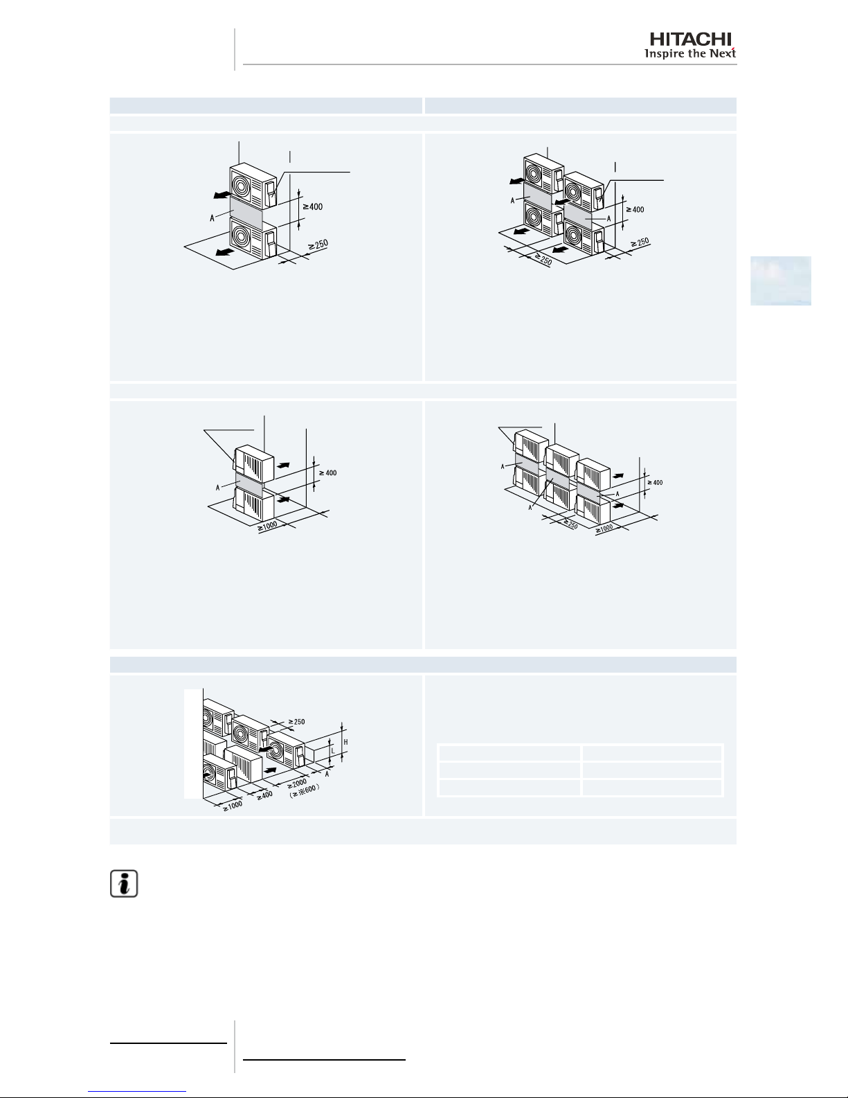
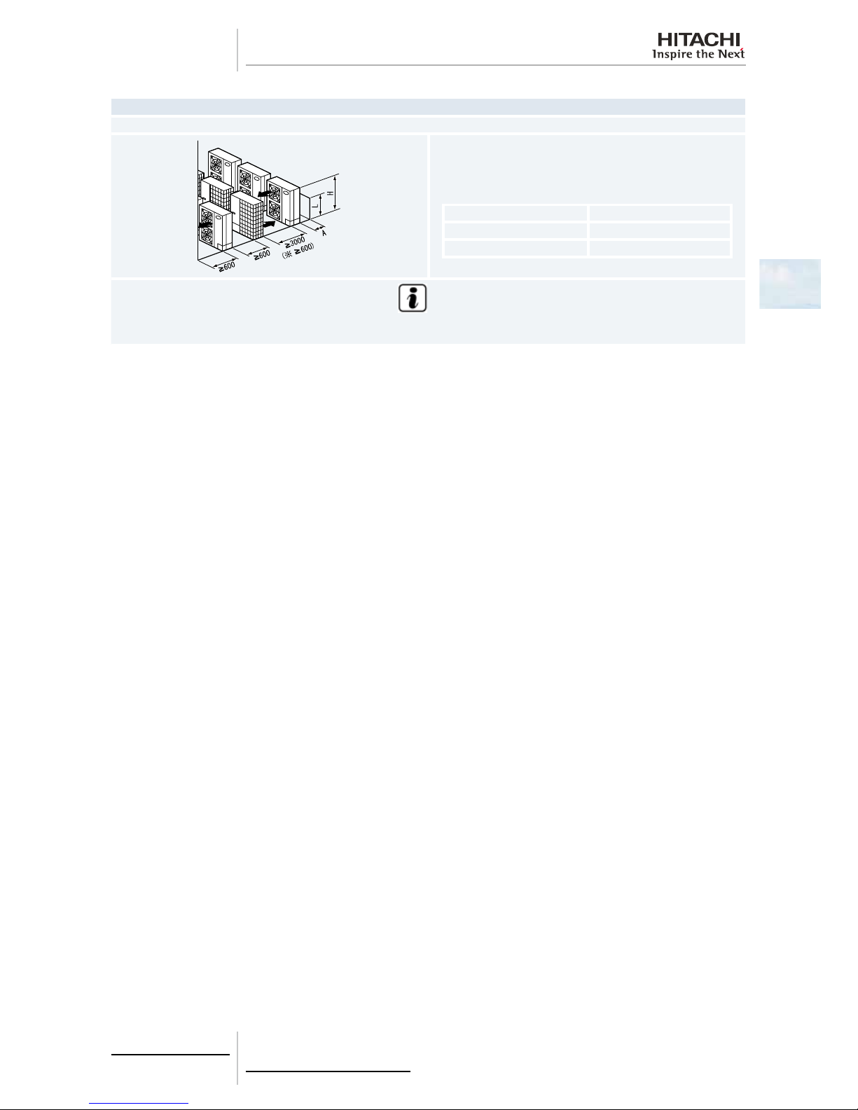
2.5.2 RAS-(4-6)H(V)RNM2E / RAS-(8/10)HRNSE
Blocked in Inlet Side
Upper Side Open
Single Installation Multiple Installation (Two units or more)
100 mm or more of the side space is acceptable on the service cover
side. Dimensions in ( ) shows numbers especially for IVX 4-10 HP and
ES 8/10 HP. 150 or more (200 or more) of the back space is acceptable
when the right and left sides are open.
Allow 100 mm of space between units. Leave open both right and left
sides.
Dimensions in ( ) shows numbers especially for IVX 4-10 HP and ES
8/10 HP.
Be sure to use the fan direction guide. Leave open both right and left
sides.
Be sure to use the fan direction guide. Allow 100 mm of space between
units. Leave open both right and left sides.
When subject to direct sunlight on the back wall ensure the length marked
with . be 500 or greater.
Upper Side Blocked
Single Installation Multiple Installation (Two units or more)
100 mm or more of the side space is acceptable on the service cover
side.
Dimensions in ( ) shows numbers especially for IVX 4-10 HP and ES
8/10 HP.
Allow 100 mm of space between units. Leave open both right and left
sides.
Dimensions in ( ) shows numbers especially for IVX 4-10 HP and ES
8/10 HP.
Be sure to use the fan direction guide.
Leave open both right and left sides.
Be sure to use the fan direction guide. Allow 100 mm of space between
units. Leave open both right and left sides.
Serial installation allowed up to two units.
2 Unit Installation
17
SMGB0064 rev.0 - 08/2011
2
Blocked in Inlet Side
The length A is as shown in the following table:
L A
0 < L ≤ 1/2H 600 or greater
1/2H < L≤ H 1200 or greater
Be sure to use the fan direction guide. Allow 100 mm of space between units. Leave open both right and left sides. Serial installation allowed up to
two units.
Outlet Side Blocked
Upper Side Open
Single Installation Multiple Installation (Two units or more)
Allow 100 mm of space between units. Both right and left sides shall be
open.
Be sure to use the fan direction guide. Leave open both right and left
sides.
Be sure to use the fan direction guide. Allow 100 mm of space between
units. Serial installation allowed up to two units. Leave open both right
and left sides.
The length A is as shown in the following table:
L A
0 < L ≤ 1/2H ≤ 200
1/2H < L≤ H ≤ 300
When L > H use a base for outdoor unit to make L ≤ H.
Close the base not to allow the outlet air bypassed.
The length A is as shown in the following table:
L A
0 < L ≤ 1/2H ≤ 250
1/2H < L≤ H ≤ 350
When L > H use a base for outdoor unit to make L ≤ H.
Close the base not to allow the outlet air bypassed.
2 Unit Installation
18
SMGB0064 rev.0 - 08/2011
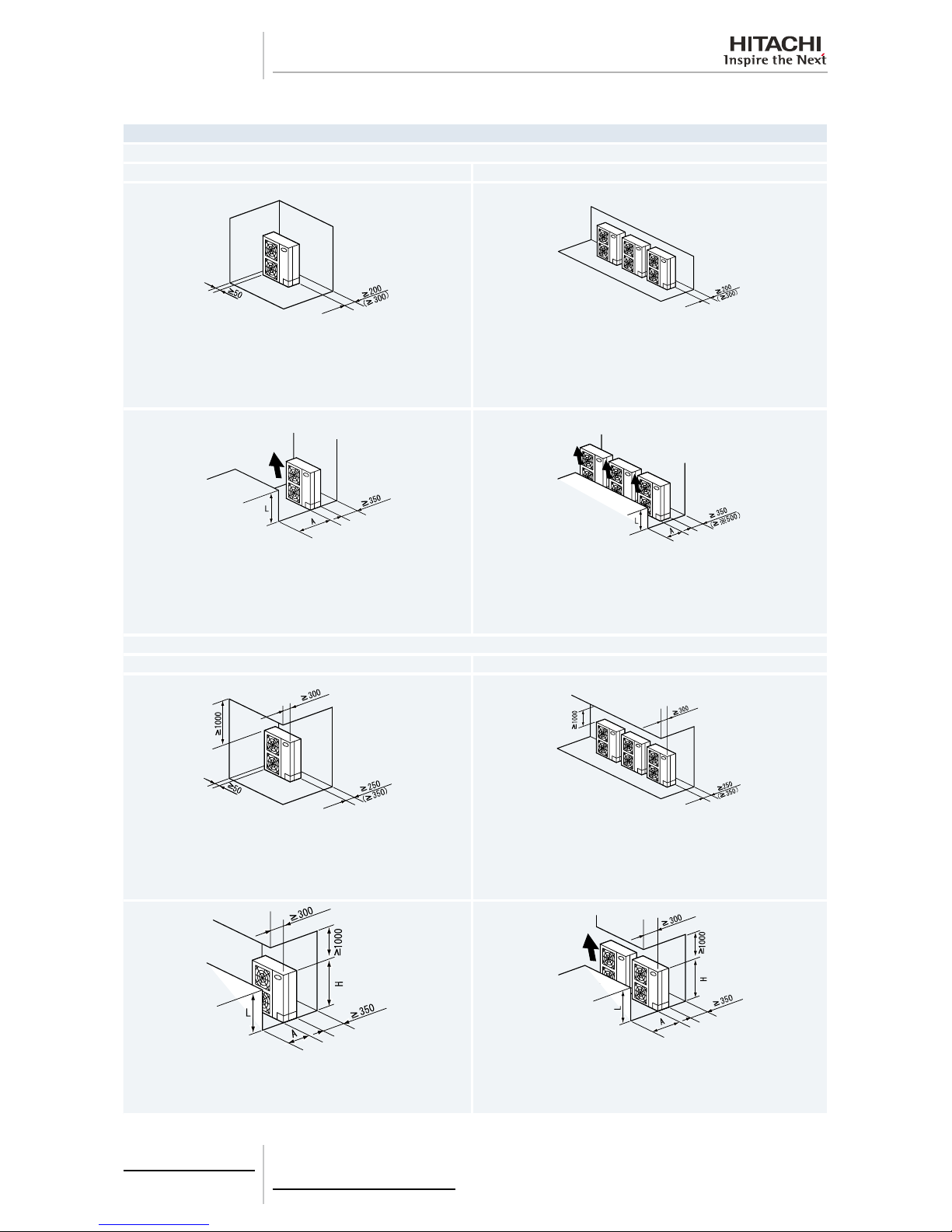
Lateral Side Blocked
Upper Side Open
Single Installation
Upper Side Blocked
Stack installation (allowed up to 2 Units)
Upper Side Open
Single Installation Multiple Installation
Close the part A not to allow the outlet air bypassed. Install to avoid the
drain water from upper unit falling on the lower unit.
Allow 100 mm of space between units. Serial sideways installation
allowed up to two units. Leave open both right and left sides. Close the
part A not to allow the outlet air bypassed. Install to avoid the drain water
from upper unit falling on the lower unit.
Upper Side Blocked
Single Installation Multiple Installation
Be sure to use the fan direction guide. Close the part A not to allow the
outlet air bypassed. Install to avoid the drain water from upper unit falling
on the lower unit.
Be sure to use the fan direction guide. Allow 100 mm of space between
units. Serial side way installation allowed. but leave open both right and
left sides. Close the part A not to allow the outlet air bypassed. Install to
avoid the drain water from upper unit falling on the lower unit.
2 Unit Installation
19
SMGB0064 rev.0 - 08/2011
2
Multiple Installation in Multiple Rows
Serial Installation in Multiple Rows (E.g. Rooftop)
Allow approx. 100 mm of space from the side unit. Leave open both right
and left sides.
The length A is as shown in the following table:
L A
0 < L ≤ 1/2H ≤ 200
1/2H < L≤ H ≤ 300
N O T E
When L > H use a base for outdoor unit to make L = H. Close the base not to allow the outlet air bypassed. Be sure to use the fan direction
guide in order to ensure the length marked with ..
2 Unit Installation
20
SMGB0064 rev.0 - 08/2011
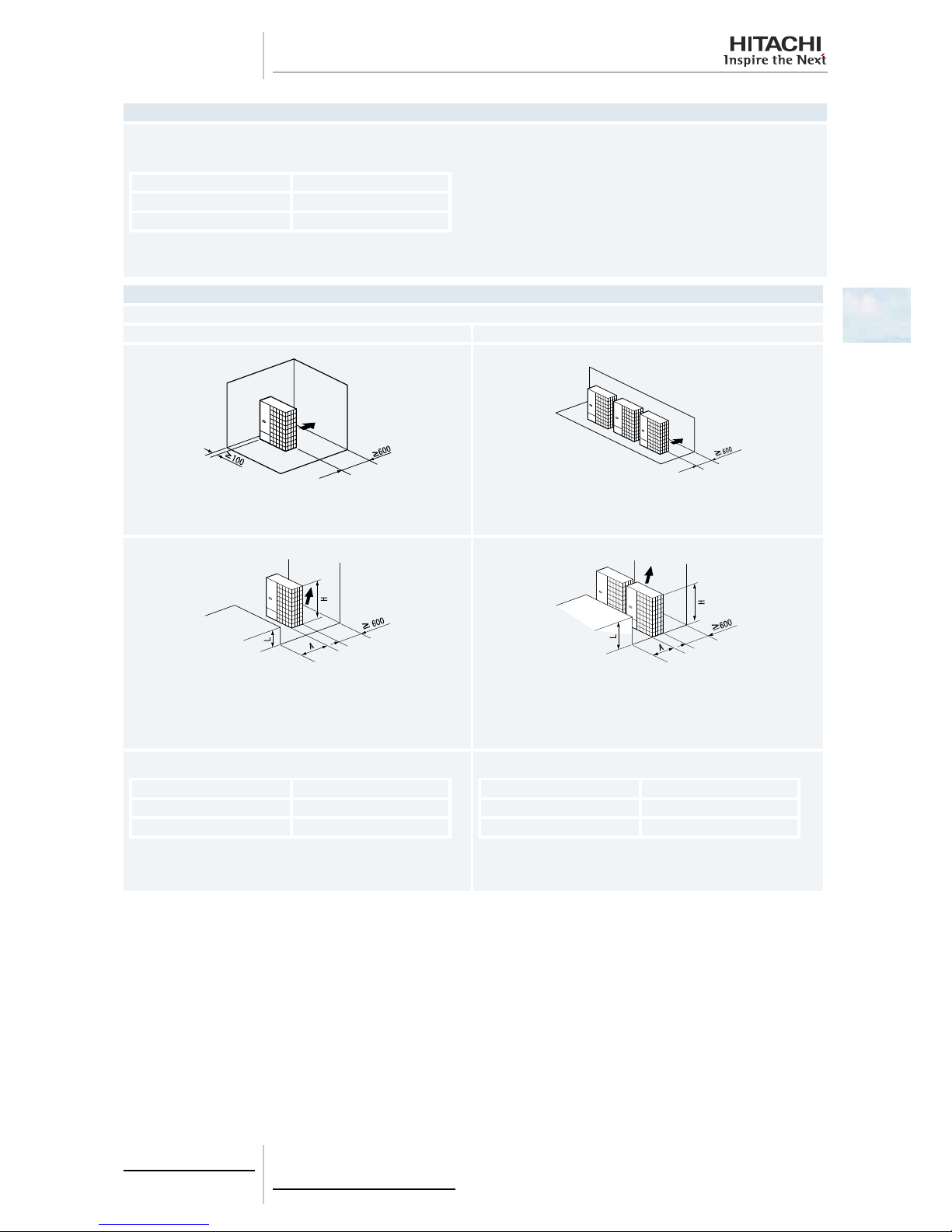
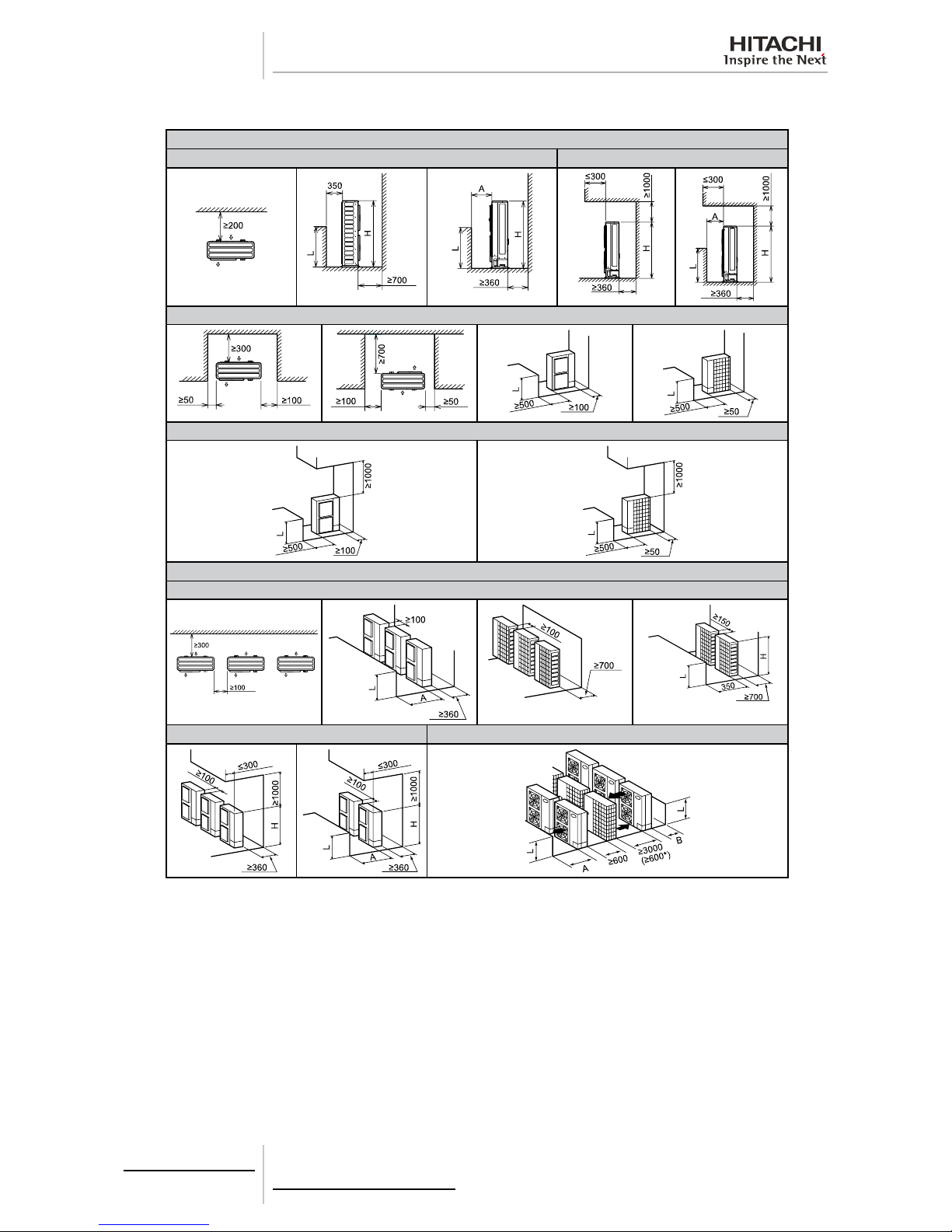
2.5.3 RAS-(8-12)HRNM
Single installation
Around sides are open Around sides are open with obstacles above
Around sides are closed
Around sides are open with obstacles above
Multiple installation
Around sides are open
Around sides are open with obstacles above
Multi-Row
 Loading...