

Hitachi RAS-3HVRNME-AF, RAS-5HVRNME-AF, RAS-4HVRNME-AF, RAS-6HVRNME-AF, RAS-5HRNME-AF Installation And Operation Manual
...Page 1
INSTALLATION AND OPERATION MANUAL
YUTAKI S/S80 Series
RAS-(3-6)H(V)RNME-AF
Outdoor Unit
Page 2

Page 3

Specications in this manual are subject to change without notice in order that HITACHI
may bring the latest innovations to their customers.
Whilst every effort is made to ensure that all specications are correct, printing errors are
beyond Hitachi’s control; Hitachi cannot be held responsible for these errors.
Page 4
ATTENTION:
This product shall not be mixed with general house waste at the end of its life and it shall be retired according to the
appropriated local or national regulations in a environmentally correct way.
Due to the refrigerant, oil and other components contained in Air Conditioner, its dismantling must be done by a
professional installer according to the applicable regulations.
Contact to the corresponding authorities for more information.
Page 5

DANGER – Immediate hazard which WILL result in severe injury or death.
WARNING – Hazards or unsafe practices which COULD result in severe personal injuries or death.
CAUTION – Hazards or unsafe practices which COULD result in minor personal injury or product or property
damage.
Page 6

Page 7
English
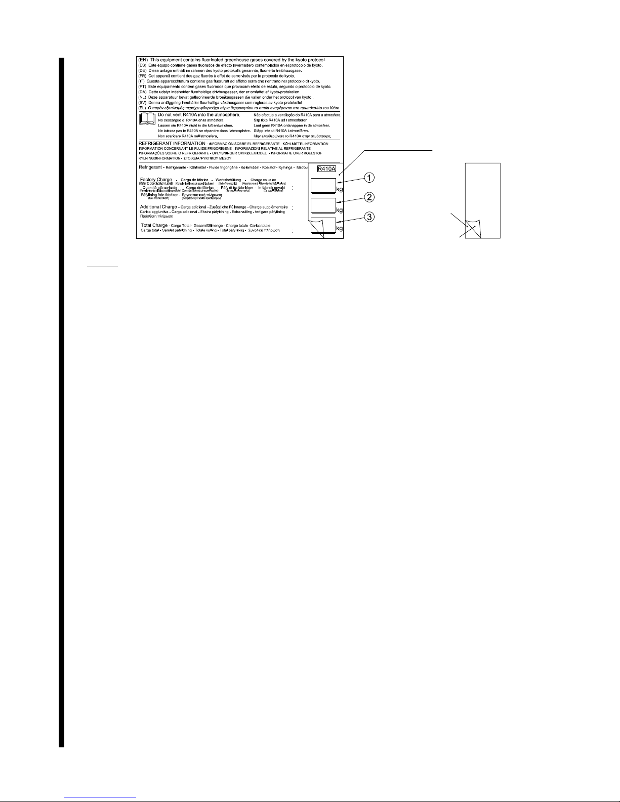
From 4th July 2007 and following Regulation EC Nº 842/2006 on Certain Fluorinated Greenhouse gases, it is mandatory to ll in the
label attached to the unit with the total amount of refrigerant charged on the installation.
Do not vent R410A/R407C into the atmosphere: R410A & R407C are uorinated greenhouse gases covered by the Kyoto protocol
global warming potential (GWP) R410A/R407C: = 1975/1652.5.
Page 8
English
Instructions to ll in the "F-Gas Label":
1.- Fill in the Label with indelible ink the refrigerant amounts:
- Factory Charge, - Additional Charge & - Total Charge.
2.- Stick the Protection Plastic Film on the F-Gas Label (delivered in a plastic bag with the Manual). To see Figure nº 2.
Figure 1. F-Gas Label with Protection Plastic Film Figure 2. Protection Plastic Film
Protection Plastic Film
Adhesive Surface
Peel-off Paper
Page 9

MODELS CODIFICATION
Important note: Please, check, according to the model name, which is your air conditioner type,
how it is abbreviated and referred to in this instruction manual. This Installation and Operation
Manual is only related to RWM-(H)FSN3E/RWH-FS(V)NFE combined with Outdoor Units H(V)
RNME-AF.
Page 10
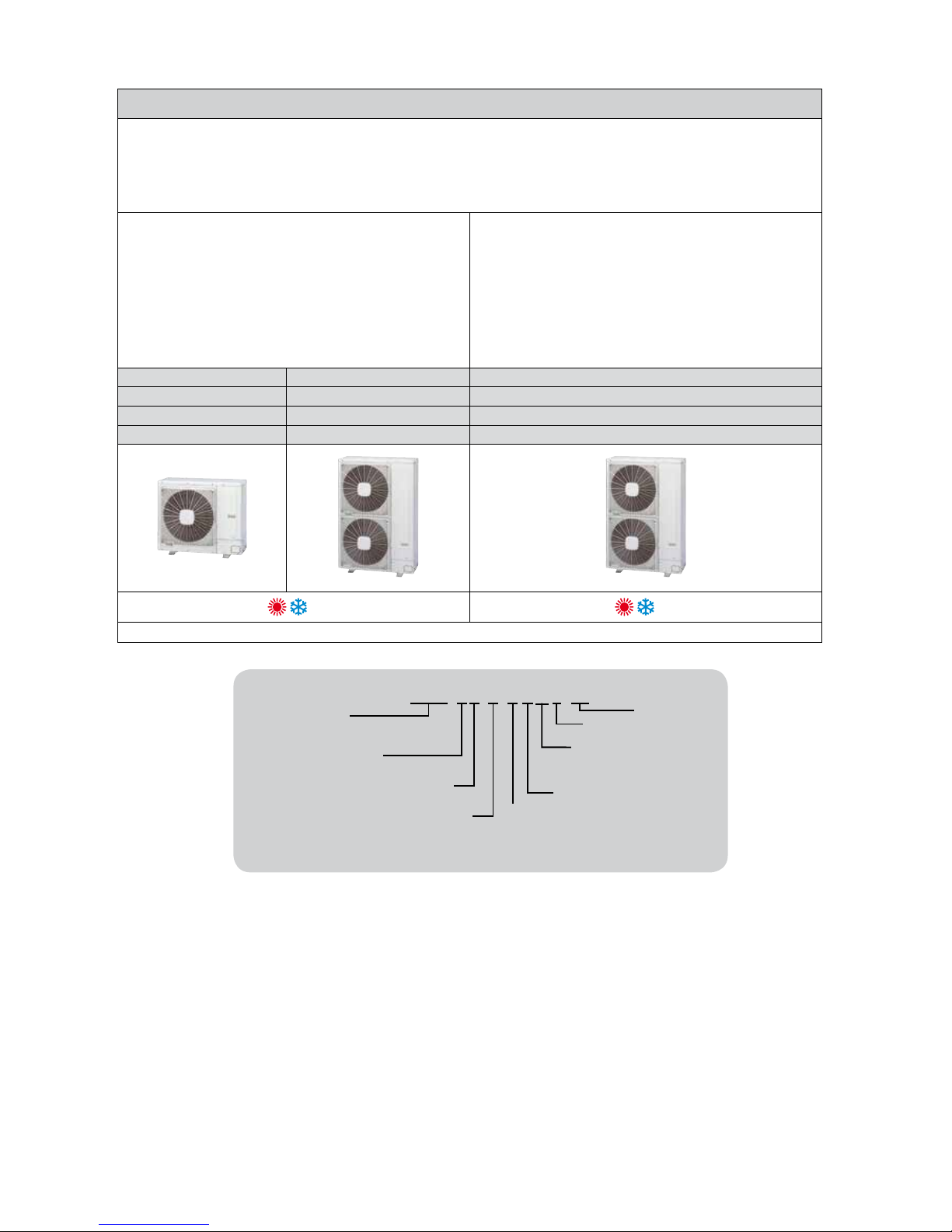
OUTDOOR UNIT · UNIDAD EXTERIOR · AUßENEINHEIT · UNITÉ EXTÉRIEURE · UNITÀ ESTERNA ·
UNIDADE EXTERIOR · UDENDRS AGGREGAT · BUITENTOESTEL · UTOMHUSENHET · ΕΞΩΤΕΡΙΚΗ ΜΟΝΑΔΑ
HEAT PUMP MODELS - MODELOS CON BOMBA DE CALOR
WÄRMEPUMPENMODELLE - MODÈLES POMPE À CHALEUR
MODELLI POMPA DI CALORE - MODELOS BOMBA DE CALOR
VARMEPUMPEMODELLER - MODELLEN MET WARMTEPOMP
MODELLER ENDAST FÖR KYLNINGSFUNKTION - ΜΟΝΤΕΛΑ ΜΕ ΑΝΤΛΙΑ ΘΕΡΜΟΤΗΤΑΣ
Single Phase
Monofásico
Einphasig
Monophasé
Monofase
Monofásico
Enfaset
Eenfasig
En fas
Μονοφασικά
Three Phase
Trifásico
Dreiphasig
Triphasé
Trifase
Trifásico
Trefaset
Driefasig
Trefasig
Tριφασικά
RAS-3HVRNME-AF
RAS-4HVRNME-AF RAS-4HRNME-AF
RAS-5HVRNME-AF RAS-5HRNME-AF
RAS-6HVRNME-AF RAS-6HRNME-AF
1~ 3N~
RAS
RAS-6H(V)RNME-AF
Unit type
(outdoor unit)
RAS
Compressor
Power (HP)
(3~6)
Heat Pump
Compressor type:
DC-Inverter
IVX Series
V: Single phase unit
(1~ 230V 50Hz)
-: Three phase unit
(3N~ 400V 50Hz)
R410A Refrigerant
E: Made in Europe
YUTAKI (S/S80)
Page 11
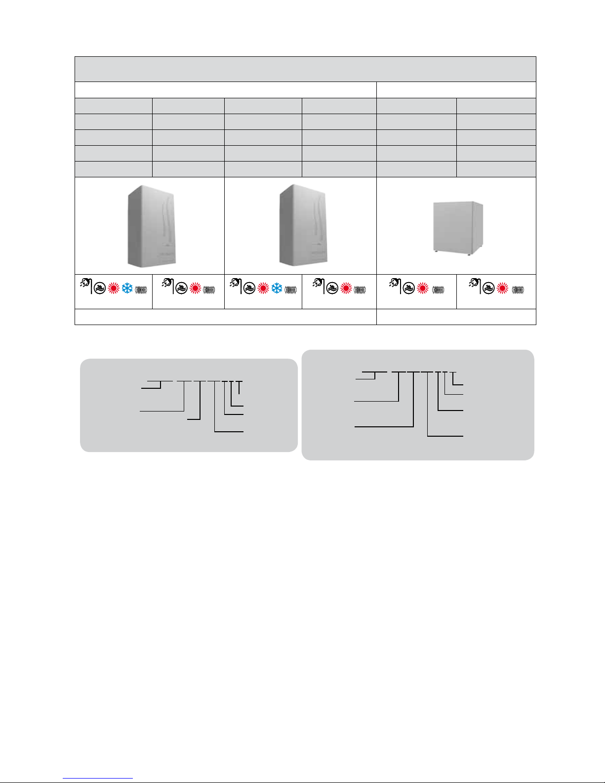
INDOOR UNIT - UNIDAD INTERIOR - INNENGERÄT - UNITÉ INTÉRIEURE - UNITÀ INTERNA -
UNIDADE INTERIOR - INDENDØRSENHED - BINNENUNIT - INOMHUSENHET - ΕΣΩΤΕΡΙΚΗ ΜΟΝΑ∆Α
YUTAKI S YUTAKI S80
Unit Unit Unit Unit Unit Unit
RWM-3.0FSN3E RWM-3.0HFSN3E
RWM-4.0FSN3E RWM-4.0HFSN3E RWH-4.0FSVNFE RWH-4.0FSNFE
RWM-5.0FSN3E RWM-5.0HFSN3E RWH-5.0FSVNFE RWH-5.0FSNFE
RWM-6.0FSN3E RWM-6.0HFSN3E RWH-6.0FSVNFE RWH-6.0FSNFE
1~
1~
1~/3N~
1~/3N~
1~
3N~
RWM RWH
RWM-5.0(H)FSN3E
Unit type:
indoor unit water
module - medium
temperature
Compressor
power (HP):
3.0, 4.0, 5.0, 6.0.
Made in Europe
Series
Refrigerant:
R410A
Only
heating
unit
System Free
RWH-5.0FS(V)NFE
Unit type:
indoor unit water
module - high
temperature
Compressor
power (HP):
4.0, 5.0, 6.0.
Made in Europe
Refrigerant:
R134a
Refrigerant:
R410A
V: Single phase unit
(1~ 230V 50Hz)
-: Three phase unit
(3N~ 400V 50Hz)
System Free
Page 12

INDEX ÍNDICE
PART I OPERATION
1. SAFETY SUMMARY
2. IMPORTANT NOTICE
3. SYSTEM DESCRIPTION
4. BEFORE OPERATION
5. AUTOMATIC CONTROLS
6. BASIC TROUBLESHOOTING
PART II INSTALLATION
7. NAME OF PARTS
8. REFRIGERANT CYCLE
9. UNITS INSTALLATION
10. REFRIGERANT PIPING & REFRIGERANT CHARGE
11. DRAIN PIPING
12. ELECTRIC WIRING
13. TEST RUN
14. SAFETY SUMMARY & CONTROL DEVICE SETTING
15. TROUBLESHOOTING
1ª PARTE FUNCIONAMIENTO
1. RESUMEN DE SEGURIDAD
2. AVISO IMPORTANTE
3. DESCRIPCIÓN DEL SISTEMA
4. ANTES DEL FUNCIONAMIENTO
5. CONTROLES AUTOMÁTICOS
6. RESOLUCIÓN DE PROBLEMAS BÁSICOS
2ª PARTE INSTALACIÓN
7. NOMBRE DE LAS PIEZAS
8. CICLO DE REFRIGERANTE
9. INSTALACIÓN DE LAS UNIDADES
10. TUBERÍA Y CARGA DE REFRIGERANTE
11. TUBERÍA DE DESAGÜE
12. CABLEADO ELÉCTRICO
13. PRUEBA DE FUNCIONAMIENTO
14. RESUMEN DE SEGURIDAD Y AJUSTE DE LOS
DISPOSITIVOS DE CONTROL
15. RESOLUCIÓN DE PROBLEMAS
INHALT INDEX
TEIL I – BETRIEB
1. SICHERHEITSÜBERSICHT
2. WICHTIGER HINWEIS
3. SYSTEMBESCHREIBUNG
4. VOR DEM BETRIEB
5. AUTOMATISCHE STEUERUNGEN
6. GRUNDLEGENDE FEHLERBEHEBUNG
TEIL II – INSTALLATION
7. TEILEBEZEICHNUNG
8. KÜHLKREISLAUF
9. GERÄTEINSTALLATION
10. KÄLTEMITTELROHRE UND KÄLTEMITTELMENGE
11. ABFLUSSLEITUNGEN
12. VERKABELUNG
13. TESTLAUF
14. SICHERHEITSÜBERSICHT UND EINSTELLUNG
DER STEUERGERÄTE
15. FEHLERBEHEBUNG
PARTIE I FONCTIONNEMENT
1. CONSIGNES DE SÉCURITÉ
2. REMARQUES IMPORTANTES
3. DESCRIPTION DU SYSTÈME
4. AVANT L’UTILISATION
5. CONTRÔLES AUTOMATIQUES
6. DÉPANNAGE DE BASE
PARTIE II INSTALLATION
7. NOMENCLATURE DES PIÈCES
8. CYCLE FRIGORIFIQUE
9. INSTALLATION DES UNITÉS
10. TUYAUTERIE FRIGORIFIQUE ET CHARGE DU
FLUIDE FRIGORIGÈNE
11. TUYAU D’ÉVACUATION
12. CÂBLAGE ÉLECTRIQUE
13. TEST DE FONCTIONNEMENT
14.
SOMMAIRE DES DISPOSITIFS DE SÉCURITÉ ET
RÉGLAGE DES DISPOSITIFS DE CONTRÔLE
15. DÉPANNAGE
INDICE ÍNDICE
PARTE I FUNZIONAMENTO
1. PRECAUZIONI PER LA SICUREZZA
2. NOTA IMPORTANTE
3. DESCRIZIONE DEL SISTEMA
4. PROCEDURA PRELIMINARE
5. CONTROLLI AUTOMATICI
6. RISOLUZIONE DEI PROBLEMI
PARTE II INSTALLAZIONE
7. NOMENCLATURA DEI COMPONENTI
8. CICLO REFRIGERANTE
9. INSTALLAZIONE DELLE UNITÀ
10.
LINEA DEL REFRIGERANTE E CARICA DI REFRIGERANTE
11. LINEA DI DRENAGGIO
12. COLLEGAMENTO DELLO SCHEMA ELETTRICO
13. PROVA DI FUNZIONAMENTO
14. RIEPILOGO DELLE IMPOSTAZIONI DEI DISPOSITIVI
DI CONTROLLO E SICUREZZA
15. RISOLUZIONE DEI PROBLEMI
PARTE I FUNCIONAMENTO
1. RESUMO DA SEGURANÇA
2. NOTA IMPORTANTE
3. DESCRIÇÃO DO SISTEMA
4. ANTES DE ARRANCAR A UNIDADE
5. CONTROLOS AUTOMÁTICOS
6. RESOLUÇÃO DE PROBLEMAS BÁSICOS
PARTE II INSTALAÇÃO
7. NOME DAS PEÇAS
8. CICLO DE REFRIGERAÇÃO
9. INSTALAÇÃO DAS UNIDADES
10. TUBAGEM E CARGA DE REFRIGERANTE
11. TUBAGEM DE ESGOTO
12. LIGAÇÕES ELÉCTRICAS
13. FUNCIONAMENTO DE TESTE
14. RESUMO DA SEGURANÇA E AJUSTE DE
DISPOSITIVO DE CONTROLO
15. RESOLUÇÃO DE PROBLEMAS
Page 13

INDEKS INHOUDSOPGAVE
DEL I – BETJENING
1. OVERSIGT OVER SIKKERHED
2. VIGTIG MEDDELELSE
3. SYSTEM BESKRIVELSE
4. FØR DRIFT
5. AUTOMATISKE KONTROLLER
6. BASIS FEJLFINDING
DEL II – MONTERING
7. NAVN PÅ DELE
8. KØLEMIDDELCYKLUS
9. INSTALLATION AF ENHEDER
10. KØLERØRSSYSTEM OG PÅFYLDNING AF
KØLEMIDDEL
11. AFLØBSRØR
12. ELEKTRISK LEDNINGSFØRING
13. TESTKØRSEL
14.
OVERSIGT OVER INDSTILLINGER FOR
SIKKERHEDS- OG KONTROLENHEDER
15. FEJLFINDING
DEEL I - BEDIENING
1. OVERZICHT VEILIGHEID
2. BELANGRIJKE MEDEDELING
3. BESCHRIJVING VAN HET SYSTEEM
4. VOORDAT U HET SYSTEEM IN GEBRUIK NEEMT
5. AUTOMATISCHE BESTURING
6. ELEMENTAIRE PROBLEMEN OPLOSSEN
DEEL II INSTALLATIE
7. NAMEN VAN ONDERDELEN
8. KOELMIDDELCYCLUS
9. INSTALLATIE VAN DE UNITS
10. KOELMIDDELLEIDINGEN & KOELMIDDEL VULLEN
11. AFVOERLEIDING
12. ELEKTRISCHE BEDRADING
13. PROEFDRAAIEN
14. OVERZICHT VEILIGHEID &
BESTURINGSINRICHTING
15. PROBLEMEN OPLOSSEN
INNEHÅLLSFÖRTECKNING ΕΥΡΕΤΗΡΙΟ
DEL I – DRIFT
1. SÄKERHETSSAMMANFATTNING
2. VIKTIG ANMÄRKNING
3. SYSTEMÖVERSIKT
4. FÖRE DRIFT
5. AUTOMATIK KONTROLLANORDNING
6. FELSÖKNING
DEL II - INSTALLATION
7. DELAR
8. KYLMEDIETS CYKEL
9. INSTALLATION AV ENHETER
10. KYLRÖR OCH PÅFYLLNING AV KYLMEDIUM
11. DRÄNERINGSRÖR
12. KABELANSLUTNINGAR
13. PROVKÖRNING
14. SÄKERHETSSAMMANFATTNING OCH
SÄKERHETSINSTÄLLNINGAR
15. FELSÖKNING
ΜΕΡΟΣ Ι ΛΕΙΤΟΥΡΓΙΑ
1. ΣΥΝΟΠΤΙΚΕΣ ΠΡΟΦΥΛΑΞΕΙΣ ΑΣΦΑΛΕΙΑΣ
2. ΣΗΜΑΝΤΙΚΗ ΠΑΡΑΤΗΡΗΣΗ
3. ΠΕΡΙΓΡΑΦΗ ΤΟΥ ΣΥΣΤΗΜΑΤΟΣ
4. ΠΡΙΝ ΤΗ ΛΕΙΤΟΥΡΓΙΑ
5. ΑΥΤΟΜΑΤΕΣ ΛΕΙΤΟΥΡΓΙΕΣ
6. ΑΝΤΙΜΕΤΩΠΙΣΗ ΒΑΣΙΚΩΝ ΠΡΟΒΛΗΜΑΤΩΝ
ΜΕΡΟΣ II ΕΓΚΑΤΑΣΤΑΣΗ
7. ΟΝΟΜΑΤΑ ΕΞΑΡΤΗΜΑΤΩΝ
8. ΚΥΚΛΟΣ ΨΥΞΗΣ
9. ΕΓΚΑΤΑΣΤΑΣΗ ΜΟΝΑΔΩΝ
10. ΣΩΛΗΝΩΣΕΙΣ ΨΥΚΤΙΚΟΥ & ΠΛΗΡΩΣΗ ΜΕ
ΨΥΚΤΙΚΟ ΜΕΣΟ
11. ΣΩΛΗΝΩΣΕΙΣ ΑΠΟΧΕΤΕΥΣΗΣ
12. ΗΛΕΚΤΡΙΚΗ ΚΑΛΩΔΙΩΣΗ
13. ΕΛΕΓΧΟΣ ΛΕΙΤΟΥΡΓΙΑΣ
14.
ΣΥΝΟΠΤΙΚΕΣ ΠΡΟΦΥΛΑΞΕΙΣ ΑΣΦΑΛΕΙΑΣ &
ΡΥΘΜΙΣΕΙΣ ΣΥΣΚΕΥΩΝ ΕΛΕΓΧΟΥ
15. ΑΝΤΙΜΕΤΩΠΙΣΗ ΠΡΟΒΛΗΜΑΤΩΝ
EN English Original version
ES Español Versión traducida
DE Deutsch Übersetzte Version
FR Français Version traduite
IT Italiano Versione tradotta
PT Português Versão traduzidal
DA Dansk Oversat version
NL Nederlands Vertaalde versie
SV Svenska Översatt version
EL ΕΛΛΗΝΙΚΑ Μεταφρασμένη έκδοση
Page 14

Page 15

15
PMML0205A rev.4 - 11/2012
ENGLISH
PART I- OPERATION
1 SAFETY SUMMARY
Identify the compatibility of the outdoor unit with YUTAKI S
and YUTAKI S80 indoor units by checking the black circle
into the indication poster.
YUTAKI S/S80
compatible
Verify, in accordance with the manuals which appear in the
outdoor units, that all the information required for the correct
installation of the system is included. If this is not the case,
contact your distributor.
HITACHI pursues a policy of continuing improvement in
design and performance of products. The right is therefore
reserved to vary specications without notice.
HITACHI cannot anticipate every possible circumstance that
might involve a potential hazard.
No part of this manual may be reproduced without written
permission.
If you have any questions, contact your service contractor of
HITACHI.
This manual gives a common description and information
for this heat pump which you operate as well as for other
models.
Check and make sure that the explanations of each part of
this manual correspond to your air conditioner model.
Refer to the models codication to conrm the main
characteristics of your system.
Signal words (DANGER, WARNING and CAUTION) are
used to identify levels of hazard seriousness. Denitions
for identifying hazard levels are provided below with their
respective signal words.
It is assumed that this unit will be operated and serviced by
English speaking people. If this is not the case, the customer
should add safety, caution and operating signs in the native
language of the personal.
This outdoor unit is exclusively to use for air to water
systems. It can not be used with indoor units in air to air
systems.
This heat pump has been designed for the following
temperature. Operate the air conditioner within this range:
Temperature
Maximum Minimum
Cooling Mode Outdoor 46 °C DB 10 °C DB
Heating Mode Outdoor 46 °C WB -20 °C WB
DB: Dry Bulb Temperature WB: Wet Bulb Temperature
These operations modes are controlled by the remote control
switch.
This manual should be considered as a permanent part of
the heat pump. This manual gives a common description and
information for this heat pump which you operate as well as
for other models.
DANGER:
Pressure Vessel and Safety Device: This heat pump is equipped
with a high pressure vessel under PED (Pressure Equipment
Directive). The pressure vessel has been designed and tested
before shipment according to PED. Also, in order to prevent the
system from an abnormal pressure, a high pressure switch, which
needs no eld adjustment, is utilized in the refrigeration system.
Therefore, this heat pump is protected from abnormal pressures.
However, if abnormally high pressure is applied to the refrigeration
cycle including the high pressure vessel(s), it will result in serious
injury or death due to explosion of the pressure vessel. Do not
apply a pressure higher than the following pressure to the system,
by modifying or changing the high pressure switch.
DANGER:
Do not pour water into the outdoor unit. These products are
equipped with electrical parts. If water contacts with electrical
components then it will cause a serious electrical shock.
Do not touch or adjust safety devices inside the indoor or
outdoor units. If these devices are touched or adjusted, it may
cause a serious accident.
Do not open the service cover or access the indoor or outdoor
units without disconnecting the main power supply.
In case of re Turn OFF the main switch, put out the re at once
and contact your service contractor.
CAUTION:
Refrigerant leakage can cause difculty with breathing due to
insufcient air.
WARNING:
Do not use any sprays such as insecticide, lacquer, hair spray or
other ammable gases within approximately one (1) meter from
the system.
If circuit breaker or fuse is often activated, stop the system and
contact your service contractor.
Do not make service or inspections tasks by yourself. This works
must be performed by qualied service person.
Do not put any strange material (sticks, etc...) into the air inlet
and outlet. These units have high speed rotating fans and it is
dangerous that any object touches them.
NOTE:
It is recommended to ventilate the room every 3 or 4 hours.
Yutaki S indoor unit has two different ranges:
- Heating and cooling version (RWM-(2.0-10.0)FSN3E).
- Heating only version (RWM-(2.0-10.0)HFSN3E).
All the information in this manual related to cooling operation, only
applies to heating and cooling version (RWM-(2.0-10.0)FSN3E).
Yutaki S80:
- Heating only version: RWH-(4.0-6.0)FS(V)NFE
2 IMPORTANT NOTICE
SAFETY SUMMARY
Page 16

PMML0205A rev.4 - 11/2012
16
3 SYSTEM DESCRIPTION
Maximum Allowable Pressure and High Pressure Cut-out Value:
Product Series Outdoor Unit Model Refrigerant
Maximun Allowable
Pressure (MPa)
High Pressure Switch
Cut-out Value (MPa)
H(V)RNME-AF Series RAS-3~6H(V)RNME-AF R410A 4.15 4.00 ~ 4.10
Supply electrical power to the system for approximately
12 hours before start-up or a long shutdown. Do not start
the system immediately after power supply, it may cause a
compressor failure because the compressor is not heated well.
When the system is started after a shutdown longer that
approximately 3 months, it is recommended to check the
system by your service contractor.
Turn OFF the main switch when the system is to be stopped
for a long period of time: If the main switch is not turned
OFF, electricity will be used, because the oil heater is always
energised during compressor stopping.
Make sure that the outdoor unit is not covered with snow or ice.
If covered, remove it by using hot water (approximately 50°C). If
the water temperature is higher that 50°C, it will cause damage
to plastic parts.
Start-up and Operation: Check to ensure that all the stop
valves are fully opened and no obstacle exists at the inlet/outlet
sides before start-up and during the operation.
Maintenance: Periodically check the high pressure side. If the
pressure is higher than the maximum allowable pressure, stop
the system and clean the heat exchanger or remove the cause.
NOTE:
The label for the vessel under PED are attached on the high
pressure vessel. The pressure vessel capacity and vessel
category are indicated on the vessel.
Location of High Pressure Switch
Compressor
NOTE:
The high pressure switch is indicated on the electrical wiring
diagram in the outdoor unit as PSH connected to printed circuit
board (PCB1) in the outdoor unit
Structure of High Pressure Switch
Contact Point Pressure Detected
Connected to the electrical wire
DANGER:
Do not change the high-pressure switch locally or change the
high pressure cut-out set value locally. If changed, it will cause
serious injury or death due to explosion.
Do not attempt to turn service valve rod beyond its stop
HITACHI’s YUTAKI S/S80 heat pumps produce sanitary hot water and heating like any oil or gas boiler but transforms renewable energy from the air outside into heat. Every 1kW of electricity used to power the heat pump can provide up to 4kW of energy for heating;
this can reduce heating bills by up to 60% and cut CO2 emissions by 50% compared to traditional boiler-led systems.
Furthermore, the YUTAKI S/S80 system allows a high exibility of indoor unit control thanks to its wireless remote controller (PCS80TE) which includes a helpful LCD graphic display, one-touch holiday button, weekly timer and frost protection, a high reliability,
space saving and easy installation.
NOTE:
For more information refer to indoor unit installation and operation manual PMML0228A(RWM-(2.0-6.0)FSN3E) or
PMML0258A(RWM-(2.0-6.0)HFSN3E) (YUTAKI S), PMML0224A(RWH-(4.0-6.0)FS(V)NFE) (YUTAKI S80).
4 BEFORE OPERATION
SYSTEM DESCRIPTION
CAUTION:
Page 17

17
PMML0205A rev.4 - 11/2012
ENGLISH
5 AUTOMATIC CONTROLS
The system is equipped with the following functions.
¡ THREE MINUTE GUARD
The compressor remains off for at least 3 minutes once it
has stopped. If the system is started within approximately 3
minutes after it has stopped, the RUN indicator is activated.
However, the cooling operation or the heating operation
remains off and does not start until after 3 minutes has
elapsed.
Operation may stop for 6 minutes maximum to protect
compressor.
¡ FROST PREVENTION DURING COOLING OPERATION
When the system is operated in a low temperature room,
the cooling operation may be changed to fan operation for a
while to avoid frost formation on the indoor heat exchanger.
¡ AUTOMATIC RESTART AFTER POWER FAILURE
If the power supply is interrupted for short periods of time
(up to 2 seconds) the Remote Control switch will retain the
settings and the unit will restart when the power is restored
(optional function).
If Automatic Restart is required after periods of lost power
supply in excess of 2 seconds please contact your distributor.
¡ SLOW AIR CONTROL DURING HEATING OPERATION
When the compressor is stopped while the thermostat is
OFF, or the system is performing the automatic defrosting
operation, the fan speed is set at the slow position.
¡ AUTOMATIC DEFROSTING CYCLE
When the heating operation is stopped by pressing RUN/
STOP switch, frosting on the outdoor unit is checked and the
defrosting operation may be performed for the maximum of
10 minutes.
¡ PREVENTION OF OVERLOAD OPERATION
When the outdoor temperature is too high during heating
operation, heating operation is stopped due to activation of
the outdoor thermistor until the temperature becomes low.
¡ HOT START DURING HEATING OPERATION
To prevent cold air discharge, the fan speed is controlled
from the slow position to the set position according to the
discharge air temperature. At this time the lover is xes
horizontally.
6 BASIC TROUBLESHOOTING
CAUTION:
When you smell or white smoke occurs from the unit, stop the
system and contact your contractor.
¡ THIS IS NOT ABNORMAL
− Sound from deforming Part
During system starting or stopping, and abrading
sound might be heard. However, this is due to thermal
deformation of plastic parts. It is not abnormal.
− Refrigerant Flow Sound
While the system is being started or stopping, sound from
the refrigerant ow may be heard.
− Steam from Outdoor Heat Exchanger
During defrosting operation, ice on the outdoor heat
exchanger is melted, resulting in making steam.
− Dew on Cabinet
When the cooling operation continues for a long period of
timer (higher than 27°C DB/80% R.H.), dew can form on
the cabinet.
¡ NO OPERATION
Check whether the SET TEMPERATURE is set at the correct
temperature.
¡ NOT COOLING WELL OR HEATING WELL
− Check the units to make sure that there are no outside air
ow obstructions or water ow obstructions inside.
− Check the level of the room’s heat load from other sources.
− Check if the water lter is clogged with dust.
− Check if the doors and windows are opened or closed.
− Check if the temperature condition is within the operating
range.
¡ IF TROUBLE STILL REMAINS...
If the trouble still remains even after checking the above
items, contact your service contractor and inform the
following data:
− Unit Model Name
− Content of Trouble
− Alarm Code nº. on LCD Controller
NOTE:
Except for a long period of shutdown, keep the main switch ON,
since the oil heater is energised when the compressor is stopped.
AUTOMATIC CONTROLS
Page 18

PMML0205A rev.4 - 11/2012
18
PART II-INSTALLATION
7 NAME OF PARTS
Name of parts. If do you want more information check the technical catalogue.
7.1. OUTDOOR UNIT (Example of RAS-5H(V)RNME-AF)
Nº. Part Name
1 Compressor
2 Heat Exchanger
3 Fan
4 Fan Motor
5 Strainer
6 Distributor
7 Reversing Valve
8 Expansion Valve
9 Solenoid Valve
10 Stop Valve for Gas Line
11 Stop Valve for Liquid Line
12 Receiver
13 Check Joint
14 Electrical Control Box
15 High-Pressure Switch
16 Pressure Switch
17 Crankcase Heater (for Compressor)
18 Vibration Isolation Rubber
19 Air Outlet
20 Air Inlet
NAME OF PARTS
Page 19

19
PMML0205A rev.4 - 11/2012
ENGLISH
8 REFRIGERANT CYCLE
EXAMPLE:
R410A 4.15 MPa
Refrigerant Flow
for Cooling
Refrigerant Flow
for Heating
Refrigerant Piping
in the installation
Connection With
Flare Nut
Flange Connection Brazing Connection Refrigerant
Airtight Test
Pressure
Nº. Name of Item Nº. Name of Item
1 Compressor 9 High Pressure Switch (Protection)
2 Heat Exchanger 10 Stop Valve for Gas Line
3 Filter 11 Stop Valve for Liquid Line
4 Expansion valve 12 Pressure Switch Control
5 Reverse Valve 13 Solenoid Valve
6 Filter (1/2) 14 Ambient Thermistor
7 Distributor 15 Evaporating Pipe Thermistor
8 Check Joint 16 Discharge Gas Thermistor
REFRIGERANT CYCLE
Page 20

PMML0205A rev.4 - 11/2012
20
9.1. OUTDOOR UNITS INSTALLATION
CAUTION:
Transport the products as close to the installation location as
practical before unpacking.
Do not put any material on the products.
Apply four lifting wires on to the outdoor, when lifting it by crane
WARNING:
- Install the outdoor unit with sufcient clearance around it for
operation and maintenance as shown in the next gures.
Install the outdoor unit where good ventilation is available
- Do not install the outdoor unit where is a high level of oil mist,
salty air or sulphurous atmosphere.
- Install the outdoor unit as far as practical (being at least 3
meters) from electromagnetic wave radiator (such as medical
equipment).
- For cleaning, use noninammable and nontoxic cleaning liquid.
Use of inammable agent may cause explosion or re.
- Work with sufcient ventilation, for working in an enclosed space
may cause oxygen deciency. Toxic gas may be produced when
cleaning agent is heated to high temperature by, e.g., being
exposed to re.
- Cleaning liquid shall be collected after cleaning.
- Pay attention not to clamp cables when attaching the service
cover to avoid electric shock or re.
CAUTION:
Keep clearance between the units of more than 50mm, and
avoid obstacles that may hamper air intake, when installing more
than one units together.
Install the outdoor unit in the shade or not exposed to direct
sunshine or direct radiation from high temperature heat source.
Do not install the Outdoor Unit in a space where a seasonal wind
directly blows to the Outdoor fan.
Check to ensure that the foundation is at, level and sufciently
strong.
Install the unit in a restricted area not accessible by the general
public
Aluminum ns have very sharp edges. Pay attention to the ns to
avoid injury.
9. UNITS INSTALLATION
UNITS INSTALLATION
Page 21

21
PMML0205A rev.4 - 11/2012
ENGLISH
9.1.1. INSTALLATION SPACE
− RAS-(3~6)H(V)RNME-AF
Blocked in Inlet Side
Upper Side Open
Single Installation Multiple Installation (Two units or more)
100 mm or more of the side space is acceptable on the service cover side.
Dimensions in ( ) shows numbers especially for 4 – 6 HP. 150 or more (200 or
more) of the back space is acceptable when the right and left sides are open.
Allow 100mm of space between units. Leave open both right and left sides.
Dimensions in ( ) shows numbers especially for 4 – 6 HP.
Be sure to use the fan direction guide. Leave open both right
and left sides.
Be sure to use the fan direction guide. Allow 100 mm of
space between units. Leave open both right and left sides.
When subject to direct sunlight on the back wall, ensure the
length marked with
be 500 or greater.
Upper Side Blocked
100 mm or more of the side space is acceptable on the service cover side.
Dimensions in ( ) shows numbers especially for 4 – 6 HP.
Allow 100 mm of space between units. Leave open both right and left sides.
Dimensions in ( ) shows numbers especially for 4 – 6 HP.
Be sure to use the fan direction guide.
Leave open both right and left sides.
H
Be sure to use the fan direction guide. Allow 100 mm of
space between units. Leave open both right and left sides.
Serial installation allowed up to two units.
L
H
Be sure to use the fan direction guide. Allow 100 mm of space between units.
Leave open both right and left sides. Serial installation allowed up to two units.
The length A is as shown
in the following table:
L A
0 <L≦
1/2H
600 or greater
1/2H
<L≦
H
1200 or greater
UNITS INSTALLATION
Page 22

PMML0205A rev.4 - 11/2012
22
Outlet Side Blocked
Upper Side Open
Single Installation Multiple Installation (Two units or more)
Allow 100mm of space between units. Both right and left
sides shall be open.
Be sure to use the fan direction guide. Leave open
both right and left sides.
H
L
Be sure to use the fan direction guide. Allow 100 mm of space
between units. Serial installation allowed up to two units. Leave
open both right and left sides.
H
l
The length A is as shown
in the following table:
When L > H, use a base for outdoor unit to make L ≤ H.
Close the base not to allow the outlet air bypassed.
L A
0<L≤1/2H ≤200
1/2H<L≤H ≤300
The length A is as shown
in the following table:
When L > H, use a base for outdoor unit to make L ≤ H.
Close the base not to allow the outlet air bypassed.
L A
0<L≤1/2H ≤250
1/2H<L≤H ≤350
Lateral Side Blocked
Upper Side Open
Single Installation
Upper Side Blocked
UNITS INSTALLATION
Page 23

23
PMML0205A rev.4 - 11/2012
ENGLISH
Stack installation (allowed up to 2 Units)
Blocked in Inlet Side
Single Installation Multiple Installation
Close the part A not to allow the outlet air bypassed. Install to avoid
the drain water from upper unit falling on the lower unit.
Allow 100 mm of space between units. Serial sideways installation
allowed up to two units. Leave open both right and left sides. Close the
part A not to allow the outlet air bypassed. Install to avoid the drain water
from upper unit falling on the lower unit
Outlet Side Blocked
Be sure to use the fan direction guide. Close the part A not to allow
the outlet air bypassed. Install to avoid the drain water from upper
unit falling on the lower unit.
Be sure to use the fan direction guide. Allow 100mm of space between
units. Serial sideway installation allowed. but leave open both right and
left sides. Close the part A not to allow the outlet air bypassed. Install to
avoid the drain water from upper unit falling on the lower unit.
Multiple Installation in Multiple Rows
Serial Installation in Multiple Rows (E.g. Rooftop)
Allow approx. 100 mm of space from the side unit.
Leave open both right and left sides.
The length A is as shown in the following table:
L A
0<L≤1/2H
≤
200
1/2H<L≤H
≤
300
L
H
Note: When L > H, use a base for outdoor unit to make L ≤ H. Close the base not to allow the outlet air bypassed. Be sure to
use the fan direction guide in order to ensure the length marked with .
- Do not stack more than two units in height.
UNITS INSTALLATION
Page 24

PMML0205A rev.4 - 11/2012
24
9.1.2. INSTALLATION PLACE PROVISION
¡
Concrete Foundation
1. Foundation could be on at and is recommended be 100-300
mm higher than ground level.
2. Install a drainage around foundation for smooth drain.
3. When installing the outdoor unit x the unit by anchor bolts of
M10.
4. When installing the unit on a roof or a veranda, drain water
sometimes turns to ice on a cold morning. Therefore, avoid
draining in an area that people often use because it is
slippery.
* Space for downward piping space
Nº Description
Outdoor Unit
Cut this portion of bolt If not, it’s difcult to remove Service Cover
Mortar Hole (Ø100xDepth 150)
Anchor Bolt M10 (Ø12.5 Hole)
Drainage (Wide 100xDepth 150)
Drainage
Vibration-proof rubber
5. The whole of the base of the outdoor unit should be installed
on a foundation. When using vibration-proof mat, it should
also be positioned the same way. When installing the outdoor
unit on a eld supplied frame, use metal plates to adjust the
frame width for stable installation as shown in below gure.
INCORRECT
CORRECT
Outdoor unit is
stable
57 mm
Outdoor unit base width
Frame
Metal plate
100 mm or more
Metal plate
Recommended Metal Plate Size
- (Field-Supplied) Material: Hot-Rolled Mild Steel
- Plate (SPHC) Plate Thickness: 4.5 T
Outdoor unit is
unstable
Frame
60mm
Frame width
(Field supplied)
Base width of outdoor unit
57 mm
UNITS INSTALLATION
Page 25

25
PMML0205A rev.4 - 11/2012
ENGLISH
10.1. PIPING MATERIALS
1. Prepare locally-supplied copper pipes.
2. Select the piping size with the correct thickness and
correct material which can have sufcient pressure
strength.
3. Select clean copper pipes. Make sure there is no dust and
moisture inside. Blow the inside of the pipes with oxygen
free nitrogen to remove any dust and foreign materials
before connecting pipes.
NOTE:
A system with no moisture or oil contamination will give maximum
performance and lifecycle compared to that of a poorly prepared
system. Take particular care to ensure all copper piping is clean
and dry internally.
There is no refrigerant in the cycle of the indoor unit.
CAUTION:
Cap the end of the pipe when pipe is to be inserted through a
hole.
Do not put pipes on the ground directly without a cap or vinyl tape
at the end of the pipe
If piping installation is not completed until next day or over a
longer period of time, braze off the ends of the piping and charge
with oxygen free nitrogen through a Schrader valve type access
tting to prevent moisture and particle contamination.
Do not use insulation material that contains NH3 because it can
damage cooper pipe material and can be a source of future
leakage.
Insulate the unions and are-nuts at the piping connection part
completely.
Completely insulate both refrigerant gas and liquid piping between
the indoor unit and the outdoor unit to avoid a decrease of
performance; if not, dew will occur on the piping surface.
¡ Fix Unit to the wall
1. Fix the Unit onto the wall as the gure
indicates. (eld supplied stay)
2. Ensure the foundation so that avoid the
deforming and noise.
3. In case of prevention from vibration
transfer to the building, use rubber Mat.
¡ Suspended unit
1. Suspend the unit as the drawing
indicates.
2. Ensure that wall can resist the Outdoor
unit weight indicated in specication
label plate.
3. It is recommended to select each foot
support to bear the full weight of the
unit (in order to consider stress fatigue
applied when unit is working too).
CAUTION:
Pay attention to the following for
installation:
1. Installation shall ensure that outdoor
unit will not incline, vibrate, make
noise or fall down by a blast of
wind or in an earthquake. Calculate
quake-resistance strength to
ensure that installation is strong
enough against falling. Fix the unit
with wires (eld supplied) when
installing in a location without walls
or windbreak and likely exposed to
a blast of wind.
2. To use a vibration-proof mat, x four
places to the front and back.
¡ Installing location where the unit will be exposed to strong wind.
Follow the instructions below to install
on the rooftop or a location without
surrounding buildings, where strong
wind is expected against the product.
1. Choose a location where the outlet
or inlet side of the product will not be
exposed to strong wind.
2. When the outlet is exposed to strong
wind:
Direct strong wind may cause lack
of air ow and adversely affect to the
operation.
CAUTION:
Excessive strong wind against the
outdoor unit outlet may cause inverse
rotation and damage the fan and
motor.
10. REFRIGERANT PIPING & REFRIGERANT CHARGE
Mark Dimension
Model 3HVRNME-AF
4~6H(V)RNME-AF
A (mm) 529 796
Wall bracket (*)
Anchor Bolts (*)
(*) Field supplied
Rubber Material
(Field Supplied)
REFRIGERANT PIPING &
REFRIGERANT CHARGE
Page 26

PMML0205A rev.4 - 11/2012
26
10.2. SUSPENSION OF REFRIGERANT PIPING
Suspend the refrigerant piping at certain points and prevent the
refrigerant piping from touching the weak part of the building
such as wall, ceiling, etc…
(If touched, abnormal sound may occur due to the vibration of
the piping. Pay special attention in case of short piping length).
Do not x the refrigerant piping directly with the metal ttings
(The refrigerant piping may expand and contract).
Some examples for suspension method are shown below.
10.3. PIPING CONNECTION FOR OUTDOOR UNIT
1. The pipes can be connected from 4 directions. Make holes
in the piping cover or cabinet for taking out pipes. Take the
piping cover away from the unit, and make holes by cutting
along the guideline at the rear of the cover or punching with
a driver. Remove the burr with a cutter, and place a insulation
(eld supplied) to protect cables and pipes.
Nº Description
Rear side piping work
Pipe Cover
Right side piping work
Bottom side piping work (Knock out hole)
Front side piping work
Piping work
Stop Valve
Removing Direction for Service Cover
CAUTION:
Notes to open/close the service cover:
Remove the screws following the instructions to the above gure.
Slowly press down the cover
NOTE:
Hold the cover with a hand to remove screws as the cover may fall
down.
¡ For the front and side piping
To use racking or conduit tubes, check the size and remove
part following the slit.
NOTE:
Place insulation (eld supplied) to protect cables and pipes from
being damaged by plate edges.
¡ For the downward piping
NOTE:
Cables shall not contact directly to the pipes.
¡ For the rear side piping
NOTE:
Remove the rear pipe cover under the rear cover and remove
part following the slit.
For Suspending
Heavies
For piping along
the wall
For instant
installation work
1~15m
Indor unit
Fire-Proof
Section
Treatment
Front piping hole
Side piping hole
Gas piping
Knock-out hole
Bottom base
Cables
Liquid piping
Service cover
Hook (three places): two fans
Hook (two places): one fan
Rear Cover
REFRIGERANT PIPING &
REFRIGERANT CHARGE
Page 27

27
PMML0205A rev.4 - 11/2012
ENGLISH
2. Mount the piping cover in order to avoid water entering into
the unit. Seal the holes where pipes and wires are inserted,
by using a insulation (eld-supplied).
3. If the eld-supplied piping is connected with stop valves
directly, it is recommended use a tube bender.
4. Check to ensure that the stop valves are closed completely
before connecting pipes.
5. Connect the eld supplied refrigerant pipes to the indoor unit
and outdoor unit. Apply the oil thinly at the seat are nut and
pipe before tightening.
The required tightening torque is as follows:
Pipe Size Tightening Torque (Nm)
Ø 6.35 mm 20
Ø 9.53 mm 40
Ø 12.70 mm 60
Ø 15.88 mm 80
6. After connecting the refrigerant piping, seal the open space
between knockout hole and refrigerant pipes by using
insulation material.
Unit
Side
Nº Description
Insulation Material
Insulation Material
Field Supplied
Insulation Material
7. Operation of stop valve should be performed according to the
gure below.
Close before shipment
Nº Description Remaks
Cap
Allen wrench Hex 4 mm
Refrigerant Piping Field Supplied
Cap
Refrigerant Pressure To Outdoor Unit
Seat Surface Fully closed position
Check Joint Only the charging those can be connected
Cap
O-Ring Rubber
Spindle valve
Open – Counterclockwise
Close – Clockwise
Tighten torque (N.m)
Valve type / Model A B C D
Liquid Valve: 3~6HP 7~9 34~42 34~42 14~18
Gas Valve: 3~6HP 9~11 34~42 68~82 14~18
¡ Outdoor unit stop valve
Do not apply two
spanners at this
position. If applied,
leakage will occur.
Stop valve
Flare nut
CAUTION:
At the test run, fully open the spindle.
If not fully opened, the devices will be damaged.
Do not attempt to turn service valve rod beyond its stop.
Do not loosen the stop ring. If the stop ring is loosened, it is
dangerous since the spindle will hop out.
10.4. REFRIGERANT PIPING
The refrigerant piping between the indoor unit and the outdoor
unit should be designed using the following chart.
Keep the design point within the dark area of the chart, which
is showing the applicable height difference according to piping
length.
10.4.1. REFRIGERANT PIPING LENGHT
When outdoor
unit is installed
higher than
indoor unit
When outdoor
unit is installed
lower than indoor unit
Height difference
(m)
Total length between outdoor unit
and indoor unit.
40
Setting of Pipe Length DSW.
DSW2 setting will be required only when the refrigerant
pipe length is shorter than 5 m. Pipe length setting shall be
performed as shown below.
(The side in the table below shows the DSW location)
DSW2 on Outdoor PCB1
Factory setting Installer setting
Pipe length between 5 m and 30 m Pipe Length 5 m or shorter
REFRIGERANT PIPING &
REFRIGERANT CHARGE
Page 28

PMML0205A rev.4 - 11/2012
28
Example of YUTAKI S80
refrigerant piping length
Maximum piping length between
outdoor unit and indoor unit (Lmax)
Actual piping length 30 m
Equivalent piping length 40 m
Minimum piping length between
outdoor unit and indoor unit (Lmin)
Actual piping length 3 m
Maximum height difference bet-
ween indoor and outdoor unit (H)
Outdoor unit higher
than indoor unit
30 m
Indoor unit higher than
outdoor unit
20 m
10.4.2. REFRIGERANT PIPING SIZE
Piping connection size of Outdoor Unit & Indoor Unit
Outdoor Unit
Pipe Size
Gas Pipe Liquid Pipe
(3 ~ 6) HP Ø 15.88 (5/8”) Ø 9.53 (3/8”)
Indoor Unit
Pipe Size
Gas Pipe Liquid Pipe
(3 ~ 6) HP Ø 15.88 (5/8”) Ø 9.53 (3/8”)
10.4.3. BRAZING WORK
ATTENTION:
Use nitrogen gas for blowing during pipe brazing. If oxygen,
acetylene or uorocarbon gas is used, it will cause an explosion
or poisonous gas.
A lot of oxidation lm will occur inside of tubes if no nitrogen
gas blowing is performed during brazing work. This lm will be
ecked off after operation and will circulate in the cycle, resulting
in clogged expansion valves, etc. This will cause bad inuence to
the compressor.
Use a reducer valve when nitrogen gas blowing is performed
during brazing. The gas pressure should be maintained within
0.03 to 0.05 MPa. If a excessively high pressure is applied to a
pipe, it will cause an explosion.
10.5. CAUTION OF THE PRESSURE BY CHECK JOINT
When the pressure is measured, use the check joint of gas stop
valve (A) and use the check joint of liquid stop valve (C) in the
gure below.
At that time, connect the pressure gauge according to the
following table because high pressure side and low pressure
side changes by operation mode.
Cooling
Operation (*)
Heating
Operation
Check Joint for Gas Stop Valve “A” Low Pressure High Pressure
Check Joint for Piping “B”
Exclusive for Vacuum
and Refrigerant Charge
Check Joint for Liquid Stop Valve “C” High Pressure Low Pressure
3HVRNME-AF
(4-6)H(V)RNME-AF
NOTE:
Be careful that refrigerant and oil do not splash to the electrical
parts at removing the charge hoses.
(*) YUTAKI S: cooling operation only applies some models.
YUTAKI S80: cooling operation is only used as pump down
operation.
REFRIGERANT PIPING &
REFRIGERANT CHARGE
Page 29

29
PMML0205A rev.4 - 11/2012
ENGLISH
10.6. REFRIGERANT CHARGE AND VACUUM
PROCEDURE
CAUTION:
Do not charge OXYGEN, ACETYLENE, or other ammable
and poisonous gases into the refrigerant cycle when performing
a leakage test or an airtight test. These types of gases
are extremely dangerous and an explosion can occur. It is
recommended that oxygen free nitrogen be charged for these
types of tests cycle.
Charge refrigerant correctly. Overcharging or insufcient charging
could cause a compressor failure.
Check for refrigerant leakage in detail. If a large refrigerant
leakage occurred, it would cause difculty with breathing or
harmful gases would occur if a re were being used in the room.
If the are nut is tigthened too hard, the are nut may crack after a
long time and cause refrigerant leakage.
1 Connect the gauge manifold using charging hoses with a ni-
trogen cylinder to the check joints of the liquid line and the gas
line stop valves.
IMPORTANT NOTE:
For YUTAKI S80, supply power to the indoor unit and switch
the DSW1-2 ON of its PCB1. Thereby, solenoid valves SV1
and SV2 of the indoor unit will open to allow the operation
of vacuum and refrigerant charge inside the indoor unit. It
is very important to remind to switch the DSW1-2 OFF when
nishing the whole procedure.
2 Check for any gas leakage at the are nut connection by using
nitrogen gas inside of the eld-supplied piping to increase the
pressure at 4.15 MPa.
3 Connect the vacuum pump to the gauge manifold and opera-
te it for 1 to 2 hours until the pressure decreases lower than a
pressure of 756 mmHg in vacuum.
4 Fully open the gas and liquid stop valves.
5 Operate the outdoor unit in cooling operation for more than 10
minutes to circulate the refrigerant through the whole circuit.
Thermal insulation
Gas line
Cover the are
nut and union
of the piping
connection with
thermal insulation
Liquid line
Liquid stop valve
Gas stop valve
Nitrogen tank
(For air Tight test & Nitrogen
blow during brazing)
Vacuum cylinder
Manifold
gauge
Outdoor unit
Example of Refrigerant Charge.
10.6.1. REFRIGERANT CHARGING QUANTITY
Outdoor unit is factory charged with a refrigerant charge amount
for 30m of piping length. The maximum refrigerant piping length
is 30m so it is not required an additional refrigerant charge.
Outdoor unit Factory Refrigerant charge (Wo Kg) is as follows:
O/U MODEL Wo (Kg)
Chargeless
Length ℓ (m)
RAS-3HVRNME-AF 2.4 30
RAS-4H(V)RNME-AF 3.9 30
RAS-5H(V)RNME-AF 4.0 30
RAS-6H(V)RNME-AF 4.0 30
10.7. PUMP DOWN REFRIGERANT
When the refrigerant should be collected into the outdoor unit
due to indoor/outdoor unit relocation, collect the refrigerant as
follows:
1. Attach the manifold gauge to the gas and the liquid stop
valves.
2. Turn ON the outdoor unit power source.
IMPORTANT NOTE:
For YUTAKI S80 turn ON the indoor unit power source.
3. Set the DSW1-1 pin of the outdoor unit PCB at the “ON” side
for pump down operation (test run cooling). Close the liquid
stop valve to retain all the refrigerant inside the outdoor unit.
4. When the pressure at lower pressure side (gas stop valve)
indicates -0.01 MPa (-100 mmHg), perform the following
procedures immediately.
− Close the gas stop valve.
− Set the DSW1-1 pin at the “OFF” side (To stop the unit
operation).
5. Turn OFF the outdoor unit power source.
CAUTION:
Measure the low pressure by the pressure gauge and keep it not
to decrease than -0.01 MPa. If the pressure is lower than -0.01
MPa, the compressor may be faulty.
IMPORTANT NOTE:
For YUTAKI S80, supply power to the indoor unit and switch
the DSW1-2 ON of its PCB1. Thereby, solenoid valves SV1
and SV2 of the indoor unit will open to allow the operation
of vacuum and refrigerant charge inside the indoor unit. It
is very important to remind to switch the DSW1-2 OFF when
nishing the whole procedure.
REFRIGERANT PIPING &
REFRIGERANT CHARGE
Page 30

PMML0205A rev.4 - 11/2012
30
11.1. DRAIN DISCHARGING BOSS
When the base of the outdoor unit is temporarily utilized as a
drain receiver and the drain water in it is discharged, this drain
boss is utilized to connect the drain piping.
Model Applicable Model
DBS-26 H(V)RNME-AF
Connecting procedure
1. Insert the rubber cap into the drain boss up to the extruded
portions
2. Insert the boss into the unit base and turn approximately
40 degree counterclockwise.
3. Size of the drain boss is 32 mm (O.D.)
4. A drain pipe should be eld-supplied
NOTE:
Do not use this drain boss set in a cold area, because the drain
water may freeze.This drain boss is not sufcient to collect all the
drain water. If collecting drain water is completely required, provide
a drain-pan that is bigger than the unit base and install it under the
unit with drainage.
Rubber cap
Drain Boss
Extruded portion
Drain pipe
Drain pipe
Drain hole of Base
12.1. GENERAL CHECK
1 Ensure that the eld-supplied electrical components (mains
power switches, circuit breakers, wires, connectors and wire
terminals) have been properly selected according to the electrical data indicated. Make sure that they comply with national
and regional electrical codes.
2 Following the Council Directive 2004/108/EC(89/336/EEC),
relating to electromagnetic compatibility, next table indicates:
Maximum permissible system impedance Z
max
at the interface
point of the user’s supply, in accordance with EN61000-3-11
MODEL
Zmax (Ω)
YUTAKI S YUTAKI S80
RAS-3HVRNME-AF - RAS-4HVRNME-AF 0.41 0.41
RAS-5HVRNME-AF 0.29 0.32
RAS-6HVRNME-AF 0.29 0.32
3 Harmonics situation of each model regarding IEC 61000-3-2
and IEC 61000-3-12 is as follows:
MODELS SITUATION REGARDING IEC
61000-3-2 AND IEC 61000-3-12 Ssc “xx”
MODELS
Ssc
“xx”
(KVA)
Equipment complying with IEC 61000-3-2
(professional use)
RAS-3HVRNME-AF
RAS-4HRNME-AF
RAS-5HRNME-AF
RAS-6HRNME-AF
-
Equipment complying with IEC 61000-3-12
RAS-4HVRNME-AF
RAS-5HVRNME-AF
RAS-6HVRNME-AF
-
4 Check to ensure that the power supply voltage is within +/-
10% of the rated voltage.
5 Check to ensure that power supply has an impedance low
enough to warranty not reduce the starting voltage more than
85% of the rated voltage.
6 Check to ensure that the capacity of power supply is enough.
If not, the compressor will be not able to operate because of
abnormal voltage drop at starting.
7 Check to ensure that the ground wire is connected.
8 Connect a fuse of specied capacity.
CAUTION:
Check to ensure that screws for terminal block are tightly tightened.
Check to ensure that the indoor water pump and the outdoor fan have
stopped before electrical wiring work or periodical check is performed.
Protect the wires, drain pipe, electrical parts, from rats or other
small animals. If not protected, rats may damage unprotected
parts, and at the worst, a re will occur.
Avoid the wiring from touching the refrigerant pipes, water pipes,
plate edges and electrical parts inside the unit. If not do, the wires
will be damaged and at worst, a re will occur.
Tightly secure the wires with the cord clamp inside the indoor unit.
Lead the wires through the knockout hole in the side cover when
using conduit.
Secure the cable of the remote control switch with the cord clamp
inside the electrical box.
Electrical wiring must comply with national and local codes.
Contact your local authority in regards to standards, rules,
regulations, etc.
DANGER:
Do not connect of adjust any wiring or connections unless the
main power switch is OFF.
Check that the earth wire is securely connected, tagged and
locked in accordance with national and local codes.
NOTE:
Check and test to ensure that if there is more than one source of
power supply, that all are turned OFF.
12. ELECTRICAL WIRING
11. DRAIN PIPING
DRAIN PIPING
Page 31

31
PMML0205A rev.4 - 11/2012
ENGLISH
12.2. ELECTRICAL WIRING CONNECTION FOR
OUTDOOR UNITS
The electrical wiring connection for the outdoor unit is shown
in gure below:
Power supply AC 230 V
Control cable (5 V)
Control cable (5 V)
Power supply AC 400 V
Table for Terminal Connection
Wiring [Connection (Connection of Terminals)]
Power Supply
[O.U.-O.U.(L1-L1, L2-L2, L3-L3, N-N)]
[I.U.-I.U.(L1-L1, N-N)]
Control [O.U.-I.U., I.U.-I.U.(1-1, 2-2)]
O.U.: Outdoor Unit; I.U.: Indoor unit
Instructions for wiring and electrical Board
12.2.1. SETTING OF DIP SWITCHES FOR OUTDOOR UNIT
¡ Quantity and Position of DIP Switches
The PCB in the Outdoor Unit is operating with 5 types of DIP
Switches, 1 Slide Switch and 3 Push Switch. The location is
as follows:
¡ DSW1: For Test Run
Setting before shipment
¡ DSW2: Optional Function Setting
Setting before shipment
¡ DSW3: Capacity
3HVRNME-AF 4HVRNME-AF
Setting position
5HVRNME-AF 6HVRNME-AF
4HRNME-AF 5HRNME-AF
6HRNME-AF
¡ Refrigerant Cycle No. Setting
DSW4
Setting position
(Setting for the ten digit).
RSW1
Setting position.
(Setting for the last digit).
¡ DSW5: Transmission Setting of End Terminal Resistance
Setting before shipment
¡ DSW6: Function setting (No setting is required)
Power source setting
400 V 230 V
ELECTRICAL WIRING
3~6HVRNME-AF
4~6HRNME-AF
Page 32

PMML0205A rev.4 - 11/2012
32
12.3. COMMON WIRING
CAUTION:
All the eld wiring and electrical components must comply with
local codes.
12.3.1. ELECTRICAL WIRING BETWEEN INDOOR UNIT
AND OUTDOOR UNIT
− Connect the electrical wires between the indoor unit and the
outdoor unit, as shown below.
− Follow local codes and regulations when performing electrical
wiring.
− Use twist pair wire (more than 0.75 mm²) for operation wiring
between outdoor unit and indoor unit, and operation wiring
between indoor unit and indoor unit.
− Use 2-core wire for the operating line (Do not use wire with
more than 3 cores).
− Use shielded wires for intermediate wiring to protect the units
from noise obstacle at length of less than 300 m and size
complied with local code.
− Open a hole near the connection hole of power source wiring
when multiple outdoor units are connected from one power
source line.
− The recommended breaker sizes are shown in Table of
electrical data and recommended Wiring, Breaker Size/1 O.U.
− In the case that a conduit tube for eld-wiring is not used, x
rubber bushes with adhesive on the panel.
− All the eld wiring and equipment must comply with local and
international codes.
ATTENTION:
Pay attention to the connection of the operating line. Incorrect
connection may cause the failure of PCB.
Operating Line
(Twisted shielded pair cable or
shielded pair cable)
DC5V (Non-Pole Transmission,
H-LINK system)
Operating Line
(Twisted shielded pair cable or shielded pair cable)
DC5V (Non-Pole Transmission, H-LINK system)
TB:Terminal Board
CB
:
Circuit Breaker
ELB
:
Earthleakage Breaker
:
Internal Wiring
:
Field Wiring
:
Field-Supplied
1,2
:
Outdoor-Indoor connection
ATTENTION:
The power supply must be connected to the outdoor unit and
indoor unit separately.
ELECTRICAL WIRING
Page 33

33
PMML0205A rev.4 - 11/2012
ENGLISH
12.3.2. WIRE SIZE
Recomended minimum sizes for eld provided wires:
Model Combination Power Source
Max. Current
(A)
Power Source Cable
Size
Transmitting
Cable Size
Actuator Cable
Size
EN60 335-1 EN60 335-1 EN60 335-1
RAS-3HVRNME-AF
YUTAKI S
1~ 230V 50Hz
14.0 2 x 4.0 mm² + GND
2 x 0.75 mm
2
(*Shielded cable)
2 x 0.75 mm
2
RAS-4HVRNME-AF 18.0 2 x 4.0 mm² + GND
RAS-5HVRNME-AF 26.0 2 x 6.0 mm² + GND
RAS-6HVRNME-AF 26.0 2 x 6.0 mm² + GND
RAS-4HRNME-AF
3N~ 400V 50Hz
7.0 4 x 2.5 mm² + GND
RAS-5HRNME-AF 11.0 4 x 4.0 mm² + GND
RAS-6HRNME-AF 13.0 4 x 4.0 mm² + GND
RAS-4HVRNME-AF
YUTAKI S80
1~ 230V 50Hz
18.0 2 x 4.0 mm² + GND
2 x 0.75 mm
2
(*Shielded cable)
2 x 0.75 mm
2
RAS-5HVRNME-AF 23.0 2 x 6.0 mm² + GND
RAS-6HVRNME-AF 23.0 2 x 6.0 mm² + GND
RAS-4HRNME-AF
3N~ 400V 50Hz
7.0 4 x 2.5 mm² + GND
RAS-5HRNME-AF 11.0 4 x 4.0 mm² + GND
RAS-6HRNME-AF 13.0 4 x 4.0 mm² + GND
NOTE:
- Follow local codes and regulations when selecting eld wires, Circuit breakers and Earth Leakage breakers
- Use the wires which are not lighter than the ordinary polychloroprene sheathed exible cord (code designation H05RN-F)
Select the main switches in according to the next table:
Model Combination Power Source
Applicable voltage
Max. Current
(A)
CB (A)
ELB
(no. poles/A/Ma)
U max. (V) U min. (V)
RAS-3HVRNME-AF
YUTAKI S
1~ 230V 50Hz 253 207
14.0 20
2/40/30
RAS-4HVRNME-AF 18.0 20
RAS-5HVRNME-AF 26.0 32
RAS-6HVRNME-AF 26.0 32
RAS-4HRNME-AF
3N~ 400V 50Hz 440 360
7.0 15
4/40/30RAS-5HRNME-AF 11.0 20
RAS-6HRNME-AF 13.0 20
RAS-4HVRNME-AF
YUTAKI S80
1~ 230V 50Hz 253 207
18.0 20
2/40/30RAS-5HVRNME-AF 23.0 25
RAS-6HVRNME-AF 23.0 25
RAS-4HRNME-AF
3N~ 400V 50Hz 440 360
7.0 15
4/40/30RAS-5HRNME-AF 11.0 20
RAS-6HRNME-AF 13.0 20
ELB: Earth leakage breaker; CB: Circuit breaker
ELECTRICAL WIRING
Page 34

PMML0205A rev.4 - 11/2012
34
13. TEST RUN
When installation is complete, perform commissioning according to the following procedure and hand over the system to the
customer. Perform the commissioning of the units methodically, and check that the electrical wiring and the piping are correctly
connected.
Indoor and outdoor unit must be congured by the installer to get the prefect setting and the unit working.
Test run should be performed according to the “Test Run Procedure” on next page.
13.1.1. CHECKING THE UNIT
− Check external appearance of the unit to look for any damage due to
transportation or installation.
− Does installation space carry out Hitachi installations (see Service
space).
− Check that the unit has been correctly installed.
13.1.2. ELECTRICAL CHECKING
CAUTION:
Do not operate the system until all the check points have been
cleared:
− Check to ensure that the electrical resistance is more than
1MΩ, by measuring the resistance between ground and
electrical parts terminal. If not, do not operate the system
until the electrical leakage is found and repaired. Do not
impress the voltage on the terminals for transmission (1 and
2, 3 and 4 and sensors).
− Check to ensure that the switch on the main power source
has been ON for more than 12 hours, in order to give the oil
heater time to warm the compressor.
− In three-phase unit check phase sequence connection on
terminal board.
− Check the power supply voltage (±10% of the rated voltage).
− Check that eld-supplied electrical components (main
switches, breakers, wires, conduit connectors and wire
terminals) have been properly selected according to
the electrical specications given in the unit’s Technical
Catalogue, and check that the components comply with
national and local standards.
− Do not touch any electrical components for more than three
minutes after turning OFF the main switch
− Check the dip switch settings are connected as shown in the
corresponding chapter.
− Check to ensure the electrical wiring of the indoor unit
and the outdoor unit are connected as shown in the
corresponding chapter.
− Check to ensure the external wiring is correctly xed to avoid
problems with vibrations, noises and cut out wires with the
plates.
13.1.3. CHECKING THE REFRIGERANT CIRCUIT
− Check to ensure that the stop valves on the outdoor unit gas and
liquid lines are fully open.
− Check that the size of the piping and the refrigerant charge comply
with the applicable recommendations.
− Check the inside of the unit for refrigerant leakage. If there is a
refrigerant leak, call your dealer.
NOTE:
− For more reference check Troubleshooting chapter on Operation
Part.
TEST RUN
13.1. PRELIMINARY CHECK
Page 35

35
PMML0205A rev.4 - 11/2012
ENGLISH
13.2. TEST RUN PROCEDURE FROM INDOOR UNIT SIDE
User could execute the test run function pressing the “OK” and down “ ” arrow button during 3 seconds.
After that combination, the remote control will ask about the duration of this test.
TEST RUN OUTDOOR UNIT
Conguration for outdoor unit test run
Duration:
CANCEL START
INSTALLER MODE
The duration will be between 00:30 and 12:00 hours.
After press start, Outdoor unit will begin with the test run.
During the execution of this test, it will be showed the following screen.
HITACHI
AM
PM
!
TEST RUN OUTDOOR UNIT
44h 20m 19s
Pending time:
CANCEL
Operation display parameters
System Operation
Unit Status
Actual temperatures
Set-point
€
I II
RUN
T.
III
OFF
SUM
TEST RUN OUTDOOR UNIT
Pending time: 44h 20m 19s
Operation display parameters
System Operation
Unit Status
Actual temperatures
Set-point
On that screen it could be cancelled the test. User could move on same screen through the “Operation display parameters” menu.
Note that when test start it will be exit from the installer mode.
When test run will be set on the outdoor unit, it will appear the test run icon on the notications row.
When test run will nished it will show the following screen.
HITACHI
AM
PM
!
TEST RUN OUTDOOR UNIT
Test Run Completed
EXIT
Operation display parameters
System Operation
Unit Status
Actual temperatures
Set-point
€
I II
RUN
T.
III
OFF
SUM
TEST RUN OUTDOOR UNIT
Test Run Completed
Operation display parameters
System Operation
Unit Status
Actual temperatures
Set-point
Pressing Accept user will go to the global view.
TEST RUN
Page 36

PMML0205A rev.4 - 11/2012
36
TEST RUN
13.3. TEST RUN FROM OUTDOOR UNIT SIDE
The procedure of test run from outdoor unit side is indicated below.
Setting of this DIP switch is available with the power source ON.
WARNING:
− Do not touch any other electrical parts when operating
switches on the PCB.
− Do not attach or detach service cover when the power
source for the outdoor unit is ON and the outdoor unit
is operated.
− Turn all DIP switches of DSW1 OFF when the test run
operation is completed.
Setting of Dip Switch (Before Shipment)
DSW1
Switch for setting of Service Operation and Function
1. Test Run
2. COOL/HEAT
Setting (ON: Heat Operation)
3. OFF (Fixed)
4. Manual Compressor OFF
Operation Dip Switch Setting Operation Remarks
Test Run
Setting of Operation Mode:
Cooling: Set DSW1-4 OFF.
Heating: Set DSW1-2 ON.
Starting Test Run:
In cooling operation set DSW1-1
ON and the operation is started
after a few ~20 seconds.
When heating operation, leave
DSW1-2 at ON
↓
Test Run Heating:
The indoor unit automatically start
to operate when the test run of the
outdoor unit is set.
The ON/OFF operation can be
performed from the remote control
switch or DSW1-1 of the outdoor
unit.
Continuous operation during 2
hours is performed without ThermoOFF.
NOTE:
TEST RUN operation time can
be increased depressing the time
switch in the Remote Control.
Take care that the indoor units start
operation in accord with the test run
operation of the outdoor unit.
The test run is started from the outdoor unit
and stopped from the remote control switch,
the test run function of the remote control
switch is cancelled. However, the test run
function of the outdoor unit is not cancelled
In case that the plural indoor units are
connected with one remote control switch,
all the units start test run operation at the
same time, therefore, turn the power source
OFF for the indoor units not to operate test
run. In this case, the “TEST RUN” indication
of the remote control switch may icker, and
this is not abnormal.
The setting of DSW1 is not required for the
test run from the remote control switch.
Manual
OFF of
Compressor
Setting:
Compressor Manual OFF:
Set DSW1-4 ON.
Compressor ON:
Set DSW1-4 OFF.
When DSW1-4 is ON during
compressor operation, the
compressor stops to operate
immediately and the indoor unit is
under the condition of Thermo-OFF.
When DSW1-4 is OFF, the
compressor starts to operate after
the cancellation of 3-minutes guard.
Do not repeat compressor ON/OFF
frequently.
Manual
Defrost
Manual Defrost Operation Starts
Press PSW1 for more than 3
seconds during heating operation,
the defrost operation is started
after 2 minutes.This function is not
available within 5 minutes after
starting heating operation
Manual Defrost Operation Finishes
Defrost operation is automatically
ended and the heating operation is
started.
Defrost operation is available
regardless of frosting condition and
total time of heating operation.
Defrost operation in not performed
when the temperature of outdoor
heat exchanger is higher than
10°C, high pressure is higher than
3.3 MPa (33kgf/cm
2
G) or Thermo-
OFF.
Do not repeat defrost operation frequently.
Page 37

37
PMML0205A rev.4 - 11/2012
ENGLISH
SAFETY SUMMARY
& CONTROL DEVICE
SETTING
14. SAFETY SUMMARY & CONTROL DEVICE SETTING
Compressor Protection
High Pressure Switch:
This switch cuts out the operation of the compressor when
the discharge pressure exceeds the setting.
Fan Motor Protection
When the thermistor temperature is reached to the setting,
motor output is decreased.
The other way, when the temperature becomes lower,
limitation is cancelled.
Model RAS-3H(V)RNME-AF RAS-4H(V)RNME-AF RAS-5H(V)RNME-AF RAS-6H(V)RNME-AF
For Compressor
Automatic Reset, Non-Adjustable (each one for each compressor)
Pressure Switches
-0.05 -0.05 -0.05 -0.05
High Cut-Out MPa 4.15 4.15 4.15 4.15
-0.15 -0.15 -0.15 -0.15
Cut-In MPa 3.20±0.15 3.20±0.15 3.20±0.15 3.20±0.15
For Control
A
A
40
-
40
2X20
50
2X20
50
2X20
Fuse
1φ, 230V, 50Hz
3φ, 400V, 50Hz
CCP Timer
min.
Non-Adjustable
Setting Time 3 3 3 3
For Condenser Fan Motor
Automatic Reset, Non-Adjustable (each one for each motor)
Internal Thermostat
Cut-Out
o
C - - - -
For Control Circuit
A 5 5 5 5
Fuse Capacity on PCB
15. TROUBLESHOOTING
Alarm Code Indication of Remote Control Switch:
Alarm indication
Alarm code
NOTE:
− For information about troubleshooting by 7-segment, please refer
to the Service Manual.
Alarm
Code
Retry Stop
Code
Origin Detail of Abnormality Main Factors
02 - Outdoor
Activation of Outdoor Unit Protection Device
(Except for Alarm Code 41, 42)
High pressure interrupting device activated
03 - Outdoor Transmission Error
Outdoor fuse meltdown, Indoor/outdoor connection wiring
(breaking, wiring error, etc.)
04 - Outdoor Inverter Transmission Abnormality
Control PCB – Inverter PCB connection wiring (breaking,
wiring error, etc.)
05 - Outdoor Power Phase Detection Abnormality Power source wiring open phase in Indoor Units
06 P8 Outdoor Undervoltage, Overvoltage
Outdoor PCB abnormality, inverter PCB abnormality, DM,
CB abnormality
07 16 Outdoor
Abnormal decrease of discharge gas superheat
degree
Excessive refrigerant, expansion valve open-locked, Fan
motor locked
08 P5 Outdoor Compressor-Top Temp Over-increase
Shortage or leakage of refrigerant, piping clogging, Fan
motor lock
Page 38

PMML0205A rev.4 - 11/2012
38
Alarm
Code
Retry Stop
Code
Origin Detail of Abnormality Main Factors
11 - Indoor Water inlet thermistor abnormally (THM
WI
) Loose, disconnected, broken or short-circuited connector
12 - Indoor
Water outlet thermistor abnormally (THMWO)
Loose, disconnected, broken or short-circuited connector
13 - Indoor
Indoor Liquid Pipe Temp Thermistor Abnormality (THML)
Loose, disconnected, broken or short-circuited connector
14 - Indoor
Indoor Gas Pipe Temp. Thermistor Abnormality (THMG)
Loose, disconnected, broken or short-circuited connector
15 - Indoor
Water outlet C2 thermistor abnormally (THM
WO2
)
Loose, disconnected, broken or short-circuited connector
16 - Indoor
Water DHWT thermistor abnormally (THM
DHWT
)
Loose, disconnected, broken or short-circuited connector
17 - Indoor Swimming pool thermistor abnormally (THM
SWP
) Loose, disconnected, broken or short-circuited connector
18 - Indoor
Water outlet boiler thermistor abnormally (THM
WO3
)
Loose, disconnected, broken or short-circuited connector
20 - Outdoor
Compressor-Top Temp Thermistor Abnormality
Loose, disconnected, broken or short-circuited connector
21 - Indoor
2nd ambient thermistor abnormally (THM
AMB2
)
Loose, disconnected, broken or short-circuited connector
22 - Outdoor Outdoor Temp Thermistor Abnormality Loose, disconnected, broken or short-circuited connector
24 - Outdoor
Outdoor Heat Exchanger Liquid Pipe Thermistor
Abnormality
Loose, disconnected, broken or short-circuited connector
31 - Outdoor Indoor/Outdoor Combination Setting Error
Outdoor/Indoor Unit capacity setting error, Indoor total
capacity excessively large/small
35 - Outdoor Indoor Unit Number Setting Error
Indoor units with the same number exist in a refrigerant
piping system
38 - Outdoor Outdoor Protection Detection Circuit Abnormality Outdoor PCB abnormality, Error in wiring to outdoor PCB
41 - Outdoor Cooling Overload
Outdoor heat exchanger clogging/short circuit, Broken
outdoor fan motor
42 - Outdoor Heating Overload
Outdoor heat exchanger clogging/short circuit, Expansion
valve close-locked
47 15 Outdoor Suction Pressure Decrease Prevention Activated
Shortage or leakage of refrigerant, piping clogging,
Expansion valve close-locked, Fan motor locked
48 17 Outdoor Overload Operation Protection Activation
Cycle abnormality, Inverter PCB abnormality, DM
abnormality, Heat exchanger clogging, etc.
51 17 Outdoor Inverter Current Sensor Abnormality
Error in CT wiring, Outdoor PCB abnormality, Inverter
PCB abnormality
53 17 Outdoor Inverter Module Error
Compressor, ISPM abnormality, Heat exchanger clogging,
etc.
54 P7 Outdoor Inverter Fin Temp. Abnormality
Fin thermistor abnormality, Heat exchanger clogging, Fan
motor abnormality
55 18 Outdoor Inverter Non-Operation Inverter not operating or broken
57
Outdoor Abnormality of fan motor protection (DC fan motor)
59 - Outdoor Inverter Fin Temp Thermistor Abnormality Loose, disconnected, broken or short-circuited connector
b1 - Outdoor Error in Address/Refrigerant System Setting Address/refrigerant system setting over 64
EE - Outdoor Compressor Factor Alarm
Alarm to notify damage to compressor occurs 3 times
within 6 hours
70 P-70 Indoor Hydraulic alarm
Water pressure or water ow is not detected in the
hydraulic cycle
71 - Indoor Water Pump Feedback
72 - Indoor Thermostat Heater Alarm High temperature is detected in Electric Heater T>75ºC
73 - Indoor
Mixing over-temperature limit protection for Mixed
circuit.
Circuit 2 supply temperature > Target temperature +
offset
74 P-74 Indoor
Unit over-temperature limit protection
75 - Indoor
Freeze Protection by Cold water inlet, outlet
temperature detection
76 - Indoor
Freeze Protection Stop by indoor liquid temperature
thermistor
77 - Indoor Opentherm Communication failure
No Opentherm communication for a continuous period of 1
minute.
78 - Indoor RF Communication failure
There is no communication for 1 hour with one or two RF
receivers which are bound to the RF-Bridge.
79 -
Indoor
-outdoor
Unit Capacity setting Error
There is no concordance between indoor outdoor unit
capacity
80 -
Indoor-
LCD
LCD H-link transmission error
No H-link communication for a continuous period of
1 minute between Indoor and LCD User control by
connection wiring (breaking, wiring error, etc.)
81 - Indoor Incorrect PCB operation
TROUBLESHOOTING
Page 39

39
PMML0205A rev.4 - 11/2012
ENGLISH
Alarm
Code
Retry Stop
Code
Origin Detail of Abnormality Main Factors
101
-
2nd
cycle
Activation of high pressure switch The high pressure (Pd) is higher than 3 MPa.
102 P-12
2nd
cycle
Activation of protection control for excessively high
pressure
The high pressure (Pd) is higher than 2.78 MPa during
10 seconds.
103
-
2nd
cycle
Activation of protection control for excessively low
pressure
The suction pressure (Ps) is lower than 0.15 MPa during
1.5 minutes.
104
-
2nd
cycle
Activation of low pressure control
The suction pressure (Ps) is lower than 0.1 MPa during
3 seconds.
105 P-11
2nd
cycle
Excessively low pressure difference
The pressure ratio calculated from high pressure (Pd)
and low pressure (Ps) is lower than 1.8 MPa during 3
minutes.
106
-
2nd
cycle
Excessively high discharge gas temperature
The discharge gas temperature is increased to 120 ºC
during 10 minutes or is higher than 140 ºC at least 5
seconds.
124 -
2nd
cycle
Failure of refrigerant liquid temperature thermistor
The refrigerant liquid temperature thermistor is short-
circuited or cut.
125 -
2nd
cycle
Failure of ambient temperature thermistor
The ambient temperature thermistor is short-circuited or
cut.
126 -
2nd
cycle
Failure of discharge gas temperature thermistor
The discharge gas temperature thermistor is short-
circuited or cut.
127 -
2nd
cycle
Failure of refrigerant evaporation temperature thermistor
The refrigerant evaporation temperature thermistor is
short-circuited or cut.
128 -
2nd
cycle
Failure of suction gas temperature thermistor
The suction gas temperature thermistor is short-circuited
or cut.
129 -
2nd
cycle
Failure of discharge gas pressure sensor The high pressure sensor is short-circuited or cut.
130 -
2nd
cycle
Failure of suction gas pressure sensor The low pressure sensor is short-circuited or cut.
132 -
2nd
cycle
Abnormal transmission between Inverter PCB and
Main PCB
The communication between Main PCB (PCB1) and In-
verter (DIP - IPM/ISPM) is not performed correctly during
30 seconds.
134 -
2nd
cycle
Abnormality of Power Supply Phase
The power source phases are reversely connected or
one phase is not connected.
135 -
2nd
cycle
Incorrect PCB Setting Wrong settings are performed in DIP switches on PCB.
136 -
2nd
cycle
Incorrect operation
Wrong settings are performed in DIP switch on PCB or
prohibited operation is performed.
151 P-18
2nd
cycle
Excessively low voltage or excessively high voltage
for the inverter
The voltage between terminal “P” and “N” of ISPM is
insufcient.
152 P-17
2nd
cycle
Abnormal operation of the current sensor
The compressor frequency is maintained at 15 - 18 Hz
after the compressor’s start up, one of the absolute va-
lues of the running current at each phase U+, U-, V+ and
V- is lower than 1.5 A.
153 P-17
2nd
cycle
Activation of protection for inverter instantaneous
over current
The compressor current is higher than the set value.
154 P-17
2nd
cycle
Transistor module protection activation
The transistor module detects an abnormality 3 times in
30 minutes.
155 P-17
2nd
cycle
Increase in the inverter n temperature
The temperature of the thermistor for inverter n exceeds
100 ºC.
TROUBLESHOOTING
Page 40

PMML0205A rev.4 - 11/2012 Printed in Spain
PMML0205A rev.4 - 11/2012
YUTAKI S/S80 SERIES - OUTDOOR UNIT
 Loading...