

Hitachi RAD-50DH7A, RAC-50DH7, RAD-70DH7A, RAD-60DH7A, RAC-60DH7 Installation Manual
...
Maximum pipe length 30m
Minimum pipe length 5m
500
<
IA378: A
>
Be sure to
completely
seal any
gap with
putty.
Drain pipe
Must be installed separately.
Insulate indoor part of pipe to
prevent condensation.
INVERTER SYSTEM SINGLE DUCTING
UNIT AIR CONDITIONAL
INSTALLATION MANUAL
●
+ – Screwdriver●Measuring Tape●Knife
●
Saw ● ø 65mm Power Drill ● Allen Key ( 4mm)
●
Wrench (14, 17, 19, 22, 24, 27mm)
●
Gas Leakage Detector●Pipe Cutter
●
Plastic Tape●Pliers●Flare Tool
●
Carefully read through the procedures of proper
installation before starting installation work.
●
The sales agent should inform customers regarding
the correct operation of installation.
Tools Needed For Installation Work
SAFETY PRECAUTION
●
Read the safety precautions carefully before operating the unit.
●
The contents of this section are vital to ensure safety. Please pay special attention to the following sign.
WARNING ........ Incorrect methods of installation may cause death or serious injury.
CAUTION ......... Improper installation may result in serious consequence.
Be sure that the unit operates in proper condition after installation. Explain to customer the proper way of operating
the unit as described in the user’s guide.
!
!
Indoor Unit
Outdoor Unit
RAD-50DH7A
RAD-60DH7A
RAD-70DH7A
RAC-50DH7
RAC-60DH7
RAC-70DH7
WARNING
!
CAUTION
!
●
A circuit breaker or fuse (30A time delay) must be installed. Without a circuit breaker or fuse the danger of electric shock
exists.
A main switch with a contact gap of more than 3mm has to be installed in the power supply line to the outdoor unit.
●
Do not install the unit near a location where there is flammable gas. The outdoor unit may
catch fire if flammable gas leaks around it.
●
Please ensure smooth flow of water when installing the drain hose.
●
Piping shall be suitable supported with a maximum spacing of 1m between the supports.
●
Please request your sales agent or qualified technician to install your unit. Water leakage, short circuit or fire may occur if you
do the installation work yourself.
●
Please observe the instructions stated in the installation manual during the process of installation. Improper installation may
cause water leakage, electric shock and fire.
●
Make sure that the units are mounted at locations which are able to provide full support to the weight of the units. If not, the
units may collapse and impose danger.
●
Observe the rules and regulations of the electrical installation and the methods described in the installation manual when
dealing with the electrical work. Use power cables approved by the authorities of your country.
●
Be sure to use the specified wire for connecting the indoor and outdoor units. Please ensure that the connections are tight
after the conductors of the wire are inserted into the terminals. Improper insertion and loose contact may cause over-heating
and fire.
●
Please use the specified components for installation work. Otherwise, the units may collapse or water leakage, electric shock
and fire may occur.
●
Be sure to use the specified piping set for R410A. Otherwise, this may result in broken copper pipes or faults.
●
When installing or removing an air conditioner, do not allow air or moisture to remain in the refrigeration cycle. Otherwise,
pressure in the refrigeration cycle may become abnormally high so that a rupture may be caused.
●
Be sure to ventilate fully if a refrigerant gas leak while at work. If the refrigerant gas comes into contact with fire, a poisonous
gas may occur.
●
After completion of installation work, check to make sure that there is no refrigeration gas leakage. If the refrigerant gas leaks
into the room, coming into contact with fire in the fan-driven heater, space heater, etc., a poisonous gas may occur.
●
Unauthorized modifications to the air conditioner may be dangerous. If a breakdown occurs please call a qualified air conditioner
technician or electrician. Improper repairs may result in water leakage, electric shock and fire, etc.
FOR SERVICE PERSONNEL ONLY
THE CHOICE OF MOUNTING SITE (Please note the following matters and obtain permission from customer before installation).
WARNING
●
The unit should be mounted at stable, non-vibratory location which
can provide full support to the unit.
WARNING
●
The outdoor unit must be mounted at a location which can support heavy weight. Otherwise, noise and vibration will increase.
CAUTION
●
No nearby heat source and no obstruction near the air outlet is
allowed.
●
The clearance distances from top, right and left are specified in
figure below.
●
The location must be convenient for water drainage and pipe
connection with the Outdoor unit.
●
To avoid interference from noise please place the unit and its
remote controller at least 1m from the radio, television and inverter
type fluorescent lamp.
●
To avoid any error in signal transmission from the remote controller,
please put the controller far away from high-frequency machines
and high-power wireless systems.
●
The installation height of indoor unit must be 2.3m or more in a
non public area.
CAUTION
●
Do not expose the unit under direct sunshine or rain. Besides, ventilation
must be good and clear of obstruction.
●
The air blown out of the unit should not point directly to animals or plants.
●
The clearances of the unit from top, left, right and front are specified in
figure below. At least three of the above sides must be open air.
●
Be sure that the hot air blown out of the unit and noise do not disturb the
neighbourhood.
●
Do not install at a location where there is flammable gas, steam, oil and
smoke.
●
The location must be convenient for water drainage.
●
Place the outdoor unit and its connection wire at least 1m away from the
antenna or signal line of television, radio or telephone. This is to avoid
noise interference.
INDOOR UNIT
OUTDOOR UNIT
!
!
!
!
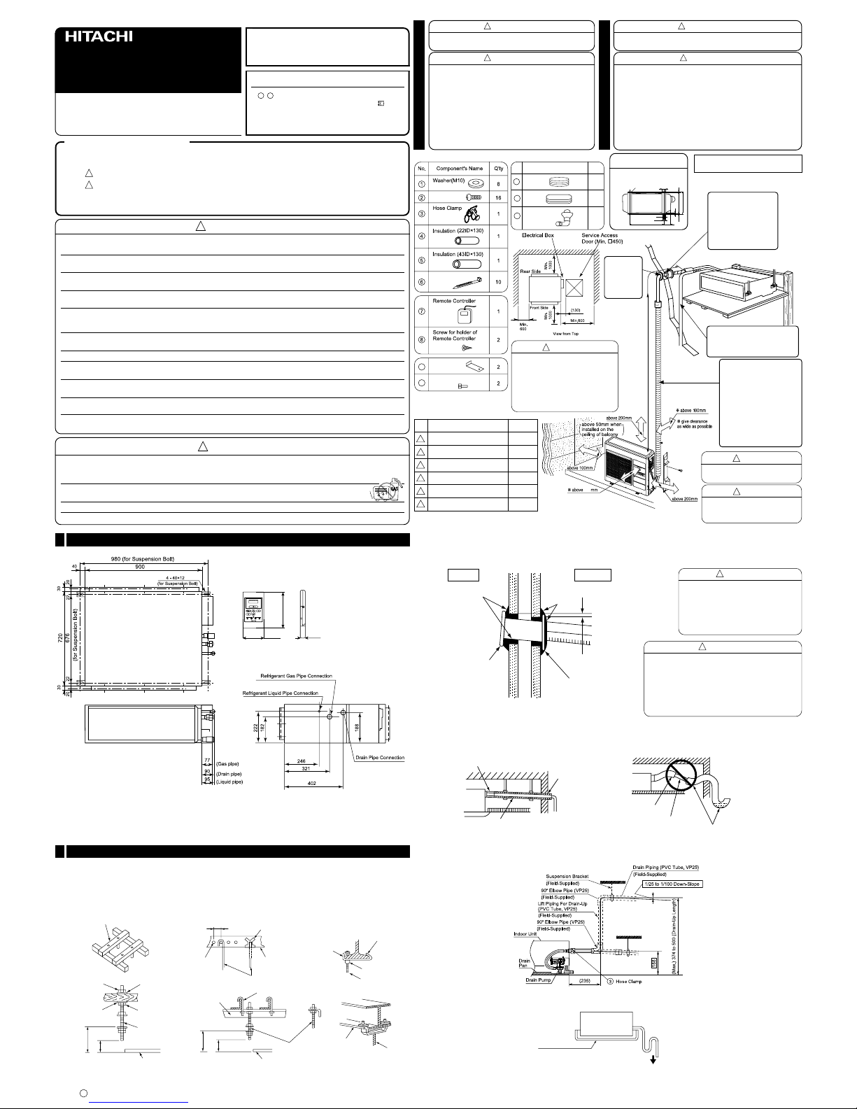
Accessories to indoor Unit:
Other optional parts for display
panel & wireless remote control
SPX-RCK2
9
Filter Holder
Screw for Filter Holder
10
Screw (4mm)
Binder
Display panel
Panel installation plate
Panel cover
Remote controller (wireless)
Holder for remote control
3.1 x 16 screw
Item QuantityNo.
1
2
3
4
5
6
1
1
1
1
1
2
●
Install the indoor unit with a proper
clearance around it for operation
and maintenance working space.
●
In case that the ceiling board can
not be detected for servicing,
prepare a service access door
below the indoor unit for removing
the indoor unit.
Dimension of Mounting Stand
of the outdoor unit
3
Bush
Names of Outdoor Components
QtyNo. Item
Drain Pipe
1
11
12
Bush
1
13
Figure showing the Installation
of Indoor and Outdoor Unit.
CAUTION
!
CAUTION
Always install the indoor unit level.
Units not installed level may leak.
!
The indoor piping
should be insulated
with the enclosed
insulation pipe. (If the
insulator is insufficient,
please use commercial
producrts.)
CAUTION
●
Discharge grille and suction grille
shall be covered by insulation
material to prevent water drop.
!
●
The difference in height
between the indoor and
outdoor unit should be
kept below 20m.
●
The connecting pipe, no
matter big or small, should
all be insulated with
insulation pipe and then
wrapped with vinyl tape.
(The insulator will
deteriorate if it is not
wrapped with tape).
Unit : mm
Wired remote controller
120
70 18
●
Need a connecting work for refrigerant pipe, drain pipe and F cable in the ceilling after suspending the indoor unit. Arrange
drain pipe, refrigerant pipe and F cable in their installation position.
●
For finishing of opening on ceiling, arrange with builder in detail.
●
If ceilling is already completed, connecting cables between indoor and outdoor, piping and drain piping must be done before
fitting indoor unit.
Opening on ceiling & suspension bolt
1
Wall Penetration and Installation of Protection Pipe
●
Drill a ø 65mm hole on wall which is slightly tilted towards the outdoor side. Drill the wall at a small angle.
●
Cut the protection pipe according to the wall thickness.
●
Empty gap in the sleeve of protection pipe should be completely sealed with putty to avoid dripping of rain water into the room.
Be sure that the wire is not in contact
with any metal in the wall. Please use
the protection pipe as wire passing
through the hollow part of the wall so as
to prevent the possibility of damaged
by mouse.
Preparation for installing indoor unit
2
Installation of suspension bolts
●
Be sure to reinforce furring of ceiling (frame : ceiling joints and supporter) to maintain level of ceiling and prevent vibration
of ceiling plate.
●
Suspension bolts should be purchased in the field.
●
Refer to diagrams shown below for length of suspension bolts.
●
In case of wooden frame●In case of steel frame (Unit : mm)
Be sure to use protection pipe (commercial product).
If connecting cables are touching metal lath inside
the wall or inside the wall is hollow where mouse
can bite cables, it can cause electrical shock or fire.
If sealing is not complete, high humidity air from
inside the wall or outside of the room can come in
and cause water dripping.
60 ~ 90mm square piece of lumber
150 ~ 160mm
Insert 980 ~ 1470N
(100 ~ 150kgf)
Bend slippreventive metal
C type
metal
Concrete
Suspension bolt (M10)
Hanger bolt
Reinforcing
bar
Long nut
Suspension
bolt (M10)
Suspension
bolt (M10)
Angle
Nut
Suspension
bolt (M10)
Suspension
bolt (M10)
Ceiling
Ceiling
H beam
Nut
Angle
110
110
About 75
Angle
About 75
Indoor Outdoor
Seal with putty
Seal with
putty
2 ~ 5mm
Sleeve of
protection
pipe
WALL
Protection
pipe
●
In case drain piping cannot be done smoothly due to obstacles, it can also be arranged outside of the main unit as shown in the drawing
below.
●
Maximum drain-up length shall not more than 500mm height.
●
When the relative humidity of inlet or ambient air exceeds 80%, apply an (field-supplied) auxiliary drain pan beneath the indoor unit as
shown below
Auxiliary Drain Pan
To the Atmosphere
(Field-Supplied)
Drain pipe installation
●
Prepare polyvinyl chloride pipe with a 32mm outer diameter.
●
Be sure to roll an insulation (thickness 10mm or more) for the drain pipe at indoor side.
●
Always draw the drain pipe downward so that water flows smoothly. Fix it (ex. by hanger) to prevent a peak and trap.
Downward 1/25 ~ 1/100
Seal
Insulation (Thickness
10mm or more)
Trap
No insulation
Stagnant
water
57
12
35
198
508
320
10
20
(10)
340
(unit : mm)
mounting stand
!
WARNING
!
CAUTION
Installation of Indoor Unit
3
Marking of the Positions of the Sling bolts and Piping Connections
1.Mark the positions of the sling bolts, refrigerant piping connections and drain connection.
2.Ceiling Work: it basically varies according to the building structure.
Consult with the architect or interior finish worker for more information on this.
(a) To maintain the appropriate levelness of the ceiling and preventing from the vibration, the additional reinforcement in the
ground of ceiling (Building Frame) is essential.
Also, rubber cushion can be applied for the insufficient strength of the frame around the sling part on the ceiling.
(b) Provide a space for the air inlet grille, air outlet grille and maintenance work.
(c) Do not suspend the indoor unit and electric light units from the same auxiliary supporting beams, and do not connect the
suspension bolts on the indoor units. If connected, the light may flicker or the light unit may be rattled by vibration of the indoor
units.
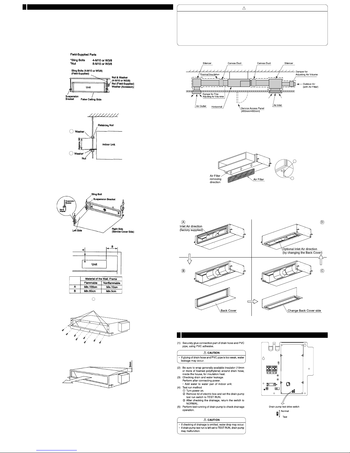
Mounting the indoor unit
Hanging indoor unit.
1.How to put Nuts or Sling Bolts
Put nuts on each of the four hanging bolts.
2.Hanging the Indoor unit
●
Hook suspension bracket to the nut and washer of each hanging bolt, as shown, starting
at the opposite side to service cover side.
●
After checking that the nut and washer are correctly fixed by the retainers of the suspension bracket, hook the suspension bracket
of the service cover side to the nut and washer. (Put the sling bolts away from the unit when hooking.)
●
Piping and wiring work will be required in the ceiling after hanging the unit. Therefore, determine the drawing direction of pipe after
selecting the installation location, particularly if the ceiling was existed.
piping and wiring work should be carried out up to the connecting positions before hanging the unit.
3.For reasons of the disaster prevention, the distance between under the roof and wall surface should be followed as shown in the
below figure.
●
Use the nonflammable material for the duct.
●
Select the indoor unit position, fixing direction of air outlet so that cool/hot air reaches all the room. Standard position of the indoor
unit is with the wall side on the ceiling.
●
Remove the factory fitted filter and filter holders before installing of full duct type.
9
10
Inlet air direction change instructions
Connecting Return Duct and Supply Duct
1.The return duct should be connected with the indoor through canvas ducts between inlet side of the indoor unit and ceiling of
the room. The supply duct should be connected with the indoor unit through canvas ducts, in order to avoid abnormal sound
vibration. The unit is equipped with a pre-drilled duct flange for the return and supply duct connection.
2.Attach the vibration proof rubber to Sling Bolt in order to avoid abnormal sound vibration.
3.Undamped natural frequency is 9 to 21 Hz.
4.Duct material should be non-flammable material.
5.Perform the heat insulation work over the duct and the duct flange for dew protection.
●
If a lower sound level is further required, install silencer (field-supplied).
●
The facility design should be “Unit External static Pressure = Duct Pressure Loss Suction / Discharge Loss”. If the duct
pressure loss becomes under to the unit external static pressure, air speed will get larger and lead to the occurrence of louder
noise, splashing water and activation of motor protection circuit, and if the unit external static pressure becomes under to the
duct pressure loss, some problems such as inability to change the air speed may occur. Set the airflow control damper or
shift the static pressure control switch to adjust to get almost equal level between the external static pressure and the duct
pressure loss. (See “Setting of External Pressure” section for the details.)
●
Basically this unit is designed to install the ducts on the inlet side and the outlet side.
Ask for more information for using the return ducts in the ceiling.
Adjusting of the Unit Level
1.Check to ensure that the foundation is flat, taking into account the maximum foundation gradient.
If not, it will occur malfunction of float switch or not operation. Then it will drop the drain water from the ceiling.
2.The unit should be installed so that the rear side of the unit is slightly (0mm to 5mm) lower than the front side, in order to avoid
the incorrect position of the drain discharge.
3.Tighten the bolts of the sling nuts with the suspension brackets after adjustment is completed. Special plastic paint must be applied
to the bolts in order to prevent them from loosening.
Keep the unit as well as relevant equipment covered with the vinyl cover during installation work.
Connection of drain pipe
4
‚O‚O‚T‚P‚Q‚S‚`
CAUTION
!
1
1
4.If decided to keep the flange at discharge side, fix screw 2 at 8 positions. However, if decided not to keep the flange, remove
4 screws that fixed to the flange.
Fix in factory
 Loading...