

Page 1

PLASMA TELEVISION
Operating Guide for P50X901 and
IMPORTANT SAFETY INSTRUCTIONS....................................................................................... 2-3
FIRST TIME USE .........................................................................................................................4-25
THE REMOTE CONTROL....................................................................................................... 26-43
ON-SCREEN DISPLAY ............................................................................................................ 44-81
USEFUL INFORMATION.......................................................................................................... 82-89
END USER LICENSE AGREEMENT FOR HITACHI DTV SOFTWARE.............................. 180-188
APPENDIXES.........................................................................................................................189-190
INDEX............................................................................................................................................191
Page 2
Important Safety Instructions
SAFETY POINTS YOU SHOULD KNOW ABOUT
YOUR HITACHI PLASMA TELEVISION
Our reputation has been built on the quality,
performance, and ease of service of HITACHI plasma
televisions.
Safety is also foremost in our minds in the design of
these units. To help you operate these products
properly, this section illustrates safety tips which will be
of benefit to you. Please read it carefully and apply the
knowledge you obtain from it to the proper operation of
your HITACHI plasma television.
Please fill out your warranty card and mail it to
HITACHI. This will enable HITACHI to notify you
promptly in the improbable event that a safety problem
should be discovered in your product model.
Follow all warnings and instructions marked on
this plasma television.
The lightning flash with arrowhead symbol,
within an equilateral triangle, is intended
to alert the user to the presence of
uninsulated “dangerous voltage” within the
product’s enclosure that may be of a sufficient
magnitude to constitute a risk of electric shock to a
person.
The exclamation point within an equilateral
triangle, is intended to alert the user to the
presence of important operating and
maintenance (servicing) instructions in the
literature accompanying the appliance.
READ BEFORE OPERATING EQUIPMENT
Follow all warnings and instructions marked on this
plasma television.
1. Read these instructions.
2. Keep these instructions.
3. Heed all warnings.
4. Follow all instructions.
5. Do not use this apparatus near water.
6. Clean only with a dry cloth.
7. Do not block any ventilation openings. Install in
accordance with the manufacturer’s instructions.
8. Do not install near any heat sources such as
radiators, heat registers, stoves, or other apparatus
(including amplifiers) that produce heat.
9. Do not defeat the safety purpose of the polarized or
grounding-type plug. A polarized plug has two
2
blades with one wider than the other. A grounding
type plug has two blades and a third grounding
prong. The wide blade or the third prong are
provided for your safety. If the provided plug does
not fit into your outlet, consult an electrician for
replacement of the obsolete outlet.
10. Protect the power cord from being walked on or
pinched particularly at plugs, convenience
receptacles, and the point where they exit from the
apparatus.
11. Only use the attachments/accessories specified by
the manufacturer.
12. Use only with the cart, stand, tripod,
bracket, or table specified by the
manufacturer, or sold with the
apparatus. When a cart is used, use
caution when moving the cart/apparatus
combination to avoid injury from tip-over.
13.
Unplug this apparatus during lightning storms or
when unused for long periods of time.
14. Refer all servicing to qualified service personnel.
Servicing is required when the apparatus has been
damaged in any way, such as power-supply cord or
plug is damaged, liquid has been spilled or objects
have fallen into apparatus, the apparatus has been
exposed to rain or moisture, does not operate
normally, or has been dropped.
15.Televisions are designed to comply with the
recommended safety standards for tilt and stability.
Do not apply excessive pulling force to the front, or
top, of the cabinet which could cause the product
to overturn resulting in product damage and/or
personal injury.
16.Follow instructions for wall, shelf or ceiling
mounting as recommended by the manufacturer.
17. An outdoor antenna should not be located in the
vicinity of overhead power lines or other electrical
circuits.
18. If an outside antenna is connected to the receiver
be sure the antenna system is grounded so as to
provide some protection against voltage surges and
built up static charges. Section 810 of the National
Electric Code, ANSI/NFPA No. 70-1984, provides
information with respect to proper grounding for the
mast and supporting structure, grounding of the
lead-in wire to an antenna discharge unit, size of
grounding connectors, location of antenna discharge
unit, connection to grounding electrodes and
requirements for the grounding electrode.
Note to the CATV system installer: This reminder is
provided to call the CATV system installer’s attention to
Article 820-44 of the NEC that provides guidelines for
proper grounding and, in particular, specifies that the
cable ground shall be connected to the grounding
system of the building, as close to the point of cable
entry as practical.
Page 3
Important Safety Instructions
Power source
This plasma television is designed to operate on 120
volts 60 Hz, AC current. Insert the power cord into a
120 volt 60 Hz outlet. The mains plug is used as the
disconnect device and shall remain readily operable.
To prevent electric shock, do not use the plasma
television’s (polarized) plug with an extension cord,
receptacle, or other outlet unless the blades and
ground terminal can be fully inserted to prevent blade
exposure.
Never connect the plasma television to 50 Hz, direct
current, or anything other than the specified voltage.
Caution
Never remove the back cover of the
plasma television as this can expose you
to very high voltages and other hazards. If
the television does not operate properly,
unplug the plasma television and call your authorized
dealer or service center.
Caution
Adjust only those controls that are covered in the
instructions, as improper changes or modifications not
expressly approved by HITACHI could void the user’s
warranty.
Warning
• To reduce the risk of fire or electric shock, do not
expose this apparatus to rain or moisture.
• The plasma television should not be exposed to
dripping or splashing and objects filled with liquids,
such as vases, should not be placed on the
television.
• This apparatus shall be connected to a mains
socket outlet with a protective earthing connection.
Public viewing of copyrighted material
Public viewing of programs broadcast by TV stations
and cable companies, as well as programs from other
sources, may require prior authorization from the
broadcaster or owner of the video program material.
This product incorporates copyright protection
technology that is protected by U.S. patents and other
intellectual property rights. Use of this copyright
protection technology must be authorized by Macrovision,
and is intended for home and other limited pay-per-view
uses only unless otherwise authorized by Macrovision.
Reverse engineering or disassembly is prohibited.
Note
This digital television is capable of receiving analog
basic, digital basic and digital premium cable television
programming by direct connection to a cable system
providing such programming. A CableCARD provided
by your cable operator is required to view encrypted
digital programming. Certain advanced and interactive
digital cable services such as video-on-demand, a cable
operator’s enhanced program guide and data-enhanced
television services may require the use of a set-top box.
For more information call your local cable company.
Note
• There are no user serviceable parts inside the
plasma television.
• Model and serial numbers are indicated on back side
and right side of the plasma television.
Prevention of screen damages
Continuous on-screen displays such as video games,
stock market quotations, computer generated graphics,
and other fixed (non-moving) patterns can be
permanently imprinted onto your TV screen. Such
“SCREEN DAMAGES” constitute misuse and are NOT
COVERED by your HITACHI Factory Warranty.
If still images are left on the screen for more than 2.5
minutes, protection function will work automatically so that
contrast reduces to minimize image retention on plasma
display panel.
Please note that this is not a malfunction but it helps to
minimize image retention.
The original contrast will restore after moving images are
displayed for about 6 minutes. Original contrast can be
restored quickly by turning power On/Off with remote
control or power switch on unit.
Lead Notice
This product contains lead. Dispose of this product in
accordance with applicable environmental laws. For
product recycling and disposal information, contact your
local government agency or www.eRecycle.org
(in California), the Electronic Industries Alliance at
www.eiae.org (in the US) or the Electronic Product
Stewardship Canada at www.epsc.ca (in Canada).
FOR MORE INFORMATION, CALL 1-800-HITACHI.
3
Page 4
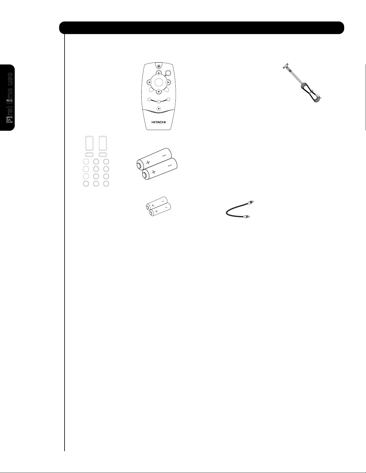
Accessories
Power Cord
Remote Control
Two “AA” size,
1.5V batteries
2 IR Blaster Cables
Power Swivel Table Top Stand
(P50X901 model only)
For U.S. models: For optional accessories, please access our web site at: www.hitachi.us/tv
CANADA only: For optional accessories, please access our web site at: www.hitachi.ca/tv
Power Swivel Cable
Two “AAA” size,
1.5V batteries
MUTE
FAV CH
SELECT
VOL +
CH -
CH +
GUIDE
VOL -
MENU
INPUTS
POWER
EXIT
Simple Remote
.
쐄
쐃
쐋
쐊
쐆
쐇 쐂
쐎
쐏
First time use
Check to make sure you have the following accessories before disposing of the packing material.
4
Page 5
How To Set Up Your New Hitachi Plasma Television
To take measures to prevent the Plasma Television from tipping over and prevent possible injury
it is important to mount the unit in a stable and flat surface.
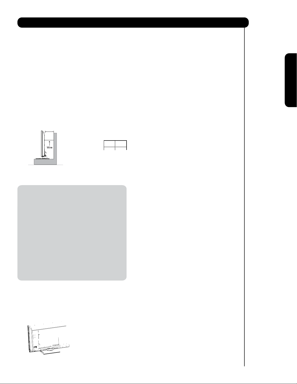
Securing to a Wall
1. Using metallic wire (two places) fasten the set to
the clamping screw on the rear of the Plasma
TV as shown below.
Wire
2. Keep the Plasma television 4 inches away from the
wall except when mounted using the wall mount
bracket.
3. Secure the television to the wall as shown.
A
A B
50"
4 in.
10 cm
12 in.
30 cm
* Please adjust the wire length to avoid touching
the wall when turning the
TV (P50X901 only).
NOTES: 1. Do not block the ventilation holes of the
Plasma Television. Blocking the ventilation
holes might cause fire or defect.
2. In case of an abnormal symptom, unplug
the AC cord.
3. If you purchased the wall mount bracket
option, please ask for professional installer.
Do not install by yourself.
4. Install the unit at a proper area where it does
not expose anyone to any danger of hitting
themselves (for example their hands, head
or face, etc.) against the edge of the unit and
cause personal injury.
Caution when moving the main unit
As this product is heavy, whenever it is moved, two
people are required to transport it safely. Whenever the
unit is moved it should be lifted forward using the top
and base on both sides of the Television for stability.
When moving the Television, lift the handles , then
support the top frame as shown below.
5
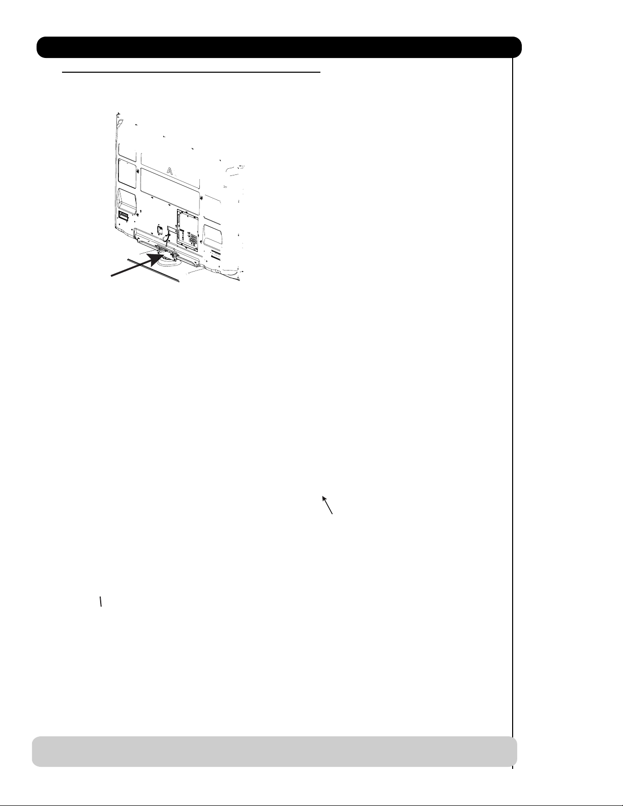
Page 6
쐃
Pass the AC cord through Clamp #1 and connect
쐇
The AC cord, power swivel cable and the signal
cables can all be held together with Clamp #2
(included on the accesories bag).
쐃
6
Page 7
SETTING FOR WALL MOUNTING FOR P50X901 & P60X901
STEP (1) :
Please locate the STAND METAL(50") or METAL POST(60") on the back of the TV . This metal is use to hold the TV and
the Base; so it needs to remove 4 screws from the STAND base in order to separate the TV from the Base.
STAND METAL
STEP (2):
lease remove the 4 screws of the STAND metal or metal POST from the TV, now the TV STAND can be separated
P
from the TV. For dimensions of the WALL MOUNT assembly please refer to page
86 & 87.
TV STAND BASE
STAND METAL
SCREWS
4
NOTE: Use the specified WALL MOUNT unit for the Plasma TV depending on the size of your TV.
Please access our web site at: www.hitachi.us/tv for recommended accessories for your tv.
7
Page 8
How to set up your new HITACHI Plasma Television
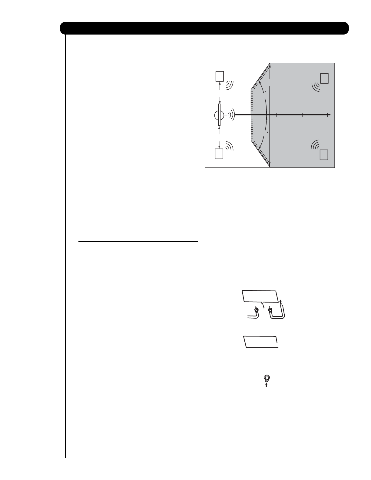
VIEWING
T
he best picture is seen by sitting directly in front of
the TV and about 10 to 18 feet from the screen.
During daylight hours, reflections from outside light
may appear on the screen. If so, drapes or screens
can be used to reduce the reflection or the TV can
be located in a different section of the room.
If the TV’s audio output will be connected to a Hi-Fi
system’s external speakers, the best audio
performance will be obtained by placing the
speakers equidistant from each side of the receiver
cabinet and as close as possible to the height of
the picture screen center. For best stereo
separation, place the external speakers at least
four feet from the side of the TV, place the surround
speakers to the side or behind the viewing area.
Differences in room sizes and acoustical
environments will require some experimentation
with speaker placement for best performance.
ANTENNA CONNECTIONS TO REAR JACK
PANEL
R
4" Minimum
4" Minimum
L
S
70
BEST
HORIZONTAL
5'
10'
VIEWING ANGLE
70
15' 20'
S
VHF (75-Ohm) antenna/CATV (Cable TV)
When using a 75-Ohm coaxial cable system, connect CATV coaxial cable to the AIR/CABLE (75-Ohm) terminal.
Or if you have an antenna, connect the coaxial cable to the same AIR/CABLE terminal.
VHF (300-Ohm) antenna/UHF antenna
When using a 300-Ohm twin lead from an outdoor
antenna, connect the VHF or UHF antenna leads to
screws of the VHF or UHF adapter. Plug the adapter
into the antenna terminal on the TV.
When both VHF and UHF antennas are
connected
Attach an optional antenna cable mixer to the TV
antenna terminal, and connect the cables to the
antenna mixer. Consult your dealer or service store for
the antenna mixer.
8
Page 9
How to set up your new HITACHI Plasma Television
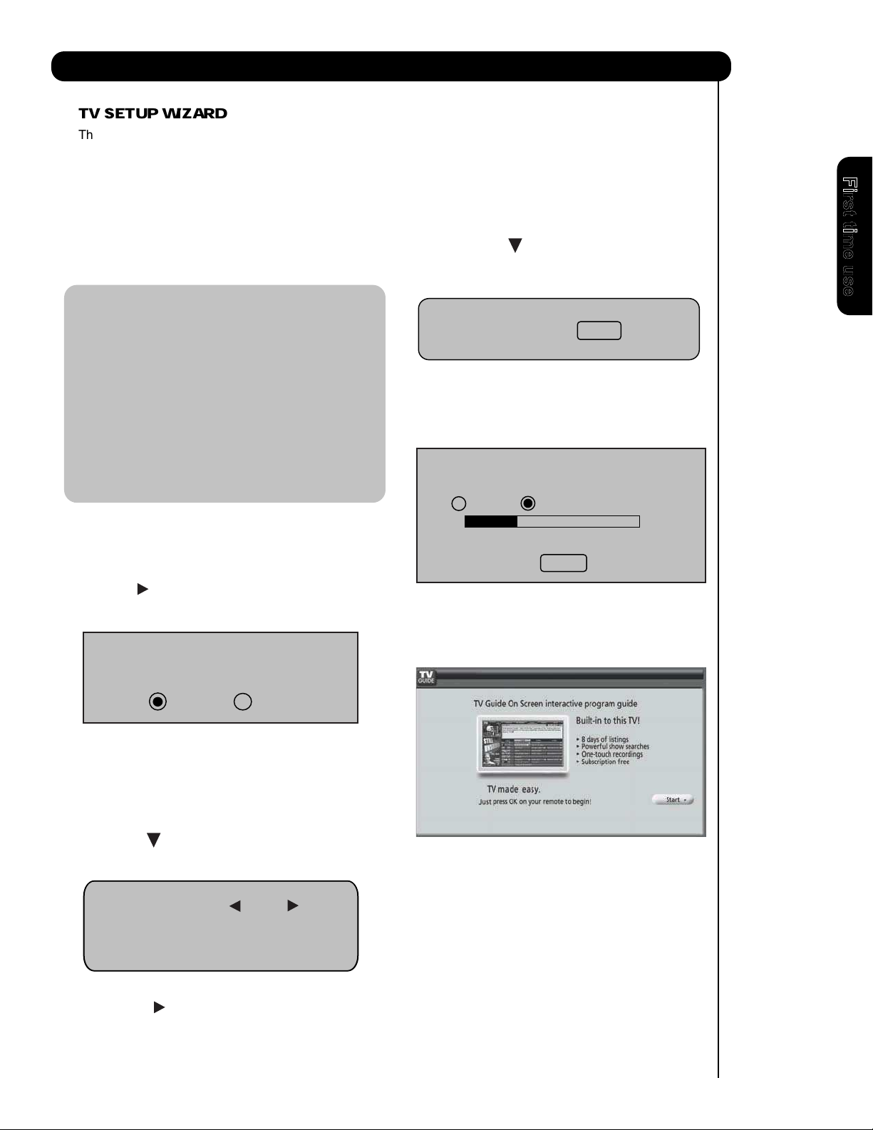
TV SETUP WIZARD
This television has a TV Guide On ScreenTM feature which has the ability to show you a customized list of the
programs and channels available in your area. The information for the guide is broadcast on different channels
in different areas.
Please use this TV Setup Wizard to help the TV Guide On Screen
your area.
TM
find the channels with the information for
First time use
The TV Setup Wizard automatically starts the first
time the TV is turned on.
Note:
1. If you see this screen when you turn on your TV for
the first time and did not yet connect your external
devices and cables to your TV, turn off your TV,
unplug the power cord and connect your devices
and cables according to the applicable connections in
the“
First Time Use” section of this Operating Guide.
2. After performing TV Setup Wizard operation, this
page will not appear again. For updating and
adding the channels available in your area refer
to the Auto Channel Scan feature on page 57.
If this is the first time you have turned on your TV and the
TV Setup Wizard appear on-screen, start by selecting Yes
or No in the top portion of the TV Setup Wizard.
1. Use the CURSOR to select Yes or No and press the
SELECT button on the remote control.
Do you want the TV to find all of the channels
for the TV Guide On ScreenTM?
4. Press the CURSOR to move to the next
window to start the Auto Channel Scan.
Auto Channel Scan : Start
5. Press the SELECT button on the remote
control to begin scanning.
Air
Scanning Channel Number : 12
Analog Digital 12-123
Scan time may take 10 to 20 minutes
Cancel
When Auto Channel Scan is done the TV Guide On
ScreenTM Setup page will appear (refer to page 54).
Yes No
If Yes is selected proceed to step 2.
If No is selected, press the EXIT button on the remote
control and the TV Guide ON Screen
appear ( refer to page 54).
2. Press the CURSOR to move to the next window to
select the source.
Source: Air
Please connect the antenna or cable
To the input labeled “Air/Cable”.
3. Press the CURSOR to select Air, Cable(1) or
Cable(2).
TM
Setup page will
9
Page 10
10
First time use
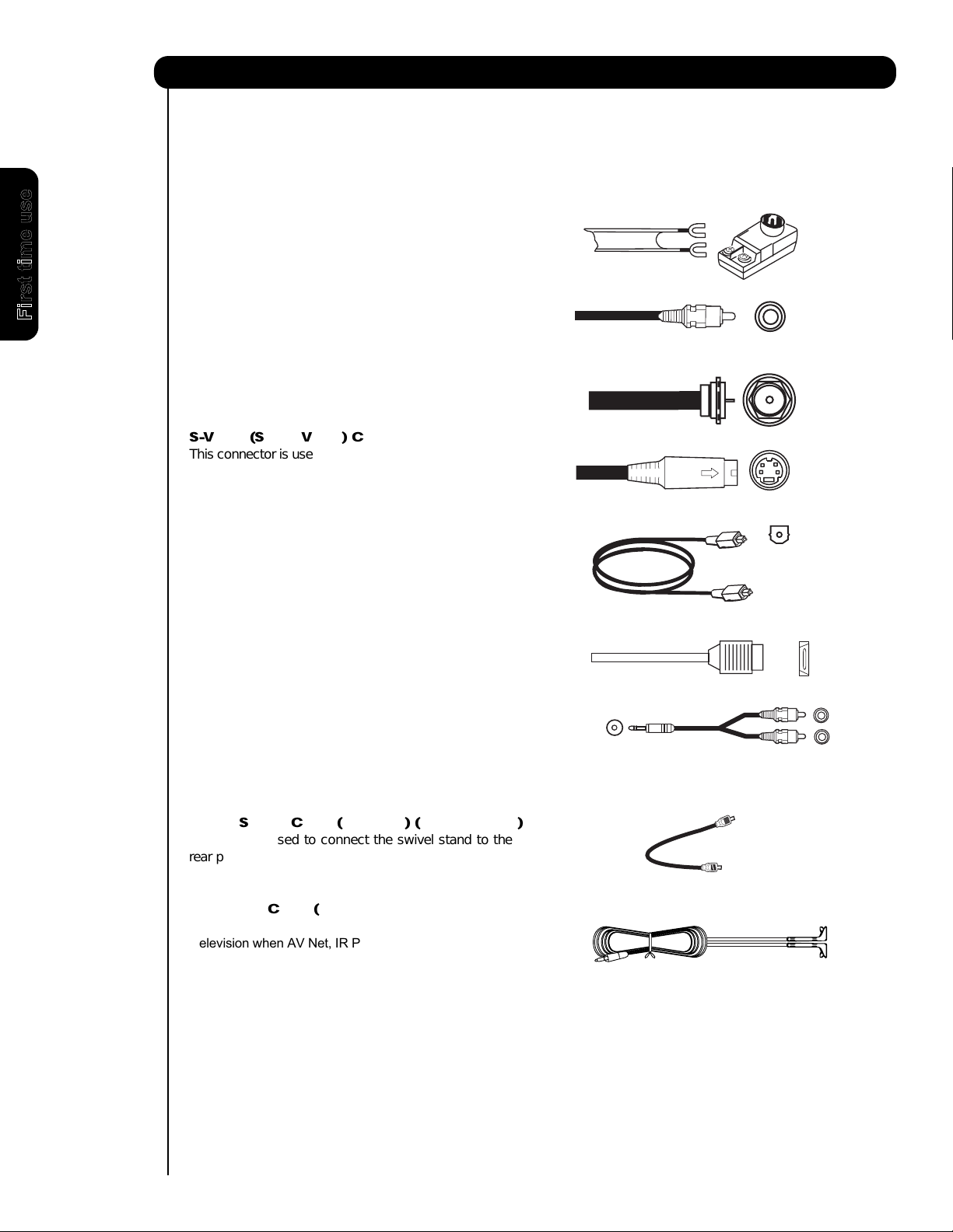
300-Ohm Twin Lead
This outdoor antenna cable must be connected to an
antenna adapter (300-Ohm to 75-Ohm).
Phono or RCA
Used on all standard video and audio cables which
connect to inputs and outputs located on the
television’s rear jack panel and front control panel.
“F” Type 75-Ohm Coaxial Antenna
For connecting RF signals (antenna or cable TV) to the
antenna jack on the television.
S-Video (Super Video) Cable
This connector is used on camcorders, VCRs and laser
disc players with an S-Video feature in place of the
standard video cable to produce a high quality picture.
Optical Cable
This cable is used to connect to an audio amplifier with
an Optical Audio In jack. Use this cable for the best
sound quality.
HDMI Cable
This cable is used to connect your external devices
such as Set-Top-Boxes or DVD players equipped with
an HDMI output connection to the TV’s HDMI input.
Stereo Cable (3.8mm plug to 3.5mm plug)
Used on all standard video and audio cable which
connect to inputs and outputs located on the rear jack
panel and front control panel.
Hook-up Cables and Connectors
Most video/audio connections between components can be made with shielded video and audio cables that have
p
hono connectors. For best performance, video cables should use 75-Ohm coaxial shielded wire. Cables can be
purchased from most stores that sell audio/video products. Below are illustrations and names of common
connectors. Before purchasing any cables, be sure of the output and input connector types required by the
various components and the length of each cable.
AUDIO OUT
3.8mm
STEREO
MINI-PLUG
2
RCA TYPE
PLUGS
Cable
Cable
Power Swivel Cable (Provided) (P50X901 only)
This cable is used to connect the swivel stand to the
rear panel of the Plasma Television.
IR Blaster Cable (Provided)
Connect the IR Blaster to the IR output of your Plasma
Television when AV Net, IR Passthru or G-LINK
TM
feature
are used. You must place the IR Blaster in front
of the corresponding IR window of your cable box
VCR, Set-Top-Box, or other supported equipment.
Page 11
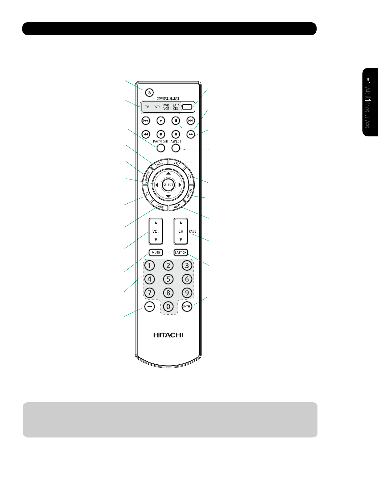
Quick Reference Remote Control Buttons and Functions
In addition to controlling all of the functions on your HITACHI Plasma TV, the new remote control is designed to
operate different types of devices, such as, DVD Players, CBL (Cable Boxes), set-top-boxes, satellite receivers,
and VCRs. The remote control must be programmed to control the chosen device. Please see pages 26
complete description of all features and programming of the Remote Control.
(TV, DVD, SAT/CBL,PVR/VCR)
T
urns the selected device on and o.
Turns on or blinks to show remote control
mode w hen the SO URCE ACCESS buttons
are pressed.
Toggles picture mode settings
between DAY and NIGHT mode.
(TV,DVD,SAT/CBL,PVR/VCR)
Accesses the OSD menu system.
Accesses the INPUTS menu system.
CURSOR PAD/SELECT BUTTON
(TV, DVD, SAT/CBL,PVR/VCR)
The Cursor Pad is used as a cursor to navigate
through the OSD and INPUT menu systems.
The Select button is used to Select/Activate
highlighted menu items.
Closed Caption (CC) BUTTON
Press to show and change the
Closed Caption mode.
Accesses the program guide of TV
Increase up and decrease down to adjust
the audio level of your TV.
Reduces the audio level to 50% if pressed
once, and to complete mute if pressed
twice. Press it a third time to restore audio
level.
Used to manually enter the TV channel, and used
for numeric entry when navigating through the
the OSD, INPUTS.
The (-) button is used when the remote is in
Set-Top-Box (STB) mode or when the TV uses a
digital input.
(TV, DVD, SAT/CBL, PVR/VCR)
POWER BUTTON
MODE INDICATOR
DAY/NIGHT BUTTON
MENU BUTTON
INPUTS BUTTON
GUIDE BUTTON
(TV,
SAT/CBL, PVR)
and other devices.
VOLUME BUTTONS
MUTE BUTTON (TV)
NUMERIC BUTTONS
(TV)
(TV)
(TV)
(TV )
(-) BUTTON
(TV,STB)
SOURCE ACCESS BUTTONS
(TV, DVD, PVR/VCR, SAT/CBL)
Changes the mode of the Universal Remote
Control to control the device selected.
PAUSE BUTTON
(TV, PVR/VCR, DVD)
Press to show and change the Freeze mode of the TV.
Also used to pause other devices when the remote is in
DVD or PVR/VCR.
DVD/VCR CONTROL BUTTONS
(DVD, PVR/VCR)
Controls the functions of your VCR and DVD.
ASPECT BUTTON
(TV)
Changes the aspect ratio of the TV.
EXIT BUTTON
(TV, SAT/CBL, PVR/VCR)
Exits out of the OSD, INPUTS menu
systems if their menu is displayed.
PIP CONTROL BUTTON
(TV)
Press to show and change the Picture-in-Picture mode.
FAVORITE CHANNEL
(FAV CH) button (TV)
Press to enter/access Favorite Channel (FAV CH) mode.
(Favorite channel is only available for TV mode.)
INFO BUTTON
(TV, STB, CBL, PVR)
Displays various information on the
screen, such as channel information.
CHANNEL UP & DOWN BUTTONS
(TV, CBL, STB, PVR/VCR)
Changes up or down the channel.
LAST CHANNEL BUTTON
(TV, SAT/CBL, PVR)
witches between the current and last channel viewed.
S
ENTER BUTTON
(TV, VCR, SAT/CBL)
Press to use as SELECT feature.
-43 for a
First time use
LEGEND
TV – Television PVR – Video Recorder/Player
CBL – Cable Box DVD – Digital Video Disc Player
SAT – Satellite
VCR – Videocassete Recorder
NOTES: 1. The TV’s remote control sensor is located on the right bottom portion of the TV screen. To
control TV functions, please point the remote control directly at the remote control sensor for
best results.
2. VCR precode is included in the PVR mode.
11
Page 12
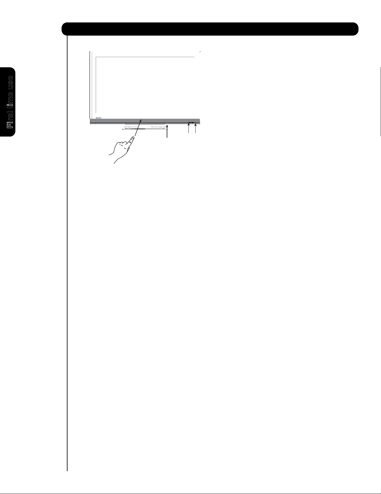
FRONT VIEW (P50X901)
First time use
PUSH TO OPEN
12
For P60X901 model this is not Main Power button,
Page 13
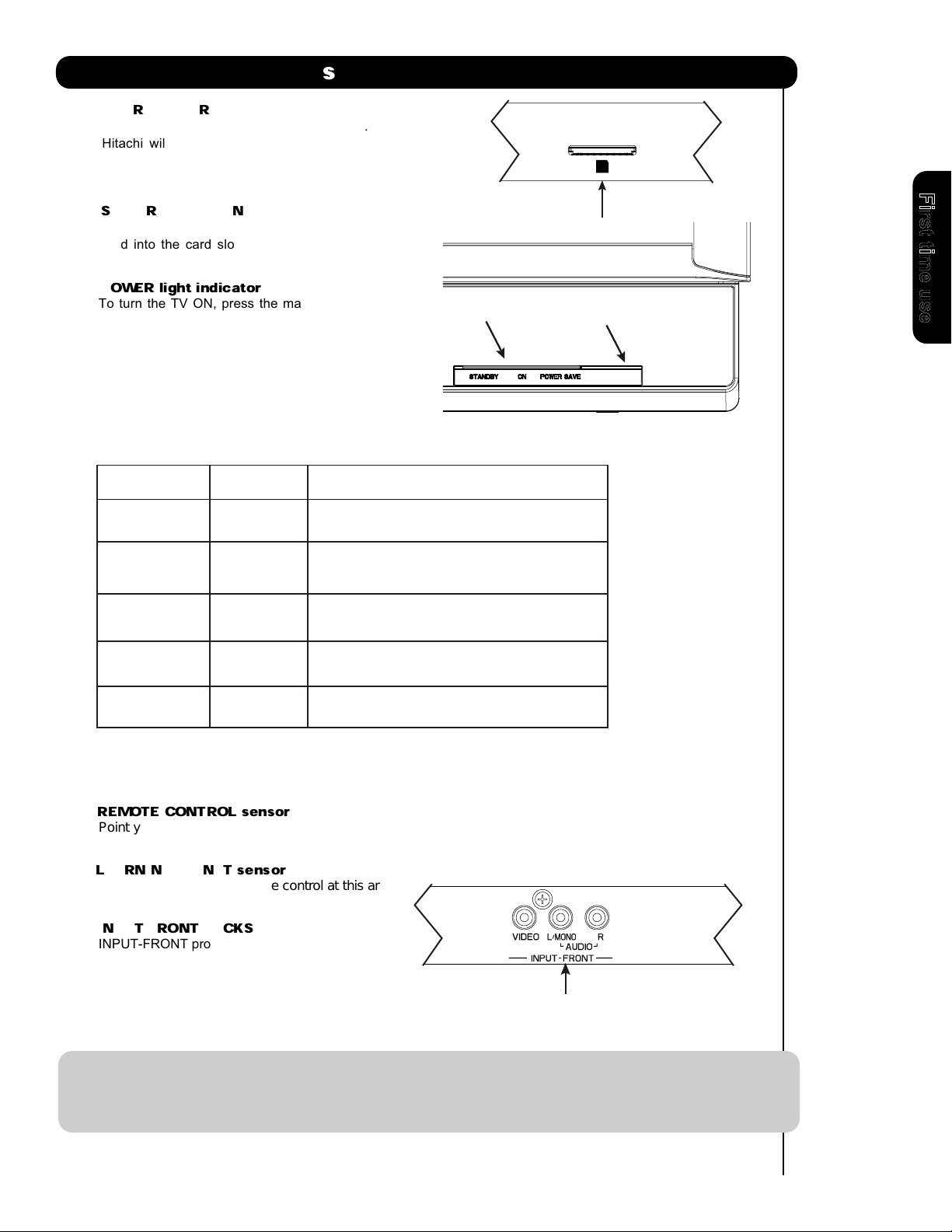
Front Panel Controls
햹
UPGRADE CARD
This card slot is for future software upgrades.
Hitachi will notify you if a software upgrade is
required for your TV. In order to receive written
notification, please complete and return your
warranty card.
햹
SD CARD PHOTO INPUT
To view digital still pictures, please insert a SD
card into the card slot with pictures taken on a
Digital Camera, to view them on the TV screen.
햺
POWER light indicator
To turn the TV ON, press the main power
s
witch located on the lower right side of the
TV. A red stand-by indicator lamp located on
the lower right corner of the front bezel will
illuminate. The Plasma TV is now ready for
remote ON/OFF operation.
Indicating Lamp Power Status Operating
OFF
Off *
. When the main power switch is set to Off.
PHOTO INPUT
PUSH EJECT
햹
햺 햻
Indicating Lamp
R/C, AV Net Sensor
First time use
Lights
Red
Lights
Blue
Lights
Orange
Blinking
Blue
* The Main Power switch applies only for P50X901 model ; so for the P60X901 the
condition for the Indicating Lamp when is OFF , it means that the AC power cord
is unplugged.
햻
REMOTE CONTROL sensor
Point your remote at this area when selecting
channels, adjusting volume, etc.
LEARNING AV NET sensor
햻
Point your equipment’s remote control at this area
while using the AV NET Learning Wizard.
INPUT-FRONT JACKS
햽
INPUT-FRONT provide composite Video jacks for
connecting equipment with this capability,
such as a DVD player or Camcorders.
OFF.
(Stand-by)
On
Off
(Power Saving)
On
When the main power switch on the TV is ON.
TV POWER is ON ; picture is shown.
TV POWER is ON with no signal input
except antenna (no sync. signal).
When TV receives the IR signal from R/C.
햽
NOTES: 1. Your HITACHI Plasma TV will appear to be turned OFF (lights orange) if there is no video input
when INPUT : 1, 2, 3, Front or HDMI : 1, 2, Front is selected. Check the Power Light to make sure
the TV is turned off or in Stand-by mode (lights red) when not in use.
2. Remote Control cannot turn ON/OFF the “MAIN POWER” of the TV.
13
Page 14
First time use
14
Page 15
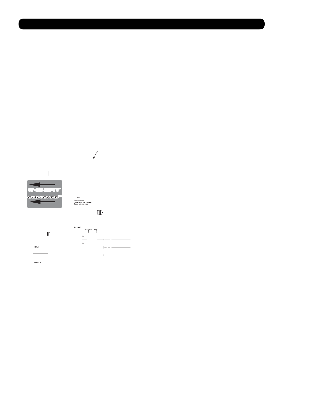
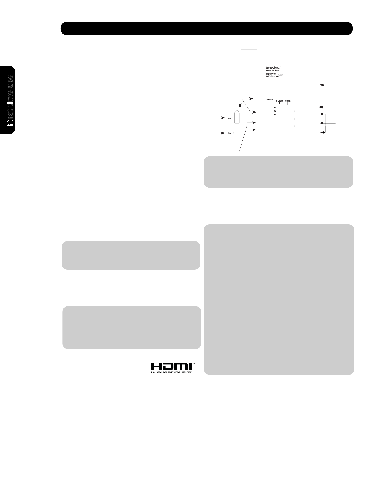
Rear Panel Connections
(POD) module).
Digital Cable Signal
INSERTINSERT
15
Page 16
The FRONT panel jacks are provided as a convenience to allow you to easily connect HDMI or DVI signals
from a DVD, Set Top Box , Video Game as shown in the following examples (When connecting DVI signal it will
First time use
16
OUTPUT
L R
Page 17
Connecting External Video Sources
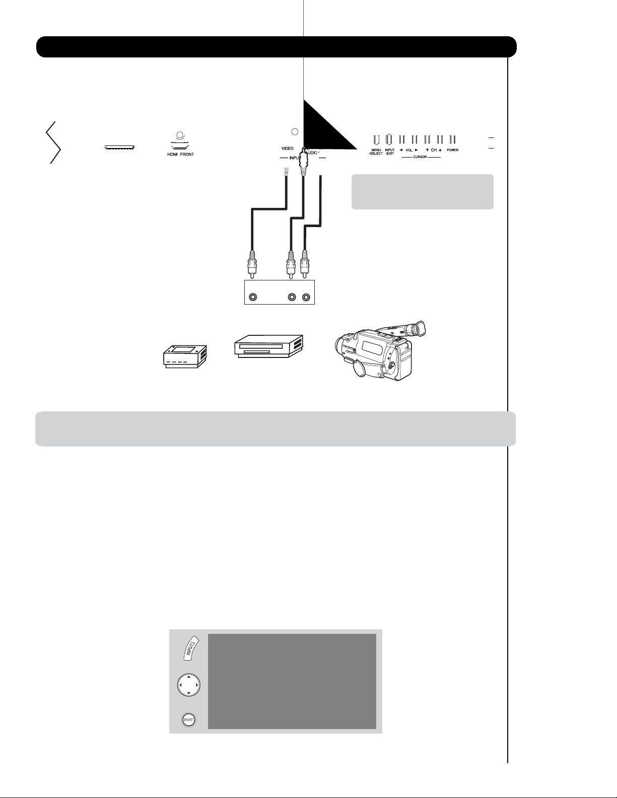
The FRONT panel jacks are provided as a convenience to allow you to easily connect a camcorder , DVD, Video
Game and a VCR as shown in the following examples:
FRONT INPUT PANEL
Note : For Monoaural devices, please
connect Audio signal cable into
L/Mono input jack .
COMPOSITE VIDEO
Video Game
OUTPUT CAPABILITY
DVD , Video Game
Console.
Video Camera
NOTE: 1. Completely insert connection cord plugs when connecting to front panel jacks. If you do not, the
played back picture may be abnormal.
17
Page 18
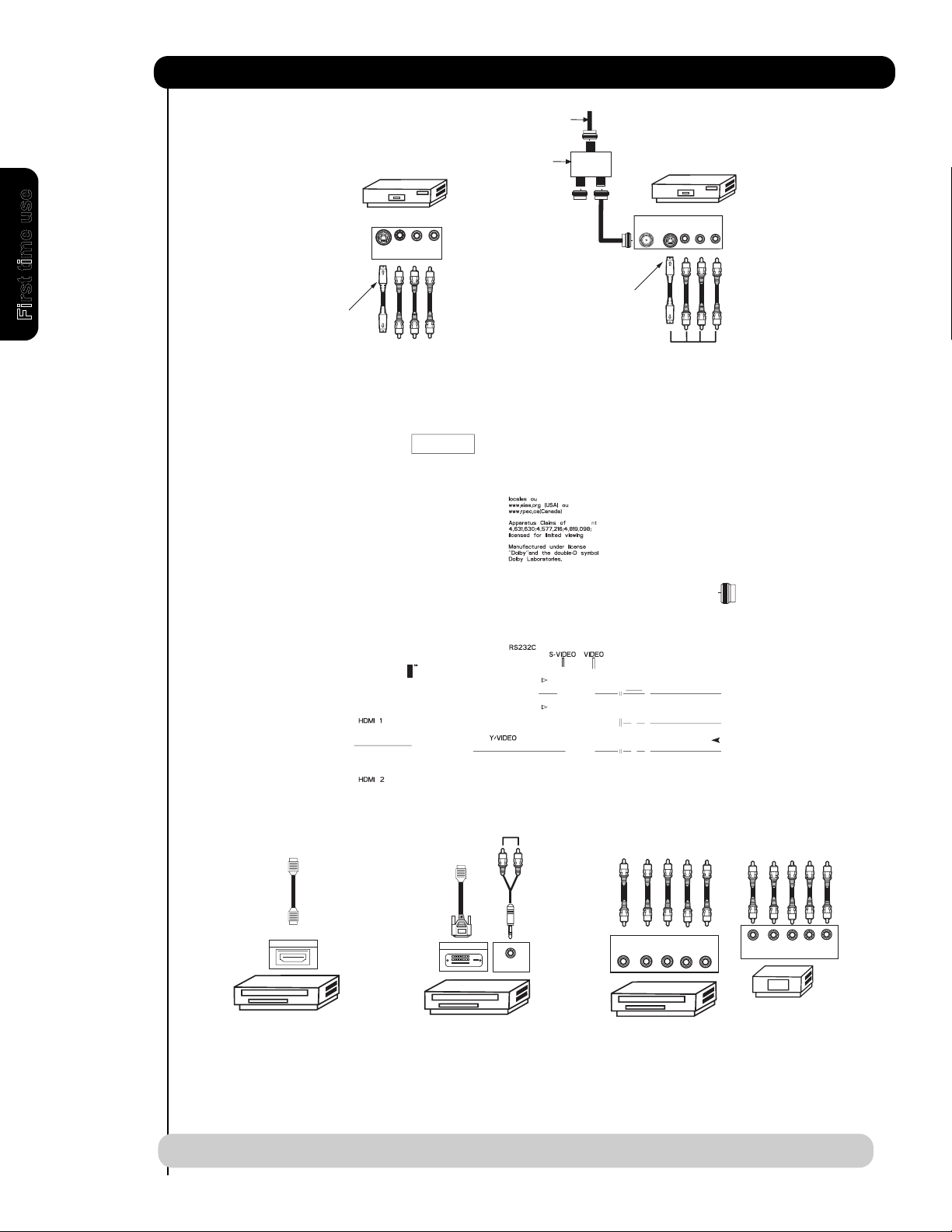
Rear Panel Connections
Outside Antenna
or
Cable TV coaxial cable
2-Way signal splitter
VCR #1
OUTPUT
ANT
IN
V L R
S-VIDEO
S-VIDEO
VCR #2
V L R
INPUT
Optional
First time use
Optional
18
HDMI
to
HDMI
HDMI OUTPUT
HDMI DIGITAL
OUTPUT CAPABILITY
DVI
to
HDMI
DIGITAL OUTPUT
DIGITAL
UTPUT CAPABILITY
O
AUDIO OUT
NOTE: Cables are optional, except when specified.
OUTPUT
Y PB/CBPR/C
DVD Player
L R
R
Y PBP
OUTPUT
R
L R
HDTV Set-Top Box
Page 19

Tips on Rear Panel Connections
• S-VIDEO, Y-PBPR, or HDMI connections are provided for high performance laserdisc players, VCRs etc. that
have this feature. Use these connections in place of the standard video connection if your device has this
feature.
• If your device has only one audio output (mono sound), connect it to the left audio jack on (L/(MONO)) the
Rear Panel.
• Refer to the operating guide of your other electronic equipment for additional information on connecting
your hook-up cables.
• A single VCR can be used for VCR #1 and VCR #2, but note that a VCR cannot record its own video or line
output (INPUT: 1 in the example on page 18). Refer to your VCR operating guide for more information on
line input-output connections.
• Connect only 1 component (VCR, DVD player, camcorder, etc.) to each input jack.
• COMPONENT: Y-P
DVD players and set-top-boxes. Use these connections in place of the standard video connection if your
device has this feature.
• Your component outputs may be labeled Y, B-Y, and R-Y. In this case, connect the components B-Y
output to the TV’s PBinput and the components R-Y output to the TV’s PRinput.
• Your component outputs may be labeled Y-CBCR. In this case, connect the components CBoutput to the
TV’s PBinput and the components CRoutput to the TV’s PRinput.
• It may be necessary to adjust TINT to obtain optimum picture quality when using the Y-PBPRinputs. (See
page 46).
• To ensure no copyright infringement, the MONITOR OUT output will be abnormal, when using the Y-PBPR and
HDMI input jacks.
• Input HDMI 1, HDMI 2 or HDMI FRONT can accept HDMI signal.
(Input 2 & 3) connections are provided for high performance components, such as
BPR
First time use
• S-VIDEO monitor output may be used for recording only when the input is of S-VIDEO type.
• When using a HDMI input from a Set-Top-Box, it is recommended to use a 1080p, 1080i or 720p input signal.
• When HDMI input a 1080p signal, it is recommended that the length of the cable should be less than 5 meters.
INSTALLATION RECOMMENDATION:
1. Video signals fed through a VCR may be affected by copyright protection systems and the picture will be
distorted on the television.
2. Connecting the television directly to the Audio /Video output of a Set-Top-Box will assure a more normal
picture.
19
Page 20
First time use
Back of
VCR
Video
VCR
OUTPUT
20
Page 21

Connecting External Video Sources
CONNECTING A COMPONENT SOURCE WITH HDMI OR
DVI CAPABILITY TO HDMI 1, HDMI 2 OR HDMI FRONT
1. Connect the HDMI or DVI to HDMI connection
cable from the output of the HDTV set top box
or DVD player to the HDMI input as shown
on the Rear panel below.
2. With DVI output, connect the cable from the
AUDIO OUT R of the HDTV set top box or DVD
player to the INPUT (AUDIO/R) jack as shown on
the Rear Panel below.
3. With DVI output, connect the cable from the
AUDIO OUT L of the HDTV set top box or DVD
player to the INPUT (AUDIO/L) jack as shown
on the Rear Panel below.
4. Press the INPUTS button, then select HDMI 1, 2
or FRONT to view the program from the HDTV
SET TOP BOX or DVD player.
5. Select CABLE or AIR from the INPUTS menu to
return to the last channel viewed.
HDMI input
NOTE: 1
. Completely insert the connection cord
plugs when connecting to rear panel jacks.
The picture and sound that is played back
will be abnormal if the connection is loose.
2. The HDMI input on HDMI 1 , 2 and FRONT
contains the copy protection system called
High-bandwidth Digital Content Protection
(HDCP). HDCP is a cryptographic system
that encrypts video signals when using
HDMI connections to prevent illegal
copying of video contents.
3. HDMI is not a “NETWORK” technology. It
establishes a one-way point-to-point
connection for delivery of uncompressed
video to a display.
4.
The connected digital output device
controls the HDMI interface so proper set-up
of device user settings determines final
video appearance.
5. When using a DVI to HDMI cable, connect the
Audio Out L and R cables at the same INPUT
(1 , 2 or Front) as your HDMI INPUT(1 , 2 or Front).
(For FRONT INPUT see page 16 for reference).
HDTV Set-Top-Box or
DVD Player
DIGITAL OUTPUT
HDMI
Cable
DVI to HDMI Input
HDTV Set-Top-Box or
DVD Player
Back of HDTV
Set-Top-Box
or DVD Player
OUTPUT
L R
Back of
HDTV Set-Top-Box or
DVD Player
DIGITAL OUTPUT
CABLE
or
Air signal
or
CABLE
or
Air signal
DVI to HDMI
Cable
or
21
Page 22
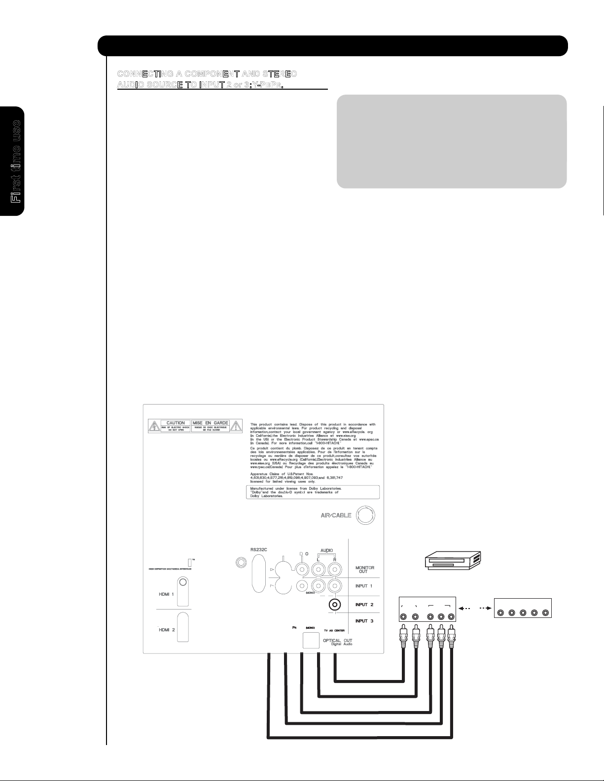
Connecting External Audio/Video Devices
CONNECTING A COMPONENT AND STEREO
AUDIO SOURCE TO INPUT 2 or 3:Y-PBPR.
1. Connect the cable from the Y OUT of the
Laserdisc/DVD player or HDTV set top box to
the INPUT (Y) jack, as shown on the Rear
panel below.
NOTE: 1. Completely insert the connection cord
plugs when connecting to rear panel jacks.
The picture and sound that is played back
will be abnormal if the connection is loose.
2. See page 19 for tips on REAR PANEL
2. Connect the cable from the PB/CBOUT or B-
CONNECTIONS.
Y OUT of the Laserdisc/DVD player or HDTV
set top box to the INPUT (PB)jack.
First time use
3. Connect the cable from the PR/CROUT or RY OUT of the Laserdisc/DVD player or HDTV
set top box to the INPUT (PR) jack.
4. Connect the cable from the AUDIO OUT R of
the Laserdisc/DVD player or HDTV set top box
to the INPUT (AUDIO/R) jack.
5. Connect the cable from the AUDIO OUT L of
the Laserdisc/DVD player or HDTV set top box
to the INPUT (AUDIO/L) jack.
6. Press the INPUTS button, then select INPUT 2
or 3 from the INPUTS menu to view the
program from the Laserdisc/DVD player or
HDTV set top box.
7. Select CABLE or AIR to return to the last
channel tuned.
CABLE
or
Air signal
AUDIO
R
Back of
DVD Player
OUTPUT
PR/CR PB/CB Y
L
DVD Player
VIDEO
OR
OUTPUT
L R Y P B P
HDTV Set-Top Box
R
22
Page 23

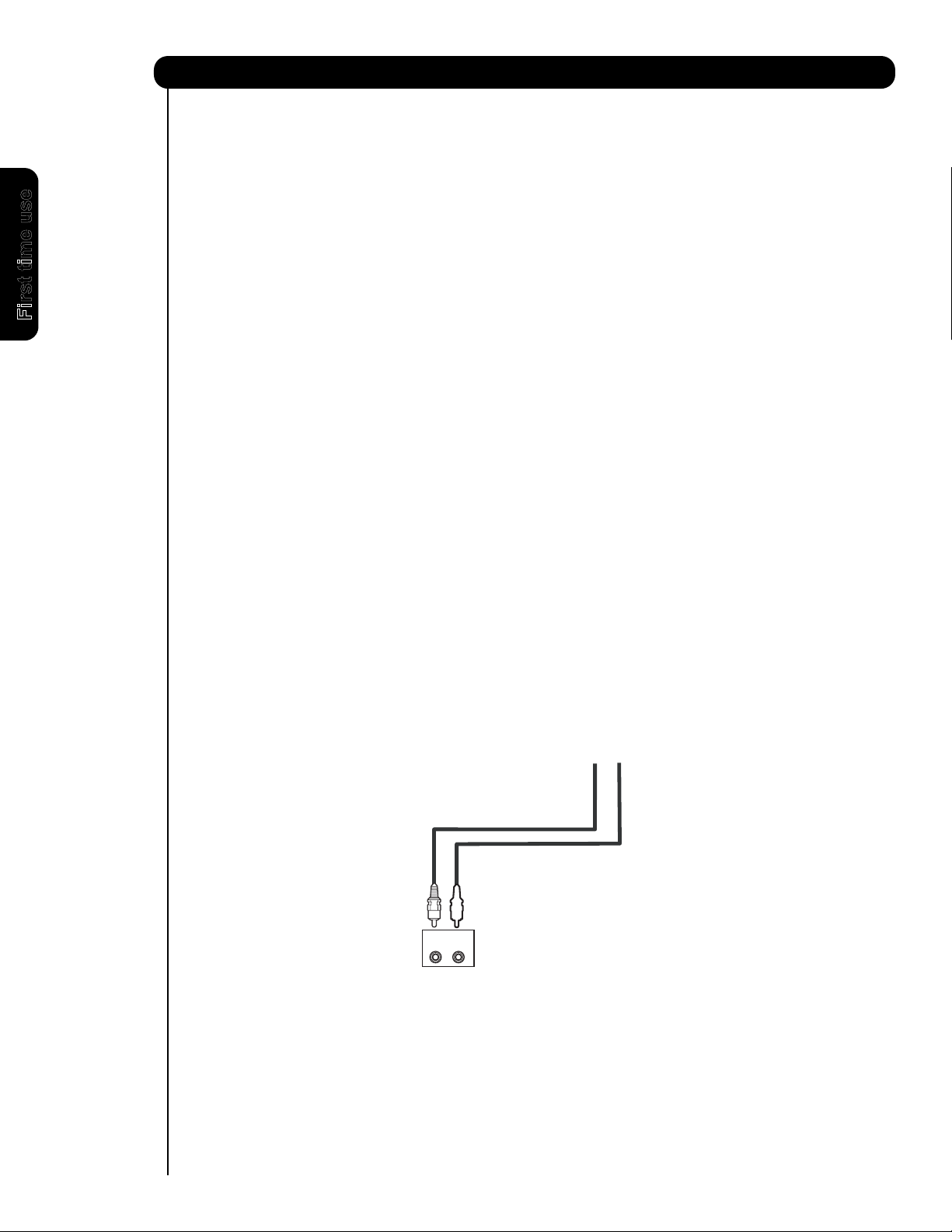
CONNECTING A VIDEO AND MONAURAL AUDIO
SOURCE TO INPUT 1 ~ FRONT INPUT
1. Connect the cable from the VIDEO OUT of the
VCR or the laserdisc player to the INPUT
(VIDEO) jack, as shown on the Rear Panel on the
right.
2. Connect the cable from the AUDIO OUT of the
VCR or the laserdisc player to the INPUT
(MONO)/L(AUDIO) jack.
3. Press the INPUTS button, then select INPUT 1
2,3 or Front from the INPUTS menu to view the
program from the VCR or the laserdisc player.
4. Select CABLE or AIR from the INPUTS menu to
return to the previous channel.
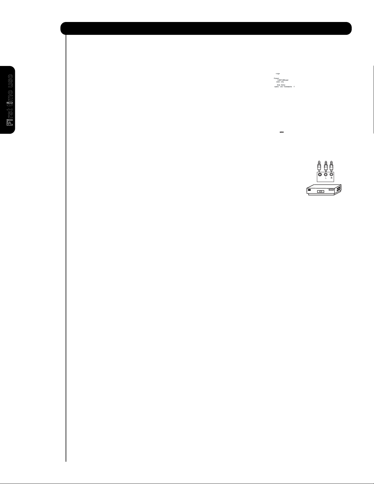
CONNECTING AN EXTERNAL AUDIO AMPLIFIER
To monitor the audio level of the Plasma TV to an
external audio amplifier, connect the system as
shown on the right. The “OPTICAL OUT” from the
Rear Panel is a fixed output. The Volume of the
amplifier is controlled by the amplifier, not by the
Plasma Television. The OPTICAL OUT terminal
outputs all audio sources with Optical IN capability.
1. Connect an optical cable from the Optical out to
the Optical input of a separate Stereo System
Amplifier as shown on the Rear Panel on the
right.
CONNECTING MONITOR OUT
The MONITOR OUT terminal outputs video and
audio of CABLE/AIR and INPUTS 1, 2, 3 and Front.
It does not output component and HDMI video.
1. Connecting S-Video:
Connect the cable from the S-VIDEO OUT of
the Rear Panel to the INPUT (S-VIDEO) jack, of
the VCR or Laserdisk player.
Connecting Video:
Connect the cable from the VIDEO INPUT of
the VCR or the laserdisc player to the VIDEO
out jack on the TV Rear Panel.
2. Connect the cable from the AUDIO IN R of the
VCR or the laserdisc player to the OUTPUT
(AUDIO/R) jack on the TV Rear Panel.
3. Connect the cable from the AUDIO IN L of the
VCR or the laserdisc player to the OUTPUT
(AUDIO/L) jack on the TV Rear Panel.
Optional
CABLE
or
Air signal
VCR or other external
components
R L V
INPUT
S-VIDEO
NOTE: When making video connections, connect S-Video only or Video only. If both are connected, S-Video
takes priority.
23
Page 24
24
First time use
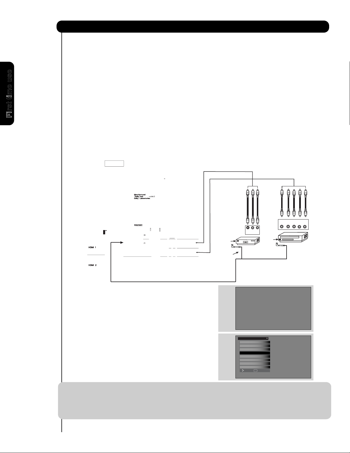
Connecting External Video Sources
Your HITACHI Plasma Television is equipped with an AV Net feature. This feature helps to control your
external Audio/Video equipment (VCR, Set Top Box, DVD, etc.). Once this is setup, it allows your IR Blaster
cable to control your equipment using your HITACHI Plasma TV Remote Control. You can use your
HITACHI remote control to control the Audio/Video equipment command without the equipment’s remote
control.
The Plasma Television Rear Panel has 2 IR Out jacks. Each IR Blaster cable can connect up to 2
external Audio/Video components. Therefore, you can connect the Plasma Television with up to four
components. Please see the following example of an AV Net setup between your Hitachi Plasma
Television and external Audio/Video equipment (VCR and DVD Player).
CONNECTING EXTERNAL AUDIO/VIDEO COMPONENTS TO IR OUT FOR AV NET
1. Connect your external Audio/Video components to the Rear Panel shown below.
2. Connect the IR Blaster cable to the IR OUT terminal of the Rear Panel.
3. Place the IR Blaster in front of the infrared sensor of the external components you wish to control.
NOTE:
1. The Rear Panel has two IR OUT terminals which can control up to a total of four external components.
2. The IR Blaster must be placed in front of the external components infrared sensor for the AV Net
to work. Double-sided mounting tape may be used to hold the IR Blaster in place.
3. The correct codes must be chosen for each of the Audio/Video components for the AV Net to
function properly.
Set The Inputs
S
et The Screen Saver
Set The AV NET
Set the Menu Options
Set The IR Out
Set The Closed Captions
Select The Quick Start Option
Setup
Reset the Software
Move
SEL
Return
4. ACCESS THE AV NET SETUP WIZARD
Press the MENU button.
5. Use the CURSOR PAD 왔 or channel scroll down
to highlight SETUP.
6. Press the SELECT or CURSOR PAD 왘 button to
select.
7. Use the CURSOR PAD 왔 or channel scroll to
highlight the SET AV NET features then press the
SELECT button.
8. Follow the Setup procedure on pages 69-76.
DVD
V L R
OUTPUT
VCR
Infrared
Sensor
Infrared
Sensor
IR
Blaster
OUTPUT
Y PB/CBPR/C
R
R L
Page 25
Connecting External Video Sources
Your HITACHI Plasma Television is equipped with a G-LINKTM feature. This connection is necessary for the
TV Guide On Screen
TM
system to enable VCR recording features. Once you setup the G-LINK
TM
(IR Blaster)
connector, then you can use your HITACHI Plasma TV Remote Control and TV Guide On Screen
system to control your VCR recording features.
The Plasma Television Rear Panel has IR OUT/G-LINK
2 external Audio/Video components. Please see the following example of a G-LINK
TM
terminals. One IR Blaster cable can connect up to
TM
setup between your
HITACHI Plasma Television and external Audio/Video equipment (VCR).
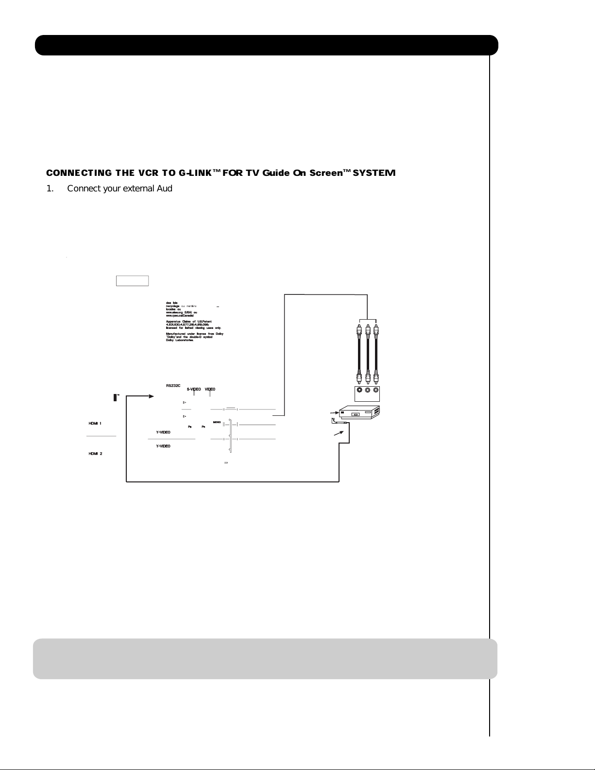
CONNECTING THE VCR TO G-LINK
TM
FOR TV Guide On Screen
TM
SYSTEM
1. Connect your external Audio/Video components to the Rear Panel shown below.
TM
. Connect the IR Blaster cable to the IR OUT/G-LINK
2
output terminal of the Rear Panel.
3. Place the IR Blaster in front of the infrared sensor of the external components you want to control.
TM
V L R
OUTPUT
Infrared
Sensor
IR
Blaster
VCR
NOTE: 1. The IR Blaster must be placed in front of the external components infrared sensor for the G-LINKTM feature to
work.
G-LINKTM connections are available on both IR OUT terminals.
2.
25
Page 26
26
Page 27
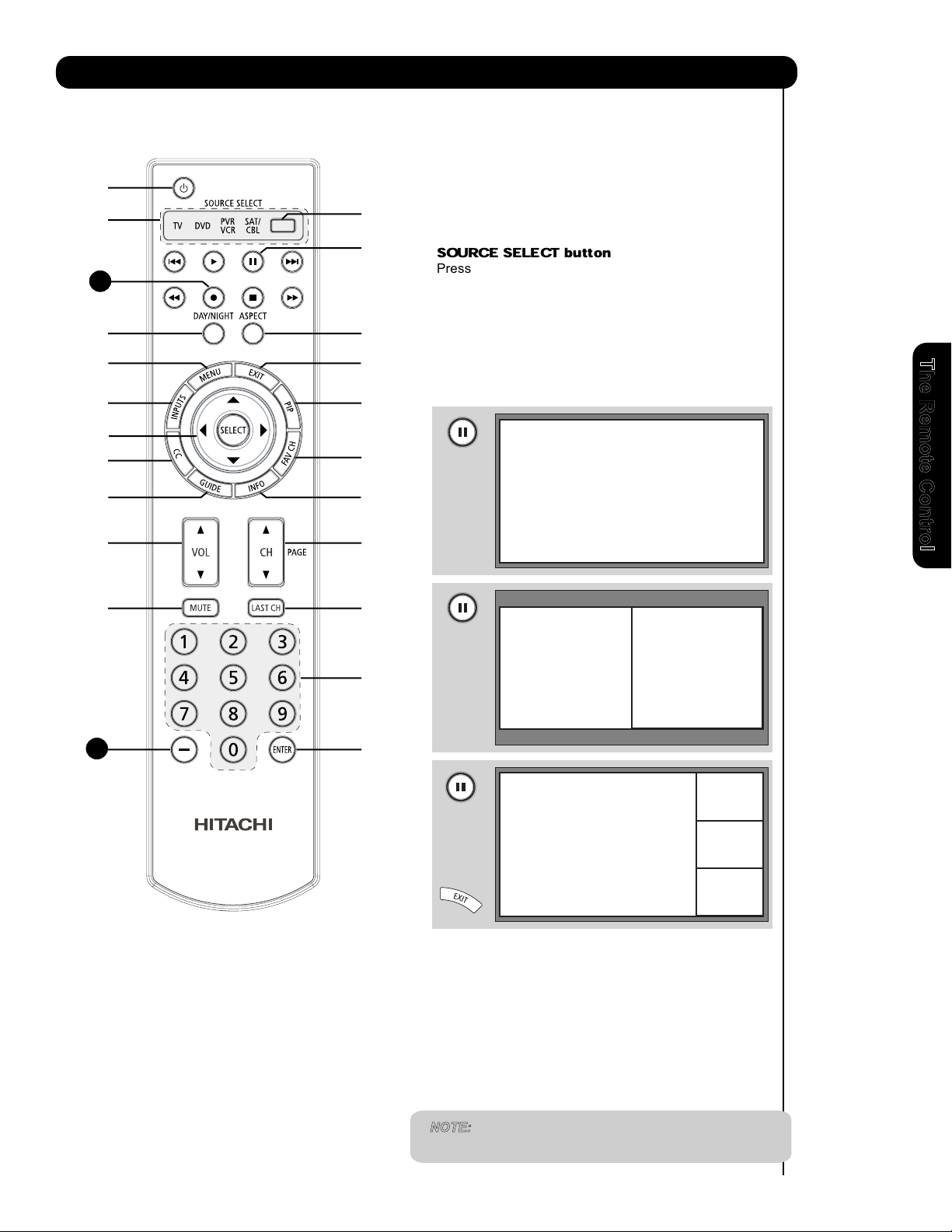
How to Use the Remote to Control Your TV
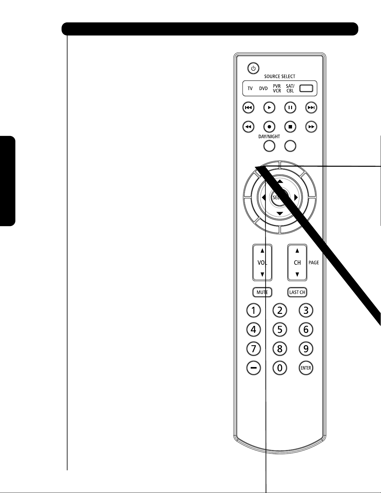
쐃
POWER button
Press this button to turn the TV set on or off when
the remote is in TV mode. (See page 26 for instructions
on how to set the remote control to TV mode).
쐃
쐇
19
쐄
쐆
쐎
쐈
쐉
씈
씊
씊
쐋
쐏
쐂
쐊
쐅
씋
씉
씋
씌
MODE Indicator
쐇
Turns on or blinks three times to show remote control
mode.
쐋
SOURCE SELECT button
Press this button to select remote control mode.
PAUSE
쐏
Press the PAUSE button to freeze the picture.
Press the EXIT button to return the picture to
motion. Press the PAUSE button repeatedly to
cycle through the three different freeze modes (see
page 35).
button
Freeze
The Remote Control
씋
1
8
씋
DA
Y/NIGHT button
쐄
Press this button to toggle between Day (Normal),
Day (Dynamic) and Night picture mode settings. Select
DAY for day time viewing with more brightness and
contrast to compete with room light. Select NIGHT
for night time viewing with less brightness and
contrast for a more detailed picture (see page 46
for settings changes).
Freeze
Freeze
Freeze
Freeze
NOTE: For automatic DAY/NIGHT picture mode settings,
see page 66.
27
Page 28
How to Use the Remote to Control Your TV
IMAGE INPUT
IMAGE INPUT
IMAGE INPUT
IMAGE INPUT
18
The Remote Control
28
Page 29
How to Use the Remote to Control Your TV
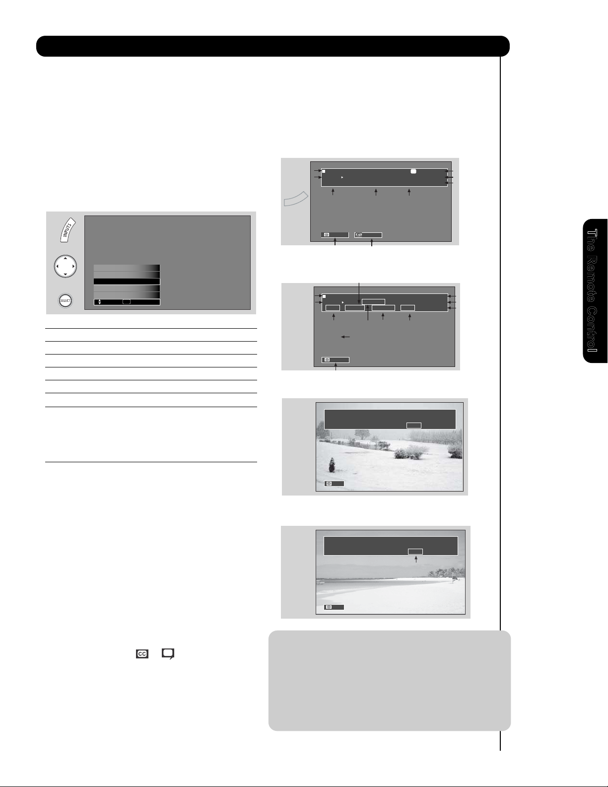
NOTE: 1. Press the INFO button again or the EXIT
button to return to normal viewing.
2. The Aspect setting will not be shown if
the channel is locked.
S-IN: 1
480i 3:17PM
Auto
DIGITAL CHANNELS
Digital Closed Caption
This icon will appear only when
receiving a Digital Broadcast with
Closed Captioning.
Show Name Air 8
3:00PM-
3:30PM KXYZ-HD
ST TV-G 480i 3:17PM
Auto STEREO
Program Run Time
Program Information
Broadcast
Rating
Picture Format
Audio
Broadcast
Main Picture Source
and channel indication
Broadcast channel
identication
Clock
Closed
Caption setting
Audio Source
Selection
ANALOG CHANNELS
Show Name Air 15-1
3:00PM-
3:30M KPBS-HD
ST 1080i 3:17PM
Auto
Program Run Time
Program Information
Broadcast
Rating
Picture Format
Audio
Broadcast
Main Picture Source
and channel indication
Broadcast channel
identication
Clock
Closed
Caption setting
DTvCC TV-G
REGION 5
Alternate
Rating
Program Description
(Press INFO again for a more detailed description)
When a Component Video: Y-PbPr
Input
is connected to INPUT 3
Input Signal
Format
Y-PBPR: 3
480i 3:17PM
Auto
When an S-VIDEO Input is connected
to
INPUT 1
MENU button
The MENU button will start the On-Screen Display.
EXIT button
This button will exit all On-Screen Displays.
쐆
쐎
쐊
INPUTS button
When the remote control is in TV mode, press this
button to access the INPUTS menu. Use the
CURSOR and SELECT buttons to scroll and select
the inputs that are being used. Pressing the
INPUTS button repeatedly will also cycle through
the Inputs menu items. Then press the SELECT
button to select.
INPUT 1 Select to choose INPUT 1.
INPUT 2 Select to choose INPUT 2.
INPUT 3 Select to choose INPUT 3.
INPUT- FRONT Select to choose FRONT INPUT .
HDMI 1 Select to choose HDMI 1 INPUT.
HDMI 2 Select to choose HDMI 2 INPUT.
HDMI-Front
Photo Input
Input 2
Air / Cable
Move SEL Select
Input 1
HDMI- FRONT Select to choose FRONT HDMI INPUT.
AIR/CABLE Select between Air or Cable signal.
CURSOR buttons/SELECT button
All the On-Screen Display features can be set or
adjusted by using the CURSOR buttons and the
SELECT button, except for numeric entries. Press
the CURSOR buttons toward desired direction and
press the SELECT button to select.
쐅
쐈
쐉
PICTURE-IN-PICTURE button
See separate section on pages 33-34 for a more
detail description.
CLOSED CAPTIONS (CC) button
Use this button to display the dialogue, narration,
and/or sound effects of a television program or home
GUIDE button
Press this button to access the TV Guide On Screen
TM
interactive display (see page 54-56). Press this
button to access the Channel Guide of the (CBL),
and (SAT/STB) while in (CBL)(SAT/STB) mode.
video which are displayed on the TV screen when
available. Your local TV program guide denotes
these programs as or .
씈
PHOTO INPUT Select to access your pictures from a
digital camera, MMC/SD Flash memory
or memory card connected to the Photo
Input in the front panel of the Plasma
TV (see pages 30-31).
INFO button
Press this button when you want to check the
channel being received, the picture source, if
the channel has stereo (ST) or second audio
program (SAP), the time, CHANNEL ID and if
the TIMER is set.
씉
The Remote Control
29
Page 30
How to Use the Remote to Control Your TV
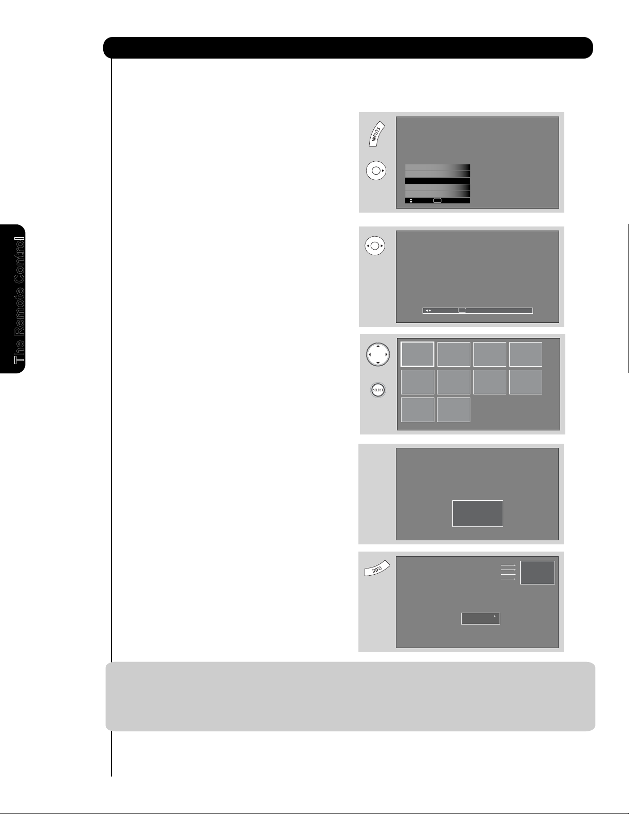
HDMI 1
HDMI-Front
Photo Input
Input 1
Move S
EL Sel.
Air / Cable
No. 02/08
06/13/05
2048x1536
DSC00467
Rotate
Slideshow
Picture No.
Date
Resolution
File Name
PHOTO INPUT
This feature is useful for viewing digital still pictures from your digital camera, MMC/SD memory cards using the
Photo Input in the front panel of the TV.
1. Press the INPUTS button to cycle through the
INPUTS selections until the PHOTO INPUT is
selected. Press the SELECT button or
CURSOR PAD 왘.
2. Press the CURSOR PAD 왗 or 왘 to access the
next or previous photo.
SEL Thumbnail [0-9] Jump
Next
The Remote Control
3. Press the SELECT button to view THUMBNAIL.
4. Use the CURSOR PAD buttons 왖, 왔, 왗 or 왘
and the SELECT button to navigate and select
individual chosen photos.
5. Press the picture number to jump from picture
to picture.
Please Enter
Picture Number
--
6. Press the INFO button to access PHOTO Input
menu and to view Photo information.
7. Press the CURSOR PAD 왖 or 왔 and the
SELECT button to navigate and select the
PHOTO Input menu.
NOTES: 1. Contrast will decrease automatically if stationary images such as digital still photos are left
on the screen for more than 3 minutes.
2. The maximum number of digital Photos that can be displayed is 999.
3. Press INFO button to show Picture Numbers in Thumbnail view, plus other information in
individual photos.
4. The screen may show “Input device not detected” if the MMC/SD memory card is not inserted.
30
Page 31

How to Use the Remote to Control Your TV
ROTATE
Select this menu item to rotate selected photos
either clockwise (CURSOR PAD 왘) and
counterclockwise (CURSOR PAD 왗).
SLIDESHOW
Select this menu item to start a slideshow of the
digital photos. While the Interval sub menu is
highlighted, press the SELECT button to cycle
through the interval time from 5, 10 and 30 seconds.
Press the SELECT button to stop on a chosen
picture of the slideshow. After 30 seconds, the
slideshow will resume or press the SELECT button
again to continue with the slideshow.
Rotate
Slideshow Start
Rotate
The Remote Control
Interval 5sec
NOTES: 1. Automatic contrast reduction also applies during SLIDESHOW, then press any button to
continue.
2. Photo file names modified on a computer should be 8 characters (Ex. ABCD1234.jpg). 1st
character: letters; 2nd to 4th: letters or numbers; 5th to 8th: numbers. Photo files should be
first placed on a sub directory name with 8 characters (Ex. 123ABCDE). 1st to 3rd: number;
4th to 8th: letters. The sub directory then should be placed on a main directory with a
“dcim” file name format.
3. Supported image types are up to 3072 x 2304; JPEG format should conform with DCF
Standard (Design rule for Camera File System).
4. This TV set displays only digital pictures from digital cameras which meet DCF Standard.
Pictures that were copied, edited or modified on a computer may not be displayed on the TV
set.
31
Page 32

How to Use the Remote to Control Your TV
VOLUME (VOL), MUTE button
Press the VOLUME button (왖 or 왔) until you obtain
the desired sound level.
To reduce the sound to one half of normal volume
(SOFT MUTE) to answer the telephone, etc., press
the MUTE button. Press the MUTE button again to
turn the sound off completely (MUTE). To restore
the sound, press the MUTE button one more time,
or VOL UP (
왖).
C
losed Captioning will display automatically when
MUTE/SOFT MUTE is on and Closed Caption is set
to AUTO (see page 77).
When the TV power is turned off at a volume level
31 or greater, the volume level will default to 30
when the TV is turned on. However, if it is set to a
level 30 or less, the volume level will be at the level
it was set when the TV is turned on.
CHANNEL SELECTOR/FAVORITE CHANNEL
(FAV CH)/ENTER buttons
The C
HANNEL SELECTOR buttons are used to
select channels, lock access code, etc. Use the
CHANNEL SELECTOR buttons to enter one, two,
or three numbers to select channels. Enter 0 first
for channels 1 to 9, or simply press the single digit
channel you wish to tune then press the ENTER button
for the TV to tune. Channel selection may also be
performed by CHANNEL (CH) UP (
왖) or
CHANNEL
(CH) DOWN (
왔).
P
ress the FAV CH button to switch to Favorite
(FAV) channel mode. You will know you are in
Favorite Channel mode when (FAV) is displayed
and the displayed channel is GREEN. Press it
again to return to your regular tuned channels. You
can add any channel to your Favorite channel list
by pressing and holding down the FAV CH button
until the displayed channel turns from WHITE to
highlighted GREEN. You can also delete a channel
from your favorite channel list by pressing and
holding down the FAV CH button until the
displayed channel turns highlighted GREEN to
WHITE.
(-) DASH button
LAST CHANNEL button
Press this button to toggle between the current and
last channel viewed.
RECORD button
Press to record programs when the remote is in
PVR/VCR mode.
씋
Cable 6
FAV Cable 6
Cable 6
Volume 8
Soft Mute 8
Mute 8
1
8
19
씊
Use the (-) DASH button with the CHANNEL
SELECTOR buttons to enter Digital Channels that
have subchannel numbers indicated by (-) DASH
(example 15-1).
1
7
The Remote Control
32
Page 33

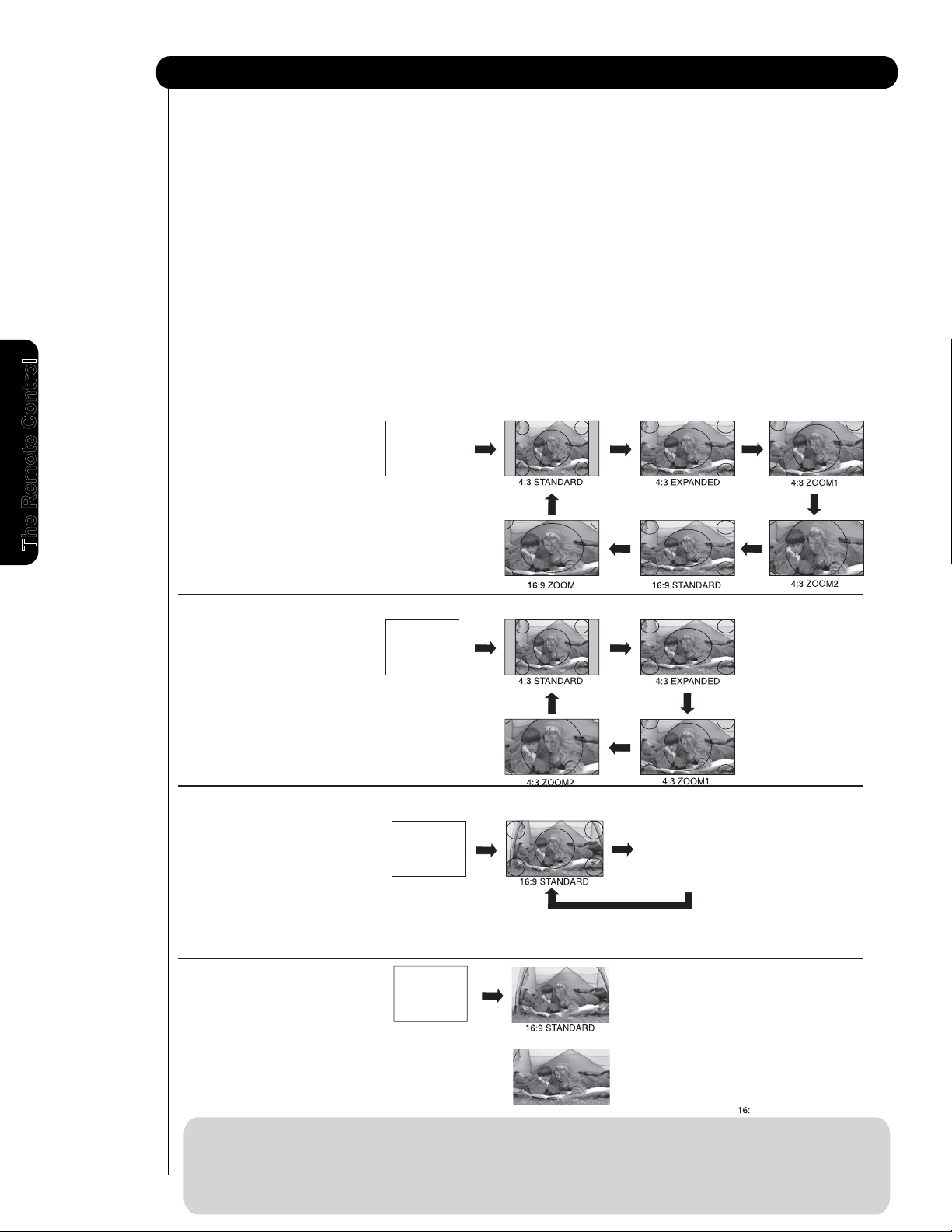
SPLIT MODE PICTURE-IN-PICTURE
Split Mode PIP displays the main picture and sub-
picture evenly on the screen.
SWAP
Main Picture
Sub Picture
Main Picture
Sub Picture
SWAP
POP MODE PICTURE-IN-PICTURE
POP Mode PIP displays the sub-picture outside of
the main picture. Use the CURSOR PAD (왖 or 왔)
to move the sub-picture. This feature is not
available with a 1080p/1080i/720p signal. Please
refer to the PICTURE-IN-PICTURE modes table in
next page.
Picture-In-Pictur
e (PIP)
햲
To select between main picture and PIP sub picture,
use the CURSOR PAD button the remote. The Orange
highlighted channel display will move with every press
of the CURSOR PAD buttons.
The Picture-in-Picture feature is convenient when you
want to watch more than one program at the same
time.You can watch a TV program while viewing other
programs from any of the video inputs.
Use connection at right to view VCR program as a
sub picture while viewing another program as main
picture (CABLE/AIR Digital channel).
Back of
VCR
OUTPUT
VCR
Video
Your HITACHI Plasma TV incorporates one Tuner
technology designed for improved viewing enjoyment
This feature allows you to view Digital Channels and
Video inputs on both the main picture and sub picture
simultaneously, with separate control.
Analog channels cannot be viewed in PIP mode.
Please see table in next page for PIP availability.
햲 PIP button
Press the PIP button and a sub-picture will appear
in one of three different modes (POP, PIP, or
SPLIT), depending on the INPUT signal. To change
the PIP mode, use the PIP button to cycle through
the three different modes.
The Remote Control
NOTE : 1. Press the CURSOR PAD (왗 or 왘) to
enable the sub-picture sound.
33
Page 34

Picture-In-Picture (PIP)
Main Picture
Sub Picture
SWAP
PIP Sub Digital (Air or Cable) Component/Composite/S-IN/HDMI
Mode 1080i 720p 480p 480p 480i 480i 1080i/p 720p 480p 480p 480i 480i
Main 16x9 16x9 16x9 4x3 16x9 4x3 16x9 16x9 16x9 4x3 16x9 4x3
1080i 16x9
䋭䋭䋭䋭䋭䋭䋭䋭䋭䋭䋭䋭
720p 16x9
䋭䋭䋭䋭䋭䋭䋭䋭䋭䋭䋭䋭
480p 16x9
䋭䋭䋭䋭䋭䋭䋭䋭䋭䋭䋭䋭
480p 4x3 䋭䋭䋭䋭䋭䋭Yes Yes Yes Yes Yes Yes
480i 16x9
䋭䋭䋭䋭䋭䋭䋭䋭䋭䋭䋭䋭
Digital
(Air or
Cable)
480i 4x3
䋭䋭䋭䋭䋭䋭
Yes Yes Yes Yes Yes Yes
1080i/p 16x9 䋭䋭䋭䋭䋭䋭䋭䋭䋭䋭䋭䋭
720p 16x9
䋭䋭䋭䋭䋭䋭䋭䋭䋭䋭䋭䋭
480p 16x9 Yes*1 Yes*1 Yes*1 Yes*1 Yes*1 Yes*1
䋭䋭䋭䋭䋭䋭
480p 4x3 Yes Yes Yes Yes Yes Yes
䋭䋭䋭䋭䋭䋭
480i 16x9 Yes*1 Yes*1 Yes*1 Yes*1 Yes*1 Yes*1 䋭䋭䋭䋭䋭䋭
POP
Component
Composite
S-IN
HDMI
480i 4x3 Yes Yes Yes Yes Yes Yes
䋭䋭䋭䋭䋭䋭
1080i 16x9
䋭䋭䋭䋭䋭䋭
Yes Yes Yes*2
䋭
Yes*2
䋭
720p 16x9 䋭䋭䋭䋭䋭䋭Yes Yes Yes*2 䋭Yes*2 䋭
480p 16x9
䋭䋭䋭䋭䋭䋭
Yes Yes Yes*2
䋭
Yes*2
䋭
480p 4x3
䋭䋭䋭䋭䋭䋭䋭䋭䋭䋭䋭䋭
480i 16x9 䋭䋭䋭䋭䋭䋭Yes Yes Yes*2 䋭Yes*2 䋭
Digital
(Air or
Cable)
480i 4x3
䋭䋭䋭䋭䋭䋭䋭䋭䋭䋭䋭䋭
1080i/p 16x9 Yes Yes Yes
䋭
Yes
䋭䋭䋭䋭䋭䋭䋭
720p 16x9 Yes Yes Yes
䋭
Yes
䋭䋭䋭䋭䋭䋭䋭
480p 16x9 Yes*2 Yes*2 Yes*2 䋭Yes*2 䋭䋭䋭䋭䋭䋭䋭
480p 4x3
䋭䋭䋭䋭䋭䋭䋭䋭䋭䋭䋭䋭
480i 16x9 Yes*2 Yes*2 Yes*2
䋭
Yes*2
䋭䋭䋭䋭䋭䋭䋭
PIP
16x9
Component
Composite
S-IN
HDMI
480i 4x3
䋭䋭䋭䋭䋭䋭䋭䋭䋭䋭䋭䋭
1080i 16x9
䋭䋭䋭䋭䋭䋭䋭䋭
Yes*1 Yes Yes*1 Yes
720p 16x9
䋭䋭䋭䋭䋭䋭䋭䋭
Yes*1 Yes Yes*1 Yes
480p 16x9 䋭䋭䋭䋭䋭䋭䋭䋭Yes*1 Yes Yes*1 Yes
480p 4x3
䋭䋭䋭䋭䋭䋭䋭䋭䋭䋭䋭䋭
480i 16x9
䋭䋭䋭䋭䋭䋭䋭䋭
Yes*1 Yes Yes*1 Yes
Digital
(Air or
Cable)
480i 4x3
䋭䋭䋭䋭䋭䋭䋭䋭䋭䋭䋭䋭
1080i/p 16x9 䋭䋭䋭Yes 䋭Yes 䋭䋭䋭䋭䋭䋭
720p 16x9
䋭䋭䋭
Yes
䋭
Yes
䋭䋭䋭䋭䋭䋭
480p 16x9
䋭䋭䋭
Yes*2
䋭
Yes*2
䋭䋭䋭䋭䋭䋭
480p 4x3 䋭䋭䋭䋭䋭䋭䋭䋭䋭䋭䋭䋭
480i 16x9
䋭䋭䋭
Yes*2
䋭
Yes*2
䋭䋭䋭䋭䋭䋭
PIP
4x3
Component
Composite
S-IN
HDMI
480i 4x3
䋭䋭䋭䋭䋭䋭䋭䋭䋭䋭䋭䋭
1080i 16x9 䋭䋭䋭䋭䋭䋭Yes Yes Yes Yes Yes Yes
720p 16x9
䋭䋭䋭䋭䋭䋭
Yes Yes Yes Yes Yes Yes
480p 16x9
䋭䋭䋭䋭䋭䋭
Yes Yes Yes Yes Yes Yes
480p 4x3
䋭䋭䋭䋭䋭䋭
Yes Yes Yes Yes Yes Yes
480i 16x9 䋭䋭䋭䋭䋭䋭Yes Yes Yes Yes Yes Yes
Digital
(Air or
Cable)
480i 4x3
䋭䋭䋭䋭䋭䋭
Yes Yes Yes Yes Yes Yes
1080i/p 16x9 Yes Yes Yes Yes Yes Yes
䋭䋭䋭䋭䋭䋭
720p 16x9 Yes Yes Yes Yes Yes Yes 䋭䋭䋭䋭䋭䋭
480p 16x9 Yes Yes Yes Yes Yes Yes
䋭䋭䋭䋭䋭䋭
480p 4x3 Yes Yes Yes Yes Yes Yes
䋭䋭䋭䋭䋭䋭
480i 16x9 Yes Yes Yes Yes Yes Yes
䋭䋭䋭䋭䋭䋭
SPLIT
Component
Composite
S-IN
HDMI
480i 4x3 Yes Yes Yes Yes Yes Yes
䋭䋭䋭䋭䋭䋭
Yes*1: Auto Aspect OFF
Yes*2: Auto Aspect ON
PIP Specifications Table
PIP MODE PICTURE-IN-PICTURE
Select CABLE/AIR or INPUT 1~3, Front from the INPUTS menu. Select a channel that has a 1080p/1080i/720p signal.
To prevent a pattern burn, occasionally move the sub-picture using the CURSOR PAD.
The Remote Control
34
Page 35

Picture-In-Picture (PIP)
Hot Springs Clay Mask
C/O John Doe
Run-Spa Retreat
P.O. Box 55512
Any Town, USA 98765
Check or
Money Order Only
1-800-555-1212
SPLIT FREEZE
Press the PAUSE button to freeze the picture you
are currently viewing (only the right sub-picture will
freeze). Press the EXIT button to return to normal
viewing.
Main Picture
Sub Picture
STROBE FREEZE
Press the PAUSE button to freeze three frames of
the picture you are currently viewing (only the 3
sub-pictures will freeze). Press the EXIT button to
return to normal viewing. This feature is useful for
viewing a moving picture that has many details, for
example, a close play in a sporting event or a golf
swing.
MAIN FREEZE
Press the PAUSE button to freeze one frame of the
picture you are currently viewing and the frozen
frame will show in the Main Picture. Press the EXIT
button to return to normal viewing. This feature is
useful for freezing a picture frame with addresses.
35
Page 36

The Remote Control for Cable Box Functions
OPERATING THE PRECODED
FUNCTION FOR YOUR CABLE BOX.
This remote is designed to operate different types of
cable boxes. You must first program the remote to
match the remote system of your cable box (refer to
pages 42-43 for pre-codes).
햲
1. Turn ON your cable box.
햲
햳
2. To switch to Cable (CBL) pre-coded mode, use the
SOURCE SELECT button on the remote control
to position the LED light to the corresponding
selection SAT/CBL.
햳
햳
3. Hold down the SOURCE SELECT button on the
remote and enter the four digit preset code that
matches your cable box as shown on pages 42-43.
Release the SOURCE SELECT button. The indicator
light will flash 3 times if the code was accepted.
햳
4. Aim the remote at the cable box and press the
POWER button. The remote will turn off your cable
The Remote Control
box when the correct four digit preset code is
entered. When this occurs, the remote control is
programmed for your cable box. If the cable box
does not turn off, try a different four digit preset
code.
햲
햲
햲
5. The remote will now control your Cable box.
NOTE: 1. If your cable box cannot be operated after
performing the above procedures, your
cable box code has not been precoded
into the remote.
2. In the unlikely event that your cable box
cannot be operated after performing the
above procedures, please consult your
cable box operating guide.
3. The remote control will remember the
codes you have programmed until the
batteries are removed from the
remote control. After replacing the
batteries repeat the entire programming
procedure as stated above.
햲 PRECODED CABLE BOX buttons
These buttons transmit the chosen precoded cable
codes :
36
햳 EXCLUSIVE TV buttons
These buttons are for operating the TV :
MY CABLE BOX CODE IS:
NOTE: Refer to instruction manual of the Cable Box
for operation of the buttons exclusively for
the Cable Box.
Page 37

The Remote Control for Set-Top-Box/Satellite Receiver
OPERATING THE PRECODED FUNCTION FOR
YOUR SET-TOP-BOX/SATELLITE RECEIVER.
This remote is designed to operate different types of
set-top-box/satellite systems. You must first program
the remote to match the remote system of your set-
top-box/satellite systems (refer to pages 42-43 for pre-
codes).
1. Turn ON your set-top-box/satellite systems.
햲
햳
Functions
2. To switch to set-top-box/satellite (SAT) pre-coded
mode, use the SOURCE SELECT button on the
remote control to position the LED light to the
corresponding selection SAT/CBL.
3. Hold down the SOURCE SELECT button on the
remote and enter the four digit preset code that matches
your set- top-box/satellite receiver as shown on page
42-43. Release the SOURCE SELECT button. The
indicator light will flash 3 times if the code was accepted.
4. Aim the remote at the set-top-box/satellite receiver
and press the POWER button. The remote will turn
off your set-top-box/satellite receiver when the
correct four digit preset code is entered. When this
occurs, the remote control is programmed for your
set-top-box/satellite receiver. If the set-topbox/satellite receiver does not turn off, try a
different four digit preset code.
5. The remote will now control your set-top-box/
satellite receiver.
NOTE: 1. If your set-top-box/satellite receiver
cannot be operated after performing the
above procedures, your set-top-box/
satellite receiver code has not been
precoded into the remote.
2. In the unlikely event that your set-topbox/satellite receiver cannot be operated
after performing the above procedures,
please consult your set-top-box/satellite
receiver operating guide.
3. The remote control will remember the
codes you have programmed until the
bat teries are removed from the
remote control. After replacing the
batteries repeat the entire programming
procedure as stated above.
The Remote Control
햲
햲 PRECODED SET-TOP-BOX/SATELLITE
RECEIVER buttons
These buttons transmit the chosen pre-coded
set-top-box/satellite codes :
햳 EXCLUSIVE TV buttons
These buttons are for operating the TV :
MY Satellite RECEIVER/
SET-TOP-BOX CODE IS:
NOTE: Refer to instruction manual of the Set-Top-
Box/Satellite Receiver for operation of the
buttons exclusively for the Set-TopBox/Satellite Receiver.
37
Page 38

The Remote Control for DVD Functions
OPERATING THE PRECODED
FUNCTION FOR YOUR DVD PLAYER.
This remote is designed to operate different types of
DVD players. You must first program the remote to
match the remote system of your DVD player (refer to
pages 42-43 for pre-codes).
햲
햲
햳
1. Turn ON your DVD player.
2. To switch to DVD pre-coded mode, use the
SOURCE SELECT button on the remote control to
position the LED light to the corresponding selection
DVD.
3. Hold down the SOURCE SELECT button on the
remote and enter the four digit preset code that
matches your DVD player, as shown on pages 42-43.
Release the SOURCE SELECT button. The indicator
light will flash 3 times if the code was accepted.
4. Aim the remote at the DVD player and press the
POWER button. The remote will turn off your DVD
The Remote Control
player when the correct four digit preset code is
entered. When this occurs, the remote control is
programmed for your DVD player. If the DVD
player does not turn off, try a different four digit
preset code.
햲
햳
햲
햳
햳
햳
햳
햲
햲
5. The remote will now control your DVD player.
NOTE: 1. If your DVD player cannot be operated
after performing the above procedures,
your DVD player code has not been
precoded into the remote.
2. In the unlikely event that your DVD player
cannot be operated after performing the
above procedures, please consult your
DVD player operating guide.
3. The remote control will remember the
codes you have programmed until the
batteries are removed from the
remote control. After replacing the
batteries repeat the entire programming
procedure as stated above.
햲 PRECODED DVD Buttons
These buttons transmit the chosen precoded
DVD codes :
-Power
-Menu
-Info
-Cursor & Select
햳 EXCLUSIVE TV Buttons
These buttons are for operating the TV :
-Day/Night
-Aspect
-PIP
-Exit
MY DVD PLAYER CODE IS:
-Number PAD
-Play, Stop, Pause,
RWD, FWD, Skip RWD,
kip FWD.
S
-CC
-Vol Up & Down
-Mute
-Inputs (Only if
programmed, refer
t
o page 40)
38
NOTE: Refer to instruction manual of the DVD Player
for operation of the buttons exclusively for
the DVD Player.
Page 39

The Remote for VCR/PVR Functions
OPERATING THE PRECODED FUNCTION FOR
YOUR VCR/PVR (Personal Video Recorder).
This remote is designed to operate different types of
VCRs/PVRs. You must first program the remote to
match the remote system of your VCR/PVR (refer to
pages 42-43 for pre-codes).
1. Turn ON your VCR/PVR.
2. To switch to VCR/PVR pre-coded mode, use the
SOURCE SELECT button on the remote control to
position the LED light to the corresponding
selection PVR/VCR.
3. Hold down the SOURCE SELECT button on the
remote and enter the four digit preset code that
matches your VCR/PVR, as shown on pages 42-43.
Release the SOURCE SELECT button. The indicator
light will flash 3 times if the code was accepted.
4. Aim the remote at the VCR/PVR and press the
POWER button. The remote will turn off your PVR
when the correct four digit preset code is entered.
When this occurs, the remote control is
programmed for your VCR/PVR. If the VCR/PVR
does not turn off, try a different four digit preset
code.
5. The remote will now control your VCR/PVR.
햲
햳
햲
햳
햲
햳
햲
햳
햲
햲
햳
The Remote Control
햲
햲
햲
NOTE: 1. If your VCR/PVR cannot be operated after
performing the above procedures, your
VCR/PVR code has not been precoded
into the remote.
2. In the unlikely event that your VCR/PVR
cannot be operated after performing the
above procedures, please consult your
VCR/PVR operating guide.
3. The remote control will remember the
codes you have programmed until the
batteries ar e removed from the
remote control. After replacing the
batteries repeat the entire programming
procedure as stated above.
햲 PRECODED VCR/PVR Buttons
These buttons transmit the chosen precoded
VCR/PVR codes :
-Power
-Menu
-Exit
-Info
-Record -RWD
햳 EXCLUSIVE TV Buttons
These buttons are for operating the TV :
-Day/Night
-Aspect
-PIP
MY VCR/PVR CODE IS:
-Cursor & Select
-Channel Up & Down
-Number PAD
-Last CH
-CC
-Vol Up & Down
-Mute
-Enter
-Dash (-)
-Play,Pause,Stop
-FWD,Skip FWD
-Inputs (only if
programmed,
efer to page 40)
r
NOTE: Refer to instruction manual of the VCR/PVR
for operation of the buttons exclusively for
the VCR/PVR.
39
Page 40

How to Use the SOURCE
INPUT ACCESS
This optional feature allows the user of the remote
control to setup it’s SOURCE SELECT button to access
the specified input of the TV. Setup for this feature is
applicable to the remote control’s normal mode only and
only applies to the DVD, PVR/VCR and SAT/CBL
modes.
1. Select the desired device mode (DVD, PVR/VCR,
SAT/CBL) by using your SOURCE SELECT button
to position the LED indicator to the corresponding
selection.
2. Hold down the SOURCE SELECT button on the
remote and enter the four digit preset code that
matches your device as shown on pages 42-43.
3. Then enter the assigned input number (1-7) that the
device is related to (refer below to Table 1).
4. Release the SOURCE SELECT button.
SELECT Button
, ,
, ,
5. If done correctly, the device LED indicator will blink
3 times to confirm proper setup.
The Remote Control
6. The remote will now control the desired device.
7. Pressing the INPUTS button will now access the
video input of the desired device.
SETUP EXAMPLE (Hitachi DVD with precode
0573 connected to INPUT 1 of the TV)
Select DVD mode by using your SOURCE SELECT
button to position the LED indicator to DVD.
Hold down the SOURCE SELECT button and
press the numbers 0, 5, 7 and 3.
Then press the number 1 for the assigned input
number of the DVD player.
Table 1
INPUT
INPUT 1 1
INPUT 2 2
INPUT 3 3
INPUT- FRONT 4
HDMI 1 5
HDMI 2 6
HDMI- FRONT 7
ASSIGNMENT NUMBER
Release SOURCE SELECT button.
NOTE: 1. This feature is optional
If done correctly, the device LED indicator will blink
3 times to confirm proper setup.
2. Assigned input numbers can be used more
than once if applicable.
The remote will now control the DVD player.
Press the INPUTS button to instantly access the
video input of your DVD on Input 1.
40
Page 41

The Simple Remote Control
MUTE
FAV CH
SELECT
VOL +
CH -
CH +
GUIDE
VOL -
MENU
INPUTS
POWER
EXIT
햴
햳
햲
햹
햸
햺
햻
햵
햶
햷
POWER button
Pr
ess Power button to turn the Plasma Television ON or OFF.
햳 CH+ (왖) and CH- (왔)
Press the CH+ (왖) up or CH- (왔) down buttons to select desired channel or to navigate the on screen display
features when in GUIDE mode.
햴 VOL- (왗 ) and VOL+ (왘)
Press the VOL- (왗) down or VOL+ (왘) up buttons to select desired sound level or to navigate the on screen
display features when in GUIDE mode.
햵 SELECT button
Press SELECT button to Select when in MENU and GUIDE mode.
햶 MUTE button
T
o reduce the sound to one half of normal volume (SOFT MUTE) to answer the telephone, etc., press the
MUTE button. Press the MUTE button again to turn the sound off completely (MUTE). To restore the sound,
press the MUTE button one more time, or press the VOLUME Up (왘) button.
햷 FAV CH button
Pr
ess FAV CH button to access your favorite channels.
햸 INPUTS button
Pressing the INPUTS button repeatedly will cycle through the input items (see page 29).
햹 EXIT button
When in MENU mode, this button will exit all On-Screen Displays.
햺 MENU button
Press the MENU button to start the On-Screen Display.
햻 GUIDE button
Press this button to access the TV Guide On-ScreenTMsystem (See complete explanation and example on
page 54-56).
NOTE: The Simple Remote cannot be programmed to control external components.
HITACHI has provided a second remote control for your convenience. The Simple Remote Control has the basic
features that are most often used.
The Remote Control
41
Page 42

Remote Control Codes
A
BC ........................ 0003,0008, 0011 GOI.................................0775,1775 1278 Panasonic ..................... 1062,0035,0162, 0225,
A
mericast ................ 0899 Goodmans .....................1246 Daytron ......................... 0020 0616,1035, 1162,1262
A
mino ......................1602 Hisense ..........................1535 Dell ................................ 1972 Penney .......................... 0035,0037,0240,0042,
Bell South ............... 0899 Hitachi ........................... 0819,1250 Denon ........................... 0042 0038,1035,1237
Clearmaster ............ 0883 HTS ...............................0775, 1775 DirecTV .........................0739 Pentax ...........................0042,0065, 0105
ClearMax ................ 0883 Hughes Network System 1142,0749,1749,1442 Durabrand ..................... 0039,0038 Philco ............................ 0035,0479
Coolmax ................. 0883 iLo...................................1535 Dynatech ....................... 0000 Philips ........................... 0035,0081, 0062,0618,
Digeo ...................... 1187 JVC.................................0775,1775 Electrohome .................. 0037 0739,1081, 1181
Director ................... 0476 LG ..................................1226,1414 Electrophonic ................ 0037 Pilot ............................... 0037
General Instrument.. 0476,0810,0276,0003, Magnavox ......................0724,0722 Emerex .......................... 0032 Pioneer ......................... 0067
0011
Memorex ....................... 0724 Emerson ........................0037,0184, 0000,0121, Polk Audio .....................0081
GoldStar...................0144 Mitsubishi ...................... 0749 0043, 0209,0002,0278, Portland ......................... 0020
Hamlin .....................0009, 0273 Motorola ........................ 0869 0061,
0208,0479, 0561, Presidian ........................1593
Hitachi ..................... 0011,1421 NEC ...............................1270 0593,1278,1479, 1593, Profitronic ...................... 0240
i3 Micro ....................1602 Next Level .....................0869 Fisher ............................ 0047,0104 Proscan .........................0060,0202, 0760,0761
Jerrold ..................... 0476,0810, 0276,0003 Pace ..............................0887 Fuji ................................ 0035,0033 1060
0012,0011
Panasonic ..................... 0247,0701 Funai ............................. 0000,0593,1593 Protec ............................0072
Memorex ................. 0000 Paysat ........................... 0724 Garrard ......................... 0000 Pulsar ............................ 0039
Motorola .................. 1376,0476, 0810,0276 Philips ............................1142,0749, 1749,0724, Gateway ........................ 1972 Quarter .......................... 0046
1187,1254, 1106 1076,0722, 0099,1442 GE ................................. 0060,0035, 0240,0065, Quartz ........................... 0046
Multitech ..................0883 Proscan .........................0392,0566 0202,0760, 0761,0807, Quasar .......................... 0035,0162,1035, 1162
MultiVision ...............0012 Proton ............................1535 1035,1060 RadioShack .................. 0000,1037
Myrio ........................1602 RadioShack ................... 0869 Go Video ....................... 0432,0526 Radix ............................. 0037
Pace ........................1877, 0237,0008 RCA ...............................0566,0855, 0143,1392 GoldStar ........................ 0037,0038,1237 Randex ..........................0037
Panasonic ............... 0000,0107 Samsung ....................... 1377,1276,1108,1109, Gradiente ...................... 0000 RCA ...............................0060,0240, 0042,0149,
Paragon ...................0000 1442,1609 Harley Davidson ............ 0000 0065,0105,0106,0202,
Philips ......................1305,0317 Sanyo ............................1219 Harman/Kardon ............. 0081,0038 0760,0761, 0807,0880,
Pioneer ....................1877,0877, 0144,0533 SKY ...............................0856 Harwood ........................0072 1035, 1060
Pulsar.......................0000 Sony .............................. 0639,1639,1640 Headquarter ..................0046 Realistic .........................0035, 0037,0048,0047,
Quasar..................... 0000 Star Choice ................... 0869 Hewlett Packard............. 1972 0000,0104, 0046,0062
RadioShack .............0883 Tivo ............................... 1142,1442 HI-Q ...............................0047 ReplayTV ...................... 0614,0616
RCA .........................1256 Toshiba ......................... 0749,1749,0790,1285 Hitachi ...........................0000, 0042,0041,0065, Ricavision ...................... 1972
Regal .......................0279,0273 UltimateTV .................... 1392,1640 0089,0105,0543, 0544 Runco ............................0039
Rembrandt .............. 0011 Uniden ........................... 0724,0722 Howard Computers ....... 1972 Samsung ....................... 0240,0045, 0739,1014
Runco ..................... 0000 US Digital .......................1535 HP ................................. 1972 Sanky ............................ 0048,0039
Samsung .................0144 USDTV ...........................1535 Hughes Network System.0042,0739 Sansui ........................... 0000,0067,0209,0041,
Scientific Atlanta ......1877,0877,0477, 0008 Voom .............................0869 Humax .......................... 0739 0271,0479, 1479
Sejin ........................ 1602 Zenith ............................ 0856,1856 Hush ..............................1972 Sanyo ............................ 0047,0240,0104,0046,
Signature................. 0011 iBUYPOWER .................1972 0159
Sony ........................1006 DBS/PVR Codes Jensen .......................... 0041 Scott ..............................0184,0045, 0121,0043
Starcom .................. 0003 Combo BRAND JVC ............................... 0067,0041,0008 Sears .............................0035,0037, 0047,0000,
Supercable ..............0276 DirecTV ..........................1377,0392,0639, 1142, KEC ............................... 0037,0278 0042,0104, 0046,0105,
Supermax ................0883 1076, 0099,1392,1442, Kenwood ....................... 0067,0041, 0038 1237
Thomson ................. 1256 1640 KLH ............................... 0072 Sharp .............................0048, 0062,0807,0848
Tocom ..................... 0012 Dish Network System ....1505, 0775 Kodak ............................0035, 0037 Shintom .........................0072
Torx .........................0003 Dishpro ..........................1505,0775 LG ................................. 1037 Shogun ..........................0240
Toshiba ................... 0000 Echostar ........................ 1505,0775 Linksys .......................... 1972 Singer ............................ 0072
Tristar ......................0883 Expressvu ..................... 0775 Lloyd's ........................... 0000,0208 Sonic Blue .....................0614, 0616
V2 ............................0883 Hughes Network System..1142, 1442 Logik ............................. 0072 Sony ..............................0035,0032, 0033,0000,
Viewmaster ............. 0883 Motorola ........................ 0869 LXI ................................ 0037 0636,
1032,1232, 1972
Vision ...................... 0883 Philips ............................1142,1442 Magnasonic .................. 0593,1278 Stack ............................. 0009,1972
Vortex View .............0883 Proscan ......................... 0392 Magnavox ..................... 0035, 0039,0081,0000, STS ............................... 0042
Zenith ...................... 0000,0525, 0899 RCA ...............................1392 0149, 0563,0593,1593, Sylvania .........................0035,0081, 0000,0043,
Samsung .......................1442 1781 0593, 1593,1781
Cable/PVR Codes
Sony ..............................0639,1640 Magnin .......................... 0240 Symphonic .................... 0000,0593, 1593
Combo BRAND
Star Choice ................... 0869 Marantz ......................... 0035,0081 Systemax ...................... 1972
A
mericast ................ 0899
Marta .............................0037 Tagar Systems ..............1972
Digeo ....................... 1187
VCR BRAND Codes Matsushita .................... 0035,0162, 1162 Tatung ...........................0041
General Instrument ..0810
ABS ...............................1972 Media Center PC .......... 1972 Teac .............................. 0000,0041
Jerrold ..................... 0810
Admiral ..........................0048,0209 MEI ............................... 0035 Technics ........................0035, 0162
Motorola .................. 1376,0810,1187,1106
Adventura ..................... 0000 Memorex ...................... 0035,0162,0037, 0048, Teknika ..........................0035, 0037,0000
Pace ........................ 1877,0237
Aiko ............................... 0278 0039,0047, 0240,0000, Thomas ......................... 0000
Pioneer .................... 1877,0877
Aiwa .............................. 0037,0000,0124, 0307 0104, 0209,0046,0307, Tivo ............................... 0618,0636, 0739,1996
RCA ......................... 1256
Akai ............................... 0041,0061,0106,0175 0479,1037, 1162,1237 TMK .............................. 0240,0208
Scientific Atlanta ...... 1877,0877
Alienware ...................... 1972 1262 Toshiba ......................... 0045,0043, 0845,1008,
Sony ........................ 1006
America Action ..............0278 MGA ............................. 0240,0043, 0061 1145,1972, 1996
Supercable .............. 0276
American High .............. 0035 MGN Technology ......... 0240 Totevision ...................... 0037,0240
Thomson ................. 1256
Asha ..............................0240 Microsoft ...................... 1972 Touch .............................1972
Zenith ...................... 0899
Audiovox ....................... 0037,0278 Mind ............................. 1972 Unitech .......................... 0240
Beaumark ..................... 0240 Minolta .......................... 0042, 0105 Vecto
r
0045
SATELLITE BRAND Codes Bell & Howell ................. 0104 Mitsubishi ...................... 0067,0043,0061, 0807 Vector Research ............0038
(Set Top Box) Broksonic ...................... 0184,0121,0209, 0002 Motorola ........................ 0035,0048 Video Concepts .............0045,0061
A
lphaStar ................. 0772 0479,1479 MTC .............................. 0240, 0000 Videomagic ....................0037
Chaparral ................. 0216 Calix ..............................0037 Multitech ....................... 0000, 0072 Videosonic .................... 0240
Crossdigital .............. 1109 Canon ........................... 0035 NEC .............................. 0104,0067,0041, 0038 Viewsonic ...................... 1972
DirecTV .................... 1377,0392,0566,0639, Capehart ....................... 0020 Nikko ............................ 0037 Villain .............................0000
1639,1142, 0247,0749, Carver ........................... 0081 Niveus Media ................ 1972 Voodoo ..........................1972
1749,0724, 0819,1856, CCE .............................. 0072, 0278 Noblex .......................... 0240 Wards ............................0060,0035, 0048,0047,
1076,
1108,0099, 1109,
Citizen ........................... 0037,0278,1278 Northgate ...................... 1972 0081,0240,0000,0042,
1414,1442, 1609,1392,
Colt ............................... 0072 Olympus ....................... 0035 0072,0149, 0062,0760
1640 Craig ............................. 0037,0047,0240,0072 Onkyo ........................... 0222 White Westinghouse ..... 0209,0072
Dish Network System1505, 1005,0775,1775 0271 Optimus ........................ 1062, 0162,0037,0048, XR-1000 ........................ 0035,0000,0072
Dishpro 1505,1005, 0775,1775 Curtis Mathes ................0060, 0035,0162,0041 0104,0432,0593, 1048, Yamaha .........................0038
Echostar 1505, 1005,0775,1775 0760,1035 1162,
1262 Zenith ............................ 0039,0033,0000,0209,
Expressvu 0775,1775 Cybernex .......................0240 Optonica ....................... 0062 0479,
1139,1479
GE 0566 CyberPower .................. 1972 Orion ............................. 0184,0209, 0002,0479 ZT Group .......................1972
Cable BRAND Codes General Instrument ........0869 Daewoo ......................... 0045, 0278, 0020, 0561 1479
The Remote Control
42
Page 43

Remote Control Codes
DBS/PVR Codes Enterprise 0591 Sony 0533,1533,0864,1033,
Combo BRAND ESA 0821,1268 1431
Hughes Network Systems 0739 Fisher 0670,1919 Sova 1122
Philips 0739 Funai 0675,1268,1334 Sungale 1074
Samsung 0739 Gateway 1073,1077,1158 Superscan 0821
PVR BRAND Codes Go Video 0744,0715,0741,0783, Sylvania 0675,0821,1268
ABS 1972 0833,0869,1044,1075, Symphonic 0675,0821
Alienware 1972 1099,1144,1158,1304, Teac 0758,0790,0809
CyberPower 1972 1730 Technics 0490,0703
Dell 1972 Go Vision 1071,1072 Technosonic 0730
DirecTV 0739 GoldStar 0741 Techwood 0692
Gateway 1972 GPX 0699,0769 Terapin 1031
Hewlett Packard 1972 Greenhill 0717 Theta Digital 0571
Howard Computers 1972 Harman/Kardon 0582,0702 Toshiba 0503,0695,1045,1154
HP 1972 Hitachi 0573,0664,1247,1919 Tredex 0799,0800,0803,0804
Hughes Network Systems
Humax 0739 iLo 1348 Urban Concepts 0503
Hush 1972 Initial 0717 US Logic 0839
iBUYPOWER 1972 Insignia 1268 Venturer 0790
Linksys 1972 Integra 0627 Vizio 1064,1226
Media Center PC 1972 JBL 0702 Xbox 0522
Microsoft 1972 Jensen 1016 Yamaha 0490,0539,0545
Mind 1972 JSI 1423 Zenith 0503,0591,0741,0869
Niveus Media 1972 JVC 0558,0623,0867,1164 Zoece 1265
Northgate 1972 jWin 1049,1051
Panasonic 0616 Kawasaki 0790 DVD-R Codes
Philips 0618,0739 Kenwood 0490,0534,0682,0737 Accurian 1416
RCA 0880 KLH 0717,0790,1020,1149 Apex Digital 1056
ReplayTV 0614,0616 1261 Aspire Digital 1168
Samsung 0739 Konka 0711,0719,0720,0721 Coby 1086
Sonic Blue 0614,0616 Koss 0651,0896,1423 CyberHome 1129
Sony 0636 ,1972 Landel 0826 Funai 0675,1334
Stack 0009,1972 Lasonic 0798,1173 Gateway 1073,1158
Systemax 1972 Lenoxx 1127 Go Video 0741,1158,1304,1730
Tagar Systems 1972 LG 0591,0741,0801,0869 iLo 1348
Tivo 0618,0636,0739 LiteOn 1058,1158,1416,1440 JVC 1164
Toshiba 1008,1972,1996 Loewe 0511 LG 0741
Touch 1972 Magnavox 0503,0539,0646,0675, LiteOn 1158,1416,1440
Viewsonic 1972 0821,1268 Magnavox 0646,0675
Voodoo 1972 Malata 0782,1159 Panasonic 0490
ZT Group 1972 Marantz 0539 Philips 0646
0739
DVD BRAND Codes Mintek 0839,0717 RCA 0522
Accurian 1072,1416 Momitsu 1082 Sensory Science 1158
Advent 1016 NAD 0741 Sharp 0675
Aiwa 0641
Akai 0695 ,0770,0899, Nesa 0717 Sylvania 0675
Alco 0790 Next Base 0826 Zenith 0741
Allegro 0869 NexxTech 1402
Amphion Media Works 0872 Norcent 1003,0872,1107,1265
AMW 0872
Apex Digital 0672,0717,0755,
Arrgo 1023 Philco 0690,0733,0790,0862,
Aspire Digital 1168,1407 1855,2000
Audiologic 0736,
Audiovox 0790,1041,1071, 0854,1260,1267,1354
Axion 1071,1072 Polaroid 1020,1061,1086
B & K 0655 ,0662 Polk Audio 0539
Blaupunkt 0717 Portland 0770
Blue Parade 0571 Presidian 0675,1072
Broksonic 0695,0868 Prima 1016
Cambridge Soundworks 0690 Proscan 0522
Cinea 0831 ProVision 0778
CineVision 0876,0833,0869 Qwestar 0651
Citizen 1277 RCA 0522,0571,0717,0790,
Coby 0778,0852,1086,1107 0822,1022,1132,1193
Craig 0831 Rotel 0623
Curtis Mathes 1087 Rowa 0823
CyberHome 0816,0874,1023,1024 Sampo 0698,0752
Daewoo 0784,0705,0833,
Denon 0490,0634 Sanyo 0670,0695,0873,1919
Desay 1407 Sensory Science 1158
Disney 0675,1270 Sharp 0630,0675,0752,1256
Dual 1068,1085 Sharper Image 1117
Durabrand 1127 Sherwood 0633,0770,1043,1077
DVD2000 0521 Shinsonic 0533,0839
Emerson 0591,0675,0821,1268 Sonic Blue 0869,1099
795,0796,0797
0
1004,1020,1056 Panasonic 0490,0632,0703,1362,
1100 1462,1490,1762
1121,1122 Pioneer 0525,0571,0631,0632
1165,1177,1351 Rio 0869
117,1129,
1
1169,1172,1234, Sansui 0695
GE 0522,0815,0717 SVA 0860,1105
Hiteker 0672 TYT 0705
Memorex 0695,0831,1270 Pioneer 0631
Microsoft 0522 Polaroid 1086
Mitsubishi 1521,0521 Samsung 0490
NEC 0785 Sony 1033,1431
1089
Onkyo 0503,0627,0792
OptoMedia Electronics 0896
0794
Oritron 0651
,0830
,1061
Philips 0503,0539,0646,0675,
1072
Samsung 0490,0573,0820,0899,
0869
1242
1044,1075
The Remote Control
43
Page 44

* P50X901 only
44
TV Guide On Screen
Channel Manager
Setup
Timers
Locks
Audio
Video
Move
SEL
Select
Power Swivel
NOTE: The On Screen Display (OSD) for the different submenus shown in next pages are for illustration
purposes only, therefore; doesn't reflect the actual apearance of the OSD of your HITACHI Plasma TV.
This part of the screen shows
which selections are available.
different features on your HITACHI
Plasma TV.
On-Screen Display
This part of the screen
shows
which Remote
Control buttons to use.
1. Press M
ENU on the remote control to display the
2. Use the CURSOR PAD (buttons 왖,왔,왗 and 왘)
and highlight a different feature of the On-Screen
Display menu. Press the SELECT button to select.
3. Press EXIT on the remote control to quickly exit
from a menu.
Auto Color The AUTO COLOR function
automatically monitors and
adjusts the color to maintain
constant color levels even after
a program or channel changes.
It also maintains natural flesh
tones while preserving fidelity
of background colors.
Color Space Choose WIDE to select
Hi-Fidelity color mode or
Auto Movie Mode Select the Original 3:2 Pulldown
detection or Smooth Motion
Video
Picture Mode Select between 3 pictures modes;
Day Dynamic, Day Normal and Night.
White Level Adjust picture white level.
Black Level Adjust picture black level.
Color Adjust color.
Tint Adjust tint.
Sharpness Adjust sharpness.
ColorTemperature Set this to High for less intense
color with more blue, set to Medium
for natural color, set to Standard for
standard colors or Black and White
Contrast Mode Use this function to choose
between two Contrast Mode
settings.
Noise Reduction Reduces conspicuous noise in
the picture.
for more reddish color.
STANDARD for Faithful color
mode with HDTV standard.
Game Mode Set the Game mode Off/On while
playing videogames in TV set.
Cross Color NR
Reduces cross color noise in
the picture.
MPEG NR Reduces mosquito noise in
the picture.
feature.
Color Management Adjust and balance individual
colors to make either deeper or
more pure according to
preference.
Color Decoding Adjust the percentage of Red,
Green and Color according to
preference.
*
On-Screen Display
Black Enhancement Enhances shadow detail in dark
scenes.
Page 45

On-Screen Display
45
Timers
Channel Manager
On-Screen Display
Treble Adjust the treble.
Bass Adjust the bass.
Balance Adjust the balance.
Audio Source Select between three Audio
Sources.
Internal Speakers Select internal or external
speakers.
Auto Noise Cancel Eliminates the noise between
stations.
Perfect Volume Adjust volume in fixed setting
Loudness Adjust Loudness.
Language Select Language options if
available.
Digital Output Select Optical Output options.
DRC Select Dynamic Range
Compression to ON or OFF.
NOTE: The Language, Digital Output, and the
Dynamic Range Compression feature of the
Audio OSD are only available for Digital
channels.
Auto Channel Scan Set Auto Channel Scan.
Channel List Set Channel List.
Change Access Code Change Lock access code.
Engage Lock Choose to lock channel,
and/or Front panel.
Movie Ratings Block various types of movies
and video types based on
motion picture ratings.
Canadian Ratings (ENG)
Block various types of movies
and television programming
based on the Canadian ratings
system.
Canadian Ratings (FRN)
Block various types of movies
and television programming
based on the Canadian French
ratings system.
Set the Clock Set Clock Settings.
Set Sleep Timer Set Sleep Timer intervals
(30 min. intervals, 00:30-3:00).
Set Day/Night Timer Set Day/Night picture mode
settings.
Set The Menu Options Choose English, French, or
Spanish text and Background.
Set The Screen Saver Select Screen Saver options
to prevent screen burn.
Set The Inputs
Label Video Inputs, VCR, DVD,
etc.
SetThe Closed Captions Feature to display dialogue/text.
Reset The Software Select to upgrade TV software
Select The Quick Select the TV Quick Start Up
Start Option Option.
NOTE: 1. The Signal Meter feature of the Channel
Manager OSD is only available for Digital
channels.
Audio
Surround Select Surround settings (Off,
Wide, Normal)
Bass Boost Select Bass Boost option ON or OFF.
Signal Meter Access Signal Meter.
Unlocked Power Swivel enabled. Control
the motorized Table Top Stand.
Locked Power Swivel disabled.
Power Swivel*
Lip Sync Synchronizes audio with video signal
on digital and analog sources.
Locks
Setup
2. Power Swivel feature is only available
when Table Top Stand is connected
and to Reset TV settings.
between stations.
TV Guide On Screen Set, Control and navigate the
system
Region 5 Ratings system for DTV Signal
to block various types of
programs.
TV Guide on Screen
Set The AV Net Set AV NET Wizard.
CableCARD Information Access important CableCARD
and Diagnostics info.
Set The IR Out Set IR Out source.
Aspect Choose the picture format
aspect ratio.
Reset Video Settings Choose to Reset Video Settings
to factory settings and to see the
Smooth Motion Feature Demo.
Black Side Panel Set the gray side bars On/Off
when watching 4:3 signals in
standard mode.
TV Ratings Block various types of movies
and television programming
based on a parental guide
ratings.
White Balance Use this function to adjust the
dark end (Cutoff) and bright end
(drive) of the White background.
* P50X901 only
(P50X901 only).
Page 46

46
On-Screen Display
Video
Select VIDEO to adjust picture settings and improve
picture quality. You can independently customize each of
the Video Inputs to your preference to increase viewing
performance and pleasure depending upon the video
program being viewed. If RESET is selected, only the
selected input will reset to initial conditions.
Picture Mode
Use this function to choose from automatic picture
settings to optimize your TV’s performance.
1. Use the CURSOR buttons
왗 or 왘 to highlight and
s
elect PICTURE MODE settings (Day-Normal,
2. Then press the SELECT button to set the mode and
return to the Video menu or press EXIT to quit menu.
3. There are 3 Picture Modes available for the customer
Day (Dynamic) , Day (Normal) and Night mode.
Day (Dynamic) is the original factory preset mode , this
can be changed by adjusting any video setting to your
desire conditions. Day ( Normal ) can be used as a
second video setting for daytime viewing. Night is set
to watch programing during nigthtime.
1. Use the CURSOR PAD
왖 or 왔 to highlight the function to be adjusted.
2.
Press the SELECT button or the CURSOR PAD
왘 to select the function settings.
3. Press the CURSOR PAD
왗 or 왘 to adjust the function.
4. Press MENU to return to main menu.
5. Press EXIT to quit menu.
White Level
Use this function to change the white level in the picture.
Black Level
Use this function to change the black level in the picture.
Color
Use this function to adjust the level of color in the picture.
Tint
Use this function to adjust flesh tones so they appear
natural.
Sharpness
Use this function to adjust the amount of fine detail in the
picture.
Day-Dynamic or Night).
TV Guide On Screen
Contrast Mode
Black Enhancement
Color Temperature
Sharpness
Tint
Color
Black Level
White Level
Picture Mode Day (Dynamic)
100%
50%
62%
50%
High
High
Dynamic
Picture Mode Day (Dynamic)
Video
Cable
Next/Prev Select
SEL Return
Move SEL Select
Move
SEL Select
White Level 100%
Next/Prev Change
SEL Return
Video
OR
OR
Setup
Timers
Channel Manager
Locks
Audio
Vid eo
Power Swivel
Page 47

Video
Color Temperature
Set this to High for cooler color with more blue, set to Medium for more natural color, set to Standard for accurate
color or set to Black/White for more reddish color.
Black Enhancement
Use this function to enhance the shadow detail in dark scenes using the settings off, low, middle and high.
NOTE: 1. If WHITE LEVEL is selected, you are adjusting WHITE LEVEL . The additional menu items BLACK LEVEL,
COLOR, TINT, and SHARPNESS can be selected and adjusted in the same manner.
2. It may be necessary to adjust TINT to obtain optimum picture quality when using the COMPONENT
VIDEO Y-P
3. CABLE and AIR share a Video setting. Also, each of the video inputs have their own independent
settings.
Contrast Mode
Use this function to choose between 2 Contrast Mode settings. Set to DYNAMIC for darker images more in the
level of Black, set to NORMAL for a balanced White to Black level.
Noise Reduction
The NOISE REDUCTION function automatically reduces conspicuous noise in the picture without degrading
picture quality. Set NOISE REDUCTION to OFF if the TV experiences picture blocking.
Cross Color NR
When set to ON, the Cross Color NR (Noise Reduction) function automatically reduces cross color noise in the picture.
BPR input jacks.
MPEG NR
The M
PEG NR (Noise Reduction) function automatically reduces mosquito noise in the picture without degrading
picture quality. Set MPEG NR to OFF if the TV experiences picture block noise.
Auto Movie Mode
Select the AUTO MOVIE MODE function to choose between Original (3:2 pulldown) detection or Smooth Motion
feature. Theatrical movies are shot on film at 24 frames or still pictures per second, instead of 30 frames or 60 fields
like video. When film is transferred to video for television viewing, the disparity between the two frame rates must be
reconciled. This involves a process known as 3:2 pulldown. When AUTO MOVIE MODE is set to ORIGINAL your
Hitachi Plasma Television will activate the circuitry for this special feature to improve video performance when watching
480i format film based sources. Set AUTO MOVIE MODE to SMOOTH option to make a smooth and beautiful
picture by state of the art interpolation processing technology when watching any film format based sources. Set
to OFF to desactivate this feature.
Game Mode
Set to O
N while playing video games on your Hitachi Plasma Television set. This function improves the response
between the TV screen and the game controller that the player operates.
Color Space
The COLOR SPACE function allows you to set between
two color modes for HDTV standard. Select WIDE for
High Fidelity (brighter) colors or STANDARD for faithful
(normal) colors to the signal standard.
1. Use CURSOR PAD to select WIDE or
왗 or 왘
STANDARD color option.
2. Press EXIT to quit menu or select COLOR SPACE
to return to the previous menu.
Color Space Wide
Next/Prev On/Off
SEL Return
On-Screen Display
47
Page 48

Video
On-S
48
Page 49

Video
Black Side Panel
The BLACK SIDE PANEL function turns the gray side
bars from gray to black when watching 4:3 signals
in Standard mode.
1. Press the CURSOR PAD 왗 or 왘 to set to ON or OFF.
Black Side Panel Off
Next/Prev On/Off
2. Press EXIT to quit menu or select SET BLACK SIDE
PANEL to return to the previous menu.
Black Side Panel On
Next/Prev On/Off
NOTE: 1. To prevent screen damage when watching 4:3 signal, turn off the BLACK SIDE PANEL. It is
recommended to watch 4:3 signal with gray side bar.
2. This setting return to Off automatically after TV power Off/On.
SEL Return
SEL Return
Aspect
U
se this function to select the Picture Format Aspect
Ratio.
Auto Aspect
Automatically adjust the Aspect Ratio depending on
the input signal to fill the screen.
Video
Aspect
OR
Auto Aspect : On
Mode 16:9 Standard1
Vertical Position : 0
Move
SEL Return
Mode
Manually select the Aspect Ratio.
Vertical Position
This function allows you to select when aspect style is
either 4:3 EXPANDED/ZOOM1/ZOOM2 or 16:9 ZOOM. Vertical position can be changed with these modes.
For example, it will be useful for centering the picture area at both the top and bottom of the picture with 480i/
/480p signal. Adjustable range is -10 (video center is toward bottom of screen) to +10 (video is toward top of
screen).
1. Use the CURSOR PAD
Press the CURSOR PAD
2.
왖 or 왔 to to select menu item.
왗 or 왘 to adjust the function.
3. Press the EXIT to quit the MENU, or select ASPECT to return to the main menu.
NOTE: 1. Vertical Position will not be available in 4:3 Standard and 16:9 Standard modes.
2. Vertical Position setting returns to "0" automatically after TV power Off/On.
On-Screen Display
49
Page 50

50
On-Screen Display
Video
Reset Video Settings
This function allows you to Reset the Video Menu Settings of the present input and return it to the Day-Dynamic
VIDEO mode and also let you view the special Auto Movie Mode feature Smooth Motion Demo in both options
1. Use CURSOR PAD 왖,왔 to highlight functions.
2. Press the SELECT button or CURSOR PAD 왘 to
select Reset Video Settings.
3. Use the CURSOR PAD 왔 to access at the Reset
softkey.
4. Press the SELECT button to Reset the Video
Settings.
You can customize each of the Video Inputs to your
preference to increase viewing performance and
pleasure, depending upon the video program being
viewed. If RESET is selected, only the selected Input
will reset to the initial conditions as explained above.
If RESET is selected in Input 1, only Input 1 will return to
factory conditions.
Reset Video
Video
Move
SEL Return
Select “Reset ” to return to Video menu settings
on this Input to the original factory settings.
Reset
Reset Video Settings
Aspect
Black Side Panel
Auto Color
Color Space Wide
Game Mode Off
Auto Movie Mode Off
MPEG NR Off
Off
Off
Video
Cable
Move SEL Return
Cross Color NR Off
OR
Smooth Motion Demonstration
Off
Split
Side by Side
SMOOTH Motion Demonstration
This Hitachi new and exclusive state of the art feature
makes an extremely smooth and beautiful picture by
applying an advanced interpolation processing
technology when detecting and receiving automatically
film based source material.
Since the advent of television there has been a
mismatch between the motion of films in a movie
theater to the way it appeared on television. Hitachi
exclusive Smooth Motion film processing perfectly
matches the motion of movies more accurately than
ever before to let you experience not just watch your
movies.
To view the Auto Movie Mode Smooth Motion
Demonstration, go to the Video menu, then Select
Reset The Video Settings feature. You can choose
between two options, the SPLIT or SIDE by SIDE
modes.
SPLIT or SIDE by SIDE.
Reset Video
Video
Move
SEL Return
Select “Reset ” to return to Video menu settings
on this Input to the original factory settings.
Reset
OR
Smooth Motion Demonstration
Off
Split
Side by Side
TV Guide On Screen
Move SEL Select
Page 51

On-Screen Display
Video
Reset Video
Video
Move
SEL Return
Select “Reset ” to return to Video menu settings
on this Input to the original factory settings.
Reset
OR
Smooth Motion Demonstration
Off
Split
Side by Side
SPLIT Mode Demonstration
SIDE BY SIDE Mode Demonstration
NOTE: 1. If you activate one of the two modes for Smooth Motion Demonstration, it will remain turn on until
you deactivate it by selecting the OFF option.
2.This feature effect will be only noticeable for any film based source material, like DVD, VCR
movies, etc. and cannot be noticeable on Analog or Digital channel programs.
3. After activating one of the two Demo modes, it will take about 15 seconds to view it.
Reset Video
Video
Move
SEL Return
Select “Reset ” to return to Video menu settings
on this Input to the original factory settings.
Reset
OR
Smooth Motion Demonstration
Off
Split
Side by Side
51
Select the SIDE BY SIDE mode to see a line cutting
the picture by half, where the left half is with the
Smooth Motion Demo turn on and the half in the
right is with the Smooth Motion Demo turn off. You will
see the difference when using Hitachi new feature
Auto Movie Mode Smooth Motion in left half within the
same picture when you watch a movie in your Hitachi
Plasma Television.
Smooth Original
Smooth Original
Select the S
IDE BY SIDE mode, to see two completely
same pictures in the screen where the left picture is
with the Demo turn on and the picture in the right is
with the Demo turn off. You will be able to see the
difference when using Hitachi new feature Auto Movie
Smooth Motion in left picture compared with the
same picture on the right when you watch a movie
in your Hitachi Plasma Television.
Select the SPLIT mode to see a line splitting
the picture by half, where the left half is with the
Smooth Motion Demo turn on and the half in the
right is with the Smooth Motion Demo turn off. You will
see the difference when using Hitachi new feature
Auto Movie Mode Smooth Motion in left half within the
same picture when you watch a movie in your Hitachi
Plasma Television.
Page 52

Audio
52
Audio
Select AUDIO to adjust the TV to your preference and
to improve the sound quality.
1. Press CURSOR PAD 왖 or 왔 to select menu item.
2. Press CURSOR PAD 왗 or 왘 to adjust the function.
3. Press EXIT to quit the MENU, or select AUDIO to
return to the main menu.
NOTE: If TREBLE is selected you are adjusting
treble. The additional menu items BASS
and BALANCE can be selected and
adjusted in the same manner.
Treble
This function controls the high frequency audio to all speakers.
Bass
This function controls the low frequency audio to all speakers.
Balance
This function will control the left to right balance of the Plasma TV internal speakers.
Normal Surround: : Provides the surround effect by locating two or more speakers to the rear of the listener.
Off : turns off the surround sound effect.
왖 or 왔
왗 or 왘
5 channel contents with ordinary stereo contents.
Surround
Surround sound is the concept of expanding the spati
al imaging of audio from one dimension ( Mono/Left-Right) to
two or three dimensions. This is often done to create a more realistic audio environment.
1.- Use CURSOR PAD to highlight surround option.
2.- Use CURSOR PAD to select Off, Normal or Wide.
Wide Surround : Reproduce much better quality 5 channel sound signals from ordinary stereo contents comparing with
normal surround technology. Wide surround enable users to enjoy sound playback in wide surround virtual area like
Bass Boost
This function allows to enhance the low frequency audio performance of your speaker system.
Move SEL Return
Perfect Volume
Auto Noise Cancel
Internal Speakers
Audio Source
Bass Boost
Surround
Balance
Bass
Of f
Off
On
Stereo
Off
Off
L R
50%
50%
Audio
Treble
OR
TV Guide On Screen
Move
SEL Select
Setup
Timers
Channel Manager
Locks
Audio
Vid eo
Power Swivel
On-Screen Display
Page 53

Audio
NOTE: 1.- The DRC control affects only Dolby®Digital
signals decoded internally by the TV.
2.- DRC does not affect the Dolby Digital bitstream
available at the digital audio output.
Move SEL Select
Perfect Volume
Auto Noise Cancel
Internal Speakers
Audio Source
Bass Boost
Surround
Balance
Bass
Off
Off
On
Stereo
Off
Off
L R
50%
50%
Audio
Treble
OR
Lip Sync
Selecting this feature will allow you to synchronize
the audio with the picture signal on a digital or analog source.
Use the CURSOR PAD
or
to synchronize the picture and the audio signal. The default value is set to 0.
Move SEL Select
Lip Sync
DRC
Digital Output
Language
Loudness
Perfect Volume
Auto Noise Cancel
Internal Speakers
Audio Source
Off
Of
f
Off
On
Stereo
0
On
Dolby Digital
1 [Unknown]
Audio
Audio Source
Multi-Channel Television Sound will allow you to select STEREO (a stereo broadcast), MONO (monaural sound)
used when receiving a weak stereo broadcast or SECOND AUDIO PROG (SAP) which may be a secondary
language, weather report, etc.
Internal Speakers
This function is useful when setting up the external speakers.
ON Select this feature if using the internal speakers only.
TV as Center Select this feature when setting up external speakers from a separate stereo system.
The TV’s speakers will work as the center speaker.
OFF Select this feature if you prefer to use only speakers from a separate stereo system.
Auto Noise Cancel
This function eliminates the noise between stations. If a channel is tuned and is noisy, this function will
automatically eliminate the audio for that channel.
Perfect Volume
This function will automatically adjust volume so each channel and input has the same average volume level.
Loudness
Set this function to ON to emphasize bass and treble at low volume levels.
Language
Some programs transmit more than one DTV language option. Most will have English as a default language. The
language function will allow you to select up to 4 language options (if available).
Digital Output
This function allows you to select between Dolby® Digital and PCM. This setting is fed into Optical Output.
Dolby®Digital - Select this feature if the TV is connected to an amplifier/receiver with a Dolby®Digital only
decoder; it will provide six independent soundtrack channels through the optical output jack (Digital Audio).
NOTE: *Manufactured under license from Dolby Laboratories. “Dolby” and the double-D symbol are
trademarks of Dolby Laboratories.
PCM - Select this feature if the TV is connected to an amplifier/receiver with a PCM only decoder; it will provide
two independent soundtrack channels through the optical output jack (Digital Audio).
DRC
Dynamic Range Compression - Use this function to
compress the range of sound volume. By compressing
the range of sound volume, it is possible not only to
suppress the output of loud sound at night but also to
raise the volume of low sound. The default setting is ON.
Use the CURSOR PAD 왗 or 왘 to select the chosen
options.
N
OTE: The functions Language, Digital Output and DRC
are only available when viewing digital programs.
Use the functions at right if your TV is connected to an
amplifier/receiver with optical digital input with Dolby
Digital or PCM decoder capabilities.
®
On-Screen Display
53
Page 54

TV Guide On Screen
54
TV Guide On Screen
Move SEL Select
Setup
Timers
Channel Manager
Locks
Audio
Vid eo
Power Swivel
The TV Guide On ScreenTM system is a built-in feature
that provides a channel lineup and program listings in
your area. Once the setup process is complete, the
program listings are automatically updated several
times a day.
If using a VCR, you must first setup the Plasma TV
as shown on Page 25.
To Setup the TV Guide On ScreenTM System:
1. Press the M
ENU button. Use the CURSOR PAD 왔
to highlight TV Guide On ScreenTM, then press
the SELECT
button.
Note: Pressing the GUIDE button also allows you
immediate access to this feature.
2. Press the SELECT button to continue.
Setup Procedure:
Select which country is your TV located in:
Use the CURSOR PAD 왖 and 왔 to highlight your
TV location (USA or CANADA), then press the
SELECT button to continue.
Enter the zip code (USA) or postal code (Canada):
Use the Numeric buttons and the CURSOR PAD 왖
and 왔 for letter entries to enter the ZIP code (USA)
or postal code (CANADA) of your location.
Screen 3:
TV Guide On Screen
TM
to support (Check all that
Use the CURSOR PAD 왖 and 왔 to highlight your
choice, then press the SELECT button then select
Next :
TV Guide On Screen
Screen 4:
Use
the CURSOR PAD 왖 and 왔 to highlight your
choice, then press the SELECT button then select
Next :
Are the above settings correct ?
*If all setting are correct please select Yes to continue.
*If a setting is wrong please select No to modify.
*For USA is a 5 digit ZIP CODE
**For CANADA is a 6 digit ZIP CODE
Please select which service(s) you would like your
apply):
On-Screen Display
Screen 1:
Screen 2:
Page 55

TV Guide On Screen
system to control recording with your VCR?
button to continue.
Screen 5:
Would you like to use the TV Guide On Screen
Use the CURSOR PAD 왖 and 왔 to highlight your
choice, then press the SELECT button then next.
If YES: Please see Screen 6.
If NO: Please see Screen 12.
Screen 6:
The screen will show the correct way to setup
the VCR with the G-LINK
onnections (see page 25). Press SELECT
c
TM
. Please confirm the
TM
Screen 8:
This screen shows the stept that you need to follow
to make the correct setup of your VCR with the G-LINKTM.
P
lease check your connection (see Page 25). Press the
SELECT button to continue.
Screen 9:
Now the TV GUIDE will send the code to control the
VCR through the G-LINKTM connection.
Screen 7:
What brand of VCR is connected to this TV ?
Use the CURSOR PAD 왖 and 왔 to
highlight your choice, then press the SELECT
button to continue.
creen 10:
S
Did your VCR stop playback of the TAPE ?
If Yes, then go to screen 11
If No, the TV Guide On ScreenTM system will try a
different code and return to screen 9.
If you like to Test this test code again one more time
On-Screen Display
55
Page 56

Screen 11:
Are the settings correct ?
If Yes the TV Guide On ScreenTM setup is complete,
then press SELECT button to continue.
If No please make the necessary changes in order to
complete the TV Guide On Screen
TM
setup procedure.
Screen 12:
This shows that the setup procedure is complete
Use the CURSOR PAD 왖 and 왔 to highlight Next
or if you are like to make changes select Back ;
Then press SELECT button to continue or finish.
Screen 13:
When a CODE for a VCR is not accepted then
the following message will appear. Check the
setup as mentioned then select Next.
Screen 14:
None of the Hitachi codes appeared to control your
VCR. What would you like to do now ?
1.- Try VCR configuration again to repeat the setup.
2.- Try alternate remote codes to see other code
alternatives that may solve the problem.
3.- Skip this step, will finish the TV Guide On Screen
TM
setup; but will show an incomplete setup for your VCR.
TV Guide On Screen
For using and navigating the TV Guide On ScreenTM System please refer to the included TV Guide On Scr
een
NOTE: 1. The Plasma TV should be in standby mode
in order to continually receive updated
program listings.
On-Screen Display
User Manual.
56
Page 57

On-Screen Display
channels.
Channel Manager
Select C
HANNEL MANAGER to set your Antenna
options, run Auto Channel Scan, Check Signal Meter
and Set Channel List.
1. Press CURSOR PAD 왖,왔 to highlight functions.
2. Press the SELECT button or CURSOR PAD 왘 to
select.
Signal Meter
Select SIGNAL METER when using an indoor or outdoor
antenna. This feature will show the signal strength and
peak values of the Antenna signal to help you adjust your
antenna to optimize signal reception.
Use the CURSOR PADS and the SELECT button to
highlight and select CLOSE to exit.
NOTE: 1. The Signal Meter will not be available (grayed
out) when watching analog channels.
Auto Channel Scan
This feature will automatically store active Analog and
Digital channels in Auto Channel Scan memory.
Channel Manager
1. Use the C
URSOR buttons to highlight AIR,
CABLE (1) or CABLE(2) source.
2. Press the CURSOR buttons 왗 or 왘 to highlight the
START or RESET option.
3. Press the SELECT button to select.
왗 or 왘
NOTE: 1. If certain channels are poor or not possible
in cable(1) mode, set cable source to cable(2)
by using the CURSOR buttons 왗 or 왘.
Page 58

Channel Manager
Move SEL Select
Channel List
Auto Channel Scan
Signal Meter
Channel Manager
Channel Manager
Channel List
Notice: United States federal law requires broadcasters to stop transmitting analog (non-digital) television signals
after February 17, 2009.
Accordingly, this TV's analog tuner will not be capable of receiving over-the-air analog television broadcasts after
such analog broadcasts are no longer available.
After February 17, 2009, this TV's analog tuner will continue to work with compatible cable and satellite TV
systems, gaming consoles, VCRs, DVD players and other similar products.
Both before and after February 17, 2009, this TV's digital tuner will receive available over-the-air digital television
broadcasts using an antenna and other digital television broadcasts using compatible cable, satellite or other
digital television system connections.
Please review this Owner's Guide for further information regarding such connections.
OR
On-Screen Display
Channel List
This function allows you to review which channels are
labeled (ID), which have been added to CHANNEL
MEMORY (SCAN), which are protected by LOCK and
which are your FAVORITE (FAV) CHANNELS.
1. Use the CURSOR PAD to navigate the Channel List.
2. Press the SELECT button to select ON or OFF on the
SCAN and LOCK columns.
3. To select LOCK column, input the access code.
(Default access code: 0000)
4. Press the FAV button to set or remove the FAVORITE
settings.
5. Press the EXIT button to return to normal viewing.
FAV CH# Scan Lock ID
3-1 On Off -------
4 On Off ------5 On Off ------6 On Off ------7 On Off ------8 On Off ------9 On Off -------
10 On Off -------
No Info. --:-- AM-
Move Return
INFO Detail
--:-- AM
NOTE: 1. The Channel List cannot be updated by only changing the cable source. Auto Channel Scan must
be performed for the Channel List to be updated.
58
Page 59

Locks
This function will block out the picture and sound of the
selected channel or video input.
The code to enter the Locks feature is a four digit
access code number. The factory preset code is 0000.
Use the NUMBER buttons to enter the access code.
1. Use the CURSOR PAD
왖, 왔 to highlight the
desired function
in the LOCKS menu.
2. Press the SELECT button to select.
Change Access Code
1. To change the ACCESS CODE NUMBER, select
CHANGE ACCESS CODE to change the factory
preset code (0000) to your preference.
If you forget your ACCESS CODE NUMBER, use
the factory code 7777 to erase your key number.
This will reset the access code number back to the
factory preset (0000).
2. Enter a new four digit number.
3. Press EXIT to quit the menu.
Engage Lock
When ENGAGE LOCK is selected, SET CHANNEL LOCK and SET FRONT PANEL LOCK can be set individually.
When SET CHANNEL LOCK is turned on, the picture and sound for the chosen channel will be blocked out.
When FRONT PANEL LOCK is turned on, all buttons on the Front Panel will be deactivated, except the POWER
button.
When MOVIE RATINGS is selected, you can block various types of movies and video tapes based on motion
picture ratings (see page 60).
When TV RATINGS is selected, various types of television programming based on a parental guide ratings will be
blocked (see page 61).
Use CANADIAN RATINGS to block various types of movies and television programs based on the two rating
systems used in Canada that you feel may be inappropriate due to its content (see pages 62
-63).
Locks
NOTE:
U
se REGION 5 to block various types of movies and television pograms based on ratings systems used in U.S. that
you feel may be inappropriate due to its content (see page 64).
The REGION 5 option will operate for Digital Channels only.
59
Please Enter Access Code
Access Code
- - - -
[#Keys] Enter Code
Move SEL Select
Region 5
Canadian Ratings (Frn)
Canadian Ratings (Eng)
TV Ratings
Movie Ratings
Engage Lock
Change Access Code
Locks
On-Screen Display
0
0
0
000
OR
TV Guide On Screen
Move SEL Select
Setup
Timers
Channel Manager
Locks
Audio
Vid eo
Power Swivel
Page 60

Locks
Move SEL Select
Region 5
Canadian Ratings (Frn)
Canadian Ratings (Eng)
TV Ratings
Movie Ratings
Engage Lock
Change Access Code
Locks
Locks
Movie Ratings
On-Screen Display
OR
Movie Ratings
Use Movie Ratings to prevent viewing of any movie that
you feel may be inappropriate due to its content.
1. Use the CURSOR PAD
왖, 왔 to select the
MOVIE RATING category that you want to block.
2. Press SELECT to block the MOVIE RATING that you
have selected. Once rating is selected, for example
PG-13, all movies rated PG-13 and higher (R, NC-17,
and X) will be blocked.
3. Press EXIT to quit the menu or select MOVIE
to return to the previous menu.
RATING
Status
Not Rated
G
PG
PG-13
R
NC-17
X
Move SEL Return
Motion Picture Ratings Table
NOT RATED Contains no rating. Not Rated (NR) and Not Applicable (NA) programs. Movie has not
been rated or ratings do not apply.
G General audiences. All ages admitted.
PG Parental guidance suggested. Some material may not be suitable for children.
PG-13 Parents strongly cautioned. Some material may be inappropriate for children under 13.
R Restricted. Under 17 requires accompanying parent or adult guardian.
NC-17 No one 17 and under admitted.
X Adults only
NOTE: 1. A movie rating is dependent upon the movie that is viewed. If the movie does not carry a rating, the
TV will not block it.
2. Blocking NOT RATED programs may block emergency programming, sports, news, public service
announcements, religious programs and weather.
60
Page 61

Locks
Move SEL Select
Region 5
Canadian Ratings (Frn)
Canadian Ratings (Eng)
TV Ratings
Movie Ratings
Engage Lock
Change Access Code
Locks
Locks
TV Ratings
61
On-Screen Display
OR
TV Ratings
Use TV RATINGS to prevent the viewing of any TV
program that you feel may be inappropriate due to its
content.
1. Use the CURSOR PAD 왖, 왔 to select the
TV RATING category that you want to block.
2. Press SELECT to block the TV RATING that you
have selected.
3. Press EXIT to quit the menu or select TV RATING
to return to the previous menu.
Status D L S V FV
TV-Y
TV-Y7
TV-G
TV-PG
TV-14
TV-MA
Move SEL Return
Sub Rating
TV Parental Guide Ratings Table
TV-Y All children. The themes and elements in this program are specifically designed for a very
young audience, including children from ages 2-6.
TV-Y7 Directed to older children. Themes and elements in this program may include mild
physical or comedic violence, or may frighten children under the age of 7.
TV-G General audience. It contains little or no violence, no strong language, and little or no
sexual dialogue or situations.
TV-PG Parental guidance suggested. The program may contain infrequent coarse language,
limited violence, some suggestive sexual dialogue and situations.
TV-14 Parents strongly cautioned. This program may contain sophisticated themes, intense
sexual situation, more intense violence and intensely suggestive dialogue.
TV-MA Mature audiences only. This program may contain mature themes, indecent language,
graphic violence, and explicit sexual content.
FV Fantasy Violence
V Violence
S Sexual Situation
L Adult Language
D Sexually Suggestive Dialogue
NOTE: 1. If you Block TV-14D, you will still permit TV-MA programs; If you block TV-14V, you will
automatically block TV-MAV programs, but you will still permit TV-MALS programs. This means that
the TV will block violence in TV-14 and higher (TV-MA), but not language and sex.
2. TV program ratings are dependent on the broadcaster. If the program is not rated, the TV will not
block it.
Page 62

Locks
Move SEL Select
Region 5
Canadian Ratings (Frn)
Canadian Ratings (Eng)
TV Ratings
Movie Ratings
Engage Lock
Change Access Code
Locks
On-Screen Display
OR
Canadian Ratings (Eng)
Use CANADIAN RATINGS (ENG) to block any type of
movie and television program in Canada that you feel
might be inappropriate in its content.
1. Use the CURSOR PAD 왖 , 왔 to select the
CANADIAN RATINGS (ENG) category that you
want to block.
2. Press SELECT to block the CANADIAN RATINGS
(ENG) that you have selected. Once rating is
selected, for example C8+, all movies and
television programs rated C8+ and higher (G,PG,
14+ and 18+) will be blocked automatically.
3. Press EXIT to quit the menu or select CANADIAN
RATINGS (ENG) to return to the previous menu.
Locks
Canadian Ratings (Eng)
Status
C
C8+
G
PG
14+
18+
Move SEL Return
Canadian Ratings English Table
C Programming intended for children under age 8 - Violence Guidelines; Careful attention is
paid to themes, which could threaten children’s sense of security and well-being. There will
be no realistic scenes of violence. Depictions of aggressive behaviour will be infrequent
and limited to portrayals that are clearly imaginary, comedic or unrealistic in nature. Other
Content Guidelines: There will be no offensive language, nudity or sexual content.
C8+ Programming generally considered acceptable for children 8 years and over to watch on
their own - Violence Guidelines: Violence will not be portrayed as the preferred, acceptable,
or only way to resolve conflict; or encourage children to imitate dangerous acts which they
may see on television. Any realistic depictions of violence will be infrequent, discreet, of
low intensity and will show the consequences of the acts. Other Content Guidelines: There
will be no profanity, nudity or sexual content.
G General Audience - Violence Guidelines: Will contain very little violence, either physical or
verbal or emotional. Will be sensitive to themes which could frighten a younger child, will
not depict realistic scenes of violence which minimize or gloss over the effects of violent
acts. Other Content Guidelines: There may be some inoffensive slang, no profanity and
no nudity.
PG Parental Guidance - Programming intended for a general audience but which may not be
suitable for younger children. Parents may consider some content inappropriate for
unsupervised viewing by children ages 8-13. Violence Guidelines: Depictions of conflict
and/or aggression will be limited and moderate; may include physical, fantasy, or
supernatural violence. Other Content Guidelines: May contain infrequent mild profanity, or
mildly suggestive language. Could also contain brief scenes of nudity.
14+ Programming contains themes or content which may not be suitable for viewers under the
age of 14 - Parents are strongly cautioned to exercise discretion in permitting viewing by
pre-teens and early teens. Violence Guidelines: May contain intense scenes of violence.
Could deal with mature themes and societal issues in a realistic fashion. Other Content
Guidelines: May contain scenes of nudity and/or sexual activity. There could be frequent
use of profanity.
18+ Adult - Violence Guidelines: May contain violence integral to the development of the plot,
character or theme, intended for adult audiences. Other Content Guidelines: May contain
graphic language and explicit portrayals of nudity and/or sex.
62
Page 63

Locks
Move SEL Select
Region 5
Canadian Ratings (Frn)
Canadian Ratings (Eng)
TV Ratings
Movie Ratings
Engage Lock
Change Access Code
Locks
Canadian Ratings (Frn)
Move SEL Return
Status
G
8 ans +
13 ans +
16 ans +
18 ans +
Locks
On-Screen Display
OR
Canadian Ratings (Frn)
Use CANADIAN RATINGS (FRN) to block Canadian
French programs according to various program ratings
that you feel might be inappropriate in its content.
1. Use the CURSOR PAD 왖, 왔 to select the
CANADIAN RATINGS (FRN) category that you
want to block.
2. Press SELECT to block the CANADIAN RATINGS
(FRN) that you have selected. Once rating is
selected, for example 8 ANS+, all movies and
television programs rated 8 ANS+ and higher will
be blocked automatically.
3. Press EXIT to quit the menu or select CANADIAN
RATINGS (FRN) to return to the previous menu.
Canadian Ratings French Chart
G General - Programming intended for audiences of all ages. Contains no violence, or the
violence content is minimal or is depicted appropriately with humor or caricature or in an
unrealistic manner.
8 ans + 8 + General - Not recommended for young children - Programming intended for a broad
audience but contains light or occasional violence that could disturb young children.
Viewing with an adult is therefore recommended for young children (under the age of 8)
who cannot differentiate between real and imaginary portrayals.
13 ans + Programming may not be suitable for children under the age of 13 - Contains either a few
violent scenes or one or more sufficiently violent scenes to affect them. Viewing with an
adult is therefore strongly recommended for children under 13.
16 ans + Programming is not suitable for children under the age of 16 - Contains frequent scenes
of violence or intense violence.
18 ans + Programming restricted to adults - Contains constant violence or scenes of extreme
violence.
63
Page 64

Locks
Receiving
Rating Broadcast
Alternate Ratings
Fig. (1)
D
On-Screen Display
signal.
Status CATEGORY NAME (1 / 10)
:
:
:
:[ ]
Move SEL View Block
Region 5
Locks
TV-Y
T
V-Y7
12345678
ABCDEFJH
Directed to older children. Themes and elements in
this program may incl ude mild physical or comedic
violence, or may frighten children under the age of 7.
Move SEL View Block
TV-Y
TV-Y7
12345678
ABCDEFJH
:
:
:
:[ ]
Status CATEGORY NAME (1 / 10)
Move SEL Select
Region 5
Canadian Ratings (Frn)
Canadian Ratings (Eng)
TV Ratings
Movie Ratings
Engage Lock
Change Access Code
Locks
Locks
Region 5
OR
OR
Region 5
Use Region 5 Ratings to prevent viewing of any movie or
program that you feel may be inappropriate due to its
content. This feature will operate only for ATSC Digital
In order to set the Region 5 Ratings the ATSC Digital
channel received must include Region 5 Ratings data
To see if the channel has Region 5 Ratings, press
the INFO key on the R/C. See fig. (1) for reference.
Once the TV has received Region 5 Ratings data, the
Region 5 option in the lock menu will display the data.
1.
Use the CURSOR buttons or to select the
왔
왔
REGION 5 category that you want to block.
2.
Press SELECT to block the REGION 5
that you have selected. Once rating is selected, for
example PG-13, all movies rated PG-13 and higher
(R, NC-17 and X) will be blocked.
3.
Press EXIT to quit the menu or select REGION
5 to return to the previous menu.
Receiving
Audio Language
(Digital CH)
/Receiving NTSC
(Analog CH )
Closed Caption Mode
Program Title
Program Title. . . . . . . . Cable 888-001
11:30AM 11:55AM REGION 5 KDEF-DT
Multi DTVCC CF-18 ans+ 1080i 10:35 AM
otuA
Program Time
CH ID/Input ID
Current Time
Receiving
Signal Format
Receiving
Digital Closed Caption
Source
Alternate Ratings (Example Only) :
G General audiences. All ages admitted.
PG Parental guidance suggested. Some material may not be suitable for children.
PG-13 Parents strongly cautioned. Some material may be inappropriate for children under 13.
R Restricted. Under 17 requires accompanying parent or adult guardian.
NC-17 No one 17 and under admitted.
X Adults only
Y Adults only
64
Page 65

TV Guide On Screen
Move SEL Select
Page 66

Timers
Move SEL Select
Set Day/Night Timer
Set Sleep Timer
Set The Clock
Timers
Not Set
0:00
10 : 25 AM PST
Move SEL Select
Set Day/Night Timer
Set Sleep Timer 0:00
Set The Clock
Timers
Not Set
10 : 25 AM PST
Set Day/Night Timer
Timers
Move SEL Return
Day (Normal) Mode On : 06:00 AM
Day (Dynamic) Mode On : 02:00 PM
Move SEL Select
Set Day/Night Timer
Set Sleep Timer 0:30
Set The Clock
Timers
Not Set
10 : 25 AM PST
Night Mode On : 06:00 PM
OR
NOTE: The Sleep Timer info will show for 1 minute
before the TV turns off.
Set Sleep Timer
Select this feature to set your SLEEP TIMER from 30
minutes to 3 hours (30 minute increments).
1. Press the CURSOR PAD
왘 repeatedly to set your
Timer from 0:00, 0:30, 1:00, 1:30, 2:00, 2:30 and
3:00.
Set Day/Night Timer
Select this feature to activate and set your TV’s
DAY/NIGHT PICTURE MODE automatically. This
feature is not available until the clock is set.
1. Use the CURSOR PADS to highlight SET DAY/
NIGHT TIMER settings.
2. Press the SELECT button to select the option.
3. Use the CURSOR PADS to select DAY NORMAL
MODE ON and to set it’s TIMER.
4. Use the CURSOR PADS to select DAY DYNAMIC
MODE ON and to set it’s TIMER.
On-Screen Display
5. Use the CURSOR PADS to select NIGHT MODE ON
and to set it's TIMER.
6. Press EXIT to quit the menu or select SET DAY/
NIGHT TIMER to return to the previous menu.
66
Page 67

67
Setup
On-Screen Display
Select SETUP when setting your TV up for the first
time.
1. Use the CURSOR PAD 왖 or 왔 to select the
sub-menu of your choice.
2. Press the SELECT button to select.
Set The Menu Options
Setup the Language and background of the Menu
OSD.
Set
The Language
This feature will allow you to select any one of three
different languages for all on-screen displays.
1. Use the CURSOR PAD 왗 or 왘 to select the
language
of your choice.
2. Press EXIT to quit menu or select SET THE MENU
OPTIONS to return to previous menu.
Setup
Move SEL Select
Set The IR Out
Set The Closed Captions
Set The AV Net
Set The Inputs
Set The Screen Saver
Setup The Menu Options
Setup
Setup The Menu Options
Setup
Move SEL Return
Set The Langua ge : English
Set The Menu Bac kground : Shad ed
OR
OR
TV Guide On Screen
Move
SEL Select
Setup
Timers
Channel Manager
Locks
Audio
Vid eo
Power Swivel
CableCARD Information
Select The Quick Start Option
Reset The Software
Page 68

68
On-Screen Display
Set The Menu Background
This function allows you to choose from two menu
backgrounds.
SET THE MENU BACKGROUND (SHADED OR
SOLID) of your choice. Use the CURSOR PAD 왗
or 왘 to select shaded or solid.
2. Select SOLID for a black background (no picture
can be seen behind menu screen), select SHADED
and a light background is visible.
3. Press EXIT to quit menu or select SET THE MENU
OPTIONS to return to the previous menu.
Set The Screen Saver
Continuous on-screen displays such as video games,
stock market quotations, computer generated graphics,
and other fixed (non-moving) patterns can cause
permanent damage to the Plasma Television. Use the
SCREEN SAVER feature to hide screen burn.
1. Use CURSOR PAD 왖 or 왔 to highlight Screen
Saver’s Picture Orbiting and Image Power
options.
2. Use the CURSOR PAD 왗 or 왘 to select your
choices.
Option 1
The whole picture will shift every 2 minutes by one
pixel.
Option 2
The whole picture will shift every 10 minutes by one
pixel.
Option 3
The whole picture will shift every 20 minutes by one pixel.
Image Power
This function allows you to choose power consumption reduction based on 3 levels (min., medium and max).
Screen Wipe
If pattern mark occurs, use Screen Wipe (White Field Signal) for at least 10 minutes to refresh any damage that
may have occurred from a pattern mark. Screen Wipe can resolve pattern mark to a certain degree, if caution is
not used, permanent damage may occur.
2. Press the SELECT button to start.
Automatic Power Saving
Use this feature to turn power off automatically when a video input signal is not detected for 15 seconds.
Setup
3. Press the EXIT
button to return to normal viewing.
1. Use the CURSOR PAD
왖 or 왔 to highlight Screen Wipe.
Setup The Menu Options
Setup
Move SEL Return
Set The Langua ge : Englis h
Set The Menu Bac kground : Sha ded
Move SEL Select
Picture Orbiting
Automatic Power Saving
Option 1
Image Power Max
Screen Wipe
Wipe
Yes
No
Page 69

Setup
TV Guide On Screen
Move SEL Select
Setup
Timers
Channel Manager
Locks
Audio
Vid eo
Power Swivel
Move SEL Select
Set The IR Out
Set The Closed Captions
Set The AV Net
Set The Inputs
Set The Screen Saver
Set The Inputs
Use this feature to give a name to any of the seven video
inputs.
1. Press the CURSOR PAD 왖 or 왔 to highlight the
2. Press the CURSOR PAD 왗 or 왘 to select your
video
choices.
inputs.
INPUT 3 Auto Link
Use this function to automatically turn the TV on and
tune to INPUT 3 when it detects a video signal to
INPUT 3.
1. Use the CURSOR PAD 왖 or 왔 to highlight
etween the Off and Auto settings.
b
OR
Setup
Set The Inputs
Input1 :
****
Input2 :
****
Input3 :
****
Auto Link : Off
I
nput-Front :
****
HDMI1 :
****
HDMI2 :
****
HDMI-Front :
****
Move SEL Return
- Auto
When AUTO is selected, the TV will turn on
and switch to INPUT 3 automatically, when the
INPUT 3 input device is turned on. This is
convenient when you want to watch a movie with your VCR, laserdisc player or DVD player.
- Off
Select OFF to disable this function.
2. Press EXIT to quit menu or select SET THE INPUTS to return to previous menu.
NOTE: 1. Once the TV has been turned on using the AUTO LINK feature, it must be reset before AUTO LINK
is used again. To do this, turn your VCR, laserdisc, or DVD player OFF. This feature is now reset and
will turn on your TV as described above.
2. If no remote control button is pressed after the TV is turned on by AUTO LINK, the TV will
automatically turn off after three hours.
On-Screen Display
Set AV Net
Use this feature to control your external Audio/Video
equipment using your HITACHI Plasma TV Remote
Control. The IR Blaster cable must be properly connected
for the AV NET feature to work (see page 24).
1. Press the MENU button.
2. Use the CURSOR PAD
feature.
왔 to highlight S
Set AV NET
ETUP
3. Press the SELECT button to select.
4. Use the CURSOR PAD 왔 to highlight SET AV NET
feature.
5. Press the SELECT button to select.
69
Page 70

Setup
On-Screen Display
70
Page 71

Setup
15. If you would like to label your A/V Receiver
Source, use the CURSOR PAD 왗 or 왘 to
highlight “ Yes “ then press the SELECT
button to continue. Selecting “ No “ will bypass
the Source labeling.
AV Net Setup Wizard : A/V Receiver Setup
Brand Name Hitachi
IR Code Set
TV Input Not Connected
Monitor Out Not Connected
Optical Out
Would you like to relabel the Source buttons?
Move
SEL
3 (3/12)
Not Connected
Select
16. Use the CURSOR PAD 왖 or 왔 to select your
A/V Receiver Sources.
17. Use the CURSOR PAD 왗 or 왘 to label your
A/V Receiver Sources.
18 Use the CURSOR PAD 왗, 왘, 왖 and 왔 to
highlight NEXT, then press the SELECT button
to move on to the next SETUP screen.
AV Net Setup Wizard : A/V Receiver Setup
Source Settings
Source Name
Source 1
Source 2
Source 3
Source 4
Source 5
Source 6
Source 7
Source 8
Source 9
Source 10
Move
----------
----------
----------
----------
----------
----------
----------
----------
----------
----------
Change Name
(44/54)
YesBack No
Next
Back
SEL
Select
AV NET SETUP WIZARD ( Example: DVD
Setup )
1. Press the SELECT button to start the SETUP
WIZARD.
AV Net Setup Wizard
Welcome to the AV Net Setup Wizard.
Before starting this wizard, please make sure
that all devices are connected appropiately
and the IR blasters are placed in front of the
devices IR sensor.
Start
Move
SEL
Return
Back
2. Use the CURSOR PAD 왖 or 왔 to highlight NO.
3. Press the SELECT button to select.
(Select NO to setup other devices).
4. Use the CURSOR PAD 왗, 왘, 왖 and 왔 to
highlight NEXT, then press the SELECT button
to move on to the next SETUP screen.
AV Net Setup Wizard : A/V Receiver Setup
Do you want to use an A/V Receiver
SEL
Select
Move
?
Yes
No
Next
Back
On-Screen Display
19. Confirm all settings, then press the SELECT
button to move on to the next SETUP screen.
AV Net Setup Wizard : A/V Receiver Setup
Brand Name Hitachi
IR Code Set
TV Input Not Connected
Monitor Out Not Connected
Optical Out
All settings are complete!
Move
SEL
3 (3/12)
Not Connected
Select
(44/54)
NextBack
20. Press SELECT to setup another device or use
the CURSOR PAD 왗 or 왘 to highlight “ No
thanks, I'm done “, then press the SELECT
button to exit the AV NET SETUP.
AV Net Setup Wizard : A/V Receiver Setup
Congratulations!
Your A/V Receiver is now
connected to your AV network.
Would you like to setup another device?
Move
SEL
Select
YesNo thanks, I’m done.
5. Use the CURSOR PAD 왗, 왘, 왖 and 왔 to
highlight the device.
( Example : DVD Setup ).
6. Press the SELECT button to select.
7. Use the CURSOR PAD 왗, 왘, 왖 and 왔 to
highlight NEXT, then press the SELECT button
to move on to the next SETUP screen.
AV Net Setup Wizard : Device Settings
Device Settings
Please select a device.
DVD
Cable
DVD Recorder
VCR
Custom
Device is set.
✓
SEL
Move
Select
DVD2
Satellite
PV Recorder
VCR2
NextBack
71
Page 72

Setup
8. Use the CURSOR PAD 왗 or 왘 to choose the
brand name of your DVD.
9. Press the CURSOR PAD 왔 to highlight the IR
CODE Set, then use the CURSOR PAD 왗 or 왘
to choose the preset IR Code.
10. Use the CURSOR PAD 왔 to highlight the
" POWER ” Test button.
These On-screen buttons are called “ Soft
Keys ”.
11. Press the SELECT button to pass the Power
command through the IR Blaster and onto the
DVD.
( Repeat steps 9 to 11 until finding the IR code
that will power up the DVD. If the DVD turns
ON, then you have found the correct preset
IR code ).
12. Use the CURSOR PAD 왗, 왘, 왖 and 왔 to
highlight NEXT, then press the SELECT button
to move on to the next SETUP screen.
13. Use the CURSOR PAD 왗 or 왘 to select the TV
Input that connects the DVD video output and
then the TV input for the DVD audio output.
14. Use the CURSOR PAD 왗, 왘, 왖 and 왔 to
highlight NEXT, then press the SELECT button
to move on to the next SETUP screen.
15. Confirm all settings, then press the SELECT
button to move on to the next SETUP screen.
16. Press the SELECT button to select YES to
Setup another device. Press the CURSOR
PAD 왗 or 왘 to highlight “ No thanks, I'm done
“, then press the SELECT button to exit the
AV NET SETUP.
Learning Mode
T
his function of the AV NET allows the user to use
equipment that is not precoded in the AV NET codes.
After programming your equipment to the AV NET and
the Soft Keys do not work, you can manually “LEARN”
each one by completing the Learning Mode. The
Learning Mode will transfer any remote control button
IR code of your equipment to the “Soft Keys” of your
AV NET.
Learning Mode (Example: A/V Receiver
Setup)
1
. Press the SELECT button to start the SETUP
WIZARD.
2. Use the CURSOR PAD 왖 or 왔 to highlight
YES.
3. Press the SELECT button to select.
4. Use the CURSOR PAD 왗, 왘, 왖 and 왔 to
highlight NEXT, then press the SELECT button
to move on to the next SETUP screen.
IR Code Set
Audio Input Not Connected
1 (1/5)
Brand Name Hitachi
Video Input Not Connected
(26/77)
AV Net Setup Wizard : Device Settings
Move
All settings are complete!
NextBack
SEL
Select
DVD Settings
Congratulations!
Your DVD is now
connected to your AV network.
AV Net Setup Wizard : Device Settings
Move
Would you like to setup another device?
YesNo thanks, I’mdone.
SEL
Select
Welcome to the AV Net Setup Wizard.
Before starting this wizard, please make sure
that all devices are connected appropiately
and the IR blasters are placed in front of the
devices IR sensor.
AV Net Setup Wizard
Move
SEL
Return
Back
Start
Do you want to use an A/V Receiver?
Yes
No
AV Net Setup Wizard : A/V Receiver Setup
Move
SEL
Select
Back
Next
DVD Settings
IR Code Set
Test Button
Transmission Test
1 (1/5)
Brand Name Hitachi
(26/77)
AV Net Setup Wizard : Device Settings
Move
Change Brand Name
Back
Next
POWER CH
DVD Settings
IR Code Set
Inputs settings
1 (1/5)
Brand Name Hitachi
(26/77)
AV Net Setup Wizard : Device Settings
Move
Change Source
Back
Next
Select
SEL
Video Input Not Connected
Audio Input Not Connected
On-Screen Display
72
Page 73

Setup
5. Use the CURSOR PAD 왗 or 왘 to select
“Other” from brand name choices.
6. Use the CURSOR PAD 왖 or 왔 to highlight
“Learning Mode” then press the SELECT
button.
AV Net Setup Wizard : A/V Receiver Setup
Please choose the Brand Name of your
A/V Receiver. If you can not find the
Brand Name, please choose “Other” and
proceed to the Learning mode by pushing
the Learning Mode Button.
Brand Name Other
Learning Mode
Next
Move
Change Brand Name
Back
7. Use the CURSOR PAD 왗, 왘, 왖 and 왔 to
select the Soft Key to learn (Ex. VOL 왖), then
press the SELECT button.
AV Net Setup Wizard : Custom Settings
Select the A/V Receiver softkey to learn?
POWER VOL왖CH왖
MUTE VOL왔 AUDIO
SOURCE 1 SOURCE 2 SOURCE 3 SOURCE 4 SOURCE 5
SOURCE 6 SOURCE 7 SOURCE 8 SOURCE 9 SOURCE 10
Move
TV Softkeys
CH왔
Done
SEL
Select
Back
8. Press and hold the VOL 왖 button of your A/V
Receiver remote control while pointing directly
at the learning AV NET sensor of the Plasma
TV (located at the lower right corner of the
screen) at a distance of 3.2 feet or 1 meter
maximum.
AV Net Setup Wizard : A/V Receiver Setup
Press and hold desired button to transfer the
command to AV NET.
VOL왖
Please wait while AV NET
Learns the command....
10. If the IR code transfer was successful, the
screen below appears, then select “OK” to
continue setup.
AV Net Setup Wizard : A/V Receiver Setup
VOL왖
Transfer was successful.
Press OK to store and continue.
Cancel OK
Move
SEL
Select
11. Select another Soft Key to learn or select
DONE to move on to the next screen.
AV Net Setup Wizard : Custom Settings
Select the A/V Receiver softkey to learn?
POWER VOL왖CH왖
SOURCE 1 SOURCE 2 SOURCE 3 SOURCE 4 SOURCE 5
SOURCE 6 SOURCE 7 SOURCE 8 SOURCE 9 SOURCE 10
Move
TV Softkeys
CH왔MUTE VOL왔 AUDIO
SEL
Select
Back Done
12. Select the Test button VOL 왖 to check the
response of the device to this command.
Test Buttons will show you first learned keys
with a maximum of 3.
13. Use the CURSOR PAD 왗, 왘, 왖 and 왔 to
highlight NEXT, then press the SELECT button
to move on to the next SETUP screen.
AV Net Setup Wizard : A/V Receiver Setup
Select the Test button. If device
responds to this command, proceed to
“Next”. Otherwise, try another IR
Code Set number.
Brand Name Other
IR Code Set
Test Button
Move
Other
Learning Mode
VOL 왖
Next
IR Out
SEL
Back
On-Screen Display
SEL
Select
Move
9. If the IR code transfer was not completed, the
screen below appears. Repeat step 8 to try
again.
AV Net Setup Wizard : A/V Receiver Setup
VOL왖
Transfer not completed!
Try again?
Move
SEL
Select
Cancel OK
14. Use the CURSOR PAD 왗 or 왘 to select the TV
Input that connects to the video and audio
output of the A/V Receiver.
15. Use the CURSOR PAD 왗, 왘, 왖 and 왔 to
highlight NEXT, then press the SELECT button
to move on to the next SETUP screen.
AV Net Setup Wizard : A/V Receiver Setup
Brand Name Other
IR Code Set
TV Input Settings
If you connect the video or audio
output of the A/V Receiver to this TV,
please select a TV Input.
TV Input Not Connected
Move
Other
Change Input
SEL
Back Next
Select
73
Page 74

Setup
16. Use the CURSOR PAD 왗 or 왘 to select the
A/V Receiver Source if you have connected the
Monitor Out and Optical Out to the A/V
Receiver. Select “Not Connected” if not used.
17. Use the CURSOR PAD 왗, 왘, 왖 and 왔 to
highlight NEXT, then press the SELECT button
to move on to the next step.
AV Net Setup Wizard : A/V Receiver Setup
Brand Name Other
IR Code Set
TV Input Not Connected
Monitor out Settings
If you connect the Monitor out or Optical out
to an A/V Receiver, please selcet
an A/V Receiver Source.
Monitor Out Not Connected
Optical Out Not Connected
Move
Other
Change Input
SEL
Back Next
Select
18. If you would like to label your A/V Receiver
Source, use the CURSOR PAD 왗 or 왘 to
highlight “Yes”, then press the SELECT button
to continue. Selecting “No” will bypass the
Source Labeling.
AV Net Setup Wizard : A/V Receiver Setup
Brand Name Other
IR Code Set
TV Input Not Connected
Monitor Out Not Connected
Optical Out
Other
Not Connected
23. Select “YES” to setup another device or select
“No, thanks, I’m done” to exit the AV Net
setup.
AV Net Setup Wizard : A/V Receiver Setup
Congratulations!
Your A/V Receiver is now
connected to your AV network.
Would you like to setup another device?
Move
SEL
Select
YesNo thanks, I’m done.
Learning Mode (Example: CUSTOM/DVD 3
Setup)
1. Press the SELECT button to start the SETUP
WIZARD.
AV Net Setup Wizard
Welcome to the AV Net Setup Wizard.
Before starting this wizard, please make sure
that all devices are connected appropiately
and the IR blasters are placed in front of the
devices IR sensor.
Start
Move
SEL
Return
Back
Would you like to relabel the Source buttons?
SEL
Move
Select
YesNoBack
2. Use the CURSOR PAD 왖 or 왔 to highlight NO.
3. Press the SELECT button to select “NO”.
(Select NO to setup other devices).
4. Use the CURSOR PAD 왗, 왘, 왖 and 왔 to
19. Use the CURSOR PAD 왖 or 왔 to select your
A/V Receiver Sources.
highlight NEXT, then press the SELECT button
to move on to the next SETUP screen.
20. Use the CURSOR PAD 왗 or 왘 to label your
A/V Receiver Sources.
21. Use the CURSOR PAD 왗, 왘, 왖 and 왔 to
On-Screen Display
highlight NEXT, then press the SELECT button
to move on to the next SETUP screen.
AV Net Setup Wizard : A/V Receiver Setup
Source Settings
Source Name
Source 1
Source 2
Source 3
Source 4
Source 5
Source 6
Source 7
Source 8
Source 9
Source 10
Move
Satellite
----------
----------
----------
----------
----------
----------
----------
----------
----------
Change Name
Back Next
SEL
Select
5. CURSOR PAD 왗, 왘, 왖 and 왔 to highlight
6. Select NEXT to continue.
22. Confirm all settings, then press the SELECT
button to move on to the next SETUP screen.
AV Net Setup Wizard : A/V Receiver Setup
Brand Name Other
IR Code Set
TV Input Not Connected
Monitor Out Not Connected
Optical Out
All settings are complete!
Move
SEL
Select
Other
Not Connected
NextBack
AV Net Setup Wizard : A/V Receiver Setup
Do you want to use an A/V Receiver?
Yes
No
Next
Move
SEL
Select
Back
“Custom”, then press the SELECT button to
select.
AV Net Setup Wizard : Device Settings
Device Settings
Please select a device.
DVD
Cable
DVD Recorder
VCR
Custom
Device is set.
✓
SEL
Move
Select
DVD2
Satellite
PV Recorder
VCR2
NextBack
74
Page 75

Setup
7. Use the CURSOR PAD 왗 or 왘 to choose the
device you wish to learn. (Example: DVD 3)
8. Select NEXT to continue.
AV Net Setup Wizard : Custom Settings
Custom settings
Please choose the device you wish to learn.
Custom Device DVD3
Move
SEL
Select
NextBack
9. Select the DVD 3 softkey to learn.
(Example: PLAY 왘 button).
10. Select Done to continue.
AV Net Setup Wizard : Custom Settings
Select the DVD3 softkey to learn?
POWER
SELECT 왖 왘
EXIT 왔 왗
Move
TV Softkeys
MENU
SEL
Select
왗왗 왘왘
왗왗 왘왘왘
Back
Done
11. Press and hold the 왘 “Play button” of the DVD
remote control while pointing directly at the
learning AV NET sensor of the Plasma TV
(located at the lower right corner of the screen)
at a distance of 3.2 feet or 1 meter maximum.
13. Select another softkey to learn or select
“DONE” to move on to the next screen.
AV Net Setup Wizard : Custom Settings
Select the DVD3 softkey to learn?
POWER
SELECT 왖 왘
EXIT 왔 왗
Move
TV Softkeys
MENU
SEL
Select
왗왗 왘왘
왗왗 왘왘왘
Back
Done
14. Select the Test button 왘 “Play button” to
check the response of the device to this
command.
AV Net Setup Wizard : Device Settings
DVD3 Settings
Brand Name Custom
IR Code Set
Transmission Test
Test Button
Move
Custom
왘
POWER
Next
SEL
IR Out
Back
On-Screen Display
AV Net Setup Wizard : Custom Settings
Press and hold desired button to transfer the
command to AV NET.
왘
Please wait while AV NET
Learns the command....
SEL
Select
Move
12. If the IR Code transfer was successful, the
screen below appears, then select “OK” to
continue setup.
AV Net Setup Wizard : Custom Settings
왘
Transfer was successful.
Press OK to store and continue.
Move
Cancel
SEL
Select
OK
AV Net Setup Wizard : Device Settings
DVD3 Settings
Brand Name Custom
IR Code Set
Inputs settings
Video Input Not Connected
Audio Input Not Connected
Move Change Source
AV Net Setup Wizard : Device Settings
DVD3 Settings
Brand Name Custom
IR Code Set
Video Input Not Connected
Audio Input Not Connected
All settings are complete!
Move
Custom
Custom
SEL
Select
Back Next
SEL
Select
B
ack Next
75
Page 76

76
On-Screen Display
Setup
19. Continue with the normal procedures to setup
TV Input, Monitor Out, Optical Out and the
labeling of the source buttons.
20. Select “YES” to setup another device or select
“No thanks, I’m done” to exit the AV NET
setup.
Congratulations!
Your DVD3 is now
connected to your AV network.
AV Net Setup Wizard : Device Settings
Move
Would you like to setup another device?
YesNo thanks, I’m done.
SEL
Select
NOTE : 1. After a successful AV NET setup to a chosen TV Input, the user can access soft key controls by selecting
the device in the inputs menu.
2. Each Device and Custom setting only accepts one device at a time. The second device/custom setup will
give the user the options to either modify or delete the device.
3. Before changing or modifying the Video and Audio Inputs, both should be set to "Not Connected" to access
available options.
4. The device label will show on the Inputs menu until deleted or modified.
5. The AV NET setup will have priority over the Input setup.
6. For devices which have any or all of these functions, Play, Rewind, Fast Forward, Record, Stop and
Pause, the Remote Control equivalent buttons may be used to perform these operations.
7. When using learning mode, please operate remote control near AV Net IR sensor at TV front (see
picture below).
AV Net Learning Mode Distance Specification
1m or less
Side View
Remote Control
Other Brand
Page 77

Setup
Move SEL Select
Set The IR Out
Set The Closed Captions
Set The AV Net
Set The Inputs
Set The Screen Saver
Setup The Menu Options
Setup
OR
CableCARD Information
Select The Quick Start Option
Reset The Software
Set The Closed Captions
Closed Captions are the dialogue, narration, and/or
sound effects of a television program or home video
which are displayed on the TV screen. Your local TV
program guide denotes these programs as or .
1. Use the CURSOR PAD
왗, 왘, 왖 and 왔 to highlight
and select the function to change.
2. Press EXIT to quit menu or select SET THE
CLOSED CAPTIONS to return to the previous menu.
Caption Display:
ON/OFF will turn the display on or off.
AUTO will turn the display on when
Mute/Soft Mute is on.
Analog Captions:
Set CAPTIONS for Analog programs. This
function will help choose and set available
mode and channel.
Caption Mode:
CAPTIONS is for the program you are viewing.
TEXT is for additional information such as news reports or a TV program guide. This information covers
the entire screen and viewing the TV program is not possible. Text may not be available with every
program.
Channel:
1 is used for the primary language (usually English).
2 is sometimes used for a second language (may vary by region).
3 is sometimes used for a third language (may vary by region).
4 is sometimes used for a fourth language (may vary by region).
OR
Setup
Set The Closed Captions
Caption Display : Off
Analog Mode : Captions
Channel : 1
Digital
Font : Default
H i t a c h i Size : Standard
Style : Standard
Move SEL Return
Language : 1(Unknown)
On-Screen Display
Digital Captions
Set captions for digital programs. This function
will help choose and set available language,
font, size and style of digital captions.
1. Use the CURSOR PAD
and
select desired DIGITAL CAPTIONS feature.
왗, 왘, 왖 or 왔 to highlight
2. Press EXIT to quit menu or select SET CLOSED
OR
Setup
Set The Closed Captions
Caption Display : Off
Analog Mode : Captions
Digital
H i t a c h i Size : Standard
Move SEL Return
CAPTION to return to the previous menu.
NOTE: 1. Some types of digital closed captions will not work with this TV.
2. Caption Display will not work when viewing a 480p, 720p, or 1080i input via the
COMPONENT: Y-P
Digital Captions Font Style are sometimes different from the Font Style of Analog Captions.
3.
Closed Caption and Digital Captions availability and content depends on the broadcaster. Closed
4.
BPR inputs.
Caption is available when Closed Caption icon is displayed on screen.
5.
Digital Captions language will not be available (grayed out) when using analog channels.
Channel : 1
Language : 1(Unknown)
Font : Default
Style : Standard
77
Page 78

Page 79

Setup
TV Guide On Screen
Move SEL Select
Setup
Timers
Channel Manager
Locks
Audio
Vid eo
Power Swivel
Move SEL Select
Set The IR Out
Set The Closed Captions
Set The AV Net
Set The Inputs
Set The Screen Saver
Setup The Menu Options
Setup
OR
CableCARD Information
Select The Quick Start Option
Reset The Software
CableCARD Information
Setup
OR
CableCARD Information
After the CableCARD has been successfully installed,
you can access CableCARD Information menu in the
SETUP menu of the On-Screen Display.
Follow the instructions below to access the CableCARD
Information menu.
1. Press the MENU button on the Remote Control to
access the Main Menu screen.
2. Use the CURSOR PAD
Main Menu and press the SELECT button.
the
3. Use the CURSOR PAD
왔 to highlight SETUP in
왔 to highlight CableCARD
Information and press the SELECT button.
4. To view the CableCARD ID and Host ID, use the
CURSOR PAD
왔 to highlight CableCARD Info and
press the SELECT button.
NOTE: The Diagnostics
Info. window is for
Service use only.
THINGS TO CHECK WHEN USING THE
CableCARD / CableCARD Services
1. Check that the CableCARD is properly inserted in
the CableCARD slot.
2. Remove the CableCARD by pulling
the CableCARD straight out.
Select the button below to acess
CableCARD ID and Host ID.
Select the button below to access
CableCARD and Host Diagnostics.
Move SEL Return
CableCARD Info.
Diagnostics Info.
On-Screen Display
3. Visually inspect the CableCARD to ensure all pinholes are in good condition, with none blocked or
damaged.
4. Make sure the CableCARD is re-inserted in the
correct direction, then slowly push until it is fully
seated in the slot.
5. When the CableCARD is installed, note all screen
messages that appear (“CableCARD Installed”,
“Acquiring Data”, “CableCARD is not Installed”).
If the “CableCARD Installed” message does not
appear when card is installed, check the TV’s card
slot and CableCARD pins for obstructions or
damage.
6. If problems still remain, please contact your Cable
Service Provider.
NOTES:
1. When a CableCARD is installed, Auto
Channel scan will not be needed
because the channel list is automatically
loaded to the TV's channel memory.
2. The TV will take several minutes to
detect and recognize the presence of the
CableCARD. This process must be
completed before any CableCARD
information or Channel listings is
accessed.
In order to start cable service
for this device, please contact
your cable provider
CableCARD(tm): 123-456-789-1
Host: 123-456-789-1
Data: 123-456-789-1
Unit Address: 123-456-789-1
Press EXIT to return
79
Page 80

Setup
Move SEL Select
Set The IR Out
Set The Closed Captions
Set The AV Net
Set The Inputs
Set The Screen Saver
Setup The Menu Options
Setup
OR
CableCARD Information
Select The Quick Start Option
Reset The Software
Move SEL Select
Set The IR Out
Set The Closed Captions
Set The AV Net
Set The Inputs
Set The Screen Saver
Setup The Menu Options
Setup
OR
CableCARD Information
Select The Quick Start Option
Reset The Software
only) when the UPGRADE
is complete.
(Only P50X901 model: MAIN POWER button
OFF/ON operation can also complete
UPGRADE).
5 seconds.
3. (Only P50X901 model) MAIN POWER button OFF/ON operation can also enable this function.
for 5 seconds (P60X901 only).
Select The Quick Start Option
This feature will select QUICK START UP options. Set
this feature to ON to have the TV tune channels (both
Analog and Digital) quickly when first turning the TV on.
Set this feature to OFF to save electricity. Selecting ON
for the QUICK START UP feature will activate the TV
tuners circuits when the TV is in “standby mode” which
is commonly referred to as “off”. This will allow you to
quickly tune to channels when first turning the TV on.
Digital signals often change and this feature will monitor
any changes and prepare the television to quickly
present a picture. A small amount of electricity is used
to continually monitor signals when this feature is
selected.
Reset The Software
This feature shows software information and easy
upgrade procedure. This function allows the TV software
to be upgraded by using a flash card (MMC/SD CARD).
If a future software upgrade is required for your TV,
HITACHI will notify and provide you with a flash
card. In order to receive written notification and the
flash card, please complete and return the warranty
card.
1. Insert MMC/SD CARD.
2. Press the CURSOR PAD
왖 or 왔 to highlight
UPGRADE NOW.
OR
Setup
SelectThe Quick Start Option
Select ON to have the TV tune channels quickly at
1st turn on.
Select OFF to save electricity
Off On
Move SEL Select
3. Press the SELECT button to select and start
upgrading.
4. Unplug the AC power cord or press the
OR
POWER button for 5 seconds (P60X901
On-Screen Display
NOTE:
Any power interruption during the upgrade
Setup
Reset The Software
MMC Software Upgrade : Vxxxx.xxxx
Please Insert MMC card
before upgrading.
Reset TV Settings
(Select "Yes" to return all settings
to the factory default after main power OFF/ON.)
Move SEL Retur n
Upgrade Now
No Yes
process will cancel the upgrade. When this
happens, repeat the upgrade procedure.
Reset TV Settings
This function allows you to Reset all TV Settings to the original factory settings on all modes during the next
main power off/on.
1. Use CURSOR PAD 왖, 왔 to highlight functions.
2. Press the SELECT button or CURSOR PAD 왘 to select Reset the Software Menu.
3. Use the CURSOR PAD 왔 to access the Reset TV settings option.
4. Select the "YES" option to Reset ALL the TV functions and unplug the AC cord or press the POWER button for
NOTE: 1. If YES is selected, ALL TV MENU SETTINGS will be reset to the original factory settings on all modes
when the AC cord is unplugged once or the POWER button is pressed for 5 seconds (P60X901 only).
2. When the Quick Start Option has been set to ON or TV Guide On ScreenTMis configured, the option of
Reset TV Settings will not operate unless the AC cord is unplugged once or the POWER button is pressed
80
Page 81

81
On-Screen Display
Power Swivel
Power Swivel
This feature controls the motorized stand. It allows
the customer to turn the Plasma Television left or right
using the remote control. This feature is only available
when the Table Top Stand is connected (see page 6).
1. Use the CURSOR PAD
왗 or 왘 to unlock or lock
the
Power Swivel.
Exit the OSD menu system before controlling the
motorized stand.
2. Press the CURSOR PAD
왘 to rotate the TV to
the
right.
3. Press the CURSOR PAD
왗 to rotate the TV to
the left.
4. Release the CURSOR PAD to stop rotation.
NOTE: 1. The Power Swivel has a maximum turning angle of 30° (left and right).
2. Do not place any objects in the path of the plasma television when using the power swivel feature.
3. Before using the power swivel, please make sure that the path of the plasma television is clear of
any fingers, hands or any other body parts to avoid causing injury.
Power Swivel
Sele ct
SEL Retur n
Lock ed
OR
TV Guide On Screen
Move SEL Select
Setup
Timers
Channel Manager
Locks
Audio
Vid eo
Power Swivel
4. The Power Swivel feature applies only for P50X901 model.
Page 82

Page 83

Reception Problems
IGNITION NOISE:
Black spots or horizontal streaks may appear, picture may flutter or drift.
Usually caused by interference from automobile ignition systems, neon lamps,
electrical drills, and other electrical appliances.
GHOSTS:
Ghosts are caused by the television signal following two paths. One is the
direct path and the other is reflected from tall buildings, hills or some other
objects. Changing the direction or position of the antenna may improve
reception. Ghosting may also be caused by defects in the antenna system such
as unshielded leads or connecting several sets to the same antenna without
using multiple antenna couplers.
SNOW:
If your receiver is located in the fringe area of a television station where the
signal is weak, your picture may be marred by the appearance of small dots.
When the signal is extremely weak, it may be necessary to install a special
antenna to improve the picture.
RADIO FREQUENCY INTERFERENCE:
The interference produces moving ripples or diagonal streaks, and in some
cases, causes loss of contrast in the picture.
• PREVENTION OF AN OBSTACLE TO RADIO RECEIVERS
This television has been designed pursuant to the FCC class B Rules. This is to prevent a problem to Radio
receivers. If this television causes a problem to Radio receivers, then take the following steps:
- Keep the television away from Radio.
- Adjust Radio antennas in order for the television not to receive interference.
- The antenna cable of Radio should be kept away from the television.
- Use a coaxial cable for antenna.
You can check if this television influences Radio receivers by turning off all other equipment other than the television.
If you find a problem receiving Radio when using the television, check the instructions mentioned above.
BLOCK NOISE (DIGITAL INPUT):
Fuzzy blocks may appear in some area or the whole area of the screen. This is
usually caused by interference from automobile ignition systems, neon lamps,
electrical drills, ghosting of the image and weak signals.
BLACK SCREEN:
When using an antenna, weak signals will display a black screen. It may be
necessary to upgrade your antenna.
Useful Informationl
NOTE: The TV set can generate sound distortion in external devices such as a radio. Please separate radio
equipment from the TV set to a considerable distance.
83
Page 84

Useful Information
84
Federal Communications Commission Notice
This equipment has been tested and found to comply with the limits for a Class B digital device, pursuant to Part
15 of the FCC Rules. These limits are designed to provide reasonable protection against harmful interference in
a residential installation. This equipment generates, uses and can radiate radio frequency energy and if not
installed and used in accordance with the instructions, may cause harmful interference to radio
communications. However, there is no guarantee that interference will not occur in a particular installation. If this
equipment does cause harmful interference to radio or television reception, which can be determined by turning
the equipment off and on, the user is encouraged to try to correct the interference by one or more of the
following measures:
• Reorient or relocate the receiving antenna.
• Increase the separation between the equipment and the receiver.
• Connect the equipment into an outlet on a circuit different from that to which the receiver is connected.
• Consult the dealer or an experienced radio/television technician for help.
FCC Information
This device complies with part15 of the FCC Rules.Operation is subject to the following two conditions :
(1) This device may not cause harmful interference and (2) This device must accept any interference
received, including interference that may cause undesired operation.
Modifications
The FCC requires the user to be notified that any changes or modifications made to this device that are not
expressly approved by Hitachi America ,Ltd. Home Electronics Division may void the user’s authority to
Cables
Connections to this device must be made with shielded cables with metallic RFI/EMI connector hoods to
maintain compliance with FCC Rules and Regulations.
Any cables that are supplied with the system must be replaced with identical cables in order to assure
compliance with FCC rules. Order Hitachi spares as replacement cables.
Useful Info
AGENCY REGULATORY INFORMATION
o
perate the equipment.
This Plasma Television receiver will display television closed captioning, ( or ), in accordance with
paragraph 15.119 and 15.122 of the FCC rules.
Note
Cable Compatible Television Apparatus- Tèlèvision câblocompatible, Canada.
INDUSTRY CANADA AGENCY REGULATORY INFORMATION
Page 85

Features:
•
Multiple Screen Fill Modes
㪚㪦㪧㪰㪩㪠㪞㪟㪫㩷㪺㩷㪈㪐㪐㪐㪄㪉㪇㪇㪍㩷㪤㪦㪥㪫㪘㪭㪠㪪㪫㪘㩷㪪㪦㪝㪫㪮㪘㪩㪜㪃㩷㪠㪥㪚㪅㩷㪘㪣㪣㩷㪩㪠㪞㪟㪫㪪㩷㪩㪜㪪㪜㪩㪭㪜㪛㪅
(4:3 Standard/4:3 Expanded/4:3 Zoom 1/
4:3 Zoom 2/16:9 Standard1/Standard2/16:9 Zoom)
1
4MB 10-bit 3D Y/C Comb Filter
Antenna input impedance . . . . . . . . . . . . . . . .75 Ohm
Channel coverage . . . . . . . . . . . . . . . . . . . . . . . 191ch.
VHF-Band . . . . . . . . . . . . . . . . . . . . . . . . . . . . . 2 ~ 13
UHF-Band . . . . . . . . . . . . . . . . . . . . . . . . . . . . 14 ~ 69
CATV Mid Band
Video:
. . . . . . . . . . . . . . . . . . . . . . A-5 •~
•
New
1080 Full HD Plasma Display Panel
A-1
Power Swivel Table Top Stand (Only P50X901 model)
. . . . . . . . . . . . . . . . . . . . . . . . . . . . . . . . . . . . . . . . . A-I
Super
•
Band . . . . . . . . . . . . . . . . . . . . . . . . . . . . . . J-W
Hyper•Band
Power Swivel cable (Only P50X901 model)
. . . . . . . . . . . . . . . . . . . . . . . W+1 •- W+28
Ultra Band . . . . . . . . . . . . . . . . . . . . . . . W+29 - W+94
Video . . . . . . . . . . . . . . . . . . . . . . . . 1.0Vp-p, 75 Ohm
S-Video
Luminance (Y) . . . . . . . . . . . . . . . . . 1.0Vp-p, 75 Ohm
Chrominance (C) . . . . . . . . . . . . . 0.286Vp-p, 75 Ohm
Component Video
Luminance (Y) . . . . . . . . . . . . . . . . . 1.0Vp-p, 75 Ohm
Chrominance (P
B
/
1920 x 1080 Display Resolution
•
ALiS (Alternate Lighting of Surfaces Technology)
•
•
High-Contrast Pure-Color Glass Shield
•
Wide Viewing Angle
•
Color Temperature Presets: High, Standard,
•
Medium and Black/White.
•
• Picture Modes :Day(Normal), Day(Dynamic) and Night
Inputs:
•
Power Input . . . . . . . . . . . . . . . . . . . . .AC 120V, 60Hz
•
Surround Sound
•
•
•
Television System . . . . . . . . . . . . . . . NTSC Standard
•
ATSC Standard (8 VSB, 64-QAM, 256-QAM)
• Power Requirements . . . . . . 108-132VAC, 60Hz
1
Screen mode availability varies by input format
HDTV Televisions display HDTV only when an HDTV source is available.
All specifications, weights, and dimensions are subject to change without
prior notice. Please access www.hitachi.us/tv for detailed specifications
and dimensions for custom installations.
UltraVision Digital is a registered trademark of Hitachi Home Electronics
(America), Inc.
Interface are trademarks or registered trademarks of HDMI Licensing
LLC.
*Manufactured under license from Dolby Laboratories. “Dolby” and the
double-D symbol are trademarks of Dolby Laboratories.
HDMI, the HDMI logo and High-Definition Multimedia
Useful Informationl
85
Page 86

Useful Informa
86
Page 87

Set Dimensions
P60X901 model (Does not include Table Top Stand) Weight (lbs./kg): 161.9/73.5
Rear View, Use as Reference for Wall Mount Bracket
87
Page 88

Useful Informa
88
Page 89

Service Information
When you call HITACHI SERVICE HOTLINE they will require some information related
to the TV MODEL NAME and SERIAL # in order to give you the proper support. This
information is located on the back of the TV and also on the RIGHT SIDE of your TV
set. Please follow the next steps to find this information and then provide to SERVICE.
쐃
Look on the right side of the TV.
쐇
Locate the LABEL where it shows the information
related to MODEL NAME and SERIAL #.
쐋
HITACHI Service Department will require this
information in order to give you the proper support
regarding your questions.
쐃
Useful Informationl
쐇
89
Page 90

Page 91

End User License Agreement for HITACHI DTV Software
END USER LICENSE AGREEMENT FOR HITACHI DTV SOFTWARE
IMPORTANT – READ CAREFULLY: This End User License Agreement for
HITACHI DTV Software (this “Agreement”) is a legal agreement between
you (“you” or “your”), in your capacity as the owner of a HITACHI brand
digital television (the “DTV”), and HITACHI America, Ltd., Home
Electronics Division ("HITACHI"). By using the DTV or the digital
television software installed on the DTV (the "DTV Software") or any
Upgrade (as defined below, and together with the DTV Software, the
“Software”), you agree to be bound by the terms and conditions of this
Agreement. IF YOU DO NOT AGREE TO BE BOUND BY THIS LICENSE
AGREEMENT, DO NOT USE THE DTV OR THE SOFTWARE.
1. LICENSE GRANT. HITACHI grants to you, for the life of the DTV, a
non-exclusive, non-transferable, revocable license to install and
use one copy of the Software on the DTV, subject to the following
limitations and restrictions:
a. You may not share, duplicate, republish or redistribute the
Software;
b. You may not resell, rent, lease, sublicense, gift, loan, assign or
otherwise transfer the Software or any of your rights under
this Agreement;
c. You may not modify, adapt, translate, reverse engineer,
decompile, disassemble or make derivative works from the
Software or use the Software in combination with any nonHitachi software; and
d. You may not use the Software for any commercial purpose.
2. VIOLATIONS; INDEMNITY. You understand and agree that your
use of the Software in any manner except as permitted under this
Agreement could constitute a serious crime and could subject you
to damages and an award to HITACHI of attorneys’ fees in
connection with your violation of this Agreement. You further
understand that you may be held legally responsible for any
copyright infringement or other violation of intellectual property
rights caused or facilitated by your failure to abide by the terms of
this Agreement. You agree to defend, indemnify and hold HITACHI
and its parent and affiliate companies harmless from and against
any and all liability resulting from any breach by you of this
Agreement.
3. INTELLECTUAL PROPERTY. The Software is protected by federal
copyright laws, international copyright treaties and other intellectual
property laws and treaties. The Software is licensed, not sold, to
you. All right, title and interest in and to the Software and any
intellectual property associated therewith, including any
accompanying printed materials, shall belong to HITACHI and its
licensors and suppliers. Except as expressly provided herein,
neither HITACHI nor any of its licensors or suppliers grants to you
under this Agreement any express or implied right in or to any
patents, copyrights, trademarks, trade secrets or other intellectual
property. All right, title and interest in and to the intellectual
property rights associated with any content that is accessible
through use of the Software shall belong to the applicable content
owners and may be protected by copyright or other intellectual
property laws and treaties. This Agreement grants you no rights to
use such content. Any rights of HITACHI not expressly granted to
you hereunder are reserved expressly by Hitachi.
4. SOFTWARE UPGRADES. In the future, HITACHI may release or
make available one or more upgrades to the DTV Software
(each, an “Upgrade”). You understand and agree that if you decide
to install or use any Upgrade, your installation and use of such
Upgrade and/or any other software or intellectual property
HITACHI may provide in connection therewith shall be governed by
the terms and conditions of this Agreement, except to the extent
that HITACHI provides different or supplementary license terms or
conditions that accompany such Upgrade or other software or
intellectual property. In the event HITACHI provides you with a
License Agreements
License Agreements
“flash card” or other media to effect or facilitate an Upgrade, you
understand and acknowledge that your failure to return such flash
card or other media to HITACHI as HITACHI may require could
result in HITACHI placing your name and your DTV’s serial number
on a “No Further Upgrades” list, which will prohibit you from
receiving any subsequent Upgrades HITACHImay later release or
make available. IF YOU DO NOT AGREE WITH ALL THE TERMS
AND CONDITIONS OF THIS AGREEMENT OR ALL THE TERMS
AND CONDITIONS OF ANY DIFFERENT OR SUPPLEMENTARY
LICENSE THAT MAY ACCOMPANY SUCH UPGRADE, (A) DO NOT
USE ANY HITACHI-PROVIDED FLASH CARD OR OTHER MEDIA,
(B) DO NOT PERFORM INSTALL ANY HITACHI-PROVIDED
UPGRADE SOFTWARE ON YOUR DTV, AND (C) PROMPTLY
RETURN SUCH FLASH CARD OR OTHER MEDIA TO HITACHI.
5. EXPORT RESTRICTIONS. HITACHI is licensing the Software for
use within North America only. You agree that you will not export or
re-export the Software. You specifically agree not to export or reexport the Software: (i) to any country to which the U.S. has
embargoed or restricted the export of goods or services, which
currently include, but are not necessarily limited to Cuba, Iran,
Libya, North Korea, Sudan and Syria, or to any national of any such
country, wherever located, who intends to transmit or transport the
Software back to such country; (ii) to any person or entity who you
know or have reason to know will utilize the Software in the design,
development, or production of nuclear, chemical, or biological
weapons; or (iii) to any person or entity who has been prohibited
from participating in U.S. export transactions by any federal agency
of the U.S. government. You warrant and represent that neither the
U.S. Bureau of Industry and Security nor any other U.S federal
Agency has suspended, revoked, or denied your export privileges.
6. NOWARRANTIES. The software is provided to you in "as is”
condition and HITACHImakes no warranties of any kind
whatsoever regarding the software and, to the maximum extent
permitted by law, hereby expressly disclaims all warranties of any
kind whatsoever, express or implied, with respect to the software.
All implied warranties, including without limitation, the implied
warranties of non-infringement, merchantability and fitness for a
particular purpose are hereby expressly disclaimed by hitachi to
the maximum extent permitted by law.
7. LIMITATION OF LIABILITY. To the maximum extent permitted by
applicable law, HITACHI, its licensors, suppliers, parent
companies, affiliates, subsidiaries, employees and agents shall not
under any circumstances be liable to you or any third parties for
any damages of any nature arising in any way from this agreement,
your use of the software or otherwise, whether indirect, special,
incidental, consequential or otherwise, including, without limitation,
any claims for lost profits, lost good will, lost data, business
interruption, procurement of substitute goods or services, or
expenditures made or committed for in reliance on the continuation
of this agreement, even if advised in advance of the possibility of
such damages.
8. NO FAILURE OF ESSENTIAL PURPOSE. You agree that neither
HITACHI' S breach of this agreement nor its failure to repair a
defect, error or bug in the software shall constitute a failure of the
essential purpose of this agreement.
9. CRYPTOGRAPHIC SOFTWARE. The software contains software
developed by the OpenSSL Project, including cryptographic software
written by eric young (the "cryptographic software"). The
cryptographic software is provided by the OpenSSL Project in "as is''
condition and any express or implied warranties, including but not
limited to, the implied warranties of merchantability and fitness for
a particular purpose are hereby expressly disclaimed to the
maximum extent permitted by law. In no event shall the OpenSSL
Project, its contributors, HITACHI or any of its parent or affiliate
companies be liable for any direct, indirect, incidental, special,
exemplary, or consequential damages (including, but not limited to,
procurement of substitute goods or services; loss of use, data, or
profits; or business interruption) however caused and on any theory
of liability, whether in contract, strict liability, or tort (including
negligence or otherwise) arising in any way out of the use of the
software or the cryptographic software, even if advised in advance
of the possibility of such damages.
10. TERMINATION. HITACHI may terminate this Agreement
immediately at any time by providing notice to you.
11. GOVERNING LAW; SEVERABILITY. This Agreement will be
governed by the laws of the State of New York, and you consent to
the exclusive jurisdiction and venue in the federal courts sitting in
the Southern District of New York, unless no federal subject matter
jurisdiction exists, in which case you consent to the exclusive
jurisdiction and venue in the Borough of Manhattan, New York,
USA.
180
Page 92

E
nd User License Agreement for Operating System Software
OPERATING SYSTEM LICENSE INFORMATION
This HITACHI TV incorporates certain open source operating system software distributed under the GNU
GENERAL PUBLIC LICENSE Version 2 and GNU LESSER GENERAL PUBLIC LICENSE Version 2.1
as defined by the Free Software Foundation, Inc.
The operating system software incorporated in this Hitachi TV is shown in the table below and the
applicable license(s) are detailed on the following p
ages of this Owner’s Guide.
Software Module Applicable Software License
Linux Kernel
busybox
dhcpcd
GNU GENERAL PUBLIC LICENSE
Version 2
ifupdow
net-tool
iptables
libstdc++5
glibc
libposixtime
If you want to know more about the Software Module,
please E-mail us at : tvsoftwaresupport@hhea.hitachi.com
GNU LESSER GENERAL PUBLIC
LICENSE Version 2.1
181
License Agreements
Page 93

End User License Agreement for Operating System Software
GNU GENERAL PUBLIC LICENSE Version 2, June 1991
Copyright © 1989, 1991 Free Software Foundation, Inc.
51 Franklin St, Fifth Floor, Boston, MA 02110-1301 USA
Everyone is permited to copy and distribute verbatim copies of this lincense document, but changing is not allowed.
Preamble
The licenses for most software are designed to take away your
freedom to share and change it. By contrast, the GNU General
Public License is intended to guarantee your freedom to share
and change free software--to make sure the software is free for all
its users. This General Public License applies to most of the Free
Software Foundation's software and to any other program whose
authors commit to using it. (Some other Free Software Foundation
software is covered by the GNU Library General Public License
instead.) You can apply it to your programs, too.
When we speak of free software, we are referring to freedom, not
price. Our General Public Licenses are designed to make sure
that you have the freedom to distribute copies of free software (and
charge for this service if you wish), that you receive source code
or can get it if you want it, that you can change the software or use
pieces of it in new free programs; and that you know you can do
these things.
To protect your rights, we need to make restrictions that forbid
anyone to deny you these rights or to ask you to surrender the
rights. These restrictions translate to certain responsibilities for
you if you distribute copies of the software, or if you modify it.
For example, if you distribute copies of such a program, whether
free or for a fee, you must give the recipients all the rights that
you have. You must make sure that they, too, receive or can get
the source code. And you must show them these terms so they
know their rights.
We protect your rights with two steps: (1) copyright the software,
and (2) offer you this license which gives you legal permission to
copy, distribute and/or modify the software.
Also, for each author's protection and ours, we want to make
certain that everyone understands that there is no warranty for this
free software. If the software is modified by someone else and
passed on, we want its recipients to know that what they have is
not the original, so that any problems introduced by others will not
reflect on the original authors' reputations.
Finally, any free program is threatened constantly by software
patents. We wish to avoid the danger that redistributors of a free
program will individually obtain patent licenses, in effect making
the program proprietary. To prevent this, we have made it clear
that any patent must be licensed for everyone's free use or not
licensed at all.
The precise terms and conditions for copying, distribution and
modification follow.
GNU GENERAL PUBLIC LICENSE
TERMS AND CONDITIONS FOR COPYING,
DISTRIBUTION AND MODIFICATION
0. This License applies to any program or other work which
contains a notice placed by the copyright holder saying it may
License Agreements
be distributed under the terms of this General Public Lince
The "Program", below, re fe rs to any such program or work,
and a "work based on the Program" means either the Program
or any deri vative wor k und er copyright la w: th at is to say, a
work containing the Program or a portion of it, either verbatim
or with modifications and/or translated into another language.
nse.
(Hereinafter, translation is included without limitation in the term
"modification".) Each licensee is addressed as "you".
Activities other than copying, distribution and modification are
not covered by this License; they are outside its scope. The act
of running the Program is not restricted, and the output from the
Program is covered only if its contents constitute a work based
on the Program (independent of having been made by running
the Program). Whether that is true depends on what the Program
does.
1. You may copy and distribute verbatim copies of the Program's
source code as you recei ve it, in any medium, prov ided that
you conspicuously and appropriately publish on each copy an
appropriate copyright notice and disclaimer of warranty; keep
intact all the notices that refer to this License and to the absence
of any warranty; and give any other recipients of the Program a
copy of this License along with the Program.
You may charge a fee for the physical act of transferring a copy,
and you may at your option offer warranty protection in exchange
for a fee.
2. You may modify your copy or copies of the Program or any
portion of it, thus forming a work based on the Program, and
copy and distribute such modifications or work under the terms
of Section 1 above, pro vided that you also meet all of these
conditions:
a)
You mus t ca us e the modified files to car ry prominent
notices stating that you changed the files and the date of
any change.
b) You must cause any work that you distribute or publish, that
in whole or in part contains or is derived from the Program
or any part thereof, to be licensed as a whole at no charge
to all third parties under the terms of this License.
c) If th e mo d i f ied p rogr a m no r mall y re a d s c o m m ands
interactively when run, you must cause it, when started
running for such interactive use in the most ordinary way, to
print or display an announcement including an appropriate
copyright notice and a notice that there is no warranty (or
else, saying that you provide a warranty) and that users may
redistribute the program under these conditions, and telling
the user how to view a copy of this License. (Exception: if
the Program itself is interactive but does not normally print
such an announcement, your work based on the Program is
not required to print an announcement.)
These requirements apply to the modified work as a whole. If
identifiable sections of that work are not derived from the Program,
and can be reasonably considered independent and separate
works in themselves, then this License, and its terms, do not apply
to those sections when you distribute them as separate works.
But when you distribute the same sections as part of a whole
which is a work based on the Program, the distribution of the
whole must be on the terms of this License, whose permissions for
other licenses extend to the entire whole, and thus to each and
every part regardless of who wrote it.
Thus, it is not the intent of this section to claim rights or contest
your rights to work written entirely by you; rathe r, the intent is
to exercise the right to control the distribution of derivative or
collective works based on the Program.
182
Page 94

End User License Agreement for Operating System Software
In addition, mere aggregation of another work not based on the
Program with the Program (or with a work based on the Program)
on a volume of a storage or distribution medium does not bring the
other work under the scope of this License.
3. You may copy and distribute the Program (or a work based on
it, under Section 2) in object code or executable form under the
terms of Sections 1 and 2 above provided that you also do one of
the following:
a) Accompany it with the complete corresponding machine-
readable source code, which must be distributed under the
terms of Sections 1 and 2 above on a medium customarily
used for software interchange; or,
b) Accompany it with a written offer, valid for at least three
years, to give any third party, for a charge no more than
your cost of physically performing source distribution, a
complete machine-readable copy of the corresponding
source code, to be distributed under the terms of Sections
1 and 2 above on a medium customarily used for software
interchange; or,
c) Accomp any it with the informati on you received as to
the offer to distribute corresponding source code. (This
alternative is allowed only for noncommercial distribution
and only if you received the program in object code
or executable form with such an offer, in accord with
Subsection b above.)
The source code for a work means the preferred form of the work
for making PRGL¿FDWLRQVto it. For an executable work, complete
source code means all the source code for all modules it contains,
plus any associated interface GH¿QLWLRQ¿OHVplus the scripts used
to control compilation and installation of the executable. However,
as a special exception, the source code distributed need not
include anything that is normally distributed (in either source or
binary form) with the major components (compiler, kernel, and so
on) of the operating system on which the executable runs, unless
that component itself accompanies the executable.
If distribution of executable or object code is made by offering
access to copy from a designated place, then offering equivalent
access to copy the source code from the same place counts as
distribution of the source code, even though third parties are not
compelled to copy the source along with the object code.
4. You may not copy, modify, sublicense, or distribute the
Program except as expressly provided under this License. Any
attempt otherwise to copy, modify, sublicense or distribute the
Program is void, and will automatically terminate your rights under
this License. However, parties who have received copies, or rights,
from you under this License will not have their licenses terminated
so long as such parties remain in full compliance.
5. You are not required to accept this License, since you have not
signed it. However, nothing else grants you permission to modify
or distribute the Program or its derivative works. These actions
are prohibited by law if you do not accept this License. Therefore,
by modifying or distributing the Program (or any work based on
the Program), you indicate your acceptance of this License to
do so, and all its terms and conditions for copying, distributing or
modifying the Program or works based on it.
6. Each time you redistribute the Program (or any work based
on the Program), the recipient automatically receives a license
from the original licensor to copy, distribute or modify the Program
subject to these terms and conditions. You may not impose any
further restrictions on the recipients' exercise of the rights granted
herein. You are not responsible for enforcing compliance by third
parties to this License.
7. If, as a consequence of a court judgment or allegation of patent
infringement or for any other reason (not limited to patent issues),
conditions are imposed on you (whether by court order, agreement
or otherwise) that contradict the conditions of this License, they
do not excuse you from the conditions of this License. If you
cannot distribute so as to satisfy simultaneously your obligations
under this License and any other pertinent obligations, then as a
consequence you may not distribute the Program at all.
For example, if a patent license would not permit royalty-free
redistribution of the Program by all those who receive copies
directly or indirectly through you, then the only way you could
satisfy both it and this License would be torefrain entirely from
distribution of the Program. If any portion of this section is held
invalid or unenforceable underany particular circumstance, the
balance of the section is intended toapply and the section as a
whole is intended to apply in othercircumstances.
It is not the purpose of this section to induce you to infringe any
patents or other property right claims or to contest validity of
any such claims; this section has the sole purpose of protecting
the integrity of the free software distribution system, which is
implemented by public license practices. Many people have made
generous contributions to the wide range of software distributed
through that system in reliance on consistent application of that
system; it is up to the author/donor to decide if he or she is willing
to distribute software through any other system and a license
cannot impose that choice.
This section is intended to make thoroughly clear what is believed
to be a consequence of the rest of this License.
8. If the distribution and/or use of the Program is restricted in
certain countries either by patents or by copyrighted interfaces,
the original copyright holder who places the Program under this
License may add an explicit geographical distribution limitation
excluding those countries, so that distribution is permitted only in
or among countries not thus excluded. In such case, this License
incorporates the limitation as if written in the body of this License.
9. The Free Software Foundation may publish revised and/or
Such new versions will be similar in spirit to the present version,
but may differ in detail to address new problems or concerns.
Each version is given a distinguishing version number. If the
Program VSHFL¿HVa version number of this License which applies
to it and "any later version", you have the option of following the
terms and conditions either of that version or of any later version
published by the Free Software Foundation. If the Program does
not specify a version number of this License, you may choose any
version ever published by the Free Software Foundation.
10. If you wish to incorporate parts of the Program into other free
programs whose distribution conditions are different, write to the
author to ask for permission. For software which is copyrighted
by the Free Software Foundation, write to the Free Software
Foundation; we sometimes make exceptions for this. Our decision
will be guided by the two goals of preserving the free status of all
derivatives of our free software and of promoting the sharing and
reuse of software generally.
NO WARRANTY
11. BE CAU SE TH E PROGRAM I S L ICE NSE D FREE O F
CHARGE, THERE IS NO WARRANTY FOR THE PROGRAM,
TO THE EXTENT PERMITTED BY APPLICABLE LAW. EXCEPT
WHEN OTHERWISE STATED IN WRITING THE COPYRIGHT
HOLDERS AND/OR OTHER PARTIES PROVIDE THE PROGRAM
"A S IS" W I T H O U T WARRANTY OF ANY K I N D , EIT H E R
EXPRESSED OR IMPLIED, INCLUDING, BUT NOT LIMITED
.emitotemitmorfesneciLcilbuPlareneGehtfosnoisrevwen
License Agreements
183
Page 95

End User License Agreement for Operating System Software
TO, THE IMPLIED WARRANTIES OF MERCHANTABILITY AND
FITNESS FOR A PARTICULAR PURPOSE. THE ENTIRE RISK
AS TO THE QUALITYAND PERFORMANCE OF THE PROGRAM
IS WITH YOU. SHOULD THE PROGRAM PROVE DEFECTIVE,
YOU ASSUME THE COST OF ALL NECESSARY SERVICING,
REPAIR OR CORRECTION.
12. IN NO EVENT UNLESS REQUIRED BY APPLICABLE
LAW OR AGREED TO IN WRITING WILL ANY COPYRIGHT
HOLDER, O R AN Y OTHER PART Y WHO MAY M O D I F Y
AND/OR RE DISTRIBUTE THE PROGRAM AS PERMITTED
ABOVE, BE LIABLE TO YOU FOR DAMAGES, INCLUDING
ANY GENERAL, SPECIAL, INCIDENTAL OR CONSEQUENTIAL
DAMAGES ARISING OUT OF THE USE OR INABILITY TO
USE THE PROGRAM (I NCLUDING BUT NOT LI MITED TO
LOSS OF DATA OR DATA BEING RENDERED INACCURATE
OR LOSSES SUSTAINED BY YOU OR THIRD PARTIES OR A
FAILURE OF THE PROGRAM TO OPERATE WITH ANY OTHER
PROGRAMS), EVEN IF SUCH HOLDER OR OTHER PARTY HAS
BEEN ADVISED OF THE POSSIBILITY OF SUCH DAMAGES.
You should also get your employer (if you work as a programmer)
or your school, if any, to sign a "copyright disclaimer" for the
program, if necessary. Here is a sample; alter the names:
Yoyodyne, Inc., hereby disclaims all copyright interest in the
program `Gnomovision' (which makes passes at compilers)
written by James Hacker.
<signature of Ty Coon>, 1 April 1989
Ty Coon, President of Vice
This Gen eral Publ ic License does no t permit in corpo rating
your program into proprietary programs. If your program is a
subroutine library, you may consider it more useful to permit
linking proprietary applications with the library. If this is what you
want to do, use the GNU Library General Public License instead
of this License.
END OF TERMS AND CONDITIONS
How to Apply These Terms to Your New Programs
If you develop a new program, and you want it to be of the
greatest possible use to the public, the best way to achieve this
is to make it free software which everyone can redistribute and
change under these terms.
To do so, attach the following notices to the program. It is safest
to attach them to the start of each source ¿le to most effectively
convey the exclusion of warranty; and each file should have at
least the "copyright" line and a pointer to where the full notice is
found.
<one line to give the program's name and a brief idea of what
it does.>
Copyright © <year> <name of author>
This program is free software; you can redistribute it and/or
modify it under the terms of the GNU General Public License
as published by the Free Software Foundation; either version
2 of the License, or (at your option) any later version.
This program is distributed in the hope that it will be useful,
but WITHOUT ANY WARRANTY; without even the implied
wa r r a nty o f MERCH A N TA B I LITY o r FI T N E SS FO R A
PARTICULAR PURPOSE. See the GNU General Public
License for more details.
You should have received a copy of the GNU General Public
License along with this program; if not, write to the Free
Software Foundation, Inc., 51 Franklin St, Fifth Floor, Boston,
MA 02110-1301 USA
Also add information on how to contact you by electronic and
paper mail.
If the program is interactive, make it output a short notice like this
when it starts in an interactive mode:
Gnomovision version 69, Copyright © year name of author
Gnomovision comes with ABSOLUTELY NO WARRANTY;
for details type `show w'. This is free software, and you are
welcome to redistribute it under certain conditions; type `show
c' for details.
License Agreements
The hypothetical commands `show w' and `show c' should show
the appropriate parts of the General Public License. Of course,
the commands you use may be called something other than `show
w' and `show c'; they could even be mouse-clicks or menu items-whatever suits your program.
184
Page 96

E
nd User License Agreement for Operating System Software
GNU LESSER GENERAL PUBLIC LICENSE Version 2.1, February 1999
Copyright © 1991, 1999 Free Software Foundation, Inc. 51 Franklin St, Fifth Floor, Boston, MA 02110-1301 USA
Everyone is permitted to copy and distribute verbatim copies of this license document, but changing it is not allowed.
[This is the ¿UVW released version of the Lesser GPL. It also counts as the successor of the GNU Library Public License, version 2, hence
the version number 2.1.]
Preamble
The licenses for most software are designed to take away your
freedom to share and change it. By contrast, the GNU General
Public Licenses are intended to guarantee your freedom to share
and change free software--to make sure the software is free for all
its users.
This license, the Lesser General Public License, applies to some
specially designated software packages--typically libraries--of
the Free Software Foundation and other authors who decide to
use it. You can use it too, but we suggest you ¿UVW think carefully
about whether this license or the ordinary General Public License
is the better strategy to use in any particular case, based on the
explanations below.
When we speak of free software, we are referring to freedom
of use, not price. Our General Public Licenses are designed to
make sure that you have the freedom to distribute copies of free
software (and charge for this service if you wish); that you receive
source code or can get it if you want it; that you can change the
software and use pieces of it in new free programs; and that you
are informed that you can do these things.
To protect your rights, we need to make restrictions that forbid
distributors to deny you these rights or to ask you to surrender
these rights. These restrictions translate to certain responsibilities
for you if you distribute copies of the library or if you modify it.
For example, if you distribute copies of the library, whether gratis
or for a fee, you must give the recipients all the rights that we
gave you. You must make sure that they, too, receive or can get
the source code. If you link other code with the library, you must
provide complete object files to the recipients, so that they can
relink them with the library after making changes to the library and
recompiling it. And you must show them these terms so they know
their rights.
We protect your rights with a two-step method: (1) we copyright
the library, and (2) we offer you this license, which gives you legal
permission to copy, distribute and/or modify the library.
To protect each distributor, we want to make it very clear that
there is no warranty for the free library. Also, if the library is
modi¿ed by someone else and passed on, the recipients should
know that what they have is not the original version, so that the
original author's reputation will not be affected by problems that
might be introduced by others.
Finally, software patents pose a constant threat to the existence
of any free program. We wish to make sure that a company
cannot effectively restrict the users of a free program by obtaining
a restrictive license from a patent holder. Therefore, we insist that
any patent license obtained for a version of the library must be
FRQVLVWHQWZLWKWKHIXOOIUHHGRPRIXVHVSHFL¿HGLQWKLVOLFHQVH
Most GNU software, including some libraries, is covered by the
ordinary GNU General Public License. This license, the GNU
Lesser General Public License, applies to certain designated
libraries, and is quite different from the ordinary General Public
License. We use this license for certain libraries in order to permit
linking those libraries into non-free programs.
When a program is linked with a library, whether statically
or using a shared library, the combination of the two is legally
speaking a combined work, a derivative of the original library. The
ordinary General Public License therefore permits such linking
only if the entire combination fits its criteria of freedom. The
Lesser General Public License permits more lax criteria for linking
other code with the library.
We call this licen se the "Le sser" Gene ral P ublic Lice nse
because it does Less to protect the user's freedom than the
ordinary General Public License. It also provides other free
software developers Less of an advantage over competing nonfree programs. These disadvantages are the reason we use the
ordinary General Public License for many libraries. However,
the Les ser licen se provides advantag es in cer tai n special
circumstances.
For example, on rare occasions, there may be a special need to
encourage the widest possible use of a certain library, so that it
becomes a de-facto standard. To achieve this, non-free programs
must be allowed to use the library. A more frequent case is that a
In this case, there is little to gain by limiting the free library to free
software only, so we use the Lesser General Public License.
In other cases, permission to use a particular library in nonfree programs enables a greater number of people to use a large
body of free software. For example, permission to use the GNU
C Library in non-free programs enables many more people to use
the whole GNU operating system, as well as its variant, the GNU/
Linux operating system.
Although the Lesser General Public License is Less protective of
the users' freedom, it does ensure that the user of a program that
is linked with the Library has the freedom and the wherewithal to
UXQWKDWSURJUDPXVLQJDPRGL¿HGYHUVLRQRIWKH/LEUDUy.
The precise terms and conditions for copying, distribution and
PRGL¿FDWLRQfollow. Pay close attention to the difference between
The former contains code derived from the library, whereas the
latter must be combined with the library in order to run.
GNU LESSER GENERAL PUBLIC LICENSE
TERMS AND CONDITIONS FOR COPYING,
DISTRIBUTION AND MODIFICATION
0. This License Agreement applies to any software library or
other program which contains a notice placed by the copyright
holder or other authorized party saying it may be distributed under
the terms of this Lesser General Public License (also called "this
License"). Each license is addressed as "you".
A "library" means a collection of software functions and/or data
prepared so as to be conveniently linked with application programs
(which use some of those functions and data) to form executables.
The "Library", below, refers to any such software library or work
which has been distributed under these terms. A "work based on
the Library" means either the Library or any derivative work under
copyright law: that is to say, a work containing the Library or a
portion of it, either verbatim or with PRGL¿FDWLRQV and/or translated
.seirarbileerf-nondesuylediwsabojemasehtseodyrarbileerf
."yrarbilehtsesutahtkrow"adna"yrarbilehtnodesabkrow"a
License Agreements
185
Page 97

E
nd User License Agreement for Operating System Software
straightforwardly into another language. (Hereinafter, translation
LVLQFOXGHGZLWKRXWOLPLWDWLRQLQWKHWHUPPRGL¿FDWLRQ
"Source code" for a work means the preferred form of the work
for making PRGL¿FDWLRQV to it. For a library, complete source code
means all the source code for all modules it contains, plus any
associated interface GH¿QLWLRQ¿OHV plus the scripts used to control
compilation and installation of the library.
Activities other than copying, distribution and modification are
not covered by this License; they are outside its scope. The act of
running a program using the Library is not restricted, and output
from such a program is covered only if its contents constitute a
work based on the Library (independent of the use of the Library
in a tool for writing LW Whether that is true depends on what the
Library does and what the program that uses the Library does.
1. You may copy and distribute verbatim copies of the Library's
complete source code as you receive it, in any medium, provided
that you conspicuously and appropriately publish on each copy
an appropriate copyright notice and disclaimer of warranty; keep
intact all the notices that refer to this License and to the absence
of any warranty; and distribute a copy of this License along with
the Library.
You may charge a fee for the physical act of transferring a copy,
and you may at your option offer warranty protection in exchange
for a fee.
2. You may modify your copy or copies of the Library or any
portion of it, thus forming a work based on the Library, and
copy and distribute such modifications or work under the terms
of Section 1 above, provided that you also meet all of these
conditions:
D7KHPRGL¿HGZRUNPXVWLWVHOIEHDVRIWZDUHOLEUDUy.
EYou must caus e the files modifie d to carry prominent
notices stating that you changed the ¿OHV and the date of
any change.
FYou must cause the whole of the work to be licensed at no
charge to all third parties under the terms of this License.
GIf a facility in the PRGL¿HG Library refers to a function or a
table of data to be supplied by an application program that
uses the facility, other than as an argument passed when
the facility is invoked, then you must make a good faith
effort to ensure that, in the event an application does not
supply such function or table, the facility still operates, and
performs whatever part of its purpose remains meaningful.
(For example, a function in a library to compute square
roots has a purpose that is entirely well-de¿Qed independent
of the application. Therefore, Subsection 2d requires that
any application-supplied function or table used by this
function must be optional: if the application does not supply
LWWKHVTXDUHURRWIXQFWLRQPXVWVWLOOFRPSXWHVTXDUHURRWV
These requirements apply to the modified work as a whole. If
GHQWL¿DEOHsections of that work are not derived from the Library,
and can be reasonably considered independent and separate
works in themselves, then this License, and its terms, do not apply
But when you distribute the same sections as part of a whole
which is a work based on the Library, the distribution of the whole
must be on the terms of this License, whose permissions for other
licenses extend to the entire whole, and thus to each and every
License Agreements
part regardless of who wrote it.
Thus, it is not the intent of this section to claim rights or contest
your rights to work written entirely by you; rather, the intent is
to exercise the right to control the distribution of derivative or
collective works based on the Library.
In addition, mere aggregation of another work not based on the
Library with the Library (or with a work based on the LibraU\ on
a volume of a storage or distribution medium does not bring the
other work under the scope of this License.
3. You may opt to apply the terms of the ordinary GNU General
Public License instead of this License to a given copy of the
Library. To do this, you must alter all the notices that refer to this
License, so that they refer to the ordinary GNU General Public
License, version 2, instead of to this License. (If a newer version
than version 2 of the ordinary GNU General Public License has
Do not make any other change in these notices.
Once this change is made in a given copy, it is irreversible for
that copy, so the ordinary GNU General Public License applies to
all subsequent copies and derivative works made from that copy.
This option is useful when you wish to copy part of the code of
the Library into a program that is not a library.
4. You may copy and distribute the Library (or a portion or
derivative of it, under Section in object code or executable
form under the terms of Sections 1 and 2 above provided that
you accompany it with the complete corresponding machinereadable source code, which must be distributed under the terms
of Sections 1 and 2 above on a medium customarily used for
software interchange.
If distribution of object code is made by offering access to copy
from a designated place, then offering equivalent access to copy
the source code from the same place satisfies the requirement
to distribute the source code, even though third parties are not
compelled to copy the source along with the object code.
5. A program that contains no derivative of any portion of the
Library, but is designed to work with the Library by being compiled
or linked with it, is called a "work that uses the Library". Such
a work, in isolation, is not a derivative work of the Library, and
therefore falls outside the scope of this License.
However, linking a "work that uses the Library" with the Library
creates an executable that is a derivative of the Library (because
it contains portions of the Library, rather than a "work that uses
the library". The executable is therefore covered by this License.
Section 6 states terms for distribution of such executables.
When a "work that uses the Library" uses material from a header
¿OH that is part of the Library, the object code for the work may be
a derivative work of the Library even though the source code is
not. Whether this is true is especially significant if the work can
be linked without the Library, or if the work is itself a library. The
WKUHVKROGIRUWKLVWREHWUXHLVQRWSUHFLVHO\GH¿QHGE\ODw.
If such an object file uses only numerical parameters, data
structure layouts and accessors, and small macros and small
inline functions (ten lines or less in lHQJWK then the use of the
object file is unrestricted, regardless of whether it is legally a
derivative work. (Executables containing this object code plus
SRUWLRQVRIWKH/LEUDU\ZLOOVWLOOIDOOXQGHU6HFWLRQ
.skrowetarapessamehtetubirtsiduoynehwsnoitcesesohtot
Otherwise, if the work is a derivative of the Library, you may
distribute the object code for the work under the terms of Section
6. Any executables containing that work also fall under Section 6,
whether or not they are linked directly with the Library itself.
6. As an exception to the Sections above, you may also combine
or link a "work that uses the Library" with the Library to produce
.hsiwuoyfidaetsninoisrevtahtyficepsnacuoyneht,deraeppa
186
Page 98

End User License Agreement for Operating System Software
a work containing portions of the Library, and distribute that
work under terms of your choice, provided that the terms permit
PRGL¿FDtion of the work for the customer's own use and reverse
HQJLQHHULQJIRUGHEXJJLQJVXFKPRGL¿FDWLRQV
You must give prominent notice with each copy of the work
that the Library is used in it and that the Library and its use are
covered by this /LFHQVHYou must supply a copy of this /LFHQVH
If the work during execution displays copyright notices, you must
include the copyright notice for the Library among them, as well
as a reference directing the user to the copy of this /LFHQVH Also,
you must do one of these things:
a) Accompany the work with the complete corresponding
machine-readable source code for the Library including
whatever changes were used in the work (which must be
distributed under Sections 1 and 2 above); and, if the work
is an executable linked with the Library, with the complete
machine-readable "work that uses the Library", as object
code and/or source code, so that the user can modify the
Library and then relink to produce a modified executable
containing the modified Library (It is understood that
the user who changes the contents of definitions files in
the Library will not necessarily be able to recompile the
DSSOLFDWLRQWRXVHWKHPRGL¿HGGH¿QLWLRQV
b) Use a suitable shared library mechanism for linking with
the LibraryA suitable mechanism is one that (1) uses at
run time a copy of the library already present on the user's
computer system, rather than copying library functions into
the executable, and (2) will operate properly with a PRGL¿HG
version of the library, if the user installs one, as long as the
modified version is interface-compatible with the version
WKDWWKHZRUNZDVPDGHZLWK
c) Accompany the work with a written offer, valid for at least
three years, to give the same user the materials VSHFL¿HG in
Subsection 6a, above, for a charge no more than the cost of
SHUIRUPLQJWKLVGLVWULEXWLRQ
d) If distribution of the work is made by offering access to copy
from a designated place, offer equivalent access to copy
WKHDERYHVSHFL¿HGPDWHULDOVIURPWKHVDPHSODFH
e) Verify that the user has already received a copy of these
materials or that you have already sent this user a copy
For an executable, the required form of the "work that uses
the Library" must include any data and utility programs needed
for reproducing the executable from iW However, as a special
exceptio n, the materia ls to b e distr ibuted need not include
anything that is normally distributed (in either source or binary
form) with the major components (compiler, kernel, and so on) of
the operating system on which the executable runs, unless that
FRPSRQHQWLWVHOIDFFRPSDQLHVWKHH[HFXWDEOH
It may happen that this requirement contradicts the license
restrictions of other proprietary libraries that do not normally
accompany the operating V\VWHP Such a contradiction means
you c annot u se both the m a nd t he Libr ary tog ether i n an
H[HFXWDEOHWKDW\RXGLVWULEXWH
You may place library facilities that are a work based on
the Library side-by-side in a single library together with other
library facilities not covered by this License, and distribute such
a combined library, provided that the separate distribution of the
work based on the Library and of the other library facilities is
otherwise permitted, and provided that you do these two things:
a) Accompany the combined library with a copy of the same
work based on the Library, uncombined with any other
library IDFLOLWLHV This must be distributed under the terms of
WKH6HFWLRQVDERYH
b) tcafehtfoyrarbildenibmocehthtiwecitontnenimorpeviG
that part of it is a work based on the Library, and explaining
where to find the accompanying uncombined form of the
VDPHZRUN
8You may not copy, modify, sublicense, link with, or distribute
Any attempt otherwise to copy, modify, sublicense, link with, or
distribute the Library is void, and will automatically terminate your
rights under this LiFHQVH However, parties who have received
copies, or rights, from you under this License will not have
their licenses terminated so long as such parties remain in full
FRPSOLDQFH
9You are not required to accept this License, since you have not
signed LW However, nothing else grants you permission to modify
or distribute the Library or its derivative ZRUNVThese actions are
prohibited by law if you do not accept this LiFHQVHTherefore,
by modifying or distributing the Library (or any work based on
the Library), you indicate your acceptance of this License to do
so, and all its terms and conditions for copying, distributing or
PRGLI\LQJWKH/LEUDU\RUZRUNVEDVHGRQLW
Each time you redistribute the Library (or any work based on
the Library), the recipient automatically receives a license from the
original licensor to copy, distribute, link with or modify the Library
subject to these terms and conditionsYou may not impose any
further restrictions on the recipients' exercise of the rights granted
hereiQYou are not responsible for enforcing compliance by third
SDUWLHVZLWKWKLV/LFHQVH
11If, as a consequence of a court judgment or allegation of
patent infringement or for any other reason (not limited to patent
issues), conditions are imposed on you (whether by court order,
agreement or otherwise) that contradict the conditions of this
License, they do not excuse you from the conditions of this
License If you cannot distribute so as to satisfy simultaneously
your obligations under this License and any other pertinent
obligations, then as a consequence you may not distribute the
Library at all For example, if a patent license would not permit
royalty-free redistribution of the Library by all those who receive
copies directly or indirectly through you, then the only way you
could satisfy both it and this License would be to refrain entirely
from distribution of the Library
If any portion of this section is held invalid or unenforceable under
any particular circumstance, the balance of the section is intended
to apply, and the section as a whole is intended to apply in other
FLUFXPVWDQFHV
It is not the purpose of this section to induce you to infringe any
patents or other property right claims or to contest validity of
any such claims; this section has the sole purpose of protecting
the integrity of the free software distribution system which is
LPSOHPHQWHGE\SXEOLFOLFHQVHSUDFWLFHV0DQ\SHRSOHKDYHPDGH
generous contributions to the wide range of software distributed
through that system in reliance on consistent application of that
system; it is up to the author/donor to decide if he or she is willing
to distribute software through any other system and a license
FDQQRWLPSRVHWKDWFKRLFH
This section is intended to make tho roughly clear what is
EHOLHYHGWREHDFRQVHTXHQFHRIWKHUHVWRIWKLV/LFHQVH
12If the distribution and/or use of the Library is restricted in
certain countries either by patents or by copyrighted interfaces,
the original copyright holder who places the Library under this
License may add an explicit geographical distribution limitation
excluding those countries, so that distribution is permitted only in
esneciLsihtrednudedivorpylsserpxesatpecxeyrarbiLeht
License Agreements
187
Page 99

End User License Agreement for Operating System Software
or among countries not thus excluded. In such case, this License
incorporates the limitation as if written in the body of this License.
13. The Free Software Foundation may publish revised and/or
new versions of the Lesser General Public License from time
to time. Such new versions will be similar in spirit to the present
version, but may differ in detail to address new problems or
.rebmunnoisrevgnihsiugnitsidanevigsinoisrevhcaE.snrecnoc
If the Library specifies a version number of this License which
applies to it and "any later version", you have the option of
following the terms and conditions either of that version or of
.noitadnuoFerawtfoSeerFehtybdehsilbupnoisrevretalyna
If the Library does not specify a license version number, you
may choose any version ever published by the Free Software
Foundation.
14. If you wish to incorporate parts of the Library into other free
programs whose distribution conditions are incompatible with
these, write to the author to ask for permission. For software
which is copyrighted by the Free Software Foundation, write to the
Free Software Foundation; we sometimes make exceptions for
this. Our decision will be guided by the two goals of preserving the
free status of all derivatives of our free software and of promoting
the sharing and reuse of software generally.
NO WARRANTY
15 . BECAUS E THE LIB R A RY IS LICENSE D FREE OF
CHARGE, THERE IS NO WARRANTY FOR THE LIBRARY, TO
THE EXTENT PERMITTED BY APPLICABLE LAW. EXCEPT
WHEN OTHERWISE STATED IN WRITING THE COPYRIGHT
HOLDERS AND/OR OTHER PARTIES PROVIDE THE LIBRARY
"A S IS " WI THOUT W ARRANTY OF ANY KI N D , EITHER
EXPRESSED OR IMPLIED, INCLUDING, BUT NOT LIMITED
TO, THE IMPLIED WARRANTIES OF MERCHANTABILITY AND
FITNESS FOR A PARTICULAR PURPOSE. THE ENTIRE RISK
AS TO THE QUALITY AND PERFORMANCE OF THE LIBRARY
IS WITH YOU. SHOULD THE LIBRARY PROVE DEFECTIVE,
YOU ASSUME THE COST OF ALL NECESSARY SERVICING,
REPAIR OR CORRECTION.
16. IN NO EVENT UNLESS REQUIRED BY APPLICABLE
LAW OR AGREED TO IN WRITING WILL ANY COPYRIGHT
HOLDER, OR ANY OTHER PARTY WHO MAY MODIFY AND/OR
REDISTRIBUTE THE LIBRARY AS PERMITTED ABOVE, BE
LIABLE TO YOU FOR DAMAGES, INCLUDING ANY GENERAL,
SPEC IAL , INCIDENTAL OR CON SEQUENTIAL DAMAGES
ARISING OUT O F THE USE OR INABI LIT Y TO USE T HE
LIBRARY (INCLUDING BUT NOT LIMITED TO LOSS OF DATA
OR D ATA BEIN G R END ERED INACCU RATE OR L OSS ES
SUSTAINED BY YOU OR THIRD PARTIES OR A FAILURE OF
THE LIBRARY TO OPERATE WITH ANY OTHER SOFTWARE),
EVEN IF SUCH HOL DER OR OTHER PA RTY HAS B EEN
ADVISED OF THE POSSIBILITY OF SUCH DAMAGES.
<one line to give the library's name and a brief idea of what it
does.>
Copyright © <year> <name of author>
This library is free software; you can redistribute it and/or
modify it under the terms of the GNU Lesser General Public
License as published by the Free Software Foundation; either
version 2.1 of the License, or (at your option) any later version.
This library is distributed in the hope that it will be useful,
but WITHOUT ANY WARRANTY; without even the implied
wa r r a nty of M E R C H ANTABILITY or FITNE S S FOR A
PARTICULAR PURPOSE. See the GNU Lesser General
Public License for more details.
You should have received a copy of the GNU Lesser General
Public License along with this library; if not, write to the Free
Software Foundation, Inc., 51 Franklin St, Fifth Floor, Boston,
MA 02110-1301 USA
Also add information on how to contact you by electronic and
paper mail.
You should also get your employer (if you work as a programmer)
or your school, if any, to sign a "copyright disclaimer" for the
library, if necessary. Here is a sample; alter the names: Yoyodyne,
Inc., hereby disclaims all copyright interest in the library `Frob' (a
library for tweaking knobs) written by James Random Hacker.
<signature of Ty Coon>, 1 April 1990
Ty Coon, President of Vice
That's all there is to it!
END OF TERMS AND CONDITIONS
How to Apply These Terms to Your New Libraries
If you develop a new library, and you want it to be of the greatest
possible use to the public, we recommend making it free software
that everyone can redistribute and change. You can do so by
permitting redistribution under these terms (or, alternatively, under
the terms of the ordinary General Public License).
License Agreements
It is safest to attach them to the start of each source ¿le to most
effectively convey the exclusion of warranty; and each ¿OH should
have at least the "copyright" line and a pointer to where the full
notice is found.
.yrarbilehtotsecitongniwollofehthcatta,smretesehtylppaoT
188
Page 100

Appendixes
4x3 Yes 웎Yes Yes Yes Yes Yes
ANT YCBC
R
480p 웎16x9 Yes 웎Yes 웎Yes 웎웎
Digital 480i 웎4x3 웎웎웎Yes Yes Yes Yes
YPBP
R
1080i/720p 웎16x9 Yes Yes Yes 웎Yes 웎웎
Input 1 Video NTSC Auto ON 16x9 Yes Initial 웎Yes 웎웎웎웎
S-Video Letter 웎웎웎Yes Yes Yes Initial Yes
4x3 웎웎웎Yes Yes Initial Yes Yes
No ID Yes 웎Yes Yes Yes Yes Yes
Auto OFF 웎Yes 웎Yes Yes Yes Yes Yes
Input 2 YPBP
R
1080i/720p 웎16x9 Yes Yes Yes 웎Yes 웎웎
480p Auto ON 16x9 Yes Initial 웎Yes 웎웎웎웎
480i Letter 웎웎웎Yes Yes Yes Initial Yes
4x3 웎웎웎Yes Yes Initial Yes Yes
No ID Yes 웎Yes Yes Yes Yes Yes
Auto OFF 웎
No Signal 웎웎
Video NTSC Auto ON 16x9 Yes Initial 웎Yes 웎웎웎웎
Letter 웎웎웎Yes Yes Yes Initial Yes
4x3 웎웎웎Yes Yes Initial Yes Yes
No ID Yes 웎Yes Yes Yes Yes Yes
Auto OFF 웎Yes 웎Yes Yes Yes Yes Yes
Input 3 YPBP
R
1080i/720p 웎16x9 Yes Yes Yes 웎Yes 웎웎
480p Auto ON 16x9 Yes Initial 웎Yes 웎웎웎웎
480i Letter 웎웎웎Yes Yes Yes Initial Yes
4x3 웎웎웎Yes Yes Initial Yes Yes
No ID Yes 웎Yes Yes Yes Yes Yes
Auto OFF 웎
No Signal 웎웎
Video NTSC Auto ON 16x9 Yes Initial 웎Yes 웎웎웎웎
Letter 웎웎웎Yes Yes Yes Initial Yes
4x3 웎웎웎Yes Yes Initial Yes Yes
No ID Yes 웎Yes Yes Yes Yes Yes
Auto OFF 웎
Input Video NTSC Auto ON 16x9 Yes Initial 웎Yes 웎웎웎웎
Front Letter 웎웎웎Yes Yes Yes Initial Yes
4x3 웎웎웎Yes Yes Initial Yes Yes
No ID Yes 웎Yes Yes Yes Yes Yes
Auto OFF 웎
Appendix A:
Picture Format for Each Input Source
Aspect Specifications
Yes : Selectable 웎
Input Auto Aspect Aspect
Signal Aspect Video ID 16:9
ANT
Analog
Video NTSC 웎
Standard 1
16:9
Standard 2
16:9
Zoom
4:3
Standard
4:3
Expanded
: Un-selectable
4:3
Zoom 1
4:3
Zoom 2
Appendixes
189
 Loading...