

Page 1
PLASMA TELEVISION
Spanish Section 87~172 Click Here
Operating Guide for P50V701
IMPORTANT SAFETY INSTRUCTIONS....................................................................................... 2-3
FIRST TIME USE .........................................................................................................................4-25
THE REMOTE CONTROL....................................................................................................... 26-42
ON-SCREEN DISPLAY ............................................................................................................ 43-79
USEFUL INFORMATION.......................................................................................................... 80-86
OPERATING GUIDE IN SPANISH .........................................................................................87-172
END USER LICENSE AGREEMENT FOR HITACHI DTV SOFTWARE.............................. 173-181
APPENDIXES.........................................................................................................................182-183
INDEX............................................................................................................................................184
Change 1
Page 33, Added note
about PIP message
Page 2
Important Safety Instructions
SAFETY POINTS YOU SHOULD KNOW ABOUT
YOUR HITACHI PLASMA TELEVISION
Our reputation has been built on the quality,
performance, and ease of service of HITACHI plasma
televisions.
Safety is also foremost in our minds in the design of
these units. To help you operate these products
properly, this section illustrates safety tips which will be
of benefit to you. Please read it carefully and apply the
knowledge you obtain from it to the proper operation of
your HITACHI plasma television.
Please fill out your warranty card and mail it to
HITACHI. This will enable HITACHI to notify you
promptly in the improbable event that a safety problem
should be discovered in your product model.
Follow all warnings and instructions marked on
this plasma television.
CAUTION
RISK OF ELECTRIC SHOCK
DO NOT OPEN
CAUTION: TO REDUCE THE RISK OF ELECTRIC SHOCK,
DO NOT REMOVE COVER (OR BACK).
NO USER SERVICEABLE PARTS INSIDE.
REFER SERVICING TO QUALIFIED SERVICE PERSONNEL.
The lightning flash with arrowhead symbol,
within an equilateral triangle, is intended
to alert the user to the presence of
uninsulated “dangerous voltage” within the
product’s enclosure that may be of a sufficient
magnitude to constitute a risk of electric shock to a
person.
The exclamation point within an equilateral
triangle, is intended to alert the user to the
presence of important operating and
maintenance (servicing) instructions in the
literature accompanying the appliance.
READ BEFORE OPERATING EQUIPMENT
Follow all warnings and instructions marked on this
plasma television.
1. Read these instructions.
2. Keep these instructions.
3. Heed all warnings.
4. Follow all instructions.
5. Do not use this apparatus near water.
6. Clean only with a dry cloth.
7. Do not block any ventilation openings. Install in
accordance with the manufacturer’s instructions.
8. Do not install near any heat sources such as
radiators, heat registers, stoves, or other apparatus
(including amplifiers) that produce heat.
9. Do not defeat the safety purpose of the polarized or
grounding-type plug. A polarized plug has two
2
blades with one wider than the other. A grounding
type plug has two blades and a third grounding
prong. The wide blade or the third prong are
provided for your safety. If the provided plug does
not fit into your outlet, consult an electrician for
replacement of the obsolete outlet.
10. Protect the power cord from being walked on or
pinched particularly at plugs, convenience
receptacles, and the point where they exit from the
apparatus.
11. Only use the attachments/accessories specified by
the manufacturer.
12. Use only with the cart, stand, tripod,
bracket, or table specified by the
manufacturer, or sold with the
apparatus. When a cart is used, use
caution when moving the cart/apparatus
combination to avoid injury from tip-over.
13. Unplug this apparatus during lightning storms or
when unused for long periods of time.
14. Refer all servicing to qualified service personnel.
Servicing is required when the apparatus has been
damaged in any way, such as power-supply cord or
plug is damaged, liquid has been spilled or objects
have fallen into apparatus, the apparatus has been
exposed to rain or moisture, does not operate
normally, or has been dropped.
15.Televisions are designed to comply with the
recommended safety standards for tilt and stability.
Do not apply excessive pulling force to the front, or
top, of the cabinet which could cause the product
to overturn resulting in product damage and/or
personal injury.
16.Follow instructions for wall, shelf or ceiling
mounting as recommended by the manufacturer.
17. An outdoor antenna should not be located in the
vicinity of overhead power lines or other electrical
circuits.
18. If an outside antenna is connected to the receiver
be sure the antenna system is grounded so as to
provide some protection against voltage surges and
built up static charges. Section 810 of the National
Electric Code, ANSI/NFPA No. 70-1984, provides
information with respect to proper grounding for the
mast and supporting structure, grounding of the
lead-in wire to an antenna discharge unit, size of
grounding connectors, location of antenna discharge
unit, connection to grounding electrodes and
requirements for the grounding electrode.
NEC National Electric Code
Note to the CATV system installer: This reminder is
provided to call the CATV system installer’s attention to
Article 820-44 of the NEC that provides guidelines for
proper grounding and, in particular, specifies that the
cable ground shall be connected to the grounding
system of the building, as close to the point of cable
entry as practical.
Page 3
Important Safety Instructions
Public viewing of copyrighted material
Public viewing of programs broadcast by TV stations
and cable companies, as well as programs from other
sources, may require prior authorization from the
broadcaster or owner of the video program material.
This product incorporates copyright protection
technology that is protected by U.S. patents and other
intellectual property rights. Use of this copyright
protection technology must be authorized by Macrovision,
and is intended for home and other limited pay-per-view
uses only unless otherwise authorized by Macrovision.
Power source
This plasma television is designed to operate on 120
volts 60 Hz, AC current. Insert the power cord into a
120 volt 60 Hz outlet. The mains plug is used as the
disconnect device and shall remain readily operable.
To prevent electric shock, do not use the plasma
television’s (polarized) plug with an extension cord,
receptacle, or other outlet unless the blades and
ground terminal can be fully inserted to prevent blade
exposure.
Never connect the plasma television to 50 Hz, direct
current, or anything other than the specified voltage.
Reverse engineering or disassembly is prohibited.
Caution
Never remove the back cover of the
plasma television as this can expose you
to very high voltages and other hazards. If
the television does not operate properly,
unplug the plasma television and call your authorized
dealer or service center.
Caution
Adjust only those controls that are covered in the
instructions, as improper changes or modifications not
expressly approved by HITACHI could void the user’s
warranty.
Warning
• To reduce the risk of fire or electric shock, do not
expose this apparatus to rain or moisture.
• The plasma television should not be exposed to
dripping or splashing and objects filled with liquids,
such as vases, should not be placed on the
television.
• This apparatus shall be connected to a mains
socket outlet with a protective earthing connection.
Note
This digital television is capable of receiving analog
basic, digital basic and digital premium cable television
programming by direct connection to a cable system
providing such programming. A CableCARD provided
by your cable operator is required to view encrypted
digital programming. Certain advanced and interactive
digital cable services such as video-on-demand, a cable
operator’s enhanced program guide and data-enhanced
television services may require the use of a set-top box.
For more information call your local cable company.
Note
• There are no user serviceable parts inside the
plasma television.
• Model and serial numbers are indicated on back side
and right side of the plasma television.
Prevention of screen damages
Continuous on-screen displays such as video games,
stock market quotations, computer generated graphics,
and other fixed (non-moving) patterns can be
permanently imprinted onto your TV screen. Such
“SCREEN DAMAGES” constitute misuse and are NOT
COVERED by your HITACHI Factory Warranty.
If still images are left on the screen for more than 2.5
minutes, protection function will work automatically so that
contrast reduces to minimize image retention on plasma
display panel.
Please note that this is not a malfunction but it helps to
minimize image retention.
The original contrast will restore after moving images are
displayed for about 6 minutes. Original contrast can be
restored quickly by turning power On/Off with remote
control or power switch on unit.
Lead Notice
This product contains lead. Dispose of this product in
accordance with applicable environmental laws. For
product recycling and disposal information, contact your
local government agency or www.eRecycle.org
(in California), the Electronic Industries Alliance at
www.eiae.org (in the US) or the Electronic Product
Stewardship Canada at www.epsc.ca (in Canada).
FOR MORE INFORMATION, CALL 1-800-HITACHI.
3
Page 4
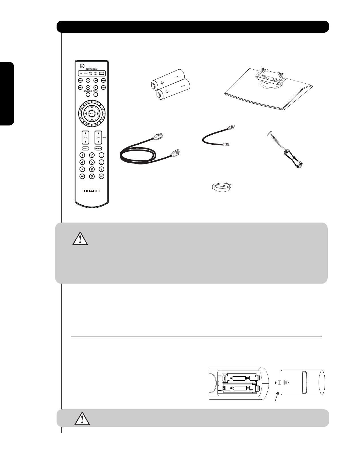
Accessories
Check to make sure you have the following accessories before disposing of the packing material.
쐃
Remote Control
쐇
Two “AA” size,
1.5V batteries
쐋
Power Swivel Table
Top Stand (included)
First time use
쐏
Power Cord
For U.S. models:
For optional accessories, please access our web site at: www.hitachi.us/tv
CAUTION: 1. Ceiling mounting is not recommended. Mounting the panel on the ceiling does not
provide adequate ventilation for the electronics or proper support for the front glass
panel. This plasma television product is designed for a maximum tilting angle of 45
degrees from vertical.
2. This stand for use only with Hitachi P50V701. Use with other apparatus is
capable of resulting in instability causing possible injury.
3. The wall mount unit for the 50" model is WM07S. Please see page 7 for important
related to the wall mount. Wall Mount unit is an optional accessory (Not Included).
쐄 Power Swivel Cable
Wire clamp
쐆
쐂
Two IR Blaster Cables
쐄
쐃 Remote Control Unit CLU-4374A
(Part No. HL02404).
쐇 Two "AA" size, 1.5V batteries.
쐋 Power Swivel Table Top Stand
(Part No. QJ03754)
쐏 Power Cord (P# EV01841).
REMOTE CONTROL BATTERY INSTALLATION AND REPLACEMENT
1.
Open the battery cover of the remote control by pushing down and sliding the back cover off.
2.
Insert two new “AA” size batteries for the remote contr
springs and lift them out.
3. Match the batteries to the (+) and (-) marks in the battery
compartment.
4.
Insert the bottom of the battery
compartment first, push towards the springs and insert the
top of the battery
battery into the battery compartment.
5. Replace the cover.
4
, the (+) side, into place. Do not for
CAUTION: Do not insert batteries with ‘+’ and ‘-’ polarities reversed as this may cause the batteries
to swell or rupture resulting in leakage.
, the (-) side, into the battery
Power Swivel Cable (Part No. EW08433).
쐂
Two IR Blaster cables (P# EY01641).
쐆
Wire clamp
ol. When r
ce the
eplacing old batteries, push them towards the
Bottom View (Remote Control)
Lift up on tab to r
emove back cover.
Page 5
How To Set Up Your New Hitachi Plasma Television
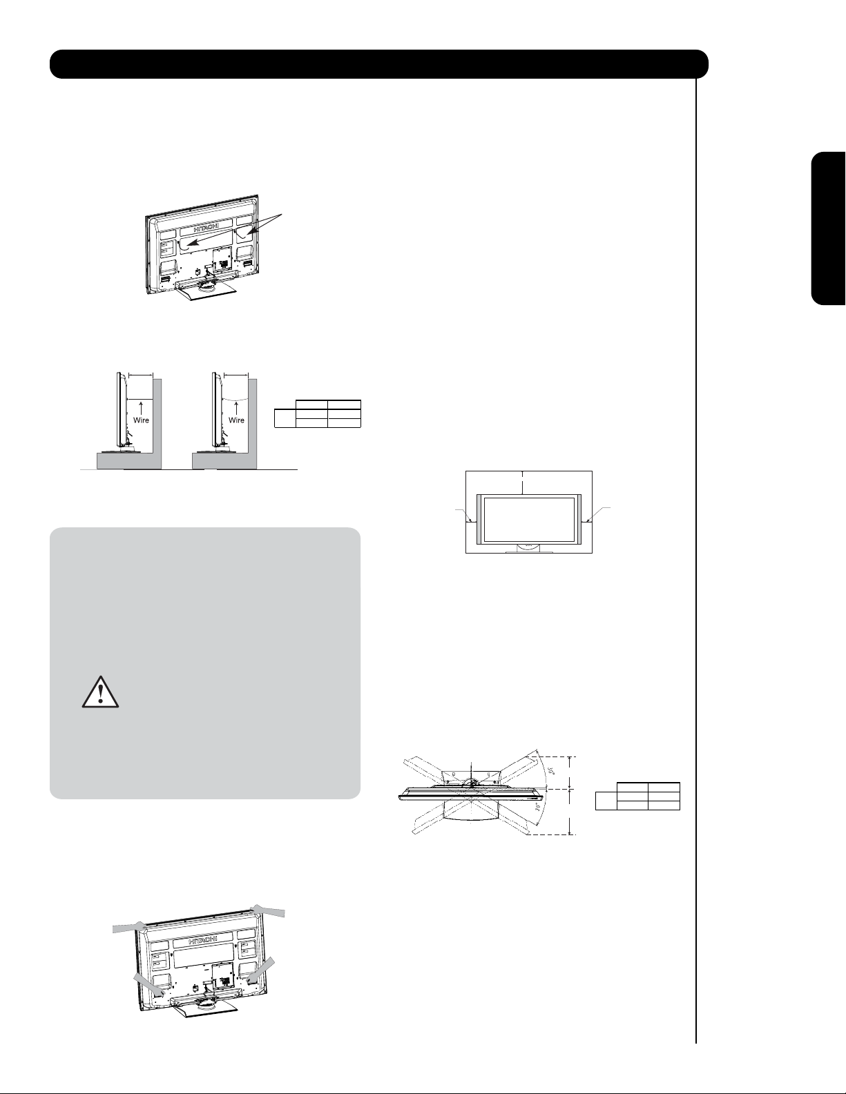
To take measures to prevent the Plasma Television from tipping over and prevent possible injury
it is important to mount the unit in a stable and flat surface.
Securing to a Wall
1. Using metallic wire (two places) fasten the set to
the clamping screw on the rear of the Plasma
TV as shown below.
Wire
2. Keep the Plasma television 4 inches away from the
wall except when mounted using the wall mount
bracket.
3. Secure the television to the wall as shown.
A
(a) Power Swivel
NOT USED
B
(b) Power Swiv el
USED
A B
50"
4 in.
10 cm
12 in.
30 cm
* Please adjust the wire length to avoid
touching the wall when turning the TV.
NOTES: 1. Do not block the ventilation holes of the
Plasma Television. Blocking the ventilation
holes might cause fire or defect.
2. In case of an abnormal symptom, unplug
the AC cord.
3. If you purchased the wall mount bracket
option, please ask for professional installer.
Do not install by yourself.
4. Install the unit at a proper area where it does
not expose anyone to any danger of hitting
themselves (for example their hands, head
or face, etc.) against the edge of the unit and
cause personal injury.
5. If the Power Swivel feature will not be
used, the Plasma television should be
secured to the wall as shown in fig. (a).
6. If the Power Swivel feature will be used,
the Plasma television should be secured
to the wall as shown in fig. (b).
Caution when moving the main unit
As this product is heavy, whenever it is moved, two
people are required to transport it safely. Whenever the
unit is moved it should be lifted forward using the top
and base on both sides of the Television for stability.
When moving the Television, lift the handles , then
support the top frame as shown below.
ANTENNA
Unless your Plasma Television is connected to a cable
TV system or to a centralized antenna system, a good
outdoor color TV antenna is recommended for best
performance. However, if you are located in an
exceptionally good signal area that is free from
interference and multiple image ghosts, an indoor
antenna may be sufficient.
LOCATION
Select an area where sunlight or bright indoor
illumination will not fall directly on the picture screen.
Also, be sure that the location selected allows a free
flow of air to and from the perforated back cover of the
set. In order to prevent an internal temperature
increase, maintain a space of 10 cm (4 inches) from the
sides/back of the Television, and 30 cm (12 inches)
from the top of the television to the ceiling. To avoid
cabinet warping, cabinet color changes, and increased
chance of set failure, do not place the TV where
temperatures can become excessively hot, for
example, in direct sunlight or near a heating appliance,
etc.
30 cm (12 inches)
10 cm (4 inches)
10 cm (4 inches)
CONNECT POWER SWIVEL CABLE
Connect one end of cable to the swivel slot of the
Plasma Rear Panel. Connect the other end to swivel
slot of the Table Top Stand. For more detail information,
please refer to next page installation instruction.
TURNING ANGLE
The maximum turning angle is 30° (left and right). Do
not place any objects on the path of the monitor when
using the power swivel feature.
C
CD
10.8 in.
27.5 cm
15.35 in.
39 cm
50"
D
First time use
50”
5
Page 6
How to set up your new HITACHI Plasma Television
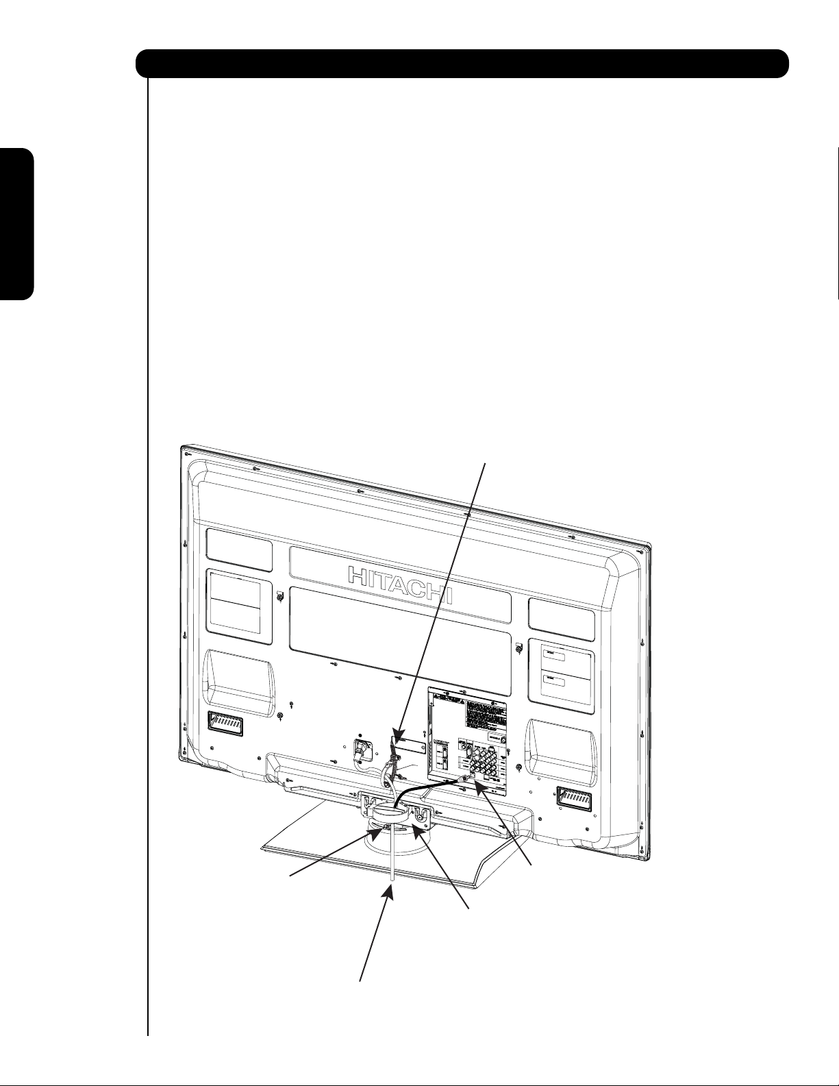
AC CORD AND POWER SWIVEL CABLE INSTALLATION INSTRUCTION
The AC cord and power swivel cable provided with your new Plasma Television need to be installed correctly
to avoid their disconnection when rotating the TV on its Table top stand.
Located on the back of the TV are 2 plastic clamps to hold the AC cord and power swivel cable. Please follow
the instructions below.
쐃
Pass the AC cord through Clamp #1 and connect
it to the TV. Pull on the clamp to tighten the
AC cord to the TV.
쐇
First time use
Connect power swivel cable on one end to the
swivel slot of the Plasma Rear Panel. Connect
the other end to the swivel slot of the Table
Top Stand Base.
The AC cord, power swivel cable and the signal
쐋
cables can all be held together with Clamp #2
(included on the accesories bag).
Clamp #1 : Pass theAC cord through this clamp ;
쐃
then pull the clamp to tighten the AC
cord to the TV.
Swivel slot on Table Top
쐇
Stand Base.
6
AC CORD
Swivel slot on Plasma Rear Panel.
쐇
Clamp #2: Use this clamp to hold the AC cord, power
쐋
swivel connector and the signal cables.
Please assemble this Clamp on the middle
hole of the base metal.
Page 7
How to set up your new HITACHI Plasma Television
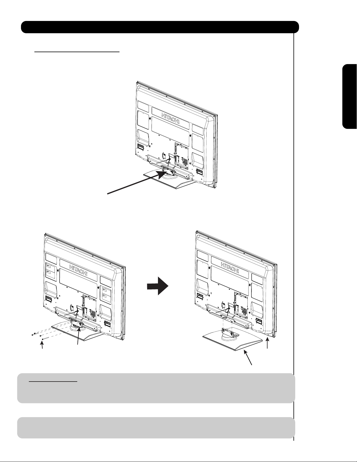
SETTING FOR WALL MOUNTING
STEP (1) :
Please locate the STAND METAL on the back of the TV . This metal is use to hold the TV and the Base ; so it needs
to remove 4 screws from the STAND base in order to separate the TV from the Base.
STAND METAL
First time use
STEP (2):
Please remove the 4 screws of the STAND metal from the TV, now the TV STAND can be separated from the TV.
For dimensions of the WALL MOUNT assembly please refer to page 84.
4 SCREWS
For Model P50V701
CAUTION- This Plasma Display Panel for use only with Hitachi WM07S Wall Mount. Use with other
STAND METAL
TV STAND BASE
Wall Mount is capable of resulting in instability causing possible injury.
NOTE: Use the specified WALL MOUNT unit for the Plasma TV depending on the size of your TV.
Please access our web site at: www.hitachi.us/tv for recommended accessories for your tv.
7
Page 8
How to set up your new HITACHI Plasma Television
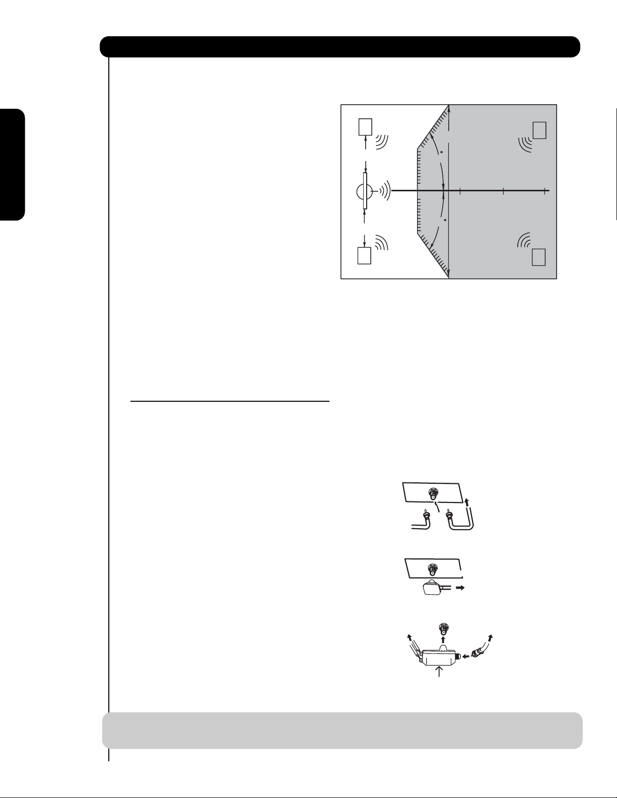
VIEWING
The best picture is seen by sitting directly in front of
the TV and about 10 to 18 feet from the screen.
During daylight hours, reflections from outside light
R
S
may appear on the screen. If so, drapes or screens
can be used to reduce the reflection or the TV can
be located in a different section of the room.
4" Minimum
70
BEST
HORIZONTAL
If the TV’s audio output will be connected to a Hi-Fi
First time use
system’s external speakers, the best audio
performance will be obtained by placing the
speakers equidistant from each side of the receiver
cabinet and as close as possible to the height of
4" Minimum
5'
10'
VIEWING ANGLE
70
15' 20'
the picture screen center. For best stereo
separation, place the external speakers at least
four feet from the side of the TV, place the surround
L
S
speakers to the side or behind the viewing area.
Differences in room sizes and acoustical
environments will require some experimentation
with speaker placement for best performance.
ANTENNA CONNECTIONS TO REAR JACK
PANEL
VHF (75-Ohm) antenna/CATV (Cable TV)
When using a 75-Ohm coaxial cable system, connect CATV coaxial cable to the AIR/CABLE (75-Ohm) terminal.
Or if you have an antenna, connect the coaxial cable to the same AIR/CABLE terminal.
AIR / CABLE
To CATV cable
VHF (300-Ohm) antenna/UHF antenna
When using a 300-Ohm twin lead from an outdoor
antenna, connect the VHF or UHF antenna leads to
screws of the VHF or UHF adapter. Plug the adapter
To outdoor antenna
or
into the antenna terminal on the TV.
AIR / CABLE
When both VHF and UHF antennas are
connected
Attach an optional antenna cable mixer to the TV
antenna terminal, and connect the cables to the
antenna mixer. Consult your dealer or service store for
the antenna mixer.
To UHF
antenna
AIR / CABLE
Antenna Mixer
To outdoor VHF
or UHF antenna
To outdoor antenna
or CATV system
NOTE: Connecting a 300-Ohm twin lead connector may cause interference. Using a 75-Ohm coaxial
cable is recommended.
8
Page 9
How to set up your new HITACHI Plasma Television
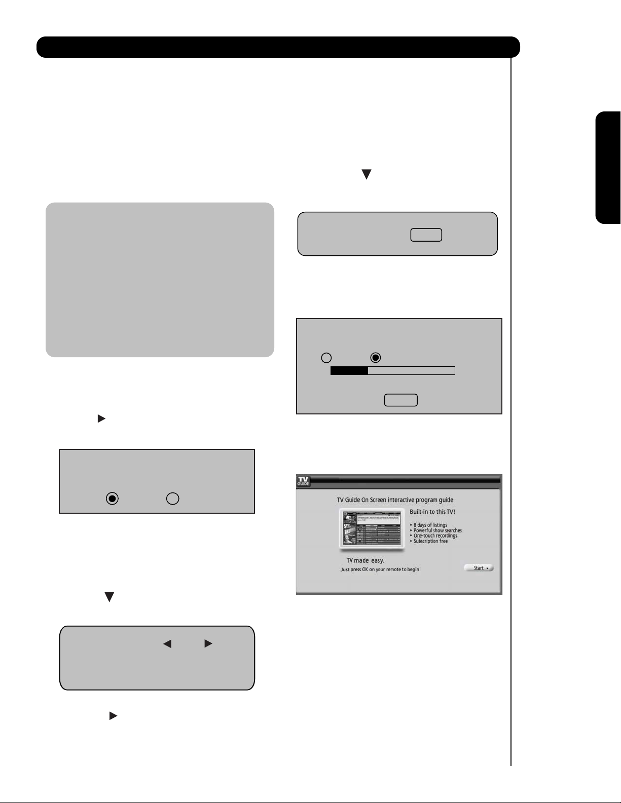
TV SETUP WIZARD
This television has a TV Guide On ScreenTM feature which has the ability to show you a customized list of the
programs and channels available in your area. The information for the guide is broadcast on different channels
in different areas.
Please use this TV Setup Wizard to help the TV Guide On Screen
your area.
TM
find the channels with the information for
First time use
The TV Setup Wizard automatically starts the first
time the TV is turned on.
Note:
1. If you see this screen when you turn on your TV for
the first time and did not yet connect your external
devices and cables to your TV, turn off your TV,
unplug the power cord and connect your devices
and cables according to the applicable connections in
the “First Time Use” section of this Operating Guide.
2. After performing TV Setup Wizard operation, this
page will not appear again. For updating and
adding the channels available in your area refer
to the Auto Channel Scan feature on page 55.
If this is the first time you have turned on your TV and the
TV Setup Wizard appear on-screen, start by selecting Yes
or No in the top portion of the TV Setup Wizard.
1. Use the CURSOR to select Yes or No and press the
SELECT button on the remote control.
Do you want the TV to find all of the channels
for the TV Guide On Screen
TM
?
4. Press the CURSOR to move to the next
window to start the Auto Channel Scan.
Auto Channel Scan : Start
5. Press the SELECT button on the remote
control to begin scanning.
Air
Scanning Channel Number :
12
Analog Digital 12-123
Scan time may take 10 to 20 minutes
Cancel
When Auto Channel Scan is done the TV Guide On
TM
Screen
Setup page will appear (refer to page 52).
Yes No
If Yes is selected proceed to step 2.
If No is selected, press the EXIT button on the remote
control and the TV Guide ON Screen
TM
Setup page will
appear ( refer to page 52).
2. Press the CURSOR to move to the next window to
select the source.
Source: Air
Please connect the antenna or cable
To the input labeled “Air/Cable”.
3. Press the CURSOR to select Air, Cable(1) or
Cable(2).
9
Page 10
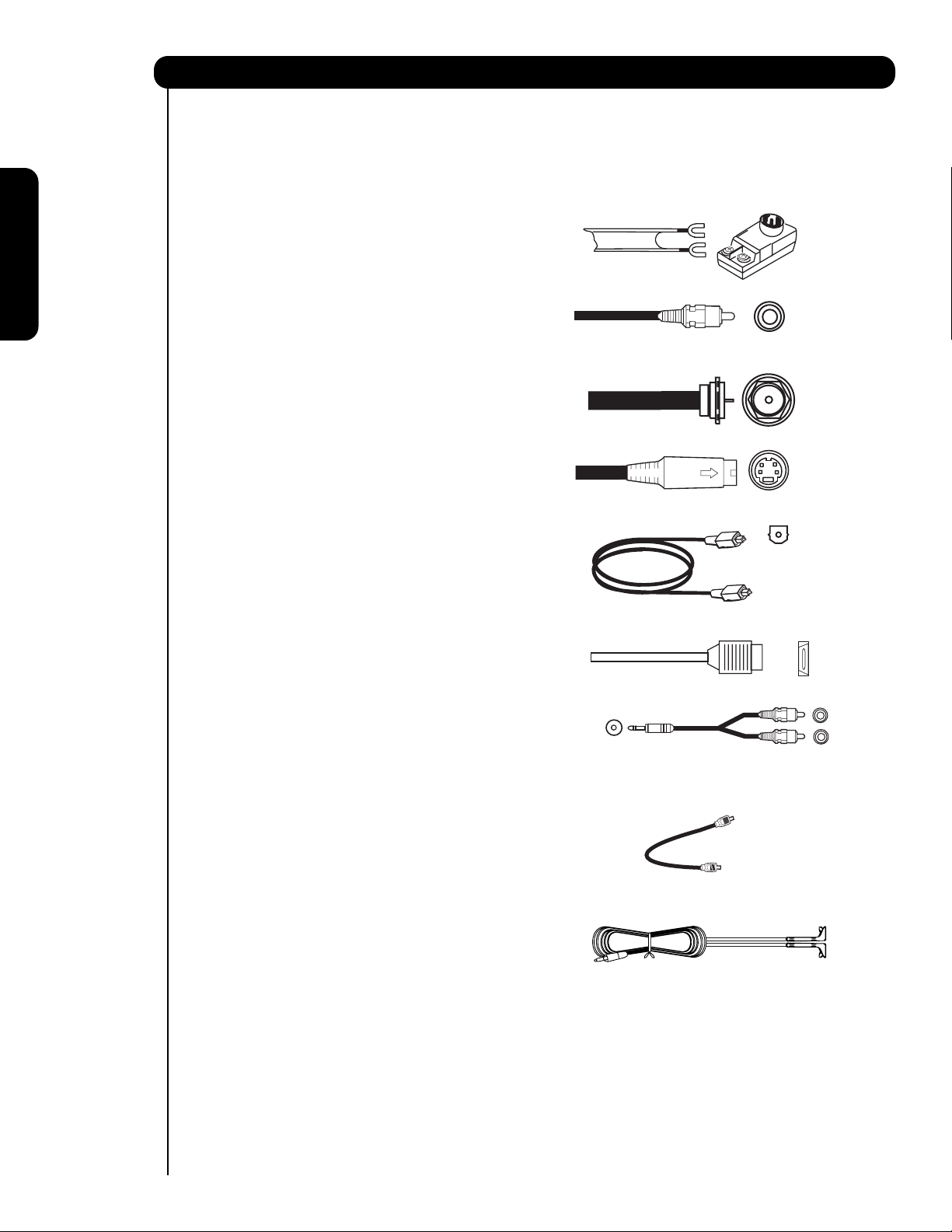
Hook-up Cables and Connectors
Most video/audio connections between components can be made with shielded video and audio cables that have
phono connectors. For best performance, video cables should use 75-Ohm coaxial shielded wire. Cables can be
purchased from most stores that sell audio/video products. Below are illustrations and names of common
connectors. Before purchasing any cables, be sure of the output and input connector types required by the
various components and the length of each cable.
300-Ohm Twin Lead
Cable
This outdoor antenna cable must be connected to an
antenna adapter (300-Ohm to 75-Ohm).
Phono or RCA
Cable
Used on all standard video and audio cables which
First time use
connect to inputs and outputs located on the
television’s rear jack panel and front control panel.
“F” Type 75-Ohm Coaxial Antenna
For connecting RF signals (antenna or cable TV) to the
antenna jack on the television.
S-Video (Super Video) Cable
This connector is used on camcorders, VCRs and laserdisc players with an S-Video feature in place of the
standard video cable to produce a high quality picture.
Optical Cable
This cable is used to connect to an audio amplifier with
an Optical Audio In jack. Use this cable for the best
sound quality.
HDMI Cable
This cable is used to connect your external devices
such as Set-Top-Boxes or DVD players equipped with
an HDMI output connection to the TV’s HDMI input.
Stereo Cable (3.8mm plug to 3.5mm plug)
Used on all standard video and audio cable which
connect to inputs and outputs located on the rear jack
panel and front control panel.
Power Swivel Cable (Provided)
This cable is used to connect the swivel stand to the
rear panel of the Plasma Television.
IR Blaster Cable (Provided)
Connect the IR Blaster to the IR output of your Plasma
Television when AV Net, IR Passthru or G-LINK
TM
feature
are used. You must place the IR Blaster in front
of the corresponding IR window of your cable box
VCR, Set-Top-Box, or other supported equipment.
AUDIO OUT
3.8mm
STEREO
MINI-PLUG
2
RCA TYPE
PLUGS
10
Page 11
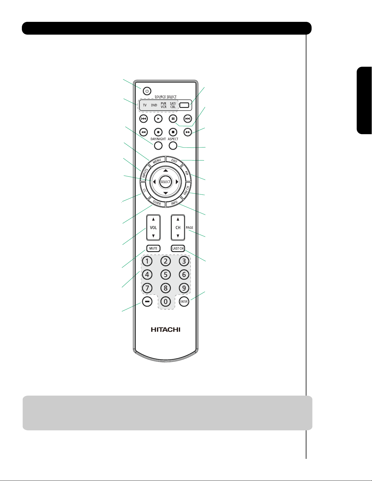
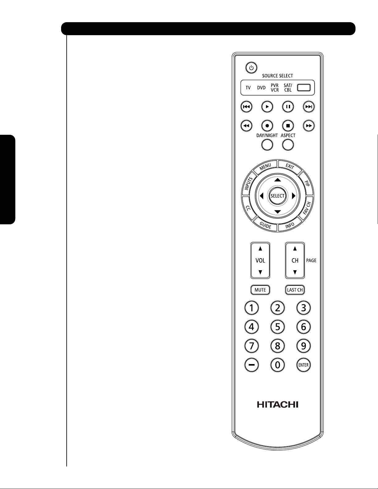
Quick Reference Remote Control Buttons and Functions
In addition to controlling all of the functions on your HITACHI Plasma TV, the new remote control is designed to
operate different types of devices, such as, DVD Players, CBL (Cable Boxes), set-top-boxes, satellite receivers,
and VCRs. The remote control must be programmed to control the chosen device. Please see pages 26-42 for a
complete description of all features and programming of the Remote Control.
(TV, DVD, SAT/CBL,PVR/VCR)
Turns the selected device on and o.
Turns on or blinks to show remote control
mode when the SOURCE ACCESS buttons
are pressed.
Toggles picture mode settings
between DAY and NIGHT mode.
(TV,DVD,SAT/CBL,PVR/VCR)
Accesses the OSD menu system.
Accesses the INPUTS menu system.
CURSOR PAD/SELECT BUTTON
(TV, DVD, SAT/CBL,PVR/VCR)
The Cursor Pad is used as a cursor to navigate
through the OSD and INPUT menu systems.
The Select button is used to Select/Activate
highlighted menu items.
Closed Caption (CC) BUTTON
Press to show and change the
Closed Caption mode.
Accesses the program guide of TV
Increase up and decrease down to adjust
the audio level of your TV.
Reduces the audio level to 50% if pressed
once, and to complete mute if pressed
twice. Press it a third time to restore audio
level.
Used to manually enter the TV channel, and used
for numeric entry when navigating through the
the OSD, INPUTS.
The (-) button is used when the remote is in
Set-Top-Box (STB) mode or when the TV uses a
digital input.
(TV, DVD, SAT/CBL, PVR/VCR)
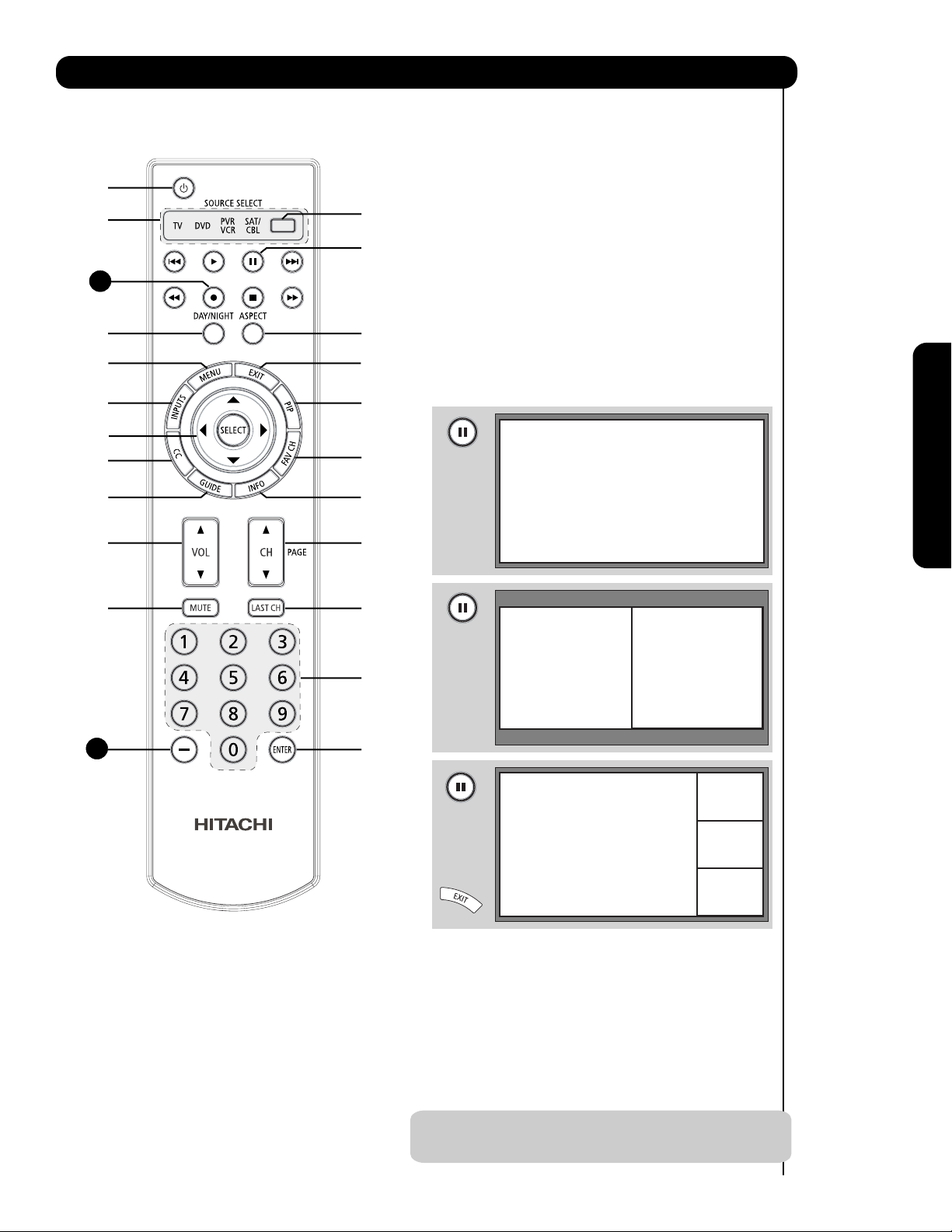
POWER BUTTON
MODE INDICATOR
DAY/NIGHT BUTTON
MENU BUTTON
INPUTS BUTTON
GUIDE BUTTON
(TV, SAT/CBL, PVR)
and other devices.
VOLUME BUTTONS
MUTE BUTTON (TV)
NUMERIC BUTTONS
(TV)
(TV)
(TV)
(TV )
(-) BUTTON
(TV,STB)
SOURCE ACCESS BUTTONS
(TV, DVD, PVR/VCR, SAT/CBL)
Changes the mode of the Universal Remote
Control to control the device selected.
PAUSE BUTTON
(TV, PVR/VCR, DVD)
Press to show and change the Freeze mode of the TV.
Also used to pause other devices when the remote is in
DVD or PVR/VCR.
DVD/VCR CONTROL BUTTONS
(DVD, PVR/VCR)
Controls the functions of your VCR and DVD.
ASPECT BUTTON
(TV)
Changes the aspect ratio of the TV.
EXIT BUTTON
(TV, SAT/CBL, PVR/VCR)
Exits out of the OSD, INPUTS menu
systems if their menu is displayed.
PIP CONTROL BUTTON
(TV)
Press to show and change the Picture-in-Picture mode.
FAVORITE CHANNEL
(FAV CH) button (TV)
Press to enter/access Favorite Channel (FAV CH) mode.
(Favorite channel is only available for TV mode.)
INFO BUTTON
(TV, STB, CBL, PVR)
Displays various information on the
screen, such as channel information.
CHANNEL UP & DOWN BUTTONS
(TV, CBL, STB, PVR/VCR)
Changes up or down the channel.
LAST CHANNEL BUTTON
(TV, SAT/CBL, PVR)
Switches between the current and last channel viewed.
ENTER BUTTON
(TV, VCR, SAT/CBL)
Press to use as SELECT feature.
First time use
LEGEND
TV – Television PVR – Video Recorder/Player
CBL – Cable Box DVD – Digital Video Disc Player
SAT – Satellite
VCR – Videocassete Recorder
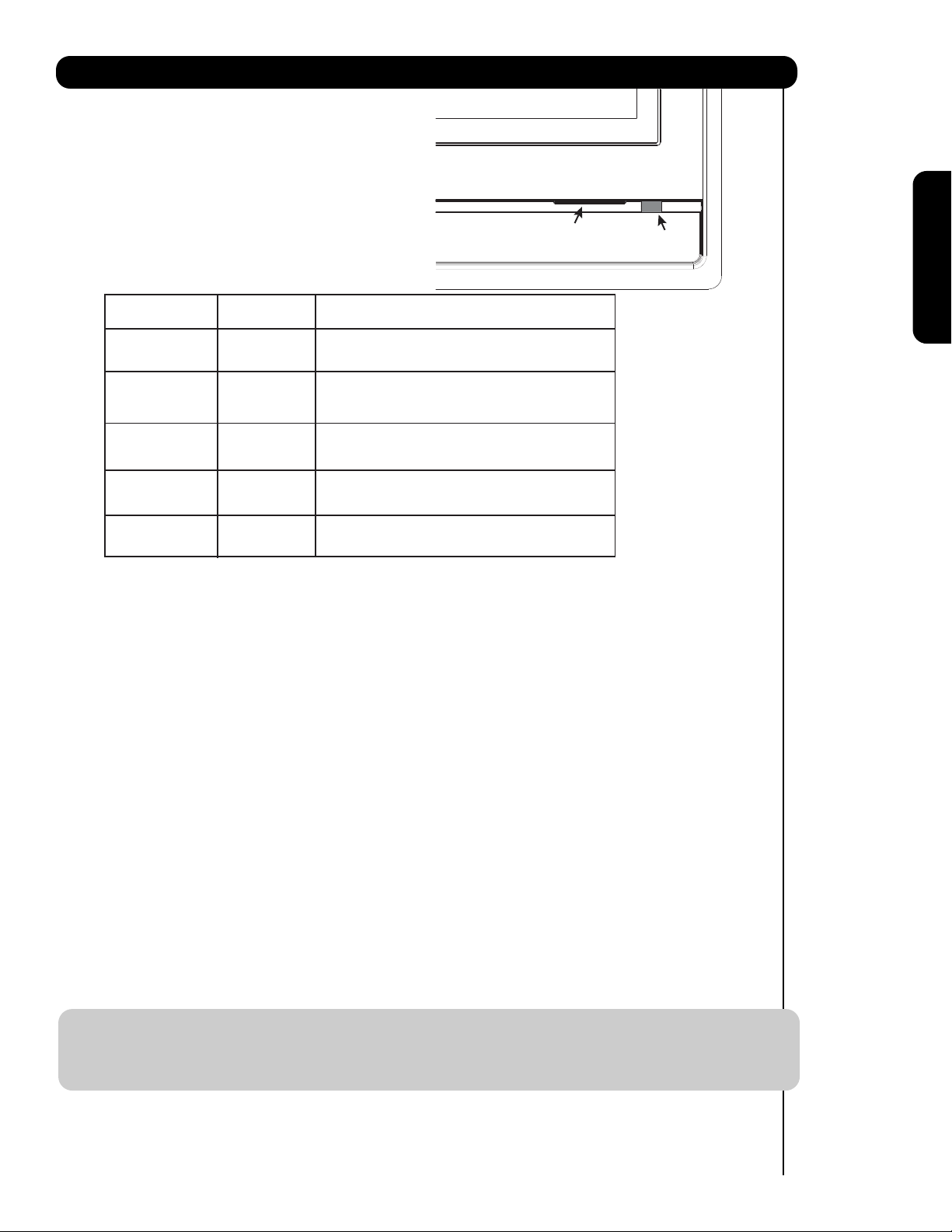
NOTES: 1. The TV’s remote control sensor is located on the right bottom portion of the TV screen. To
control TV functions, please point the remote control directly at the remote control sensor for
best results.
2. VCR precode is included in the PVR mode.
11
Page 12
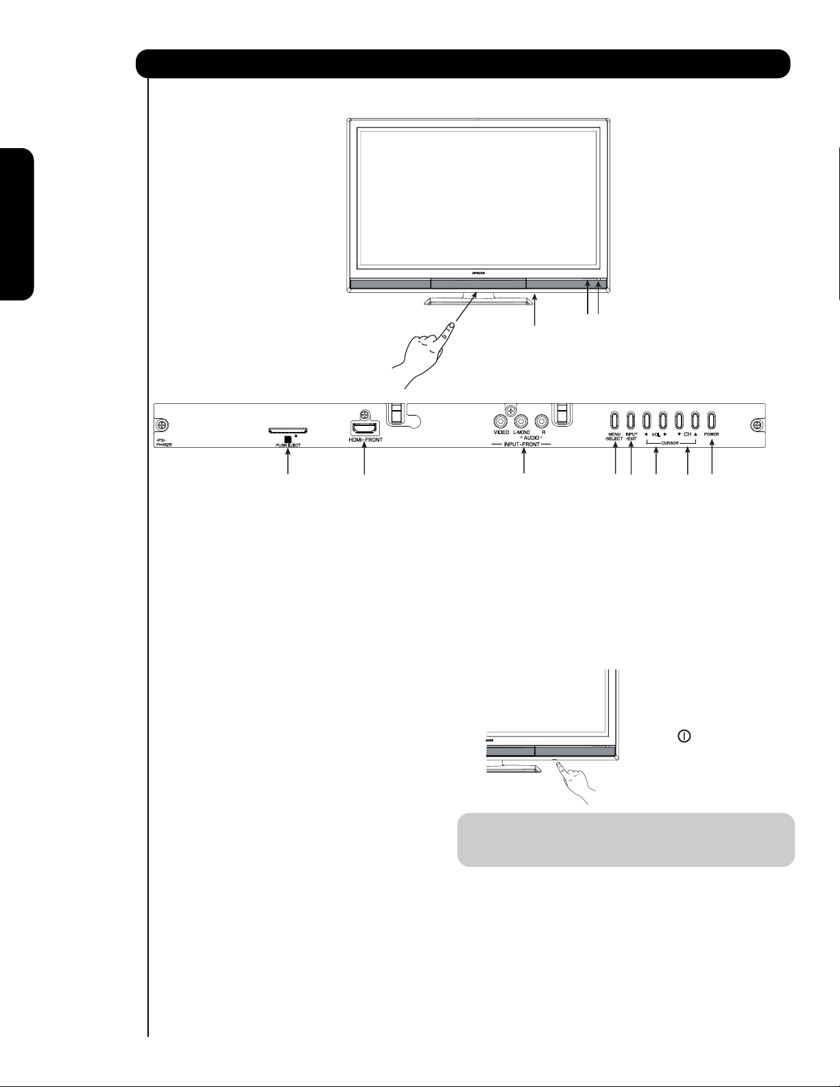
Front Panel Controls
FRONT VIEW
First time use
햺
햻
PUSH TO OPEN CONTROL DOOR
PHOTO INPUT
PUSH EJECT
햸
FRONT PANEL CONTROLS
햹
햲 FRONT POWER button
Press this button to turn the Plasma Television
ON/OFF. It can also be turned ON/OFF by remote
control. The “MAIN POWER” button must be at
stand-by mode.
햳 MENU/SELECT button
This button allows you to enter the MENU, making
it possible to set TV features to your preference
without using the remote. This button also serves
as the SELECT button when in MENU mode.
햴
HDMI-FRONT
Use the front HDMI input for external devices such
as Set-Top-Boxes or DVD players equipped with an
HDMI output connection (see page 16 for reference).
햵 INPUT/EXIT button
Press this button to access the INPUT menu.
Press again to exit the MENU mode.
햴
햳
햷
햽
햸 POWER button
Television MAIN POWER button
This power button is for the complete system, and
must be turned ON/OFF manually. It is
recommended to leave the “MAIN POWER” to ON
condition (lights red) for stand-by mode.
햵
햶
햲
The Main Power
button is located
on the broadside
bottom, under the
mark " ".
NOTE: When the “MAIN POWER” button is set to
OFF or the TV is unplugged, the clock will
stop and may eventually reset itself.
햶 CHANNEL selector
Press these buttons until the desired channel
appears in the top right corner of the TV screen.
These buttons also serve as the cursor down ()
and up () buttons when in MENU mode.
햷 VOLUME level
Press these buttons to adjust the sound level. The
volume level will be displayed on the TV screen.
These buttons also serve as the cursor left () and
right () buttons when in MENU mode.
12
햹
UPGRADE CARD
This card slot is for future software upgrades.
Hitachi will notify you if a software upgrade is
required for your TV. In order to receive written
notification, please complete and return your
warranty card.
햹
SD CARD PHOTO INPUT
To view digital still pictures, please insert a SD
card into the card slot with pictures taken on a
Digital Camera, to view them on the TV screen.
Page 13
Front Panel Controls
햺
POWER light indicator
To turn the TV ON, press the main power
switch located on the lower right side of the
TV. A red stand-by indicator lamp located on
the lower right corner of the front bezel will
illuminate. The Plasma TV is now ready for
remote ON/OFF operation.
Indicating Lamp Power Status Operating
햺
Indicating Lamp
햻
R/C, AV Net
sensor
First time use
Off
Lights
Red
Lights
Blue
Lights
Orange
Blinking
Blue
햻
REMOTE CONTROL sensor
Point your remote at this area when selecting
channels, adjusting volume, etc.
LEARNING AV NET sensor
햻
Point your equipment’s remote control at this area
while using the AV NET Learning Wizard.
INPUT-FRONT JACKS
햽
INPUT-FRONT provide composite Video jacks for
connecting equipment with this capability,
such as a DVD player or Camcorders.
OFF. When the main power switch is set to Off.
OFF.
(Stand-by)
On
Off
(Power Saving)
On
When the main power switch on the TV is ON.
TV MAIN POWER is ON ; picture is shown.
TV MAIN POWER is ON with no signal input
except antenna (no sync. signal).
When TV receives the IR signal from R/C.
NOTES: 1. Your HITACHI Plasma TV will appear to be turned OFF (lights orange) if there is no video input
when INPUT : 1, 2, 3, Front or HDMI : 1, 2, Front is selected. Check the Power Light to make sure
the TV is turned off or in Stand-by mode (lights red) when not in use.
2. Remote Control cannot turn ON/OFF the “MAIN POWER” of the TV.
13
Page 14
Rear Panel Connections
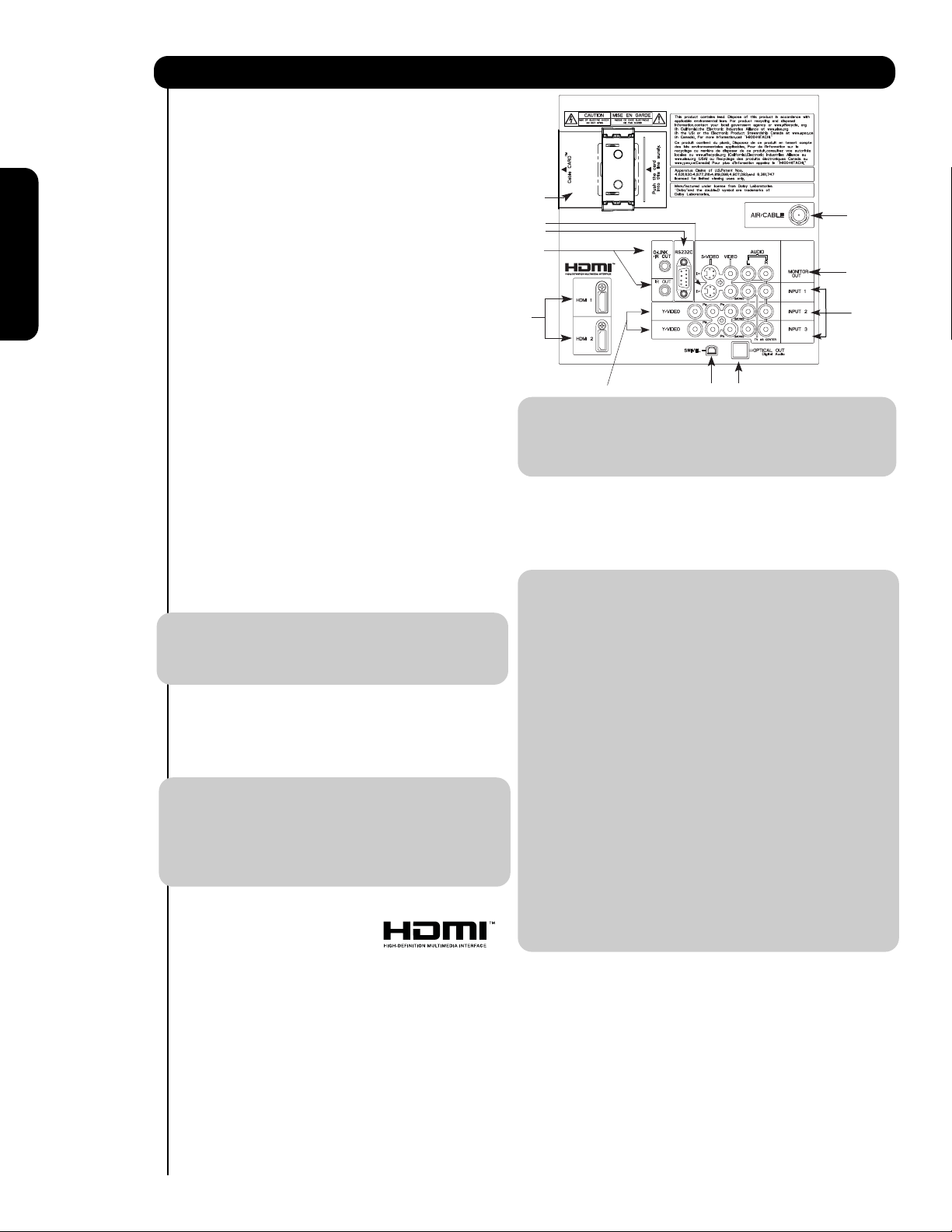
햲 Antenna Input
To switch between Cable and Air input, go to the
Channel Manager option to change the signal
source CABLE or AIR.
햽
햳 Audio/Video Inputs 1, 2 and 3
By using the INPUTS button, the CURSOR PAD (
and ), and the SELECT button or CURSOR PAD
햶
햹
햺
of the remote control, you can select each video
source. Use the audio and video inputs to connect
external devices, such as VCRs, camcorders,
First time use
laserdisc players, DVD players etc. (if you have
햷
mono sound, insert the audio cable into the left
audio jack).
햲
햴
햳
햴 MONITOR OUT & AUDIO OUT
These jacks provide fixed audio and video
signals (CABLE/AIR or INPUTS ) which are
used for recording. Use the S-VIDEO output
for high quality video output. Component signal
to Input 2 and 3, and HDMI inputs will not
have monitor output.
햵 Optical Out (Digital Audio)
This jack provides Digital Audio Output for your
audio device that is Dolby
® Digital and PCM
compatible, such as an audio amplifier.
NOTE: *Manufactured under license from Dolby
Laboratories. “Dolby” and the double-D
symbol are trademarks of Dolby
Laboratories.
햶 S-VIDEO Input 1
Input 1 provide S-VIDEO (Super Video)
jacks for connecting equipment with S-VIDEO
output capability.
NOTE: 1. You may use VIDEO or S-VIDEO inputs to
connect to INPUT 1 , but only one of
these inputs may be used at a time.
2. S-VIDEO output may be used for
recording, only when the input is of
S-VIDEO type.
햷 HDMI 1, 2 (High Definition Multimedia
Interface)
ABOUT HDMI – HDMI is the
next-generation all digital interface for consumer
electronics. HDMI enables the secure distribution
of uncompressed high-definition video and multichannel audio in a single cable. Because digital
television (DTV) signals remain in digital format,
HDMI assures that pristine high-definition images
retain the highest video quality from the source all
the way to your television screen.
Use the HDMI input for your external devices such
as Set-Top-Boxes or DVD players equipped with an
HDMI output connection.
HDMI, the HDMI logo and High-Definition
Multimedia Interface are trademarks or registered
14
trademarks of HDMI Licensing LLC.
햸
햻
햵
NOTE: 1. The HDMI input is not intended for use
with personal computers.
2. Only DTV formats such as 1080p, 1080i, 720p,
480i and 480p are available for HDMI input.
햸 Component: Y-P
INPUTS 2 and 3 provide Y-P
BPR Inputs
BPR jacks for
connecting equipment with this capability, such as
a DVD player or Set Top Box. You may use
composite video signal for both inputs.
NOTE: 1. Do not connect composite VIDEO and
S-VIDEO to INPUT 1 at the same time.
S-VIDEO has priority over VIDEO input.
2. Your component outputs may be labeled
Y, B-Y, and R-Y. In this case, connect the
components B-Y output to the TV’s P
input and the components R-Y output to
the TV’s P
R input.
3. Your component outputs may be labeled
BCR. In this case, connect the component
Y-C
B output to the TV’s PB input and the
C
component C
R output to the TV’s PR input.
4. It may be necessary to adjust TINT to
obtain optimum picture quality when using
the Y-P
BPR inputs (see page 45).
5. To ensure no copyright infringement, the
MONITOR OUT output will be abnormal,
when using the Y-P
BPR jacks and HDMI
Input.
6. INPUT 2 , and 3 (Y/VIDEO) can be used for
composite video and component video
input.
햹 For Special AV control use only.
햺
IR Out / G-LINK
TM
This jack provides IR output to your external components
(VCR, Cable box, DVD player, etc.). This connection
will allow you to control the external components with
your Plasma Television’s remote control.
(For reference see pages 24-25).
햻
Power Swivel Connector
Connect from here the Power Swivel cable (provided)
to the Table Top Stand Base swivel slot.
B
Page 15
Rear Panel Connections
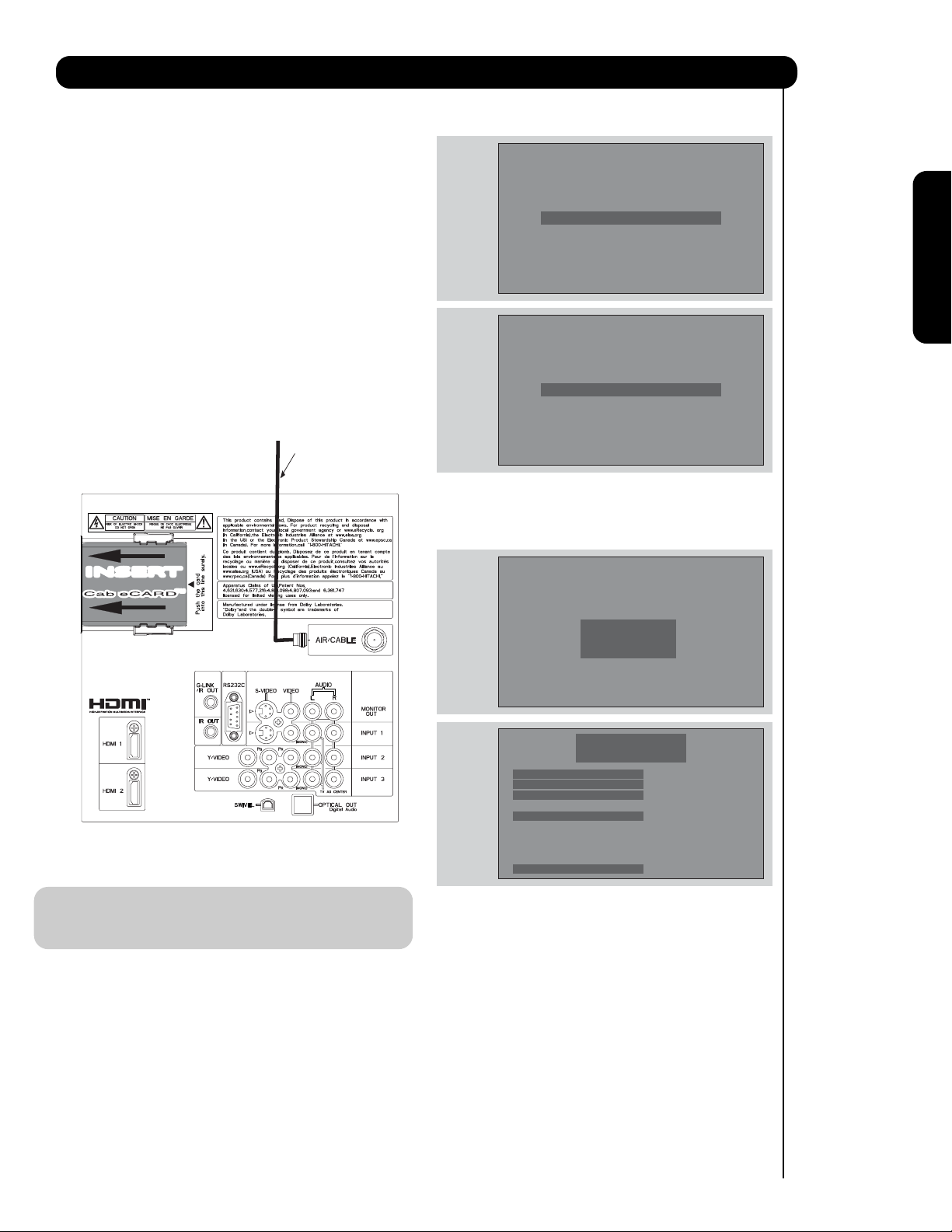
햽 CableCARD Slot
This slot is for the CableCARD that will be provided
by your local cable operator to gain access to
chosen cable channels. The CableCARD will allow
you to tune digital and high definition encrypted cable
programming. Please call your local cable operator if
this service is available before requesting a
CableCARD (also known as Point of Deployment
(POD) module).
If the CableCARD is properly installed or removed, the
TV will display the following respective screens.
First time use
CableCARD is installed
1. Connect a coaxial cable to cable terminal of
the Rear Panel Jacks.
2. Insert the CableCARD into the slot (Top of card
should be facing towards you as shown
below).
Digital Cable Signal
INSERTINSERT
OR
CableCARD is not installed
After the CableCARD is installed, wait until the second
screen below appears.
Acquiring Data.
Please wait.
In order to start cable service
for this device, please contact
your cable provider
CableCARD(tm): 123-456-789-1
Host: 123-456-789-1
Data: 123-456-789-1
Unit Address: 123-456-789-1
NOTE: 1. A digital cable subscription is required.
2. Do not insert a PCMCIA card into the
CableCARD slot.
Press EXIT to return
Please take note of all information on the screen (you
will provide this information to your cable operator).
Call your cable operator and give them the information
from the card to start your cable service.
15
Page 16
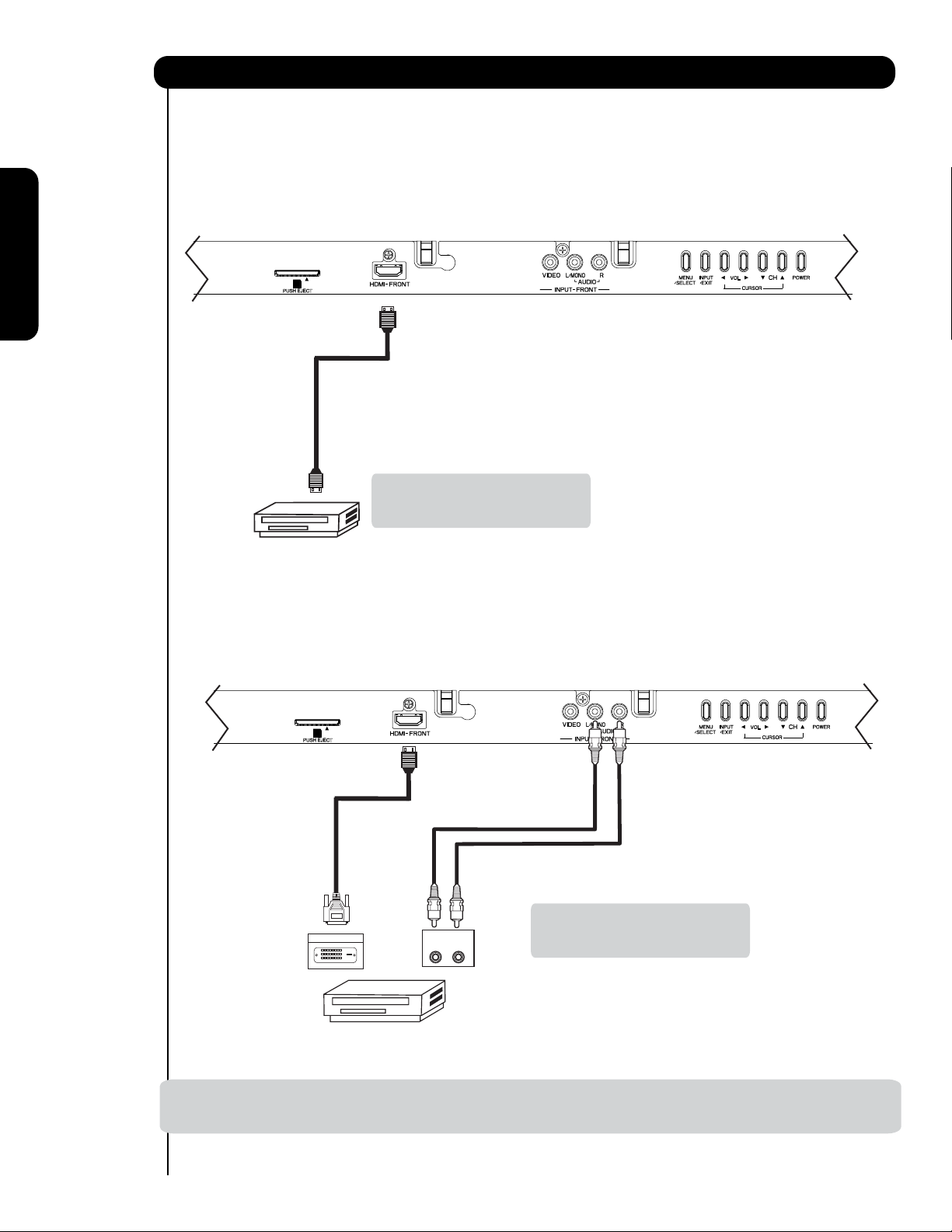
Connecting External Video Sources
The FRONT panel jacks are provided as a convenience to allow you to easily connect HDMI or DVI signals
from a DVD, Set Top Box , Video Game as shown in the following examples (When connecting DVI signal it will
need to connect the audio output into the Front Audio Input jacks) :
A) Connecting HDMI signal.
FRONT INPUT PANEL
PHOTO INPUT
PUSH EJECT
First time use
Note : Special device cables will be
according to the own device
specifications.
HDMI DIGITAL
OUTPUT CAPABILITY
DVD , Set Top Box,
Video Game Console.
B) Connecting DVI signal.
FRONT INPUT PANEL
PHOTO INPUT
PUSH EJECT
DIGITAL OUTPUT
DVI DIGITAL
OUTPUT CAPABILITY
DVD , Set Top Box,
Video Game Console.
DVI to HDMI
Cable
OUTPUT
L R
Back of
HDTV Set-Top-Box or
DVD Player
Note : Special device cables will be
according to the own device
specifications.
NOTE: 1. Completely insert connection cord plugs when connecting to front panel jacks. If you do not, the played back
picture may be abnormal.
16
Page 17
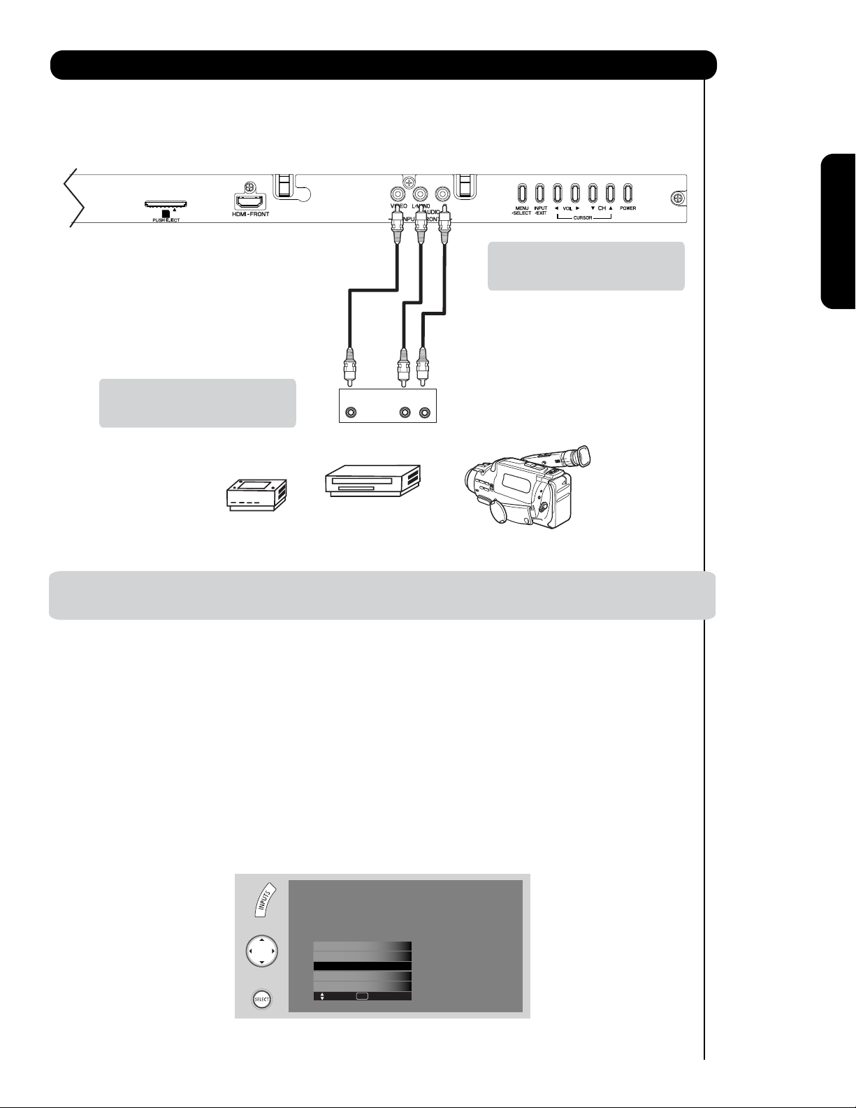
Connecting External Video Sources
The FRONT panel jacks are provided as a convenience to allow you to easily connect a camcorder , DVD, Video
Game and a VCR as shown in the following examples:
FRONT INPUT PANEL
PHOTO INPUT
PUSH EJECT
Note : For Monoaural devices, please
connect Audio signal cable into
L/Mono input jack .
First time use
Note : Special device cables will be
according to the own device
Video
OUTPUT
L R
specifications.
COMPOSITE VIDEO
Video Game
OUTPUT CAPABILITY
DVD , Video Game
Console.
Video Camera
NOTE: 1. Completely insert connection cord plugs when connecting to front panel jacks. If you do not, the
played back picture may be abnormal.
The exact arrangement you use to connect the VCR, camcorder, laserdisc player, DVD player, or HDTV Set
Top Box to your Plasma TV is dependent on the model and features of each component. Check the
owner’s manual of each component for the location of video and audio inputs and outputs.
The following connection diagrams are offered as suggestions. However, you may need to modify them to
accommodate your particular assortment of components and features. For best performance, video and
audio cables should be made from coaxial shielded wire.
Before Operating External Video Source
Connect an external source to one of the INPUT terminals, then press the INPUTS button to show the
INPUTS menu. Use the CURSOR PAD ( and ) to select the Input of your choice. Then press
the SELECT button or the CURSOR PAD to confirm your choice (see page 29).
HDMI-Front
Photo Input
Cable
Air /
Input 1
Input 2
Move SEL Sel.
17
Page 18
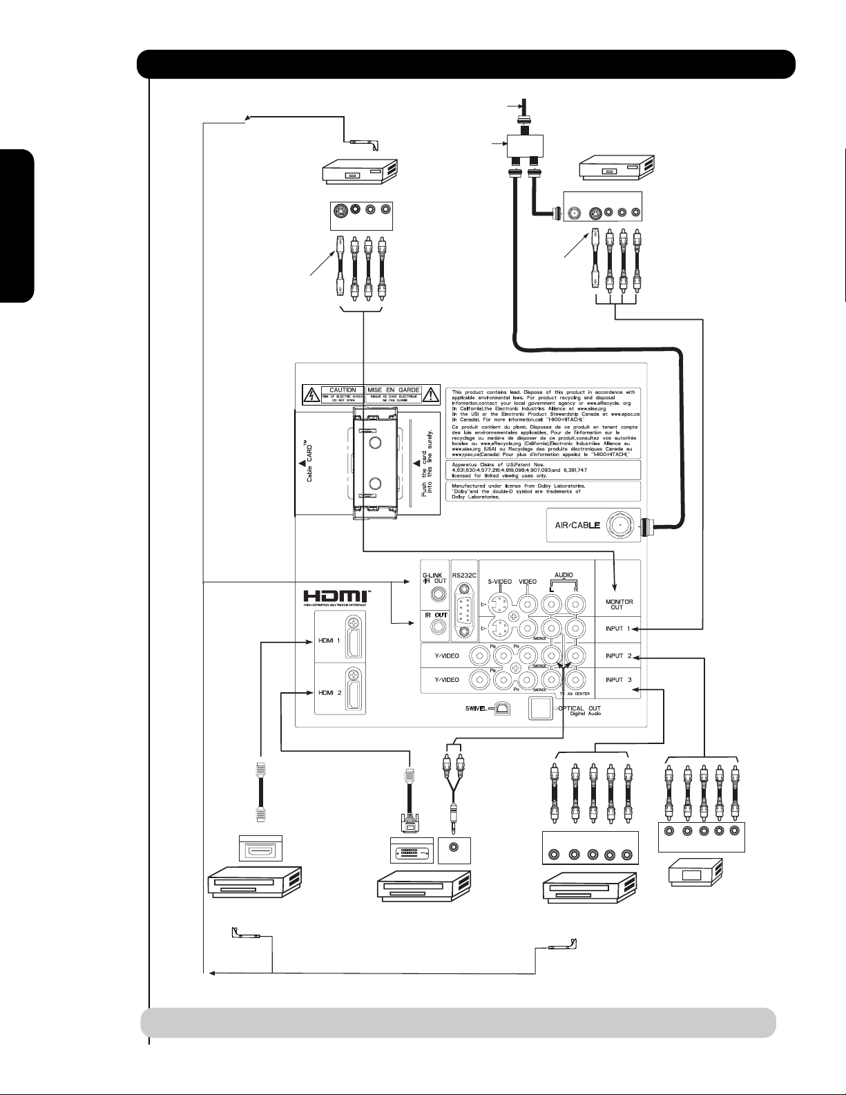
Rear Panel Connections
(IR BLASTER CABLE PROVIDED)
CONNECT TO
G-LINKTM/IR OUT
Outside Antenna
or
Cable TV coaxial cable
2-Way signal splitter
VCR #1
OUTPUT
ANT
IN
VLR
S-VIDEO
S-VIDEO
VCR #2
V L R
INPUT
Optional
First time use
Optional
18
HDMI
to
HDMI
HDMI OUTPUT
HDMI DIGITAL
OUTPUT CAPABILITY
DVI
to
HDMI
DIGITAL OUTPUT
AUDIO OUT
DIGITAL
OUTPUT CAPABILITY
(IR BLASTER CABLE PROVIDED)
CONNECT TO
IR OUT
NOTE: Cables are optional, except when specified.
YP
B/CBPR/CR
DVD Player
OUTPUT
L R
Y P
BPR
OUTPUT
L R
HDTV Set-Top Box
Page 19

Tips on Rear Panel Connections
• S-VIDEO, Y-PBPR, or HDMI connections are provided for high performance laserdisc players, VCRs etc. that
have this feature. Use these connections in place of the standard video connection if your device has this
feature.
• If your device has only one audio output (mono sound), connect it to the left audio jack on (L/(MONO)) the
Rear Panel.
• Refer to the operating guide of your other electronic equipment for additional information on connecting
your hook-up cables.
• A single VCR can be used for VCR #1 and VCR #2, but note that a VCR cannot record its own video or line
output (INPUT: 1 in the example on page 18). Refer to your VCR operating guide for more information on
line input-output connections.
• Connect only 1 component (VCR, DVD player, camcorder, etc.) to each input jack.
• COMPONENT: Y-P
DVD players and set-top-boxes. Use these connections in place of the standard video connection if your
device has this feature.
• Your component outputs may be labeled Y, B-Y, and R-Y. In this case, connect the components B-Y
output to the TV’s PBinput and the components R-Y output to the TV’s PRinput.
• Your component outputs may be labeled Y-C
TV’s P
• It may be necessary to adjust TINT to obtain optimum picture quality when using the Y-PBPRinputs. (See
page 45)
• To ensure no copyright infringement, the MONITOR OUT output will be abnormal, when using the Y-P
HDMI input jacks.
• Input HDMI 1, HDMI 2 or HDMI FRONT can accept HDMI signal.
input and the components CRoutput to the TV’s PRinput.
B
(Input 2 & 3) connections are provided for high performance components, such as
BPR
. In this case, connect the components CBoutput to the
BCR
BPR and
First time use
• S-VIDEO monitor output may be used for recording only when the input is of S-VIDEO type.
• When using a HDMI input from a Set-Top-Box, it is recommended to use a 1080p, 1080i or 720p input signal.
• When HDMI input a 1080p signal, it is recommended that the length of the cable should be less than 5 meters.
INSTALLATION RECOMMENDATION:
1. Video signals fed through a VCR may be affected by copyright protection systems and the picture will be
distorted on the television.
2. Connecting the television directly to the Audio /Video output of a Set-Top-Box will assure a more normal
picture.
19
Page 20
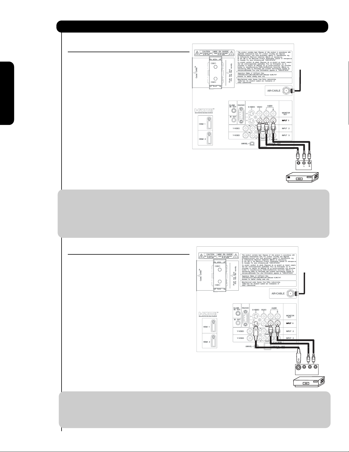
Connecting External Video Sources
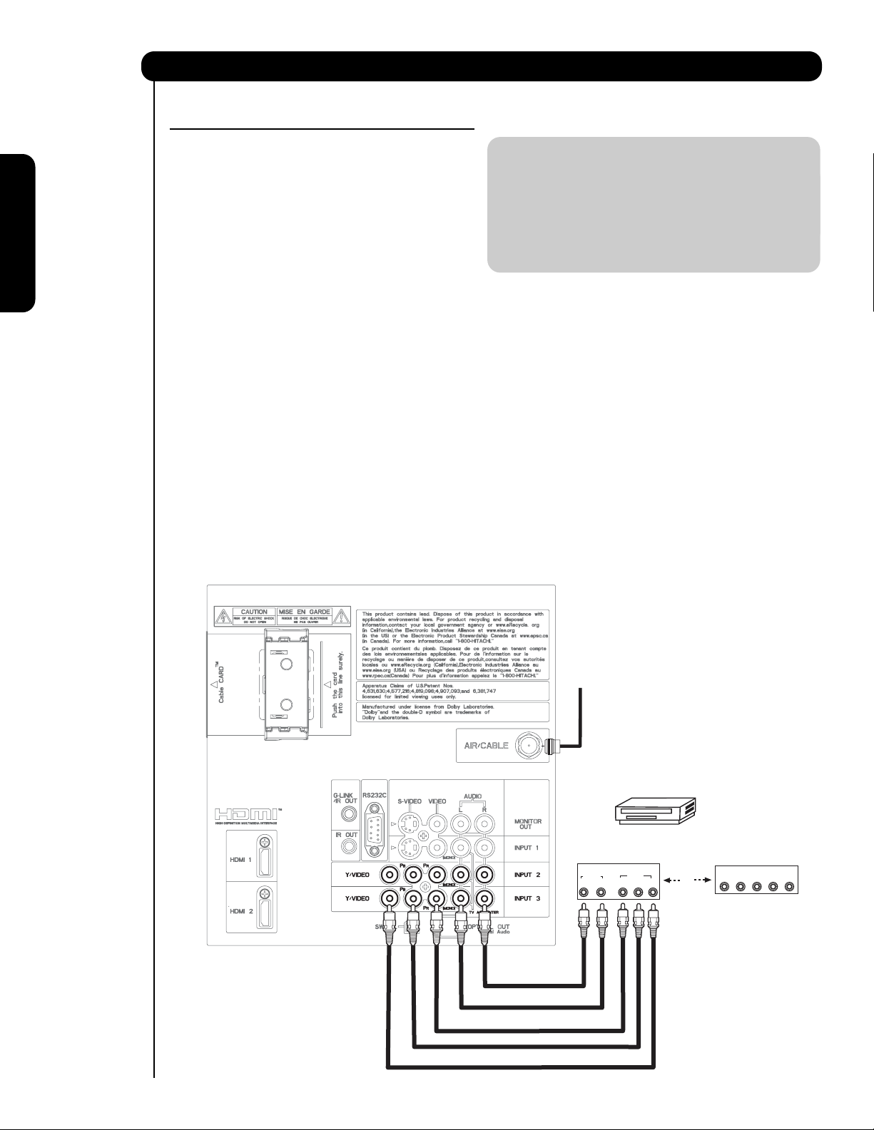
CONNECTING A VIDEO AND STEREO AUDIO
SOURCE TO INPUT1 ~ FRONT INPUT
1. Connect the cable from the VIDEO OUT of the
VCR or the laserdisc player to the INPUT
Cable or
Air signal
(VIDEO) jack, as shown on the Rear Panel to the
right.
2. Connect the cable from the AUDIO OUT R of the
VCR or the laserdisc player to the INPUT
(AUDIO/R) jack.
First time use
3. Connect the cable from the AUDIO OUT L of the
VCR or the laserdisc player to the INPUT
(AUDIO/L) jack.
4. Press the INPUTS button, then select INPUT 1
2,3 or Front from the INPUTS menu to view the
program from the VCR or laserdisc player.
Back of
5. Select CABLE or AIR from the INPUTS menu to
VCR
Video
OUTPUT
return to the last channel tuned.
VCR
NOTE: 1. Completely insert the connection cord plugs when connecting to rear panel jacks. The picture and
sound that is played back will be abnormal if the connection is loose.
2. A single VCR can be used for VCR #1 and VCR #2 (see page 18) but note that a VCR cannot record
its own video or line output. Refer to your VCR operating guide for more information on line inputoutput connections.
3. When INPUT 2 or 3 are used, it is necessary to connect the video output of the device to the
Y/VIDEO input jack of the TV .
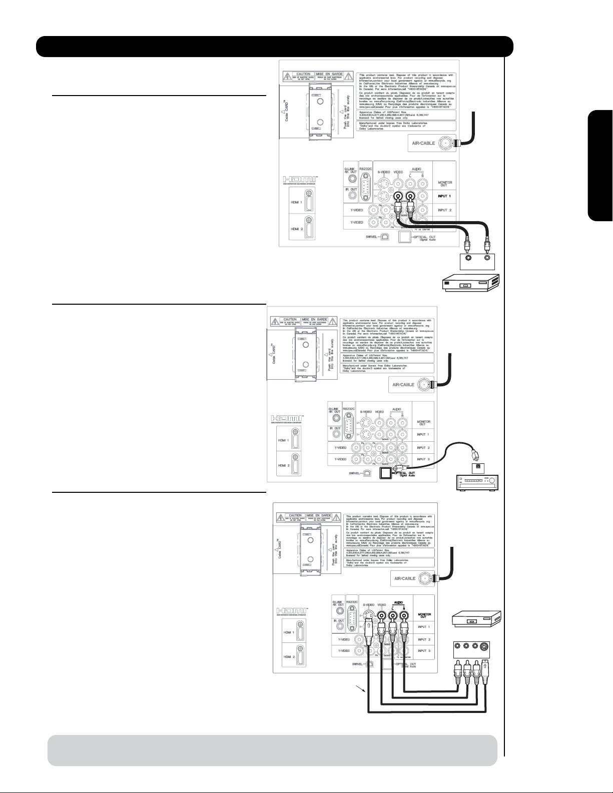
CONNECTING AN S-VIDEO AND STEREO AUDIO
SOURCE TO INPUT 1
1. Connect the cable from the S-VIDEO OUT of
the S-VHS VCR or the laserdisc player to the
Cable or
Air signal
INPUT (S-VIDEO) jack, as shown on the Rear
Panel to the right.
2. Connect the cable from the AUDIO OUT R of
the VCR or the laserdisc player to the INPUT
(AUDIO/R) jack.
3. Connect the cable from the AUDIO OUT L of
the VCR or the laserdisc player to the INPUT
(AUDIO/L) jack.
4. Press the INPUTS button, then select INPUT 1
from the INPUTS menu to view the program
from the VCR or laserdisc player.
5. Select CABLE or AIR from the INPUTS menu to
return to the last channel tuned.
Back of VCR or
Laserdisc Player
Video L R
S-VIDEO
OUTPUT
VCR or Laserdisc Player
NOTE: 1. Completely insert the connection cord plugs when connecting to rear panel jacks. The picture and
sound that is played back will be abnormal if the connection is loose.
2. A single VCR can be used for VCR #1 and VCR #2 (see page 18), but note that a VCR cannot record
its own video or line output. Refer to your VCR operating guide for more information on line inputoutput connections.
20
Page 21
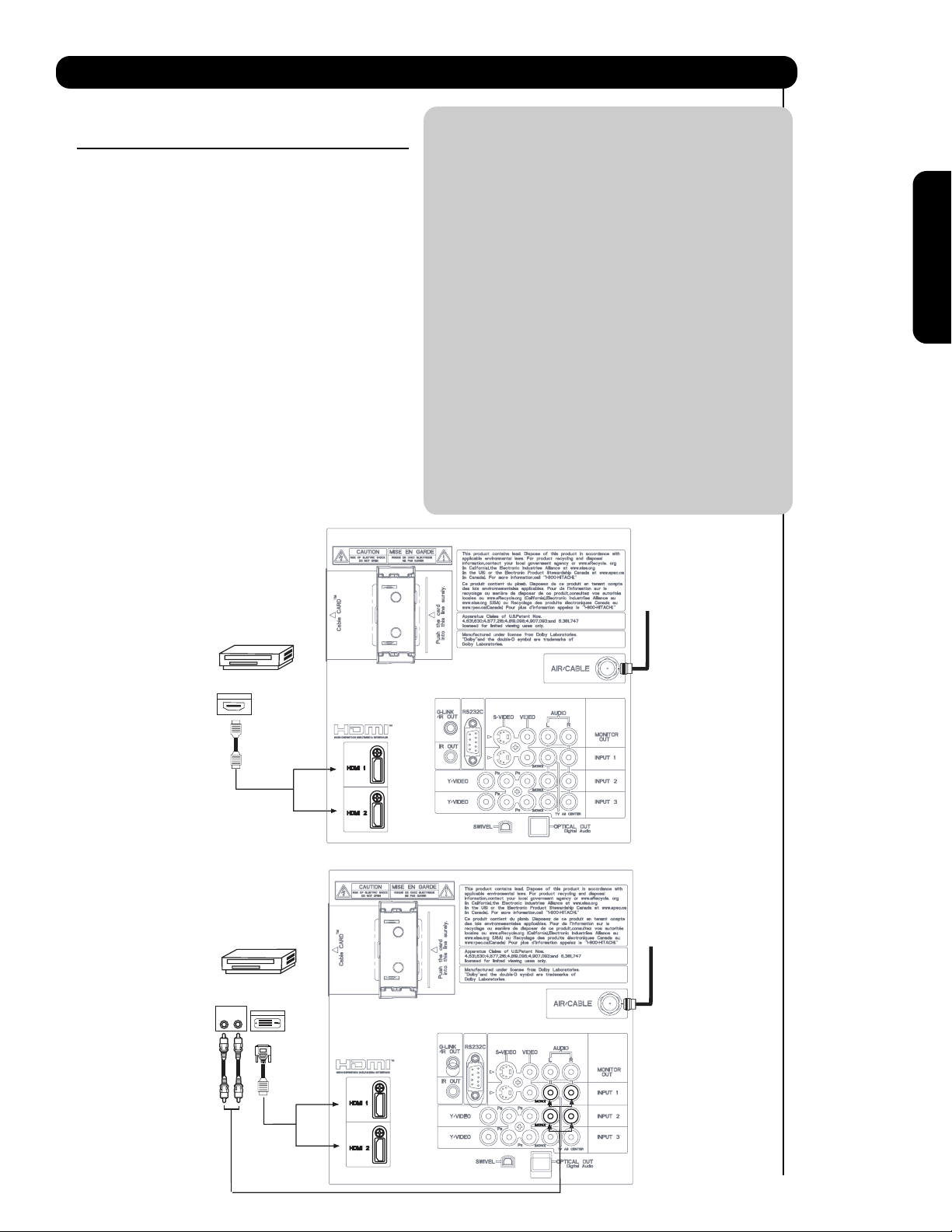
Connecting External Video Sources
CONNECTING A COMPONENT SOURCE WITH HDMI OR
DVI CAPABILITY TO HDMI 1, HDMI 2 OR HDMI FRONT
1. Connect the HDMI or DVI to HDMI connection
cable from the output of the HDTV set top box
or DVD player to the HDMI input as shown
on the Rear panel below.
2. With DVI output, connect the cable from the
AUDIO OUT R of the HDTV set top box or DVD
player to the INPUT (AUDIO/R) jack as shown on
the Rear Panel below.
3. With DVI output, connect the cable from the
AUDIO OUT L of the HDTV set top box or DVD
player to the INPUT (AUDIO/L) jack as shown
on the Rear Panel below.
4. Press the INPUTS button, then select HDMI 1, 2
or FRONT to view the program from the HDTV
SET TOP BOX or DVD player.
5. Select CABLE or AIR from the INPUTS menu to
return to the last channel viewed.
HDMI input
NOTE: 1. Completely insert the connection cord
plugs when connecting to rear panel jacks.
The picture and sound that is played back
will be abnormal if the connection is loose.
2. The HDMI input on HDMI 1 , 2 and FRONT
contains the copy protection system called
High-bandwidth Digital Content Protection
(HDCP). HDCP is a cryptographic system
that encrypts video signals when using
HDMI connections to prevent illegal
copying of video contents.
3. HDMI is not a “NETWORK” technology. It
establishes a one-way point-to-point
connection for delivery of uncompressed
video to a display.
4. The connected digital output device
controls the HDMI interface so proper set-up
of device user settings determines final
video appearance.
5. When using a DVI to HDMI cable, connect the
Audio Out L and R cables at the same INPUT
(1 , 2 or Front) as your HDMI INPUT(1 , 2 or Front).
(For FRONT INPUT see page 16 for reference).
First time use
HDTV Set-Top-Box or
DVD Player
DIGITAL OUTPUT
HDMI
Cable
DVI to HDMI Input
HDTV Set-Top-Box or
DVD Player
Back of HDTV
Set-Top-Box
or DVD Player
OUTPUT
LR
Back of
HDTV Set-Top-Box or
DVD Player
DIGITAL OUTPUT
CABLE
or
Air signal
or
CABLE
or
Air signal
DVI to HDMI
Cable
or
or
21
Page 22
Connecting External Audio/Video Devices
CONNECTING A COMPONENT AND STEREO
AUDIO SOURCE TO INPUT 2 or 3:Y-PBPR.
1. Connect the cable from the Y OUT of the
Laserdisc/DVD player or HDTV set top box to
the INPUT (Y) jack, as shown on the Rear
panel below.
NOTE: 1. Completely insert the connection cord
plugs when connecting to rear panel jacks.
The picture and sound that is played back
will be abnormal if the connection is loose.
2. See page 19 for tips on REAR PANEL
2. Connect the cable from the PB/CBOUT or B-
CONNECTIONS.
Y OUT of the Laserdisc/DVD player or HDTV
set top box to the INPUT (PB)jack.
First time use
3. Connect the cable from the PR/CROUT or RY OUT of the Laserdisc/DVD player or HDTV
set top box to the INPUT (PR) jack.
4. Connect the cable from the AUDIO OUT R of
the Laserdisc/DVD player or HDTV set top box
to the INPUT (AUDIO/R) jack.
5. Connect the cable from the AUDIO OUT L of
the Laserdisc/DVD player or HDTV set top box
to the INPUT (AUDIO/L) jack.
6. Press the INPUTS button, then select INPUT 2
or 3 from the INPUTS menu to view the
program from the Laserdisc/DVD player or
HDTV set top box.
7. Select CABLE or AIR to return to the last
channel tuned.
CABLE
or
Air signal
AUDIO
R
Back of
DVD Player
OUTPUT
PR/CR PB/CB Y
L
DVD Player
VIDEO
OR
OUTPUT
L R Y P
HDTV Set-Top Box
B P
R
22
Page 23
Connecting External Audio/Video Devices
CONNECTING A VIDEO AND MONAURAL AUDIO
SOURCE TO INPUT 1 ~ FRONT INPUT
1. Connect the cable from the VIDEO OUT of the
VCR or the laserdisc player to the INPUT
(VIDEO) jack, as shown on the Rear Panel on the
right.
2. Connect the cable from the AUDIO OUT of the
VCR or the laserdisc player to the INPUT
(MONO)/L(AUDIO) jack.
3. Press the INPUTS button, then select INPUT 1
2,3 or Front from the INPUTS menu to view the
program from the VCR or the laserdisc player.
4. Select CABLE or AIR from the INPUTS menu to
return to the previous channel.
(For INPUT FRONT please see page 17 for reference).
CONNECTING AN EXTERNAL AUDIO AMPLIFIER
To monitor the audio level of the Plasma TV to an
external audio amplifier, connect the system as
shown on the right. The “OPTICAL OUT” from the
Rear Panel is a fixed output. The Volume of the
amplifier is controlled by the amplifier, not by the
Plasma Television. The OPTICAL OUT terminal
outputs all audio sources with Optical IN capability.
Back of
VCR
VCR
CABLE
or
Air signal
CABLE
Air signal
VIDEO OUT
OUTPUT
or
First time use
AUDIO OUT
1. Connect an optical cable from the Optical out to
the Optical input of a separate Stereo System
Amplifier as shown on the Rear Panel on the
right.
CONNECTING MONITOR OUT
The MONITOR OUT terminal outputs video and
audio of CABLE/AIR and INPUTS 1, 2, 3 and Front.
It does not output component and HDMI video.
1. Connecting S-Video:
Connect the cable from the S-VIDEO OUT of
the Rear Panel to the INPUT (S-VIDEO) jack, of
the VCR or Laserdisk player.
Connecting Video:
Connect the cable from the VIDEO INPUT of
the VCR or the laserdisc player to the VIDEO
out jack on the TV Rear Panel.
2. Connect the cable from the AUDIO IN R of the
VCR or the laserdisc player to the OUTPUT
(AUDIO/R) jack on the TV Rear Panel.
3. Connect the cable from the AUDIO IN L of the
VCR or the laserdisc player to the OUTPUT
(AUDIO/L) jack on the TV Rear Panel.
Optional
Stereo System Amplifier
OPTICAL
Stereo System Amplifier
or DVD Player
CABLE
or
Air signal
VCR or other external
components
R L V
INPUT
IN
S-VIDEO
NOTE: When making video connections, connect S-Video only or Video only. If both are connected, S-Video
takes priority.
23
Page 24
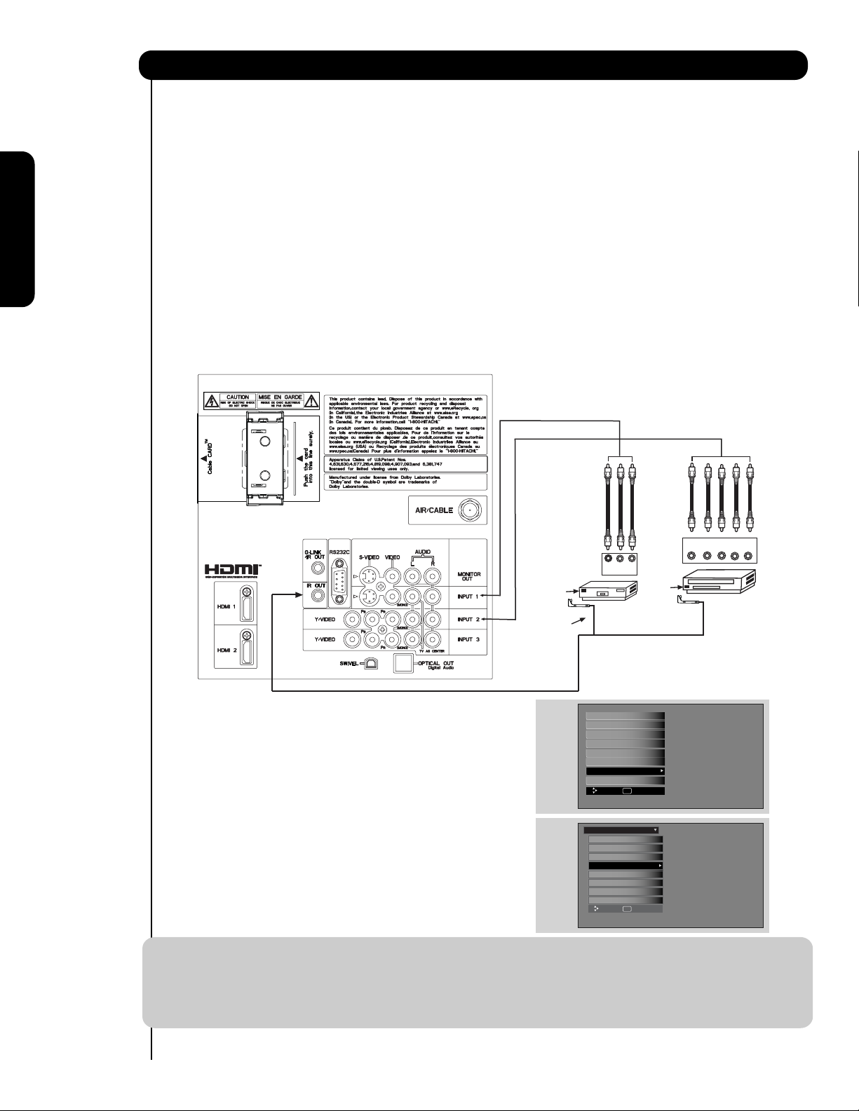
Connecting External Video Sources
Your HITACHI Plasma Television is equipped with an AV Net feature. This feature helps to control your
external Audio/Video equipment (VCR, Set Top Box, DVD, etc.). Once this is setup, it allows your IR Blaster
cable to control your equipment using your HITACHI Plasma TV Remote Control. You can use your
HITACHI remote control to control the Audio/Video equipment command without the equipment’s remote
control.
The Plasma Television Rear Panel has 2 IR Out jacks. Each IR Blaster cable can connect up to 2
external Audio/Video components. Therefore, you can connect the Plasma Television with up to four
components. Please see the following example of an AV Net setup between your Hitachi Plasma
Television and external Audio/Video equipment (VCR and DVD Player).
First time use
1. Connect your external Audio/Video components to the Rear Panel shown below.
2. Connect the IR Blaster cable to the IR OUT terminal of the Rear Panel.
3. Place the IR Blaster in front of the infrared sensor of the external components you wish to control.
OUTPUT
YP
R L
B/CBPR/CR
V L R
OUTPUT
CONNECTING EXTERNAL AUDIO/VIDEO COMPONENTS TO IR OUT FOR AV NET
Infrared
Sensor
IR
Blaster
VCR
Infrared
Sensor
DVD
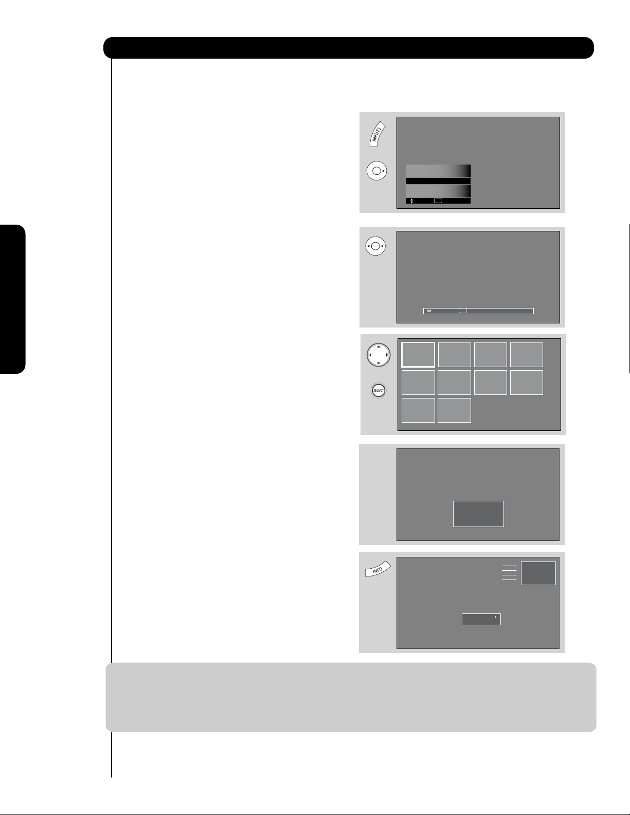
4. ACCESS THE AV NET SETUP WIZARD
Press the MENU button.
5. Use the CURSOR PAD to highlight SETUP.
Video
Audio
TV Guide On Screen
Channel Manager
Locks
Timers
Setup
Power Swivel
Move SEL Select
6. Press the SELECT or CURSOR PAD button to
select.
7. Use the CURSOR PAD to highlight the
SET THE AV NET feature then press the SELECT
button.
Setup
Set the Menu Options
Set The Screen Saver
Set The Inputs
Set The AV NET
Set The Closed Captions
Set The IR Out
Select The Quick Start Option
Reset the Software
SEL
Move
Return
8. Follow the Setup procedure on pages 67-74.
NOTE: 1. The Rear Panel has two IR OUT terminals which can control up to a total of four external components.
2. The IR Blaster must be placed in front of the external components infrared sensor for the AV Net
to work. Double-sided mounting tape may be used to hold the IR Blaster in place.
3. The correct codes must be chosen for each of the Audio/Video components for the AV Net to
function properly.
24
Page 25
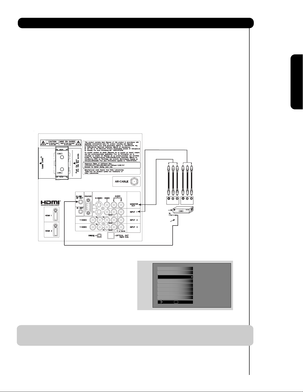
Connecting External Video Sources
Your HITACHI Plasma Television is equipped with a G-LINKTM feature. This connection is necessary for the
TV Guide On Screen
TM
system to enable VCR recording features. Once you setup the G-LINKTM (IR Blaster)
connector, then you can use your HITACHI Plasma TV Remote Control and TV Guide On Screen
system to control your VCR recording features.
TM
The Plasma Television Rear Panel has IR OUT/G-LINK
2 external Audio/Video components. Please see the following example of a G-LINK
terminals. One IR Blaster cable can connect up to
TM
setup between your
HITACHI Plasma Television and external Audio/Video equipment (VCR).
TM
CONNECTING THE VCR TO G-LINK
FOR TV Guide On ScreenTMSYSTEM
1. Connect your external Audio/Video components to the Rear Panel shown below.
2. Connect the IR Blaster cable to the IR OUT/G-LINK
TM
output terminal of the Rear Panel.
3. Place the IR Blaster in front of the infrared sensor of the external components you want to control.
TM
First time use
V L R
4. To access the TV Guide On ScreenTMsystem,
press the MENU button.
5. Use the CURSOR PAD to highlight TV Guide
On Screen
TM
.
6. Press the SELECT or CURSOR PAD button to
select.
V L R
Infrared
Sensor
IR
Blaster
Video
Audio
TV Guide On Screen
Channel Manager
Locks
Timers
Setup
Power Swivel
Move
INPUT
SEL Select
OUTPUT
VCR
7. Follow the Setup procedure on pages 52-54.
NOTE: 1. The IR Blaster must be placed in front of the external components infrared sensor for the G-LINKTM feature to
work.
2. G-LINK
TM
connections are available on both IR OUT terminals.
25
Page 26
The Remote Control
In addition to controlling all the functions on your
HITACHI Plasma TV, the new remote control is
designed to operate different types of VCRs, cable
boxes, set-top-boxes, satellite receivers, DVD players,
and other audio/video equipment with one touch.
Basic operation keys are grouped together in one
area.
To operate your Plasma TV, select TV by
pressing the Source button of the Source Select
on the remote. The TV mode indicator will blink,
indicating that the remote will now control your
television.
To operate your VCR/PVR (Personal Video
Recorder), select PVR/VCR by pressing the Source
button of the Source Select on the remote. The
PVR/VCR mode indicator will blink, indicating that
the remote will now control your VCR/PVR (see
page 39 for instructions on how to program the
remote to control your VCR/PVR).
To operate your cable box, select SAT/CBL by
The Remote Control
pressing the Source button of the Source Select
on the remote. The SAT/CBL mode indicator will
blink, indicating that the remote will now control
your cable box (see page 36 for instructions on
how to program the remote to control your cable
box).
To operate your set-top-box or satellite receiver
select SAT/CBL by pressing the Source button of
the Source Select on the remote. The SAT/CBL
mode indicator will blink, indicating that the remote
will now control your set-top-box or satellite receiver
(see page 37 for instructions on how to program the
remote to control your set-top-box or satellite
receiver).
To operate your DVD player, select DVD by
pressing the Source button of the Source Select
on the remote. The DVD mode indicator will blink,
indicating that the remote will now control your
DVD Player (see page 38 for instructions on how to
program the remote to control your DVD player).
26
Page 27
How to Use the Remote to Control Your TV
쐃
POWER button
Press this button to turn the TV set on or off when
the remote is in TV mode. (See page 26 for instructions
on how to set the remote control to TV mode).
쐃
쐇
1
쐄
쐆
쐎
쐈
쐉
씈
씊
씊
MODE Indicator
쐇
쐋
쐏
Turns on or blinks three times to show remote control
mode.
쐋
SOURCE SELECT button
Press this button to select remote control mode.
9
쐏
PAUSE button
Press the PAUSE button to freeze the picture.
쐂
쐊
Press the EXIT button to return the picture to
motion. Press the PAUSE button repeatedly to
cycle through the three different freeze modes (see
page 35).
The Remote Control
쐅
씋
씉
Freeze
씋
씌
씋
1
8
씋
DAY/NIGHT button
쐄
Press this button to toggle between Day (Normal),
Day (Dynamic) and Night picture mode settings. Select
DAY for day time viewing with more brightness and
contrast to compete with room light. Select NIGHT
for night time viewing with less brightness and
contrast for a more detailed picture (see page 45
for settings changes).
Freeze
Freeze
Freeze
Freeze
NOTE: For automatic DAY/NIGHT picture mode settings,
see page 64.
27
Page 28
How to Use the Remote to Control Your TV
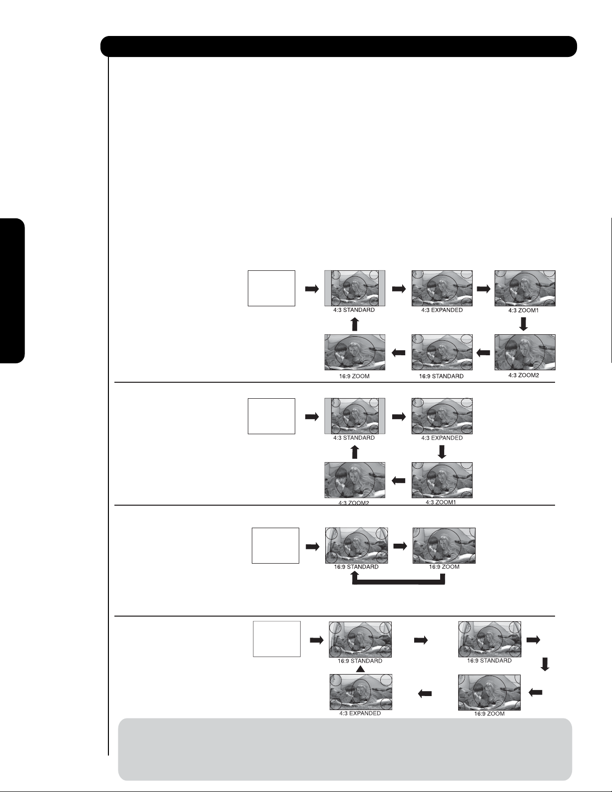
쐂
ASPECT button
Press this button to quickly change the picture format ASPECT ratio. Depending on the input signal format
received, the picture format ratio allows you to adjust the images through the following options.
4:3 STANDARD
Use this aspect mode to display conventional (4:3)
images. Side panels (gray areas) are placed to the
left and right of the image to preserve the original
aspect ratio of the source. Note: Use this mode for
only 15% of your total viewing time to prevent
uneven aging of the phosphors. Phosphors in the
lighted area of the picture will age more rapidly
1
8
than the gray areas.
4:3 EXPANDED
Use this aspect mode to display conventional (4:3)
sources by linearly increasing image expansion
from the center towards the edges of the display
area in order to fill it.
• Antenna-Analog Channel
• S-Video/Video Input
(Auto Aspect: Off)
• HDMI-480i/480p Input
(Auto Aspect: Off)
• Component-480i/480p
Input (Auto Aspect: Off)
IMAGE INPUT
The Remote Control
Note: Please see Appendix A
on page 182-183.
4:3 ZOOM1/ZOOM2
Use these aspect modes to zoom in on conventional
(4:3) sources.
16:9 STANDARD 1
Use this aspect mode to display 16:9 sources like
HDTV and DVD’s preserving the original 16:9
aspect ratio showing 95% of the size.
16:9 STANDARD 2
Use this aspect mode to display 16:9 sources like
HDTV and DVD’s preserving the original 16:9
aspect ratio showing 100% of the size.
16:9 ZOOM
Use this aspect to Zoom-in once while in 16:9 aspect.
1
• Antenna-Digital Channel (4:3)
• S-Video/Video 4:3/Letter
Input (Auto Aspect: On)
• HDMI-480i/480p 4:3/
Letter Input (Auto Aspect: On)
• Component-480i/480p 4:3/
Letter Input
(Auto Aspect: On)
Note: Please see Appendix A
on page 182-183.
• S-Video/Video 16:9 Input
(Auto Aspect: On)
• HDMI-480i/480p 16:9 Input
(Auto Aspect: On)
• Component-480i/480p
16:9 Input
(Auto Aspect: On)
Note: Please see Appendix A
on page 182-183.
• Antenna-Digital Channel (16:9)
• HDMI-720p/1080i/1080p Input
• Component-720p/1080i
Input
IMAGE INPUT
IMAGE INPUT
IMAGE INPUT
1
2
Note: Please see Appendix A
on page 182-183.
NOTE: 1. The Aspect Stylein all video inputs have independent Aspect Style setting.
2. Vertical position adjustments are directly available when you choose 4:3 EXPANDED/ZOOM1/ZOOM2 or
16:9 ZOOM aspect style (see also page 47).
28
3. When displaying 16:9 STANDARD 2 it may appear lines at the edge of the picture this is normal operation
of the TV.
Page 29
How to Use the Remote to Control Your TV
쐆
MENU button
The MENU button will start the On-Screen Display.
쐊
EXIT button
This button will exit all On-Screen Displays.
쐎
INPUTS button
When the remote control is in TV mode, press this
button to access the INPUTS menu. Use the
CURSOR and SELECT buttons to scroll and select
the inputs that are being used. Pressing the
INPUTS button repeatedly will also cycle through
the Inputs menu items. Then press the SELECT
button to select.
HDMI-Front
Photo Input
Air / Cable
Input 1
Input 2
Move SEL Select
INPUT 1 Select to choose INPUT 1.
INPUT 2 Select to choose INPUT 2.
INPUT 3 Select to choose INPUT 3.
INPUT- FRONT Select to choose FRONT INPUT .
HDMI 1 Select to choose HDMI 1 INPUT.
HDMI 2 Select to choose HDMI 2 INPUT.
HDMI- FRONT Select to choose FRONT HDMI INPUT.
PHOTO INPUT Select to access your pictures from a
digital camera, MMC/SD Flash memory
or memory card connected to the Photo
Input in the front panel of the Plasma
TV (see pages 30-31).
AIR/CABLE Select between Air or Cable signal.
쐅
PICTURE-IN-PICTURE button
See separate section on pages 33-34 for a more
detail description.
쐈
CURSOR buttons/SELECT button
All the On-Screen Display features can be set or
adjusted by using the CURSOR buttons and the
SELECT button, except for numeric entries. Press
the CURSOR buttons toward desired direction and
press the SELECT button to select.
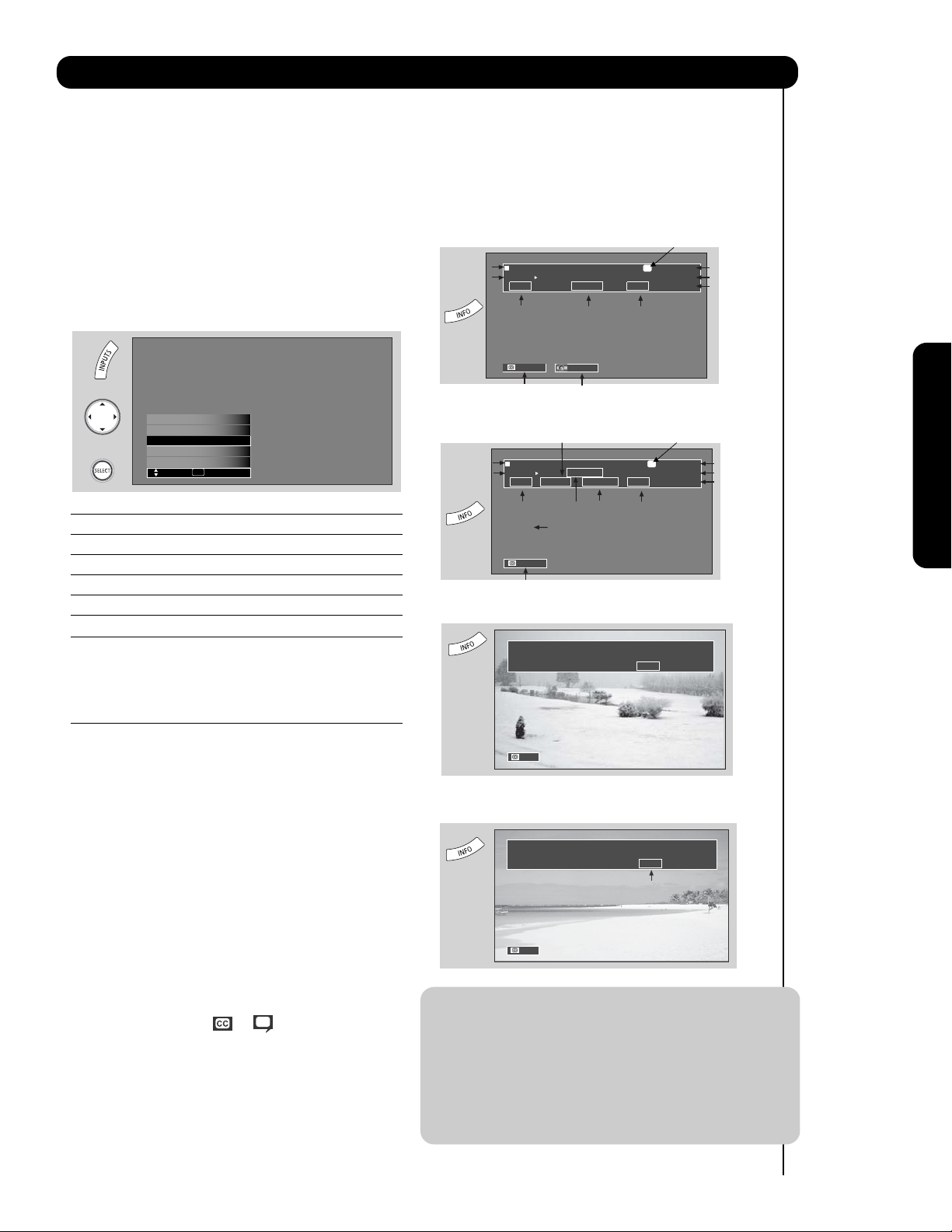
씉
INFO button
Press this button when you want to check the
channel being received, the picture source, if
the channel has stereo (ST) or second audio
program (SAP), the time, CHANNEL ID and if
the TIMER is set.
ANALOG CHANNELS
Program Information
Program Run Time
Program Information
Program Run Time
Show Name Air 8
3:00PM-
3:30PM KXYZ-HD
ST TV-G 480i 3:17PM
Audio
Broadcast
Auto STEREO
Closed
Caption setting
DIGITAL CHANNELS
Show Name Air 15-1
3:00PM-
ST 1080i 3:17PM
Audio
Broadcast
Auto
Closed
Caption setting
Broadcast
Rating
Audio Source
Selection
Digital Closed Caption
This icon will appear only when
receiving a Digital Broadcast with
Closed Captioning.
REGION 5
3:30M KPBS-HD
DTvCC TV-G
Broadcast
Alternate
Rating
Rating
Program Description
(Press INFO again for a more detailed description)
A
Picture Format
Picture Format
When an S-VIDEO Input is connected
to INPUT 1
480i 3:17PM
Auto
When a Component Video: Y-PbPr
Input is connected to INPUT 3
480i 3:17PM
Input Signal
Format
Analog Channel
Digital channel
D
S-IN: 1
Y-PBPR: 3
Main Picture Source
and channel indication
Broadcast channel
identication
Clock
Main Picture Source
and channel indication
Broadcast channel
identication
Clock
The Remote Control
쐉
CLOSED CAPTIONS (CC) button
Use this button to display the dialogue, narration,
and/or sound effects of a television program or home
video which are displayed on the TV screen when
available. Your local TV program guide denotes
these programs as or .
씈
GUIDE button
Press this button to access the TV Guide On Screen
interactive display (see page 52). Press this button
to access the Channel Guide of the (CBL), and
(SAT/STB) while in (CBL)(SAT/STB) mode.
Auto
NOTE: 1. Press the INFO button again or the EXIT
button to return to normal viewing.
2. The Aspect setting will not be shown if
TM
the channel is locked.
3. Program Information, Program Run Time
and Program Description can be displayed
by Guide Listing data even if receiving
analog channels.
29
Page 30
How to Use the Remote to Control Your TV
Please Enter
Picture Number
--
PHOTO INPUT
This feature is useful for viewing digital still pictures from your digital camera, MMC/SD memory cards using the
Photo Input in the front panel of the TV.
1. Press the INPUTS button to cycle through the
INPUTS selections until the PHOTO INPUT is
selected. Press the SELECT button or
CURSOR PAD .
HDMI 1
HDMI-Front
Photo Input
Air / Cable
Input 1
SEL Sel.
Move
2. Press the CURSOR PAD or to access the
next or previous photo.
Next SEL Thumbnail [0-9] Jump
The Remote Control
3. Press the SELECT button to view THUMBNAIL.
4. Use the CURSOR PAD buttons , , or
and the SELECT button to navigate and select
individual chosen photos.
5. Press the picture number to jump from picture
to picture.
No. 02/08
No. 02/08
06/13/05
06/13/05
2048x1536
2048x1536
DSC00467
DSC00467
6. Press the INFO button to access PHOTO Input
Picture No.
Resolution
File Name
Date
menu and to view Photo information.
7. Press the CURSOR PAD or and the
SELECT button to navigate and select the
PHOTO Input menu.
Rotate
Slideshow
NOTES: 1. Contrast will decrease automatically if stationary images such as digital still photos are left
on the screen for more than 3 minutes.
2. The maximum number of digital Photos that can be displayed is 999.
3. Press INFO button to show Picture Numbers in Thumbnail view, plus other information in
individual photos.
4. The screen may show “Input device not detected” if the MMC/SD memory card is not inserted.
30
Page 31

How to Use the Remote to Control Your TV
ROTATE
Select this menu item to rotate selected photos
either clockwise (CURSOR PAD ) and
counterclockwise (CURSOR PAD ).
SLIDESHOW
Select this menu item to start a slideshow of the
digital photos. While the Interval sub menu is
highlighted, press the SELECT button to cycle
through the interval time from 5, 10 and 30 seconds.
Press the SELECT button to stop on a chosen
picture of the slideshow. After 30 seconds, the
slideshow will resume or press the SELECT button
again to continue with the slideshow.
Rotate
Rotate
Slideshow Start
Slideshow Start
Rotate
The Remote Control
Interval 5sec
NOTES: 1. Automatic contrast reduction also applies during SLIDESHOW, then press any button to
continue.
2. Photo file names modified on a computer should be 8 characters (Ex. ABCD1234.jpg). 1st
character: letters; 2nd to 4th: letters or numbers; 5th to 8th: numbers. Photo files should be
first placed on a sub directory name with 8 characters (Ex. 123ABCDE). 1st to 3rd: number;
4th to 8th: letters. The sub directory then should be placed on a main directory with a
“dcim” file name format.
3. Supported image types are up to 3072 x 2304; JPEG format should conform with DCF
Standard (Design rule for Camera File System).
4. This TV set displays only digital pictures from digital cameras which meet DCF Standard.
Pictures that were copied, edited or modified on a computer may not be displayed on the TV
set.
31
Page 32

How to Use the Remote to Control Your TV
씊
VOLUME (VOL), MUTE button
Press the VOLUME button (
the desired sound level.
or ) until you obtain
Press the FAV CH button to switch to Favorite
(FAV) channel mode. You will know you are in
Favorite Channel mode when (FAV) is displayed
and the displayed channel is GREEN. Press it
To reduce the sound to one half of normal volume
(SOFT MUTE) to answer the telephone, etc., press
the MUTE button. Press the MUTE button again to
turn the sound off completely (MUTE). To restore
the sound, press the MUTE button one more time,
or VOL UP (
).
again to return to your regular tuned channels. You
can add any channel to your Favorite channel list
by pressing and holding down the FAV CH button
until the displayed channel turns from WHITE to
highlighted GREEN. You can also delete a channel
from your favorite channel list by pressing and
holding down the FAV CH button until the
displayed channel turns highlighted GREEN to
WHITE.
Cable 6
Volume 8
FAV Cable 6
The Remote Control
Soft Mute 8
Mute 8
Closed Captioning will display automatically when
MUTE/SOFT MUTE is on and Closed Caption is set
to AUTO (see page 75).
When the TV power is turned off at a volume level
31 or greater, the volume level will default to 30
when the TV is turned on. However, if it is set to a
level 30 or less, the volume level will be at the level
it was set when the TV is turned on.
CHANNEL SELECTOR/FAVORITE CHANNEL
씋
(FAV CH)/ENTER buttons
The CHANNEL SELECTOR buttons are used to
select channels, lock access code, etc. Use the
CHANNEL SELECTOR buttons to enter one, two,
or three numbers to select channels. Enter 0 first
for channels 1 to 9, or simply press the single digit
channel you wish to tune then press the ENTER button
for the TV to tune. Channel selection may also be
performed by CHANNEL (CH) UP (
CHANNEL (CH) DOWN (
).
) or
Cable 6
LAST CHANNEL button
1
7
Press this button to toggle between the current and
last channel viewed.
(-) DASH button
1
8
Use the (-) DASH button with the CHANNEL
SELECTOR buttons to enter Digital Channels that
have subchannel numbers indicated by (-) DASH
(example 15-1).
1
9
RECORD button
Press to record programs when the remote is in
PVR/VCR mode.
32
Page 33

Picture-In-Picture (PIP)
Your HITACHI Plasma TV incorporates one Tuner
technology designed for improved viewing enjoyment
This feature allows you to view Digital Channels and
Video inputs on both the main picture and sub picture
simultaneously, with separate control.
Analog channels cannot be viewed in PIP mode.
Please see table in next page for PIP availability.
To select between main picture and PIP sub picture,
use the CURSOR PAD button the remote. The Orange
highlighted channel display will move with every press
of the CURSOR PAD buttons.
The Picture-in-Picture feature is convenient when you
want to watch more than one program at the same
time.You can watch a TV program while viewing other
programs from any of the video inputs.
Use connection at right to view VCR program as a
sub picture while viewing another program as main
picture (CABLE/AIR Digital channel).
A text message will appear if the PIP feature
NOTE:
is used without a Digital Channel as one of the two
sources.
consult the Owners Manual."
햲 PIP button
"This function is not available, please
Press the PIP button and a sub-picture will appear
in one of three different modes (POP, PIP, or
SPLIT), depending on the INPUT signal. To change
the PIP mode, use the PIP button to cycle through
the three different modes.
CH 1
Back of
VCR
Cable or
Air signal
Video
OUTPUT
VCR
The Remote Control
SPLIT MODE PICTURE-IN-PICTURE
Split Mode PIP displays the main picture and sub-
picture evenly on the screen.
SWAP
Main Picture
Sub Picture
POP MODE PICTURE-IN-PICTURE
POP Mode PIP displays the sub-picture outside of
the main picture. Use the CURSOR PAD ( or )
to move the sub-picture. This feature is not
available with a 1080p/1080i/720p signal. Please
refer to the PICTURE-IN-PICTURE modes table in
next page.
Main Picture
Sub Picture
SWAP
햲
NOTE : 1. Press the CURSOR PAD ( or ) to
enable the sub-picture sound.
33
Page 34

Picture-In-Picture (PIP)
PIP MODE PICTURE-IN-PICTURE
Select CABLE/AIR or INPUT 1~3, Front from the INPUTS menu. Select a channel that has a 1080p/1080i/720p signal.
To prevent a pattern burn, occasionally move the sub-picture using the CURSOR PAD.
Main Picture
SWAP
Sub Picture
PIP Specifications Table
PIP Sub Digital (Air or Cable) Component/Composite/S-IN/HDMI
Mode 1080i 720p 480p 480p 480i 480i 1080i/p 720p 480p 480p 480i 480i
POP
The Remote Control
PIP
16x9
PIP
4x3
SPLIT
Yes*1: Auto Aspect OFF
Yes*2: Auto Aspect ON
Main 16x9 16x9 16x9 4x3 16x9 4x3 16x9 16x9 16x9 4x3 16x9 4x3
Digital
(Air or
Cable)
Component
Composite
S-IN
HDMI
Digital
(Air or
Cable)
Component
Composite
S-IN
HDMI
Digital
(Air or
Cable)
Component
Composite
S-IN
HDMI
Digital
(Air or
Cable)
Component
Composite
S-IN
HDMI
1080i 16x9
720p 16x9
480p 16x9
480p 4x3 䋭 䋭 䋭 䋭 䋭 䋭 Yes Yes Yes Yes Yes Yes
480i 16x9
480i 4x3
1080i/p 16x9 䋭 䋭 䋭 䋭 䋭 䋭 䋭 䋭 䋭 䋭 䋭 䋭
720p 16x9
480p 16x9 Yes*1 Yes*1 Yes*1 Yes*1 Yes*1 Yes*1
480p 4x3 Yes Yes Yes Yes Yes Yes
480i 16x9 Yes*1 Yes*1 Yes*1 Yes*1 Yes*1 Yes*1 䋭 䋭 䋭 䋭 䋭 䋭
480i 4x3 Yes Yes Yes Yes Yes Yes
1080i 16x9
720p 16x9 䋭 䋭 䋭 䋭 䋭 䋭 Yes Yes Yes*2 䋭 Yes*2 䋭
480p 16x9
480p 4x3
480i 16x9 䋭 䋭 䋭 䋭 䋭 䋭 Yes Yes Yes*2 䋭 Yes*2 䋭
480i 4x3
1080i/p 16x9 Yes Yes Yes
720p 16x9 Yes Yes Yes
480p 16x9 Yes*2 Yes*2 Yes*2 䋭 Yes*2 䋭 䋭 䋭 䋭 䋭 䋭 䋭
480p 4x3
480i 16x9 Yes*2 Yes*2 Yes*2
480i 4x3
1080i 16x9
720p 16x9
480p 16x9 䋭 䋭 䋭 䋭 䋭 䋭 䋭 䋭 Yes*1 Yes Yes*1 Yes
480p 4x3
480i 16x9
480i 4x3
1080i/p 16x9 䋭 䋭 䋭 Yes 䋭 Yes 䋭 䋭 䋭 䋭 䋭 䋭
720p 16x9
480p 16x9
480p 4x3 䋭 䋭 䋭 䋭 䋭 䋭 䋭 䋭 䋭 䋭 䋭 䋭
480i 16x9
480i 4x3
1080i 16x9 䋭 䋭 䋭 䋭 䋭 䋭 Yes Yes Yes Yes Yes Yes
720p 16x9
480p 16x9
480p 4x3
480i 16x9 䋭 䋭 䋭 䋭 䋭 䋭 Yes Yes Yes Yes Yes Yes
480i 4x3
1080i/p 16x9 Yes Yes Yes Yes Yes Yes
720p 16x9 Yes Yes Yes Yes Yes Yes 䋭 䋭 䋭 䋭 䋭 䋭
480p 16x9 Yes Yes Yes Yes Yes Yes
480p 4x3 Yes Yes Yes Yes Yes Yes
480i 16x9 Yes Yes Yes Yes Yes Yes
480i 4x3 Yes Yes Yes Yes Yes Yes
䋭 䋭 䋭 䋭 䋭 䋭 䋭 䋭 䋭 䋭 䋭 䋭
䋭 䋭 䋭 䋭 䋭 䋭 䋭 䋭 䋭 䋭 䋭 䋭
䋭 䋭 䋭 䋭 䋭 䋭 䋭 䋭 䋭 䋭 䋭 䋭
䋭 䋭 䋭 䋭 䋭 䋭 䋭 䋭 䋭 䋭 䋭 䋭
䋭 䋭 䋭 䋭 䋭 䋭
䋭 䋭 䋭 䋭 䋭 䋭 䋭 䋭 䋭 䋭 䋭 䋭
䋭 䋭 䋭 䋭 䋭 䋭
䋭 䋭 䋭 䋭 䋭 䋭
䋭 䋭 䋭 䋭 䋭 䋭 䋭 䋭 䋭 䋭 䋭 䋭
䋭 䋭 䋭 䋭 䋭 䋭 䋭 䋭 䋭 䋭 䋭 䋭
䋭 䋭 䋭 䋭 䋭 䋭 䋭 䋭 䋭 䋭 䋭 䋭
䋭 䋭 䋭 䋭 䋭 䋭 䋭 䋭 䋭 䋭 䋭 䋭
䋭 䋭 䋭 䋭 䋭 䋭 䋭 䋭
䋭 䋭 䋭 䋭 䋭 䋭 䋭 䋭
䋭 䋭 䋭 䋭 䋭 䋭 䋭 䋭 䋭 䋭 䋭 䋭
䋭 䋭 䋭 䋭 䋭 䋭 䋭 䋭
䋭 䋭 䋭 䋭 䋭 䋭 䋭 䋭 䋭 䋭 䋭 䋭
䋭 䋭 䋭
䋭 䋭 䋭
䋭 䋭 䋭
䋭 䋭 䋭 䋭 䋭 䋭 䋭 䋭 䋭 䋭 䋭 䋭
䋭 䋭 䋭 䋭 䋭 䋭
䋭 䋭 䋭 䋭 䋭 䋭
䋭 䋭 䋭 䋭 䋭 䋭
䋭 䋭 䋭 䋭 䋭 䋭
䋭
䋭
䋭
Yes
Yes*2
Yes*2
Yes
Yes
Yes*2
䋭
䋭
䋭
Yes Yes Yes Yes Yes Yes
䋭 䋭 䋭 䋭 䋭 䋭
䋭 䋭 䋭 䋭 䋭 䋭
䋭 䋭 䋭 䋭 䋭 䋭
Yes Yes Yes*2
Yes Yes Yes*2
䋭 䋭 䋭 䋭 䋭 䋭 䋭
䋭 䋭 䋭 䋭 䋭 䋭 䋭
䋭 䋭 䋭 䋭 䋭 䋭 䋭
Yes*1 Yes Yes*1 Yes
Yes*1 Yes Yes*1 Yes
Yes*1 Yes Yes*1 Yes
Yes
䋭 䋭 䋭 䋭 䋭 䋭
Yes*2
䋭 䋭 䋭 䋭 䋭 䋭
Yes*2
䋭 䋭 䋭 䋭 䋭 䋭
Yes Yes Yes Yes Yes Yes
Yes Yes Yes Yes Yes Yes
Yes Yes Yes Yes Yes Yes
Yes Yes Yes Yes Yes Yes
䋭 䋭 䋭 䋭 䋭 䋭
䋭 䋭 䋭 䋭 䋭 䋭
䋭 䋭 䋭 䋭 䋭 䋭
䋭 䋭 䋭 䋭 䋭 䋭
䋭 䋭 䋭 䋭 䋭 䋭
Yes*2
䋭
Yes*2
䋭
䋭
䋭
34
Page 35

Picture-In-Picture (PIP)
햳 PAUSE button
Press the PAUSE button repeatedly to toggle
between FREEZE modes (Main Freeze, SPLIT and
STROBE). This is convenient when trying to write
down the address for a mail order company,
recording statistics for a sporting event, etc. To
return the picture to motion, press the EXIT button.
Freeze
Freeze
Freeze
햳
The Remote Control
SPLIT FREEZE
Press the PAUSE button to freeze the picture you
are currently viewing (only the right sub-picture will
freeze). Press the EXIT button to return to normal
viewing.
Freeze
Freeze
MAIN FREEZE
Press the PAUSE button to freeze one frame of the
picture you are currently viewing and the frozen
frame will show in the Main Picture. Press the EXIT
button to return to normal viewing. This feature is
useful for freezing a picture frame with addresses.
Hot Springs Clay Mask
C/O John Doe
Run-Spa Retreat
P.O. Box 55512
Any Town, USA 98765
Check or
Money Order Only
1-800-555-1212
Main Picture
STROBE FREEZE
Press the PAUSE button to freeze three frames of
the picture you are currently viewing (only the 3
sub-pictures will freeze). Press the EXIT button to
return to normal viewing. This feature is useful for
viewing a moving picture that has many details, for
example, a close play in a sporting event or a golf
swing.
Sub Picture
NOTE: 1. The default FREEZE mode is the MAIN
freeze followed by the SPLIT freeze and
then the STROBE freeze. The last FREEZE
mode you selected before you pressed the
EXIT button will be the one that comes up
after pressing the PAUSE button again.
2. Each freeze frame in Strobe Freeze is
delayed about 0.1 (1/10) second.
35
Page 36

The Remote Control for Cable Box Functions
OPERATING THE PRECODED
FUNCTION FOR YOUR CABLE BOX.
This remote is designed to operate different types of
cable boxes. You must first program the remote to
match the remote system of your cable box (refer to
pages 41-42 for pre-codes).
햲
햳
1. Turn ON your cable box.
햲
햳
2. To switch to Cable (CBL) pre-coded mode, use the
SOURCE SELECT button on the remote control
to position the LED light to the corresponding
selection SAT/CBL.
햲
햳
햲
햳
햳
3. Hold down the SOURCE SELECT button on the
remote and enter the four digit preset code that
matches your cable box as shown on pages 41-42.
Release the SOURCE SELECT button. The indicator
light will flash 3 times if the code was accepted.
4. Aim the remote at the cable box and press the
POWER button. The remote will turn off your cable
The Remote Control
box when the correct four digit preset code is
entered. When this occurs, the remote control is
programmed for your cable box. If the cable box
does not turn off, try a different four digit preset
code.
햲
햳
햲
햲
햲
5. The remote will now control your Cable box.
NOTE: 1. If your cable box cannot be operated after
performing the above procedures, your
cable box code has not been precoded
into the remote.
2. In the unlikely event that your cable box
cannot be operated after performing the
above procedures, please consult your
cable box operating guide.
3. The remote control will remember the
codes you have programmed until the
batteries are removed from the
remote control. After replacing the
batteries repeat the entire programming
procedure as stated above.
햲 PRECODED CABLE BOX buttons
These buttons transmit the chosen precoded cable
codes :
-Power
-Menu
-Exit
-Guide
햳 EXCLUSIVE TV buttons
These buttons are for operating the TV :
-Day/Night
-Aspect
-PIP
-Pause
MY CABLE BOX CODE IS:
-Cursor & Select
-Info
-Channel Up & Down
-Last CH
-CC
-Vol Up & Down
-Mute
-Number PAD
-Enter
-Inputs (only if
programmed, refer
to page 40)
36
NOTE: Refer to instruction manual of the Cable Box
for operation of the buttons exclusively for
the Cable Box.
Page 37

The Remote Control for Set-Top-Box/Satellite Receiver
OPERATING THE PRECODED FUNCTION FOR
YOUR SET-TOP-BOX/SATELLITE RECEIVER.
This remote is designed to operate different types of
set-top-box/satellite systems. You must first program
the remote to match the remote system of your set-
top-box/satellite systems (refer to pages 41-42 for pre-
codes).
햲
Functions
햳
햳
1. Turn ON your set-top-box/satellite systems.
2. To switch to set-top-box/satellite (SAT) pre-coded
mode, use the SOURCE SELECT button on the
remote control to position the LED light to the
corresponding selection SAT/CBL.
3. Hold down the SOURCE SELECT button on the
remote and enter the four digit preset code that matches
your set- top-box/satellite receiver as shown on page
41-42. Release the SOURCE SELECT button. The
indicator light will flash 3 times if the code was accepted.
4. Aim the remote at the set-top-box/satellite receiver
and press the POWER button. The remote will turn
off your set-top-box/satellite receiver when the
correct four digit preset code is entered. When this
occurs, the remote control is programmed for your
set-top-box/satellite receiver. If the set-topbox/satellite receiver does not turn off, try a
different four digit preset code.
5. The remote will now control your set-top-box/
satellite receiver.
NOTE: 1. If your set-top-box/satellite receiver
cannot be operated after performing the
above procedures, your set-top-box/
satellite receiver code has not been
precoded into the remote.
2. In the unlikely event that your set-topbox/satellite receiver cannot be operated
after performing the above procedures,
please consult your set-top-box/satellite
receiver operating guide.
3. The remote control will remember the
codes you have programmed until the
batteries are removed from the
remote control. After replacing the
batteries repeat the entire programming
procedure as stated above.
햲
햳
햲
햳
햲
햳
햲 PRECODED SET-TOP-BOX/SATELLITE
RECEIVER buttons
These buttons transmit the chosen pre-coded
set-top-box/satellite codes :
-Power
-Menu
-Exit
-Guide
햳 EXCLUSIVE TV buttons
These buttons are for operating the TV :
-Day/Night
-Aspect
-PIP
MY Satellite RECEIVER/
SET-TOP-BOX CODE IS:
-Cursor & Select
-Info
-Channel Up & Down
-Last CH
-CC
-Vol Up & Down
-Pause
-Number PAD
-Enter, Dash
-Mute
-Inputs (Only if
programmed, refer
to page 40).
햲
햳
The Remote Control
햲
햲
햲
NOTE: Refer to instruction manual of the Set-Top-
Box/Satellite Receiver for operation of the
buttons exclusively for the Set-TopBox/Satellite Receiver.
37
Page 38

The Remote Control for DVD Functions
OPERATING THE PRECODED
FUNCTION FOR YOUR DVD PLAYER.
This remote is designed to operate different types of
DVD players. You must first program the remote to
match the remote system of your DVD player (refer to
pages 41-42 for pre-codes).
햲
햲
햳
1. Turn ON your DVD player.
2. To switch to DVD pre-coded mode, use the
SOURCE SELECT button on the remote control to
position the LED light to the corresponding selection
DVD.
3. Hold down the SOURCE SELECT button on the
remote and enter the four digit preset code that
matches your DVD player, as shown on pages 41-42.
Release the SOURCE SELECT button. The indicator
light will flash 3 times if the code was accepted.
4. Aim the remote at the DVD player and press the
POWER button. The remote will turn off your DVD
The Remote Control
player when the correct four digit preset code is
entered. When this occurs, the remote control is
programmed for your DVD player. If the DVD
player does not turn off, try a different four digit
preset code.
햲
햳
햲
햳
햳
햳
햳
햲
햲
5. The remote will now control your DVD player.
NOTE: 1. If your DVD player cannot be operated
after performing the above procedures,
your DVD player code has not been
precoded into the remote.
2. In the unlikely event that your DVD player
cannot be operated after performing the
above procedures, please consult your
DVD player operating guide.
3. The remote control will remember the
codes you have programmed until the
batteries are removed from the
remote control. After replacing the
batteries repeat the entire programming
procedure as stated above.
햲 PRECODED DVD Buttons
These buttons transmit the chosen precoded
DVD codes :
-Power
-Menu
-Info
-Cursor & Select
햳 EXCLUSIVE TV Buttons
These buttons are for operating the TV :
-Day/Night
-Aspect
-PIP
-Exit
MY DVD PLAYER CODE IS:
-Number PAD
-Play, Stop, Pause,
RWD, FWD, Skip RWD,
Skip FWD.
-CC
-Vol Up & Down
-Mute
-Inputs (Only if
programmed, refer
to page 40)
38
NOTE: Refer to instruction manual of the DVD Player
for operation of the buttons exclusively for
the DVD Player.
Page 39

The Remote for VCR/PVR Functions
OPERATING THE PRECODED FUNCTION FOR
YOUR VCR/PVR (Personal Video Recorder).
This remote is designed to operate different types of
VCRs/PVRs. You must first program the remote to
match the remote system of your VCR/PVR (refer to
pages 41-42 for pre-codes).
1. Turn ON your VCR/PVR.
2. To switch to VCR/PVR pre-coded mode, use the
SOURCE SELECT button on the remote control to
position the LED light to the corresponding
selection PVR/VCR.
3. Hold down the SOURCE SELECT button on the
remote and enter the four digit preset code that
matches your VCR/PVR, as shown on pages 41-42.
Release the SOURCE SELECT button. The indicator
light will flash 3 times if the code was accepted.
4. Aim the remote at the VCR/PVR and press the
POWER button. The remote will turn off your PVR
when the correct four digit preset code is entered.
When this occurs, the remote control is
programmed for your VCR/PVR. If the VCR/PVR
does not turn off, try a different four digit preset
code.
5. The remote will now control your VCR/PVR.
햲
햳
햲
햳
햲
햳
햲
햳
햲
햲
햳
The Remote Control
햲
햲
햲
NOTE: 1. If your VCR/PVR cannot be operated after
performing the above procedures, your
VCR/PVR code has not been precoded
into the remote.
2. In the unlikely event that your VCR/PVR
cannot be operated after performing the
above procedures, please consult your
VCR/PVR operating guide.
3. The remote control will remember the
codes you have programmed until the
batteries are removed from the
remote control. After replacing the
batteries repeat the entire programming
procedure as stated above.
햲 PRECODED VCR/PVR Buttons
These buttons transmit the chosen precoded
VCR/PVR codes :
-Power
-Menu
-Exit
-Info
-Record -RWD
햳 EXCLUSIVE TV Buttons
These buttons are for operating the TV :
-Day/Night
-Aspect
-PIP
MY VCR/PVR CODE IS:
-Cursor & Select
-Channel Up & Down
-Number PAD
-Last CH
-CC
-Vol Up & Down
-Mute
-Enter
-Dash (-)
-Play,Pause,Stop
-FWD,Skip FWD
-Inputs (only if
programmed,
refer to page 40)
NOTE: Refer to instruction manual of the VCR/PVR
for operation of the buttons exclusively for
the VCR/PVR.
39
Page 40

How to Use the SOURCE SELECT Button
INPUT ACCESS
This optional feature allows the user of the remote
control to setup it’s SOURCE SELECT button to access
the specified input of the TV. Setup for this feature is
applicable to the remote control’s normal mode only and
only applies to the DVD, PVR/VCR and SAT/CBL
modes.
1. Select the desired device mode (DVD, PVR/VCR,
SAT/CBL) by using your SOURCE SELECT button
to position the LED indicator to the corresponding
selection.
2. Hold down the SOURCE SELECT button on the
remote and enter the four digit preset code that
matches your device as shown on pages 41-42.
3. Then enter the assigned input number (1-7) that the
device is related to (refer below to Table 1).
4. Release the SOURCE SELECT button.
, ,
, ,
5. If done correctly, the device LED indicator will blink
3 times to confirm proper setup.
The Remote Control
6. The remote will now control the desired device.
7. Pressing the INPUTS button will now access the
video input of the desired device.
SETUP EXAMPLE (Hitachi DVD with precode
0573 connected to INPUT 1 of the TV)
Select DVD mode by using your SOURCE SELECT
button to position the LED indicator to DVD.
Hold down the SOURCE SELECT button and
press the numbers 0, 5, 7 and 3.
Then press the number 1 for the assigned input
number of the DVD player.
Table 1
INPUT
INPUT 1 1
INPUT 2 2
INPUT 3 3
INPUT- FRONT 4
HDMI 1 5
HDMI 2 6
HDMI- FRONT 7
ASSIGNMENT NUMBER
Release SOURCE SELECT button.
NOTE: 1. This feature is optional
If done correctly, the device LED indicator will blink
3 times to confirm proper setup.
2. Assigned input numbers can be used more
than once if applicable.
The remote will now control the DVD player.
Press the INPUTS button to instantly access the
video input of your DVD on Input 1.
40
Page 41

Remote Control Codes
A
A
A
A
r
A
Cable BRAND Codes General Instrument ........0869 Daewoo ......................... 0045, 0278, 0020,0561 1479
BC ........................ 0003,0008, 0011 GOI.................................0775, 1775 1278 Panasonic ..................... 1062,0035,0162, 0225,
mericast ................ 0899 Goodmans .....................1246 Daytron ......................... 0020 0616,1035, 1162,1262
mino ......................1602 Hisense ..........................1535 Dell ................................ 1972 Penney .......................... 0035,0037,0240, 0042,
Bell South ............... 0899 Hitachi ........................... 0819,1250 Denon ........................... 0042 0038,1035,1237
Clearmaster ............ 0883 HTS ............................... 0775,1775 DirecTV ......................... 0739 Pentax ........................... 0042,0065,0105
ClearMax ................ 0883 Hughes Network System 1142,0749, 1749,1442 Durabrand ..................... 0039,0038 Philco ............................ 0035,0479
Coolmax ................. 0883 iLo...................................1535 Dynatech ....................... 0000 Philips ........................... 0035, 0081,0062,0618,
Digeo ...................... 1187 JVC.................................0775,1775 Electrohome .................. 0037 0739,1081, 1181
Director ................... 0476 LG ..................................1226,1414 Electrophonic ................ 0037 Pilot ............................... 0037
General Instrument.. 0476,0810,0276,0003, Magnavox ...................... 0724,0722 Emerex ..........................0032 Pioneer ......................... 0067
GoldStar...................0144 Mitsubishi ...................... 0749 0043,0209, 0002,0278, Portland .........................0020
Hamlin .....................0009, 0273 Motorola ........................ 0869 0061, 0208,0479,0561, Presidian ........................1593
Hitachi ..................... 0011,1421 NEC ............................... 1270 0593,1278, 1479,1593, Profitronic ...................... 0240
i3 Micro ....................1602 Next Level ..................... 0869 Fisher ............................ 0047,0104 Proscan .........................0060, 0202,0760,0761
Jerrold ..................... 0476,0810,0276, 0003 Pace ..............................0887 Fuji ................................ 0035,0033 1060
Memorex ................. 0000 Paysat ........................... 0724 Garrard ......................... 0000 Pulsar ............................ 0039
Motorola .................. 1376,0476,0810, 0276 Philips ............................1142,0749, 1749,0724, Gateway ........................ 1972 Quarter .......................... 0046
Multitech ..................0883 Proscan ......................... 0392,0566 0202, 0760,0761,0807, Quasar .......................... 0035,0162, 1035,1162
MultiVision ...............0012 Proton ............................1535 1035, 1060 RadioShack .................. 0000, 1037
Myrio ........................1602 RadioShack ................... 0869 Go Video ....................... 0432,0526 Radix ............................. 0037
Pace ........................1877, 0237,0008 RCA ...............................0566,0855, 0143,1392 GoldStar ........................ 0037,0038,1237 Randex ..........................0037
Panasonic ............... 0000,0107 Samsung ....................... 1377,1276,1108, 1109, Gradiente ...................... 0000 RCA ...............................0060, 0240,0042,0149,
Paragon ...................0000 1442,1609 Harley Davidson ............0000 0065,0105, 0106,0202,
Philips ......................1305,0317 Sanyo ............................1219 Harman/Kardon .............0081, 0038 0760,0761,0807, 0880,
Pioneer ....................1877,0877, 0144,0533 SKY ............................... 0856 Harwood ........................ 0072 1035,1060
Pulsar.......................0000 Sony .............................. 0639,1639,1640 Headquarter .................. 0046 Realistic .........................0035, 0037,0048,0047,
Quasar..................... 0000 Star Choice ................... 0869 Hewlett Packard............. 1972 0000,0104, 0046,0062
RadioShack .............0883 Tivo ............................... 1142,1442 HI-Q ...............................0047 ReplayTV ...................... 0614,0616
RCA .........................1256 Toshiba ......................... 0749,1749, 0790,1285 Hitachi ........................... 0000,0042,0041,0065, Ricavision ......................1972
Regal .......................0279,0273 UltimateTV .................... 1392,1640 0089,0105, 0543,0544 Runco ............................0039
Rembrandt .............. 0011 Uniden ........................... 0724,0722 Howard Computers ....... 1972 Samsung ....................... 0240,0045,0739, 1014
Runco ..................... 0000 US Digital .......................1535 HP ................................. 1972 Sanky ............................ 0048,0039
Samsung .................0144 USDTV ...........................1535 Hughes Network System.0042, 0739 Sansui ........................... 0000,0067,0209,0041,
Scientific Atlanta ......1877,0877,0477, 0008 Voom .............................0869 Humax .......................... 0739 0271,0479, 1479
Sejin ........................ 1602 Zenith ............................ 0856,1856 Hush .............................. 1972 Sanyo ............................ 0047,0240,0104,0046,
Signature................. 0011 iBUYPOWER .................1972 0159
Sony ........................1006 DBS/PVR Codes Jensen .......................... 0041 Scott .............................. 0184,0045,0121, 0043
Starcom .................. 0003 Combo BRAND JVC ............................... 0067,0041,0008 Sears .............................0035,0037,0047,0000,
Supercable ..............0276 DirecTV ..........................1377,0392,0639,1142, KEC ...............................0037,0278 0042,0104, 0046,0105,
Supermax ................0883 1076, 0099,1392,1442, Kenwood ....................... 0067,0041, 0038 1237
Thomson ................. 1256 1640 KLH ............................... 0072 Sharp .............................0048,0062, 0807,0848
Tocom ..................... 0012 Dish Network System ....1505, 0775 Kodak ............................ 0035,0037 Shintom ......................... 0072
Torx .........................0003 Dishpro ..........................1505, 0775 LG ................................. 1037 Shogun .......................... 0240
Toshiba ................... 0000 Echostar ........................ 1505,0775 Linksys .......................... 1972 Singer ............................ 0072
Tristar ......................0883 Expressvu ..................... 0775 Lloyd's ........................... 0000,0208 Sonic Blue .....................0614, 0616
V2 ............................0883 Hughes Network System..1142,1442 Logik ............................. 0072 Sony .............................. 0035,0032,0033, 0000,
Viewmaster ............. 0883 Motorola ........................ 0869 LXI ................................ 0037 0636, 1032,1232,1972
Vision ...................... 0883 Philips ............................ 1142,1442 Magnasonic .................. 0593,1278 Stack ............................. 0009,1972
Vortex View .............0883 Proscan ......................... 0392 Magnavox ..................... 0035, 0039,0081,0000, STS ............................... 0042
Zenith ...................... 0000,0525,0899 RCA ...............................1392 0149, 0563,0593,1593, Sylvania .........................0035, 0081,0000,0043,
Cable/PVR Codes
Combo BRAND
mericast ................ 0899
Digeo ....................... 1187
General Instrument ..0810
Jerrold ..................... 0810
Motorola .................. 1376,0810,1187,1106
Pace ........................ 1877,0237
Pioneer .................... 1877,0877
RCA ......................... 1256
Scientific Atlanta ...... 1877,0877
Sony ........................ 1006
Supercable .............. 0276
Thomson ................. 1256
Zenith ...................... 0899
SATELLITE BRAND Codes Bell & Howell ................. 0104 Mitsubishi ...................... 0067,0043,0061, 0807 Vector Research ............0038
(Set Top Box) Broksonic ...................... 0184,0121,0209, 0002 Motorola ........................ 0035,0048 Video Concepts .............0045,0061
lphaStar ................. 0772 0479,1479 MTC .............................. 0240,0000 Videomagic ....................0037
Chaparral ................. 0216 Calix .............................. 0037 Multitech ....................... 0000,0072 Videosonic .................... 0240
Crossdigital .............. 1109 Canon ........................... 0035 NEC .............................. 0104, 0067,0041,0038 Viewsonic ...................... 1972
DirecTV .................... 1377,0392,0566,0639, Capehart ....................... 0020 Nikko ............................ 0037 Villain .............................0000
Dish Network System1505, 1005,0775,1775 0271 Optimus ........................ 1062, 0162,0037,0048, XR-1000 ........................ 0035,0000,0072
Dishpro 1505,1005, 0775,1775 Curtis Mathes ................ 0060,0035,0162, 0041 0104,0432, 0593,1048, Yamaha .........................0038
Echostar 1505,1005, 0775,1775 0760, 1035 1162,1262 Zenith ............................ 0039,0033,0000, 0209,
Expressvu 0775, 1775 Cybernex .......................0240 Optonica ....................... 0062 0479,1139, 1479
GE 0566 CyberPower .................. 1972 Orion ............................. 0184,0209, 0002,0479 ZT Group .......................1972
0011
0012,0011
1187,1254, 1106 1076,0722, 0099,1442
1639,1142, 0247,0749,
1749,0724, 0819,1856,
1076,1108, 0099,1109,
1414,1442, 1609,1392,
1640
Memorex ....................... 0724 Emerson ........................0037,0184,0000,0121, Polk Audio ..................... 0081
Panasonic ..................... 0247,0701 Funai ............................. 0000,0593,1593 Protec ............................0072
Samsung ....................... 1442 1781 0593,1593, 1781
Sony ..............................
Star Choice ...................
VCR BRAND Codes Matsushita .................... 0035,0162, 1162 Tatung ........................... 0041
ABS ............................... 1972 Media Center PC .......... 1972 Teac .............................. 0000,0041
Admiral .......................... 0048,0209 MEI ............................... 0035 Technics ........................0035, 0162
Adventura ..................... 0000 Memorex ...................... 0035,0162, 0037,0048, Teknika ..........................0035,0037, 0000
Aiko ............................... 0278 0039,0047, 0240,0000, Thomas ......................... 0000
Aiwa .............................. 0037,0000,0124, 0307 0104,0209, 0046,0307, Tivo ............................... 0618,0636,0739, 1996
Akai ............................... 0041,0061,0106,0175 0479,1037, 1162,1237 TMK .............................. 0240,0208
Alienware ...................... 1972 1262 Toshiba ......................... 0045,0043, 0845,1008,
America Action .............. 0278 MGA ............................. 0240, 0043,0061 1145, 1972,1996
American High .............. 0035 MGN Technology ......... 0240 Totevision ...................... 0037,0240
Asha .............................. 0240 Microsoft ...................... 1972 Touch .............................1972
Audiovox ....................... 0037,0278 Mind ............................. 1972 Unitech .......................... 0240
Beaumark ..................... 0240 Minolta .......................... 0042, 0105 Vecto
Carver ........................... 0081 Niveus Media ................ 1972 Voodoo .......................... 1972
CCE .............................. 0072,0278 Noblex .......................... 0240 Wards ............................0060, 0035,0048,0047,
Citizen ........................... 0037,0278,1278 Northgate ...................... 1972 0081, 0240,0000,0042,
Colt ............................... 0072 Olympus ....................... 0035 0072,0149, 0062,0760
Craig ............................. 0037,0047, 0240,0072 Onkyo ........................... 0222 White Westinghouse ..... 0209,0072
0639,1640 Magnin .......................... 0240 Symphonic .................... 0000,0593, 1593
0869 Marantz ......................... 0035,0081 Systemax ...................... 1972
GE ................................. 0060,0035,0240,0065, Quartz ........................... 0046
Marta ............................. 0037 Tagar Systems .............. 1972
0045
The Remote Control
41
Page 42

Remote Control Codes
DBS/PVR Codes Enterprise 0591 Sony 0533,1533,0864,1033,
Combo BRAND ESA 0821,1268 1431
Hughes Network Systems 0739 Fisher 0670,1919 Sova 1122
Philips 0739 Funai 0675,1268,1334 Sungale 1074
Samsung 0739 Gateway 1073,1077,1158 Superscan 0821
PVR BRAND Codes Go Video 0744,0715,0741,0783, Sylvania 0675,0821,1268
ABS 1972 0833,0869,1044,1075, Symphonic 0675,0821
Alienware 1972 1099,1144,1158,1304, Teac 0758,0790,0809
CyberPower 1972 1730 Technics 0490,0703
Dell 1972 Go Vision 1071,1072 Technosonic 0730
DirecTV 0739 GoldStar 0741 Techwood 0692
Gateway 1972 GPX 0699,0769 Terapin 1031
Hewlett Packard 1972 Greenhill 0717 Theta Digital 0571
Howard Computers 1972 Harman/Kardon 0582,0702 Toshiba 0503,0695,1045,1154
HP 1972 Hitachi 0573,0664,1247,1919 Tredex 0799,0800,0803,0804
Hughes Network Systems 0739
Humax 0739 iLo 1348 Urban Concepts 0503
Hush 1972 Initial 0717 US Logic 0839
iBUYPOWER 1972 Insignia 1268 Venturer 0790
Linksys 1972 Integra 0627 Vizio 1064,1226
Media Center PC 1972 JBL 0702 Xbox 0522
Microsoft 1972 Jensen 1016 Yamaha 0490,0539,0545
Mind 1972 JSI 1423 Zenith 0503,0591,0741,0869
Niveus Media 1972 JVC 0558,0623,0867,1164 Zoece 1265
Northgate 1972 jWin 1049,1051
Panasonic 0616 Kawasaki 0790 DVD-R Codes
Philips 0618,0739 Kenwood 0490,0534,0682,0737 Accurian 1416
RCA 0880 KLH 0717,0790,1020,1149 Apex Digital 1056
ReplayTV 0614,0616 1261 Aspire Digital 1168
Samsung 0739 Konka 0711,0719,0720,0721 Coby 1086
Sonic Blue 0614,0616 Koss 0651,0896,1423 CyberHome 1129
Sony 0636 ,1972 Landel 0826 Funai 0675,1334
Stack 0009,1972 Lasonic 0798,1173 Gateway 1073,1158
Systemax 1972 Lenoxx 1127 Go Video 0741,1158,1304,1730
The Remote Control
Tagar Systems 1972 LG 0591,0741,0801,0869 iLo 1348
Tivo 0618,0636,0739 LiteOn 1058,1158,1416,1440 JVC 1164
Toshiba 1008,1972,1996 Loewe 0511 LG 0741
Touch 1972 Magnavox 0503,0539,0646,0675, LiteOn 1158,1416,1440
Viewsonic 1972 0821,1268 Magnavox 0646,0675
Voodoo 1972 Malata 0782,1159 Panasonic 0490
ZT Group 1972 Marantz 0539 Philips 0646
DVD BRAND Codes Mintek 0839,0717 RCA 0522
Accurian 1072 ,1416 Momitsu 1082 Sensory Science 1158
Advent 1016 NAD 0741 Sharp 0675
Aiwa 0641
Akai 0695 ,0770,0899, Nesa 0717 Sylvania 0675
Alco 0790 Next Base 0826 Zenith 0741
Allegro 0869 NexxTech 1402
Amphion Media Works 0872 Norcent 1003,0872,1107,1265
AMW 0872
Apex Digital 0672,0717,0755,
Arrgo 1023 Philco 0690,0733,0790,0862,
Aspire Digital 1168,1407 1855,2000
Audiologic 0736,
Audiovox 0790,1041,1071, 0854,1260,1267,1354
Axion 1071,1072 Polaroid 1020,1061,1086
B & K 0655,0662 Polk Audio 0539
Blaupunkt 0717 Portland 0770
Blue Parade 0571 Presidian 0675,1072
Broksonic 0695,0868 Prima 1016
Cambridge Soundworks 0690 Proscan 0522
Cinea 0831 ProVision 0778
CineVision 0876,0833,0869 Qwestar 0651
Citizen 1277 RCA 0522,0571,0717,0790,
Coby 0778,0852,1086,1107 0822,1022,1132,1193
Craig 0831 Rotel 0623
Curtis Mathes 1087 Rowa 0823
CyberHome 0816,0874,1023,1024 Sampo 0698,0752
Daewoo 0784,0705,0833,
Denon 0490,0634 Sanyo 0670,0695,0873,1919
Desay 1407 Sensory Science 1158
Disney 0675,1270 Sharp 0630,0675,0752,1256
Dual 1068,1085 Sharper Image 1117
Durabrand 1127 Sherwood 0633,0770,1043,1077
DVD2000 0521 Shinsonic 0533,0839
Emerson 0591,0675,0821,1268 Sonic Blue 0869,1099
0795,0796,0797
1004,1020,1056
1100 1462,1490,1762
1121,1122
1165,1177,1351
1117,1129,
1169,1172,1234,
42
GE 0522,0815,0717 SVA 0860,1105
Hiteker 0672 TYT 0705
Memorex 0695,0831,1270 Pioneer 0631
Microsoft 0522 Polaroid 1086
Mitsubishi 1521,0521 Samsung 0490
NEC 0785 Sony 1033,1431
1089
Onkyo 0503,0627,0792
OptoMedia Electronics 0896
0794
Oritron 0651
,0830
Panasonic 0490,0632,0703,1362,
,1061
Philips 0503,0539,0646,0675,
1072
Pioneer 0525,0571,0631,0632
Rio 0869
Samsung 0490,0573,0820,0899,
0869
Sansui 0695
1242
1044,1075
Page 43

On-Screen Display
Auto Movie Mode Select the Original 3:2 Pulldown
detection or Smooth Motion feature.
1. Press MENU on the remote control to display the
different features on your HITACHI Plasma TV.
2. Use the CURSOR PAD (buttons ,, and )
and highlight a different feature of the On-Screen
Display menu. Press the SELECT button to select.
3. Press EXIT on the remote control to quickly exit
from a menu.
This part of the screen shows
which selections are available.
Video
Audio
TV Guide On Screen
Channel Manager
Locks
Timers
Setup
Power Swivel
Move
SEL
Select
This part of the screen
shows which Remote
Control buttons to use.
NOTE: The On Screen Display (OSD) for the different submenus shown in next pages are for illustration
purposes only, therefore; doesn't reflect the actual apearance of the OSD of your HITACHI Plasma TV.
Video
Picture Mode Select between 3 pictures modes;
Contrast Adjust contrast.
Brightness Adjust brightness.
Color Adjust color.
Tint Adjust tint.
Sharpness Adjust sharpness.
ColorTemperature Set this to High for less intense
Black Enhancement Enhances shadow detail in dark
Contrast Mode Use this function to choose
Noise Reduction Reduces conspicuous noise in
Cross Color NR
MPEG NR Reduces mosquito noise in
Day Dynamic, Day Normal and Night.
Game Mode Set the Game mode Off/On while
Color Space Choose WIDE to select
color with more blue, set to Medium
Auto Color The AUTO COLOR function
for natural color, set to Standard for
standard colors or Black and White
for more reddish color.
scenes.
between two Contrast Mode
settings.
the picture.
Reduces cross color noise in
the picture.
Black Side Panel Set the gray side bars On/Off
Aspect Choose the picture format
Reset Video Settings Choose to Reset Video Settings
the picture.
playing videogames in TV set.
Hi-Fidelity color mode or
STANDARD for Faithful color
mode with HDTV standard.
automatically monitors and
adjusts the color to maintain
constant color levels even after
a program or channel changes.
It also maintains natural flesh
tones while preserving fidelity
of background colors.
when watching 4:3 signals in
standard mode.
aspect ratio.
to factory settings and to see the
Smooth Motion Feature Demo.
On-Screen Display
43
Page 44

On-Screen Display
Unlocked Power Swivel enabled. Control
the motorized Table Top Stand.
Locked Power Swivel disabled.
Power Swivel
2. Power Swivel feature is only available when
Table Top Stand is connected.
and to Reset TV settings.
TV Guide On Screen Set, Control and navigate the
system
Audio
Treble Adjust the treble.
Bass Adjust the bass.
Balance Adjust the balance.
Surround Select Surround settings (Off,
Wide, Normal)
Bass Boost Select Bass Boost option ON or OFF.
Audio Source Select between three Audio
Sources.
Internal Speakers Select internal or external
speakers.
Auto Noise Cancel Eliminates the noise between
stations.
Perfect Volume Adjust volume in fixed setting
between stations.
Loudness Adjust Loudness.
Language Select Language options if
available.
Digital Output Select Optical Output options.
DRC Select Dynamic Range
Compression to ON or OFF.
Lip Sync Synchronizes audio with video signal
on digital and analog sources.
NOTE: The Language, Digital Output, and the
Dynamic Range Compression feature of the
Audio OSD are only available for Digital
channels.
Region 5 Ratings system for DTV Signal
to block various types of
programs.
Timers
Set the Clock Set Clock Settings.
Set Sleep Timer Set Sleep Timer intervals
(30 min. intervals, 00:30-3:00).
Set Day/Night Timer Set Day/Night picture mode
settings.
Setup
Set The Menu Options Choose English, French, or
Spanish text and Background.
Set The Screen Saver Select Screen Saver options
to prevent screen burn.
Set The Inputs
Set The AV Net Set AV NET Wizard.
Set The Closed Captions Feature to display dialogue/text.
Set The IR Out Set IR Out source.
CableCARD Information Access important CableCARD
Select The Quick Select the TV Quick Start Up
Start Option Option.
Reset The Software Select to upgrade TV software
Label Video Inputs, VCR, DVD,
etc.
and Diagnostics info.
TV Guide on Screen
Channel Manager
On-Screen Display
Signal Meter Access Signal Meter.
Auto Channel Scan Set Auto Channel Scan.
Channel List Set Channel List.
Locks
Change Access Code Change Lock access code.
Engage Lock Choose to lock channel,
Movie Ratings Block various types of movies
TV Ratings Block various types of movies
Canadian Ratings (ENG)
Canadian Ratings (FRN)
44
and/or Front panel.
and video types based on
motion picture ratings.
and television programming
based on a parental guide
ratings.
Block various types of movies
and television programming
based on the Canadian ratings
system.
Block various types of movies
and television programming
based on the Canadian French
ratings system.
NOTE: 1. The Signal Meter feature of the Channel
Manager OSD is only available for Digital
channels.
Page 45

Video
Video
Select VIDEO to adjust picture settings and improve
picture quality. You can independently customize each of
the Video Inputs to your preference to increase viewing
performance and pleasure depending upon the video
program being viewed. If RESET is selected, only the
selected input will reset to initial conditions.
Picture Mode
Use this function to choose from automatic picture
settings to optimize your TV’s performance.
1. Use the CURSOR buttons
select PICTURE MODE settings (Day-Normal,
Day-Dynamic or Night).
2. Then press the SELECT button to set the mode and
return to the Video menu or press EXIT to quit menu.
3. There are 3 Picture Modes available for the customer
Day (Dynamic) , Day (Normal) and Night mode.
Day (Dynamic) is the original factory preset mode , this
can be changed by adjusting any video setting to your
desire conditions. Day ( Normal ) can be used as a
second video setting for daytime viewing. Night is set
to watch programing during nigthtime.
or to highlight and
Video
Audio
TV Guide On Screen
Channel Manager
Locks
Timers
Setup
Power Swivel
SEL Select
Move
Video
Picture Mode Day (Dynamic)
OR
Contrast
Brightness
Color
Tint
Sharpness
Color Temperature
Black Enhancement
Contrast Mode
Move SEL Select
100%
50%
62%
50%
High
High
Dynamic
Cable
On-Screen Display
OR
Picture Mode Day (Dynamic)
Next/Prev Select
SEL Return
1. Use the CURSOR PAD
or to highlight the function to be adjusted.
2. Press the SELECT button or the CURSOR PAD
3. Press the CURSOR PAD
or to adjust the function.
4. Press MENU to return to main menu.
5. Press EXIT to quit menu.
Contrast
Use this function to change the contrast between black
and white levels in the picture.
Brightness
Use this function to adjust overall picture brightness.
Color
Use this function to adjust the level of color in the picture.
Tint
Use this function to adjust flesh tones so they appear
natural.
Sharpness
Use this function to adjust the amount of fine detail in the
picture.
to select the function settings.
Contrast 100%
Next/Prev Change
SEL Return
45
Page 46

Video
Color Temperature
Set this to High for cooler color with more blue, set to Medium for more natural color, set to Standard for accurate
color or set to Black/White for more reddish color.
Black Enhancement
Use this function to enhance the shadow detail in dark scenes using the settings off, low, middle and high.
NOTE: 1. If CONTRAST is selected, you are adjusting CONTRAST. The additional menu items BRIGHTNESS,
COLOR, TINT, and SHARPNESS can be selected and adjusted in the same manner.
2. It may be necessary to adjust TINT to obtain optimum picture quality when using the COMPONENT
VIDEO Y-PBPR input jacks.
3. CABLE and AIR share a Video setting. Also, each of the video inputs have their own independent
settings.
Contrast Mode
Use this function to choose between 2 Contrast Mode settings. Set to DYNAMIC for darker images more in the
level of Black, set to NORMAL for a balanced White to Black level.
Noise Reduction
The NOISE REDUCTION function automatically reduces conspicuous noise in the picture without degrading
picture quality. Set NOISE REDUCTION to OFF if the TV experiences picture blocking.
Cross Color NR
When set to ON, the Cross Color NR (Noise Reduction) function automatically reduces cross color noise in the picture.
MPEG NR
The MPEG NR (Noise Reduction) function automatically reduces mosquito noise in the picture without degrading
picture quality. Set MPEG NR to OFF if the TV experiences picture block noise.
Auto Movie Mode
Select the AUTO MOVIE MODE function to choose between Original (3:2 pulldown) detection or Smooth Motion
feature. Theatrical movies are shot on film at 24 frames or still pictures per second, instead of 30 frames or 60 fields
like video. When film is transferred to video for television viewing, the disparity between the two frame rates must be
reconciled. This involves a process known as 3:2 pulldown. When AUTO MOVIE MODE is set to ORIGINAL your
Hitachi Plasma Television will activate the circuitry for this special feature to improve video performance when watching
480i format film based sources. Set AUTO MOVIE MODE to SMOOTH option to make a smooth and beautiful
picture by state of the art interpolation processing technology when watching any film format based sources. Set
to OFF to desactivate this feature.
On-Screen Display
Game Mode
Set to ON while playing video games on your Hitachi Plasma Television set. This function improves the response
between the TV screen and the game controller that the player operates.
Color Space
The COLOR SPACE function allows you to set between
two color modes for HDTV standard. Select WIDE for
High Fidelity (brighter) colors or STANDARD for faithful
(normal) colors to the signal standard.
1. Use CURSOR PAD to select WIDE or
or
STANDARD color option.
2. Press EXIT to quit menu or select COLOR SPACE
to return to the previous menu.
Color Space Wide
Next/Prev On/Off
SEL Return
Auto Color
The AUTO COLOR function automatically monitors and adjusts the color to maintain constant color levels even after
a program or channel changes. It also maintains natural flesh tones while preserving fidelity of background colors.
NOTE: When receiving Antenna Digital Channel, using Component or HDMI input, Auto Color will not be
available (grayed out).
46
Page 47

Video
Black Side Panel
The BLACK SIDE PANEL function turns the gray side
bars from gray to black when watching 4:3 signals
in Standard mode.
1. Press the CURSOR PAD or to set to ON or OFF.
Black Side Panel Off
Next/Prev On/Off
2. Press EXIT to quit menu or select SET BLACK SIDE
PANEL to return to the previous menu.
Black Side Panel On
Next/Prev On/Off
NOTE: 1. To prevent screen damage when watching 4:3 signal, turn off the BLACK SIDE PANEL. It is
recommended to watch 4:3 signal with gray side bar.
2. This setting return to Off automatically after TV power Off/On.
SEL Return
SEL Return
Aspect
Use this function to select the Picture Format Aspect
Ratio.
Auto Aspect
Automatically adjust the Aspect Ratio depending on
the input signal to fill the screen.
OR
Video
Aspect
Auto Aspect : On
Mode 16:9 Standard1
Vertical Position : 0
SEL Return
Move
Mode
Manually select the Aspect Ratio.
Vertical Position
This function allows you to select when aspect style is
either 4:3 EXPANDED/ZOOM1/ZOOM2 or 16:9 ZOOM. Vertical position can be changed with these modes.
For example, it will be useful for centering the picture area at both the top and bottom of the picture with 480i/
/480p signal. Adjustable range is -10 (video center is toward bottom of screen) to +10 (video is toward top of
screen).
1. Use the CURSOR PAD
2. Press the CURSOR PAD
or to to select menu item.
or to adjust the function.
3. Press the EXIT to quit the MENU, or select ASPECT to return to the main menu.
NOTE: 1. Vertical Position will not be available in 4:3 Standard and 16:9 Standard modes.
2. Vertical Position setting returns to "0" automatically after TV power Off/On.
On-Screen Display
47
Page 48

Video
Reset Video Settings
This function allows you to Reset the Video Menu Settings of the present input and return it to the Day-Dynamic
VIDEO mode and also let you view the special Auto Movie Mode feature Smooth Motion Demo in both options
SPLIT or SIDE by SIDE.
1. Use CURSOR PAD , to highlight functions.
2. Press the SELECT button or CURSOR PAD to
select Reset Video Settings.
3. Use the CURSOR PAD to access at the Reset
softkey.
4. Press the SELECT button to Reset the Video
Settings.
You can customize each of the Video Inputs to your
preference to increase viewing performance and
pleasure, depending upon the video program being
viewed. If RESET is selected, only the selected Input
will reset to the initial conditions as explained above.
If RESET is selected in Input 1, only Input 1 will return to
factory conditions.
SMOOTH Motion Demonstration
OR
Video
Cross Color NR Off
MPEG NR Off
Auto Movie Mode Off
Game Mode Off
Color Space Wide
Auto Color
Black Side Panel
Aspect
Reset Video Settings
Move SEL Return
Video
Reset Video
Select “Reset” to return to Video menu settings
on this Input to the original factory settings.
Reset
Smooth Motion Demonstration
Split Side by Side
Off
SEL Return
Move
Off
Off
Cable
Video
This Hitachi new and exclusive state of the art feature
makes an extremely smooth and beautiful picture by
applying an advanced interpolation processing
technology when detecting and receiving automatically
film based source material.
Since the advent of television there has been a
Audio
TV Guide On Screen
Channel Manager
Locks
Timers
Setup
Power Swivel
Move SEL Select
mismatch between the motion of films in a movie
theater to the way it appeared on television. Hitachi
exclusive Smooth Motion film processing perfectly
matches the motion of movies more accurately than
ever before to let you experience not just watch your
On-Screen Display
movies.
To view the Auto Movie Mode Smooth Motion
Demonstration, go to the Video menu, then Select
Reset The Video Settings feature. You can choose
between two options, the SPLIT or SIDE by SIDE
Video
Cross Color NR Off
MPEG NR Off
Auto Movie Mode Off
Game Mode Off
Color Space Wide
Auto Color
Black Side Panel
Aspect
Reset Video Settings
Move SEL Return
Off
Off
Cable
modes.
Video
1. Press the CURSOR PAD or to select
between OFF, SPLIT or SIDE by SIDEoptions.
2. Press EXIT to quit menu or select RESET VIDEO
SETTINGS to return to the previous menu.
OR
Reset Video
Select “Reset” to return to Video menu settings
on this Input to the original factory settings.
Reset
Smooth Motion Demonstration
Split Side by Side
Off
SEL Return
Move
48
Page 49

Video
SPLIT Mode Demonstration
Select the SPLIT mode to see a line splitting
the picture by half, where the left half is with the
Smooth Motion Demo turn on and the half in the
right is with the Smooth Motion Demo turn off. You will
see the difference when using Hitachi new feature
Auto Movie Mode Smooth Motion in left half within the
same picture when you watch a movie in your Hitachi
Plasma Television.
SIDE BY SIDE Mode Demonstration
Select the SIDE BY SIDE mode, to see two completely
same pictures in the screen where the left picture is
with the Demo turn on and the picture in the right is
with the Demo turn off. You will be able to see the
difference when using Hitachi new feature Auto Movie
Smooth Motion in left picture compared with the
same picture on the right when you watch a movie
in your Hitachi Plasma Television.
Video
Reset Video
OR
Select “Reset” to return to Video menu settings
on this Input to the original factory settings.
Reset
Smooth Motion Demonstration
Split Side by Side
Off
SEL Return
Move
Smooth Original
Video
Reset Video
OR
Select “Reset” to return to Video menu settings
on this Input to the original factory settings.
Reset
Smooth Motion Demonstration
Split Side by Side
Off
SEL Return
Move
On-Screen Display
Smooth Original
NOTE: 1. If you activate one of the two modes for Smooth Motion Demonstration, it will remain turn on until
you deactivate it by selecting the OFF option.
2.This feature effect will be only noticeable for any film based source material, like DVD, VCR
movies, etc. and cannot be noticeable on Analog or Digital channel programs.
3. After activating one of the two Demo modes, it will take about 15 seconds to view it.
49
Page 50

Audio
or
Audio
Select AUDIO to adjust the TV to your preference and
to improve the sound quality.
1. Press CURSOR PAD or to select menu item.
2. Press CURSOR PAD or to adjust the function.
Video
Audio
TV Guide On Screen
Channel Manager
Locks
Timers
Setup
Power Swivel
Move
SEL Select
3. Press EXIT to quit the MENU, or select AUDIO to
return to the main menu.
Audio
NOTE: If TREBLE is selected you are adjusting
treble. The additional menu items BASS
and BALANCE can be selected and
adjusted in the same manner.
OR
Treble
Bass
Balance
Surround
Bass Boost
Audio Source
Internal Speakers
Auto Noise Cancel
Perfect Volume
Move SEL Return
Treble
This function controls the high frequency audio to all speakers.
Bass
This function controls the low frequency audio to all speakers.
Balance
This function will control the left to right balance of the Plasma TV internal speakers.
50%
50%
L R
Off
Off
Stereo
On
Off
Off
Surround
Surround sound is the concept of expanding the spatial imaging of audio from one dimension ( Mono/Left-Right) to
two or three dimensions. This is often done to create a more realistic audio environment.
1.- Use CURSOR PAD to highlight surround option.
2.- Use CURSOR PAD to select Off, Normal or Wide.
or
Off : turns off the surround sound effect.
Normal Surround: : Provides the surround effect by locating two or more speakers to the rear of the listener.
Wide Surround : Reproduce much better quality 5 channel sound signals from ordinary stereo contents comparing with
On-Screen Display
normal surround technology. Wide surround enable users to enjoy sound playback in wide surround virtual area like
5 channel contents with ordinary stereo contents.
Bass Boost
This function allows to enhance the low frequency audio performance of your speaker system.
50
Page 51

Audio
Audio Source
Multi-Channel Television Sound will allow you to select STEREO (a stereo broadcast), MONO (monaural sound)
used when receiving a weak stereo broadcast or SECOND AUDIO PROG (SAP) which may be a secondary
language, weather report, etc.
Internal Speakers
This function is useful when setting up the external speakers.
ON Select this feature if using the internal speakers only.
TV as Center Select this feature when setting up external speakers from a separate stereo system.
The TV’s speakers will work as the center speaker.
OFF Select this feature if you prefer to use only speakers from a separate stereo system.
Auto Noise Cancel
This function eliminates the noise between stations. If a channel is tuned and is noisy, this function will
automatically eliminate the audio for that channel.
Perfect Volume
This function will automatically adjust volume so each channel and input has the same average volume level.
Loudness
Set this function to ON to emphasize bass and treble at low volume levels.
Language
Some programs transmit more than one DTV language option. Most will have English as a default language. The
language function will allow you to select up to 4 language options (if available).
Digital Output
This function allows you to select between Dolby
®
Dolby
Digital - Select this feature if the TV is connected to an amplifier/receiver with a Dolby®Digital only
® Digital and PCM. This setting is fed into Optical Output.
decoder; it will provide six independent soundtrack channels through the optical output jack (Digital Audio).
NOTE: *Manufactured under license from Dolby Laboratories. “Dolby” and the double-D symbol are
trademarks of Dolby Laboratories.
PCM - Select this feature if the TV is connected to an amplifier/receiver with a PCM only decoder; it will provide
two independent soundtrack channels through the optical output jack (Digital Audio).
DRC
Dynamic Range Compression - Use this function to
compress the range of sound volume. By compressing
the range of sound volume, it is possible not only to
suppress the output of loud sound at night but also to
raise the volume of low sound. The default setting is ON.
Use the CURSOR PAD or to select the chosen
options.
OR
Audio
Treble
Bass
Balance
Surround
Bass Boost
Audio Source
Internal Speakers
Auto Noise Cancel
Perfect Volume
Move SEL Select
50%
50%
L R
Off
Off
Stereo
On
Off
Off
NOTE: The functions Language, Digital Output and DRC
are only available when viewing digital programs.
Use the functions at right if your TV is connected to an
amplifier/receiver with optical digital input with Dolby
Digital or PCM decoder capabilities.
NOTE: 1.- The DRC control affects only Dolby®Digital
signals decoded internally by the TV.
2.- DRC does not affect the Dolby Digital bitstream
available at the digital audio output.
®
Audio
Audio Source
Internal Speakers
Auto Noise Cancel
Perfect Volume
Loudness
Language
Digital Output
DRC
Lip Sync
Move SEL Select
Stereo
On
Off
Off
Off
1 [Unknown]
Dolby Digital
On
0
On-Screen Display
Lip Sync
Selecting this feature will allow you to synchronize the audio with the picture signal on a digital or analog source.
Use the CURSOR PAD
or
to synchronize the picture and the audio signal. The default value is set to 0.
51
Page 52

TV Guide On Screen
TV Guide On Screen
The TV Guide On Screen
that provides a channel lineup and program listings in
your area. Once the setup process is complete, the
program listings are automatically updated several
times a day.
If using a VCR, you must first setup the Plasma TV
as shown on Page 25.
To Setup the TV Guide On Screen
1. Press the MENU button. Use the CURSOR PAD
to highlight TV Guide On Screen
the SELECT button.
Video
Audio
TV Guide On Screen
Channel Manager
Locks
Timers
Setup
Power Swivel
Move SEL Select
TM
system is a built-in feature
TM
System:
TM
, then press
Screen 2:
Enter the zip code (USA) or postal code (Canada):
Use the Numeric buttons and the CURSOR PAD
and for letter entries to enter the ZIP code (USA)
or postal code (CANADA) of your location.
*For USA is a 5 digit ZIP CODE
**For CANADA is a 6 digit ZIP CODE
Screen 3:
Please select which service(s) you would like your
TV Guide On Screen
TM
to support (Check all that
apply):
Use the CURSOR PAD and to highlight your
choice, then press the SELECT button then select
Next :
On-Screen Display
Note: Pressing the GUIDE button also allows you
immediate access to this feature.
Screen 4:
2. Press the SELECT button to continue.
Setup Procedure:
Screen 1:
Select which country is your TV located in:
Use the CURSOR PAD and to highlight your
TV location (USA or CANADA), then press the
SELECT button to continue.
52
Are the above settings correct ?
Use the CURSOR PAD and to highlight your
choice, then press the SELECT button then select
Next :
*If all setting are correct please select Yes to continue.
*If a setting is wrong please select No to modify.
Page 53

TV Guide On Screen
Screen 5:
Would you like to use the TV Guide On Screen
system to control recording with your VCR?
Use the CURSOR PAD and to highlight your
choice, then press the SELECT button then next.
If YES: Please see Screen 6.
If NO: Please see Screen 12.
Screen 6:
The screen will show the correct way to setup
the VCR with the G-LINK
TM
. Please confirm the
connections (see page 25). Press SELECT
button to continue.
TM
Screen 8:
This screen shows the stept that you need to follow
to make the correct setup of your VCR with the G-LINK
TM
.
Please check your connection (see Page 25). Press the
SELECT button to continue.
Screen 9:
Now the TV GUIDE will send the code to control the
VCR through the G-LINK
TM
connection.
Screen 7:
What brand of VCR is connected to this TV ?
Use the CURSOR PAD and to
highlight your choice, then press the SELECT
button to continue.
On-Screen Display
Screen 10:
Did your VCR stop playback of the TAPE ?
If Yes, then go to screen 11
If No, the TV Guide On ScreenTM system will try a
different code and return to screen 9.
If you like to Test this test code again one more time
53
Page 54

TV Guide On Screen
NOTE: 1. The Plasma TV should be in standby mode
in order to continually receive updated
program listings.
Screen 11:
Are the settings correct ?
If Yes the TV Guide On ScreenTM setup is complete,
then press SELECT button to continue.
If No please make the necessary changes in order to
complete the TV Guide On Screen
Screen 12:
This shows that the setup procedure is complete
Use the CURSOR PAD and to highlight Next
or if you are like to make changes select Back ;
Then press SELECT button to continue or finish.
TM
setup procedure.
Screen 14:
None of the Hitachi codes appeared to control your
VCR. What would you like to do now ?
1.- Try VCR configuration again to repeat the setup.
2.- Try alternate remote codes to see other code
alternatives that may solve the problem.
3.- Skip this step, will finish the TV Guide On Screen
setup; but will show an incomplete setup for your VCR.
TM
On-Screen Display
Screen 13:
When a CODE for a VCR is not accepted then
the following message will appear. Check the
setup as mentioned then select Next.
For using and navigating the TV Guide On ScreenTM System please refer to the included TV Guide On Screen
User Manual.
54
Page 55

Channel Manager
Channel Manager
Select CHANNEL MANAGER to set your Antenna
options, run Auto Channel Scan, Check Signal Meter
and Set Channel List.
1. Press CURSOR PAD , to highlight functions.
2. Press the SELECT button or CURSOR PAD to
select.
Signal Meter
Select SIGNAL METER when using an indoor or outdoor
antenna. This feature will show the signal strength and
peak values of the Antenna signal to help you adjust your
antenna to optimize signal reception.
Also this feature will show you the status of the Out
Of Band (OOB) channel, if locked or unlocked as
monitoring the noise rejection and the frequency values
of the OOB channel.
Video
Audio
TV Guide On Screen
Channel Manager
Locks
Timers
Setup
Power Swivel
Move SEL Select
Channel Manager
Signal Meter
OR
OR
Auto Channel Scan
Channel List
Move SEL Select
Channel Manager
Signal Meter
Auto Channel Scan
Channel List
Move SEL Select
On-Screen Display
Use the CURSOR PADS and the SELECT button to
highlight and select CLOSE to exit.
NOTE: 1. The Signal Meter will not be available (grayed
out) when watching analog channels.
2. The OOB options work only for CableCARD
channels.
Auto Channel Scan
This feature will automatically store active Analog and
Digital channels in Auto Channel Scan memory.
1. Use the CURSOR buttons to highlight AIR,
or
CABLE (1) or CABLE(2) source.
2. Press the CURSOR buttons
or to highlight the
START or RESET option.
3. Press the SELECT button to select.
NOTE: 1. If certain channels are poor or not possible
in cable(1) mode, set cable source to cable(2)
by using the CURSOR buttons or .
OR
Channel Manager
Signal Meter
Channel 3 - 1
Strength 91
Peak 91
SNR 10
OOB Lock/Unlock Lock
OOB SNR 60 dB
OOB Frequency 105 MHz
Move SEL Return
Channel Manager
Signal Meter
Auto Channel Scan
Channel List
Move SEL Select
Channel Manager
Auto Channel Scan
Source Air
Auto Channel Scan
Move SEL Return
Close
Start Reset
55
Page 56

Channel Manager
Channel List
This function allows you to review which channels are
labeled (ID), which have been added to CHANNEL
MEMORY (SCAN), which are protected by LOCK and
Channel Manager
Signal Meter
Auto Channel Scan
Channel List
Move SEL Select
which are your FAVORITE (FAV) CHANNELS.
1. Use the CURSOR PAD to navigate the Channel List.
2. Press the SELECT button to select ON or OFF on the
SCAN and LOCK columns.
3. To select LOCK column, input the access code.
(Default access code: 0000)
4. Press the FAV button to set or remove the FAVORITE
settings.
5. Press the EXIT button to return to normal viewing.
OR
Channel Manager
Channel List
FAV CH# Scan Lock ID
3-1 On Off -------
4 On Off ------5 On Off ------6 On Off ------7 On Off ------8 On Off ------9 On Off -------
10 On Off -------
No Info. --:-- AM-
Move Return
INFO Detail
--:-- AM
NOTE: 1. The Channel List cannot be updated by only changing the cable source. Auto Channel Scan must
be performed for the Channel List to be updated.
Notice: United States federal law requires broadcasters to stop transmitting analog (non-digital) television signals
after February 17, 2009.
Accordingly, this TV's analog tuner will not be capable of receiving over-the-air analog television broadcasts after
such analog broadcasts are no longer available.
After February 17, 2009, this TV's analog tuner will continue to work with compatible cable and satellite TV
systems, gaming consoles, VCRs, DVD players and other similar products.
Both before and after February 17, 2009, this TV's digital tuner will receive available over-the-air digital television
broadcasts using an antenna and other digital television broadcasts using compatible cable, satellite or other
digital television system connections.
Please review this Owner's Guide for further information regarding such connections.
On-Screen Display
56
Page 57

Locks
Locks
This function will block out the picture and sound of the
selected channel or video input.
The code to enter the Locks feature is a four digit
access code number. The factory preset code is 0000.
Use the NUMBER buttons to enter the access code.
1. Use the CURSOR PAD
desired function in the LOCKS menu.
2. Press the SELECT button to select.
Change Access Code
1. To change the ACCESS CODE NUMBER, select
CHANGE ACCESS CODE to change the factory
preset code (0000) to your preference.
If you forget your ACCESS CODE NUMBER, use
the factory code 7777 to erase your key number.
This will reset the access code number back to the
factory preset (0000).
2. Enter a new four digit number.
3. Press EXIT to quit the menu.
Engage Lock
, to highlight the
Video
Audio
TV Guide On Screen
Channel Manager
Locks
Timers
Setup
Power Swivel
Move SEL Select
OR
Please Enter Access Code
Access Code
[#Keys] Enter Code
Locks
0
0
0
000
Change Access Code
Engage Lock
Movie Ratings
TV Ratings
Canadian Ratings (Eng)
Canadian Ratings (Frn)
Region 5
Move SEL Select
- - - -
On-Screen Display
When ENGAGE LOCK is selected, SET CHANNEL LOCK and SET FRONT PANEL LOCK can be set individually.
When SET CHANNEL LOCK is turned on, the picture and sound for the chosen channel will be blocked out.
When FRONT PANEL LOCK is turned on, all buttons on the Front Panel will be deactivated, except the POWER
button.
When MOVIE RATINGS is selected, you can block various types of movies and video tapes based on motion
picture ratings (see page 58).
When TV RATINGS is selected, various types of television programming based on a parental guide ratings will be
blocked (see page 59).
Use CANADIAN RATINGS to block various types of movies and television programs based on the two rating
systems used in Canada that you feel may be inappropriate due to its content (see pages 60-61).
Use REGION 5 to block various types of movies and television pograms based on ratings systems used in U.S. that
you feel may be inappropriate due to its content (see page 62).
NOTE:
The REGION 5 option will operate for Digital Channels only.
57
Page 58

Locks
Movie Ratings
Use Movie Ratings to prevent viewing of any movie that
you feel may be inappropriate due to its content.
1. Use the CURSOR PAD
, to select the
MOVIE RATING category that you want to block.
Locks
Change Access Code
Engage Lock
Movie Ratings
TV Ratings
Canadian Ratings (Eng)
Canadian Ratings (Frn)
Region 5
Move SEL Select
2. Press SELECT to block the MOVIE RATING that you
have selected. Once rating is selected, for example
PG-13, all movies rated PG-13 and higher (R, NC-17,
and X) will be blocked.
3. Press EXIT to quit the menu or select MOVIE
to return to the previous menu.
RATING
OR
Locks
Movie Ratings
Status
Not Rated
G
PG
PG-13
R
NC-17
X
Move SEL Return
Motion Picture Ratings Table
NOT RATED Contains no rating. Not Rated (NR) and Not Applicable (NA) programs. Movie has not
been rated or ratings do not apply.
G General audiences. All ages admitted.
PG Parental guidance suggested. Some material may not be suitable for children.
PG-13 Parents strongly cautioned. Some material may be inappropriate for children under 13.
R Restricted. Under 17 requires accompanying parent or adult guardian.
NC-17 No one 17 and under admitted.
X Adults only
NOTE: 1. A movie rating is dependent upon the movie that is viewed. If the movie does not carry a rating, the
TV will not block it.
2. Blocking NOT RATED programs may block emergency programming, sports, news, public service
announcements, religious programs and weather.
On-Screen Display
58
Page 59

Locks
TV Ratings
Use TV RATINGS to prevent the viewing of any TV
program that you feel may be inappropriate due to its
content.
1. Use the CURSOR PAD
, to select the
TV RATING category that you want to block.
Locks
Change Access Code
Engage Lock
Movie Ratings
TV Ratings
Canadian Ratings (Eng)
Canadian Ratings (Frn)
Region 5
Move SEL Select
2. Press SELECT to block the TV RATING that you
have selected.
3. Press EXIT to quit the menu or select TV RATING
to return to the previous menu.
OR
Locks
TV Ratings
Status D L S V FV
TV-Y
TV-Y7
TV-G
TV-PG
TV-14
TV-MA
Move SEL Return
Sub Rating
TV Parental Guide Ratings Table
TV-Y All children. The themes and elements in this program are specifically designed for a very
young audience, including children from ages 2-6.
TV-Y7 Directed to older children. Themes and elements in this program may include mild
physical or comedic violence, or may frighten children under the age of 7.
TV-G General audience. It contains little or no violence, no strong language, and little or no
sexual dialogue or situations.
TV-PG Parental guidance suggested. The program may contain infrequent coarse language,
limited violence, some suggestive sexual dialogue and situations.
TV-14 Parents strongly cautioned. This program may contain sophisticated themes, intense
sexual situation, more intense violence and intensely suggestive dialogue.
TV-MA Mature audiences only. This program may contain mature themes, indecent language,
graphic violence, and explicit sexual content.
FV Fantasy Violence
V Violence
S Sexual Situation
L Adult Language
D Sexually Suggestive Dialogue
On-Screen Display
NOTE: 1. If you Block TV-14D, you will still permit TV-MA programs; If you block TV-14V, you will
automatically block TV-MAV programs, but you will still permit TV-MALS programs. This means that
the TV will block violence in TV-14 and higher (TV-MA), but not language and sex.
2. TV program ratings are dependent on the broadcaster. If the program is not rated, the TV will not
block it.
59
Page 60

Locks
Canadian Ratings (Eng)
Use CANADIAN RATINGS (ENG) to block any type of
movie and television program in Canada that you feel
might be inappropriate in its content.
1. Use the CURSOR PAD
, to select the
CANADIAN RATINGS (ENG) category that you
want to block.
Locks
Change Access Code
Engage Lock
Movie Ratings
TV Ratings
Canadian Ratings (Eng)
Canadian Ratings (Frn)
Region 5
Move SEL Select
2. Press SELECT to block the CANADIAN RATINGS
(ENG) that you have selected. Once rating is
selected, for example C8+, all movies and
television programs rated C8+ and higher (G,PG,
14+ and 18+) will be blocked automatically.
3. Press EXIT to quit the menu or select CANADIAN
RATINGS (ENG) to return to the previous menu.
OR
Locks
Canadian Ratings (Eng)
Status
C
C8+
G
PG
14+
18+
Move SEL Return
Canadian Ratings English Table
C Programming intended for children under age 8 - Violence Guidelines; Careful attention is
paid to themes, which could threaten children’s sense of security and well-being. There will
be no realistic scenes of violence. Depictions of aggressive behaviour will be infrequent
and limited to portrayals that are clearly imaginary, comedic or unrealistic in nature. Other
Content Guidelines: There will be no offensive language, nudity or sexual content.
C8+ Programming generally considered acceptable for children 8 years and over to watch on
their own - Violence Guidelines: Violence will not be portrayed as the preferred, acceptable,
or only way to resolve conflict; or encourage children to imitate dangerous acts which they
may see on television. Any realistic depictions of violence will be infrequent, discreet, of
low intensity and will show the consequences of the acts. Other Content Guidelines: There
will be no profanity, nudity or sexual content.
G General Audience - Violence Guidelines: Will contain very little violence, either physical or
verbal or emotional. Will be sensitive to themes which could frighten a younger child, will
not depict realistic scenes of violence which minimize or gloss over the effects of violent
acts. Other Content Guidelines: There may be some inoffensive slang, no profanity and
no nudity.
On-Screen Display
PG Parental Guidance - Programming intended for a general audience but which may not be
suitable for younger children. Parents may consider some content inappropriate for
unsupervised viewing by children ages 8-13. Violence Guidelines: Depictions of conflict
and/or aggression will be limited and moderate; may include physical, fantasy, or
supernatural violence. Other Content Guidelines: May contain infrequent mild profanity, or
mildly suggestive language. Could also contain brief scenes of nudity.
14+ Programming contains themes or content which may not be suitable for viewers under the
age of 14 - Parents are strongly cautioned to exercise discretion in permitting viewing by
pre-teens and early teens. Violence Guidelines: May contain intense scenes of violence.
Could deal with mature themes and societal issues in a realistic fashion. Other Content
Guidelines: May contain scenes of nudity and/or sexual activity. There could be frequent
use of profanity.
18+ Adult - Violence Guidelines: May contain violence integral to the development of the plot,
character or theme, intended for adult audiences. Other Content Guidelines: May contain
graphic language and explicit portrayals of nudity and/or sex.
60
Page 61

Locks
Canadian Ratings (Frn)
Use CANADIAN RATINGS (FRN) to block Canadian
French programs according to various program ratings
that you feel might be inappropriate in its content.
1. Use the CURSOR PAD , to select the
CANADIAN RATINGS (FRN) category that you
want to block.
Locks
Change Access Code
Engage Lock
Movie Ratings
TV Ratings
Canadian Ratings (Eng)
Canadian Ratings (Frn)
Region 5
Move SEL Select
2. Press SELECT to block the CANADIAN RATINGS
(FRN) that you have selected. Once rating is
selected, for example 8 ANS+, all movies and
television programs rated 8 ANS+ and higher will
be blocked automatically.
3. Press EXIT to quit the menu or select CANADIAN
RATINGS (FRN) to return to the previous menu.
OR
Locks
Canadian Ratings (Frn)
Status
G
8 ans +
13 ans +
16 ans +
18 ans +
Move SEL Return
Canadian Ratings French Chart
G General - Programming intended for audiences of all ages. Contains no violence, or the
violence content is minimal or is depicted appropriately with humor or caricature or in an
unrealistic manner.
8 ans + 8 + General - Not recommended for young children - Programming intended for a broad
audience but contains light or occasional violence that could disturb young children.
Viewing with an adult is therefore recommended for young children (under the age of 8)
who cannot differentiate between real and imaginary portrayals.
13 ans + Programming may not be suitable for children under the age of 13 - Contains either a few
violent scenes or one or more sufficiently violent scenes to affect them. Viewing with an
adult is therefore strongly recommended for children under 13.
16 ans + Programming is not suitable for children under the age of 16 - Contains frequent scenes
of violence or intense violence.
18 ans + Programming restricted to adults - Contains constant violence or scenes of extreme
violence.
On-Screen Display
61
Page 62

Locks
T
Region 5
Use Region 5 Ratings to prevent viewing of any movie or
program that you feel may be inappropriate due to its
content. This feature will operate only for ATSC Digital
signal.
In order to set the Region 5 Ratings the ATSC Digital
channel received must include Region 5 Ratings data
To see if the channel has Region 5 Ratings, press
the INFO key on the R/C. See fig. (1) for reference.
Once the TV has received Region 5 Ratings data, the
Region 5 option in the lock menu will display the data.
1.
Use the CURSOR buttons or to select the
REGION 5 category that you want to block.
2.
Press SELECT to block the REGION 5
that you have selected. Once rating is selected, for
example PG-13, all movies rated PG-13 and higher
(R, NC-17 and X) will be blocked.
3.
Press EXIT to quit the menu or select REGION
5 to return to the previous menu.
Receiving
Audio Language
(Digital CH)
/Receiving NTSC
(Analog CH)
Closed Caption Mode
OR
Program Title
Program Title. . . . . . . . Cable 888-001
11:30AM
11:55AM REGION 5 KDEF-DT
Multi DTVCC CF-18 ans+ 1080i 10:35 AM
Receiving
Rating Broadcast
Alternate Ratings
otuA
Fig. (1)
Locks
Change Access Code
Engage Lock
Movie Ratings
TV Ratings
Canadian Ratings (Eng)
Canadian Ratings (Frn)
Region 5
Move SEL Select
Locks
Region 5
Status CATEGORY NAME (1 / 10)
TV-Y
:
TV-Y7
:
:
12345678
:[ ]
ABCDEFJH
Move SEL View Block
Program Time
D
CH ID/Input ID
Current Time
Receiving
Signal Format
Receiving
Digital Closed Caption
Source
Locks
Region 5
OR
On-Screen Display
Status CATEGORY NAME (1 / 10)
TV-Y
:
V-Y7
:
:
12345678
:[ ]
ABCDEFJH
Directed to older children. Themes and elements in
this program may include mild physical or comedic
violence, or may frighten children under the age of 7.
Move SEL View Block
Alternate Ratings (Example Only) :
G General audiences. All ages admitted.
PG Parental guidance suggested. Some material may not be suitable for children.
PG-13 Parents strongly cautioned. Some material may be inappropriate for children under 13.
R Restricted. Under 17 requires accompanying parent or adult guardian.
NC-17 No one 17 and under admitted.
X Adults only
Y Adults only
62
Page 63

Timers
Timers
Timers
Select TIMERS to set your Clock, Sleep Timer and
Day/Night Timer.
1. Use the CURSOR buttons
function to be adjusted.
2. Press the SELECT button to select.
or to highlight the
Video
Audio
TV Guide On Screen
Channel Manager
Locks
Timers
Setup
Power Swivel
Move SEL Select
Set The Clock
The Clock must be adjusted before you can use the
DAY/NIGHT TIMER feature.
1. Use the CURSOR PAD
,,, to highlight
OR
Timers
Set The Clock
Set Sleep Timer
Set Day/Night Timer
Move SEL Select
-- : -- AM PST
0:00
Not Set
the chosen TIME ZONE settings.
2. Press the SELECT button to select. If you observe
daylight savings, use CURSOR PAD to highlight
DAYLIGHT SAVING CORRECTION and press the
SELECT button to select.
3. Use the CURSOR PAD
,,, to highlight
highlight the CURRENT TIME (hour and minute),
AM or PM, MONTH, DAY, and YEAR.
4. Use the CURSOR PAD
, to adjust settings.
OR
Timers
Set The Clock
Time Zone : PST
Date : Jan. 1 2007
Time : 10 : 25 AM
Automatically adjust clock
for daylight savings changes.
Move SEL Return
5. Press the SELECT button to set the TIME AND DATE.
6. Press EXIT to quit the menu or select SET THE CLOCK to return to the previous menu.
NOTE: 1. When AUTOMATICALLY ADJUST CLOCK FOR DAYLIGHT SAVING CHANGES is checked
TV will automatically calculate the clock adjustment for Daylight Saving.
2. The TV counts electrical pulses for regulating the TIMERS. When the "Main Power button" is set to OFF
and ON quickly, or the power cord is unplugged in quickly, the clock is stopped momentarily and the TIME
indication will become slow.
✔, the
■
On-Screen Display
63
Page 64

Timers
Set Sleep Timer
Select this feature to set your SLEEP TIMER from 30
minutes to 3 hours (30 minute increments).
1. Press the CURSOR PAD
repeatedly to set your
Timer from 0:00, 0:30, 1:00, 1:30, 2:00, 2:30 and
3:00.
NOTE: The Sleep Timer info will show for 1 minute
before the TV turns off.
Set Day/Night Timer
Select this feature to activate and set your TV’s
DAY/NIGHT PICTURE MODE automatically. This
feature is not available until the clock is set.
1. Use the CURSOR PADS to highlight SET DAY/
NIGHT TIMER settings.
Timers
Set The Clock
Set Sleep Timer
Set Day/Night Timer
Move SEL Select
Timers
Set The Clock
Set Sleep Timer 0:00
Set Day/Night Timer
Move SEL Select
Timers
Set The Clock
Set Sleep Timer 0:30
Set Day/Night Timer
Move SEL Select
10 : 25 AM PST
0:00
Not Set
10 : 25 AM PST
Not Set
10 : 25 AM PST
Not Set
2. Press the SELECT button to select the option.
3. Use the CURSOR PADS to select DAY NORMAL
MODE ON and to set it’s TIMER.
4. Use the CURSOR PADS to select DAY DYNAMIC
OR
MODE ON and to set it’sTIMER.
On-Screen Display
5. Use the CURSOR PADS to select NIGHT MODE ON
and to set it's TIMER.
Timers
Set Day/Night Timer
Day (Normal) Mode On : 06:00 AM
Day (Dynamic) Mode On : 02:00 PM
Night Mode On : 06:00 PM
Move SEL Return
6. Press EXIT to quit the menu or select SET DAY/
NIGHT TIMER to return to the previous menu.
64
Page 65

Setup
Setup
Select SETUP when setting your TV up for the first
time.
1. Use the CURSOR PAD or to select the
sub-menu of your choice.
2. Press the SELECT button to select.
Set The Menu Options
Setup the Language and background of the Menu
OSD.
Set The Language
This feature will allow you to select any one of three
different languages for all on-screen displays.
1. Use the CURSOR PAD
language of your choice.
2. Press EXIT to quit menu or select SET THE MENU
OPTIONS to return to previous menu.
or to select the
Video
Audio
TV Guide On Screen
Channel Manager
Locks
Timers
Setup
Power Swivel
SEL Select
Move
Setup
Setup The Menu Options
OR
OR
Set The Screen Saver
Set The Inputs
Set The AV Net
Set The Closed Captions
Set The IR Out
CableCARD Information
Select The Quick Start Option
Reset The Software
Move SEL Select
Setup
Setup The Menu Options
Set The Language : English
Set The Menu Background : Shaded
Move SEL Return
On-Screen Display
65
Page 66

Setup
Set The Menu Background
This function allows you to choose from two menu
backgrounds.
1. Use the CURSOR PAD
SET THE MENU BACKGROUND (SHADED OR
SOLID) of your choice. Use the CURSOR PAD
or to select shaded or solid.
2. Select SOLID for a black background (no picture
can be seen behind menu screen), select SHADED
and a light background is visible.
3. Press EXIT to quit menu or select SET THE MENU
OPTIONS to return to the previous menu.
Set The Screen Saver
Continuous on-screen displays such as video games,
stock market quotations, computer generated graphics,
and other fixed (non-moving) patterns can cause
permanent damage to the Plasma Television. Use the
SCREEN SAVER feature to hide screen burn.
1. Use CURSOR PAD or to highlight Screen
Saver’s Picture Orbiting and Image Power
options.
2. Use the CURSOR PAD or to select your
choices.
Option 1
The whole picture will shift every 2 minutes by one
pixel.
Option 2
The whole picture will shift every 10 minutes by one
pixel.
or to highlight
Setup
Setup The Menu Options
Set The Language : English
Set The Menu Background : Shaded
Move SEL Return
Setup
Setup The Menu Options
OR
OR
Set The Screen Saver
Set The Inputs
Set The AV Net
Set The Closed Captions
Set The IR Out
CableCARD Information
Select The Quick Start Option
Reset The Software
Move SEL Select
Setup
Set The Screen Saver
Picture Orbiting
Image Power : Max
Screen Wipe :
Automatic Power Saving
Move SEL Select
: Option 1
Yes
Wipe
No
Option 3
On-Screen Display
The whole picture will shift every 20 minutes by one pixel.
Image Power
This function allows you to choose power consumption reduction based on 3 levels (min., medium and max).
Screen Wipe
If pattern mark occurs, use Screen Wipe (White Field Signal) for at least 10 minutes to refresh any damage that
may have occurred from a pattern mark. Screen Wipe can resolve pattern mark to a certain degree, if caution is
not used, permanent damage may occur.
1. Use the CURSOR PAD
or to highlight Screen Wipe.
2. Press the SELECT button to start.
3. Press the EXIT button to return to normal viewing.
Automatic Power Saving
Use this feature to turn power off automatically when a video input signal is not detected for 15 seconds.
NOTE: This feature works only for INPUT 1, 2, 3, Front and HDMI 1, 2, Front.
66
Page 67

Setup
Set The Inputs
Use this feature to give a name to any of the seven video
inputs.
1. Press the CURSOR PAD
or to highlight the
video inputs.
2. Press the CURSOR PAD
or to select your
choices.
Note: The inputs labeled Gray out (Skip) or Hide
(Skip) are disabled in the INPUTS selection.
INPUT 3 Auto Link
Use this function to automatically turn the TV on and
tune to INPUT 3 when it detects a video signal to
INPUT 3.
1. Use the CURSOR PAD
or to highlight
the AUTO LINK option and or to select
between the Off and Auto settings.
- Auto
When AUTO is selected, the TV will turn on
and switch to INPUT 3 automatically, when the
INPUT 3 input device is turned on. This is
convenient when you want to watch a movie with your VCR, laserdisc player or DVD player.
- Off
Select OFF to disable this function.
Setup
Setup The Menu Options
OR
OR
Set The Screen Saver
Set The Inputs
Set The AV Net
Set The Closed Captions
Set The IR Out
CableCARD Information
Select The Quick Start Option
Reset The Software
Move SEL Select
Setup
Set The Inputs
Input1 :
****
Input2 :
****
Input3 :
****
Auto Link : Off
Input-Front :
****
HDMI1 :
****
HDMI2 :
****
HDMI-Front :
****
Move SEL Return
2. Press EXIT to quit menu or select SET THE INPUTS to return to previous menu.
NOTE: 1. Once the TV has been turned on using the AUTO LINK feature, it must be reset before AUTO LINK
is used again. To do this, turn your VCR, laserdisc, or DVD player OFF. This feature is now reset and
will turn on your TV as described above.
2. If no remote control button is pressed after the TV is turned on by AUTO LINK, the TV will
automatically turn off after three hours.
Set AV Net
Use this feature to control your external Audio/Video
equipment using your HITACHI Plasma TV Remote
Control. The IR Blaster cable must be properly connected
for the AV NET feature to work (see page 24).
1. Press the MENU button.
2. Use the CURSOR PAD
feature.
to highlight SETUP
Set AV NET
3. Press the SELECT button to select.
4. Use the CURSOR PAD to highlight SET AV NET
feature.
5. Press the SELECT button to select.
OR
Video
Audio
TV Guide On Screen
Channel Manager
Locks
Timers
Setup
Power Swivel
Move SEL Select
Setup
Setup The Menu Options
Set The Screen Saver
Set The Inputs
Set The AV Net
Set The Closed Captions
Set The IR Out
CableCARD Information
Select The Quick Start Option
Reset The Software
Move SEL Select
On-Screen Display
67
Page 68

Setup
AV NET SETUP WIZARD ( Example: A/V
RECEIVER Setup)
1. Press the SELECT button to start the SETUP
WIZARD.
AV Net Setup Wizard
Welcome to the AV Net Setup Wizard.
Before starting this wizard, please make sure
that all devices are connected appropiately
and the IR blasters are placed in front of the
devices IR sensor.
Start
Move
SEL
Return
Back
10. Use the CURSOR PAD , , and to
highlight NEXT, then press the SELECT button
to move on to the next SETUP screen.
AV Net Setup Wizard : A/V Receiver Setup
Please choose the IR Code Set number.
If the matched Code does not exist,
please choose “Other” and proceed to
the Learning mode.
Brand Name Hitachi (44/54)
IR Code Set
Test Button
Move
1 (1/12)
Learning Mode
POWER SOURCE 1 VOL
Change IR Code
Back
Next
11. Use the CURSOR PAD or to select the TV
2. Use the CURSOR PAD or to highlight
YES or NO.
3. Press the SELECT button to select “YES”.
(Select YES to setup an A/V Receiver or NO to
setup other devices).
4. Use the CURSOR PAD , , and to
Input that connects to the video and audio
output of the A/V Receiver.
12. Use the CURSOR PAD , , and to
highlight NEXT, then press the SELECT button
to move on to the next SETUP screen.
highlight NEXT, then press the SELECT button
to move on to the next SETUP screen.
AV Net Setup Wizard : A/V Receiver Setup
Do you want to use an A/V Receiver?
Yes
No
Next
Move
SEL
Select
Back
13. Use the CURSOR PAD or to select the
AV Net Setup Wizard : A/V Receiver Setup
Brand Name Hitachi (44/54)
IR Code Set
TV Input Settings
If you connect the video or audio
output of the A/V Receiver to this TV,
please select a TV Input.
TV Input Not Connected
Move
3 (3/12)
Change Input
SEL
Select
Back
Next
A/V Receiver Source if you have connected the
5. Use the CURSOR PAD or to choose the
brand name of your A/V Receiver.
Monitor Out and Optical Out to the A/V
receiver. Select “ Not Connected “ if not used.
6. Use the CURSOR PAD , , and to
highlight NEXT, then press the SELECT button
On-Screen Display
to move on to the next SETUP screen.
AV Net Setup Wizard : A/V Receiver Setup
Please choose the Brand Name of your
A/V Receiver. If you can not find the
Brand Name, please choose “Other” and
proceed to the Learning mode by pushing
the Learning Mode Button.
Brand Name Hitachi (1/54)
Learning Mode
Next
Move
Change Brand Name
Back
7. Use the CURSOR PAD or to choose the
14. Use the CURSOR PAD , , and to
highlight NEXT, then press the SELECT button
to move on to the next SETUP screen.
AV Net Setup Wizard : A/V Receiver Setup
Brand Name Hitachi
IR Code Set
TV Input
Monitor Out Settings
If you connect the Monitor out or Optical out
to an A/V Receiver, please select
an A/V Receiver Source.
Monitor Out Not Connected
Optical Out Not Connected
Move
3 (3/12)
Not Connected
Change Source
(44/54)
SEL
Select
Back
Next
preset IR Code.
8. Use the CURSOR PAD to highlight the
"POWER ” Test button.
These On-screen buttons are called “ Soft
Keys ”.
9. Press the SELECT button to pass the Power
command through the IR Blaster and onto the
A/V Receiver ( Repeat steps 7 to 9 until finding
the IR code that will power up the A/V
Receiver. If the A/V Receiver turns ON, then
you have found the correct preset IR code ).
68
Page 69

Setup
15. If you would like to label your A/V Receiver
Source, use the CURSOR PAD or to
highlight “ Yes “ then press the SELECT
button to continue. Selecting “ No “ will bypass
the Source labeling.
AV Net Setup Wizard : A/V Receiver Setup
Brand Name Hitachi
IR Code Set
TV Input Not Connected
Monitor Out Not Connected
Optical Out
Would you like to relabel the Source buttons?
Move
SEL
3 (3/12)
Not Connected
Select
16. Use the CURSOR PAD or to select your
A/V Receiver Sources.
17. Use the CURSOR PAD or to label your
A/V Receiver Sources.
18 Use the CURSOR PAD , , and to
highlight NEXT, then press the SELECT button
to move on to the next SETUP screen.
AV Net Setup Wizard : A/V Receiver Setup
Source Settings
Source Name
Source 1
Source 2
Source 3
Source 4
Source 5
Source 6
Source 7
Source 8
Source 9
Source 10
Move
----------
----------
----------
----------
----------
----------
----------
----------
----------
----------
Change Name
(44/54)
YesBack No
Next
Back
SEL
Select
AV NET SETUP WIZARD ( Example: DVD
Setup )
1. Press the SELECT button to start the SETUP
WIZARD.
AV Net Setup Wizard
Welcome to the AV Net Setup Wizard.
Before starting this wizard, please make sure
that all devices are connected appropiately
and the IR blasters are placed in front of the
devices IR sensor.
Start
Move
SEL
Return
Back
2. Use the CURSOR PAD or to highlight NO.
3. Press the SELECT button to select.
(Select NO to setup other devices).
4. Use the CURSOR PAD , , and to
highlight NEXT, then press the SELECT button
to move on to the next SETUP screen.
AV Net Setup Wizard : A/V Receiver Setup
Do you want to use an A/V Receiver
SEL
Select
Move
?
Yes
No
Next
Back
On-Screen Display
19. Confirm all settings, then press the SELECT
button to move on to the next SETUP screen.
AV Net Setup Wizard : A/V Receiver Setup
Brand Name Hitachi
IR Code Set
TV Input Not Connected
Monitor Out Not Connected
Optical Out
All settings are complete!
Move
SEL
3 (3/12)
Not Connected
Select
(44/54)
NextBack
20. Press SELECT to setup another device or use
the CURSOR PAD or to highlight “ No
thanks, I'm done “, then press the SELECT
button to exit the AV NET SETUP.
AV Net Setup Wizard : A/V Receiver Setup
Congratulations!
Your A/V Receiver is now
connected to your AV network.
Would you like to setup another device?
Move
SEL
Select
YesNo thanks, I’m done.
5. Use the CURSOR PAD , , and to
highlight the device.
( Example : DVD Setup ).
6. Press the SELECT button to select.
7. Use the CURSOR PAD , , and to
highlight NEXT, then press the SELECT button
to move on to the next SETUP screen.
AV Net Setup Wizard : Device Settings
Device Settings
Please select a device.
DVD
Cable
DVD Recorder
VCR
Custom
Device is set.
✓
SEL
Move
Select
DVD2
Satellite
PV Recorder
VCR2
NextBack
69
Page 70

Setup
8. Use the CURSOR PAD or to choose the
brand name of your DVD.
9. Press the CURSOR PAD to highlight the IR
CODE Set, then use the CURSOR PAD or
to choose the preset IR Code.
10. Use the CURSOR PAD to highlight the
" POWER ” Test button.
These On-screen buttons are called “ Soft
Keys ”.
11. Press the SELECT button to pass the Power
command through the IR Blaster and onto the
DVD.
( Repeat steps 9 to 11 until finding the IR code
that will power up the DVD. If the DVD turns
ON, then you have found the correct preset
IR code ).
12. Use the CURSOR PAD , , and to
highlight NEXT, then press the SELECT button
to move on to the next SETUP screen.
13. Use the CURSOR PAD or to select the TV
Input that connects the DVD video output and
then the TV input for the DVD audio output.
14. Use the CURSOR PAD , , and to
highlight NEXT, then press the SELECT button
to move on to the next SETUP screen.
15. Confirm all settings, then press the SELECT
button to move on to the next SETUP screen.
16. Press the SELECT button to select YES to
Setup another device. Press the CURSOR
PAD or to highlight “ No thanks, I'm done
“, then press the SELECT button to exit the
AV NET SETUP.
Learning Mode
This function of the AV NET allows the user to use
equipment that is not precoded in the AV NET codes.
After programming your equipment to the AV NET and
the Soft Keys do not work, you can manually “LEARN”
each one by completing the Learning Mode. The
Learning Mode will transfer any remote control button
IR code of your equipment to the “Soft Keys” of your
AV NET.
Learning Mode (Example: A/V Receiver
Setup)
1. Press the SELECT button to start the SETUP
WIZARD.
2. Use the CURSOR PAD or to highlight
YES.
3. Press the SELECT button to select.
4. Use the CURSOR PAD , , and to
highlight NEXT, then press the SELECT button
to move on to the next SETUP screen.
AV Net Setup Wizard : Device Settings
DVD Settings
Brand Name Hitachi
IR Code Set
Transmission Test
Test Button
Move
AV Net Setup Wizard : Device Settings
DVD Settings
Brand Name Hitachi
On-Screen Display
IR Code Set
(26/77)
1 (1/5)
POWER CH
Change Brand Name
(26/77)
1 (1/5)
AV Net Setup Wizard : Device Settings
Congratulations!
Your DVD is now
connected to your AV network.
Would you like to setup another device?
SEL
Move
Select
Next
Back
AV Net Setup Wizard
Welcome to the AV Net Setup Wizard.
Before starting this wizard, please make sure
that all devices are connected appropiately
and the IR blasters are placed in front of the
devices IR sensor.
YesNo thanks, I’mdone.
Inputs settings
Video Input Not Connected
Audio Input Not Connected
Move
Change Source
AV Net Setup Wizard : Device Settings
DVD Settings
70
Brand Name Hitachi
IR Code Set
Video Input Not Connected
Audio Input Not Connected
All settings are complete!
SEL
Move
Select
1 (1/5)
(26/77)
SEL
Return
Move
Back
SEL
Next
Select
AV Net Setup Wizard : A/V Receiver Setup
Do you want to use an A/V Receiver?
NextBack
SEL
Select
Move
Start
Back
Yes
No
Next
Back
Page 71

Setup
5. Use the CURSOR PAD or to select
“Other” from brand name choices.
6. Use the CURSOR PAD or to highlight
“Learning Mode” then press the SELECT
button.
AV Net Setup Wizard : A/V Receiver Setup
Please choose the Brand Name of your
A/V Receiver. If you can not find the
Brand Name, please choose “Other” and
proceed to the Learning mode by pushing
the Learning Mode Button.
Brand Name Other
Learning Mode
Next
Move
Change Brand Name
Back
7. Use the CURSOR PAD , , and to
select the Soft Key to learn (Ex. VOL ), then
press the SELECT button.
AV Net Setup Wizard : Custom Settings
Select the A/V Receiver softkey to learn?
POWER VOLCH
MUTE VOL AUDIO
SOURCE 1 SOURCE 2 SOURCE 3 SOURCE 4 SOURCE 5
SOURCE 6 SOURCE 7 SOURCE 8 SOURCE 9 SOURCE 10
Move
TV Softkeys
CH
Done
SEL
Select
Back
8. Press and hold the VOL button of your A/V
Receiver remote control while pointing directly
at the learning AV NET sensor of the Plasma
TV (located at the lower right corner of the
screen) at a distance of 3.2 feet or 1 meter
maximum.
AV Net Setup Wizard : A/V Receiver Setup
Press and hold desired button to transfer the
command to AV NET.
VOL
Please wait while AV NET
Learns the command....
10. If the IR code transfer was successful, the
screen below appears, then select “OK” to
continue setup.
AV Net Setup Wizard : A/V Receiver Setup
VOL
Transfer was successful.
Press OK to store and continue.
Cancel OK
Move
SEL
Select
11. Select another Soft Key to learn or select
DONE to move on to the next screen.
AV Net Setup Wizard : Custom Settings
Select the A/V Receiver softkey to learn?
POWER VOLCH
SOURCE 1 SOURCE 2 SOURCE 3 SOURCE 4 SOURCE 5
SOURCE 6 SOURCE 7 SOURCE 8 SOURCE 9 SOURCE 10
Move
TV Softkeys
CHMUTE VOL AUDIO
SEL
Select
Back Done
12. Select the Test button VOL to check the
response of the device to this command.
Test Buttons will show you first learned keys
with a maximum of 3.
13. Use the CURSOR PAD , , and to
highlight NEXT, then press the SELECT button
to move on to the next SETUP screen.
AV Net Setup Wizard : A/V Receiver Setup
Select the Test button. If device
responds to this command, proceed to
“Next”. Otherwise, try another IR
Code Set number.
Brand Name Other
IR Code Set
Test Button
Move
Other
Learning Mode
VOL
Next
IR Out
SEL
Back
On-Screen Display
SEL
Select
Move
9. If the IR code transfer was not completed, the
screen below appears. Repeat step 8 to try
again.
AV Net Setup Wizard : A/V Receiver Setup
VOL
Transfer not completed!
Try again?
Move
SEL
Select
Cancel OK
14. Use the CURSOR PAD or to select the TV
Input that connects to the video and audio
output of the A/V Receiver.
15. Use the CURSOR PAD , , and to
highlight NEXT, then press the SELECT button
to move on to the next SETUP screen.
AV Net Setup Wizard : A/V Receiver Setup
Brand Name Other
IR Code Set
TV Input Settings
If you connect the video or audio
output of the A/V Receiver to this TV,
please select a TV Input.
TV Input Not Connected
Move
Other
Change Input
SEL
Back Next
Select
71
Page 72

Setup
16. Use the CURSOR PAD or to select the
A/V Receiver Source if you have connected the
Monitor Out and Optical Out to the A/V
Receiver. Select “Not Connected” if not used.
17. Use the CURSOR PAD , , and to
highlight NEXT, then press the SELECT button
to move on to the next step.
AV Net Setup Wizard : A/V Receiver Setup
Brand Name Other
IR Code Set
TV Input Not Connected
Monitor out Settings
If you connect the Monitor out or Optical out
to an A/V Receiver, please selcet
an A/V Receiver Source.
Monitor Out Not Connected
Optical Out Not Connected
Move
Other
Change Input
SEL
Back Next
Select
18. If you would like to label your A/V Receiver
Source, use the CURSOR PAD or to
highlight “Yes”, then press the SELECT button
to continue. Selecting “No” will bypass the
Source Labeling.
AV Net Setup Wizard : A/V Receiver Setup
Brand Name Other
IR Code Set
TV Input Not Connected
Monitor Out Not Connected
Optical Out
Other
Not Connected
23. Select “YES” to setup another device or select
“No, thanks, I’m done” to exit the AV Net
setup.
AV Net Setup Wizard : A/V Receiver Setup
Congratulations!
Your A/V Receiver is now
connected to your AV network.
Would you like to setup another device?
Move
SEL
Select
YesNo thanks, I’m done.
Learning Mode (Example: CUSTOM/DVD 3
Setup)
1. Press the SELECT button to start the SETUP
WIZARD.
AV Net Setup Wizard
Welcome to the AV Net Setup Wizard.
Before starting this wizard, please make sure
that all devices are connected appropiately
and the IR blasters are placed in front of the
devices IR sensor.
Start
Move
SEL
Return
Back
Would you like to relabel the Source buttons?
SEL
Move
Select
YesNoBack
2. Use the CURSOR PAD or to highlight NO.
3. Press the SELECT button to select “NO”.
(Select NO to setup other devices).
4. Use the CURSOR PAD , , and to
19. Use the CURSOR PAD or to select your
A/V Receiver Sources.
highlight NEXT, then press the SELECT button
to move on to the next SETUP screen.
20. Use the CURSOR PAD or to label your
A/V Receiver Sources.
21. Use the CURSOR PAD , , and to
On-Screen Display
highlight NEXT, then press the SELECT button
to move on to the next SETUP screen.
AV Net Setup Wizard : A/V Receiver Setup
Source Settings
Source Name
Source 1
Source 2
Source 3
Source 4
Source 5
Source 6
Source 7
Source 8
Source 9
Source 10
Move
Satellite
----------
----------
----------
----------
----------
----------
----------
----------
----------
Change Name
Back Next
SEL
Select
5. CURSOR PAD , , and to highlight
6. Select NEXT to continue.
22. Confirm all settings, then press the SELECT
button to move on to the next SETUP screen.
AV Net Setup Wizard : A/V Receiver Setup
Brand Name Other
IR Code Set
TV Input Not Connected
Monitor Out Not Connected
Optical Out
All settings are complete!
Move
SEL
Select
Other
Not Connected
NextBack
AV Net Setup Wizard : A/V Receiver Setup
Do you want to use an A/V Receiver?
Yes
No
Next
Move
SEL
Select
Back
“Custom”, then press the SELECT button to
select.
AV Net Setup Wizard : Device Settings
Device Settings
Please select a device.
DVD
Cable
DVD Recorder
VCR
Custom
Device is set.
✓
SEL
Move
Select
DVD2
Satellite
PV Recorder
VCR2
NextBack
72
Page 73

Setup
7. Use the CURSOR PAD or to choose the
device you wish to learn. (Example: DVD 3)
8. Select NEXT to continue.
AV Net Setup Wizard : Custom Settings
Custom settings
Please choose the device you wish to learn.
Custom Device DVD3
Move
SEL
Select
NextBack
9. Select the DVD 3 softkey to learn.
(Example: PLAY button).
10. Select Done to continue.
AV Net Setup Wizard : Custom Settings
Select the DVD3 softkey to learn?
POWER
SELECT
EXIT
Move
TV Softkeys
MENU
SEL
Select
Back
Done
11. Press and hold the “Play button” of the DVD
remote control while pointing directly at the
learning AV NET sensor of the Plasma TV
(located at the lower right corner of the screen)
at a distance of 3.2 feet or 1 meter maximum.
AV Net Setup Wizard : Custom Settings
Press and hold desired button to transfer the
command to AV NET.
Please wait while AV NET
Learns the command....
SEL
Select
Move
12. If the IR Code transfer was successful, the
screen below appears, then select “OK” to
continue setup.
AV Net Setup Wizard : Custom Settings
Transfer was successful.
Press OK to store and continue.
Cancel
OK
Move
SEL
Select
13. Select another softkey to learn or select
“DONE” to move on to the next screen.
AV Net Setup Wizard : Custom Settings
Select the DVD3 softkey to learn?
POWER
SELECT
EXIT
Move
SEL
MENU
Select
TV Softkeys
Back
Done
14. Select the Test button “Play button” to
check the response of the device to this
command.
Test Buttons will show you first learned keys
with a maximum of 3.
15. Use the CURSOR PAD , , and to
highlight NEXT, then press the SELECT button
to move on to the next SETUP screen.
AV Net Setup Wizard : Device Settings
DVD3 Settings
Brand Name Custom
IR Code Set
Transmission Test
Test Button
Move
Custom
POWER
Next
SEL
IR Out
Back
16. Use the CURSOR PAD or to select the TV
Input that connects to the video and audio
output of the DVD.
17. Use the CURSOR PAD , , and to
highlight NEXT, then press the SELECT button
to move on to the next SETUP screen.
AV Net Setup Wizard : Device Settings
DVD3 Settings
Brand Name Custom
IR Code Set
Inputs settings
Video Input Not Connected
Audio Input Not Connected
Move Change Source
Custom
SEL
Select
Back Next
18. Confirm all settings, then press the SELECT
button to move on to the next SETUP screen.
AV Net Setup Wizard : Device Settings
DVD3 Settings
Brand Name Custom
IR Code Set
Video Input Not Connected
Audio Input Not Connected
All settings are complete!
Move
Custom
SEL
Select
Back Next
On-Screen Display
73
Page 74

Setup
19. Continue with the normal procedures to setup
TV Input, Monitor Out, Optical Out and the
labeling of the source buttons.
20. Select “YES” to setup another device or select
“No thanks, I’m done” to exit the AV NET
setup.
AV Net Setup Wizard : Device Settings
Congratulations!
Your DVD3 is now
connected to your AV network.
Would you like to setup another device?
SEL
Move
NOTE : 1. After a successful AV NET setup to a chosen TV Input, the user can access soft key controls by selecting
the device in the inputs menu.
2. Each Device and Custom setting only accepts one device at a time. The second device/custom setup will
give the user the options to either modify or delete the device.
3. Before changing or modifying the Video and Audio Inputs, both should be set to "Not Connected" to access
available options.
4. The device label will show on the Inputs menu until deleted or modified.
5. The AV NET setup will have priority over the Input setup.
6. For devices which have any or all of these functions, Play, Rewind, Fast Forward, Record, Stop and
Pause, the Remote Control equivalent buttons may be used to perform these operations.
7. When using learning mode, please operate remote control near AV Net IR sensor at TV front (see
picture below).
Select
YesNo thanks, I’m done.
AV Net Learning Mode Distance Specification
On-Screen Display
1m or less
Other Brand
Remote Control
Side View
74
Page 75

Setup
Set The Closed Captions
Closed Captions are the dialogue, narration, and/or
sound effects of a television program or home video
which are displayed on the TV screen. Your local TV
program guide denotes these programs as or .
1. Use the CURSOR PAD , , and to highlight
and select the function to change.
2. Press EXIT to quit menu or select SET THE
CLOSED CAPTIONS to return to the previous menu.
Caption Display:
ON/OFF will turn the display on or off.
AUTO will turn the display on when
Mute/Soft Mute is on.
Analog Captions:
Set CAPTIONS for Analog programs. This
function will help choose and set available
mode and channel.
Caption Mode:
CAPTIONS is for the program you are viewing.
TEXT is for additional information such as news reports or a TV program guide. This information covers
the entire screen and viewing the TV program is not possible. Text may not be available with every
program.
Channel:
1 is used for the primary language (usually English).
2 is sometimes used for a second language (may vary by region).
3 is sometimes used for a third language (may vary by region).
4 is sometimes used for a fourth language (may vary by region).
Setup
Setup The Menu Options
OR
OR
Set The Screen Saver
Set The Inputs
Set The AV Net
Set The Closed Captions
Set The IR Out
CableCARD Information
Select The Quick Start Option
Reset The Software
Move SEL Select
Setup
Set The Closed Captions
Caption Display : Off
Analog Mode : Captions
Channel : 1
Digital
Font : Default
H i t a c h i Size : Standard
Style : Standard
Move SEL Return
Language : 1(Unknown)
On-Screen Display
Digital Captions
Set captions for digital programs. This function
will help choose and set available language,
font, size and style of digital captions.
1. Use the CURSOR PAD
, , or to highlight
and select desired DIGITAL CAPTIONS feature.
2. Press EXIT to quit menu or select SET CLOSED
OR
Setup
Set The Closed Captions
Caption Display : Off
Analog Mode : Captions
Digital
H i t a c h i Size : Standard
Move SEL Return
CAPTION to return to the previous menu.
NOTE: 1. Some types of digital closed captions will not work with this TV.
2. Caption Display will not work when viewing a 480p, 720p, or 1080i input via the
COMPONENT: Y-P
BPR inputs.
3.4.Digital Captions Font Style are sometimes different from the Font Style of Analog Captions.
Closed Caption and Digital Captions availability and content depends on the broadcaster. Closed
Caption is available when Closed Caption icon is displayed on screen.
5.
Digital Captions language will not be available (grayed out) when using analog channels.
Channel : 1
Language : 1(Unknown)
Font : Default
Style : Standard
75
Page 76
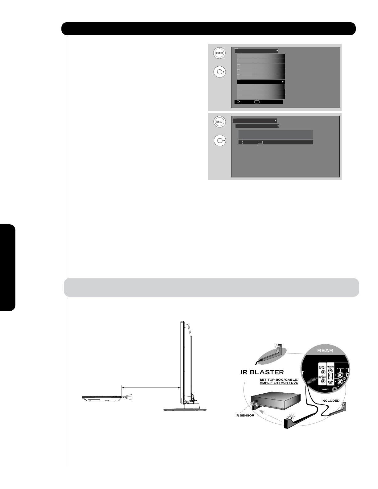
Setup
Set The IR Out
This feature allows the customer to hide and operate
external home theater components (VCR, DVD player or
OUT to return to previous menu.
NOTE : Extended Length option is not available for some kinds of external components. For those components
IR Out options :
Select Normal Length to pass the remote
control signal to the IR Out Terminal as is.
The reach of the original remote control to the
Select Extended Length to process the
remote control signal to the IR Out Terminal.
The reach of the original remote control to the
the Hitachi Plasma TV set with the provided IR Blaster
cables.
cable box) by using their original remote control through
Also called IR Passthru, this feature will let your TV
receive the (IR) infrarred control codes and transmit
them to your hidden equipment.
1. Use CURSOR PAD
or to highlight IR Out
function.
2. Use the CURSOR PAD
or to select
Normal Length or Extended Length option.
3. Press EXIT to quit menu or select SET THE IR
•
TV IR Receiver is 1m (max).
•
TV IR Receiver is 5m or more.
Setup
Setup The Menu Options
OR
OR
Set The Screen Saver
Set The Inputs
Set The AV Net
Set The Closed Captions
Set The IR Out
CableCARD Information
Select The Quick Start Option
Reset The Software
Move SEL Select
Setup
Set The IR Out
IR Out : Normal Length
Move SEL Return
The IR Out options (IR Passthru feature) are related to the distance between the original remote control
of the external equipment and the TV IR receiver in a straight line. The operation distance for Normal Length
and Extended Length options willl be reduced if the angle of the remote control position is changed.
use Normal Length option or point the original remote control directly at the external components.
On-Screen Display
IR Out (IR Passthru) Distance Specification
Hitachi Plasma
Rear Connection
Other Brand
Remote Control
Normal Length: 1 m or less
Extended Length: 5 m or more
IR Sensor
Hitachi Plasma
Side View
76
Page 77

Setup
CableCARD Information
After the CableCARD has been successfully installed,
you can access CableCARD Information menu in the
SETUP menu of the On-Screen Display.
Follow the instructions below to access the CableCARD
Information menu.
1. Press the MENU button on the Remote Control to
access the Main Menu screen.
2. Use the CURSOR PAD
to highlight SETUP in
the Main Menu and press the SELECT button.
3. Use the CURSOR PAD
to highlight CableCARD
Information and press the SELECT button.
4. To view the CableCARD ID and Host ID, use the
CURSOR PAD
to highlight CableCARD Info and
press the SELECT button.
NOTE: The Diagnostics Info. window is for
Service use only.
THINGS TO CHECK WHEN USING THE
CableCARD / CableCARD Services
1. Check that the CableCARD is properly inserted in
the CableCARD slot.
2. Remove the CableCARD by pulling
the CableCARD straight out.
Video
Audio
TV Guide On Screen
Channel Manager
Locks
Timers
Setup
Power Swivel
Move SEL Select
Setup
Setup The Menu Options
OR
Set The Screen Saver
Set The Inputs
Set The AV Net
Set The Closed Captions
Set The IR Out
CableCARD Information
Select The Quick Start Option
Reset The Software
Move SEL Select
Setup
CableCARD Information
OR
Select the button below to acess
CableCARD ID and Host ID.
Select the button below to access
CableCARD and Host Diagnostics.
Move SEL Return
CableCARD Info.
Diagnostics Info.
On-Screen Display
3. Visually inspect the CableCARD to ensure all pinholes are in good condition, with none blocked or
damaged.
4. Make sure the CableCARD is re-inserted in the
correct direction, then slowly push until it is fully
seated in the slot.
5. When the CableCARD is installed, note all screen
messages that appear (“CableCARD Installed”,
“Acquiring Data”, “CableCARD is not Installed”).
If the “CableCARD Installed” message does not
appear when card is installed, check the TV’s card
slot and CableCARD pins for obstructions or
damage.
6. If problems still remain, please contact your Cable
Service Provider.
NOTES:
1. When a CableCARD is installed, Auto
Channel scan will not be needed
because the channel list is automatically
loaded to the TV's channel memory.
2. The TV will take several minutes to
detect and recognize the presence of the
CableCARD. This process must be
completed before any CableCARD
information or Channel listings is
accessed.
In order to start cable service
for this device, please contact
your cable provider
CableCARD(tm): 123-456-789-1
Host: 123-456-789-1
Data: 123-456-789-1
Unit Address: 123-456-789-1
Press EXIT to return
77
Page 78

Setup
Select The Quick Start Option
This feature will select QUICK START UP options. Set
this feature to ON to have the TV tune channels (both
Analog and Digital) quickly when first turning the TV on.
Set this feature to OFF to save electricity. Selecting ON
for the QUICK START UP feature will activate the TV
tuners circuits when the TV is in “standby mode” which
is commonly referred to as “off”. This will allow you to
quickly tune to channels when first turning the TV on.
Digital signals often change and this feature will monitor
any changes and prepare the television to quickly
present a picture. A small amount of electricity is used
to continually monitor signals when this feature is
selected.
NOTE: 1. When setting the Quick Start option to ON
the option of Reset TV Settings will not operate
unless you turn ON/OFF the main power
button.
Reset The Software
This feature shows software information and easy
upgrade procedure. This function allows the TV software
to be upgraded by using a flash card (MMC/SD CARD).
If a future software upgrade is required for your TV,
HITACHI will notify and provide you with a flash
card. In order to receive written notification and the
flash card, please complete and return the warranty
card.
Setup
Setup The Menu Options
OR
OR
OR
Set The Screen Saver
Set The Inputs
Set The AV Net
Set The Closed Captions
Set The IR Out
CableCARD Information
Select The Quick Start Option
Reset The Software
Move SEL Select
Setup
Select The Quick Start OOption
Select ON to have the TV tune channels quickly at
1st turn on.
Select OFF to save electricity
Off On
Move SEL Select
Setup
Setup The Menu Options
Set The Screen Saver
Set The Inputs
Set The AV Net
Set The Closed Captions
Set The IR Out
CableCARD Information
Select The Quick Start Option
Reset The Software
Move SEL Select
1. Insert MMC/SD CARD.
2. Press the CURSOR PAD
UPGRADE NOW.
On-Screen Display
3. Press the SELECT button to select and start
or to highlight
OR
upgrading.
4. Unplug the AC power cord when the UPGRADE
is complete.
Setup
Reset The Software
MMC Software Upgrade : Vxxxx.xxxx
Please Insert MMC card
before upgrading.
Reset TV Settings
(Select "Yes" to return all settings
to the factory default after main power OFF/ON.)
Move
Upgrade Now
No Yes
SEL Return
NOTE: Any power interruption during the upgrade
process will cancel the upgrade. When this
happens, repeat the upgrade procedure.
Reset TV Settings
This function allows you to Reset all TV Settings to the original factory settings on all modes during the next main
power off/on.
1. Use CURSOR PAD , to highlight functions.
2. Press the SELECT button or CURSOR PAD to select Reset the Software Menu.
3. Use the CURSOR PAD to access the Reset TV settings option.
4. Select the "YES" option to Reset ALL the TV functions during the next main power off/on.
NOTE: 1. If YES is selected, ALL TV MENU SETTINGS will be reset to the original factory settings on all
modes during the next power off/on .
2. When the Quick Start Option has been set to ON or TV Guide On Screen
TM
is configured, this option
needs POWER OFF/ON operation by the Main Power SW.
78
Page 79

Power Swivel
Power Swivel
This feature controls the motorized stand. It allows
the customer to turn the Plasma Television left or right
using the remote control. This feature is only available
when the Table Top Stand is connected (see page 6).
1. Use the CURSOR PAD
or to unlock or lock
Video
Audio
TV Guide On Screen
Channel Manager
Locks
Timers
Setup
Power Swivel
Move SEL Select
the Power Swivel.
Exit the OSD menu system before controlling the
motorized stand.
2. Press the CURSOR PAD
to rotate the TV to
OR
the right.
3. Press the CURSOR PAD
the left.
to rotate the TV to
Power Swivel
Select
4. Release the CURSOR PAD to stop rotation.
NOTE: 1. The Power Swivel has a maximum turning angle of 30° (left and right).
2. Do not place any objects in the path of the plasma television when using the power swivel feature.
3. Before using the power swivel, please make sure that the path of the plasma television is clear of
any fingers, hands or any other body parts to avoid causing injury.
SEL Return
Locked
On-Screen Display
79
Page 80

Equipment Care and Troubleshooting
DO
Dust the screen and cabinet with a soft cloth.
Clean the screen with a soft cloth moistened in warm
water and dry with a soft cloth. A mild soap may be
used if the screen is extremely dirty.
Place your Plasma Television away from extreme heat,
humidity, and extremely dusty places.
Remove the plug from the wall outlet if your Plasma
Television will not be used for a long period of time, for
instance, when you go on vacation.
DO NOT
Do not clean your screen with strong cleaners, polishes
or a chemically treated cloth.
Do not place rubber or vinyl products or cellophane
tape on your Plasma Television.
Avoid repeatedly touching the screen.
Do not subject the remote control to shocks such as
dropping it on the floor, etc. This may cause damage to
the precision parts.
Avoid placing the remote control in a high humidity
place or getting it wet. Do not leave it on or near a
heater. Excessive heat or moisture may cause the unit
to fail.
When the batteries run down, remote control operation
will become erratic or become unresponsive. Replace
the old batteries with two new “AA” size batteries. Do
not use an old battery with a new battery.
Exposing the screen to direct sunlight for a long period
of time or heat may cause damage to the plasma
screen.
TROUBLESHOOTING
Your HITACHI Plasma Television incorporates advanced power surge protection technology designed to protect
against component or circuit damage due to external or internal voltage power surges.
IF YOUR TELEVISION SHOULD APPEAR TO HAVE A LOSS OF POWER, PLEASE FOLLOW THIS
PROCEDURE:
1. Press the POWER
SWITCH (ON/OFF
ct
n is corre
SWITCH) once.
2. If there is still no power,
wait 30 seconds and
press the POWER
SYMPTOMS
SWITCH again.
3. If there is still no power,
Useful Information
unplug the power cord
from the wall. Wait 30
seconds and plug the
power cord back in.
Press the POWER
SWITCH again.
This protective technology
Poor reception on some channels
should provide for years of
No Picture, no sound
Sound OK, picture poor
Picture OK, sound poor
Picture blurred
Lines or streaks in picture
Picture rolls vertically
lasting entertainment from
your HITACHI Plasma
Television.
CHECK THESE ITEMS AND
TRY THESE ADJUSTMENTS
No color
Poor color
Be sure external connectio
Be sure
쏹쏹
쏹
쏹
쏹
쏹
쏹
쏹
power cord is plugged in
Try a nother channel (station trouble)
Be sure TV is switched''ON"
Check antenna connections (back of TV)
쏹쏹쏹쏹
쏹쏹
쏹쏹쏹쏹
쏹쏹쏹쏹
쏹쏹쏹쏹
쏹쏹쏹쏹
쏹쏹쏹쏹
쏹
쏹쏹쏹쏹
쏹쏹쏹쏹
Check antenn
wire
rence
antenna
a for broken lead-in
Check for lo
Check outside
쏹쏹
쏹
쏹
쏹
쏹
ess control
cal interfe
Adjust Contrast control
Adjust Brightn
Adjust Color control
Adjust Tint control
쏹
쏹
쏹
쏹
Adjust Volume control
80
Page 81

Reception Problems
IGNITION NOISE:
Black spots or horizontal streaks may appear, picture may flutter or drift.
Usually caused by interference from automobile ignition systems, neon lamps,
electrical drills, and other electrical appliances.
GHOSTS:
Ghosts are caused by the television signal following two paths. One is the
direct path and the other is reflected from tall buildings, hills or some other
objects. Changing the direction or position of the antenna may improve
reception. Ghosting may also be caused by defects in the antenna system such
as unshielded leads or connecting several sets to the same antenna without
using multiple antenna couplers.
SNOW:
If your receiver is located in the fringe area of a television station where the
signal is weak, your picture may be marred by the appearance of small dots.
When the signal is extremely weak, it may be necessary to install a special
antenna to improve the picture.
RADIO FREQUENCY INTERFERENCE:
The interference produces moving ripples or diagonal streaks, and in some
cases, causes loss of contrast in the picture.
• PREVENTION OF AN OBSTACLE TO RADIO RECEIVERS
This television has been designed pursuant to the FCC class B Rules. This is to prevent a problem to Radio
receivers. If this television causes a problem to Radio receivers, then take the following steps:
- Keep the television away from Radio.
- Adjust Radio antennas in order for the television not to receive interference.
- The antenna cable of Radio should be kept away from the television.
- Use a coaxial cable for antenna.
You can check if this television influences Radio receivers by turning off all other equipment other than the television.
If you find a problem receiving Radio when using the television, check the instructions mentioned above.
BLOCK NOISE (DIGITAL INPUT):
Fuzzy blocks may appear in some area or the whole area of the screen. This is
usually caused by interference from automobile ignition systems, neon lamps,
electrical drills, ghosting of the image and weak signals.
BLACK SCREEN:
When using an antenna, weak signals will display a black screen. It may be
necessary to upgrade your antenna.
Useful Informationl
NOTE: The TV set can generate sound distortion in external devices such as a radio. Please separate radio
equipment from the TV set to a considerable distance.
81
Page 82

Useful Info
AGENCY REGULATORY INFORMATION
Federal Communications Commission Notice
This equipment has been tested and found to comply with the limits for a Class B digital device, pursuant to Part
15 of the FCC Rules. These limits are designed to provide reasonable protection against harmful interference in
a residential installation. This equipment generates, uses and can radiate radio frequency energy and if not
installed and used in accordance with the instructions, may cause harmful interference to radio
communications. However, there is no guarantee that interference will not occur in a particular installation. If this
equipment does cause harmful interference to radio or television reception, which can be determined by turning
the equipment off and on, the user is encouraged to try to correct the interference by one or more of the
following measures:
• Reorient or relocate the receiving antenna.
• Increase the separation between the equipment and the receiver.
• Connect the equipment into an outlet on a circuit different from that to which the receiver is connected.
• Consult the dealer or an experienced radio/television technician for help.
FCC Information
This device complies with part15 of the FCC Rules.Operation is subject to the following two conditions :
(1) This device may not cause harmful interference and (2) This device must accept any interference
received, including interference that may cause undesired operation.
Modifications
The FCC requires the user to be notified that any changes or modifications made to this device that are not
expressly approved by Hitachi America ,Ltd. Home Electronics Division may void the user’s authority to
operate the equipment.
Cables
Connections to this device must be made with shielded cables with metallic RFI/EMI connector hoods to
maintain compliance with FCC Rules and Regulations.
Any cables that are supplied with the system must be replaced with identical cables in order to assure
compliance with FCC rules. Order Hitachi spares as replacement cables.
Note
This Plasma Television receiver will display television closed captioning, ( or ), in accordance with
paragraph 15.119 and 15.122 of the FCC rules.
INDUSTRY CANADA AGENCY REGULATORY INFORMATION
Cable Compatible Television Apparatus- Tèlèvision câblocompatible, Canada.
Useful Information
82
Page 83

Features and Specifications
Features:
New 1080 Full HD Plasma Display Panel
•
• New Easy-to-Use On-Screen Menu Control (3
Language)
•
Region 5 (Downloadable V-Chip)
IR OUT/G-LINKTM System Control
•
- Control your components with one remote
control (AV Net).
- IR Pass-thru
Preprogrammed Remote Control
•
Power Swivel Stand
•
•
Picture Enhancement: Smooth Motion Film Process
•
Input Signal Identification
•
CableCARD compatible - Contact your local cable
operator for more information
•
HDMI (High Definition Multimedia Interface)(High
Bandwidth Digital Content Pro tection V1.1
Compatible)
•
Photo Input
•
TV Guide On Screen
Technology•
• Lip Sync Control
Game Mode
Video:
•
1920 x 1080 Display Resolution
•
• ALiS (Alternate Lighting of Surfaces Technology)
•
•
•
High-Contrast Pure-Color Glass Shield
•
Wide Viewing Angle
Color Temperature Presets: High, Standard,
•
Medium and Black/White.
Multiple Screen Fill Modes
•
(4:3 Standard/4:3 Expanded/4:3 Zoom 1/
4:3 Zoom 2/16:9 Standard1/Standard2/16:9 Zoom)
4MB 10-bit 3D Y/C Comb Filter
•
• Picture Modes :Day(Normal), Day(Dynamic) and Night
Inputs:
•
Power Input . . . . . . . . . . . . . . . . . . . . .AC 120V, 60Hz
Power Consumption
•
Average Power : . . . . . . . . . . . . . . . . . . . . . . . . . . 364 W
Maximum Power :. . . . . . . . . . . . . . . . . . . . 605 W, 5.7 A
Antenna input impedance . . . . . . . . . . . . . . . .75 Ohm
•
Channel coverage . . . . . . . . . . . . . . . . . . . . . . . 191ch.
•
VHF-Band . . . . . . . . . . . . . . . . . . . . . . . . . . . . . 2 ~ 13
UHF-Band . . . . . . . . . . . . . . . . . . . . . . . . . . . . 14 ~ 69
CATV Mid Band
. . . . . . . . . . . . . . . . . . . . . . . . . . . . . . . . . . . . . . . . . A-I
Super
Hyper
Ultra Band . . . . . . . . . . . . . . . . . . . . . . . W+29 - W+94
Television System . . . . . . . . . . . . . . . NTSC Standard
•
Video . . . . . . . . . . . . . . . . . . . . . . . . 1.0Vp-p, 75 Ohm
•
S-Video
•
Luminance (Y) . . . . . . . . . . . . . . . . . 1.0Vp-p, 75 Ohm
Chrominance (C) . . . . . . . . . . . . . 0.286Vp-p, 75 Ohm
Component Video
•
Luminance (Y) . . . . . . . . . . . . . . . . . 1.0Vp-p, 75 Ohm
Chrominance (PB/PR) . . . . . . . . . . . 0.7Vp-p, 75 Ohm
Audio input Impedance . . . . . . . . . . . . . . . . 270k Ohm
•
Average input level . . . . . . . . . . . . . . . . . . . 470mVrms
•
HDMI . . . . . . . . . . . . . . . . . . . . . . . . . . . . . . . . (19 PIN)
•
(for your Digital Camera SD Memory Card)
Band . . . . . . . . . . . . . . . . . . . . . . . . . . . . . . J-W
Band
. . . . . . . . . . . . . . . . . . . . . . . W+1 •- W+28
ATSC Standard (8 VSB, 64-QAM, 256-QAM)
TM
. . . . . . . . . . . . . . . . . . . . . . A-5 •~
A-1
Outputs:
Video1.0Vp-p. 75 Ohm
•
Audio . . . . . . . . . . . . . . . . . . . . . . .470mVrms, 1k Ohm
•
Optical Out (Digital Audio) . . . . . .1 Optical Connector
•
Audio:
MTS Stereo/SAP
•
Bass Boost
•
Surround Sound
•
20W
•
Soft Mute (50%)
•
Supplied Accessories:
•
Remote Control
•
Batteries (AA)
•
6' AC Power cord cable
•
Power Swivel Table Top Stand (included in a box)
•
Power Swivel cable
2 IR Blaster Cables
Wire clamp
•
Optional Accessories:
For U.S. Models: Please access our website:
•
www.hitachi.us/tv
INPUTS/OUTPUTS
Wideband Component Y, Pb,Pr . . . . . . . . . . . . . . . . 2
•
Composite Video . . . . . . . . . . . . . . . . . . . . . . . . . . . . 4
•
S-Video . . . . . . . . . . . . . . . . . . . . . . . . . . . . . . . . . . . 1
•
Antenna (RF) Inputs . . . . . . . . . . . . . . . . . . . . . . . . . . 1
•
Audio Output . . . . . . . . . . . . . . . . . . . . . . . . . . . . . . . 1
•
Monitor Output . . . . . . . . . . . . . . . . . . . . . . . . . . . . . 1
•
Optical Output . . . . . . . . . . . . . . . . . . . . . . . . . . . . . . 1
•
1
HDMI . . . . . . . . . . . . . . . . . . . . . . . . . . . . . . . . . . . . . 3
•
RS232C Interface . . . . . . . . . . . . . . . . . . . . . . . . . . . 1
•
IR Blaster . . . . . . . . . . . . . . . . . . . . . . . . . . . . . . . . . . 2
•
•
•
•
•
•
TM
G-LINK
CableCARD Slot
Upgrade Card Slot
Swivel Output . . . . . . . . . . . . . . . . . . . . . . . . . . . . . . 1
Photo Input . . . . . . . . . . . . . . . . . . . . . . . . . . . . . . . . 1
. . . . . . . . . . . . . . . . . . . . . . . . . . . . . . . . . . . . 1
. . . . . . . . . . . . . . . . . . . . . . . . . . . . 1
. . . . . . . . . . . . . . . . . . . . . . . . . . 1
SPECIFICATIONS
Pixel Pitch . . . . 0.576(horiz.) x 0.580(vert.) mm.
•
FCC class: . . . . . . . . . . . . B for Consumer Use
•
• Power Requirements . . . . . . 108-132VAC, 60Hz
Operating Temperature . . . . . . . . . . . . . 41°F to 95°F.
•
1
Screen mode availability varies by input format
HDTV Televisions display HDTV only when an HDTV source is available.
All specifications, weights, and dimensions are subject to change without
prior notice. Please access www.hitachi.us/tv for detailed specifications
and dimensions for custom installations.
UltraVision Digital is a registered trademark of Hitachi Home Electronics
(America), Inc.
㪚㪦㪧㪰㪩㪠㪞㪟㪫㩷㪺㩷㪈㪐㪐㪐㪄㪉㪇㪇㪎㩷㪤㪦㪥㪫㪘㪭㪠㪪㪫㪘㩷㪪㪦㪝㪫㪮㪘㪩㪜㪃㩷㪠㪥㪚㪅㩷㪘㪣㪣㩷㪩㪠㪞㪟㪫㪪㩷㪩㪜㪪㪜㪩㪭㪜㪛㪅
Interface are trademarks or registered trademarks of HDMI Licensing
LLC.
*Manufactured under license from Dolby Laboratories. “Dolby” and the
double-D symbol are trademarks of Dolby Laboratories.
HDMI, the HDMI logo and High-Definition Multimedia
Useful Informationl
83
Page 84

Set Dimensions
50 Inch Models (Includes Table Top Stand) Weight (lbs./kg): 109.7/49.8
Useful Information
Rear View, Use as Reference for Wall Mount Bracket
A
Units
Inches
mm 1240.00 65.00 65.00 880.90 820.50 513.40 505.90 445.50 1105.92 626.40 128.50 92.50 36.00 422.60 305.00 630.00 305.00 298.00 308.00 214.50
84
BCDEFGH I JKLMNOPQRST
48-13/16 2- 9/16 2- 9/16 34-11/16 32- 5/16 20- 3/16 19-15/16 17- 9/16 43- 9/16 24-11/16 5- 1/16 3-10/16 1- 7/16 16-10/16 12 24-13/16 12 11-12/16 12- 2/16 8-7/16
Page 85

Hitachi
Service Hotline
To locate an authorized HITACHI
service facility in the continental
U.S.A. and Canada,
DIAL TOLL FREE
7 days a week, 24 hours a day
1-800-HITACHI
(1-800-448-2244)
HITACHI AMERICA, L
HOME ELECTRONICS DIVISION
HITACHI has made every effort to assure you hours of
trouble free operation from your unit. However, should
you require service, a network of HITACHI Authorized
Service Facilities has been established in all 50 states
and Puerto Rico. Each facility will provide you with
convenient and expedient assistance. Our service
hotline operator will direct you to the HITACHI
Authorized Service Facility nearest you. Just present
proof of purchase and/or delivery receipts to the
Hitachi Authorized Service Facility, and service will be
rendered in accordance with the terms of the limited
warranty as stated on your warranty card or operating
guide.
Should you have any questions regarding warranty,
service, operation, or technical assistance, please
contact:
Hitachi America, LTD.
Home Electronics Division
900 Hitachi Way
Chula Vista, CA 91914-3556
TD.
HITACHI CANADA, LTD.
DIGITAL MEDIA DIVISION
Should you have any questions regarding warranty,
service, operation, or technical assistance, please
contact:
In Canada: 1-800-HITACHI (1-800-448-2244)
Monday – Friday (EST).........................9:00am – 7:00pm
Saturday (EST) .....................................9:00am – 5:00pm
Look for your French Manual on the outside of the
box. If the manual is missing, call 1-800-HITACHI
(1-800-448-2244) for a copy.
Pour de plus amples renseignements sur le service
durant la période couverte par la garantie, sur le
fonctionnement ou pour de l’assistance technique
communiquez avec:
Au Canada: 1-800-HITACHI (1-800-448-2244)
Lundi - Vendredi L’EST ........................9:00am – 7:00pm
Samedi L’EST.......................................9:00am – 5:00pm
La version français de votre manual se trouve a
l’exterieur de la boîte. Si le manuel est manquant,
coposez le 1-800-HITACHI (1-800-448-2244) pour
obenir votre copie.
Useful Informationl
HITACHI CANADA, LTD.
1-2495 Meadowpine Blvd.
Mississauga, Ontario L5N 6C3
85
Page 86

Service Information
When you call HITACHI SERVICE HOTLINE they will require some information related
to the TV MODEL NAME and SERIAL # in order to give you the proper support. This
information is located on the back of the TV and also on the RIGHT SIDE of your TV
set. Please follow the next steps to find this information and then provide to SERVICE.
쐃
Look on the right side of the TV.
쐇
Locate the LABEL where it shows the information
related to MODEL NAME and SERIAL #.
쐋
HITACHI Service Department will require this
information in order to give you the proper support
regarding your questions.
쐃
Useful Information
86
쐇
Page 87

TELEVISOR DE PLASMA
Guía de funcionamiento para P50V701
INSTRUCCIONES IMPORTANTES DE SEGURIDAD............................................................ 88-89
USO POR PRIMERA VEZ ................................................................................................. 90-111
EL CONTROL REMOTO .................................................................................................... 112-128
MENÚ EN PANTALLA ....................................................................................................... 129-165
INFORMACIÓN ÚTIL .......................................................................................................166-172
Page 88

Instrucciones Importantes de Seguridad
PUNTOS DE SEGURIDAD QUE USTED DEBE SABER
SOBRE SU TELEVISOR DE PLASMA HITACHI
Nuestra reputación se ha formado en base a la calidad,
desempeño y facilidad de servicio de los televisores de
plasma HITACHI.
La seguridad está en primer lugar en nuestra mente al
diseñar estas unidades. Para ayudarlo a operar estos
productos en forma apropiada, esta sección ilustra datos
de seguridad que serán de beneficio para usted. Léalos
cuidadosamente y aplique los conocimientos adquiridos
para operar con propiedad su televisor de plasma
HITACHI.
Complete su tarjeta de garantía y envíela por correo a
HITACHI. Esto le permitirá a HITACHI notificarlo
rápidamente en el caso improbable de que se descubra
un problema de seguridad en el modelo de su televisor.
Siga todas las advertencias e instrucciones marcadas
en este televisor de plasma.
PRECAUCIÓN
RIESGO DE DESCARGA
EL
É
CTRICA NO ABRIR
AVISO: PARA REDUCIR EL RIESGO DE DESCARGA ELECTRICA, NO
RETIRE LA CUBIERTA NI EL PANEL POSTERIOR. EN EL INTERIOR
DEL APARATO NO EXISTEN PARTES QUE DEBAN SER REPARADAS POR EL USUARIO. SOLICITE SERVICIO O REPARACIÓN
A PERSONAL CALIFICADO.
El símbolo del rayo dentro de un triángulo
equilátero tiene por finalidad alertar al usuario
acerca de la presencia de voltaje peligroso (sin
aislamiento) en el interior del producto, que
puede tener la intensidad suficiente como para
considerar un riesgo de descarga eléctrica.
El signo de exclamación dentro de un triángulo
equilátero tiene por finalidad alertar al usuario
de instrucciones importantes de operación y
mantenimiento (servicio) en la literatura que
acompaña a este aparato.
10. Proteja el cable de alimentación para que no se pise ni
esté retorcido, especialmente en las clavijas, los
receptáculos y el punto por el que sale del aparato.
11. Utilice únicamente los accesorios especificados por el
fabricante.
12. Utilice únicamente el carro, mueble, tripie,
soporte o mesa especificado por el
fabricante o de venta con el aparato. Si
utiliza un carro, tenga cuidado al mover el
aparato para evitar que se caiga y provoque daños
personales.
13. Desconecte el equipo durante tormentas eléctricas o
cuando no lo vaya a utilizar durante periodos
prolongados.
14. Para tareas de mantenimiento, diríjase a personal
calificado. Será necesario recurrir a tareas de
mantenimiento si el aparato sufre daños de cualquier
tipo, si el cable de alimentación o la clavija están
dañados, si ha caído líquido u otros objetos en el
aparato o si éste ha sido expuesto a la lluvia o
humedad, si no funciona con normalidad o se ha
caído.
15. Los televisores están diseñados para cumplir con los
estándares de seguridad recomendados para
inclinación y estabilidad. No aplique fuerza excesiva a
la parte superior o frontal de gabinete que pudiera
hacer que el televisor se caiga causando daño del
producto y/o daño personal.
16. Siga las instrucciones de montaje en la pared, estante
o techo según lo recomendado por el fabricante.
17. Una antena exterior no deberá ser instalada en la
cercanía de líneas de alimentación externas ni de
otros circuitos de iluminación eléctrica.
18. Si se conecta una antena externa ó sistema de cable
a la unidad, cerciórese de que el sistema de antena ó
cable está conectado a tierra para darle protección
contra sobretensión y acumulación de carga estática.
La Sección 810 del Código Nacional de Electricidad,
ANSI/NFPA 70-1984, proporciona información con
respecto a como poner a tierra el mástil apropiadamente
y la estructura de sostenimiento, al poner a tierra el
alambre de entrada a una unidad de descarga de la
antena, tamaño de los conectores para poner a tierra,
locacalidad de la unidad de descarga de antena,
conexión de los electrodos a tierra y los requisitos
para el electrodo que pone a tierra.
LEA ANTES DE HACER FUNCIONAR EL EQUIPO
Siga todas las advertencias e instrucciones indicadas en
este televisor de plasma.
1. Lea estas instrucciones.
2. Conserve las instrucciones.
3. Tomar en cuenta todos los avisos.
4. Siga todas las instrucciones.
5. No utilice este aparato cerca del agua.
6. Limpie el equipo con un paño seco.
7. No bloquee las rendijas de ventilación. Instale el
equipo según las instrucciones del fabricante.
8. No lo instale cerca de fuentes de calor, como
radiadores, registros de calor, hornos o demás
aparatos (incluidos amplificadores) que produzcan
calor.
9. No altere la función de seguridad de la clavija de tipo
conexión a tierra. La clavija de tipo conexión a tierra
tiene dos terminales y una tercera terminal de
conexión a tierra. La tercera terminal se incluye para
su seguridad. Si la clavija suministrada no encaja en
la toma, póngase en contacto con un electricista para
88
que cambie el receptáculo (enchufe).
NEC - CODIGO NACIONAL DE ELECTRICIDAD
ABRAZADERA
DE TIERRA
EQUIPO DE SERVICIO ELECTRICO
ABRAZADERAS DE TIERRA
ALAMBRE DE ENTRADA DE LA ANTENA
UNIDAD DE DESCARGA DE LA ANTENA
(NEC, SECCION 810-20)
CONDUCTORES DE PUESTA A TIERRA
(NEC, SECCION 810-21)
SERVICIO DE ALIMENTACION DE SISTEMA
ELECTRODO DE PUESTA A TIERRA
(NEC ART 250, PARTE H)
Nota para el instalador del sistema CATV. Este
recordatorio se provee para llamar la atención del
instalador de sistema CATV hacia el Artículo 820-44 de la
NEC que brinda guías para una puesta a tierra apropiada
y en particular, especifica que la tierra del cable debe
conectarse al sistema de tierra del edificio, tan próximo a
la entrada de cable como sea más práctico.
Page 89

Instrucciones Importantes de Seguridad
Fuente de energía
Este televisor de plasma esta diseñado para operar con
corriente CA, 120 voltios 60 Hz. Inserte el cable de
electricidad en un tomacorriente de 120 voltios a 60 Hz.
El cable se utiliza como dispositivo de desconexión y
continua estando disponible.
Para impedir descarga eléctrica, no utilice la clavija
(polarizada) del televisor de plasma con una extensión,
receptáculo u otro enchufe a menos que los terminales y
el terminal de tierra puedan insertarse completamente
para evitar que la terminal este expuesta.
Nunca conecte el televisor de plasma a 50 Hz, corriente
directa o cualquier otro voltaje que no sea el especificado.
Precaución
Nunca quite la tapa trasera del televisor de
plasma ya que puede exponerlo a voltajes
muy altos y a otros peligros. Si el televisor no
funciona en forma apropiada, desenchufe el
televisor de plasma y llame a su distribuidor
o centro de servicio autorizado.
Precaución
Ajuste solamente los controles que se incluyen en las
instrucciones, ya que cambios inapropiados o
modificaciones que no estén expresamente aprobadas
por HITACHI podrían anular la garantía.
Visión pública de material con derechos de autor
La visión pública de programas transmitidos por
estaciones de televisión o compañías de cable, así como
programas de otras fuentes, puede requerir autorización
previa del difusor o propietario del material de programa
de video.
Este producto incorpora la tecnología de protección de
derechos de autor, que está protegida por demandas de
métodos de ciertas patentes de EE.UU. y otros derechos
de propiedad intelectual pertenecientes a Macrovision
Corporation y otros propietarios de derechos. El uso de la
tecnología de protección con derechos de autor debe ser
autorizada por Macrovision Corporation, y está autorizada
sólo para uso en el hogar y otros usos limitados al
consumidor a menos que Macrovision autorice lo
contrario. Está prohibida la ingeniería inversa o el
desmontaje.
Nota
Este televisor digital es capaz de recibir programación
básica análoga, básica digital de televisión por cable,
mediante la conexión directa a un sistema de cable que
provea tal programación. Se requiere una CableCARD
provista por su operador de cable para ver canales digitales
encriptados. Ciertos servicios de cable digital interactivos tales
como video-on -demand (sobre pedido), una guía de programas
mejorada del operador de cable y servicios de transmisión de
datos por televisión pueden requerir el uso de un decodificador.
Para mayor información llame a su compañía de cable local.
Advertencia
• Para reducir el riesgo de fuego o shock eléctrico, no
exponga el aparato a lluvia o humedad.
• El televisor de plasma no se debe exponer a filtrado o
salpicado de líquidos y a objetos con líquidos, tales
como floreros que no se deben colocar sobre el
televisor.
• Este aparato se debe conectar a la red de electricidad
con una conexión de protección a tierra.
Nota
• No existen partes remplazables por el usuario dentro
del televisor de plasma.
• Los números de serie y modelo se indican en la parte
posterior y el lado derecho del televisor de plasma.
Prevención de daños a la pantalla
La proyección continua en pantalla de imágenes tales
como videojuegos, Mercado bursatil, gráficos generados
por computadora, y otros patrones fijos (sin movimiento)
pueden quedar impresos en forma permanente en la
pantalla de su televisor. Tales "DAÑOS A LA PANTALLA"
constituyen un mal uso y NO ESTÁN CUBIERTOS por su
Garantía de Fábrica Hitachi.
Si se dejan imágenes fijas en la pantalla por más de 2.5
minutos, la función de protección iniciará automáticamente
de manera que el contraste se reduce para minimizar la
retención de imagen en la pantalla de plasma.
Por favor note que esto no es un defecto sino una medida
para minimizar la retención de imagen.
El contraste original se restablecerá después de desplegar
imágenes en movimiento por aproximadamente 6 minutos.
El contraste original puede ser restablecido rápidamente
apagando y encendiendo el televisor con el control
remoto o con el interruptor principal del televisor.
Aviso sobre el Plomo
Este producto contiene plomo. Deseche este producto de
acuerdo a las leyes ambientales aplicables. Para
información sobre reciclado y desecho del producto,
contacte su agencia gubernamental local o en www.eRe-
cycle.org (en California) a Electronic Industries Alliance
en www.eiae.org (en EE.UU.) o a Electronic Product
Stewardship Canada en www.epsc.ca (en Canadá).
PARA MAYOR INFORMACIÓN, LLAME AL 1-800-HITACHI
.
89
Page 90

Giratoria Automática
Accesorios
Asegurarse de que tiene los siguientes accesorios antes de desechar el material de empaque.
쐃
Control Remoto
Uso por primera vez
쐇
Dos baterías
tipo “AA” 1.5V
쐏
Cable de energía
쐋
Base Giratoria
Automática (incluída)
쐄
Cable para Base
쐂
Dos Cables IR Blaster
쐆
Sujetador de Cables
Para modelos de U.S.A. :
Para accesorios opcionales, visitar nuestro sitio de internet : www.hitachi.us/tv
PRECAUCIÓN: 1. El montaje en el techo no es recomendable. Montar el panel en el techo no provee
la adecuada ventilación a lo electronico ó el apropiado suporte al panel frontal de
vidrio. Este televisor de plasma está diseñado para una inclinación máxima de 45°
en vertical.
2. Esta base es solo para los modelos P50V701. El uso con otros aparatos
no indicados puede causar inestabilidad ocasionando daños personales.
3. La base para la pared para los modelos de 50" es WM07S. Favor de ver la página
93 para información importante relacionada con la base de la pared. La base es
un accesorio opcional (No está Incluida).
쐃
Control Remoto CLU-4374A
(No. Parte HL02404).
쐇
Dos baterias tipo "AA" , 1.5V .
쐋
Base giratoria Automática
(No. Parte QJ03754).
쐏
Cable de energía (No. Parte EV01841).
INSTALACIÓN Y REMPLAZO DE LAS BATERIAS DEL CONTROL REMOTO
1.
Abrir la cubierta de las baterias del control remotopresionando la pestaña para quitar la cubierta.
2.
Colocardos baterias tipo “AA” para elcontrol remoto
resortes y luego sacarlas.
3. Coincidir las marcas de las baterias (+) y (-) con las marcas
del compartimiento.
4. Insertar la parte inferior de la batería, el lado (-) neg, en el compartimiento primero , luego empujar hacia los resortes e insertar
la parte superior de la batería
forzar la batería dentro del compartimiento.
5. Colocar de nuevo la cubierta.
PRECAUCIÓN : No coloque la baterias con la polaridad ‘+’ y ‘-’ invertidas esto puede causar que
las baterias se derramen dentro del compartimiento.
, el lado (+) pos, en su lugar. No
쐄
Cable para Base Giratoria Automática
(No. de Parte EW08433).
Dos Cables IR Blaster
쐂
(No. de Parte EY01641).
쐆
Sujetador de Cables
.Alr
emplazar las baterias, empujar hacia los
VistaPosterior (ControlRemoto)
Presionar la pestaña para quitar la cubierta
.
90
Page 91

Cómo colocar su nuevo televisor de plasma HITACHI
Como tomar medidas para evitar que el televisor de plasma se incline e impedir posibles daños, es importante
montar la unidad en una superficie estable y lisa.
Asegurando a una pared
1. Usando cable metálico (Dos puntos) sujetar
el televisor con los tornillos de agarre en la parte
posterior del Televisor como se muestra.
ANTENA
A menos que su televisor de plasma esté conectado a
un sistema de televisión por cable o a un sistema de
antena externa, se recomienda una buena antena de
televisión color para mejor rendimiento.Sin embargo, si
Cable
se encuentra en un área con señal excepcionalmente
buena sin interferencia y sin fantasmas en la imagen,
una antena interior puede ser suficiente.
UBICACIÓN
Seleccione un área donde la iluminación interior o la luz
2. Mantenga el televisorde plasma a 4 pulgadas (10 cm)
de la pared excepto cuando lo monta usando un
soporte de montaje a la pared.
3. Asegure el televisor a la pared como se muestra
en la fig.
A
B
solar no se diriján directamente sobre la pantalla.
También asegúrese de que la ubicación seleccionada
permite un flujo libre de aire hacia y desde la tapa
posterior del equipo. Para evitar el aumento de
temperatura interna, mantenga un espacio de 4
pulgadas (10 cm) desde los lados y la parte posterior del
televisor, y 30 cm (12 pulgadas) desde la parte superior
A B
50"
4 in.
10 cm
12 in.
30 cm
del televisor a la pared. Para evitar deformaciones
del gabinete, cambios en el color del gabinete y mayor
oportunidad de falla en el equipo, no coloque el televisor
donde las temperaturas puedan volverse excesivamente
cálidas por ejemplo, a laluz solar o cerca de uncalefactor,
etc.
(a)Base Giratoria
SIN USARLA
(b)Base Giratoria
USANDOLA
30 cm (12 pulg.)
* Favor de ajustar la longitud del cable para evitar
que la TV toque la pared al girarla.
10 cm (4 pulg.)
10 cm (4 pulg.)
NOTAS: 1. No bloquee los ranuras de ventilación del
televisor de plasma. El bloqueo de agujeros
de ventilación podría causar fuego o defectos.
2. En caso de un síntoma anormal, desenchufe
el cable de CA.
3. Si compró el soporte de montaje a la pared,
solicite un instalador profesional.
No lo instale por su cuenta.
4. Instale la unidad en un área apropiada donde
no se expongaa nadie al peligro de golpearse
(por ejemplo, manos cabeza o cara) contra el
CONEXIÓN DE CABLE PARA BASE GIRATORIA
Conecte un extremo del cable al conector "SWIVEL" de la
parte posterior del televisor de plasma. Conecte el otro
extremo del cable al conector en la base giratoria. Para
ver información más a detalle, por favor vea la instrucción
de instalación en la página siguiente.
borde de la unidad y causar daño personal.
5. Si la opción de la base giratoria nose usara,
el televisor de Plasma debe asegurarse
a la pared como en la fig.(a).
6. Si la opción de la base giratoria se usa,
el televisor de Plasma debe asegurarse
ANGULO DE ROTACIÓN
El máximo angulo de rotación es 30° (Izq. y Der.). No
colocar objetos en el paso del televisor al usar la
base giratoria.
a la pared como en la fig. (b).
Precaución al mover la unidad principal
Como este producto es pesado, para moverlo, se requieren
dos personas para transportarlo con seguridad. Cada vez
que se mueva la unidad debe levantarse hacia adelante
C
CD
10.8 in.
50"
D
27.5 cm
usando la parte superior y la base a ambos lados del
televisor para lograr estabilidad.Cuando mueva el televisor,
levante de las agarraderas que sostienen la estructura
luego tomar de la parte superior como se muestra :
15.35 in.
39 cm
Uso por primera vez
50”
91
Page 92
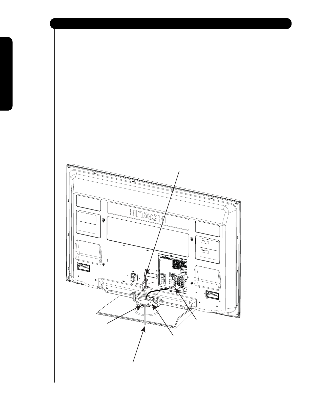
Cómo colocar su nuevo televisor de plasma Hitachi
INSTRUCCIÓN DE COMO COLOCAR EL CABLE DE AC Y EL CABLE DE LA BASE GIRATORIA
El cable de AC y el cable de la base giratoria que vienen incluidos en su nuevo Televisor de Plasma
necesitan ser ensamblados correctamente para evitar que se desconecte al girar el Televisor con su base.
En el televisor existen 2 sujetadores de plástico localizados en la parte posterior del Televisor para
sujetar el cable de AC y el cable de la base giratoria . Favor de seguir las siguientes intrucciones.
쐃
Pasar el cable de AC a través del sujetador #1 y
conectarlo al televisor. Jalar el extremo del sujetador
para sujetar el cable de AC con el televisor.
쐇
Uso por primera vez
Conecte un extremo del cable de la base giratoria al
conector "SWIVEL" de la parte posterior del televisor de
plasma. Conecte el otro extremo del cable al conector
en la base giratoria.
Los cables de señal, el cable de AC y para la base
쐋
giratoria pueden ser sujetados con el sujetador #2
(incluído en la bolsa de accesorios).
Sujetador #1 : Pasar el cable de AC a través de este
쐃
sujetador primero; luego jalar el extremo
para sujetar el cable al televisor.
Conector "Swivel" en la
쐇
Base Giratoria Automática.
92
Cable de AC
Conector "Swivel" en la parte posterior
쐇
del televisor de Plasma.
Sujetador #2: Usar para sujetar el cable de AC
쐋
con el resto de cables usados en el
televisor. Para este modelo insertar
este sujetador en el agujero central
de la base de metal como se muestra.
Page 93

Cómo colocar su nuevo televisor de plasma Hitachi
CONFIGURACIÓN PARA MONTAJE EN LA PARED
PASO (1) :
Localizar el metal de la BASE en la parte posterior del televisor. Este metal es usado para sostener el televisor y la
base; se tienen que quitar 4 tornillos de la BASE para separar el televisor de la base.
METAL de la BASE
Uso por primera vez
PASO (2):
Quitar los 4 tornillos de la BASE de metal del Televisor , ahora la BASE puede ser separada del Televisor.
Para dimensiones del ensamble en la PARED referirse a la página 170.
4 Tornillos
METAL de la BASE
BASE del TELEVISOR
Para el Modelo P50V701
PRECAUCIÓN - Este televisor de Plasma solo puede usar la base para la pared WM07S de Hitachi. Al usar otra
base puede causar inestabilidad en el televisor provocando posibles heridas personales.
NOTA: Use la base para pared (WALL MOUNT) para el Televisor de Plasma de acuerdo al tamaño.
Visite nuestro sitio de internet: www.hitachi.us/tv para accesorios de su Televisor.
93
Page 94

Cómo configurar su nuevo televisor de plasma Hitachi
VISIÓN
La mejor posición para ver la imagen es en frente
del televisor y de 10 a 18 pies lejos de la pantalla.
Durante las horas del día, las reflexiones o reflejos
R
S
de luz externa pueden aparecer en la pantalla. Si
esto sucede, pueden ser usadas cortinas para reducir el
reflejo o la TV puede cambiarse de lugar en el cuarto.
4" Minimo
70
MEJOR
ANGULO DE
Si el audio del televisor es conectado a las bocinas de
un sistema de alta fidelidad (Hi-Fi), la mejor
Uso por primera vez
calidad de audio se obtendrá al colocar las bocinas
equidistantes a los lados del receptor y los más
cerca posible a la altura del centro de la imagen.
4" Minimo
5'
10'
VISIÓN HORIZONTAL
70
15' 20'
Para una mejor separación de audio(stereo),
coloque las bocinas por lo menos 4 pies de los
lados del Televisor, coloque las bocinas traseras
L
S
(surround speakers) a lado o detrás del angulo de vision.
Diferencias en tamaño de los cuartos y ambientes
acústicos requiren alguna experimentación con la
colocacion de las bocinas para una mejor calidad de
audio.
CONEXIONES DE ANTENA EN EL
PANEL POSTERIOR
Antena VHF (75-Ohm) /CATV (Cable TV)
Al usar un sistema de cable coaxial 75-Ohm, conectar el cable coaxial de señal CATV a la terminal AIR/CABLE (75-Ohm) .
O si tiene una antena, conectar al cable coaxial a la misma terminal AIR/CABLE.
AIR / CABLE
Al cable de señal CATV
VHF (300-Ohm) antenna/UHF antenna
Al usar un cable plano de 300-Ohm de una antena
externa, conectar los cables de la antena VHF ó UHF
a los tornillos del adaptador VHF ó UHF. Insertar el
A la antena externa
or
adaptador a la terminal de antena en el TV.
AIR / CABLE
Al usar ambas antenas VHF y UHF
conectadas
Usar un mezclador de cable/antena opcional conectado
a la terminal de antena, y conectar los cables al mezclador.
Consultar con su distribuidor o centro de servicio por los
mezcladores de antena.
A la antena
UHF
AIR / CABLE
Mezclador de Antena
A la antena externa VHF
ó antena UHF
A la antena externa
ó sistema de CATV
NOTA: Al conectar un cable plano de 300-Ohm puede causar interferencia. Usar un cable coaxial
de 75-Ohm es más recomendable.
94
Page 95

Cómo colocar su nuevo televisor de plasma Hitachi
Guía de Configuración del TV
Este televisor tiene una opción llamada TV Guide ON Screen la cual tiene la capacidad de mostrar una lista
de la programación y canalesdisponibles en su localidad. La información para la guía es transmitida en diferentes
canales de localidades diferentes.
Usar esta Guía de Configuración del TV para ayudar a la opción TV Guide ON Screen a encontrarcanales con la
información de programas en su localidad.
La Guía de Configuración del TV inicia automática-
mente la primera vez que se enciende el televisor.
Nota:
1. Si usted ve esta información al encender el Televisor por
primera vez y aún no conecta sus equipos externos
y cables a su televisor, apagar su televisor, desconectar el cable de energía y conectar sus equipos y
cables de accuerdo a las conexiones que aplican en la
sección “Uso por primera vez” de esta guía de operacion.
2. Luego de realizar la operación de la Guía de Configuración,
esta página no aparecerá de nuevo. Para modificaró
agregar los canales disponibles en su localidad referir a la
opción de Auto programar canales en la pag.141.
Si está es la primera vez que enciende su televisor y la Guía de
Configuración del TV aparece en pantalla,inicie eligiendo
Si ó No en la parte superior de la guía.
1. Usar el CURSOR para elegir Si ó No y presionar
el botón SELECT en el control remoto.
¿Desea que la TV encuentre todos los canales
de la Guía de Canales?
4. Presionar el CURSOR para cambiar a la sig. ventana
para iniciar la opción de Auto Programar Canales.
Auto Programar Canales:: Iniciar
5. Presionar el botón SELECT en el control remoto
para iniciar la búsqueda de canales.
Aérea
Buscando canales :12
Análogo Digital 12-123
El tiempo de programar puede tardar de 10 a 20 min.
Cancelar
Al terminar el Autoprogramar canales la configuración
TV Guide On Screen aparecerá (ver pag. 138).
Uso por primera vez
Si No
Si elige Si continuar con el paso 2.
Si eligio No, presionar el botón EXIT en el control remoto
y la Configuración del TV Guide ON Screen aparecerá
( referirse a la pag. 138).
2. Presionar elCURSOR para continuar a la siguiente
ventana para elegir la fuente ú origen de la señal.
Origen :Aérea
Favor de conectar la antena ó cable
a la entrada nombrada “aérea/cable”.
3. Presionar el CURSOR para elegir Aérea, Cable(1) ó Cable(2).
95
Page 96

Cables y Conectores
La mayoría de las conexiones de audio/video entre equipos puede hacerse con cables blindados de audio y video que
tienen conectores RCA. Para una mejor calidad, los cables de video deben ser coaxiales blindados de 75-Ohm.
Los cables pueden ser comprados en la mayoría de las tiendas que vendan productos de audio/video. Enseguida
unas ilustraciones y nombres de conectores. Antes de comprar cualquier cable, asegúrese de los tipos de conectores
de salida y entrada requeridos por los diferentes tipos de equipos y el largo de cada cable.
Cable
plano 300-Ohm doble hilo
Este cable de antena externa debe ser conectado a un
adaptador de antena (300-Ohm a 75-Ohm).
Cable Phono ó RCA
Usado en todos los cables de video y audio estándar
Uso por primera vez
los cuales conectan las entradas y salidas localizados
en la parte posterior y panel de control frontal del televisor.
Cable Coaxial tipo “F” a 75-Ohm
Para conectar señales de RF (antena ó cable TV) a la
terminal de antena en el televisor.
Cable S-Video (Super Video)
Este conector es usado en videocámaras, VCRs y reproductores de laser con la opción S-Video en lugar del cable
de video estándar para producir una imagen de alta calidad.
Cable Óptico
Este cable es usado para conectar a un amplificador de
audio con entrada de Audio Optica. Usar este cable para
la mejor calidad de sonido.
Cable HDMI
Este cable es usado para conectar sus equipos externos como
Set-Top-Boxes ó reproductores de DVD equipados con
salida HDMI conectada a la entrada HDMI del Televisor.
Cable Estéreo (Terminal audifono 3.8mm a 3.5mm )
Usado en todos los cables de audio y video estándar que
conectan las entradas y salidas localizadas en la parte
posterior o en el panel de control frontal del televisor.
Cable de la Base Giratoria Automática (Incluído)
Este cable se usa para conectar la base giratoria automática
al panel posterior del Televisor de plasma.
Cable de IR Blaster (Incluído)
Conectar el cable IR blaster a la salida IR de su televisor
de Plasma al usar la opción AV Net, IR Passthru o G-LINK
Debe colocar el cable IR Blaster en frente del receptor IR
del equipo, ya sea del receptor de cable ó VCR o cualquier
otro equipo externo soportado.
SALIDA DE AUDIO
3.8mm
ESTÉREO
MINI-CONECTOR
TM
.
2
CONECTORES
TIPO RCA
96
Page 97

Guía Rápida para las Funciones del Control Remoto
Además de controlar todas la funciones de su Televisor de Plasma Hitachi, el nuevo control remoto es diseñado para
operar diferente tipos de equipos, tales como, reproductores de DVD, CBL (Cajas de Cable), set-top-boxes, receptores
de satélite, y VCRs. El control remoto debe ser programado para controlar el equipo deseado. Ver páginas 112-128
para una completa descripción de todas las opciones y como programar el Control Remoto.
BOTÓN de Encendido (POWER)
(TV, DVD, SAT/CBL,PVR/VCR)
Enciende ó apaga el equipo elegido.
Enciende ó parpadea para mostrar el modo
en el que está el Control Remoto al ser
presionado el botón SOURCE SELECT.
Cambia entre los modos de imagen Día y
Noche (NIGHT).
Accesa el menú en pantalla (OSD menu).
Accesa el menú de Entradas (INPUTS).
Los botones CURSORES son usados para
navegar el cursor dentro del menú en pantalla y
las entradas (INPUTS), y el botón SELECT es
usado para Elegir/Activar la opción marcada.
Presionar para mostrar y cambiar el modo de
subtítulos (Closed Caption).
Accesa la guía de programación de canales del
sistema TV GUIDE del TV y otros equipos.
Ajusta el nivel de audio de su Televisor, ya sea
incrementando ( ) ó reduciendo ( ).
BOTÓN de Volumen Bajo (MUTE)(TV)
Reduce el nivel de audio a 50% si se presiona una
vez, y se apagará por completo si se presiona
dos veces. Presionar una tercera vez más para
restaurar el nivel de audio.
Usados para poner manualmente el el canal en el
Televisor, y usados para poner números dentro
de la navegación del menú en pantalla (OSD).
El botón (-) es usado al estar el control remoto
en modo Set-Top-Box (STB) ó cuando el TV usa
un canal digital (HD).
INDICADOR DEL MODO
BOTÓN DIA/NOCHE (DAY/NIGHT)
BOTÓN de MENU
(TV,DVD,SAT/CBL,PVR/VCR)
BOTÓN de Entradas (INPUTS)
BOTONES CURSOR/SELECT
(TV, DVD, SAT/CBL,PVR/VCR)
BOTÓN CC (Subtítulos)
BOTÓN de la GUÍA
(TV, SAT/CBL, PVR)
BOTONES DE VOLUMEN
BOTONES NUMÉRICOS
(TV, DVD, SAT/CBL, PVR/VCR)
(TV)
(TV)
(TV)
(TV )
BOTÓN (-)
(TV,STB)
BOTÓN DE LOS EQUIPOS (SOURCE ACCESS)
(TV, DVD, PVR/VCR, SAT/CBL)
Cambia el modo del Control Remoto Universal para
controlar el equipo elegido.
BOTÓN DE PAUSA
(TV, PVR/VCR, DVD)
Presionar para mostrar y cambiar el modo Freeze del TV.
También se usa para pausar otros equipos al estar el
control remoto en modo DVD ó PVR/VCR.
BOTONES DEL DVD/VCR
(DVD, PVR/VCR)
Controlan las funciones de su VCR y DVD.
BOTÓN DEL ASPECTO ó FORMATO (ASPECT)
(TV)
Changes the aspect ratio of the TV.
BOTÓN PARA SALIR (EXIT)
(TV, SAT/CBL, PVR/VCR)
Sale de algún sistema de menú OSD ó INPUTS
si es que el menú es desplegado.
BOTÓN DE CONTROL DEL PIP (Picture-in-Picture)
(TV)
Presionar para mostrar el modo del PIP.
BOTÓN DE CANALES FAVORITOS (FAV CH)(TV)
Presionar para entrar/accesar el modo de canales
favoritos (FAV CH). (Los canales favoritos solo operan
en modo TV).
BOTÓN de Información (INFO)
(TV, STB, CBL, PVR)
Desplega varia información en la imagen tal como
información del canal , horario, entrada, etc.
BOTONES DE CANALES ARRIBA & ABAJO
(TV, CBL, STB, PVR/VCR)
Cambia hacia arriba ó abajo los canales.
BOTÓN de Canal Anterior (LAST CH)
(TV, SAT/CBL, PVR)
Cambia entre el canal actual y el último canal visto
anteriomente.
BOTÓN ENTER
(TV, VCR, SAT/CBL)
Presionar para usarlo como la opción SELECT.
Uso por primera vez
SIGNIFICADO
TV – Televisión PVR – Grabadora Personal de Video
CBL – Caja de Cable DVD – Reproductor de Disco Digital de Video (DVD)
SAT – Satélite
VCR – Reproductor de Videocassete
NOTAS : 1. EL sensor de control remoto del TV está localizado en la parte inferior derecha de la pantalla.
para controlar las funciones del TV, Apunte el control remoto directamente al sensor de control
remoto para mejor resultado.
2. El código de la VCR está incluido en el modo de PVR.
97
Page 98

Controles del Panel Frontal
VISTA FRONTAL
Uso por primera vez
햺
햻
PRESIONAR PARA ABRIR LA PUERTA
DEL PANEL DE CONTROL
PHOTO INPUT
PUSH EJECT
햸
CONTROLES DEL PANEL FRONTAL
햹
햲 Botón Frontal de Encendido (POWER)
Presionar este botón para encender ó apagar el
Televisor de Plasma . También puede ser encendido
ó apagado con el control remoto. El switch principal
tiene que estar en modo de espera (stand-by).
햳 Botón MENU/SELECT
Este botón permite entrar al MENU, haciendo posible
configurar las opciones del Televisor a su preferencia
sin usar el control remoto. Este botón también sirve
como el botón SELECT al estar en modo de MENU.
햴
HDMI-FRONT (Frontal)
Usar esta entrada HDMI para equipos externos como
Set-Top-Boxes ó DVD equipados con conexión de
salida HDMI (ver página 102 para referencia).
햵 Botón de entradas y salir INPUT/EXIT
Presionar este botón para accesar a las entradas.
Presionar de nuevo para salir del modo de MENU.
햶 Selector de Canales
Presionar estos botones hasta que el canal deseado
aparezca en la esquina superior derecha de la imagen.
Estos botones también sirven como los cursores ()
abajo y arriba () al estar en el MENU.
햷 Nivel de VOLUMEN
Presionar estos botones para ajustar el nivel de sonido.
El nivel de volumen será desplegado en la imagen.
Estos botones también sirven como los cursores () izq.
y derecha () al estar en el MENU.
98
햴
햳
햷
햽
햸 Botón de Encendido Principal (MAIN POWER)
del Televisor
Este botón es para la energía principal del TV, y
debe ser encendido o apagado manualmente. Se
recomienda dejar activado el “Botón Principal”
en la condición de espera (Indicador en Rojo).
햵
햶
햲
El botón principal
está localizado en la
parte inferior del Televisor , bajo la marca
que indica
NOTA: Al estar el botón “MAIN POWER” apagado (OFF)
ó el Televisor está desconectado, el reloj
se detendrá y eventualmente se restablecerá.
햹
Tarjeta de Actualización de Software (Upgrade Card)
Está opción es para mejoras futuras de software.
Hitachi le notificará si una actualización de software
es requerida a su Televisor. Para poder recibir una
notificación por escrito, favor de llenar y enviar la
tarjeta de garantía.
햹
Entrada de Fotos (SD CARD PHOTO INPUT)
Está entrada también sirve para ver fotografías
tomadas con una camara digital, solo insertar
la tarjeta tipo SD en la ranura para ver sus fotos.
" ".
Page 99

Controles del Panel Frontal
햺
Luz Indicadora de Encendido (POWER LED)
Para encender el Televisor, presionar el switch principal localizado en la esquina inferior derecha
del TV. Un luz indicadora roja se encenderá
en la esquina inferior derecha del marco del
Televisor. El Televisor de Plasma esta listo para la
operación del control remoto ON/OFF.
Luz Indicadora Estado Operación
햺
Luz Indicadora
햻
Sensor R/C
Uso por primera vez
Off
Enciende
Rojo
Enciende
Azul
Enciende
Naranja
Parpadea
Azul
햻
Sensor de CONTROL REMOTO (R/C)
Apuntar su control remoto en está area al elegir
canales, ajustando volumen, etc.
햻
Sensor del AV Net
Apuntar su control remoto en está area al utilizar
la Guía del AV Net en modo de captura.
Terminales de Entrada Frontal (INPUT-FRONT)
햽
Está entrada provee terminales de video compuesto
para conectar equipo con está capacidad, tales
como reproductores de DVD ó Videocamaras.
OFF. Al estar el switch principal apagado (Off).
OFF.
Al estar el switch principal del Televisor
(Stand-by) encendido (ON).
On
Off
(Ahorrode energía)
On
Switch Principalencendido ON; se ve imagen.
Switch Principal encendido ON; pero sin señal
de entradaexcepto antena(sin señal desincronía).
Al recibir señal del Control remoto cada vez
que se presione una tecla.
NOTAS: 1. El Televisor de Plasma HITACHI podrá aparentar estar apagado (Indicador Naranja) si no hay señal de
entrada en INPUT : 1, 2, 3 ,FRONT y HDMI 1,2 y FRONT. Verificar la luz indicadora para asegurarse de que
el TV está apagado ó está en modo de espera (Stand-by) (Indicador Rojo) al no estar en uso el Televisor.
2. El Control Remoto no puede encender o apagar el Switch Principal del Televisor.
99
Page 100

Conexiones del Panel Posterior
햲 Entrada de Antena
Para cambiar entre la señal Cable y Aérea, ir a la
opción de Organizar Canales (Channel Manager)
para cambiar el tipo de señal CABLE ó Aérea.
햽
햳 Entradas de Audio/Video 1, 2 y 3
Al usar el botón INPUTS , los CURSORES (
y ), y el botón SELECT ó el CURSOR derecho
햶
햹
햺
del control remoto, se puede elegir cada entrada
de video. Usar las entradas de audio y video para conectar equipos externos, tales VCRs, video cámaras,
Uso por primera vez
reproductores de DVD, etc. (Si tiene sonido
햷
monoaural, insertar el cable de audio en la terminal
izquierda de audio).
햲
햴
햳
햴 Salida de MONITOR y Salida de Audio
Estas terminales proveen audio fijo, además
señales de video (Cable/Aérea ó INPUTS)
las cuales son usadas para grabación. Usar la salida
S-Video para una mejor calidad de video. Señal de
componente en las entradas 2 y 3, y las entradas
HDMI no tendrán salida de monitor.
햵 Salida óptica (Audio Digital)
Esta terminal provee Salida de Audio Digital para su
equipo de audio que es compatible con Dolby
Digital y PCM, tal como un amplificador de audio.
NOTA: *Fabricado bajo licencia de Dolby
Laboratories. “Dolby” y el símbolo
doble-D son marcas registradas de Dolby
Laboratories.
햶 Entrada S-VIDEO 1
La entrada 1 provee una terminal S-VIDEO
(Super Video) para conectar equipo con capacidad
de salida S-VIDEO.
NOTA: 1. Se pueden usar la entradas VIDEO ó S-VIDEO
para conectar en INPUT 1, pero solo una
de estas entradas puede usarse a la vez.
2. La salida S-VIDEO puede usarse para
grabación, solo cuando la entrada es
del tipo S-VIDEO.
햷 Entradas HDMI 1, 2 (High Definition Multimedia
Interface)
Acerca del HDMI – HDMI es la
nueva-generación de interface digital para equipos
electrónicos. El HDMI permite la segura distribución
de video de alta definición sin comprimir y múltiples
canales de audio en un solo cable. Porque las señales
digitales de TV (DTV) permanecen en formato digital,
el HDMI asegura que las imagenes dealta-definición
mantengan la mas alta calidad de video desde un
equipo a la pantalla de su Televisor.
Usar la entrada HDMI para conectarequipos externos
tales como Set-Top-Boxes ó reproductores de DVD
equipados con conexión de salida HDMI .
HDMI, el logotipo HDMI y el nombre High-Definition
Multimedia Interface son marcas registradas de
100
la compañía HDMI Licensing LLC.
햸
NOTA: 1. La entrada HDMI no esta diseñada para
usarse con computadoras personales.
2. Solo formatos DTV tales como 1080p,1080i, 720p,
480i y 480p están disponibles para la entrada HDMI.
햸 Entrada por Componente:Y-P
Las entradas 2 y 3 proveen terminales Y-P
equipos con esta capacidad, tales como reproductores
de DVD ó Set Top Box. Se puede usar señal de video
compuesto para ambas entradas.
®
NOTA:1. No conectar VIDEO compuesto y S-VIDEO
en la entrada INPUT 1 al mismo tiempo.
S-VIDEO tiene prioridad sobre la entrada de VIDEO.
2. Las salidas por componente de su equipo pueden llamarse Y, B-Y, y R-Y. En este caso, conectar
la salida por componente B-Y a la entrada P
del TV y la salida por componente R-Y a la
entrada P
R del televisor.
3. Las salidas por componente de su equipo pueden llamarse Y-C
BCR. En este caso, conectar
la salida por componente C
TV y la salida por componente CR a la entrada PR.
4. Puede ser necesario ajustar el TINTE para
obtener una óptima calidad de imagen al usar
la entradas Y-P
BPR (ver pag. 131).
5. Para evitar faltas sobre el derecho de autor, la
salida MONITOR OUT será anormal, al usar
las terminales Y-P
6. La entradas 2 y 3 (Y/VIDEO) pueden ser
usadas para video compuesto y entrada de
video por componente.
햹 Para control Especial de AV solamente.
햺
Salida de IR / G-LINK
TM
Esta terminal provee salida IR a sus equipos externos
(VCR, Cable box, DVD player, etc.). Esta conexión le
permitirá controlar equipos externos usando el control
remoto de su Televisor de Plasma.
(Para referencia ver las páginas 110-111).
햻
Conector para Base Giratoria Automática (Power Swivel)
Conectar desde este punto, el cable de la base giratoria
automática a la terminal de la base giratoria automática.
햵
햻
BPR Inputs
BPRpara conectar
B a la entrada PB del
BPR y la entrada HDMI.
B
 Loading...