

Hitachi P50H401, P42H401 Owner’s Manual
H|TACH
lnspire the Ne×
PLASMA TELEVISION
Operating Guide for P42H401, P50H401
P55H401, P42H4011, P50H4011 and
P55H4011
IMPORTANT SAFETY INSTRUCTIONS ......................................................................................
FIRSTTtME USE ......................................................................................................................... 4-22
THE REMOTE CONTROL ....................................................................... 23-31
ON-SCREEN DISPLAY ....................................................................................................... 32-54
USEFUL INFORMATION .......................................................................................... 55-64
OPERATING GUIDE IN SPANISH .................................................................................. 65-128
END USER LICENSE AGREEMENT FOR HITACHI DTV SOFTWARE ................................ 129-137
APPENDIXES ................................................................................................................ 138-139
INDEX ............................................................................................................................................ 140
As an Energy Sta_ Partner,
Hitachi, Ltd. has determined
that this product meets the
Energy StaP guidelines for
energy efficiency
ULTr_VISION

SAFETY POINTS YOU SHOULD KNOW ABOUT
YOUR HITACHI PLASMA TELEVISION
Our reputation has been built on the quality,
performance, and ease of service of HITACHI plasma
televisions.
Safety is also foremost in our minds in the design of
these units. To help you operate these products
properly, this section illustrates safety tips which will be
of benefit to you. Please read it carefully and apply the
knowledge you obtain from it to the proper operation of
your HITACHI plasma television.
Please fill out your warranty card and mail it to
HITACHI. This will enable HITACHI to notify you
promptly in the improbable event that a safety problem
should be discovered in your product model.
Follow all warnings and instructions marked on
this plasma television.
CAUTION
CAUTION: TO REDUCE THE RISK OF ELECTRIC SHOCK,
DO NOT REMOVE COVER (OR BACK).
NO USER SERVICEABLE PARTS INSIDE.
REFER SERVICING TO QUALIFIED SERVICE PERSONNEL.
The lightning flash with arrowhead symbol,
within an equilateral triangle, is intended
to alert the user to the presence of
uninsulated "dangerous voltage" within the
product's enclosure that may be of a sufficient
magnitude to constitute a risk of electric shock to a
person.
triangle, is intended to alert the user to the
,_The exclamation point within an equilateral
literature accompanying the appliance.
READ BEFORE OPERATING EQUIPMENT
Follow all warnings and instructions marked on this
plasma television.
1. Read these instructions.
2. Keep these instructions.
3. Heed all warnings.
4. Follow all instructions.
5. Do not use this apparatus near water.
8. Clean only with a dry cloth.
7. Do not block any ventilation openings. Install in
accordance with the manufacturer's instructions.
8. Do not install near any heat sources such as
radiators, heat registers, stoves, or other apparatus
(including amplifiers) that produce heat.
9. Do not defeat the safety purpose of the polarized or
grounding-type plug. A polarized plug has two
blades with one wider than the other. A grounding
type plug has two blades and a third grounding
presence of important operating and
maintenance (servicing) instructions in the
prong. The wide blade or the third prong are
provided for your safety. If the provided plug does
not fit into your outlet, consult an electrician for
replacement of the obsolete outlet.
10. Protect the power cord from being walked on or
pinched particularly at plugs, convenience
receptacles, and the point where they exit from the
apparatus.
11. Only use the attachments/accessories specified by
the manufacturer.
12. Use only with the cart, stand, tripod,
bracket, or table specified by the
manufacturer, or sold with the
apparatus. When a cart is used, use
caution when moving the cart/apparatus
combination to avoid injury from tip-over.
13. Unplug this apparatus during lightning storms or
when unused for long periods of time.
14. Refer all servicing to qualified service personnel.
Servicing is required when the apparatus has been
damaged in any way, such as power-supply cord or
plug is damaged, liquid has been spilled or objects
have fallen into apparatus, the apparatus has been
exposed to rain or moisture, does not operate
normally, or has been dropped.
15.Televisions are designed to comply with the
recommended safety standards for tilt and stability.
Do not apply excessive pulling force to the front, or
top, of the cabinet which could cause the product
to overturn resulting in product damage and/or
personal injury.
16.Follow instructions for wall, shelf or ceiling
mounting as recommended by the manufacturer.
17. An outdoor antenna should not be located in the
vicinity of overhead power lines or other electrical
circuits.
18. If an outside antenna is connected to the receiver
be sure the antenna system is grounded so as to
provide some protection against voltage surges and
built up static charges. Section 810 of the National
Electric Code, ANSI/NFPA No. 70-1984, provides
information with respect to proper grounding for the
mast and supporting structure, grounding of the
lead-in wire to an antenna discharge unit, size of
grounding connectors, location of antenna discharge
unit, connection to grounding electrodes and
requirements for the grounding electrode.
NEC National Electric Code .//
E t (NEC Sec io_1810 21)
lee_rc service eq_dpmenl \
_ Ar_tenrradischarge u
j Aiitenna lead- nwile
(NC Sectioll 810-2(
=,_ Groundglg co_duct0rs
Power service grounding
ode sysem (NEC Ar_ 250 Par_It/
Note to the CATV system installer: This reminder is
provided to call the CATV system installer's attention to
Article 820-44 of the NEC that provides guidelines for
proper grounding and, in particular, specifies that the
cable ground shall be connected to the grounding
system of the building, as close to the point of cable
entry as practical.
Power source
This plasma television is designed to operate on 120
volts 60 Hz, AC current. Insert the power cord into a
120 volt 60 Hz outlet. The power cord is used as the
disconnect device and shall remain readily operable.
To prevent electric shock, do not use the plasma
television's (polarized) plug with an extension cord,
receptacle, or other outlet unless the blades and
ground terminal can be fully inserted to prevent blade
exposure.
Never connect the plasma television to 50 Hz, direct
current, or anything other than the specified voltage.
Caution
plasma television as this can expose you
._Never remove the back cover of the
to very high voltages and other hazards. If
__ the television does not operate properly,
unplug the plasma television and call your authorized
dealer or service center.
Caution
Adjust only those controls that are covered in the
instructions, as improper changes or modifications not
expressly approved by HITACHI could void the user's
warranty.
Warning
• To reduce the risk of fire or electric shock, do not
expose this apparatus to rain or moisture.
• The plasma television should not be exposed to
dripping or splashing and objects filled with liquids,
such as vases, should not be placed on the
television.
• This apparatus shall be connected to a mains
socket outlet with a protective earthing connection.
Public viewing of copyrighted material
Public viewing of programs broadcast by TV stations
and cable companies, as well as programs from other
sources, may require prior authorization from the
broadcaster or owner of the video program material.
This product incorporates copyright protection
technology that is protected by U.S. patents and other
intellectual property rights. Use of this copyright
protection technology must be authorized, and is
intended for home and other limited consumer
uses only unless otherwise authorized. Reverse
engineering or disassembly is prohibited.
Note
This digital television is capable of receiving analog
basic, digital basic cable television programming by
direct connection to a cable system providing such
programming. Certain advanced and interactive digital
cable services such as video-on-demand, a cable
operator's enhanced program guide and data-enhanced
television services may require the use of a
set-top box.
For more information call your local cable company.
Note
• There are no user serviceable parts inside the
plasma television.
• Model and serial numbers are indicated on back side
and right side of the plasma television.
Prevention of screen damages
Continuous on-screen displays such as video games,
stock market quotations, computer generated graphics,
and other fixed (non-moving) patterns can be
permanently imprinted onto your TV screen. Such
"SCREEN DAMAGES" constitute misuse and are NOT
COVERED by your HITACHI Factory Warranty.
If still images are left on the screen for more than 2.5
minutes, protection function will work automatically so that
contrast reduces to minimize image retention on plasma
display panel.
Please note that this is not a malfunction but it helps to
minimize image retention.
The original contrast will restore after moving images are
displayed for about 6 minutes. Original contrast can be
restored quickly by turning power On/Off with remote
control or power switch on unit.
Lead Notice
This product contains lead. Dispose of this product in
accordance with applicable environmental laws. For
product recycling and disposal information, contact your
local government agency or www.eRecycle.org
(in California), the Electronic Industries Alliance at
www.eiae.org (in the US) or the Electronic Product
Stewardship Canada at www.epsc.ca (in Canada).
FOR MORE INFORMATION, CALL 1-800-HITACHI.
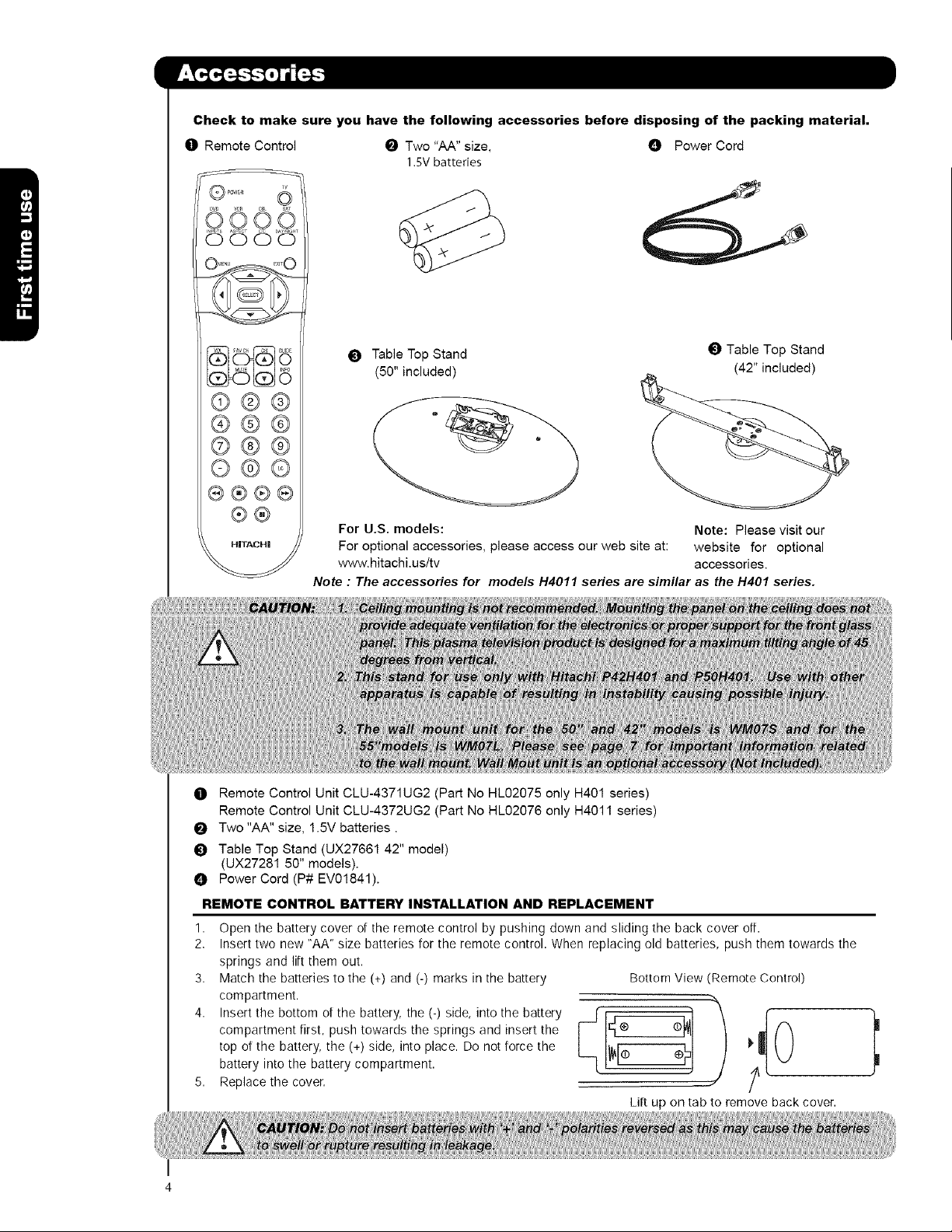
Checkto makesureyouhavethefollowingaccessoriesbeforedisposingofthepackingmaterial,
O Remote Control _ Two "AA" size, O Power Cord
1.SV batteries
©O Oo
0000
_) Table Top Stand
(50" included)
Table Top Stand
(42" included)
©@@
@@@
©@@
O@©
®®®®
®@
HITACHI
O Remote Control Unit CLU-4371UG2 (Part No HL02075 only H401 series)
Remote Control Unit CLU-4372UG2 (Part No HL02076 only H4011 series)
Two "AA" size, 1.5V batteries.
_) Table Top Stand (UX27661 42" model)
(UX27281 50" models).
O Power Cord (P# EV01841).
REMOTE CONTROL BATTERY INSTALLATION AND REPLACEMENT
1,
Open the battery cover of the remote control by pushing down and sliding the back cover off.
2,
Insert two new "AA" size batteries for the remote control. When replacing old batteries, push them towards the
springs and lift them out.
3.
Match the batteries to the (+) and (-) marks in the battery
compartment.
4.
compartment first, push towards the springs and insert the c_
top of the battery, the (+) side, into place. Do not force the
Insert the bottom of the battery, the (-) side, into the battery L-[I_r-_ F¢
battery into the battery compartment.
Replace the cover.
For U.S. models: Note: Please visit our
For optional accessories, please access our web site at: website for optional
www.hitachi.us/tv accessories.
Note : The accessories for models H4011 series are similar as the H401 series.
Bottom View (Remote Control)
Lilt up on tab to remove back cover.
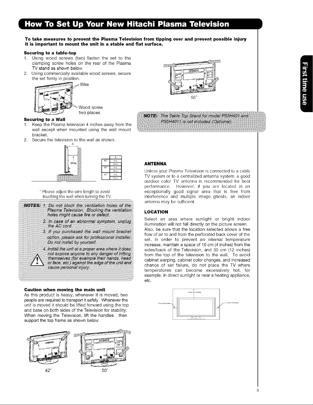
To take measures to prevent the Plasma Television from tipping over and prevent possible injury
it is important to mount the unit in a stable and flat surface.
Securing to a table-top
1. Using wood screws (two) fasten the set to the
clamping screw holes on the rear of the Plasma
TV stand as shown below.
2. Using commercially available wood screws, secure
the set firmly in position.
_W Wire
ood screw
wo places
Securing to a Wall
1. Keep the Plasma television 4 inches away from the
wall except when mounted using the wall mount
bracket.
2. Secure the television to the wall as shown.
A
ANTENNA
Unless your Plasma Television is connected to a cable
TV system or to a centralized antenna system, a good
outdoor color TV antenna is recommended for best
performance. However, if you are located in an
Please adjust the wire length to avoid
...................................................t°uch!ng !he wa!! wherl !u[ning !heTv .............................................
exceptionally good signal area that is free from
interference and multiple image ghosts, an indoor
antenna may be sufficient.
LOCATION
Select an area where sunlight or bright indoor
illumination will not fall directly on the picture screen.
Also, be sure that the location selected allows a free
flow of air to and from the perforated back cover of the
set. In order to prevent an internal temperature
increase, maintain a space of 10 cm (4 inches) from the
sides/back of the Television, and 30 cm (12 inches)
from the top of the television to the wall. To avoid
cabinet warping, cabinet color changes, and increased
chance of set failure, do not place the TV where
temperatures can become excessively hot, for
example, in direct sunlight or near a heating appliance,
etc.
55"
Caution when moving the main unit
As this product is heavy, whenever it is moved, two
people are required to transport it safely. Whenever the
unit is moved it should be lifted forward using the top
and base on both sides of the Television for stability.
When moving the Television, lift the handles , then
support the top frame as shown below.
42" 50"

AC CORD INSTALLATION INSTRUCTION
The AC cord provided with your new Plasma Television needs to be installed correctly
to avoid the AC cord from disconnecting when rotating the TV on its Table top stand.
Located on the back of the TV are 2 plastic clamps to hold the AC cord. Please follow the
instructions below.
O
Pass the AC cord through Clamp #1 and connect
it to the TV. Pull on the clamp to tighten the
AC cord to the TV.
O
The AC cord and the signal cables can all be
held together with Clamp #2.
O Depend on the model size 42",50" or 55", the
clamp may be different shapes. Only for 50" models
the clamp #2 will be included on the accessories
bag.
O Clamp #1 : Pass theAC cord through this clamp ;
then pull the clamp to tighten the AC
cord to the TV.
/
AC CORD
O Clamp #2: Use this clamp to hold the AC cord and
the signal cables. For 50 " model please
assemble this Clamp on the middle hole
of the base metal.
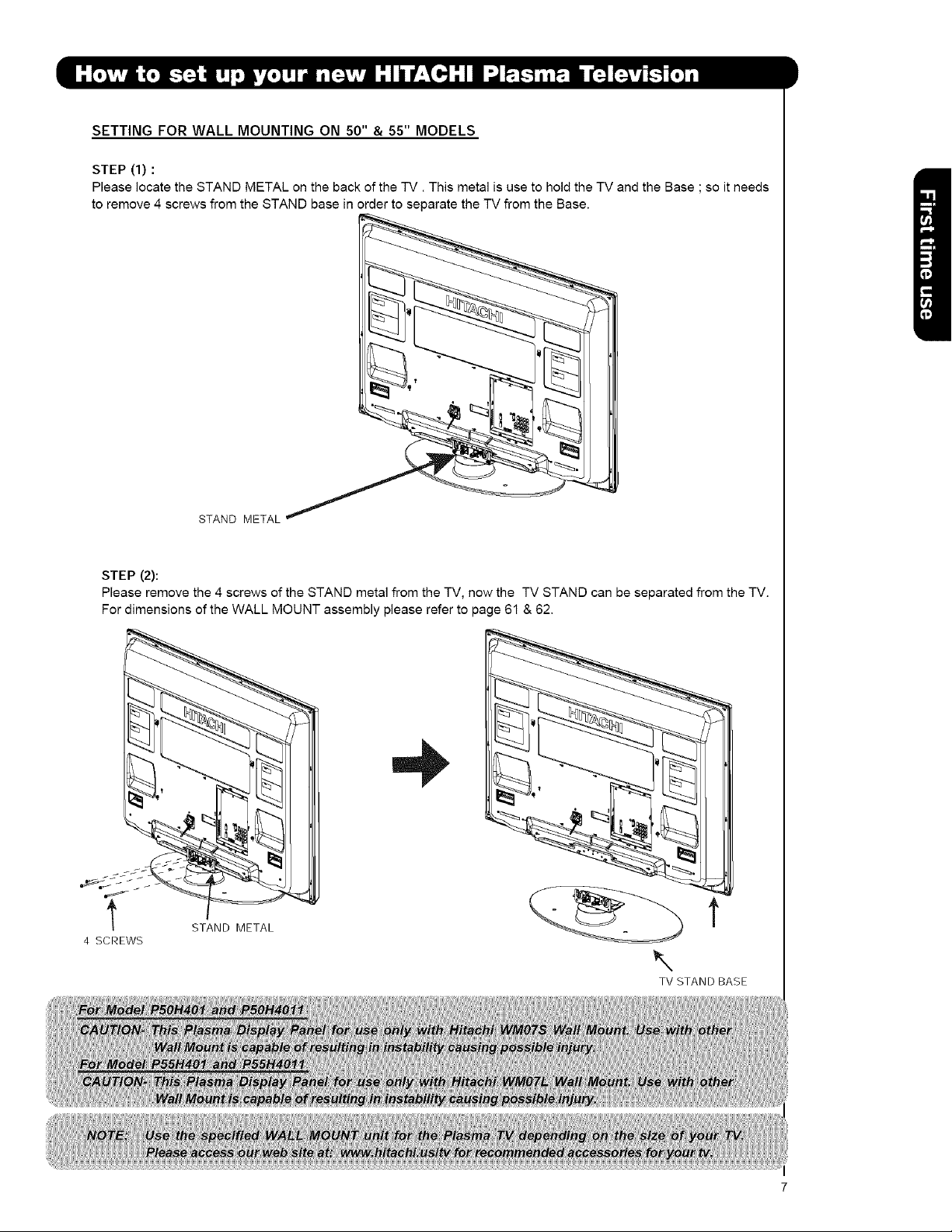
SETTING FOR WALL MOUNTING ON 50" & 55" MODELS
STEP (1) :
Please locate the STAND METAL on the back of the -iV. This metal is use to hold the TV and the Base ; so it needs
to remove 4 screws from the STAND base in order to separate the TV from the Base.
STAND METAL
STEP (2):
Please remove the 4 screws of the STAND metal from the TV, now the TV STAND can be separated from the TV.
For dimensions of the WALL MOUNT assembly please refer to page 61 & 62.
t STAND METAL
4 SCREWS
\
TV STAND BASE
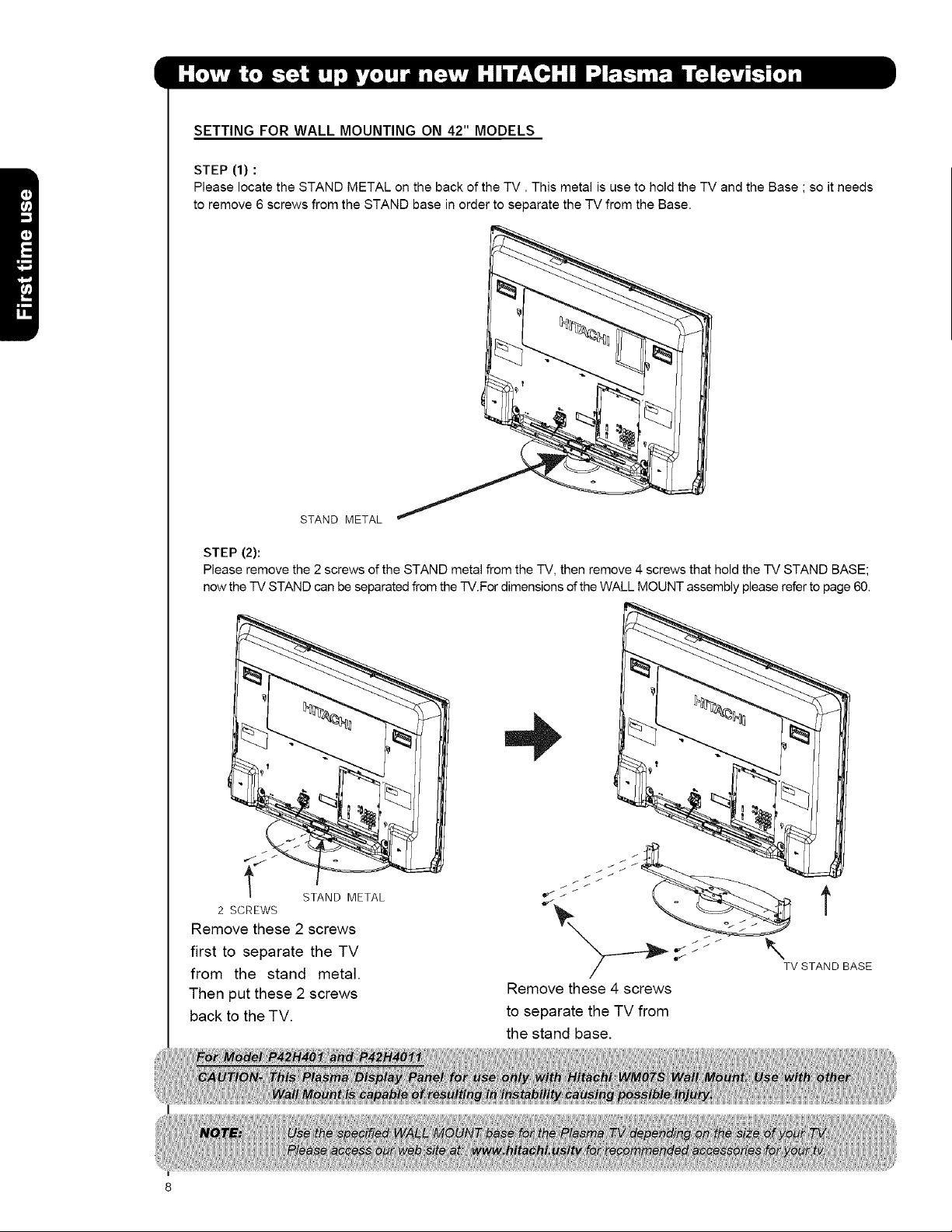
SETTING FOR WALL MOUNTING ON 42" MODELS
STEP (1) :
Please locate the STAND METAL on the back of the TV. This metal is use to hold the TV and the Base ; so it needs
to remove 6 screws from the STAND base in order to separate the TV from the Base.
STAND METAL
STEP (2):
Please remove the2 screws ofthe STAND metal from the -iV,then remove 4 screws thatholdthe IV STAND BASE;
now theIV STAND can be separatedfrom the-iV.FordimensionsoftheWALL MOUNT assembly pleasereferto page 60.
2 SCREWS
STAND METAL
Remove these 2 screws
first to separate the TV
from the stand metal.
Then put these 2 screws
back to the TV.
t
SSSSS_
TV STAND BASE
Remove these 4 screws
to separate the TV from
the stand base.
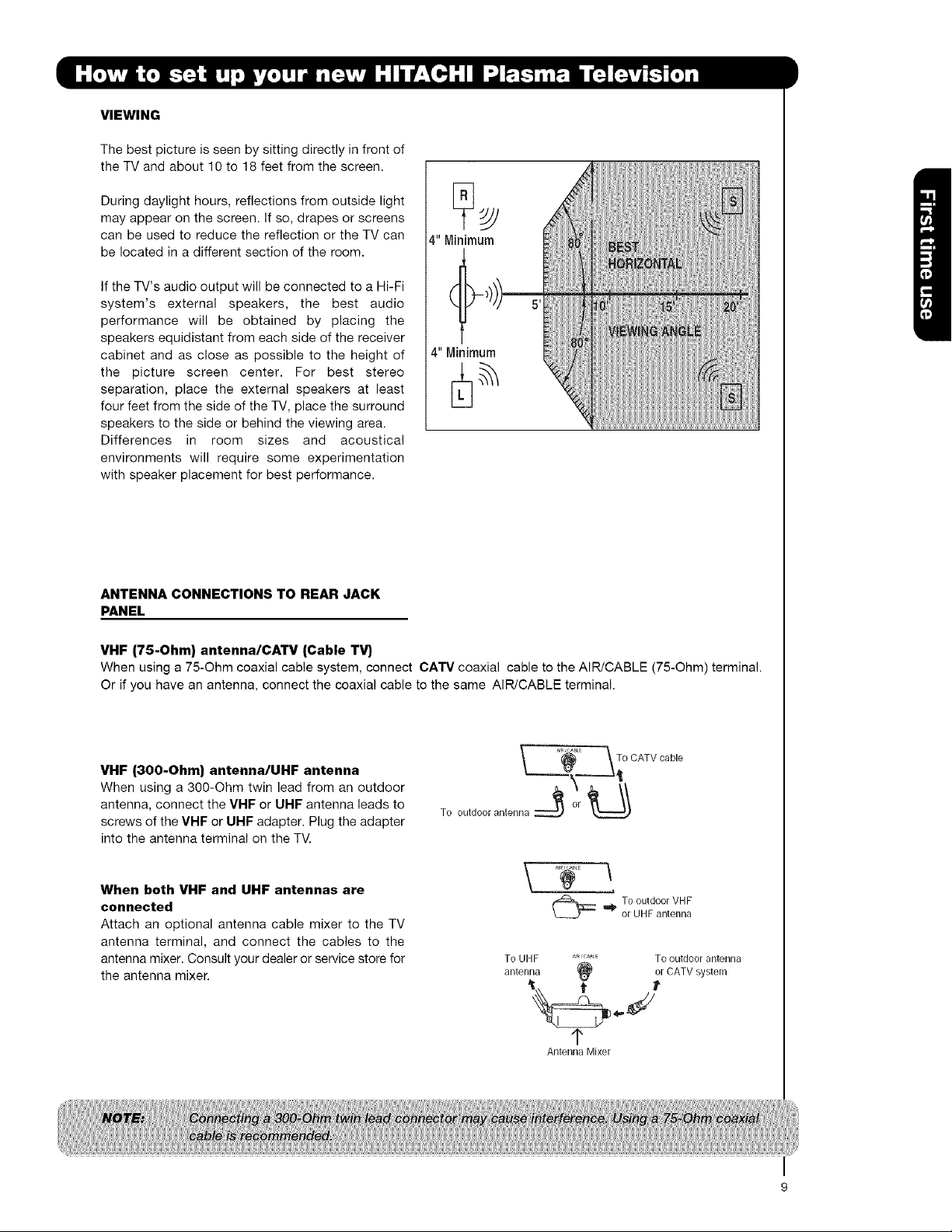
VIEWING
The best picture is seen by sitting directly in front of
the TV and about 10 to 18 feet from the screen.
During daylight hours, reflections from outside light
may appear on the screen. If so, drapes or screens
can be used to reduce the reflection or the TV can
be located in a different section of the room.
If the TV's audio output will be connected to a Hi-Fi
system's external speakers, the best audio
performance will be obtained by placing the
speakers equidistant from each side of the receiver
cabinet and as close as possible to the height of
the picture screen center. For best stereo
separation, place the external speakers at least
four feet from the side of the TV, place the surround
speakers to the side or behind the viewing area.
Differences in room sizes and acoustical
environments will require some experimentation
with speaker placement for best performance.
4" Minimum
4" Minimum
ANTENNA CONNECTIONS TO REAR JACK
PANEL
VHF (75-Ohm) antenna/CA33# (Cable T_
When using a 75-Ohm coaxial cable system, connect CA'IV coaxial cable to the AIR/CABLE (75-Ohm) terminal.
Or if you have an antenna, connect the coaxial cable to the same AIR/CABLE terminal.
VHF (300-Ohm) antenna/UHF antenna
When using a 300-Ohm twin lead from an outdoor
antenna, connect the VHF or UHF antenna leads to
screws of the VHF or UHF adapter. Plug the adapter
into the antenna terminal on the TV.
When both VHF and UHF antennas are
connected
Attach an optional antenna cable mixer to the TV
antenna terminal, and connect the cables to the
antenna mixer. Consult your dealer or service store for
the antenna mixer.
_. _, :_L_ _ To
To outdoor antenna :::_ '_°r _
To UHF AIR'GABLE TO outdoor antenna
antenna (_ or CATV system
OATvoab,e
TooutdoorVHF
or UHFantenna
1"
Antenna Mixer
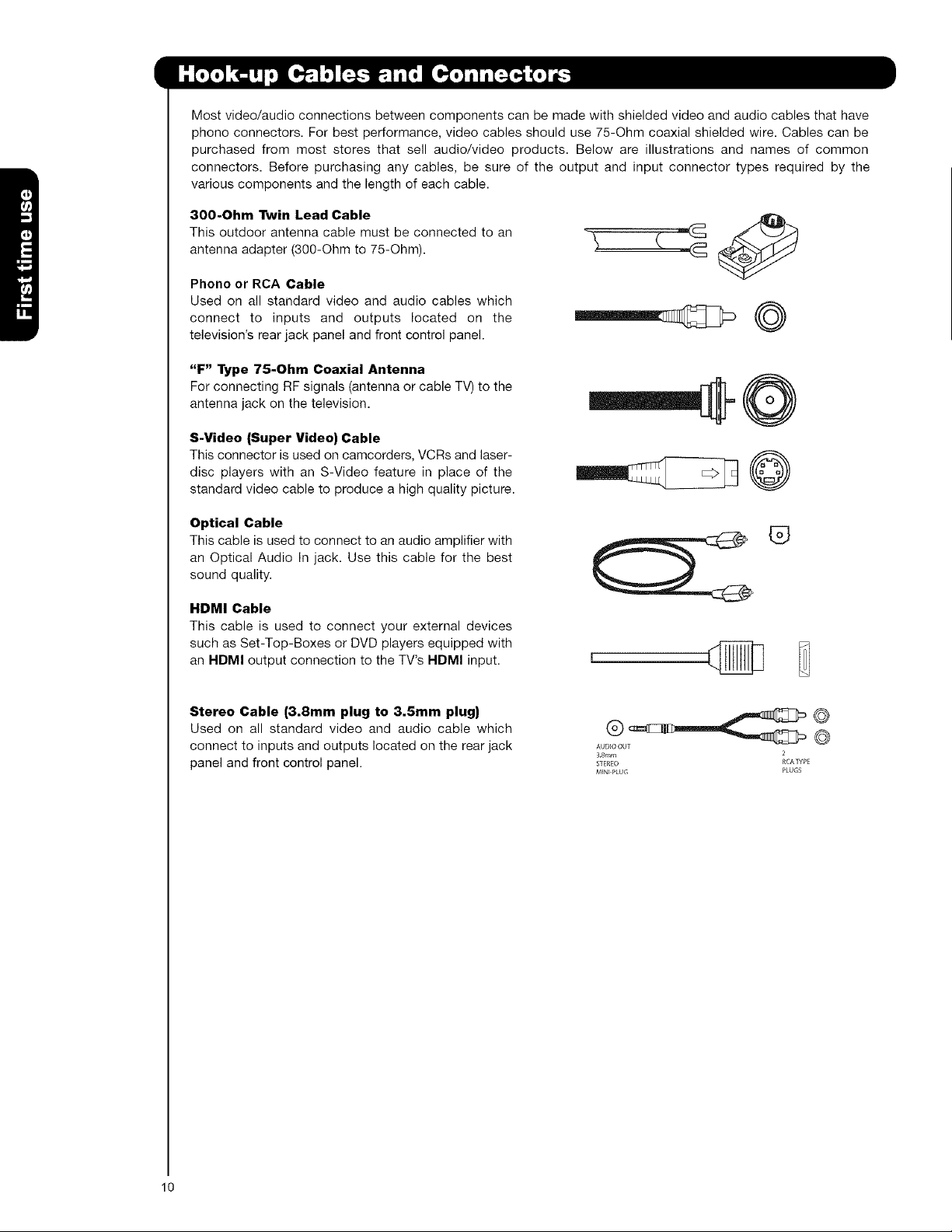
Most video/audio connections between components can be made with shielded video and audio cables that have
phone connectors. For best performance, video cables should use 75-Ohm coaxial shielded wire. Cables can be
purchased from most stores that sell audio/video products. Below are illustrations and names of common
connectors. Before purchasing any cables, be sure of the output and input connector types required by the
various components and the length of each cable.
300-Ohm Twin Lead Cable
This outdoor antenna cable must be connected to an
antenna adapter (300-Ohm to 75-Ohm).
Phone or RCA Cable
Used on all standard video and audio cables which
connect to inputs and outputs located on the
television's rear jack panel and front control panel.
"F" Type 75-Ohm Coaxial Antenna
For connecting RF signals (antenna or cable TV) to the
antenna jack on the television.
S-Video (Super Video) Cable
This connector is used on camcorders, VCRs and laser-
disc players with an S-Video feature in place of the
standard video cable to produce a high quality picture.
©
Optical Cable
This cable is used to connect to an audio amplifier with
an Optical Audio In jack. Use this cable for the best
sound quality.
HDMI Cable
This cable is used to connect your external devices
such as Set-Top-Boxes or DVD players equipped with
an HDMI output connection to the TV's HDMI input.
Stereo Cable (3.8mm plug to 3.5mm plug)
Used on all standard video and audio cable which
connect to inputs and outputs located on the rear jack
panel and front control panel.
®
AUD_OOUT {_
38ram
STEREO
MINt PLUG PLUGS
10

InadditiontocontrollingallofthefunctionsonyourHITACHIPlasmaTV,thenewremotecontrolis
designedtooperatedifferenttypesofdevices,suchas,DVDPlayers,CBL(CableBoxes),set-top-boxes,satellite
receivers,andVCRs.Theremotecontrolmustbeprogrammedtocontrolthechosendevice.Pleaseseepages23-
31foracompletedescriptionofallfeaturesandprogrammingoftheRemoteControl.
(TV,CBL,VCR,DVD,SAT}".
POWERBUTTON
Turnstheselecteddeviceon
andoff.
INPUTSBUTTON
AccessestheINPUTSmenu
system.
ASPECTBUTTON
Changestheaspectratiowhile
watchingTV.
MENU
(CBL, DVD, SAT, TV} '
Accesses the OSD menu
system. ,_
CURSOR/SELECT BUTTONS --"f,
(TV, DVD, CBL, SAT}
SOURCE ACCESS BUTTONS
(TV, DVD, VCR, CBL, SAT}
POWER
INPUTS
i[
ASPECT
Changes the mode of the
Universal Remote Control to
control the device selected.
BUTTON (TV}
Select picture mode settings
between DAY and NIGHT mode.
BUTTON (TV)
Press to show and change the
Closed Caption mode.
BUTTON
(TV, CBL, SAT}
Exits out of the OSD or INPUTS
menu systems if their menu is
displayed.
entry when navigating through
the OSD menu system.
(-} BUTTON (TV, SAT}
The (-) button is used when the
remote is in Set-Top-Box (STB)
mode or when the TV uses a
digital input.
RECORD BUTTON (VCR}
Press twice (2 times) to record
programs.
LEGEND
"13/-- Television
CBL- Cable Box
VCR-- Video Cassette Recorder/Player SATi Satellite Receiver
DVD- Digital Video Disc Player
HITACHI
i and last channel viewed.
i
i
i
DVD/VCR CONTROL
BUTTONS (DVD, VCR}
Controls the preeode functions
of your VCR and DVD.
i"
11
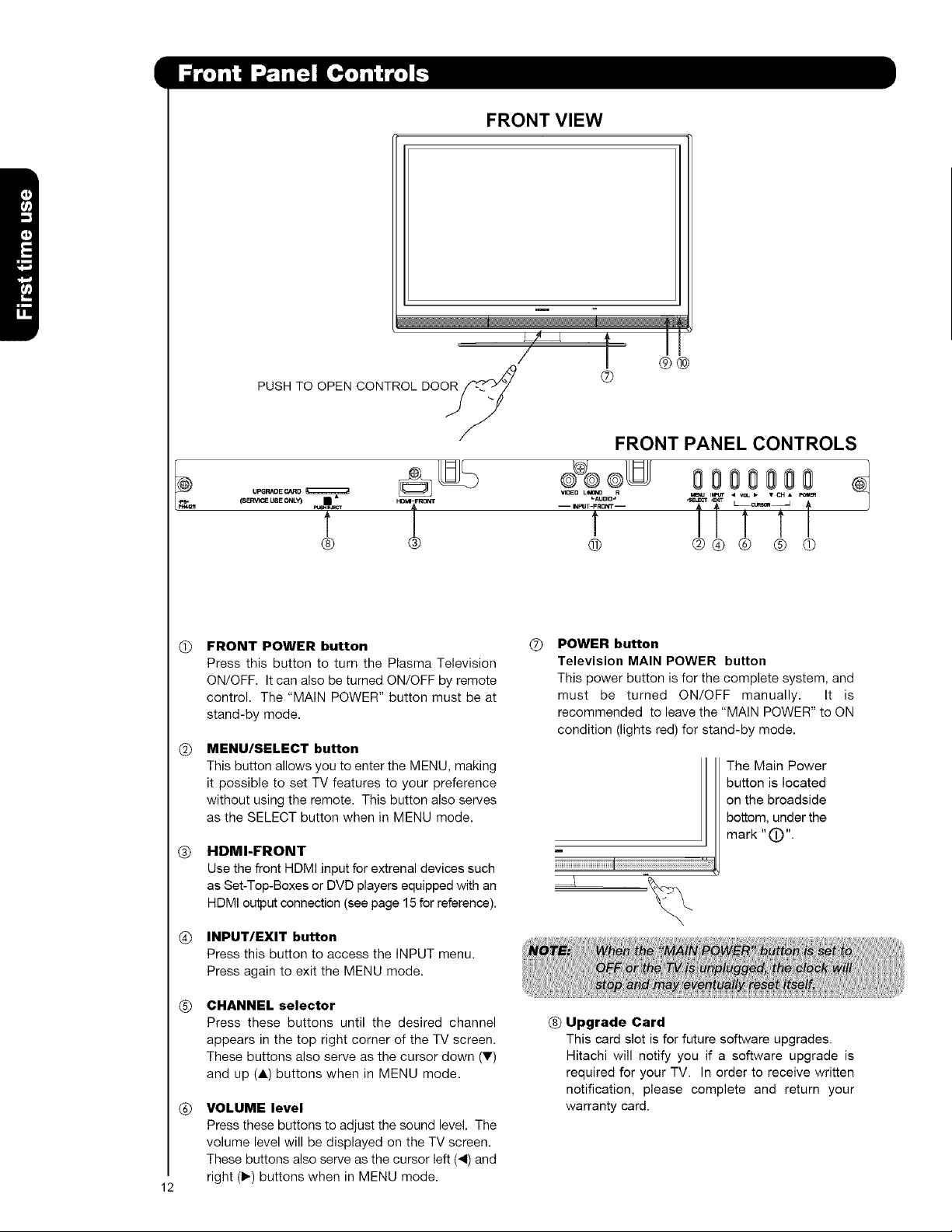
FRONT VIEW
m
/ j ®®
PUSH TO OPEN CONTROL DOOR_/'_i ®
JY
/
FRONT PANEL CONTROLS
@
(s_ca useONLY) • *
t
@ _i °°_
FRONT POWER button
@
Press this button to turn the Plasma Television
ON/OFF. It can also be turned ON/OFF by remote
control. The "MAIN POWER" button must be at
stand-by mode.
MENU/SELECT button
@
This button allows you to enter the MENU, making
it possible to set TV features to your preference
without using the remote. This button also serves
as the SELECT button when in MENU mode.
HDMI.FRONT
®
Use the front HDMI input for extrenal devices such
as Set-Top-Boxes or DVD players equipped with an
HDMI output connection (see page 15 for reference).
INPUT/EXIT button
®
Press this button to access the INPUT menu.
Press again to exit the MENU mode.
-- I_PUT-FRONT -- _C_ _
...... it .........f
f T T
® @® @ @ @
POWER button
®
Television MAIN POWER button
This power button is for the complete system, and
must be turned ON/OFF manually. It is
recommended to leave the "MAIN POWER" to ON
condition (lights red) for stand-by mode.
The Main Power
button is located
on the broadside
bottom, under the
m
mark "(D".
CHANNEL selector
®
Press these buttons until the desired channel
appears in the top right corner of the TV screen.
These buttons also serve as the cursor clown (V)
and up (A) buttons when in MENU mode.
VOLUME level
®
Press these buttons to adjust the sound level. The
volume level will be displayed on the TV screen.
These buttons also serve as the cursor left (4) and
right (1_)buttons when in MENU mode.
12
® Upgrade Card
This card slot is for future software upgrades.
Hitachi will notify you if a software upgrade is
required for your TV. In order to receive written
notification, please complete and return your
warranty card.
®
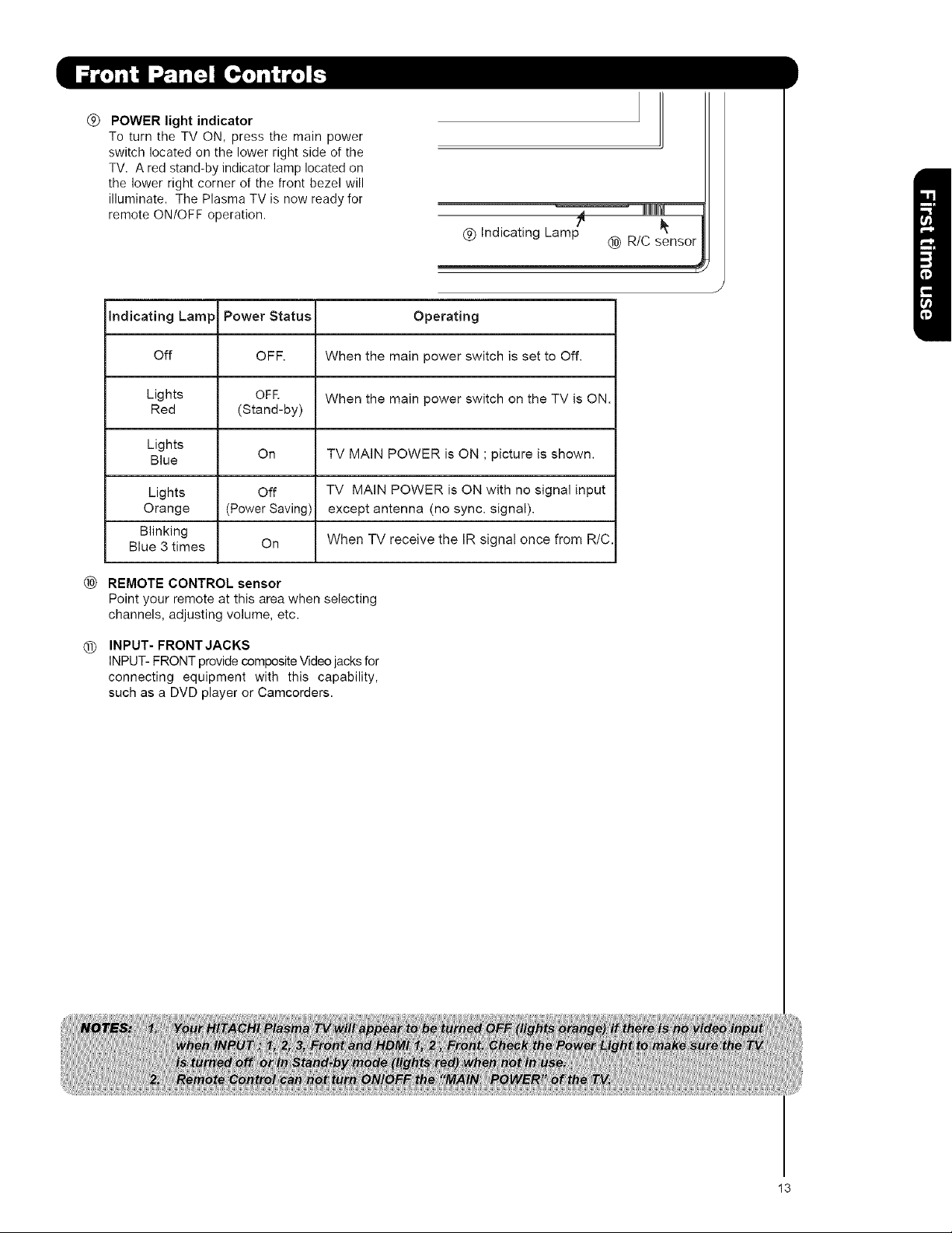
POWER light indicator
To turn the TV ON, press the main power
switch located on the lower right side of the
TV. A red stand-by indicator lamp located on
the lower right corner of the front bezel will
illuminate. The Plasma TV is now ready for
remote ON/OFF operation.
(_) Indicating Lamp
Indicating Lamp Power Status Operating
Off OFF. When the main power switch is set to Off.
Lights OFR When the main power switch on the TV is ON.
Red (Stand-by)
Lights
Blue On TV MAIN POWER is ON ; picture is shown.
Lights Off TV MAIN POWER is ON with no signal input
Orange (Power Saving) except antenna (no sync. signal).
Blinking
Blue 3 times On When TV receive the IR signal once from R/C.
® R/C sensor
i
®
REMOTE CONTROL sensor
Point your remote at this area when selecting
channels, adjusting volume, etc.
INPUT- FRONT JACKS
®
INPUT- FRONT provide composite Video jacks for
connecting equipment with this capability,
such as a DVD player or Camcorders.
13
@
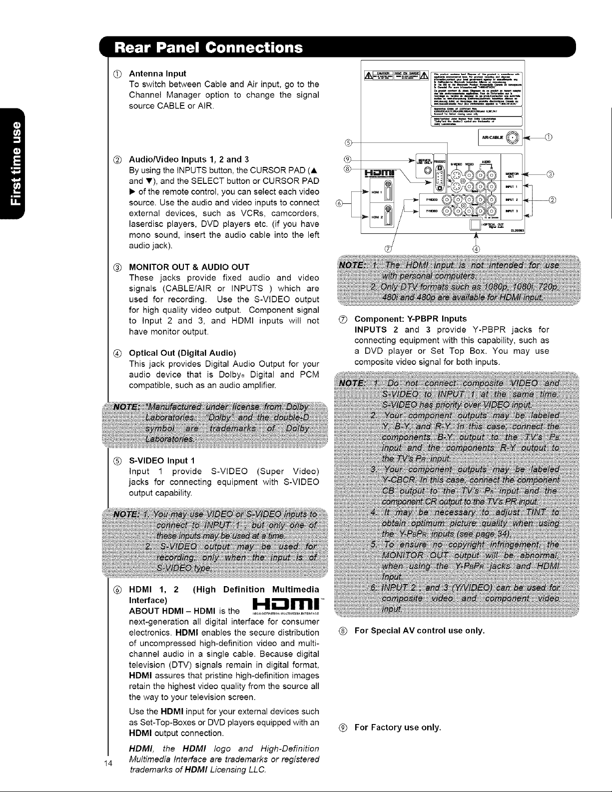
Antenna Input
To switch between Cable and Air input, go to the
Channel Manager option to change the signal
source CABLE or ALP,.
@
Audio/Video Inputs 1, 2 and 3
By using the INPUTS button, the CURSOR PAD (A
and T), and the SELECT button or CURSOR PAD
1_of the remote control, you can select each video
source. Use the audio and video inputs to connect
external devices, such as VCRs, camcorders,
laserdisc players, DVD players etc. (if you have
mono sound, insert the audio cable into the left
audio jack).
MONITOR OUT & AUDIO OUT
®
These jacks provide fixed audio and video
signals (CABLE/AIR or INPUTS ) which are
used for recording. Use the S-VIDEO output
for high quality video output. Component signal
to Input 2 and 3, and HDMI inputs will not
have monitor output.
@
Optical Out (Digital Audio)
This jack provides Digital Audio Output for your
audio device that is Dolby,_ Digital and PCM
compatible, such as an audio amplifier.
@
[.....®
®
@
® Component: Y-PBPR Inputs
INPUTS 2 and 3 provide Y-PBPR jacks for
connecting equipment with this capability, such as
a DVD player or Set Top Box. You may use
composite video signal for both inputs.
® S-VIDEO Input 1
Input 1 provide S-VIDEO (Super Video)
jacks for connecting equipment with S-VIDEO
I
output capability.
®
HDMI 1, 2 (High Definition Multimedia
Interface) H.- ml=
ABOUT HDMI - HDMI is the .....................................
next-generation all digital interface for consumer
electronics. HDMI enables the secure distribution
of uncompressed high-definition video and multi-
channel audio in a single cable. Because digital
television (DTV) signals remain in digital format,
HDMI assures that pristine high-definition images
retain the highest video quality from the source all
the way to your television screen.
Use the HDMI input for your external devices such
as Set-Top-Boxes or DVD players equipped with an
HDMI output connection.
HDMI, the HDMI logo and High-Definition
Multimedia Interface are trademarks or registered
14
trademarks of HDMI Licensing LLC.
® For Special AV control use only.
(_ For Factory use only.
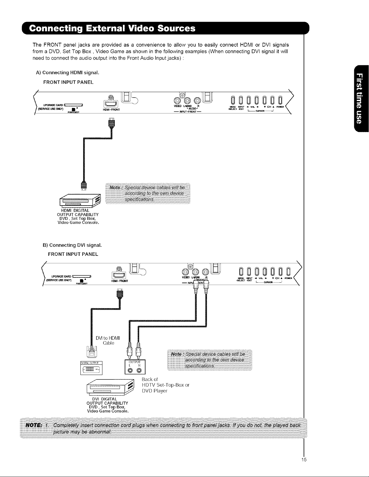
TheFRONTpaneljacksareprovidedasaconveniencetoallowyoutoeasilyconnectHDMIorDVIsignals
fromaDVD,SetTopBox,VideoGameasshowninthefollowingexamples(WhenconnectingDVlsignalitwill
needtoconnecttheaudiooutputintotheFrontAudioInputjacks):
A)ConnectingHDMIsignal.
FRONTINPUTPANEL
v,o.o®
HDMI DIGITAL
OUTPUTCAPABILITY
DVD, Set Top Box,
Video Game Console.
HDMI_FRON T L AUDIO=
L/MONO R
-- INPUT-FRONT-
_Nu INPUT C A
,SELECT _E_T L _SOR3
B) Connecting DVI signal.
FRONT INPUT PANEL
_(( UPGRADE CARD
SERVICE USE ONLY) • • HDI_II-FRONT
DVIto HDMI
Cable
DVi DIGITAL
OUTPUTCAPABILITY
DVD, Set Top Box,
Video Game Console.
Back ot
VIDEO _0
-- INP _
MENU INPUT C R
,sa_cT ,Exrr LCU_SOR_
15
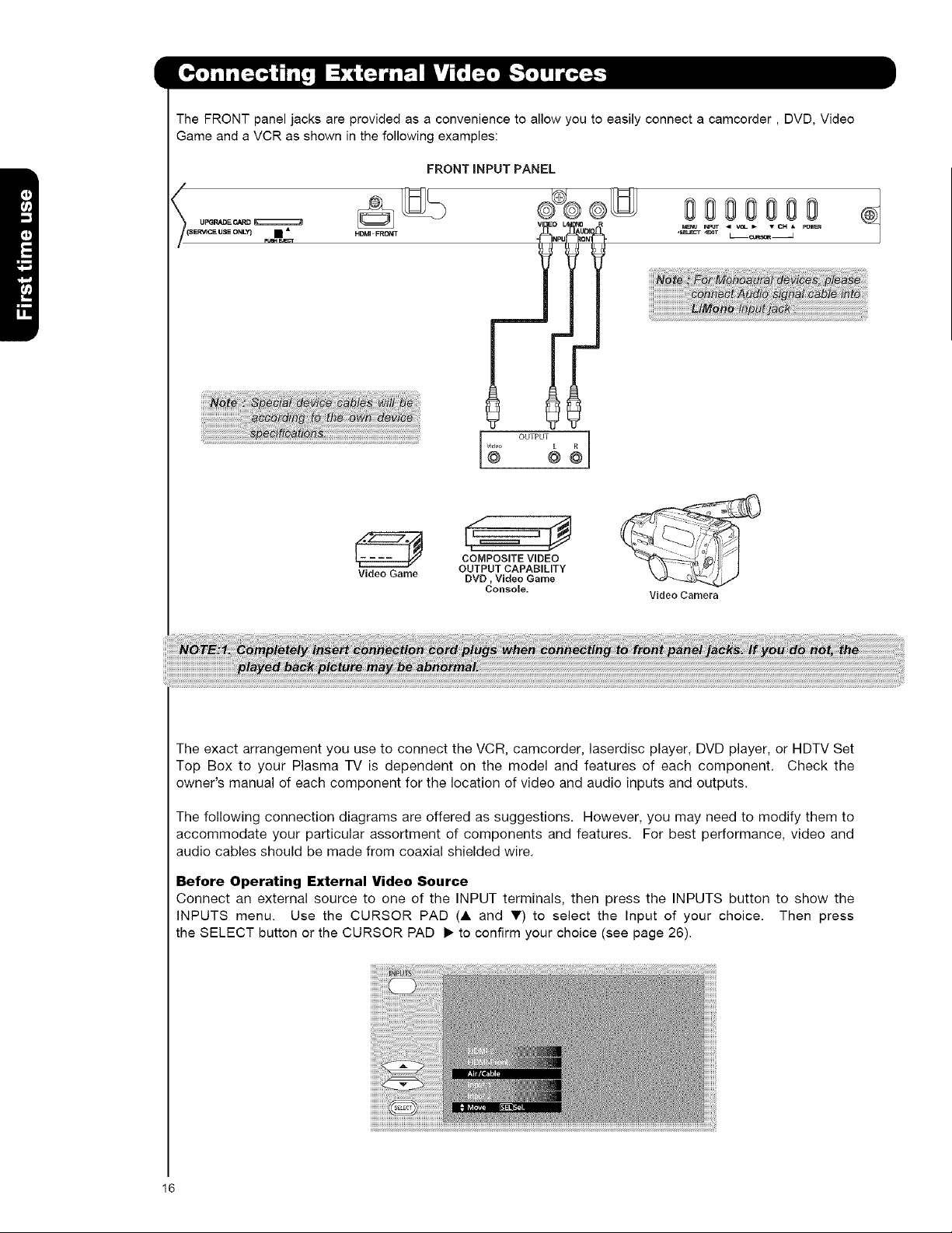
TheFRONTpaneljacksareprovidedasaconveniencetoallowyoutoeasilyconnectacamcorder,DVD,Video
GameandaVCRasshowninthefollowingexamples:
FRONTINPUTPANEL
/
000 00
UF_RADE CARD
(SERVICE USE ONLY} • •
N=UT < VOL _ • CH • PO_
,S_cr _T L_CO_S_ _
f
OUTPUT I
Video Game OUTPUT CAPABILITY
The exact arrangement you use to connect the VCR, camcorder, laserdisc player, DVD player, or HDTV Set
Top Box to your Plasma TV is dependent on the model and features of each component. Check the
owner's manual of each component for the location of video and audio inputs and outputs.
The following connection diagrams are offered as suggestions. However, you may need to modify them to
accommodate your particular assortment of components and features. For best performance, video and
audio cables should be made from coaxial shielded wire.
Before Operating External Video Source
Connect an external source to one of the INPUT terminals, then press the INPUTS button to show the
INPUTS menu. Use the CURSOR PAD (A and V) to select the Input of your choice. Then press
the SELECT button or the CURSOR PAD 1_to confirm your choice (see page 26).
COMPOSITE VIDEO
DVD, Video Game
Console.
Video Camera
16
Outside Anten_sa
Cable TVroaxial cable
Optional
VCR#2
@oQ@
s VIDEOVINpLT R
VCR#1
OUTPUT
ANNT SVIDEOV L
@ @ooo
oon
d_ I_i_ _i_r_ _p_=bl_ Pour _ nr,r_ti_ _ur I_
_k_y-_d th_ d_ubt,_l _yr_,d _ tr_J_mr_ of
m J
HDMI
HDMI DIGITAL
OUTPUT CAI ABILITY
HDMI
to
H:-.mm| TM
@/
HDMII III III
r@/
HDMI 2 III III
HDMI
DIGITAL DVD Player
OUTPUT CAI ABILITY
)
/ \
HDTV SebTop Box
17
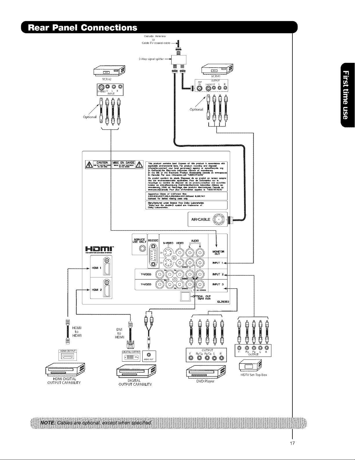
• S-VIDEO, Y-PBPR, or HDMI connections are provided for high performance laserdisc players, VCRs etc. that
have this feature. Use these connections in place of the standard video connection if your device has this
feature.
• If your device has only one audio output (mono sound), connect it to the left audio jack on (L/(MONO)) the
Rear Panel.
• Refer to the operating guide of your other electronic equipment for additional information on connecting
your hook-up cables.
• A single VCR can be used for VCR #1 and VCR #2, but note that a VCR cannot record its own video or line
output (INPUT: 1 in the example on page 17). Refer to your VCR operating guide for more information on
line input-output connections.
• Connect only 1 component (VCR, DVD player, camcorder, etc.) to each input jack.
• COMPONENT: Y-PBPR (Input 2 & 3) connections are provided for high performance components, such as
DVD players and set-top-boxes. Use these connections in place of the standard video connection if your
device has this feature.
• Your component outputs may be labeled Y, B-Y, and R-Y. In this case, connect the components B-Y
output to the TV's PB input and the components R-Y output to the TV's PR input.
• Your component outputs may be labeled Y-CBC R. In this case, connect the components C B output to the
TV's PB input and the components CR output to the TV's PR input.
• It may be necessary to adjust TINT to obtain optimum picture quality when using the Y-PBPR inputs. (See
page 34)
• To ensure no copyright infringement, the MONITOR OUT output will be abnormal, when using the Y-PBPR and
HDMI input jacks.
• Input HDMI 1, HDMI 2 or HDMI FRONT can accept HDMI signal.
• S-VIDEO monitor output may be used for recording only when the input is of S-VIDEO type.
• When using a HDMI input from a Set-Top-Box, it is recommended to use a 1080p, 1080i or 720p input signal.
• When HDMI input a 1080p signal, the length of the cable should be less than 5 meters.
18
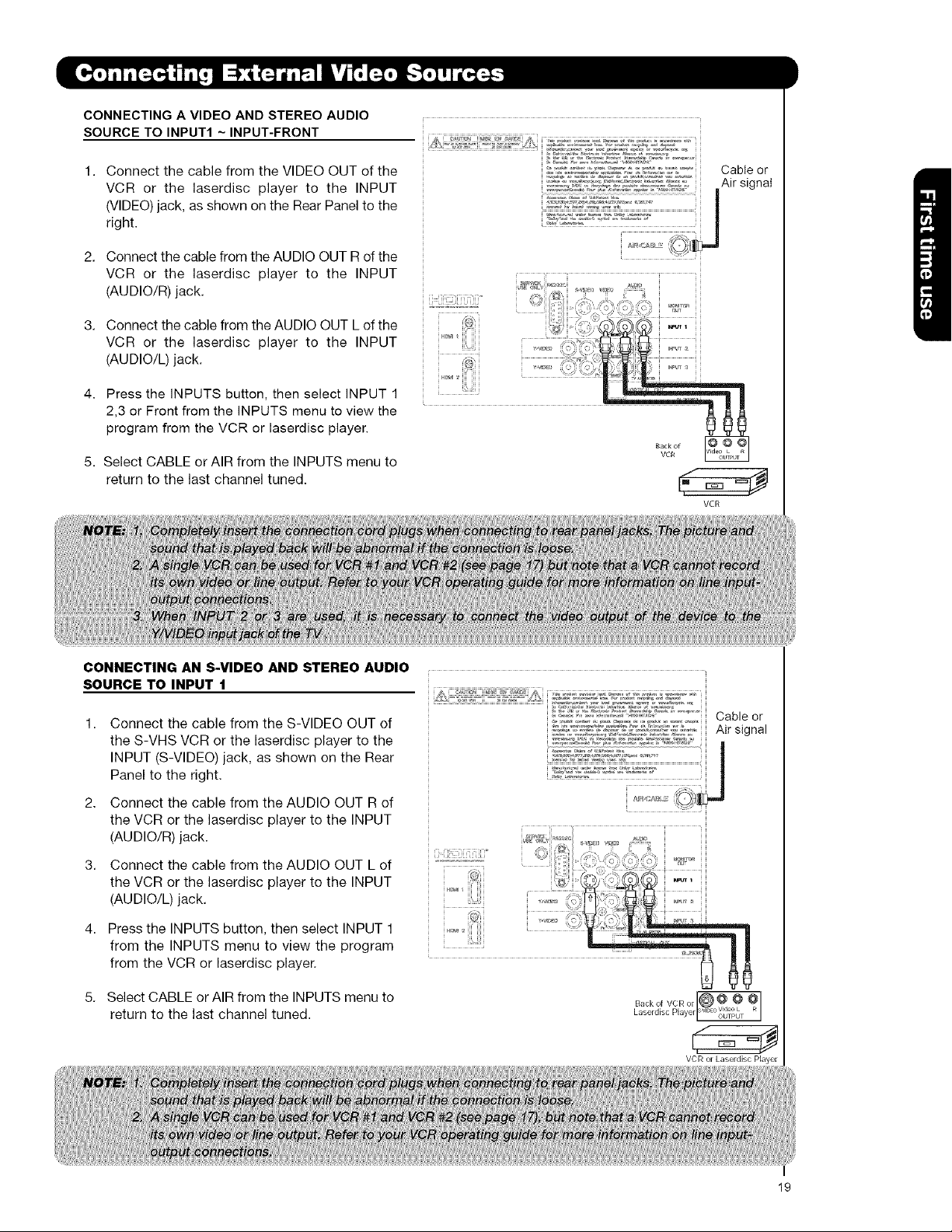
CONNECTINGA VIDEO AND STEREO AUDIO
SOURCE TO INPUT1 ~ INPUT-FRONT
1. Connect the cable from the VIDEO OUT of the
VCR or the laserdisc player to the INPUT
(VIDEO) jack, as shown on the Rear Panel to the
right.
2. Connect the cable from the AUDIO OUT R of the
VCR or the laserdisc player to the INPUT
(AUDIO/R) jack.
3. Connect the cable from the AUDIO OUT L of the
VCR or the laserdisc player to the INPUT
(AUDIO/L) jack.
4. Press the INPUTS button, then select INPUT 1
2,3 or Front from the INPUTS menu to view the
program from the VCR or laserdisc player.
5. Select CABLE or AIR from the INPUTS menu to
return to the last channel tuned.
VCR
CONNECTING AN S-VIDEO AND STEREO AUDIO
SOURCE TO INPUT 1
Connect the cable from the S-VIDEO OUT of
the S-VHS VCR or the laserdisc player to the
INPUT (S-VIDEO) jack, as shown on the Rear
Panel to the right.
2. Connect the cable from the AUDIO OUT R of
the VCR or the laserdisc player to the INPUT
(AUDIO/R) jack.
3. Connect the cable from the AUDIO OUT L of
the VCR or the laserdisc player to the INPUT
(AUDIO/L) jack.
4. Press the INPUTS button, then select INPUT 1
from the INPUTS menu to view the program
from the VCR or laserdisc player.
5. Select CABLE or AIR from the INPUTS menu to
return to the last channel tuned.
Cable or
Air signal
Backof VCRor @ V@d_,e_L
Laserd sc Payer[svD °OUTPUT
VCR or kaserdisc Player
19
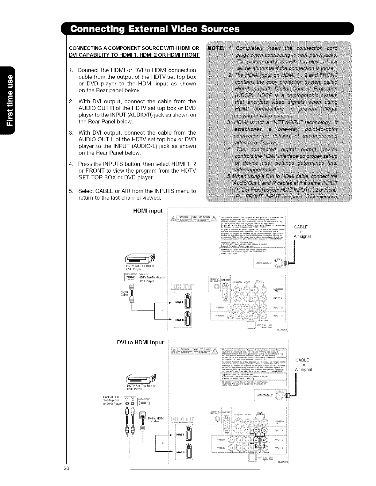
CONNECTING A COMPONENT SOURCE WITH HDMI OR
DVI CAPABILITY TO HDMI I r HDMI 2 OR HDMI FRONT
Connect the HDMI or DVI to HDMI connection
cable from the output of the HDTV set top box
or DVD player to the HDMI input as shown
on the Rear panel below.
2,
With DVl output, connect the cable from the
AUDIO OUT R of the HDTV set top box or DVD
player to the INPUT (AUDIO/R) jack as shown on
the Rear Panel below.
3,
With DVl output, connect the cable from the
AUDIO OUT L of the HDTV set top box or DVD
player to the INPUT (AUDIO/L) jack as shown
on the Rear Panel below.
4,
Press the INPUTS button, then select HDMI 1, 2
or FRONT to view the program from the HDTV
SET TOP BOX or DVD player.
5.
Select CABLE or AIR from the INPUTS menu to
return to the last channel viewed.
HDMI input
HDTV Set-Top Box or
DVD Player
DVI to HDMI Input
HDTV Set Top Box or
DVD Player
Set Top Box
or DVD Player
CABLE
or
Air signal
[i iJi!!!Ci[i[iii[i°
j !t'
' " "°" ............................ CABLE
.._-°_','- ,-,,,<_.-,.'._._. ,-o-o, Air sinnal
2O
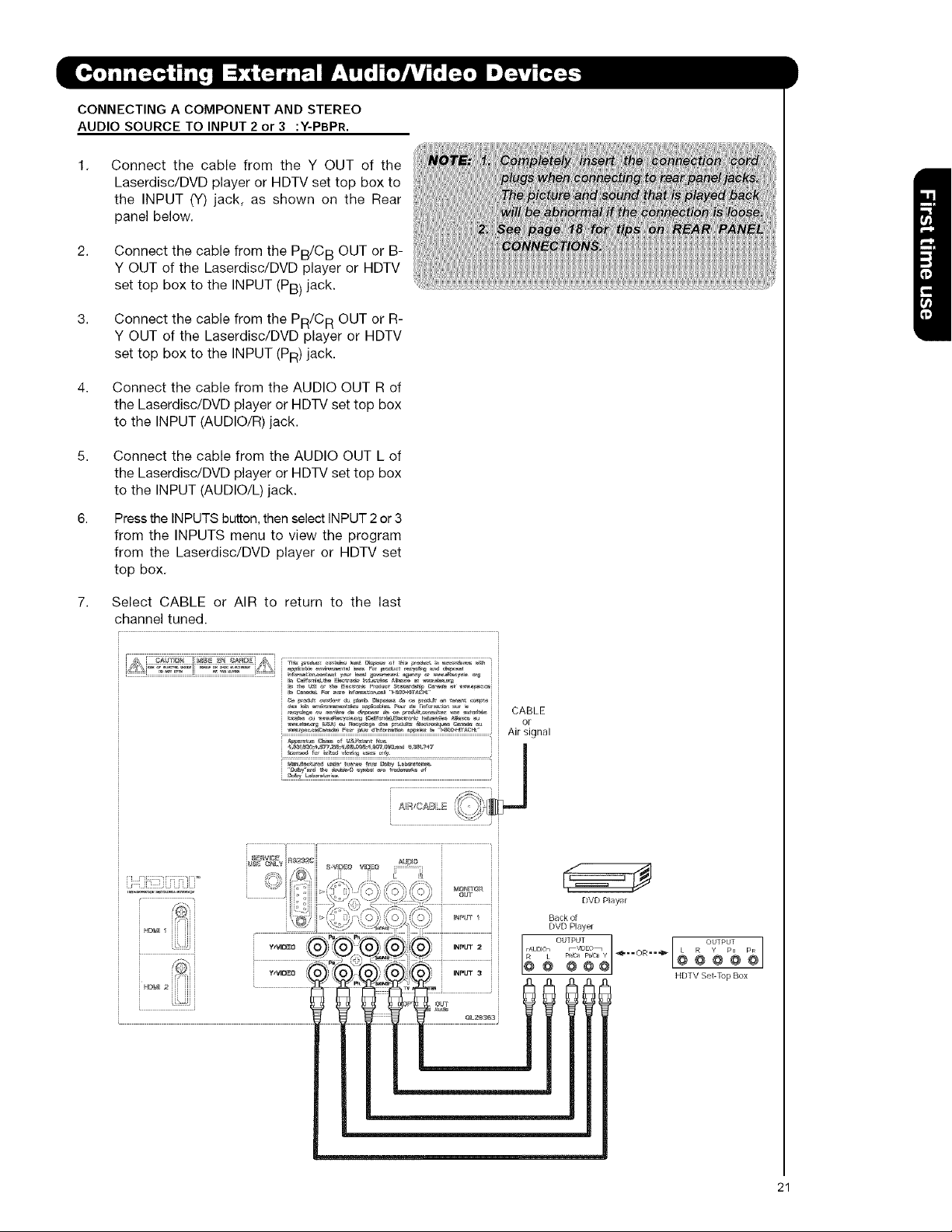
CONNECTING A COMPONENT AND STEREO
AUDIO SOURCE TO INPUT 2 or 3 :Y-PBPR.
1.
Connect the cable from the Y OUT of the
Laserdisc/DVD player or HDTV set top box to
the INPUT (Y) jack, as shown on the Rear
panel below.
2.
Connect the cable from the PB/CB OUT or B-
Y OUT of the Laserdisc/DVD player or HDTV
set top box to the INPUT (PB) jack.
3.
Connect the cable from the PR/CR OUT or R-
Y OUT of the Laserdisc/DVD player or HDTV
set top box to the INPUT (PR) jack.
4.
Connect the cable from the AUDIO OUT R of
the Laserdisc/DVD player or HDTV set top box
to the INPUT (AUDIO/R) jack.
5,
Connect the cable from the AUDIO OUT L of
the Laserdisc/DVD player or HDTV set top box
to the INPUT (AUDIO/L) jack.
6.
Pressthe INPUTS button, then select INPUT 2 or 3
from the INPUTS menu to view the program
from the Laserdisc/DVD player or HDTV set
top box.
7,
Select CABLE or AIR to return to the last
channel tuned.
[ i[ i[ [ i J
u_¢: @NLY • • ,. AU[_IO
" "_,h fzvlE_:o vl[l'_o :::::::_::::::::
_,_[;e_iI . ...................2J ::::: _ ?) [: : 1 J
/ X_b/_ ," -_" DVD Paye
WVIB_O 0 }J):X_ )_ ,)){_O)/_) INPUT a HDTVSeI-TupBox
I
@ @ @ @ @
I
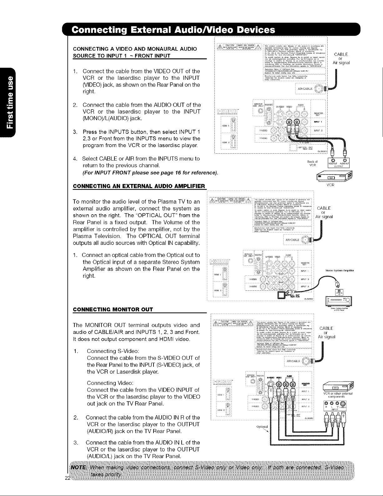
CONNECTING A VIDEO AND MONAURAL AUDIO
SOURCE TO INPUT 1 ~ FRONT INPUT
1. Connect the cable from the VIDEO OUT of the
VCR or the laserdisc player to the INPUT
(VIDEO) jack, as shown on the Rear Panel on the
right.
2.
Connect the cable from the AUDIO OUT of the
VCR or the laserdisc player to the INPUT
(MONO)/L(AUDIO) jack. ,
3.
Press the INPUTS button, then select INPUT 1
2,3 or Front from the INPUTS menu to view the
program from the VCR or the laserdisc player.
4. Select CABLE or AIR from the INPUTS menu to
return to the previous channel.
(For INPUT FRONT please see page 16 for reference).
CABLE
or
Air signal
i
CONNECTING AN EXTERNAL AUDIO AMPLIFIER
To monitor the audio level of the Plasma TV to an
external audio amplifier, connect the system as
shown on the right. The "OPTICAL OUT" from the
Rear Panel is a fixed output. The Volume of the
amplifier is controlled by the amplifier, not by the
Plasma Television. The OPTICAL OUT terminal
outputs all audio sources with Optical IN capability.
1. Connect an optical cable from the Optical out to
the Optical input of a separate Stereo System
Amplifier as shown on the Rear Panel on the
right.
CONNECTING MONITOR OUT
The MONITOR OUT terminal outputs video and
audio of CABLE/AIR and INPUTS 1, 2, 3 and Front.
It does not output component and HDMI video.
Connecting S-Video:
Connect the cable from the S-VIDEO OUT of
the Rear Panel to the INPUT (S-VIDEO) jack, of
the VCR or Laserdisk player.
CABLE
o[
Air signal
VCR
Connecting Video:
Connect the cable from the VIDEO INPUT of
the VCR or the laserdisc player to the VIDEO
out jack on the TV Rear Panel.
2. Connect the cable from the AUDIO IN R of the
VCR or the laserdisc player to the OUTPUT
(AUDIO/R) jack on the TV Rear Panel.
3. Connect the cable from the AUDIO IN L of the
VCR or the laserdisc player to the OUTPUT
(AUDIO/L) jack on the TV Rear Panel.
Optio_
VCR or other external
components
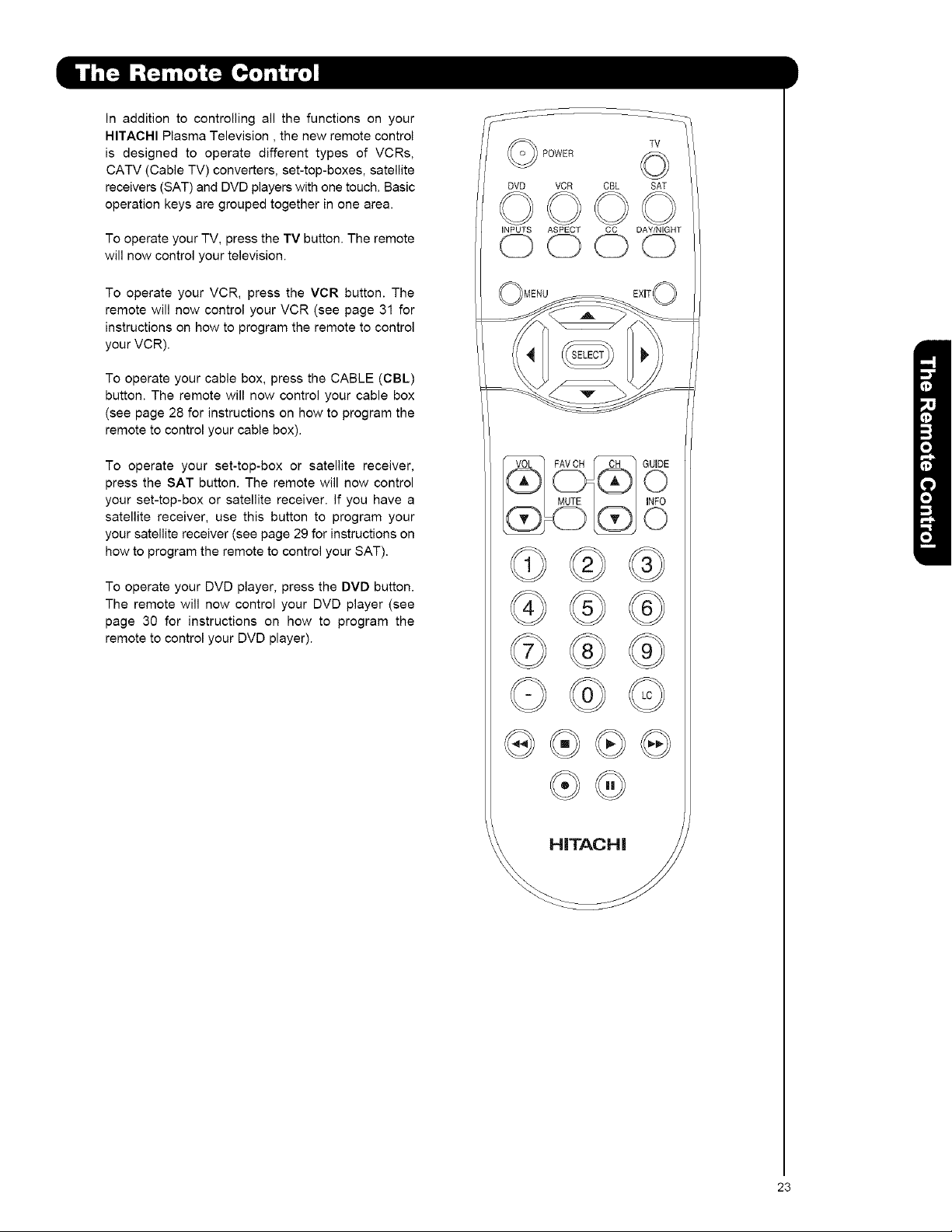
In addition to controlling all the functions on your
HITACHI Plasma Television, the new remote control
is designed to operate different types of VCRs,
CATV (Cable TV) converters, set-top-boxes, satellite
receivers (SAT) and DVD players with one touch. Basic
operation keys are grouped together in one area.
To operate your TV, press the TV button. The remote
will now control your television.
To operate your VCR, press the VCR button. The
remote will now control your VCR (see page 31 for
instructions on how to program the remote to control
your VCR).
To operate your cable box, press the CABLE (CBL)
button. The remote will now control your cable box
(see page 28 for instructions on how to program the
remote to control your cable box).
To operate your set-top-box or satellite receiver,
press the SAT button. The remote will now control
your set-top-box or satellite receiver. If you have a
satellite receiver, use this button to program your
your satellite receiver (see page 29 for instructions on
how to program the remote to control your SAT).
To operate your DVD player, press the DVD button.
The remote will now control your DVD player (see
page 30 for instructions on how to program the
remote to control your DVD player).
POWER
DVD VCR CBL SAT
iNPUTS ASPECT CC DAY/NIGHT
TV
OOOO
@@
@
23
I POWER
@
@
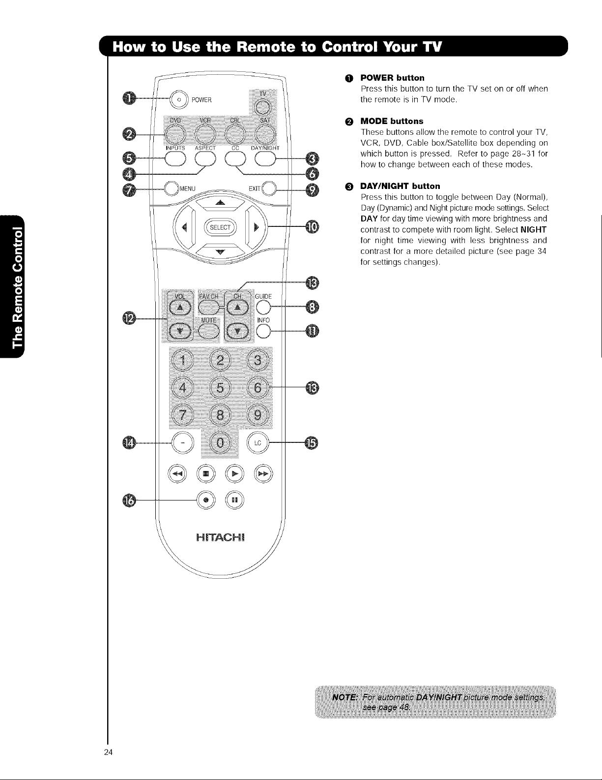
POWER button
0
Press this button to turn the TV set on or off when
the remote is in TV mode.
MODE buttons
0
These buttons allow the remote to control your TV,
VCR, DVD, Cable box/Satellite box depending on
which button is pressed. Refer to page 28-31 for
how to change between each of these modes.
DAY/NIGHT button
0
Press this button to toggle between Day (Normal),
Day (Dynamic) and Nightpicturemode settings.Select
DAY for day time viewing with more brightness and
contrast to compete with room light. Select NIGHT
for night time viewing with less brightness and
contrast for a more detailed picture (see page 34
for settings changes).
24
 Loading...