


SERVICE MANUAL
MANUEL D'ENTRETIEN
WARTUNGSHANDBUCH
SM016
P42T01E
P42T01EA
P42T01U
P42T01UA
P42TP01E
P42TP01U
P50T01E
CAUTION:
Before servicing this chassis, it is important that the service technician read the “Safety
Precautions” and “Product Safety Notices” in this service manual.
ATTENTION:
Avant d’effectuer l’entretien du châassis, le technicien doit lire les «Précautions de sécurité»
et les «Notices de sécurité du produit» présentés dans le présent manuel.
VORSICHT:
Vor Öffnen des Gehäuses hat der Service-Ingenieur die „Sicherheitshinweise“ und „Hinweise
zur Produktsicherheit“ in diesem Wartungshandbuch zu lesen.
P50T01EA
P50T01U
P50T01UA
P50TP01E
P50TP01U
P50TP01EA
P50TP01UA
Data contained within this Service
manual is subject to alteration for
improvement.
Les données fournies dans le présent
manuel d’entretien peuvent faire l’objet
de modifications en vue de perfectionner
le produit.
Die in diesem Wartungshandbuch
enthaltenen Spezifikationen können sich
zwecks Verbesserungen ändern.
SPECIFICATIONS AND PARTS ARE SUBJECT TO CHANGE FOR IMPROVEMENT
Plasma TV
May 2007
P50T01U/E P50TP01U/E P42T01U/E P42TP01U/E
Contents
1. Features -----------------------------------------------2
2. Specifi cations -----------------------------------------4
3. Servicing ----------------------------------------------- 5
4. Component names ----------------------------------6
5. Adjustment -------------------------------------------- 9
6. Troubleshooting ------------------------------------ 14
7. Self-diagnosis function --------------------------- 26
8. Block diagram -------------------------------------- 28
9. Connection diagram ------------------------------ 29
10.Wiring diagrams ----------------------------------- 30
11.Disassembly diagrams -------------------------- 34
12.Replacement parts-------------------------------- 36
13.Circuit diagrams ------------------------------------ 37
CAUTION FOR SAFETY
Please read this page before repairing the monitor.
This page explains the following items for keeping the safety of the set and preventing
accidents during repair.
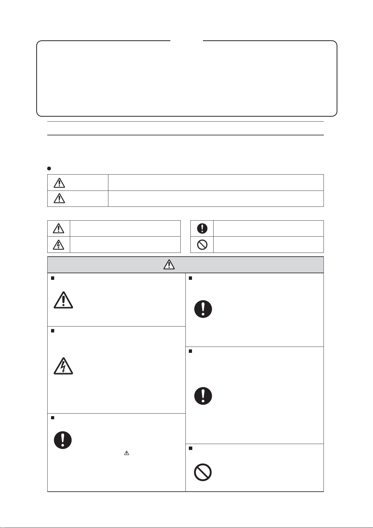
Symbols used:
Warning
Caution
This symbol means "CAUTION"
This symbol means "POSSIBILITY of
ELECTRIC SHOCK"
This symbol means "possibility of death or heavy damage"
This symbol means "possibility of damage or break age"
Follow instructions.
Special attention parts are indicated
on cabinet, chassis and parts by label.
Please follow the notes in [Safety Instructions] in the User’s Manual.
Prevent electric shock.
Take care during working because
the monitor has high voltage parts
and power supply parts.
Possibility of electric shock if these
parts are touched.
Disconnect the mains plug during
overhaul, reassembly or parts change.
Death or injury by electric shock may
occur if live parts are touched.
Use recommended components.
Components and parts with special
characteristics for safety or reliability
are indicated in parts lists and circuit
diagrams by the
Electric shock or fire may occur if non-
recommended components or parts
are used.
mark.
This symbol means "MUST"
This symbol means "DO NOT"
WARNING
Keep the same style of wiring.
The Monitor uses insulating tubes
or tapes for safety and some components are kept at a distance from
PCB surfaces for safety.
Internal leads are kept from hot- or high
voltage parts by clampers or styling.
Return wiring to original condition after
repair to prevent electric shock or fire.
Perform safety check after finishing.
Every part (removed screws, components and wiring) should be returned
to its original condition.
Check around the repair position for
damage and measure insulation
impedance by using a meg-ohm meter.
Confirm that the value of impedance
is more than 4M ohm.
Electric shock or fire may occur if
the value is less than 4M ohm.
The code and combination circuit of the
HDCP is not a repairable item.
Never remove the shield case that is
assembled to the code and combination
circuit of the HDCP.
1
P50T01U/E P50TP01U/E P42T01U/E P42TP01U/E
PRECAUTIONS
Cleaning the plasma screen panel of the monitor
Before cleaning the monitor, turn off the monitor and disconnect the power plug from the power outlet.
To prevent scratching or damaging the plasma screen face, do not knock or rub the surface with sharp or
hard objects. Clean the screen with a soft cloth moistened with warm water and dry with a soft cloth. If this
is not sufficient, use a cloth with mild detergent. Do not use harsh or abrasive cleaners.
Cleaning the cabinet of the monitor
Use a soft cloth to clean the cabinet and control panel of the monitor. When excessively soiled dilute a neutral detergent in water, wet and wring out the soft cloth thenwipe with a dry soft cloth.
Never use acid/alkaline detergents, alcoholic detergents, abrasive cleaners, soap powder, OA cleaners, car
wax, glass cleaners, etc. because these cause discoloration, scratches or cracks.
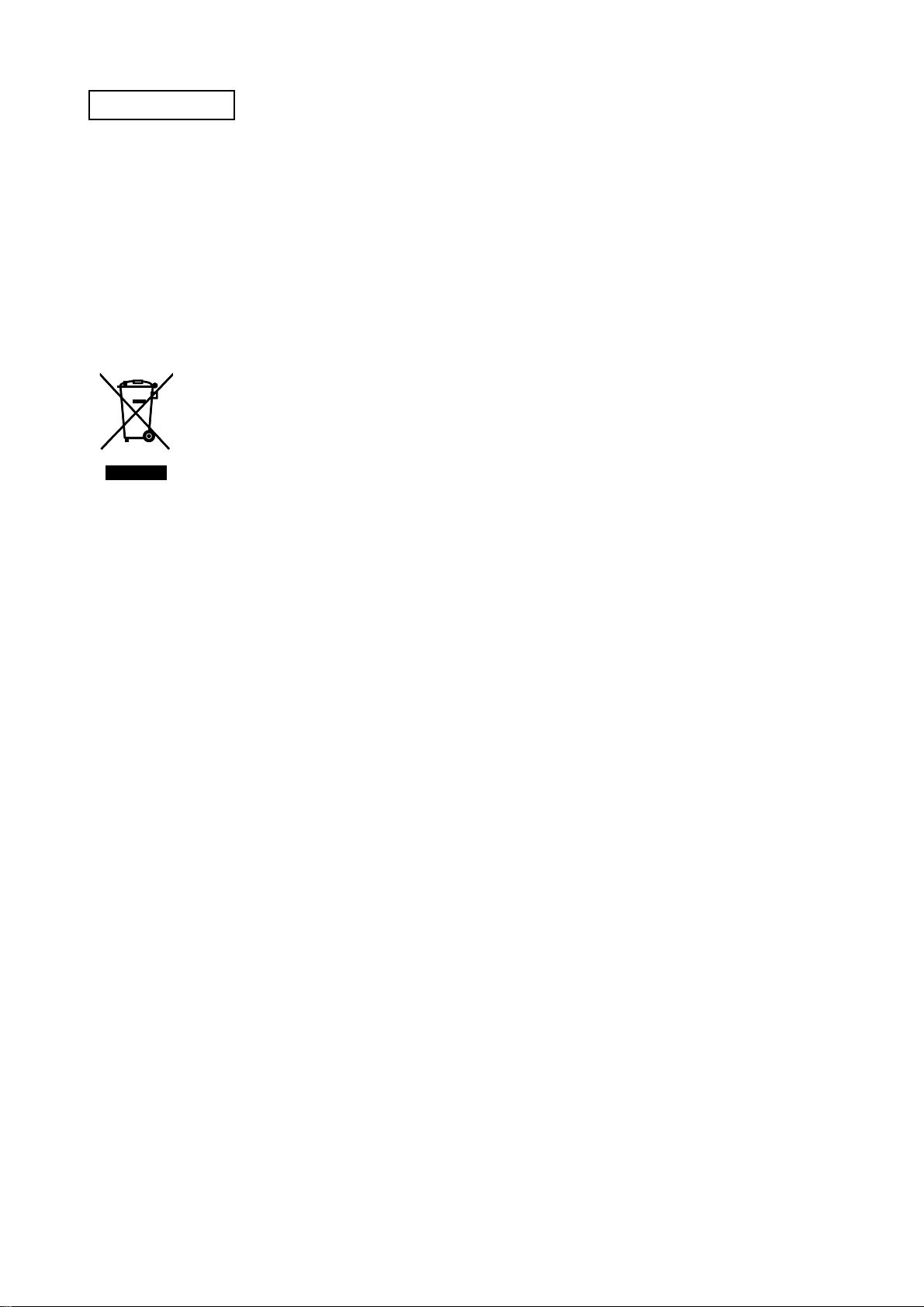
Information for users applicable in European Union countries
This symbol on the product or on its packaging means that your electrical and electronic
equipment should be disposed at the end of its life separately from household waste.
There are separate collection systems for recycling in EU. For more information, please contact the local authority or the dealer where you purchased the product.
1. Features
Large-screen, high-definition plasma display panel
The 50-inch colour plasma display panel, with a resolution of 1280 (H) x 1080 (V) pixels, and the 42-inch colour plasma
display panel, with a resolution of 1024 (H) x 1080 (V) pixels, creates a high-definition, large-screen (aspect ratio:
16:9) and low-profile flat display. Free from electromagnetic interferences from geomagnetic sources and ambient
power lines, the panel produces high-quality display images free from colour misconvergence and display distortion.
High Performance Digital Processor
A wide range of input signals can be handed, including composite, component and HDMI. High Definition Digital
Processor creates the fine-textured image with dynamic contrast.
Easy-to-use remote control and on-screen display system
The remote control included eases the work of setting display controls. Further, the on-screen display system displays the status of signal reception and display control settings in an easy-to-view fashion.
Connecting to an Audio Visual Device
• Three Scart terminals
added. A composite video output terminal is also provided as a monitoring output.
*1
AV1 scart applies composite/ S-video
AV2 and 3 scart applies composite/ RGB
*2
AV5 composite/S-Video=Side Input
*3
AV4 can be connected to the equipment with either component or composite Output.
SD card slot installed
*1
, composite/S terminal*2, a component terminal*3and two HDMI terminals have been
Power Swivel Feature
Allows turning the plasma display left or right within ±30 degree using the remote control.
2

P50T01U/E P50TP01U/E P42T01U/E P42TP01U/E
Digital Terrestrial Television Broadcasting
Converting to digital signal enables more channels and add various useful features, such as Electric
Programme Guide, Digital Teletext and so on. Further, digital signal can create a high quality picture.
This logo indicates that the product is compliant with European Digital Broadcasting.
DVB is a registered trademark of the DVB Project.
This logo indicates that the product is set up to view digital terrestrial TV.
FREEVIEW and the FREEVIEW logo are trade marks of DVT Services Ltd and are used under license.
FREEVIEW Logo © DTV Services Ltd 2002.
3
P50T01U/E P50TP01U/E P42T01U/E P42TP01U/E
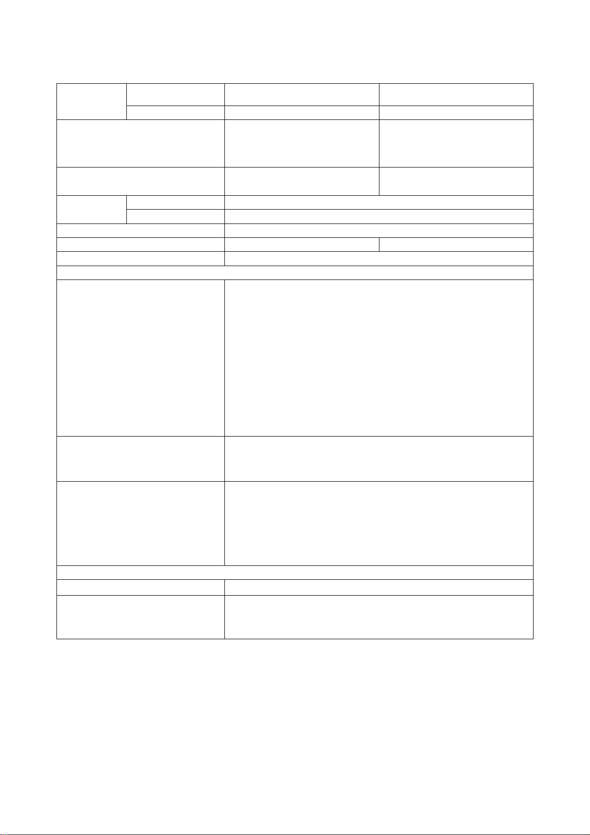
2. Specifications
Panel
Net dimensions
Net weight
Ambient
conditions
Display dimensions
Resolution 1280(H) x 1080 (V) pixels 1024(H) x 1080 (V) pixels
Temperature Operating: 5°C to 35°C, Storage: 0°C to 40°C
Relative humidity Operating: 20% to 80%, Storage: 20% to 90% (non-condensing)
Power supply
Power consumption/ at standby
Audio output Speaker total 20W
(VIDEO input)
Input terminals
Input signals
Output Signals
(RF input)
Input terminal / Receiving range ANT: 75 Unbalanced / 40~870MHz
Approx. 50 inches
(1106(H) x 626(V) mm, diagonal 1270mm)
including Stand:
1240(W)x883(H)x423(D) mm
excluding Stand:
1240(W)x821(H)x128(D) mm
including Stand: 47.0kg
excluding Stand: 41.0kg
AC 220~240V, 50Hz
451W / <0.8W 353W / <0.8W
AV1 : composite video input terminal (SCART)
S video input terminal (SCART)
L/R audio input terminal (SCART)
AV2•3 : composite video input terminal (SCART)
RGB video input terminal (SCART)
L/R audio input terminal (SCART)
AV4 : composite video input terminal (RCA)
component video input terminal.(RCA)
L/R audio input terminal (RCA)
AV5 : composite video input terminal (RCA)
S video input terminal (Mini DIN)
L/R audio input terminal (RCA)
HDMI 1•2 : HDMI input terminal
Audio input terminal (3.5mm Stereo Mini Jack)
Photo Input : Photo Input terminal / SD card slot
Composite video: PAL, SECAM, NTSC3.58, NTSC4.43, PAL60
Component video: 480i, 576i, 480p, 576p, 720p/50, 720p/60, 1080i/50, 1080i/60
HDMI: 480i, 576i, 480p, 576p, 720p/50, 720p/60, 1080i/50, 1080i/60, 1080p/50,
1080p/60
OUTPUT (MONITOR): composite video monitor-output terminal (RCA)
OUTPUT (MONITOR): L/R audio monitor- output terminal (RCA)
OUTPUT (HEADPHONE): L/R audio monitor- output terminal (3.5mm Stereo Mini Jack)
AV1 : composite video output terminal (SCART)
L/R audio output terminal (SCART)
AV2•3 : composite video output terminal (SCART)
L/R audio output terminal (SCART)
Optical Out: PCM
Approx. 42 inches
(930(H) x 523(V) , diagonal 1060mm)
including Stand:
1060(W)x780(H)x360(D) mm
excluding Stand:
1060(W)x710(H)x110(D) mm
including Stand: 36.2kg
excluding Stand: 29.2kg
RF Video System
• The unit takes at least 30 minutes to attain the status of optimal picture quality.
PAL B, G, H / I / D, K
SECAM B, G / K1 / L, L' / D,K
DVB-T
4
P50T01U/E P50TP01U/E P42T01U/E P42TP01U/E
3. Service points
Lead free solder
This product uses lead free solder (unleaded) to help preserve the environment. Please read these
instructions before attempting any soldering work.
Caution: Always wear safety glasses to prevent fumes or molten solder from getting into the eyes. Lead
free solder can splatter at high temperatures (600˚C).
Lead free solder indicator
Printed circuit boards using lead free solder are engraved with an "F."
Properties of lead free solder
The melting point of lead free solder is 40-50˚C higher than leaded solder.
Servicing solder
Solder with an alloy composition of Sn-3.0Ag-0.5Cu or Sn-0.7Cu is recommended.
Although servicing with leaded solder is possible, there are a few precautions that have to be taken. (Not
taking these precautions may cause the solder to not harden properly, and lead to consequent malfunctions.)
Precautions when using leaded solder
Remove all lead free solder from soldered joints when replacing components.
If leaded solder should be added to existing lead free joints, mix in the leaded solder thoroughly after the
lead free solder has been completely melted (do not apply the soldering iron without solder).
Servicing soldering iron
A soldering iron with a temperature setting capability (temperature control function) is recommended.
The melting point of lead free solder is higher than leaded solder. Use a soldering iron that maintains a high
stable temperature (large heat capacity), and that allows temperature adjustment according to the part being
serviced, to avoid poor servicing performance.
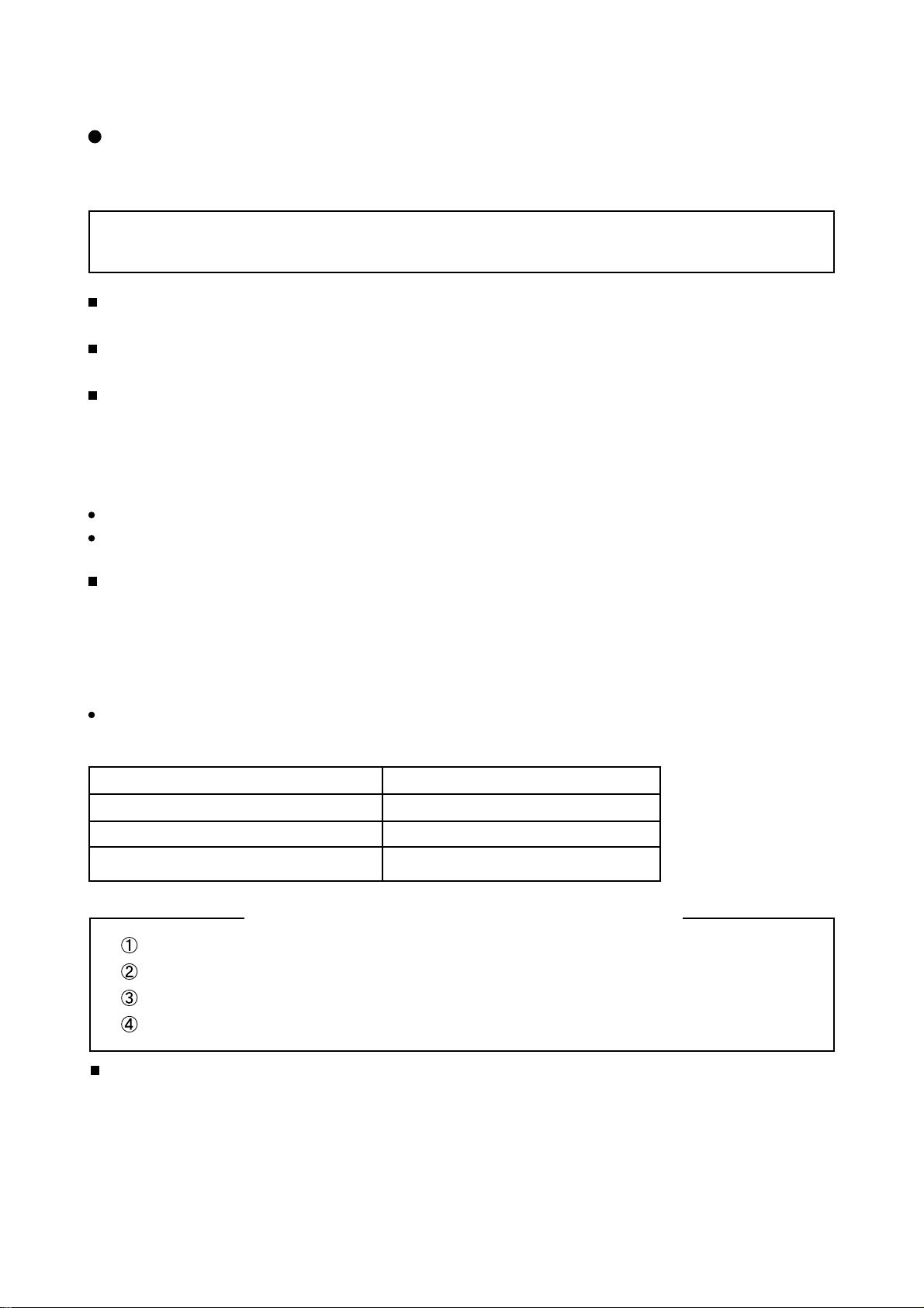
Recommended soldering iron:
Soldering iron with temperature control function (temperature range: 320-450˚C)
Recommended temperature range per part:
Part Soldering iron temperature
Mounting (chips) on mounted PCB 320˚C±30˚C
Mounting (chips) on empty PCB 380˚C±30˚C
Chassis, metallic shield, etc. 420˚C±30˚C
Boards which use lead free solder
CONTROL PCB (Control PCB, Slot PCB, SD PCB)
TERMINAL PCB (Terminal PCB, LED PCB, Swivel PCB)
FILTER PCB
MAIN PCB
Readjustment Power supply voltage
When a PANEL or a Power Unit is exchanged, power supply voltage needs to be adjusted. Please adjust to
make the values of Va and Vs of as should on the label currently stuck on the panel back upper parts.
Adjustment is performed by VR in the power supply unit. Please refer to the procedures of “Va” and “Vs”
adjustments on page 10.
5
P50T01U/E P50TP01U/E P42T01U/E P42TP01U/E
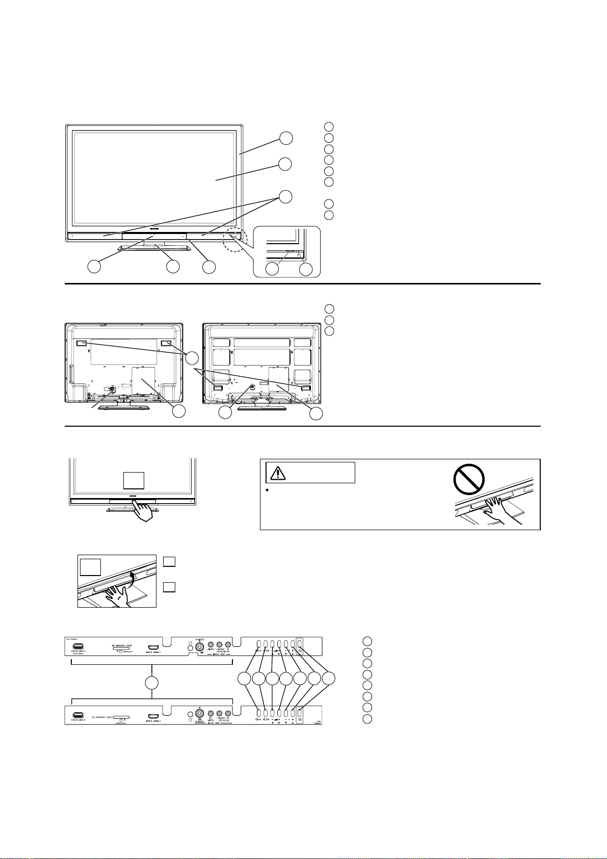
4. Component names
[Main unit]
Front Panel
1 Cabinet
1
2
8
2 Panel
3 Remote Control Receiver
4 Indicating Lamp
5 Main Power Switch (on the bottom surface)
6 Control Panel and Front Input (see below for
details)
7 Desktop Stand
8 Speaker
6
7
5
43
Rear Panel
42” models
50” models
3
2
Control Panel (including front input)
1
2
A
Do not place your fingers into the gap of
the opened door. If your fingers are caught
in the front door, you may be injured.
Push here to open the door.
B
A Push the bottom centre of
the front door to unlock.
B Lift it up from the
underside of the door.
1 Terminal Board (External Device Connection)
2 Power Cord Socket
3 Handgrips
1
CAUTION
42” models
50” models
1 Front Input
2 Menu/Return button
3 Input Select/OK button
4
6
1
23
5
8
7
6
4 Volume Down/Żbutton
5 Volume Up/Źbutton
6 Channel Down/źbutton
7 Channel Up/Ÿbutton
8 Sub Power button
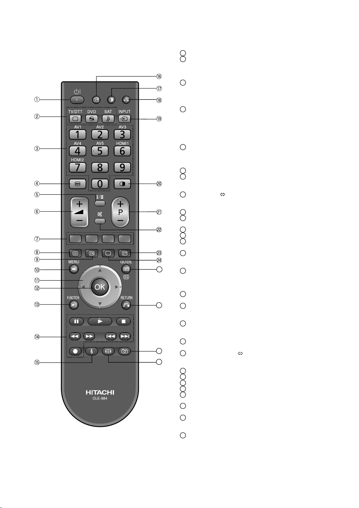
[Remote control]
P50T01U/E P50TP01U/E P42T01U/E P42TP01U/E
Sub Power
1
Function Select (TV/DTT, DVD, SAT)
2
Press these buttons to select function mode.
The selected button blinks once. Normally,
select “TV/DTT”.
Programme Select/Input Mode [Page Select]
3
Press these buttons to select a TV programme directly.
You can also use these buttons when changing
the Input mode.
Freeze/Multi Mode [Hold]
4
Press this button to change the picture to freeze
mode. Press it again to return to normal picture.
In addition, during multi-picture mode, this
changes the type of 2-Picture mode.
(Also, it holds the page in teletext mode.)
CHI/II
5
This is exclusively for TV audio A2/NICAM
mode. Also, press this button to select Audio
Language in DTT mode.
Volume Up/Down
6
Colour [Colour]
7
These coloured buttons are for teletext and
other functions as detailed later in this book.
25
26
27
28
TV/Text [TV
8
This switches between the TV mode and the
Teletext mode.
[Cancel]
9
10
Menu
Press this button to select Main Menu.
Cursor [Item Select]
11
OK
12
Function Menu
13
Press this button to select Function Menu.
DVD Control
14
You can use these buttons whilst operating the
selected brand of DVD player.
Audio Mode
15
Audio mode can be changed each time pressed
in the following sequence. MovieĺMusicĺ
SpeechĺFavourite
16
Recall
Press this button to show the input signal status.
17
Picture Mode
Picture mode can be changed each time pressed in
the following sequence. DynamicĺNaturalĺCinema
18
Swivel (with Desktop Stand)
This function is to rotate TV. Select the degree
of rotation with cursor key.
Input Select
19
You can use this to change the input mode.
Multi Picture [Text
20
Press this button to change the picture to multi-picture
mode. Press it again to return to normal picture.
Channel Up/Down [Page Select]
21
Mute
22
[Reveal]
23
[Subtitle]
24
Guide [Index]
25
It displays EPG screen in DTT mode.
26
Return
You can use this to return to the previous menu.
27
Photo Input
This button is to display and control the pictures from
digital still camera, USB card reader, or SD (MMC) card.
28
Zoom
Press this button to change picture size.
Text]
TV+Text]
The function indicated by [ ] are only for Teletext mode.
7
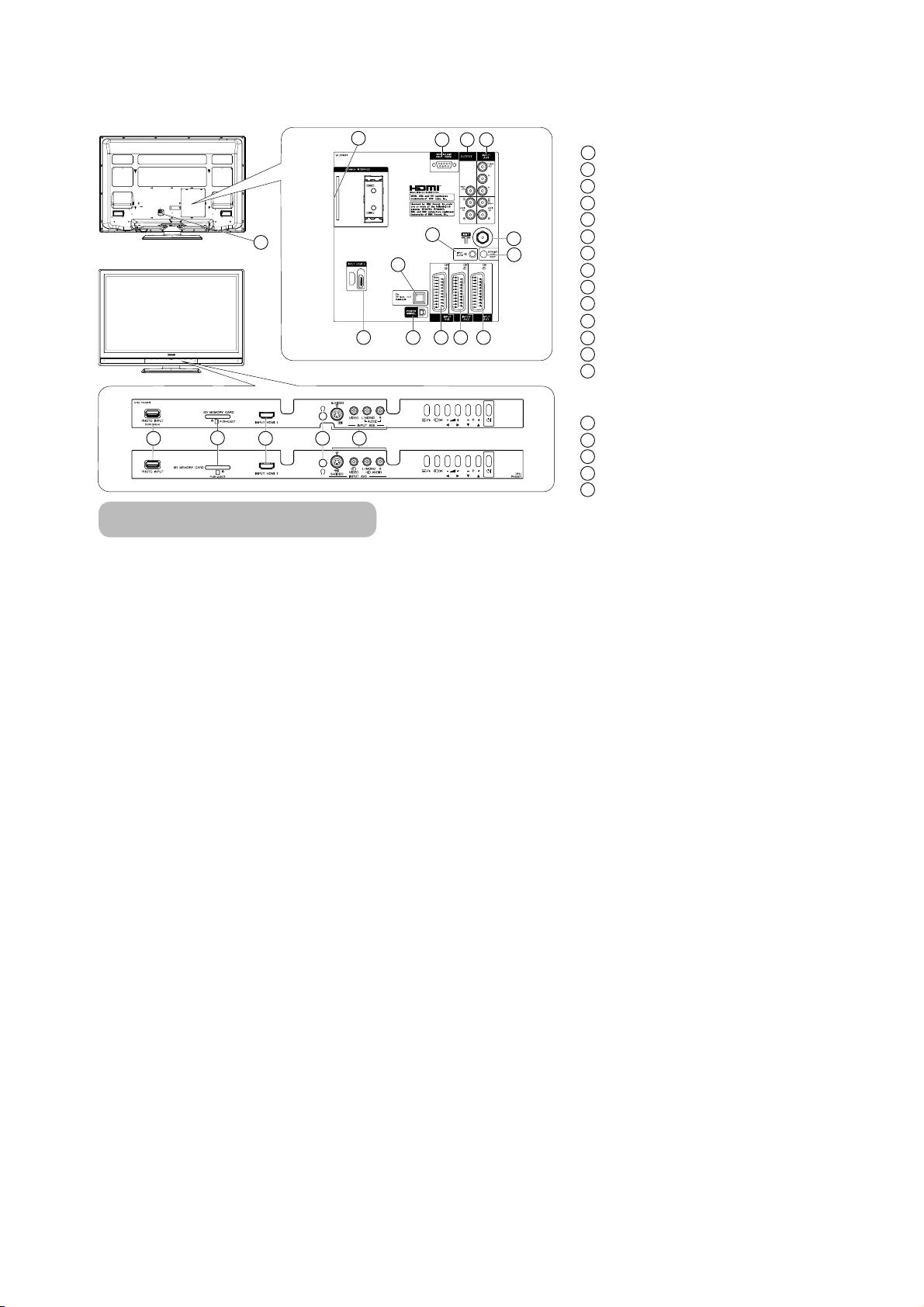
[Terminal Positions]
P50T01U/E P50TP01U/E P42T01U/E P42TP01U/E
Rear
1
Power Cord Socket
2
Aerial Socket
3
AV1
4
AV2
5
AV3
6
AV4
7
Monitor Out
8
Service use only
9
Service use only
10
Power Swivel Terminal
11
Optical Out (Digital Audio)
12
HDMI 2
13
Mini stereo for Audio
14
Common interface slot
[Example: 50’’ models]
42’’ models
14
1
12
13
11
10
678
2
9
3
4
5
Front
AV5
15
Headphone terminal
16
HDMI 1
17
SD Memory Card slot
18
19
Photo Input terminal
50’’ models
19
18
17
16
15
Connecting Procedure
This unit is ready for various kinds of connections. Make a connection in the following steps. Be sure to turn off the
Main Power first when connecting external equipment.
1. Connect Power Cord to the rear panel.
2. Connect Aerial Lead.
3. Connect your external equipments to the unit if any.
4. Connect the Power Plug to the Wall Socket.
8
P50T01U/E P50TP01U/E P42T01U/E P42TP01U/E
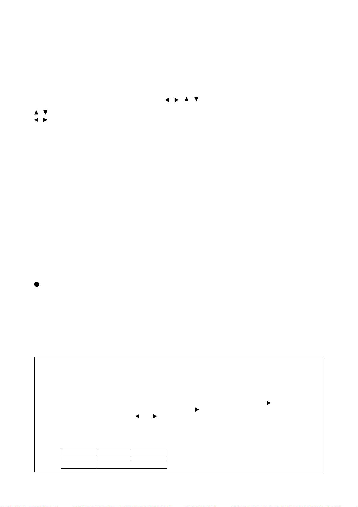
5. Adjustment
Ɣ Activating Adjustment Mode
Use the remote controller with the set turned on to activate adjustment mode.
Press the Programme Select button “1”, “GREEN” and “YELLOW” colour button at the same time and hold for
more than 3 seconds.
The set displays adjustment mode.
Ɣ Changing data and Selecting Adjustment code
When the set is in adjustment mode, the cursor
used as adjustment keys.
buttons are used for selecting adjustment code.
,
, buttons are used for changing data values.
OK button is used for confirming data.
After finishing adjustments press, the RETURN button. Adjustment mode is released and the set
returns to normal condition.
Ɣ Memory Initialise operation
NOTE: The execution of this function returns the adjustment codes to preset values, therefore, adjust-
ment data will be lost.
When performing MEMORY INITIALISE, the following items are not initialised.
• WHITE/BALANCE ADJUSTMENT DATA
• SUB CONTRAST ADJUSTMENT DATA
• CLANP OFFSET ADJUSTMENT DATA
However, the following items are initialised.
• OTHER ADJUSTMENT DATA
• FACTORY RESET ITEM
Procedure
(1) Enter Adjustment Mode.
(2) Select MEMORY INIT.
(3) Activate MEMORY INIT by pressing cursor “Right” button for more than 3 seconds.
(4) As for the whole Memory Initialise, the cyan screen becomes a green screen.
It becomes a red screen in the case of abnormality.
, , , and OK buttons of the remote control may be
Ɣ Checking accumulated time of panel.
Mentioned in the menu of the last item.
Factory Reset
After all of adjustments of the main chassis are finished, perform a FACTORY RESET.
Procedure
(1) Enter Adjustment Mode.
(2) Select FACT RESET.
(3) Activate FACT RESET by pressing cursor Right button for more than 3 seconds.
The unit is set to factory settings.
Ɣ When flicker is present set contrast mode of picture menu to Normal and set Black enhancement
to off.
Caution: After upgrading software of the main microcomputer, display a teletext screen
and confirm whether a screen position is right.
If an indication point is unusual, adjust using the following method:
Procedure
(1) Enter Adjustment Mode.
(2) Select DEVICE.
(3) When indication is replaced, input a device number into DEVICE and press OK or [
Next, input an item number into ITEM and press OK or [
Lastly, change data by pressing [ ] or [ ] into DATA and press OK.
Continue input for the next DEVICE, then push [ź] after the DATA input.
Perform the above for the following items:
(If you make a mistake entering the input number, push RETURN to go to the previous step.)
DEVICE ITEM DATA
9 107 f8
16 4 b
].
].
9
P50T01U/E P50TP01U/E P42T01U/E P42TP01U/E
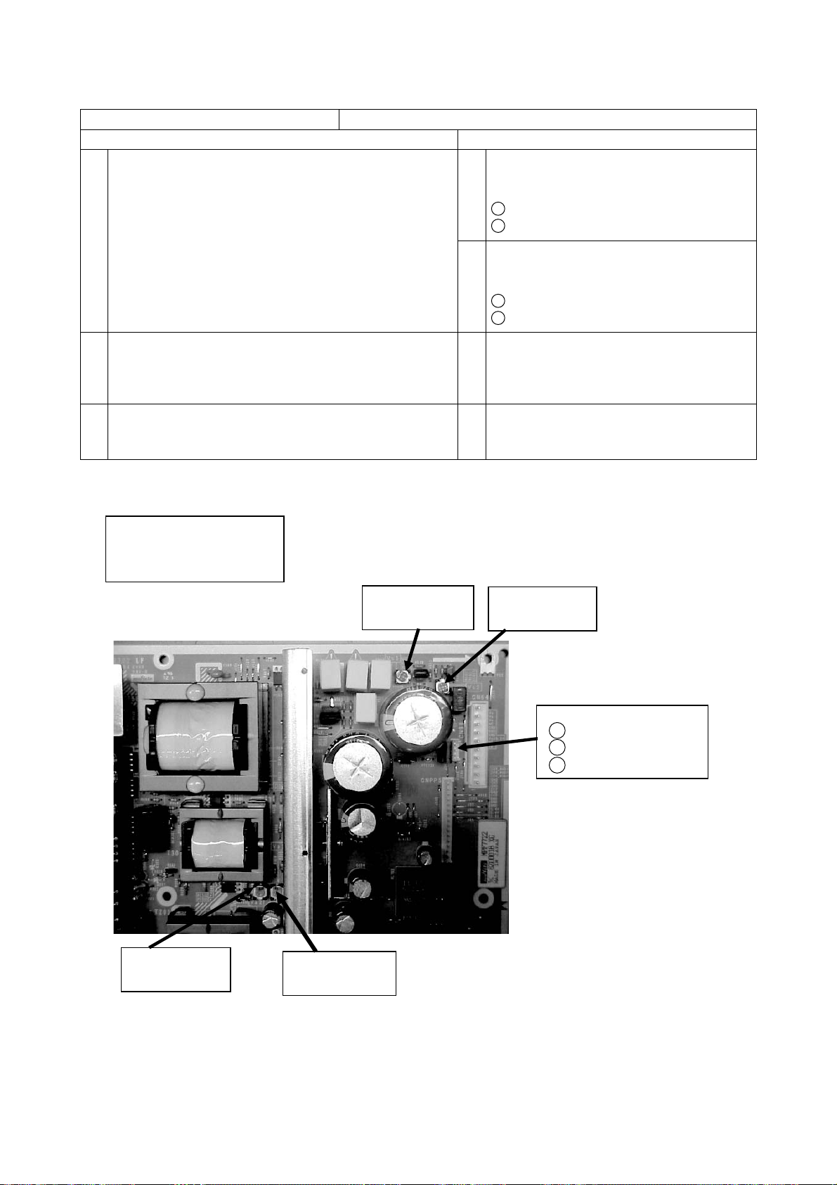
50PDP Vs and Va Adjustment
Item Power Unit Vs, Va Adjustment
Preparation Procedure
(1) Turn on the set and perform
pre-heat run for more than 1 min
on burn-in screen.
(1) Turn Vs ADJ to adjust Vs voltage
to within ±0.1V of the value
specified in the label on the panel.
1
Adjust within ±1V at Vs1
2
Adjust within ±0.1V at Vs2
(2) Turn Va ADJ to adjust Vs voltage
to within ±0.1V of the value
specified in the label on the panel.
1
Adjust within ±1V at Va1
2
Adjust within ±0.1V at Va2
(2) Receive full back pattern signal.
(or Video silence signal; it will
automatically turn off after a few seconds
by the power save function)
(3) Connect voltmeter leads to the Vs (or Va) and
GND test points of the power unit.
Label example
<LOT>N6
Vs=80.0V Va=60.0V
Vw=140.0V Vx=60.0V
Vs1: Vs coarse
adjustment VR
(3) Reconfi rm that Vs voltage remains within
±0.45V of the specifi ed value.
Readjust if outside of the margin.
(4) Reconfi rm that Va voltage remains within
±0.55V of the specifi ed value.
Readjust if outside of the margin.
Vs2: Vs fine
adjustment VR
CN99: Vs,Va test points
GND
3
2
Vs
1
Va
Va2: Va fine
adjustment VR
Caution: 42PDP does not require adjustment. ( 42PDP is self-adjustmenting.)
Va1: Va coarse
adjustment VR
10
P50T01U/E P50TP01U/E P42T01U/E P42TP01U/E
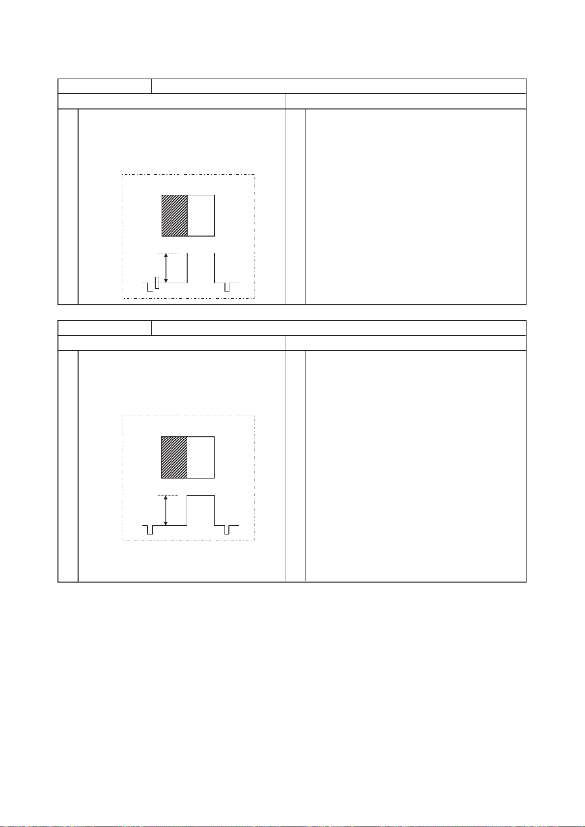
RGB Amplitude Adjustment (AV Component Input)
Item
Composite video Adjustment
Preparation Procedure
(1)
Allow the set to heat-run for more than 20
minutes before the final adjustment.
(2)
Input composite video adjustment signal into
AV1 terminal.
Adjustment signal for CVBS format
White
Black
0.7V
Item
Component 480p/480i Adjustment
Preparation Procedure
(1)
Allow the set to heat-run for more than 20
minutes before the final adjustment.
(2)
Input component 480p adjustment signal into
AV4 terminal.
Adjustment signal for 480p/480i format
White
Black
(1)
Receive composite video adjustment signal at AV1
terminal input.
Characters must not be present in both patterns
of Black and White.
(2)
Go into Service Adjustment Menu and select “RGB”.
(3)
Press [►] for over 2 seconds then RGB Amplitude
Adjustment starts automatically.
OSD disappears while the adjustment is operating.
OSD appears again when the adjustment is
completed.
(1)
Receive 480p adjustment signal at AV4
terminal input.
Characters must not be present in both patterns
of Black and White.
(2)
Go into Service Adjustment Menu and select “RGB”.
(3)
Press [►] for over 2 seconds then RGB Amplitude
Adjustment starts automatically.
OSD disappears while the adjustment is operating.
OSD appears again when the adjustment is
completed.
0.7V
(4)
Change signal formal from 480p to 480i.
(5)
Press [►] for over 2 seconds again, then RGB
Amplitude Adjustment starts automatically.
OSD disappears while the adjustment is operating.
OSD appears again when the adjustment is
completed.
11
P50T01U/E P50TP01U/E P42T01U/E P42TP01U/E
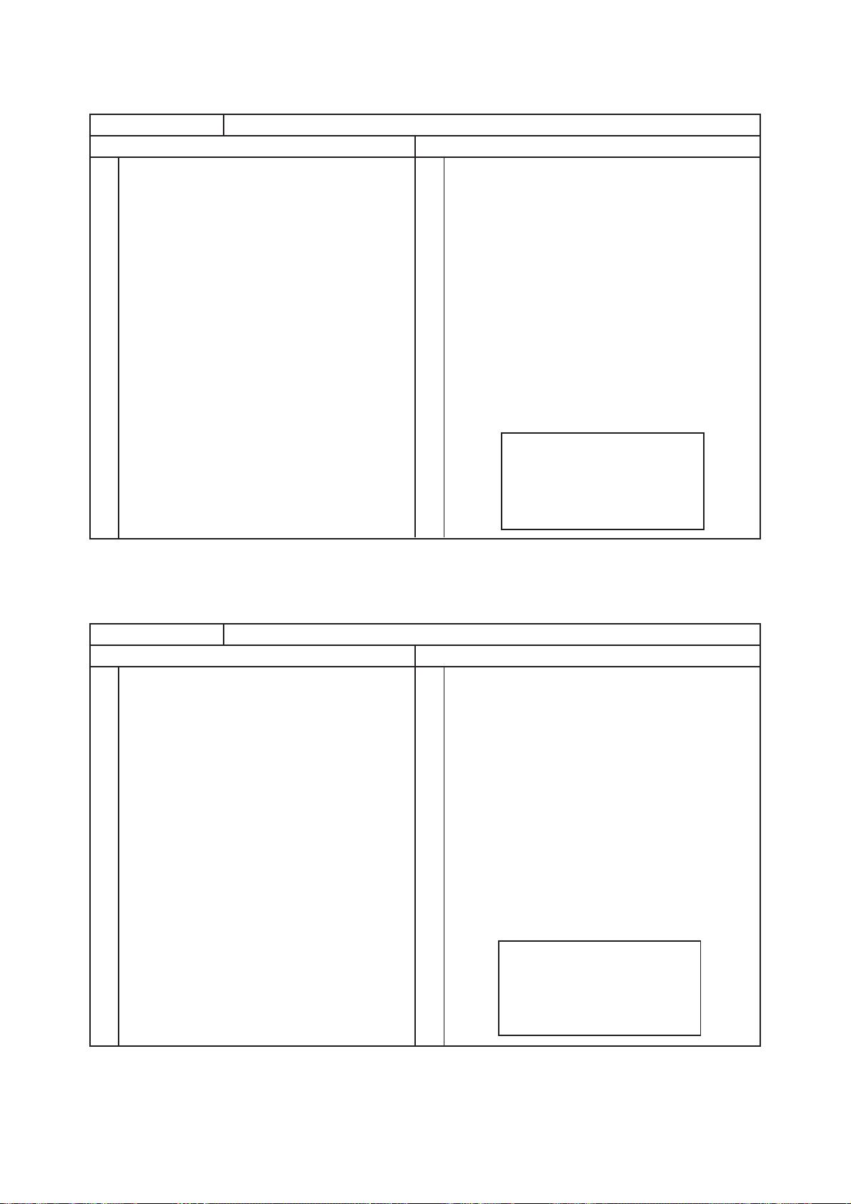
Video Colour Temperature Adjustment
Item
Video Colour Temperature Adjustment (Cool)
Preparation Procedure
(1)
Set the signal generator output to white raster.
(Window ratio: 100%)
(2)
Component signal (576i or 480i)
Video level: 0.700Vp-p
Sync level: 0.300Vp-p
Setup level: 0V
(3)
Input white raster signal into AV4 Component
input terminal.
(4)
Set Picture Menu to Natural mode.
(5)
Check that the mode is set as Factory
Adjustment mode.
(6)
Set aspect to Full mode.
(1)
Perform the following adjustment with the remote
control:
(2)
Set the CRT colour analyzer (CA-100) at the centre
of the panel.
(3)
Set colour temperature to “Cool”.
(4)
Ensure that the adjustment R/G/B DRIVE (COOL)
is all set as 255.
If the values are not 255, set them to 255.
(5)
Receive white raster signal. Step down either
R DRV_COOL, G DRV_COOL or B DRV_COOL
of the two (or, one) values and adjust to the
following value.
(Note) At least one of the data items should be 255.
Specification
Video colour temperature (Cool)
x=0.266±0.005
y=0.270±0.005
14000K + 0MPCD
[Remarks]
(1) Colour temperature should be adjusted under the condition in which the screen is the brightest, thus the initial
value of adjustment is set at maximum.
(2) This adjustment only decreases brightness.
(3) Beware there is RESET in each Picture mode.
Item
Video Colour Temperature Adjustment (Normal)
Preparation Procedure
(1)
Set the signal generator output to white raster.
(Window ratio: 100%)
(2)
Component signal (576i or 480i)
Video level: 0.700Vp-p
(1)
Perform the following adjustment with the remote
control:
(2)
Set the CRT colour analyzer (CA-100) at the centre
of the panel.
Sync level: 0.300Vp-p
Setup level: 0V
(3)
Input white raster signal into AV4 Component
input terminal.
(3)
Set colour temperature to “Normal”.
Ensure that the adjustment R/G/B DRIVE (NORMAL)
(4)
is all set as 255.
If the values are not 255, set them to 255.
(4)
Set Picture Menu to Natural mode.
Receive white raster signal. Step down either
(5)
(5)
Check that the mode is set as Factory
Adjustment mode.
R DRV_NORMAL, G DRV_NORMAL or B
DRV_NORMAL of the two (or, one) values and
adjust to the following value.
(6)
Set aspect to Full mode.
(Note) At least one of the data items should be 255.
Specification
Video colour temperature (Normal)
x=0.285±0.005
y=0.293±0.005
9300K + 0MPCD
[Remarks]
(1) Colour temperature should be adjusted under the condition in which the screen is the brightest, thus the initial
value of adjustment is set at maximum.
(2) This adjustment only degreases brightness.
(3) Beware there is RESET in each Picture mode.
12

P50T01U/E P50TP01U/E P42T01U/E P42TP01U/E
Item
Video Colour Temperature Adjustment (Warm)
Preparation Procedure
(1)
Set the signal generator output to white raster.
(Window ratio: 100%)
(2)
Component signal (576i or 480i)
Video level: 0.700Vp-p
Sync level: 0.300Vp-p
Setup level: 0V
(3)
Input white raster signal into AV4 Component
input terminal.
(4)
Set Picture Menu to Natural mode.
(5)
Check that the mode is set as Factory
Adjustment mode.
(6)
Set aspect to Full mode.
(1)
Perform the following adjustment with the remote
control:
(2)
Set the CRT colour analyzer (CA-100) at the centre
of the panel.
(3)
Set colour temperature to “Warm”.
(4)
Ensure that the adjustment R/G/B DRIVE (WARM)
is all set as 255.
If the values are not 255, set them to 255.
(5)
Receive white raster signal. Step down either
R DRV_WARM, G DRV_WARM or B DRV_WARM
of the two (or, one) values and adjust to the following
value.
(Note) At least one of the data items should be 255.
Specification
Video coloor temperature (Warm)
x=0.314±0.005
y=0.323±0.005
6500K + 0MPCD
[Remarks]
(1) Colour temperature should be adjusted under the condition in which the screen is the brightest, thus the initial value of
adjustment is set at maximum.
(2) This adjustment only degreases brightness.
(3) Beware there is RESET in each Picture mode.
Item
Video Colour Temperature Adjustment (B&W)
Preparation Procedure
(1)
Set signal generator output as All White.
(Window ratio: 100%)
(2)
Component signal (480i)
Video level: 0.700Vp-p
(1)
Perform the following adjustment with remote
control:
(2)
Set the CRT Colour Analyzer (CA-100) at the centre
of the panel.
Sync level: 0.300Vp-p
(3)
Setup level: 0V
(3)
Input white raster signal into AV4 Component
input terminal.
Set colour temperature to “Black&White”.
Ensure that the adjustment R/G/B DRIVE (B/W) is all
(4)
set as 255.
If the values are not 255, set them to 255.
(4)
Set Picture Menu to Natural mode.
Receive white raster signal. Step down either
(5)
Check that the mode is set as Factory Adjustment
(5)
mode.
Set aspect to Full mode.
(6)
R DRV_B/W, G DRV_B/W or B DRV_B/W of the
two (or, one) values and adjust to the following value.
(Note) At least one of the data items should be 255.
Specification
Video colour temperature (B/W)
x=0.335±0.005
y=0.343±0.005
5400K + 0MPCD
[Remarks]
(1) Colour temperature should be adjusted under the condition in which the screen is the brightest, thus the initial
adjustment value is set at maximum.
(2) This adjustment only degreases brightness.
(3) Beware there is RESET in each Picture mode.
13
P50T01U/E P50TP01U/E P42T01U/E P42TP01U/E
6. Troubleshooting
Burn-in mode
This mode displays test patterns of some single colour rasters in turn. These signals are produced by the built-in
generator of the panel. So it can be presumed that the panel has a problem when the Burn-in mode screen
is abnormal.
Using the remote control with the set turned on can activate the mode.
Press the “MENU”, “recall”, “9”, “OK” in turn for less than 2 seconds.
The set turns on with single colour raster and the OSD off [BURN IN: ON].
To escape from this mode, press the “MENU”, “recall”, “9”, “OK” in turn for less than 2 seconds.
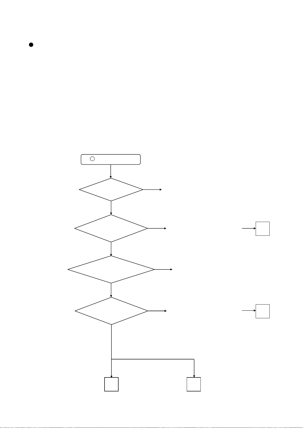
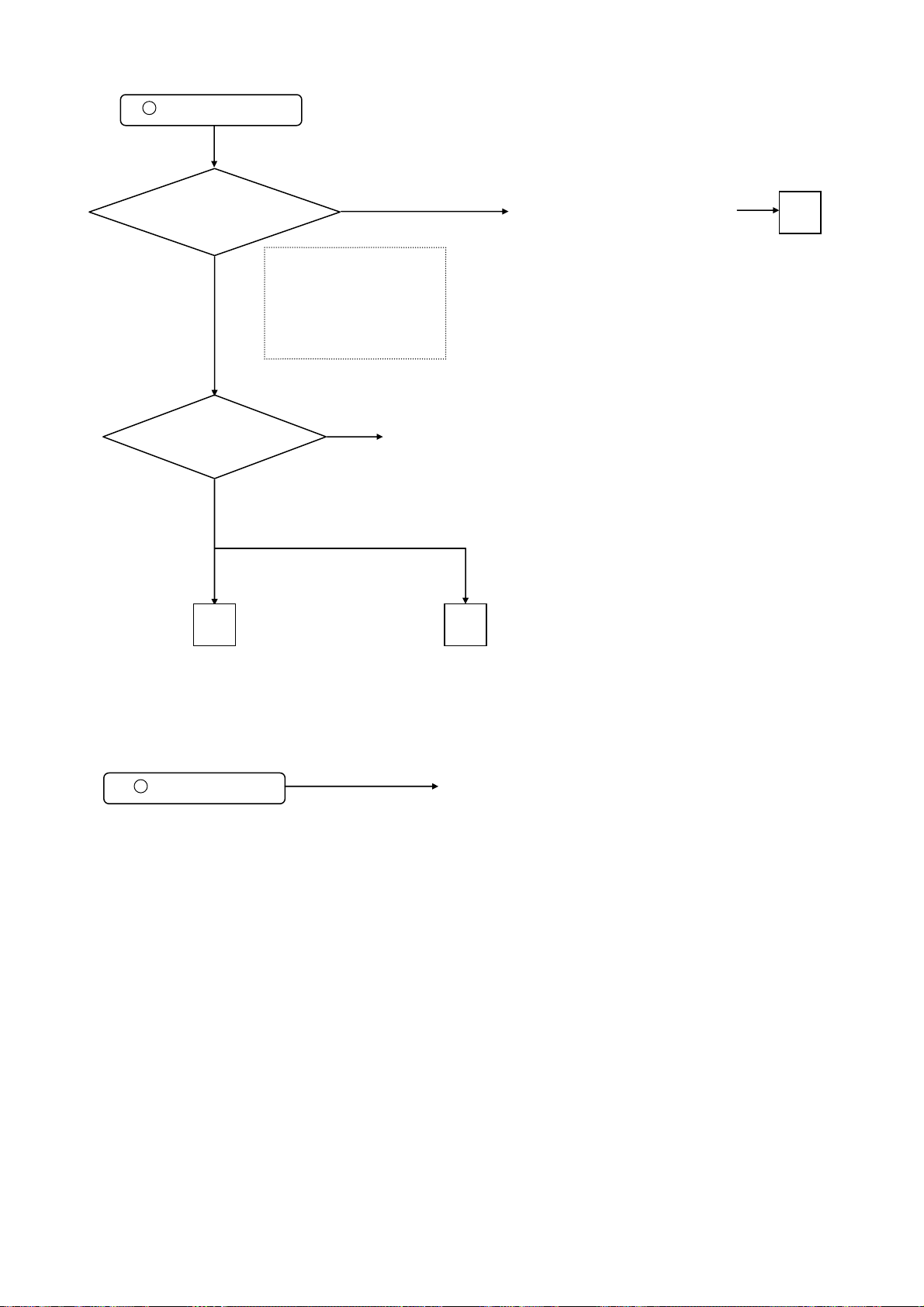
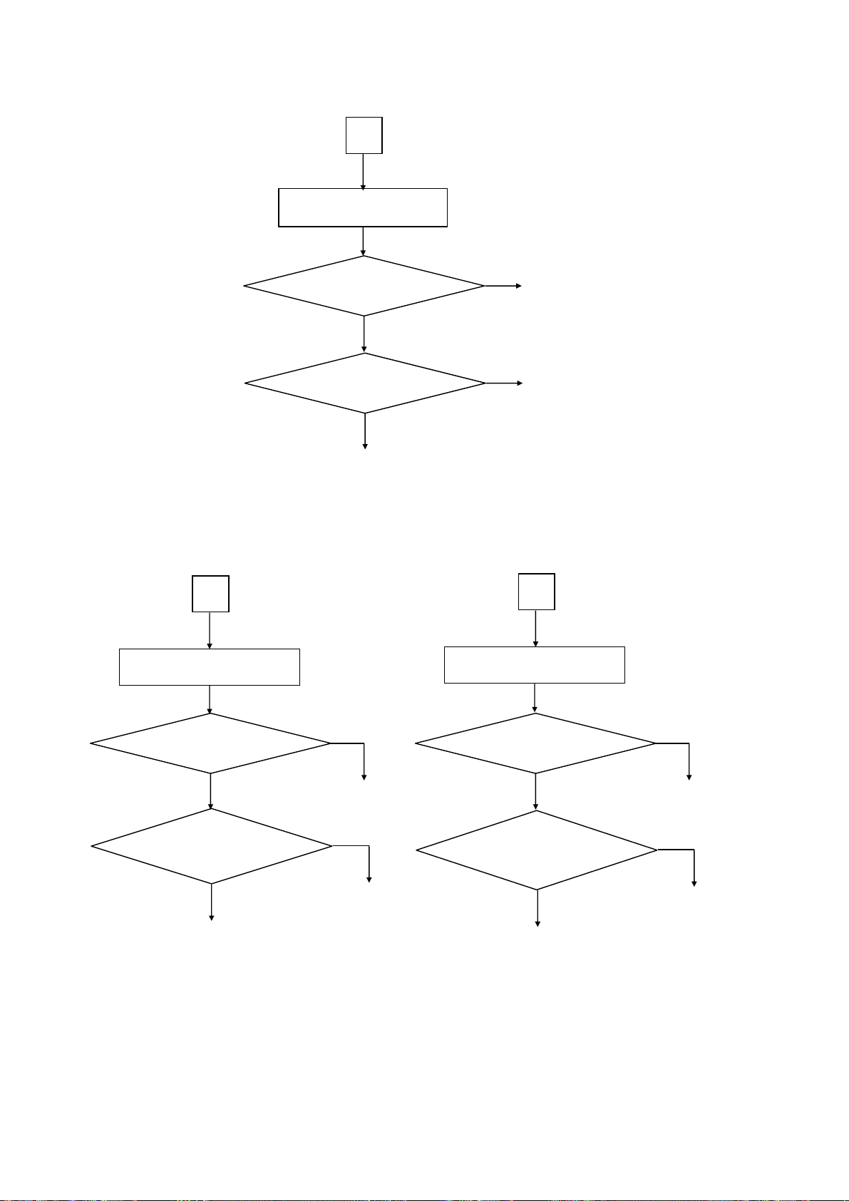
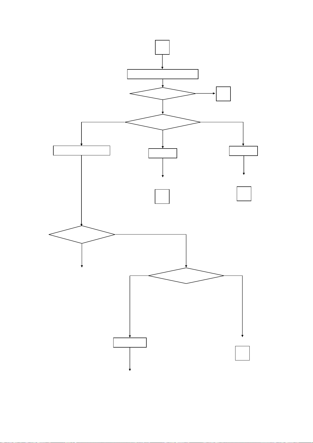
[no picture, no sound]
C onfirm the LED state and examine according to the following Flowcharts:
LED does not light.
1
Is AC Fuse
F9A2 T6.3AH 250V of Filter
PCB normal?
Yes
Is the voltage of pin1(+5.0V)
of PPM1 connector of MAIN
PCB normal?
Yes
Are the voltages of
pin6(+5.0V)/7(+3.3V) of PPM1
connector of MAIN
PCB normal?
Yes
Are the voltages of
pin1/2/3(+5.6V) of PPM2
connector of MAIN PCB
normal?
Yes
No
Change AC Fuse of Filter PCB
No
No
Change MAIN PCB or EPM1 (cable).
If no improvement, go to
Power Supply Unit Troubleshooting
No
Change MAIN PCB or EPM1 (cable)
Change MAIN PCB or EPM2 (cable).
If no improvement, go to
Power Supply Unit Troubleshooting
A
A
B C
Go to Picture Troubleshooting
Go to Sound Troubleshooting
14
LED lights blue.
2
P50T01U/E P50TP01U/E P42T01U/E P42TP01U/E
Are the voltages of PPM1 and PPM2
connector of MAIN PCB normal?
Ye s
Does PDP Burn-In mode
operate normally?
[PPM1] Pin1/4/5/6 (+5.0V)
[PPM2] Pin1/2/3 (+5.6V)
Ye s
B C
No
Pin7/8 (+3.3V)
Pin7 (+10V)
Pin9 (+16V)
Pin13/14/15 (+12V)
No
PDP module
Change MAIN PCB or EPM1/2 (cable).
If no improvement, go toto
Power Supply Unit Troubleshooting
A
Go to PictureTroubleshooting
LED blue blinks blue.
3
Go to Sound Troubleshooting
It is in video input power save mode. This is not a problem.
15
P50T01U/E P50TP01U/E P42T01U/E P42TP01U/E
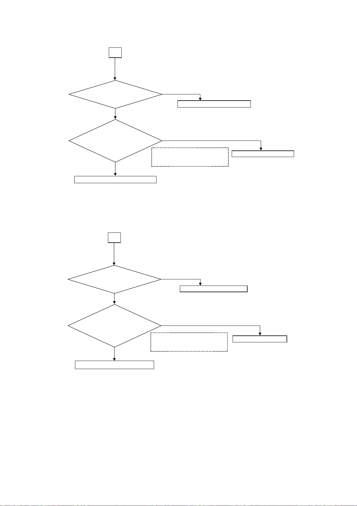
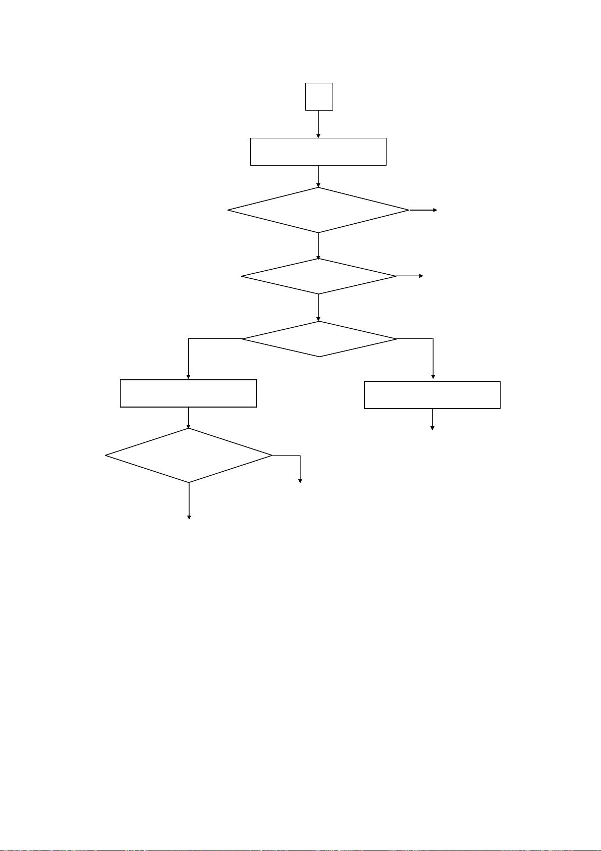
[50PDP Power unit]
A
Is input voltage
applied to Power supply unit ?
(CN61 (1),(3))
㪰㪼㫊
㩷
㩷
Caution: To take off a PPU1 connector,
[42PDP Power unit]
Are the voltages
applied to CN63 (1)(3),
and CNPPS (1)(7)(9)(13) of
Power supply unit ?
㪰㪼㫊
Go to Picture troubleshooting
first take off the filter board and pull up PPU1 connector.
A
㪥㫆
Change AC Fuse F9A2 T6.3AH
㪥㫆
[CN63] (1) +5.3V / (3) +3.3V
[CNPPS] (1) +5.6V / (7) +10.6V
(9) +16.5V / (13) +11.2V
Change Power supply unit
*Re-adjustment is reqired.
Refer to 'Power Unit
Vs ,Va Adjustment' page.
applied to Power supply unit ?
Is input voltage
(CN61 (1),(3))
Yes
Are voltages
applied to CN631),
and CNPPS (1)(7)(9)(13) of
Power supply unit ?
Yes
Go to Picture troubleshooting
Caution: To take off a PPU1 connector.
First take off the filter board and pull up PPU1 connector.
No
AC Fuse F9A2 T6.3AH 250V
No
[CN63] 䇭(1) +5.3V
[CNPPS] (1) +5.6V / (7) +10.6V
(9) +16.5V / (13) +10.6V
Change Power supply
*Re-adjustment is not required.
Vs ,Va Adjustment is
automatic
16
P50T01U/E P50TP01U/E P42T01U/E P42TP01U/E
g
g
g
g
g
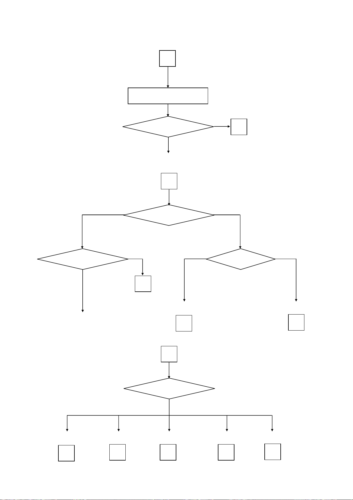
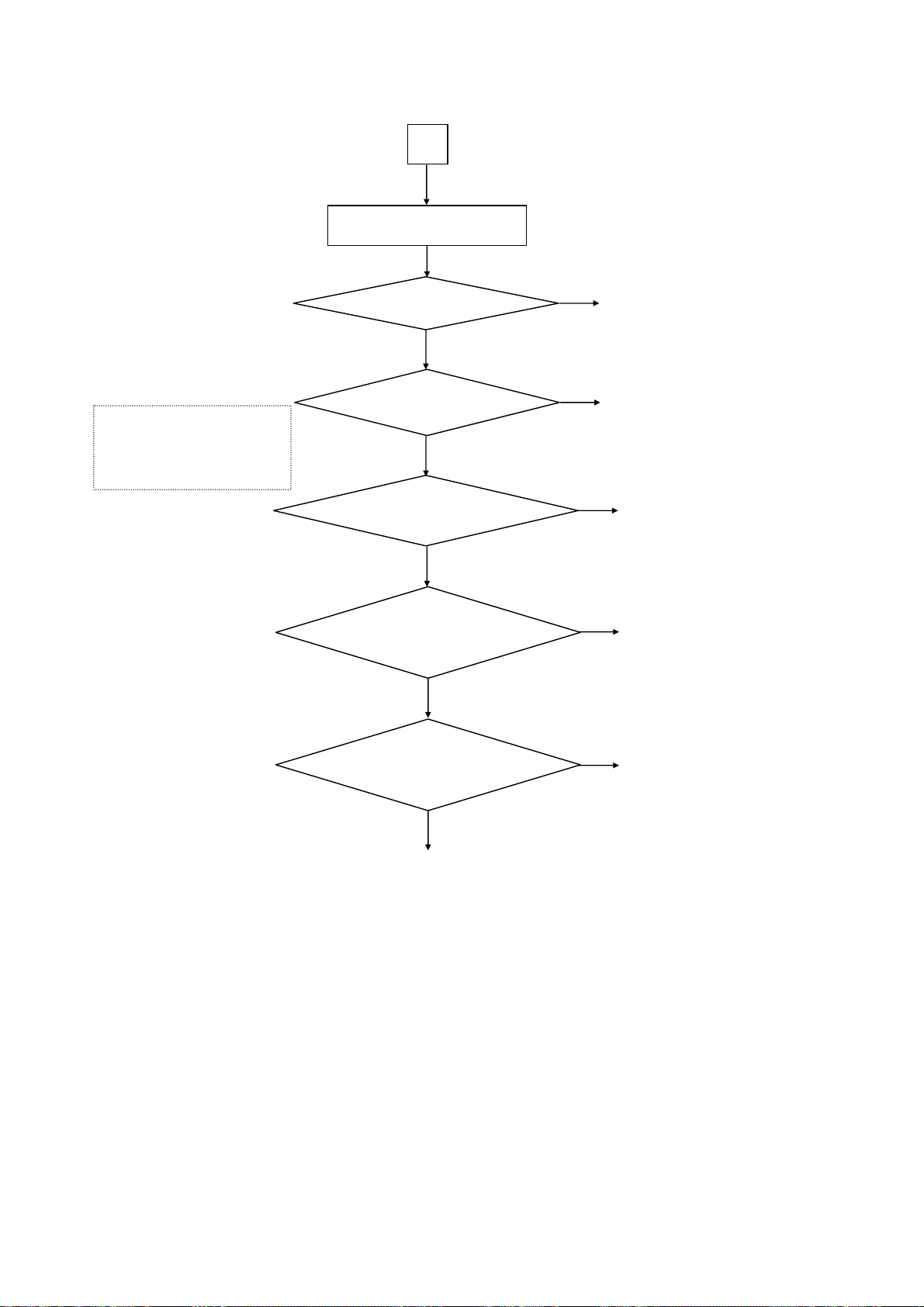
Picture troubleshooting]
B
No picture, no colour or dark
Analog format signals
Are all Analog format
signals abnormal?
Yes
Are all inputs not reflected?
Change MAIN PCB
a
Which input is abnormal?
No
b
Yes
HDMI
No
a
Digital format signals
Which Digital format
signal is abnormal?
DTT
Change MAIN PCB.
Go to RF (analog tuner)
troubleshootin
e
Go to Composite
troubleshootin
f
Go to HDMI
troubleshooting
b
Which input is
abnormal?
Go to S-video
troubleshootin
f
Go to DTT
troubleshooting
c
Go to RGB
troubleshootin
g
Go to Component
troubleshootin
h
d
17
P50T01U/E P50TP01U/E P42T01U/E P42TP01U/E
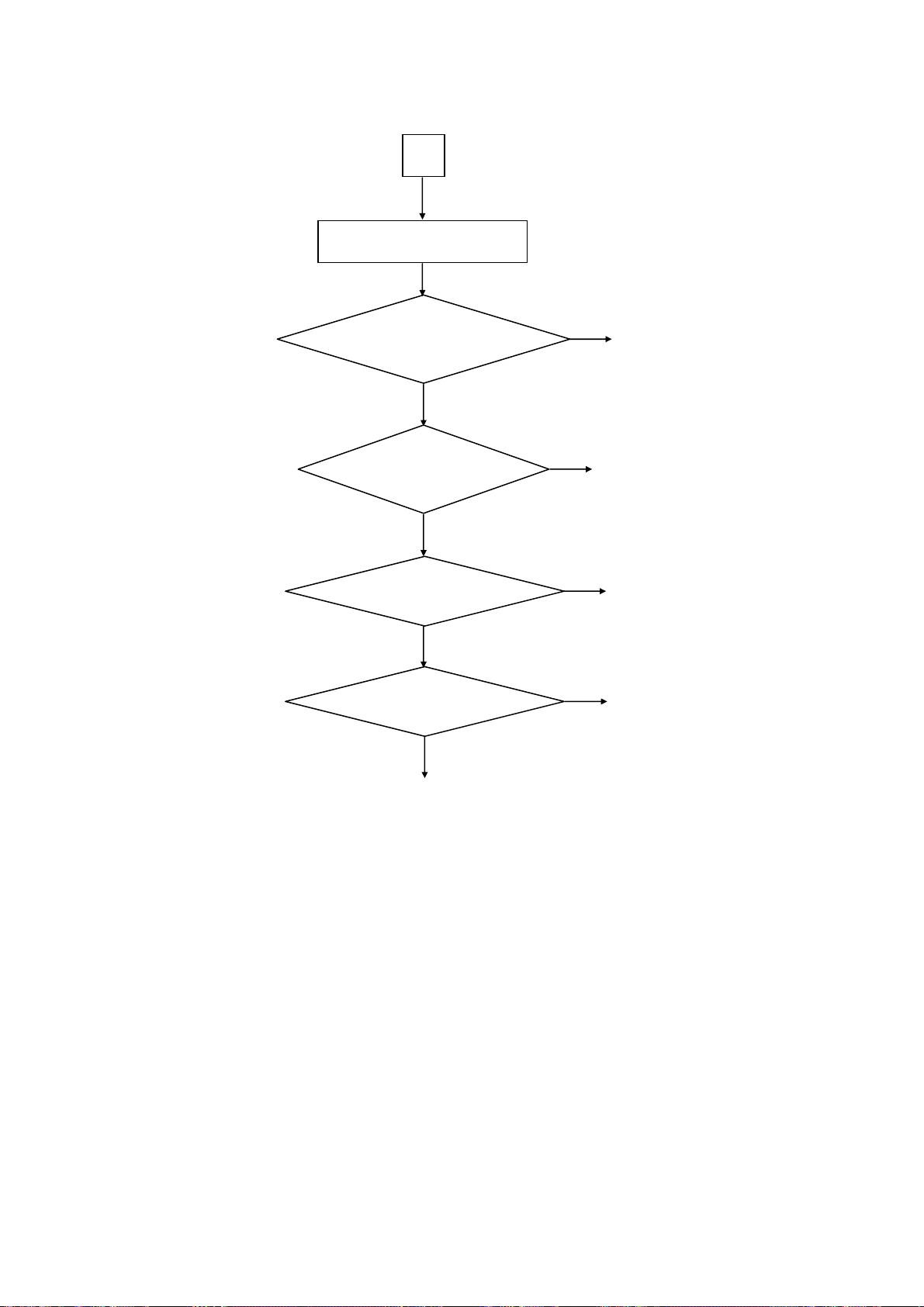
[Picture: RF (analog) troubleshooting]
RF (analog tuner)
e
Are voltages of pin3(+5V)/15(30.7) of
UT01(tuner) of Terminal PCB normal?
Yes
Are waveforms at
pin10 (SCL) /11(SDA) of UT01 (tuner) of
Terminal PCB normal?
Yes
Are waveforms at
pin17 (VIDEO_OUT) of UT01(tuner) of
Terminal PCB normal?
Yes
Are waveforms at
Pin6(CV output) of IM06 of MAIN PCB
normal?
Yes
No
No
Change UT01 of Terminal PCB
Change Terminal PCB
If no improvement,
change MAIN PCB
No
Change UT01 of Terminal PCB
No
Change MAIN PCB
If no improvement,
change Terminal PCB
Change MAIN PCB
18
P50T01U/E P50TP01U/E P42T01U/E P42TP01U/E
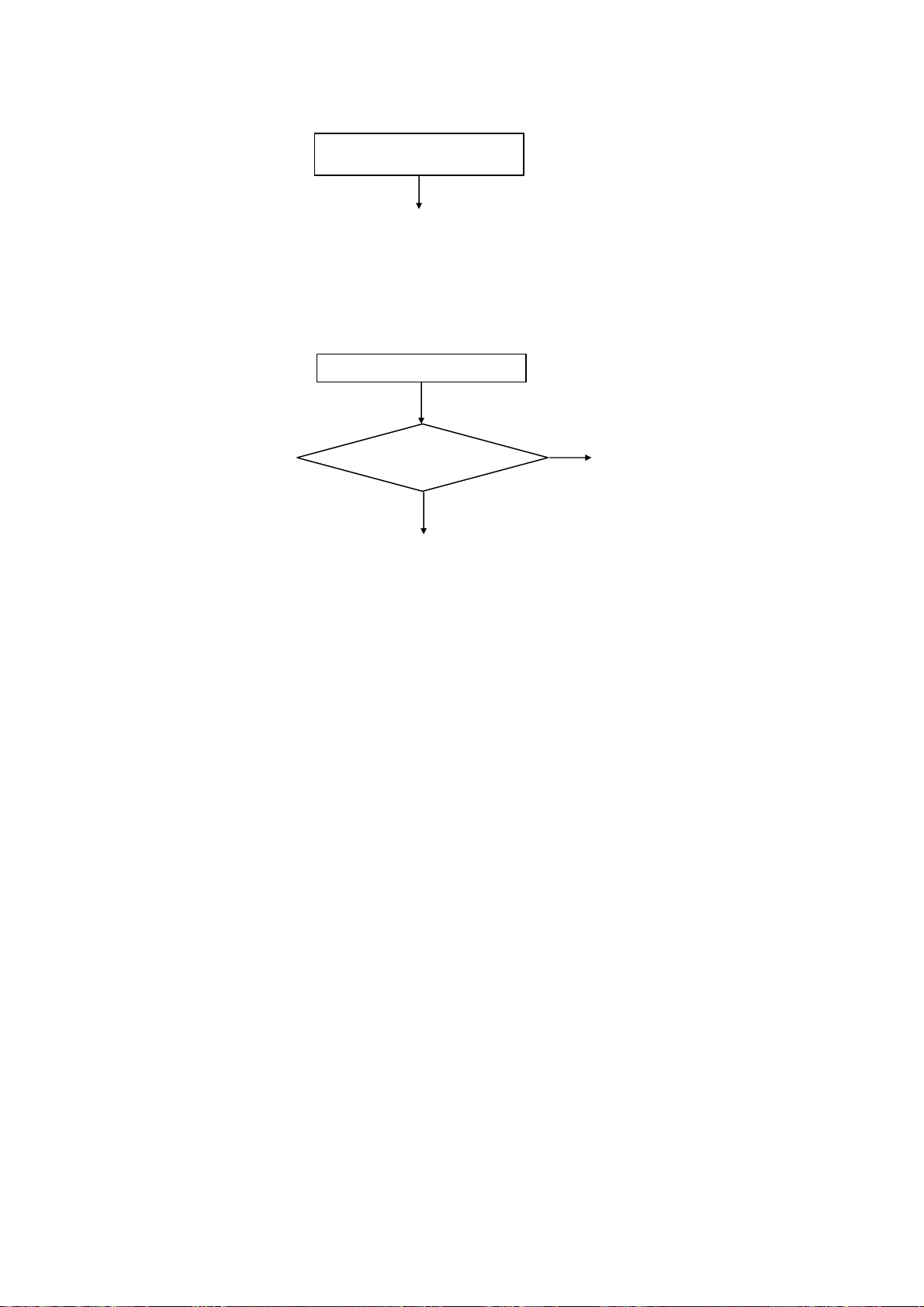
[Picture: Composite & S-video troubleshooting]
f
Composite and S-video
Does a phenomenon appear
if you change a RCA or Mini
DIN cable?
Yes
Are waveforms at
Pin6(CV output) of IM06 of MAIN PCB
normal?
Yes
Change MAIN PCB
[Picture: RGB & Component troubleshooting]
g
RGB
No
Change RCA or Mini DIN cable
No
Change MAIN PCB
If no improvement,
change Terminal PCB
h
Component
Does a phenomenon appear
if you change a SCART
cable?
Yes
Are waveforms at
Pin5(R output), 6(G output),
3(B output) of IM04 of MAIN
PCB normal?
Yes
Change MAIN PCB
No
Change SCART cable
No
Change MAIN PCB
If no improvement,
change Terminal PCB
Does a phenomenon appear
if you change a RCA cable?
Yes
Are waveforms at
Q002 (Pb output)/Q003 (Pr
output)/Q005 (Y output) of MAIN
PCB normal?
Yes
Change MAIN PCB
No
Change RCA cable
No
Change MAIN PCB
If no improvement,
change Terminal PCB
19
P50T01U/E P50TP01U/E P42T01U/E P42TP01U/E
)
[Picture: DTT troubleshooting]
d
DTT
[IWP1] Pin4 (+3.3V)/5(+5.6V)
[IWP2] Pin2/3 (+5.6V)/7/8(+3.3V)
[IW02] Pin2 (+5.6V)/4(+3.3V)
[IW03] Pin1/3 (+2.5V)/5(+1.2V)
[IW04] Pin1/5 (+3.3V)/4(+2.5V)
Check if DW01 of SLOT PCB lights?
No
Are the voltages of IWP1, IWP2, IW02,
IW03, IW04 of SLOT PCB
normal?
Yes
Are the signals of
pin14(SDA)/15(SCL)/17(IF02)/18(IF01) of
UT02 of Terminal PCB
normal?
Yes
Are the signals of
pin37(MCLKo)/35(Mdo0)/27(MoVAL)/26(M
oSYNC)/46(MPEG_PD7) of PW01 of
SLOT PCB normal?
Yes
Are the signals of
pin44(MCLKo)/45(Mdo_0)/46(MoVAL)/48
(MoSYNC)/61(MPEG_PDAT_7) of IW01 of
SLOT PCB normal?
Yes
Change MAIN PCB or SLOT PCB
No
Change SLOT PCB
No
Change UT02 of Terminal PCB
No
No
Change MAIN PCB
If no improvement,
change SLOT PCB or EMP0 (FFC
Change SLOT PCB
cable
.
Yes
Change MAIN PCB
20
P50T01U/E P50TP01U/E P42T01U/E P42TP01U/E
g
[Picture: HDMI troubleshooting]
c
HDMI
HDMI1
HDMI1
pin13/14/16/17/20/21/23/24 of I405 of
Are waveforms at
MAIN PCB normal?
Yes
Change MAIN PCB
Change SD PCB or EMH (FFC cable)
Does a phenomenon appear
if you change a HDMI
cable?
No
Are both inputs abnormal?
No
Which input is abnormal?
No
If no improvement,
chan
e MAIN PCB
Yes
Change HDMI cable
Yes
Change MAIN PCB
HDMI2
HDMI2
Change MAIN PCB
21
P50T01U/E P50TP01U/E P42T01U/E P42TP01U/E
[Sub Picture troubleshooting]
[Teletext troubleshooting]
No picture, no colour or dark
Change MAIN PCB
If no improvement,
change Terminal PCB
No Teletext (analog)
Are the signals of
QM14/15(CV input) of MAIN
PCB normal?
Yes
Change MAIN PCB
If no improvement,
change Terminal PCB
No
Change MAIN PCB
22
P50T01U/E P50TP01U/E P42T01U/E P42TP01U/E
[Sound troubleshooting]
C
Sound is abnormal
RF (analog)/ AV1/2/3/4/5
Are all analog inputs
with no sound?
No
Are all inputs no sound?
No
Which input is abnormal?
HDMI
Same as HDMI (Picture)
troubleshooting
c
Yes
D
DTT
Same as DTT (Picture)
troubleshooting
d
Yes
Change MAIN PCB
If no improvement,
change Terminal PCB
AV1/2/3/4/5
AV1/2/3/4/5
Change Terminal PCB
If no improvement,
change MAIN PCB
Which input is abnormal?
RF (analog tuner)
RF (analog tuner)
E
23

P50T01U/E P50TP01U/E P42T01U/E P42TP01U/E
D
Are signals
to PSPK connector of the
MAIN PCB normal?
No
Change MAIN PCB
If no improvement,
change Terminal PCB
Yes
Change Speaker or ESP1 (cable)
Are the voltages of pin3 (+5V)/15(+30.7V)
of UT01 (tuner) of Terminal PCB normal?
E
Yes
Are the signals of
pin14(SIF_OUT) of UT01(tuner) of
Terminal PCB normal?
Yes
Are the signals of
Pin35(L input)/36(R input) of
IX01 of Terminal PCB
normal?
Yes
Change MAIN PCB
If no improvement,
change Terminal PCB
No
Change UT01 of Terminal PCB
No
Change UT01 of Terminal PCB
No
Change Terminal PCB
[Optical Out (Digital Audio) troubleshooting]
Optical Out (Digital Audio) hasnosound
Are the voltages of pin1/2/3(+5.6V) of
PPM2 connector of MAIN PCB
Are the voltages of pin2 (+5.6V) of
HV01 of Terminal PCB normal?
Change Optical cable
If no improvement,
Change MAIN or Terminal PCB
normal?
Yes
Yes
No
No
Change MAIN PCB
If no improvement,
Check Power Supply Unit
Change Terminal PCB
24

[USB troubleshooting]
P50T01U/E P50TP01U/E P42T01U/E P42TP01U/E
No Picture
Does a phenomenon appear
if you change a USB cable &
EMH (FFC cable)?
No
Change USB cable or EMH (FFC cable)
Yes
Are the voltages of
pin4(+5.6V)/5(+5.0V) of I4U1
of MAIN PCB normal?
No
Change MAIN PCB
Yes
Change SD PCB
If no improvement,
change MAIN PCB
[SD Card troubleshooting] [SWIVEL troubleshooting]
No Picture
SWIVEL does not move
Are the voltages of
pin4/5/6/7(+3.3V) of PSHL
connector of MAIN PCB
normal?
Yes
Change SD PCB
If no improvement,
change MAIN PCB or ESL
(cable)
No
Change MAIN PCB
When the Swivel button
on the remote control,
is "Not Available"
displayed?
Change Terminal PCB or
Yes
A cable is not connected to the swivel stand
or a plug connection is incomplete.
No
Swivel cable
25

P50T01U/E P50TP01U/E P42T01U/E P42TP01U/E
7. Self-Diagnosis Function
PDP panel self-diagnosis function
This function is for a PDP panel failure with no picture.
Panel failure is automatically self-diagnosed.
It is shown by the blinking of the power indicator light (blue).
The next table shows the PDP PCB in which failure most probably would be allocated according to the
number of blinks.
Number of blue blinks
of power indicator light
1 Logic
2 X-SUS
3 Y-SUS, SDM
4 X-SUS, Y-SUS, SDM, PSU
5 ABUS, ADM, PSU
6 ADM temperature
7 ADM temperature
8
[Number of blinks of power indication light]
Ex. 2 blinks
1 sec 1 sec 2 sec OFF Repeat
Presumed failing PCB
of PDP panel
All of above-mentioned
PCBs
SDM: Scan Driver Module
PSU: Power Supply Unit
ABUS: Address Bus Module
ADM: Address Driver Module
Note) SDM is in permanent contact with
glass part.
Note)
1) Main Power switch-off operation cancels the Self-Diagnosis mode.
2) Priority is given when a FAN error occurs (shown by red blinks).
26

P50T01U/E P50TP01U/E P42T01U/E P42TP01U/E
Digital module self-diagnosis function
At main microcomputer startup, hardware (mainly LSI) is checked by a self diagnosis program.
To enter this Self-Diagnosis mode, follow the following steps:
Procedure:
1) Enter Adjustment Mode.
2) Select SELF TEST and press OK button.
3) SELF TEST screen is displayed.
4) Each code is displayed in a SELF TEST screen.
A diagnosis result is displayed with a numerical value to the right side of each code.
Numerical value of 0 indicates normal, all values except 0 are errors.
SELF TEST
SELF TEST
PDP ADJUST MODE
OPTION
MAINTENANCE
SELF TEST
LINE MODE
MMC DEMO
MEMORY INIT
OK
Return
ddb :0
dsm :0
dle :0
dfl :0
dmp :0
ddm :0
dcd :0
drm :0
dpci :0
dlan :0
dsi :0
0 :OK
others :NG
Adjustment Mode screen
SELF TEST screen
A list of codes
code function circuit No. PCB name Error contents
ddb Debug I101 MAIN parameter error, system error
dsm Sub-microcomputer IH04 MAIN system error (-1)
dle LED IH04 MAIN seine general-purpose port lead error, lighting time error, system error
dfl flash I103 MAIN parameter error, device error, system error
dmp MPEG I101 MAIN Video error (2), Audio error (4)
ddm demulti - - error
drm key scan IH04 MAIN system error (-1) / others error (3)
dic IICbus driver I101 MAIN R_SYS_ERROR(-1), DIC_R_DEVICE_ERROR(2)
dvad ADC I101 MAIN system error (-1) /device (I2C) error (2) / driver error (6)
dfc FC I101 MAIN firmware error code, system error
dhdm HDMI I102 MAIN system error (-1) / parameter error (1) / device (I2C) error (2)
dvdc Video decoder I102 MAIN device error, system error
dpdp PDPpanel (for PDP) - PDP panel system error
dldp LCDpanel (for LCD) - LCD panel state impossible of command acceptance, standby, parameter error
dvi Video I101 MAIN device error(firmware error), system error
dvbi VBI slicer I102 MAIN system error
dsl Video Switch I101 MAIN system error
dada Audio amplifier IF07 MAIN parameter error, setting error in suspend, system error
dau Audio I101 MAIN system error
dhpa Headphones amplifier I003 SUB standby, state error
dtu Digital / Analog tuner UT01,UT02 Terminal fail in initialisation, system error
dswv Swivel IH04 MAIN system error (-1) / parameter error (1) /
dmmc MMC - - driver initialisation error, system error
dptp PTP driver I101 MAIN R_SYS_ERROR (-1) other errors (10)
dpq Picture control driver I102, IM01 MAIN,SUB parameter error, system error, suspend error, device error
ddp Display driver I101 MAIN system error
dttc Analog TeleText IR01 SUB device error, system error
dpyc PAL3DY/C Video decoder IM01 SUB device error, system error
dsp Multiplex driver IY01 SUB system error (-1) / I2C communication error (2)
I2C communication error with TAS3103 or TAS5508
sub-microcomputer driver communication error (2) /
initialisation registration not possible error (4)
27

8. Block diagram
P50T01U/E P50TP01U/E P42T01U/E P42TP01U/E
SLOT BOARD
IW02
IWP1
SI-3012KM
TK11133CSC
+3.3V_REG
IW01
XC3S50-5PQG208C
Oberon2
CK53731U
MPEG
SlowBus
JW01
SLOT
+3.3V_REG
IWP2
TPS62040DGQR
+3.3V_DC/DC
IW03
MM3141CNRE
+1.2V_REG
IW04
TK11125CSC
+2.5V_REG
PDP
PANEL
0x30
POWER
UNIT
LVDS
2
1
IC03
IE11
TK11100CS
MM3141DNRE
+9.0V_REG
+1.3V_REG
IG01
IG02
MP2361DK
TPS54210
+1.3V_DC/DC
+3.3V_DC/DC
I305
IC02
MM3141DNRE
TK11125CSC
+1.2V_REG
+2.5V_REG
IA01
IG03
MM3141DNRE
MP2361DK
+1.2V_REG
+1.8V_DC/DC
IC01
MM3141DNRE
+1.2V_REG
IG05
IG04
TK11133CSC
S-80926CNMC
+3.3V_REG
DELAY
IG06
S-80926CNMC
DELAY
CK51856R
UART0
SlowBus
JTAG
PVM
BECKHAM JIG CONNECTOR
IF14
IF16
SI-3012LU
TK11133CSC
+12V_REG
+3.3V_REG
IF17
IF19
TK11133CSC
TK11100CS
+3.3V_REG
+9.0V_REG
IF18
TK11150CSC
+5.0V_REG
IF10
TC7SZ125FU
BUFFER
IF11
TC7SZ125FU
BUFFER
SBY+5.0V
PoWERoFF
AC_SiG
PoWER_1
PoWER_2
PNLoN
+5.6V
+10V
+16V
+12V
CK55478R
CK55478R
AEP_LR
IF04
SN74LVC244APW
SELECTOR
IF05
NJU26040V
AUDIO DSP
IF06
TAS5086DBT
PWM
IF07
TAS5142
D_AMP
ASP_LR
CK08271R
0x3C
CK56382R
0x36
CK56411R
CK56421R
LVDS
I104
RN5VD26C
RESET
CK07203R
I301
EDE5116AHBG
DDR2
CK54091R
I302
EDE5116AHBG
DDR2
CK54091R
I303
EDE5116AHBG
DDR2
CK54091R
I304
EDE5116AHBG
CK54091R
DDR2
I106
CY2305CSXC
BUFFER
I107
TC7SG17FU
BUFFER
IE01
CY22391-03
Clock Generator
PLL_54M
27MHz
PLL_48M
PLL_54.054M
PLL_36.864M
PLL_18.432M
PLL_24.576M
IE03
CY24902
33M_PLL
I101
TC90411AXBG
Seine2_D
CK53761U
USB
LVDS
LVTTL
2
1
CK56141R
0xD8
CK54191R
2
1
MAIN_D0
CLK/SYNC/EN
400K/3.3V
100K/3.3V
SD
IIC_0
IIC_1
IE05
CY24904
DISPLAY_CLOCK
PLL_39.9875M
PLL_74.1758M
PLL_79.7142M
PLL_79.9750M
CK56161R
I801
TK11100CS
+9.0V_REG
I410
TK11150CSC
+5.0V_REG
I407
TK11133CSC
+3.3V_REG
UART0
SlowBus
SD_Y/C
AV4_DET
S/PDiF
UART1
IF03
PCM1808
AUDIO ADC2
ASP_LR
AEP_LR
I408
TK11133CSC
+3.3V_REG
I902
TK11133CSC
+3.3V_REG
I409
TK11125CSC
+2.5V_REG
I802
TK11125CSC
+2.5V_REG
I4U1
TK73650TCB-G
VBUS+5.0V_REG
I803
TK11125CSC
+2.5V_REG
I903
TK11125CSC
+2.5V_REG
I904
TK11115CSC
+1.5V_REG
IE09
TK11130CSC
+3.0V_REG
MAIN BOARD
MAIN AREA
LPF
SD_Y/C
AMP
SEL_LR_S
CK56391R
IF12
ASP_LR
WM8520
AUDIO DAC
CK53922R
IF13
AEP_LR
WM8520
AUDIO DAC
CK53922R
IE10
TK11125CSC
+2.5V_REG
IE11
MM3141DNRE
+1.3V_REG
I901
TC7SZ125FU
BUFFER
CK55478R
I403
PI5C3390QE
BUS SW
CK31863R
IIC
UART1
10MHz
SYNC SEP.
I501
EPM240T100C5N
Nereid
HDMI_AUDIO
LVDS
LVTTL
I102
YAT-050(1080P)
Seine2_A
iiC
I405
CXB1441R
HDMI Switch
Equalizer
IIC
RS-232C
IH01
M306H5FGFP
SUB_MICRO
SYNC SEP.
CK52811U
SD
JTAG
UART0
SlowBus
CK53853U
0xB0
CK53891R
HDMI_3
MTV_AFC
CK56051U
I502
TC7SG17FU
BUFFER
I103
KFG1216U2A
OneNand
656/H/V
CVBS
SY
CY
SC
G
PB
B
PR
R
CVBS
IIC
42MHz
IIC
I406
TC9K111FT
KEY ROM
I402
S-24CS02AFT
EEPROM
IH05
TK11133CSC
+3.3V_REG
SWiVEL
KEY
IR
LED
IH02
BD37A41FVM
RESET
CK51111R
CK55511R
CK52811U
SlowBus
I401
S-24CS02AFT
EEPROM
CK53582R
CK53881R
CK53582R
HDMI_1
J401
J402
HDMI_2
IIC
MAIN BOARD
IM14
TK11133CSC
+3.3V_REG
IM11
TK11133CSC
+3.3V_REG
IIC_1
100K/5V
I002
SN74CB3T3306
3.3V
5V
CK50961R
IIC_1
100K/3.3V
SEL_LR_S
IR04
TC7SZ125FU
BUFFER
SUB
IM13
TK11118CSC
+1.8V_REG
IM12
MM1661JHBE
+1.8V_REG
IM03
TC7SZ125FU
BUFFER
IM04
RGB SELECT
MM1731XVBE
TXT_B
TXT_G
CK38328R
ASP_LR
I004
CD4053BPW
HP SELECT
AREA
CK55478R
656/H/V
H/V
R
B
G
SEL
IM05
CHROMA/BLK
SELELECT
CK55781R
SN74LVC1G3157DCK
B
R
G
TXT_BLK
TXT_R
1.2Vp-p
x0.84
B
G
1.4Vp-p
IIC_1
CVBS
SC/R
B
CVBS/SY/G
SD_Y/C
CVBS/SY/CY
G/CY
B/PB
SC/R/PR
SEL
TXT_R
TXT_G
IR01
TXT_B
TELETEXT
TXT_BLK
H/V
SDA6000
IIC_1
100K/3.3V
DATA
IR02
64Mbit SDRAM
EDS6416GHTA
CK48871U
AEP_LR
CK50121R
IM02
64Mbit SDRAM
EDS6416GHTA
CK48871U
30MHz
LPF
IM01
3D COMB
CXD3815Q
INPUT SIGNAL
CVBS/S-VIDEO
SCART-RGB
TELETEXT-RGB
x0.84
1.4Vp-p
100K/5V
I001
VIDEO SW
AN15867A
x0.64
0x22
0x98
SEL
CK35442R
SC
x0.84
R
1.4Vp-p
CVBS
GROUP
DELAY
CVBS
CK54971U
0x90
6MHz
CK53251U
DATA
ADDRESS
IR03
4Mbit FLASH
S29AL004DTFI01
I003
NJW1109V
H/P AMP
DATA
ADDRESS
CK55971U
IM06
CVBS/SY SELECT
MM1503XN
SEL
x0.59
SC
CVBS
CVBS_OUT_2
CVBS_OUT_1
CVBS/YPBPR_4
RGB_3
RGB_2
S-VIDEO_1
CVBS_3
CVBS_2
CVBS_1
CVBS_5
S-VIDEO_5
IR14
TK11150CSC
+5.0V_REG
IR11
MM1663DHBE
+3.3V_REG
IR13
TK11133CSC
+3.3V_REG
IR12
MP2361DK
+2.5V_DC/DC
CK53591U
0x80
CVBS/SY
CK35442R
SY
CVBS
x0.59
SY
2Vp-p
CVBS
I011
MM1685LHBE
+9.0V_REG
80MHz
x0.59
2Vp-p
IT13
TK11150CSC
+5.0V_REG
IT14
MM1665AHBE
+5.0V_REG
IT11
TK11133CSC
+3.3V_REG
IT12
MM3141CNRE
+1.2V_REG
IIC_0
400K/5V
3.3V 5V
IY02
TC7SZ125FU
S/PDiF
SWIVEL
TERMINAL
BOARD
20.480MHz
MPEG
IT01
CXD1968AR
MAIN
DEMODULATOR
0xD8
IT16
IIC_0
100K/3.3V
TK11150CSC
+5.0V_REG
IIC_0
400K/5V
IY01
A2/NICAM
MSP3415G
CK39261U
0x84
18.432MHz
IY11
MTV_LR
TK11150CSC
+5.0V_REG
HV01
OPT_OUT
IV01
TK86287AM1
Motor Driver
CK50461R
Swivel PCB
SEL_LR_S
RF
UT02
DIGITAL
TUNER
iiC
ENV57M
#02D8F
IFD1/2
IF_AGC
0xC2
IT15
PQ6CU12X2APQ
VT+30V_DC/DC
MTV_AFC
UT01
ANALOG TUNER
SiF
F-E-ENGF7310GF
HC00691
0x86/C0
CVBS
WSS
CVBS
LR_IN
M-OUT
LR_OUT
S-VIDEO
AV1
JX01
IIC_1
IIC_1
100K/5V
100K/5V
ASP_LR
RF
AV4_DET
JIR
IR_OUT
IR
AV4_LR
MTV_LR
IX01
MM1631XJBE
AUDIO SW
CK39891R
0x94
AEP_LR
AV2_LR
AV1_LR
AV5_LR
RGB
WSS
CVBS
LR_IN
M-OUT
AV2
JX02
RF_IN
AV4 I NPUT
DETECTION
AV3_LR
MoNi1_LR
SEL_LR_S
LR_OUT
RS-232C
IY03
MAX202IPW
RS-232C_DRV
RS-232C
EQ00902
JX04
V
L
R
JX05
DVI_LR_IN
DVI_LR
MoNi2_LR
2
1
CVBS
IM04
MM1566AJ
75 DRIVER
CK50431R
CVBS
RGB
WSS
CVBS
M-OUT
AV3
JX03
CK50027R
AV4
Y/V
PB
PR
LR_IN
L
R
LR_OUT
SM016
FILTER
BOARD
AC INLET
SD
BOARD
USB
JU01
USB_IN
USB
CABLE
IH04
SN74LVC1G126DCK
BUFFER
IH01
S-24CS02AFT
EEPROM
CK31863R
CK38325R
SD
IQ01
TC7MBL3245AFK
CK53741R
BUFFER
SD
JQ01
SD_CARD_SLOT
LED
BOARD
IN01
TC7SZ14FU
INVERTOR
SDA
CK38329R
SDA
IIC
SCL
IH05
SN74LVC1G126DCK
BUFFER
CK38329R
SCL
JH01
IIC
HDMI_3
IQ02
TK11133CSC
+3.3V_REG
HDMI_3
IQ03
TC7SG17FU
BUFFER
BLOCK DIAGRAM
28
HN01
IR
KEY
CONTROL BOARD
JNJ2
HEADPHONE
S-VIDEO_1
S
JNJ1
CVBS_5
V
AV5
R
L
SWIVEL
STAND

P50T01U/E P50TP01U/E P42T01U/E P42TP01U/E
9. Connection diagram
AC
FILTER BOARD
POWER
UNIT
CHASSIS METAL
CONNECTOR for AGURI
SLOT BOARD
MAIN BOARD
TERMINAL
BOARD
PDP
PANEL
SPEAKER SPEAKER
SM016
SD
BOARD
USB
CABLE
LED
BOARD
CONNECTOR DIAGRAM
CONTROL
BOARD
SWIVEL
BOARD
SWIVEL
STAND
29

10. Wiring diagrams
(For P50T01U, P50T01E, P50TP01U and P50TP01E)
PURSE LOCK
5.0 (P/N 3749612)
Æ
8.5 (P/N NJ04411)
Æ
11.5 (P/N NJ04401)
Æ
P50T01U/E P50TP01U/E
Ferrite Core Sizes:
Large (P/N GX00667):
NVS05, NVS06, NVS10
Medium (P/N GX00666):
NVS01, NVS02, NVS03, NVS04,
NVS07, NVS08, NVS09, NVS11.
Use 11 in total when 1 includes
a harness product ferrite core.
CAUTION (Connectors)
Do not grip in the direction of the arrow
to avoid defects such as breaking the wire
and/or opening the pin connector part.
This is because the core is thin.
NOTES:
1. This drawing shows connection
and wire styling.
2. This drawing shows the rear
view of the set.
3. Securely lock the lead holder
in place.
4. Cores and SK binders with ( )
round brackets should be
delivered integrated with
harness.
LED Board
Power Unit
Slot Board
Main Board
MAIN Board, EC01 first.
Filter Board
SD BoardControl Board
SM016
WIRING DIAGRAM - 1
30

P50T01U/E P50TP01U/E
(For P50T01U, P50T01E, P50TP01U and P50TP01E)
To Power Unit
To Power Unit
Slot Board
Insert ECN1 (LVDS Cable)
in MAIN Board, EC01 first.
Main Board
To Power Unit
To Power Unit
To Power Unit
To Power Unit
EFAC Preparation:
Secureyl insert Faston of EFAC in the
terminal of the inlet as follows:
To SP
To SP
PS Process
Filter Board
To LED Board
To LED Board
To Control Board
To Control Board
To SP
To SP
NOTES:
1. This drawing shows connection
and wire styling.
2. This drawing shows the rear
view of the set.
3. Securely lock the lead holder
in place.
4. Cores and SK binders with ( )
round brackets should be
delivered integrated with
harness.
SM016
WIRING DIAGRAM - 2
31

(For P42T01U, P42T01E, P42TP01U and P42TP01E)
P42T01U/E P42TP01U/E
PURSE LOCK
5.0 (P/N 3749612)
Æ
8.5 (P/N NJ04411)
Æ
11.5 (P/N NJ04401)
Æ
Ferrite Core Sizes:
Large (P/N GX00667):
NVS05, NVS06, NVS10
Medium (P/N GX00666):
NVS03, NVS04, NVS07
NVS11, NVS12
For FFC (P/N GX00751)
NVS01.
Use 9 in total when 1 includes
a harness product ferrite core.
Name
ECN1
EPU1
ECN6
EPM1
EPM2
ECN23
ECONT
ESL
EC01
CN61
CN64
CN63
PML1
CN68
PSC
PSHL
Connection Point
NameName Board
Power Unit
Power Unit
Power Unit
Power Unit
Power Unit
Power Unit
Main Board
Main Board
CN1
PPU1
CN23
PPM1
PPM2
PPM3
CN6
PSC
PDS
PLS
Board or
Location
Panel Logic
Filter Board
Panel X-SUS
Main Board
Main Board
Main Board
Panel Logic
Control Board
SD Board
LED Board
NOTES:
1. This drawing shows
connection and wire
styling.
2. This drawing shows
the rear view of the
set.
3. Securely lock the
lead holder in place.
4. Cores and SK binders
with ( ) round
brackets should be
delivered integrated
with harness.
LED Board
Filter Board
Power Unit
Control Board
Slot Board
SD Board
Main Board
ESP1
EMP0
EMH
EFAC
PSPK
PA01
P403
---
Main Board
Main Board
Main Board
Inlet
Main Board
---
(Right SP)
---
(Left SP)
PW01
Slot Board
PH01
SD Board
PW01
Filter Board
---
(Chassis Metal)
Logic Board
SM016
WIRING DIAGRAM - 1
32

(For P42T01U, P42T01E, P42TP01U and P42TP01E)
P42T01U/E P42TP01U/E
To Panel
To Power Unit
To Power Unit
To Panel
To Power Unit
To Po w er U n it
Slot Board
EFAC Preparation:
Secureyl insert Faston of EFAC in the
terminal of the inlet as follows:
To SP
To SP
PS Process
Filter Board
To LED Board
To LED Board
Insert ECN1 (LVDS Cable)
in MAIN Board, EC01 first.
Main Board
To Control Board
To Control Board
To SP
To SP
NOTES:
1. This drawing shows connection
and wire styling.
2. This drawing shows the rear
view of the set.
3. Securely lock the lead holder
in place.
4. Cores and SK binders with ( )
round brackets should be
delivered integrated with
harness.
SM016
WIRING DIAGRAM - 2
33

P50T01U/E P50TP01U/E
11. Disassembly diagrams (For P50T01U, P50T01E, P50TP01U and P50TP01E)
SM016
ASSEMBLY DRAWING
34

(For P42T01U, P42T01E, P42TP01U and P42TP01E)
P42T01U/E P42TP01U/E
SM016
ASSEMBLY DRAWING
35

P50T01U/E P50TP01U/E P42T01U/E P42TP01U/E
THE UPDATED PARTS LIST
FOR THIS MODEL IS
AVAILABLE ON ESTA
36

P50T01U/E P50TP01U/E P42T01U/E P42TP01U/E
13. Circuit diagrams
Waveforms
㪠㪤㪇㪈㩿㪚㪭㪙㪪㪀㩷㪉㪈㫇㫀㫅 㪚㪏㪉㪏㩿㪚㪭㪙㪪㪀㩷㪘㪄㪚㪿㫀㫇㩷㫀㫅
㪈㪅㪉㪭
㫇㪄㫇
㪈㪟 㪈㪟
㪠㪤㪇㪈㩿㪪㪄㪰㪀㩷㪉㪈㫇㫀㫅 㪚㪏㪉㪏㩿㪪㪄㪰㪀㩷㪘㪄㪚㪿㫀㫇㩷㫀㫅
㪈㪅㪉㪭
㫇㪄㫇
㪈㪟 㪈㪟
㪠㪤㪇㪈㩿㪪㪄㪚㪀㩷㪊㪇㫇㫀㫅
㪚㪏㪊㪉㩿㪪㪄㪚㪀㩷㪘㪄㪚㪿㫀㫇㩷㫀㫅 㪚㪏㪉㪏㩿㪰㪀㩷㪘㪄㪚㪿㫀㫇㩷㫀㫅
㪇㪅㪎㪭
㪇㪅㪎㪭
㫇㪄㫇
㫇㪄㫇
㪇㪅㪊㪭
㫇㪄㫇
㪈㪟 㪈㪟
㪚㪏㪊㪊㩿㪧㪹㪀㩷㪘㪄㪚㪿㫀㫇㩷㫀㫅 㪚㪏㪊㪌㩿㪧㫉㪀㩷㪘㪄㪚㪿㫀㫇㩷㫀㫅
㪇㪅㪎㪭
㫇㪄㫇
㪈㪟 㪈㪟
㪇㪅㪎㪭
㪇㪅㪎㪭
㫇㪄㫇
㫇㪄㫇
37

P50T01U/E P50TP01U/E P42T01U/E P42TP01U/E
㪠㪤㪇㪈㩿㪩㪀㩷㪈㪌㫇㫀㫅 㪠㪤㪇㪈㩿㪞㪀㩷㪏㫇㫀㫅
㩷㩷㩷㪈㪟 㩷㩷㩷㪈㪟
㪠㪤㪇㪈㩿㪙㪀㩷㪊㫇㫀㫅 㪚㪏㪊㪍㩿㪩㪀㩷㪘㪄㪚㪿㫀㫇㩷㫀㫅
㩷㩷㪈㪟 㪈㪟
㪚㪏㪊㪈㩿㪞㪀㩷㪘㪄㪚㪿㫀㫇㩷㫀㫅 㪚㪏㪊㪋㩿㪙㪀㩷㪘㪄㪚㪿㫀㫇
㩷㫀㫅
㪈㪟 㪈㪟
㪩㪤㪊㪉㩷㩿㪟㪀㩷㪠㪤㪇㪈㩷㫆㫌㫋 㪩㪤㪊㪊㩷㩿㪭㪀㩷㪠㪤㪇㪈㩷㫆㫌㫋
㪈㪟 㪈㪭
㪈㪅㪈㪎㪭
㫇㪄㫇
㪈㪅㪈㪎㪭
㫇㪄㫇
㪈㪅㪍㪎㪭
㫇㪄㫇
㪇㪅㪎㪭
㫇㪄㫇
㪇㪅㪎㪭
㫇㪄㫇
㪇㪅㪎㪭
㫇㪄㫇
㪊㪅㪊㪭
㫇㪄㫇
㪊㪅㪊㪭
㫇㪄㫇
38

P50T01U/E P50TP01U/E P42T01U/E P42TP01U/E
Circuit diagram list
MAIN 1 (P50T01U/P42T01U) ........................ 41
MAIN 2 (P50T01U/P42T01U) ........................ 42
MAIN 3 (P50T01U/P42T01U) ........................ 43
MAIN 4 (P50T01U/P42T01U) ........................ 44
MAIN 5 (P50T01U/P42T01U) ........................ 45
MAIN 6 (P50T01U/P42T01U) ........................ 45
MAIN 7 (P50T01U/P42T01U) ........................ 47
MAIN 8 (P50T01U/P42T01U) ........................ 48
MAIN 9 (P50T01U/P42T01U) ........................ 49
MAIN 10 (P50T01U/P42T01U) ...................... 50
MAIN 11 (P50T01U/P42T01U) ......................51
MAIN 12 (P50T01U/P42T01U) ...................... 52
MAIN 13 (P50T01U/P42T01U) ...................... 53
MAIN 14 (P50T01U/P42T01U) ...................... 54
MAIN 15 (P50T01U/P42T01U) ...................... 55
MAIN 16 (P50T01U/P42T01U) ...................... 56
MAIN 17 (P50T01U/P42T01U) ...................... 57
MAIN 1 (P50T01E/P42T01E) ........................41
MAIN 2 (P50T01E/P42T01E) ........................42
MAIN 3 (P50T01E/P42T01E) ........................43
MAIN 4 (P50T01E/P42T01E) ........................44
MAIN 5 (P50T01E/P42T01E) ........................45
MAIN 6 (P50T01E/P42T01E) ........................46
MAIN 7 (P50T01E/P42T01E) ........................47
MAIN 8 (P50T01E/P42T01E) ........................48
MAIN 9 (P50T01E/P42T01E) ........................49
MAIN 10 (P50T01E/P42T01E) ......................50
MAIN 11 (P50T01E/P42T01E)....................... 51
MAIN 12 (P50T01E/P42T01E) ......................52
MAIN 13 (P50T01E/P42T01E) ......................53
MAIN 14 (P50T01E/P42T01E) ......................54
MAIN 15 (P50T01E/P42T01E) ......................55
MAIN 16 (P50T01E/P42T01E) ......................56
MAIN 17 (P50T01E/P42T01E) ......................57
39

P50T01U/E P50TP01U/E P42T01U/E P42TP01U/E
Circuit diagram list
SUB 1 (P50T01U/P42T01U).......................... 58
SUB 2 (P50T01U/P42T01U).......................... 59
SUB 3 (P50T01U/P42T01U).......................... 60
SUB 4 (P50T01U/P42T01U).......................... 61
SUB 5 (P50T01U/P42T01U).......................... 62
SUB 1 (P50T01E/P42T01E) .......................... 58
SUB 2 (P50T01E/P42T01E) .......................... 59
SUB 3 (P50T01E/P42T01E) .......................... 60
SUB 4 (P50T01E/P42T01E) .......................... 61
SUB 5 (P50T01E/P42T01E) .......................... 62
CONTROL ..................................................... 63
SLOT.............................................................. 64
SD 1............................................................... 65
SD 2............................................................... 66
FILTER/LED/SWIVEL ....................................67
TERMINAL 1 (P50T01U/P42T01U) ...............68
TERMINAL 2 (P50T01U/P42T01U) ...............69
TERMINAL 3 (P50T01U/P42T01U) ...............70
TERMINAL 4 (P50T01U/P42T01U) ...............71
TERMINAL 1 (P50T01E/P42T01E) ...............72
TERMINAL 2 (P50T01E/P42T01E) ...............73
TERMINAL 3 (P50T01E/P42T01E) ...............74
TERMINAL 4 (P50T01E/P42T01E) ...............75
40

P50T01U/E P50TP01U/E P42T01U/E P42TP01U/E
S/T:Schmitt Triger
O/D:Open Drain
p/u:Pull-up
SHEET_5
Nereid
SHEET_5,10,17
SlowBus Address
I101
Seine3/7 Slow Bus
Seine2 2/13 SlowBus
CK53761U
Slow BUS
Address Out
TC90411XBG
Slow BUS
Data I/O
Chip enable
Write enable
Read enable
Clock 66MHz
Byte enable0
Byte enable1
System reset
O/D
S/T
p/u
p/u
S/T
SHEET_10 C/I
SHEET_5 Nereid
SHEET_10 C/I
SHEET_17 FC8
SHEET_10 C/I
SHEET_5 Nereid
SHEET_5,10,17
SlowBus Data
SHEET_5,10,17,18
SlowBus Data
SHEET_18
Virtual connector
SHEET_10 C/I
SHEET_17 FC8
SHEET_5 Nereid
SBADD19
SBADD18
SBADD15
SBADD14
SBADD13
SBADD12
SBADD11
SBADD10
SBADD9
SBADD8
SBADD7
SBADD6
SBADD5
SBADD4
SBADD3
SBADD2
SBADD1
SBADD23
AN3
SBADD22
AM4
SBADD21
AN4
SBADD20
AM5
SBADD19
AN5
SBADD18
AM6
SBADD17
AN6
SBADD16
AM7
SBADD15
AN7
SBADD14
AM8
SBADD13
AN8
SBADD12
AM9
SBADD11
AN9
SBADD10
AM10
SBADD9
AN10
SBADD8
AM11
SBADD7
AN11
SBADD6
AM12
SBADD5
AN12
SBADD4
AK13
SBADD3
AL13
SBADD2
AM13
SBADD1
AN13
SBDAT15
AK5
SBDAT14
AL5
SBDAT13
AK6
SBDAT12
AL6
SBDAT11
AK7
SBDAT10
AL7
SBDAT9
AK8
SBDAT8
AL8
SBDAT7
AK9
SBDAT6
AL9
SBDAT5
AK10
SBDAT4
AL10
SBDAT3
AK11
SBDAT2
AL11
SBDAT1
AK12
SBDAT0
AL12
AJ5
SBCE7_N
AJ6
SBCE6_N
AJ8
SBCE5_N
AJ11
SBCE2_N
AJ12
SBCE1_N
AJ13
SBCE0_N
SBWE_N
AJ7
SBoE_N
AL4
SBCLK
AK14
SBACK_N
AL14
SBBE0_N
AJ10
SBBE1_N
AJ9
SYSRST_N
B2
DBGTDo
D26
DBGTCK
F25
DBGTDi
A26
DBGTMS
E26
DBGTRST_N
F26
SlowBus Byte enable (Pod)
SBBE0_N
SlowBus Ack (Pod)
SBACK_N
SlowBus Read enable
SBoE_N
SlowBus Write enable
SBWE_N
SBCE7_N
SBCE6_N
SBCE5_N
SBCE2_N
SBCE1_N
SBCE0_N
SBDAT7
SBDAT6
SBDAT5
SBDAT4
SBDAT3
SBDAT2
SBDAT1
SBDAT0
SBCLK_5
SBCLK_1
SBCLK_4
SBCLK_2
SBCLK_3
1
*R101
8
47
7
6
5
4
314
215
8
*R102
7
47
6
5
4
3
215
116
8
*R103
7
47
6
5
4
3
215
116
1
R104
2
47
3
4
5
6
710
89
1
R105
2
47
3
4
5
6
710
89
1
3
1
3
5
7
R108
R109
R152
R110
SBBE1_N
Boot Configuration
SBADD18 SBADD19
SBCE6a_N(Oberon2) 0
SBCE6b_N(Nereid) 1
SBCE6c_N(FC8) 0
SBCE6d_N(Beckham) 1
BOARD VISION
7
8
CLK4
(2bit)
share pin mode
SBADD14:Reserved(pull down)
1
34
2
2010
10K
R117
10K
R116
00101 : mode 5
10K
1
1
34
2
2
R115
10k
1010
R114
SBADD23
SBADD22
SBADD21
SBADD20
SBADD19
SBADD18
SBADD17
SBADD16
SBADD15
SBADD14
SBADD13
SBADD12
SBADD11
SBADD10
SBADD9
SBADD8
SBADD7
SBADD6
SBADD5
SBADD4
SBADD3
SBADD2
SBADD1
SBDAT15
SBDAT14
SBDAT13
SBDAT12
SBDAT11
SBDAT10
SBDAT9
SBDAT8
SBDAT7
SBDAT6
SBDAT5
SBDAT4
SBDAT3
SBDAT2
SBDAT1
SBDAT0
DBGTRST_N
SBCE7_N
SBCE5_N
SBCE2_N
SBCE1_N
SBCE0_N
DBGTDo
DBGTCK
DBGTDi
DBGTMS
SBADD10:NAND Width bit 16bit
SBADD13:Timer Interrupt Enable
SBADD3 L:DDR Width bit 64bit
H:DDR Width bit 32bit
10K
10K
10K
10K
10K
10K
5
7
8
R121
R120
*R123
*R122
47
R112
0
R197
R198
R143
8
R145
7
R144
6
VDD
*R146
5
1005
C107
0.1/16
6
*R149
*R150
10K
R119
0
33
22
22
22
Reserved
(pull down)
GND1
16
9
10
11
12
13
9
10
11
12
13
14
9
10
11
12
13
14
16
15
14
13
12
11
16
15
14
13
12
11
R106
47
1010
2
4
2
4
6
8
R107
47
2010
47
47
68
47
1
34
5
7
2
8
6
10K
2010
R118
R140
10K
8REN
SlowBus CLK
SBCLK:original CLK
SBCLK_0:(OneNand Flash)
SBCLK_1:(Oberon2)
SBCLK_2:(FC8)
SBCLK_3:(Nereid)
SBCLK_4:(Seine2D PTS)
SBCLK_5:(Tenko4)
SBADD5:Reserved(PullUp)
SBADD6:Reserved(PullUp)
SBADD1:PCI Mode Host
SBADD2:PCI Arbiter Internal
SBADD4:DDR Data Rate 333MHz
SBADD9:SBCLK Speed 66MHz
1
1
3
56
7
2
2
8
4
10K
10K
2010
R125
R124
6
10
4
1
7
9
3
2
58
R113
1
2
4
3
6
5
8
7
2010
10K
SBADD7:Slow Bus Ch0 Boot
SBADD8:Slow Bus Ch0 Boot
3
56
4
2010
Zero_Delay_Buf.
I106
REF
CLKOUT
1
*R141
CLK2
2
33
*R142
CLK1
3
22
GND CLK3
4
CK56181R
CS6649AMT
GND1
+3.3V
0
0
1
1
OneNand
I103
KFG1216U2A-DIB6
SBADD1 SBDAT0
SBADD2
SBADD3
SBADD4
SBADD5
SBADD6
SBADD7
SBADD8
SBADD9
SBADD10
SBADD11
SBADD12
SBADD13
SBADD14
SBADD15
SBADD16
R126 47
R127 47
R128
R129
R131
10K
GND1
G2
i
A0
G3
i
A1
H4
i
A2
H5
i
A3
H2
i
A4
H3
i
A5
G6
i
A6
F4
i
A7
F6
i
A8
E6
i
A9
G5
i
A10
F5
i
A11
D2
i
A12
F2
i
A13
F1
i
A14
D4
i
A15
A1
i
WE_N
B4
i
OE_N
E2
i
CE_N
0
F3
i
AVD_N
A2
i
RP_N
10K
G1
o
INT
H1
o
RDY
E1
i
CLK
NC
NC-E4
E4
NC
NC-E5
E5
NC
NC-G4
G4
NC
NC-H6
47
H6
R130
NC
NC-N1
N1
NC
NC-N2
N2
NC
NC-N3
N3
NC
NC-N4
N4
NC
NC-N5
N5
NC
NC-N6
N6
NC
NC-N7
N7
NC
NC-N8
N8
NC
NC-N9
N9
NC
NC-N10
N10
NC
NC-N11
N11
NC
NC-N12
N12
NC
NC-N13
N13
NC-N14
N14
TC7SG17FU
VCC
5
1005
C108
0.1/16
4
i/o
i/o
i/o
i/o
i/o
i/o
i/o
i/o
i/o
i/o
i/o
i/o
i/o
i/o
i/o
i/o
PoWER
PoWER
PoWER
PoWER
NC-N15
NC-N16
NC-N17
NC-N18
NC-N19
NC-N20
NC-N21
NC-N22
NC-N23
NC-N24
NC-N25
NC-N26
NC-N27
NC-N28
NC-N29
NC-N30
NC-N31
I107
CK55511R
DQ10
DQ11
DQ12
DQ13
DQ14
DQ15
Vcc-Core
Vcc-io
Vss-A4
Vss-A5
NC
IN
GNDOUT
SlowBus Chip Enable (Beckham Nor Flash)
SlowBus Chip Enable (Vecky)
CENoR_N
CEoNB_N
SBCE6d_N
PNLRST
SHEET_5 Nereid
PVM
D3
DQ0
SBDAT1
B3
DQ1
SBDAT2
E3
DQ2
SBDAT3
C5
DQ3
SBDAT4
C2
DQ4
SBDAT5
D5
DQ5
SBDAT6
D6
DQ6
SBDAT7
C1
DQ7
SBDAT8
B2
DQ8
SBDAT9
B5
DQ9
SBDAT10
C4
SBDAT11
C3
SBDAT12
B1
SBDAT13
A6
SBDAT14
A3
SBDAT15
D1
+3.3V
B6
C6
A4
1005
C101
C102
0.1/16
A5
GND1
3
N15
NC
N16
NC
NC
NC
NC
NC
NC
NC
NC
NC
NC
NC
NC
NC
NC
NC
NCNC
2
RB491D
N17
N18
N19
N20
N21
N22
N23
N24
N25
N26
N27
N28
N29
N30
N31
1
R135
2
47
3
GND1
C104
0.1/16
GND1 GND1
10K
R148
1005
0.1/16
0
D103
R199
1
I104
R3112N261C-TR-FA
OUT
1
2
VDD
6.9mSec
3
GND NC
CK57423R
1005
Voltage Detector
(CMOS TYPE)
SlowBus Chip Enable
(Beckham Onenand)
Debug connector
of Beckham
Debug Port
RESET IC
D101
CD
5
SDS511
C103
0.0047
4
for Beckham OneNand
R132
1.0K
WR-120VS(H30)
1
PG_+5.6V
3
5
7
9
Reserved
BECK_ARi
11 12
SBCE6d_N
13 14
SBCE2_N
15 16
SBCE5_N
17 18
19 20
21 22
SBCE7_N
23 24
25 26
CEoNB_N
27 28
CENoR_N
29 30
SBCE0_N
31 32
SBCE1_N
33 34
35 36
SBDAT0
37 38
SBDAT1
39 40
SBDAT2
41 42
SBDAT3
43 44
45 46
SBDAT5
47 48
SBDAT6
49 50
SBDAT7
51 52
SBADD1
53 54
SBADD2
55 56
SBADD3
57 58
SBADD4 SBADD16
59 60
SBADD5
61 62
SBADD6
63 64
SBADD7
65 66
SBADD8
67 68
SBADD9
69 70
SBADD10
71 72
SBADD11
73 74
SBADD12
75 76
EXTRST_N
77 78
DBGTDi
79 80
DBGTDo
81 82
DBGTMS
83 84
DBGTRST_N
85 86
EJTAGRST_N
87 88
89 90
GND
DBGTCK
91 92
93 94
GND
S_TXD
95 96
S_RXD
97 98
S_RESET
99 100
S_BUSY
101 102
SYSRST_N
103 104
UACTS0_N
105 106
UARTS0_N
107 108
UARXD0
109 110
UATXD0
111 112
113 114
115 116
SBY+5.0V
117 118
GND
119 120
D+3.3V
R136
PNL_RX
PNL_TX
PNL_MoDE
PNL_P2
PNL_P0
PNL_CLK
PNLRST
CEoNM_N
SBADD10
SBDAT8
SBDAT9
SBDAT10
SBDAT11
SBDAT12SBDAT4
SBDAT13
SBDAT14
SBDAT15
SBADD13
SBADD14
SBADD15
SBADD17
SBADD18
SBADD19
SBADD20
SBADD21
SBADD22
SBADD23
WR_ARi
FWP_N
SYSRST_N
SBoE_N
SBWE_N
SAOE_N
PNL_ARi
BDSEL1
BDSEL2
S_SCLK
S_VPP
S_CNVSS
J_TDi
J_TMS
J_TDo
J_TCK
D+3.3V
SlowBus Chip Enable (Main Onenand)
D102
1.0K
SDS511
C105
0.0015
GND
GND
GND
GND
GND
GND
GND
GND
GND
Beckham Manual Reset
RN5VD26C
Cd
5
4
2
4
6
8
10
for Beckham NoR
GND1
JTAG Reset
I105
1mSec
CK07203R
Voltage Detector
Beckham OneNand FBUSY
TP007
R147
10K
PVM72
OUT
1
2
VDD
GNDNC
3
C106
R139
0.1/16
47
1005
System Reset
PNL_RX
PNL_TX
PNL_MoDE
PNL_P2
PNL_P0
PNL_CLK
BDSEL1
BDSEL2
J_TDi
J_TMS
J_TDo
J_TCK
SYSRST_N
EJTAGRST_N
EXTRST_N
CEoNM_N
WDTRST_N
BECK_ARi
FWP_N
UATXD0
UARXD0
UARTS0_N
UACTS0_N
FRDY
S_SCLK
S_VPP
S_CNVSS
S_BUSY
S_RESET
S_RXD
S_TXD
SBY+5.0V
D+3.3V
PG_+5.6V
PLL+3.0V
PLLoE_N
SHEET_11
PDP_Micro Writing
SHEET_5
Nereid
SHEET_2
Seine2_D
SHEET_15
Sub Micro
SHEET_14 Power
SHEET_12 PLL
Parts marked with hatching are
not mounted in this model.
SM016
MAIN BOARD CIRCUIT - SHEET 1
41

INT
UART
SD
CARD
IIC
USB
(SC1VCCEN_N)
(SC1RST)
(SC1C7IO)
(SC1DET_N)
(SC1CLK)
(MDMRXD)
(MDMRTS_N)
(MDMTXD)
(MDMCTS_N)
1/0 = WP oN/oFF
1/0 = not det/det
I2C ch0
I2C ch1
I2C ch2
USB CLK 48MHz
USB data
1/0 = USB Power on/off
USB data
1/0 = OC det/not det
USB2.0 EXT Registor
USB2.0 monitor out
Common Power
Transceiver Power
Transceiver Power
USB2.0 GND
ACCLK: Don't use
ACDATA: Don't use
S/T:Schmitt Triger
O/D:Open Drain
p/u:Pull-up
*I101
TC90411XBG
CK53761U
Peripheral
O/D & S/T
O/D & S/T
O/D & S/T
O/D & S/T
O/D & S/T
O/D & S/T
p/d
p/d
p/d
p/d
p/d
p/d
p/d
p/d
p/u
p/u
O/D
p/u
p/u
p/u
p/u
O/D & p/u
p/u
p/u
p/u
p/u
O/D
p/u
p/u
Japan:IC cardJapan modem
p/u
p/u
O/D
p/u
p/u
p/u
p/u
p/u
p/u
p/u
p/u
p/u
p/u
Seine2
UARTS0_N
UACTS0_N
UA0EXCLK
UARTS1_N
UACTS1_N
UA1EXCLK
UARTS2_N
UACTS2_N
UA2EXCLK
UARTS3_N
UACTS3_N
UA3EXCLK
SCCLK48M
(iN)
DMAREQ0
(iN)
DMAACK0
(oUT)
(oUT)
(i/o)
(i/o)
(i/o)
(i/o)
(i/o)
(iN)
(iN)
i2CDATA0
i2CDATA1
i2CDATA2
(iN)
USBCLKXo
(i/o)
(i/o)
(oUT)
(iN)
USBoVERC
(-)
USBREXT
(oUT)
USBTEST
AVDUSBCM
AVDUSBTRB0
AVDUSBTRA0
GND-AH18
GND-AH17
GND-AH16
GND-AH15
iRQ7
iRQ6
iRQ5
iRQ4
iRQ3
iRQ2
iRQ1
iRQ0
UARXD0
UATXD0
UARXD1
UATXD1
UARXD2
UATXD2
UARXD3
UATXD3
SDCLK
SDCMD
SDDAT3
SDDAT2
SDDAT1
SDDAT0
SDWP
SDCD
i2CCLK0
i2CCLK1
i2CCLK2
USB0DP
USB0DM
USBPW
ACCLK
ACDATA
BL0PWM
BL1PWM
10/13
W5
AA5
AB5
AC5
AD5
A23
B23
C23
D23
E23
A24
B24
C24
D24
E24
D21
B20
E21
A20
C21
D22
A21
E22
A22
B22
C20
D20
A19
B16
A16
D18
E19
B17
C17
C18
A17
B18
A18
D19
E20
C19
B19
AL15
AN15
AN14
AM14
AJ14
AJ15
AM15
AK15
AJ16
AK16
AH18
AH17
AH16
AH15
D11
D15
P50T01U/E P50TP01U/E P42T01U/E P42TP01U/E
SHEET_14 Power
9
13
15
121110
14
10K
*R201
116
3
5
2
7
8
6
4
V4
V5
Y5
*R210
10K
10K
*R211
*R212
10K
10K
*R213
*R214
10K
10K
*R215
10K
*R216
10K
*R217
*R248 47
*R249 47
7
5
3
1
150
48M-2
*R265
0
1010
*R261
3.3K-1%
1005
0.1/16
48M-1
47
47
8
6
4
2
1.8K
*R220
1.8K
*R221
5.6K
*R222
5.6K
*R223
4.7K
*R224
4.7K
*R225
GND1
TP_DMAREQ0
TP_DMAACK0
*R251
*R252
*R253
47
2010
220
*R254
1
2
3
4
1010
*R255
1
2
3
4
1010
*R256
1
2
3
4
1010
150
1
2
3
4
*R260
180-1%
USBTST
2125
10/10
*C201
*C202
C1
ACCLK
ACDATA
C2
BL1PWM
HiNT1
PoD_iRQ_N
iRQ_Xcode2
TUNiRQ3_N
TUNiRQ2_N
Tenko0
TUNiRQ1_N
TUNiRQ0_N
UARTS3_N
UACTS3_N
UARXD0
UATXD0
UARTS0_N
UACTS0_N
UARXD1
UARTS1_N
UATXD1
UACTS1_N
UARXD3
UATXD3
PLL_48M_1
PLL_48M_2
SDCLK
SDCMD
SDDAT3
SDDAT2
SDDAT1
SDDAT0
SDWP
SDCD
ch0(400K) 3.3V
SDA0_3V_400
SCL0_3V_400
ch1(100K) 3.3V
SDA1_3V_100
SCL1_3V_100
ch2(100K) 3.3V
SDA2_3V_100
SCL2_3V_100
USB0DP
USB0DM
USBPW
USBoVERC
BL0PWM
Parts marked with hatching are
not mounted in this model.
SHEET_9 Seine2_A
SHEET_10 C/I
SHEET_16 Virtual connector
SHEET_1 Beckham
SHEET_5 Nereid
SHEET_1 Beckham
SHEET_15 Sub Micro
SHEET_5 Nereid
SHEET_16 Virtual connector
SHEET_12 PLL
SHEET_5 N ereid
SHEET_16 Virtual connector
SHEET_9 S eine2_A
SHEET_12 PLL
SHEET_16 Virtual connector
SHEET_9 S eine2_A
SHEET_13
SHEET_16 Virtual connector
SHEET_17 FC8
SHEET_18 Virtual connector
SHEET_11 Panel
SHEET_16 Virtual connector
SHEET_4 P 403 (HDMI con)
SHEET_16 Virtual connector
SHEET_11 Panel
1
*R257
1010
0
2
43
*I101
TC90411XBG
CK53761U
Seine2
Pio
p/u nashi
p/u nashi
p/u nashi
p/u nashi
p/u nashi
p/u nashi
p/u nashi
p/u+S/T
p/u nashi
p/u nashi
p/u nashi
p/u nashi
p/u nashi
p/u nashi
p/u nashi
Pio58
Pio49
p/u
Pio48
p/u
Pio47
p/u
Pio46
p/u
Pio45
p/u
p/u
Pio44
p/u
Pio43
Pio42
p/u
Pio41
p/u
Pio40
p/u
Pio39
p/u
Pio38
p/u
Pio37
p/u
Pio36
p/u
Pio35
p/u
p/u
Pio34
p/u
Pio33
Pio32
p/u
Pio31
p/u
Pio30
p/u
Pio29
p/u
Pio28
Pio27
Pio26
Pio25
Pio24
Pio23
Pio22
Pio21
p/d
p/d
Pio20
Pio6
Pio5
Pio4
Pio3
Pio2
Pio1
Pio0
11/13
C22
AK21
AL21
AK22
AL22
AK23
AL23
AK24
AM20
AN20
AM21
AN21
AM22
AN22
AM23
AM16
AN16
AM17
AN17
AM18
AN18
AM19
E18
D16
C15
D17
B15
C16
A15
U4
V3
B21
F24
A25
B25
C25
D25
E25
10K
*R226
2010
2
*R275
1
4
3
7
834
6
5
GND1
56
1010
8
7
1
2
*R274
1
3
10K
*R273
*R276
47
*R277
2010
1.0K
*R278
*R279
*R227
1
3
5
7
1
5
7
3
1
3
1
3
5
7
*R281
1
3
1
3
1010
2
4
1010
47
2
*R270
4
47
6
2010
8
47
47
2
*R271
6
47
8
2010
4
*R280
2
47
4
1010
2
*R272
4
47
6
8
2010
47
2
4
47
2
4
10k
D+3.3V
SC0VCCEN_N
SC0RST
SC0C7io
SC0DET_N
UEI I/F
UEi_RXD_N
UEi_TXD_N
oB_CoNF_PRoG
oB_CoNF_DoNE
oB_CoNF_iNiT
AUDioAMP_SD
SPDiF_MUTE
HP_SEL
DE-EMPHASiS_2
DE-EMPHASiS_1
BL_iNST
BL_oN
RAiKo_N
LVDS_SEL
TK_nCoNFIG
TK_CoNF_DoNE
TK_nSTATUS
ADTRG
SYNCDET1_N
SYNCDET0_N
STC_SEL1
STC_SEL0
PNLoN
BiCCLKCNG
iRB_RST_N
ANT_SEL
LNBSHoRT
MDM_RST_N
TUAD_SEL_S
TUAD_SEL_M
MDM_DCD_N
LANiNT_N
iLink_iNT_N
AV4_DET
FUNC2
FUNC1
Beckham
BECK_ARi
OneNand
FRDY
Beckham
FWP_N
SHEET_16
Virtula connector
SHEET_10
C/I I/F
SHEET_13
Audio
SHEET_11
Panel
SHEET_18
Virtual connector
SHEET_15
Sub Micro
SHEET_12
PLL
SHEET_11
Panel
SHEET_14
Power
SHEET_16
Virtual connector
SHEET_16
Virtual connector
SHEET_1 Beckham
SM016
MAIN BOARD CIRCUIT - SHEET 2
42

P50T01U/E P50TP01U/E P42T01U/E P42TP01U/E
Parts marked with hatching are
not mounted in this model.
Power
D+1.8V
D+3.3V
C3C0
1.0/6.3
GND1
5
VOUT
I305
CK54332R
VDD
1
GND
2
TCFG3528
C3C1
C3A9
100/ 4
4
C3C2
MM3141DNRE
CE NC
3
0.1/16
TF
GND1
4.7/6.3
SHEET_14
1.3V
0.1/16
C301
0.1/16
C302
C303 0.1/16
0.1/16
C304
0.1/16
C305
0.1/16
C306
0.1/16
C307
0.1/16
C308
0.1/16
C309
0.1/16
C310
0.1/16
C311
0.1/16
C312
0.1/16
C313
0.1/16
C314
0.1/16
C315
0.1/16
C316
C317 0.1/16
0.1/16
C318
0.1/16
C319
C320 0.1/16
0.1/16
C321
0.1/16
C322
C323 0.1/16
C324 0.1/16
0.1/16
C325
0.1/16
C326
0.1/16
C327
0.1/16
C328
0.1/16
C329
0.1/16
C330
0.1/16
C331
0.1/16
C332
0.1/16
C333
0.1/16
C334
0.1/16
C335
C336
1005
1 005
1 005
1 005
1 005
1 005
1 005
1 005
1005
1 005
1 005
1 005
1 005
1 005
1 005
1 005
1 005
1 005
1 005
1 005
1 005
1 005
1 005
1 005
1 005
1 005
1 005
1 005
1 005
1 005
1 005
1 005
1 005
1 005
1 005
0.1/16
C337
C338
C339
C340
C3C3
GND1
1005
R340
2.7K
R302
R301
R303
R341
0.1/16
0.1/16
0.1/16
0.1/16
0.1/16
82
680
1.0K-1%
430-1%
1 005
1 005
1 005
1 005
1 005
R339
2.7K
GND1
W28
AA30
AC28
AC30
AC33
AE29
AE32
AG28
AG31
AJ28
AJ33
AK27
AK31
AL30
AL31
AM26
AM33
AN29
W29
AD28
AH27
W30
W32
AA28
AA29
AA31
AB31
AD29
AD30
AD31
AE28
AE33
AF30
AF33
AH28
AH31
AJ27
AJ30
AK28
AK29
AL26
AL28
AL32
AL33
AM31
AN27
AN32
AN33
A29
B26
B33
C30
C31
D27
D31
E28
E33
G28
H30
H33
J30
K32
L28
M31
N30
P33
R28
R31
U33
V30
Y33
V29
V28
F27
K28
A27
A32
A33
B31
C26
C28
C32
C33
D28
D29
E27
E30
F28
F31
G31
J28
J29
J31
K29
K33
L30
L33
N28
N29
N31
N32
P30
R32
T30
U28
U31
V32
Y30
1/13
VDD18-A29
DDR IO VDD(1.8)
VDD18-B26
VDD18-B33
VDD18-C30
VDD18-C31
VDD18-D27
VDD18-D31
VDD18-E28
VDD18-E33
VDD18-G28
VDD18-H30
VDD18-H33
VDD18-J30
VDD18-K32
VDD18-L28
VDD18-M31
VDD18-N30
VDD18-P33
VDD18-R28
VDD18-R31
VDD18-U33
VDD18-V30
VDD18-W28
VDD18-Y33
VDD18-AA30
VDD18-AC28
VDD18-AC30
VDD18-AC33
VDD18-AE29
VDD18-AE32
VDD18-AG28
VDD18-AG31
VDD18-AJ28
VDD18-AJ33
VDD18-AK27
VDD18-AK31
VDD18-AL30
VDD18-AL31
VDD18-AM26
VDD18-AM33
VDD18-AN29
Analog VDD(1.2V)
VDA12
Output inpedance reference resistance
RDRV
ODT reference resistance
RoDT
DVREF3
DQ reference voltage 3
DQ reference voltage 2
DVREF2
DQ reference voltage 1
DVREF1
DQ reference voltage 0
DVREF0
proofread reference voltage
DRVCAL
GND1-A27
GND
GND1-A32
GND1-A33
GND1-B31
GND1-C26
GND1-C28
GND1-C32
GND1-C33
GND1-D28
GND1-D29
GND1-E27
GND1-E30
GND1-F28
GND1-F31
GND1-G31
GND1-J28
GND1-J29
GND1-J31
GND1-K29
GND1-K33
GND1-L30
GND1-L33
GND1-N28
GND1-N29
GND1-N31
GND1-N32
GND1-P30
GND1-R32
GND1-T30
GND1-U28
GND1-U31
GND1-V32
GND1-W32
GND1-Y30
GND1-AA28
GND1-AA29
GND1-AA31
GND1-AB31
GND1-AD29
GND1-AD30
GND1-AD31
GND1-AE28
GND1-AE33
GND1-AF30
GND1-AF33
GND1-AH28
GND1-AH31
GND1-AJ27
GND1-AJ30
GND1-AK28
GND1-AK29
GND1-AL26
GND1-AL28
GND1-AL32
GND1-AL33
GND1-AM31
GND1-AN27
GND1-AN32
GND1-AN33
I101
TC90411XBG
Seine2
CK53761U
Data Pass 63
Data Pass 0
Address 12
Address 0
SDRAM clock
SDRAM clock reverse
Clock enable
chipset 1(high 32bit)
chipset 0(low 32bit)
row-address strop
column-address strop
Write enable
Bank-address select 2
Bank-address select 1
Bank-address select 0
I/O mask 7
I/O mask 6
Data strop 7
Data strop 6
I/O mask 5
I/O mask 4
Data strop 5
Data strop 4
I/O mask 3
I/O mask 2
Data strop 3
Data strop 2
I/O mask 1
I/O mask 0
Data strop 1
Data strop 0
ODT pin(high 32bit)
ODT pin(low 32bit)
DDR2
DDRDB63
DDRDB62
DDRDB61
DDRDB60
DDRDB59
DDRDB58
DDRDB57
DDRDB56
DDRDB55
DDRDB54
DDRDB53
DDRDB52
DDRDB51
DDRDB50
DDRDB49
DDRDB48
DDRDB47
DDRDB46
DDRDB45
DDRDB44
DDRDB43
DDRDB42
DDRDB41
DDRDB40
DDRDB39
DDRDB38
DDRDB37
DDRDB36
DDRDB35
DDRDB34
DDRDB33
DDRDB32
DDRDB31
DDRDB30
DDRDB29
DDRDB28
DDRDB27
DDRDB26
DDRDB25
DDRDB24
DDRDB23
DDRDB22
DDRDB21
DDRDB20
DDRDB19
DDRDB18
DDRDB17
DDRDB16
DDRDB15
DDRDB14
DDRDB13
DDRDB12
DDRDB11
DDRDB10
DDRDB09
DDRDB08
DDRDB07
DDRDB06
DDRDB05
DDRDB04
DDRDB03
DDRDB02
DDRDB01
DDRDB00
DDRAD12
DDRAD11
DDRAD10
DDRAD09
DDRAD08
DDRAD07
DDRAD06
DDRAD05
DDRAD04
DDRAD03
DDRAD02
DDRAD01
DDRAD00
DDRCLK
DDRBCLK
DDRCKE
DDRCS1
DDRCS0
DDRRAS_N
DDRCAS_N
DDRWE_N
DDRBA2
DDRBA1
DDRBA0
DDRDM7
DDRDM6
DDRDQS7
DDRDQS6
DDRDM5
DDRDM4
DDRDQS5
DDRDQS4
DDRDM3
DDRDM2
DDRDQS3
DDRDQS2
DDRDM1
DDRDM0
DDRDQS1
DDRDQS0
oDT1
oDT0
F33
F32
E32
E31
F30
F29
D33
D32
B27
C27
A28
B28
B29
C29
A30
B30
M33
M32
M30
M29
L32
L31
L29
M28
G29
G30
H28
H29
G32
G33
H31
H32
AG29
AG30
AF28
AF29
AG32
AG33
AF31
AF32
AB33
AB32
AB30
AB29
AC32
AC31
AC29
AB28
AM27
AL27
AN28
AM28
AM29
AL29
AN30
AM30
AH33
AH32
AJ32
AJ31
AH30
AH29
AK33
AK32
P28
N33
T29
R29
P31
P29
R33
T28
P32
R30
T32
T33
T31
W33
V33
Y28
V31
W31
Y31
Y32
Y29
U32
U30
U29
B32
A31
D30
E29
J33
J32
K31
K30
AD32
AD33
AE30
AE31
AN31
AM32
AJ29
AK30
AA33
AA32
7
8
5
6
4
3
2
116
1
2
3
4
5
6
7810
7
8
6
5
1
2
3
413
4
3
6
5
1
2
8
710
3
4
5
6
8
7
1
215
1
2
3
4
8
7
6
512
8
7
6
5
4
3
2
116
2
1
4
3
5
6
7810
7
5
1
3
1
2
3
4
5
6
8
710
R314
R315
R316
R317
1
3
R319
R320
R321
R322
R323
R324
R351
7
*R325
34
22
5
1
7
*R326
34
22
5
1
7
R327
34
5
22
1
7
R328
34
22
5
1
1
3
10K
R352
R353
GND1
10
9
*R304
12
47
11
13
14
15
16
15
*R305
14
47
13
12
11
9
10
9
*R306
11
47
12
16
15
14
13
14
*R307
11
12
47
16
15
9
14
13
R308
12
11
47
9
10
16
16
15
R309
14
47
13
9
10
11
9
10
R310
11
47
12
13
14
15
15
16
R311
13
14
47
12
11
9
8
6
R312
2
22
4
16
15
R313
14
22
13
12
11
9
22
0
0
22
2
R318
1010
33
4
22
22
22
22
22
22
10K
8
6
2
8
6
2
8
6
2
8
6
2
2
R329
4
33
1010
10K
R342
100
R343
GND1
100
C3C5
TF
100/4
TCFG3528
GND1
DDRDB15
DDRDB14
DDRDB13
DDRDB12
DDRDB11
DDRDB10
DDRDB09
DDRDB08
DDRDB07
DDRDB06
DDRDB05
DDRDB04
DDRDB03
DDRDB02
DDRDB01
DDRDB00
DDRDQS0
DDRDQS1
DDRDM0
DDRDM1
C341
0.1/16 1005
C342
0.1/16 1005
C343
0.1/16 1005
C344
0.1/16 1005
C345
0.1/16 1005
C346
0.1/16 1005
C347
0.1/16 1005
C348
0.1/16 1005
C349
0.1/16 1005
C350
0.1/16 1005
C351
0.1/16 1005
DDRDB31
DDRDB30
DDRDB29
DDRDB28
DDRDB27
DDRDB26
DDRDB25
DDRDB24
DDRDB23
DDRDB22
DDRDB21
DDRDB20
DDRDB19
DDRDB18
DDRDB17
DDRDB16
DDRDQS2
DDRDQS3
DDRDM2
DDRDM3
C358 0.1/16 1005
C359 0.1/16 1005
C360 0.1/16 1005
C361 0.1/16 1005
C362 0.1/16 1005
C363 0.1/16 1005
C364 0.1/16 1005
C365 0.1/16 1005
C366 0.1/16 1005
C367 0.1/16 1005
C368 0.1/16 1005
R330
2
1
DQS0_N
DQS1_N
3
4
47
1010
GND1
2
1
DQS2_N
DQS3_N
3
4 4
R332
101047
GND1
I301
EDE5116AHBG-6E-E
DDR2 EDE5116AFSE
DQ15
B9
DQ14
B1
DQ13
D9
DQ12
D1
DQ11
D3
DQ10
D7
DQ9
C2
DQ8
C8
DQ7
F9
DQ6
F1
DQ5
H9
DQ4
H1
DQ3
H3
DQ2
H7
DQ1
G2
DQ0
G8
LDQS
F7
UDQS
B7
/LDQS
E8
/UDQS
A8
LMD
F3
UMD
B3
VREF
J2
VDDQ-A9
A9
VDDQ-C1
C1
VDDQ-C2
C3
VDDQ-C7
C7
VDDQ-C9
C9
VDDQ-E9
E9
VDDQ-G1
G1
VDDQ-G3
G3
VDDQ-G7
G7
VDDQ-G9
G9
VSSQ-A7
A7
VSSQ-B2
B2
B8
VSSQ-B8
D2
VSSQ-D2
D8
VSSQ-D8
E7
VSSQ-E7
F2
VSSQ-F2
F8
VSSQ-F8
H2
VSSQ-H2
H8
VSSQ-H8
DDR2 EDE5116AFSE
B9
DQ15
B1
DQ14
D9
DQ13
D1
DQ12
D3
DQ11
D7
DQ10
C2
DQ9
C8
DQ8
F9
DQ7
F1
DQ6
H9
DQ5
H1
DQ4
H3
DQ3
H7
DQ2
G2
DQ1
G8
DQ0
F7
LDQS
B7
UDQS
E8
/LDQS
A8
/UDQS
F3
LMD
B3
UMD
J2
VREF
VDDQ-A9
A9
VDDQ-C1
C1
VDDQ-C2
C3
VDDQ-C7
C7
VDDQ-C9
C9
VDDQ-E9
E9
VDDQ-G1
G1
VDDQ-G3
G3
VDDQ-G7
G7
VDDQ-G9
G9
VSSQ-A7
A7
VSSQ-B2
B2
B8
VSSQ-B8
D2
VSSQ-D2
D8
VSSQ-D8
E7
VSSQ-E7
F2
VSSQ-F2
F8
VSSQ-F8
H2
VSSQ-H2
H8
VSSQ-H8
/CAS
/RAS
VDDL
VSSDL
VDD-A1
VDD-E1
VDD-J9
VDD-M9
VDD-P9
VSS-A3
VSS-E3
VSS-J3
VSS-N1
VSS-P9
NC-L1
NC-A2
NC-E2
NC-R3
NC-R7
NC-R8
CK54092R
I302
EDE5116AHBG-6E-E
/CAS
/RAS
VDDL
VSSDL
VDD-A1
VDD-E1
VDD-J9
VDD-M9
VDD-P9
VSS-A3
VSS-E3
VSS-J3
VSS-N1
VSS-P9
NC-L1
NC-A2
NC-E2
NC-R3
NC-R7
NC-R8
CK54092R
A12
A11
A10
/WE
BA1
BA0
/CK
CKE
ODT
/WE
BA0
CKE
ODT
/CS
A12
A11
A10
/CS
BA1
/CK
A9
A8
A7
A6
A5
A4
A3
A2
A1
A0
CK
A9
A8
A7
A6
A5
A4
A3
A2
A1
A0
CK
*I303
EDE5116AHBG-6E-E
2
DQS4_N
4
DQS5_N
2
DQS6_N
DQS7_N
DDR2 EDE5116AFSE
DQ15
B9
DQ14
B1
DQ13
D9
DQ12
D1
DQ11
D3
DQ10
D7
DQ9
C2
DQ8
C8
DQ7
F9
DQ6
F1
DQ5
H9
DQ4
H1
DQ3
H3
DQ2
H7
DQ1
G2
DQ0
G8
LDQS
F7
UDQS
B7
/LDQS
E8
/UDQS
A8
LMD
F3
UMD
B3
VREF
J2
VDDQ-A9
A9
VDDQ-C1
C1
VDDQ-C2
C3
VDDQ-C7
C7
VDDQ-C9
C9
VDDQ-E9
E9
VDDQ-G1
G1
VDDQ-G3
G3
VDDQ-G7
G7
VDDQ-G9
G9
VSSQ-A7
A7
VSSQ-B2
B2
B8
VSSQ-B8
D2
VSSQ-D2
D8
VSSQ-D8
E7
VSSQ-E7
F2
VSSQ-F2
F8
VSSQ-F8
H2
VSSQ-H2
H8
VSSQ-H8
CK54092R
*I304
EDE5116AHBG-6E-E
DDR2 EDE5116AFSE
DQ15
B9
DQ14
B1
DQ13
D9
DQ12
D1
DQ11
D3
DQ10
D7
DQ9
C2
DQ8
C8
DQ7
F9
DQ6
F1
DQ5
H9
DQ4
H1
DQ3
H3
DQ2
H7
DQ1
G2
DQ0
G8
LDQS
F7
UDQS
B7
/LDQS
E8
/UDQS
A8
LMD
F3
UMD
B3
VREF
J2
VDDQ-A9
A9
VDDQ-C1
C1
VDDQ-C2
C3
VDDQ-C7
C7
VDDQ-C9
C9
VDDQ-E9
E9
VDDQ-G1
G1
VDDQ-G3
G3
VDDQ-G7
G7
VDDQ-G9
G9
VSSQ-A7
A7
VSSQ-B2
B2
B8
VSSQ-B8
D2
VSSQ-D2
D8
VSSQ-D8
E7
VSSQ-E7
F2
VSSQ-F2
F8
VSSQ-F8
H2
VSSQ-H2
H8
VSSQ-H8
CK54092R
DDRAD12
R2
DDRAD11
P7
DDRAD10
M2
DDRAD09
P3
DDRAD08
P8
DDRAD07
P2
DDRAD06
N7
DDRAD05
N3
DDRAD04
N8
DDRAD03
N2
DDRAD02
M7
DDRAD01
M3
DDRAD00
M8
K3
L7
K7
L8
L3
L2
J8
K8
K2
K9
C352
J1
0.1/16
1005
J7
A1
E1
J9
M9
R1
A3
E3
J3
N1
P9
L1
A2
E2
R3
R7
R8
DDRAD12
R2
DDRAD11
P7
DDRAD10
M2
DDRAD09
P3
DDRAD08
P8
DDRAD07
P2
DDRAD06
N7
DDRAD05
N3
DDRAD04
N8
DDRAD03
N2
DDRAD02
M7
DDRAD01
M3
DDRAD00
M8
K3
L7
K7
L8
L3
L2
J8
K8
K2
K9
C369
J1
0.1/16
1005
J7
A1
E1
J9
M9
R1
A3
E3
J3
N1
P9
L1
A2
E2
R3
R7
R8
C353 0.1/16 1005
C354 0.1/16 1005
C355 0.1/16 1005
C356 0.1/16 1005
C357 0.1/16 1005
GND1
C370 0.1/16 1005
C371 0.1/16 1005
C372 0.1/16 1005
C373 0.1/16 1005
C374 0.1/16 1005
GND1
DDRWE_N
DDRCAS_N
DDRRAS_N
DDRCS0
DDRBA1
DDRBA0
DDRCLK
DDRBCLK
DDRCKE
DDRBA2
DDRWE_N
DDRCAS_N
DDRRAS_N
DDRCS0
DDRBA1
DDRBA0
DDRCLK
DDRBCLK
DDRCKE
DDRBA2
oDT0
oDT0
DDRDB47
DDRDB46
DDRDB45
DDRDB44
DDRDB43
DDRDB42
DDRDB41
DDRDB40
DDRDB39
DDRDB38
DDRDB37
DDRDB36
DDRDB35
DDRDB34
DDRDB33
DDRDB32
DDRDQS4
DDRDQS5
DDRDM4
DDRDM5
*C375 0.1/16 1005
C376 0.1/16 1005
*C377 0.1/16 1005
C378 0.1/16 1005
*C379 0.1/16 1005
*C380 0.1/16 1005
*C381 0.1/16 1005
*C382 0.1/16 1005
C383 0.1/16 1005
*C384 0.1/16 1005
C385 0.1/16 1005
DDRDB63
DDRDB62
DDRDB61
DDRDB60
DDRDB59
DDRDB58
DDRDB57
DDRDB56
DDRDB55
DDRDB54
DDRDB53
DDRDB52
DDRDB51
DDRDB50
DDRDB49
DDRDB48
DDRDQS6
DDRDQS7
DDRDM6
DDRDM7
*C392 0.1/16 1005
C393 0.1/16 1005
*C394 0.1/16 1005
C395 0.1/16 1005
*C396 0.1/16 1005
*C397 0.1/16 1005
*C398 0.1/16 1005
*C399 0.1/16 1005
C3A0 0.1/16 1005
*C3A1 0.1/16 1005
C3A2 0.1/16 1005
GND1
GND1
1
3
*R334
1
3
1010
*R336
1010
47
47
A12
A11
A10
A9
A8
A7
A6
A5
A4
A3
A2
A1
A0
/WE
/CAS
/RAS
/CS
BA1
BA0
CK
/CK
CKE
ODT
VDDL
VSSDL
VDD-A1
VDD-E1
VDD-J9
VDD-M9
VDD-P9
VSS-A3
VSS-E3
VSS-J3
VSS-N1
VSS-P9
NC-L1
NC-A2
NC-E2
NC-R3
NC-R7
NC-R8
A12
A11
A10
A9
A8
A7
A6
A5
A4
A3
A2
A1
A0
/WE
/CAS
/RAS
/CS
BA1
BA0
CK
/CK
CKE
ODT
VDDL
VSSDL
VDD-A1
VDD-E1
VDD-J9
VDD-M9
VDD-P9
VSS-A3
VSS-E3
VSS-J3
VSS-N1
VSS-P9
NC-L1
NC-A2
NC-E2
NC-R3
NC-R7
NC-R8
DDRAD12
R2
DDRAD11
P7
DDRAD10
M2
DDRAD09
P3
DDRAD08
P8
DDRAD07
P2
DDRAD06
N7
DDRAD05
N3
DDRAD04
N8
DDRAD03
N2
DDRAD02
M7
DDRAD01
M3
DDRAD00
M8
K3
L7
K7
L8
L3
L2
J8
K8
K2
K9
*C386
J1
J7
A1
E1
J9
M9
R1
A3
E3
J3
N1
P9
L1
A2
E2
R3
R7
R8
DDRAD12
R2
DDRAD11
P7
DDRAD10
M2
DDRAD09
P3
DDRAD08
P8
DDRAD07
P2
DDRAD06
N7
DDRAD05
N3
DDRAD04
N8
DDRAD03
N2
DDRAD02
M7
DDRAD01
M3
DDRAD00
M8
K3
L7
K7
L8
L3
L2
J8
K8
K2
K9
*C3A3
J1
0.1/16
J7
A1
E1
J9
M9
R1
A3
E3
J3
N1
P9
L1
A2
E2
R3
R7
R8
0.1/16
1005
1005
GND1
GND1
DDRWE_N
DDRCAS_N
DDRRAS_N
DDRCS1
DDRBA1
DDRBA0
DDRCLK
DDRBCLK
DDRCKE
oDT1
*C387 0.1/16 1 005
C388 0.1/16 1 005
*C389 0.1/16 1 005
C390 0.1/16 1 005
*C391 0 .1/16 1 005
DDRBA2
DDRWE_N
DDRCAS_N
DDRRAS_N
DDRCS1
DDRBA1
DDRBA0
DDRCLK
DDRBCLK
DDRCKE
oDT1
*C3A4 0 .1/16 1 005
C3A5 0.1/16 1 005
*C3A6 0 .1/16 1 005
C3A7 0.1/16 1 005
*C3A8 0 .1/16 1 005
DDRBA2
SM016
MAIN BOARD CIRCUIT - SHEET 3
43

P50T01U/E P50TP01U/E P42T01U/E P42TP01U/E
Parts marked with hatching are
not mounted in this model.
0V
GND12_PHY-AC2
AC2
GND12_PHY-AC1
AC1
GND12_PHY-AB2
AB2
GND12_PHY-AA4
AA4
GND12_PHY-AA3
AA3
GND12_PHY-AA2
AA2
GND12_PHY-Y4
Y4
GND12_PHY-Y3
Y3
GND12_PHY-Y2
Y2
GND12_PHY-W4
W4
GND12_PHY-W3
W3
GND12_PHY-W2
W2
GND12_PHY-V2
V2
GND12_PHY-U4
U4
GND12_PHY-U3
U3
GND12_PHY-U2
U2
GND12_PHY-T2
T2
GND12_PHY-R4
R4
GND12_PHY-R3
R3
GND12_PHY-R2
R2
GND12_PHY-P2
P2
GND12_PHY-P1
P1
GND1
HDCP Key ROM terminal
EDID ROM terminal
port B_DDC
PHY low-voltage power monitor-output
External resistanse terminal
HPD output (
+5V DETECT
port B_TMDS
port A_DDC
External resistanse terminal
HPD output (
+5V DETECT
port A_TMDS
CK53853U
YAT-050
Seine2-A 5/9 HDMI
I102
USB Circuit
4
1.0/16
*C4U1
Vin
*I4U1
CK52121R
USB data
USB0DM
USB0DP
SHEET_2
Seine2_D
USB control
USBPW
USBoVERC
off on
Normal Over current
3.3V)
3.3V)
GND1
*R4U5
5
Vout
PCL2GND3On/Off
1
470-1%
GND12_PHY-N2
GND12_PHY-N1
GND12_PHY-M4
GND12_PHY-M3
GND12_PHY-M2
GND12_PHY-L4
GND12_PHY-L3
GND12_PHY-L2
GND12_PHY-K4
GND12_PHY-K3
GND12_PHY-K2
GND12_PHY-J2
GND12_PHY-H4
GND12_PHY-H3
GND12_PHY-H2
GND12_PHY-G2
GND12_PHY-F4
GND12_PHY-F3
GND12_PHY-F2
GND12_PHY-E2
GND12_PHY-D2
GND12_PHY-D1
ioVCC25 [2.5]-V3
ioVCC25 [2.5]-J3
ioVCC33 [3.3]-V4
ioVCC33 [3.3]-AB4
ioVCC33 [3.3]-AB3
ioVCC33 [3.3]-N4
ioVCC33 [3.3]-N3
ioVCC33 [3.3]-J4
AGND2_PHY
AVCC2_PHY[2.5]
DGND2_PHY
DVCC2_PHY[2.5]
AGND1_PHY
AVCC1_PHY[2.5]
DGND1_PHY
DVCC1_PHY[2.5]
SCL_K
SDA_K
SCL_E
SDA_E
ACK_DDCB
SCL_DDCB
SDA_DDCB
VREF_PHY
RRES_PB
HPLUG_B
DDC5V_B
RXB2P
RXB2N
RXB1P
RXB1N
RXB0P
RXB0N
RXBCP
RXBCN
ACK_DDCA
SCL_DDCA
SDA_DDCA
RRES_PA
HPLUG_A
DDC5V_A
RXA2P
RXA2N
RXA1P
RXA1N
RXA0P
RXA0N
RXACP
RXACN
Normal over current
or P-off
1005
1.0/6.3
*C4U2
+5.0V REG
TK73650TCB-G
10K
*R4U4
10K
*R4U3
*Q4U1
2SC4617
N2
N1
M4
M3
M2
L4
L3
L2
K4
K3
K2
J2
H4
H3
H2
G2
F4
F3
F2
E2
D2
D1
V3
J3
V4
AB4
AB3
N4
N3
J4
T3
P3
T4
P4
G3
E3
G4
E4
AE6
AF6
AE5
AF5
AF2
AF3
AF4
AC4
AC3
AE1
AD1
AB1
AA1
Y1
W1
V1
U1
T1
R1
AE2
AE3
AE4
D3
C3
C2
M1
L1
K1
J1
H1
G1
F1
E1
SHEET_14
Power
0.1/16
1.0K-1%
1.0K-1%
1.0K-1%
GND1
C457
R486
R485
R483
*R4U1
*R4U2
GND1
27K-1%
4.7K-1%
PoWER_2_Td
D+3.3V
21mA(MAX)
18mA(TYP)
R487
C465
C466
C467
C464
C463
C462
C461
C460
C458
C459
1005
0.1/16
1005
C456
1005
GND_T
TP401
GND1
R484 1.0K-1%
GND1
*C473
0.1/16
1005
+5.6V
2.5V
0
4.7/6.3
0.1/16
0.1/16
0.1/16
0.1/16
0.1/16
0.1/16
0.1/16
0.1/16
0.1/16
C455
0.1/16
1005
R4A4
100
R4A3
100
D407
SDS511
*D408
SDS511
+3.3V REG
*I408
1
Vcont
2
GND
3
Np Vout
SHEET_5
SHEET_15 Sub Micro
2125
uH
L410
1005
1005
1005
1005
1005
1005
1005
1005
GND1
TK11133CSC
CK37216R
280mW(MAX)
187mW(MIN)
238mW(Measurement)
HDMi_SEL
Nereid
EDiD_WP
HDMi_CEC
5.0V
C475
34mA(MAX)
26mA(MTYP)
2125
uH
L409
5
Vin
4
1.0/6.3
C474
L408
1005
4.7/6.3
2125
uH
5
4
L407
*C472
+2.5V REG
I409
Vin
TK11125CSC
CK37212R
44mW(MAX)
35mW(MIN)
2125
uH
4.7/6.3
C454
4.7/6.3
C453
4.7/6.3
C452
4.7/6.3
C451
15K
15K
R480
R481
R479
GND1
165mA(MAX)
110mA(MIN)
140mA(Measurement)
1.0/16
*C471
4.7/6.3
GND1
Vcont
GND
NpVout
GND1
GND_T
10K
C450
1
2
3
1005
0.1/16
*P403
C476
1005
0.1/16
8
NC-8
7
NC-7
6
SDA
5
SCL
4
WP
3
VCC
2
NC-2
1
NC-1
FIR-31H
0
R490
0
R491
GND1
I406
TC9K111FT
NC-9
NC-10
GND
A2
A1
NC-14
NC-15
NC-16
CK53881R
*C440
4.7/6.3
12345678910111213
VBUS
9
10
11
12
13
14
15
16
VBUS
*C439
VBUS
GND
0.1/16
D+
1005
D-
*D406
UDZS5.6B
GND
204mW(MAX)
170mW(MIN)
88mA(Measurement)
+3.3V
*C444
1005
*C441
0.1/16
WP
+5V
+3.3V
1
2
3
4
5
6
7810
1005
0.1/16
13
YDT2P
14
YDT2N
15
GND-15
16
YDT1P
17
YDT1N
18
VCC-18
19
VCC-19
20
YDT0P
21
YDT0N
22
GND-22
23
YCKP
24
YCKN
*R4E0
10K
100
*C430
*R4C4
HPD
GND
DDCPOW
*R4E1
*R464
0
*R473
4.7K-1%
12
1005
0.01/16
15
16171819202122
14
SCL
SDA
C468
1.0/16
C469
4.7/6.3
GND1
<SW Logic>
HDMi_SEL
L(Def) L H L A(Rear)
H H L H B(Front)
1.0K
5.6K
*R4C1
*R4A9
*Q410
SRC1202EF
*R4C0
10987
BDT2P
GND-8
BDT2N
BDT1P
5
6
BDT1N
1.0K
H:Front
L:Rear
(def.)
43
BDT0P
GND-5
BDT0N
REXT
0
16
15
14
13
12
11
9
11
VCC-11
*I405
CXB1441R
CK53891R
HDMI SELECTOR
H:port A(Front)
L:port B(Rear)
CE
VCC-26
ACKN
GND-29
GND-32
ADT1P
ACKP
ADT0N
ADT0P
ADT1N
242526
23
ACK
GND
GND
GND
Clock-
Data0-
Data1-
Clock+
Data0+
+3.3V REG
I407
5
Vin
TK11133CSC
4
CK37216R
AEN BEN PERICOM
*R478
0
15
16
B4
C4
ACK
AEN BEN
Port
A:Rear L
H
B:Front L
C3
AEN
GND BEN
13
14
12
GND1
0
*R477
1
2
TEST
VCC-2
48
VCC-48
47
VCC-47
46
BCKP
45
BCKN
44
GND-44
43
VCC-43
42
VCC-42
41
GND-41
40
ADT2P
39
ADT2N
38
VCC-38
37
VCC-37
VCC-35
SEL
*C442
3534333231302928272625
36
0.1/16
1005
GND_T
29
30
27
28
31
CEC
GND
GND
GND
Data2-
Data2+
Data1+
1
Vcont
2
GND
3
NpVout
1
1005
2
C470
0.1/16
SEL SONY
21
2019
1817
A4
H
B3
11
*R499
*R4A0
*R4A1
*R4A2
G1G2G3G4G5G6G7
B5
C5
*I403
PI5C3390QE
CK31863R
A3
C2
10
9
8
*R476
0
*C443
0.1/16
1005
GND_T
100
100
100
100
22
A5
B2
7
G8
C6
A2
*R4E2
*R475
*R4E3
GND1
B(Rear)
A(Front)
23
B6
C1
6
0
0
0
GND1
25
24
A6
C7
SELECTOR
A1
B1
5
4
*R454
*R455
26
3
47K
47K
*C446
4.7/6.3
*C445
0.1/16
1005
B7
+5VHPDSDASCL
C0
+5.0V REG
6
Vin
C480
5
GND-5
1.0/16
4
Vout
TK11250CMC
C479
4.7/6.3
171mW(MAX)
126mW(MIN)
GND1
115mW(Measurement)
D2+
D2-
D1+
D1-
D0+
D0-
CK+
CK-
Q404
2SC4617
R424
4.7K
4.7/6.3
I401
*R449
4.7K
*C427
C414
CK53582R
*Q408
2SC4617
VCC
SCL
*R494
4.7K
WP
R493
4.7K
C413
VCC
WP
SCL
GND1
8
7
6
5
8
7
6
5
*C426
*Q407
SRC1202EF
D402
DAP202U
28
27
A7
VCC
A0
B0
1
2
*R474
0
1
A0
2
A1
3
A2
4
GND S DA
S-24CS02AFT-TB-G
GND1
4.7/6.3
*I402
S-24CS02AFT-TB-G
A0
1
A1
2
A2
3
GND SDA
4
CK53582R
GND1
I410
CK37605R
GND1
1005
0.1/16
1005
0.1/16
GND-2
*R446 10K
1
Cont
2
3
Np
C481
1005
0.1/16
R425
0
L403
10 uH
2125
GND_T
GND1
J401
DC1R019WDB
R402
0
L402
uH
10
2125
G3G3
G4G4
G5G5
G2
G1
12345678
GND1
GND
GND
Data2+
GND
Data2-
Data1+
GND
Data1-
Data0+
GND
Data0-
Clock+
GND
Clock-
CEC
N.C.
SCL
SDA
GND
+5V
19 18 17 16 15 14 13 12 11 10 9
HTPLUG
G6G6
R401
0
L401
uH
10
2125
GND1
R420 10K
Q403
47K
R422
SRC1202EF
TPED1
D401
SDS511
R421 47K
R418
GND1
R419
10K
10K
Q402
2SC4617
R4E4
R417
0
R4E5
10K
R496
10K
R4E6
0
100
0
R415
Q401
2SC4617
R416
R414
1.0K
0
R404
100
R403
100
R495
100
R4C2
C403
100
C404
EZJZ0V80010
GND1
100K
R413
EZJZ0V80010
D404
UDZS5.6B
C402
1005
0.01/16
G7G7
*J402
DC1R019WDB
C401
EZJZ0V80010
GND1
GND_T
100
*R4C3
*D403
SDS511
47K
*R447
*R448 47K
TPED2
*R444
*R443
GND1
*R4E7
10K
10K
*Q406
2SC4617
*R442
0
*R4E8
0
10K
*R498
100
1
*Q405
10K
*R4E9
2SC4617
*R440
0
5.0V
*R441
*R439
1.0K
0
*R429
100
100
*R428
*C415
0.01/16
1005
*R497
100
*C417
EZJZ0V80010
GND1
100K
EZJZ0V80010
*R438
*D405
UDZS5.6B
*C416
*R427
0
uH
L405 10
2125
G3G3
G4G4
G2
G1
12345678
GND1
G5G5
GND
GND
Data2+
GND
Data2-
Data1+
GND
Data1-
Data0+
GND
Data0-
Clock+
GND
Clock-
CEC
N.C.
SCL
SDA
GND
+5V
HTPLUG
19 18 17 16 15 14 13 12 11 10 9
G6G6
G7G7
*R426
0
L404
uH
10
2125
GND1
SM016
MAIN BOARD CIRCUIT - SHEET 4
44

SHEET_16
Virtual connector
SHEET_11
Video out
SDCLK_oUT
D+2.5V
R524
10
C509
1005
0.1/16
4
5
I502
TC7SG17FU
OUT
VCC
CK55511R
GND
P50T01U/E P50TP01U/E P42T01U/E P42TP01U/E
Virtual connector
Audio
ASP_Reset
AMCLK1_SEL
3
2
IN
1
NC
GND1
R531
1.0K
PDWN
HDMI_oE
ADC1_oE
PoWER_2
AMCLK0_SEL
R511
4
2
3
1
HDMi_SEL
47
6
5
EDiD_WP
2010
8
7
SHETT_17
FC8
EXTLD
47
*R52947*R530
R512
C505
SHEET_18
T_CNF_DATA
47
0.1/16
SHEET_4 HDMI
SHEET_11 Panel
SHEET_14 Power
SHEET_13
SHEET_1 Recet
Virtual connector
EXTRST_N
T_CNF_DCLK
WDTRST_N
47
R513
1005
C506
1005
0.1/16
SHEET_1 Beckham
SHEET_11 Panel
PNLRST
EJTAGRST_N
R515
2
4
47
47
3
1
R523
R522
SHEET_15
2010
47
678
5
Sub Micro
SREST
SHEET_9 Seine2_A
SHEET_16 Virtual connector
SHEET_17FC8
RESET2_N
GND1
SHEET_6 Seine2_D
SHEET_16
SHEET_10 C/I
SHEET_16 Virtual connector
SHEET_18 Virtual connector
TUNRST_N
RESET1_N
CARDRST_N
D+3.3V
SHEET_14
Power
SHEET_13
Audio
SHEET_13,16
SHEET_16
Virtual connector
SHEET_2
Seine2_D
SHEET_17
FC8
AEP_Reset
DSP_Reset
ASP_AEP-oE
Audio_MUTE
HP_MUTE
REC_MUTE
MoN_SEL1
MoN_SEL2
G_RXD
G_TXD
SDCD
SDCLK
UATXD3
UARXD3
UARXD0
UATXD0
PBLK
PC_RST
SNF_CNG
GND1
GND1
*R526
GND1
1010
0.1/16
1005
C501
0.1/16
1005
47
2
C502
R501
R502
R528
1.0K
1010
47
4
2
R505
34
1
47
R504
TP_NR91
47
3
1
47
100
76
77
78
79
80
81
82
83
84
85
86
87
88
89
90
91
92
93
94
95
96
97
98
99
R507
75
IO-76
IO-77
IO-78
GNDIO-79
VCCIO2-80
IO-81
IO-82
IO-83
IO-84
IO-85
IO-86
IO-87
IO-88
IO-89
IO-90
IO-91
IO-92
GNDIO-93
VCCIO2-94
IO-95
IO-96
IO-97
IO-98
IO-99
IO-100
1
47
R506
4.7K
IO-75
IO-1
2
IO-74
IO-2
70 657274 676869 6471 6673 63
IO-71
IO-73
IO-72
IO-3
IO-4
IO-5
5
6
4
IO-69
IO-70
IO-67
IO-68
IO-66
EPM240T100C5N
IO-6
IO-7
IO-8
VCCIO1-9
GNDIO-10
1083
97
C503
0.1/16
GND1
62
61 60 59 58 57 56 55 54 53 52 51
IO-61
IO/GCLK3
IO/GCLK2
GNDIO-60
VCCINT-63
GNDINT-65
I501
Nereid
CK52813U
GNDINT-11
IO/GCLK0
VCCINT-13
IO/GCLK1
IO-15
IO-16
15
16
13 20
11
12
1005
C504
0.1/16
IO-58
VCCIO2-59
IO-17
IO-18
18
19
1714
1005
IO-57
IO-19
IO-56
IO-20
21
IO-55
IO-54
IO/DEV_CLRn
IO-21
TMS
23
22 24
IO-51
IO-53
IO-52
GNDIO-46
VCCIO1-45
IO/DEV_OE
GNDIO-32
VCCIO1-31
TDI
TCK
TDO
25
IO-50
IO-49
IO-48
IO-47
IO-42
IO-41
IO-40
IO-39
IO-38
IO-37
IO-36
IO-35
IO-34
IO-33
IO-30
IO-29
IO-28
IO-27
IO-26
R508
4
10k
1010
R517
50
49
48
47
46
45
44
43
42
41
40
39
38
37
36
35
34
33
32
31
30
29
28
27
26
47
R510
3.3K
123
123
R518
47
C507
0.1/16
1005
R520
47
R521
C508
0.1/16
1005
4
3.3k
1010
R509
47
GND1
R519
47
2010
1
2
3
4
6
5
8
7
FAN_Cont
AMUTEoUT
SYSRST_N
BDSEL2
BDSEL1
CENoR_N
Beckham
CEoNB_N
CEoNM_N
SBCE6d_N
SBCE0_N
SBCE1_N
SBCE2_N
SBCE5_N
SBCE6_N
Seine SlowBus
SBWE_N
SBoE_N
SBADD1
SBADD2
SBADD3
SBCE6c_N
SBCE6a_N
SHEET_16
Virtual connector
SHEET_13
Seine2_A
SHEET_1
Seine2_D, Beckham, Reset
SHEET_17
FC8
SHEET_10
C/I
SM016
SHEET_15
Sub Micro
50/60/100/120HZ,5V
AC_CLK
Q501
SRC1202EF
PoWER1_iN
0: Sub uConPower ON
1: Sub uConPower OFF
GND1
PC_SEL
SBDAT5
SBDAT7
SBDAT6
PoWER1_iN
SHEET_17 FC8
SHEET_15 Sub Micro
SBDAT3
SBDAT4
SBDAT2
Seine2_D,Beckham
SBCLK_3
SHEET_1
SBDAT1
SlowBus
SBDAT0
SBADD19
SBADD18
SBADD5
SBADD6
J_TMS
SBADD4
J_TDi
J_TDo
J_TCK
Beckham
MAIN BOARD CIRCUIT - SHEET 5
45
Parts marked with hatching are
not mounted in this model.

Parts marked with hatching are
not mounted in this model.
P50T01U/E P50TP01U/E P42T01U/E P42TP01U/E
I101
TC90411XBG
CK53761U
PCi-Bus
PCiAD31
PCiAD30
PCiAD29
PCiAD28
PCiAD27
PCiAD26
PCiAD25
PCiAD24
PCiAD23
PCiAD22
PCiAD21
PCiAD20
PCiAD19
PCiAD18
PCiAD17
PCiAD16
PCiAD15
PCiAD14
PCiAD13
PCiAD12
PCiAD11
PCiAD10
PCiAD9
PCiAD8
PCiAD7
PCiAD6
PCiAD5
PCiAD4
PCiAD3
PCiAD2
PCiAD1
PCiAD0
CBE3_N
CBE2_N
CBE1_N
CBE0_N
PAR
FRAME_N
iRDY_N
TRDY_N
PME_N
DEVSEL_N
SToP_N
iDSEL
USBiDSEL
LoCK_N
REQ3_N
REQ2_N
REQ1_N
REQ0_N
GNT3_N
GNT2_N
GNT1_N
GNT0_N
RST_N
PERR_N
SERR_N
PCiCLKi
8910
10K
*R619
1
GND1
3/13Seine2
W1
W2
W3
W4
Y1
Y2
Y3
Y4
AA1
AA2
AA3
AA4
AB1
AB2
AB3
AB4
AC1
AC2
AC3
AC4
AD1
AD2
AD3
AD4
AE1
AE2
AE3
AE4
AF1
AF2
AF3
AF4
AG1
AG2
AH2
AH1
AK4
AJ1
AJ4
AJ3
AL2
AJ2
AL3
AK3
AM2
AK2
AE5
AF5
AG5
AH5
AG3
AG4
AH3
AH4
AM3
AK1
AL1
V2
R601
2010
R602
2010
R603
2010
R604
2010
R605
2010
R606
2010
R607
2010
R608
2010
R609
2010
R610
1010
R613
2010
22
22
22
22
22
22
22
22
22
22
22
R615
GND1
7
8
6
5
4
3
2
1
7
8
56
4
3
2
1
7
8
56
4
3
2
1
7
8
56
4
3
2
1
7
8
56
4
3
2
1
7
8
56
4
3
2
1
7
8
56
4
3
2
1
7
8
56
4
3
2
1
7
8
56
4
3
2
1
2
1
4
3
R611 10K
R612 220
5
6
78
4
3
2
1
R614
0
10K
TP601
GND1
R618
8REN
3
56
2
47
3
5
12
10K
2010
678
4
GND1
8910
10K
*R620
1
10
R616 10K
946257
8REN
3
56
2
47
138
8REN
789
10
10K
*R621
1
3
56
2
4
10K
R617
976
8REN
431258
8REN
10
789
10
10K
*R622
1
8REN
3
56
2
4
8910
10K
*R623
1
8REN
3
56
2
47
PCiAD31
PCiAD30
PCiAD29
PCiAD28
PCiAD27
PCiAD26
PCiAD25
PCiAD24
PCiAD23
PCiAD22
PCiAD21
PCiAD20
PCiAD19
PCiAD18
PCiAD17
PCiAD16
PCiAD15
PCiAD14
PCiAD13
PCiAD12
PCiAD11
PCiAD10
PCiAD9
PCiAD8
PCiAD7
PCiAD6
PCiAD5
PCiAD4
PCiAD3
PCiAD2
PCiAD1
PCiAD0
CBE3_N
CBE2_N
CBE1_N
CBE0_N
PAR
FRAME_N
iRDY_N
TRDY_N
DVSEL_N
SToP_N
TP002
REQ3_N
REQ1_N
REQ0_N
GNT3_N
GNT1_N
GNT0_N
PERR_N
SERR_N
RESET1_N
GNT2_N
REQ2_N
PCiCLK_S
D+3.3V
SHEET_16
Virtual connector
SHEET_18
Virtual connector
SHEET_5
Nereid
SHEET_16
SHEET_12
Zero-Delay-Buffer
SHEET_14
Power
GND1
1
3
1
3
5
7
*R642
1010
*R643
3216
1394 Port
*J601
AXJ2158512P
*R641
G2
0
1
2
4
3
4
3
6
5
2
8
7
0
2
4
2
4
6
8
0
3216
1
TpB0n
TpB0p
TpA0n
TpA0p
G1
GND_i2
SHEET_18
Virtual
connector
SM016
MAIN BOARD CIRCUIT - SHEET 6
46

P50T01U/E P50TP01U/E P42T01U/E P42TP01U/E
SHEET_14
Power
SHEET_16
Virtual connector
SHEET_9
Seine2_A
D+3.3V
+10V
PoWER_2_Td
S2A+3.3V
2Vp-p
MAiN_Y/V
2Vp-p
MAiN_Y_E
1.4Vp-p
MAiN_PB
1.4Vp-p
MAiN_PR/C
0.1/16
5.0V
5.0V
C801
1005
GND1
2125
L801
47 uH
100.6mA
C802
4.7/16
2125
C8C1
+2.5V REG
53mA Max
C881
1.0/6.3
1005
121mA Max
C822
1.0/6.3
1005
Vin
GND1
103.9mA
3
VinControl
I801
CK51331R
4
-3dB@13M
1005
R818
Q805
R826
Q807
4.4mA
R833
Q809
R841
Q811
C874
LPF
4mA
4mA
1.5K
1.5K
2.2K
4mA
1.5K
2
5
R809
100p-C
fb
GND
C875
1.7V
430-1%
3.0V
3.0V
2.4V
3.0V
R843
1005
6
4.7K
1
Vout
Np
C809
C813
C817
C821
I803
CK37212R
Vcont
1
0.001
4.4mA
R810
2.2K
+2.5V
REG
R842
1.0K
R855
510K-1%
R854
82K-1%
C873
1.0/16
R853
0
GND1
3.6mA
15.3mA
Q801
2SC4617
R819
Q802
2SC4617
4.3V
R802
100
R803
470-1%
2.3V
R806
560-1%
R804
R805
3.3K
680-1%
C803
GND1
15.2mA
Q804
2SC4617
4.3V
0
R812
430-1%
R813
2.2K
GND1
15.2mA
22
0
R820
430-1%
R821
2.2K
GND1
15.3mA
4.3V
560-1%
3.3K
R828
GND1
15.2mA
4.3V
0
R835
430-1%
R836
2.2K
GND1
R814
Q806
2SC4617
4.3V
R822
Q808
2SC4617
R829
Q810
2SC4617
R837
C806
C810
C814
C818
1005
6.0p-C
1005
6.0p-C
1005
22p-C
1005
6.0p-C
C808
2.0p-C
1005
L803
1.8uH
2125
C812
5.0p-C
1005
L804
4.7uH
2125
C816
2.0p-C
1005
L805
12uH
2125
C820
5.0p-C
1005
L806
4.7uH
2125
22p-C
1005
C804
2.0p-C
1005
L802
12uH
2125
R815
39-1%
C807
R823
39-1%
C811
R830
110-1%
C815
R838
39-1%
C819
R816
39-1%
12p-C
R824
39-1%
12p-C
R831
180-1%
22p-C
R839
39-1%
12p-C
R807
110-1%
C805
LPF
-3dB@37M
1005
*R817
LPF
-3dB@37M
1005
*R825
LPF
-3dB@13M
1005
R832
LPF
-3dB@37M
1005
*R840
*R808
220-1%
22p-C
2SA1774
2.3V.
560-1%
2SA1774
2.3V
560-1%
2SA1774
1.7V
430-1%
2SA1774
2.3V
560-1%
2125
4.7/16
22
R801
R811
22
5.0V
R827
5.0V
22
R834
22
+2.5V
45
GND
Np Vout
3
2
C823
0.1/16
+9V
C876
1.0/16
TK11100CS
+9.0V
1005
REG
2.4V
Composite/480i
0.7Vp-p
Q803
2SA1774
1005
0.1/16
Component
1.0Vp-p
1005
0.01/16
Cb
0.7Vp-p
1005
0.1/16
C
Colour Burst
200mVp-p
1005
0.1/16
Cr
0.7Vp-p
121mA Max
C824
4.7/6.3
TK11125CSC
1005
C877
1005
2SC4617
0.1/16
C878
1.0/16
R857
Q813
0
R856
R862
1.0K
R863
GND1
12K
R858
2SA1774
R860
2.3V
1.0K
12K
C880
2.2/16
5.6K
C879
R859
1
4.7K
Q814
Vin
I802
CK37212R
Vcont
2
2.7mA
R861
1005
22p-C
GND1
GND
2.2K
3.0V
53mA Max
45
C883
TK11125CSC
Np Vout
3
C882
1005
0.1/16
4.7/6.3
R864
Parts marked with hatching are
not mounted in this model.
Seine2-A 2/9
AVSSSYNC
B9
SYNCiN1
A9
AVDDSYNC
A8
HDiN
B24
VDiN
B23
FBiN
A23
AVDDDA2 [2.5]
C9
DAoUT2
D10
AVSSDA2
C8
BiASDA2
C7
VREFDA2
B8
AVDDP2 [2.5]
D6
P2FiL
D8
P23CKiN
D9
AVSSP2
D7
AVDDP3 [2.5]
D4
P3FiL
C5
AVSSP3
D5
AVDDDA3 [2.5]
B7
DAoUT3
A6
AVSSDA3
A7
BiASDA3
C6
VREFDA3
B6
AVDDDP4 [2.5]
A4
P4FiL
B5
P4CKiN
A5
AVSSP4
B4
VDDXo[3.3]
B2
XoiN
A3
XooUT
A2
VSSXo
B3
Seine2-A 1/9
AVDDP1 [2.5]
B22
P1FiL
C21
P1CKiN
B21
AVSSP1
D21
AVDDDA1 [2.5]
C20
DAoUT1
A21
AVSSDA1
A22
BiASDA1
A20
VREFDA1
B20
DVDDYAD[2.5]
D20
DVSSYAD
D19
BiASYAD
C19
VRTYAD
B19
AVDDYAD[2.5]
D18
YiN1
A18
AVSSYAD
C18
VRMYAD
A19
YiN2
A17
VRBYAD
B18
AVDDGCA[2.5]
D17
AVSSGCA
C17
BiASGCA
B17
VREFGCA
B16
TESToUT
B15
D16
VDDC
D15
VSSC
A15
VY3iN
C16
AVDDG[2.5]
A14
VGiN
C15
AGNDG
B14
VREFGiN
A16
VCiN
B13
VREFP
B12
VREFN
C14
AVDDB[2.5]
D14
VREFPoS
A13
VCBiN
C13
AGNDB
D13
VREFNEG
A12
VBiN
C10
VREFBiN
C12
AVDDR[2.5]
A11
VCRiN
C11
AGNDR
B10
VREFRiN
A10
VRiN
B11
VCM
D12
AVDD1 [2.5]
D11
AGND1
I102
YAT-050
CK53853U
(2.5)
I102
YAT-050
CK53853U
Ext-sync/PLL
SyncSep
DAC2
PLL2
PLL3
DAC3
PLL4
XO
AnalogInput
PLL1
DAC1
10bit-ADC/G
10bit-ADC/A
GCA
8bit-ADC/A
8bit-ADC/G
SHEET_16, 18
Virtual connector
656_HD
656_VD
656_FLD
656_DE
656o_CLK
656_D9_
656_D8_
656_D7_
656_D6_
656_D5_
656_D4_
656_D3_
656_D2_
656_D1_
656_D0_
*R888
2010
*R889
2010
1
3
0
5
7
1
3
0
5
7
*R890 0
*R891
*R882
1010
R8A1
0
R8A2
0
GND1
GND_S2A
I102
YAT-050
EXTHD
EXTVD
EXTUVFLAG
EXTFLD
EXTVE
EXTCK
EXTYiN9
EXTYiN8
EXTYiN7
EXTYiN6
EXTYiN5
EXTYiN4
EXTYiN3
EXTYiN2
EXTYiN1
EXTYiN0
CK53853U
I102
YAT-050
CK53853U
R881
GND1
*R884
*R883
*R880
*R885
*R887
256
1
4
3
2
*R892
10K
0
34
1
10K
0
0
0
10K
2
8
34
1
7
10K
2010
*R893
678
5
10k
2
4
6
8
2
4
6
8
0
2010
*R894
T802
*R895
100K
Seine2-A 4/9 Ext-656
AD24
AF24
AD25
AE24
AE25
AC26
AB26
AB25
AA26
AA25
AC25
AC24
AB24
AB23
AA24
AA23
100K
Seine2-A 3/9 GC-I/F
DiNCK
C24
T803
DiNPK
C23
CSYNCiN
C22
EXTCiN9
D24
EXTCiN8
D23
EXTCiN7
D26
EXTCiN6
D25
EXTCiN5
C26
EXTCiN4
C25
EXTCiN3
B26
EXTCiN2
B25
EXTCiN1
A25
EXTCiN0
A24
GND1
0
L812
L813
1uH
2125
2SC4617
R865
1.2K
L808
1uH
2125
Q812
2SC4617
Q815
GND_S2A
R851
R866
Q816
C888
12mA
1.2K
2SC4617
1.2K
21mA
C885
5.0p-C
GND_S2A
1005
5.0p-C
C826
5.0p-C
GND_S2A
C828
0.47/16-X5R
C829
0.47/16-X5R
C830
0.01
C831
0.47/16-X5R
C832
0.01/16
1005
C833
0.01
C834
0.01
C835
0.01
C836
0.01
C889
1005
R868
1.5K
1005
0.01/16
0.01/16
1005
0.1/16
R867
1.5K
C884
1005
C886
C887
1005
R852
1.5K
C825
0.01/16
1005
C827
C841
C842
C843
C845
C890
0.068/16
1005
0.1/16
GND_S2A
C8A5
GND1
1005
0.1/16
C838
68p-C
C840
68p-C
68p-C
1005
8mA
9.0p-C
9.0p-C
1uH
2125
1005
C8A6
1005
68p-C
68p-C
68p-C
1005
1005
1005
GND1
42.0MHz
GND_S2A
38mA
1005
C837
C839
1005
6mA
X801
FCX-03
68p-C
35mA
C8C0
4.7/6.3
C891
0.1/16
1005
R869 10K
R870 10K
R871
C892
C893
C894
C895
C896
L814
C897
C899
C898
0.1/16
C8A0
C8A1
C8A2
1uH
L815
C8A3
C8A4
R873
1.0M-1%
R874
680-1%
L816
1uH
11mA
2125
C846
C847
C848
C849
C850
C851
C852
C853
C854
C855
C856
C857
C858
1005
C859
C860
GND1
L810
47mA
1uH
C863
C865
1005
68p-C
C866
0.1/16
1005
C868
C869
C870
C871
L811
1uH
2125
GND1
0.9mA
2125
1005
6mA
L809
1uH
10K
0.1/16
0.1/16
0.1/16
0.1/16
0.0015
0.1/16
0.1/16
0.1/16
0.1/16
0.1/16
0.0015
0.1/16
4.7/6.3
0.1/16
0.0015
0.1/16
0.1/16
0.1/16
0.1/16
0.1/16
0.1/16
0.1/16
0.1/16
0.1/16
0.1/16
0.1/16
0.1/16
0.1/16
0.1/16
1
C861
C862
2125
C864
R872
2125
0.1/16
0.1/16
0.1/16
L807
2125
1005
C872
1uH
C867
1005
180-1%
1005
1005
1005
1005
1005
1005
1005
1005
1005
1005
1005
2125
1005
1005
1005
1005
10050.1/16
1005
1005
1005
1005
1005
1005
1005
10050.1/16
10050.1/16
1005
1005
0.1/16
1005
0.1/16
1005
10050.1/16
1005
1005
1005
1005
1005
C8A7
0.01/16
1005
C8A8
4.7/6.3
T801
GND1
SM016
MAIN BOARD CIRCUIT - SHEET 7
47

P50T01U/E P50TP01U/E P42T01U/E P42TP01U/E
SHEET_2
Seine2_D
SHEET_8 Seine2_A
SHEET_5 Nereid
SHEET_14
Power
SHEET_10
to LVDS(PortA)
SDA0_3V_400
SCL0_3V_400
HiNT1
S2A+3.3V
RESET2_N
+5.6V
D+3.3V
SBY+5.0V
PoWER_2_Td
R1AM
R1AP
R1BM
R1BP
R1CM
R1CP
R1CLKM
R1CLKP
R1DM
R1DP
(26mA max)
To Seine2-A voltage for Xtal VDDXo(B2)+11mA max
To Sheet 8
(62mA max)
(73mA max)
(200mA max)
+2.5V
REG
R901
1.0K
R902
1.0K
C902
1.0/16
C905
1.0/6.3
+3.3V REG
Vin
I902
CK37216R
Vcont
1
Vin
I903
CK37212R
Vcont
1
R903
4.7K
GND1
45
GND
Np Vout
3
2
C904
GND1
45
GND
Np Vout
3
2
*PMF2
1
3
5
7
9
11 12
13 14
15 16
17 18
19 20
21 22
23 24
25 26
27 28
29 30
31 32
33 34
35 36
37 38
39 40
C903
4.7/6.3
TK11133CSC
0.1/16
S2A+2.5V
(15mA max)
C906
4.7/6.3
TK11125CSC
C907
0.1/16
*R933
1
34
*R932
1
34
*R931
1
34
*R930
1
34
*R922
1
3
501190-40V
G1 G2
C908
1.0/6.3
R904
1.0K
2
4
6
8
10
C901
0.1/16
0
2
1010
0
2
1010
0
2
1010
0
2
1010
0
2
1010
4
1
G
IN_A
2
GND
3
TC7SZ125FU
GND1
S2A+3.3V
(36mA max)
+1.5V REG
Vin
I904
CK37219R
Vcont
1
R905
2.7K
I901
CK55478R
45
GND
3
2
GND1
VCC
OUT_Y
S2A+1.5V
TK11115CSC
Np Vout
0.1/16
C910
5
4
C909
4.7/6.3
R906
10K
(185mA max)
T1AM
T1AP
T1BM
T1BP
T1CM
T1CP
T1CLKM
T1CLKP
T1DM
T1DP
SCL1_3V_100
SDA1_3V_100
PC_RST
PC_SEL
SHEET_9
fm LVDS(PortA)
SHEET_2
Seine2_D
SHEET_5
Nereid
R907
220
C911 0.1/16
C912 0.1/16
C913 0.1/16
C914 0.1/16
C915
C916 0.1/16
C917 0.1/16
C918 0.1/16
C919 0.1/16
C920 0.1/16
C921 0.1/16
TP91
0.1/16
Seine2-A 7/9 Logic
R920
220
R921
220
GND1
GND1
SDA
AF7
SCL
AE7
HiNT1
AD7
HiNT2
AE23
BUSSEL1
AE26
BUSSEL0
AD26
RESET
AD23
TESTS
AD22
TEST3
E26
TEST2
E25
TEST1
E24
TEST0
F24
VDDio[3.3]-B1
B1
VDDio[3.3]-E23
E23
VDDio[3.3]-Y23
Y23
VDDio[3.3]-AC6
AC6
VDDio[3.3]-AC9
AC9
VDDio[3.3]-AC12
AC12
VDDio[3.3]-AC15
AC15
VDDio[3.3]-AC18
AC18
VDDio[3.3]-AC21
AC21
VDDio[3.3]-AD6
AD6
VDDLG[1.5]-C1
C1
VDDLG[1.5]-D22
D22
VDDLG[1.5]-F23
F23
VDDLG[1.5]-W23
W23
VDDLG[1.5]-AC7
AC7
VDDLG[1.5]-AC11
AC11
VDDLG[1.5]-AC14
AC14
VDDLG[1.5]-AC17
AC17
VDDLG[1.5]-AC20
AC20
VDDLG[1.5]-AC23
AC23
VDDLG[1.5]-AD4
AD4
VDDLG[1.5]-AD8
AD8
VDDLG[1.5]-AF25
AF25
DVSS-A1
A1
DVSS-A26
A26
DVSS-W24
W24
DVSS-Y24
Y24
DVSS-Y25
Y25
DVSS-Y26
Y26
DVSS-AC5
AC5
DVSS-AC8
AC8
DVSS-AC10
AC10
DVSS-AC13
AC13
DVSS-AC16
AC16
DVSS-AC19
AC19
DVSS-AC22
AC22
DVSS-AF1
AF1
DVSS-C4
C4
DVSS-AD2
AD2
DVSS-AD3
AD3
DVSS-AD5
AD5
DVSS-AD9
AD9
DVSS-AF26
AF26
I102
YAT-050
CK53853U
Slave Address:B0h
DVSS-L11
DVSS-L12
DVSS-L13
DVSS-L14
DVSS-L15
DVSS-L16
DVSS-M11
DVSS-M12
DVSS-M13
DVSS-M14
DVSS-M15
DVSS-M16
DVSS-N11
DVSS-N12
DVSS-N13
DVSS-N14
DVSS-N15
DVSS-N16
DVSS-P11
DVSS-P12
DVSS-P13
DVSS-P14
DVSS-P15
DVSS-P16
DVSS-R11
DVSS-R12
DVSS-R13
DVSS-R14
DVSS-R15
DVSS-R16
DVSS-T11
DVSS-T12
DVSS-T13
DVSS-T14
DVSS-T15
DVSS-T16
L11
L12
L13
L14
L15
L16
M11
M12
M13
M14
M15
M16
N11
N12
N13
N14
N15
N16
P11
P12
P13
P14
P15
P16
R11
R12
R13
R14
R15
R16
T11
T12
T13
T14
T15
T16
GND1
I102
YAT-050
CK53853U
Seine2-A 8/9 LVD S
T1CLKM
T1CLKP
T1AM
T1AP
T1BM
T1BP
T1CM
T1CP
T1DM
T1DP
T1EM
T1EP
T2CLKM
T2CLKP
T2AM
T2AP
T2BM
T2BP
T2CM
T2CP
T2DM
T2DP
T2EM
T2EP
TXAVD[2.5]
TXVDDBGR[2.5]
TXAVS
TXDVD[2.5]
TXDVS
LVDSVDDD1 [1.5]-P24
LVDSVDDD1 [1.5]-H23
LVDSVDDD2 [1.5]-L24
LVDSVDDD2 [1.5]-U23
LVDSVSSD1-R24
LVDSVSSD1-H24
LVDSVSSD2-U24
LVDSVSSD2-L23
LVDSVSSD2-K24
LVDSVDDi[3.3]-J24
LVDSVDDi[3.3]-N26
LVDSVDDi[3.3]-V23
LVDSVDDi[3.3]-R23
LVDSVDDo[3.3]-T24
LVDSVDDo[3.3]-P23
LVDSVDDo[3.3]-K23
LVDSVDDo[3.3]-G23
LVDSVSS-V24
LVDSVSS-T23
LVDSVSS-N23
LVDSVSS-M26
LVDSVSS-J23
LVDSVSS-G24
I102
YAT-050
CK53853U
Seine2-A 9/9 LVTT L
DiGCK
DiGoUT33
DiGoUT32
DiGoUT31
DiGoUT30
DiGoUT29
DiGoUT28
DiGoUT27
DiGoUT26
DiGoUT25
DiGoUT24
DiGoUT23
DiGoUT22
DiGoUT21
DiGoUT20
DiGoUT19
DiGoUT18
DiGoUT17
DiGoUT16
DiGoUT15
DiGoUT14
DiGoUT13
DiGoUT12
DiGoUT11
DiGoUT10
DiGoUT9
DiGoUT8
DiGoUT7
DiGoUT6
DiGoUT5
DiGoUT4
DiGoUT3
DiGoUT2
DiGoUT1
DiGoUT0
J26
J25
F26
F25
G26
G25
H26
H25
K26
K25
L26
L25
U26
U25
P26
P25
R26
R25
T26
T25
V26
V25
W26
W25
M25
M23
M24
N25
N24
P24
H23
L24
U23
R24
H24
U24
L23
K24
J24
N26
V23
R23
T24
P23
K23
G23
V24
T23
N23
M26
J23
G24
AF12
AD20
AD19
AE19
AF19
AD18
AE18
AF18
AD17
AE17
AF17
AD16
AE16
AF16
AD15
AE15
AF15
AD14
AE14
AF14
AD13
AE13
AF13
AD12
AE12
AD11
AE11
AF11
AD10
AE10
AF10
AE9
AF9
AE8
AF8
R908
0
2
1
3
4
1010
1
2
34
R909
6
5
8
7
2010
3
4
R910
2
1
6
5
8
7
2010
TP92
TP93
R911
0
2
1
34
1010
1
2
R912
34
6
5
8
7
2010
1
2
34
R913
6
5
8
7
2010
TP94
TP95
(4mA max)
C922
GND1
C924
0.1/16
C925
0.01/16
C926
0.1/16
C927
0.01/16
C929
0.1/16
C930
0.01/16
R914
0
R919
3.3K
2
R915
22
1
2010
1
2
3
4
6
5
8
7
1
16
2
15
3
14
4
13
5
12
6
11
7810
9
1
16
2
15
3
14
4
13
5
12
6
11
710
89
R917
22
4.7/6.3
R918
4
3
R916
0
0
0
0
C923
22
Parts marked with hatching are
Port A
T1CLKM
T1CLKP
T1AM
T1AP
T1BM
T1BP
T1CM
T1CP
T1DM
T1DP
Port B
T2CLKM
T2CLKP
T2AM
T2AP
T2BM
T2BP
T2CM
T2CP
T2DM
T2DP
L901
47uH
2125
(15mA max)
L902
47uH
2125
4.7/6.3
(11mA max)
L904
(26mA max)
47uH
2125
C931
4.7/6.3
GND1
3.3K
R923
3.3K
678
2010
5
7
8
6
R924
3.3K
1514131211109
3
5
2
4
5
7
8
6
11 6
SHEET_10
Seine2-D
LVDS OUT
1514131211109
GND1
3
4
1
2
2
11 6
not mounted in this model.
C7/YC7
DoUT7
C6/YC6
DoUT6
C5/YC5
DoUT5
C4/YC4
DoUT4
C3/YC3
DoUT3
C2/YC2
DoUT2
C1/YC1
DoUT1
C0/YC0
DoUT0
DCLK
DiGCKX
47
R927
0
R928
10111213141516
22
4
5
6
R925
7
89
R926
10
11
12
13
14
15
16
0
89
7
6
5
4
3
2
1
3
DiGCK
DiGoUT18_
DiGoUT17_
DiGoUT16_
DiGoUT15_
DiGoUT14_
DiGoUT13_
DiGoUT12_
DiGoUT11_
DiGoUT10_
DiGoUT9_
DiGoUT8_
DiGoUT7_
DiGoUT6_
DiGoUT5_
DiGoUT4_
DiGoUT3_
DiGoUT2_
DiGoUT1_
DiGoUT0_
DCLK
HD
VD
DE
Y7
Y6
Y5
Y4
Y3
Y2
Y1
Y0
C7/YC7
C6/YC6
C5/YC5
C4/YC4
C3/YC3
C2/YC2
C1/YC1
C0/YC0
SHEET_18
Virtual connector
SHEET_10
Seine2_D
LVTTL OUT
SM016
TO FC8 PCB
GND1
MAIN BOARD CIRCUIT - SHEET 8
48

LVDS, LVTTL I/F T S I/F
LVDS Input
P50T01U/E P50TP01U/E P42T01U/E P42TP01U/E
Parts marked with hatching are
not mounted in this model.
SHEET_14
Power
D+3.3V
SHEET_9
Seine2-A
Port A
SHEET_9
Seine2-A
Port B
SHEET_9
Seine2_A
R1AM
R1AP
R1BM
R1BP
R1CM
R1CP
R1CLKM
R1CLKP
R1DM
R1DP
T2AM
T2AP
T2BM
T2BP
T2CM
T2CP
T2CLKM
T2CLKP
T2DM
T2DP
+1.3V REG
5
VOUT
*IA01
CK54332R
VDD
GND
2
1
*CA04
1.0/16
GND1
DiGoUT15_
DiGoUT14_
DiGoUT13_
DiGoUT12_
DiGoUT11_
DiGoUT10_
DiGoUT9_
DiGoUT8_
DiGoUT7_
DiGoUT6_
DiGoUT5_
DiGoUT4_
DiGoUT3_
DiGoUT2_
DiGoUT1_
DiGoUT0_
DiGoUT18_
DiGoUT17_
DiGoUT16_
*CA05
DiGCK
*LA01
30uH
2125
4
NC
CE
3
0.1/16
*RA01 1 00
*RA02 1 00
*RA03 1 00
*RA04 1 00
*RA05 1 00
*RA06 1 00
*RA07 1 00
*RA08 1 00
*RA09 1 00
*RA10 1 00
*CA01
1.0/16
4.7/6.3
*CA06
GND1
MM3141DNRE
1005
*RA11
10
*CA02
0.1/16
1005
*CA03
0.01/25
1005
C7/YC7
C6/YC6
C5/YC5
C4/YC4
C3/YC3
C2/YC2
C1/YC1
C0/YC0
DCLK
*RA37
1
47
3
1010
*RA38
*RA39
*RA40
*RA41 47
TS i/F from POD to Tenko4
TSPi_SYNC
TSPi_EN
TSPi_D0
TSPi_CLK
Tenko4 for recording
TST1_D0
TST1_EN
TST1_SYNC
TST1_CLK
TS0_CLK
TS0_SYNC
TS0_EN
TS0_D0
from i-Link via Tenko4
TS2_CLK
TS2_SYNC
TS2_EN
TS2_D0
from HDD via Tenko4
TS1_CLK
TS1_SYNC
TS1_EN
TS1_D0
TA27
TA26
TA25
TA24
TA23
TA22
TA21
2
4
47
47
47
TA36
To i-Link via Tenko4
SBCLK_4
TSo_CLK
TSo_SYNC
TSo_EN
TSo_D0
Tenko4 for flow control
TS1_REQ
TS0_REQ
Tenko4 for recording
TS3_CLK
TS3_SYNC
TS3_EN
TS3_D0
TST2_D0
TST2_EN
TST2_SYNC
TST2_CLK
TS i/F from Tenko4 to C/I
TSPo_CLK
TSPo_D0
TSPo_EN
TSPo_SYNC
TA28
TA29
TA30
TA31
TA32
TA33
TA34
TA35
TA37
SHEET_18
Virtual connector
TSP
*I101
TC90411XBG
CK53761U
4/13 Seine2 TS
TS0DATA7
AJ17
TS0DATA6
AJ18
TS0DATA5
AK18
TS0DATA4
AJ19
TS0DATA3
AK19
TS0DATA2
AJ20
TS0DATA1
AK20
TS0DATA0
AJ21
TS0VALiD
AJ23
TS0SYNC
AJ22
TS0CLK
AL20
TS1DATA0
AL24
TS1VALiD
AK26
TS1SYNC
AK25
TS1CLK
AL25
TS2DATA
AH26
TS2VALiD
AJ26
TS2SYNC
AJ25
TS2CLK
AJ24
TS3DATA0
AN23
TS3VALiD
AN24
TS3SYNC
AM24
TS3CLK
AN25
TSREQ0
AM25
TSREQ1
AN26
TSoUTDATA0
AN19
TSoUTVALiD
AK17
TSoUTSYNC
AL19
TSoUTCLKo
AL17
TSoUTCLKi
AL16
TSoUTCGMS
AL18
SHEET_18
Virtual connector
*I101
TC90411XBG
CK53761U
6/13 Seine2
RA1_N
D2
RA1
D1
RB1_N
E2
RB1
E1
RC1_N
F2
RC1
F1
RCLK1_N
G2
RCLK1
G1
RD1_N
H2
RD1
H1
RA2_N
J2
RA2
J1
RB2_N
K2
RB2
K1
RC2_N
L2
RC2
L1
RCLK2_N
M2
RCLK2
M1
RD2_N
N2
RD2
N1
PWR2-H6
H6
PWR2-K6
K6
PWR2-M6
M6
PWR2-P6
P6
RA2VREF
P3
GND2-G6
G6
GND2-J6
J6
GND2-L6
L6
GND2-N6
N6
RXDVD
M3
RXAVD
L3
RXDVS
N3
RXAVS
K3
LVDS RX
input
LVTTL Input
*I101
TC90411XBG
CK53761U
5/13
Y7
TA01
Y6
Y5
Y4
Y3
Y2
Y1
Y0
TA02
TA03
TA04
HD
VD
TA05
DE
M4
N5
N4
P5
P4
P2
P1
R5
R4
R3
R2
R1
T5
T4
T3
T2
U2
U3
U1
T1
Seine2 D
ViDiN15
ViDiN14
ViDiN13
ViDiN12
ViDiN11
ViDiN10
ViDiN9
ViDiN8
ViDiN7
ViDiN6
ViDiN5
ViDiN4
ViDiN3
ViDiN2
ViDiN1
ViDiN0
HDiN
VDiN
ViDCLKi
SSYNC
inputLVTTL
C/I I/F
*PA01
501786-80V
EA03004R
1
2
3
4
5
6
7
8
9
10
11
12
13
14
15
16
17
18
19
20
21
22
23
24
25
26
27
28
29
30
31
32
33
34
35
36
37
38
39
40
41
42
43
44
45
46
47
48
49
50
51
52
53
54
55
56
57
58
59
60
61
62
63
64
65
66
67
68
69
70
71
72
73
74
75
76
77
78
79
80
G1
G2
GND1
*RA20
1.0K
SBADD13
SBADD12
SBADD11
SBADD10
SBADD9
SBADD8
SBADD7
SBADD6
SBADD5
SBADD4
SBADD3
SBADD2
SBADD1
SBDAT7
SBDAT6
SBDAT5
SBDAT4
SBDAT3
SBDAT2
SBDAT1
SBDAT0
SBoE_N
SBWE_N
SBBE0_N
SBACK_N
SBCLK_1
RESET1_N
oB_CoNF_PRoG
oB_CoNF_iNiT
oB_CoNF_DoNE
MAiN_CLK
MAiN_D0
MAiN_EN
MAiN_SYNC
*RA27
SHEET_1
Seine2_D
1
SHEET_5 Neraid
SHEET_2
Seine2_D
4
2
3
1
0
3
5
7
1
34
5
7
1
34
7
5
3
1
678
*RA42
5
*RA23
2010
*RA22
1010
*RA24
2010
0
0
0
2010
2
*RA43
4
0
6
8
2010
0
2
6
8
4
2
678
3
5
1
2
8
6
4
2
RA44
1
0
3
1010
1
3
*RA21
1010
*RA25
0
2010
RA22
MAiN_D0
MAiN_EN
MAiN_CLK
MAiN_SYNC
0
2
SBADD14
4
SBADD15
SBCE7_N
CRXiN
DRXiN
MPEG_PCLK
MPEG_PD7
MPEG_PEN
MPEG_PSYNC
MPEG_PD6
MPEG_PD5
MPEG_PD4
MPEG_PD3
MPEG_PD2
MPEG_PD1
MPEG_PD0
2
SCL3_3V_100
4
SDA3_3V_100
SBCE6a_N
PoD_iRQ_N
PG_+5.6V
+5.6V
SHEET_1
Seine2_D
SHEET_16
Virtual connector
SHEET_5
SHEET_2
SHEET_14
Power
SHEET_16
Virtual connector
SUB_D0
SUB_EN
SUB_SYNC
SUB_CLK
Euro:DTT(only XR)
*RA30
*RA34
8
234
6
0
2010
5
1
7
1
7
34
0
2010
2
856
1
3
7
5
7
5
1
3
*RA29
2010
*RA33
2010
3
7
1
56
0
2010
*RA31
4
8
2
0
2
4
8
6
2010
0
*RA36
678
2
4
3
5
1
0
8
6
2
4
4
2
856
0
2010
*RA35
3
7
1
SM016
MAIN BOARD CIRCUIT - SHEET 9
49

P50T01U/E P50TP01U/E P42T01U/E P42TP01U/E
Parts marked with hatching are
not mounted in this model.
Power
SHEET_12 PLL
PoWER_2_Td
+10V
D+3.3V
VCR+9V
D+2.5V
SHEET_14
SHEET_15 Sub Micro
SHEET_16 Virtual connector
SHEET_5 Nereid
Video-out
DAC/656
I101
TC90411XBG
CK53761U
8/13
Seine2 D
Virtual connector
SHEET_16
VCR
VCRDATA7
VCRDATA6
VCRDATA5
VCRDATA4
VCRDATA3
VCRDATA2
VCRDATA1
VCRDATA0
VCRCLKo
DACVDD1
DACVDD2
DACVEE1
DACVREF
DACVB
DACYo
DACCo
output
SD_Yo
SD_Co
F4
H5
H4
J4
K4
L5
L4
M5
E4
F3
D3
E3
G3
H3
C3
D4
B_W0.7V
TC01
TC02
TC03
TC04
TC05
TC06
TC07
TC08
TC09
RC52
47uH
2125
LC05
24mA max
CC11
1.0/6.3
CC19
0.1/16
10K
15K
RC53
CC20
100p-C
1005
RC81
100
100
RC80
GND1
QC08
2SA1774
1.5V
QC09
2SA1774
1.5V
4.5mA
1.5K
RC82
B_W0.547V
4.5mA
RC83
1.5K
+2.5V REG
CC15
0.1/16
3
Np
IC02
CK37212R
Vout
4
CC14
4.7/6.3
GND1
RC55
560-1%
2.2V
CC30
22p-C
RC71
560-1%
2.2V
CC36
22p-C
2
GND
CC23
100p-C
1005
LC02
12uH
2125
1005
CC34
100p-C
1005
LC03
12uH
2125
1005
+3.3V
1
Vcont
Vin
5
CC28
CC35
22p-C
22p-C
CC16
1.1V
1005
1005
39.0mA
TK11125CSC
1.0/6.3
0.07mA 3.5mA
RC56
CC33
10/10
2125
RC54
RC57
560-1%
RC63
1.1V
CC31
10/10
2125
RC72
RC70
560-1%
0.1/16
CC32
82K
47K
0.07mA
82K
47K
LC04
47uH
2125
CC27
RC61
100
RC67
100
4.7/16
78mA
CC40
2125
QC02
2SC4617
3.3V
QC05
2SC4617
3.3V
1.0/16
RC59
2.6V
RC60
RC65
2.6V
RC66
+9.0V REG
RC75
510K-1%
2
1
fb
Vout
IC03
CK51331R
TK11100CS
GND
Np
6
1005
CC43
0.001
3.2mA
220
QC04
2SA1774
8.3V
5.0V
RC62
680-1%
390-1%
B_W0.2735V
3.5mA
220
QC07
2SA1774
8.3V
5.0V
RC68
680-1%
390-1%
CC41
100p-C
1005
3
VinControl
45
GND1
QC03
2SC4617
4.3V
QC06
2SC4617
4.3V
RC77
4.3mA
RC58
GND1
4.3mA3.2mA
RC64
GND1
RC76
0
1.0K
1.0K
Panel-IF LVDS
SHEET_17
FC8
I101
TC90411XBG
7/13
82K-1%
CC42
1.0/16
Seine2 D
VSYNC
RA1RA1+
RB1RB1+
RC1-
RC1+
RCLK1RCLK1+
RD1-
RD1+
RE1-
RE1+
RA2-
RA2+
RB2-
RB2+
RC2-
RC2+
RCLK2RCLK2+
RD2-
RD2+
RE2-
RE2+
TA1TA1+
TB1TB1+
TC1-
TC1+
TCLK1TCLK1+
TD1-
TD1+
TE1-
TE1+
TA2-
TA2+
TB2-
TB2+
TC2-
TC2+
TCLK2TCLK2+
TD2-
TD2+
TE2-
TE2+
LVDS TX
PWR2-F10
PWR2-F12
PWR2-F14
PWR2-F16
GND2-F11
GND2-F13
GND2-F15
TA1_N
TB1_N
TC1_N
TCLK1_N
TCLK1
TD1_N
TE1_N
TA2_N
TB2_N
TC2_N
TCLK2_N
TCLK2
TD2_N
TE2_N
TAVREF
GND2-F9
TXDVD
TXAVD
TXDVS
TXAVS
IPS - µ (VSYNC_60Hz)
TA1TA1+
TB1TB1+
TC1TC1+
TCLK1TCLK1+
TD1TD1+
TE1TE1+
TA2TA2+
TB2TB2+
TC2TC2+
TCLK2TCLK2+
TD2TD2+
TE2TE2+
output
O
B3
O
TA1
A3
O
B4
O
TB1
A4
O
B5
O
TC1
A5
O
B6
O
A6
O
B7
O
TD1
A7
O
B8
O
TE1
A8
O
B9
O
TA2
A9
O
B10
O
TB2
A10
O
B11
O
TC2
A11
O
B12
O
A12
O
B13
O
TD2
A13
O
B14
O
TE2
A14
O
C7
F10
F12
F14
F16
F9
F11
F13
F15
C12
C11
C9
C10
CC04
0.01/16
GND1
TP-TAVREF
CC03
0.1/16
CC06
4.7/6.3
150mA max
LC01
47uH
2125
CC02
1.0/6.3
MM3141DNRE
CC01
0.1/16
3
CE
IC01
CK54332R
NC
4
1
34
5
7
1
34
5
7
1
34
5
7
1
34
5
7
1
34
5
7
1
3
5
7
1
2
VDD
GND
VOUT
5
*RC05
*RC06
*RC07
*RC08
*RC09
*RC10
GND1
0
0
0
0
0
0
10mA
2
6
8
2
6
8
2
6
8
2
6
8
2
6
8
2
4
6
8
CC05
2010
2010
2010
2010
2010
2010
0.1/16
SHEET_5
SHEET_2
Seine2_D
SHEET_15
Sub Micro
SHEET_1
PDP_Micro writing
PNLRST
Nereid
BL_PWM ---> DC (0~3.3V)
BL0PWM
UART2
LCD_RXD
LCD_TXD
LCD_CTS_N
LCD_RTS_N
PNLoN
BL_oN
LVDS_SEL
I2C:CH2 100k/3.3V
SDA2_3V_100
SCL2_3V_100
BL_iNST
PDWN
RAiKo_N
TEMP_ALT
DooR_ALT
FAN_ALT
PNL_RX
PNL_TX
PNL_MoDE
PNL_P2
PNL_P0
PNL_CLK
1.2K
*RC03
1.0/16
2125
*CC09
*RC32
*RC34 100
*RC17
*RC18
*RC31
*RC21
*RC35
*RC23
*RC24
*RC25
*RC45
*RC43
*RC44
*RC46
*RC29
*RC30
2010
*RC33
2010
0
10K
RC11
GND1
*RC41
100
*RC42
100
0
7
5
3
1
*RC13
*RC14
*RC37
*RC38
*RC39
*RC40
*RC16
*RC15
RC12
100
100
100
100
100
100
100
100
100
100
*RC26 0
1
3
5
7
PNLoN (5)pin LCD_Go
BL_oN (6)pin BL_oN
LAMPCNT (7)pin I-PWM
*EC02
PNLRST (8)pin CPU_Go
502386-9H
P# EA04058R
100
G2
0
100
100
100
100
100
10K
VDD_12V
100
0
0
0
RC27
2
4
6
8
8
6
4
2
G1
GND
9
PNLRST (Panel CPUGo,VBL_oN)
8
I-PWM
7
BL_oN (Back light ON)
6
PNLoN (Panel LCD_GO)
5
GND
4
GND
3
VDD
2
VDD
1
for LCD
GND1
100
*RC36
G10
G9
G8
G7
G6
G5
G4
G3
G2
G1
51
GND
50
49
NC.
48
NC.
47
NC.
46
NC.
45
LVDSSEL
44
BRT(LAMPCNT)
43
NC.
42
NC.
41
GND
40
TA1-
39
TA1+
38
TB1-
37
TB1+
36
TC1-
35
TC1+
34
GND(LVDS)
33
TCLK1-
32
TCLK1+
31
GND
30
TD1-
29
TD1+
28
RSV
27
RSV
26
GND
25
GND
24
TA2-
23
TA2+
22
21
TB2+
TB2-
20
TC2-
19
TC2+
18
GND(LVDS)
17
TCLK2-
16
TCLK2+
15
GND
14
TD2-
13
TD2+
12
FBioN
11
60Hz_VSYNC
10
GND
9
GND
8
GND
7
GND
6
0
GND
5
4
VDD
3
VDD
2
VDD
1
VDD
for LCD for PDP
GND1
EC01
FIR-51H
GND
SDA(I2C)NC.
SCL(I2C)
GND(Panel micro)
PNL_RX(Panel micro)
iRQ
PNL_TX(Panel micro)
PDWN(LVDS_Enable)
PNLRST(Panel CPUGo)
PNLoN(PDPGo)
GND
TA1TA1+
TB1TB1+
TC1TC1+
GND(LVDS)
TCLK1TCLK1+
GND
TD1TE1TD1+
TE1+
GND
GND
TA2TA2+
TB2TB2+
TC2TC2+
GND(LVDS)
TCLK2TCLK2+
GND
TD2TD2+
TE2TE2+
GND
GND
GND
GND
GND
NCNC
PNL_MoDE(Panel micro)
PNL_P2(Panel micro)
PNL_P0(Panel micro)
PNL_CLK(Panel micro)
SM016
MAIN BOARD CIRCUIT - SHEET 10
50

P50T01U/E P50TP01U/E P42T01U/E P42TP01U/E
SHEET_14
Power
SHEET_13
SHEET_18
Virtual connector
SHEET_2
Seine2_D
SHEET_1 Zero Delay
SHEET_1 Seine2_D
SHEET_16 Virtual connector
SHEET_6 Seine2_D
SHEET_17 FC8
SHEET_16
Virtual connector
SHEET_18
Virtual connector
SHEET_11
Video out
Audio
PLL_20M_1
PLL_20M_2
PLL_27M_X
DV_AMCKi
PoWER_2_Td
D+3.3V
D+2.5V
PLL_18M_2
PLL_36M
PLL_18M_1
PLL_24M
PCiCLK_X
PCiCLK_T
PCiCLK_i
PLL_27M_DV
PLL_48M_1
PLL_48M_2
SCL0_3V_400
SDA0_3V_400
STC_SEL0
STC_SEL1
PLL+3.0V
PLLoE_N
PCiCLK_L
PCiCLK_S
PLL_27M_FC8
CE31
1.0/6.3
1005
*RE32
*RE33
0
0
*CE17
0.1/16
1005
*RE34
*RE35
116mA
LE01
30uH
2125
CE40
CE01
1005
1.0/6.3
3.0V_Reg.
34mA
0
0
1.0K
10K
*CE15
1005
*CE16
1005
RE58
VCXO STC1
*XE02
27.000MHz
FCX-03
*IE02
CY22388
1
2
3
4
5
6
7
8
XOUT
XIN
EN20M
AVDD
NC-14
NC-3
VIN
VDD-2
VDD-1
AVSS
18.432M
20M-1
20M-2 54.00M
CK56151R
IE02 … max40mA
P# CK56151R, TSSOP PACKAGE
RE59
*RE29
*RE30
220K
*RE31
1.0/6.3
0.01/16
22
22
GND1
6
1005
1.0/6.3
Vin
GND-5
IE09
CK37606R
TK11230CMCL
Vcont
GND-2
2
1
GND1
16
15
14
13
VSS
12
27M
11
10
9
CE02
45
CE03
4.7/6.3
Np Vout
3
1005
0.01/16
45mA
20mA
*LE03
600uH
1608
*CE19
RE39
0.1/16
*CE18
0.1/16
1005
*RE38 10
*RE60 22
*RE37
RE61 47
*RE36
CE04
0
1005
47
33
2.5V_Reg.
45
Vin
IE10
CK37212R
TK11125CSC
Vcont
GND
3
2
1
1005
1.0/6.3
GND1
0
*RE40
Np Vout
CE05
27MHz
CE06
1005
0.01/16
4.7/6.3
IE01 … max70mA
P# CK56141R
RE02
0
RE01
0
CE32
1005
1.0/6.3
0.01/16
CE07
RE03
47
27MHz
27MHz
RE15
1.0K
RE17
220K
RE16
CE11
1.0/6.3
1005
CE12
1005
1005
0.1/16
GND1
RE05
*RE04
TC7WH157FU
1
2
3
4
27M MUX
GND1
GND1
*QE01
SRC1202EF
0
RE13
0
10K
RE14
31
32 30
NC-32
VIN
1
VDD_A1
2
VDD_A2
3
AVSS_1
4
AVSS_2
5
VSS_A1
6
VSS_A2
7
18.432M-1
8
18.432M-2
10
9
33
47
27MHz
1005
CE14
0.1/16
*IE07
A
B
Y
SELECT
GND Y
CK35231R
STC0/STC1
XE01
27.000MHz
FCX-03
29
28
XIN
NC-29
NC-28
OE18M
IE01
G1
CY22391-04
CK56141R
36.864M
27M
NC-12
NC-13
11
13
12
22
22
RE06
RE07
1005
CE13
0.1/16
VCC
8
ST
7
6
5
54.054MHz
54.054MHz
VCXO STC0
27
14
25mA typ
GND1
25mA
LE02
600uH
1608
CE10
0.1/16
1005
25
26
XOUT
AVDD_2
24.576M
54.054M
15
16
RE08
VDD_B3
VDD_B2
VSS_B2
VSS_B1
AVDD_1
24
OE/PD#
23
NC-23
22
21
20
19
18
54M
17
48M
VDD_B1
CE08
0.1/16
1005
22
IE03
CY24902
VDD
1
XOUT
2
XIN/CLKIN
3
PD#/OE VSS
4
CK54191R
CE09
0.1/16
1005
GND1
SSON#
SS_33M
REF_27M
33M_PLL(with SSC)
10K
*RE43
*RE42
1005
*CE20
0.1/16
A
1
B
2
IE08
Y
3
GND Y
4
SN74LVC2G157DCT
CK39831R
27M MUX
47
RE11
33
RE10
8
7
6
5
GND1
22
*RE41
Vcc
8
G
7
A/B
6
5
STC0/STC1
RE22
No.
Storage
Non Storage
No.
Double tuner
Single tuner
22
22
RE09
RE21
RE44
0
*RE20
33
*RE19
22
0
0
25mA typ
CE23
1005
0.1/16
RE47
270
RE45
22
Zero_Delay_Buf.
*IE04
REF
1
*RE23
33
CLK2
*RE24
33
GND1
CY24904
SCLK
VIDEO_OUT
REF_OUT
2
CLK1
3
GND CLK3
4
8
7
6
5
GND1
22
*RE56
Display_Clock(with SSC)
IE05
VDD
1
NC
2
REF_27M
3
SDAT VSS
4
CK56161R
CS6649AMT
CLKOUT
CK56181R
RE50
270
RE49
47
*RE48
22
CLK4
*RE57
22
*RE27
22
8
7
*RE26
VDD
22
6
*RE25
33
5
1005
0.1/16
*CE22
48.0899MHz:ALIS(A4,A5)
66.00MHz:LCD
74.1758MHz:Full_HD
79.7214MHz:e-ALiS-55”
IE04 RE20 RE23
0
22
33
X XXXXX
QE01
IE07
0
XX
+1.3V Reg
LE04
30uH
2125
RE41
X
22
150mA max
VOUT
IE11
CK54332R
MM3141DNRE
VDD
GND
2
1
30mA
CE26
1005
1.0/6.3
GND1
CE27
Display_Clock
IE06
CE21
0.1/16
1005
RE46
XIN
25mA typ
47
*CE24
0.1/16
1005
1
VDD
2
PD#
3
VSS F_OUT
4
CY241V08A-16SXCT
GND1
CK56171R
XOUT
ND/VSS
NC/VDD
8
7
6
RE52
5
22
Parts marked with hatching are
not mounted in this model.
RE24
33 33
RE42
47
XX
45
CE28
4.7/6.3
CE NC
3
1005
0.01/16
RE25 RE26
22 22
RE54
RE43
10K
X0
0
TP_54.054M
STC0_CLKo
STC0_54M
STC1_CLKo
STC1_54M
CE29
0.1/16
1005
CE30
0.1/16
1005
RE27
TP_CLKX
TP_74M
0
*RE54
GND1
RE55
XXX
00
TC90411XBG
CLKX
V1
PWM74M
E14
PWM54M
E16
PWM74CLKi
E15
PWM54CLKi
E17
STC0PWM
D12
STC1PWM
E13
PLL0AVD
U5
PLL0AVS
U6
PLL1AVD
C14
PLL1AVS
C13
STCCLKo0
D13
STCCLKo1
D14
STC0CLKi
E11
STC1CLKi
E12
RE56
22 22
I101
CK53761U
RE57
Clock12/13 Seine2
SM016
MAIN BOARD CIRCUIT - SHEET 11
51

SHEET_16
Virtual connector
SHEET_18
Virtual connector
SHEET_2
Seine2_D
SHEET_14
Power
Seine2 A-chip
Seine2-A 6/9 HDMI Audio
I102
YAT-050
CK53853U
SEL_L_M
SEL_R_M
SEL_L_S
SEL_R_S
DV_ALRCKi
DV_ABCKi
ASD3
HDD_ALRCKi
HDD_ABCKi
HDD_ASDi
PLL_18M_2
PLL_18M_1
PLL_36M
PLL(18.432MHz)
SHEET_12
RF55
10K
GND1
SDA1_3V_100
SCL1_3V_100
PoWERoFF
PoWER_2_Td
+16V
+10V
PG_+5.6V
D+3.3V
+5.6V
0
RFS1
3.3V_Reg.
AMUTEoUT
ACKoUT
RF48 68
*RF49 68
RF50 0
1OE
1
1A1
2
2Y4
3
1A2
4
2Y3
1A3
2Y2
7
1A4
8
2Y1
9
10
GND
CFS0
0
RFS0
AE22
AF23
ASDo2
AF22
ASDo1
AD21
ASDo0
AE21
DADo
AF20
BCK
AF21
LRCK
AE20
RF20
10K-1%
RF21
10K-1%
SN74LVC244APW
5
1.0/16
Vin
Vcont
1
RF44
10K-1%
RF45
10K-1%
IF04
5.6V
IF16
RF60 47
RF61 47
RF62 47
RF63 47
GND
2
GND1
4
3
CFS1
CK37216R
Np Vout
0.01/16
47
RF05
TPF10
TPF11
CF20
4.7/6.3
CF21
4.7/6.3
10K-1%
RF23
RF22
CF24
2125
10/10
GND1
*RF08 0
*RF09 0
*RF19 0
CF40
RF46
10K-1%
CF44
10/10
GND1
VCC
20
2OE
19
1Y1
18
2A4
17
1Y2
165
2A3
156
1Y3
14
2A2
13
1Y4
12
2A1
11
CFS2
4.7/6.3
TK11133CSC
RFS2
1.0K
1005
10K-1%
GND1
RF10
TPF12
4.7/6.3
RF56
RFS8
RF47
2125
TPF13
CF25
CF41
10K-1%
CF45
47
CFS3
0
0.1/16
0
1005
4.7/6.3
0.1/16
RF57
RF64
1.0/16
4.7/6.3
CF26
CF46
10/10
1005
10/10
10K
GND1
CF10
CF11
RF13 47
RF14 47
CF22
10/10
47
RF11 560
10050.001
RF12 0
RF15
47
CF12
RF01 47
RF02 47
RF03 47
RF04 47
2125
1005
CF23
0.1/16
2125
1005
CF27
0.1/16
CF42
2125
10/10
2125
CF47
1005
0.1/16
CF50
47
47
RF58
RF59
10K
10K
RF67
RF66
RF65
5
Vin
IF17
TK11133CSC
Vcont
GND
2
1
IF01
FILT
1
AVSS
2
PDN
3
SMUTE
4
DEM0
5
DEM1
6
ILRCK
7
IBICK
8
SDTI
9
10
IDIF0
IDIF1
11
1005
IDIF2 CMODE0
0.1/16
GND1
IF02
VREF
1
AGND
2
VCC
3
VDD
4
5
DGND
SCKI
6
LRCK BCK
7
CK56391R
ADC1
IF03
PCM1808
1005
CF43
0.1/16
1
VREF
2
AGND
3
VCC
VDD
4
5
DGND
SCKI
6
7
LRCK BCK
CK56391R
ADC2
RF54
4.7K
QF01
SRC1202EF
1005
0.1/16
GND1
10K
4
CFS5
RFS3
4.7/6.3
CK37216R
Np Vout
3
1005
CFS4
0.01/16
3.3V_Reg.
SRC1
PCM1808
VINR
VINL
FMT
MD1
MD0
DOUT
VINR
VINL
FMT
MD1
MD0
DOUT
5.6K
AK4121A
CK53911R
14
RF24 10K
13
12
11
10
9
8
14
13
12
11
10
9
8
1.0K
RFS4
VDD
DVSS
TVDD
MCKL
OLRCK
OBICK
SDTO
ODIF1
ODIF0
CMODE2
CMODE1
RF27 0
RF40 0
3.3V
RFS9
P50T01U/E P50TP01U/E P42T01U/E P42TP01U/E
2125
10/10
1005
CF14
24
23
22
21
20
19
18
17
16
15
14
1312
CF15
RF26 10KRF29 0
RF25 10K
RF28 0
RF36 10K
RF37 10K
RF35 10K
0
RF42 0
RF41
RF79
RF70
220
1010
1
3
RF71
2125
CF73
0.1/16
CF72
10/10
0.1/16
CF13
RF16
0
RF17
0
1005
0.1/16
RF18
0
RF30 0
RF31 0
CF70
0.1/16
10K
10K
RF80
1005
CF71
NJU26040V-08A
10/10
2125
2
4
0
1005
1005
CF74
0.1/16
RF72
RF73
GND1
1
VDD-1
2
SDA/SDOUT
3
SCL/SCK
0
4
AD1/SDIN
10K
5
AD2/SS
6
RESET
7
VDD-7
8
VDD-8
9
VSS-9
10
CLKOUT
11
CLK
12
TEST-12
13
TEST-13
SDI0
14
15
LRI
16
BCKI BCKO
*RFG0
47K
*RF32 0
*RF33 0
*RF34 0
IF05
CK56382R
+3.3V
*IF09
1OE
1
1A1
2
2Y4
3
1A2
4
2Y3
1A3
2Y2
7
1A4
8
2Y1
9
10
GND
GND1
*RFG8
*RFG9
*RFH0
VSS-32
TEST-31
TEST-30
VDD-25
VSS-24
TEST-23
TEST-21
SN74LVC244APW
CK08271R
CF77
32
31
30
SEL
29
28
PROC
27
MUTE
26
WDC
25
24
23
22
MCK
21
SDO1
20
SDO0
19
LRO
18
17
47
47
47
RFJ6 220
RFJ7 220
RFJ8 220
*RFH1 47
*RFH2 47
*RFH3 47
RF43 0
RF39 0
RF38 0
CF78
2125
10/10
RF78
47
GND1
0.1/16
*RFR8
0
VCC
20
2OE
19
1Y1
18
2A4
17
1Y2
165
2A3
156
1Y3
14
2A2
13
1Y4
12
2A1
11
1005
DF03
DF01
Audio_DSP
Slave Address:3Ch
RFS6
82K-1%
GND1
1.0/16
GND1
1
Vin
Vcont
IF18
GND
2
CFS7
45
Np Vout
3
CK37218R
0.01/16
CFS8
2.2/6.3
TK11150CSC
1005
5.0V_Reg.
CFS6
0
GND1
CFS9
RFS5
1.0/16
0
3
Vin
IF19
CK51331R
TK11100CS
Control
4
GND1
SDS511
SDS511
RFS7
510K-1%
2
fb
GND
5
RF74
10K
CFT1
0.001
1005
*RFR9
1005
*CFJ0
0.1/16
*RFG1
47K
47
*RFG2
*RFG3 47
10K
RFG6
RFG5 10K
GND1
GND1
RF97
QF02
2SC4617
82K
RF75
GND1
CFT2
CFT3
100p-C
1005
1
GND1
Vout
9.0V_Reg.
Np
6
0
RFG7 10K *RFG4 7
3.3V
22K
1.0/16
TPF07
TPF08
TPF05
TPF09
TPF04
TPF15
G5
E10
E9
E8
E7
F5
D9
E6
0.01/16
RF91
220
CF94
0.01/16
RF90
220
*RF94
220
1010
1
3
*IF10
TC7SZ125FU
CK55478R
*RFH6
10K
1
G
*RFH8
47
IN_A
2
3
GND
GND1
*IF11
TC7SZ125FU
*RFH7
*RFH9
CK55478R
10K
1
G
47
IN_A
2
3
GND
GND1
I101
TC90411XBG
CK53761U
9/13 Seine2 D Audio
ALRCKiA
ABCKiA
ASDiA0
ASDiA1
ASDiA2
ALRCKiB
ABCKiB
ASDiB
Seine2 D-chip
CF92
1005
CF95
0.1/16
1005
CF90
0.1/16
CF93
0.1/16
1005
RF89
RF92
RF93
2
1
1005
4
3
RF99
10k
2
1010
4
RF87 47
RF95
18K-1%
*RFM1
1.0K
*CFK2
1.0/25-B
1005
CF96
0.1/16
CF91
47
0
0
100K-1%
OUT_Y
OUT_Y
ALRCKoC
ALRCKoD
CF97
ADJ
5
VCC
4
5
VCC
4
AMCLK0
ABCKoC
ASDoC0
ASDoC1
ASDoC2
ASDoC3
ATXo
AMCLK1
ABCKoD
ASDoD
1005
0.1/16
1005
0.1/16
AUDioGND
*IF14
SI-3012LU
CK37396R
GNDVcVin
*RFM3
390K-1%
*RFM2
AUDioGND
*CFJ1
*CFJ2
K5
E5
D8
C5
D6
C6
D7
G4
J5
D5
D10
C4
1
VR_ANA
2
AVDD
3
AVSS-3
4
AVSS-4
5
PLL_FLTM
6
PLL_FLTP
7
AVSS-7
MCLK
8
RESET
9
10
PDN
DVDD
11
DVSS-12
12
13
DVSS_OSC
14
OSC_RES
15
VR_OSC
16
MUTE
17
SDA
18
SCL
LRCLK
0.1/16
0.1/16
*RFM4
470K-1%
1005
1005
RFK8
IF06
TAS5086
BKND_ERR
CK56411R
Slave Address:36h
12V_Reg.
Vout
54321
47
*RFK9 47
*RFL1 47
*RFL3 47
*RFL5 47
PWM_1
PWM_2
PWM_3
PWM_4
PWM_5
PWM_6
VALID2
VALID1
VR_DIG
DVSS-29
DVSS-28
SDIN1
SDIN2
SDIN3
SDIN4
SDOUT
RESERVED
SCLK
*RFM6
2125
4.7/16
*CFK1
RFK0 47
RFK1 47
RFK2 47
RFK3 47
RFK4
RFK5
RFK6
RFK7 47
TPF17
RFL0 47
RFL2 47
RFL4 47
RFL6 47
PWM
38
37
36
35
34
33
32
31
30
29
28
27
26
25
24
23
22
21
2019
0
0.1/16
47
47
47
*RFJ5 47
CF98
1005
RFJ1 47
RFJ2 47
RF85
RF86 47
*RFM5
CFN1
1005
0.1/16
1005
*CFR1
0.1/16
*RFR1
D-Amp
CFA1
1005
1005
1005
0.001
*RFF4
7.5K
RFA3
RFA5
CFA0
*RFF3
RFA4
CFA2
0.1/16
1005
10/16
27K
22K
3216
1
2
3
4
0.1/16
0
0
CFA4
0.1/16
Aout
A-in
A+in
V-
NJM4580V
1005
*IF15
CK51381R
RFE1
0
1005
CF99
RF98
0.1/16
10K
47
RF96
47
0
*RFF1 10K
GND1
*CFH2
0.1/16
RFA2
*RFF2
1005
*RFF5
0
CFA3
0.1/16
4.7K
*RFF0
10/10
*CFG6
*CFH0
1005
47K
2125
0.01/25
*CFH1
47K
2.2/6.3
*CFG9
IF12
CFN2
2125
10/10
WM8520-SP6
1
DGND
LRCLK
2
3
DIN
BCLK
4
5
MUTE
VOUTR
6
AGND CAP
7
CK53922R
0
RFN1
DAC1
GND1
2125
*IF13
*CFR2
10/10
WM8520-SP6
DGND
1
2
LRCLK
3
DIN
BCLK
4
5
MUTE
VOUTR
6
7
AGND CAP
CK53922R
0
DAC2
GND1
TC7SZ125FU
*RFT1
1
G
10K
2
IN_A
3
GND OUT_Y
GND1
IF07
TAS5132DDV
1
GVDD_B
2
OTW
CK56431R
3
NC-3
4
PVDD_A-41
NC-4
5
PVDD_A-40
SD
6
PWM_A
7
RESET_AB
8
PWM_B
9
OC_ADJ
10
GND
11
G1
AGND
12
VREG
13
M3
14
M2
15
M1
16
PWM_C
17
RESET_CD
18
PWM_D
PVDD_D-27
19
NC-19
PVDD_D-26
20
NC-20
21
VDD
GVDD_C GVDD_D
*RFF6
10K
V+
8
B_out
7
B-in
6
*RFE9
B+in
5
*CFG8
0.1/16
*IF20
GVDD_A
PVDD_B
PVDD_C
*CFP6
GND1
22K
DVDD
MCLK
RESET
DEEMPH
VOUTL
AVDD
DVDD
MCLK
RESET
DEEMPH
VOUTL
AVDD
CK55478R
*RFT3
0
BST_A
NC-42
OUT_A
GND_A
GND_B
OUT_B
BST_B
BST_C
OUT_C
GND_C
GND_D
OUT_D
NC-25
BST_D
1005
0.001
1005
14
13
12
11
10
9
8
CFN3
1005
0.1/16
14
13
12
11
10
9
8
1005
0.1/16
*CFR3
VCC
44
43
42
41
40
39
38
37
36
35
34
33
32
31
30
29
28
27
26
25
24
2322
*CFP7
68p-C
SW_out
4.7K
*RFF7
9.0V
5
4
1.0/25-B
0.033/25
CFC4
0.1/16
RFN2
RF81 10K
CFN4
10/10
2125
*RFR2
*RF82
10K
9.0V
2125
*CFR4
10/10
CFA5
0.1/16
CFA7
0.033/25
1.0/25-B
CFA9
0.1/25
CFC2
0.1/25
CFM3
CFC3
1005
*CFG7
10/10
1005
1005
CFM2
2125
*RFF8
10K
CFN5
10K
*CFR5
CFC5
10K
*CFT4
CFA8
CFC0
CFC1
0.1/25
0.1/16
0.1/16
0.1/16
*RFT2
100
1005
1005
1005
CFM1
0.1/25
*RFF9
2125
CFN6
4.7/16
2125
*CFR6
4.7/16
1.0/25-B
0.033/25
0.033/25
CFM4
1.0/25-B
AUDioGND
100K
Parts marked with hatching are
not mounted in this model.
AMUTEoUT
HDMI_oE
ADC1_oE
AMCLK1_SEL
AMCLK0_SEL
ASP_AEP-oE
DSP_Reset
Audio_MUTE
ASP_Reset
AEP_Reset
AUDioAMP_SD
DE-EMPHASiS_1
DE-EMPHASiS_2
SPDiF_MUTE
RFN3
0
CFN8
RFN6
10/10
CFA6
CFC6
*RFT4
*RFT5
220/25
LF01
10uH
LF02
10uH
220/25
2125
1005
0.1/16
CFN9
10/10
2125
CFN7
*RFR3
0
*CFR9
1005
0.1/16
*CFR0
47K
82K
WT
4
7G09B
2
4
7G09B
2
WT
AUDioGND
RFN4
*CFR8
10/10
2125
10/10
2125
0.47
2125
3
CFC8
1
2125
0.47
3
CFE1
1
RFX4 0
RFX5 0
RFX6 0
RFX7 0
10K
*RFR4
CFC7
CFC9
CFE0
CFE2
RFN5
10K
0.22/25
0.22/25
0.22/25
0.22/25
10K
*RFR5
2125
2125
2125
100
RFN7
100
2125
GND1
*RFR6
*RFR7
10K
100
100
CFH3
CFH4
CFJ3
CFJ4
CFP1
0.047/25
*CFP3
RFA6
0.01/16
0.01/16
RFA8
0.01/16
0.01/16
CFP2
1005
0.047/25
3.3
1005
1005
3.3
1005
1005
AUDioGND
1005
0.047/25
1005
*CFP4
0.047/25
3.3
RFA7
CFH5
0.01/16
CFH6
0.01/16
3.3
RFA9
CFJ5
0.01/16
CFJ6
0.01/16
AUDioGND G ND1
1005
1005
1005
Wo_Lout-P
Wo_Lout-N
Wo_Rout-P
Wo_Rout-N
1005
1005
1
34
5
7
1
34
5
7
1
34
5
7
1
3
5
7
2
6
8
2
6
8
2
6
8
2
4
6
8
ASP_L
ASP_R
AEP_L
AEP_R
S/PDiT
SUBWooFER
oU T
PVDD+12V
AUDioGND
PSPK
PA-04V
1
2
3
4
G1
G2
RFX0
0
2010
RFX1
0
2010
RFX2
0
2010
RFX3
0
2010
Lout-P
Lout-N
Rout-P
Rout-N
SHEET_5
Nereid
SHEET_2
Seine2_D
SHEET_16
Virtual connector
SHEET_14
Power
SM016
MAIN BOARD CIRCUIT - SHEET 12
52

P50T01U/E P50TP01U/E P42T01U/E P42TP01U/E
From
Power
Unit
SHEET_2 Seine
SHEET_15 Sub Micro
SHEET_13 Audio
SHEET_15 Sub Micro
SHEET_16 Virtual con
SHEET_1 Beckham
SHEET_9 FC8
SHEET_15 Sub Micro
SHEET_16 Virtual con
SHEET_4 Seine2_A
SHEET_9 Seine2_A
SHEET_10 C/I
SHEET_13 Audio
SHEET_16 Virtual con
SHEET_17 FC8
SHEET_18 Virtual con
From
Power
Unit
SHEET_13 Audio
SHEET_16 Virtual con
SHEET_18 Virtual con
SHEET_8 Seine2_A
SHEET_11 Video out
SHEET_13 Audio
SHEET_16 Virtual con
SHEET_18 Virtual con
SHEET_16 Virtual con
SHEET_1 Beckham
SHEET_10 C/I
SHEET_13 Audio
SHEET_1 Seine2_D
SHEET_2 Seine2_D
SHEET_3 Seine2_D
SHEET_4 Seine2_A
SHEET_5 Nereid
SHEET_6 Seine2_D
SHEET_8 Seine2_A
SHEET_9 Seine2_A
SHEET_10 Seine2_D
SHEET_11 Seine2_D
SHEET_12 PLL
SHEET_13 Audio
SHEET_15 Sub Micro
SHEET_16 Virtual con
SHEET_17 FC8
SHEET_18 Virtula con
SHEET_13 Audio
PPM3
PA-06V
SHEET_5 Nereid
SHEET_4 HDMI
SHEET_8 Seine2_A
SHEET_9 Seine2_A
SHEET_11 Video out
SHEET_12 PLL
SHEET_13 Audio
SHEET_16 Virtual con
SHEET_17 FC8
SHEET_3 Seine2_D
PPM1
502386-8H
SBY+5V
GND
NC
PoWERoFF
ACCLoCK
PoWER1
PoWER2
PoWER3
G1
G2
PNLoN
PoWER_1
AC_SiG
PoWERoFF
SBY+5.0V
+5.6V
PPM2
PA-09H
+5.6V
+5.6V
+5.6V
GND
GND
GND
+10V
GND
+16V
G1
G2
+16V
+10V
SWiVEL_G
PG_+5.6V
D+3.3V
PVDD+12V
AUDioGND
GND
GND
GND
+12V
+12V
+12V
G1
G2
PoWER_2
PoWER_2_Td
D+1.8V
1
2
3
4
5
6
7
8
1
2
3
4
5
6
7
8
9
1
2
3
4
5
6
6.5A
CG38
AUDioGND
7A/7.5mm/x15
2125
10/10
GND1
2A/4mm/8
1.5Ap/2mm/4
CG01
CG36
GND1
GND1
150/10
0.01/25
PXA
PXA
*CG37
150/10
0
RG900RG91
Td=570msec
[Delay line]
t(msec) = 100(nF) X 5.7 (4.3~7.2)
= 570 (430~720)
IG04
S-80926CNMC-G8WT2G
RG28
47
CD
CK51845R
OUT
1
RG27
2
4.7K
VDD
CG32
0.1/16
1005
CG09
0.01/25
RG03
RG04
1005
CG10
15K-1%
0
GND1
(AnalogGND)
RG07
10K-1%
6
7
FB
MP2361DK
4
5
LG01
3.3uH
3.3
7E06NB
RSX201L-30
2125
CG05
22/6.3
DG01
RG99
RG06
10K-1%
1.2K-1%
RG05
*CG06
22/6.3
2125
3.0K-1%
2A/2.5mm/x6
RG25
CG08
GND1
0.047/16
2
4
10
1
CG03
0.01
8
9
EN
SS
COMP
IG01
CK54161R
Fixed 1.4MHz SW Freq.
NC-1BSNC-3INSW GND
3
2
CG07
0.01
CG04
4.7/16
2125
4.7/16
2125
GND1
(PowerGND)
RG01
1.0K
47K
RG02
(AnalogGND)
*RG50
0
1
XG01
5.6V
RG26
4.7K
47
CG29
0.1/16
1005
GND1
IG06
OUT
1
VDD
2
VSS NC
3
S-80936CNMC-G86T2G
[Delay line]
t(msec) = 47 (nF) X 5.7 (4.3~7.2)
= 270 (202~338)
CK51856R
Voltage Detector
Td=270msec
CD
5
4
CG30
0.047/16
0.5A/1mm/x3
SGM20F1C104-4A
3
2125
*LG04
3
1
30uH
2
2125
D+3.3V
RT
(Bottom View)
SYNC
SS/ENA
VBIAS
VIN-16
VIN-15
VIN-14
PGND13
PGND-12
PGND-11
G10
G6
G4 G3
G9
CK54151R
TPS54310
AGND
VSENSE
G7
COMP
PWRGD
G1
BOOT
G2G5
G8
PH-10
GND1
PH-6
PH-7
PH-8
PH-9
1
2
3
4
5
6
7
8
9
10
RG11
3.3K-1%
RG16
10K
1A/2mm/x6
RG12
330-1%
CG16
150p-C
1005
CG17
0.0033
1005
0.047/25
CG18
LG02
4.7uH
NR8040
SGM20F1C104-4A
1
CG19
RG17
1.0K
XG03
2125
2
RG15
4.3K
22/6.3
3
RG14
430
2125
*CG20
RG18
1.0K
47K
RG19
(AnalogGND)
*RG54
0
1
3
*LG06
5.6V
30uH
2125
10K-1%
*CG71
22/6.3
2125
22/6.3
CG24
GND1
RG13
2125
CG15
0.0015
1005
0.047/16
2
4
3A/3.5mm/x8
CG25
0.01/25
1005
CG26
0.01
8
7
9
10
Fixed 1.4MHz SW Freq.
NC-1BSNC-3INSW
1
CG21
SS
4.7/16
2125
EN
IG03
CK54161R
3
2
CG23
0.01
CG22
GND1
(PowerGND)
COMP
4.7/16
FB
4
2125
RG20
20K-1%
6
GND
5
DG02
LG03
3.3
3.3uH
7E06NB
RSX201L-30
RG21
1.0K-1%
RG24
10K-1%
RG23
RG22
MP2361DK
CG27
2125
22/6.3
GND1
(AnalogGND)
510-1%
9.1K-1%
*CG28
22/6.3
2125
0.1A/1mm/x2
2A/2.5mm/x6
IG02
RG08
68K-1%
20
RG09
CG12
CG13
0.1/16
1005
10/10
0
2125
19
18
17
16
15
14
13
12
11
RG10
1.0K
XG02
SGM20F1C104-4A
1.5A/2mm/x5
45
3
CG33
CG31
GND1
0.1/16
1.0/16
RG29
Vin
IG05
TK11133CSC
Vcont
GND
2
1
0.001
CG34
GND1
1.0K
NC
VSS
*LG05
1005
30uH
2125
RG30
CG14
680
2125
1
3
2
45
CG35
1.0/6.3
Np Vout
3
1005
0.1/16
CG70
10/10
2125
CG11
GND1
(A_GND)
2125
10/10
GND1
D+1.3V
Seine2D_Core
D+1.8V
DDR_Core
GND1
CG51
0.1/16
CG52
0.01/16
CG53
4.7/6.3
CG54
0.1/16
CG55
0.01/16
CG56
4.7/6.3
CG57
0.1/16
CG58
0.01/16
CG59
4.7/6.3
CG60
0.1/16
CG61
0.01/16
CG62
4.7/6.3
CG63
4.7/6.3
CG64
0.1/16
CG65
0.01/16
1005
1005
1005
1005
1005
1005
1005
1005
1005
1005
RG40
CG50
4.7/6.3
CG66
4.7/6.3
RG41
4.7K
4.7K
F18
F20
N14
N16
N18
N20
P13
P14
P16
P18
P20
P21
T13
T14
T20
T21
V13
V14
V20
V21
Y13
Y14
Y16
Y18
Y20
Y21
AA14
AA16
AA18
AA20
AB6
AE6
AH7
AH14
AH22
F17
F21
F23
AC6
AG6
AH9
AH11
AH13
AH20
AH24
F7
V6
T6
Y6
C8
J3
PoWER
PWR3-F7
PWR3-F18
PWR3-F20
PWR3-N14
PWR3-N16
PWR3-N18
PWR3-N20
PWR3-P13
PWR3-P14
PWR3-P16
PWR3-P18
PWR3-P20
PWR3-P21
PWR3-T13
PWR3-T14
PWR3-T20
PWR3-T21
PWR3-V6
PWR3-V13
PWR3-V14
PWR3-V20
PWR3-V21
PWR3-Y13
PWR3-Y14
PWR3-Y16
PWR3-Y18
PWR3-Y20
PWR3-Y21
PWR3-AA14
PWR3-AA16
PWR3-AA18
PWR3-AA20
PWR3-AB6
PWR3-AE6
PWR3-AH7
PWR3-AH14
PWR3-AH22
PWR1-F17
PWR1-F21
PWR1-F23
PWR1-T6
PWR1-Y6
PWR1-AC6
PWR1-AG6
PWR1-AH9
PWR1-AH11
PWR1-AH13
PWR1-AH20
PWR1-AH24
TEST
NC
Seine2
I101
TC90411XBG
CK53761U
13/13
GND1-AH25
GND1-AH23
GND1-AH21
GND1-AH19
GND1-AH12
GND1-AH10
GND1-AH8
GND1-AH6
GND1-AF6
GND1-AD6
GND1-AA6
GND1-W6
GND1-R6
GND1-F6
GND1-F8
GND1-F19
GND1-F22
GND1-AN1
GND1-AN2
GND1-AM1
GND1-B1
GND1-A1
GND1-A2
GND1-AA13
GND1-AA15
GND1-AA17
GND1-AA19
GND1-AA21
GND1-Y15
GND1-Y17
GND1-Y19
GND1-W13
GND1-W14
GND1-W15
GND1-W16
GND1-W17
GND1-W18
GND1-W19
GND1-W20
GND1-W21
GND1-V15
GND1-V16
GND1-V17
GND1-V18
GND1-V19
GND1-U13
GND1-U14
GND1-U15
GND1-U16
GND1-U17
GND1-U18
GND1-U19
GND1-U20
GND1-U21
GND1-T15
GND1-T16
GND1-T17
GND1-T18
GND1-T19
GND1-R13
GND1-R14
GND1-R15
GND1-R16
GND1-R17
GND1-R18
GND1-R19
GND1-R20
GND1-R21
GND1-P15
GND1-P17
GND1-P19
GND1-N13
GND1-N15
GND1-N17
GND1-N19
GND1-N21
AH25
AH23
AH21
AH19
AH12
AH10
AH8
AH6
AF6
AD6
AA6
W6
F19
F22
AN1
AN2
AM1
AA13
AA15
AA17
AA19
AA21
Y15
Y17
Y19
W13
W14
W15
W16
W17
W18
W19
W20
W21
V15
V16
V17
V18
V19
U13
U14
U15
U16
U17
U18
U19
U20
U21
T15
T16
T17
T18
T19
R13
R14
R15
R16
R17
R18
R19
R20
R21
P15
P17
P19
N13
N15
N17
N19
N21
R6
F6
F8
B1
A1
A2
GND1
Parts marked with hatching are
not mounted in this model.
SM016
MAIN BOARD CIRCUIT - SHEET 13
53

SHEET_16
Virtual Connector
SHEET_14
Power
SHEET_6
Nereid
AViRSEL
HP_DET
C1_iN
iRoFF
ALARMLED1_N
ALARMLED0_N
PWERLED1_N
PWERLED0_N
MLED1G_N
MLED1R_N
FiN
RiN
CPDET
SWVLDET
PWRKEY
CARD_iN
ADKEY1
ADKEY0
SiG_DET
MTV_AFC
STV_AFC
iR_iN
2.0Vp-p
S_CV_SUB
2.0Vp-p
MAiN_Y/V_B
AC_SiG
PoWERoFF
AC_CLK
P50T01U/E P50TP01U/E P42T01U/E P42TP01U/E
QH36
0.022/25
*CH08
CH09
0.001
SRC1204EF
GND1
QH35
SRC1204EF
QH38
SRC1204EF
RHL4
GND1
+5.0V
TPH1
10K
RH44
QH14
SRC1204EF
GND1
+9.0V
1.2mA
0.1mA
RH55
6.8K
RH62
1.6V
5.0V
12K
RH63
QH17
2SA1774
SBY+5.0V
4.7K
*RH58
*QH18
SUT485J
21
3
*RH59
82K
180
*RH54
Sub SYNC
SEPARATION
82K
3216
CH10
*RH50
10/16
QH15
5.6V
2SA1774
5.0V
1005
0.001
CH11
10/16
1005
RH51
3216
RH53
RH60
10K
10K
82K
*RH52
QH16
2SA1774
RH61
10K
10K
CH14
0.001/25
+9.0V
Main SYNC
SEPARATION
CH15
0.001/25
2SC4617
2SC4617
2SC4617
22K
1.0/16
61H
C
654
61/1
.0
RH65
RH66
CH13
*RH64
QH20
QH21
47K
QH19
47K
RH70
RH71
4.7K
*RH68
GND1
+5.0V
61/1.
71H
C
0
0.9V
100K
RH69
GND1
22K
*RH67
100K
+9.0V
4.7K
5.6K
RH72
4.7K
5.6K
RH73
QH37
SRC1204EF
QH34
SRC1204EF
RHN3
0
0
RHN2
GND1
QH39
SRC1204EF
RH47
100
3.0V
AC_Clock
*RH42
56K
*CH12
SDS511
*DH05
0.5mA
0.1mA
0.1mA 0.1mA 0.9mA
1.2mA
0
3.3K
3216
*RH45
10/16
*CH54
*RHJ9
4.9V
*QH10
RH48
2SC4617
4.2V
1.0/16
0.1mA 0.1mA 0.9mA
4.2V
1.0/16
*RH40
100
RH38
RH41
100
RH39
100K
RHK0
47K
*QH12
2SA1774
0
4.9V
QH13
2SA1774
RH46
1.0K
1.2mA0.7mA
3.3K
3216
10/16
*CH55
RH49
1.0K
RH25
Clamp
39K
RH28
3.3K
*RH34
100
*RH26
5.7V
*CH04
1.0/16
*QH08
27K
RH35
QH09
*CH06
Clamp
GND1
0.1mA
QH11
2SC4617
39K
RH36
4.7K
RH29
4.9V
5.7V
CH05
1.0/16
47K
RH37
CH07
GND1
2SA1774
100
2SA1774
SBY+5.0V
TPHG
1234
1010
10k
*RHH3 5.6K
2
RH82 10K
RH83 10K
10/16
0.01/16
CH19
CH18
1005
R
DH12
R
DH11
R
DH10
R
DH09
R
DH08
TPHJ
TPHK
TPHL
RH87
1.0K
1
3
5
7
2010
RH75
47K
1
2
RH76
4
3
6
5.6K
5
2010
8
7
RH77 1.2K
RH78 1.2K
RH79 1.2K
RH80 1.0K
RH81
0.01/16
RH85
*RH91
34
1
100
1010
0.01/16
0.1/16
RH92 10K
27K
RH84
02H
12K
C
RH88
RH74
470
12
HC
10K
RH95
LH01
47uH
2125
3216
CH23
CH22
0.22/16
0.0068/25
SML-512UW
SML-512UW
SML-512UW
SML-512UW
SML-512UW
7
5
3
1
2010
RHH9
100K
2
4
6
8
RH89
1.0K
1.0K
RH90 10K
CH24
1005
10K
CH25
1005
CH26
1005
RH93
10K
6
1/1
10K
0
.
0
RH94
p0
65
CH27
0.1/16
TPH3
RH86
34
1
2
10k
1010
RHK6
0
RH21
10K
Main_SYNCiN
Sub_SYNCiN
7.2mA
RH96
1.0K
1
2
3
4
CH29
0.1/16
CH03
*RHE0
5.6K
*RHA2
5.6K
8
6
2
2010
8
6
4
2
GND1
EXTPRT07
88
EXTPRT06
89
EXTPRT05
90
EXTPRT04
91
FiN
92
RiN
93
CPDET
94
SWVLDET
95
PWRKEY
96
ADKEY2
97
ADKEY1
98
ADKEY0
99
ICCARD-N
100
SiGDET
101
AFT1
102
103
AGND-103
104
AFT0
105
VREF
106
AVCC
IRPoL
107
START
108
SYNCIN
109
SVREF
110
TEST2
111
A+5V-112
112
113
CVIN1
114
AGND-114
115
FSCIN
TEST-N
116
10K
RHJ4
CH28
GND1
0.01/16
1005
4.7K
RH23
47K
RH22
0.0022
GND1
IH02
BD37A41FVM
CLK
RESET
CT
CTW
VDD NC
CK51111R
+5.0V
Input/Output
LED2
JSTIN
34
100
RHA1
CH30
0.1/16
100
LED3
SYNCIN1
1010
GND1
3AHR
MMoE
RHA5
TPHM
LED4/LANRST
SYNCIN0
5
6
1234
RHH4
47K
RHA6
7AHR
K074
CH31
10/10
GND1
1.0K
TPHC
MMoE
iVDRMTRU
ACCLK
BYTE
*XH03
15p-C
*CH59
K01
QH22
SRC1204EF
1
4
7
5
34
1
87 86 85 84 83 82 81 80 79 78
LED1
LED0
1IRIN
CECIN
1
2 12
RH99 1.0K
RHA0 100
QH06
2SC4617
RHL2
100
8
7
INH
6
GND
5
10K
TPHE
iVDRMTRL
TPHF
EXTPRT10
RHJ1
RH07
100K
GND1
iRoFF
*RHL3
100
*RHK9
4
678
2
2010
RHB0
1.0K
*RH16
3
5
1
777674 70 667167
C1_iN
HP_DET
AViRSEL
M306H5FGFP
Sub-Micro
_RESET_
CNVSS
XCiN
XCoUT
XOUT
DGND-13
97
RHL0 0
2
SSP-T
32.768KHz
3
3JH
R
GND1
*RHL1
13 20
108
11
RHB3
0
47K
RHB2
CH33
47K
20p-C
*RHA9
1005
0.01/16
15p-C
100
RHB1
CH32
*CH60
XH01
K
01
*QH32
SRC1204EF
1005
*CH39
0.01/16
0
BL00972R
10.000MHz
CSTCE_G
*CH40
10/16
10K
10K
10K
10K
*RH15
*RHM2
*RHM0
1005
10K
10K
CH36
DEST0
DEST0
*RHM1
DEST1
DEST1
*RHM3
DGND-71
TPHY
72
0.1/16
MLED4R
TPHN
TPHP
MLED3R
MLED4G
D+5V-69
10K
PTV_N
75
73 69 65
H_HR_N
IH01
CK56051U
XIN
D+5V-15
SUBRST-N
LWAKE
ADTRG-N
PWRDWN-N
PWRoN
19
TPH4
7
5
3
4
6
8
1.0K
2010
RHB4
QH31
2SC4617
+9.0V
OUT1
1
-IN1
2
+IN1
3
VEE
4
Just_Clock
1
2
*IH04
BA4558F
CK07141R
RHB5
CECoUT
21
RHB7 1.0K
18K
20p-C
RH17
*RHC8
3216
CH35
15
123
2.5mA
5.6K
*RHD2
*RHD1
1.0K
RHJ2
10K
15K
15K
*RHC9
16
18
1714
61/1.
5001
43H
C
0
RHJ5 10K
3.3K
RHB6
47K
RHN1
GND1
68K
*RHD7
5.6K
*RHD8
5.6K
3.3K
*RHD9
TPHT
TPHS
68
MLED2R
MLED3G
AVCRTS-N
PWMoUT
23
22 24
*RHH2
RHC1 1.0K
8
VCC
OUT2
7
-IN2
6
+IN2
5
TPHU
64
63 626160 59
MLED1R
MLED2G
iRC-24
iRoUT
25
1.0k
100
1010
RHC6
*CH52
0.0022
MLED1G
26
1234
*RHF2
PWRLED0/MLED0R
AVCCTS-N
iRC-27
27
10K
RH03
GND1
10K
56K
*RHF3
*RHF4
ALRMLED0
ALRMLED1
SYNCDET
PWRLED1/MLED0G
SYNCDET0
SYNCDET1
WDTCLK
_SE_
iVDRSW1
iVDRSW2
iVDRSW3
iVDRSW4
ALRM0-N
ALRM1-N
iR-DET
MMCTS-N
MMRTS-N
MMRXD
MMTXD
F-BUSY
F-SCLK
F_RXD
F_TXD
JiG_PLED
TEST1
A+5V-34
AGND-30
AVCRXD
AVCTXD
29
28
1234
1.0k
1010
RHC7
2
4
8
*IH03
IN_B
1
IN_A
2
GND OUT_Y
3
TC7SZ08FU
CK27061R
*CH53
10K
1.0/16
58
57
56
55
54
53
52
51
50
49
48
47
46
45
44
43
42
41
40
39
38
37
M1
36
1.0/6.3
35
34
LP4
33
LP3
32
LP2
31
30
0.01/16
CH43
1
RHD0
3
10K
2010
56
7
VCC
RHJ7
10K
RHE5
2
100
1010
RHE6
100
RHD4
1.0K
RH10 10K
RH11 10K
RH12 10K
RHM6 10K
RHM7 10K
RHM8 10K
RHL7 10K
RHE2
8
6
2
100
2010
RHE1
8
6
2
100
2010
RHD3
10K
CH41
1005
CH42
0.1/16
RHD5
510-1%
47p-C
1005
CH45
5
*RHF0
4
1005
34
1
7
5
34
1
7
5
34
1
RHE3
0.1/16
CH46
0
TPH6
SBY+5.0V
SYNCDET0
SYNCDET1
RHE7
10K
GND1
CH48
10k
2.0K
47p-C
CH47
RHF1
1010
*CH50
RHE8
0.1/16
CH49
TPH2
2
2
8
4
2
RHE4
10K
0.1/16
0.1/16
1005
1010
RH14
RHE9
2010
10K
2.0K
47p-C
CH51
1005
10k
GND1
5.0V
CH44
34
1
34
1
7
56
3
1
SBY+5.0V
2125
10/10
D
FAN_EN-N
RHN4
0
DH15
S
QH46
2SK3018
RHK5
SDS511
27K
G
RHK3
RHF8
*RHN0
0
0
RHG0
GND1
0
RHG1
GND1
RHF5
10K
GND1
SBY+3.3V
10K
SREST
SRC1202EF
*RHM5
GND1
1234
QH24
SRC1204EF
DH02
GND1
RHF6 10K
QH25
SRC1204EF
QH30
10K
10k
1010
2SA1774
RHF9
SBY+5.0V
*QH50
SRC1204EF
UDZS6.2B
QH28
10K
ADTRG
SRC1202EF
QH26
RHG2 100
QH29
SRC1204EF
10K
10K
10K
RH31
RHM9
RHL6
GND1
BUS SW
(5V <- -> 3.3V)
MM_CTS-N
MM_RTS-N
MM_RXD
MM_TXD
MMoE
QH05
2SK3018
SBY+3.3V
SBY+3.3V
SBY+5.0V
1234
10k
1010
1234
1010
S
S
1010
1.0k
RHG9
S
S
RH18
10K
GND1
RHG7
1.0k
12
1010
3
RHG8
1
2
3
4
56
8
7
1.0K
2010
7
56
1
3
IH05
Vin
CK37216R
TK11133CSC
*QH48
SRC1204EF
1234
10K
RHL5
Vcont
GND
DooR_ALT
*RHL8
FAN_ALT
0
*RHL9
TEMP_ALT
0
VCR+9V
To SEINE
SYNCDET0_N
SYNCDET1_N
TPH7
TPH8
TPH9
TPHA
UATXD1
UARXD1
UARTS1_N
UACTS1_N
ADTRG
SREST
To HDMI
HDMi_CEC
D+3.3V
SBY+5.0V
PoWER_1
PoWER1_iN
S_BUSY
S_RXD
S_VPP
S_SCLK
S_TXD
S_CNVSS
S_RESET
FAN_EN
FAN_DET
AVCTXD
AVCRXD
AVCRTS_N
AVCCTS_N
iRoUT
TVS_L
SBY+3.3V
1
2
NpVout
3
1005
CH58
0.1/16
SRC1204EF
RH30
1.0K
RHG4
2
100
1010
RHG5
100
2
1010
D
QH07
2SK3018
2SK3018
G
*QH49
SRC1204EF
RHH1
1.0k
RHH0
D
34
1
QH03
G
2SK3018
D
QH04
G
D
34
1
QH01
G
2SK3018
D
QH02
G
S
QH47
SRC1204EF
RHG6
680
4
8
RHK8
47
2
2010
4
5
CH57
1.0/16
4
CH56
2125
10/10
GND1
Parts marked with hatching are
not mounted in this model.
SHEET_5
Nereid
SHEET_1
Flash/JIG
SHEET_16
Virtual
connector
SHEET_11
Panel I/F
SHEET_2
Peripheral I/F
SHEET_14
Power
SM016
MAIN BOARD CIRCUIT - SHEET 14
54

SHEET_14
Power
SHEET_10
C/I
SHEET_10
Seine2_D
SHEET_11
Seine2_D
SHEET_15 SubuCom
SHEET_11 Video out
SHEET_13
Audio
SHEET_15
Sub Micro
SHEET_2
Seine2_D
SHEET_5
Nereid
SHEET_2
Seine2_D
SHEET_8
Seine2_A
+5.6V
SBY+5.0V
+16V
MPEG_PD0
MPEG_PCLK
MPEG_PSYNC
MPEG_PEN
SUB_CLK
SUB_EN
SUB_SYNC
SUB_D0
SD_Yo
SD_Co
MAiN_Y/V_B
VCR+9V
DAC2
AEP_R
AEP_L
DAC1
ASP_R
ASP_L
ADC2
SEL_L_S
SEL_R_S
iR_iN
iRoUT
iRoFF
HP_DET
FiN
RiN
CPDET
SWVLDET
STV_AFC
MTV_AFC
C1_iN
SiG_DET
TVS_L
FAN_DET
AV4_DET
FUNC1
FUNC2
PNLoN
LNBSHoRT
HP_SEL
RESET1_N
Audio_MUTE
REC_MUTE
HP_MUTE
SCL1_3V_100
SDA1_3V_100
SCL2_3V_100
SDA2_3V_100
656_D9_
656_D8_
656_D7_
656_D6_
656_D5_
656_D4_
656_D3_
656_D2_
656_D1_
656_D0_
RJ04
2010
Virtual connector (Main-Sub)
Virtual Connector-20pin
PVIR6
1
GND
3
+5.6V
5
+5.6V
7
+5.6V
9
+5.6V
11
GND
13 14
SBY+5.0V
15 16
GND
17 18
+16V
19 20
GND
GND1 GND1
Virtual Connector-20pin
PVIR7
1
MPEG_PD0
3
5
MPEG_PCLK
7
MPEG_PSYNC
9
MPEG_PEN
11
SUB_CLK
13 14
SUB_EN
15 16
17 18
SUB_SYNC
SUB_D0
19 20
Virtual Connector-20pin
PVIR8
SD_Yo
1
3
GND
5
SD_Co
GND
7
9
11
13 14
MAiN_Y/V_B
15 16
17 18
GND
VCR+9V
19 20
GND1
Virtual Connector-20pin
PVIR9
AEP_R
1
AEP_L
3
5
ASP_R
7
ASP_L
9
11
13 14
SEL_L_S
15 16
SEL_R_S
17 18
19 20
Virtual Connector-30pin
PVIR10
iR_iN
1
iRoUT
3
iRoFF
5
HP_DET
7
FiN
9
11
RiN
CPDET
13 14
15 16
SWVLDET
STV_AFC
17 18
MTV_AFC
19 20
C1_iN
21 22
SiG_DET
23 24
25 26
TVS_L
27 28
FAN_DET
29 30
Virtual Connector-20pin
1
1
1
1
1
RJ03
22
2010
1
2
3
4
6
5
8
7
1
2
3
4
22
6
5
8
7
2
1
34
RJ13
22
1010
PVIR11
1
AV4_DET
3
FUNC1
5
FUNC2
7
RESET1_N
PNLoN
9
LNBSHoRT
11
Audio_MUTE
13 14
REC_MUTE
15 16
HP_MUTE
17 18
HP_SEL
19 20
Virtual Connector-10pin
PVIR12
1
SCL1_3V_100
3
SDA1_3V_100
5
7
SCL2_3V_100
9
SDA2_3V_100
Virtual Connector-20pin
PVIR13
656_D9
1
656_D8
3
656_D7
5
656_D6
7
656_D5
9
656_D4
11 12
656_D3
13 14
656_D2
15 16
656_D1
17 18
656_D0
19 20
GND
D+3.3V
D+3.3V
D+3.3V
GND
GND
SBY+3.3V
GND
+10V
SWiVEL_G
MPEG_PD7
MPEG_PD6
MPEG_PD5
MPEG_PD4
MPEG_PD3
MPEG_PD2
MPEG_PD1
CRXiN
DRXiN
MAiN_Y/V
GND
MAiN_Y_E
GND
MAiN_PB
GND
MAiN_PR/C
GND
S_CV_SUB
GND
MoN_SEL1
MoN_SEL2
HDD_L
HDD_R
SEL_L_M
SEL_R_M
SUBWooFERoUT
AVCTXD
AVCRXD
AVCCTS_N
AVCRTS_N
PoWER_2_Td
TUNiRQ1_N
TUNiRQ2_N
TUNiRQ0_N
TUNiRQ3_N
iRB_RST_N
RESET2_N
PoWERoFF
ANT_SEL
SCL0_3V_400
SDA0_3V_400
SCL3_3V_100
SDA3_3V_100
656o_CLK_
656_HD_
656_VD_
656_FLD
656_DE
P50T01U/E P50TP01U/E P42T01U/E P42TP01U/E
2
4
6
8
10
12
2
4
6
8
10
12
2
4
6
8
10
12
GND1
2
4
6
8
10
12
2
4
6
8
10
12
2
4
6
8
10
12
2
4
6
8
10
2
4
6
8
10
RJ12
22
2
D+3.3V
+10V
SWiVEL_G
SBY+3.3V
MPEG_PD7
MPEG_PD6
MPEG_PD5
MPEG_PD4
MPEG_PD3
MPEG_PD2
MPEG_PD1
CRXiN
DRXiN
MAiN_Y/V
MAiN_Y_E
MAiN_PB
MAiN_PR/C
S_CV_SUB
MoN_SEL1
MoN_SEL2
HDD_L
HDD_R
SEL_L_M
SEL_R_M
SUBWooFERoUT
AVCTXD
AVCRXD
AVCCTS_N
AVCRTS_N
PoWER_2_Td
TUNiRQ1_N
TUNiRQ2_N
TUNiRQ0_N
TUNiRQ3_N
iRB_RST_N
RESET2_N
PoWERoFF
ANT_SEL
SCL0_3V_400
SDA0_3V_400
SCL3_3V_100
SDA3_3V_100
656o_CLK
RJ05
1
656_HD
22
34
656_VD
1010
656_FLD
656_DE
SHEET_14
Power
SHEET_15 Sub Micro
SHEET_10
C/I
SHEET_8
Seine2_A
SHEET_15 Sub Micro
SHEET_5
Nereid
SHEET_18
Storage
SHEET_13
Audio
SHEET_15
Sub Micro
SHEET_14
Power
SHEET_2
Seine2_D PIO
SHEET_5
Nereid
SHEET_14 Power
SHEET_2 Seine2_D PIO
SHEET_2
Seine2_D
SHEET_10
C/I
SHEET_8
Seine2_A
SHEET_2
Seine2_D UART
SHEET_2
Seine2_D
SHEET_6
Seine2-D
UATXD3
UARXD3
UARTS3_N
UACTS3_N
UEi_TXD_N
UEi_RXD_N
TUAD_SEL_S
TUAD_SEL_M
PCiAD8
PCiAD9
PCiAD10
PCiAD11
PCiAD12
PCiAD13
PCiAD14
PCiAD15
PCiAD16
PCiAD17
PCiAD18
PCiAD19
PCiAD20
PCiAD21
PCiAD22
PCiAD23
PCiAD24
PCiAD25
PCiAD26
PCiAD27
PCiAD28
PCiAD29
PCiAD30
PCiAD31
Virtual Connector-10pin
PVIR14
1
UATXD3
3
UARXD3
5
UARTS3_N
7
UACTS3_N
9
Virtual Connector-10pin
PVIR15
1
3
5
7
9
Virtual Connector-10pin
PVIR16
UEi_TXD_N
1
UEi_RXD_N
3
5
TUAD_SEL_S
7
TUAD_SEL_M
9
Virtual Connector-10pin
PVIR17
1
3
5
7
9
Virtual Connector-60pin
PVIR1
1
PCiAD8
3
PCiAD9
5
PCiAD10
7
PCiAD11
9
PCiAD12
11 12
PCiAD13
13 14
PCiAD14
15 16
PCiAD15
17 18
GND
19 20
PCiAD16
21 22
PCiAD17
23 24
PCiAD18
25 26
PCiAD19
27 28
PCiAD20
29 30
PCiAD21
31 32
PCiAD22
33 34
PCiAD23
35 36
37 38
PCiAD24
39 40
PCiAD25
41 42
PCiAD26
43 44
PCiAD27
45 46
PCiAD28
47 48
PCiAD29
49 50
PCiAD30
51 52
PCiAD31
53 54
GND
55 56
57 58
59 60
GND1
G_TXD
G_RXD
MDM_DCD_N
MDM_RST_N
PLL_20M_1
PLL_20M_2
AViRSEL
TUNRST_N
S/PDiT
FAN_EN
FAN_Cont
PCiAD0
PCiAD1
PCiAD2
PCiAD3
PCiAD4
PCiAD5
PCiAD6
PCiAD7
GND
CBE3_N
CBE2_N
CBE1_N
CBE0_N
FRAME_N
iRDY_N
TRDY_N
PAR
GNDGND
PERR_N
SERR_N
SToP_N
DVSEL_N
GNT2_N
REQ2_N
GNT1_N
REQ1_N
GND
PCiCLK_L
GND
LANiNT_N
2
4
6
8
10
2
4
6
8
10
2
4
6
8
10
2
4
6
8
10
2
4
6
8
10
GND1
G_TXD
G_RXD
MDM_DCD_N
MDM_RST_N
PLL_20M_1
PLL_20M_2
AViRSEL
TUNRST_N
S/PDiT
FAN_EN
FAN_Cont
PCiAD0
PCiAD1
PCiAD2
PCiAD3
PCiAD4
PCiAD5
PCiAD6
PCiAD7
CBE3_N
CBE2_N
CBE1_N
CBE0_N
FRAME_N
iRDY_N
TRDY_N
PAR
PERR_N
SERR_N
SToP_N
DVSEL_N
GNT2_N
REQ2_N
GNT1_N
REQ1_N
PCiCLK_L
LANiNT_N
SHEET_5
Nereid
SHEET_2
Seine2_D PIO
SHEET_12
PLL
SHEET_15 Sub Micro
SHEET_5 Nereid
SHEET_13 Seine2_D
SHEET_15 Sub Micro
SHEET_5 Nereid
SHEET_6
Seine2-D
SHEET_12 Zero-Deraly-Buffer
SHEET_2 Seine2_D PIO
SHEET_2
Seine2_D PIO
SHEET_2
Seine 2_D
SHEET_15
Sub Micro
SDDAT0
SDDAT1
SDDAT2
SDDAT3
BiCCLKCNG
SC0VCCEN_N
SC0RST
SC0C7io
SC0DET_N
PWRKEY
ADKEY1
ADKEY0
ALARMLED0_N
ALARMLED1_N
PWERLED1_N
PWERLED0_N
Virtual Connector-10pin
PVIR2
1
SDDAT0
3
SDDAT1
5
SDDAT2
7
SDDAT3
9
Virtual Connector-10pin
1
BiCCLKCNG
3
SC0VCCEN_N
5
SC0RST
7
SC0C7io
9
SC0DET_N
Virtual Connector-20pin
PWRKEY
1
ADKEY1
3
ADKEY0
5
ALARMLED0_N
7
ALARMLED1_N
9
PWERLED1_N
11 12
PWERLED0_N
13 14
15 16
17 18
19 20
PVIR3
PVIR4
SDWP
SDCD
SDCMD
SDCLK_oUT
CARDRST_N
CARD_iN
MLED1R_N
MLED1G_N
2
4
6
8
10
2
4
6
8
10
2
4
6
8
10
SDWP
SDCD
SDCMD
SDCLK_oUT
CARDRST_N
CARD_iN
MLED1R_N
MLED1G_N
SHEET_2 Seine2_D PIO
SHEET_2,5
SHEET_5
Nereid
SHEET_5 Nereid
SHEET_15 Sub Micro
SHEET_15
Sub Micro
SM016
MAIN BOARD CIRCUIT - SHEET 15
55

Parts marked with hatching are
not mounted in this model.
P50T01U/E P50TP01U/E P42T01U/E P42TP01U/E
*PMF1
501497-160VS
FC8
FC8 PCB
LVDS Signal Panel
160-pin
Connector
MAIN PCB
EC01 Connector
(Sheet_1)
SeineD
SHEET_14
Power
SHEET_11
LVDS to FC8 substrate
Slow BUS from Seine D
SHEET_1
SHEET_5
Nereid
SHEET_12 PLL clock
+5.6V
D+3.3V
TA1-
TA1+
TB1-
TB1+
TC1-
TC1+
TCLK1-
TCLK1+
TD1-
TD1+
TE1-
TE1+
TA2-
TA2+
TB2-
TB2+
TC2-
TC2+
TCLK2-
TCLK2+
TD2-
TD2+
TE2-
TE2+
SBCLK_2
SBWE_N
SBoE_N
SBDAT0
SBDAT1
SBDAT2
SBDAT3
SBDAT4
SBDAT5
SBDAT6
SBDAT7
SBCE6c_N
RESET2_N
PC_SEL
PC_RST
PLL_27M_FC8
CK91
CK93
0.1/16
1005
0.1/16
1
GND GND
3
+5.6V
5
+5.6V
7
+5.6V
9
11 12
1005
13 14
GND
15 16
D+3.3V D+3.3V
17 18
GND
19 20
GND
21 22
23 24
TA1-
25 26
27 28
TA1+
29 30
GND
31 32
TB1TB1+
33 34
35 36
GND
TC1-
37 38
39 40
TC1+
41 42
GND
43 44
TCLK1-
45 46
TCLK1+
47 48
GND
49 50
TD1-
51 52
TD1+
53 54
GND
55 56
TE1-
57 58
TE1+
59 60
GND
61 62
TA2-
63 64
TA2+
65 66
GND
67 68
TB2-
69 70
TB2+
71 72
GND
TC2-
73 74
75 76
TC2+
77 78
GND
79 80
TCLK2-
81 82
TCLK2+
83 84
GND
85 86
TD2-
87 88
TD2+
89 90
GND
91 92
TE2-
93 94
TE2+
95 96
GND
97 98
GND GND
99 100
SBCLK_2
101 102
GND
103 104
SBCE6c_N
105 106
SBWE_N
107 108
SBoE_N
109 110
SBDAT0
111 112
SBDAT1
113 114
SBDAT2
115 116
SBDAT3
117 118
SBDAT4
119 120
SBDAT5
121 122
SBDAT6
SBDAT7
123 124
125 126
RESET2_N
127 128
129 130
GND GND
131 132
PC_SEL
133 134
PC_RST
135 136
GND GND
137 138
PLL_27M_FC8
139 140
GND
141 142
143 144
145 146
147 148
149 150
151 152
153 154
155 156
157 158
159 160
+5.6V
+5.6V
+5.6V
+5.6V+5.6V
+5.6V+5.6V
GND
GND
GND
GNDGND
GNDGND
RA1-
RA1+
GND
RB1-
RB1+
GND
RC1-
RC1+
GND
RCLK1-
RCLK1+
GND
RD1-
RD1+
GND
RE1-
RE1+
GND
RA2-
RA2+
GND
RB2-
RB2+
GND
RC2-
RC2+
GND
RCLK2-
RCLK2+
GND
RD2-
RD2+
GND
RE2-
RE2+
GND
SBADD1
SBADD2
SBADD3
SBADD4
SBADD5
SBADD6
SBADD7
SBADD8
SBADD9
SBADD10
SBADD11
SBADD12
SBADD13
EXTLD
PBLK
SCL1_3V_100
SDA1_3V_100
PoWER_2_Td
GND
VSYNC
2
4
6
8
10
CK92
0.1/16
1005
0.1/16
1005
CK94
60Hz VSYNC
RA1RA1+
RB1RB1+
RC1RC1+
RCLK1RCLK1+
RD1RD1+
RE1RE1+
RA2RA2+
RB2RB2+
RC2RC2+
RCLK2RCLK2+
RD2RD2+
RE2RE2+
VSYNC
SBADD1
SBADD2
SBADD3
SBADD4
SBADD5
SBADD6
SBADD7
SBADD8
SBADD9
SBADD10
SBADD11
SBADD12
SBADD13
EXTLD
PBLK
SCL1_3V_100
SDA1_3V_100
PoWER_2_Td
SHEET_11
Panel
SHEET_1
Slow BUS from SeineD
SHEET_5
Nereid
SHEET_2
Seine2_D
SHEET_14 Power
SM016
G1 G2
GND1GND1 GND1GND1
FC8 PCB
MAIN BOARD CIRCUIT - SHEET 16
56

P50T01U/E P50TP01U/E P42T01U/E P42TP01U/E
Parts marked with hatching are
not mounted in this model.
SHEET_9
Seine2_A
SHEET_6
Seine2_D
SHEET_2 Seine2_D IRQ
SHEET_12 Zero-Delay Buffer
SHEET_10
C/I
SHEET_10
Seine2_D
DoUT2
DoUT1
DoUT0
DiGCKX
PCiAD8
PCiAD9
PCiAD10
PCiAD11
PCiAD12
PCiAD13
PCiAD14
PCiAD15
PCiAD16
PCiAD17
PCiAD18
PCiAD19
PCiAD20
PCiAD21
PCiAD22
PCiAD23
PCiAD24
PCiAD25
PCiAD26
PCiAD27
PCiAD28
PCiAD29
PCiAD30
PCiAD31
GNT0_N
REQ0_N
iLink_iNT_N
PCiCLK_i
TSPo_CLK
TSPo_D0
TSPo_EN
TSPo_SYNC
TS0_REQ
TS1_REQ
TST2_CLK
TST2_SYNC
TST2_EN
TST2_D0
TS1_CLK
TS1_SYNC
TS1_EN
TS1_D0
TSo_D0
TSo_SYNC
TSo_EN
TSo_CLK
Virtual connector
(Strage-Main)
Virtual Connector-10pin
PVIR18
DoUT2
1
DoUT1
3
DoUT0
5
*RJ51
GND1
0
RJ52
7
DiGCLoCK
9
0
Virtual Connector-10pin
PVIR19
1
GND
3
+16V
5
+16V
7
9
GND
GND1 GND1
Virtual Connector-60pin
PVIR20
PCiAD8
1
PCiAD9 PCiAD1
3
PCiAD10
5
PCiAD11
7
PCiAD12
9
11 12
PCiAD13
13 14
PCiAD14
15 16
PCiAD15
17 18
PCiAD16
19 20
21 22
PCiAD17
PCiAD18
23 24
PCiAD19
25 26
PCiAD20
27 28
PCiAD21
29 30
PCiAD22
31 32
PCiAD23
33 34
35 36
37 38
PCiAD24
39 40
PCiAD25
PCiAD26
41 42
43 44
PCiAD27
PCiAD28
45 46
47 48
PCiAD29
PCiAD30
49 50
PCiAD31
51 52
iLink_iNT_N
53 54
GNT0_N
55 56
REQ0_N
57 58
PCiCLK_i
59 60
Virtual Connector-40pin
PVIR21
TSPo_CLK
1
TSPo_D0
3
TSPo_EN
5
TSPo_SYNC
7
TS0_REQ
9
11 12
TS1_REQ
13 14
TST2_CLK
15 16
17 18
TST2_SYNC
19 20
TST2_EN
21 22
TST2_D0
23 24
25 26
TS1_CLK
TS1_SYNC
27 28
29 30
TS1_EN
31 32
TS1_D0
TSo_D0
33 34
TSo_SYNC
35 36
TSo_EN
37 38
TSo_CLK
39 40
DoUT7
DoUT6
DoUT5
DoUT4
DoUT3
+16V
+16V
+16VGND
PCiAD0
PCiAD2
PCiAD3
PCiAD4
PCiAD5
PCiAD6
PCiAD7
CBE3_N
CBE2_N
CBE1_N
CBE0_N
FRAME_N
iRDY_N
TRDY_N
PERR_N
SERR_N
SToP_N
DVSEL_N
GNT1_N
REQ1_N
GNT3_N
REQ3_N
iRQ_Xcode2
PCiCLK_T
Tenko0
PCiCLK_X
TSPi_CLK
TSPi_D0
TSPi_EN
TSPi_SYNC
TS0_CLK
TS0_SYNC
TS0_EN
TS0_D0
TS2_D0
TS2_EN
TS2_SYNC
TS2_CLK
TS3_CLK
TS3_SYNC
TS3_EN
TS3_D0
TST1_D0
TST1_EN
TST1_SYNC
TST1_CLK
GND
GND
PAR
2
4
6
8
10
2
4
6
8
10
2
4
6
8
10
2
4
6
8
10
DoUT7
DoUT6
DoUT5
DoUT4
DoUT3
+16V
PCiAD0
PCiAD1
PCiAD2
PCiAD3
PCiAD4
PCiAD5
PCiAD6
PCiAD7
CBE3_N
CBE2_N
CBE1_N
CBE0_N
FRAME_N
iRDY_N
TRDY_N
PAR
PERR_N
SERR_N
SToP_N
DVSEL_N
GNT1_N
REQ1_N
GNT3_N
REQ3_N
iRQ_Xcode2
Tenko0
PCiCLK_T
PCiCLK_X
TSPi_CLK
TSPi_D0
TSPi_EN
TSPi_SYNC
TS0_CLK
TS0_SYNC
TS0_EN
TS0_D0
TS2_D0
TS2_EN
TS2_SYNC
TS2_CLK
TS3_CLK
TS3_SYNC
TS3_EN
TS3_D0
TST1_D0
TST1_EN
TST1_SYNC
TST1_CLK
SHEET_9
Seine2_A
SHEET_14 Power
SHEET_6
Seine2_D
SHEET_2
Seine2_D IRQ
SHEET_12
Zero-Delay Buffer
SHEET_10
C/I
SHEET_10
Seine2_D
SM016
SHEET_16
Virtual connector
SHEET_2
Seine2_D
SHEET_5
Nereid
HDD_L
HDD_R
SCL1_3V_100
SDA1_3V_100
T_CNF_DCLK
T_CNF_DATA
RESET1_N
Virtual Connector-10pin
PVIR25
1
3
5
7
HDD_L
9
HDD_R
Virtual Connector-10pin
PVIR26
1
SCL1_3V_100
3
SDA1_3V_100
5
T_CNF_DCLK
7
T_CNF_DATA
9
RESET1_N
Virtual Connector-20pin
1
656_D2_
656_D3_
3
656_D4_
5
656_D5_
7
656_D6_
9
656_D7_
11 12
656_D8_
13 14
656_D9_
15 16
17 18
656o_CLK
19 20
1
TpA0p
3
TpA0n
5
TpB0p
7
TpB0n
9
1
+10V
3
+10V
5
GND
7
BP5+
GND
9
11 12
GND
13 14
+5.6V
15 16
+5.6V
17 18
+5.6V
19 20
GND
GND1
Virtual Connector-10pin
Virtual Connector-20pin
HDD_ALRCKi
HDD_ABCKi
HDD_ASDi
TK_nSTATUS
TK_CoNF_DoNE
TK_nCoNFIG
SBDAT0
SBCLK_5
656_D2_
656_D3_
656_D4_
SHEET_8
Seine2_A
SHEET_6
1394 Port
2
4
6
8
10
2
4
6
8
10
HDD_ALRCKi
HDD_ABCKi
HDD_ASDi
TK_nSTATUS
TK_CoNF_DoNE
TK_nCoNFIG
SBDAT0
SBCLK_5
SHEET_13
ADC
SHEET_2
Seine2_D PIO
SHEET_1 Seine2_D PIO
SHEET_1 Zero_Delay_Buf.
656_D5_
656_D6_
656_D7_
656_D8_
656_D9_
656o_CLK
TpA0p
TpA0n
TpB0p
TpB0n
MAIN BOARD CIRCUIT - SHEET 17
57
PVIR22
PVIR23
PVIR24
656_HD
656_VD
656_FLD
PLL_24M
DV_ABCKi
DV_ALRCKi
ASD3
PLL_27M_X
PLL_27M_DV
DV_AMCKi
Dig+3.3V
D+3.3V
GND
GND
+5.6V
+5.6V
+5.6V
+5.6V
GND
2
4
6
8
10
2
4
6
8
10
*RJ53
2
4
6
8
10
1.0K
GND1
656_HD
656_VD
656_FLD
DV_ABCKi
DV_ALRCKi
ASD3
PLL_24M
PLL_27M_X
PLL_27M_DV
DV_AMCKi
+10V
D+3.3V
+5.6V
SHEET_8
Seine2_A
SHEET_13
Seine2_D
SHEET_12
PLL
SHEET_14
Power

P50T01U/E P50TP01U/E P42T01U/E P42TP01U/E
2
8
6
4
SDCD
SDWP
SDCMD
SDCLK_oUT
PVIR2
Virtual Connector-10pin
SDDAT0
SDDAT1
SDDAT2
SDDAT3
1357910
PVIR3
2
8
6
(CARD_iN)
(CARDRST_N)
2
4
MLED1R_N
MLED1G_N
6
(MLED2R_N)
(MLED3R_N)
(MLED2G_N)
(MLED4R_N)
(MLED4G_N)
(MLED3G_N)
PVIR4
Virtual Connector-10pin
PWRKEY
ADKEY1
(BiCCLKCNG)
(SC0DET_N)
(SC0VCCEN_N)
(SC0RST)
(SC0C7io)
1
34
5
910
7
ADKEY0
ALARMLED0_N
PWERLED1_N
PWERLED0_N
(ALARMLED1_N)
1
3
5
910
78
11 12
13 14
15 16
17 18
8
6
D+3.3V
2mm
GND
GND
GND
+10V
SBY+3.3V
SWiVEL_G
2
4
GND
D+3.3V
PVIR6
Virtual Connector-20pin
19 20
+5.6V
GND
+5.6V
+5.6V
+5.6V D+3.3V
1
3
5
910
7
SBY+5.0V
GND
11 12
13 14
Virtual Connector-20pin
GND
GND
+16V
15 16
19 20
17 18
GND1
2
MPEG_PD7
PVIR7
MPEG_PD0
1
8
6
4
MPEG_PD5
MPEG_PD6
MPEG_PD4
MPEG_PCLK
MPEG_PSYNC
3
5
7
MPEG_PD1
MPEG_PD3
MPEG_PD2
SUB_CLK
MPEG_PEN
91 10
11 12
13 14
(CRXiN)
SUB_SYNC
SUB_EN
15 16
17 18
8
4
GND
(DRXiN)
GND
MAiN_Y/V
GND
MAiN_PB
GND
S_CV_SUB
MAiN_PR/C
GND
PVIR8
SUB_D0
19 20
Virtual Connector-20pin
GND
GND
SD_Yo
SD_Co M AiN_Y_E
12
3
56
7
Virtual Connector-20pin
VCR+9V
GND
MAiN_Y/V_B
910
11 12
13 14
15 16
19 20
17 18
GND1
2
6
4
HDD_L
HDD_R
MoN_SEL1
MoN_SEL2
(SEL_L_M)
(SEL_R_M)
(SUBWooFER)
PVIR9
Virtual Connector-20pin
SEL_L_S
AEP_R
1
SEL_R_S
AEP_L
ASP_L
ASP_R
3
5
910
78
11 12
13 14
15 16
19 20
17 18
2
AVCTXD
PVIR10
iR_iN
1
8
4
6
AVCRXD
AVCRTS_N
AVCCTS_N
HP_DET
CPDET
SWVLDET
FiN
RiN
iRoFF
(iRoUT)
3
5
910
7
11 12
13 14
15 16
MTV_AFC
STV_AFC
19 20
17 18
24
(SiG_DET)
(C1_iN)
21 22
23
25 26
(TVS_L)
27 28
8
6
4
ANT_SEL
RESET2_N
(iRB_RST_N)
PoWER_2_Td
(TUNiRQ1_N)
TUNiRQ2_N
PVIR11
Virtual Connector-30pin
FAN_DET
AV4_DET
FANC1
12
3
29 30
PoWERoFF
(TUNiRQ3_N)
TUNiRQ0_N
Virtual Connector-20pin
Audio_MUTE
(LNBSHoRT)
(PNLoN)
REC_MUTE
FANC2
RESET1_N
HP_MUTE
5
HP_SEL
910
7
11 12
13 14
15 16
19 20
17 18
8
6
4
SCL0_3V_400
SCL3_3V_100
SDA3_3V_100
SDA0_3V_400
PVIR12
Virtual Connector-10pin
SCL1_3V_100
SDA1_3V_100
SCL2_3V_100
SDA2_3V_100
12
3
5
910
7
2
6
656_VD_
656_HD_
(656_DE)
656_CLK_
(656_FLD)
PVIR13
656_D9
656_D8
656_D7
656_D6
656_D5
656_D4
656_D3
1
656_D2
34
5
910
78
11 12
13 14
15 16
2
6
4
G_TXD
G_RXD
(MDM_DCD_N)
PVIR14
656_D1
656_D0
19 20
17 18
Virtual Connector-20pin
(UARTS3_N)
(UATXD3)
(UARXD3)
12
3
56
78
4
(PLL_20M_1)
(MDM_RST_N)
(PLL_20M_2)
PVIR15
(UACTS3_N)
Virtual Connector-10pin
1
3
910
5
8
7
2
8
6
(AViRSEL)
TUNRST_N
PVIR16
Virtual Connector-10pin
(UEi_RXD_N)
(UEi_TXD_N)
1
34
910
5
7
2
6
4
S/PDiT
PVIR17
Virtual Connector-10pin
1
3
910
5
8
FAN_EN
FAN_CoNT
Virtual Connector-10pin
TUAD_SEL_S
TUAD_SEL_M
910
7
SDCMD
SDDAT1
SDDAT2
SDDAT0
SDCLK_oUT
SHEET_2A
PCiAD0
PCiCLK_L
RESET1_N
SDDAT3
PCiAD1
SDCD
PCiAD2
1mm
SDWP
PCiAD3
1mm
D+3.3V
SBY+3.3V
PCiAD5
PCiAD4
1mm
4mm
iR_iN
+5.6V
ALARMLED0_N
SBY+5.0V
MLED1R_N
MLED1G_N
PWERLED0_N
PWERLED1_N
6
PCiAD1
PCiAD0
PCiAD2
8
PCiAD3
PCiAD5
PCiAD4
PCiAD6
PCiAD7
GND
CBE3_N
CBE2_N
26
CBE1_N
CBE0_N
+5.6V
FRAME_N
PVIR1
PCiAD8
PCiAD9
12
34
PCiAD9
PCiAD7
PCiAD8
PCiAD6
GND
PCiAD10
PCiAD11
PCiAD12
PCiAD13
PCiAD14
PCiAD15
PCiAD16
5
7
PCiAD11
PCiAD10
PCiAD17
910
11 12
21 22
13 14
15 16
19 20
17 18
PCiAD13
PCiAD15
PCiAD12
PCiAD17
PCiAD16
PCiAD14
PCiAD19
PCiAD18
23 24
25
PCiAD19
PCiAD18
PCiAD20
27 28
PCiAD20
+10V
AV4_DET
iRDY_N
TRDY_N
PCiAD21
PCiAD22
31 32
29 30
PCiAD21
PCiAD22
REC_MUTE
Audio_MUTE
PoWERoFF
PAR
GND
PERR_N
GND
PCiAD23
PCiAD24
33 34
35 36
37 38
PCiAD23
PCiAD24
iR_iN
iRoFF
SToP_N
SERR_N
PCiAD26
PCiAD25
39 40
41 42
PCiAD25
PCiAD26
MoN_SEL1
MoN_SEL2
PEQ2_N
GNT2_N
DVSEL_N
PCiAD27
PCiAD28
PCiAD29
43 44
45 46
47 48
PCiAD27
PCiAD28
STV_AFC
MTV_AFC
TUAD_SEL_S
TUAD_SEL_M
GNDGND
PCiAD30
PCiAD31
49 50
51 52
53 54
iRDY_N
PCiAD31
PCiAD29
PCiAD30
GND
PCiCLK_L
55 56
57 58
TRDY_N
FRAME_N
SCL1_3V_100
SDA0_3V_400
SDA1_3V_100
LANiNT_N
Virtual Connector-60pin
59 60
GND1
RESET2_N
SCL0_3V_400
PoWER_2_Td
MPEG_PD5
MPEG_PD7
MPEG_PD6
PAR
CBE0_N
MPEG_PD3
MPEG_PD2
MPEG_PD4
SToP_N
CBE1_N
DVSEL_N
MPEG_PD1
MPEG_PD0
MPEG_PCLK
CBE3_N
CBE2_N
GNT2_N
MPEG_PEN
TUNiRQ0_N
MPEG_PSYNC
SERR_N
REQ2_N
LANiNT_N
SUB_D0
SUB_CLK
TUNRST_N
PERR_N
SUB_EN
SUB_SYNC
AVCTXD
AVCRXD
TUNiRQ2_N
AVCRTS_N
AVCCTS_N
FAN_EN
FAN_Cont
FAN_DET
SDA2_3V_100
G_TXD
SCL2_3V_100
ADKEY1
ADKEY0
PWRKEY
G_RXD
HP_MUTE
SHEET_4
HP_SEL
HP_DET
SD_Yo
SD_Co
MAiN_PB
MAiN_Y/V
MAiN_Y_E
MAiN_PR/C
MAiN_Y/V_B
AEP_L
AEP_R
ASP_L
ASP_R
SEL_L_S
SEL_R_S
SUBWooFERoUT
HDD_L
SEL_L_M
SEL_R_M
HDD_R
FUNC1
FUNC2
1mm
+16V
1mm
SBY+5.0V
S/PDiT
CPDET
RiN
SWVLDET
FiN
SWiVEL_G
S_CV_SUB
3.3V
3.3V
656_VD_
656_HD_
4mm
3.3V
3.3V
+5.6V
656_D9
656o_CLK_
SHEET_3
3.3V
656_D8
3.3V
3.3V
656_D7
3.3V
656_D5
656_D6
3.3V
656_D4
3.3V
656_D3
3.3V
656_D2
3.3V
656_D1
3.3V
656_D0
3.3V
3.3V
3.3V
3.3V
SCL1_3V_100
SDA1_3V_100
PoWER_2_Td
RESET2_N
3.3V
3.3V
4mm
3.3V
3.3V
+5.6V
RESET2_N
ANT_SEL
PoWER_2_Td
SHEET_5
3.3V
SCL1_3V_100
SDA1_3V_100
3.3V
3.3V
SCL2_3V_100
SDA2_3V_100
SDA3_3V_100
SCL3_3V_100
SM016
SHEET_2B
SUB BOARD CIRCUIT - SHEET 1
58

SHEET_1B
P50T01U/E P50TP01U/E P42T01U/E P42TP01U/E
PERR_N
LANiNT_N
SERR_N
REQ2_N
CBE3_N
GNT2_N
CBE2_N
DVSEL_N
CBE1_N
SToP_N
CBE0_N
TRDY_N
FRAME_N
iRDY_N
PCiAD31
PCiAD30
PCiAD29
PCiAD28
PCiAD27
PCiAD26
PCiAD25
PCiAD24
PCiAD23
PCiAD22
PCiAD21
PCiAD20
PCiAD19
PCiAD18
PCiAD17
PCiAD16
PCiAD15
PCiAD14
PCiAD13
PCiAD12
PCiAD11
PCiAD10
PCiAD9
PCiAD8
PCiAD7
PCiAD6
PCiAD5
PCiAD4
PCiAD3
PCiAD2
PCiAD1
PCiAD0
RESET1_N
PCiCLK_L
PAR
PERR_N
LANiNT_N
SERR_N
REQ2_N
CBE3_N
GNT2_N
CBE2_N
DVSEL_N
CBE1_N
SToP_N
CBE0_N
PAR
GND
GND
TRDY_N
FRAME_N
iRDY_N
PCiAD31
PCiAD30
PCiAD29
PCiAD28
PCiAD27
PCiAD26
PCiAD25
PCiAD24
PCiAD23
GND
GND
PCiAD22
PCiAD21
PCiAD20
PCiAD19
PCiAD18
PCiAD17
PCiAD16
PCiAD15
PCiAD14
PCiAD13
PCiAD12
PCiAD11
GND
GND
PCiAD10
PCiAD9
PCiAD8
PCiAD7
PCiAD6
PCiAD5
PCiAD4
PCiAD3
PCiAD2
PCiAD1
PCiAD0
GND
RESET1_N
PCiCLK_L
GND
GND
+5.6V
+5.6V
GND1
PJP
WR-60VS(H30)
5960
5758
5556
5354
5152
4950
4748
4546
4344
4142
3940
3738
3536
3334
3132
2930
2728
2526
2324
2122
1920
1718
1516
1314
1112
910
78
56
34
12
RobeCal
JIG CONNECTOR
Parts marked with hatching are
not mounted in this model.
SM016
SHEET_1A
SDCLK_oUT
SDCMD
SDDAT0
SDDAT1
SDDAT2
SDDAT3
SDCD
SDWP
D+3.3V
iR_iN
SBY+3.3V
+5.6V
SBY+5.0V
ALARMLED0_N
PWERLED0_N
PWERLED1_N
MLED1G_N
MLED1R_N
1mm
4mm
1mm
XL01
NFL21SP206X1C3
2125
RL01 0
1
RL07
RL03
RL08
RL04
RL11
RL05
RL09
RL10
RL12
RL02
0
3
2
RL06
SDCLK_oUT
0
SDCMD
SDDAT0
0
SDDAT1
0
0
SDDAT2
0
SDDAT3
0
+5.6V
0
SDCD
SDWP
0
D+3.3V
0
SBY+3.3V
0
+5.6V
SBY+5.0V
ALARMLED0_N
PWERLED0_N
PWERLED1_N
MLED1G_N
MLED1R_N
1
GND
3
5
7
910
GND
11 12
13 14
iR_iN
15 16
17 18
GND
19 20
21 22
23 24
25 26
27 28
29 30
GND1
PSHL
501571-30H
EA02357R
2
4
6
8
G1 G2
LED/SD_I/F
SUB BOARD CIRCUIT - SHEET 2
CONTROL PCB
LED PCB
59

SHEET_1
MAIN I/F
+5.6V
656_D0
656_D1
656_D2
656_D3
656_D4
656_D5
656_D6
656_D7
656_D8
656_D9
656o_CLK_
656_HD_
656_VD_
PoWER_2_Td
RESET2_N
SDA1_3V_100
SCL1_3V_100
S_CV_SUB
P50T01U/E P50TP01U/E P42T01U/E P42TP01U/E
2mm
+1.8V
7.7mA
QM01
IMZ1A
0.3V BIAS
1005
0.1/16
1005
0.1/16
0.1/16
CM29
CM30
0.3V
10
11
12
13
VRB123
DVSAD123
DVDAD123
Component Y/G
1.67Vp-p
(1.17Vp-p:100IRE)
DAAVD2
DVD-144
AOUT2
144
145
146
147
+3.3V
2mm
0.1/16
1005
CM51
0
CM54
1.0/10
1
2
XM08
3
NFM18PC105R0J3
+3.3V
56K
RM47
RM49
100
39K
RM48
0.3V 1V
1
0.3V
39
CM37
RM22
1005
1005
47/6.3
0.1/16
MVK/SKV
CM31
CM32
7
8
9
AIN2
VRM2
AVSAD2
AVDAD2
0.39V
DAAVS2
DAVREF2
DAVRO2
VSS-150
148
149
150
RM63
1608
XM09
1608
NFM18PC105R0J3
RM52
QM03
2SC4617
2.1V
1.4V
RM53
1.7mA
2
3
470
RM24
4
56
1V
1005
CM38
0.1/16
1005
0.1/16
GND1
NFM18PC105R0J3
1
3
1005
0.1/16
MVK/SKV
CM35
2mm
0.39V
+1.8V
2
1
AIN1
VSS-1
AVDAD1
VSS-208
DVD-207
AVD-206
D2CLK
D2VTIM
D2HTIM
D2C9
D2C8
D2C7
D2C6
D2C5
D2C4
D2C3
D2C2
DVD-194
AVD-193
VSS-192
D2C1
D2C0
D2Y9
D2Y8
D2Y7
D2Y6
D2Y5
D2Y4
D2Y3
D2Y2
D2Y1
D2Y0
AVD-179
VSS-178
DVD-177
OUT2R7
OUT2R6
OUT2R5
OUT2R4
OUT2R3
AVD-171
VSS-170
OUT2R2
OUT2R1
OUT2R0-167
OUT2G1-166
OUT2G1
AVD-164
VSS-163
IRAM_SEL
IRAM_MODE
SADSEL0
DVD-157
AVD-155
DTOCLK_IN
REFCLK_IN
155
156
1005
CM53
NFM18PC105R0J3
QM04
2SA1774
RM50
100
SCL
SDA
0.1/16
+3.3V
XM10
1608
+1.8V
208
207
206
205
204
203
202
201
200
199
198
197
196
195
194
193
192
191
190
189
188
187
186
185
184
183
182
181
180
179
178
177
176
175
174
173
172
171
170
169
168
167
166
165
164
163
162
161
160
159
158
157
CMC0
10/10
2125
+1.8V
QM05
2mm
CMC5
NFM18PC105R0J3
2125
CM76
0.1/16
1005
+1.8V
CM75
0.1/16
1005
CM74
0.1/16
1005
CM73
0.1/16
1005
CM72
0.1/16
1005
CM71
0.1/16
1005
CM70
0.1/16
1005
CM69
0.1/16
1005
+3.3V
CM68
+1.8V
0.1/16
1005
220
RM37
2mm
3
2
1
NFM18PC105R0J3
1mA
0.5Vp-p
2SC4617
CM55
1.0/10
1.0K
RM51
1
0.4mA
2
10/10
CMC4
2
2125
10/10
1
2125
CM64
+3.3V
XM12
1608
10/10
XM02
1608
3
XM03
1608
2
CM90
10/10
RM59
0
12
3
4
1
2
GND3
3
+3.3V
2mm
0
RM57
1005
47/6.3
0.1/16
CM34
CM33
+1.8V
3
4
5
6
VRM1
VRT123
AVSAD1
VSS-153
AVDPL
AVSPL
151
152
153
154
+1.8V
2.7K
1.0/10
CM52
2mm
CMC1
22/6.3
1
2125
2
3
0.1mA
470
4.3V
1.8V
RM54
470
470
2125
1
NC-2
CM66
+5.0V
CMA5
RM64
1.0K
+5.0V
2mm
10/10
2mm
CM65
XM01
DSO321SR
BL01702R
1.0/10
RM70
CMC8
1005
0.1/16
CMC9
0.1/16
4mm
5
+1.8V
4
2mm
CM91
10/10
2125
CMA7
4.7/16
QM12
2SA1774
4.4V
80MHz
120mA
4
+3.3V REG
2125
Vin
5
TK11133CSC
+5.0V
1.17Vp-p
1.17Vp-p
1.67Vp-p
0
RM71
1.0K
2V
2.7V
7
8
6
SW3
IN3A
OUT3
IM04
MM1731XVBE
RGB SELECT
IN3B
IN2A
GND3
91011
2.7V
2.7V
1005
0.1/16
GND1
560
RME2
QM21
2SA1774
GND1
1.2Vp-p
1.25V
1005
CM87
IM13
TK11118CSC
Vin
+1.8V REG
150mA
CK37211R
2125
680
RME5
RM92
1.0K-1%
RME6
1.0K-1%
+3.3V
NC-4
4
0.5mm
3
3
IM11
CK37216R
2mm
4
RM72
123
2V
2V
5
3
4
OUT1
OUT2
GND2
15mA
VCC
IN2B
SW2
13
14
12
2.7V
CM77
10/10
100
RM17
SW
1
OUT
2
Vcc I N2
3
2125
10/10
Vcont
GND
QM22
2SC4617
3.7V
RM93
100
3V
x1.6
NFM18PC105R0J3
3216
CM56
47/6.3
NpVout
GND
Vcont
0
1010
2.7V
1
2
SW1
IN1B
GND1
IN1A
15
16
2.7V
2125
SIGNAL
MM1503XN
LOW
CVBS
HIGH
S-VIDEO
IM06
MM1503XN
CVBS/SY SELECT
4.3mA
CK35442R
0
RM61
1
2
NpVout
3
1005
CM92
0.1/16
GND1
2125
82K
RME3
CMA6
10/10
47K
RME4
GND1
XM15
1608
3
2
CMA9
1005
0.1/16
XM11
1005
CM67
0.1/16
3
2
1
0
RM56
GND1
+5.0V
2mm
CM78
1.0/10
SIGNAL
SCART_RGB
TELETXT_RGB
CM81
1.0/10
CM82
1.0/10
CM83
1.0/10
CM84
1.0/10
CM85
1.0/10
CM86
1.0/10
IN1
IN2
CM88
2V
IN1
6
1.0/10
GND
5
2V
4
GND1
2125
CMA8
10/10
1
1608
NFM18PC105R0J3
+5.0V
LVC1G3157
SIGNAL
TXT_BLK
LOW
HIGH
S-VIDEO
IM05
74LVC1G3157GW
CHROMA/BLK SELECT
CK58093R
A
4
1mA
5
6
CM89
1.0/10
*RMF9
VCC
S
MM1731XFBE
IN_A
LOW
HIGH
IN_B
RM76
0
34
1
2
1010
RM77
0
3.7V
1.67Vp-p
0
RM66
0
RM65
2.9V
1.2Vp-p
*XM17
NFM18PC105R0J3
1
3
2
1608
GND1
*RMH5
0
*RMH4
*XM18
NFM18PC105R0J3
1608
1
3
2
0
*CME8
10/6.3
GND
1.2Vp-p
3V
*QM25
2SC4617
3.3K
5
VCC
Max 10uA
2125
4
B1
B2
3
B0
2
0.1/16
1
B1
1005
+9.0V
RM97
CMA0
4.7/16
GND1
+5V
0
*RMH2
39K
*RMH3
*IM09
TC7SZ14FU
CK55475R
Hsync_INV.
CM79
RM94
GND1
0
2125
*QM24
1.8mA
3.3K
QM13
2SA1774
QM14
2SA1774
*RMH1
2SC4617
IN_A
Parts marked with hatching are
not mounted in this model.
XM16
NFM18PC105R0J3
RM73
1
1.9mA
GND1
GNDOUT_Y
10K
NC
1.3Vp-p
RM99
2.6V
10K
RM74
RM75
0
GND1
QM09
GND1
QM19
2SC4617
RM95
1.2K-1%
RM96
1.8K-1%
3.3K
1.9V
x0.64
*RMH0
1.0K
1
2
3
2mm
CME0
QM06
SRC1204EF
0
1.17Vp-p
1.8mA
RM83
3.3K
2SA1774
1.8mA
RM87
2SA1774
QM10
GND1
4.6V
RMC3
x0.58
2SC4617
CM96
220p-CN
RM98
100
10/6.3
*CME9
GND1
10/10
3.7V
3.3K
2.0Vp-p
100
1.8mA
QM15
2125
*RMF1
RMF8
1005
2125
3V
2SA1774
*CME7
330p-C
100
33K
GND1
CM80
1.6mA
2SA1774
QM08
QM11
2.2V
2.1mA
QM18
RMC2
820-1%
1.1mA
3V
RMA0
RM78
RM82
2SA1774
RMA1
RM88
*CME1
3
3.3K
3.3K
1.6mA
3.3K
*RMF0
2125
10/10
GND1
QM07
2SA1774
GND1
1.6mA
x0.84
x0.84
1.0mA
RMC0
RMC1
3.7V
1.0K-1%
1.8K-1%
10K
1
1608
2
+9.0V
3V
RM81
3.6K-1%
RM85
+9.0V
CM95
4.7/16
3V
RM90
1.2K-1%
RM91
3.6K-1%
330
QM17
2SC4617
2.8mA
680-1%
RMA2
1.0/6.3
10K
RMH6
x0.84
RM79
820-1%
RM80
1.2K-1%
+9.0V
RM84
820-1%
1.2K-1%
2.2V
x0.59
RM86
3.6K-1%
2mm
2125
RM89
820-1%
x0.59
+9.0V
RMA9
3.5V
100
100
*RMF5
470K
*RMC5
470K
*CMF0
1.0/6.3
+5.0V
2125
CM93
4.7/16
2125
CM94
4.7/16
LM03
47uH
2125
LM04
2125
47uH
56K
RMA7
CM99
1.0Vp-p
10/10
2125
36K
CM98
RMA8
RMA6
560-1%
+5V
4.7K
*RMJ2
1.2V
*QM27
2SA1774
330p-C
*CMF3
330
*RME9
*IM08
NJW1303V
C_Sync_OUT
1
2
Sync_IN
Vcc
3
VD
4
VCO_Filter_1
5
HD
VCO_Filter_2
DIGREF
6
SW BGP
7
CK38021R
LOW:TV/HIGHI:TXT
LM05
12uH
2125
22p-C
3.3K
*RMJ0
*RMC8
330
GND
LPF
VCO_Out
1005
*RMJ1
VS
1.2V
*RMH9
CM97
10K
1.0K
*CMF2
14
13
12
11
10
9
8
2mm
0-3.3V
RMA5
560-1%
22p-C
0.5V
0.1/16
1.0/6.3
*XM04
1.4Vp-p
1.4/0.572Vp-p
DCOUT
+5.0V
+2.5V
TXT_CVBS
TXT_R
TXT_G
TXT_B
TXT_BLK
OUT1_H
OUT1_V
0V/2.5V
TV/TXT
+9.0V
3.7V
1_CB/B
3.7V
1_SC/CR/R
3.7V
1_CVBS/SY/CY/G
3.7V
2Vp-p
1_CVBS
RMA3
3.7V
3V
QM16
3.3K
1005
RMA4
*QM26
2SC4617
*CMF1
2.8V
1.0/6.3
56K
*RMH8
*RMF7
GND1
*CME3
*CME6
0.015/16
*RMH7
3.0K-1%
33
*RMF3
*RMF4
CSBFB_J
CSBFB503KJ5ZF10
330
*RME8
*RMF2
100
2SC4617
*QM23
2SC4617
470
*CME5
4.7/6.3
*CME4
150p-C
1.8K
*CME2
180
0.001-C
3.5V
SHEET_4
VIDEO SW
SHEET_5
TELETEXT
SHEET_5
VIDEO SW &
TRM_I/F
0
RMC4
100
*RMF6
1.0/10
QM20
47/6.3
CM24
0.15V
21
136
2SC4617
3216
20
AIN4
OUT1C9
137
LM02
0
2125
CM62
0.1/16
CM25
19
AVDAD4
VSS-137
138
RM30
200
+1.8V
3.0p-C
VRT4
AVD-138
139
RM44
0.6Vp-p
1005
1005
18
VSS-18
OUT1CLK
140
1.0K
1005
0.1/16
CM26
17
VRM3
OUT1H
0-3.3V
CM50
*RM33
4.3mA
*RM19
141
RM46
0.3mA
RM18
3.3K-1%
1.8K-1%
0.3V
*RM20
1.1K-1%
1005
47/6.3
MVK/SKV
0.1/16
CM27
CM28
0.39V
14
15
16
AIN3
AVSAD3
OUT1V
VSS-142
142
143
0-3.3V
0.1/16
1005
*RM32 0
RM31
4.7K
CMC2
10/10
2125
CM63
1.0/10
470
CM36
AVDAD3
AVD-143
0.1/16
CM14
37
AD4_SEL38AD5_SEL
OUT1Y8
OUT1Y9
120
36
121
RM38
1005
CM15
35
DVD-36
OUT1C0
122
150
AVD-35
OUT1C1
RM40
GND1
CLAMP SW
RME1
39K
RME0
0
RM16
1005
1005
1005
0.1/16
0.1/16
0.1/16
CM18
CM16
CM17
0.1/16
28
29
30
31
32
33
34
AIN5
VRB5
VRM5
VSS-34
AVSAD5
AVDAD5
Colour Burst
0.343Vp-p
IM01
CXD3815Q
3D Comb
VSS-123
AVD-124
DVD-125
OUT1C2
OUT1C3
OUT1C4
123
124
125
126
127
128
129
1005
0.1/16
CM49
CM48
3mm
1
TCFG3528
1608
XM07
3
NFM18PC105R0J3
38MHz LPF
470
RM41
0.7-1.9V
RM42
470
47
QM02
2SA1774
10K
GND1
1005
1005
CM19
0.1/16
27
VRT5
VSS-27
CK55971U
OUT1C5
VSS-130
130
0.1/16
CMC3
TF
100/4
2
+5.0V
0.5mm
RME7
0
1005
CM60
6.0p-C
26
131
1005
CMA3
DVSAD45
AVD-131
132
CMA4
1.0/10
1005
1005
1005
1005
0.1/16
0.1/16
0.1/16
0.1/16
CM20
CM23
CM21
CM22
22
23
24
25
VRB4
VRM4
AVSAD4
DVDAD45
CVBS/SY
1.2Vp-p
(0.857Vp-p:100IRE)
DVD-132
OUT1C6
OUT1C7
OUT1C8
133
134
135
RM29
4.7K
RM43
1.0K
LM01
1.8uH
2125
1005
CM61
12p-C
+3.3V
0
VSS-53
AVD-54
DQ4
DQ5
DQ6
DQ7
DQ8
VSS-60
AVD-61
DVD-62
DQ9
DQ10
DQ11
DQ12
DQ13
VSS-68
AVD-69
DQ14
DQ15
ADDR0
ADDR1
ADDR2
DVD-75
VSS-76
AVD-77
ADDR3
ADDR4
ADDR5
ADDR6
VSS-82
ADDR7
ADDR8
ADDR9
DVD-86
VSS-87
AVD-88
ADDR10
ADDR11
XCAS
XRAS
XWE
DVD-94
VSS-95
AVD-96
XCS
BA0
BA1
DQM
CKE
VSS-102
AVD-103
SDCLK
+1.8V
3mm
CM57
10/10
+3.3V
VCC
5
4
50
51
52
DQ1
DQ3
DQ2
OUT1Y0
EXT_V
OUT1Y1
105
106
107
108
CM46
0.1/16
MM1661JHBE
Vout
1
600mA
NC-2
2
2125
GND
3
Cn Cont
4
CM58
470p
1005
49
1005
RM11
RM13
48
DQ0
VSS-108
109
IM12
CM11
47
CM12
47
XRST
DVD-47
AVD-109
DVD-110
110
G1
GND1
0.1
1005
0.1/16
46
AVD-46
OUT1Y2
111
10K
RM12
1005
47
RM14
1005
0.1/16
CM13
41
42
43
44
45
TRST
TEST2
VSS-45
TEST3 [SCAN_SW]
OUT1Y3
OUT1Y4
OUT1Y5
OUT1Y6
112
113
114
115
116
CM47
1005
0.1/16
+2.5V
8
Vin
4mm
7
NC-7
6
NC-6
5
CM59
+1.8V REG
RM15
TEST1
0
40
VSS-116
117
1.0/10
39
TEST0
VSS-39
AVD-117
OUT1Y7
118
119
IM03
0-3.3V
G
RM04
33
78910
6
11
5
12
4
13
3
14
15
2
1
IN_A
16
RM05
33
78910
6
11
5
12
4
13
3
14
2
15
1
16
RM06
33
78910
6
11
5
12
4
13
3
14
2
15
1
16
RM07
33
78910
6
11
5
12
4
13
3
14
15
2
16
1
RM08
33
2010
7
8
5
6
34
2
1
RM09
33
1
NC
2
GNDOUT_Y
3
GND5
IM02
EDS6416GHTA-10-E
CM01
VDD-1
1
+3.3V
2
1005
CM02
0.1/16
1005
CM03
0.1/16
1005
CM04
0.1/16
1005
CM05
0.1/16
1005
DQ0
VDDQ-3
3
DQ1
4
DQ2
5
VSSQ-6
6
DQ3
7
8
DQ4
VDDQ-9
9
DQ5
10
DQ6
11
VSSQ
12
13
DQ7
VDD-14
14
LDQM
15
/WE
16
17
/CAS
/RAS
18
19
/CS
20
BA0
21
BA1
22
A10
23
A0
24
A1
A2
25
A3
26
VDD-27
27
+3.3V
64Mbit SDRAM
NFM18PC105R0J3
+5.6V
IM14
TK11133CSC
RM03
XM05
1608
2mm
5
Vin
Vcont
0.1/16
4mm
0-3.3V
4.4V
2Vp-p
CM08
2125
10/10
0
GND1
VSSQ-52
VDDQ-49
VSSQ-46
VDDQ-43
GND
2mm
3
1
2mm
VSS-54
DQ15
DQ14
DQ13
DQ12
DQ11
DQ10
VSS-41
NC-40
UDQM
NC-36
VSS-28
4
150mA
Np Vout
321
DQ9
DQ8
CLK
CKE
A11
2
2
CM09
10/10
2125
CM10
54
53
52
51
50
49
+3.3V
48
47
46
45
44
43
42
41
40
39
38
37
36
35
34
A9
A8
33
32
A7
31
A6
A5
30
29
A4
28
GND4
CMC7
47/6.3
1
+3.3V REG
1005
0.1/16
CM06
0.1/16
1005
CM07
0.1/16
1005
TCFG3528
RMC7
56
TF
CMC6
47/6.3
XM13
NFM18PC105R0J3
1608
3
2
1
CMA1
3216
1.0/10
5
4
VCC
Max 10uA
RMC9
IM07
TC7SZ14FU
656CLK_INV.
0
1
IN_A
2
GND OUT_Y
3
47
TC7SZ125FU
RM10
GND1
+1.8V
+3.3V
CM39
0.1/16
53
1005
54
55
56
57
CM40
CM41
0.1/16
CM42
0.1/16
CM43
0.1/16
CM44
0.1/16
CM45
0.1/16
3mm
RMC6
1005
1005
1005
1005
33
1005
1005
GND1
RM25
15
14
13
12
11
10
9
RM26
3
1
3
1
RM27
1010
GND1 GND3
58
59
60
61
62
63
64
65
66
67
68
69
70
71
72
73
74
75
76
77
78
79
80
81
82
83
84
85
86
87
88
89
90
91
92
93
94
95
96
97
98
99
100
101
102
103
104
+1.8V
+3.3V
33
116
2
3
4
5
6
7
8
4
1010
33
2
4
2
33
0.1/16
2mm
GND1 GND4GND1 GND5
SM016
SUB BOARD CIRCUIT - SHEET 3
60

SHEET_5
TELETEXT
SHEET_1
MAIN I/F
SHEET_3
3D-COMB
2mm
+5.0V
2mm
+3.3V
I002
SN74CB3T3306DCU
1
1OE
2
1A
3
1B
4
GND 2A
CK50961R
ch1(100K) 3~5V
GND1
shutdown by power2-N
MAiN_Y/V_B
MAiN_Y/V
MAiN_Y_E
MAiN_PB
MAiN_PR/C
SD_Yo
SD_Co
HP_DET
HP_SEL
HP_MUTE
PWRKEY
ADKEY0
ADKEY1
+9.0V
DCOUT
1_CB/B
1_SC/CR/R
1_CVBS/SY/CY/G
1_CVBS
C034
2125
10/10
2
4
CD4053BPW
47k
R074
2125
GND1
2
4
47k
1010
3
1
R077
1010
3
1
1
Y1
Y0
2
Z1
3
Z
4
R076
Z0
5
0
INH
6
0
7
VEE
VSS
8
HEADPHONE SELECT
AUDIO
ASP_LR
AEP_LR
C033
10/10
R075
Vcc
2OE
2B
+9V
I004
CK50121R
HP_SEL
HIGH
LOW
8
7
6
5
+3.3V
C001
Q018
2SC4617
5.0V
R0F3
GND1
VDD
Y
X
X1
X0
A
B
C
CD4053BPW
LOW
HIGH
P50T01U/E P50TP01U/E P42T01U/E P42TP01U/E
2
4
10k
R001
1010
R002
3
1
0
34
1
2
1010
1005
0.1/16
R003
4.7K
R004
0
2
1
4
3
1010
Q001
GND1
SRC1204EF
R008 0
R009 33
R010
R011 33
Q015
2SC4617
R0E6
5.7V
22
5.0V
Q016
2SC4617
Q017
2SC4617
5.7V
5.0V
5.7V
R0F2
1.0K
R0F1
1.0K
C035
0.01/25
16
15
14
13
12
11
10
9
X0/Y0
X1/Y1
1005
R0E7
5.7V
22
5.0V
R0E8
22
R0E9
22
R0F0
1.0K
1.0K
4
C037
10/10
1010
123
47k
2125
R078
C036
10/10
R080
4
47k
R079
1010
Q009
123
33
2125
10K
2SC4617
4.4V
Q002
R0E5
R012
4.6mA
1.0K
2SA1774
GND1
R0E1 39K
68K
R081
R082
4.6mA
4.4V
R0E4
47K
47K
R006
3
X001
1608
NFM18PC105R0J3
GND1
R013
1.0K
4.4V
4.4V
R0E0 39K
R0C9 39K
68K
R0E3
C038
C039
0
Q003
68K
0.47/10
2
C002
R0F4
2SA1774
R0E2
0.47/10
GND1
1
4.7/16
1.0K
R0C8 39K
9.2mA
Q004
68K
2125
R014
2SA1774
C057
10/10
2125
C058
10/10
2125
C059
10/10
2125
C060
10/10
2125
1.0K
C062
R084
R007
4.7/16
R083
+10V
0
2125
+9V
10K
+9.0V REG
MM1685LHBE
VIN
8
2mm
208mA
NC3
7
NC2
6
5
4.6mA
+9.0V
1mm
1.0K
C005
R015
4.7/16
Q005
2SA1774
3.7V
L010
10uH
2125
C061
1.0/16
C040
1.0/16
13
14
11
12
GND
CAPa
OUTa
NC-12
I003
NJW1109V
CK50441R
CAPb
V+
OUTb
NC-3
3
2
1
0
C045
2125
C044
4.7/16
I011
VOUT
208mA
NC1
G1
CN
GND1CONT
CK53951R
L002
47uH
2125
2125
3.7V
R016
1.0K
2
4
2125
C042
1
3
C041
10/10
0
R085
8910
INa
Vref
INb
SDA SCL
ADR
54
6
7
C043
HEADPHONE
AMP.
1.0/16
+9.0V
1
2mm
2
C004
3
1.0/16
4
C003
1005
0.01/16
PB4
33
PR4
34
R005
4
0
R017
100
L001
4uH7
2125
R018
0
R019
100
R020
3.7V
22
3.7V
2
1010
R021
22
R0C7
100
R0A0
GND1
C046
3225
22/16
WT
R086
100/10
120
1
2
3
6
5
8
7
2010
R087
120
1
2
R088
3
44
1.0K
6
5
8
7
2010
100/10
WT
R089
2SD2704K
1.0K
Q010
12
3
+9.0V
C006
2125
4.7/16
34
1.4Vp-p
1
GND1
10K
Q021
SRC1204EF
1
3
5
7
R091
1
3
5
7
Q011
2SD2704K
1mm
1.4Vp-p
R090
120
2010
2010
35
36
37
38
39
40
41
2Vp-p
42
3.7V
43
44
3.7V
45
3.7V
2Vp-p
46
3.7V
47
48
D001
2
44
6
8
120
2
6
8
SDA
SCL
VOUT6
MONITORout_CVBS(Y+C)
VOUT4
VCC2
COUT3/VOUT7
AV1out_CVBS(Y+C)
VOUT3
2_CVBS/SY
YOUT3/VOUT5
GND2
2_PB/B
PROUT2
2_SC/PR/R
PBOUT2/COUT2
2_CVBS/SY/CY/G
CYOUT2/YOUT2/VOUT2
DCOUT
1_PB/B
PROUT1
UDZS9.1B
R092
680
R093
680
323130
(90H)
1_SC/PR/R
49
3.7V
1.4Vp-p
2mm
R094
D002
UDZS9.1B
Q012
IMD10A
123
C007
1.0/10
100
R022
4V
CY4
APD2
1_CVBS/SY/CY/G
PBOUT1/COUT1
CYOUT1/YOUT1/VOUT1
50
51
3.7V
3.7V
2Vp-p
L005
10uH
2125
0
R095
0
D003
10K
R096
82K
R097
C008
34
1
1010
2
4V
29
PR3
AV4_PR
AV4_PB
AV2_WSS
1_CVBS
VOUT
52
2Vp-p
R064
HP_MUTE
1
SDS142WKF
3
456
C009
C010
1.0/10
1.0/10
R024
100
R023
3.7V
26
28
27
PB3
CY3
IPD2
SPD2
AV4_Y
AN15867A
Video Selector
Condition
Internal
External Input
Aspect 16:9
External Input
Aspect 4:3
AV5_CVBS
AV5_SY
AV5_S_DET
SA1V1Y1
S-1C1SA2V2Y2
54
55
53
3.7V
3.7V
100
100
100
R065
R067
R066
C031
C030
C029
1.0/10
1.0/10
PoWERoFF
2
C047
1005
0.001
10uH
C048
0.001
1005
1.0/10
100
4V
25 24
AV3_B
AV5_SC
56
1.0K
R068
0.01/16
L006
10uH
2125
R098
0
L007
R099
0
34
PR2
CK54971U
4V
100
R071
R072
R073
2125
C012
1.0/10
1
1010
2
4V
23
PB2
APD1
AV3_R
I001
WSS
Level
0-2V
4.5-7V
9.5-12V
AV3_WSS
AV1_CVBS
57
58
3.7V
100
R069
1005
R0F7
10K
75-1%
75-1%
75-1%
C049
1005
0.001
C050
GND1
C011
1.0/10
100
100
R026
R025
3.7V
4V
20 191817
22
21
CY2
IPD1
AV3_G
AV2_B
SA1/SA2/SA3
Level
0-0.3V
(0-0.8V)
1.5-2.3V
(1.35-2.45V)
3.1-3.9V
(2.8-5.0V)
AV1_SY
AV2_F_BLANK
AV1_SC
S-2C2SA3V3Y3
6059
61
3.7V
4V
GND1
1005
0.001
2
V5_S
+9.0V
G1G2
1234
1010
4V
PB1
PR1
SPD1
AV2_R
AV1_WSS
62
63
100
R060
5.0V
SCART
FIRST BLANKING
INVERTOR
X002
1608
3
NFM18PC105R0J3
1
GND
HPo_R
HPo_L
V5_R
1718
1920
To Control PCB
R027
100
3.7V
CY1
AV2_G
TV_CVBS_GD
AV4_COMP_DET
AV2_CVBS
AV3_F_BLANK
DTT_SY
64
3.7V
100
R070
C032
1.0/10
V5_L
HP_DET
GND
1314
1516
1.0/10
C013
1.0/10
C014
1.0/10
C015
V9
TV_CVBS
V8
TV2_CVBS
V7
AV4_CVBS
V6
GND1
Y5
AV3_CVBS
V5
PDD1
C5
VCC1
C4
PDD2
Y4
V4
S-3
DTT_SC
C3
1608
1
2
X003
3
NFL18ST107X1C3
ADKEY0
GND
V5_C
GND
ADKEY1
1112
16
15
14
13
12
11
10
9
8
7
6
5
4
3
2
2
R0F5
PWRKEY
75-1%
R028
GND1
3.7V
3.7V
3.7V
3.7V
5.4V
3.7V
1
4V
R057
100
R059
100
1010
10K
X004
1
3
V5_Y
75-1%
75-1%
75-1%
75-1%
75-1%
R030
R029
R033
R032
R031
C016
BG/DK
1.0/10
R037
100
R038
100
C017
I/LL'
1.0/10
*R048
100
+9.0V
1mm
C023
4.7/16
GND1
R054
100
R056
100
C026
0.01/16
1005
34
1
C028
1.0/10
10K
R0F6
Q019
Q020
2SC4617
2SC4617
GND1
C052
1005
0.001
1005
0.001
C051
1
1608
X005
NFL18ST107X1C3
2
2
3
V5_CV
GND
GND
12345678910
2.2mA
75-1%
75-1%
75-1%
R039
R034
R035
R036
1.6V
Q006
R049
100
R050
100
R051
1.0K
L004
10uH
2125
2125
C024
1.0/10
C025
1.0/10
C027
R061
75-1%
GND1
R055
100
R058
100
270K
R0A2
L008
R0A4
270K
R0A1
10uH
1608
NFL18ST107X1C3
PSC
502046-20H
EA03821R
3.3K
C018
2SA1774
0.9V
1.0/10
1.0/10
R062
R0A3
2125
L009
C022
0
390p
C021
10uH
R040
2125
R052
75-1%
0
+9.0V
L027
1005
R041
100
75-1%
R063
2125
220
1.0/10
0
R042
C019
*C020
R053
75-1%
C053
100p-C
0.9V
220
1005
180p-C
C054
1005
R044
8.1V
75-1%
100p-C
GND1
L003
47uF
1.8K
R045
100
1.6V
Q013
2SC4617
R046
R0A6
1.0K
2125
2.2mA
3.3K
2125
C056
GND1
1.0K
Q008
GND1
R0A9
2SA1774
R0A7
3.3K
3.3K
GND1
4.7/16
R047
100
+9.0V
R0A8
R0C0
PST
501493-160VP
( ):for XR
2
AVCRXD
4
AVCTXD
6
8
10
2mm
2SC4617
Q014
C055
1005
0.1/16
3.3K
3.3K
12
14
16
18
20
22
24
26
28
30
32
34
36
2mm
38
40
42
4mm
44
46
48
50
52
54
56
58
60
62
64
66
68
70
72
74
76
78
80
82
84
86
88
90
92
94
96
98
100
102
104
106
108
110
112
114
116
118
120
122
124
126
128
130
132
134
136
138
140
142
144
146
148
150
152
154
1mm
156
158
1mm
160
MPEG_PSYNC_S
AVCRTS_N
AVCCTS_N
MPEG_PEN_S
FAN_CoNT/EN
MPEG_PCLK_S
FAN_DET
+10V
GND
SDA2_3V_100
SCL2_3V_100
MPEG_PSYNC_M
GND
G_RXD
MPEG_PEN_M
G_TXD
MPEG_PCLK_M
GND
GND
GND
GND
GND
+9.0V
+9.0V
GND
+5.6V
+5.6V
PoWER_2_Td
GND
GND
SCL0_3V_400
GND
SDA0_3V_400
GND
SCL1_5V_100
SCL1_3V_100
SDA1_5V_100
SDA1_3V_100
GND
GND
GND
GND
TUAD_SEL_S
GND
GND
GND
GND
TUAD_SEL_M
GND
GND
GND
GND
GND
AUDio_MUTE
GND
GND
GND
MoNi_CVBSoUT
GND
GND
GND
AV4_CMPDET
GND
GND
GND
GND
GND
GND
GND
GND AV2_B
GND
GND
GND
GND
GND
AV1_CVBSoUT
GND
GND
GND
GND
GND
WSS1
GND
SUBWOOFER
SWiVEL_G
FiN
RiN
SWVEDET
CPDET
S/PDiF
GND
SBY+5.0V
GND
+16V
GND
TUNiRQ2_N
GND
GND
MPEG7_S
TUNRST_N
TUNiRQ0_N
GND
GND
MPEG0_M
MPEG1_M
MPEG2_M
MPEG3_M
MPEG4_M
MPEG5_M
MPEG6_M
MPEG7_M
RESET2_N
STV_AFC
GND
STV_CVBS
MTV_CVBS
GND
MTV_AFC
MoN_SEL1
MoN_SEL2
iR_iN
iR_oFF
PoWERoFF
REC_MUTE
AV4_DET
GND
AV4_CVBS/Y
AV4_PB
AV4_PR
AV3_B
AV3_G
AV3_R
AV3_CVBS
WSS3
AV2_G
AV2_R
AV2_CVBS
WSS2
AV1_SC
GND
AV1_CVBS
GND
FUNC1
FUNC2
GND
SEL_L_S
SEL_R_S
SEL_L_M
SEL_R_M
ASP_L
ASP_R
AEP_L
AEP_R
AV5_L
AV5_R
G1G2
EA02213U
1
3
5
7
9
11
13
15
17
19
21
23
25
27
29
31
33
35
37
39
41
43
45
47
49
51
53
55
57
59
61
63
65
67
69
71
73
75
77
79
81
83
85
87
89
91
93
95
97
99
101
103
105
107
FB3
109
111
113
115
117
119
FB2
121
123
125
127
129
131
133
135
137
139
141
143
145
147
149
151
153
155
157
159
GND1
*R0C1
2010
R0C5
2010
R0C6
2010
22
R0F8 0
R0F9 0
1
3
5
7
R0C2 0
R0C3 0
R0C4 0
7
5
3
0
1
7
5
0
3
1
8
6
4
2
8
6
4
2
5mA
120
R0G0
1.6V
Q007
2SC4617
180
R043
1005
R0A5
+5.6V
+10V
G_TXD
G_RXD
SCL2_3V_100
SDA2_3V_100
FAN_DET
FAN_EN
FAN_Cont
AVCCTS_N
AVCRTS_N
AVCTXD
AVCRXD
TUNiRQ2_N
2
SUB_SYNC
4
SUB_EN
6
SUB_CLK
8
SUB_D0
TUNRST_N
TUNiRQ0_N
MPEG_PSYNC
MPEG_PEN
MPEG_PCLK
MPEG_PD0
MPEG_PD1
MPEG_PD2
MPEG_PD3
MPEG_PD4
MPEG_PD5
MPEG_PD6
MPEG_PD7
PoWER_2_Td
RESET2_N
SCL0_3V_400
SDA0_3V_400
SCL1_3V_100
SDA1_3V_100
STV_AFC
TUAD_SEL_S
MTV_AFC
TUAD_SEL_M
MoN_SEL1
MoN_SEL2
iR_iN
iRoFF
PoWERoFF
Audio_MUTE
REC_MUTE
AV4_DET
FUNC1
FUNC2
SUBWooFERoUT
SEL_L_S
SEL_R_S
SEL_L_M
SEL_R_M
ASP_L
ASP_R
AEP_L
AEP_R
HDD_L
HDD_R
+16V
1mm
SBY+5.0V
S/PDiT
CPDET
SWVLDET
RiN
FiN
SWiVEL_G
SHEET_1
MAIN I/F
Parts marked with hatching are
not mounted in this model.
SM016
SUB BOARD CIRCUIT - SHEET 4
61

RR02
0.1/16
1005
CR02
0.1/16
1005
CR03
0.1/16
1005
CR04
0.1/16
1005
CR05
0.1/16
1005
0
CR01
RR01
RR03
RR04
0
47
0
+3.3V
IR02
CK48871U
VDD-1
1
2
3
4
5
6
7
8
9
10
11
12
13
14
15
16
17
18
19
20
21
22
23
24
25
26
27
EDS6416GHTA-10-E
1
2
3
4
5
6
7
8
9
10
11
12
13
14
15
16
17
18
19
20
21
22
23
4 Mbit FLASH MEMORY
S29AL004D70TFI01
DQ0
VDDQ-3
DQ1
DQ2
VSSQ-6
DQ3
DQ4
VDDQ-9
DQ5
DQ6
VSSQ
DQ7
VDD-14
LDQM
/WE
/CAS
/RAS
/CS
BA0
BA1
A10
A0
A1
A2
A3
VDD-27
64Mbit SDRAM
IR03
CK53591U
A15
A14
A13
A12
A11
A10
A9
A8
NC-9
NC-10
WE#
RESET#
NC-13
NC-14
RY/BY#
NC-16
A17
A7
A6
A5
A4
A3
A2
A1
VSS-54
DQ15
VSSQ-52
DQ14
DQ13
VDDQ-49
DQ12
DQ11
VSSQ-46
DQ10
DQ9
VDDQ-43
DQ8
VSS-41
NC-40
UDQM
CLK
CKE
NC-36
A11
A9
A8
A7
A6
A5
A4
VSS-28
A16
BYTE#
VSS-46
DQ15/A-1
DQ7
DQ14
DQ6
DQ13
DQ5
DQ12
DQ4
VCC
DQ11
DQ3
DQ10
DQ2
DQ9
DQ1
DQ8
DQ0
OE#
VSS-27
CE#
A0
54
53
52
51
50
49
48
47
46
45
44
43
42
41
40
39
38
37
36
35
34
33
32
31
30
29
28
48
47
46
45
44
43
42
41
40
39
38
+3.3V
37
36
35
34
33
32
31
30
29
28
27
26
2524
CR06
0.1/16
1005
CR07
0.1/16
1005
GND2
RRC4
10K
1
CR08
0.1/16
1005
1mm
NFM18PC105R0J3
GND2
P50T01U/E P50TP01U/E P42T01U/E P42TP01U/E
PTXT
IR13
TK11133CSC
Vcont
1
2
GND
0
RRC3
3
Np Vout
150mA
CK37216R
CR09
1005
0.1/16
+3.3V REG
RR07
+3.3V
0
1
1mm
2
2
RR05
0
XR02
3
1
2
1608
5
Vin
4
3
XR01
NFM18PC105R0J3
1608
RR14
RR13
220K
RR21
RR20
1mm
+5.6V
CR10
220K
1.0/10
RR15
RR22
GND2
+3.3V
4mm
+3.3V
CR12
220K
10/10
RR16
RR23
220K
1mm
2125
RR24
RR17
GND2
220K
RR25
RR18
220K
RRC7
1
3
5
7
2010
RESET_N
RXD0
+3.3V
123456789
0.5mm
0
47
RR68
RR67
2mm
0
3
XR03
NFM18PC105R0J3
1608
2
RR08
1
2mm
RR09
10K
RR10
10K
RR11
10K
RR12
10K
RRE1
0
3
0
NFM18PC105R0J3
1608
2
RR19
1
XR04
CR13
0.1/16
1005
2mm
RRC6
0
2mm
1
2
4
3
6
5
8
7
2010
CR14
0.1/16
2mm
1005
0
RR26
0
1
16
2
15
3
14
4
13
5
12
6
11
7810
9
RR27
CR15
0.1/16
GND1
GND2
RRC8
0
1
3
5
7
2010
0
2
4444
6
8
TXD0
1005
+3.3V
+2.5V
+3.3V
2
6
8
GND1
RR69
DTR-A16
0
1
2
3
4
5
6
7
8
9
10
11
12
13
14
15
16
17
18
19
20
21
22
23
24
25
26
27
28
29
30
31
32
501331-15V
GND
(SDA_1)
GND2
RR66
128
TMODE
TCK
TMS
TDI
TDO
P2.8
P2.9
P2.10
P2.11
P2.12
P2.13
P2.14
P2.15
VSS33-1
VDD33-1
P4.5/CS3
P4.4/A20
P4.3/A19
P4.2/A18
P4.2/A17
VSS25-1
VDD25-1
P4.0/A16
A8
A7
A9
A6
A5
A10
A11
A12
VSS33-2
VDD33-2
A4A3A2A1A0
33
0
RR28
1234567
1
3
5
7
GND2
RRC9
127
34
0
2010
(SCL_1)
10K
P5.3
2
6
8
GND
(TCK)
10
2
0
RR71
1
125
126
P5.1
P5.2
35
36
10111213141516
GND1
(TMS)
(TDI)
(TDO)
1112131415
678
2010
34
5
1005
CR35
0.1/16
+2.5V
123
122
124
P5.0
VSSA-4
VDDA-4
A13
A14/RAS
37
38
9
8
RRE0
0
1
2
3
6
5
8
7
2010
GND2
GND1
+2.5V
+3.3V
1.3Vp-p
CR34
121
4039
3
0.1/16
CVBS1A
A15/CAS
RR65
0
1
XR15
2
NFL18ST107X1C3
1608
RR64
1005
75-1%
+2.5V
120
119
VDDA-3
CVBS1B
0.93-1.9Vp-p
VSS33-3
VDD33-3
41
42
CR16
0.1/16
RR72
0
2
1
3
4
1010
RR70
1010
34
0
1
2
0
0
3
1608
XR14
2
1
RR62
NFL18ST107X1C3
RR63
+2.5V
CR32
1005
117
CVBS2
+2.5V
116
1005
0.1/16
0.3V
115
114
B
0.5-1.2Vp-p
VSSA-2
VDDA-2
CR33
0.1/16
118
VSSA-3
IR01
SDA6000
CK53251U
TELETEXT
MEMCLK
CSSDRAM
CLKEN
CSROMRDUDQM
45
1005
RR29
43
39
44
RR30
47
46
2
4
0
0
1010
RR31
1
3
3
XR13
2
NFL18ST107X1C3
1
0.3V
113
G
48
2
0
RR32
1
0
3
1608
1
RR61
1005
CR31
0.1/16
0.3V
111
112
R
VDDA-1
LDQMWRD15
50
49
678
4
3
5
NFM18PC105R0J3
XR12
1608
2
NFL18ST107X1C3
1005
CR30
12p-C
110 109
VSSA-1
51
52
2010
XR11
1608
XR16
6.000MHz
HC-49/U03C
RR60
100
108
XTAL1
XTAL2
VSS33-4
53
CR17
0.1/16
RR33
1
2
RR59
3
1005
34
CR29
12p-C
+3.3V
107
106
VSS33-8
VDD33-8
VDD33-4D7D0
55
54
1005
15
16
0
1234567
0
100
100
RR54
RR56
RR58
330p
1005
CR28
0.1/16
1005
18K
RR57
CR27
2mm
0-3.3V
0-3.3V
0-3.3V
103
105
104
102
HSYNC
COR/RSTOUT
BLANK/CORBLA
D14D8D6D1VSS33-5
57
58
56
9
1011121314
8
100
VSYNC
RR55
Parts marked with hatching are
not mounted in this model.
LR06
0.5mm
1mA
1mA
1mA
45
3
4mm
2.3V
Np Vout
2.3V
2.3V
+5.0V
1A
DR01
QR02
QR04
115mA
0.0022
6
5
2SC4617
2.2K
2SC4617
2.2K
CR54
GND1
RR97
*RR98
2.2K
RRE2
RRE3
RRE4
2mm
1005
0.1/16
GND1
CR47
1005
LR05
4.7uH
C6-K3LA
BA02425R
RSX201L-30
150
1
3
1
3
3
1
0
CR57
SW+2.5V
DC-DC
CONVERTOR
47uH
2125
CR36
2125
10/10
GND2
RR80
0
*RR81
150
RR89
0
*RR90
150
1005
0.1/16
0
2
4
0
2
4
0
4
2
1.0/10
RRA0
20K-1%
4mm
MP2361DK
6.5
2125
6.6
CR52
22/6.3
1010
1010
1010
10K-1%
RRA1
0
RRA3
CR53
22/6.3
2125
4mm
RRA4
7.5K-1%
RRA5
2mm
+5.0V
4mm
+2.5V
1.3Vp-p
2.6V
TXT_CVBS
0.6V p-p
2.3V
TXT_R
0.6Vp-p
2.3V
TXT_G
2.3V
TXT_B
TXT_BLK
OUT1_H
OUT1_V
TV/TXT
+5.0V
+3.3V
SCL1_3V_100
SDA1_3V_100
SCL2_3V_100
SDA2_3V_100
SCL3_3V_100
SDA3_3V_100
ANT_SEL
+5.6V
RESET2_N
PoWER_2_Td
SHEET_3
SHEET_4
SHEET_1
0.6V p-p
0-3.3V
0-3.3V
2mm
2mm
0-3.3V
0.92V
10K-1%
GND1
+5.0V
1.1mA
RR76
RR75
1.8K-1%
RR78
3.0V
0
RR77
0.3V
QR01
1.1mA
RR85
0
RR86
0.3V
QR03
1.1mA
RR94
0
RR95
0.3V
QR05
RRA9
0
3
2
CR55
CR46
0.047/16
XR18
SGM20F1C104-4A
2125
1
2
1005
10/10
1.0V
1.0V
1V
1.0/10
CR49
2125
1.8K-1%
2
1
10
Fixed 1.4MHz SW Freq.
1
1.8K-1%
+5.6V
SS
NC-1BSNC-3INSW GND
3
100
TPR1
RR79
1005
*CR37
22p-C
+5.0V
RR87
3.0V
100
TPR2
RR88
1005
22p-C
*CR38
+5.0V
QR06
2SC4617
RR96
100
3V
TPR3
1005
RRA6
22p-C
*CR39
2mm
Vin
IR14
CK37218R
+5.0V REG
TK11150CSC
Vcont
GND
2
1
0
RRC2
CR56
CR48
0
0.01/16
RRC0
1005
0.92V
8
7
9
FB
EN
COMP
IR12
CK54161R
4
3
2
CR51
+5.6V
0.01/16
1005
CR50
10/10
2125
Vout=0.92*((RRE2+RRE3)/RRE4+1)
0
RR74
100
RR73
2SA1774
G
1
IN_A
2
GND
3
SGM20F1C104-4A
+5.6V
2
2125
XR17
RRC1
SGM20F1C104-4A
GND2
RR82
GND2
RR91
GND2
0-3.3V
0
RRA8
47
XR19
5.6K
RR84
RR83
100
5.6K
RR93
5.6K
RR92
100
2125
0
2SA1774
0
2SA1774
1
4mm
RR52
10K
18K
101
P6.6
6059
CR18
RR53
10K
100
61
0.1/16
P6.5
TV/TXT
VDD33-5
GND2
99
P6.4
SDA
D13D9D5
62
1005
0
RR34
RR51
470
2
1
3
4
97
98
P6.3
P6.2
P6.1
SCL
P6.0
P5.15
P5.14
P3.15
P3.13
P3.12
P3.11
P3.10
VDD25-2
VSS25-2
VDD33-7
VSS33-7
P3.9
P3.8
P3.7
P3.6
P3.5
P3.4
P3.3
P3.2
P3.1
P3.0
RSTIN
D11
D3
D4
VDD33-6
VSS33-6
D10
D12
D2
63
64
+3.3V
1234567
2mm
96
95
94
93
RR46
92
91
90
89
88
+2.5V
87
2mm
CR21
86
+3.3V
2mm
85
84
RR42 0
83
82
81
80
79
78
77
76
75
74
RR39
73
72
71
70
+3.3V
1mm
69
68
CR20
0.1/16
1005
67
66
65
1mm
10111213141516
89
+3.3V
RR49
1
2
NFL18ST107X1C3
0
CR22
0.1/16
1005
0.1/16
1005
47
XR05
NFM18PC105R0J3
XR10
1608
RR47
1
1608
2
RR48
0
3
RR40
1
3
1010
1mm
2
4mm
XR08
0
NFM18PC105R0J3
3
1608
0
3
1
XR09
2
RR44
0
1010
1
3
RR45
0
3
2
XR07
NFM18PC105R0J3
1608
RR43
0
1
2
XR06
1608
NFM18PC105R0J3
0
2
4
1
0
RR35
3
+3.3V
CR42
1.0/10
1608
NFL18ST107X1C3
2
4
1
3
+3.3V
150mA
2mm
1
2
3
4
+3.3V REG
470p
1005
CR44
0
10K
RR41
RRA7
+3.3V
0.5mm
0.1
CR58
+3.3V
8
1005
VCC
CR40
0.1/16
M24C08-WMN6
E0E1E2
1
RR36 0
IR11
MM1663DHBE
Vout
258mA
NC-2
G1
GND
Cn Cont
CK53491R
RRC5
0
IR04
5
VCC
1005
4
OUT_Y
TC7SZ125FU
CK55478R
6
7
WC
SCL
IR05
3
2
RR38 0
RR37 0
0
RR99
+5.6V
Vin
8
2mm
NC-7
7
NC-6
6
5
CR45
1.0/10
5
VSS SDA
4
3
1
SM016
SUB BOARD CIRCUIT - SHEET 5
62

P50T01U/E P50TP01U/E P42T01U/E P42TP01U/E
GND1
PLAY/STOP
SNC9
SKHMPUE010
3
5
4
GND1
RNC3
1.0K
INPUT_SEL
SNC6
SKHMPUE010
3
5
4
RNC8
10K
1
2
REC
SNC8
SKHMPUE010
1
2
2.7K
RNC9
1
3
5
2
4
MENU/SELECT
SNC7
SKHMPUE010
3
5
4
RNC2
1.5K
1
2
VOL_DOWN
SNC5
SKHMPUE010
3
5
4
RNC4
4.7K
1
2
VOL_UP
SNC4
SKHMPUE010
3
5
4
RNC5
2.7K
CH_DOWN
SNC3
SKHMPUE010
1
2
3
4
RNC6
1.5K
1
5
2
0V
CH_UP
SNC2
SKHMPUE010
3
5
4
RNC7
1.0K
POWER_ON
SNC1
SKHMPUE010
1
2
1
3
5
2
4
PCST
GH-14V
1
2
3
4
5
6
7
8
9
10
11
12
13
14
GND1
Parts marked with hatching are
not mounted in this model.
V5_CV
GND
V5_Y
GND
V5_C
GND
V5_L
V5_R
GND
T+9V
PWRKEY
ADKEY0
ADKEY1
GND
G1
G2
Ø
8
KIKU001
1
KIKU002
1
KIKU003
1
PGND
01Bin
CNJ1
10/10
2125
3.6V
RNJ1
3.3K
RNJ2
2.2K
RNJ9
56K
RNK6
56K
CNJ2
10/10
2125
CNJ3
RNJ6
1.0K
2SC5343E
RNJ3
1.0K
2125
10/10
RNK3
75-1%
9.0V
QNJ2
2SC5343E
3.4V
QNJ1
3.4V
1.0K
RNJ4
RNJ7
270K
270K
RNK1
RNK2
LAP5300-0110F/LPR8029-07XXF
CNJ4
4.7/16
1.0K
GND1
12 13
JNJ1
ES00641
INPUT5
3225
91011
VLR
LNJ1
47uH
2125
8
RNJ8
100
RNJ5
100
7
V5_Y
V5_C
V5_S
56
1234
9.0V
LNJ8
120
27K
RNL4
CY
75-1%
RNK5
75-1%
DNJ1
GND1
EDZ5.1B
HEADPHONE
RNK4
1005
CNJ5
0.1/16
HP_R
HP_L
5
9
7
8
6
10
JNJ2
LGS6507-1000C
ER00591
3
2
4
1608
LNJ7
120
1
1608
LNJ2
CM04RC04T
LNJ3
CM04RC04T
LNJ4
CM04RC04T
RNK7
RNL1
RNK8
RNL2
RNK9
123
123
123
RNL3
0
0
4
0
0
4
2
2
4
V5_CV_PCS_1
V5_Y_PCS_5
V5_C_PCS_9
V5_CV
GND
GND
V5_Y
PWRKEY
GND
ADKEY0
V5_C
ADKEY1
GND
GND
V5_L
HP_DET
V5_R
HPo_L
GND
HPo_R
V5_S
T+9V
Shield Connector
PCS
GHD-20V
EA03741R
1
N.C
3
5
7
910
11 12
13 14
15 16
17 18
19 20
GND1
2
4
6
8
MAIN BOARD (SUB)
G1 G2
SM016
CONTROL BOARD CIRCUIT
63

P50T01U/E P50TP01U/E P42T01U/E P42TP01U/E
Parts marked with hatching are
not mounted in this model.
SM016
SLOT BOARD CIRCUIT
64

Parts marked with hatching are
not mounted in this model.
P50T01U/E P50TP01U/E P42T01U/E P42TP01U/E
Normal Type
Card State
Card Not Inserted
Card Inserted
Writing
Prohibited
Molex
(Normal Type)
JQ01
WP Terminal (Pin 12)
Writing
Possible
High
High
High
Low
DET Terminal
(Pin 10)
High
Low
SM016
SD BOARD CIRCUIT 1
65

Parts marked with hatching are
not mounted in this model.
P50T01U/E P50TP01U/E P42T01U/E P42TP01U/E
USB - I/F
JU01
500075-0517
ED05621U
DC1R019HBA
EA02291U
HDMI
Front
JH01
To Main
Digital
Board
SM016
(Impedance: 100 15%)W ±
PH01
FIR-31V
EA02662R
SD BOARD CIRCUIT 2
66

J9A1
AC-INLET
1
1
L
FG
2
2
N
P50T01U/E P50TP01U/E P42T01U/E P42TP01U/E
Parts marked with hatching are
PFAC
VH-03V-D(#2NC)
F9A2
FN00439
Z103
6.3A/250V
3
3
3
EGND
NC
1
Z102
NF9A2
2721351
F9A1
10A250V
FN00141
NF9A1
FP00051
R9A1
470K
R9A2
(RK)1/2W
470K
(RK)1/2W
2
G001
F.G
2
G002
C9A1
LE
0.47
LE
C9A1A
1.0
VR9A1
L9A1A
1.7m
2
34
30x30
Z111 Z112
2
34
Z113
L9A1
1.5m
27x27
LIVE
COLD
EGND2
1
1
Z114
EGND1
MET37-0002
MET37-0002
2200P/400
C9A4
CS
1
2
3
1
2
3
C9A3
2200P/400
CS
PFG
01Bin
KL9A2
F.G
JUMPER 0.6
C9A2
2.3
L9A2
FERRITE_BEAD
LE
0.22
FERRITE_BEAD
JUMPER 0.6
LE
1.0
C9A2A
SY17-2-1(U1D1)/T
L9A3
2.3
KL9A3
Ø
S9A0
Z104
Z105
1
2
3
4
Z106
Z107
FILTER BOARD
PPU1
VH-06V-D(#245NC)
Z108
NC-2
Z109
NC-4
NC-5
Z110
1
3
To
POWER
UNIT
6
SWIVEL BOARD
8
7
G1
G2
2
PWT
52418-05HS-D
ED01053
1
3
2
4
S/PDiT
iR+5V
GND
MoToR+
MoToR-
JoiNT_DET
To Terminal Board
not mounted in this model.
JSW
CSS5008-0711G
EA02232R
5
G3
G4
4361
1~3. MOTOR6~8. MOTOR+
5. JOINT DET
4. SW COM
5
SW_CoM
*RN36
1
iR_iN
1.5K
*RN02
R
0
*DN01
SML-512UW
4
2
3
(iR_CAPiN)
(SBY+3.3V_L)
TO Main-Digital Board
RN04
GND
120
5
+5.6V_L
*DN02
SML012BC4T
HB
68
RN09
GND1
6
SBY+5.0V_L
*RN03
1.0K
QN01
2SA1774
RN01
CN35
8
7
ALARMLED0
4.7K
*RN10
120
0.1/16
9
PWERLED1
PWERLED0
*RN07
*DN04
10
+5.0V
270
G
SML-512MW
11
MLED1G
560
*RN08
R
*DN03
SML-512UW
*PLS
501331-11V
EA02331R
G2
G1
MLED1R
GND1
Remocon
Module
*HN01
GP1UE28RKOVF
CZ01371U
G2
GND
3
CRN COLOUR
DN01
RED
BLUE
DN02
CONTROL
PWERLED0
ALARMLED0
LED BOARD
PWERLED1
*IN01
TC7SZ14FU
NC
1
2
IN_A
GND OUT_Y
3
GND1
MLED1R
MLED1G
CK55475R
VCC
5
4
*CN32
1.0/16
LN31
47uH
2518
G1
GND1
GND-1
1
CN31
IrDA Module
HN02
RPM871-H12
VCC
1
2NC3
1.0/16
GND-45PWDOWN
4
IN02
SN74LVC1G17DCK
Vcc
1
TXD
RXD
LEAD
8
6
7
RN33
100
NC
A
2
GND Y
3
GND1
5
CN33
1.0/16
4
100
RN34
RED
DN03
DN04
GREEN
G1
Vout
Vcc
1
2
*CN30
1.0/16
*RN31
100
Ø
8
KIKU1S
1
*CN34
*RN35
0
1.0/16
GND1
SM016
FILTER, LED & SWIVEL BOARD CIRCUITS
67

Parts marked with hatching are
not mounted in this model.
P50T01U P42T01U
SM016
TERMINAL BOARD CIRCUIT - SHEET 1
68

P50T01U P42T01U
SM016
Parts marked with hatching are
not mounted in this model.
TERMINAL BOARD CIRCUIT - SHEET 2
69

P50T01U P42T01U
SM016
Parts marked with hatching are
not mounted in this model.
TERMINAL BOARD CIRCUIT - SHEET 3
70

Parts marked with hatching are
not mounted in this model.
P50T01U P42T01U
Right Turn
Left Turn
Brakes
Stop
X2
x2
SM016
TERMINAL BOARD CIRCUIT - SHEET 4
71

P50T01E P50TP01E P42T01E P42TP01E
Parts marked with hatching are
not mounted in this model.
TUNRST_N
TUNiRQ0_N
MPEG_PSYNC_M
MPEG_PEN_M
MPEG_PCLK_M
MPEG0_M
MPEG1_M
MPEG2_M
MPEG3_M
MPEG4_M
MPEG5_M
MPEG6_M
MPEG7_M
SHEET_3
SHEET_2
PoWER_2_Td
SCL0_3V_400
SDA0_3V_400
SCL1_5V_100
SDA1_5V_100
SCL1_3V_100
SDA1_3V_100
MTV_CVBS
MTV_AFC
+5.6V
+5.0V
+3.3V
+9.0V
+3.3V
+5.6V
2mm
2125
CT01
10/10
IT11
TK11133CSC
+3.3V REG
CK37216R
1
RT02
3.3V
SiF
Vin
0.06W
Vcont
GND
2
0
GND1
NFM18PC105R0J3
RT16
0
2
RT53
100
4
2mm
45
24mA
Np Vout
3
CT02
1
XT02
1608
RT15
1
2
3
4
5
6
7810
34
1
12
3
0.1/16
22
CT03
RT04
1005
+3.3V
0
IT12
MM3141CNRE
1608
CT04
0.1/16
1
3.3V
3.3V
3.3V
3.3V
3.3V
3.3V
+3.3V
3.3V
+1.2V
1005
RT56
RT05
0
3.3V
+3.3V
8.2K
RT55
10K
CT58
2mm
3
2
TSDATA2
17
TSDATA3
18
TSDATA4
19
TSDATA5
20
TSDATA6
21
TSDATA7
22
DVSS/0V_dig-23
23
DVDD/3.3V_dig-24
24
SCL
25
SDA
26
CVDD/1.2V_dig-27
27
CVSS/0V_dig-28
28
TCLK
29
TDO
30
TDI
31
TMS
32
2125
10/10
+1.2V
XT03
NFM18PC105R0J3
2mm
3
2
16
15
14
13
12
11
9
CT12
0.1/16
1005
CT13
0.1/16
1005
RT17
10K
CT06
10/10
2125
GND1
10/10
2125
+1.2V REG
1
VDD
2
GND
3
CE NC
0.11W
CK54331R
CT07
1005
0.1/16
+1.2V
3.3V
15
16
13
14
TSDATA1
CVSS/0V_dig-16
CVDD/1.2V_dig-15
TESTMODE
TRSTNA0DVDD/3.3V_dig-36
36353433
+1.2V
2mm
5
VOUT
50mA
2125
CT05
10/10
4
10K
RT09
22
22
22
TSCLK
RT51
RT07
RT08
3.3V
3.3V
TSERR
TSSYNC
TSVALID
CT08
3.3V
+3.3V
12
TSDATA0
1005
RT06
0.1/16
3.3V
10 8
11
DVSS/0V_dig-11
DVDD/3.3V_dig-12
IT01
CXD1968AR
MAIN DEMODULATOR
CK56571U
DVSS/0V_dig-37
CVSS/0V_dig-38
CVDD/1.2V_dig-39
OSCEN
XVDD/3.3V_xtal
XTALI
40393837
41
42
+3.3V
+3.3V
+1.2V
+3.3V
RT10
10K
6
43
CT09
RESETN
XTALO
0
0.1/16
RT11
1005
3.3V
5
44
0
CT10
+1.2V
INTRPTN
CVDD/1.2V_dig-4
XVSS/0V_xtal
DIVDD/1.2V_alog
45
+1.2V
1005
0.1/16
3497
CVSS/0V_dig-3
DIVSS/0V_alog
1.0K
RT12
3.3V
1
2
IFAGC_I
RF_IFAGC_Q
AVDD_I/3.3V_alog
AVSS_I/0V_alog
AVSS_Q/0V_alog
AVDD_Q/3.3V_alog
PADVSS/0V_alog
PADVDD/1.2V_alog
474648
+1.2V
RT13
100K
CT11
0.1/16
TUNERCLK
TUNERDAT
1005
RT14
REFOUT
REFIN
AINP_I
AINM_I
GUARD_I
DAREFM
DAREFP
GUARD_Q
AINM_Q
AINP_Q
220K
DIGITAL TUNER
G4
RT26
0
RT27
4mm
+5.6V
1mm
+5.0V
180mA
1.0/10
RT25
Vin
Vcont
1
0-3.3V
4
0
RT22
1010
6.8
GND
2
CT30
0
45
CT31
Vout
IT13
CK37218R
TK11150CSC
+5.0V REG
Np
3
1005
0.1/16
GND1
1010
RT23
4.7k
1234
12
3
4.7/6.3
NFL21SP206X1C7D
2125
CT29
1
1608
XT04
2
NFM18PC105R0J3
0
RT21
3
2mm
3.3V
64
3.3V
63
62
61
60
59
58
57
56
55
54
53
52
51
50
+3.3V
+3.3V
CT21
0.1/16
1005
CT22
0.1/16
1005
CT28
0.1/16
1005
0.001
1005
CT61
0.001
1005
CT27
0.1/16
1005
CT60
1005
270p
CT23
RT24
100
CT25
12
0.1/16
3
4
1005
CT24
270p
1005
CT26
0.1/16
1005
1010
LT01
2125
150nH
1
XT05
1
XT06
NFM18PC105R0J3
1608
XT07
1
3
2
NFL21SP206X1C7D
1
2125
0
3
CT32
10/10
2
1608
NFM18PC105R0J3
RT28
0
3
CT34
10/10
2
3
XT08
2
2125
2125
+5.0V
+5.0V
CT33
CT35
CT59
1005
0.1/16
0.1/16
0.1/16
GND1
1005
1005
1
2
3
4
5
6
7
8
9
10
11
12
13
14
15
16
17
18
Active_Antenna
NC-2
BB
RF-AGC_Mon
NC-5
NC-6
DC/DC
TU
GPO
NC-10
BM
NC-12
IFA1
SDA
SCL
IF-AGC
IFD2
IFD1
G2
PANA
+5.0V_60mA
+5.0V_120mA
UT02
ENV57M#02D8F
HC00721
49
G3
G1
SHEET_4
TPUT01
+5.0V
NFM18PC105R0J3
XT15
1
3
1608
2
RT57
0
3.3K
RT35
RT33
0
1Vp-p
RT34
100
RT36
0
QT01
2SA1774
GND1
EUT01A: PJX_PALADAPTOR8089R (EY02321)
EUT01C: RF Cable (EF13154)
CT62
RT58
100
10/10
2125
3.4V
RT59
RT60
QT03
2SC4617
560
2.2V
1.0K
RT61
100
2SA1774
4.1V
PCB#03
RT19
10K
1
XT09
NFM18PC105R0J3
1608
1Vp-p
1005
CT39
100p-C
G2
(86H/C0H)
G1
GND1
RT18
LT06
2125
10uH
CT40
22/35
MVK/SKV
0.9V
17
UT01
F-E-ENGF7310GF
GND1
+5.0V
3
2
QT04
RT62
100
RT64
PVS3
680
RT66
QT05
82K
2SC4617
RT68
CT63
RT67
3.7V
RT63
10K
3V
1K
RT65
10/10
100
2125
56K
RT69
1.0K
)
1005
1005
CT15
CT14
0.1/16
0.1/16
RT38
4
0
RT52
CT42
1005
100p-C
0.01
CT41
CT43
+30.7V
16
14
13
BTL
NC-16
SIF_OUT
2mA
VIDEO_OUT
ANALOG TUNER
1005
CT16
0.1/16
CT17
7.0p-C
220
12
3
0
RT37
XT12
1005
0.01/16
NFL21SP206X1C7D
5V
12
11
AFT
AUDIO_OUT
2.2M
1005
RT20
XT01
20.480MHz
FCX-03
3
2
XT13
1
2125
3
NFL21SP206X1C7D
2
1
2125
9
10
SCL
SDA
NC-9
1005
1005
CT19
CT20
0.1/16
7.0p-C
1005
0.01/16
7
BT
1005
CT45
6
NC-6
0.1/16
2
XT10
2125
1608
10/10
NFM18PC105R0J3
4155
NC-5
NC-4
+5.0V
3
3
1
CT46
BM
370mA
0.1/16
RT39
1005
HC00691
CT38
0
CT47
10/10
2125
10/10
G4
G3
2125
+5.0V
2mm
CT37
470p
1
2
3
4
1005
IT14
+5.0V REG
MM1665AHBE
Vout
Vin
NC-2
NC-7
G1
GND
NC-6
Cn Cont
CK53509R
14.30
GND1
+5.6V
LT04
DT01
RB160L-40
180K-1%
22K-1%
6.8K-1%
CT50
CT49
1.0
3216
DT02
SDS511
10uH
2125
RT44
0
120p-C
DT03
0.01
RT40
0
+30V
0.5mm
2
+5.6V
8
4mm
7
CT36
1.0/10
6
RT32
0-3.3V
5
0
3
2
XT14
C1H102-2A
3216
RT48
5mA
1
RT41
RT42
RT43
0
VT+30V Reg.
LT05
56uH
7E06NB
BA02681R
1
VSW
PQ6CU12X2APQ
2
GND
1.0V
3
FB ON/OFF
VT+30V REG
Vout=1.0*(RT01/RT02+1)
f0=1/(15*10^-9*RT01) [kHz]
LT02
1000uH
CT51
3225
47K
RT49
CT52
120p-C
UDZS30B
0.01
CT53
2SC5343E
IT15
CK56811R
QT02
3
GND1
IT16
Vin
5
CK37218R
+5.0V REG
4
TK11150CSC
+5.6V
RT47
0
1
+5.0V
6
Vin
2mm
5
OSC
LT03
220uH
2520
CT54
4
0.0015
CT55
0.1/16
0
RT46
CT48
RT45
120K-1%
RT50
100
1005
CT56
1.0/16
GND1
XT11
SGM20F1C104-4A
2125
2125
10/10
2
Vcont
0
RT54
1
GND
2
NpVout
3
1005
CT57
0.1/16
0
CT18
CT44
8
RF_AGC
SM016
TERMINAL BOARD CIRCUIT - SHEET 1
72

P50T01E P50TP01E P42T01E P42TP01E
Parts marked with hatching are
not mounted in this model.
SHEET_3
+10V
SCL2_3V_100
SDA2_3V_100
FAN_DET
FAN_CoNT
AVCCTS_N
AVCRTS_N
AVCTXD
AVCRXD
SCL1_5V_100
SDA1_5V_100
SCL0_3V_400
SDA0_3V_400
SBY+5.0V
+5.6V
PoWER_2_Td
RESET2_N
TV_L
TV_R
+9.0V
2mm
0.5mm
4mm
Temp.Sensor I/F
D+3.3V
GND
2
1
1
2
1608
XY03
3
NFM18PC105R0J3
0
RY01
SCL2_3V_100
SDA2_3V_100
ALART
4
5
3
3
12
1010
4
To FAN1
PTMP1
GH-05V
G2
G1
GND1
RY02
QY01
SUT485J
RY09
0
RY10
0
RY11
0
Vout=1.265*((RY73+RY74)/RY75+1)
PFA1
ZH-03V
FANVCC
GND(FAN)
FANLOCK1
G2
G1
3
2
1
GND1
22K
6
4
5
321
GND1
10K
RY03
CY01
2mm
2.2/16
MM1665XHBE
8
Vin
115mA
7
NC-7
6
NC-6
5
FAN REG
To FAN2
1
10K
RY04
RY05
2
DY01
RY07
0
RY08
22K
RY06
IY12
CK55771R
G1
FANVCC
10K
1
3
100K
115mA
RY21
47
FANLOCK2
2
SDS142WKF
Vout
NC-2
GND
CnCout
GND1
FAN
PFA2
ZH-03V
GND(FAN)
G1
3
1
2
3
1.265V
4
CY10
0.1/16
G2
27K
RY12
RY13
2.7K
4.7/16
RY14
120K
CY02
2mm
+3.3V
IY02
TC7SZ125FU
1005
G
1
IN_A
2
GND OUT_Y
3
CK55478R
RY42
2125
GND1
0
CY03
2.2/16
VCC
To FAN3
FANVCC
FANLOCK3
GND(FAN)
3
2
1
RY44
DY03
RY46
0
RY47
0
RY48
0
PFA3
ZH-04V
4
RY43
0
10K
2mm
CY40
2.2/16
G2
G1
10K
RY45
1
2
3
SDS142WKF
MM1665XHBE
8
Vin
115mA
7
NC-7
6
NC-6
5
FAN REG
To FAN4
FANVCC
1
IY13
CK55771R
115mA
G1
Vout=1.265*((RY73+RY74)/RY75+1)
+5.6V
2mm
5
CY11
1.0/10
Vin
IY11
+5.0V REG
CK37218R
Vcont
2
5
4
1
0
0-3.3V
RY23
FANLOCK4
2
Vout
NC-2
160mA
GND
CY12
GND1
GND(FAN)
3
1
2
GND
3
CnCout
4
+5.0V
2mm
4
Np Vout
3
0.1/16
PFA4
ZH-04V
G2
G1
4
+6.7V
2mm
RY49
RY50
1.265V
RY51
120K
CY13
4.7/6.3
TK11150CSC
1005
27K
2.7K
CY41
4.7/16
2125
GND1
CY42
2.2/16
YKF42-8064N
G1
(1)
(6)
GND1
8
RIN2
CK50027R
IY03
ROUT2
MAX202IPW
9
CTS
RY20
1.0K
RS-232C I/F
JRS1
EQ00771
(3)
(2)
(7) (8)
TXD
RXD
RTS
CTS
1.0K
1.0K
1.0K
CY04
5
678
RY16
0.1/16
6
11
TXD
34
1.0K
RY17
RY18
1005
1005
CY05
0.1/16
5
4
V-
C2-
C2+
DIN1
RIN1
ROUT1
13
12
RXD
RXD
1
2010
2
RY15
7
10
RST
DOUT2
DIN2
G2
(4)
(5)
GND
(9)
DTR
1.0K
RY19
CY07
0.1/16
1005
1005
CY06
0.1/16
1
3
2
V+
C1-
C1+
+5.0V
RS-232C Drv/Rec
14
TXD
DOUT1
GND
15
16
CY08
VCC
0.1/16
1005
CY09
4.7/6.3
0.5mm
GND1
47uH
2125
LY01
SM016
SHEET_1
+3.3V
SiF
BJ00691_package
2mm
XY01
4.5M-HPF
1005
0.001
CY26
1010
NC-28
VREF1
VREF2
DACM_L
DACM_R
XTAL_OUTTPD_CTR_I/O1
D_CTR_I/O0
XTAL_IN
SMD-49
XY02
18.432MHz
1005
CY37
3.0p-C
MPX
A2/NICAM/
CY27
1005
0.001
24 23
NC-23
NC-24
RESETQ
I2S_DA_IN2
DVSS
DVSUP
ADR_CL
I2S_DA_IN1
I2S_DA_OUT
I2S_WS
I2S_CL
I2C_DA
I2C_CL
ADR_SEL
STANDBYQ
111098765432
RY34
10K
RY39
RY40
1005
3.0p-C
0
RY35
22
21
20
19
18
17
16
15
14
13
12
0
0
5V
102mA
5V
10K
RY36
+5.0V
1mm
1005
CY38
0.01/16
1
3
0
RY41
3412
RY37
LY06
47uH
CY39
22/6.3
220
RY25
XY04
SGM20F1C104-4A
DY02
2125
1
3
2
SDS511
2125
47uH
0.1mA
2.6mA
RY24
470
4.5MHz HPF
CY14
CY16
56p-C
1005
2125
1005
2
LY03
CY17
22uH
82p-C
2125
1005
CY18
100p-C
1005
RY26
100p-C
1005
470
LY02
10uH
560p
CY15
1
OUTIN
3
GND1
+9.0V
82K
RY27
CY19
0.01/16
1005
RY29
1.1V
100
470
12K
RY28
SIF AMP (+20dB)
2.0mA
QY02
RY31
1.5K
SUT485J
3
0.4V
150
RY30
LY04
1mm
4.3V
12
1005
0.01
CY21
3216
CY20
654
RY32
10/16
2.2K
GND1
CY22
GND1
0.01/16
CY28
2.2/16
CY29
1.0/10
CY30
0.1/16
CY31
4.7/16
2125
1005
CY33
CY23
22/6.3
10/16
2125
3216
1005
CY24
10/16
CY34
3216
CY32
47p-C
1005
0.01/16
1005
+8.3V
CY25
34
35
36
37
38
39
40
41
42
43
44
2125
4.7/16
25mA
33 32 31 30 29 28 27 26 25
AHVSUP
CAPL_M
AHVSS
AGNDC
SC2_IN_L
SC2_IN_R
ASG
SC1_IN_L
SC1_IN_R
VREFTOP
MONO_IN
AVSS
45mA
AVSUP
1
+5.0V
2518
47uH
LY05
4
0
RY33
123
4V
4V
NC-32
SC1_OUT_L
SC1_OUT_R
IY01
MSP3415G
CK39261U
84H/85H
ANA_IN1-
TESTEN
ANA_IN1+
1mm
1005
CY35
1.0p-C
CY36
TERMINAL BOARD CIRCUIT - SHEET 2
73
2125
2
4
2125
34
RY38
I2C 5V~3.3V
+3.3V
1
G
47k
1010
2
D
QY03
2SK3018
G
D
QY04
2SK3018
S
+3.3V
S

SCL2_3V_100
SDA2_3V_100
+10V
FAN_CoNT
FAN_DET
AVCRXD
AVCTXD
AVCRTS_N
AVCCTS_N
FAN_CoNT
FAN_DET
2mm
+10V
GND
SDA2_3V_100
SCL2_3V_100
GND
G_RXD
G_TXD
GND
GND
GND
GND
GND
+9.0V
+9.0V
GND
+5.6V
+5.6V
GND
GND
GND
GND
SCL1_5V_100
SDA1_5V_100
GND
GND
GND
GND
GND
GND
GND
GND
GND
GND
GND
GND
GND
GND
GND
GND AV4_DET
MoNi_CVBSoUT
GND
GND
GND
GND
102
GND
GND
GND
GND
GND
GND
GND A V2_B
GND
GND
GND
GND
GND
AV1_CVBSoUT
GND
GND
GND
GND
GND
WSS1
GND
SWiVEL_G
FiN
RiN
SWVEDET
CPDET
S/PDiF
GND
SBY+5.0V
GND
1mm
+16V
( ): X/XR Model only
SHEET_2
AVCRXD
AVCRTS_N
SCL0_3V_400
SCL1_5V_100
SDA1_5V_100
AVCCTS_N
AVCTXD
PTS
501497-160VS
EA02223U
(TUNiRQ2_N)
(MPEG_PSYNC_S)
(MPEG_PEN_S)
(MPEG_PCLK_S)
(MPEG7_S)
TUNRST_N
TUNiRQ0_N
MPEG_PSYNC_M
MPEG_PEN_M
MPEG_PCLK_M
MPEG0_M
MPEG1_M
MPEG2_M
MPEG3_M
MPEG4_M
MPEG5_M
MPEG6_M
MPEG7_M
PoWER_2_Td
RESET2_N
SCL0_3V_400
SDA0_3V_400
SCL1_3V_100
SDA1_3V_100
(STV_AFC)
(STV_CVBS)
(TUAD_SEL_S)
MTV_CVBS
MTV_AFC
(TUAD_SEL_M)
(MoN_SEL1)
(MoN_SEL2)
PoWERoFF
AUDio_MUTE
REC_MUTE
AV4_CVBS/Y
AV4_PB
AV4_PR
AV4_CMPDET
AV3_R
AV3_CVBS
AV2_CVBS
AV1_SC
AV1_CVBS
(SUBWOOFER)
SEL_L_S
SEL_R_S
(SEL_L_M)
(SEL_R_M)
G1G2
GND1
SBY+5.0V
+5.6V
SDA0_3V_400
GND
GND
GND
GND
GND
GND
GND
iR_iN
iR_oFF
GND
101
AV3_B
103104
AV3_G
105106
107108
FB3
109110
111112
WSS3
113114
115116
AV2_G
117118
AV2_R
119120
FB2
121122
123124
WSS2
125126
127128
GND
129130
131132
GND
133134
FUNC1
135136
FUNC2
137138
GND
139140
141142
143144
145146
147148
149150
ASP_L
151152
ASP_R
153154
AEP_L
155156
AEP_R
157158
AV5_L
159160
AV5_R
RESET2_N
PoWER_2_Td
12
34
56
78
910
1112
1314
1516
1718
1920
2122
2324
2526
2728
2930
3132
3334
3536
3738
3940
4142
4344
4546
4748
4950
5152
5354
5556
5758
5960
6162
6364
6566
6768
6970
7172
7374
7576
7778
7980
8182
8384
8586
8788
8990
9192
9394
9596
9798
99100
P50T01E P50TP01E P42T01E P42TP01E
LX01
QX04
2SC4617
CX15
2125
RXF0
RXF1
220
RXF2
RXF3
220
220
220
RX16
DX07
1.0/16
DX04
SDS511
100K
CX11
10/10
2125
1
QX07
2SC4617
+5.0V
47uH
2125
3
2
DAN202U
CX01
1.0/16
GND1
1mA
QX05
2SC4617
RX17
2.7V
1.0K
RX18
2.7K
0.5mm
10K
RX28
18K
RX29
QX08
SRC1204EF
+5.0V
RX01
RX02
RX19
100
39K
2SC4617
22K
3.4V
QX01
82K
RX03
RXF4
0.05mA
33K
RX20
68K
RX21
QX09
SRC1204EF
1
DX05
CX59
0.1/16
CX61
0.5mm
RX05
10K
RX04
27K
DX08
CX12
1.0/10
2
3
470K
RX73
NFL21SP506X1C3
LX12
10uH
2125
RX79
CX60
1005
0.1/16
LX13
10uH
2125
RX81
1005
CX62
2SA1774
10K
RX06
68K
QX02
2SC4617
DX09
UDZS4.3B
UDZS4.3B
RX74
10K
45 6
5.6
SDS142WKF
QX18
IMD10A
XX06
2125
1
RX78
75-1%
LX11
47uH
2125
0
1005
RX80
0.001
0
1005
RX82
0.001
270K
QX03
270K
CXA1
2
123
3
XX01
NFL21SP506X1C3
3
1
2
270K
RX07
RXF5
220
RXF6
220
CXA2
100p-C
100p-C
2125
CX05
4.7/16
CX57
10/10
CX58
10/10
G4
CVBS
20
CVBS_out
GND
18
16
GND
14
12
10
WSS
8
Audio_L
6
GND
4
Audio_R
2
G2
AV1
GND1
2125
+9.0V
L_out
R_out
RX30
RX31
CXA3
470
470
2125
2125
4
GND
GND
S_C
GND
GND
GND
CXA4
100p-C
1.2mA
4.5V
4.5V
QX10
3.3K
RX32
GND1
RX75
220
3
1
1010
RX76
10k
12
3
1010
QX19
2SD2704K
G3
NFL21SP506X1C3
21
19
17
15
13
11
9
7
5
3
1
G1
JX01
NOA1-10-0001A
IR OUTPUT
JIR
LGT1509-0200F
2
RXD
4
IR
3
TXD
1
EQ00741
100p-C
1.2mA
QX11
3.8V
2SC4617
2
2SC4617
3.8V
2
RX33
3.3K
4
2
2
QX20
1
2SD2704K
GND1
XX07
2125
1
3
2
RX84
XX08
NFL21SP506X1C3
1
3
2
2125
RX85
RX87
LX14
1005
CX66
0.001
10uH
RX88
1005
CX67
0.001
LX15
RX34
1.0k
1010
RX36
1.0K
RX35
1.0k
1010
RX37
1.0K
4
3
0
100K
75-1%
10uH
1608
1010
1608
RX77
0
34
1
34
1
CX63
RX83
82k
10/10
CX17
10/10
10/10
CX19
10/10
10/10
CX21
10/10
CX16
CX18
CX20
75-1%
CX64
CX68
CX69
2125
2125
2125
2125
2125
2125
3412
RX38
WT
470/10
RX86
1010
1.0k
1234
2125
10/10
0.1/16
1005
4
2
RX89
3
1
1005
0.1/16
CX65
1010
82k
RX96
10/10
100k
CX02
1.0/10
CX03
1.0/10
4
12
3
82k
1010
RX39
56K
RXF7
22K
RXF8
2.7K
CX71
0.1/16
LX17
2125
CX72
0.1/16
LX18
CX74
0.1/16
CX04
0.1/16
CX06
GND1
10k
RX41
3412
82k
2SD2704K
1010
1010
RX40
DX10
SDS511
10K
RXF9
DX11
SDS511
QX23
2SC4617
XX09
NFL21SP506X1C3
2125
1
RX95
75-1%
150
5.6K
RX98
RX97
1005
1234
LX16
47uH
2125
10uH
2125
RX99
0
1005
1005
CX73
RXA0
0.001
10uH
2125
RXA1
0
1005
1005
CX75
0.001
QX12
RX90
1005
0.1/16
470K
2
34
3
270K
DX06
1010
RXA2
GND1
PoWERoFF
270K
10uH
1005
10uH
1
1010
2
RX08
0
LX02
1608
RX09
0
LX03
1608
34
2SD2704K
QX13
QX14
2SD2704K
AUDIO MUTE
RX91
SDS511
10K
45 6
5.6
QX21
IMD10A
G4
CVBS
20
CVBS_out
GND
18
F_BLANK
16
GND
14
12
10
WSS
8
Audio_L
6
GND
4
L_out
Audio_R
2
R_out
G2
AV2
CX07
1005
0.001
CX08
0.001
10k
1
1010
RX42
2
123
GND1
G3
GND
21
19
GND
17
R
15
GND
13
G
11
GND
9
B
7
GND
5
3
1
G1
JX02
NOA1-10-0001A
270K
RX10
270K
RX11
1005
10k
123
2SD2704K
QX15
RX43
1010
4
QX16
2SD2704K
CX70
10/10
RX92
220
2125
RX93
10K
QX22
2SD2704K
AUDIO MUTE
XX10
NFL21SP506X1C3
2125
3
1
2
XX11
NFL21SP506X1C3
1
2
2125
2125
CX79
0.001
1005
CX78
0.001
QX17
2SD2704K
82K
RX94
RXA4
75-1%
RXA3
100K
3
XX12
NFL21SP506X1C3
1
3
2
XX13
1
2
NFL21SP506X1C3
0
RXA9
LX19
1005
2125
10uH
RXC0
0
LX20
10uH
2125
DVI_L/R
JX05
LGT1509-0200F
2
4
L
3
R
1
GND
EQ00741
3
75-1%
75-1%
75-1%
2125
RXA8
RXA6
RXA7
RXA5
CX76
10/10
CX81
0.1/16
1005
CX80
0.1/16
Y/CV
PB
PR
L/Mono
CX86
3
2125
R
75-1%
RXE2
CX97
0.1/16
75-1%
RXE3
CX98
0.1/16
G
JX04
T-902318-02
B
EQ00902
R
W
R
K
Y
W
R
RXE5
75-1%
1234
RXE4
2125
CX93
10/10
1005
4
2
1005
1
3
AV4
220
1010
100k
RXE8
CX94
1010
10/10
2125
9
1
2125
RX49
270K
270K
RX50
RX53
270K
1
1005
CX33
0.001
CX34
0.001
GND1
+5.0V
16
15
14
1.1V
13
12
11
10
9
XX15
1
2
2125
NFL21SP506X1C3
1
2125
CX95
0.001
CX96
0.001
10
11
12
13
14
15
16
17
18
19
20
1
2
3
4
5
6
7
8
MONITOR
OUT
1005
CX85
CX87
22/6.3
2125
RXE1
75-1%
3
RXE0
100K
XX16
3
XX17
2
NFL21SP506X1C3
1
3
2125
2
1
XX18
RXE6
1005
LX25
1608
10uH
RXE7 0
1005
LX26
1608
10uH
(SUBWOOFER)
MONITOR_Video
MONITOR_L
MONITOR_R
2125
10/10
100/10
MVK/SKV
2
NFL21SP506X1C3
0
XX02
NFL21SP107X1C3
3
XX03
2
NFL21SP107X1C3
1
3
XX05
2
2125
NFL21SP107X1C3
1
3
2125
RX46
75-1%
75-1%
RX47
1005
CX23
10uH
0.1/16
RX48
1005
10uH
CX27
1005
0.1/16
CX29
10/10
2125
CX30
CX31
10/10
4
2
2125
RX57
100k
1010
1
3
CX82
+5.0V
1.0/10
CX83
0.1/16
1.4V
1005
CX84
22/6.3
2125
GND1
3
2
1010
34
270K
270K
RXC9
1005
GND1
2
0
LX05
CX24
2125
0.001
0
LX06
CX25
2125
RX52
0
LX07
CX28
0.001
10uH
2125
XX04
RX54
NFL21SP506X1C3
75-1%
3
2
RX55
100K
RX58
0
12
LX08
1005
2125
10uH
0.1/16
RX59
0
LX09
10uH
CX32
1005
0.1/16
2125
IX02
MM1566AJ
CK50431R
71mA
1
VCC1
CIN
2
MODE2
MUTE1
3
VIN
4
5
MODE1
YIN
6
7
BIAS
GND1 YSAG
8
75W Driver
G4
G3
GND
21
CVBS
20
CVBS_out
19
GND
18
GND
17
F_BLANK
16
R
15
GND
14
GND
13
12
G
11
10
GND
9
WSS
8
B
7
Audio_L
6
GND
5
GND
4
L_out
3
Audio_R
2
R_out
1
G2
G1
JX03
NOA1-10-0001A
AV3
1005
1005
0.001
1005
2125
5mA
VCC2
COUT
VOUT
VSAG
GND2
YOUT
NFL21SP506X1C3
RX44
RX45
75-1%
CX22
0.1/16
CX26
RX51
10/10
1.0K
2125
RX56
220
4
3
2
1
1010
LX21
47uH
2125
1Vp-p
XX14
NFL21SP506X1C3
2125
1
RXC2
75-1%
2
150
5.6K
2.7K
1005
CX88
RXC3
2
4
220
1010
3
1
2125
CX77
1005
4
100k
RXC1
123
1010
2125
10/10
0.1/16
CX89
0.1/16
LX23
CX91
LX24
0.1/16
1005
RXC4
10uH
1608
RXC6
CX90
1005
RXC5
1
LX22
47uH
2125
0
RXC7
1005
0.001
10uH
1608
RXC8
0
CX92
0.001
SHEET_1
SCL0_3V_400
+9.0V
TV_L
TV_R
MPEG_PSYNC_M
TUNRST_N
TUNiRQ0_N
MPEG_PCLK_M
MPEG1_M
MPEG_PEN_M
MPEG0_M
MPEG2_M
MPEG3_M
MPEG5_M
MPEG4_M
MPEG7_M
MPEG6_M
CX37
CX38
CX39
CX40
CX41
CX42
CX43
CX44
CX45
CX46
CX47
CX48
CX49
CX50
CX51
CX52
SDA0_3V_400
PoWER_2_Td
1.0/10
1.0/10
1.0/10
1.0/10
1.0/10
1.0/10
1.0/10
1.0/10
1.0/10
1.0/10
1.0/10
1.0/10
1.0/10
1.0/10
1.0/10
1.0/10
SDA1_3V_100
SDA1_5V_100
SCL1_5V_100
SCL1_3V_100
RX63
2.2k
RX64
2.2k
RX65
2.2k
RX66
2.2k
RX67
2.2k
RX68
2.2k
RX69
2.2k
RX70
2.2k
MTV_AFC
MTV_CVBS
1
3
1
3
1
3
1
3
1
3
1
3
1
3
1
3
+5.6V
2mm
2
4
2
4
2
4
2
4
2
4
2
4
2
4
2
4
+5.0V
1010
1010
1010
1010
1010
1010
1010
1010
+3.3V
+9.0V
CX35
CX36 1.0/10
4.5V
1
4.5V
2
4.5V
3
4.5V
4
4.5V
5
4.5V
6
7
8
4.5V
9
4.5V
10
4.5V
11
4.5V
12
4.5V
13
4.5V
14
4.5V
15
4.5V
16
4.5V
17
4.5V
18
IX03
TC7SG17FU
GND1
RX12
0
RX13
0
AV4 INPUT
DETECT
CX13
RX60
1.0/10
3
2.2k
1
1010
RX61
2
1
100
3
1
100
344
ASP
AEP
AV5
AV3
AV2
AV1
Audio Selector
AV4
DVi
IX01
MM1631XJBE
CK39891R
2
VCC-32
MAX46mA
VCC-31
SEL
OUT
Moni
OUT
OUT1
1010
1010
S_TV
M_TV
LOUT1
ROUT1
LOUT2
ROUT2
LOUT3
ROUT3
(94H)
MUTE
RX62
L3
R3
L4
R4
L5
R5
L6
R6
L7
R7
L8
R8
L9
R9
L10
R10
L11
R11 BIAS
1
NC
2
IN
3
GND OUT
NC
1
IN
2
GND OUT
3
LX04
47uH
2125
2.2k
1010
RX23
RX25
5.6K
2.7K
RX24
1.0/10
GND1
4
2
4.5V
R2
36
4.5V
35
L2
34
R1
L1
33
32
31
4.5V
30
4.5V
29
4.5V
28
4.5V
27
4.5V
26
4.5V
25
24
GND
5V
23
SCL
5V
22
SDA
21
ADR
20
19
CX53
IX04
TC7SG17FU
1mm
GND1
+16V
1234
2SC4617
CX14
0.47/25
+9.0V
2125
22/6.3
GND1
QX06
CX09
RX14
2125
2
VCC
VCC
2125
10/10
SDS511
560K
CX10
+12V REG
3.2mA
DX02
10K
RX26
DX03
RX72
0
0
RX71
5
4
5
4
DX01
1.0/10
+12V
RX27
8
6
EDZ12B
2
1.5K
2010
SDS511
WSS OUT
34
1
RXE9
LX10
CX56
CX99
CXA0
RX15
47uH
4.7/16
1005
0.1/16
0.1/16
33K
7
5
34
1
1005
10K
2mm
2125
FiN
RiN
+10V
CPDET
S/PDiF
SWVLDET
SWiVEL_G
SBY+5.0V
SHEET_3
SM016
Parts marked with hatching are
not mounted in this model.
TERMINAL BOARD CIRCUIT - SHEET 3
74

SHEET_1
SHEET_2
+5.0V
SBY+5.0V
S/PDiF
CPDET
SWVLDET
RiN
SWiVEL_G
+10V
P50T01E P50TP01E P42T01E P42TP01E
HV01
GP1FSV51TK0F
10/10
CV02
10/16
3216
+5.0V
2125
CZ01391
1
2
3
G2
G1
GND1
CV03
10/16
10/16
3216
Vin
VCC
GND
Swivel Motor
Driver
RV04
1.5
2mm
6331
2mm
CV05
CV04
10/16
3216
3216
OPT_OUT
RV05
5.6
2mm
+10V
9.4V
6331
RV06
100
100
RV02
CV01
0.1/16
1005
IV01
1
OUT1
85mA
2
VP
3
VCC
4
IN1 IN2
CK55331R
TK86287AM1
+10V
QV01
2SC4617
GND
OUT2
VREF
0
RV03
8
7
6
RV07
5
100
FIN/IN1
0.4A/1.0mm
0.4A/1.0mm
CV06
0.01/16
L
H
H
L
DV02
SDS511
RIN/IN2
1005
H
L
H
L
CV07
0.01/16
MODE
ROTATION
RIGHT
LEFT ROTATION
BRAKE
STOP
1005
DV03
SDS511
RV01
47
2mm
0.5mm
FiN
2mm
RV19
LV01
10uH
2125
0
CV10
1mm
Parts marked with hatching are
not mounted in this model.
RV08
2
0
1
GND1
10K
EDZ5.1B
+10V
0
RV12
10K
RV13
SRC1204EF
RV14
QV03
10K
GND1
RV15
LV03
LV02
CM04RC04T
CM04RC04T
1
2
0
3
4
5
SW_CoM
0
0
RV17
RV16
4
JoiNTDET
1
2
3
4
RV18 0
3
2
1
PTW
53290-05VP-D
ED01073
GND
MoToR-
MoToR+
4
678
3216
3
5
RV09
RV10
GND1
CV08
10/16
3216
QV02
2SA1774
1.0K
1.0M
CV09
10/10
2125
RV11
DV01
SM016
TERMINAL BOARD CIRCUIT - SHEET 4
75

Hitachi, Ltd. Tokyo, Japan
International Sales Division
THE HITACHI ATAGO BUILDING,
No. 15 –12 Nishi Shinbashi, 2 – Chome,
Minato – Ku, Tokyo 105-8430, Japan.
Tel: 03 35022111
HITACHI EUROPE LTD,
Whitebrook Park
Lower Cookham Road
Maidenhead
Berkshire
SL6 8YA
UNITED KINGDOM
Tel: 01628 643000
Fax: 01628 643400
Email: consumer-service@hitachi-eu.com
HITACHI EUROPE GmbH
Munich Office
Dornacher Strasse 3
D-85622 Feldkirchen bei München
GERMANY
Tel: +49-8 9-991 80-0
Fax: +49-89-991 80-224
Hotline: +49-180-551 25 51 (12ct/min)
Email: HSE-DUS.service@hitachi-eu.com
HITACHI EUROPE srl
Via Tommaso Gulli N.39, 20147
Milano, Italia
ITALY
Tel: +39 02 487861
Tel: +39 02 38073415 Servizio Clienti
Fax: +39 02 48786381/2
Email: customerservice.italy@hitachi-eu.com
HITACHI EUROPE S.A.
364 Kifissias Ave. & 1, Delfon Str.
152 33 Chalandri
Athens
GREECE
Tel: 1-6837200
Fax: 1-6835964
Email: service.hellas@hitachi-eu.com
HITACHI EUROPE S.A.
Gran Via Carlos III, 86, planta 5
Edificios Trade - Torre Este
08028 Barcelona
SPAIN
Tel: +34 93 409 2550
Fax: +34 93 491 3513
Email: atencion.cliente@hitachi-eu.com
HITACHI Europe AB
Box 77 S-164 94 Kista
SWEDEN
Tel: +46 (0) 8 562 711 00
Fax: +46 (0) 8 562 711 13
Email: csgswe@hitachi-eu.com
HITACHI EUROPE S.A.S
Lyon Office
B.P. 45, 69671 BRON CEDEX
FRANCE
Tel: +33 04 72 14 29 70
Fax: +33 04 72 14 29 99
Email: france.consommateur@hitachi-eu.com
HITACH EUROPE AB
Egebækgård
Egebækvej 98
DK-2850 Nærum
DENMARK
Tel: +45 43 43 6050
Fax: +45 43 60 51
Email: csgnor@hitachi-eu.com
Hitachi Europe Ltd
Bergensesteenweg 421
1600 Sint-
BELGIUM
Tel: +32 2 363 99 01
Fax: +32 2 363 99 00
Email: sofie.van.bom@hitachi-eu.com
Pieters-
Leeuw
www.hitachidigitalmedia.com
HITACHI EUROPE LTD (Norway) AB
STRANDVEIEN 18
1366 Lysaker
NORWAY
Tel: 67 5190 30
Fax: 67 5190 32
Email: csgnor@hitachi-eu.com
HITACHI EUROPE AB
Neopoli / Niemenkatu 73
FIN-15140 Lahti
FINLAND
Tel : +358 3 8858 271
Fax: +358 3 8858 272
Email: csgnor@hitachi-eu.com
HITACHI EUROPE LTD
Na Sychrove 975/8
101 27 Pr aha 10 – Bohdalec
CZECH REPUBLIC
Tel: +420 267 212 383
Fax: +420 267 212 385
Email: csgnor@hitachi-eu.com
 Loading...