

Hitachi L700 SERIES Quick Reference

HITACHI INVERTER
L700 SERIES
Quick Reference Guide
Read through this Instruction Manual, and keep it handy for future reference.
NT2211X
Introduction
Thank you for purchasing the Hitachi L700 Series Inverter.
This Quick Reference guide describes how to handle and maintain the Hitachi L700 Series Inverter.
Read this Instruction Manual carefully before using the inverter, and then keep it handy for those who
operate, maintain, and inspect the inverter.
Before and during the installation, operation and inspection of the inverter, always refer to this Instruction
Manual to obtain the necessary related knowledge, and ensure you understand and follow all safety
information, precautions, and operating and handling instructions for the correct use of the inverter.
Always use the inverter strictly within the range of the specifications described in this Quick Reference
guide and correctly implement maintenance and inspections to prevent faults occurring.
When using the inverter together with optional products, also read the manuals for those products.
In the manual that relates to this inverter, there are another of this Quick Reference guide and "L700
series Instruction Manual".
Please read when you want to hear of a more detailed content about this inverter. It is not described in
Quick Reference guide, and a detailed content can be confirmed.
Note that this Quick Reference guide and the manual for each optional product to be used should be
delivered to the end user of the inverter.
Handling of this Instruction Manual
- The contents of this Instruction Manual are subject to change without prior notice.
- Even if you lose this Instruction Manual, it will not be resupplied, so please keep it carefully.
- No part of this Instruction Manual may be reproduced in any form without the publisher’s permission.
- If you find any incorrect description, missing description or have a question concerning the contents of
this Instruction Manual, please contact the publisher.
Revision History
No. Revision content Date of issue Manual code
1 First edition July,2010 NT2211X
- The current edition of this Instruction Manual also includes some corrections of simple misprints,
missing letters, misdescriptions and certain added explanations other than those listed in the above
Revision History table.
Safety Instructions
M
Safety Instructions
Be sure to read this Instruction Manual and appended documents thoroughly before installing, operating, maintaining,
or inspecting the inverter.
In this Instruction Manual, safety instructions are classified into two levels, namely WARNING and CAUTION.
! WARNING
! CAUTION
Note that even a level situation may lead to a serious consequence according to circumstances.
Be sure to follow every safety instruction, which contains important safety information. Also focus on and observe the
items and instructions described under "Notes" in the text.
any of the drawings in this Instruction Manual show the inverter with covers and/or parts blocking your view being
removed.
Do not operate the inverter in the status shown in those drawings. If you have removed the covers and/or parts, be
sure to reinstall them in their original positions before starting operation, and follow all instructions in this Instruction
Manual when operating the inverter.
1. Installation
- Install the inverter on a non-flammable surface, e.g., metal. Otherwise, you run the risk of fire.
- Do not place flammable materials near the installed inverter. Otherwise, you run the risk of fire.
- When carrying the inverter, do not hold its top cover. Otherwise, you run the risk of injury by dropping the inverter.
- Prevent foreign matter (e.g., cut pieces of wire, sputtering welding materials, iron chips, wire, and dust) from
entering the inverter. Otherwise, you run the risk of fire.
- Install the inverter on a structure able to bear the weight specified in this Instruction Manual. Otherwise, you run
the risk of injury due to the inverter falling.
- Install the inverter on a vertical wall that is free of vibrations. Otherwise, you run the risk of injury due to the
inverter falling.
- Do not install and operate the inverter if it is damaged or its parts are missing. Otherwise, you run the risk of injury.
- Install the inverter in a well-ventilated indoor site not exposed to direct sunlight. Avoid places where the inverter is
exposed to high temperature, high humidity, condensation, dust, explosive gases, corrosive gases, flammable
gases, grinding fluid mist, or salt water. Otherwise, you run the risk of fire.
- The inverter is precision equipment. Do not allow it to fall or be subject to high impacts, step on it, or place a
heavy load on it. Doing so may cause the inverter to fail.
2. Wiring
: Indicates that incorrect handling may cause hazardous situations, which may result in serious
personal injury or death.
: Indicates that incorrect handling may cause hazardous situations, which may result in moderate
or slight personal injury or physical damage alone.
! CAUTION
CAUTION
!
CAUTION
!
!
WARNING
- Be sure to ground the inverter. Otherwise, you run the risk of electric shock or fire.
- Commit wiring work to a qualified electrician. Otherwise, you run the risk of electric shock or fire.
- Before wiring, make sure that the power supply is off. Otherwise, you run the risk of electric shock or fire.
- Perform wiring only after installing the inverter. Otherwise, you run the risk of electric shock or injury.
- Do not remove rubber bushings from the wiring section. Otherwise, the edges of the wiring cover may damage
the wire, resulting in a short circuit or ground fault.
CAUTION
!
- Make sure that the voltage of AC power supply matches the rated voltage of your inverter. Otherwise, you run the
risk of injury or fire.
- Do not input single-phase power into the inverter. Otherwise, you run the risk of fire.
- Do not connect AC power supply to any of the output terminals (U, V, and W). Otherwise, you run the risk of injury
or fire.
- Do not connect a resistor directly to any of the DC terminals (PD, P, and N). Otherwise, you run the risk of fire.
- Connect an earth-leakage breaker to the power input circuit. Otherwise, you run the risk of fire.
- Use only the power cables, earth-leakage breaker, and magnetic contactors that have the specified capacity
(ratings). Otherwise, you run the risk of fire.
- Do not use the magnetic contactor installed on the primary and secondary sides of the inverter to stop its
operation.
- Tighten each screw to the specified torque. No screws must be left loose. Otherwise, you run the risk of fire.
- Before operating, slide switch SW1 in the inverter, be sure to turn off the power supply. Otherwise, you run the risk
of electric shock and injury.
- Since the inverter supports two modes of cooling-fan operation, the inverter power is not always off, even when
the cooling fan is stopped. Therefore, be sure to confirm that the power supply is off before wiring. Otherwise, you
run the risk of electric shock and injury.
i
Safety Instructions
3. Operation
WARNING
- While power is supplied to the inverter, do not touch any terminal or internal part of the inverter, check signals, or
connect or disconnect any wire or connector. Otherwise, you run the risk of electric shock or fire.
- Be sure to close the terminal block cover before turning on the inverter power. Do not open the terminal block
cover while power is being supplied to the inverter or voltage remains inside. Otherwise, you run the risk of
electric shock.
- Do not operate switches with wet hands. Otherwise, you run the risk of electric shock.
- While power is supplied to the inverter, do not touch the terminal of the inverter, even if it has stopped. Otherwise,
you run the risk of injury or fire.
- If the retry mode has been selected, the inverter will restart suddenly after a break in the tripping status. Stay
away from the machine controlled by the inverter when the inverter is under such circumstances. (Design the
machine so that human safety can be ensured, even when the inverter restarts suddenly.) Otherwise, you run the
risk of injury.
- Do not select the retry mode for controlling an elevating or traveling device because output free-running status
occurs in retry mode. Otherwise, you run the risk of injury or damage to the machine controlled by the inverter.
- If an operation command has been input to the inverter before a short-term power failure, the inverter may restart
operation after the power recovery. If such a restart may put persons in danger, design a control circuit that
disables the inverter from restarting after power recovery. Otherwise, you run the risk of injury.
- The [STOP] key is effective only when its function is enabled by setting. Prepare an emergency stop switch
separately. Otherwise, you run the risk of injury.
- If an operation command has been input to the inverter before the inverter enters alarm status, the inverter will
restart suddenly when the alarm status is reset. Before resetting the alarm status, make sure that no operation
command has been input.
- While power is supplied to the inverter, do not touch any internal part of the inverter or insert a bar in it. Otherwise,
you run the risk of electric shock or fire.
CAUTION
!
- Do not touch the heat sink, which heats up during the inverter operation. Otherwise, you run the risk of burn injury.
- The inverter allows you to easily control the speed of motor or machine operations. Before operating the inverter,
confirm the capacity and ratings of the motor or machine controlled by the inverter. Otherwise, you run the risk of
injury.
- Install an external brake system if needed. Otherwise, you run the risk of injury.
- When using the inverter to operate a standard motor at a frequency of over 60 Hz, check the allowable motor
speeds with the manufacturers of the motor and the machine to be driven and obtain their consent before starting
inverter operation. Otherwise, you run the risk of damage to the motor and machine.
- During inverter operation, check the motor for the direction of rotation, abnormal sound, and vibrations.
Otherwise, you run the risk of damage to the machine driven by the motor.
4. Maintenance, inspection, and parts replacement
!
WARNING
- Before inspecting the inverter, be sure to turn off the power supply and wait for 10 minutes or more. Otherwise,
you run the risk of electric shock.
(Before inspection, confirm that the Charge lamp on the inverter is off and the DC voltage between terminals P
and N is 45 V or less.)
- Commit only a designated person to maintenance, inspection, and the replacement of parts.
(Be sure to remove wristwatches and metal accessories, e.g., bracelets, before maintenance and inspection work
and to use insulated tools for the work.)
Otherwise, you run the risk of electric shock and injury.
5. Others
!
WARNING
- Never modify the inverter. Otherwise, you run the risk of electric shock and injury.
!
CAUTION
- Do not discard the inverter with household waste. Contact an industrial waste management company in your area
who can treat industrial waste without polluting the environment.
ii

Safety Instructions
Precautions Concerning Electromagnetic Compatibility (EMC)
The L700 series inverter conforms to the requirements of Electromagnetic Compatibility (EMC) Directive
(2004/108/EC). However, when using the inverter in Europe, you must comply with the following
specifications and requirements to meet the EMC Directive and other standards in Europe:
!
WARNING: This equipment must be installed, adjusted, and maintained by qualified engineers who
have expert knowledge of electric work, inverter operation, and the hazardous circumstances that can
occur. Otherwise, personal injury may result.
1. Power supply requirements
a. Voltage fluctuation must be -15% to +10% or less.
b. Voltage imbalance must be ±3% or less.
c. Frequency variation must be ±4% or less.
d. Total harmonic distortion (THD) of voltage must be ±10% or less.
2. Installation requirement
a. A special filter intended for the L700 series inverter must be installed.
3. Wiring requirements
a. A shielded wire (screened cable) must be used for motor wiring, and the length of the cable must be
according to the following table (Table 1).
b. The carrier frequency must be set according to the following table to meet an EMC requirement
(Table 1).
c. The main circuit wiring must be separated from the control circuit wiring.
4. Environmental requirements (to be met when a filter is used)
a. Ambient temperature must be within the range -10°C to +40°C.
b. Relative humidity must be within the range 20% to 90% (non-condensing).
c. Vibrations must be 5.9 m/s
2.94 m/s
d. The inverter must be installed indoors (not exposed to corrosive gases and dust) at an altitude of
1,000 m or less.
model cat. cable length(m)
L700-110L C3 1 1 L700-110H C3 1 2.5
L700-150L C3 1 1 L700-150H C3 1 2.5
L700-185L C3 1 1 L700-185H C3 1 2.5
L700-220L C3 1 1 L700-220H C3 1 2.5
L700-300L C3 5 2.5 L700-300H C3 1 2.5
L700-370L C3 5 2.5 L700-370H C3 1 2.5
L700-450L C3 5 2.5 L700-450H C3 1 2.5
L700-550L C3 20 3 L700-550H C3 5 2.5
L700-750L C3 20 3 L700-750H C3 5 2.5
L700-900H C3 10 2.5
L700-110H C3 10 2.5
L700-1320H C3 10 2.5
L700-1600H C3 10 2.5
2
(0.6 G) (10 to 55 Hz) or less. (11 to 30kW)
2
(0.3 G) (10 to 55Hz) or less. (37 to 160kW)
carrier
frequency(kHz)
model cat. cable length(m)
Table 1
carrier
frequency(kHz)
iii

Safety Instructions
Precautions Concerning Compliance with UL and cUL Standards
(Standards to be met: UL508C and CSA C22.2 No. 14-05)
These devices are open typeand/or Enclosed Type 1 (when employing accessory Type 1 Chassis Kit) AC
Inverters with three phase input and three phase output. They are intended to be used in an enclosure.
They are used to provide both an adjustable voltage and adjustable frequency to the ac motor. The inverter
automatically maintains the required volts-Hz ration allowing the capability through the motor speed range.
1. “Use 60/75 C CU wire only” or equivalent. For models L700 series except for L700-110H and
L700-150H.
2. “Use 75C CU wire only” or equivalent. For models L700-110H and L700-150H.
3. “Suitable for use on a circuit capable of delivering not more than 100 k rms symmetrical amperes,
240 V maximum”. For models with suffix L.
4. “Suitable for use on a circuit capable of delivering not more than 100 k rms symmetrical amperes,
480 V maximum”. For models with suffix H.
5. “Install device in pollution degree 2 environment”.
6. “Maximum Surrounding Air Temperature 45 or 50°C”.
7. “CAUTION- Risk of Electric Shock- Capacitor discharge time is at least 10 min.”
8. “Integral solid state short circuit protection does not provide branch circuit protection. Branch circuit
protection must be provided in accordance with the NEC and any additional local codes.”
9. “Solid state motor overload protection is provided in each model”
10. Tightening torque and wire range for field wiring terminals are in the table below:
Model No. Required torque (N-m) Wire range (AWG)
L700-110L 4.0 6
L700-150L 4.0 6-4
L700-185L 4.9 2
L700-220L 4.9 1
L700-300L 8.8 1 or 1/0
L700-370L 8.8 2/0 or Parallel of 1/0
L700-450L 20.0 4/0 (Prepared wire only) or Parallel of 1/0
L700-550L 20.0 4/0 (Prepared wire only) or Parallel of 1/0
L700-750L 19.6 350 kcmil
(Prepared wire only) or Parallel of 2/0 (Prepared wire only)
Model No.
L700-110H 4.0 10
L700-150H 4.0 8
L700-185H 4.9 6
L700-220H 4.9 6
L700-300H 4.9 6 or 4
L700-370H 4.9 3
L700-450H 20.0 1
L700-550H 20.0 1
L700-750H 20.0 2/0
L700-900H 20.0 Parallel of 1/0
L700-1100H 20.0 Parallel of 1/0
L700-1320H 35.0 Parallel of 3/0
L700-1600H 35.0 Parallel of 3/0
Required Torque (N.m) Wire Range (AWG)
iv

Safety Instructions
11. Distribution fuse / circuit breaker size marking is included in the manual to indicate that the unit shall be
connected with a Listed inverse time circuit breaker, rated 600 V with the current ratings as shown in
the table below:
Model No. Fuse Size (Maximum A) Circuit Breaker (Maximum A)
Type Rating Type Rating
L700-110L J 60 A Inverse time 60 A
L700-150L J 100 A Inverse time 100 A
L700-185L J 100 A Inverse time 100 A
L700-220L J 100 A Inverse time 100 A
L700-300L J 125 A Inverse time 125 A
L700-370L J 175 A Inverse time 175 A
L700-450L J 225 A Inverse time 225 A
L700-550L J 250 A Inverse time 250 A
L700-750L J 300 A Inverse time 300 A
L700-110H J 30 A Inverse time 30 A
L700-150H J 40 A Inverse time 40 A
L700-185H J 50 A Inverse time 50 A
L700-220H J 50 A Inverse time 50 A
L700-300H J 75 A Inverse time 75 A
L700-370H J 80 A Inverse time 80 A
L700-450H J 100 A Inverse time 100 A
L700-550H J 125 A Inverse time 125 A
L700-750H J 150 A Inverse time 150 A
L700-900H J 225 A Inverse time 225 A
L700-1100H J 225 A Inverse time 225 A
L700-1320H J 300 A Inverse time 300 A
L700-1600H J 350 A Inverse time 350 A
12. “Field wiring connection must be made by a UL Listed and CSA Certified ring lug terminal connector
sized for the wire gauge being used. The connector must be fixed using the crimping tool specified by
the connector manufacturer.”
v

Contents
Chapter 1 Overview
1.1 Inspection of the Purchased Product ························································································ 1 - 2
1.1.1 Inspecting the product ································································································ 1 - 2
1.1.2 Instruction manual (this manual) ················································································ 1 - 2
1.2 Method of Inquiry and Product Warranty ·················································································· 1 - 3
1.2.1 Method of inquiry········································································································ 1 - 3
1.2.2 Product warranty ········································································································ 1 - 3
1.2.3 Warranty Terms ·········································································································· 1 - 3
1.3 Exterior Views and Names of Parts ·························································································· 1 - 4
Chapter 2 Installation and Wiring
2.1 Installation ································································································································· 2 - 2
2.1.1 Precautions for installation ························································································· 2 - 3
2.1.2 Backing plate ·············································································································· 2 - 5
2.2 Wiring ········································································································································ 2 - 6
2.2.1 Terminal connection diagram and explanation of terminals and switch settings ······· 2 - 7
2.2.2 Wiring of the main circuit ···························································································· 2 - 11
2.2.3 Wiring of the control circuit ························································································· 2 - 18
2.2.4 Wiring of the digital operator ······················································································ 2 - 19
2.2.5 Selection and wiring of regenerative braking resistor (on 11 kW to 30 kW models) · 2 - 20
Chapter 3 Operation
3.1 Operating Methods ··················································································································· 3 - 2
3.2 How To Operate the Digital Operator ························································································ 3 - 4
3.2.1 Names and functions of components ········································································· 3 - 4
3.2.2 Code display system and key operations ·································································· 3 - 5
Chapter 4 List of Data Settings
4.1 Precautions for Data Setting ····································································································· 4 - 2
4.2 Monitoring Mode ······················································································································· 4 - 2
4.3 Function Mode ·························································································································· 4 - 3
4.4 Extended Function Mode ·········································································································· 4 - 4
Chapter 5 Error Codes
5.1 Error Codes and Troubleshooting ····························································································· 5 - 2
5.1.1 ·································································································································· Error
codes ··························································································································· 5 - 2
5.1.2 ·································································································································· Trip
conditions monitoring ··································································································· 5 - 4
5.2 Warning Codes ························································································································· 5 - 5
Chapter 6 Specifications
6.1 Specifications ···························································································································· 6 - 2
6.2 External dimensions ·················································································································· 6 - 5
vi

Chapter 1 Overview
This chapter describes the inspection of the purchased product, the product
warranty, and the names of parts.
1.1 Inspection of the Purchased Product ··············· 1 - 2
1.2 Method of Inquiry and Product Warranty ········· 1 - 3
1.3 Exterior Views and Names of Parts ················· 1 - 4
Chapter 1 Overview
1.1 Inspection of the Purchased Product
1.1.1 Inspecting the product
After unpacking, inspect the product as described below.
If you find the product to be abnormal or defective, contact your supplier or local Hitachi Distributor.
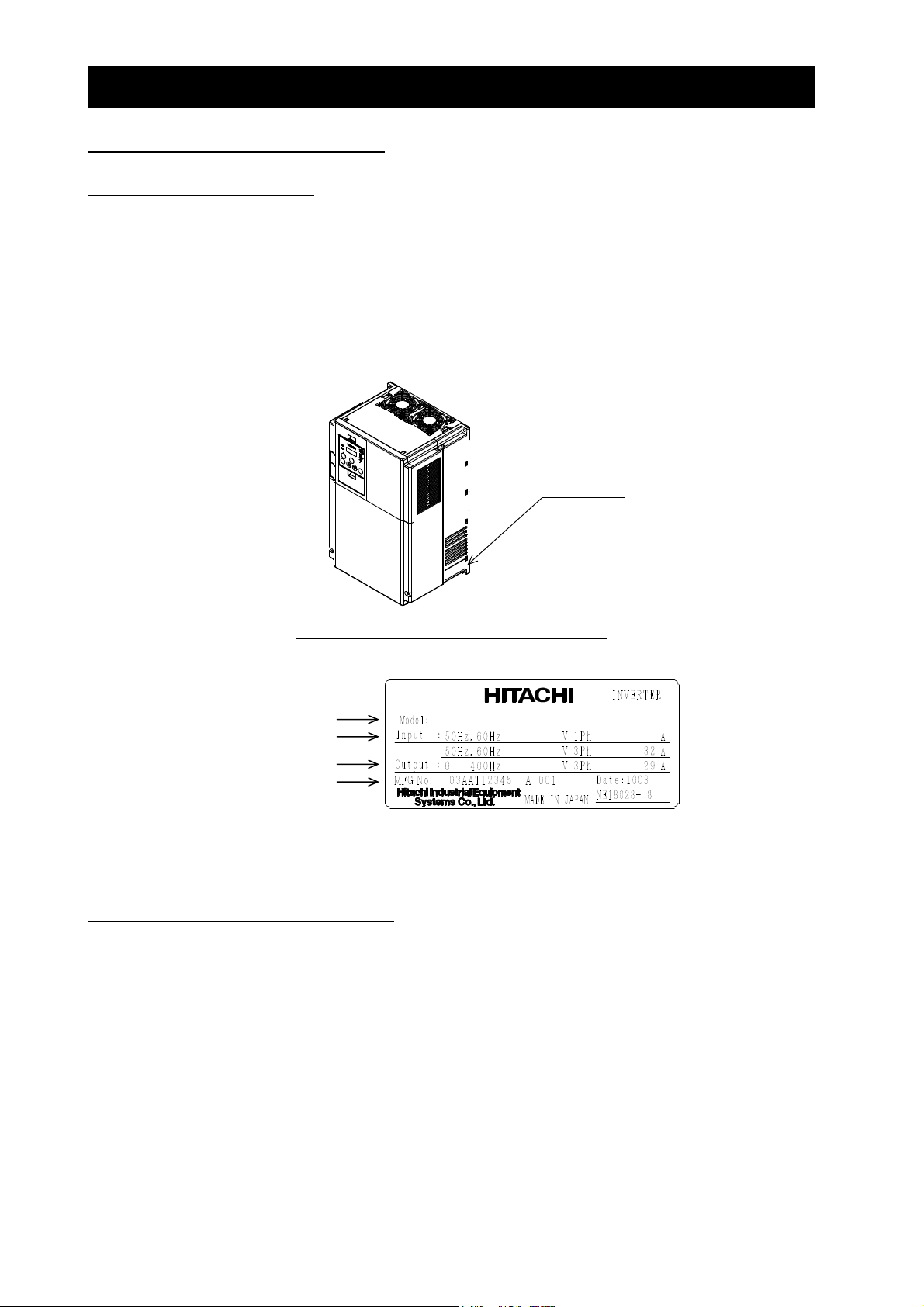
(1) Check the product for damage (including falling of parts and dents in the inverter body) caused during
transportation.
(2) Check that the product package contains an inverter set and this Instruction Manual.
(3) Check the specification label to confirm that the product is the one you ordered.
Specification
label
Figure 1-1 Location of the specifications label
Inverter model
Input ratings
Output ratings
Serial number
L700-150HFF
380 - 480
380 - 480
Figure 1-2 Contents of the specifications label
1.1.2 Instruction manual (this manual)
This Instruction Manual (Quick Reference Guide) describes how to operate the Hitachi L700 Series
Inverter.
Read this Instruction Manual thoroughly before using the inverter, and then keep it handy for future
reference.
When using the inverter, together with optional products for the inverter, also refer to the manuals supplied
with the optional products.
Note that this Instruction Manual and the manual for each optional product to be used should be delivered
to the end user of the inverter.
1 - 2

Chapter 1 Overview
1.2 Method of Inquiry and Product Warranty
1.2.1 Method of inquiry
For an inquiry about product damage or faults or a question about the product, notify your supplier of the
following information:
(1) Model of your inverter
(2) Serial number (MFG No.)
(3) Date of purchase
(4) Content of inquiry
- Location and condition of damage
- Content of your question
1.2.2 Product warranty
The product will be warranted for one year after the date of purchase.
Even within the warranty period, repair of a product fault will not be covered by the warranty (but the repair
will be at your own cost) if:
(1) the fault has resulted from incorrect usage not conforming to the instructions given in this Instruction
Manual or the repair or modification of the product carried out by an unqualified person,
(2) the fault has resulted from a cause not attributable to the delivered product,
(3) the fault has resulted from use beyond the limits of the product specifications, or
(4) the fault has resulted from disaster or other unavoidable events.
The warranty will only apply to the delivered inverter and excludes all damage to other equipment and
facilities induced by any fault of the inverter.
The warranty is effective only in Japan.
Repair at the user's charge
Following the one-year warranty period, any examination and repair of the product will be accepted at your
charge. Even during the warranty period, examination and repairs of faults, subject to the above scope of
the warranty disclaimer, will be available at charge.
To request a repair at your charge, contact your supplier or local Hitachi Distributor.
The Hitachi Distributors are listed on the back cover of this Instruction Manual.
1.2.3 Warranty Terms
The warranty period under normal installation and handling conditions shall be two (2) years from the date
of manufacture (“DATE” on product nameplate), or one (1) year from the date of installation, whichever
occurs first. The warranty shall cover the repair or replacement, at Hitachi’s sole discretion, of ONLY the
inverter that was installed.
(1) Service in the following cases, even within the warranty period, shall be charged to the purchaser:
a. Malfunction or damage caused by mis-operation or modification or improper repair
b. Malfunction or damage caused by a drop after purchase and transportation
c. Malfunction or damage caused by fire, earthquake, flood, lightening, abnormal input voltage,
contamination, or other natural disasters
(2) When service is required for the product at your work site, all expenses associated with field repair
shall be charged to the purchaser.
(3) Always keep this manual handy; please do not loose it. Please contact your Hitachi distributor to
purchase replacement or additional manuals.
1-3
Chapter 1 Overview
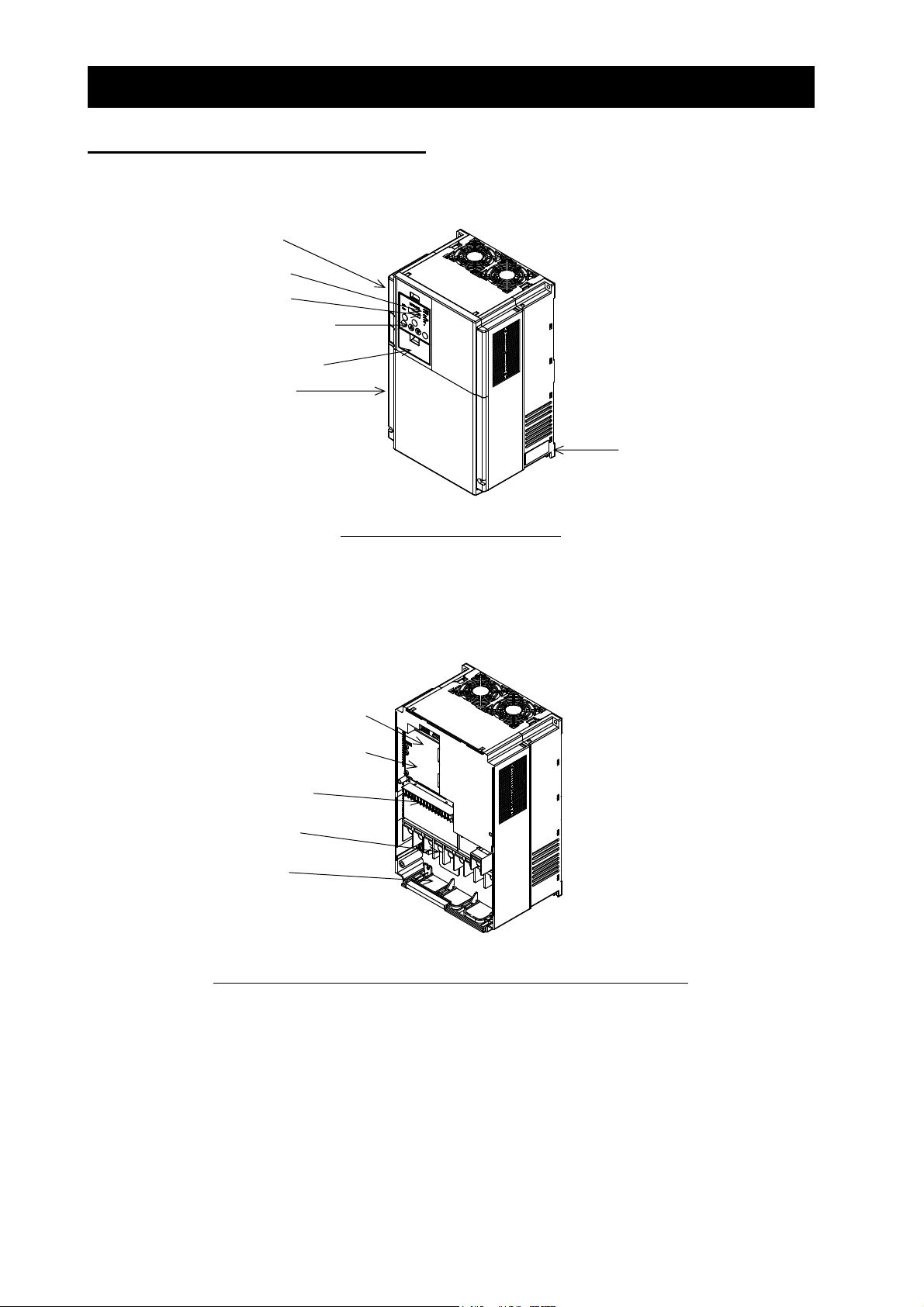
1.3 Exterior Views and Names of Parts
The figure below shows an exterior view of the inverter (model L700-185LFF/HFF to L700-300LFF/HFF).
Terminal block cover
For the wiring of the main circuit and control circuit terminals, open the terminal block cover.
For mounting optional circuit boards, open the front cover.
Position to mount optional board 1
Position to mount optional board 2
Control circuit terminals
Front cover
POWER lamp
ALARM lamp
Digital operator
Spacer cover
Specification label
Exterior view of shipped inverter
Main circuit terminals
Backing plate
Exterior view of inverter with front and terminal block covers removed
1 - 4

Chapter 2 Installation and Wiring
This chapter describes how to install the inverter and the wiring of main circuit
and control signal terminals with typical examples of wiring.
2.1 Installation ························································ 2 - 2
2.2 Wiring ······························································· 2 - 6

Chapter 2 Installation and Wiring
2.1 Installation
CAUTION
!
- Install the inverter on a non-flammable surface, e.g., metal. Otherwise, you run the risk of fire.
- Do not place flammable materials near the installed inverter. Otherwise, you run the risk of fire.
- When carrying the inverter, do not hold its top cover. Otherwise, you run the risk of injury by dropping
the inverter.
- Prevent foreign matter (e.g., cut pieces of wire, sputtering welding materials, iron chips, wire, and
dust) from entering the inverter. Otherwise, you run the risk of fire.
- Install the inverter on a structure able to bear the weight specified in this Instruction Manual.
Otherwise, you run the risk of injury due to the inverter falling.
- Install the inverter on a vertical wall that is free of vibrations. Otherwise, you run the risk of injury due
to the inverter falling.
- Do not install and operate the inverter if it is damaged or its parts are missing. Otherwise, you run the
risk of injury.
- Install the inverter in a well-ventilated indoor site not exposed to direct sunlight. Avoid places where
the inverter is exposed to high temperature, high humidity, condensation, dust, explosive gases,
corrosive gases, flammable gases, grinding fluid mist, or salt water. Otherwise, you run the risk of fire.
- The inverter is precision equipment. Do not allow it to fall or be subject to high impacts, step on it, or
place a heavy load on it. Doing so may cause the inverter to fail.
2 - 2
Chapter 2 Installation and Wiring
A
2.1.1 Precautions for installation
(1) Transportation
The inverter uses plastic parts. When carrying the inverter, handle it carefully to prevent damage to the
parts.
Do not carry the inverter by holding the front or terminal block cover. Doing so may cause the inverter
to fall. Do not install and operate the inverter if it is damaged or its parts are missing.
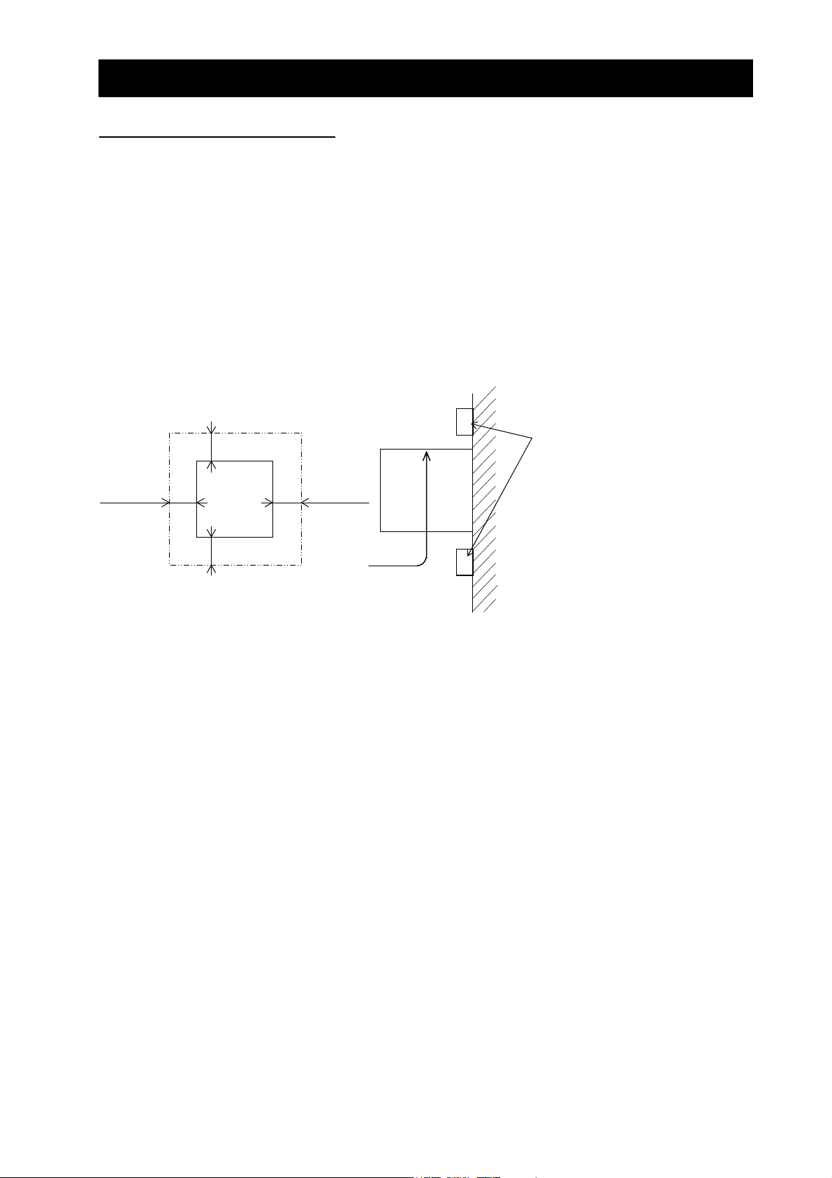
(2) Surface on which to install the inverter
The inverter will reach a high temperature (up to about 150°C) during operation. Install the inverter on
a vertical wall surface made of nonflammable material (e.g., metal) to avoid the risk of fire.
Leave sufficient space around the inverter. In particular, keep sufficient distance between the inverter
and other heat sources (e.g., braking resistors and reactors) if they are installed in the vicinity.
(*1)
ir flow
Inverter
Inverter
5 cm or more 5 cm or more
(*2)
(3) Ambient temperature
Avoid installing the inverter in a place where the ambient temperature goes above or below the
allowable range (-10°C to +40°C), as defined by the standard inverter specification.
Measure the temperature in a position about 5 cm distant from the bottom-center point of the inverter,
and check that the measured temperature is within the allowable range.
Operating the inverter at a temperature outside this range will shorten the inverter life (especially the
capacitor life).
(4) Humidity
Avoid installing the inverter in a place where the relative humidity goes above or below the allowable
range (20% to 90% RH), as defined by the standard inverter specification.
Avoid a place where the inverter is subject to condensation.
Condensation inside the inverter will result in short circuits and malfunctioning of electronic parts. Also
avoid places where the inverter is exposed to direct sunlight.
(5) Ambient air
Avoid installing the inverter in a place where the inverter is subject to dust, corrosive gases,
combustible gases, flammable gases, grinding fluid mist, or salt water.
Foreign particles or dust entering the inverter will cause it to fail. If you use the inverter in a
considerably dusty environment, install the inverter inside a totally enclosed panel.
Keep enough clearance between the inverter
and the wiring ducts located above and
below the inverter to prevent the latter from
obstructing the ventilation of the inverter.
*1 10 cm or more for 11 to 75kW
30cm or more for 90 to 160kW
*2 10 cm or more for 11 to 75kW
30cm or more for 90 to 160kW
But for exchanging the DC bus capacitor,
take a distance.
22cm or more for 18.5 to 75kW
Wall
30cm or more for 90 to 160kW
2 - 3
Chapter 2 Installation and Wiring
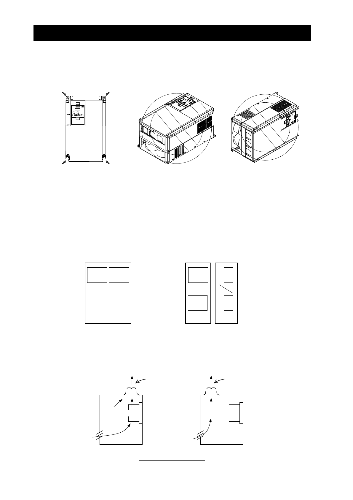
(6) Installation method and position
Install the inverter vertically and securely with screws or bolts on a surface that is free from vibrations
and that can bear the inverter weight.
If the inverter is not installed vertically, its cooling performance may be degraded and tripping or
inverter damage may result.
(7) Mounting in an enclosure
Heat in the inverter rises from the under to the upper part of the inverter up with the fan built into the
inverter, and make it to the one without the obstacle even if the influence of heat is received, please
when you arrange apparatus up.
Moreover, please usually arrange it sideways like the left side of the figure below when you store two or
more inverters in the same enclosure.
The temperature in an upper inverter rises because of the heat of a lower inverter when it places one
behind another unavoidably to reduce the space of the enclosure, it causes the inverter breakdown,
and set it up, please so that the heat of a lower inverter should not influence an upper inverter.
Please note it enough as ventilation, ventilation, and the size of the board are enlarged so that the
ambient temperature of the inverter should not exceed the permissible value when two or more
inverters are stored on the enclosure.
(8) When mounting multiple inverters in an enclosure with a ventilation fan, carefully design the layout of
the ventilation fan, air intake port, and inverters.
An inappropriate layout will reduce the inverter-cooling effect and raise the ambient temperature. Plan
the layout so that the inverter ambient temperature will remain within the allowable range.
Inverter Inverter
Enclosure
Sideways
Inverter
(Acceptable)
Inverter
Guide
Plate
Inverter
Enclosure
Behind another
Ventilation fan
Position of ventilation fan
2 - 4
Ventilation fan
Inverter
(Unacceptable)
Chapter 2 Installation and Wiring
(9) Reduction of enclosure size
If you mount the inverter inside an enclosure such that the heat sink of the inverter is positioned
outside the enclosure, the amount of heat produced inside the enclosure can be reduced and likewise
the size of the enclosure.
Mounting the inverter in an enclosure with the heat sink positioned outside requires an optional
dedicated special metal fitting.
To mount the inverter in an enclosure with the heat sink positioned outside, cut out the enclosure panel
according to the specified cutting dimensions.
The cooling section (including the heat sink) positioned outside the enclosure has a cooling fan.
Therefore, do not place the enclosure in any environment where it is exposed to waterdrops, oil mist,
or dust.
(10) Approximate loss by inverter capacity
Inverter capacity (kW) 11 15 18.5 22 30 37 45 55 75 90 110 132 160
Loss with 70% load (W) 435 575 698 820 1100 1345 1625 1975 2675 3375 3900 4670 5660
Loss with 100% load (W) 600 800 975 1150 1550 1900 2300 2800 3800 4800 5550 6650 8060
Efficiency at rated output (%) 94.8 94.9 95.0 95.0 95.0 95.1 95.1 95.1 95.2 95.2 95.2 95.2 95.2
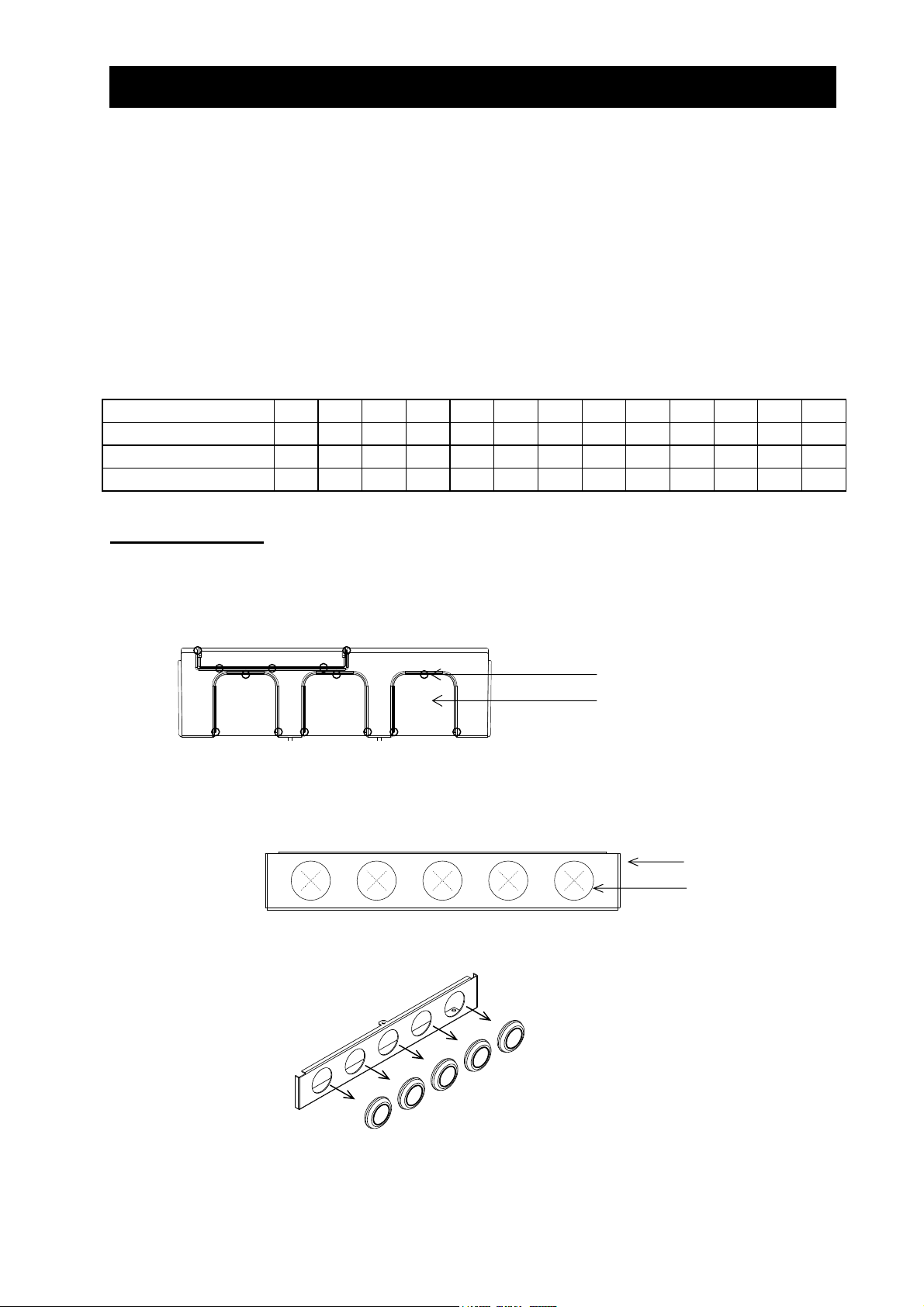
2.1.2 Backing plate
(1) For models with 30 kW or less capacity
On the backing plate, cut the joints around each section to be cut off with cutting pliers or a cutter,
remove them, and then perform the wiring.
Joint
Section to be cut off
(2) For the models with 37 kW to 75kW
1) For wiring without using conduits
Cut an X in each rubber bushing of the backing plate with cutting pliers or a cutter, and then perform
the wiring.
Backing plate
Rubber bushing
2) For wiring using conduits
Remove the rubber bushings from the holes to be used for wiring with conduits, and then fit conduits
into the holes.
Note: Do not remove the rubber bushing from holes that are not used for wiring with a conduit.
If a cable is connected through the plate hole without a rubber bushing and conduit, the cable
insulation may be damaged by the edge of the hole, resulting in a short circuit or ground fault.
2 - 5
Chapter 2 Installation and Wiring
2.2 Wiring
WARNING
!
- Be sure to ground the inverter. Otherwise, you run the risk of electric shock or fire.
- Commit wiring work to a qualified electrician. Otherwise, you run the risk of electric shock or fire.
- Before wiring, make sure that the power supply is off. Otherwise, you run the risk of electric shock or
fire.
- Perform wiring only after installing the inverter. Otherwise, you run the risk of electric shock or injury.
- Do not remove rubber bushings from the wiring section. Otherwise, the edges of the wiring cover may
damage the wire, resulting in a short circuit or ground fault.
CAUTION
!
- Make sure that the voltage of AC power supply matches the rated voltage of your inverter. Otherwise,
you run the risk of injury or fire.
- Do not input single-phase power into the inverter. Otherwise, you run the risk of fire.
- Do not connect AC power supply to any of the output terminals (U, V, and W). Otherwise, you run the
risk of injury or fire.
- Do not connect a resistor directly to any of the DC terminals (PD, P, and N). Otherwise, you run the
risk of fire.
- Connect an earth-leakage breaker to the power input circuit. Otherwise, you run the risk of fire.
- Use only the power cables, earth-leakage breaker, and magnetic contactors that have the specified
capacity (ratings). Otherwise, you run the risk of fire.
- Do not use the magnetic contactor installed on the primary and secondary sides of the inverter to stop
its operation.
- Tighten each screw to the specified torque. No screws must be left loose. Otherwise, you run the risk
of fire.
- Before operating, slide switch SW1 in the inverter, be sure to turn off the power supply. Otherwise, you
run the risk of electric shock and injury.
- Since the inverter supports two modes of cooling-fan operation, the inverter power is not always off,
even when the cooling fan is stopped. Therefore, be sure to confirm that the power supply is off before
wiring. Otherwise, you run the risk of electric shock and injury.
2 - 6
Chapter 2 Installation and Wiring
RSTR0T0UVWPPDRBNFW7618FM
O
LAM
SN
2
ALARM
VA
運転
停止/
リセット
11
RTTH
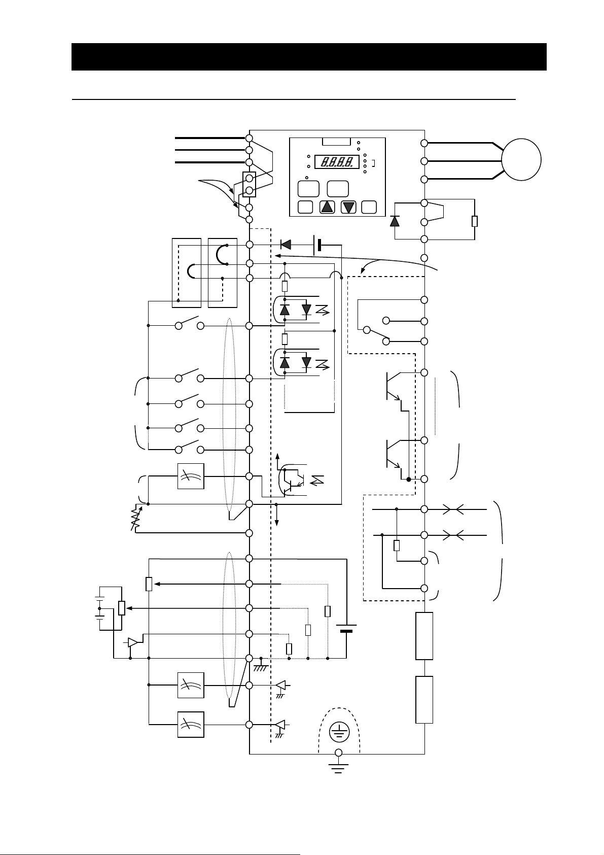
2.2.1 Terminal connection diagram and explanation of terminals and switch settings
3-phase power supply
200 V class: 200 to 240 V +10%, -15%
(50/60 Hz ±5%)
400 V class: 380 to 480 V +10%, -15%
(50/60 Hz ±5%)
When connecting separate
power supplies to main and
control circuits, remove J51
connector cables beforehand.
(See page 2-17)
Default jumper position
(sinking type inputs)
Forward rotation
command
Intelligent input
(8 contacts)
Jumper
Power supply for
control circuit
J51
P24
PLC
CM1
RUN
PRG
機能
FUNC
RUN
HITACHI
1
DC24V
STOP/RESET
POWER
記憶
STR
Hz
kW
%
Jumper
bar
The dotted line indicates the
detachable control terminal
AL0
board.
AL1
Intelligent relay output contact
(default: alarm output)
IM
Motor
Braking resistor
(optional)
(Models with 30kW
or less capacity
have a built-in BRD
circuit.)
AL2
15
Intelligent output
(5 terminals)
Digital monitor output
(PWM output)
Frequency
setting circuit
500 to 2,000Ω
Analog monitor
output (voltage
output)
Analog monitor
output (current
output)
Thermistor
0 to 10 VDC (12 bits)
-10 to +10 VDC (12 bits)
4 to 20 mA (12 bits)
0 to 10 V (10 bits)
4 to 20 mA (10 bits)
CM1
H
O2
OI
AMI
100Ω
10kΩ
CM2
SP
RP
For terminating
resistor
SN
10kΩ
DC10V
Option 1
Option 2
Type-D grounding (for 200 V class model)
Type-C grounding (for 400 V class model)
(See page 2-12.)
RS485
2 - 7
Chapter 2 Installation and Wiring
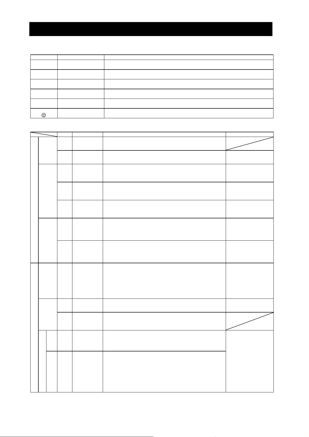
(1) Explanation of main circuit terminals
Symbol Terminal name Description
R, S, T
(L1, L2, L3)
U, V, W
(T1, T2, T3)
PD, P
(+1, +)
P, R B
(+, RB)
P, N
(+, -)
G
Main power input
Inverter output Connect a 3-phase motor.
DC reactor connection
External braking
resistor connection
Regenerative braking
unit connection
Inverter ground
(2) Explanation of control circuit terminals
Symbol Terminal name Description Electric property
Power
supply
Analog
Frequency setting input
Monitor output
AMI
Monitor output
P24
CM1
Power supply
Digital (contact)
Operation
command
Contact input
switching
Function selection and logic
L
H
O
O2
OI
AM
FM
FW
1
2
3
4
5
6
7
8
Analog power
supply
(common)
Frequency
setting power
supply
Frequency
command
(voltage)
Auxiliary
frequency
command
(voltage)
Frequency
command
(current)
Analog monitor
(voltage)
Analog monitor
(current)
Digital monitor
(voltage)
Interface power
supply
Interface power
supply
(common)
Forward rotation
command
Intelligent input
Connect to the AC power supply.
Leave these terminals unconnected when using a regenerative converter (HS900 series).
Remove the jumper from terminals PD and P, and connect the optional power factor reactor
(DCL).
Connect the optional external braking resistor.
(The RB terminal is provided on models with 30 kW or less capacity.)
Connect the optional regenerative braking unit (BRD).
Connect to ground for grounding the inverter chassis by type-D grounding (for 200 V class
models) or type-C grounding (for 400 V class models).
This common terminal supplies power to frequency command terminals (O,
O2, and OI) and analog output terminals (AM and AMI). Do not ground this
terminal.
This terminal supplies 10 VDC power to the O, O2, OI terminals.
Input a voltage (0 to 10 VDC) as a frequency command. 10 V specifies the
maximum frequency.
To specify the maximum frequency with a voltage of 10 V or less, set the
voltage using function "A014".
Input a voltage (0 to ±10 VDC) as a signal to be added to the frequency
command input from the O or OI terminal. You can input an independent
frequency command from this terminal (O2 terminal) alone by changing the
setting.
Input a current (4 to 20 mA DC) as a frequency command. 20 mA specifies
the maximum frequency.
The OI signal is valid only when the AT signal is on. Assign the AT function
to an intelligent input terminal.
This terminal outputs one of the selected "0 to 10 VDC voltage output"
monitoring items. The monitoring items available for selection include
output frequency, output current, output torque (signed or unsigned),
output voltage, input power, electronic thermal overload, LAD frequency,
motor temperature, heat sink temperature, and general output.
This terminal outputs one of the selected "4 to 20 mA DC current output"
monitoring items. The monitoring items available for selection include
output frequency, output current, output torque (unsigned), output voltage,
input power, electronic thermal overload, LAD frequency, motor
temperature, heat sink temperature, and general output.
This terminal outputs one of the selected "0 to 10 VDC voltage output
(PWM output mode)" monitoring items. The monitoring items available for
selection include output frequency, output current, output torque
(unsigned), output voltage, input power, electronic thermal overload, LAD
frequency, motor temperature, heat sink temperature, general output,
digital output frequency, and digital current monitor.
For the items "digital output frequency" and "digital current monitor," this
terminal outputs a digital pulse signal at 0/10 VDC with a duty ratio of 50%.
This terminal supplies 24 VDC power for contact input signals.
If the source logic is selected, this terminal is used as a common contact
input terminal.
This common terminal supplies power to the interface power supply (P24),
thermistor input (TH), and digital monitor (FM) terminals. If the sink logic is
selected, this terminal is used as a common contact input terminal. Do not
ground this terminal.
Turn on this FW signal to start the forward rotation of the motor; turn it off to
stop forward rotation after deceleration.
Select eight of a total 60 functions, and assign these eight functions to
terminals 1 to 8.
Note:
If the emergency stop function is used, terminals 1 and 3 are used
exclusively for the function. For details, see Item (3), "Emergency stop
function" (on page 2-8).
Allowable load current:
20 mA or less
Input impedance: 10kΩ
Allowable input voltages:
-0.3 to +12 VDC
Input impedance: 10kΩ
Allowable input voltages:
0 to ±12 VDC
Input impedance: 10kΩ
Maximum allowable
current: 24 mA
Maximum allowable
current: 2 mA
Allowable load impedance:
250Ω or less
Maximum allowable
current: 1.2 mA
Maximum frequency:
3.6 kHz
Maximum allowable output
current: 100 mA
[Conditions for turning
contact input on]
Voltage across input and
PLC: 18 VDC or more
Input impedance between
input and PLC: 4.7kΩ
Maximum allowable voltage
across input and PLC:
27 VDC
Load current with 27 VDC
power: about 5.6 mA
2 - 8
Chapter 2 Installation and Wiring
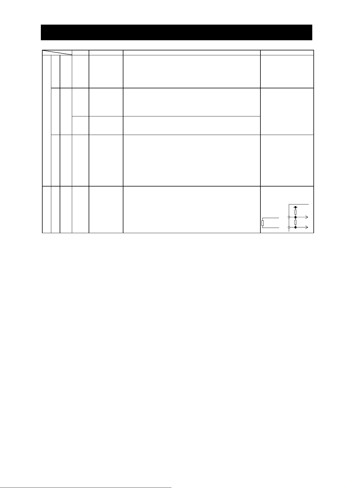
Symbol Terminal name Description Electric property
Intelligent input
PLC
Contact input
Function selection
and logic switching
11
12
13
14
15
Status and factor
Open collector output
Digital (contact)
Relay contact output
Analog
Analog input
CM2
AL0
AL1
AL2
Status and alarm
TH
Sensor
(common)
Intelligent output
Intelligent output
(common)
Intelligent relay
output
External
thermistor input
To switch the control logic between sink logic and source logic, change the
jumper connection of this (PLC) terminal to another terminal on the control
circuit terminal block.
Jumper terminals P24 and PLC for the sink logic; jumper terminals CM1
and PLC for the sink logic.
To use an external power supply to drive the contact inputs, remove the
jumper, and connect the PLC terminal to the external interface circuit.
Select five of a total 51 functions, and assign these five functions to
terminals 11 to 15.
If you have selected an alarm code using the function "C062", terminals 11
to 13 or 11 to 14 are used exclusively for the output of cause code for alarm
(e.g., inverter trip). The control logic between each of these terminals and
the CM2 terminal always follows the sink or source logic.
This terminal serves as the common terminal for intelligent output terminals
[11] to [15].
Select functions from the 43 available, and assign the selected functions to
these terminals, which serve as C contact output terminals.
In the initial setting, these terminals output an alarm indicating that the
inverter protection function has operated to stop inverter output.
Connect to an external thermistor to make the inverter trip if an abnormal
temperature is detected.
The CM1 terminal serves as the common terminal for this terminal.
[Recommended thermistor properties]
Allowable rated power: 100 mW or more
Impedance at temperature error: 3kΩ
The impedance to detect temperature errors can be adjusted within the
range 0Ω to 9,999Ω.
Voltage drop between each
terminal and CM2 when
output signal is on: 4 V or
less
Maximum allowable
voltage: 27 VDC
Maximum allowable
current: 50 mA
(Maximum contact
capacity)
AL1-AL0: 250 VAC, 2 A
(resistance) or 0.2 A
(inductive load)
AL2-AL0: 250 VAC, 1 A
(resistance) or 0.2 A
(inductive load)
(Minimum contact capacity)
100 VAC, 10 mA
5 VDC, 100 mA
Allowable range of input
voltages
0 to 8 VDC
[Input circuit]
TH
Thermistor
CM1
DC8V
10kΩ
1kΩ
2 - 9
Chapter 2 Installation and Wiring
ON
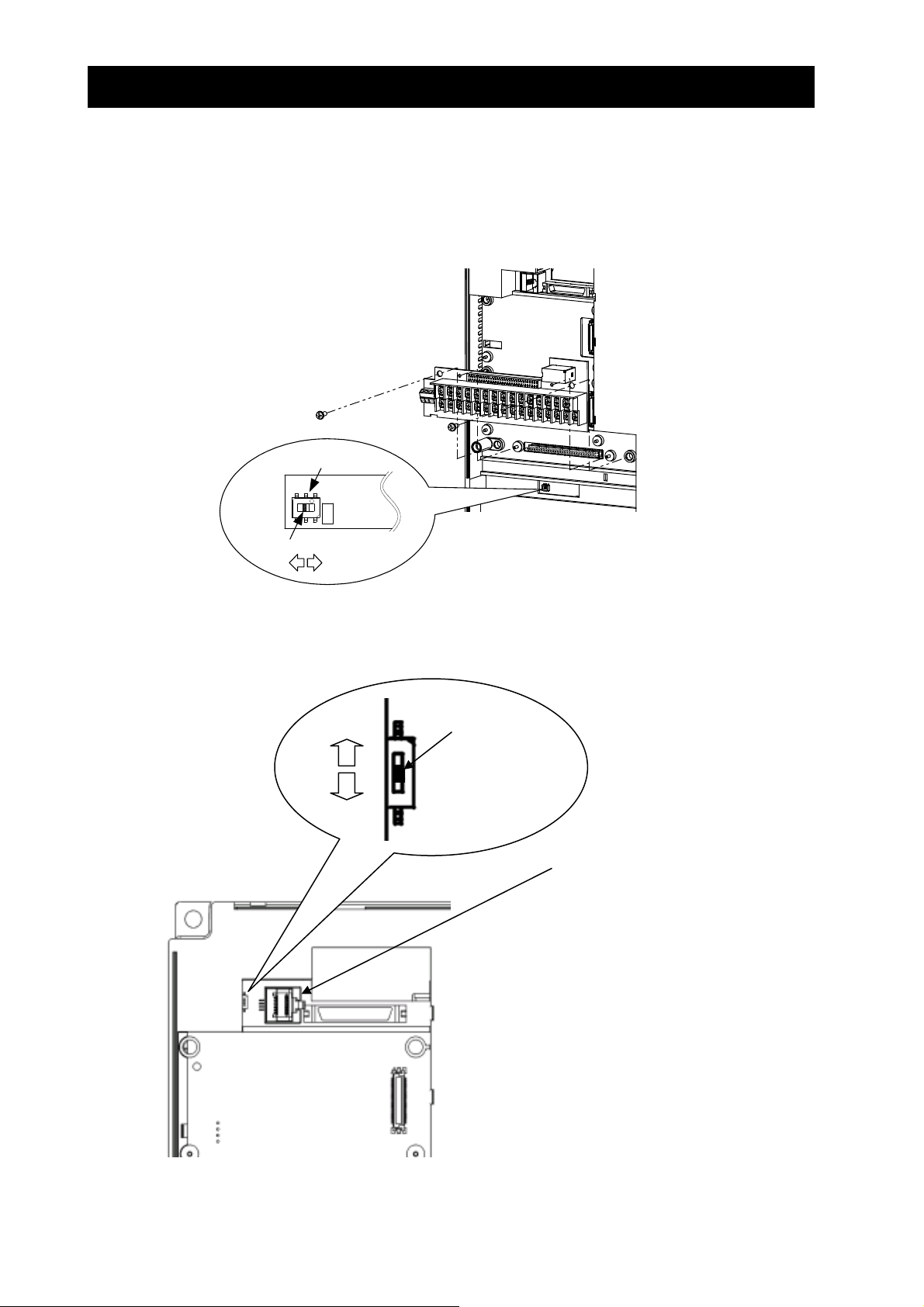
(3) Explanation of switch
SW1: It is a switch that switches effective and the invalidity of the urgent disconnect function (The
state of the factory shipment: this function invalidity).
Please use the urgent invalidity function after perusing "4.4 urgent disconnect function".
Note: Slide Switch 12
Some models have slide switch in the position as shown below. Default setting of this switch is at "ON" position.
Please don't change the setting. If it is changed, inverter may trip and disabled to run.
Slide switch SW1
ON
Slide lever (factory setting: OFF)
OFF
OFF
ON
ON
Slide switch SW12
Slide lever
(factory setting: ON)
Logic board
2 - 10
 Loading...