

Hitachi IC35L018UWDY10, IC35L073UWDY10, IC35L018UCDY10, IC35L073UCDY10, IC35L036UWDY10 Quick Installation Guide
...Page 1
Quick installation guide
Page 1
version
1
.0
Hitachi Ultrastar 146Z10
Ultra 160 and 320 SCSI
Models:
IC35L018UWDY10 IC35L073UWDY10
IC35L018UCDY10 IC35L073UCDY10
IC35L036UWDY10 IC35L146UWDY10
IC35L036UCDY10 IC35L146UCDY10
Handling precautions
Ÿ Do not open the electrostatic discharge (ESD) bag
containing the drive until required.
Ÿ Do not apply pressure on the drive during handling
or installation.
Ÿ To prevent damage from impact or vibration always
set the drive down gently.
Ÿ Handle the drive carefully by the edges. Do not
touch the exposed printed circuit board or any
electronic components.
Ÿ Do not cover the breather hole! Covering the
breather hole may result in loss of data.
Ÿ Save the packaging materials including the ESD
bag in the event that the drive must be returned.
Installing the drive
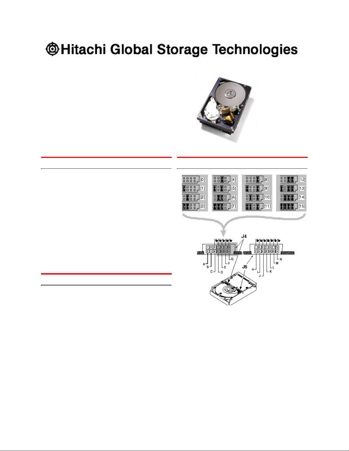
Address jumper and drive option blocks
1. Backup all data.
2. Record the serial number and part number of your
hard drive for future reference.
3. Turn off the computer and remove the computer
system cover.
4. Before handling the hard disk drive, discharge any
static electricity from yourself and your clothing.
With one hand touch an unpainted metal surface
on the computer chassis, then touch the ESD bag
with the other hand for a minimum of two seconds.
5. Remove the hard drive from the ESD bag.
6. Unplug the computer.
7. Assign a SCSI address (0 through 15) to the drive
by installing a jumper on the appropriate ID bits
(pin pairs D, E, F, and G) on jumper block J4 as
shown on the shaded area in the illustration below.
Address 6 is the shipping default for 68-pin models
Address 7 is normally reserved for the host adapter
8. Select the desired options by placing a jumper on
the pin pair for that option. The options are listed
below cross-referenced by a letter to the two jumper blocks in the above illustration. Refer to the
Ultrastar 146Z10 product summary for a description of the options.
Pin pair for LED connectionA
Termination Power (68-pin model only)B
Force Single-ended ModeC
Enable Auto Spin (68-pin model)
H
Disable Auto Spin (80-pin model
Auto Start DelayI
Delay Start 6/12J
Disable ParityK
Target Initiated Sync NegotiationL
Disable Unit AttentionM
ReservedN
Page 2

SPECIAL NOTES:
Page 2
version
1
.0
Ÿ For this drive to operate in LVD mode all SCSI de-
vices including the SCSI bus host adapter must be
LVD devices.
Ÿ The drive is designed to detect if the SCSI bus is
LVD or SE. The drive will function based upon the
mode that it detects. If for some reason the drive
cannot detect an SE mode bus, place a jumper on
pins 5 & 6 of jumper block J-4 to force SE mode.
Ÿ On 68 pin drives termination power must be
provided. In most cases it is provided by the host
adapter. If it is not, install a jumper on pins 3 & 4 of
jumper block J-4 to enable termination power. See
the illustration above. (The 80-pin drive does not
provide termination power.)
9. For a 68-pin drive attach the power cable and
ensure that one end of the SCSI cable is connected to the host adapter. Attach a terminator to
the end of the SCSI cable furthest from the host
adapter. If the drive is the only device on the SCSI
cable, attach it to the cable connector closest to the
terminator. Additional drives may be attached to
any unused connector. [The 80-pin drive is
plugged into server backplanes and requires no
cables.]
10.Using the appropriate brackets or rails, mount the
drive with any of its six surfaces facing down.
11.Retrieve any loose screws or parts from within the
computer.
12.Ensure that cables are properly routed.
13.Plug in your computer. Do not turn it on.
14.Insert the operating system (OS) setup diskette into
the floppy drive.
15.Turn on your computer.
Ÿ If the system boots up, turn off your computer
and replace the cover.
Ÿ If your system does not boot up, turn off your
computer and check all connections and set tings. Turn on and boot the system.
Ÿ If the system still fails to boot up, turn off your
computer and remove the new drive to return
the system to its original configuration. Contact
the IBM Technology Group Support Center for
assistance.
Partitioning and formatting (using DOS 5.0 or later)
CAUTION: Partitioning and formatting will destroy any
previous data. When partitioning and formatting a drive
in a system with more than one drive be sure that you
select the correct hard drive.
1. With the OS setup diskette inserted in the floppy
drive, turn on the computer.
2. At the DOS prompt type FDISK, press ENTER, and
follow the instructions on the screen.
3. To format the primary system drive, type
FORMAT C:/S at the DOS command prompt and
press ENTER. The /S parameter makes C: the
operating system startup drive.
4. To format a second drive (not C:), type FORMAT X:
(where X is the drive letter assigned by FDISK) at
the DOS prompt and press ENTER.
5. Remove the diskette and restart your computer.
The partitioning and format ting is complete.
6. Install the operating system.
© Copyright Hitachi Global Storage Technologies 2003
Hitachi Global Storage Technologies
5600 Cottle Road
San Jose, CA 95193
Produced in the United States
1/03
All rights reserved
DeskstarTM is a trademark of Hitachi Global Storage
Technologies. Microsoft, Windows XP, and Windows
are trademarks of Microsoft Corporation in the United
States, other countries, or both.
Other product names are trademarks or registered
trademarks of their respective companies.
References in this publication to Hitachi Global Storage
Technologies products, programs or services do not
imply that Hitachi Global Storage Technologies intends
to make these available in all countries in which Hitachi
Global Storage Technologies operates.
Product information is provided for information purposes
only and does not constitute a warranty. Information is
true as of the date of publication and is subject to
change. Actual results may vary.
This publication is for general guidance only.
Photographs may show design models.
13 January 2003
 Loading...