

Page 1
AV SURROUND RECEIVER
HTA-DD3E/EBS/W/WUN/WAU
Instruction Manual
Before operating please read all these instructions thoroughly.
Bitle lesen Sie diese Bedienungsanleitung vor der Inbetriebnahme sorglälting durch.
Veuiltez lire ces instructions dans le detail avant de meltre l’appareil en fonction.
Antes de ponerio en funcionamiento lea la totalidad de estas instrucciones.
Prima dell’uso, leggere attentamente le seguenti istruzioni.
Lees deze gebruiksaanwijzing aandachtig door alvorens dit toestel in gebruik te nemen.
Läs dessa anvïsningar noga, innan du borjar att använda apparaten.
Læs venligst instruktioneme igennem, før De tager apparatet i brug.
“DTS” and “DTS Digital Surround” are trademarks of Digital Theater Systems. Inc.
Manufactured under license from Dolby Laboratories.
“Dolby” , “Pro Logic” and the double D symbol are trademarks of Dolby Laboratories.
Confidential Unpublished Works. © 1992-1997 Dolby Laboratories, Inc. All rights reserved.
Page 2
ENGLISH
L DECLARATION OF CONFORMITY
We declare under our sole responsibility that this product, to which this declaration relates,
is in conformity with the following standards:
EN60065, EN55013, EN55020, EN61000-3-2 and EN61000-3-3.
Following the provisions of 73/23/EEC, 89/336/EEC and 93/68/EEC Directive.
L SAFETY PRECA UTIONS
• The POWER button on the front panel and remote control switches the unit from ON to
STANDBY but does not isolate the unit from the mains supply. If it is to be left unattended for
a long period of time, it is recommended that the unit is switched to standby and the mains
plug is removed from the socket.
• Check that all connections are proper and that there are no problems with the connection
cords. Always set the power to standby mode before connecting and disconnecting
connection cords.
• If no sound is emitted from the speakers when the POWER is ON, turn down the MASTER
VOLUME control and press the POWER button to switch the unit to standby mode. Then,
check if the speaker cords are properly connected.
• To prevent short circuits or damaged wires in the connection cords, always unplug the power
cord and disconnect the connection cords between all other audio components when moving
the unit.
• This unit contains a muting circuit and it takes about 5 – 6 seconds for this unit to reach
stable operation after switching the set to POWER ON mode.
• Never open the covers or touch the insides or insert a metal object. Any of these could cause
an electric shock or a fault.
• When an electrical storm is present, unplug the power cord and disconnect the antenna
connections.
• The apparatus should not be exposed to dripping or splashing.
• To clean the cabinets and panels when dirty, clean off dirt on the surfaces with a soft, dry
cloth. Never use thinner, benzene or alcohol, as these will damage the surface finish.
• Protect the unit against excessive heat (e.g. direct sunlight), dust and moisture.
• Be careful not to damage the power supply cord. Be sure to hold the plug when pulling it out;
do not pull the cord.
• Do not install the set in a confined location; otherwise, heat dissipation will be poor and
malfunctions may occur.
SAFEGUARDS
Electrical energy can perform many useful functions. This unit has been engineered and
manufactured to assure your personal safety. Improper use can result in potential
electrical shock or fire hazards. In order not to defeat the safeguards, observe the
following instructions for its installation, use and servicing.
L NOTES
• SWITCHING THE INPUT FUNCTION WHEN INPUT JACKS ARE NOT CONNECTED
A clicking noise may be produced if the input function is switched when nothing is connected to
the input jacks. If this happens, either turn down the MASTER VOLUME control or connect
components to the input jacks.
• MUTING OF PRE OUT JACKS
The PRE OUT jacks include a muting circuit. Because of this, the output signals are greatly
reduced for several seconds after the power operation switch is turned on or input function,
surround mode or any other set-up is changed.
If the volume is turned up during this time, the output will be very high after the muting circuit
stops functioning. Always wait until the muting circuit turns off before adjusting the volume.
2
TABLE OF CONTENTS
• Accessories............................................... 2
• Cautions on Installation............................. 2
• Connections ..........................................3~6
• Part Names and Functions .......................6
• Remote Control Unit .................................7
• Setting up the System ......................... 7~11
• Operations ........................................ 11~13
• ACCESSORIES
Check that the following parts are included in addition to the main unit HTA-DD3E:
• Instruction manual...............................................................................................................1
• Remote control unit (RB-DD1) ........................................................................................... 1
• R6P/AA Batteries ................................................................................................................2
• AM loop antenna .................................................................................................................1
• FM indoor antenna..............................................................................................................1
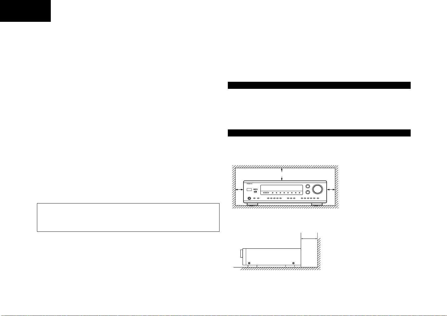
• CAUTIONS ON INSTALLATION
• Always install this unit horizontally.
• For proper heat dissipation, leave at least 10 cm of space between the top, back and sides
of this unit and the wall or other components.
*
10 cm or more
*
DOLBY
DIGITAL
*
10 cm or more
• Using the Surround Function ............ 13~18
• Listening to the Radio ....................... 19~22
• Last Function Memory ............................22
• Initialization of the Microprocessor.......... 22
• Troubleshooting ......................................23
• Specifications .......................................... 24
+-
+-
*
*
Wall
Page 3

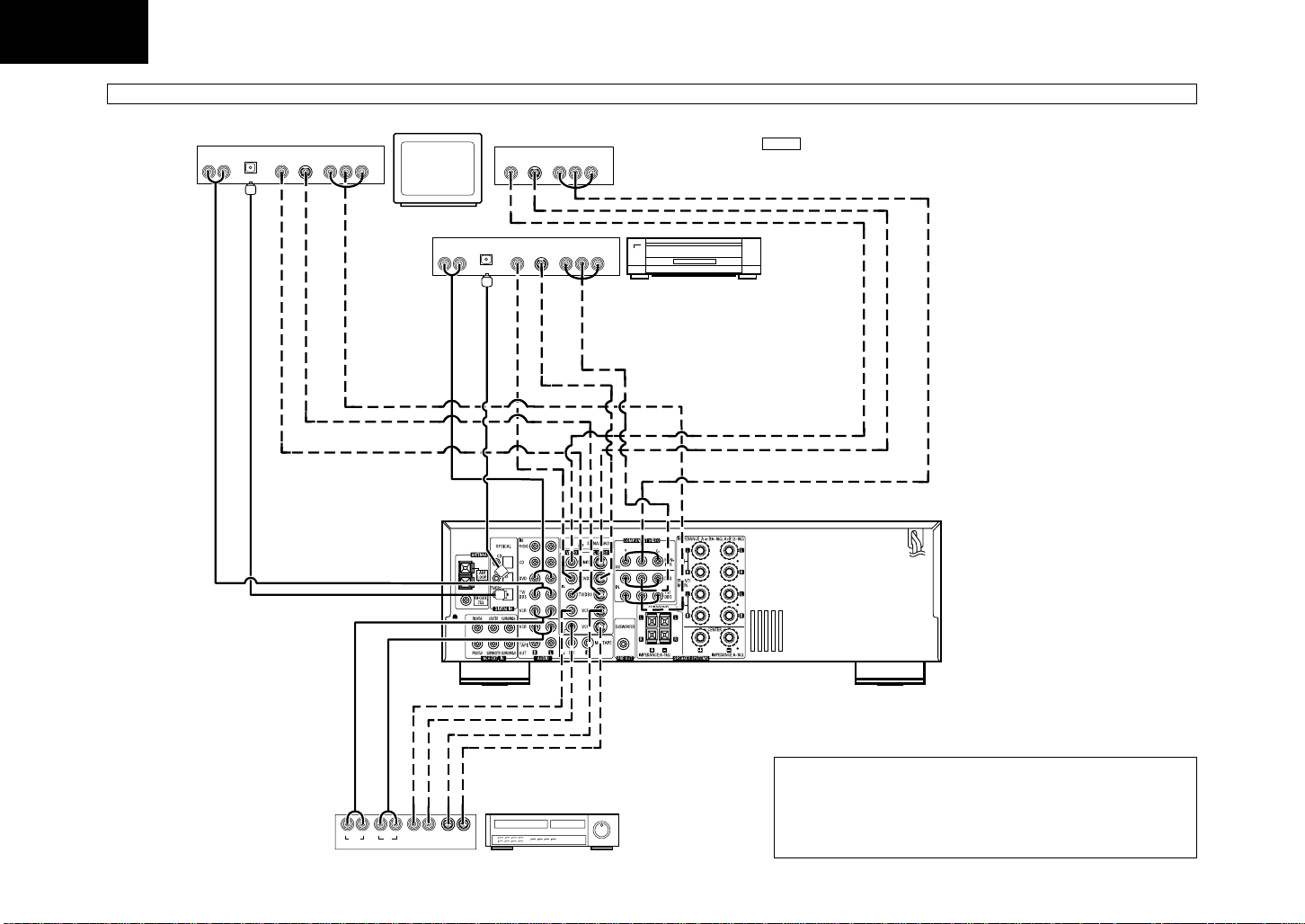
• CONNECTIONS
ENGLISH
Connecting the audio components
• Do not plug in the power cord until all connections have been completed.
• Be sure to connect the left and right channels properly (left with left, right with right).
• Inser t the plugs securely. Incomplete connections will result in the generation of noise.
• Note that binding pin plug cords together with power cords or placing them near a power transformer will
result in generating hum or other noise.
• Noise or humming may be generated if a connected audio equipment is used independently without turning
the power of this unit on. If this happens, turn on the power of the unit.
Decoders with 6-channel
analog outputs, etc.
LINE OUT
FRONT
SURROUND
CENTER
SUB WOOFER
Turntable (MM cartridge)
Ground wire
Connect the internal amplifier’s
subwoofer to the subwoofer terminal.
(Refer to page 5. )
PRE OUT jack
PRE OUT jacks
AC 230 V, 50 Hz
AC CORD
Connecting the antenna terminals
DIRECTION OF
BROADCASTING
STATION
FM ANTENNA
75 Ω/ohms
COAXIAL
CABLE
FM INDOOR ANTENNA
(An Accessory)
AM LOOP
ANTENNA
(An Accessory)
LINE IN
RL
INPUT
LINE OUT
Tape deck or MD
RL
OUTPUT
DIGITAL OUT
LINE OUT
OPITCAL
RL
OUTPUT
CD player
3
Page 4
ENGLISH
Connecting the video equipments
TV or DBS tuner output
AUDIO
AUDIO DIGITAL
VIDEO
OUT
L
R
OPTICAL
S VIDEO
OUT
OUT
OUT
COMPONENT VIDEO
OUT
YCBCR
Monitor TV input
VIDEOINS VIDEO
COMPONENT VIDEO
IN
IN
YCBCR
MONITOR OUT
• Connect the TV’s video input jack
(VIDEO INPUT) to the VIDEO
MONITOR OUT jack using a 75
Ω/ohms video coaxial pin plug
cord.
AUDIO OUT
AUDIO DIGITAL OUT
VIDEO OUT
S VIDEO OUT
COMPONENT VIDEO OUT
AUDIO
AUDIO DIGITAL
OUT
L
R
OPTICAL
AUDIO OUT
OUT
AUDIO DIGITAL OUT
VIDEO
S VIDEO
OUT
OUT
VIDEO OUT
S VIDEO OUT
COMPONENT VIDEO
OUT
YCBCR
COMPONENT
VIDEO OUT
DVD player
VIDEO IN
S VIDEO IN
COMPONENT VIDEO IN
NOTE
Please connect to either the VIDEO IN/OUT , S VIDEO IN/OUT or COMPONENT VIDEO
AUDIO OUT
R L OUT IN
RL
OUT
AUDIOAUDIO
VIDEO OUT
AUDIO IN
IN
VIDEO IN
VIDEO
S VIDEO OUT
S VIDEO IN
Video deck
OUT IN
S VIDEO
IN/OUT terminal, depending on your video component.
The signal from the VIDEO IN, S VIDEO IN and COMPONENT VIDEO IN terminals
comes from the VIDEO OUT , S VIDEO OUT and COMPONENT VIDEO OUT terminals
respectively. For example, the signal from the VIDEO IN terminal does not come from
the S VIDEO OUT or COMPONENT VIDEO OUT terminals.
4
Page 5
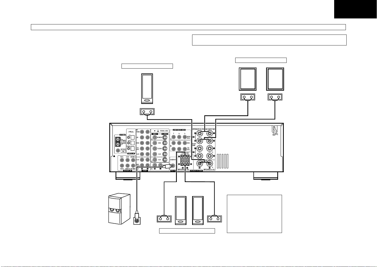
Speaker system connections
Speaker impedance
• When speaker systems A and B are used separately, speakers with an impedance of 6 to 16 Ω/ohms can be
connected for use as front speakers.
• Be careful when using two pairs of front speakers (A + B) at the same time, since use of speakers with an
impedance of 12 to 16 Ω/ohms.
• Speakers with an impedance of 6 to 16 Ω/ohms can be connected for use as center and surround speakers.
CENTER SPEAKER SYSTEM
_
+
NOTE:
NEVER touch the speaker terminals when the power is on. Doing so could result in electric shocks.
FRONT SPEAKER SYSTEMS
System A
(L) (R)
_
+
_
+
ENGLISH
Connection jack for subwoofer with
built-in amplifier (super woofer), etc.
(L) (R)
_
+
SURROUND SPEAKER SYSTEMS
• Precautions when connecting
speakers
If a speaker is placed near a TV
or video monitor, the colors on the
screen may be disturbed by the
speaker’s magnetism. If this
should happen, move the
_
+
speaker away to a position where
it does not have this effect.
5
Page 6
ENGLISH
AV SURROUND RECEIVER
HTA-DD3
REMOTE
SENSOR
DOWN CH
OFFON
AB
UP GROUP CDDVD TUNER VCRTV/DBS MD/TAPE MON PHONO
ON/STANDBY
ON / STANDBY
PHONES
SPEAKER
TUNER
UPDOWN MEMORY MODE
DOLBY/DTS
SURROUND
6CH
EXT.IN
MULTI
STEREO
DSP
SIMULATION
STEREO
BASS
TREBLE MASTER VOLUME
VOLUME LEVEL
+-
INPUT MODE
BAND
TUNING
SURROUND MODE
+-
DIGITAL DTS
LOCK
OFF
17 18 19 20 2122232425 26 27 28
16151413121110987654321
DOLBY
DIGITAL
RDSPTY RT
Radio
NOTE
• Protector circuit
This unit is equipped with a high–speed protection circuit. The purpose of this circuit is to protect the
speakers under circumstances such as when the output of the power amplifier is inadvertently shortcircuited and a large current flows, when the temperature surrounding the unit becomes unusually
high, or when the unit is used at high output over a long period which results in an extreme temperature
rise.
When the protection circuit is activated, the speaker output is cut off and the power supply indicator
LED flashes. Should this occur, please follow these steps: be sure to switch off the power of this unit,
check whether there are any faults with the wiring of the speaker cables or input cables, and wait for
the unit to cool down if it is very hot. Improve the ventilation condition around the unit and switch the
power back on.
If the protection circuit is activated again even though there are no problems with the wiring or the
ventilation around the unit, switch off the power and contact a HITACHI service center.
• Note on speaker impedance
The protector circuit may be activated if the set is played f or long periods of time at high v olumes when
speakers with an impedance lower than the specified impedance (for example speakers with an
impedance of lower than 4 Ω/ohms) are connected. If the protector circuit is activated, the speaker
output is cut off. Turn off the set’s power, wait for the set to cool down, improve the ventilation around
the set, then turn the power back on.
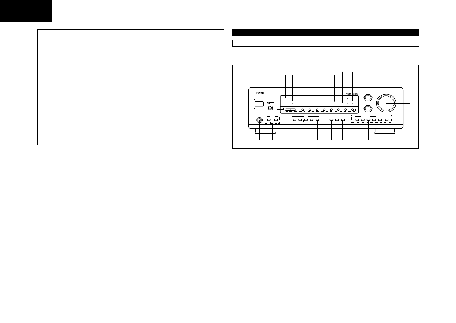
• PART NAMES AND FUNCTIONS
Front Panel
1. Power operation switch
2. Headphones jack (PHONES)
3. Front SPEAKER A/B buttons
4. TUNING UP/DOWN buttons
5. MEMORY button
6. MODE button
7. BAND button
8. PTY button
9. RT button
10. RDS button
11. DOLBY/DTS SURROUND button
12. DSP SIMULATION button
13. MULTI STEREO button
14. 6CH external input button (6 CH EXT. IN)
15. STEREO button
16. INPUT MODE selector button
17. Preset memory selector buttons
18. Remote control sensor (REMOTE SENSOR)
19. Power indicator (ON/STANDBY)
20. Display
21. Master volume indicator (VOLUME LEVEL)
22. DOLBY digital input indicator
23. Digital lock indicator (LOCK)
24. DTS input indicator
25. Input source selector buttons
26. TREBLE adjustment control
27. BASS adjustment control
28. MASTER VOLUME control
6
Page 7
ENGLISH
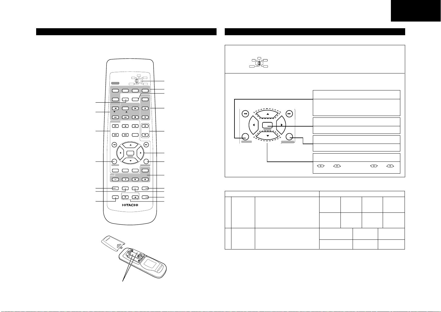
• REMOTE CONTROL UNIT
•
The remote control unit will operate from a direct distance of approximately 7 meters, but this distance
will be shortened if obstacles are present or if operated at an angle.
an angle of up to 30° in either direction.)
CHANNEL
FUNCTION
A/B
SURR.MODE
TAPE
ENTER
NEXT
CH VCL
MD DVD
VCR
MD/
TAPE MON
DISPLAY
MUTING
FUNCTION selector button
System buttons (TAPE, VCR)
System buttons
(CD, MD, DVD)
SYSTEM (SYSTEM SET UP) button
Surround mode selector button
Test tone button
POWER
HTA
MD/TAPE
TAPE / VCR
CD/MD/DVD
SET UP
SYSTEM
AUDIO TITLE MENU
TV
T.TONE
CH SELECT
Channel select button
REMOTE CONTROLLER
RB - DD1
(The remote control unit will operate at
CD
VOLUMECHANNEL
VIDEO SELECT
VCR
DVDTV
PRESET
GROUP
CHANNEL
MASTER
VOL
SURROUND
TV INPUT
STATUS
Mode selector switch
POWER buttons
MD/TAPE MONITOR button
Preset memory select buttons
MASTER VOLUME control
buttons
Cursor buttons
NEXT button
SURROUND
(surround parameter) button
System buttons (TV)
VIDEO SELECT button
MUTING button
STATUS button
CHANNEL VOLUME UP/
DOWN buttons
BATTERY INSERTION
• SETTING UP THE SYSTEM
• These settings are required to set up the listening room’s AV system centered around the unit.
1 Set the slide switch to “CD” or “MD”.
CD
MD DVD
VCRTAPE
2 Use the following buttons to set up the system:
SYSTEM (SYSTEM SET UP) button
Press this to display the system setup menu.
Also use this button to finish the setting on
the display .
ENTER
SET UP
SYSTEM
NEXT
SURROUND
• System setup items and default values (set upon shipment from the factory)
System setup Default settings
Input the combination of speakers in your
Speaker
1
Configuration
Delay Time
2
•
Playback with the above setting is possible upon shipment from the factory and after initializing (refer to page 22).
system and their corresponding sizes
(SMALL for regular speakers, LARGE for
full-size, full-range) to automatically set the
composition of the signals output from the
speakers and the frequency response.
This parameter is for optimizing the timing
with which the audio signals are produced
from the speakers and subwoofer
according to the listening position.
NEXT button
Press this to switch the items.
SURROUND (surround parameter) button
Press this to display the surround parameter menu.
CURSOR buttons
and : Use the cursor ( and )
buttons to select the settings.
Front Sp.
Front & Sub Woofer
Large
3.7 m
Center Sp.
Small
Surround Sp.
Small
Center
3.7 m
Sub Woofer
Surround
3.1 m
Yes
1.5V X 2 [IEC R6, "AA", JIS R6P (JIS SUM-3)]
7
Page 8

ENGLISH
SET UP
SYSTEM
Speaker system layout
Basic system layout
• The following is an e xample of the basic layout f or a system consisting of six speaker systems and a tele vision
monitor:
Subwoofer
Front speaker systems
Set these at the sides of the TV or screen
with their front surfaces as flush with the
front of the screen as possible.
Center speaker system
Surround speaker systems
Before setting up the system
1 Check that all the components are correct, then press the POWER operation
ON / STANDBY
POWER
switch on the main unit or the POWER button on the remote control unit to turn on
HTA
OFF
the power.
2 Press the SYSTEM button to enter the setting.
Setting the speaker configuration
1 Use the (up) and (down) buttons to select your front speaker parameter.
(up) button
[[
[[
[
[
[[
[[
(down) button
NEXT
2 Use the (up) and (down) buttons to select your center speaker
NEXT
NOTES:
• When “Small” has been selected for the front speakers, “Large” cannot be selected for the center speaker.
•“None” cannot be selected for both the center speaker and surround speakers simultaneously.
• STEREO mode does not have this setting.
3 Use the (up) and (down) buttons to select your surround speaker
NEXT
NOTES:
• When “Small” has been selected for the front speakers, “Large” cannot be selected for the surround speakers.
• When “None” has been selected f or the center speaker , “None” cannot be selected for the surround speakers.
• STEREO mode does not have this setting.
Press the NEXT button to switch to the center speaker setting.
parameter.
[[
[[
[
[
[[
[[
Press the NEXT button to switch to the surround speaker setting.
parameter.
[[
[[
[
[
[[
[[
Press the NEXT button to switch to the subwoofer setting.
(up) button
(down) button
(up) button
(down) button
4 Use the (up) and (down) buttons to select your subwoofer setting.
(up) button
[[
[[
[
[
[[
[[
(down) button
NEXT
Press the NEXT button to enter the settings and switch to the DELAY TIME setting.
3 Press the NEXT button to switch to the speaker configuration set up.
NEXT
NOTE:
Press the SYSTEM button again to finish system set up. System set up can be finished at any time. The
changes to the settings made up to that point are entered.
8
L Parameters
Large ...... Select this when using speakers that can fully reproduce low sounds of below 80 Hz.
Small ...... Select this when using speakers that cannot reproduce low sounds of below 80 Hz with sufficient
volume. When this setting is selected, low frequencies of below 80 Hz are assigned to the subwoofer.
None ...... Select this when no speakers are installed.
Yes/No .... Select “Yes” when a subwoofer is installed, “No” when it’s not installed.
NOTE:
Select “Large” or “Small” not according to the physical size of the speaker, but according to the bass reproduction
capacity at 80 Hz. If you cannot determine the best setting, try comparing the sound when set to “Small” and when
set to “Large”, at a level that will not damage the speakers.
Page 9

ENGLISH
SET UP
SYSTEM
Setting the delay time
Input the distances from the listening position to the speakers and set the surround
delay time.
Preparations:
Measure the distances from the listening position to the speakers (L1 to L3 on the
diagram at the right).
L1: Distance from center speaker to listening position
L2: Distance from front speakers to listening position
L3: Distance from surround speaker to listening position
NOTES:
• Set the center speaker at the same distance from the front speakers (left and right) or the subwoofer , or so that
the difference in distance (L2 – L1) is 1.5 meters or less.
• Set the surround speakers (left and right) at the same distance from the front speakers (left and right) or the
subwoofer, or so that the difference in distance (L2 – L3) is 4.5 meters or less.
1 Use the (up) and (down) buttons to set the distance from the front
NEXT
2 Use the (up) and (down) buttons to set the distance from the center
NEXT
NOTE:
• No setting when “None” has been selected for the center speaker.
speakers and the subwoofer to the listening position.
• The number changes in units of 0.3 metres each time one of the buttons is
pressed. Select the value closest to the measured distance.
(“SW” appears only when subwoofer = yes.)
Press the NEXT button to switch to the center speaker setting.
speakers to the listening position.
• The number changes in units of 0.3 metres each time one of the buttons is
pressed. Select the value closest to the measured distance.
Press the NEXT button to switch to the surround speaker setting.
C
FL
L1
L2
SL SR
Listening
position
L3
FR
After setting up the system
1 Press the SYSTEM button to finish system set up.
This completes the system setup operations. Once the system is set up, there is no need to make the settings
again unless other components or speakers are connected or the speaker layout is changed.
3 Use the (up) and (down) buttons to set the distance from the surround
NOTE:
• No setting when “None” has been selected for the surround speakers.
speakers to the listening position.
• The number changes in units of 0.3 metres each time one of the buttons is
pressed. Select the value closest to the measured distance.
9
Page 10

ENGLISH
Operating Audio/Video components stored in the preset memory
Audio/Video components stored in the preset can be controlled using this
unit’s remote control unit.
Note that some components Audio/Video components stored in the preset
memory, however, cannot be operated with this remote control unit.
1
1Set the slide switch to the position for the component to be
operated.
2Use the buttons shown below to operate the audio component.
For details, refer to the respective component’s manual.
a. For DVD player
CD/MD/DVD
MASTER
VOL
DISPLAY
2-d
ENTER
NEXT
SET UP
SYSTEM
AUDIO TITLE MENU
SURROUND
TV INPUT
b. For CD player and MD player
CD/MD/DVD
MASTER
VOL
DISPLAY
ENTER
NEXT
SET UP
c. For tape deck and VCR
TAPE / VCR
CD/MD/DVD
MD/TAPE
CHANNEL
FUNCTION
A/B
TAPE MON
MD/
PRESET
GROUP
CHANNEL
d. For TV
SYSTEM
AUDIO TITLE MENU
TV
T.TONE VIDEO SELECTSURR.MODE MUTING
NOTE:
• The tuner can be operated when the switch is at any position.
SURROUND
TV INPUT
VOLUMECHANNEL
10
CD
MD DVD
POWER
MD/TAPE
TAPE / VCR
2-c
CD/MD/DVD
2-b
SET UP
2-a
SYSTEM
AUDIO TITLE MENU
TV
T.TON E
CH SELECT
HTA
CHANNEL
TAPE
FUNCTION
A/B
ENTER
NEXT
SURR.MODE
CH VCL
REMOTE CONTROLLER
RB - DD1
TAPE MON
VCR
VCR
DVDTV
MD/
PRESET
GROUP
CHANNEL
MASTER
VOL
DISPLAY
SURROUND
TV INPUT
VOLUMECHANNEL
MUTING
VIDEO SELECT
STATUS
CD
MD DVD
VCRTAPE
POWER : Power on/off
1
3
2 :Stop
8,9
6,7
•,ª
,0,1
DISPLAY
ENTER
SET UP
RETURN
AUDIO
TITLE
MENU
POWER
1
3
2 :Stop
8,9
6,7
POWER
0
A/B
1
6,7
2 :Stop
• CHANNEL ª
POWER
CHANNEL
+,–
VOLUME
•,ª
TV INPUT
: Play
: Pause
: Auto search
: Reverse/Forward
: Cursor up/down/
left/right
: Power on/off
: Play
: Pause
: Skip
: Manual search
: Power on/off
: Reverse play (tape)
: A/B deck selection
(tape)
: Forward play (tape)
Play (VCR)
: Reverse/Forward
: Channel up/down
(VCR)
: Power on/off
: Channel
up/down
: TV volume
up/down
: TV input
Preset Memory
HITACHI and other makes of components can be operated by setting the preset memory for your make of video component.
Operation is not possible for some models.
CD
( b )
MD DVD
VCRTAPE
CH VOL UP
( c )
–
–
–
–
–
–
–
–
–
–
–
–
–
–
–
–
–
–
–
–
–
–
–
–
–
–
–
–
–
–
MD DVD
POWER
TAPE
VCR
HTA
MD/
PRESET
MD/TAPE
FUNCTION
TAPE MON
GROUP
TAPE / VCR
A/B
CHANNEL
CHANNEL
CD/MD/DVD
A
B
NOTE:
This remote control unit can only operate HITACHI's CD player at CD position.
SET UP
SYSTEM
AUDIO TITLE MENU
TV
T.TONE
SURR.MODE
CH SELECT
REMOTE CONTROLLER
MASTER
DISPLAY
ENTER
NEXT
SURROUND
TV INPUT
VOLUMECHANNEL
MUTING
VIDEO SELECT
CH VCL
STATUS
RB - DD1
Table 1: Combinations of Personal System Codes for Different Manufacturers
“DVD”“MD”
CH SELECT
B
A
PRESET GROUP
TAPE
TAPE
TAPE
PRESET
TAPE
TAPE
TAPE
PRESET
CD
CD
CD
CD
CD
DISPLAY
NOTES:
• The memory can only be preset for either the MD or the TAPE.
• Preset codes set upon shipment from the factory and when reset.
HITACHI
DENON A
A/B
PANASONIC
SHARP
PIONEER
TOSHIBA
VCR
DVDTV
VOL
( a )
–
–
–
JVC
SONY
–
–
–
–
1
2
2 Holding in the POWER button of the components
(DVD, MD, TAPE, VCR or TV) you want to set,
press the button for the corresponding manufacturer
in block A. (Refer to Table 1.)
3 Next, while holding in the POWER button, press the
button for the code in block B. (Refer to Table 1.)
4 To continue registering other components, repeat
steps 1 to 3.
CH VOL DOWN
DENON B
( b )
CH VOL UP
( c )
–
–
–
–
–
–
–
–
–
–
–
–
–
–
–
–
–
–
–
–
–
–
–
–
–
–
–
–
–
A
PRESET GROUP
TAPE
TAPE
TAPE
PRESET
TAPE
TAPE
TAPE
PRESET
CD
CD
CD
CD
CD
DISPLAY
CH SELECT
B
A/B
PIONEER
KENWOOD
CD
1 Set the slide switch to the desired component.
( a )
–
DENON
–
–
–
SHARP
–
SONY
–
–
–
–
–
CH VOL DOWN
Page 11

ENGLISH
BASS
TREBLE
+
+
ON
SPEAKER
AB
+-
+-
2
3
1
DOLBY
DIGITAL
2
“VCR”“TV”
CH SELECT
B
A
PRESET GROUP
HITACHI A
TAPE
A/B
TAPE
TAPE
MITSUBISHI A
PANASONIC A
PRESET
TAPE
TAPE
TAPE
PRESET
CD
PIONEER
TOSHIBA A
SANYO A
SHARP A
CD
CD
PHILIPS A
CD
CD
DISPLAY
GENERAL ELE. A
MAGNAVOX A
“TAPE”
CH SELECT
B
A
PRESET GROUP
TAPE
A/B
TAPE
TAPE
PRESET
TAPE
TAPE
TAPE
PRESET
CD
CD
CD
CD
CD
DISPLAY
PIONEER A
KENWOOD A
( a )
–
JVC A
SONY A
NEC A
RCA A
( a )
–
–
DENON
–
JVC A
–
SONY A
–
–
–
–
–
–
CH VOL DOWN
( b )
HITACHI B
–
MITSUBISHI B
PANASONIC B
JVC B
SONY B
–
TOSHIBA B
SANYO B
SHARP B
NEC B
PHILIPS B
RCA B
GENERAL ELE. B
MAGNAVOX B
CH VOL DOWN
( b )
–
–
–
–
JVC B
–
SONY B
–
PIONEER B
–
KENWOOD B
–
–
–
–
CH VOL UP
( c )
–
–
MITSUBISHI C
PANASONIC C
JVC C
SONY C
–
–
–
–
NEC C
PHILIPS C
–
–
MAGNAVOX C
CH VOL UP
( c )
–
–
–
–
JVC C
–
–
–
–
–
KENWOOD C
–
–
–
–
CH SELECT
B
A
PRESET GROUP
TAPE
A/B
TAPE
TAPE
MITSUBISHI A
PANASONIC A
PRESET
TAPE
TAPE
TAPE
PRESET
CD
CD
CD
CD
CD
DISPLAY
• Preset codes set upon shipment from the
NOTES:
• The signals for the pressed buttons are emitted
• Some models and years of manufacturer of
• The unit is equipped with several types of remote
GENERAL ELE. A
MAGNAVOX
factory and when reset.
while setting the preset memory. To avoid
accidental operation, cover the remote control
unit’s transmitting window while setting the preset
memory.
components of the manufacturers listed on Table
1 cannot be used.
control codes which depend on the manufacturer.
If there is no operation when set to a, please
change the setting to b or c and try again.
( a )
HITACHI
–
JVC
SONY
PIONEER
TOSHIBA
SANYO
SHARP
NEC
PHILIPS
RCA
CH VOL DOWN
( b )
–
–
MITSUBISHI B
PANASONIC B
–
–
–
–
–
–
–
–
–
GENERAL ELE. B
–
CH VOL UP
( c )
–
–
–
–
–
–
–
–
–
–
–
–
–
–
–
• OPERATIONS
Before operating
POWER
HTA
MD/TAPE
TAPE / VCR
CHANNEL
CD/MD/DVD
FUNCTION
Preparations:
Check that all connections are proper.
1 Set to the center position.
CD
MD DVD
VCR
TAPE
VCR
DVDTV
MD/
PRESET
TAPE MON
GROUP
A/B
CHANNEL
2 Turn on the power.
Press the power operation switch (button).
ON / STANDBY
OFF
• ON/STANDBY
When the button is pressed, the power turns
on and the display lights after approximately 1
second. When pressed again, the power turns
off, the standby mode is set and the display
turns off. Several seconds are required from
the time the power switch is set to the “ON”
position until sound is output. This is due to
the built-in muting circuit that prevents noise
when the power switch is turned on and off.
3 Select the front speakers.
Press the SPEAKER A or B button to turn
the speaker on.
POWER
HTA
11
Page 12

ENGLISH
+-
+-
1
3
5
2
DOLBY
DIGITAL
1
5
T.TONE
CH SELECT
VIDEO SELECT
STATUS
SURR.MODE
REMOTE CONTROLLER
RB - DD1
MUTING
CH VCL
1
VIDEO = DVD VIDEO = TV/DBS
VIDEO = OFF
VIDEO = VCR
12
Playing the analog program source
1
DOLBY
DIGITAL
MD DVD
POWER
TAPE
HTA
MD/TAPE
FUNCTION
TAPE MON
TAPE / VCR
A/B
CHANNEL
CD/MD/DVD
DISPLAY
ENTER
NEXT
SET UP
SYSTEM
AUDIO TITLE MENU
TV
MUTING
T.TONE
SURR.MODE
CH VCL
CH SELECT
REMOTE CONTROLLER
RB - DD1
+-
+-
CD
VCR
VCR
DVDTV
MD/
PRESET
GROUP
CHANNEL
MASTER
VOL
SURROUND
TV INPUT
VOLUMECHANNEL
VIDEO SELECT
STATUS
45
1 Press the button for the program source to be
played.
EX 1: CD
or press the FUNCTION button repeatedly until
the desired source (CD) appears on the display.
2
The function switches in the following order each
time the FUNCTION button is pressed:
TUNER DVD
1
CD
EX 2: MD/TAPE
MD/TAPE MON
4
• Press the button once to switch the source to
MD/TAPE input, again to cancel MD/TAPE
input.
2 Select the ANALOG input mode.
INPUT MODE
Check that the “ANALOG” indicator is lit.
3 Start playback on the selected component.
For operating instructions, refer to the various
components manuals.
4 Adjust the MASTER VOLUME control.
The volume is indicated
on the set’s display.
• The volume can be adjusted in units of 1dB
from -60 to 0 to 18 dB.
5 Adjust the BASS and TREBLE.
BASS
Turn the control clockwise to increase the bass
or treble, counterclockwise to decrease it.
+
CD
FUNCTION
PHONO VCR
MD/
TAPE MON
ANALOG
MAIN VOLUME
MASTER
VOL
TREBLE
+
TV/DBS
Lights
Playing the digital program source
MD/
PRESET
MD/TAPE
FUNCTION
TAPE MON
GROUP
TAPE / VCR
A/B
CHANNEL
CHANNEL
CD/MD/DVD
MASTER
VOL
DISPLAY
ENTER
NEXT
SET UP
SYSTEM
SURROUND
AUDIO TITLE MENU
TV INPUT
1 Press the button for the program source to
be played that is connected to the digital
input jacks.
EX: DVD
DVD
FUNCTION
2 Select the DIGITAL input mode.
3 Check that the “DIGITAL” indicator is lit.
When digital signals are input properly, the
“ LOCK” indicator is lit.
*
* It is not possible to switch to the digital input
4 Start playback on the selected component.
For operating instructions, refer to the various
components’ manuals.
5 Adjust the MASTER VOLUME control.
NOTES:
• NEVER try to play CD-ROM discs.
• If a CD-ROM is played, the “LOCK” indicator
INPUT MODE
DIGITAL
If the “LOCK” indicator is not lit, check that
the system setup’s input setting (refer to
page 7) and the connections are proper,
that the component’s power is turned on, etc.
mode if input sources do not have digital
setting.
MAIN VOLUME
Light on
MASTER
VOL
LOCK
is lit but no sound is heard.
Simulcast playback
Use this switch to monitor a video source other than the audio source.
1 Press the VIDEO SELECT button repeatedly until the desired source appears on the display.
VIDEO SELECT
The video source switches as follows each time the VIDEO SELECT button is pressed:
Light on
Page 13

ENGLISH
+-
+-
1
DOLBY
DIGITAL
SURR.MODE
FL C FR SR SL SW
Using the muting function Listen with headphones
Use this to turn off the audio output temporarily.
MUTING
T.TONE
1 Press the MUTING button.
• Cancelling MUTING mode.
Press the MUTING button
again.
MUTING
• Caution:
Switching off the power of the unit and the remote
control unit will cancel the settings.
SURR.MODE
CH VCL
CH SELECT
REMOTE CONTROLLER
RB - DD1
VIDEO SELECT
1 Connect the headphones
1
STATUS
to the headphones jack of
the front panel.
2 Press the SPEAKER A or
B button to turn the
speaker off.
PHONES
SPEAKER
AB
ON
Front panel display
When an operation is performed on the remote control unit, that operation appears on the display, making it
possible to check the operation visually.
The set’s operating status can also be checked on the display using the procedure described below.
1 Press the STATUS button.
STATUS
• The input and output sources and the surround setting, etc., appear in order on the display each time
the button is pressed.
CH SELECT STATUS
CH VCL
REMOTE CONTROLLER
RB - DD1
1
Recording the program source
(recording the source currently being monitored)
1 Follow steps 1 to 3 under “Playing the analog
program source”.
2 Start recording on the tape or video deck.
For instructions, refer to the component’s
operating instructions.
• USING THE SURROUND FUNCTION
You may enjoy an analog or digital surround system for your connected audio/video source.
Before playing with the surround function
Before playing with the surround function, be sure to use the test tones to adjust the playback level from the
different speakers.
This adjustment can be performed with the remote control unit, as described below.
Adjusting with the remote control unit using the test tones is only effective in the DOLBY PRO LOGIC, DOLBY
DIGITAL and DTS modes.
The adjusted levels are automatically stored in the memory.
1 Set the Dolby Pro Logic, Dolby Digital or
DTS modes.
DOLBY/DTS
SURROUND
2 Press the test tone button.
T.TONE
3 Test tones are produced from
the speakers in the order
shown below, at 4 second intervals for the first two cycles,
2 second intervals after that.
Use the channel volume adjust buttons to
adjust so that the volume of the test tones is
the same for all the speakers.
Press the channel select button
to select the speaker to be
adjusted, if necessary.
4
After completing the adjustment,
press the test tone button again.
TV
VOLUMECHANNEL
MUTING
T.TONE
VIDEO SELECT
SURR.MODE
2,4
3
CH SELECT
CH VCL
REMOTE CONTROLLER
RB - DD1
STATUS
1
CH VOL
CH SELECT
T.TONE
The signals of the source selected with the function selector button are output simultaneously to the MD/
TAPE OUT and VCR REC OUT jacks.
If a total of two tape and/or video decks are connected and set to the recording mode, the same source can
be recorded simultaneously on each deck.
In addition, if the TAPE MONITOR (MD/TAPE MON) button is pressed, the audio signals from the tape deck
are output to the VCR AUDIO REC OUT jacks.
Simultaneous recording
2 Tape monitor function
When a three-head tape deck is used, the sound actually being recorded can be monitored during recording by
pressing the MD/TAPE MON button.
Press the button again to cancel monitoring.
NOTE :
• Digital input signals cannot be recorded. To record, connect to the analog input terminals.
After adjusting using the test tones, adjust the channel levels either according to the playback sources or to suit
your tastes, as described below.
1
TV
VOLUMECHANNEL
MUTING
T.TONE
VIDEO SELECT
SURR.MODE
CH VCL
CH SELECT
1
REMOTE CONTROLLER
RB - DD1
STATUS
2
Press the channel select button
to select the speaker to be
adjusted.
2 Adjust the level of the selected
speaker.
CH SELECT
CH VOL
13
Page 14

ENGLISH
+-
+-
5
3 2
DOLBY
DIGITAL
1
DIGITAL
PRO LOGIC
DIGITAL
DIGITAL
Using surround system with analog input
5
1
DIGITAL
Input
Mode
ANALOG
DOLBY
To select : Press
STEREO
PRO LOGIC
+-
+-
3 2
Playback Mode
DOLBY/DTS
SURROUND
1 Press the button for the program source to be
played.
EX: CD
CD
2 Select the ANALOG input mode.
INPUT MODE
FUNCTION
Check that the “ANALOG” indicator lights up.
3 Select your preferred playback mode (see table
below).
4 Start playback on the selected component. For
operating instructions, refer to the various
components’ manuals.
5 Check that the indicators for your selected
playback light up.
Display
STEREO
PRO LOGIC
ANALOG
ANALOG
Using surround system with digital input
There are 5 types of digital input mode — PCM (2 ch Audio, 32 kHz, 44 kHz, 48 kHz, 96 kHz), DOLBY DIGITAL (2
ch), DOLBY DIGITAL (5.1 ch), DTS (2 ch) (for CD playback only) as well as DTS (6 ch) (for DVD playback only).
However, this unit will automatically detect the input signal of your connected audio/video source.
1 Press the button for the program source to be
played.
EX: DVD
DVD
FUNCTION
2 Select the DIGITAL input mode.
INPUT MODE
Check that the “LOCK” indicator lights up.
3 Select your preferred playback mode (see table
below).
4 Start playback on the selected component. For
operating instructions, refer to the various
components’ manuals.
5 Check that the indicators for your selected
playback light up.
Input
Mode
PCM
(2ch AUDIO)
EX.: CD
Playback Mode
To select : Press
STEREO
STEREO
DOLBY/DTS
SURROUND
PRO LOGIC
Indicators
LOCK
LOCK
Display
DSP
DSP
SIMULATION
ANALOG
DSP
See page 17.
14
DSP
SIMULATION
LOCK
See page 17.
Page 15

ENGLISH
SURR.MODE
BASS
+
1
4
2
+-
+-
2
1
4
4
DOLBY
DIGITAL
MD DVD
DVDTV
A/B
HTA
MD/TAPE
TAPE / VCR
CD/MD/DVD
FUNCTION
MD/
TAPE MON
POWER
VCR
VCR
TAPE
CD
PRESET
GROUP
CHANNEL
CHANNEL
DISPLAY
ENTER
SET UP
SYSTEM
SURROUND
TV INPUT
VOLUMECHANNEL
T.TONE
CH SELECT
VIDEO SELECT
STATUS
SURR.MODE
REMOTE CONTROLLER
RB - DD1
MUTING
CH VCL
TV
AUDIO TITLE MENU
NEXT
MASTER
VOL
Input
Mode
DOLBY
DIGITAL
(2 ch)
DOLBY
DIGITAL
DOLBY DIGIT AL
(CD
DTS
playback)
DTS
(DVD
playback)
Playback Mode
To select : Press
STEREO
STEREO
DOLBY/DTS
PRO LOGIC
SURROUND
STEREO
STEREO
DOLBY/DTS
SURROUND
STEREO
STEREO
DOLBY/DTS
SURROUND
DTS
STEREO
STEREO
DOLBY/DTS
SURROUND
DTS
Indicators
LOCK
LOCK
LOCK
LOCK
LOCK
LOCK
LOCK
LOCK
DIGITAL
DIGITAL
DIGITAL
DIGITAL
DTS
DTS
DTS
DTS
PRO LOGIC
Display
DIGITAL
DIGITAL
DIGITAL
DIGITAL
DIGITAL
DIGITAL
DIGITAL
DIGITAL
DIGITAL
(white)
(red)
Using the Dolby Pro Logic mode
Play a pre-recorded source with the mark.
VCR
1 Press the button for the
program source to be
played.
FUNCTION
EX.: VCR
2 Set the Dolby surround mode.
DOLBY/DTS
SURROUND
3 Start playback on the selected component.
For operating instructions, refer to the
various components’ manuals.
4 Adjust the MASTER VOLUME and TONE
controls.
MAIN VOLUME
MASTER
VOL
NOTE:
• There are four Dolby Surround Pro Logic modes
(NORMAL, PHANTOM, WIDE and 3CH.
LOGIC) This unit sets the mode automatically
according to the types of speakers set during
the system setup process.
PRO LOGIC
TREBLE
Lit
+
15
Page 16

ENGLISH
SURROUND
SURROUND
SURROUND
Using the Dolby Digital mode
Play a pre-recorded source (DVD) with the mark.
DOLBY
1
3
1 5
3
CD
MD DVD
POWER
HTA
MD/TAPE
TAPE / VCR
CD/MD/DVD
SET UP
SYSTEM
AUDIO TITLE MENU
TV
T.TONE VIDEO SELECTSURR.MODE MUTING
VCR
TAPE
VCR
DVDTV
MD/
PRESET
FUNCTION
TAPE MON
GROUP
A/B
CHANNEL
CHANNEL
MASTER
VOL
DISPLAY
ENTER
NEXT
SURROUND
TV INPUT
VOLUMECHANNEL
1 Press the DVD button.
DVD
2 Select the DIGITAL input mode.
INPUT MODE
FUNCTION
DIGITAL
3 Set the DOLBY surround mode.
DOLBY/DTS
SURROUND
4 Start playback on the selected component.
For operating instructions, refer to the
various components’ manuals.
• The PRO LOGIC indicator lights when a
2-channel Dolby Digital signal is input.
5 Adjust the MASTER VOLUME control.
MAIN VOLUME
CD
MD DVD
6 Set the slide switch to “CD” or “MD”.
VCRTAPE
7 Set the surround parameter according to the source and adjust the tone.
SURR.MODE
MASTER
VOL
First press the SURROUND button.
8 Use the (up) and (down) buttons to set the D. Comp.
(up) button
[[
[[
[
[
[[
[[
+-
+-
Press the SURROUND button to finish the setting.
2
6
NEXT
9 To reset the settings to the factory defaults, use the (up) and (down)
Press the NEXT button to switch to the default setting.
buttons to display “Yes”, then press the SURROUND button twice.
The settings are entered and the surround parameter setting mode is finished.
5
8,9
7
NEXT
Press the SURROUND button to finish the setting.
Press the NEXT button to switch to the D. COMP. setting.
2 Surround Parameters
D.COMP. (Dynamic Range Compression):
Motion picture soundtracks have tremendous dynamic range (the contrast between very soft and very loud
sounds). For listening late at night, or whenever the maximum sound level is lower than usual, the Dynamic
Range Compression allows you to hear all of the sounds in the soundtrack (but with reduced dynamic range).
(This only works when playing program sources recorded in Dolby Digital) Select one of the four parameters
(“OFF”, “LOW”, “MID” (middle) or “HI” (high)). Set to OFF for normal listening.
NOTE:
• When playing back in the Dolby Pro Logic mode, depending on the settings of each output channel, it may
not be possible to make a setting of the master volume that exceeds 3dB.
(down) button
(up) button
[[
[[
[
[
[[
[[
(down) button
16
NEXT
Then press the NEXT button to switch to the various settings as follows.
Page 17

ENGLISH
Using the DTS mode
Play a pre-recorded source with mark.
1
5
1 Press the DVD button.
DVD
EX.: DVD
2 Select the DIGITAL input mode.
INPUT MODE
3 Set the DTS mode.
DOLBY/DTS
SURROUND
4 Start playback on the selected component. For
operating instructions, refer to the various
component’s manuals.
FUNCTION
SURR.MODE
DOLBY
DIGITAL
+-
+-
23
CD
MD DVD
POWER
MD/TAPE
TAPE / VCR
CD/MD/DVD
SET UP
SYSTEM
AUDIO TITLE MENU
TV
T.TON E
CH SELECT
HTA
CHANNEL
TAPE
FUNCTION
TAPE MON
A/B
ENTER
NEXT
SURR.MODE
CH VCL
REMOTE CONTROLLER
RB - DD1
VCR
VCR
DVDTV
MD/
PRESET
GROUP
CHANNEL
MASTER
VOL
DISPLAY
SURROUND
TV INPUT
VOLUMECHANNEL
VIDEO SELECT
MUTING
STATUS
1
5
3
5 Adjust the MASTER VOLUME control.
MAIN VOLUME
MASTER
VOL
NOTE:
• CDs with the DTS feature require a decoder, so when using the “ANALOG” input mode, a noise may be
produced by the DTS encoded signal. Therefore, before playing the DTS feature, be sure to select the
DIGITAL input mode.
Using the DSP surround simulation
• DSP SURROUND SIMULATION
• This unit equipped with a high performance DSP (Digital Signal Processor) which uses digital signal processing
to synthetically recreate the sound field. One of eight preset surround modes can be selected according to the
program source and the parameters can be adjusted according to the conditions in the listening room to
achieve a more realistic, powerful sound. These surround modes can also be used for program sources not
recorded in Dolby Surround Pro Logic, Dolby Digital or DTS.
• Surround modes and their features
1 STEREO Sound is produced from the two front channels. (Nothing is output from
2 6CH EXT. IN Connect the output of the external decoder to this unit’s 6CH EXT. IN.
3 MULTI STEREO In this mode, the signals of the front left channel are output from the left
4 MONO MOVIE Select this when watching monaural movies for a greater sense of
5 ROCK ARENA Use this mode to achieve the feeling of a live concert in an arena with
6 JAZZ CLUB This mode creates the sound field of a live house with a low ceiling and
7 STADIUM Use this to enjoy stadium effect.
8 MATRIX Select this to emphasize the sense of expansion for music sources
• Depending on the program source being played, the effect may not be very noticeable.
In this case, try other surround modes, without worrying about their names, to create a sound field suited to
your tastes.
• The presence of surround parameter settings as well as the setting items will diff er depending on the surround
mode.
the Surround and center channels.)
surround channel, the signals of the front right channel are output from
the right surround channel, and the same (in-phase) component of the
left and right channels is output from the center channel. This mode
provides all speaker surround sound, but without directional steering
effects, and works with any stereo program source.
expansion.
reflected sounds coming from all directions.
hard walls. This mode gives jazz a very vivid realism.
recorded in stereo. Signals consisting of the difference component of
the input signals (the component that provides the sense of expansion)
processed for delay are output from the surround channel.
17
Page 18

ENGLISH
SURROUND
SURROUND
SURROUND
SURROUND
SURROUND
Preparations: Select the input device and start playback.
DOLBY
3,4,5,6
DIGITAL
ENTER
NEXT
SET UP
SYSTEM
SURROUND
AUDIO TITLE MENU
TV
TV INPUT
VOLUMECHANNEL
T.TONE VIDEO SELECTSURR.MODE MUTING
1
1 Select the surround mode according to the input
source.
The surround mode switches in the following
order each time the DSP SIMULATION button is
pressed:
2 Set the surround parameter according to the source and adjust the tone.
NOTE: Set the slide switch to “CD” or “MD” when setting the surround parameters.
DSP
SIMULATION
MONO MOVIE ROCK ARENA
6 CH
MULTI
EXT. IN
STEREO
MATRIX STADIUM
STEREO
SURR.MODE
JAZZ CLUB
First press the SURROUND button.
NEXT
Then press the NEXT button to switch to the various settings as follows.
• DSP: MATRIX mode [ skip to step 5
• DSP: Other modes [step 3
Surround parameters cannot be set whilst in STADIUM mode.
3 Use the (up) and (down) buttons to set the room size.
(up) button
[[
[[
[
[
[[
[[
(down) button
Press the SURROUND button to finish the setting.
NEXT
Press the NEXT button to switch to the effect level setting.
4 Use the (up) and (down) buttons to set the effect level.
(up) button
[[
[[
[
[
[[
[[
(down) button
Press the SURROUND button to finish the setting.
NEXT
Press the NEXT button to switch to the default setting (STEP 6).
+-
+-
1
2,3,4,5,6
2,3,4,5,6
5 Use the (up) and (down) buttons to set the delay time.
(up) button
[[
[[
[
[
[[
[[
(down) button
Press the SURROUND button to finish the setting.
NEXT
6 To reset the settings to the factory defaults, use the (up) and
NEXT
2 Surround Parameters
ROOM SIZE ............. “Room size” refers to the size of the sound field. –There are three parameters:
EFFECT LEVEL ........ “Effect level” refers to the strength of the effect sounds. If the sound becomes distorted,
DELAY TIME ............. This can be set to between 0 and 150 msec for the MATRIX mode.
NOTES:
• When the mode is switched to Dolby Digital encoded signals while playing PCM digital signals in the surround
modes except STEREO, the mode is forcibly switched to the Dolby Surround mode.
• To listen to the signal of equipment that is connected to the “6CH EXT. IN” input jack, make sure the video
input of the equipment is selecting the connected function and select “6CH EXT. IN” with the “6CH EXT. IN”
mode button or with the remote control mode button.
2 Surround modes and parameters
MODE
STEREO
DOLBY PRO LOGIC
DOLBY DIGITAL
DTS
6CH EXT.IN
MULTI STEREO
MONO MOVIE
ROCK ARENA
JAZZ CLUB
STADIUM
MATRIX
z : Signal preset or controllable. × : No signal or not controllable.
R : Can be turned on and off according to the speaker configuration setting.
The following table shows the presence or absence of signals in the various modes, and whether or not they can be controlled.
FRONT/LR
z
z
z
z
z
z
z
z
z
z
z
Press the NEXT button to switch to the default setting (STEP 6).
(down) buttons to display “Yes”, then press the SURROUND button twice.
The settings are reset and the surround parameter setting mode is finished.
[[
[[
[
[
[[
[[
If there is no need to reset, press the SURROUND button when the above is
displayed or when “NO” has been set to finish the setting.
Press the NEXT button to switch to the room size or delay time setting.
'
'
“Small” “Medium” “Large”
'
'
lower the level. Parameters “1” ~ “15”
OUTPUT CHANNEL (0 dB)
CENTER
SURROUND
×
×
R
R
R
R
R
R
R
R
R
R
R
R
R
R
R
R
R
R
R
R
Initial settings are indicated in parentheses.
SUBWOOFER
ROOM SIZE
R
×
R
×
R
×
R
×
R
×
R
×
R
z (Medium)
R
z (Medium)
R
z (Medium)
R
×
R
×
PARAMETER SOURCE
EFFECT LEVEL
×
×
×
×
×
×
z (10)
z (10)
z (10)
×
×
DELAY TIME
×
z Dolby Digital SOURCE ONLY (OFF)
×
z Dolby Digital SOURCE ONLY (OFF)
×
×
×
×
×
×
×
×
z (30 msec)
(up) button
(down) button
D. COMP.
z (OFF)
×
×
×
×
×
×
×
×
18
Page 19

ENGLISH
AUTO
RDS
CH
1
2
3
4
+-
+-
DOLBY
DIGITAL
• LISTENING TO THE RADIO
Auto preset memory
This unit is equipped with a function for automatically searching for FM broadcast stations and storing them in the
preset memory.
1
1
DOLBY
DIGITAL
+-
+-
1 Switch on the unit using the main unit’s power
operation switch while holding in the GROUP
button. The unit automatically begins searching
for FM broadcast stations.
ON / STANDBY
OFF
2 When the first FM broadcast station is found,
that station is stored in the preset memory at
channel A1. Subsequent stations are
automatically stored in order at preset channels
A2 to A8, B1 to B8, C1 to C8, D1 to D8 and E1
to E8, for a maximum of 40 stations.
3 Channel A1 is tuned in after the auto preset
memory operation is completed.
NOTES:
• If an FM station cannot be preset automatically due to
poor reception, use the “Manual tuning” operation to
tune in the station, then preset it using the manual “Preset memory” operation.
• To interrupt this function, press the power operation
button.
GROUP
Auto tuning
1 Set the input function to “TUNER”.
2 Watching the display, press the BAND button to
select the desired band (AM or FM).
3 Press the MODE button to set the auto tuning
mode.
MODE
4 Press and hold the TUNING UP or DOWN button
for one second.
• Automatic searching begins, then stops when
a station is tuned in or if the TUNING UP or
DOWN button is pressed during the search.
NOTE:
• When in the auto tuning mode on the FM band, the
“STEREO” indicator lights on the display when a ste-
reo broadcast is tuned in. At open frequencies, the noise
is muted and the “TUNED” and “STEREO” indicators
turn off.
TUNER
BAND
TUNING
DOWN UP
Manual tuning
1 Set the input function to “TUNER”.
2 Watching the display, press the BAND button
to select the desired band (AM or FM).
NOTE:
• When the manual tuning mode is set, FM stereo broadcasts are received in monaural and the “STEREO”
indicator turns off.
3 Press the MODE button to set the manual
tuning mode. Check that the display’s
“AUTO” indicator turn off.
4 Press the TUNING UP or DOWN button to
tune in the desired station.
The frequency changes continuously when
the button is held in.
19
Page 20

ENGLISH
Preset memory
3
2
DOLBY
DIGITAL
1,4
VCR
HTA
MD/
MD/TAPE
FUNCTION
TAPE MON
TAPE / VCR
A/B
CHANNEL
CD/MD/DVD
DISPLAY
Recalling preset stations
2
1
DOLBY
DIGITAL
PRESET
CHANNEL
RDS (Radio Data System)
Preparations:
Use the “ Auto tuning” or “Manual tuning” operation to turn
+-
+-
DVDTV
GROUP
MASTER
VOL
+-
+-
in the station to be preset in the memory.
1 Press the MEMORY button.
2 Press the GROUP button and select the desired
2
3
memory block (A to E).
3 Press the TUNING PRESET UP or DOWN
button to select the desired preset channel
(1 to 8).
4 Press the MEMORY button again to store the
station in the preset memory.
•
To preset other channels, repeat steps 1 to 4. A
total of 40 broadcast stations can be preset – 8
stations (channels 1 to 8) in each of blocks A to E.
1 Watching the display, press the GROUP button
to select the preset memory block.
GROUP
DOWN CH
TUNING PRESET
GROUP
MEMORY
UP
MEMORY
PRESET
GROUP
CHANNEL
PRESET
GROUP
RDS (works only on the FM band) is a broadcasting service which allows station to send additional information
along with the regular radio program signal.
The following three types of RDS information can be received on this unit:
2 Program Type (PTY)
PTY identifies the type of RDS program.
The program types and their displays are as follows:
News Varied
Affairs Pop Music
Information Rock Music
Sports Middle of the Road Music
Education Light Classical
Drama Serious Classical
Culture Other Music
Science
2 Traffic Program (TP)
TP identifies programs that carry traffic announcements.
This allows you to easily find out the latest traffic conditions in your area before you leaving home.
2 Radio Text (RT)
RT allows the RDS station to send text messages that appear on the display.
20
MD/TAPE
TAPE / VCR
CD/MD/DVD
CHANNEL
FUNCTION
2 Watching the display, press the TUNING
MD/
PRESET
TAPE MON
GROUP
A/B
CHANNEL
1
2
PRESET UP or DOWN button to select the
desired preset channel.
DOWN CH
TUNING PRESET
UP
CHANNEL
Page 21

ENGLISH
MD DVD
DVDTV
A/B
HTA
MD/TAPE
TAPE / VCR
CD/MD/DVD
FUNCTION
MD/
TAPE MON
POWER
VCR
VCR
TAPE
CD
PRESET
GROUP
CHANNEL
CHANNEL
DISPLAY
MASTER
VOL
1
4
1
2
3
+-
+-
DOLBY
DIGITAL
4
RDS Search
Use this function to automatically tune to FM stations
that provide RDS service.
1Set the input function to “TUNER”.
TUNER
2 Press the RDS button until “RDS SEARCH”
appears on the display.
3 Press the TUNING PRESET UP or DOWN
button to automatically begin the RDS search
operation.
DOWN CH
TUNING PRESET
If no RDS stations is found with the above
operation, all the reception band are
searched.
4 When a broadcast station is found, that
station's name appears on the display.
FUNCTION
RDS
UP
CHANNEL
PTY Search
Use this function to find RDS stations broadcasting a
designated program type (PTY).
For a description of each program type, refer to
13
DOLBY
DIGITAL
+-
+-
2
CD
MD DVD
MD/TAPE
TAPE / VCR
CD/MD/DVD
POWER
HTA
VCR
TAPE
VCR
DVDTV
MD/
PRESET
FUNCTION
TAPE MON
A/B
CHANNEL
DISPLAY
1
GROUP
CHANNEL
3
MASTER
VOL
“Program Type (PTY)”.
1Set the input function to “TUNER”.
TUNER
2 Press the RDS button until “PTY SEARCH”
appears on the display.
3 Watching the display, press the PTY button to
call out the desired program type.
4 Press the TUNING PRESET UP or DOWN
button to automatically begin the PTY search
operation.
DOWN CH
TUNING PRESET
FUNCTION
RDS
X 2
PTY
UP
CHANNEL
5 To continue searching, repeat step 3.
If no other RDS station is found when all the
frequencies are searched, “NO RDS” is
displayed.
If there is no station broadcasting the
designated program type with above
operation, all the reception bands are
searched.
5 The station name is displayed on the display
after searching stops.
6 To continue searching, repeat step 4.
If no other station broadcasting the
designated program type is found when all the
frequencies are searched, “NO PTY” is
displayed.
21
Page 22

ENGLISH
+-
+-
21, 2
DOLBY
DIGITAL
TP Search
Use this function to find RDS stations broadcasting
traffic program (TP stations).
1Set the input function to “TUNER”.
TUNER
2 Press the RDS button until “TP SEARCH”
appears on the display.
3 Press the TUNING PRESET UP or DOWN
button to automatically begin the TP search
operation.
If no TP station is found with the above
operation, all the reception bands are
searched.
4 The station name is displayed on the display
after searching stops.
RDS
DOWN CH
TUNING PRESET
FUNCTION
X 3
UP
CHANNEL
• LAST FUNCTION MEMORY
• This unit is equipped with a last function memory which stores the input and output setting conditions as they
were immediately before the power is switched off.
• The unit is also equipped with a back-up memory. This function provides approximately one week of memory
storage when the main unit’s power switch is off and with the power cord disconnected.
3
DOLBY
DIGITAL
1
+-
+-
• INITIALIZATION OF THE MICROPROCESSOR
• When the indication of the display is not normal or when the operation of the unit does not shows the reason-
able result, the initialization of the microprocessor is required by the following procedure.
1 Switch off the unit.
POWER
MD/TAPE
TAPE / VCR
CD/MD/DVD
2
1
CD
MD DVD
VCR
TAPE
VCR
HTA
DVDTV
MD/
PRESET
FUNCTION
TAPE MON
GROUP
A/B
CHANNEL
CHANNEL
3
MASTER
VOL
DISPLAY
2 Hold the TUNER button and MEMORY button
and switch on the unit power.
3 Check that the entire display is flashing with
an interval of about 1 second, and release
your fingers from the 2 buttons and the
microprocessor will be initialized.
5 To continue searching, repeat step 3.
If no other TP station is found when all the
frequencies are searched, “NO TP” is
displayed.
RT (Radio Text)
“RT” appears on the display when radio text data is
received.
When the RT button is pressed while receiving an RDS
broadcast station, the text data broadcast from the
station is displayed. To turn the display off, press the
RT button again. If no te xt data is being broadcast, “NO
TEXT DATA” is displayed.
DOLBY
DIGITAL
+-
+-
RT
22
Page 23

• TROUBLESHOOTING
If a problem should arise, first check the following.
1. Are all connections correct?
2. Have you operated the receiver according to the Operating Instructions?
3. Are the speakers, turntable other components operating property?
If this unit is not operating properly, chec k the items listed in the table belo w. Should the problem persist, there may
be a malfunction.
Disconnect the power immediately and contact your store of purchase.
ENGLISH
Symptom
DISPLAY not lit and sound not produced
when power switch set to on.
DISPLAY lit but sound not produced.
DISPLAY is not displayed and the
“ON/STANDBY” led flashes at a high rate.
Sound produced only from one channel.
CD, records, tapes, and FM broadcasts, etc.
Common problems arising when listening to the
Positions of instruments reversed during stereo playback.
Humming noise produced when record is playing.
Howling noise produced when volume is high.
Sound is distorted.
When playing records
Volume is weak.
This unit does not operate properly when remote control unit is used.
unit.
Remote control
Cause
• Power cord not plugged in securely.
• Speaker cords not securely connected.
• Improper position of the audio function button.
• Volume control set to minimum.
• MUTING is on.
• Digital signals not input Digital input selected.
• Speaker terminal are short-circuited.
• Block the ventilation holes of the set.
• The unit is operating at continuous high power conditions and/or inadequate ven-
tilation.
• Incomplete connection of speaker cords.
• Incomplete connection of input/output cords.
• Reverse connections of left and right speakers or left and right input/output cords.
• Ground wire of turntable not connected properly.
• Incomplete PHONO jack connection.
• TV or radio transmission antenna nearby.
• Turntable and speaker systems too close together.
• Floor is unstable and vibrates easily.
• Stylus pressure too weak.
• Dust or dirt on stylus.
• Cartridge defective.
• MC cartridge being used.
• Batteries dead.
• Remote control unit too far from this unit.
• Obstacle between this unit and remote control unit.
• Different button is being pressed.
• e and d ends of battery inserted in reverse.
Measures
• Check the insertion of the power cord plug.
• Connect securely.
• Set to a suitable position.
• Turn volume up to suitable level.
• Switch off MUTING.
• Input digital signals or select input jacks to which digital signals are
being input.
• Switch power off, connect speakers properly, then switch po wer back on.
• Turn off the set’s power, then ventilate it well to cool it down.
• Turn off the set’s power, then ventilate it well to cool it down.
• Connect securely.
• Connect securely.
• Check left and right connections.
• Connect securely.
• Connect securely.
• Contact your store of purchase.
• Separate as much as possible.
• Use cushions to absorb speaker vibrations transmitted by floor. If turn-
table is not equipped with insulators, use audio insulators (commonly
available).
• Apply proper stylus pressure.
• Check stylus.
• Replace cartridge.
• Replace with MM cartridge or use a head amplifier or step-up trans-
former.
• Replace with a new batteries.
• Move closer.
• Remove obstacle.
• Press the proper button.
• Insert batteries properly.
23
Page 24

ENGLISH
• SPECIFICATIONS
• Audio section
(Power amplifier)
Rated output: Front: 80W + 80W (6 Ω/ohms, 20 Hz ~ 20 kHz with 0.1 % T.H.D.)
SINUS power: Front: 90W + 90W (6 Ω/ohms, 1 kHz, 0.1 %)
Output terminals: Front: A or B 6 to 16 Ω/ohms
(Analog)
LINE input
Input sensitivity / input impedance: 200 mV / 47 kΩ/kohms
Frequency response: 10 Hz ~ 50 kHz: +1, –3 dB
S/N ratio: 93 dB (IHF-A weighted)
Total harmonic distortion: 0.1% (20 Hz ~ 20 kHz)
PHONO input-REC OUT
Input sensitivity / input impedance: 2.5 mV/47 kΩ/kohms
RIAA deviation: ±1 dB (20 Hz ~ 20 kHz)
S/N ratio: 74 dB (IHF-A weighted, with 5mV input)
Total harmonic distortion: 0.03% (1 kHz, 3V)
Rated output / Maximum output: 150 mV / 7V
• Video section
(Composite)
Input/output level and impedance: 1 Vp-p , 75 Ω/ohms
Frequency response: 5 Hz ~ 10 MHz +1, –3 dB
(S-Video)
Input/output level and impedance: Y=1 Vp-p, C=0.286 Vp-p
Frequency response: 5 Hz ~ 10 MHz +1, –3 dB
(Component)
Input/output level and impedance: Y=1 Vp-p, C
Frequency response: 5 Hz ~ 10 MHz +1, –3 dB
• Tuner section
Receiving range: 87.50 MHz ~ 108.00 MHz (0.05 MHz step) 522 kHz ~ 1611 kHz (9 kHz step)
Usable sensitivity: 2.0 µV (17.2 dBf) 600 µV
50 dB quieting sensitivity: STEREO 23µV (38.5 dBf)
S/N ratio: MONO 80 dB (IHF-A weighted)
Total harmonic distortion: MONO 0.2% (1kHz)
• General
Power supply: AC 230V, 50 Hz
Power consumption: 180 W (Standby mode = 1.5W)
Maximum external dimensions: 434 (W) × 144 (H) × 320 (D) mm
Weight: 8.1 kg
• Remote control unit (RB-DD1)
Batteries: R6P/AA Type (two batteries)
External dimensions: 54 (W) × 172 (H) × 27.2 (D) mm
Weight: 100 g (including batteries)
Centre: 80W (6 Ω/ohms, 20 Hz ~ 20 kHz with 0.1 % T.H.D.)
Surround: 80W + 80W (6 Ω/ohms, 20 Hz ~ 20 kHz with 0.1 % T.H.D.)
Centre: 90W (6 Ω/ohms, 1 kHz, 0.1 %)
Surround: 90W + 90W (6 Ω/ohms, 1 kHz, 0.1 %)
Center/Surround: 6 to 16 Ω/ohms
[FM] (note: µV at 75Ω/ohms, 0 dBF = 1 × 10
STEREO 75 dB (IHF-A weighted)
STEREO 0.4% (1kHz)
A + B 12 Ω/ohms or more
=0.7 Vp-p, CR=0.7 Vp-p
B
-15
W) [AM]
24
* For purposes of improvement, specifications and design are subject to change without notice.
Page 25

Hitachi, Ltd. Tokyo, Japan
International Sales Division
THE HITACHI ATAGO BUILDING,
No. 15 –12 Nishi Shinbashi, 2 – Chome,
Minato – Ku, Tokyo 105-8430, Japan.
Tel: 03 35022111
HITACHI EUROPE LTD,
Whitebrook Park
Lower Cookham Road
Maidenhead
Berkshire
SL6 8YA
UNITED KINGDOM
Tel: 01628 643000
Fax: 01628 643400
Email: consumer-service@hitachi-eu.com
HITACHI EUROPE GmbH
Munich Office
Dornacher Strasse 3
D-85622 Feldkirchen bei München
GERMANY
Tel: +49-89-991 80-0
Fax: +49- 89-991 80-224
Hotline: +49-180-551 25 51 (12ct/min)
Email: HSE-DUS.service@hitachi-eu.com
HITACHI EUROPE srl
Via Tommaso Gulli N.39, 20147
Milano, Italia
ITALY
Tel: +39 02 487861
Tel: +39 02 38073415 Servizio Clienti
Fax: +39 02 48786381/2
Email: customerservice.italy@hitachi-eu.com
HITACHI EUROPE S.A.S
Lyon Office
B.P. 45, 69671 BRON CEDEX
FRANCE
Tel: 04 72 14 29 70
Fax: 04 72 14 29 99
Email: france.consommateur@hitachi-eu.com
HITACH EUROPE AB
Egebækgård
Egebækvej 98
DK-2850 Nærum
DENMARK
Tel: +45 43 43 6050
Fax: +45 43 60 51
Email: csgnor@hitachi-eu.com
Hitachi Europe Ltd
Bergensesteenweg 421
1600 Sint- Pieters-Leeuw
BELGIUM
Tel: +32 2 363 99 01
Fax: +32 2 363 99 00
Email: sofie.van.bom@hitachi-eu.com
www.hitachidigitalmedia.com
HITACHI EUROPE S.A.
364 Kifissias Ave. & 1, Delfon Str.
152 33 Chalandri
Athens
GREECE
Tel: 1-6837200
Fax: 1-6835964
Email: service.hellas@hitachi-eu.com
HITACHI EUROPE S.A.
Gran Via Carlos III, 101- 1
08028 Barcelona
SPAIN
Tel: 93 409 2550
Fax: 93 491 3513
Email: atencion.cliente@hitachi-eu.com
HITACHI Europe AB
Box 77 S-164 94 Kista
SWEDEN
Tel: +46 (0) 8 562 711 00
Fax: +46 (0) 8 562 711 13
Email: csgswe@hitachi-eu.com
HITACHI EUROPE LTD (Norway) AB
STRANDVEIEN 18
1366 Lysaker
NORWAY
Tel: 67 5190 30
Fax: 67 5190 32
Email: csgnor@hitachi-eu.com
HITACHI EUROPE AB
Neopoli / Niemenkatu 73
FIN-15140 Lahti
FINLAND
Tel : +358 3 8858 271
Fax: +358 3 8858 272
Email: csgnor@hitachi-eu.com
HITACHI EUROPE LTD
Na Sychrove 975/8
101 27 Praha 10 – Bohdalec
CZECH REPUBLIC
Tel: +420 267 212 383
Fax: +420 267 212 385
Email: csgnor@hitachi-eu.com
 Loading...