

Hitachi HT-ADD1-W, HT-ADD1-EBS, HT-ADD1-E, HT-ADD1-WUN Service Manual
SERVICE MANUAL
MANUEL D'ENTRETIEN
WARTUNGSHANDBUCH
CAUTION:
Before servicing this chassis, it is important that the service technician read the “Safety
Precautions” and “Product Safety Notices” in this service manual.
SM0102
HTADD1E
HTADD1EBS
HTADD1W
HTADD1WUN
Data contained within this Service
manual is subject to alteration for
improvement.
ATTENTION:
Avant d’effectuer l’entretien du châassis, le technicien doit lire les «Précautions de sécurité»
et les «Notices de sécurité du produit» présentés dans le présent manuel.
VORSICHT:
Vor Öffnen des Gehäuses hat der Service-Ingenieur die „Sicherheitshinweise“ und „Hinweise
zur Produktsicherheit“ in diesem Wartungshandbuch zu lesen.
CONTENTS
SPECIFICATIONS..................................................................................................................................................4
SERVICE POINTS ..................................................................................................................................................5
ADJUSTMENTS .....................................................................................................................................................9
WIRING DIAGRAM.................................................................................................................................................11
PRINTED WIRING BOARD ....................................................................................................................................12
CIRCUIT DIAGRAM................................................................................................................................................22
BLOCK DIAGRAM ..................................................................................................................................................28
EXPLODED VIEW...................................................................................................................................................29
REPLACEMENT PARTS LIST ................................................................................................................................30
Les données fournies dans le présent
manuel d’entretien peuvent faire l’objet
de modifications en vue de perfectionner
le produit.
Die in diesem Wartungshandbuch
enthaltenen Spezifikationen können sich
zwecks Verbesserungen ändern.
PARTS ARE SUBJECT TO CHANGE FOR IMPROVEMENT
AV SURROUND RECEIVER
September 2000

ENGLISH
SAFETY PRECAUTIONS
WARNING: The following precautions must be observed.
ALL PRODUCTS
Before any service is performed on the chassis an
isolation transformer should be inserted between the
power line and the product.
1. When replacing the chassis in the cabinet, ensure
all the protective devices are put back in place.
2. When service is required, observe the original
lead dressing. Extra precaution should be taken to
ensure correct lead dressing in any high voltage
circuitry area.
3. Many electrical and mechanical parts in
HITACHI products have special safety related
characteristics. These characteristics are often not
evident from visual inspection, nor can the
protection afforded by them necessarily be
obtained by using replacement components rated
for higher voltage, wattage, etc. Replacement
parts which have these special safety
characteristics are identified by marking with a
on the schematics and the replacement parts
list.
The use of a substitute replacement component
that does not have the same safety characteristics
as the HITACHI recommended replacement one,
shown in the parts list, may create electrical
shock, fire, X-radiation, or other hazards.
4. Always replace original spacers and maintain lead
lengths. Furthermore, where a short circuit has
occurred, replace those components that indicate
evidence of overheating.
5. Insulation resistance should not be less than 2M
ohms at 500V DC between the main poles and
any accessible metal parts.
6. No flashover or breakdown should occur during
the dielectric strength test, applying 3kV AC or
4.25kV DC for two seconds between the main
poles and accessible metal parts.
7. Before returning a serviced product to the
customer, the service technician must thoroughly
test the unit to be certain that it is completely safe
to operate without danger of electrical shock. The
service technician must make sure that no
protective device built into the instrument by the
manufacturer has become defective, or
inadvertently damaged during servicing.
CE MARK
1. HITACHI products may contain the CE mark on
the rating plate indicating that the product
contains parts that have been specifically
approved to provide electromagnetic
compatibility to designated levels.
2. When replacing any part in this product, please
use only the correct part itemised in the parts list
to ensure this standard is maintained, and take
care to replace lead dressing to its original state,
as this can have a bearing on the electromagnetic
radiation/immunity.
PICTURE TUBE
1. The line output stage can develop voltages in
excess of 25kV; if the E.H.T. cap is required to be
removed, discharge the anode to chassis via a
high value resistor, prior to its removal from the
picture tube.
2. High voltage should always be kept at the rated
value of the chassis and no higher. Operating at
higher voltages may cause a failure of the picture
tube or high voltage supply, and also, under
certain circumstances could produce X-radiation
levels moderately in excess of design levels. The
high voltage must not, under any circumstances,
exceed 29kV on the chassis (except for projection
Televisions).
3. The primary source of X-radiation in the product
is the picture tube. The picture tube utilised for
the above mentioned function in this chassis is
specially constructed to limit X-radiation. For
continued X-radiation protection, replace tube
with the same type as the original HITACHI
approved type
4. Keep the picture tube away from the body while
handling. Do not install, remove, or handle the
picture tube in any manner unless shatterproof
goggles are worn. People not so equipped should
be kept away while picture tubes are handled
LASERS
If the product contains a laser avoid direct exposure to
the beam when the cover is open or when interlocks are
defeated or have failed.
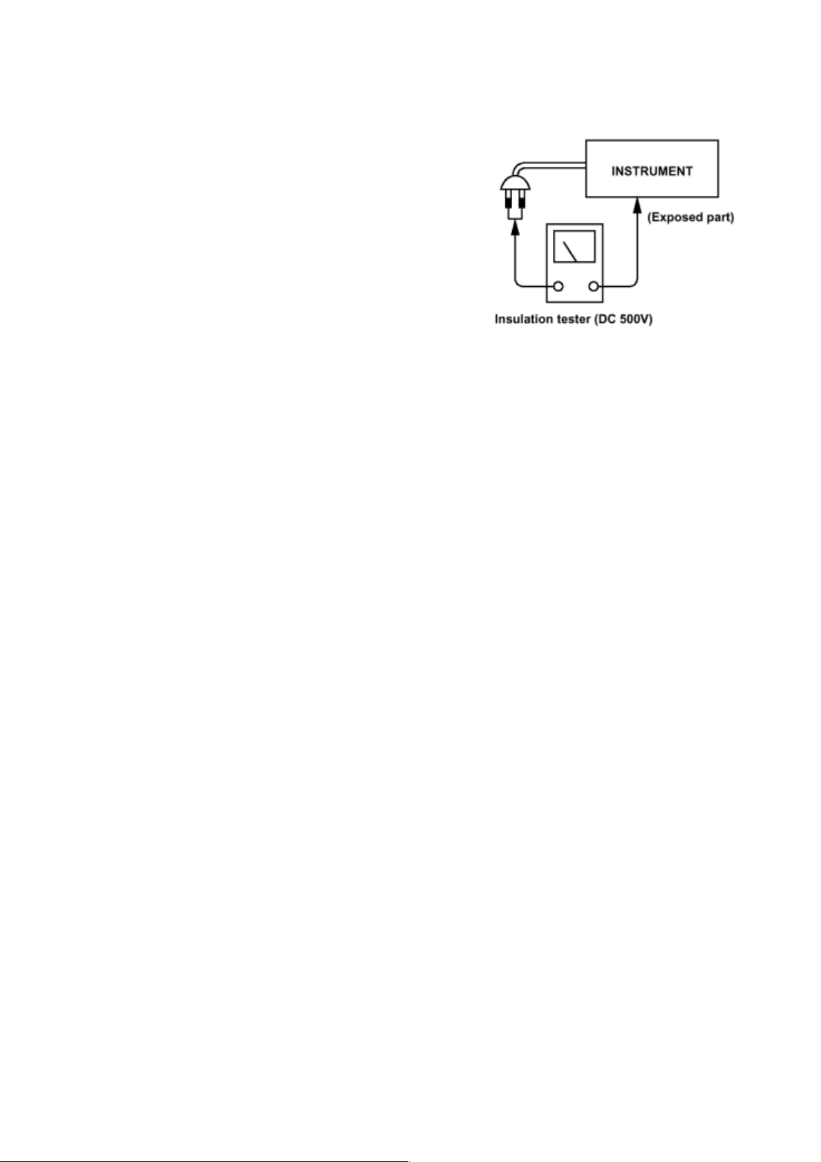
WARNING
Check that exposed parts are acceptably insulated from the supply circuit before returning the repaired
instrument to the customer.
CHECKING METHOD
Measure the resistance value between the both poles of
attachment cup (power supply plug) and the exposed
parts (parts such as covers etc. where the customer can
easily touch) and check that the resistance value is
500k ohms or more.
SAFETY PRECAUTIONS
The following precautions should be observed when servicing.
Since many parts in the unit have special safety related characteristics, always use genuine HITACHI
replacement parts. Especially critical parts in the power circuit block should not be replaced with other makers.
Critical parts are marked with a ! in the circuit diagram and printed wiring board.
Before returning a repaired unit to the customer, the service technician must thoroughly test the unit to
ascertain that it is completely safe to operate without danger of electrical shock.

SPECIFICATIONS
• Audio section
(Power amplifier)
Rated output: Front: 60 W + 60 W (8W/ohms, 20 Hz ~ 20 kHz with 0.08 % T.H.D.)
Centre: 60 W (8W/ohms, 20 Hz ~ 20 kHz with 0.08 % T.H.D.)
Surround: 60 W + 60 W (8W/ohms, 20 Hz ~ 20 kHz with 0.08 % T.H.D.)
Output terminals Front: A or B 8 to 16W/ohms
A + B 16W/ohms or more
Center/Surround: 8 to 16W/ohms
(Analog)
LINE input - PRE OUT
Input sensitivity / input impedance: 200 mV / 47 kW/kohms
Frequency response: 10 Hz ~ 50 kHz: +1, –3 dB
S/N ratio: 92 dB (IHF-A weighted)
Total harmonic distortion: 0.08 % (20 Hz ~ 20 kHz)
Rated output: 1.2 V
PHONO input-REC OUT
Input sensitivity / input impedance: 2.5 mV / 47 kW/kohms
RIAA deviation: ±1 dB (20 Hz ~ 20 kHz)
S/N ratio: 74 dB (IHF-A weighted, with 5 mV input)
Total harmonic distortion: 0.03 % (1 kHz, 3 V)
Rated output / Maximum output: 150 mV / 7V
• Video section
(standard video jacks)
Input/output level and impedance: 1 Vp-p, 75 W/ohms
Frequency response: 5 Hz ~ 10 MHz +1, –3 dB
• Tuner section
[FM] (note: µV at 75 W/ohms, 0 dBf = 1 ¥ 10 W) [AM]
Receiving range: 87.50 MHz ~ 108 MHz (0.05 MHz step) 522 kHz ~ 1611 kHz
Usable sensitivity: 1.0 µV (11.2 dBf) 18 µV
50 dB quieting sensitivity: MONO 1.6 µV (15.3 dBf)
STEREO 23 µV (38.5 dBf)
S/N ratio: MONO 80 dB (IHF-A weighted)
STEREO 75 dB (IHF-A weighted)
Total harmonic distortion: MONO 0.2 % (1 kHz)
STEREO 0.4 % (1 kHz)
• General
Power supply: AC 230 V, 50 Hz (E, EBS), AC 115/230 V, 50/60 Hz (W, WUN)
Power consumption: 180 W
Maximum external dimensions: 434 (W) ¥ 144 (H) ¥ 320 (D) mm
Weight: 7.1 kg
• Remote control unit (RB-DD1S)
Batteries: R6P/AA Type (two batteries)
External dimensions: 54 (W) ¥ 172 (H) ¥ 27.2 (D) mm
Weight: 100 g (including batteries)
• Accessory supplied
Operating instructions, Remote control unit (RB-DD1S),
R6P/AA batteries, AM loop antenna and FM indoor antenna
-15
(9 kHz step) (E, EBS),
522 kHz ~ 1611 kHz
(9 kHz step) (W, WUN)
520 kHz ~ 1710 kHz
(10 kHz step) (W, WUN)
* For purposes of improvement, specifications and design are subject to change without notice.
SERVICE POINTS
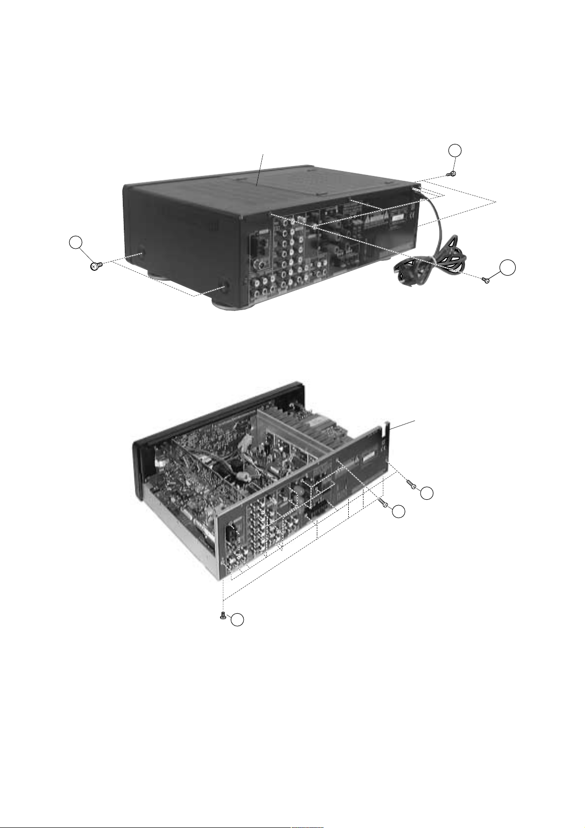
1. Removal of Top Cover
(a)Remove 4 screws 2 from the rear plate.
(b)Remove 2 screws 1 from each side.
Top cover
1
x 2
Fig. 1
2. Removal of the Rear Plate
(a)Remove 23 screws 3 and 1 screw 4 from the rear plate.
(b)Remove 5 screws + from the Bottom Chassis.
1
x 2
2
x 4
Real plate
19
x 5
Fig. 2
3
x 23
4
x 1
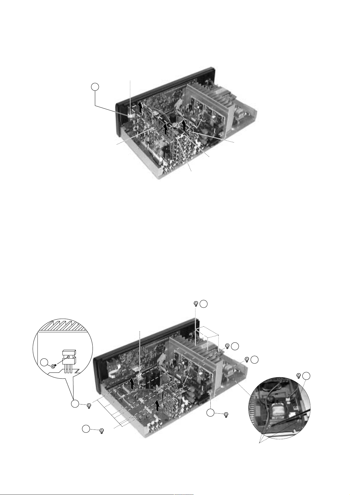
3. Removal of Tuner/DSP/Video/Digital PWB Board
(a)Remove the Flat cable Z at the Tuner PWB.
(b)Gently pull the Tuner/DSP/Video PWB Board upwards to detach 8 connectors from Main PWB Board.
(c)Detach the connector from DSP PWB Board to remove the Digital PWB.
Connectors x 8
Z
Flat cable
Tuner PWB
Video PWB
DSP PWB
Fig. 3
Digital PWB
4. Removal of Heat Sink and Transformer
(a)Invert the Bottom Chassis, remove 2 screws 5 connect to the heat sink. (Fig. 5)
(b)Remove 4 screws 6 and pull the transformer upward together with the Power PWB section.
5. Removal of Power PWB Board
(a)Remove 1 screw 7 from the Bottom Chassis at the side.
(b)Release board from its 3 holding claws (PWB SUPPORT) and gently pull the board free.
6. Removal of Main PWB Board
(a)Detach Flat cable from FL PWB Board.
(b)Remove 6 screws 8 to release the transistors from the heat sink.
(c)Remove 3 screws 9 to release the bracket from the heat sink.
(d)Remove 1 screw ! to release the main PWB from the Bottom Chassis.
x 4
6
Flat Cable x 1
8
8
10
x 6
x 1
Fig. 4
7. Removal of Surround PWB
(a)Remove 5 screws ~ to release surround PWB from the heat sink.
x 5
18
x 1
7
x 1
7
9
x 3
Claws (PWB Support)

8. Removal of Front Panel
(a)Invert the Bottom Chassis and remove 4 screws ".
(b)Remove the Master Vol. & Bass/Treble Knob before remove the Front panel.
5
x 2
12
x 1
Bottom Chassis
Bass/Treble Knob
Master Vol.
Fig. 5
11
x 4
Front Panel
9. Removal of Inner Panel, Power Switch, Phone
Jack and FL PWB
(a)Release the inner panel from the Bottom Chassis by remove 1 screw # (Fig. 5) and 2 screws $.
(b)Remove 11 screws % and 3 nuts to release the FL board.
(c)Remove 2 screws & to release the Power Switch.
(d)Remove 2 screws ( to release the Phone Jack.
15
x 2
Nut x 2
13
x 1
Nut x 1
Inner Panel
16
x 2
13
x 1
14
x 11
Fig. 6
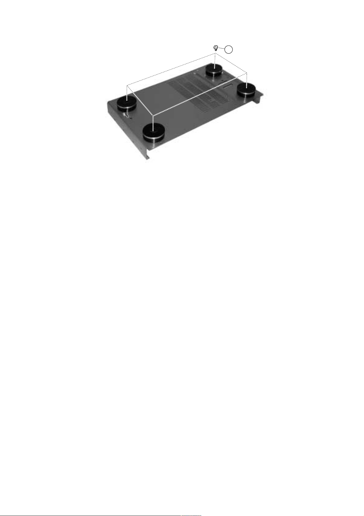
10. Removal of Foot
(a)Remove 4 screws ) to remove foot.
Fig. 7
17
x 4
ADJUSTMENTS
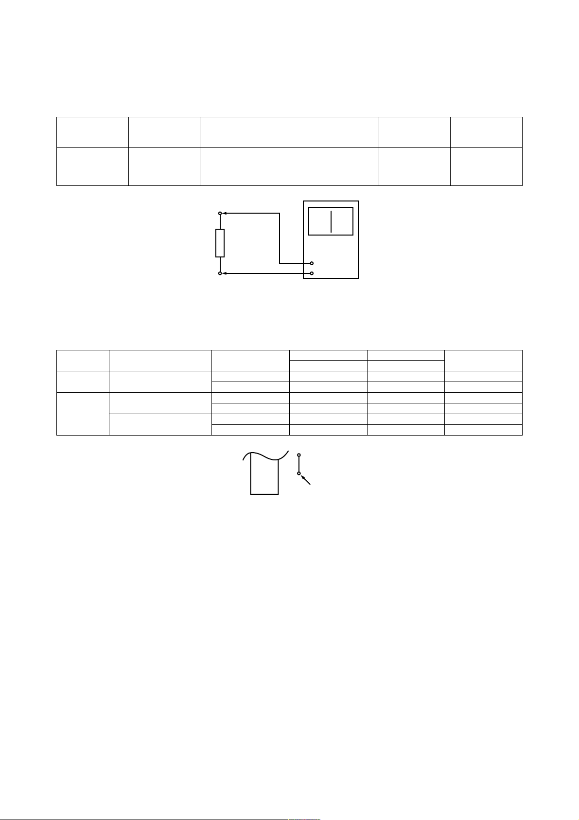
1) FM Discriminator
Measuring instrument and condition.
Input Terminal Output Terminal Measuring Instrument Frequency Adjust Reading
FM Antenna * R22 DC Balance Meter 98.1MHz T4 0±30mV
1kHz, 60 dBµ
22.5kHz dev.
*R22
DC balance meter
2) Voltage of covering (Reference)
Measuring instrument and condition.
Band Destination Frequency Specification Note
Limit (V) Average (V)
FM 50 kHz step 87.50 MHz 1.3 - 3.7 2.3
[E, EBS, W,WUN] 108.00 MHz 6.0 - 9.0 7.5
AM 10 kHz step 520 kHz 0.9 - 1.2 1.0
[W,WUN] 1,710 kHz 6.0 - 9.0 7.5
9 kHz step 522 MHz 0.9 - 1.2 1.0
[E, EBS, W, WUN] 1,611 kHz 6.0 - 9.0 7.5
R51
TEST PT
BL1
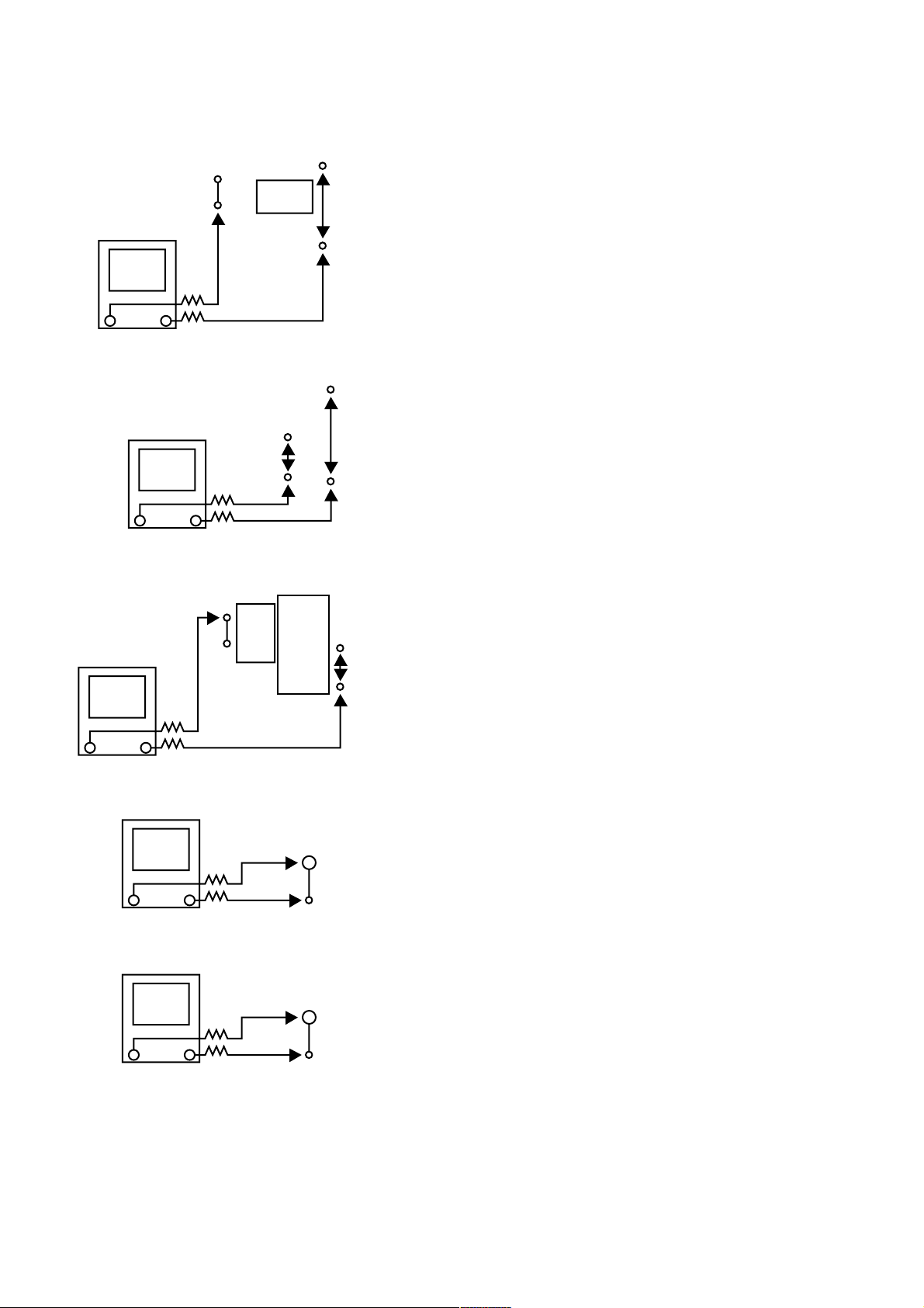
3) Idling voltage (No adjustment is needed)
Test points
a) Front left channel (MAIN PWB)
C522
10K
Ð +
10K
L501
b) Front right channel (MAIN PWB)
JP514
K426
10K
Ð +
10K
JP513
Condition
Master volume : --- (min)
Temperature : 15 ~ 30°C
Reading (SPEC)
1) POWER ON AFTER ONE MIN.
0.5 ~ 2.0 mV
2) STABLE Æ 1 HOUR
0.8 ~ 8 mV
• IF THIS IDLING VOLT - 0.4 mV
R625 (SURROUND LEFT)
R626 (SURROUND RIGHT)
R529 (FRONT LEFT)
R530 (FRONT RIGHT)
R416 (CENTER)
NEED TO CUT AWAY
• IF 2.1 mV
c) Center channel (MAIN PWB)
L401
R429
10K
Ð +
10K
RY401
d) Surr left channel (SURR PWB)
10K
+Ð
10K
e) Surr right channel (SURR PWB)
NEED TO ADD ABOVE RESISTOR
(IF DON'T HAVE ABOVE RESISTOR)
JP407
R639
10K
+Ð
10K
R640
 Loading...