

Page 1
MODEL DEMOLITION HAMMER
MODÈLE MARTEAU PIQUEUR
MODELO MARTILLO DEMOLEDOR
H 60MA • H 60MB
INSTRUCTION MANUAL AND SAFETY INSTRUCTIONS
WARNING
Improper and unsafe use of this power tool can result in death or serious bodily
injury!
This manual contains important information about product safety. Please read
and understand this manual before operating the power tool. Please keep this
manual available for others before they use the power tool.
MODE D’EMPLOI ET INSTRUCTIONS DE SECURITE
AVERTISSEMENT
Une utilisation incorrecte et dangereuse de cet outil motorisé peut entraîner la
mort ou de sérieuses blessures corporelles!
Ce mode d’emploi contient d’importantes informations à propos de la sécurité
de ce produit. Prière de lire et de comprendre ce mode d’emploi avant d’utiliser
l’outil motorisé. Garder ce mode d’emploi à la disponibilité des autres utilisateurs
avant qu’ils utilisent l’outil motorisé.
MANUAL DE INSTRUCCIONES E INSTRUCCIONES DE SEGURIDAD
ADVERTENCIA
¡La utilización inapropiada e insegura de esta herramienta eléctrica puede resultar
en lesiones serias o en la muerte!
Este manual contiene información importante sobre la seguridad del producto.
Lea y comprenda este manual antes de utilizar la herramienta eléctrica. Guarde
este manual para que puedan leerlo otras personas antes de que utilicen la
herramienta eléctrica.
DOUBLE INSULATION
DOUBLE ISOLATION
AISLAMIENTO DOBLE
Page 2

English
English
IMPORTANT INFORMATION ................. 3
MEANINGS OF SIGNAL WORDS .......... 3
SAFETY ....................................................... 4
GENERAL SAFETY RULES .................... 4
SPECIFIC SAFETY RULES AND
SYMBOLS ......................................... 6
DOUBLE INSULATION FOR SAFER
OPERATION ...................................... 8
FUNCTIONAL DESCRIPTION .................... 9
NAME OF PARTS ................................... 9
SPECIFICATIONS .................................... 9
Français
INFORMATIONS IMPORTANTES ........ 18
SIGNIFICATION DES MOTS
D’AVERTISSEMENT ....................... 18
SECURITE ................................................. 19
REGLES GENERALE DE SECURITE .... 19
REGLES DE SECURITE SPECIFIQUES
ET SYMBOLES ................................ 21
DOUBLE ISOLATION POUR UN
FONCTIONNEMENT PLUS SUR .... 23
DESCRIPTION FONCTIONNELLE ............ 24
NOM DES PARTIES .............................. 24
SPECIFICATIONS .................................. 24
TABLE DES MATIERES
CONTENTS
Page Page
Page Page
ASSEMBLY ............................................... 10
OPERATION .............................................. 12
APPLICATIONS ..................................... 12
PRIOR TO OPERATION ........................ 12
HOW TO USE THE DEMOLITION
HAMMER ........................................ 13
MAINTENANCE AND INSPECTION ........ 14
ACCESSORIES ......................................... 16
STANDARD ACCESSORIES ................. 16
OPTIONAL ACCESSORIES .................. 16
PARTS LIST .............................................. 48
ASSEMBLAGE .......................................... 25
FONCTIONNEMENT ................................ 27
APPLICATIONS ..................................... 27
AVANT L’UTILISATION ........................ 27
COMMENT UTILISER LE MARTEAU
PIQUEUR ......................................... 28
ENTRETIEN ET INSPECTION .................. 29
ACCESSOIRES ......................................... 31
ACCESSOIRES STANDARD ................. 31
ACCESSOIRES SUR OPTION .............. 31
LISTA DES PIÈCES ....................................
48
Español
INFORMACIÓN IMPORTANTE ............ 33
SIGNIFICADO DE LAS PALABRAS DE
SEÑALIZACIÓN .............................. 33
SEGURIDAD ............................................. 34
NORMAS GENERALES
DE SEGURIDAD .............................. 34
NORMAS Y SÍMBOLOS ESPECÍFICOS
DE SEGURIDAD .............................. 36
AISLAMIENTO DOBLE PARA OFRECER
UNA OPERACIÓN MÁS SEGURA . 38
DESCRIPCIÓN FUNCTIONAL .................. 39
NOMENCLATURA ................................ 39
ESPECIFICACIONES ............................. 39
2
Página Página
ÍNDICE
MONTAJE ................................................. 40
OPERACIÓN ............................................. 42
APLICACIONES ..................................... 42
ANTES DE LA OPERACIÓN ................. 42
FORMA DE USAR EL MARTILLO
DEMOLEDOR .................................. 43
MANTENIMIENTO E INSPECCIÓN ......... 44
ACCESORIOS ........................................... 46
ACCESORIOS ESTÁNDAR ................... 46
ACCESORIOS OPCIONALES ............... 46
LEATA DE PIEZAS .................................... 48
Page 3

English
IMPORTANT INFORMATION
Read and understand all of the operating instructions, safety precautions and warnings in
the Instruction Manual before operating or maintaining this power tool.
Most accidents that result from power tool operation and maintenance are caused by the
failure to observe basic safety rules or precautions. An accident can often be avoided by
recognizing a potentially hazardous situation before it occurs, and by observing appropriate
safety procedures.
Basic safety precautions are outlined in the “SAFETY” section of this Instruction Manual
and in the sections which contain the operation and maintenance instructions.
Hazards that must be avoided to prevent bodily injury or machine damage are identified by
WARNINGS on the power tool and in this Instruction Manual.
Never use this power tool in a manner that has not been specifically recommended by
HITACHI, unless you first confirm that the planned use will be safe for you and others.
MEANINGS OF SIGNAL WORDS
WARNING indicates a potentially hazardous situations which, if ignored, could result in
serious personal injury.
CAUTION indicates a hazardous situations which, if ignored, could result in moderate
personal injury, or could cause machine damage.
NOTE emphasizes essential information.
3
Page 4

English
SAFETY
GENERAL SAFETY RULES
WARNING: Read and understand all instructions.
Failure to follow all instructions listed below, may result in electric
shock, fire and/or serious personal injury.
SAVE THESE INSTRUCTIONS
1. Work Area
(1) Keep your work area clean and well lit. Cluttered benches and dark areas invite
accidents.
(2) Do not operate power tools in explosive atmospheres, such as in the presence of
flammable liquids, gases, or dust. Power tools create sparks which may ignite the
dust of fumes.
(3) Keep bystanders children, and visitors away while operating a power tool.
Distractions can cause you to lose control.
2. Electrical Safety
(1) Double Insulated tools are equipped with a polarized plug (one blade is wider than
the other.) This plug will fit in a polarized outlet only one way. If the plug does not fit
fully in the outlet, reverse the plug. If it still does not fit, contact a qualified electrician
to install a polarized outlet. Do not change the plug in any way. Double Insulation
eliminates the need for the three wire grounded power cord and grounded power
supply system.
(2) Avoid body contact with grounded surfaces such as pipes, radiators, ranges and
refrigerators. There is an increased risk of electric shock if your body is grounded.
(3) Don’t expose power tools to rain or wet conditions. Water entering a power tool will
increase the risk of electric shock.
(4) Do not abuse the cord. Never use the cord to carry the tools or pull the plug from a
receptacle. Keep cord away from heat, oil, sharp edges or moving parts. Replace
damaged cords immediately. Damaged cords increase the risk of electric shock.
(5) When operating a power tool outside, use an outdoor extension cord marked “W-A”
or “W”. These cords are rated for outdoor use and reduce the risk of electric shock.
3. Personal Safety
(1) Stay alert, watch what you are doing and use common sense when operating a power
tool. Do not use tool while tired or under the influence of drugs, alcohol, or medication.
A moment of inattention while operating power tools may result in serious personal
injury.
(2) Dress properly. Do not wear loose clothing or jewelry. Contain long hair. Keep your
hair, clothing and gloves away from moving parts. Loose clothes, jewelry, or long
hair can be caught in moving parts.
(3) Avoid accidental starting. Be sure switch is off before plugging in. Carrying tools with
your finger on the switch or plugging in tools that have the switch on invites accidents.
4
Page 5

English
(4) Remove adjusting keys or wrenches before turning the tool on. A wrench or a key that
is left attached to a rotating part of the tool may result in personal injury.
(5) Do not overreach. Keep proper footing and balance at all times. Proper footing and
balance enables better control of the tool in unexpected situations.
(6) Use safety equipment. Always wear protective glasses. Dust mask, nonskid safety shoes,
hard hat, or ear plugs must be used for appropriate conditions.
4. Tool Use and Care
(1) Use clamps or other practical way to secure and support the workpiece to a stable
platform. Holding the work by hand or against your body is unstable and may lead to
loss of control.
(2) Do not force tool. Use the correct tool for your application. The correct tool will do the
job better and safer at the rate for which it is designed.
(3) Do not use tool if switch does not turn it on or off. Any tool that cannot be controlled
with the switch is dangerous and must be repaired.
(4) Disconnect the plug form the power source before making any adjustments, changing
accessories, or storing the tool. Such preventive safety measures reduce the risk of
starting the tool accidentally.
(5) Store idle tools out of reach of children and other untrained persons. Tools are dangerous
in the hand of untrained users.
(6) Maintain tools with care. Keep cutting tools sharp and clean. Properly maintained tools,
with sharp cutting edges are less likely to bind and are easier to control.
(7) Check for misalignment or binding of moving parts, breakage of parts, and any other
condition that may affect the tools operation. If damaged, have the tool serviced before
using. Many accidents are caused by poorly maintained tools.
(8) Use only accessories that are recommended by the manufacturer for your model.
Accessories that may be suitable for one tool, may become hazardous when used on
another tool.
5. Service
(1) Tool service must be performed only by qualified repair personnel. Service or
maintenance performed by unqualified personnel could result in a risk of injury.
(2) When servicing a tool, use only identical replacement parts. Follow instructions in the
Maintenance section of this manual. Use of unauthorized parts or failure to follow
Maintenance Instruction may create a risk of electric shock or injury.
5
Page 6

English
SPECIFIC SAFETY RULES AND SYMBOLS
1. Hold tools by insulated gripping surfaces when performing an operation where the
tool may contact hidden wiring or its own cord. Contact with a “live” wire will make
exposed metal parts of the tool “live” and shock the operator.
2. Wear ear plugs when using the tool for extended periods. Prolonged exposure to high
intensity noise can cause hearing loss.
3. Never touch moving parts.
Never place your hands, fingers or other body parts near the tool’s moving parts.
4. Never operate without all guards in place.
Never operate this tool without all guards or safety features in place and in proper
working order. If maintenance or servicing requires the removal of a guard or safety
feature, be sure to replace the guard or safety feature before resuming operation of the
tool.
5. Use right tool.
Don’t force small tool or attachment to do the job of a heavy-duty tool.
Don’t use tool for purpose not intended —for example— don’t use circular saw for
cutting tree limbs or logs.
6. Never use a power tool for applications other than those specified.
Never use a power tool for applications other than those specified in the Instruction
Manual.
7. Handle tool correctly.
Operate the tool according to the instructions provided herein. Do not drop or throw the
tool. Never allow the tool to be operated by children, individuals unfamiliar with its
operation or unauthorized personnel.
8. Keep all screws, bolts and covers tightly in place.
Keep all screws, bolts, and plates tightly mounted. Check their condition periodically.
9. Do not use power tools if the plastic housing or handle is cracked.
Cracks in the tool’s housing or handle can lead to electric shock. Such tools should not
be used until repaired.
10. Blades and accessories must be securely mounted to the tool.
Prevent potential injuries to youself or others. Blades, cutting implements and accessories
which have been mounted to the tool should be secure and tight.
11. Keep motor air vent clean.
The tool’s motor air vent must be kept clean so that air can freely flow at all times. Check
for dust build-up frequently.
12. Operate power tools at the rated voltage.
Operate the power tool at voltages specified on its nameplate.
If using the power tool at a higher voltage than the rated voltage, it will result in
abnormally fast motor revolution and may damage the unit and the motor may burn
out.
13. Never use a tool which is defective or operating abnormally.
If the tool appears to be operating unusually, making strange noises, or otherwise appears
defective, stop using it immediately and arrange for repairs by a Hitachi authorized
service center.
14. Never leave tool running unattended. Turn power off.
Don’t leave tool until it comes to a complete stop.
6
Page 7

English
15. Carefully handle power tools.
Should a power tool be dropped or struck against hard materials inadvertently, it may
be deformed, cracked, or damaged.
16. Do not wipe plastic parts with solvent.
Solvents such as gasoline, thinner benzine, carbon tetrachloride, and alcohol may
damage and crack plastic parts. Do not wipe them with such solvents.
Wipe plastic parts with a soft cloth lightly dampened with soapy water and dry
thoroughly.
17. NEVER touch the tool bit with bare hands after operation.
18. NEVER wear gloves made of stuff liabel to roll up such as cotton, wool, cloth or string,
etc.
19. ALWAYS attach the side handle and securely grip the Demolition Hammer.
20. ALWAYS be careful with buried objict such as an underground wiring.
Touching these active wiring or electric cable with this tool, you may receive an electric
shock.
Comfirm if there are any buried object such as electric cable within the wall, floor or
ceiling where you are going to operate here after.
21. Definitions for symbols used on this tool
V ............volts
Hz .......... hertz
A ............ amperes
no ......... no load speed
W ........... watt
........... Class II Construction
---/min ... revolutions per minute
7
Page 8

English
DOUBLE INSULATION FOR SAFER OPERATION
To ensure safer operation of this power tool, HITACHI has adopted a double insulation
design. “Double insulation “ means that two physically separated insulation systems have
been used to insulate the electrically conductive materials connected to the power supply
from the outer frame handled by the operator. Therefore, either the symbol “ ” or the
words “Double insulation” appear on the power tool or on the nameplate.
Although this system has no external grounding, you must still follow the normal electrical
safety precautions given in this Instruction Manual, including not using the power tool in
wet environments.
To keep the double insulation system effective, follow these precautions:
䡬 Only HITACHI AUTHORIZED SERVICE CENTER should disassemble or assemble this
power tool, and only genuine HITACHI replacement parts should be installed.
䡬 Clean the exterior of the power tool only with a soft cloth moistened with soapy water,
and dry thoroughly.
Never use solvents, gasoline or thinners on plastic components; otherwise the plastic
may dissolve.
SAVE THESE INSTRUCTIONS
AND
MAKE THEM AVAILABLE TO
OTHER USERS OF THIS TOOL!
8
Page 9
English
FUNCTIONAL DESCRIPTION
NOTE:
The information contained in this Instruction Manual is designed to assist you in the
safe operation and maintenance of the power tool.
Some illustrations in this Instruction Manual may show details or attachments that differ
from those on your own power tool
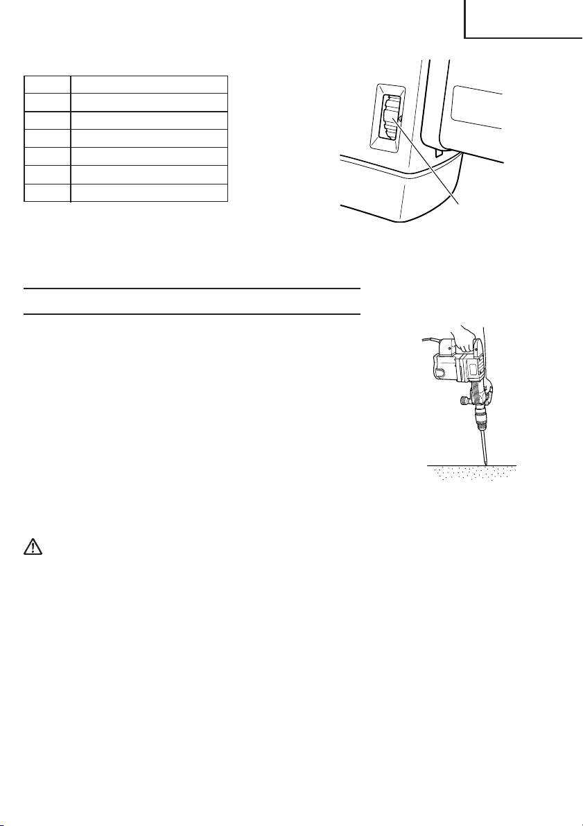
NAME OF PARTS
Front Cap
Grip (B)
Grip (A)
Housing
Brush Cap
(Under the Tail Cover)
Fig. 1
Side
Handle
Nameplate
Stopper
Trigger Switch
Dial (H 60MB)
Tail Cover
SPECIFICATIONS
Model H 60MA H 60MB
Motor Single-Phase, Series Commutator Motor
Power Source Single-Phase, 115V AC 60Hz
Current 11.9A
Full-load Impact Rate 1600/min. 900 – 1600/min.
Weight 23.1 lbs (10.5 kg)
9
Page 10
English
ASSEMBLY
CAUTION: To prevent accidents, make
sure to turn the switch off and
disconnect the plug from the
receptacle.
NOTE:
When using tools such as bull points,
cutters, etc., make sure to use the genuine
parts designated by our company.
1. Installing Tools
(1) Clean the shank portion of the tool.
(2) As shown in Fig. 2, pull grip (A) in the
direction of A, and insert the tool into a
hole of the front cap while turning in the
direction of B.
(3) Adjust the groove position while turning
the tool, and furthermore insert it until it
hits the end of the hole.
(4) Return grip (A) to its original position, pull
the tool to make sure it is locked
completely. (Fig. 3)
2. Deciding Working Position of Tool
The tool can be turned every 30 degrees
and can be fixed at the position of 12
steps.
(1) As shown in Fig. 4, the blade angle can
be freely changed if the grip (A) is turned
in the direction of B in a state where grip
(B) is turned 60 degrees in the direction
of A.
(2) As shown in Fig. 5, if grip (B) is turned 60
degrees in the direction of A, the holding
part of the tool automatically turns 30
degrees. If this action is repeated, the
blade angle of the tool can be changed
by every 30 degrees.
(3) Release grip (B) and turn the tool, and
make sure that it is locked completely.
3. Removing Tool
As shown in Fig. 2, pull grip (A), and pull
out the tool while furthermore turned in
the direction of B.
Tool
Shank
A
A
Front Cap
Fig. 2
Fig. 3
B
Grip (B)
Fig. 4
Grip (B)
Fig. 5
Grip (A)
A
Grip (A)
B
10
Page 11
4. Move the side handle
The side handle can be fixed at any
desired position; 360 degrees, and can
also be fixed at any position in the backand-forth direction.
(1) Loosen the handle by turning the grip in
the direction of A as shown in Fig. 6.
(2) Adjust it to a position where vertical (up-
and-down) operation can be facilitated as
illustrated in Fig. 7, Fig. 8, and Fig. 9.
(3) Turn the grip in the direction of B and
fix the handle.
English
Grip
Fig. 6 Fig. 7
Fig. 8 Fig. 9
11
Page 12
English
OPERATION
APPLICATIONS
䡬 Demolishing concrete, chiseling concrete, grooving, bar cutting, and driving piles.
Application examples:
Installation of piping and wiring, sanitary facility installation, machinery installation,
water supply and drainage work, interior jobs, harbor facilities and other civil engineering
work.
PRIOR TO OPERATION
1. Power source
Ensure that the power source to be utilized conforms to the power source requirements
specified on the product nameplate.
2. Power switch
Ensure that the switch is in the OFF position. If the plug is connected to a receptacle
while the switch is in the ON position, the power tool will start operating immediately
and can cause serious injury.
3. Extension cord
When the work area is far away from the power source, use an extension cord of
sufficient thickness and rated capacity. The extension cord should be kept as short as
practicable.
WARNING: Damaged cord must be replaced or repaired.
4. Check the receptacle
If the receptacle only loosely accepts the plug, the receptacle must be repaired. Contact
a licensed electrician to make appropriate repairs.
If such a fautly receptacle is used, it may cause overheating, resulting in a serious
hazard.
5. Confirming condition of the environment:
Confirm that the work site is placed under appropriate conditions conforming to
prescribed precautions.
6. Select the number of strikes (applicable only to H60MB) (Fig. 10)
CAUTION: Do not make any adjustment of the dial during operation. Holding the main
body with one hand can swing you around, resulting in an injury.
This machine has an electronic controlled circuit built-in, enabling stepless regulation
of the number of strikes. Make the most of this machine by adjusting the dial according
to the working contents; chiseling, demolishing, or the quality of the material to be
chiseling or demolishing.
The scale “1” of the dial is for the minimum speed with 900 strikes per minute, and the
scale “6” is for the maximum speed with 1600 strikes per minute.
12
Page 13
Standard number of strikes
Dial Number of strikes/min.
6 1600
5 1540
4 1420
3 1280
2 1080
1 900
Fig. 10 (H 60MB)
Dial
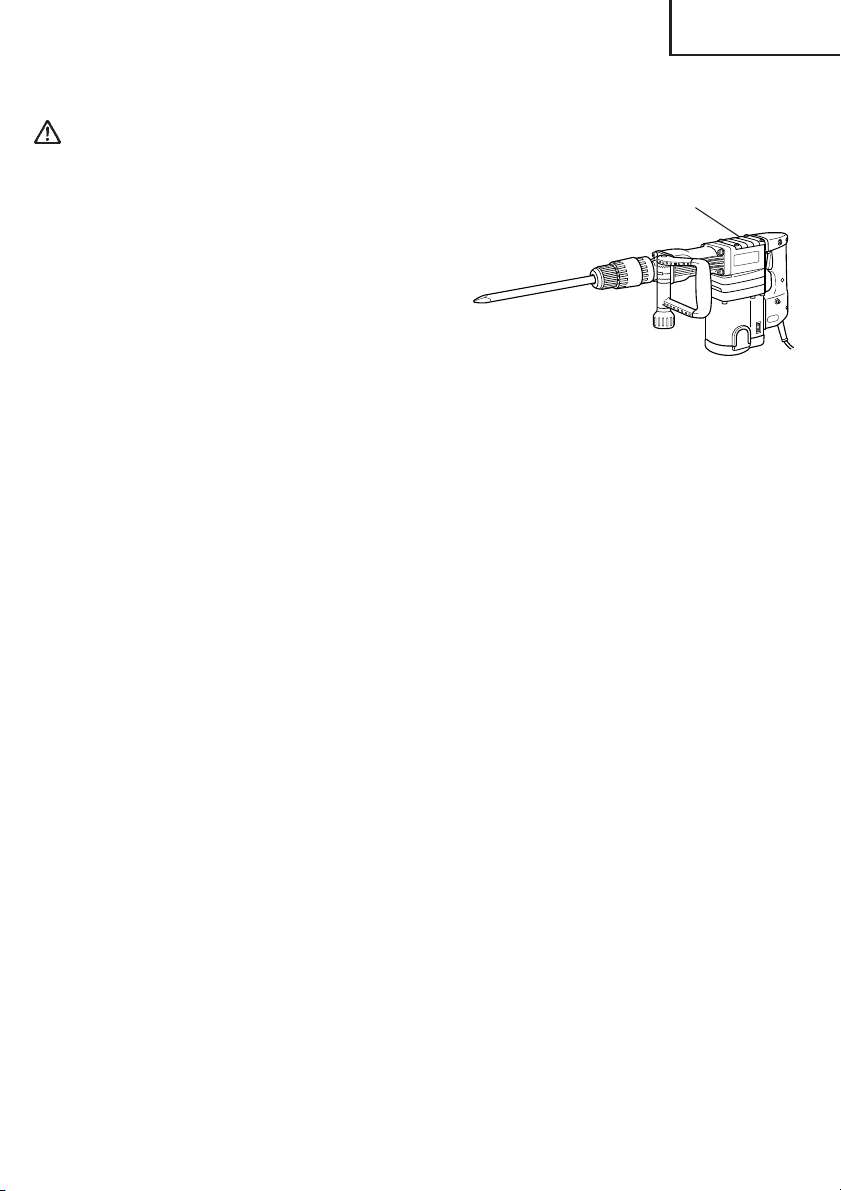
HOW TO USE THE DEMOLITION HAMMER
1. After placing the tip of the tool on concrete surface, switch
ON.
The switch can be turned ON if the trigger is pulled and OFF
when it is released.
If the stopper is pressed while the trigger for the switch is
pulled, even if your finger is released from the trigger, the
switch remains ON - convenient for continuous operation.
To turn the switch OFF, pull the trigger again, and then the
stopper comes off.
2. By utilizing the empty weight of the machine and by firmly
holding the hammer by both hands, you can effectively control
the subsequent recoil motion.
Proceed at a moderate work-rate, the use of too much pushing force will impair efficiency.
Fig. 11
English
CAUTION: After long time of use, the front cover becomes hot.
Therefore, be careful not to burn your hands.
13
Page 14
English
74
MAINTENANCE AND INSPECTION
WARNING: Be sure to switch power OFF and disconnect the plug from the
receptacle during maintenance and inspection.
1. Inspecting the tool
Since use of a dull tool will degrade efficiency and cause possible motor malfunction,
sharpen or replace the tool as soon as abrasion is noted.
2. Inspecting the mounting screws
Regularly inspect all mounting screws and ensure that they are properly tightened.
Should any of the screws be loosened, retighten them immediately.
WARNING: Using this demolition hammer with loosen screws is extremely
dangerous.
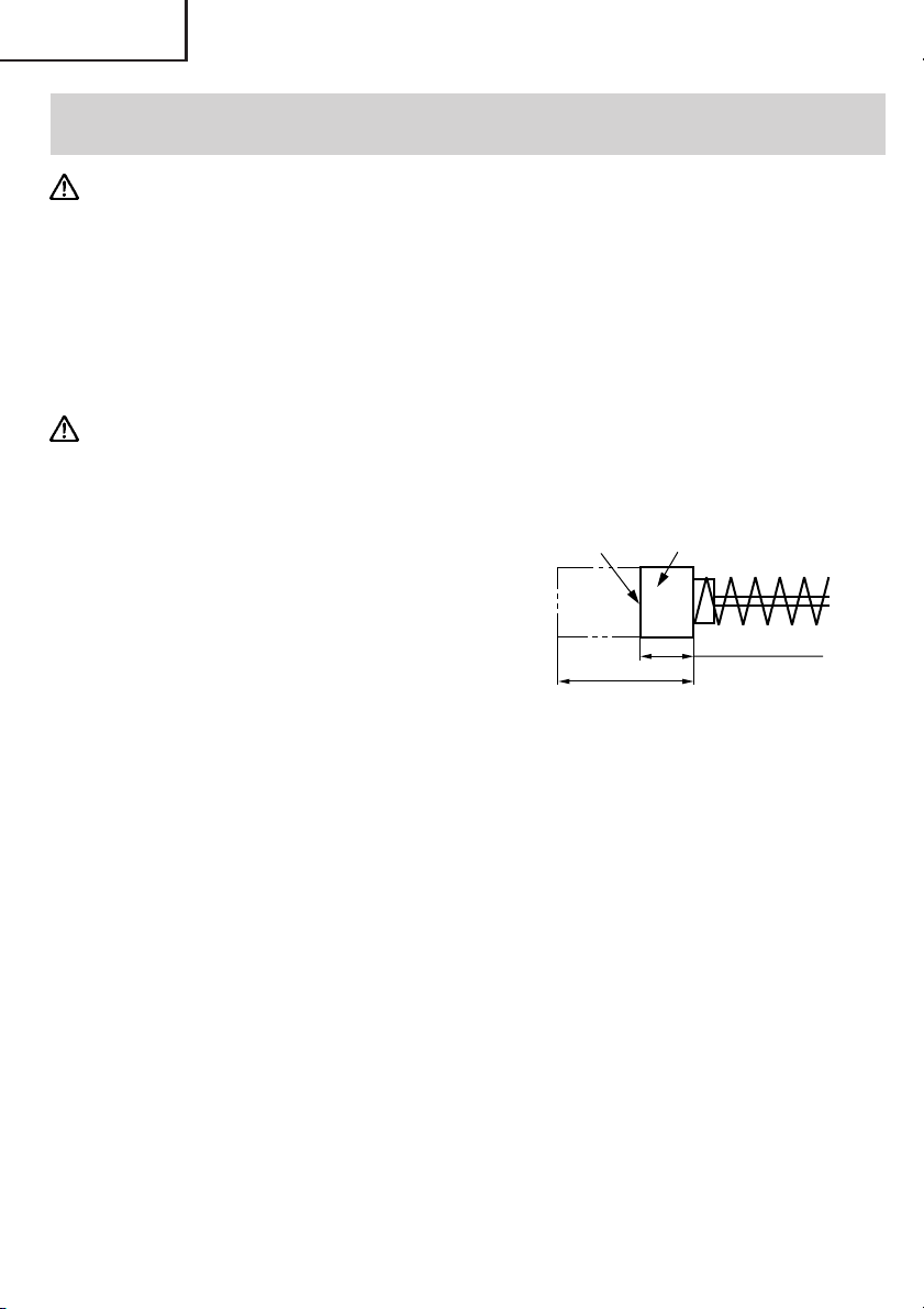
3. Inspecting the carbon brushes (Fig. 12)
The Motor employs carbon brushes which
are consumable parts. When they become
worn to or near the “wear limit”, it could
result in motor trouble. When an auto-stop
carbon brush is equipped, the motor will
stop automatically. At that time, replace
both carbon brushes with new ones which
have the same carbon brush Numbers
shown in the figure. In addition, always
keep carbon brushes clean and ensure that
they slide freely within the brush holders.
NOTE: Use HITACHI carbon brush No. 74 indicated in Fig. 12.
Wear limit
0.67” (17 mm)
No. of carbon
brush
0.28” (7 mm)
Fig. 12
4. Replacing carbon brushes (Refer to figure for name of parts)
Loosen the set screw then remove the tail cover. By loosening the brush caps, the
carbon brushes can be removed. After fitting new carbon brushes, properly retighten
the brush caps and mount the tail cover.
5. Grease replacement
This machine is of fully oil sealed construction to protect against dust incursion and to
prevent lubricant leakage. This machine can be used without grease replenishment for
an extended period of time. However, perform the grease replacement to extend the
service life. Replace the grease as described below.
(1) Grease Replacement Period
Inspect the grease amount according to the timing replacement period of the carbon
brush. (See item 3 in the section MAINTENANCE AND INSPECTION.)
Ask for grease replacement at the nearest authorized Hitachi Service Center.
In the case that you are forced to change the grease by yourself, please follow the
following points.
14
Page 15
English
(2) How to replace grease
CAUTION:
䡬 Before replacing the grease, turn the power off and pull out the plug from the receptacle.
1 Disassenble the crank cover and thorougly
wipe off the old grease inside.
2 Supply 2 oz (60g) (the standard volume
to cover the connecting rod) of Hitachi
Electric Hammer Grease A in the crank
case.
3 After replacing the grease, reassemples
the crank cover securely. At this time, do
not damage or lose the oil seal.
NOTE:
䡬 The Hitachi Electric Hammer Grease A is of the low viscosity type. When the grease is
consumed, purchase from the authorized Hitachi Service Center.
䡬 Do not excessively supply the designated amount of grease. Otherwise, the tool should
not operate accurately.
Crank Cover
Fig. 13
6. Service and repairs
All quality power tools will eventually require servicing or replacement of parts because
of wear from normal use. To assure that only authorized replacement parts will be
used, all service and repairs must be performed by a HITACHI AUTHORIZED SERVICE
CENTER, ONLY.
15
Page 16
English
ACCESSORIES
WARNING: Accessories for this power tool are mentioned in this Instruction Manual.
The use of any other attachment or accessory can be dangerous and
could cause injury or mechanical damage.
NOTE:
Accessories are subject to change without any obligation on the part of the HITACHI.
STANDARD ACCESSORIES
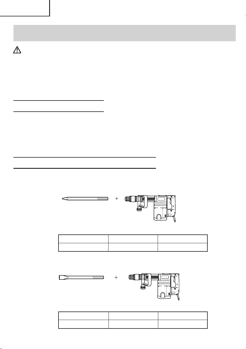
(1) Bull Point (SDS max shank) (Code No. 313471) ................................................................ 1
(2) Case (Code No. 317125) ...................................................................................................... 1
(3) Side Handle (Code No. 317103) .......................................................................................... 1
(4) Allen Wrench (for 8 mm screw) (Code No. 872422) ......................................................... 1
OPTIONAL ACCESSORIES........ sold separately
䡬 Demolitioning
(1) Bull Point (SDS max shank type)
Overall Length 11-1/32" (280 mm) 15-3/4" (400 mm)
Code No. 313471 313472
䡬 Groove digging and edging
(1) Cold chisel (SDS max shank type)
Overall Length 11-1/32" (280 mm) 15-3/4" (400 mm)
Code No. 313473 313474
16
Page 17

䡬 Asphalt Cutting
(1) Cutter (SDS max shank type)
Overall Length 15-3/4" (400 mm)
Code No. 313475
䡬 Scooping Work
(1) Scoop (SDS max shank type)
Overall Length 15-3/4" (400 mm)
Code No. 313476
䡬 Surface Roughing
English
(1) Bushing Tool
(Code No. 313477)
(2) Shank
(Code No. 313479)
䡬 Tamping
(1) Rammer
(Code No. 313478)
(2) Shank
(Code No. 313479)
䡬 Hammer Grease A
70g (in a tube) (Code No. 981840)
30g (in a tube) (Code No. 308471)
NOTE:
Specifications are subject to change without any obligation on the part of the HITACHI.
17
Page 18

Français
INFORMATIONS IMPORTANTES
Lire et comprendre toutes les instructions de fonctionnement, les précautions de sécurité
et les avertissements dans ce mode d’emploi avant d’utiliser ou d’entretenir cet outil
motorisé.
La plupart des accidents causés lors de l’utilisation ou de l’entretien de l’outil motorisé
proviennent d’un non respect des règles ou précautions de base de sécurité. Un accident
peut la plupart du temps être évité si l’on reconnaît une situation de danger potentiel avant
qu’elle ne se produise, et en observant les procédures de sécurité appropriées.
Les précautions de base de sécurité sont mises en évidence dans la section “SECURITE”
de ce mode d’emploi et dans les sections qui contiennent les instructions de fonctionnement
et d’entretien.
Les dangers qui doivent être évités pour prévenir des blessures corporelles ou un
endommagement de la machine sont identifiés par AVERTISSEMENTS sur l’outil motorisé
et dans ce mode d’emploi.
Ne jamais utiliser cet outil motorisé d’une manière qui n’est pas spécifiquement
recommandée par HITACHI sans avoir d’abord vérifié que l’utilisation prévue est sans danger
pour vous et les autres.
SIGNIFICATION DES MOTS D’AVERTISSEMENT
AVERTISSEMENT indique des situations potentiellement dangereuses qui, si elles sont
ignorées, pourraient entraîner de sérieuses blessures personnelles.
PRECAUTION indique des situations dangereuses qui, si elles sont ignorées, pourrait
entraîner de légères blessures personnelles ou endommager la machine.
REMARQUE met en relief des informations essentielles.
18
Page 19

Français
SECURITE
REGLES GENERALE DE SECURITE
AVERTISSEMENT: Lire et coxmprendre toutes les instructions.
Un non respect de toutes les instructions ci-dessous peut
entraîner une électrocution, un incendie et/ou de sérieuses
blessures personnelles.
CONSERVER CES INSTRUCTIONS
1. Zone de travail
(1) Garder la zone de travail propre et bien éclairée. Les établis mal rangés et les zones
sombres invitent aux accidents.
(2) Ne pas utiliser les outils motorisés dans une atmosphère explosive, telle qu’en
présence de liquides inflammables, de gaz ou de poussières. Les outils motorisés
créent des étincelles qui risquent d’enflammer la poussière ou les vapeurs.
(3) Tenir les spectateurs, les enfants et les visiteurs éloignés, lors de l’utilisation de
l’outil motorisé. Une distraction peut faire perdre le contrôle de la machine.
2. Sécurité électrique
(1) Les outils à double isolation sont équipés d’une fiche polarisée (une lame est plus
large que l’autre). Cette fiche ne pénétrera dans une prise secteur polarisée que
dans un sens. Si la fiche ne rentre pas complètement dans la prise, la retourner. Si
elle ne rentre toujours pas, contacter un électricien qualifié pour installer une prise
polarisée. Ne pas modifier la fiche d’aucune façon. La double isolation élimine le
besoin d’un cordon d’alimentation à trois fils et d’un système d’alimentation avec
mises à la terre.
(2) Eviter tout contact corporel avec les surfaces mises à la terre telles que les
canalisations, les radiateurs, les réchauds et les réfrigérateurs. Il y a un risque accru
d’électrocution si son corps est mis à la terre.
(3) Ne pas exposer les outils motorisés à la pluie ou à l’humidité. De l’eau pénétrant à
l’intérieur de l’outil motorisé augmente le risque d’électrocution.
(4) Ne pas maltraiter le cordon d’alimentation. Ne jamais utiliser le cordon pour porter
les outils ou tirer sur la fiche du réceptacle. Garder le cordon à l’écart de la chaleur,
de l’huile, des arêtes coupantes ou des pièces en mouvement. Remplacer les cordons
endommagés immédiatement. Des cordons endommagés augmentent le risque
d’électrocution.
(5) Lors de l’utilisation d’un outil motorisé, utiliser un cordon de rallonge extérieur
marqué “W-A” ou “W”. Ces cordons sont prévus pour une utilisation extérieure et
réduisent les risques d’électrocution.
3. Sécurité personnelle
(1) Rester sur ses gardes, regarder ce que l’on fait et utiliser son sens commun lors de
l’utilisation d’un outil motorisé. Ne pas utiliser un outil en état de fatigue ou sous
l’influence de drogues, d’alcool ou de médicaments. Un moment d’inattention lors
de l’utilisation de l’outil motorisé peut entraîner de sérieuses blessures personnelles.
(2) S’habiller correctement. Ne pas porter des vêtements larges ou des bijoux. Attacher
les cheveux longs. Tenir ses cheveux, vêtements et ses gants éloignés des parties
mobiles. Les vêtements larges, les bijoux et les cheveux longs peuvent se prendre
dans les parties mobiles.
19
Page 20

Français
(3) Eviter tout démarrage accidentel. S’assurer que le l’interrupteur d’alimentation est
sur la position d’arrêt avant de brancher la machine. Transporter l’appareil avec les
doigts sur l’interrupteur d’alimentation ou brancher un outil avec l’interrupteur sur
la position marche invite aux accidents.
(4) Retirer les clefs d’ajustement ou les commutateurs avant de mettre l’outil sous
tension. Une clef qui est laissée attachée à une partie tournante de l’outil peut
provoquer une blessure personnelle.
(5) Ne pas trop présumer de ses forces. Garder en permanence une position et un
équilibre correct. Une position et un équilibre correct permettent un meilleur contrôle
de l’outil dans des situations inattendues.
(6) Utiliser un équipement de sécurité. Toujours porter des lunettes de protection. Un
masque à poussière, des chaussures de sécurité antidérapantes, un chapeau dur et
des bouchons d’oreille doivent être utilisés dans les conditions appropriées.
4. Utilisation de l’outil et entretien
(1) Utiliser un étau ou toutes autres façons de fixer et maintenir la pièce à usiner sur
une plate-forme stable. Tenir la pièce avec la main ou contre son corps est instable
et peut conduire à une perte de contrôle de l’outil.
(2) Ne pas forcer sur l’outil. Utiliser l’outil correct pour l’application souhaitée. L’outil
correct réalisera un meilleur et plus sûr travail dans le domaine pour lequel il a été
conçu.
(3) Ne pas utiliser un outil s’il ne se met pas sous ou hors tension avec un interrupteur.
Un outil qui ne peut pas être commandé avec un interrupteur est dangereux et doit
être réparé.
(4) Déconnecter la fiche de la source d’alimentation avant de réaliser tout ajustement,
changement d’accessoires ou pour ranger l’outil. De telles mesures de sécurité
réduisent le risque que l’outil ne démarre accidentellement.
(5) Ranger les outils inutilisés hors de la portée des enfants et des autres personnes
inexpérimentées. Les outils sont dangereux dans les mains de personnes
inexpérimentées.
(6) Conserver les outils avec soin. Garder les outils de coupe aiguisés et propres. Des
outils bien entretenus, avec des lames coupantes aiguisées risquent moins de se
gripper et sont plus faciles à contrôler.
(7) Vérifier les défauts d’alignement ou grippage des parties mobiles, les ruptures des
pièces et toutes les autres conditions qui peuvent affecter le fonctionnement des
outils. En cas de dommage, faire réparer l’outil avant de l’utiliser. Beaucoup
d’accidents sont causés par des outils mal entretenus.
(8) Utiliser uniquement les accessoires recommandés par le fabricant pour le modèle
utilisé. Des accessoires qui peuvent convenir à un outil, peuvent devenir dangereux
lorsqu’ils sont utilisés avec un autre outil.
5. Réparation
(1) La réparation de l’outil ne doit être réalisée uniquement par un réparateur qualifié.
Une réparation ou un entretien réalisé par un personnel non qualifié peut entraîner
des risques de blessures.
(2) Lors de la réparation d’un outil, utiliser uniquement des pièces de rechange
identiques. Suivre les instructions de la section d’entretien de ce mode d’emploi.
L’utilisation de pièces non autorisées ou un non respect des instructions d’entretien
peut créer un risque d’électrocution ou de blessures.
20
Page 21

Français
REGLES DE SECURITE SPECIFIQUES ET SYMBOLES
1. Tenir les outils par les surfaces de grippage lors de la réalisation d’opération où l’outil
de coupe risque d’entrer en contact avec des câbles cachés ou son propre cordon. Un
contact avec un fil “sous tension” mettra les parties métalliques de l’outil “sous tension”
et électrocutera l’utilisateur.
2. TOUJOURS porter des bouchons d’oreille lors de l’utilisation de l’outil pendant de
longues périodes. Une exposition prolongée à un son de forte intensité peut endommager
l’ouïe de l’utilisateur.
3. Ne jamais toucher les parties mobiles.
Ne jamais placer ses mains, ses doigts ou toute autre partie de son corps près des
parties mobiles de l’outil.
4. Ne jamais utiliser l’outil sans que tous les dispositifs de sécurité ne soient en place.
Ne jamais faire fonctionner cet outil sans que tous les dispositifs et caractéristiques de
sécurité ne soient en place et en état de fonctionnement. Si un entretien ou une réparation
nécessite le retrait d’un dispositif ou d’une caractéristique de sécurité, s’assurer de bien
remettre en place le dispositif ou la caractéristique de sécurité avant de recommencer à
utiliser l’outil.
5. Utiliser l’outil correct
Ne pas forcer sur un petit outil ou accessoire pour faire le travail d’un outil de grande
puissance. Ne pas utiliser un outil pour un usage pour lequel il n’a pas été prévu: par
exemple, ne pas utiliser une scie circulaire pour couper des branches d’arbre ou des
bûches.
6. Ne jamais utiliser un outil motorisé pour des applications autres que celles spécifiées.
Ne jamais utiliser un outil motorisé pour des applications autres que celles spécifiées
dans le mode d’emploi.
7. Manipuler l’outil correctement
Utiliser l’outil de la façon indiquée dans ce mode d’emploi. Ne pas laisser tomber ou
lancer l’outil. Ne jamais permettre que l’outil soit utilisé par des enfants, des personnes
non familiarisées avec son fonctionnement ou un personnel non autorisé.
8. Maintenir toutes les vis, tous les boulons et les couvercles fermement en place.
Maintenir toutes les vis, tous les boulons et les couvercles fermement montés. Vérifier
leurs conditions périodiquement.
9. Ne pas utiliser les outils motorisés si le revêtement de plastique ou la poignée est
fendu.
Des fentes dans le revêtement ou la poignée peuvent entraîner une électrocution. De
tels outils ne doivent pas être utilisés avant d’être réparé.
10. Les lames et les accessoires doivent être fermement montés sur l’outil.
Eviter les blessures potentielles personnelles et aux autres. Les lames, les instruments
de coupe et les accessoires qui ont été montés sur l’outil doivent être fixés et serrés
fermement.
11. Garder propres les évents d’air du moteur
Les évents d’air du moteur doivent être maintenus propres de façon que l’air puisse
circuler librement tout le temps. Vérifier les accumulations de poussière fréquemment.
21
Page 22

Français
12. Utiliser l’outil motorisé à la tension nominale.
Utiliser l’outil motorisé à la tension spécifiée sur sa plaque signalétique.
Si l’on utilise l’outil motorisé avec une tension supérieure à la tension nominale, il en
résultera une rotation anormalement trop rapide du moteur et cela risque d’endommager
l’outil et le moteur risque de griller.
13. Ne jamais utiliser un outil défectueux ou qui fonctionne anormalement.
Si l’outil n’a pas l’air de fonctionner normalement, fait des bruits étranges ou sans cela
paraît défectueux, arrêter de l’utiliser immédiatement et le faire réparer par un centre
de service Hitachi autorisé.
14. Ne jamais laisser fonctionner l’outil sans surveillance. Le mettre hors tension.
Ne pas abandonner l’outil avant qu’il ne soit complètement arrêté.
15. Manipuler l’outil motorisé avec précaution.
Si un outil motorisé tombe ou frappe un matériau dur accidentellement, il risque d’être
déformé, fendu ou endommagé.
16. Ne pas essuyer les parties en plastique avec du solvant.
Les solvants comme l’essence, les diluants, la benzine, le tétrachlorure de carbone et
l’alcool peuvent endommager et fissurer les parties en plastique. Ne pas les essuyer
avec de tels solvants.
Essuyer les parties en plastique avec un chiffon doux légèrement imbibé d’une solution
d’eau savonneuse et sécher minutieusement.
17. NE JAMAIS toucher la mèche avec des mains nues après l’utilisation.
18. NE JAMAIS porter de gants faits d’une matière qui risque de s’enrouler, comme du
coton, de la laine, de la toile ou de la ficelle, etc.
19. TOUJOURS fixer la poignée latérale et tenir le marteau piqueur solidement.
20. TOUJOURS vérifier s’il y a des objets encastrés, par exemple des fils électriques.
Le fait de toucher avec l’outil un fil ou un câble électrique sous tension encastré dans le
mur risque de provoquer une décharge électrique.
Vérifier s’il y des objets encastrés, par exemple un câble électrique, dans le mur, le
plancher ou le planfond avant d’y commencer le travail.
21. Définitions pour les symboles utilisés sur cet outil
V ............. volts
Hz ........... hertz
A ............. ampères
no .......... vitesse sans charge
W ............ watt
............ Construction de classe II
---/min .... tours par minute
22
Page 23

Français
DOUBLE ISOLATION POUR UN FONCTIONNEMENT PLUS SUR
Pour assurer un fonctionnement plus sûr de cet outil motorisé, HITACHI a adopté une
conception à double insolation. “Double isolation” signifie que deux systèmes d’isolation
physiquement séparés ont été utilisés pour isoler les matériaux conducteurs d’électricité
connectés à l’outil motorisé à partir du cadre extérieur manipulé par l’utilisateur. C’est
pourquoi, le symbole “ ” ou les mots “Double insulation” (double isolation) apparaissent
sur l’outil motorisé ou sur la plaque signalétique.
Bien que ce système n’ait pas de mise à terre extérieure, il est quand même nécessaire de
suivre les précautions de sécurité électrique données dans ce mode d’emploi, y-compris
de ne pas utiliser l’outil motorisé dans un environnement humide.
Pour garder le système de double isolation effectif, suivre ces précautions:
䡬 Seuls les CENTRES DE SERVICE AUTORISES HITACHI peuvent démonter et remonter
cet outil motorisé et uniquement des pièces de rechange HITACHI garanties d’origine
doivent être utilisées.
䡬 Nettoyer l’extérieur de l’outil motorisé uniquement avec un chiffon doux légèrement
imbibé d’une solution savonneuse et essuyer minutieusement.
Ne jamais utiliser des solvants, de l’essence ou des diluants sur les parties en plastique;
sinon le plastique risquerait de se dissoudre.
CONSERVER CES INSTRUCTIONS
ET
LES METTRE A LA DISPOSITION
DES AUTRES UTILISATEURS
DE CET OUTIL!
23
Page 24

Français
DESCRIPTION FONCTIONNELLE
REMARQUE:
Les informations contenues dans ce mode d’emploi sont conçues pour assister
l’utilisateur dans une utilisation sans danger et un entretien de l’outil motorisé.
Certaines illustrations dans ce mode d’emploi peuvent montrer des détails ou des
accessoires différents de ceux de l’outil motorisé utilisé.
NOM DES PARTIES
Poignée
latérale
Poignée (B)
Capuchon avant
Poignée (A)
Carter
Tête porte-charbon
(sous le courvercle arrière)
Fig. 1
Plaque
signalétique
Couvercle
arrière
Butée
Gâchette
Molette (H 60MB)
SPECIFICATIONS
Modèle H 60MA H 60MB
Moteur Moteur série monophasé à collecteur
Source d’alimentation Secteur, 115V 60 Hz, monophasé
Courant 11,9A
Nombre de percussions à pleine charge
Poids 23,1 lbs (10,5 kg)
1600/min. 900 – 1600/min.
24
Page 25

ASSEMBLAGE
Français
PRECAUTION :
Pour éviter tout risque d’accident,
s’assurer que l’outil est éteint et débranché
du secteur.
REMARQUE:
Lorsqu’on installe des outils, par exemple
des pointes à béton, des couteaux, etc., bien
veiller à utiliser les pièces d’origine conçues
par notre société.
1. Installation des outils
(1) Nettoyer la section de la queue de l’outil.
(2) Comme indiqué sur la Fig. 2, tirer sur la
poignée (A) dans la direction A, et insérer
l’outil dans l’un des orifices du capuchon
avant rout en tournant dans la direction B.
(3) Régler la position de la rainure tout en
tournant l’outil, et l’insérer encore
davantage jusqu’à ce qu’il touche le fond
de l’orifice.
(4) Ramener la poignée (A) sur sa position
d’origine, tirer sur l’outil et vérifier qu’il est
bloqué à fond. (Fig. 3)
2. Recherche de la position de travail de
l’outil
L’outil peut tourner par paliers de 30 degrés
et il peut être fixé sur l’un de ces 12 paliers.
(1) Comme indiqué sur la Fig. 4, si l’on tourne
la poignée (A) dans le sens B de telle sorte
que la poignée (B) est tournée de 60 degrés
dans le sens A, il sera possible de modifier
librement l’angle de la lame sur n’importe
quelle position.
(2) Comme indiqué sur la Fig. 5, si l’on tourne
la poignée (B) de 60 degrés dans la direction
A, la section qui supporte l’outil tourne
automatiquement de 30 degrés. Si l’on
repète cette opération, il est possible de
modifier l’angle de la lame par paliers de
30 degrés.
(3) Libérer la poignée (B) et tourner l’outil, et
vérifier qu’il est bloqué à fond.
Poignée (A)
Queue
d’outil
Capuchon avant
AB
Poignée (B)
A
A
Fig. 2
Fig. 3
Poignée (A)
Fig. 4
Poignée (B)
Fig. 5
B
25
Page 26

Français
3. Retrait de l’outil
Comme indiqué sur la Fig. 2, tirer sur la
poignée (A) et sortir l’outil rout en tournant
dans la direction B.
4. Déplacer la poignée latérale.
La poignée latérale peut se fixer à n’importe
quelle position sur 360 degrés, et elle peut
également être fixée sur n’importe quelle
position en sens avant et arrière.
(1)
Desserrer la poignée en tournant la saisie
dans le sens de A comme indiqué à la Fig. 6.
(2)
Régler la poignée à une position facilitant le
fonctionnement vertical (de haut en bas),
comme indiqué à la Fig. 7, la Fig. 8 et la Fig. 9.
(3) Tourner la saisie dans le sens de B et fixer
la poignée.
Poignée
Fig. 6 Fig. 7
Fig. 8 Fig. 9
26
Page 27

Français
FONCTIONNEMENT
APPLICATIONS
䡬 Broyage du béton, burinage, rainurage, coupe de barres, et enfoncement de pieux.
Exemples d’application:
Installation de tuyautage et de câblage, installation de facilités sanitaires, de machinerie,
d’alimentation d’eau et de drainage, travaux intérieurs, facilités de port et autres travaux
de génie civil.
AVANT L’UTILISATION
1. Source d’alimentation
S’assurer que la source d’alimentation qui doit être utilisée est conforme à la source
d’alimentation requise spécifiée sur la plaque signalétique du produit.
2. Interrupteur d’alimentation
S’assurer que l’interrupteur est sur la position OFF (arrêt). Si la fiche est connectée sur
une prise alors que l’interrupteur est sur la position ON (marche), l’outil motorisé
démarrera immédiatement risquant de causer de sérieuses blessures.
3. Cordon prolongateur
Quand la zone de travail est éloignée de la source d’alimentation, utiliser un cordon
prolongateur d’épaisseur et de capacité nominale suffisante. Le cordon prolongateur
doit être aussi court que possible.
AVERTISSEMENT: Tout cordon endommagé devra être remplacé ou réparé.
4. Vérifier la prise
Si la prise reçoit la fiche avec beaucoup de jeu, elle doit être réparée. Contacter un
électricien licencié pour réaliser les réparations nécessaires.
Si une telle prise défectueuse est utilisée, elle peut causer une surchauffe entraînant
des dangers sérieux.
5. Vérification des conditions d’environnement
Vérifier que l’état de l’aire de travail est conforme aux précautions.
6. Sélectionner le nombre de frappes (uniquement avec le modèle H60MB)
(Fig. 10)
PRECAUTION :
N’effectuer aucun réglage de la molette pendant le fonctionnement. L’outil risque de
pivoter si on le tient d’une seule main, ce qui pourrait provoquer un accident.
27
Page 28

Français
L’outil possède un circuit de commande électronique incorporé qui permet de régler le
nombre de frappes directement. Pour profiter au maximum des possibilités de l’outil,
régler la molette en fonction du travail: burinage, démolition, ou de la qualité du matériau
à buriner ou à démolir.
La graduation “1” de la molette représente la vitesse minimale avec 900 frappes par
minute, et la graduation “6” de la molette représente la vitesse maximale avec 1600
frappes par minute.
Nombre de frappes standard
Molette Nombre de frappes/mn
6 1600
5 1540
4 1420
3 1280
2 1080
1 900
Fig. 10 (H 60MB)
Molette
COMMENT UTILISER LE MARTEAU PIQUEUR
1. Après avoir placé la pointe de l’outil sur la surface du béton,
brancher l’outil sur ON.
L’interrupteur s’enclenche lorsqu’on tire la gâchette et il se
coupe quand on relâche la gâchette.
Si l’on appuie sur la butée pendant qu’on appuie sur la
gâchette de l’interrupteur, l’interrupteur reste enclenché,
même si on relâche le doigt de la gâchette, ce qui est pratique
pour un fonctionnement continu. Pour couper l’interrupteur,
tirer à nouveau sur la gâchette; la butée se coupe.
2. En utilisant le poids à vide de la machine et en maintenant
fermement le marteau avec les deux mains, le mouvement
de recul peut être effectivement contrôle. Procéder avec un
régime modéré; l’utilisation de trop de poussée pourrait
réduire l’efficacité.
PRECAUTION : Après une utilisation prolongée, le couvercle avant devient chaud. Faire
attention de ne pas se brûler les mains.
28
Fig. 11
Page 29

Français
74
ENTRETIEN ET INSPECTION
AVERTISSEMENT: S’assurer de mettre l’interrupteur d’alimentation sur la
position OFF et de déconnecter la fiche de la prise secteur
avant l’entretien et l’inspection de la meuleuse.
1. Inspection de l’outil
Etant donné que l’utilisation d’un outil émoussé réduira le rendement et provoquera
éventuellement un manuvais fonctionnement du moteur, aiguiser ouremplacer l’outil
dès qu’une abrasion apparaît.
2. Inspection des vis de montage
Inspecter régulièrement toutes les vis de montage et s’assurer qu’elles sont correctement
serrées. Si l’une des vis était desserrée, la resserrer immédiatement.
AVERTISSEMENT: Utiliser la meuleuse avec des vis desserrées est extrêmement
dangereux.
3. Contrôle des balais en carbone (Fig. 12)
Le moteur utilise des balais en carbone qui
sont des pièces qui s’usent. Quand ils sont
usés ou près de la “limite d’usure”, il
pourra en résulter un mauvais
fonctionnement du moteur.
Quand le moteur est équipé d’un balai en
carbone à arrêt automatique, il s’arrêtera
automatiquement. Remplacez alor les
balais en carbone par des nouveaux et
ayant les mêmes numéros que ceux
montré sur la figure. En outre, toujours
tenir les balais propres et veiller à ce qu’ils
coulissent librement dans les supports.
REMARQUE: Utiliser le balai en carbone HITACHI No. 74 indiqué sur la Fig. 12.
Limite
d’usure
0,67” (17 mm)
4. Remplacement des balais carbone (Voir la figure dans la section Nom des
pièces)
Desserrer la vis de fixation puis retirer le couvercle arrière. Desserrer la tête portecharbon pour pouvoir retirer les balais carbone. Remplacer les balais carbone par des
neufs, revisser la tête porte-charbon à fond, et remonter le couvercle arrière.
5. Remplacement de graisse
Cette machine est de construction entièrement hermétique pour la protéger contre la
poussière et pour éviter les fuites de lubrifiant. Cet outil peut être utilisé sans remplissage
de graisse pendant une longue période de temps. Cependant, remplacer la graisse
pour ne pas écourter la durée de vie. Remplacer la graisse comme indiqué ci-dessous.
No. du balai
en carbone
0,28” (7 mm)
Fig. 12
29
Page 30

Français
(1) Période de remplacement
Contrôler la quantité de graisse en fonction de la durée de remplacement de la brosse
de carbone. (Voir l'élément 3 de la section MAINTENANCE ET INSPECTION.)
Se procurer la graisse chez l’Agence de Service Autorisée Hitachi la plus proche.
Si vous devez changer la graisse vous-même, veuillez respecter les points suivants.
(2) Comment remplacer la graisse
PRECAUTION :
䡬 Avant de remplacer la graisse, fermer l’interrupteur et débrancher l’outil de la prise de
courant.
1 Démonter le couvercle de manivelle et
essuyer complètement la vieille graisse à
l’intérieur.
2 Appliquer 2 oz (60g) (la quantité standard
pour recouvrir la tige de connexion) de
graisse pour Marteau électrique Hitachi A
dans le carter.
3 Après avoir remplacé la graisse, remonter
fermement le carter. A ce moment, ne pas
endommager ni desserrer le joint d’huile.
NOTA:
䡬 La graisse pour Marteau électrique Hitachi A est du type à viscosité faible; quand le
tube est vide, adressez-vouz à votre Agent de Service Autorisé Hitachi pour vous en
procurer un nouveau.
䡬 Ne pas mettre trop de graisse. Sinon, l’outil ne fonctionnera plus correctement.
Couvercle de manivelle
Fig. 13
6. Service apres-vente et reparations
Tous les outils motorisés de qualité auront éventuellement besoin d’une réparation ou
du remplacement d’une pièce à cause de l’usure normale de l’outil. Pour assurer que
seules des pièces de rechange autorisées seront utilisées, tous les entretiens et les
réparations doivent être effectués uniquement par UN CENTRE DE SERVICE HITACHI
AUTORISE.
30
Page 31

Français
ACCESSOIRES
AVERTISSEMENT: Les accessoires pour cet outil motorisé sont mentionnés dans
ce mode d’emploi.
L’utilisation de tout autre attachement ou accessoire peut être
dangereux et peut causer des blessures ou des dommages
mécaniques.
REMARQUE:
Les accessoires sont sujets à changement sans obligation de la part de HITACHI.
ACCESSOIRES STANDARD
(1) Pointe de broyage (Tige SDS max.) (No. de code 313471) .............................................. 1
(2) Boîter (No. de code 317125) ............................................................................................... 1
(3) Poignée latérale (No. de code 317103) .............................................................................. 1
(4) Clé Allen (pour vis de 8 mm) (No. de code 872422) ......................................................... 1
ACCESSOIRES SUR OPTION..... vendus séparément
䡬 Broyage
(1) Pointe de broyage (Tige SDS max.)
Longueur hors tout 11-1/32" (280 mm) 15-3/4" (400 mm)
No. de code 313471 313472
䡬 Creusage de rainures et cassure des angles
(1) Ciseau à froid (Tige SDS max.)
Longueur hors tout 11-1/32" (280 mm) 15-3/4" (400 mm)
No. de code 313473 313474
31
Page 32

Français
䡬 Coupage d’asphalte
(1) Fraise (Tige SDS max.)
Longueur hors tout 15-3/4" (400 mm)
No. de code 313475
䡬 Puisage
(1) Scoop (Tige SDS max.)
Longueur hors tout 15-3/4" (400 mm)
No. de code 313476
䡬 Dégrossissage
(1) Boucharde
(No. de code 313477)
(2) Queue
(No. de code 313479)
䡬 Bourrage
(1) Bourroir
(No. de code 313478)
(2) Queue
(No. de code 313479)
䡬 Graisse A pour marteau
70 g (en tube) (No. de code 981840)
30 g (en tube) (No. de code 308471)
REMARQUE:
Les spécifications sont sujettes à modification sans aucune obligation de la part de HITACHI.
32
Page 33

Español
INFORMACIÓN IMPORTANTE
Antes de utilizar o realizar cualquier trabajo de mantenimiento de esta herramienta eléctrica,
lea y comprenda todas las instrucciones de operación, las precauciones de seguridad, y las
advertencias de este Manual de instrucciones.
La mayoría de los accidentes producidos en la operación y el mantenimiento de una
herramienta eléctrica se deben a la falta de observación de las normas o precauciones de
seguridad. Los accidentes normalmente podrán evitarse reconociendo una situación
potencialmente peligrosa a tiempo y siguiendo los procedimientos de seguridad apropiados.
Las precauciones básicas de seguridad se describen en la sección “SEGURIDAD” de este
Manual de instrucciones y en las secciones que contienen las instrucciones de operación y
mantenimiento.
Para evitar lesiones o el daño de la herramienta eléctrica, los riesgos están identificados
con ADVERTENCIAS en dicha herramienta y en este Manual de instrucciones.
No utilice nunca esta herramienta eléctrica de ninguna forma no específicamente
recomendada por HITACHI a menos que usted se haya asegurado de que la utilización
planeada será segura para usted y otras personas.
SIGNIFICADO DE LAS PALABRAS DE SEÑALIZACIÓN
ADVERTENCIA indica situaciones potencialmente peligrosas que, si se ignoran, pueden
resultar en lesiones serias.
PRECAUCIÓN indica situaciones potencialmente peligrosas que, si se ignoran, pueden
resultar en lesiones moderadas, o que pueden causar averías en la herramienta eléctrica.
NOTA acentúa información esencial.
33
33
Page 34

Español
SEGURIDAD
NORMAS GENERALES DE SEGURIDAD
ADVERTENCIA: Lea y entienda todas las instrucciones.
Si no sigue las instrucciones indicadas a continuación, pueden
producirse descargas eléctricas, incendios, y/o lesiones serias.
GUARDE ESTAS INSTRUCCIONES.
1. Área de trabajo
(1) Mantenga el área de trabajo limpia y bien iluminada. Los bancos de trabajo
desordenados y las áreas obscuras pueden conducir a accidentes.
(2) No utilice la herramienta en atmósferas explosivas, como en presencia de líquidos
inflamables, gases, o polvo. La herramienta eléctrica crea chispas que pueden
incendiar polvo o gases.
(3) Mantenga alejadas a otras personas, niños o visitantes, cuando utilice la herramienta
eléctrica. Las distracciones pueden hacer que pierda el control de la herramienta.
2. Seguridad eléctrica
(1) Las herramientas eléctricas con aislamiento doble poseen un enchufe polarizado
(una cuchilla es más ancha que la otra.) Este enchufe encajará en un tomacorriente
polarizado de una sola forma. Si el enchufe no entra completamente en el
tomacorriente, invierta su sentido de inserción. Si sigue sin entrar, póngase en
contacto con un electricista cualificado para que le instale un tomacorriente
polarizado. No cambie nunca el enchufe. El aislamiento doble elimina la necesidad
de un cable de alimentación de tres conductores, uno para puesta a tierra, y del
sistema de alimentación con puesta a tierra.
(2) Evite el contacto con superficies con puesta a tierra, tales como tubos, radiadores,
hornos, y refrigeradores. Si toca tierra, existe el peligro de que reciba una descarga
eléctrica.
(3) No exponga la herramienta eléctrica a la lluvia ni a la humedad. La entrada de agua
en la herramienta eléctrica aumentará el riesgos de descargas eléctricas.
(4) No maltrate el cable de alimentación. No utilice nunca el cable de alimentación
para transportar la herramienta ni para desconectarla del tomacorriente. Mantenga
el cable alejado del calor, aceite, bordes cortantes, o partes móviles. Reemplace
inmediatamente cualquier cable dañado. Un cable dañado puede ser la causa de
descargas eléctricas.
(5) Cuando utilice la herramienta eléctrica en exteriores, utilice un cable prolongador
marcado con “W-A” o “W”. Estos cables han sido diseñados para utilizarse en
exteriores y reducir el riesgo de descargas eléctricas.
3. Seguridad personal
(1) Esté siempre alerta y utilice el sentido común cuando utilice la herramienta eléctrica.
No utilice la herramienta cuando esté cansado o bajo la influencia de medicamentos
ni de alcohol. Un descuido al utilizar la herramienta eléctrica puede resultar en una
lesión seria.
(2) Vístase adecuadamente. No utilice ropa floja ni joyas. Si tiene pelo largo, recójaselo.
Mantenga su pelo, ropa, y guantes alejados de las partes móviles. La ropa floja, las
joyas, o el pelo largo pueden engancharse en las partes móviles.
34
Page 35

Español
(3) Evite la puesta en marcha accidental. Cerciórese de que la alimentación de la
herramienta eléctrica esté desconectada antes de enchufarla en una toma de la red.
Si lleva la herramienta eléctrica con el dedo colocado en el interruptor, o si la enchufa
con dicho interruptor cerrado, es posible que se produzcan accidentes.
(4) Quite las llaves de ajuste y abra los interruptores antes de poner en funcionamiento
la herramienta. Una llave dejada en una parte móvil de la herramienta podría resultar
en lesiones.
(5) No sobrepase su alcance. Mantenga en todo momento un buen equilibrio. El
conservar en todo momento el equilibrio le permitirá controlar mejor la herramienta
en situaciones inesperadas.
(6) Utilice equipos de seguridad. Póngase siempre gafas protectoras. Para conseguir
las condiciones apropiadas, utilice una mascarilla contra el polvo, zapatos no
resbaladizos, un casco duro, y tapones para los oídos.
4. Utilización y cuidados de la herramienta
(1) Utilice abrazaderas u otra forma práctica de asegurar y sujetar la pieza de trabajo
sobre una plataforma estable. La sujeción de la pieza de trabajo con la mano o
contra su cuerpo puede ser inestable y conducir a la pérdida del control.
(2) No fuerce la herramienta. Utilice la herramienta correcta para su aplicación. Con la
herramienta correcta realizará mejor el trabajo y ésta será más segura para la
velocidad para la que ha sido diseñada.
(3) No utilice la herramienta si el interruptor de alimentación de la misma no funciona.
Cualquier herramienta que no pueda controlarse con el interruptor de alimentación
puede resultar peligrosa, y deberá repararse.
(4) Desconecte el enchufe del cable de alimentación antes de realizar cualquier ajuste,
cambiar accesorios, o guardar la herramienta. Tales medidas preventivas de
seguridad reducirán el riesgo de que la herramienta se ponga en funcionamiento
accidentalmente.
(5) Guarde las herramientas que no vaya a utilizar fuera del alcance de niños y de otras
personas no entrenadas. Las herramientas son peligrosas en manos de personas
inexpertas.
(6) Realice el mantenimiento cuidadoso de las herramientas. Mantenga las herramientas
afiladas y limpias. Las herramientas adecuadamente mantenidas, con los bordes
cortantes afilados, serán más fáciles de utilizar y controlar.
(7) Compruebe que las piezas móviles no estén desalineadas ni atascadas, que no haya
piezas rotas, y demás condiciones que puedan afectar la operación de las
herramientas. En caso de que una herramienta esté averiada, repárela antes de
utilizarla. Muchos de los accidentes se deben a herramientas mal cuidadas.
(8) Utilice solamente los accesorios recomendados por el fabricante para su modelo.
Los accesorios adecuados para una herramienta pueden ser peligrosos cuando se
utilicen con otra.
5. Servicio de reparación
(1) El servicio de reparación deberá realizarlo solamente personal cualificado. El servicio
de mantenimiento o de reparación realizado por personal no cualificado podría
resultar en el riesgo de lesiones.
(2) Para el servicio de mantenimiento o reparación de una herramienta, utilice solamente
piezas de repuesto idénticas. Siga las instrucciones de la sección de mantenimiento
de este manual. La utilización de piezas no autorizadas, o el no seguir las indicaciones
del Manual de instrucciones puede crear el riesgo de descargas eléctricas u otras
lesiones.
35
35
Page 36

Español
NORMAS Y SÍMBOLOS ESPECÍFICOS DE SEGURIDAD
1. Sujete las herramientas por las superficies de empuñadura aisladas cuando realice una
operación en la que la herramienta pueda entrar en contacto con cables ocultos o con
su propio cable de alimentación. El contacto con un conductor “activo” “activará” las
partes metálicas de la herramienta y el operador recibirá una descarga eléctrica.
2. Cuando tenga que utilizar la herramienta durante mucho tiempo, colóquese SIEMPRE
tapones en los oídos. la exposición prolongada a ruido de gran intensidad puede causar
la pérdida del sentido del oído.
3. No toque nunca las piezas móviles.
No coloque nunca sus manos, dedos, ni demás partes del cuerpo cerca de las piezas
móviles de la herramienta.
4. No utilice nunca la herramienta sin los protectores colocados en su lugar.
No utilice nunca esta herramienta sin los protectores de seguridad correctamente
instalados. Si el trabajo de mantenimiento o de reparación requiere el desmontaje de
un protector de seguridad, cerciórese de volver a instalarlo antes de utilizar la
herramienta.
5. Utilice la herramienta correcta.
No fuerce herramientas ni accesorios pequeños para realizar un trabajo pesado.
No utilice las herramientas para fines no proyectados, por ejemplo, no utilice esta
amoladora angular para cortar madera.
6. No utilice nunca una herramienta eléctrica para aplicaciones que no sean las
especificadas.
No utilice nunca una herramienta eléctrica para aplicaciones no especificadas en este
Manual de instrucciones.
7. Maneje correctamente la herramienta.
Maneje la herramienta de acuerdo con las instrucciones ofrecidas aquí. No deje caer ni
tire la herramienta. No permita nunca que los niños ni otras personas no autorizadas ni
familiarizadas con la operación de la herramienta utilicen ésta.
8. Mantenga todos los tornillos, pernos, y cubiertas firmemente fijados en su lugar.
Mantenga todos los tornillos, pernos, y cubiertas firmemente montados. Compruebe
periódicamente su condición.
9. No utilice herramientas eléctricas si la carcasa o la empuñadura de plástico está rajada.
Las rajas en la carcasa o en la empuñadura de plástico pueden conducir a descargas
eléctricas. Tales herramientas no deberán utilizarse mientras no se hayan reparado.
10. Las cuchillas y los accesorios deberán montarse con seguridad en la herramienta.
Evite lesiones personales y de otras personas. Las cuchillas, los accesorios de corte, y
demás accesorios montados en la herramienta deberán fijarse con seguridad.
11. Mantenga limpio el conducto de ventilación del motor.
El conducto de ventilación del motor limpio para que el aire pueda circular libremente
en todo momento. Compruebe frecuentemente y limpie el polvo acumulado.
12. Utilice las herramientas eléctricas con la tensión de alimentación nominal.
Utilice las herramientas eléctricas con las tensiones indicadas en sus placas de
características.
La utilización e una herramienta eléctrica con una tensión superior a la nominal podría
resultar en revoluciones anormalmente altas del motor, en el daño de la herramienta, y
en la quemadura del motor.
36
Page 37

Español
13. No utilice nunca una herramienta defectuosa o que funcione anormalmente.
Si la herramienta parece que funciona anormalmente, produciendo ruidos extraños,
etc., deje inmediatamente de utilizarla y solicite su arreglo a un centro de reparaciones
autorizado por Hitachi.
14. No deje nunca la herramienta en funcionamiento desatendida. Desconecte su
alimentación.
No deje sola la herramientas hasta mientras no se haya parado completamente.
15. Maneje con cuidado las herramientas eléctricas.
Si una herramienta eléctrica se ha caído o ha chocado inadvertidamente contra materiales
duros, es posible que se haya deformado, rajado, o dañado.
16. No limpie las partes de plástico con disolvente.
Los disolventes, como gasolina, diluidor de pintura, bencina, tetracloruro de carbono, y
alcohol pueden dañar o rajar las partes de plástico. No las limpie con tales disolventes.
Limpie las partes de plástico con un paño suave ligeramente humedecido en agua
jabonosa y después séquelas bien.
17. No toque NUNCA una broca de la herramienta con las manos desnucas después de la
operación.
18. NUNCA utilice guantes hechos de material que pueda quedar pillado en la herramienta,
como algodón, lana, paño, cuerda, etc.
19. Fije SIEMPRE la empuñadura lateral del martillo demoledor y sujétela con seguridad.
20. Tenga cuidado SIEMPRE con los objetos que puedan estar enterrados o emparedados,
tales como cables eléctricos.
Si tocase un cable activo con esta herramienta, podría recibir una descarga eléctrica.
Confirme que no haya ningún objeto enterrado o emparedado, como cables eléctricos,
en el suelo, el techo, o en las paredes en los que vaya a trabajar.
21. Definiciones para los símbolos utilizados en esta herramienta
V .................. voltios
Hz ................ hertzios
A .................. amperios
no ............... velocidad sin carga
W ................. vatios
................. Construcción de clase II
---/min ......... revoluciones por minuto
37
37
Page 38

Español
AISLAMIENTO DOBLE PARA OFRECER UNA OPERACIÓN MÁS SEGURA
Para garantizar una operación más segura de esta herramienta eléctrica, HITACHI ha
adoptado un diseño de aislamiento doble. “Aislamiento doble” significa que se han utilizado
dos sistemas de aislamiento físicamente separados para aislar los materiales eléctricamente
conductores conectados a la fuente de alimentación del bastidor exterior manejado por el
operador. Por lo tanto, en la herramienta eléctrica o en su placa de características aparecen
el símbolo “ ” o las palabras “Double insulation” (aislamiento doble).
Aunque este sistema no posee puesta a tierra externa, usted deberá seguir las precauciones
sobre seguridad eléctrica ofrecidas en este Manual de instrucciones, incluyendo la no
utilización de la herramienta eléctrica en ambientes húmedos.
para mantener efectivo el sistema de aislamiento doble, tenga en cuenta las precauciones
siguientes:
䡬 Esta herramienta eléctrica solamente deberá desensamblar y ensamblarla un CENTRO
DE REPARACIONES AUTORIZADO POR HITACHI, y solamente deberán utilizarse con
ella piezas de reemplazo genuinas de HITACHI.
䡬 Limpie el exterior de la herramienta eléctrica solamente con un paño suave humedecido
en agua jabonosa, y después séquela bien.
No utilice disolventes, gasolina, ni diluidor de pintura para limpiar las partes de plástico,
ya que podría disolverlas.
¡GUARDE ESTE MANUAL DE
INSTRUCCIONES
DONDE
PUEDAN LEERLO OTRAS
PERSONAS QUE VAYAN A
UTILIZAR ESTA HERRAMIENTA!
38
Page 39

Español
DESCRIPCIÓN FUNCTIONAL
NOTA:
La información contenida en este Manual de instrucciones ha sido diseñada para ayudarle
a utilizar con seguridad y mantener esta herramienta eléctrica.
Algunas ilustraciones de este Manual de Instrucciones pueden mostrar detalles o
accesorios diferentes a los de la propia herramienta eléctrica.
NOMENCLATURA
Mango
Lateral
Empuñadura (B)
Tapa frontal
Empuñadura (A)
Alojamiento
Tapa de escobilla
(debajo de la cubierta del
extremo de las escobillas)
Fig. 1
Placa de
características
Retén
Interruptor
disparador
Dial (H 60MB)
Cubierta del
extremo
ESPECIFICACIONES
Modelo H 60MA H 60MB
Motor Motor conmutador en serie monofásico
Fuente de alimentación 115 V CA, 60 Hz, monofásica
Corriente 11,9A
Frecuencia de impacto a plena carga 1600/min. 900 – 1600/min.
Peso 23,1 lbs (10,5 kg)
39
39
Page 40

Español
MONTAJE
PRECAUCIÓN:
Para evitar accidentes, cerciórese de
desconectar la alimentación y de
desenchufar el cable del tomacorriente.
NOTA:
Cuando instale herramientas tales como
barrenos, cortadores, etc., cerciórese de
utilizar pieza genuinas diseñads por nuestra
compañía.
1. Instalación de herramientas
(1) Limpie la parte del vátago de la
herramienta.
(2) Como se muestra en la Fig. 2, tire de la
empuñadura (A) en el sentido de A, y
después ineerte la herramienta en el orificio
de la tapa frontal de forma que pueda
girarse girándola en el sentido de B.
(3) Ajuste la posición de la ranura girando la
herramienta, y después inserte más hasta
que ésta toque el extremo del orificio.
(4) Devuelva la empuñadura (A) a su posición
original, tire de la herramienta para
asegurarse de que haya quedado
completamente bloqueada. (Fig. 3)
2. Decisión de la posición de trabajo de
la herramienta
La herramienta podrá girarse en pasos de
30 grados y podrá fijarse en posiciones de
12 pasos.
(1) Como se muestra en la Fig. 4, si la
empuñadura (A) se gira en el sentido de B
cuando la empuñadura (B) esté girada 60
grados en el sentido de A, el ángulo de la
cuchilla podrá cambiarse libremente hasta
la posición deseada.
(2) Como se muestra en la Fig. 5, si la
empuñadura (B) está girada 60 grados en
el sentido de A, la parte de sujeción de la
herramienta girará automáticamente 30
grados. Repitiendo esta acción, el ángulo
de la cuchilla de la herramienta podrá
cambiarse en pasos de 30 grados.
Barrena
A
A
Empuñadura (A)
B
A
Tapa frontal
Fig. 2
Fig. 3
Empuñadura (A)
B
Empuñadura (B)
Fig. 4
Empuñadura (B)
Fig. 5
40
Page 41

(3) Suelte la empuñadura (B), gire la
herramienta, y cerciórese de que haya
quedado completamente bloqueada.
3. Extracción de la herramienta
Como se muestra en la Fig. 2, tire de la
empuñadura (A), y después tire de la
herramienta girándola más en el sentido
de B.
4. Mueva el asa lateral.
El asa lateral podrá fijarse en la posición
deseada, 360 grados, y también podrá
fijarse en cualquier posición en sentido
hacia adelante y hacia atrás.
(1) Afloje el asa girando la empuñadura en
el sentido de A, como se muestra en la
Fig. 6.
(2) Ajústela en una posición que facilite la
operación vertical (hacia arriba y hacia
abajo), como se muestra en la Fig. 7, la
Fig. 8 y la Fig. 9.
(3) Gire la empuñadura en el sentido de B
para fijar el asa.
Español
Empuñadura
Fig. 6 Fig. 7
Fig. 8 Fig. 9
41
41
Page 42

Español
OPERACIÓN
APLICACIONES
䡬 Romper hormigón armado, cortar o picar hormigón, hacer ranuras, cortes y colocar
pilotes.
Ejemplo de aplicación:
Instalación de tuberia y artículos sanitarios, instalación de maquinaria, trabajos de
suministro de agua y drenaje, trabajos en interiores, instalaciones portuarias y demás
trabajos propios de ingenieria civil.
ANTES DE LA OPERACIÓN
1. Fuente de alimentación
Cerciórese de que la fuente de alimentación que vaya a utilizar cumpla los requisitos
indicados en la placa de características del producto.
2. Interruptor de alimentación
Cerciórese de que el interruptor de alimentación esté en la posición OFF. Si enchufase
el cable de alimentación en un tomacorriente de la red con el interruptor en ON, la
herramienta eléctrica comenzaría a funcionar inmediatamente, lo que podría provocar
lesiones serias.
3. Cable prolongador
Cuando el área de trabajo esté alejada de la fuente de alimentación, utilice un cable
prolongador de suficiente grosor y con la capacidad nominal. El cable prolongador
deberá mantenerse lo más corto posible.
ADVERTENCIA: Si un cable esta dañado deberá reemplazar o repararse.
4. Comprobación del tomacorriente
Si el enchufe del cable de alimentación queda flojo en el tomacorriente, habrá que
reparar éste. Póngase en contacto con un electricista cualificado para que realice las
reparaciones adecuadas.
Si utilizase un tomacorriente en este estado, podría producirse recalentamiento, lo que
supondría un riesgo serio.
5. Confirme las condiciones del medio ambiente.
Condirme que el lugar de trabajo esté en las condiciones apropiadas de acuerdo con
las precauciones descritas.
42
Page 43

Español
6. Seleccione el número de golpes
PRECAUCIÓN:
No realice ningún ajuste del dial durante la operación. Si sujetase el cuerpo principal
con una mano éste podría oscilar y sufrir lesiones.
Esta máquina posse un circuito de control electrónico que permite la regulación sin
pasos del número de golpes. Para sacar el méximo partido de esta máquina, ajuste el
dial de acuerdo con el contenido del trabajo: corte o demolición, o la cualidad del
material de trabajo.
“1” de la escala es la velocidad mínima con 900 golpes por minuto, y “6” es la máxima
con 1600 golpes por minuto.
Número estándar de golpes
Dial Número de golpes/minuto
6 1600
5 1540
4 1420
3 1280
2 1080
1 900
(aplicable solamente a H60MB) (Fig.10)
Dial
Fig. 10 (H 60MB)
FORMA DE USAR EL MARTILLO DEMOLEDOR
1. Luego de colocar la punta de la herramienta en una superficie
de hormigón, disponer el interruptor en ON.
El interruptor podrá ponerse en ON si aprieta el disparador, y
en OFF cuando lo suelte.
Si presiona el retén con el disparador apretado, el interruptor
permanecerá en ON - lo cual resultará muy útil para la
operación continua.
Para poner el interruptor en OFF, vuelva a apretar el
disparador, y el retén se desactivará.
2. Utilizando el peso vacío de la máquina y sujetándola
firmemente con ambas manos, usted puede controlar
perfectamente el movimiento de reculada. Luego usar el
martillo moderadamente, ya que al aplicar demasiada fuerza
de empuje desmejora la eficiencia de la herramienta.
PRECAUCIÓN: Después de haber utilizado la herramienta durante mucho tiempo, la
cubierta frontal estará caliente. Por lo tanto, tenga cuidad para no
quemarse las manos.
Fig. 11
43
43
Page 44

Español
74
MANTENIMIENTO E INSPECCIÓN
ADVERTENCIA: Antes de realizar el mantenimiento o la inspección de la
amoladora, cerciórese de desconectar la alimentación y de
desenchufar el cable de alimentación del tomacorriente.
1. Inspección d la herramienta
Ya que la utilización de una herramienta de corte embotada disminuirá la eficiencia de
trabajo y podría causar desperfectos en el motor, afilar o cambiar las herramientas de
corte tan pronto como se note abrasión en éstas.
2. Inspección de los tornillos de montaje
Inspeccione regularmente todos los tornillos de montaje y asegúrese de que estén
apretados adecuadamente. Si hay algún tornillo flojo, apriételo inmediatamente.
ADVERTENCIA: La utilización de esta amoladora con tornillos flojos es
extremadamente peligroso.
3. Inspeccionar los carbones de contacto (Fig. 12)
El motor emplea escobillas de carbón que
son partes consumibles. Cuando se
gastan o están cerca del “limite de
desgaste” pueden causar problemas al
motor.
Al equiparse la escobilla de carbón de
parada automática, el motor se detendrá
automáticamente en ese momento hay
que proceder a cambiar ambas escobillas
de carbón por la nuevas, que tienen los
mismos números de escobillas de carbón
como se muestra en la figura. Además
siempre hay hay que mantener las
escobillas de carbón limpias y asegurarse
de que se muevan libremente en sus
porta-escobillas.
Límite de
desgaste
0,67” (17 mm)
Núm. de
escobilla
0,28” (7 mm)
Fig. 12
NOTA: Utilice las escobillas HITACHI Núm. 74 indicadas en la Fig. 12.
4. Reemplazo de las escobillas (Consulte la figura de nomenclatura de piezas.)
Afloje el tornillo de sujeción y después extraiga la cubierta del extremo de las escobilla.
Las escobillas podrán extraerse aflojando las tapas de las mismas. Después de haber
instalado nuevas escobillas, apriete adecuadamente las tapas de las mismas y monte
la cubierta de su extremo.
5. Cambio de grasa
Esta máquina es de construcción completamente sellada con aceite, para evitar que
entre el polvo y que hayan fugas de lubricante. Esta unidad podrá utilizarse sin rellenarla
con grasa durante mucho tiempo. Sin embargo, reemplace la grasa para prolongar la
duración de servicio
Cuando se requiere cambiar la grasa, proceder como sigue:
44
Page 45

Español
(1) Periodo de cambio de grasa:
Inspeccione la candidad de grasa en el momento de reemplazar las escobillas. (Consulte
el ítem 3 de la sección MANTENIMIENTO E INSPECCION.)
Consultar para ello al Agente de Servicio Hitachi autorizado.
En caso de tener que cambiar la grasa por sí mismo, hágalo de acuerdo con los puntos
siguientes.
(2) Cambio de grasa
PRECAUCION:
䡬 Antes de cambiar la grasa, desconectar el aparato y desenchufarlo del tomacorriente.
1 Quitar la cubierta del motor y limpiar
completamente la grase vieja interna.
2 Aplicar 2 oz (60g) (la cantidad estándar
para cubrir la biela) de grasa para Martillo
Eléctrico Hitachi de tipo A en el cárter.
3 Luego de cambiar la grasa, instalar el
cárter firmemente. En este momento, no
dañe ni pierda el sello de aceite.
NOTA:
䡬 La grasa A del Martillo Eléctrico Hitachi es del tipo de baja densidad. Cuando se acabe
la grasa adquirir más a un Agente se Servicio Hitachi autorizado.
䡬 No sobrepase la cantidad designada de grasa. De lo contrario, la herramienta no
funcionaría con precisión.
Cubierta del motor
Fig. 13
6. Servicio y reparaciones
Todas las herramientas eléctricas de calidad requieren de vez en cuando el servicio de
mantenimiento o el reemplazo de piezas debido al desgaste producido durante la
utilización normal. Para asegurarse de que solamente se utilicen piezas de reemplazo
autorizadas, todos los servicios de mantenimiento y reparación deberán realizarse
SOLAMENTE EN UN CENTRO DE REPARACIONES AUTORIZADO POR HITACHI.
45
45
Page 46

Español
ACCESORIOS
ADVERTENCIA: Los accesorios para esta herramienta eléctrica se mencionan en
este Manual de instrucciones.
La utilización de otros accesorios puede resultar peligrosa y
causar lesiones o daños mecánicos.
NOTA:
Los accesorios están sujetos a cambio sin ninguna obligación por parte de HITACHI.
ACCESORIOS ESTÁNDAR
(1) Punta (Vástago SDS máximo) (Núm. de código 313471) ................................................ 1
(2) Caja (Núm. de código 317125) ........................................................................................... 1
(3) Mango Lateral (Núm. de código 317103) .......................................................................... 1
(4) Llave Allen (para tornillos de 8 mm) (Núm. de código 872422) ...................................... 1
ACCESORIOS OPCIONALES...... De venta por separado
䡬 Para romper
(1) Punta (Vástago SDS máximo)
Longitud total 11-1/32" (280 mm) 15-3/4" (400 mm)
Núm. de código 313471 313472
䡬 Excavar, ranurado y rebordes
(1) Cortafrio (Vástago SDS máximo)
Longitud total 11-1/32" (280 mm) 15-3/4" (400 mm)
Núm. de código 313473 313474
46
Page 47

䡬 Cortadora de asfalto
(1) Cargadora (Vástago SDS máximo)
Longitud total 15-3/4" (400 mm)
Núm. de código 313475
䡬 Trabajos con cuchara
(1) Cuchara (Vástago SDS máximo)
Longitud total 15-3/4" (400 mm)
Núm. de código 313476
䡬 Desbastadora de superficies
Español
(1) Desbastadora
(Núm. de código 313477)
(2) Barrena
(Núm. de código 313479)
䡬 Apisonamiento
(1) Pisón
(Núm. de código 313478)
(2) Barrena
(Núm. de código 313479)
䡬 Grasa A para martillo
70 g (en un tubo) (Núm. de código 981840)
30 g (en un tobo) (Núm. de código 308471)
NOTA:
Las especificaciones están sujetas a cambio sin ninguna obligación por parte de HITACHI.
47
47
Page 48

Español
H 60MB
48
Page 49

H 60MB
Item
No.
1 Front Cap
2 Grip (A)
3 Ring
4 Washer (D)
5 Washer (C)
6 Retainer Damper
7 Needle Holder (A)
8 Needle
9 Needle Holder (B)
10 Spring (A)
11 Retaining Ring D42
12 Ball Holder
13 Grip (B)
14 Spring (B)
15 Band
16 Steel Ball D6.35
17 Seal Lock Hex. Socket Hd. Bolt M8×25
18 Front Cover
19 Retainer Sleeve
20 O-Ring (S-26)
21 X-Ring
22 Damper (B)
23 Hammer Holder (B)
24 Second Hammer
25 Hammer Holder (A)
26 Damper
27 Damper Washer
28 O-Ring (S-56)
29 Cylinder Case
30 Hex. Socket Hd. Bolt (W/Flange) M8×35
31 O-Ring (1AS-60)
32 Striker
33 O-Ring (A)
34 Piston Pin
35 Piston
36 Connecting Rod
37 Retaining Ring For D14 Shaft
38 Crank Case
39 HITACHI Label
40 Seal Lock Hex. Socket Hd. Bolt M5×16
41 Crank Cover
42 O-Ring
43 Crank Shaft
44 Feather Key 3×3×10
45 Seal Lock Hex. Socket Hd. Bolt M5×14
46 Bearing Cover
47 Ball Bearing (6204DDUCMPS2S)
48 Oil Seal
49 Distance Ring (C)
50 Name Plate
51 Handle Damper
52 Transatory Unit
53 Handle Packing (A)
54 First Gear
55 Needle Bearing (A)
Part Name
Español
Item
No.
56 Gear Cover Ass’y
57 Ball Bearing (6203DDUCMAV2S)
58 Bearing Washer
59 Bolt M8
60 Handle Holder (B)
61 Handle Holder (A)
62 Side Handle Ass’y
63 Grip
64 Fan
65 Armature Ass’y
66 Fan Guide
67 Hex. Hd. Tapping Screw D5×50
68 Stator Ass’y
69 Brush Terminal
70 Bearing Washer
71 Ball Bearing (6201DDUCMAV2S)
72 Housing Ass’y
73 Seal Lock Hex. Socket Hd. Bolt M6×55
74 Brush Cap
75 Carbon Brush
76 Brush Holder
77 Hex. Socket Set Screw M5×8
78 Magnet
79 Tail Cover
80 Seal Lock Hex. Socket Hd. Bolt M5×22
81 Sleeve
82 Internal Wire Holder
83 Handle Packing (B)
84 Seal Lock Hex. Socket Hd. Bolt M6×45
85 Case (B)
86 Controller Circuit
88 Seal Lock Hex. Socket Hd. Bolt M5×12
89 Distance Piece (B)
90 Handle (B)
91 Vinyl Tube (D7×T0.5×30)
92 Pillar Terminal
93 Switch (B)
94 Handle (A)
95 Tapping Screw (W/Flange) D4×25
96 SDS-MAX Label
98 Cord Armor
99 Terminal
100 Tapping Screw (W/Flange) D4×16
101 Cord Clip
102 Cord
103 Label
501 Bull Point (SDS MAX) 280L
502 Hex. Bar Wrench 6MM
503 Case
Parts are subject to change without any obligation on the
part of the HITACHI due to improvements.
The drawing and the list are parts structural drawing and
parts list of model H60MB.
For model H60MA refer to the drawing and the list.
Part Name
49
49
Page 50

Español
50
Page 51

Español
51
51
Page 52

WARNING:
Some dust created by power sanding, sawing, grinding, drilling, and other construction
activities contains chemicals known to the State of California to cause cancer, birth defects
or other reproductive harm. Some examples of these chemicals are:
● Lead from lead-based paints,
● Crystalline silica from bricks and cement and other masonry products, and
● Arsenic and chromium from chemically-treated lumber.
Your risk from these exposures varies, depending on how often you do this type of
work. To reduce your exposure to these chemicals: work in a well ventilated area, and
work with approved safety equipment, such as those dust masks that are specially
designed to filter out microscopic particles.
AVERTISSEMENT:
La poussière résultant d'un ponçage, d'un sciage, d'un meulage, d'un perçage ou de
toute autre activité de construction renferme des produits chimiques qui sont connus
par l'Etat de Californie pour causer des cancers, des défauts de naissance et autres
anomalies de reproduction. Nous énumérons ci-dessus certains de ces produits
chimiques:
● Plomb des peintres à base de plomb,
● Silice cristalline des briques et du ciment et autres matériaux de maçonnerie, et
● Arsenic et chrome du bois d'oeuvre traité chimiquement.
Le risque d'exposition à ces substances varie en fonction de la fréquence d'exécution de
ce genre de travail. Pour réduire l'exposition à ces produits chimiques, travailler dans un
lieu bien ventilé, et porter un équipement de protection agréé, par exemple un masque
anti-poussière spécialement conçu pour filter les particules microscopiques.
ADVERTENCIA:
Alogunos polvos creados por el lijado mecámico, el aserrado, el esmerilado, el taladrado
y otras actividades de construcción contienen sustancias químicas conocidas por le Estado
de California como agentes cancerígenos, defectos congénitos y otros daños
reproductores. Algunos ejemplos de estas sustancias químicas son:
● El plomo de las pinturas a base de plomo,
● El sílice cristalino de los ladrillos y cemento y otros productos de mampostería, y
● El arsénico y el cromo de la madera tratada químicamente.
El riesgo resultante de la exposición varía según la frecuencia con que se realiza este
tipo de trabajo. Para reducir la exposicíon a esta sustancias químicas: trabaje en un
lugar bien ventilado y realice el trabajo utilizando el equipamiento apropiado, tal como
las máscares para el polvo especialmente diseñados para eliminar las partículas
minúsculas.
Issued by
Shinagawa Intercity Tower A, 15-1, Konan 2-chome,
Minato-ku, Tokyo 108-6020, Japan
Distributed by
3950 Steve Reynolds Blvd.
Norcross, GA 30093
Hitachi Koki Canada Co.
6395 Kestrel Road
Mississauga ON L5T 1Z5
211
Code No. C99089863 N
Printed in Japan
 Loading...