

Page 1

Hitachi Gigabit Router
GR2000 Series
Installation Guide
GR2K-GA-1002
Rev. 6.03
Page 2

GR2000 InstallationGuide
Statement on EN55022 Compliance
WARNING: This is a Class A product. In a domestic environment this product may
cause radio interference in which case the user may be required to take adequate
measures.
Statement on Federal Communications Commission
(FCC) Compliance
This equipment has been tested and found to comply with the limits for a Class A
digital device, pursuant to Part 15 of the FCC Rules. These limits are designed to
provide reasonable protection against harmful interference when the equipment is
operated in a commercial environment. This equipment generates, uses, and can
radiate radio frequency energy and, if not installed and used in accordance w ith the
instruction manual, may cause harmful interference to radio communications.
Operation o f this equipment in a residential area is likely to cause harmful
interference in which case the user will be required to correct the interference at h is/
her own expense. The u ser is cautioned that changes or modifications not expressly
approved by the manufacturer could void the user’s authority to operate the
equipment.
Class A Emission Statement (Korea)
Trademarks
Ethernet is a product name of Xerox Corp., USA.
Ethernet is a trademark of Fuji Xerox Co., Ltd.
MS-DOS® is a registered trademark of Microsoft, Corp.
UNIX is a registered trademark, in the USA and other countries, licensed by X/Open
Company Limited.
NetWare is a registered trademark of Novell, Inc., USA.
IPX is a registered trademark of Novell, Inc., USA.
HP O penView is a trademark of Hewlett-Packard Company, USA.
Windows95isatrademarkofMicrosoft,Corp.,USA.
Internet Explorer is a registered trademark of Microsoft, Corp., USA.
Netscape Navigator is a registered trademark of Netscape Communications Corporation.
All other brands and product n am e s are trademarks of their respective holders.
Copyright
ii GR2K-GA-1002
© 2001 Hitachi, Ltd. All Rights Reserved.
Rev. 6.03
Page 3

Release 4.00 (May 2001)
This publication contains the most current information available to date. As new and
revised sections are received, new updates will be distributed.
Notice: No part of this publication may be reproduced or transmitted in any form or
by any means, electronic or mechanical, including photocopying and recording, or
stored in a database or retrieval system for any pu rpose without the expressed
written permission of Hitachi, Ltd.
Hitachi, Ltd. reserves the right to make changes to this document at any time
without notice, and assumes no responsibility for its use. All the features described
in this document may not be currently available.
Change Record
Preface
Revision
No.
1 April 2000 Conversionto HICAM format All
2 May 2000 Edit Pass prior to release All
A June 2000 Final Release All
B August 2000 Edit by ESD All
C November 2000 Release 3.00 All
3.02 January 2001 Release 3.02 All
4.00 May 2001 Release 4.00 All
This manual provides the installation instructions for the GR2000 Gigabit Router.
The manual is intended for personnel involved in installation planning and
setting-up of the product.
Information contained in this manual is subject to change without prior n otice.
Date Description
March 2000 Original Edition All
Affected
Pages
GR2K-GA-1002 iii
Rev. 6.03
Page 4

GR2000 Installation Guide
Acknowledgments
[GateD]
Copyright© 1995, 1996, 1997, 1998 The Regents of the Universityof Michigan. All rights reserved.
Gate Daemon was originated and developed through rel ease 3.0 by Cornell
University and its collaborators.
[SNMP]
*****************************************************************************
Copyright 1988-1996 by Carnegie Mellon University. All Rights Reserved
Permissiontouse,copy,modify,anddistributethissoftwareanditsdocumentation
for any purpose and without fee is h ereby granted, provided that the above copyright
notice appear in all copies and that both that copy right notice and this permission
notice appear in supporting documentation, and that the name of CMU not be used
in adv ertising or publicity pertaining to distribution of th e software without specific
written prior permission.
CMU DISCLAIMS ALL WARRANTIES WITH REGARD TO THIS SOFTWARE,
INCLUDING ALL IMPLIED WARRANT IES OF MERCHANT ABILITY AND FITNESS, IN
NO EVENT SHALL CMU BE LIABLE FOR ANY SPECIAL, INDIRECT OR
CONSEQUENTIAL DAMAGES OR AN Y DAMAGES WHATSOEVER RESULTING
FROMLOSS OF USE, DATA OR PROFITS,WHETHER IN AN ACTIONOF CONTRACT,
NEGLIGENCE OR OTHER TO RTIOUS ACTION, ARISING OU T OF OR IN
CONNECTION WITH THE USE OR PERFORMANCE OF THIS SOFTWARE.
*****************************************************************************
Some of this software has been modified by BBN Corporation and is a derivative of
software developed by Carnegie Mellon University. Use of the software remains
subject to the original conditions set forth above.
*****************************************************************************
Some of this software is Copyright 1989 by TGV, Incorporated but subject to the
original conditions set forth above.
*****************************************************************************
Some of this software is Copyright © 1983,1988 Regents of the University of
California. All rights reserved.
Redistribution and use in source and binary forms are permitted provided that this
notice is preserved and that due credit is given to the University of California at
Berkeley. The name of the University may not be used to endorse or promote
products derived from this software without specific prior written permission. This
software is provided “as is” without express or implied warranty.
*****************************************************************************
* Primary Author:
iv GR2K-GA-1002
Rev. 6.03
Page 5

Steve Waldbusser
* Additional Contributors:
Erik Schoenfelder (schoenfr@ibr.cs.tu-bs.de): additions, fixes and enhancements for
Linux by 1994/1995.
David Waitzman: Reorganization in 1996.
Wes Hardaker <hardaker@ece.ucdavis.edu>: Some bug fixes in his UC
Davis CMU SNMP distribution were adopted by David Waitzman
David Thaler <thalerd@eecs.umich.edu>: Some of th e code for making the agent
embeddable into another application was adopted by David Waitzman
Many more over the years...
[BSDI Internet Server]
BERKELEY SOFTWARE DESIGN, INC.
Copyright © 1992, 1993, 1994, 1995, 1996, 1997 Berkeley Software Design, Inc.
This product includes BSDI Internet Server developed by Berkeley Software Design,
Inc.
THE REG ENTS OF THE UNIVERSITY OF CALIFORNIA
All of the documentation and software included in the 4.4BSD and 4.4BSD-Lite
Releases is copyrighted by The Regents of the University of California.
Copyright 1979, 1980, 1983, 1986, 1988, 1989, 1991, 1992, 1993, 1994
The Regents of the University of California. All rights reserved.
Redistribution a nd use in source and binary forms, with or without modification, are
permitted provided that the following c onditions are met:
1. Redistributionsofsourcecodemustretaintheabovecopyrightnotice,thislistof
conditions and the following disclaimer.
2. Redistributions in binary form must reproduce the above copyright notice, this
list of conditions and the following disclaimer in the documentation and/or other
materials provided with the distribution.
3. All advertising materials mentioning features or use of this software mu st also
play the f ollowing acknowledgment: This product includes software developed by
the University of California, Berkeley and its contributors.
4. Neither the name of the University nor the names of its contributors may be used
to endorse or promote products derived from this software without specific prior
written permission.
THIS SOFTWARE IS P ROVIDED BY THE REGENTS AND CONTRIBUTORS “AS IS”
AND ANY EXPRESS OR IMPLIED WARRANTIES, INCLUDING, BUT NOT LIMITED
TO, THE IMPLIED WARRANTIES OF MERCHANTABILITY AND FITNESS FOR A
PARTICULAR PURPOSE ARE DISCLAIMED. IN NO EVENT SHALL THE REGENTS
OR CO NTRIBUTORS BE LIABLE FOR ANY DIRECT, INDIRECT, INCIDENTAL,
GR2K-GA-1002 v
Rev. 6.03
Page 6

GR2000 Installation Guide
SPECIAL, EXEMPLARY, OR CONSEQUENTIAL DAMAGES (INCLUDING, BUT N OT
LIMITED TO, PROCUREMENT OF SUBSTITUTE GOODS OR SERV ICES; LOSS OF
USE, DATA, OR PROFITS; OR BUSINESS INTERRUPTION) HOWEVER CAUSED AND
ON A NY THEORY OF LIABILITY, WHETHER IN CONTRACT, STRICT LIABILITY, O R
TORT (INCLUDING NEGLIGENCE OR OTHERWISE) ARISING IN ANY WAY OUT OF
THE U SE OF THIS SOFTWARE, EVEN IF ADVISED OF THE POSSIBILITY OF SUCH
DAMAGE.
The In stitute of Electrical and Electronics En gineers and the American National
Standards Committee X3, on Information Processing Systems have given us
permission to reprint portions of their documentation.
Inthefollowingstatement,thephrase“thistext”referstoportionsofthesystem
documentation.
Portions of this text are reprinted and reproduced in electronic form in the second
BSD Networking Software Release, from IEEE Std 1003.1-1988, IEEE Standard
Portable Operating System Interface for Computer Environments (POSIX), copyright
C 1988 by the Institute of Electrical and Electronics Engineers, Inc. In the event of
any discrepancy between these versions and the original IEEE Standard, the original
IEEE Standard is the referee document.
In the following statement, the phrase “This material” refers to portions of the system
documentation.
This material is reproduced with permission from American National Standards
Committee X3, o n Information Processing Systems. Computer and Business
Equipment Manufacturers Association (CBE MA), 3 11 First St., NW, Suite 500,
Washington, DC 20001-2178. The developmental work of Programming Language C
was completed by the X3J11 Technical Committee.
The views and conclusionscontained in the software and documentation are those of
the authors and should not be interpreted as representing official policies, either
expressed or implied, of the Regents of the University of California.
Contributors
Sun Microsystems, Inc.
Keith Muller
Mark Nudelman
Jan-Simon Pendry
AT&T (DAVID M. GAY)
Copyright © 1991 by AT&T.
Permission to use, copy, m odify, an d distribute this software for any purpose without
feeisherebygranted,providedthatthisentirenoticeisincludedinallcopiesofany
software which is or includes a copy or modification of this software and in all copies
of the supporting documentation for such software.
vi GR2K-GA-1002
Rev. 6.03
Page 7

THIS SOFTWARE IS BEING PROVIDED “AS IS”, WITHOUT ANY EXPRESS OR
IMPLIED WARRANTY. IN PARTICULAR, NEITHER THE AUTHOR NOR AT&T MAKES
ANY REPRESENTATION OR WARRANTY OF ANY KIND CONCERNING THE
MERCHANTABILITY OF THIS SOFTWARE OR ITS FITNE SS FO R ANY PARTICULAR
PURPOSE.
INFO-ZIP GROUP
ThisproductincludesInfo-ZIP'ssoftwarewhichisusedforapartoftheboot
program. Info-ZIP's software (ZIP, UnZip and related utilities) is free and can be
obtained as source code or executables from various bulletin board services and
anonymous-ftp sites, including CompuServe's IBMPRO forum and ftp.uu.net:/pub/
archiving/zip/*.
INTERNET SOFTWARECONSORTIUM
Copyright © 1996 by Internet Software Consortium.
Permission to use, copy, modify, and distribute this software for any purpose with or
without fee is hereby granted, provided that the above copyright notice and th is
permission n otice appear in all copies.
THE S OFTWARE IS PROVIDED “AS IS” AND INTERNET SOFTWARE CONSORTIUM
DISCLAIMS ALL WARRANTIES WITH REGARD TO THIS SOFTWARE INCLUDING
ALL IMPLIED WARRANTIES OF MERCHANTABILITY AND FITNESS. IN NO EVENT
SHALL INTERNET SOFTWARE CONSORTIUM BE LIABLE FOR ANY SPECIAL,
DIRECT, INDIRECT, OR CONSEQUENTIAL DAMAGES OR ANY DAMAGES
WHATSOEVER RESULTING FROM LOSS OF USE, DATA OR PROFITS, WHETHE R IN
AN ACTION OF CONTRACT, NEGLIGENCE OR O THER TORTIOUS ACTION, ARISING
OUT OF OR IN CONNECTION WITH THE USE OR PERFORMANCE OF THIS
SOFTWARE.
SIGMASOFT,TH. LOC KERT
Copyright © 1994 SigmaSoft, Th. Lockert <tholo@sigmasoft.com>
All rights reserved.
Redistribution a nd use in source and binary forms, with or without modification, are
permitted provided that the following c onditions are met:
1. Redistributionsofsourcecodemustretaintheabovecopyrightnotice,thislistof
conditions and the following disclaimer.
2. Redistributions in binary form must reproduce the above copyright notice, this
list of conditions and the following disclaimer in the documentation and/or other
materials provided with the distribution.
3. The name of the author may not be used to en dorse or promote products derived
from th is software without specific prior written permission.
THIS SOFTWARE IS PROVIDED BY THE AUTHOR “AS IS” AND ANY EXPRESS OR
IMPLIED WARRANTIES, INCLUDING, B UT NOT LIMITED TO, THE IMPLIED
WARRANTIES OF MERCHANTABILITY AND FITNESS FOR A PARTICULAR PURPOSE
AREDISCLAIMED.INNOEVENTSHALLTHEAUTHORBELIABLEFORANY
DIRECT, INDIRECT, INCIDENTAL, SPECIAL, EXEMPLARY, OR CONSEQUENTIAL
DAMAGES (INCLU DING, BUT NOT LIMITED TO, PROCUREME NT OF SUBSTITUTE
GR2K-GA-1002 vii
Rev. 6.03
Page 8

GR2000 Installation Guide
GOODS OR SERVICES ; LOSS OF USE, DATA, OR PROFITS; OR BUSINESS
INTERRUPTION) HOWEVER CAUSED AND ON ANY THEORY OF LIABILITY,
WHETHER IN CONTRACT, STRICT LIABILITY, OR TORT (INCLUDING NEGLIGENCE
OR OTHERWISE) ARISING IN ANY WAY OUT OF THE USE OF THIS SOFTWARE,
EVEN IF ADVISED OF THE POSSIBILITY OF SUCH DAMAGE.
SUN MICROSYSTEMS, INC.
Copyright © 1984, 1985, 1986, 1987, 1988, 1993 Sun Microsystems, Inc.
Sun RPC is a product of Sun Microsystems, Inc. and is provided for unrestricted use
provided that this legend is included on all tape media and as a part of the software
program in whole or part. Users may copy or modify Sun RPC without charge, but
are not authorized to license or distribute it to anyone else except as part of a
product or program developed by the u ser.
SUN RPC IS PROVIDED AS IS WITH NO WARRANTIES OF ANY KIND INCLUDING
THE WA RRANTIES OF DESIGN, MERCHANTIBILITY AND FITNESS FOR A
PARTICULAR PURPOSE, OR ARISING FROM A COURSE OF DEALING, U SAGE OR
TRADE PRACTICE.
Sun RPC is provided wit h no support and without any ob ligation on the part of Sun
Microsystems, Inc. to assist in its use, correction, modification or enhancement.
SUN MICROSYSTEMS, INC. SHALL HAVE NO LIABILITY WITH RESPECT TO THE
INFRINGEMENT OF COPYRIGHTS, TRADE SECRETS OR ANY PATENTS BY SUN
RPC OR ANY PART THEREOF.
In no event will Sun Microsystems, Inc. be liable for any lost revenue or profits or
other special, indirect and consequential damages, even if Sun has been advised of
the possibility of such damages.
Sun Microsystems, Inc.
2550 Garcia Avenue
Mountain View, California 94043
UNIVERSITY OF TORONTO
Copyright © 1986 by University of Toronto. Written by Henry Spencer. Not derived
from licensed software. Permission is granted to anyone to use this software for any
purpose on any computer system, and to redistribute it freely, subject to the
following restrictions:
1. Theauthorisnotresponsiblefortheconsequencesofuseofthissoftware,no
matter how awf ul, even if they arise from defects in it.
2. The origin of this software must not be misrepresented, either by explicit claim or
by omission.
3. Altered versions must be plainly marked as such, and must not be
misrepresented as being the original software.
viii GR2K-GA-1002
Rev. 6.03
Page 9

WASHINGTON UNIVERSITY IN SAINT LOUIS
Copyright © 1993, 1994 Washington University in Saint Louis
All rights reserved.
Redistribution a nd use in source and binary forms, with or without modification, are
permitted provided that the following conditions are met: 1. Redistributions of source
code must retain the a bove copyright notice, this list of conditions and the following
disclaimer. 2. Redistributions in binary form mu st reproduce the above copyright
notice, this list of conditions and the following disclaimer in the documentation and/
or other materials provided w ith the distribution. 3. All advertising materials
mentioning features or use of this software must display the following
acknowledgement: This product includes software developed by the Washington
University in Saint Louis and its contributors. 4. Neither the name of the University
nor the names of its contributors may be used to endorse or promote products
derived from this software without specific prior written permission.
THIS SOFTWARE IS PROVIDED BY WASHINGTON UNIVERSITY AN D
CONTRIBUTORS “AS IS” A ND ANY EXPRESS O R IMPLIED WARRANTIES,
INCLUDING, BUT NOT LIMITED TO, THE IMPLIED WARRANTIES OF
MERCHANTABILITY AND FITNESS FOR A PARTICULAR PURPOSE ARE
DISCLAIMED. IN NO EVENT SHALL WASHINGTON UNIVERSITY OR
CONTRIBUTORS BE LIABLE FOR ANY DIRECT, INDIRECT, INCIDENTAL, SPECIAL,
EXEMPLARY, OR CONSEQUENTIAL DAMAGES (INCLUDING, BUT NOT LIMITED
TO, PROCUREMENT OF SUBSTITUTE GOODS OR SERVICES; LOSS OF U SE, DATA,
OR PRO FITS; OR BUSINESS INTERRUPTION) HO WEVER CAUSED AND ON ANY
THEORY OF LIABILITY, WHETHER IN CONTRACT, STRICT LIABILITY, OR TORT
(INCLUDING NEG LIGENCE OR OTHERWISE) ARISI NG IN ANY WAY OUT OF THE
USE OF THIS SOFTWARE, EVEN IF ADVISED OF THE POSSIBILITY OF SUCH
DAMAGE.
WILDBOAR
Portions or all of this file are Copyright © 1994,1995,1996
Yoichi Shinoda, Yoshitaka Tok ugawa, W IDE Project, Wildboar Project and Foretune.
All rights reserved.
This code has been contributed to Berkeley Software Design, Inc. by the Wildboar
Project and its contributors.
The Berkeley S oftware D esign Inc. software License Agreement specifies the terms
and conditions for redistribution.
THIS SOFTWARE IS PROVIDED BY THE WILDBOAR PROJECT AND
CONTRIBUTORS “AS IS” A ND ANY EXPRESS O R IMPLIED WARRANTIES,
INCLUDING, BUT NOT LIMITED TO, THE IMPLIED WARRANTIES OF
MERCHANTABILITY AND FITNESS FOR A PARTICULAR PURPOSE ARE
DISCLAIMED. IN NO EVENT SHALL THE WILDBOAR PROJECT OR
CONTRIBUTORS BE LIABLE FOR ANY DIRECT, INDIRECT, INCIDENTAL, SPECIAL,
EXEMPLARY, OR CONSEQUENTIAL DAMAGES (INCLUDING, BUT NOT LIMITED
TO, PROCUREMENT OF SUBSTITUTE GOODS OR SERVICES; LOSS OF U SE, DATA,
OR PRO FITS; OR BUSINESS INTERRUPTION) HO WEVER CAUSED AND ON ANY
GR2K-GA-1002 ix
Rev. 6.03
Page 10

GR2000 Installation Guide
THEORY OF LIABILITY, WHETHER IN CONTRACT, STRICT LIABILITY, OR TORT
(INCLUDING NEG LIGENCE OR OTHERWISE) ARISI NG IN ANY WAY OUT OF THE
USE OF THIS SOFTWARE, EVEN IF ADVISED OF THE POSSIBILITY OF SUCH
DAMAGE.
MARTIN BIRGMEIER
Copyright © 1993 Martin Birgmeier. All rights reserved.
You may redistribute unmodified or modified versions of this source code provided
that th e above copyright notice and this and the following conditions are retained.
This software is provided “as is”, and comes with no warranties of any kind. I shall in
no event be liable for anything that happens to anyone/anything when using this
software.
CHRISTOPHER G. DEMETRIOU
Copyright © 1993, 1994 Christopher G . Demetriou. All rights reserved.
Redistribution a nd use in source and binary forms, with or without modification, are
permitted provided that the following c onditions are met:
1. Redistributionsofsourcecodemustretaintheabovecopyrightnotice,thislistof
conditions and the following disclaimer.
2. Redistributions in binary form must reproduce the above copyright notice, this
list of conditions and the following disclaimer in the documentation and/or other
materials provided with the distribution.
3. All advertising materials mentioning features or use of this software must display
the following acknowledgement: This product includes software developed by
Christopher G. Demetriou.
4. The name of the author may not be used to endorse or promote products derived
from th is software without specific prior written permission.
THIS SOFTWARE IS PROVIDED BY THE AUTHOR “AS IS” AND ANY EXPRESS OR
IMPLIED WARRANTIES, INCLUDING, B UT NOT LIMITED TO, THE IMPLIED
WARRANTIES OF MERCHANTABILITY AND FITNESS FOR A PARTICULAR PURPOSE
AREDISCLAIMED.INNOEVENTSHALLTHEAUTHORBELIABLEFORANY
DIRECT, INDIRECT, INCIDENTAL, SPECIAL, EXEMPLARY, OR CONSEQUENTIAL
DAMAGES (INCLU DING, BUT NOT LIMITED TO, PROCUREME NT OF SUBSTITUTE
GOODS OR SERVICES ; LOSS OF USE, DATA, OR PROFITS; OR BUSINESS
INTERRUPTION) HOWEVER CAUSED AND ON ANY THEORY OF LIABILITY,
WHETHER IN CONTRACT, STRICT LIABILITY, OR TORT (INCLUDING NEGLIGENCE
OR OTHERWISE) ARISING IN ANY WAY OUT OF THE USE OF THIS SOFTWARE,
EVEN IF ADVISED OF THE POSSIBILITY OF SUCH DAMAGE.
DAVID HOVEMEYER
Copyright © 1995 David Hovemeyer <daveho@infocom.com>. All rights reserved.
Redistribution a nd use in source and binary forms, with or without modification, are
permitted provided that the following c onditions are met:
x GR2K-GA-1002
Rev. 6.03
Page 11

1. Redistributionsofsourcecodemustretaintheabovecopyrightnotice,thislistof
conditions and the following disclaimer.
2. Redistributions in binary form must reproduce the above copyright notice, this
list of conditions and the following disclaimer in the documentation and/or other
materials provided with the distribution.
THIS SOFTWARE IS PROVIDED BY THE DEVELOPERS “AS IS” AND ANY EXPRESS
OR IMPLIED WARRANTIES, INCLUDING, BUT NOT LIMITED TO, THE IMPLIED
WARRANTIES OF MERCHANTABILITY AND FITNESS FOR A PARTICULAR PURPOSE
ARE D ISCLAIMED. IN NO EVENT SHALL THE DEVELOPERS BE LIABLE FOR ANY
DIRECT, INDIRECT, INCIDENTAL, SPECIAL, EXEMPLARY, OR CONSEQUENTIAL
DAMAGES (INCLU DING, BUT NOT LIMITED TO, PROCUREME NT OF SUBSTITUTE
GOODS OR SERVICES ; LOSS OF USE, DATA, OR PROFITS; OR BUSINESS
INTERRUPTION) HOWEVER CAUSED AND ON ANY THEORY O F LIABILITY,
WHETHER IN CONTRACT, STRICT LIABILITY, OR TORT (INCLUDING NEGLIGENCE
OR OTHERWISE) ARISING IN ANY WAY OUT OF THE USE OF THIS SOFTWARE,
EVEN IF ADVISED OF THE POSSIBILITY OF SUCH DAMAGE.
FRANK VANDER LINDEN
Copyright © 1995 Frank van der Linden. All rights reserved.
Redistribution a nd use in source and binary forms, with or without modification, are
permitted provided that the following c onditions are met:
1. Redistributionsofsourcecodemustretaintheabovecopyrightnotice,thislistof
conditions and the following disclaimer.
2. Redistributions in binary form must reproduce the above copyright notice, this
list of conditions and the following disclaimer in the documentation and/or other
materials provided with the distribution.
3. All advertising materials mentioning features or use of this software must display
the following acknowledgement: This product includes software developed for the
NetBSD Project by Frank van der Linden
4. The name of the author may not be used to en dorse or promote products derived
from th is software without specific prior written permission.
THIS SOFTWARE IS PROVIDED BY THE AUTHOR “AS IS” AND ANY EXPRESS OR
IMPLIED WARRANTIES, INCLUDING, B UT NOT LIMITED TO, THE IMPLIED
WARRANTIES OF MERCHANTABILITY AND FITNESS FOR A PARTICULAR PURPOSE
AREDISCLAIMED.INNOEVENTSHALLTHEAUTHORBELIABLEFORANY
DIRECT, INDIRECT, INCIDENTAL, SPECIAL, EXEMPLARY, OR CONSEQUENTIAL
DAMAGES (INCLU DING, BUT NOT LIMITED TO, PROCUREME NT OF SUBSTITUTE
GOODS OR SERVICES ; LOSS OF USE, DATA, OR PROFITS; OR BUSINESS
INTERRUPTION) HOWEVER CAUSED AND ON ANY THEORY O F LIABILITY,
WHETHER IN CONTRACT, STRICT LIABILITY, OR TORT (INCLUDING NEGLIGENCE
OR OTHERWISE) ARISING IN ANY WAY OUT OF THE USE OF THIS SOFTWARE,
EVEN IF ADVISED OF THE POSSIBILITY OF SUCH DAMAGE.
THEODE RAADT
Copyright © 1992/3 Theo de Raadt <deraadt@fsa.ca>. All rights r eserved.
Redistribution a nd use in source and binary forms, with or without modification, are
permitted provided that the following c onditions are met:
GR2K-GA-1002 xi
Rev. 6.03
Page 12

GR2000 Installation Guide
1. Redistributionsofsourcecodemustretaintheabovecopyrightnotice,thislistof
conditions and the following disclaimer.
2. Redistributions in binary form must reproduce the above copyright notice, this
list of conditions and the following disclaimer in the documentation and/or other
materials provided with the distribution.
3. The name of the author may not be used to endorse or promote products derived
from th is software without specific prior written permission.
THIS SOFTWARE IS PROVIDED BY THE AUTHOR “AS IS” AND ANY EXPRESS OR
IMPLIED WARRANTIES, INCLUDING, B UT NOT LIMITED TO, THE IMPLIED
WARRANTIES OF MERCHANTABILITY AND FITNESS FOR A PARTICULAR PURPOSE
ARE DISCLAIMED. IN NO EVENT SHALL T HE AUTHOR BE LIABLE FOR ANY
DIRECT, INDIRECT, INCIDENTAL, SPECIAL, EXEMPLARY, OR CONSEQUENTIAL
DAMAGES (INCLU DING, BUT NOT LIMITED TO, PROCUREME NT OF SUBSTITUTE
GOODS OR SERVICES ; LOSS OF USE, DATA, OR PROFITS; OR BUSINESS
INTERRUPTION) HOWEVER CAUSED AND ON ANY THEORY OF LIABILITY,
WHETHER IN CONTRACT, STRICT LIABILITY, OR TORT (INCLUDING NEGLIGENCE
OR OTHERWISE) ARISING IN ANY WAY OUT OF THE USE OF THIS SOFTWARE,
EVEN IF ADVISED OF THE POSSIBILITY OF SUCH DAMAGE.
HENRY SPENCER
[diff, grep]
Copyright 1992, 1993, 1994 Henry Spencer. A ll rights reserved.
This software is not subject to any license of the American Telephone and Telegraph
Company or of the Regents of the University of California.
Permission is granted to anyone to use this software for any purpose o n any
computer system, and to alter it and redistribute it, subject to the following
restrictions:
1. Theauthorisnotresponsiblefortheconsequencesofuseofthissoftware,no
matter how awful, even if they arise from flaws in it.
2. The origin of this software must not be misrepresented, either by explicit claim or
by omission. Since few users ever read sources, credits must appear in the
documentation.
3. Altered versions must be plainly marked as such, and must not be
misrepresented as being the original software. Since few users ever read sources,
credits must appear in the documentation.
4. This notice may not be removed or altered.
Copyright © 1988, 1989, 1992, 1993, 1994 Free Software Foundation, Inc.
This program is free software; you can redistribute it and/or modify it under the
termsoftheGNUGeneralPublicLicenseaspublishedbytheFreeSoftware
Foundation; either version 2, or (at your option) any later version.
This program is distributed in the hope that it will be useful, but WITHOUT ANY
WARRANTY; without even the implied warranty of MERCHANTABILITY or FITNESS
FOR A PARTICULAR PURPOSE. See the GNU General Public License for more
details.
xii GR2K-GA-1002
Rev. 6.03
Page 13

[less]
You should have received a copy of the GNU General Public License along with this
program; if not, write to the Free Software Foundation, Inc., 675 Mass Ave,
Cambridge, MA 02139, USA.
Copyright © 1984,1985,1989,1994,1995,1996 Mark Nudelman A ll rights reserved.
Redistribution a nd use in source and binary forms, with or without modification, are
permitted provided that the following c onditions are met:
1. Redistributionsofsourcecodemustretaintheabovecopyrightnotice,thislistof
conditions and the following disclaimer.
2. Redistributions in binary form must reproduce the above copyright notice in the
documentation and/or other materials provided with the distribution.
THIS SOFTWARE IS PROVIDED BY THE AUTHOR “AS IS” AND ANY EXPRESS OR
IMPLIED WARRANTIES, INCLUDING, B UT NOT LIMITED TO, THE IMPLIED
WARRANTIES OF MERCHANTABILITY AND FITNESS FOR A PARTICULAR PURPOSE
ARE DISCLAIMED. IN NO EVENT SHALL THE AUTHOR BE LIABLE FOR ANY
DIRECT, INDIRECT, INCIDENTAL, SPECIAL, EXEMPLARY, OR CONSEQUENTIAL
DAMAGES (INCLU DING, BUT NOT LIMITED TO, PROCUREME NT OF SUBSTITUTE
GOODS OR SERVICES ; LOSS OF USE, DATA, OR PROFITS; OR BUSINESS
INTERRUPTION) HOWEVER CAUSED AND ON ANY THEORY O F LIABILITY,
WHETHER IN CONTRACT, STRICT LIABILITY, OR TORT (INCLUDING NEGLIGENCE
OR OTHERWISE) ARISING IN ANY WAY OUT OF THE USE OF THIS SOFTWARE,
EVEN IF ADVISED OF THE POSSIBILITY OF SUCH DAMAGE.
[tcpd]
[tcpdump]
Copyright 1995 by Wietse Venema. All rightsreserved. Some individual files may be
covered by other copyrights.
This material was originally written and compiled by Wietse Venema at Eindhoven
University of Technology, The Netherlands, in 1990, 1991, 1992, 1993, 1994 and
1995.
Redistribution and use i n source and binary forms are permitted provided that this
entire copyright notice is duplicated in all such copies.
This software is provided “as is” and without any expressed o r implied warranties,
including, without limitation, the implied warranties of merchantibility and fitness
for any particular purpose.
Copyright © 1989 Carnegie M ellon University. All rights reserved.
Redistribution and use i n source and binary forms are permitted provided that the
above copyright notice and this p aragraph are duplicated in a ll such forms and that
any documentation, advertising materials, and other materials related to such
distribution and use acknowledge that the software w as developed by Carnegie
Mellon University. The name of the University may not be used to endorse or promote
products derived from this software without specific prior written permission.
GR2K-GA-1002 xiii
Rev. 6.03
Page 14

GR2000 Installation Guide
THIS SOFTWARE IS PROVIDED “AS IS” AND WITHOUT ANY EXPRES S OR IMPLIED
WARRANTIES, INCLUDING, WITHOUT LIMITATION, THE IMPLIED WARRANTIES OF
MERCHANTIBILITY AND FITNESS FOR A PARTICULAR PURPOSE.
Copyright © 1990, 1991, 1993, 1994 John Robert LoVerso. All rights reserved.
Redistribution and use in source and binary forms are permitted provided that the
above copyright notice and this p aragraph are duplicated in a ll such forms and that
any documentation, advertising materials, and other materials related to such
distribution and use acknowledge that the software w as developed by John Robert
LoVerso.
THIS SOFTWARE IS PROVIDED “AS IS” AND WITHOUT ANY EXPRES S OR IMPLIED
WARRANTIES, INCLUDING, WITHOUT LIMITATION, THE IMPLIED WARRANTIES OF
MERCHANTIBILITY AND FITNESS FOR A PARTICULAR PURPOSE.
This implementation has been influenced by the CMU SNMP release, by Steve
Waldbusser. However, this shares no code with that system. Additional ASN.1
insight gained from Marshall T. Rose's _The_Open_Book_. Earlier forms of this
implementation were derived and/or inspired by an awk script originally written by
C. Philip Wood of LANL (but later heavily modified by John Ro bert LoVerso). The
copyright notice for that work is preserved below, even though it may not rightly
apply to this fi le.
[traceroute]
This started out as a very simple program, but the incremen tal decoding (into the BE
structure) complicated things.
Los Alamos National Laboratory
Copyright, 1990. The Regents of the University of California. This software was
produced under a U.S. Government contract (W-7405-ENG-36) by Los Alamos
National Laboratory, which is operated by the University of California for the U.S.
Department of Energy. The U.S. Government is licensed to use, reproduce, and
distribute this software. Permission is granted to the public to copy and use this
software without charge, provided that this Notice and any statement of authorship
are reproduced on all copies. Neither the Government nor the University makes any
warranty, express or implied, or assumes any liability or responsibility for the use of
this software.
Copyright © 1988, 1989, 1991, 1994, 1995, 1996 The Regents of the University of
California. All rights reserved.
Redistribution a nd use in source and binary forms, with or without modification, are
permitted provided that: (1) source code distributions retain the above copyright
notice and this paragraph in its entirety, (2) distributions including binary code
include the above copyright notice and this paragraph in its entirety in t he
documentation or other materials provided with the distribution, and (3) all
advertising materials mentioning features or use of this software display the
following acknowledgement: “This product includes software developed by the
University of California, Lawrence Berkeley Laboratory and its contributors.” Neither
the name of the University nor the names of its contributors may be used to endorse
or promote products derived from this software without specific prior written
permission.
xiv GR2K-GA-1002
Rev. 6.03
Page 15

[zlib]
THIS SOFTWARE IS PROVIDED “AS IS” AND WITHOUT ANY EXPRESS OR IMPLIED
WARRANTIES, INCLUDING, WITHOUT LIMITATION, THE IMPLIED WARRANTIES OF
MERCHANTABILITY AND FITNESS FOR A PARTICULAR PURPOSE.
Copyright n otice:
© 1995-1996 Jean-loup Gailly and Mark Adler
This software is provided “as-is”, without any express or implied warranty. In no
event will the authors be held liable f or any damag es arising from t he use of this
software.
Permission is granted to anyone to use this software for any purpose, including
commercial applications, and to alter it and redistribute it freely, subject to the
following restrictions:
1. Theoriginofthissoftwaremustnotbemisrepresented;youmustnotclaimthat
you wrote the original software. If you use this software in a product, an
acknowledgment in the product documentation would be appreciated but is not
required.
2. Altered source versions must be plainly marked as such, and must not be
misrepresented as being the original software.
3. This notice may not be removed or altered from any source distribution.
Jean-loup Gailly Mark Adler
gzip@prep.ai.mit.edu madler@alumni.caltech.edu
If you use the zlib library in a product, we would appreciate *not* receiving lengthy
legal documents to sign. The sources are provided for free but without warranty of
any kind. The library has been entirely written by Jean-loup Gailly and Mark Adler;
it does not include third-party code.
If you redistribute modified sources, w e would appreciate that you include in the file
ChangeLog history information documenting your changes.
[Apache HTTP server]
Copyright © 1995-1998 The Apache Group. All rights reserved.
Redistribution a nd use in source and binary forms, with or without modification, are
permitted provided that the following c onditions are met:
1.Redistributionsofsourcecodemustretaintheabovecopyrightnotice,thislistof
conditions and the following disclaimer.
2. Redistributions in binary form must reproduce the above copyright n otice, this list
of conditions and the following disclaimer in the documentation and/or other
materials provided with the distribution.
3. A ll advertising materials mentioning features or use of this software must display
the following acknowledgment: “This product includes software developed by the
Apache Group f or use in the Apache HTTP server project (http://www.apache.org/).”
GR2K-GA-1002 xv
Rev. 6.03
Page 16

GR2000 Installation Guide
4. The names “Apache Server” and “Apache Group” mu st not be used to endorse or
promote products derived from this software without prior written permission. For
written permission, please contact apache@apache.org.
5. Products derived from this software may not be called “Apache” nor may “Apache”
appear i n their names without prior written permission of the Apache Gr oup.
6. Redistributions of any form whatsoever must retain the following
acknowledgment: “This product includes software developed by the Apache Group
for use in the Apache HTTP server project (http:// www.apache.org/).”
THIS SOFTWARE IS PR OVIDED BY THE APACHE GR O UP “AS IS” AND ANY
EXPRESSED OR IMPLIED WARRANTIES, INCLUDING, BUT N OT LIMITED TO, THE
IMPLIED WARRANTIES OF MERCHANTABILITY AND FITNESS FOR A PARTICULAR
PURPOSE ARE DISCLAIMED. IN NO EVE NT SHALL THE APACHE GROUP OR ITS
CONTRIBUTORS BE LIABLE FOR ANY DIRECT, INDIRECT, INCIDENTAL, SPECIAL,
EXEMPLARY, OR CONSEQUENTIAL DAMAGES (INCLUDING, BUT NOT LIMITED
TO, PROCUREMENT OF SUBSTITUTE GOODS OR SERVICES; LOSS OF USE, DATA,
OR PRO FITS; OR BUSINESS INTERRUPTION) HOWEVER CAUSED AND ON ANY
THEORY OF LIABILITY, WHETHER IN CONTRACT, STRICT LIABILITY, OR TORT
(INCLUDING NEG LIGENCE OR OTHERWISE) ARISI NG IN ANY WAY OUT OF THE
USE OF THIS SOFTWARE, EVEN IF ADVISED OF THE POSSIBILITY OF SUCH
DAMAGE.
[Xntp Program]
The following copyright notice applies to all files collectively called the Network Time
Protocol Version 4 Distribution. Unless specifically declared otherwise in an
individual file, this notice applies as if the text was explicitly included in the file.
Copyright © David L. Mills 1992, 1993, 1994, 1995, 1996 Permission to use, copy,
modify, and distribute this software and its documentation for any purpose and
without fee is hereby g ranted, provided that the above copyright notice appears in all
copies and that both the copyright n otice and this permission notice appear in
supporting documentation, and that the name University of Delaware not be used in
advertising or publicity pertaining to distribution of the software without specific,
written prior permission. The University of Delaware makes no representations
about the suitability this software for any purpose. It is provided "as is" without
express or implied warranty.
[MD5 Program]
Adapted from the RSA Data Security, Inc.
MD5 Message-Digest Algorithm.
[pimdd]
Copyright © 1998 by the University of Oregon.
All rights reserved.
xvi GR2K-GA-1002
Rev. 6.03
Page 17

Permissiontouse,copy,modify,anddistributethissoftwareanditsdocumentation
in source and binary forms for lawful purposes and without fee is hereby granted,
provided that the above copyright notice appear in a ll copies and that both the
copyright notice and this permission notice appear in supporting documentation,
and that an y docume ntation, advertising materials, and other materials related to
such distribution and use acknowledge that the software was developed by the
University of Oregon. The name of the University of Oregon may not be used to
endorse or promote products derived from this software without specific prior written
permission.
THE UNIVERSITY OF OREGON DOES NOT MAKE ANY REPRESENTATIONS ABOUT
THE SUITABILITY OF THIS SOFTWARE FOR ANY PURPOSE. THIS S OFTWARE IS
PROVIDED "AS IS" AND WITHOUT ANY EXPRESS OR IMPLIED WARRANTIES,
INCLUDING, WITHOUT LIMITAT ION, THE IMPLIED WARRANTIES OF
MERCHANTABILITY AND FITNESS FOR A PARTICULAR PURPOSE, TITLE, AND
NON-INFRINGEMENT.
IN NO EVENT SHALL UO, OR ANY OTHER CONTRIBUTOR BE LIABLE FOR ANY
SPECIAL, INDIRECT OR CONSEQUENTIAL DAMAGES, WHETHER IN CONTRACT,
TORT, OR OTHER FORM OF ACTION, ARISING OUT OF OR IN CONNECTION WITH,
THE USE OR PERFORMANCE OF THIS SOFTWAR E .
Other copyrights might apply to parts of this software and are so noted when
applicable.
[mrouted]
Questions concerning this software should be directed to Kurt Windisch
(kurtw@antc.uoregon.edu)
$Id: LICENSE,v 1.2 1998/05/29 21:58:19 kurtw Exp $
Part of this program has been derived from PIM sparse-mode pimd. The pimd
program is covered by the license in the accompanying file named "LICENSE.pimd".
The pimd program is COPYRIGHT 1998 by University of Southern California.
Part of this program has been derived from mrouted. The mrouted program is
covered by the license in the accompanying file named "LICENSE.mrouted".
The mrouted program is COPYRIGHT 1989 by The Board of Trustees of Leland
Stanford Junior University.
Themroutedprogramiscoveredbythefollowinglicense. Useofthemrouted
program represents acceptance of these terms and conditions.
1. STANFORD grants to LICENSEE a nonexclusive and nontransferable license to
use, copy and modify the computer software ‘‘mrouted’’ (hereinafter called the
‘‘Program’’), upon the terms and conditions hereinafter set out and until Licensee
discontinues use of the Licensed Program.
2. LICENSEE acknowledges that the Program is a research tool still in the
development state, that it is being supplied ‘‘as is,’’ without any accompanying
services from STANFORD, and that this license is entered into in order to encourage
scientific collaboration aimed at further development and application of the Program.
GR2K-GA-1002 xvii
Rev. 6.03
Page 18

GR2000 Installation Guide
3. LICENSEE may copy the Program and may sublicense others to use object code
copies of the Program or any derivative version o f the Program. All copies must
contain all copyright and other proprietary notices found in the Program as provided
by STANFORD. Title to copyright to the Program remains with STANFORD.
4. LICENSEE may create derivative versions of the Program. LICENSEE hereby
grants STANFORD a royalty-free license to use, copy, modify, distribute and
sublicense any such derivative works. At the time LICENSEE provides a copy of a
derivative version of the Program to a third party, LI CENSEE shall provide
STANFORD with one copy of the source code of the derivative version at no charge to
STANFORD.
5. STANFORD MAKES NO REPRESENTATIONS OR WARRANTIES, EXPRESS OR
IMPLIED. By way of example, but not limitation, STANFORD MA KES NO
REPRESENTATION OR WARRANTIES O F MERCHANTABILITY OR FITNESS FOR
ANY PARTICULAR PURPOSE OR THAT THE USE OF THE LICENSED PROGRAM
WILL NOT INFRINGE ANY PATENTS, COPYRIGHTS, TRADEMARKS OR O THER
RIGHTS. STANFORD shall not be held liable for any liability nor for any direct,
indirect or consequential damages with respect to any claim by LICENSEE or any
third p arty on account of or arising from this A gr eement or use of th e Program.
6. This agreement shall be construed, interpretedand applied in accordance with the
State of California and any legal action arising out of this Agreement or use of th e
Program shall be filed in a court in the State of California.
7. Nothing in this Agreement shall be construed as conferring rights to use in
advertising, publicity or otherwise any trademark or the name of ‘‘Stanford’’.
The mrouted program is COPYRIGHT 1989 by The Board of Trustees of Leland
Stanford Junior University.
[PIM sparse-mode pimd]
Copyright © 1998 by the University of Southern California.
All rights reserved.
Permissiontouse,copy,modify,anddistributethissoftwareanditsdocumentation
in source and binary forms for lawful purposes and without fee is hereby granted,
provided that the above copyright notice appear in a ll copies and that both the
copyright notice and this permission notice appear in supporting documentation,
and that an y docume ntation, advertising materials, and other materials related to
such distribution and use acknowledge that the software was developed by the
University of Southern California and/or Information Sciences Institute. The name
of the University of Southern California may not be used to endorse or promote
products derived from this software without specific prior written permission.
THE U NIVERSITY OF SOUTHERN CALIFORNIA DOES NOT MAKE ANY
REPRESENTATIONS ABOUT THE SUITABILITY OF THIS SOFTWARE FOR ANY
PURPOSE. THIS SOFTWARE IS PROVIDED "AS IS" AND WITHOUT ANY EXPRESS
OR IMPLIED WARRANTIES, INCLUDING, WITHOUT LIMITATION, THE IMPLIED
WARRANTIES OF MERCHANTABILITY AND FITNESS FOR A PARTICULAR
PURPOSE, TITLE, AND NON-INFRINGEMENT.
xviii GR2K-GA-1002
Rev. 6.03
Page 19

IN NO EVENT SHALL U SC, OR ANY OTHER CONTRIBUTOR BE LIABLE FOR ANY
SPECIAL, INDIRECT OR CONSEQUENTIAL DAMAGES, WHETHER IN CONTRACT,
TORT, OR OTHER FORM OF ACTION, ARISING OUT OF OR IN CONNECTION WITH,
THE USE OR PERFORMANCE OF THIS SOFTWAR E .
Other copyrights might apply to parts of this software and are so noted when
applicable. Questions concerning this software should be directed to Pavlin Ivanov
Radoslavov (pavlin@catarina.usc.edu)
$Id: LICENSE.pimd,v 1. 1 1998/05/29 21:58:20 kurtw Exp $
Part of this program has been derived from mrouted.
Themroutedprogramiscoveredbythelicenseintheaccompanyingfilenamed
"LICENSE.mrouted". The mrouted program is C O PYRIGHT 1989 by The Board of
Trustees of Leland Stanford Junior University.
[LTCS (Label Traffic Control System)]
Copyright © 1999 Harris and Jefferies Inc. All rights reserved.
Copyright © 2000 NetPlane Systems Inc. All rights reserved.
[KAMEIPv6 STACK]
Copyright © 1995, 1996, 1997, 1998, 1999 and 2000 WIDE Project.All rights
reserved.
Redistribution a nd use in source and binary forms, with or without modification, are
permitted provided that the following c onditions are met:
1.Redistributionsofsourcecodemustretaintheabovecopyrightnotice,thislistof
conditions and the following disclaimer.
2. Redistributions in binary form must reproduce the above copyright n otice, this list
of conditions and the following disclaimer in the documentation and/or other
materials provided with the distribution.
3. Neither the name of the project nor the names of its contributors may be used to
endorse or promote products derived from this software without specific prior written
permission.
THIS SOFTWARE IS PROVIDED BY THE PROJECT AND CONTRIBUTORS ‘‘AS IS’’
AND ANY EXPRESS OR IMPLIED WARRANTIES, INCLUDING, BUT NOT LIMITED
TO, THE IMPLIED WARRANTIES OF MERCHANTABILITY AND FITNESS FOR A
PARTICULAR PURPOSE ARE DISCLAIMED. I N NO EVENT SHALL THE PROJECT
OR CO NTRIBUTORS BE LIABLE FOR ANY DIRECT, INDIRECT, INCIDENTAL,
SPECIAL, EXEMPLARY, OR CONSEQUENTIAL DAMAGES (INCLUDING, BUT N OT
LIMITED TO, PROCUREMENT OF SUBSTITUTE GOODS OR SERV ICES; LOSS OF
USE, DATA, OR PROFITS; OR BUSINESS INTERRUPTION) HOWEVER CAUSED AND
ON A NY THEORY OF LIABILITY, WHETHER IN CONTRACT, STRICT LIABILITY, O R
TORT (INCLUDING NEGLIGENCE OR OTHERWISE) ARISING IN ANY WAY OUT OF
THE U SE OF THIS SOFTWARE, EVEN IF ADVISED OF THE POSSIBILITY OF SUCH
DAMAGE.
GR2K-GA-1002 xix
Rev. 6.03
Page 20

GR2000 Installation Guide
Abbreviations
AAL ATM Adaptation Layer
ABR Available Bit Rate
ACK ACKnowledge
AFI Authority and Format Indicator
AIS Alarm Indication Signal
ANSI American N ational Standards Institute
APS Automatic Protect ion Switching
ARP Address R esolution Protocol
AS Autonomous System
ATM Asynchronous Transfer Mode
BECN Backward Explicit Congestion Notification
BGP Border Gateway Protocol
BGP4 Border Gateway Protocol 4
BGP4+ Multiprotocol Extensions for Border Gateway Protocol - version
4
BOD Bandwidth On Demand
BPDU Bridge Protocol Data Unit
bps bits per second
BRI Basic Rate Interface
BSR BootStrap Router
CATV Cable Television
CBR Constant Bit Rate
CIDR Classless I nter-Domain Routing
CIR Committed Information Rate
CLLM Consolidated Link Layer Management
CLNP Connectionless Network Protocol
CLP Cell Loss Priority
CNTL CoNTrol
CRC Cyclic Redundancy Check
CR-LDP Constraint-Based Labe l Distribution Protocol
CSMA/CD Carrier Sense Multiple A ccess with Collision Detection
DA Destination Address
DCC Data Country Code
DCE Data Circuit terminating Equipment
xx GR2K-GA-1002
Rev. 6.03
Page 21

DDP Datagram Delivery Protocol
DHCP Dynamic Host Configuration Protocol
DLCI Data Link Connection Identifier
DR Designated Router
DSAP Destination Service Access Point
DSCP Differentiated Services Code Point
DSP Domain Specific Part
DSU Digital S ervice Unit
DTE Data Termina l Equipment
DVMRP Distance Vector Multicast Routing Protocol
ELAN Emulated LAN
ERP Echo Response
ERQ Echo Request
ES End System
FCS Frame Check Sequence
FDB Filtering Data Base
FDDI Fiber Distributed Data Interface
FEC Forwarding Equivalence Class
FECN Forward Explicit Congestion Notification
FERF Far End Receive Failure
FR Frame Relay
GFR Guaranteed Frame Rate
HDLC High-level Data Link Control
HNA Hitachi Network Architecture
ICMP Internet Control Message Protocol
ICMPv6 Internet Control Message Protocol version 6
ID Identifier
IDI Initial Domain Identifier
IEEE Institute o f Electrical and Electronics Engineers, Inc.
IETF the Internet Engineering Task Force
IGMP Internet Group Management Protocol
ILMI Interim Local Management Interface
IP Internet Protocol
IPv4 Internet Protocol version 4
IPv6 Internet Protocol version 6
IPV6CP IPv6 Control Protocol
GR2K-GA-1002 xxi
Rev. 6.03
Page 22

GR2000 Installation Guide
IPX Internetwork Packet Exchange
ISDN Integrated Services Digital Network
ISO International Organization for Standardization
ISP Internet Service Provider
ITU-T International Telecommunication U nion - Telecommunication,
JDI Japanese Domain Identifier
NAK Not AcKnowledge
LAN Local Area Network
LAPB Link Access Procedure Balanced Mode
LCP Link Control Protocol
LDP Label Distribution Protocol
LEC LAN Emulation Client
LES LAN Emulation Server
LIS Logical IP Subnetwork
Standardization Sector
LLB Local Loop Back
LLC Logical Link Control
LQM Link Quality Monitoring
LQR Link Quality Report
LSP Label Switched Path
LSR Label Switched Router
MAC Media Access Control
MC Memory C ard
MD5 Message Digest 5
MIB Manageme nt Information Base
MMF Mul t i Mode Fiber
MPLS Multi-Protocol Label Switching
MRU Maximum Receive Unit
NSAP Network Service Access Point
MTU Maximum T ransfer Unit
Nak Not AcKnowledge
NBP Name Binding Protocol
NCP Network Control Protocol
NDP Neighbor Discovery Protocol
NET Network Entity Title
NetBIOS Network Basic Input/Output System
xxii GR2K-GA-1002
Rev. 6.03
Page 23

NIF Network Interface board
NLP Network Layer Protocol
NRZ Non-Return-to-Zero
NSAP Network Service Access Point
NSSA Not So Stubby Area
NTP Network Time Protocol
PAD PADding
OC-3c Optical Carrier level 3 concatenation
OC-12c Optical Carrier level 12 concatenation
OC-48c Optical Carrier level 48 concatetenation
OAM Operation Administration and Management
ONU Optical Network Unit
OSI Open Systems Interconnection
OSPF Open Shortest Path First
OUI Organizationally Unique Identifier
PAD PADding
PC Personal Computer
PDB Permanent Data Base
PDU Protocol Data Unit
PHY PHYsical layer protocol
PID Protocol IDentifier
PIM Protocol Independent Multicast
PIM-DM Protocol Independent Multicast-Dense Mode
PIM-SM Protocol Independent Multicast-Sparse M ode
PLD Programmable Logic Design
POS PPP over SONET/SDH
PPP Point-to-Point Protocol
PPS Packet Per Second
PRI Primary Rate Interface
PVC Permanent Virtual Channel (Connection)/Permanent Virtual
Circuit
QoS Quality of Service
RA Router Advertisement
RDI Remote Defect Indication
Rej REJect
RFC Request For Comments
GR2K-GA-1002 xxiii
Rev. 6.03
Page 24

GR2000 Installation Guide
RIP Routing Information Protocol
RIPng Routing Information Protocol next generation
RLB Remote Loop Back
RM Routing Manager
RMON Remote Network Monitoring MIB
RP Routing Processor
RPF Reverse Path Forwarding
RQ ReQuest
RSVP Resource Reservation Protocol
SA Source Address
SAP Service Access Point
SD Start Delimiter
SDH Synchronous Digital Hierarchy
SDLC Service Advertising Protocol
SD-I Super Digital I interface
SDU Service Data Unit
SFD Start Frame Delimiter
SMF SingleModeFiber
SNA Systems Networking Architecture
SNAP Sub-Network Access Protocol
SNMP Simple Network Management Protocol
SONET Synchronous Optical Network
SPF Shortest Path First
SPT Spanning Tree
SPX Sequenced Packet Exchange
SSAP Source Service Access Point
SSP Switch to Switch Protocol
SVC Switched Virtual Channel (Connection)
TA Terminal Adapter
TCC Transmission Control Character
TCP/IP Transmission Control Protocol/Internet Protocol
TOS Type Of Service
TTC Telecommunication Technology Committee
TTL Time To Live
UBR Unspecified Bit Rate
UDP User Datagram Protocol
xxiv GR2K-GA-1002
Rev. 6.03
Page 25

UNI User Network Interface
UPC Usage Parameter Control
VBR Variable Bit Rate
VC Virtual Channel/Virtual Call
VCI Virtual Channel Identifier
VLAN Virtual LAN
VP Virtual Path
VPI Virtual Path Identifier
VPN Virtual Private Network
VRRP Virtual Router Redundancy Protocol
WAN Wide Area Network
WS Work Station
WWW World-Wide Web
xDSL x Digital Subscriber Line
GR2K-GA-1002 xxv
Rev. 6.03
Page 26

GR2000 Installation Guide
This page left intentionally blank
xxvi GR2K-GA-1002
Rev. 6.03
Page 27

This document provides safety-related notices for use of the GR2000 Gigabit Router.
Read the following Safety Guidelines carefully before using the product a nd follow
them to take full advantage of the GR2000’s features.
General Safety Guidelines
Perform all operations in accordance with the instructions and procedures as
described in the product manuals.
Be alert a nd use common sense. The hazard warnings cannot cover every
possible situation. Do n ot perform any operations n ot described in the
documentation. In the event of a problem, turn off the power, unplug the power
cable, and contact a qualified service technician.
Follow all precautionary and hazard messages on the GR2000 and in the
documentation. Failure to do s o may result in bodily injury, damage to the
device, or an interruption in service.
The hazard warnings on the machine or in the manual have the following
headings and symbols, CAUTION or WARNING. Hazard warnings on the device
and in the manuals are provided to prevent or reduce risk of death, personal
injury, or product damage. Understand and follow these hazard warnings:
Safety Guide
Caution: This is a caution notice. Follow the instructions in this notice t o avoid
!
WARNING: This is a warning notice.Follow the instructions in this notice to avoid
Thefollowingsectionshavespecificinstructionsregardingwarningsandcautions.
GR2K-GA-1002 xxvii
Rev. 6.03
damage to the equipment or a disruption in service.
thepossibility of bodily injury occurring.
Page 28

GR2000 Installation Guide
Specific Warning Instructions
WARNING: Failure to follow the instructions in this section could cause bodily
injury or death to the user.
Do not operate the device if you suspect damage or failure.
Do not use the device if there is smoke or an unusual smell coming from the
system. If either occurs, immediately turn power off and unplug the power cable
from the outlet. Contact a qualified service technician.
In the case of the GR2000-20H, GR2000-10H, or G R2000-6H with DC power
supplies installed, turn off the circuit breaker on the power facility supply side.
Ifthedeviceisinstalledinarack,unplugthedevicepowercablefromtherack
outlet. If the component with the problem cannot be identified, remove all power
cables from the rack outlet. Contact a qualified service technician .
In the case of redundant power supplies, make sure that ALL switches and
circuit breakers are turned off.
Ifthedeviceisdroppedandanypartisbroken,turnthepowerswitchoff,unplug
the power cable from the outlet, and contact service. Continued use may cause
fire or electric shock.
Do not use any unspecified power source or power voltage. Observe all terminal
ratings and markings on the product.
To prevent electric shock, use only grounded power o utlets when using AC
power. Do not overload power outlets. In the case of DC power or the
GR2000-20H, use a ground wire to prevent electric shock.
Do not use adapters to connect multiple power cables to the same outlet. Use
standard safety procedures with the power cable.
Use only the power cable supplied with the device. Use of o ther c ables may cause
fire or electric shock. Keep the power cable away from extreme h eat.
Similarly, do not use the provided power cable for products other than the
GR2000, since this could cause a fire or electrical shock hazard.
Do not operate the device in wet or damp conditions
If liquid is spilled on the device, turn power off and unplug the power cable from
the ou tlet. Discontinue use to avoid the risk o f fire or el ectric shock.
Place device on a stable, level surface. Do not place or stack objects on top of the
device.
If a foreign object falls into the device, turn power off and unplug the power cable
from th e outlet. Do not attempt to remove the object while the pow er is on.
Do not remove the device’s cover while the device is in operation.
Touching internal parts may cause electric shock. Contact a qualified service
technician for any internal inspection, adjustment or repair. Do not modify the
device. Doing so may cause fire or electric shock.
Do not insert any foreign objects into the device or the ventilation slots. Doing so
may cause fire or electric shock.
Do not insert hands or any other object into a fan.
Do not allow unauthorized users of the device to pull out boards or power
supplies at any time.
Do not set the GR2000 in a dusty or humid location. Doing so ma y cause fire or
electric shock.
xxviii GR2K-GA-1002
Rev. 6.03
Page 29

This router contains a lithium battery for the real-time clock. Mishandling this
battery may cause heat build-up, damage, or in an extreme case, explosion or
fire.
Do not remove the battery from the device, disassemble it, or expose it to
temperatures of over 100
Do not throw or immerse lithium batteries into water.
Dispose of exhausted batteries as required by local regulations.
Remove dust on and around the device regularly. Dust buildup can cause fire or
electrical shock, and can result in failure of the device.
ThepowersupplyoftheGR2000-6Hweighs8kg.Handlewithcare,sinceitcould
cause injury if it is dropped.
Specific Caution Instructions
Caution: This is a caution notice. Follow the instructions in this notice
!
Condensationmayformonthesurfaceandinsidethedeviceifitismovedfroma
cold to a warm location. Using the device in this condition may cause fire or
electric shock. A fter moving the device between two locations with a large
temperaturevariation,letthedevicestandforafewhoursbeforeusing.
Do not block the device’s ventilation.
Move the device carefully. Before moving the device, unplug the power cable,
disconnect all exterior devices, and remove the stabilization clamps. Failure to
follow this warning may damage the device or powercable, causing fire or electric
shock.
Do not hold the device by the front and back when moving; the cover may come
off, causing the device to fall.
Do not subject the device to extreme temperatures.
Do not place the device in direct sunlight or near heat sources that may cause
damage.
A yellow label designates that a Class 1 laser is being used. Light emission is
minimal and not hazardous, but avoid looking directly into the laser beam.
Approximate w eights of the GR200 0 models are as follows:
GR2000-2S: Approx. 15 kg. (33 lbs.)
GR2000-4: Approx. 25 kg. (55 lbs.)
GR2000-4S: Approx. 21 kg. (46 lbs.)
GR2000-6H: Approx. 55 kg. (121 lbs.)
GR2000-10: Approx. 85 kg. (187 lbs.)
GR2000-10H: Approx. 120 kg. (264 lbs.)
GR2000-20: Approx. 190 kg. (418 lbs.)
GR2000-20H: Approx. 160 kg. (352 lbs.)
to avoid damage to the equipment or a disruption in service.
°
C (212°F)
GR2K-GA-1002 xxix
Rev. 6.03
Page 30

GR2000 Installation Guide
Other Instructions
Cleaning
Clean the device only with a clean, dry cloth or use a cloth that has been
dampened with water or another pH-neutral liquid and thoroughly wrung out.
Do not use volatile organic solutions such as benzene or paint thinner,
chemicals, chemically treated cloths or pesticides, which may deform, discolor or
damage the device.
Storage
Unplug the power cable from the outlet when the device is not u sed for long periods.
xxx GR2K-GA-1002
Rev. 6.03
Page 31

Table of Contents
Chapter 1 - General Information ............................................................1-1
1.1 Purpose and Organization of This Manual ....................................................................................1-1
1.2 Outline of Installation Pro cess .......................................................................................................1-2
Chapter 2 - Product Overview................................................................2-1
2.1 Models...............................................................................................................................................2-1
2.2 Physical Appearance.......................................................................................................................2-2
2.3 Device Configuration.....................................................................................................................2-20
2.4 Device Components.......................................................................................................................2-28
2.4.1 Cabinet (Network Processor Unit Chassis)............................................................................2-29
2.4.2 Basic Control Unit (BCU)........................................................................................................2-29
2.4.2.1 RM-CPU ......................................................................................................................2-30
2.4.2.2 RM-IO ......................................................................................................................2-30
2.4.2.3 RMB-CPU .....................................................................................................................2-30
2.4.2.4 RMB-IO ......................................................................................................................2-30
2.4.2.5 Crossbar Switch (CSW)................................................................................................2-31
2.4.3 Routing Processor Module(RP)..............................................................................................2-31
2.4.4 Network Interface Module (NIF) .............................................................................................2-34
2.4.5 Power Supply Unit (POW)......................................................................................................2-36
2.4.6 CPU Fan.................................................................................................................................2-36
2.4.7 Main Storage Card (MS).........................................................................................................2-36
2.4.8 Flash Memory Card (MC).......................................................................................................2-36
2.4.9 Interface Cables .....................................................................................................................2-37
2.4.10 NIF accessory (GBIC) ..........................................................................................................2-37
2.4.11 Temperature monitoring sensor ...........................................................................................2-37
2.4.12 Software ...............................................................................................................................2-38
2.5 Connections ...................................................................................................................................2-40
2.5.1 Interface Cables and C onnectors...........................................................................................2-40
2.5.1.1 LAN ......................................................................................................................2-42
2.5.1.2 WAN ......................................................................................................................2-43
2.5.1.3 ATM ......................................................................................................................2-44
2.5.2 Network Connections .............................................................................................................2-44
2.5.2.1 LAN Connection............................................................................................................2-44
2.5.2.2 WAN Connection...........................................................................................................2-45
2.5.2.3 ATM Connection ...........................................................................................................2-45
GR2K-GA-1002 xxxi
Rev. 6.03
Page 32

GR2000 Installation Guide
Chapter 3 - Component Details............................................................. 3-1
3.1 Cabinet (Chassis).............................................................................................................................3-1
3.2 Module Ch aracteristics ...................................................................................................................3-3
3.3 Basic Control Unit (BCU).................................................................................................................3-4
3.3.1 RM-CPU(2S)............................................................................................................................3-4
3.3.2 RMP (2S)..................................................................................................................................3-5
3.3.3 RM-CPU(4S), RMB-CPU (4S), RM-CPU(HH), RMB-CPU (HH), RM -CPU(MH),
RMB-CPU (MH), RM-CPU(LH) and RMB-CPU (LH)..................................................................3-8
3.3.4 RM-CPU(S), RM-CPU(M), RM-CPU(MC2) and RM-CPU(L) .................................................3-10
3.3.5 RM-IO(4S), RMB-IO (4S) and RM-IO(H)................................................................................3-11
3.3.6 RM-IO(S),RM-IO(M), and RM-IO(L) ......................................................................................3-14
3.3.7 RMB-IO(H)..............................................................................................................................3-15
3.3.8 CSW ......................................................................................................................................3-15
3.4 Routing Processor (RP) ................................................................................................................3-16
3.4.1 RP-A1/RP-D/RP-D6 ...............................................................................................................3-16
3.4.2 RP-C/RP-C6 ...........................................................................................................................3-17
3.5 Network Interface Module (NIF)....................................................................................................3-18
3.5.1 NE100-8T, NE100-8TA and NE100-8TB................................................................................3-19
3.5.2 NE100-4F, NE100-4FS, and NE100-4FS4.............................................................................3-20
3.5.3 NE1G-1S, NE1G-1SA, NE1G-1L, NE1G-1LA, NE1G-1LHA, NE1G-1LHA 8, NE1G-1LB,
NE1G-1SB and NE1G-1LHBA...................................................................................................3-21
3.5.4 NWVX-4..................................................................................................................................3-22
3.5.5 NWVX-8..................................................................................................................................3-25
3.5.6 NWJB-8..................................................................................................................................3-32
3.5.7 NWJ1-4U................................................................................................................................3-33
3.5.8 NWMX1-4...............................................................................................................................3-34
3.5.9 NWJ1-8U................................................................................................................................3-35
3.5.10 NWT1-4 ................................................................................................................................3-36
3.5.11 NWE1-4................................................................................................................................3-38
3.5.12 NWJ2-1U..............................................................................................................................3-40
3.5.13 NWT3-2U..............................................................................................................................3-42
3.5.14 NWE3-2U .............................................................................................................................3-44
3.5.15 NWE3-1C .............................................................................................................................3-46
3.5.16 NWOC 3C-2M, NWOC3C-2S, NWOC3C-2SD and NW OC3C-2MD.....................................3-48
3.5.17 NWOC3C-8S and NWOC3C-8M..........................................................................................3-50
3.5.18 NWOC12C-1S and NW OC12-1SD ......................................................................................3-51
3.5.19 NWOC12-4S and NWOC12-4M...........................................................................................3-52
3.5.20 NWOC48-1S, NWOC48-1S4 and NWOC48-1S8................................................................3-53
3.5.21 NWOC48-1A, NWOC48-1A4 and NWOC48-1A8.................................................................3-54
3.5.22 NAOC3-1M and NAOC3-1S.................................................................................................3-56
3.5.23 NA25M-1 ..............................................................................................................................3-57
3.5.24 NAOC3-8S and NAOC3-8M.................................................................................................3-58
3.5.25 NAOC12-2S and NAOC12-2M.............................................................................................3-59
3.5.26 NE1G-4C..............................................................................................................................3-60
xxxii GR2K-GA-1002
Rev. 6.03
Page 33

3.5.27 NWT3-1C..............................................................................................................................3-61
3.5.28 NWE1-8................................................................................................................................3-63
3.6 Power Su pply Unit (POW) .............................................................................................................3-65
3.6.1 POW-S100S . ..........................................................................................................................3-66
3.6.2 POW-H100H...........................................................................................................................3-67
3.6.3 POW-HDCH ...........................................................................................................................3-67
3.6.4 POW-M100H and POW-M100HA ..........................................................................................3-68
3.6.5 POW-M200H and POW-M200HA ..........................................................................................3-69
3.6.6 POW-MDCH a nd PO W-MDCHA ............................................................................................3-70
3.6.7 POW-L200 H and POW- L200HA ............................................................................................3-71
3.6.8 POW-LDCH and POW-LDCHA..............................................................................................3-72
3.6.9 POW-S100 .............................................................................................................................3-73
3.6.10 POW-M100 and POW-L200.................................................................................................3-73
3.6.11 POW-MDC a nd POW-LDC...................................................................................................3-74
3.7 Memory Module (MS64, MS128 and MS256)................................................................................3-74
3.8 Memory Card Module (MC30 and MC64)......................................................................................3-75
3.9 Fittings............................................................................................................................................3-75
3.9.1 AC Input Power Cord..............................................................................................................3-75
3.9.2 WAN Loop Connect or.............................................................................................................3-76
3.9.3 V.24, V.35, and X.21 Interface Cables ...................................................................................3-76
3.9.3.1 V.24 Interface Cable .....................................................................................................3-77
3.9.3.2 V.35 Interface Cable .....................................................................................................3-82
3.9.3.3 X.21 Interface Cable .....................................................................................................3-83
3.10 Customer-ResponsibilityInterface Cables................................................................................3-84
3.10.1 LAN Interface Cables ...........................................................................................................3-85
3.10.1.1 UTP Cable for 10BASE-T and 100BASE-TX..............................................................3-86
3.10.1.2 Multimode Optical Fiber Cable for 100BASE-FX, 1000BASE-SX,
and 1000BASE-LX .............................................................................................................3-87
3.10.1.3 Single-Mode Optical Fiber for 100BASE- FX, 1000BASE-LX, and 1000B ASE - LH .....3-88
3.10.2 WAN Interface Cables..........................................................................................................3-89
3.10.2.1 UTP Ca ble for Basic (I.430 or I.430-a) ........................................................................3-90
3.10.2.2 UTP Cable for Primary (I.431 or I.431-a) ....................................................................3-92
3.10.2.3 UTP Ca ble for Primary (T1/E1)................................................................................... 3-93
3.10.2.4 Metal (Coaxial) Cable f or Secondary (G. 703) . ............................................................3-94
3.10.2.5 Metal (Coaxial) Cable for Tertiary (T3/E3) ..................................................................3-94
3.10.2.6 Multimode Optical Fiber Cable for OC-3c/STM-1 (POS) MMF ...................................3-95
3.10.2.7 Single-Mode Optical Fiber Cable for OC-3c/STM-1 (POS) SMF and
OC-12c/STM-4(POS) ........................................................................................................3-95
3.10.2.8 Single-Mode Optical Fiber Ca ble for OC-48c/STM-16 (POS).....................................3-97
3.10.2.9 Single-Mode Optical Fiber Cable ................................................................................3-98
3.10.3 ATM Interface Cables...........................................................................................................3-99
3.10.3.1 Multimode Optical Fiber Cables for OC-3c/STM-1 (ATM) MMF ...............................3 -100
3.10.3.2 Single-Mode Optical Fiber Ca ble for OC-3c/STM-1 (ATM) SMF ..............................3 -101
3.10.3.3 UTP Ca ble for 25Mbps ATM.....................................................................................3-102
GR2K-GA-1002 xxxiii
Rev. 6.03
Page 34

GR2000 Installation Guide
Chapter 4 - Precautions in Planning Installation................................. 4-1
4.1 Prerequisites ....................................................................................................................................4-1
4.1.1 Local Setup Console and Re mote Operation Terminal............................................................4-1
4.1.2 Backup Flash Memory Ca rd (MC)............................................................................................4-6
4.2 Configuration Limits........................................................................................................................4-7
4.2.1 RP ........................................................................................................................................4-7
4.2.2 NIF ........................................................................................................................................4-9
4.2.3 Main Memory..........................................................................................................................4-10
4.2.3.1 Memory Increments ......................................................................................................4-10
4.2.4 Line Accommodation..............................................................................................................4-11
4.2.4.1 Line Accommodation with 100BASE-TX.......................................................................4-11
4.2.4.2 Line Accommodation with 100BASE-FX.......................................................................4-12
4.2.4.3 Line Accommodation with WAN (Other than ISDN and Overload) ...............................4-12
4.2.4.4 Line Accommodation with WAN (ISDN)........................................................................4-14
4.2.4.5 Line Accommodation with WAN (Overload)..................................................................4-14
4.2.4.6 Line Accommodation on GR2000-2S............................................................................4-16
4.2.4.7 Line Accommodation on GR2000-4S and GR2000-4 with Shared-Bus Structure........ 4-17
4.2.4.8 Accommodation conditions for each function in Ethernet and gigabit Ethernet............4-19
4.2.4.9 Line accommodating conditions for ATM......................................................................4-20
4.2.5 Maximum Number of Peers....................................................................................................4-21
4.2.5.1 Maximum Number of ARP E ntries................................................................................4-21
4.2.5.2 Maximum Number of PVCs...........................................................................................4-21
4.2.6 Maximum Number of Interfaces and Multihome Subnets.......................................................4-22
4.2.6.1 Maximum Number of Interfaces....................................................................................4-22
4.2.6.2 Maximum Number of Multihome Subnets .....................................................................4-22
4.2.7 Routing Resource Accommodation Limits..............................................................................4-23
4.2.7.1 Maximum Number of Neighbor Routers ........................................................................4-23
4.2.7.2 Relationships between Maximum Number of Route E nt ries and Ma ximum Number of
Neighbor Routers...............................................................................................................4-23
4.2.7.3 Relationships between Maximum Number of Route E nt ries and Line Speed............... 4-24
4.2.8 IP Multicast Accommodation Limits ........................................................................................4-25
4.2.9 IPX and Bridge Accommodation Limits..................................................................................4-26
4.2.10 Maximum Number of Dynamic Entries and Static Entries....................................................4-26
4.2.11 MPLS/IP-VPN [ROUTE-OS3]...............................................................................................4-27
4.2.11.1 Applicable Device and Software .................................................................................4-27
4.2.11.2 Routing Processor Modules (RP) and NIF..................................................................4-28
4.2.11.3 Memory Card Unit (MC)..............................................................................................4-30
4.2.11.4 Minimum Memory Requirements................................................................................4-30
4.2.11.5 Accommodating conditions for the MPLS function......................................................4-35
4.2.11.6 MPLS policy routing function.......................................................................................4-38
4.2.11.7 Dynamic Entry and Static Entry Maximum Entry Count..............................................4-38
4.2.11.8 COPS function ............................................................................................................4-39
4.2.12 IPv6 [ROUTE-OS6] ..............................................................................................................4-39
4.2.12.1 Applied Router and Software......................................................................................4-39
xxxiv GR2K-GA-1002
Rev. 6.03
Page 35

4.2.12.2 IPv6 function restrictions regarding the routing processing mechanism (RP) mounting
conditions ......................................................................................................................4-40
4.2.12.3 Minimum Required Memory ........................................................................................4-41
4.2.12.4 Number of ND P Entries...............................................................................................4-42
4.2.12.5 Number of Interfaces...................................................................................................4-43
4.2.12.6 Maximum Number of Addresses to be Set in Multi-Home..........................................4-43
4.2.12.7 Maximum Number of Tunnel Interfaces to be Set.......................................................4-44
4.2.12.8 Maximum Number of IPv6 Addresses to be Set.........................................................4-44
4.2.12.9 Routing Resource .......................................................................................................4-45
4.2.12.10 Relation Between the Number of Route Entries and the L ine Speed .......................4-46
4.2.12.11 Maximum Number of Dynamic and StaticEntries.....................................................4-46
4.2.13 Tag-VLAN.............................................................................................................................4-47
4.2.13.1 Routing Processor Module (RP) and NIF....................................................................4-47
4.2.13.2 Number of Tag-VLANs to be Set ................................................................................4-47
4.2.13.3 Number of Tag-VLANs to be Set in M ulti-Home ......................................................... 4-48
4.2.13.4 COPS function ............................................................................................................4-49
4.3 Segmentation/Topology Restrictions ..........................................................................................4-50
4.3.1 Items to be Prepared ..............................................................................................................4-50
4.3.2 Network Configuration............................................................................................................4-50
4.4 LAN Networking Restrictions .......................................................................................................4-51
4.4.1 10BASE-T/100BASE-TX........................................................................................................4-51
4.4.2 100BASE-FX..........................................................................................................................4-51
4.4.3 1000BASE-S X/1000BASE-LX/1000BASE-LH .......................................................................4-51
4.4.4 Autonegotiation Connection (Applicable to 10BASE-T/100BASE-TX/1000BASE-SX/
1000BASE-LX/1000BASE-LH) ..................................................................................................4-51
4.4.5 Flow Control ...........................................................................................................................4-51
4.4.6 Priority Control and Tagged Virtual LAN ................................................................................4-52
4.5 WAN Networking Restrictions...................................................................................................... 4-52
4.5.1 Required Settings on GR2000 for Connecting Other Devices on PPP ..................................4-52
4.5.2 Precaution s on Frame Relay Network Connection.................................................................4-52
4.5.2.1 Multivendor Connection Using DLCI Group ..................................................................4-52
4.5.2.2 Packet Format in Frame Relay Connection..................................................................4-52
4.5.2.3 Use of frping Command in Multivendor Environment....................................................4-53
4.5.2.4 Conditions When Submitting Application Form to Frame Relay Network .....................4-53
4.5.2.5 Packet Length ...............................................................................................................4-53
4.5.3 Precautions on POS Network Connection..............................................................................4-56
4.5.3.1 Required Setting on GR2000 for POS in Multivendor Environment..............................4-56
4.5.3.2 Required Setting on Cisco Systems’ Router When Connecting GR2000 on
POS Interface.....................................................................................................................4-56
4.5.4 Precautions on J2 Network Connection .................................................................................4-56
4.5.5 Cautions regarding PRI circuit connections............................................................................4-57
4.5.6 Precautions on serial line connection.....................................................................................4-57
4.5.7 Precautions on InverseMax Terminal Adapter Connection ....................................................4-57
4.6 ATM Networking Restrictions ....................................................................................................... 4-58
4.6.1 Bandwidth Planning Considerations.......................................................................................4-58
GR2K-GA-1002 xxxv
Rev. 6.03
Page 36

GR2000 Installation Guide
4.6.1.1 Routing Capacity of GR2000 on ATM Interface............................................................4-58
4.6.1.2 Cellularization Overhead...............................................................................................4-58
4.6.1.3 Possible Loss of Link with Other Device Due to Shaping.............................................4-59
4.6.1.4 Outbound QoS on ATM Interface..................................................................................4-60
4.6.1.5 Relationship between Load on RP and QoS.................................................................4-60
4.6.1.6 Setting of VP peak cell rate. ..........................................................................................4-60
4.6.2 Required Settings for ATM Connection with Other Device.....................................................4-61
4.6.2.1 ATM Connection with Hitachi NP200 and NP220.........................................................4-61
4.6.2.2 ATM Connection with Hitachi AN1000. .........................................................................4-62
4.6.2.3 ATM Connection with Cisco Systems’ Rout er...............................................................4-62
4.6.3 Connection to ATM Services..................................................................................................4-63
4.6.4 Function-wise Conditions for ATM Connection ......................................................................4-63
4.6.4.1 ATM Connection with IPX Devices ...............................................................................4-63
4.6.4.2 ATM Connection with Bridge Devices...........................................................................4-63
4.6.4.3 Parallel PVC..................................................................................................................4-63
4.7 Precautions on IP Connection with Other Devices .....................................................................4-64
4.7.1 Interface A ddres s in Point-to-Point Line Connection..............................................................4-64
4.7.2 Precaution s When Using RIP-1 on Frame Relay or ATM Network........................................4-64
4.7.3 Precaution s When Using RIP-2 on Frame Relay or ATM Network........................................4-64
4.7.4 Precautions When Using OSPF o n Frame Relay or ATM Network........................................4-64
4.7.5 Cautions When Using RIP-1 in Point-to-Point Circuits...........................................................4-65
4.7.6 Cautions When Using OSPF on Point-to-Point Circuits.........................................................4-65
4.7.7 Cautions When Using OSPF.................................................................................................. 4-65
4.7.7.1 Cautions Regarding the HelloInterval Default Value .....................................................4-65
4.7.7.2 Cautions Regarding the Priority Default Value..............................................................4-65
4.7.8 Cautions When Using BGP-4................................................................................................. 4-66
4.7.8.1 Cautions Regarding NextHop Resolution.....................................................................4-66
4.8 Precautions When Replacing Other Rou ter with GR2000. ... ......................................................4-67
4.9 Connection with IPv6 Router........................................................................................................4-68
4.9.1 Connection with IPv6 Router. .................................................................................................4-68
4.9.1.1 Interface Address of Point-to-Point Type Line .............................................................. 4-68
4.9.1.2 Caution on BGP4+ Connection Using Point-to-Point Type Line...................................4-68
4.9.1.3 Caution When Changing the MTU Length of IPv6 Relay Line......................................4-69
4.9.1.4 Hardware relaying function in the same link ................................................................. 4-69
4.9.1.5 Destination IPv6 address of Ping6 and traceroute6 commands...................................4-71
4.9.1.6 IPv6 function that can be used at IPv6 relaying software processing ...........................4-71
4.10 Precautions on IPX Co nne ction .................................................................................................4-73
4.10.1 Configuration Settings..........................................................................................................4-73
4.10.1.1 Setting of RIP Packet Processing...............................................................................4-73
4.10.1.2 Setting of SAP Packet Processing.............................................................................. 4-73
4.10.1.3 Handling of Non-Data Packets ....................................................................................4-73
4.10.1.4 Use of NetWare 4.1..................................................................................................... 4-74
4.10.1.5 IPX Connection with ISDN..........................................................................................4-74
4.10.1.6 Transmission Interval Settings for Dynamic RIP/SAP Packet s on Pertinent Devices. 4-74
xxxvi GR2K-GA-1002
Rev. 6.03
Page 37

4.10.2 Traffic of Periodic RIP and Periodic SAP Packets ................................................................4-74
4.10.2.1 Model Traffic of Periodic RIP Packets.........................................................................4-75
4.10.2.2 Model Traffic of Periodic SAP Packets .......................................................................4-75
4.10.2.3 Traffic of Periodic RIP and Periodic SAP Packets on Group-Defined Interface..........4-75
4.11 Precautions on Bridge Connections. .........................................................................................4-76
4.11.1 Protocol and Topology Restrictions......................................................................................4-76
4.11.1.1 Spanning-Tree Protocol ..............................................................................................4-76
4.11.1.2 Prohibited Topologies with Bridge Connection ...........................................................4-76
4.11.2 HDLC Pass-Through and Priority Control . ... ........................................................................4-76
4.11.3 Bridge Connection over Frame Relay ..................................................................................4-76
4.11.3.1 Definition of lnterface..................................................................................................4-76
4.11.3.2 Network Configuration.................................................................................................4-77
4.11.4 Spanning-Tree Operation on Bridge Connection over ATM.................................................4-77
4.11.5 Bridge Definition on Group-Defined Interface.......................................................................4-78
4.11.6 Bridge Definition on ISDN Interface......................................................................................4-78
4.12 Precautions on QoS Control.......................................................................................................4-79
4.12.1 Relationship Between Load on RP and QoS........................................................................4-79
4.12.2 Transmitting Inbound-QoS-Defined Packets onto ATM Interface ........................................4-80
4.13 Caution on Use of Tag-VLAN......................................................................................................4-81
4.13.1 Connection with LAN Switch ................................................................................................4-81
4.13.1.1 VLAN type...................................................................................................................4-81
4.13.1.2 Tag-VLAN setting ........................................................................................................4-81
4.13.1.3 Packets That Can be Relayed....................................................................................4-81
4.13.1.4 VLAN ID ......................................................................................................................4-81
4.13.2 Connection with Terminal (PC).............................................................................................4-82
4.13.2.1 Tag-VLAN support ......................................................................................................4-82
4.13.2.2 Layer 2 Relay ..............................................................................................................4-82
4.14 Precautions for using IP multicast.............................................................................................4-83
4.14.1 Multicast relay.......................................................................................................................4-83
4.14.1.1 Common to protocols..................................................................................................4-83
4.14.1.2 When using PIM-DM and PIM-SM..............................................................................4-83
4.14.1.3 When using DVMRP ...................................................................................................4-83
4.14.1.4 When using PIM-SM ...................................................................................................4-83
4.14.2 Redundant route (route switching due to impediment).........................................................4-84
4.14.2.1 When using PIM-DM...................................................................................................4-84
4.14.2.2 When using DVMRP ...................................................................................................4-84
4.14.2.3 When using PIM-SM ...................................................................................................4-84
4.14.3 Applicable network patterns .................................................................................................4-85
4.14.3.1 PIM-DM ......................................................................................................................4-85
4.14.3.2 PIM-SM ......................................................................................................................4-87
4.15 Precautions for using MPLS.......................................................................................................4-89
4.15.1 Non-permitted mixed use of LSP allocation system for each VPN and RFC2547
bis system..................................................................................................................................4-89
4.15.2 Precautions when mutually connecting with competitor router of LDP(DU) /RFC2547
GR2K-GA-1002 xxxvii
Rev. 6.03
Page 38

GR2000 Installation Guide
bis system..................................................................................................................................4-89
4.15.3 Difference of range o f VPN ID values by software version, IP-VP N operation system ........ 4-89
4.15.4 Difference in IP-VPN o f the LSP allocation system for each VPN using software version...4-90
4.15.4.1 Versions prior to Ver. 05-00........................................................................................4-90
4.15.4.2 Versions thereafter including Ver. 05-00 .....................................................................4-91
4.15.4.3 Versions prior to Ver. 05-00........................................................................................4-91
4.15.4.4 Versions thereafter including Ver. 05-00 .....................................................................4-91
4.15.4.5 Maximum number of VPNs that can be accommodated per device ...........................4-91
Chapter 5 - Installation Site Conditions ............................................... 5-1
5.1 Environmental Requirements.........................................................................................................5-1
5.1.1 Temperature and Humidity.......................................................................................................5-1
5.1.2 Dust ........................................................................................................................................5-2
5.1.3 Gas C austicity/Ignitab le Gas....................................................................................................5-2
5.1.4 External Magnetic Field............................................................................................................5-3
5.1.5 Vibration ...................................................................................................................................5-3
5.1.6 Flooring.....................................................................................................................................5-4
5.1.7 Acoustic Noise..........................................................................................................................5-4
5.1.8 Other Environmentals............................................................................................................... 5-5
5.2 Power and Cooling Requirements..................................................................................................5-6
5.2.1 Input Power Requirements.......................................................................................................5-6
5.2.2 Power Feeding Diagram...........................................................................................................5-7
5.2.2.1 100V ac Input (GR2000-2S, GR2000-4S, GR2000-6H, G R2000-10H, GR2000-4,
GR2000-10) ........................................................................................................................5-7
5.2.2.2 200V ac Input (GR2000-2S, GR2000-4S, GR2000-6H, GR2000-10H, GR2000-20H,
GR2000-4, GR2000-10, GR2000-20) ..................................................................................5-8
5.2.2.3 –48V or –60V dc Input (GR2000-6H, GR2000-10H, GR2000-20H, GR2000 -1 0,
GR2000-20) ........................................................................................................................5-9
5.2.3 Power Distribution Panel and Branch Circuit Requirements ..................................................5-10
5.2.4 Receptacles for Input Power Plugs (A C Input).......................................................................5-11
5.2.5 Electrical Noise Considerations ..............................................................................................5-12
5.2.6 Power Consumption and Heat Dissipation.............................................................................5-13
5.2.7 Cooling Requirements............................................................................................................5-13
5.2.7.1 Airflow ......................................................................................................................5-13
5.2.7.2 Cooling Requirements for Desktop or Floor Installation................................................5-16
5.2.7.3 Cooling Requirements for Rack-Mount Installation.......................................................5-17
5.3 Layout.............................................................................................................................................5-17
Chapter 6 - Hardware Installation ......................................................... 6-1
6.1 Unpacking......................................................................................................................................... 6-1
6.1.1 Chassis..................................................................................................................................... 6-1
6.1.2 RM/RP/NIF Module .................................................................................................................. 6-9
6.1.3 Memory Module......................................................................................................................6-10
6.1.4 Flash Memory Card (MC).......................................................................................................6-10
xxxviii GR2K-GA-1002
Rev. 6.03
Page 39

6.1.5 Cable......................................................................................................................................6-11
6.2 Handling of C omponents Subject to Static Electricity...............................................................6-11
6.3 Installation of Chassis................................................................................................................... 6-12
6.3.1 General Rules for Inst allation of Chassis ...............................................................................6-12
6.3.2 Desktop Installation of Chassis ..............................................................................................6-13
6.3.3 Floor Installation of Chassis ...................................................................................................6-14
6.3.3.1 Fixation of Located Router............................................................................................6-17
6.3.3.2 Optional Fixation Using UNDER SUPPORT (GR2000-20 Only) ..................................6-21
6.3.3.3 How T o Move Floor-Installed Router ............................................................................6-22
6.3.4 Rack-Mount Installation of Chassis ........................................................................................6-23
6.3.4.1 Rack-Mount Installation of Small-Scale Chassis—GR2000-2S, GR2000-4, GR2000-4S,
GR2000-6H ......................................................................................................................6-23
6.3.4.2 Rack-Mount Installation of Medium-Scale Chassis—GR2000-10H and GR2000-10 ...6-28
6.3.4.3 Rack-Mount Installation of Large-Scale Chas sis—GR2000-20H and GR2000-20.......6-33
6.3.4.4 Rack mount fittings........................................................................................................6-37
6.4 Routing and Connectio n of Cables.............................................................................................. 6-40
6.4.1 General Rules for Routing and Connection of Cables............................................................6-40
6.4.2 Connection of Input Power Cables .........................................................................................6-44
6.4.2.1 GR2000-2S ...................................................................................................................6-44
6.4.2.2 GR2000-4S ...................................................................................................................6-44
6.4.2.3 GR2000-6H...................................................................................................................6-45
6.4.2.4 GR2000-10H .................................................................................................................6-47
6.4.2.5 GR2000-20H .................................................................................................................6-49
6.4.2.6 GR2000-4......................................................................................................................6-52
6.4.2.7 GR2000-10....................................................................................................................6-53
6.4.2.8 GR2000-20....................................................................................................................6-56
6.4.3 Connection of Interface Cables ... ...........................................................................................6-58
6.4.3.1 LAN: 10BASE-T and 100BASE-TX............................................................................... 6-58
6.4.3.2 LAN: 100BASE-FX, 1000BASE-SX, 1000BASE-LX, and 1000BASE-LH.....................6-59
6.4.3.3 WAN: V.24, V.35, and X.21...........................................................................................6-59
6.4.3.4 WAN: BRI and PRI........................................................................................................6-60
6.4.3.5 WAN: Secondary and Tertiary ......................................................................................6-60
6.4.3.6 WAN: OC-3c POS, OC-12c POS, and OC-48c POS....................................................6-61
6.4.3.7 ATM/MMF /SM F: OC-3c ATM/MM F, OC-3c AT M/S MF, OC-12c/ATM/MM F and
OC-12c ATM/SMF..............................................................................................................6-61
6.4.3.8 ATM: 25Mbps ATM .......................................................................................................6-62
6.5 Mounting and Unmounting of Flash M emory Card (MC) ............................................................6-62
6.5.1 Mountingof MC ......................................................................................................................6-62
6.5.2 Unmounting of MC..................................................................................................................6-63
6.6 Handling of G BIC ...........................................................................................................................6-64
6.7 Connection of Setup Console.......................................................................................................6-65
6.7.1 Console specifications............................................................................................................6-66
GR2K-GA-1002 xxxix
Rev. 6.03
Page 40

GR2000 Installation Guide
Chapter 7 - Starting, Setting Up, and Stopping ................................... 7-1
7.1 Overview of Device Operation........................................................................................................7-1
7.2 Starting the Router .......................................................................................................................... 7-2
7.3 Restarting the Router ...................................................................................................................... 7-2
7.4 Setting Up Initial Configuration......................................................................................................7-3
7.5 Stopping the Router ........................................................................................................................7-3
Chapter 8 - Adding and Removing Components................................. 8-1
8.1 BCU, RP, and NIF M o dules .............................................................................................................8-1
8.2 Power Su pply Components ............................................................................................................8-5
8.2.1 GR2000-4S............................................................................................................................... 8-5
8.2.2 GR2000-6H ..............................................................................................................................8-6
8.2.3 GR2000-10H ............................................................................................................................8-8
8.2.3.1 Input Unit (AC o r DC)......................................................................................................8-8
8.2.3.2 DC-DC Unit..................................................................................................................... 8-9
8.2.4 GR2000-20H .......................................................................................................................... 8-10
8.2.4.1 Input Unit (AC or DC)....................................................................................................8-10
8.2.4.2 DC-DC Unit................................................................................................................... 8-11
8.2.5 GR2000-4...............................................................................................................................8-12
8.2.6 GR2000-10............................................................................................................................. 8-13
8.2.6.1 POW for AC Input .........................................................................................................8-13
8.2.6.2 POW for DC Input.........................................................................................................8-14
8.2.7 GR2000-20............................................................................................................................. 8-15
8.2.7.1 POW for AC Input .........................................................................................................8-15
8.2.7.2 POW for DC Input.........................................................................................................8-16
8.3 Fans.................................................................................................................................................8-17
8.3.1 Fan Tray for GR2 000-10H......................................................................................................8-17
8.3.2 Fan Tray for GR2 000-20H......................................................................................................8-18
8.3.3 CPU Fan for GR2000-4, GR2000-10, and GR2000-20..........................................................8-19
8.4 Main Memory Module ....................................................................................................................8-20
8.4.1 Addition/Removal of Main Memory Module for RM (BCU).....................................................8-20
8.4.2 Addition/Removal of Main Memory Module for RP.................................................................8-21
8.5 Hot-Swapping of Components......................................................................................................8-21
8.5.1 Basic Control Unit (BCU)........................................................................................................8-21
8.5.1.1 Adding a BCU ...............................................................................................................8-22
8.5.1.2 Removing a BCU ..........................................................................................................8-22
8.5.2 Routing Processor (RP).......................................................................................................... 8-23
8.5.2.1 Adding an RP................................................................................................................8-23
8.5.2.2 Removing an RP...........................................................................................................8-23
8.5.3 Network Interface (NIF)..........................................................................................................8-23
8.5.3.1 Adding an NIF ...............................................................................................................8-23
8.5.3.2 Removing an NIF .......................................................................................................... 8-23
xl GR2K-GA-1002
Rev. 6.03
Page 41

8.5.3.3 Expansion of GBIC........................................................................................................8-23
8.5.3.4 Removal of GBIC ..........................................................................................................8-24
Chapter 9 - Software Installation and Updates.....................................9-1
9.1 Introduction......................................................................................................................................9-1
9.2 Supplied Media and Eq uipment Required.....................................................................................9-1
GR2K-GA-1002 xli
Rev. 6.03
Page 42

GR2000 Installation Guide
This page left intentionally blank
xlii GR2K-GA-1002
Rev. 6.03
Page 43

List of Figures
Chapter 1 - General Information ............................................................1-1
Outline of Installation ............................................................................................................................. 1-2
Chapter 2 - Product Overview................................................................2-1
Front View of GR2000-2S (AC Input)..................................................................................................... 2-3
Rear View of GR2000-2S (AC Input) . . ....................................................................................................2-3
Front View of GR2000-4S (AC Input)..................................................................................................... 2-3
Rear View of GR2000-4S (AC Input) . . ....................................................................................................2-4
Front View of GR2000-6H (AC Input).....................................................................................................2-4
Rear View of GR2000-6H (AC Input)......................................................................................................2-5
Front View of GR2000-10H with AC Input.............................................................................................2-5
Rear View of GR2000-10 H with AC Input ..............................................................................................2-6
Front View of GR2000-10H with DC Input.............................................................................................2-6
Rear View of GR2000-10 H with DC Input ..............................................................................................2-7
Front View of GR2000-20H with AC Input.............................................................................................2-8
Rear View of GR2000-20 H with AC Input ..............................................................................................2-9
Front View of GR2000-20H with DC Input...........................................................................................2-10
Rear View of GR2000-20 H with DC Input ............................................................................................2-11
Front View of GR2000-4 (AC Input) .....................................................................................................2-12
Rear View of GR2000-4 (AC Input).......................................................................................................2-12
Front View of GR2000-10 with AC Input..............................................................................................2-13
Rear View of GR2000-10 with AC Input. ..............................................................................................2-13
Front View of GR2000-10 with DC Input..............................................................................................2-14
Rear View of GR2000-10 with DC Input. ..............................................................................................2-14
Front View of GR2000-20 with AC Input..............................................................................................2-15
Rear View of GR2000-20 with AC Input. ..............................................................................................2-16
Front View of GR2000-20 with DC Input..............................................................................................2-17
Rear View of GR2000-20 with DC Input. ..............................................................................................2-18
Half-Sized and Full-Sized NIF Modules...............................................................................................2-19
Block Diagram of GR2000-2S...............................................................................................................2-21
Block Diagram of GR2000-4S...............................................................................................................2-21
Block Diagram of GR2000-6H, GR2000-10H and GR2000-20H..........................................................2-21
Front View of GR2000-2S .....................................................................................................................2-22
Rear View of GR2000-2S.......................................................................................................................2-22
Front View of GR2000-4S .....................................................................................................................2-23
Rear View of GR2000-4S.......................................................................................................................2-23
Front View of GR2000-6H .....................................................................................................................2-24
Rear View of GR2000-6H ......................................................................................................................2-24
Front View of GR2000-10H with AC Input...........................................................................................2-25
Rear View of GR2000-10 H with AC Input ............................................................................................2-25
Front View of GR2000-20H with AC Input...........................................................................................2-26
Rear View of GR2000-20 H with AC Input ............................................................................................2-27
Routing Software Block Diagram ........................................................................................................2-39
Chapter 3 - Component Details..............................................................3-1
Minimum Service Clearance for Desktop or Floor Installation...........................................................3-2
Minimum Service Clearance for Rack-Mount Installation ( Top View)................................................3-2
Full-Size Module......................................................................................................................................3-3
GR2K-GA-1002 xliii
Rev. 6.03
Page 44

GR2000 Installation Guide
Half-Size Module .....................................................................................................................................3-3
RM-CPU(2S) Front Panel View............................................................................................................... 3-4
RMP Front Panel View.............................................................................................................. ..............3-5
RM-CPU(4S), RMB-CPU (4S) Front Panel View .................................................................................... 3-8
RM-CPU(HH) RMB-CPU (HH) Front Panel View....................................................................................3-8
RM-CPU(MH) RMB-CPU (MH) or RM-CPU(LH) RMB-CPU (L H) Front Panel View
(GR2000-10H/20H)...................................................................................................................................3-8
RM-CPU(S) Front Panel V iew............................................................................................................... 3-10
RM-CPU(M), RM -CPU(MC2) and RM-CPU(L) Front Panel View......................................................... 3-10
RM-IO(4S) Front Panel View.................................................................................................................3-11
RMB-IO(4S) Front Panel View .............................................................................................................. 3-11
RM-IO(H) Front Panel View ..................................................................................................................3-11
RM-IO(S) Front Panel View...................................................................................................................3-14
RM-IO(M) and RM-IO(L) Front Panel View...........................................................................................3-14
RMB-IO(H) Front Panel View................................................................................................................3-15
CSW-L3MH Front Panel View...............................................................................................................3-15
CSW-L1M and CSW-L3M Front Panel View ........................................................................................3-15
RP-A1/RP-D/RP-D6 Front Panel View..................................................................................................3-16
RP-C/C6 Front Panel View....................................................................................................................3-17
NE100-8T, NE 100-8TA and NE 100-8TB Front Panel View .................................................................3-19
NE100-4F, NE 100-4FS , and NE100-4FS4 Front Panel View...............................................................3-20
NE1G-1S, NE1G-1SA, NE1G-1L, NE1G-1LA, NE1G-1LHA, NE1G-1LHA8, NE1G-1SB, NE1G-1LB and
NE1G-1LHBA F ront Panel View ........................................................................................................... 3-21
NWVX-4 Front Panel View....................................................................................................................3-22
NWVX-8 Front Panel View....................................................................................................................3-25
Relationship between c onnection of cables supplied with VX-8 and LINE number.......................3-27
Line numbers fo r the cables attached to N WVX-8............................................................................. 3-28
Precautions wh en using the cables attached to VX-8.......................................................................3-28
Precautions wh en using the supplied cable for NWVX-8..................................................................3-29
Size of 50-pin half-pitch connector for NWVX-8.................................................................................3-29
NWJB-8 Front Panel View ....................................................................................................................3-32
NWJ1-4U Front Panel View .................................................................................................................. 3-33
NWMX1-4 Front Panel View ................................................................................................................. 3-34
NWJ1-8U Front Panel View .................................................................................................................. 3-35
NWT1-4 Front Panel View..................................................................................................................... 3-36
NWE1-4 Front Panel View ....................................................................................................................3-38
NWJ2-1U Front Panel View .................................................................................................................. 3-40
NWT3-2U F ront Panel View ..................................................................................................................3-42
NWE3-2U Front Panel View.................................................................................................................. 3-44
NWE3-1C Front Panel View.................................................................................................................. 3-46
NWOC3C-2M, NWOC3C-2S, NWOC3C-2SD and NWOC3C-2MD Front Panel View.........................3-48
NWOC3C-8S and NWOC3C-8M F ront Panel V iew..............................................................................3-50
NWOC12C-1S a nd NWOC12-1SD Front Panel View...........................................................................3-51
NWOC12-4S and NWOC12-4M Front Panel View...............................................................................3-52
NWOC48-1S, NWOC48-1S4 and NWOC48-1S8 Front Panel View.....................................................3-53
NWOC48-1A, NW OC48-1A4 and NWOC48-1A8 Front Panel View ....................................................3-54
NAOC3-1M and NAOC3-1S Front Panel View.....................................................................................3-56
NA25M-1 F ront Panel View................................................................................................................... 3-57
NAOC3-8S and NAOC3-8M Front Panel View.....................................................................................3-58
NAOC12-2S and NAOC12-2M Front Panel View.................................................................................3-59
NE1G-4C Front Panel View ..................................................................................................................3-60
NWT3-1C F ront Panel View .................................................................................................................. 3-61
NWE1-8 Front Panel View .................................................................................................................... 3-63
Power Un it of POW-S100S ................................................................................................................... 3-66
Power Un it of POW-H100H ................................................................................................................... 3-67
Power Unit of POW-HDCH....................................................................................................................3-67
xliv GR2K-GA-1002
Rev. 6.03
Page 45

AC Input Unit and DC-DC Power Unit of POW-M100H and POW-M100HA ......................................3-68
AC Input Unit and DC-DC Power Unit of POW-M200H and POW-M200HA ......................................3-69
DC Input Unit and DC-DC Power Unit of POW-MDCH and POW-MDCHA........................................3-70
AC Input Unit and DC-DC Power Unit of POW-L200H and POW-L200HA........................................3-71
DC Input Unit and DC-DC Power Unit of POW-LDCH and POW-LDCHA ......................................... 3-72
Power Un it of POW-S100......................................................................................................................3-73
Power Un it of POW-M100 and POW-L100...........................................................................................3-73
DC Power Unit of PO W-MDC and POW-LDC......................................................................................3-74
MS64 and MS128 Memory Module.......................................................................................................3-74
MC30 and MC64 Flash Memory Ca rd Module.....................................................................................3-75
AC Input Power Cord............................................................................................................................3-75
WAN Loop Connector ...........................................................................................................................3-76
V.24/V.35/X.21 In terface Cable Connections ...................................................................................... 3-76
V.24 Interface Cable Appearance ........................................................................................................3-77
V.24 Interface Cable Specifications.....................................................................................................3-77
Relationship between c onnection of cables supplied with VX-8 and LINE number.......................3-79
Line numbers fo r the cables attached to N WVX-8............................................................................. 3-80
Precautions wh en using the cables attached to VX-8.......................................................................3-80
Precautions wh en using the supplied cable for NWVX-8..................................................................3-81
Size of 50-pin half-pitch connector for NWVX-8.................................................................................3-81
V.35 Interface Cable Appearance ........................................................................................................3-82
V.35 Interface Cable Specifications.....................................................................................................3-82
X.21 Interface Cable Appearance ........................................................................................................3-83
X.21 Interface Cable Specifications.....................................................................................................3-83
LAN Interface Cable Connectio ns .......................................................................................................3-85
UTP Cable Specifications for 10BASE-T and 100BASE-TX ..............................................................3-86
Multimode Optical Fiber Cable Specifications for 100BASE-FX, 100 0BAS E-SX ,
and 1000BASE-LX.................................................................................................................................3-87
Single-Mode Optical Fiber Cable Specifications for 100BASE-FX, 1000BASE-LX,
and 1000BASE-LH................................................................................................................................. 3-88
Customer Responsibility WAN Interface Cable Connections...........................................................3-89
UTP Cable Specifications for Basic (I.430 or I.430-a) ........................................................................3-90
Connection with Basic (I.430 or I.430-a) .............................................................................................3-91
Connection to De vice without Terminator ..........................................................................................3-92
UTP Cable Specifications for Primary (I.431 o r I.431-a) ....................................................................3-92
Sample Indirect Connection with Primary (I.431 or I.431-a)..............................................................3-93
UTP Cable for Primary (G.703 or ANSI T1.403) ..................................................................................3-93
Metal (Coaxial) Cable for Secondary (G. 703)......................................................................................3-94
Metal (Coaxial) Cable for Tertiary (T3/E3)...........................................................................................3-94
Construction of duel shield type coaxial c able..................................................................................3-95
Multimode Optical Fiber Cable Specifications for OC-3c/STM-1 (POS) MMF..................................3-95
Single-Mode Optical Fiber Cable Specifications for OC-3c/STM-1 (POS) SMF
and OC-12c/S TM - 4 (POS) .....................................................................................................................3-96
Single-Mode Optical Fiber Cable Specifications for OC-48c/STM-16 (POS) ...................................3-97
Single mode Optical Fiber Cable Specifications for NWOC48-1S8/1A8..........................................3-98
ATM Interface Cable Connections....................................................................................................... 3-99
Multimode Optical Fiber Cable Specifications for OC-3c/STM-1 (ATM) MMF ...............................3-100
Single-Mode Optical Fiber Cable Specifications for OC-3c/STM-1 (ATM) SMF.............................3 -101
UTP Cable Specifications for 25Mbps ATM...................................................................................... 3-102
Chapter 4 - Precautions in Planning Installation..................................4-1
Prerequisite Console/Terminals............................................................................................................ 4-1
Configuration of Inter-RP and Intra-RP Overload Processing..........................................................4-14
Shared Structure of GR2000-2S...........................................................................................................4-16
Shared-Bus Structure of GR2000-4S and GR2000-4..........................................................................4-17
GR2K-GA-1002 xlv
Rev. 6.03
Page 46

GR2000 Installation Guide
Half-Size NIF Installation Examples .................................................................................................... 4-18
Example of No. of multicast group......................................................................................................4-25
MPLS Backbone and Access Circuits ................................................................................................4-28
Clock closed-loop prohibition.............................................................................................................4-56
Conversion from Ethernet Frame to ATM Cells ................................................................................. 4-58
Shaping at Overload............................................................................................................................. 4-59
Next_Hop resolution.............................................................................................................................4-66
Network Configuration Requiring noinstall for aggregate Definition..............................................4-67
Example for Specifying a nexthopself Parameter.............................................................................. 4-69
Configuration to use the device for communication between IPv6 terminals on the same link... 4-70
Configuration to become object of IC MPv6 re-direct message transmission ................................4-70
Typical Frame Re lay Network with Bridge Connection.....................................................................4-77
BPDU Frame Format Supported..........................................................................................................4-77
Normal QoS Operation .........................................................................................................................4-79
Failing QoS Operation with Heavy Load on RP .................................................................................4-80
Failing QoS on ATM Interface (Transmitting Inbound-QoS-Defined Pa ckets onto
ATM Interface) ....................................................................................................................................... 4-80
Network Configuration .........................................................................................................................4-82
Network patterns applicable to PIM-DM and PIM-SM........................................................................ 4-85
Inapplicable network pattern in PIM-DM.............................................................................................4-86
Applicable PIM-SM network pattern....................................................................................................4-87
Chapter 5 - Installation Site Conditions ............................................... 5-1
Process of Falling-Dust Measurement..................................................................................................5-2
Main Power Line Examples....................................................................................................................5-3
Standard (Non-Redundant) Power Feeding with 100V ac Input.........................................................5-7
Redundant Power Feeding with 100V ac Input.................................................................................... 5-7
Standard (Non-Redundant) Power Feeding with 200V ac Input.........................................................5-8
Redundant Power Feeding with 200V ac Input.................................................................................... 5-8
Standard (Non-Redundant) Power Feeding with –48V or –60V dc Input...........................................5-9
Redundant P ower Feeding with –48V or –60V dc Input ......................................................................5-9
Airflow of GR2000-2S ...........................................................................................................................5-13
Airflow of GR2000-10H .........................................................................................................................5-14
Airflow of GR2000-20H .........................................................................................................................5-14
Airflow of GR2000-4..............................................................................................................................5-15
Airflow of GR2000-10............................................................................................................................5-15
Airflow of GR2000-20............................................................................................................................5-16
Chapter 6 - Hardware Installation ......................................................... 6-1
Unpacking of GR2000-2S .......................................................................................................................6-1
Unpacking of GR2000-4S .......................................................................................................................6-2
Unpacking of GR2000-6H .......................................................................................................................6-3
Unpacking of GR2000-10H .....................................................................................................................6-4
Unpacking of GR2000-20H .....................................................................................................................6-5
Unpacking of GR2000-4..........................................................................................................................6-6
Unpacking of GR2000-10........................................................................................................................6-7
Unpacking of GR2000-20........................................................................................................................6-8
Unpacking of Separately Shipped RM/RP/NIF Full Size Board...........................................................6-9
Unpacking of Separately Shipped NIF Half Size Board.......................................................................6-9
Unpacking of Separately Shipped Memory Module...........................................................................6-10
Unpacking of Flash Memory Card (MC)..............................................................................................6-10
Unpacking of Separately Shipped Cable ............................................................................................6-11
Sample H andling of Module on Anti-Static Surface ..........................................................................6-11
xlvi GR2K-GA-1002
Rev. 6.03
Page 47

Desktop Installation for GR2000-2S and GR2000-4 ...........................................................................6-13
Desktop Installation for GR2000-4S ....................................................................................................6-13
Desktop Installation for GR2000-6H....................................................................................................6-14
GR2000-10H Floor Installation............................................................................................................. 6-14
GR2000-20H Floor Installation............................................................................................................. 6-15
GR2000-10 Floor Installation................................................................................................................6-15
GR2000-20 Floor Installation................................................................................................................6-16
GR2000-10H and GR2000-20H Screw Jack and Caster Positions....................................................6-18
GR2000-10 Screw Jack and Caster Positions....................................................................................6-19
GR2000-20 Screw Jack and Caster Positions....................................................................................6-20
Fixation of GR2000-20 with Under Support ........................................................................................6-21
How To Move Floor-Installed Router...................................................................................................6-22
GR2000-2S Rack-Mount Installation....................................................................................................6-24
GR2000-4S Rack-mount Installation ................................................................................................. . . 6-25
GR2000-6H Rack-mount Installation . ..................................................................................................6-26
GR2000-4 R ack-Mount Installation......................................................................................................6-27
GR2000-10H Rack-Mount Installation .................................................................................................6-29
GR2000-10 Rack-Mount Installation....................................................................................................6-30
Use of Hand Lift in Rack-Mount I nstalla tio n of GR2000-10H and GR2000-10 .................................6-31
Alternative Mounting of GR2000-10 onto Rack b y Hand...................................................................6-32
GR2000-20H Rack-Mount Installation .................................................................................................6-34
GR2000-20 Rack-Mount Installation....................................................................................................6-35
GR2000-20H Dimensions with Metal Brackets...................................................................................6-36
GR2000-20 Dimensions with Metal Brackets......................................................................................6-37
Use of Hand Lift in Rack-Mount I nstalla tio n of GR2000-20H and GR2000-20 .................................6-39
Prohibited vs . Preferred Cable Routing on Floor-Installed GR2000 ................................................6-41
Prohibited vs . Preferred Cable Routing on Rack-Mounted GR2000 ................................................6-41
Fixation of Cables on Large-Scale Models Using Metal Fittings (GR2000-20) ................................ 6-42
Fixation of Cables on Large-Scale Models Using Metal Fittings (GR2000-6H)...............................6-42
Fixation of Cables on Large-Scale Models Using Metal Fittings (GR2000-10 H) .............................6-43
Fixation of Cables on Large-Scale Models Using Metal Fittings (GR2000-20 H) .............................6-43
Connection of AC Input Power Cable to GR2000-2S.........................................................................6-44
Connection of AC Input Power Cable to GR2000-10H.......................................................................6-47
Connection of DC Input Power Cable to GR2000-10H.......................................................................6-48
Terminal Board/Wire Dimensions for DC Input to GR2000-10H .......................................................6-49
Connection of AC Input Power Cable to GR2000-20H.......................................................................6-50
Terminal Board/Wire Dimensions for AC Input to GR2000-20H .......................................................6-50
Connection of DC Input Power Cable to GR2000-20H.......................................................................6-51
Terminal Board/Wire Dimensions for DC Input to GR2000-20H .......................................................6-52
Connection of AC Input Power Cable to GR2000-4 ...........................................................................6-52
Connection of AC Input Power Cable to GR2000-10 .........................................................................6-53
Connection of DC Input Power Cable to GR2000-10 .........................................................................6-55
Terminal Board/Wire Dimensions for DC Input to GR2000-10..........................................................6-55
Connection of AC Input Power Cable to GR2000-20 .........................................................................6-56
Connection of DC Input Power Cable to GR2000-20 .........................................................................6-57
Terminal Board/Wire Dimensions for DC Input to GR2000-20..........................................................6-58
Connection of 10 BASE-T o r 1 00BASE-TX Cable Connector (RJ-45) ...............................................6-58
Connection of 100BASE-FX, 1000BASE-S X, 1000BASE-LX, or 1000BASE-LH Cable Connector
(SC 2-core)............................................................................................................................................6-59
Connection of V.24, V.35, or X.21 Ca ble Connector (50-pin Half-Pitch)...........................................6-59
Connection of BRI or P R I Cable Connector (RJ-45, IS8877, or RJ-48) ............................................6-60
Connection of BRI or P R I Cable Connector (RJ-45, IS8877, or RJ-48) ............................................6-60
Connection of OC-3c POS, OC-12c POS, or OC-48c POS Cable Connector (SC 2-core)...............6-61
Connection of O C-3c ATM Cable Connector (SC 2-core)..................................................................6-61
Connection of 25 Mbps ATM Cable Connector (RJ-45)...................................................................... 6-62
Mounting of MC..................................................................................................................................... 6-62
GR2K-GA-1002 xlvii
Rev. 6.03
Page 48

GR2000 Installation Guide
Unmounting of M C................................................................................................................................ 6-63
Connection of Setup Console.............................................................................................................. 6-65
Chapter 7 - Starting, Setting Up, and Stopping ................................... 7-1
Sequence of Device Operation..............................................................................................................7-1
Chapter 8 - Adding and Removing Components................................. 8-1
Addition/Removal of Full-Size and Half-Size M odules ........................................................................ 8-2
Addition/Removal of Full-Size and Half-Size Du mmy Panels.............................................................8-3
Addition/Removal of Guide Rail ............................................................................................................8-4
Addition/Removal of Input Unit (AC or DC) for GR2000-10H..............................................................8-8
Addition/Removal of DC-DC Unit for GR2000-10H...............................................................................8-9
Addition/Removal of Input Unit (AC or DC) for GR2000-20H............................................................8-10
Addition/Removal of DC-DC Unit for GR2000-20H.............................................................................8-11
Removal of POW for GR2000-4 . ...........................................................................................................8-12
Addition/Removal of POW for AC Input on GR2000-10.....................................................................8-13
Addition/Removal of POW for DC Input on GR2000-10.....................................................................8-14
Addition/Removal of POW for AC Input on GR2000-20.....................................................................8-15
Addition/Removal of POW for DC Input on GR2000-20.....................................................................8-16
Addition/Removal o f Fan Tray for GR2000-10H .................................................................................8-17
Addition/Removal o f Fan Tray for GR2000-20H .................................................................................8-18
Addition/Removal of CPU Fan for GR2000-4, GR2000-10, and GR2000-20 .....................................8-19
Addition/Removal of Main Memory Module on RM............................................................................8-20
Addition/Removal of Main Memory Module on RP............................................................................8-21
Chapter 9 - Software Installation and Updates.................................... 9-1
xlviii GR2K-GA-1002
Rev. 6.03
Page 49

List of Tables
Chapter 1 - General Information ............................................................1-1
Chapter 2 - Product Overview................................................................2-1
Maximum Number of Device Components on Enhanced Models................................................... 2-28
Each cabin et and maxim um number of modules that can be mounted Device Cabinet .............. 2-29
Abbreviation for BCU model names and configuration of each device ......................................... 2-29
RP Specifications................................................................................................................................. 2-32
List of NIF Modules............................................................................................................................. 2-34
PS model name for each device......................................................................................................... 2-36
GBIC type.............................................................................................................................................. 2-37
GBIC-SX/LX/LH Physical Specifications (Purchasing overseas).................................................... 2-37
The temperature surveillance threshold value for RMB-CPU and RMB-IO board ......................... 2-38
Specifications of Interface Cables and Connectors ........................................................................ 2-40
Chapter 3 - Component Details..............................................................3-1
Installed Dimensions, Masses, and Minimum Service Clearances................................................... 3-1
BCU Components .................................................................................................................................. 3-4
RMP switch and function of LED indications ...................................................................................... 3-6
Specifications of 9-pin D-sub Connector on CONSOLE (RS232C) Port .......................................... 3-7
Specifications of 8-pin RJ45 Connector on 10BASE-T/100BASE-TX Port ....................................... 3-7
RM-CPU switch and function of LED indications ............................................................................... 3-9
Specifications of 9-pin D-sub Co nn ector on AUX (RS232C) Port .................................................... 3-9
RM-IO switch and function of LED indications................................................................................. 3-12
Specifications of 9-pin D-sub Connector on CONSOLE (RS 232C) Port ........................................ 3-13
Specifications of 8-pin RJ45 Connector on CONSOLE (10BASE-T/100BASE-TX) Port ................ 3-14
BCU switch and function of LED indications.................................................................................... 3-15
RP Models ............................................................................................................................................. 3-16
BCU switch and function of LED indications.................................................................................... 3-16
RP-C/RP-C6 switch and function of L ED indications....................................................................... 3-17
NIF Models ........................................................................................................................................... 3-18
Connector Specifications for NE100-8T, NE100-8TA and NE100-8TB ............................................ 3-19
NE100-4F/NE100-4FS/NE100-4FS 4 switch and function of LED indications.................................. 3-20
Connector Speci fications for NE100-4F, NE100-4FS, an d NE100-4FS4.......................................... 3-20
NE1G-1S, NE1G -1SA, NE1G-1L, NE1G-1LA , NE1G-1LHA, NE1G-1LHA8, NE1G-1LB, NE1G -1SB and
NE1G-1LHBA s witch and fu nction of LED indications..................................................................... 3-21
Connector Specifications for NE1 G-1S, NE1G-1SA, NE1G-1L, NE 1G-1LA,NE1G-1LHA, NE1G-1LHA8,
NE1G-1SB, NE1G-1LB and NE1G-1LHBA.......................................................................................... 3-22
NWVX-4 switch a nd function of LED indications.............................................................................. 3-22
NWVX-4 LINE LED indication.............................................................................................................. 3-23
Connector Specifications for NWVX-4, Pin Assignment for V.24.................................................... 3-23
Connector Specifications for NWVX-4, Pin Assignment for X.21.................................................... 3-24
Connector Specifications for NWVX-4, Pin Assignment for V.35.................................................... 3-24
NWVX-8 switch a nd function of LED indications.............................................................................. 3-25
NEW1-8 switch and function o f LED indication ................................................................................ 3-26
GR2K-GA-1002 xlix
Rev. 6.03
Page 50

GR2000 Installation Guide
Connector Specifications for NWVX-8, Pin Assignment for V.24.................................................... 3-30
Connector Specifications for NWVX-8, Pin Assignment for X.21.................................................... 3-31
Connector Specifications for NWVX-8, Pin Assignment for V.35.................................................... 3-31
NWJB-8 switch and function of LED indications.............................................................................. 3-32
Connector Specifications for NWJB-8............................................................................................... 3-32
NWJ1-4U switch and function of LED indicatio ns............................................................................ 3-33
Connector Specifications for NWJ1-4U............................................................................................. 3-33
WMX-1-4 switch and function of LED indications............................................................................. 3-34
Connector Specifications for NWMX1-4 ............................................................................................ 3-34
NWJ1-8U switch and function of LED indicatio ns............................................................................ 3-35
Connector Specifications for NWJ1-8U............................................................................................. 3-35
NWT1-4 switch and function of LED indications .............................................................................. 3-36
NWT1-4 switch and function of LED indication ................................................................................ 3-37
Connector Specifications for NWT1-4................................................................................................3-37
NWE1-4 switch and function o f LED indications.............................................................................. 3-38
NWE1-4 switch and function o f LED indication ................................................................................ 3-39
Connector Specifications for NWE1-4............................................................................................... 3-39
NW2J-1U switch and function of LED indicatio ns............................................................................ 3-40
NW2J-1U switch and function of LED indicatio n.............................................................................. 3-41
Connector Specifications for NWJ2-1U............................................................................................. 3-41
NWT3-2U s witch and function of LED indications............................................................................ 3-42
NWT3-2U s witch and function of LED indication.............................................................................. 3-43
Connector Specifications for NWT3-2U ............................................................................................. 3-43
NWE3-2U switch and function o f LED indications............................................................................ 3-44
NWE3-2U switch and function o f LED indication.............................................................................. 3-45
Connector Specifications for NWE3-2U............................................................................................. 3-45
NWE3-1C switch and function o f LED indications............................................................................ 3-46
NWE3-1C switch and function o f LED indication.............................................................................. 3-47
Connector Specifications for NWE3-1C............................................................................................. 3-47
NWOC3C-2S/NWOC3C-2M/NWOC3 C-2SD/NWOC3C-2MD switch and function o f
LED indications .................................................................................................................................... 3-48
NWOC3C-2S/NWOC3C-2M/NWOC3 C-2SD/NWOC3C-2MD switch and function o f
LED indication...................................................................................................................................... 3-49
Connector Specifications fo r NWOC3C-2M and NWOC3C-2S......................................................... 3-49
NWOC3C-8S/NWOC3C-8M switch and function of LED indications............................................... 3-50
Connector Specifications for NWOC3C-8S and NWOC3C-8M......................................................... 3-50
NWOC12C-1S/NWOC12-1SD switch and function of LED indications............................................ 3-51
Connector Specifications for NWOC12C-1S..................................................................................... 3-51
NWOC12-4S/NWOC12-4M switch and function of LED indications................................................ 3-52
Connector Specifications for NWOC12-4S and NWOC12-4M.......................................................... 3-52
NWOC48-1S/NWOC48-1S4 switch and function of LED indications ............................................... 3-53
Connector Specifications fo r NWOC48-1S, NWOC48-1S4 and NWOC48-1S8................................ 3-54
NWOC48-1A/NWOC48-1A4/ NWOC48-1A8 switch and function of LED indications..................... 3-54
NWOC48-1A/NWOC48-1A4/ NWOC48-1A8 switch and function of LED indication....................... 3-55
Connector Specifications for NWOC48-1A, NWOC48-1A4 and NWOC48-1A8............................... 3-55
NWOC3-1S/NWOC3-1M switch and function of LED indication s .................................................... 3-56
Connector Specifications fo r NAOC3-1M and NAOC3-1S................................................................ 3-56
NWOC3-1S/NWOC3-1M switch and function of LED indication s .................................................... 3-57
Connector Specifications for NA25M-1.............................................................................................. 3-57
NWOC3-8M/-8S switch and function of LED indication s .................................................................. 3-58
Connector Specifications fo r NAOC3-8S and NAOC3-8M................................................................ 3-58
NWOC12-2S/NWOC12-2M switch and function of LED indications................................................ 3-59
Connector Specifications fo r NAOC12-2S and NAOC12-2M............................................................ 3-59
NE1G-4C switch and function of LED indications ............................................................................ 3-60
GBIC and connector specifications for NE1G-4C............................................................................. 3-60
NWT3-1C s witch and function of LED indications............................................................................ 3-61
l GR2K-GA-1002
Rev. 6.03
Page 51

NWT3-1C s witch and function of LED indication.............................................................................. 3-62
Connector specifications for NWT3-1C ............................................................................................. 3-62
NEW1-8 switch and function o f LED indications.............................................................................. 3-63
NEW1-8 switch and function o f LED indication ................................................................................ 3-64
Connector Specification for NWE1-8 .................................................................................................3-64
POW Models ........................................................................................................................................ 3-65
Locations for Components o f POW-M100H and POW-M100HA ...................................................... 3-68
Locations for Components o f POW-M200H and POW-M200HA ...................................................... 3-69
Locations for Components of POW-MDCH and POW-MDCHA........................................................ 3-70
Locations for Components o f POW-L200H and POW-L200HA........................................................ 3-71
Locations for Components of POW-LDCH and POW-LDCHA ......................................................... 3-72
V.24/V.35/X.21 In terface Cable Selection ......................................................................................... 3-76
Restrictio ns on cable length according to line speed...................................................................... 3-78
LAN Interface Cable Selection .......................................................................................................... 3-85
Pin arrangem ent on th e device side (10MBASE/100MBASE interface) .......................................... 3-86
Pin arrangem ent on th e device side (10MBASE/100MBASE interface) .......................................... 3-86
Optical Interface Specifications for 100BASE-FX Multimode Connection
(In this case core/clad diameter is 62.5/125 µm.).............................................................................. 3-87
Optical Interface Specifications for 100BASE-FX and 1000BASE-LH Single-Mode
Connections ....................................................................................................................................... 3-88
Customer Responsibility WAN Interface Cable Selection ............................................................. 3-90
Pin arrangement on th e d evice side (1.430 interface)...................................................................... 3-91
Pin arrang ement on the device side (primary group (1.431) interface) .......................................... 3-92
Pin arrang em ent on the device side and DSU side (primary group (1.431) interface ................... 3-94
Optical Interface Specifications for OC-48c/STM-16 (POS) Single-Mode Connections .............. 3-97
Optical Interface Specification for NWOC48-1S8/1A8...................................................................... 3-98
ATM Interface Cable Selection .......................................................................................................... 3-99
Specifications of Optical Interface................................................................................................... 3 -100
Specifications of Optical Interface................................................................................................... 3 -101
Chapter 4 - Precautions in Planning Installation..................................4-1
The operation terminal conditions....................................................................................................... 4-2
The cross cable speci fication s show the connection speci fication s for the cross cables ............ 4-3
Modem setting........................................................................................................................................ 4-3
The RP mounting conditions b y each model...................................................................................... 4-7
RP mounting conditions whe n using GR2000-10H and GR2000-20H in 100V AC ........................... 4-8
Applicable Types and Q uantities of RPs by Router Model................................................................ 4-8
Quantities of NIFs by Router Model..................................................................................................... 4-9
BCU Memory Increment by Router Model ......................................................................................... 4-11
RP Memory Increment by RP Type..................................................................................................... 4-11
100BASE-TX Line Accommodation.................................................................................................... 4-11
100BASE-FX Line Accommodation.................................................................................................... 4-12
WAN Line Accommodation per NIF at Line Speed of u p to 6 Mbps................................................ 4-12
WAN Line Accommodation per RP-A1 at Line Speed of up to 6 Mbps........................................... 4-12
WAN Line Accommodation per RP-D at Line Speed of up to 6 Mbps............................................. 4-13
E3 Multiplex Line Accommodation per RP-D at Line Speed of 3 4 Mbps........................................ 4-13
T3 Multiplex Line Accommodation per RP-D at Line Speed of 45 Mbps........................................ 4-13
WAN (ISDN) Line Accommodation Limit ........................................................................................... 4-14
WAN (Overload) Line Accommodation Limits .................................................................................. 4-14
Multilink Overload Line Accommodation Limit: I nter-RP, Full Duplex, 64kbps Bundled ............. 4-15
Multilink Overload Line Accommodation Limit: I nter-RP, Half Duplex, 64kbps Bundled. ............ 4-15
Multilink Overload Line Accommodation Limit: Intra-RP, Full D uplex, 64kbps Bundled ............. 4-15
Multilink Overload Line Accommodation Limit: Intra-RP, Half Duplex, 64kbps Bundled............. 4-15
Restriction on Aggregate Line Speed for GR2000-4S and GR2000-4 ............................................. 4-17
Speed Co nversion of Full-Size NIF..................................................................................................... 4-18
GR2K-GA-1002 li
Rev. 6.03
Page 52

GR2000 Installation Guide
Accommodation Conditions in the Same RP and Different NIF...................................................... 4-19
Accommodation Conditions in the Same NIF and Different LineF ................................................. 4-19
Accommodation Conditions in the Same Line.................................................................................. 4-19
Maximum Number of VLANs............................................................................................................... 4-20
Accommodating conditions for NAOC12-2M and NAOC12-2S........................................................ 4-20
Accommodating conditions when using the service category GFR for ATM................................ 4-20
Maximum Nu mber o f ARP Entries...................................................................................................... 4-21
Maximum Nu mber o f DLCIs for F rame Relay Network..................................................................... 4-21
Maximum Nu mber o f VCs for ATM Network ...................................................................................... 4-22
Maximum Number of Interfaces ......................................................................................................... 4-22
Maximum Number of Multihome Subnets ......................................................................................... 4-22
Maximum Number of Neighbor Routers............................................................................................ 4-23
Relationships between Max. No. o f Route Entries and Max. No. of Neighbor Routers................. 4-23
Relationships between Max. No. of Route Entries and Max. No. of Neighbor Peers .................... 4-24
Relationship s between Line Speed and M ax. No . of Route Entries................................................ 4-24
IP Multicast Accommodation Lim its ..................................................................................................4-25
IPX Accommodation Limits ................................................................................................................ 4-26
Bridge Acc ommodation Limits........................................................................................................... 4-26
Maximum Number of Dynamic a nd Static Entries............................................................................ 4-26
Maximum Number of Dynamic a nd Static Entries............................................................................ 4-27
Applicable Models for ROUTE-OS3....................................................................................................4-27
Protocol types in M PLS a nd non-utilizable RP types....................................................................... 4-28
NIF Conditions that Accommodate MPLS Backbone and Access Circuits ................................... 4-29
The minimum required BCU memory in the case of LDP (DU) mode/ RFC2547 bis s ystem ........ 4-31
Minimum required BCU memory amount in the case of LDP(DoD)/CR-LDP mode/LSP
allocation system for each VPN ......................................................................................................... 4-31
RP Minimum Required Memory.......................................................................................................... 4-32
BCU Minimum Required Memory....................................................................................................... 4-33
RP Minimum Required Memory.......................................................................................................... 4-35
Accommodating conditions for the MPLS intrinsic function .......................................................... 4-36
The relationship among BCU mounted memo ry amount, numb er of LDP sessions and number
of routes (only for LDP(DU) mode) ..................................................................................................... 4-37
Maximum e ntry number o f MPLS p olicy............................................................................................ 4-38
Maximum Dy namic and Static Entry Count....................................................................................... 4-38
COPS agen t accommodating conditions........................................................................................... 4-39
IPv6 accomm odating conditions, and functions provided thereby (model GR20 00-2S ) .............. 4-39
IPv6 accomm odating conditions, and functions provided thereby (model GR20 00-4S ) .............. 4-39
IPv6 accomm odating conditions, and functions provided thereby
(model GR2000-6H/-1 0H/-20H) ............................................................................................................ 4-40
BCU minimum required memory........................................................................................................4-41
RP minimum required memory........................................................................................................... 4-42
Number of NDP entries........................................................................................................................ 4-42
Number of interfaces........................................................................................................................... 4-43
Maximum Nu m ber of Addresses to be Set i n Multi-Home............................................................... 4-43
Number of Tunnel Interfaces .............................................................................................................. 4-44
Number of IPv6 Addresses ................................................................................................................. 4-44
Number of Addresses Set by Configuration Definition Information............................................... 4-45
Maximum Number of Adjacent Routers............................................................................................. 4-45
Relation Between Number o f Route Entries and Maxim um Number of Adjacent Peers............... 4-46
Relation Between N umber of Route Entries and Line Speed .......................................................... 4-46
Maximum Number of Dynamic a nd Static Entries............................................................................ 4-47
Conditions of NIF in which Tag-VLAN Is Accommodated............................................................... 4-47
Maximum Nu mber o f Tag-VLANs to Be Set....................................................................................... 4-48
Maximum Nu mber o f Tag-VLANs to Be Set in Multi-Home.............................................................. 4-48
COPS agen t accommodating conditions........................................................................................... 4-49
PPP Configuration Definition Settings Required with Specific Devices ........................................ 4-52
lii GR2K-GA-1002
Rev. 6.03
Page 53

Setting the subscribing conditions and configuration defining information of the device.......... 4-53
Configuration Definition on GR2000 for POS in Multivendor Environment ................................... 4-56
NWJ1-8U connection restrictions....................................................................................................... 4-57
ATM Configuration Definition Settings Required with NP200 and NP220...................................... 4-61
ATM Configuration Definition Settings Required with AN1000....................................................... 4-62
ATM Configuration Definition Settings Required with AN1000....................................................... 4-62
Examples of devices in which th e HelloInterval val ue and the Routerdeadinterval are different
with OSPF............................................................................................................................................. 4-65
List o f IPv6 function supports by software processing................................................................... 4-72
Range of values in VPN-ID.................................................................................................................. 4-90
Contents of the TLV used.................................................................................................................... 4-91
Chapter 5 - Installation Site Conditions ................................................5-1
Temperature and Humidity Requirements........................................................................................... 5-1
Dust Requirements................................................................................................................................ 5-2
Input Power Requirements—AC Input................................................................................................. 5-6
Input Power Requirements—DC Input................................................................................................. 5-6
Requirements for Circuit Breaker on Power Distribution Panel...................................................... 5-10
Receptacle Types for AC Input........................................................................................................... 5-11
Typical Power Consumption and Heat Dissipation Figures ............................................................ 5-13
Chapter 6 - Hardware Installation..........................................................6-1
Allowable Style of Installation b y Ro uter M odel ............................................................................... 6-12
Console specifications........................................................................................................................ 6-66
Chapter 7 - Starting, Setting Up, and Stopping....................................7-1
Methods for Router Restart................................................................................................................... 7-2
Chapter 8 - Adding and Removing Components .................................8-1
Chapter 9 - Software Installation and Updates.....................................9-1
GR2K-GA-1002 liii
Rev. 6.03
Page 54

GR2000 Installation Guide
This page left intentionally blank
liv GR2K-GA-1002
Rev. 6.03
Page 55

General Information
1.1 Purpose and Organization of This Manual
This manual provides information for the installation of the GR2000 Gigabit Router
Series.
Themanualisorganizedinthefollowingtopics:
Chapter 1 s tates the purpose and organization of the manual and outl ines the
installation process.
Chapter 2 provides an overview of the GR2000 series.
Chapter 3 gives software and hardware details.
Chapter 4 gives preparation and planning precautions for installation.
Chapter 5 details site installation requirements.
Chapter 6 describes hardware and cable insta llation.
Chapter 7 provides starting, set up, and stopping procedures.
Chapter 8 provides instructions for adding and removing optional hardware.
Chapter 9 gives instructions for updating software.
Chapter 1
GR2K-GA-1002 1-1
Rev. 6.03
Page 56

GR2000 Installation Guide
1.2 Outline of Installation Process
Figure 1-1 outlines the installation process.
Start
Installation planning.
• Determine target configuration and necessary components of the product
(Chapter 2 and Chapter 3).
• Ensure precautions in planning installation of the product (Chapter 4).
• Ensure requirements for the installation site (Chapter 5).
• Establish the installation plan.
Hardware installation (initial).
• Unpack and install hardware components (Chapter 6).
• Connect cables, including customer-responsibility
interface cables (Chapter 6).
Hardware setup.
• Connect the console (customer responsibility; Chapters
4 and 6).
• Start up and set up the device for operation (Chapter 7).
End
Figure 1-1 Outline of Installation
Installation/deinstallation of
hardware options.
• Unpack hardware options
(Chapter 6).
• Add or remove hardware
options (Chapter 8).
Software update.
• Ensure that the device is
started up (Chapter 7).
• Update the software
components (Chapter 9).
1-2 GR2K-GA-1002
Rev. 6.03
Page 57

2.1 Models
The GR2000 provides eight models. Models GR2000-2S, GR2000-4S, GR2000-6H,
and GR2000-10H are new, enhanced models. The following are descriptions of each
model:
GR2000-2S, has two interface slots. It is the entry model for enterprise and WAN
aggregation applications.
GR2000-4S, with four interface slots, is the basic model enterprise and WAN
aggregation applications.
GR2000-6H has six interface slots and is the lower mid-range model for carrier/
ISP edge aggregation applications.
GR2000-10H, has ten interface slots and is the mid-range model for carrier/ISP
edge aggregation applica tions.
GR2000-20H, with tw enty interface slots, is a high end model for carrier/ISP
backbone applications.
GR2000-4, with four interface slots, is the basic m odel for enterprise and WAN
aggregation applications.
GR2000-10, w ith ten interface slots, is th e mid-range model for carrier/ISP edge
aggregation applications.
GR2000-20, with twenty interface slots, is for carrier/ISP backbone applications.
Chapter 2
Product Overview
GR2K-GA-1002 2-1
Rev 6.03
Page 58

GR2000 Installation Guide
2.2 Physical Appearance
The following figures show the front and rear views of the GR2000 Gigabit Router
Series models. Refer to 2.3 for information about the components in these figures.
Figure 2-1: front view of GR2000-2S (AC input)
Figure 2-2: rear view of GR2000-2S (AC input)
Figure 2-3: front view of GR2000-4S (AC input)
Figure 2-4: rear view of GR2000-4S (AC input)
Figure 2-5: front view of GR2000-6H (AC input)
Figure 2-6: rear view of GR2000-6H (AC input)
Figure 2-7: front view of GR2000-10H with AC input
Figure 2-8: rear view of GR2000-10H with AC input
Figure 2-9: front view of GR2000-10H with DC input
Figure 2-10: rear view of GR2000-10H with DC input
Figure 2-11: front view of GR2000-20H with AC input
Figure 2-12: rear view of GR2000-20H with AC input
Figure 2-13: front view of GR2000-20H with DC input
Figure 2-14: rear view of GR2000-20H with DC input
Figure 2-15: front view of GR2000-4 (AC input)
Figure 2-16: rear view of GR2000-4 (AC input)
Figure 2-17: front view of GR2000-10 with AC input
Figure 2-18: rear view of GR2000-10 with AC input
Figure 2-19: front view of GR2000-10 with DC input
Figure 2-20: rear view of GR2000-10 with DC input
Figure 2-21: front view of GR2000-20 with AC input
Figure 2-22: rear view of GR2000-20 with AC input
Figure 2-23: front view of GR2000-20 with DC input
Figure 2-24: rear view of GR2000-20 with DC input
The above figures show half-size Network Interface (NIF) boards installed. GR2000
Gigabit Router Series models also supports full-sized NIF boards. Figure 2-25 shows
an example of full-sized NIF boards installed (GR2000-10 with AC input).
2-2 GR2K-GA-1002
Rev 6.03
Page 59

Product O verview
R
Memory
card slot
LED (status
indicator)
88
RS-232C port
(for console)
Integrated Ethernet port (10M/100M) x 4
Figure 2-1 Front View of GR2000-2S (AC Input)
Power switch
RM-CPU with POW
FAN3
RMP
NIF1 NIF0
FAN1
FAN2
FAN4
Power cord receptacle
Figure 2-2 Rear View of GR2000-2S (AC Input)
Acrylic Cover
3
Memory card slot
LED (status
indicator)
88
3
RS-232C por t (for console)
NIF3
NIF1
M-IO
RP
NIF2
NIF0
Figure 2-3 Front View of GR2000-4S (AC Input)
GR2K-GA-1002 2-3
Rev 6.03
Page 60
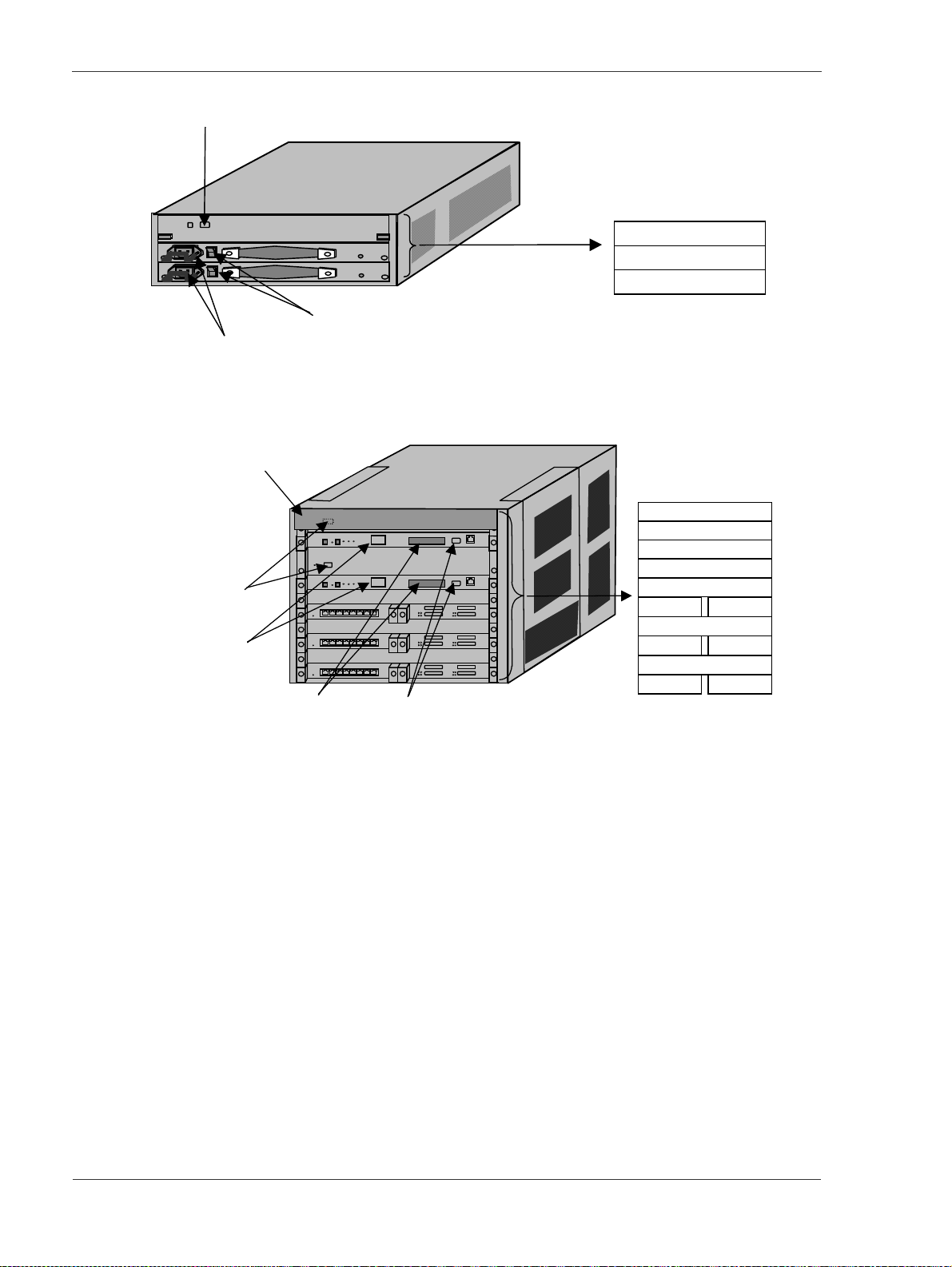
GR2000 Installation Guide
RS-232C port (for AUX)
Figure 2-4 Rear View of GR2000-4S (AC Input)
RS-232C port
(for AUX)
None in case of
RMB-CPU
LED (status
indicator)
Memory card slot
Power switch
Power cord receptacle
Acrylic Cover
88
88
RS-232C port (for console)
Two (CONSOLE & AUX) in case
of RMB-10
RM-CPU
POW1
POW0
RM-CPU1
RM-IO1
RM-CPU0
RM-IO0
RP0
NIF1 NIF0
RP1
NIF3 NIF2
RP2
NIF5 NIF4
Figure 2-5 Front View of GR2000-6H (AC Input)
2-4 GR2K-GA-1002
Rev 6.03
Page 61
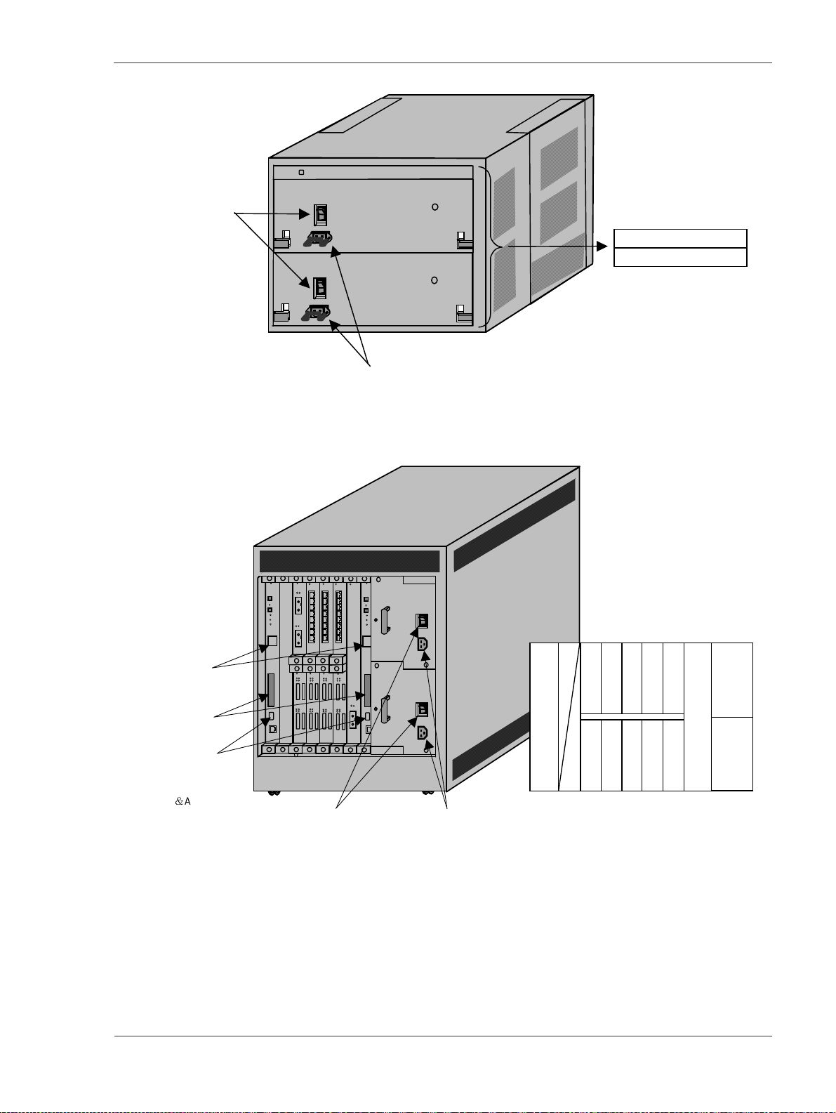
Power cord
receptacle
Power
switch
Power cord receptacle
Figure 2-6 Rear View of GR2000-6H (AC Input)
Product O verview
POW1
POW0
88 88
LED (status
indicator)
Memory
cardslot
RS-232C
connector
(for console)
Two (CONSOLE
AUX) in case
of RMB-10
3
0
Powerbreaker(100V)or switch(200V)
Two (CONSOLE & AUX) in case of RMB-10
Powercord receptacle
Figure 2-7 Fro nt View of GR2000-10H with AC Input
RM-
IO0
Placement of RM-IOand NIF
boards, and power supply units:
NIF
NIF
NIF
1
NIF
0
NIF
3
NIF
2
5
7
NIF4NIF
6
NIF
NIF
RM-
IO1
INPUT1
(AC)
INPUT0
(AC)
9
8
PS
PS
GR2K-GA-1002 2-5
Rev 6.03
Page 62

GR2000 Installation Guide
FAN3
FAN1
RS-232C
connector
(for AUX)
None in
caseof
RMB-CPU
FAN2
FAN0
Placementof RM-CPUand RP
boards,and power supply units:
DC-DC
DC-DC
3
RM-
1
RP4RP3RP
CPU
1
DC-DC
DC-DC
0
2
Placement of fans in fan tray (top view):
(front)
Fan 2
(power)
Fan 1
(power)
(rear)
FAN3
(front)
Fan 4
(main)
Fan 3
(main)
(rear)
FAN1
(power)
(power)
Upper fan tray
RP
RP
2
0
1
(front)
Fan 2
Fan 1
(rear)
FAN2
Lower fan tray
RM-
CPU
0
(front)
Fan 4
(main)
Fan 3
(main)
(rear)
FAN0
Figure 2-8 Rear View of GR2000-10H with AC Input
88 88
LED (status
indicator)
Memory
card slot
RS-232C
connector
(for console)
Two (CONSOLE
&AUX)incase
of RMB-10
3
0
Terminalblock
Powerbreaker
RM-
IO0
Placement of RM-IO and NIF
boards, and power supply units:
NIF
NIF
NIF
NIF
NIF
1
3
NIF
0
2
5
NIF4NIF
NIF
RM-
7
NIF
6
INPUT1
9
IO1
(DC)
INPUT0
8
(DC)
PS
PS
Figure 2-9 Fro nt View of GR2000-10H with DC Input
2-6 GR2K-GA-1002
Rev 6.03
Page 63

FAN3
FAN1
RS-232C
connector
(for AUX)
None in
caseof
RMB-CPU
FAN2
FAN0
Placementof RM-CPUand RP
boards,and power supply units:
DC-DC
DC-DC
3
DC-DC
2
RM-
CPU
1
RP4RP3RP
(front)
Fan 4
(main)
Fan 3
(main)
(rear)
FAN1
(power)
(power)
1
DC-DC
0
Placement of fans in fan tray (top view):
(front)
Fan 2
(power)
Fan 1
(power)
(rear)
FAN3
Upper fan tray
Product O verview
RP
RP
2
(front)
Fan 2
Fan 1
(rear)
0
1
(front)
Fan 4
(main)
Fan 3
(main)
(rear)
FAN2
Lower fan tray
FAN0
RM-
CPU
0
Figure 2-10 Rear View of GR2000-10 H with DC Input
GR2K-GA-1002 2-7
Rev 6.03
Page 64

GR2000 Installation Guide
LED (status
indicator)
Memory
cardslot
RS-232C
connector
(for console)
Two
(CONSOLE &
AUX) in case
of RMB-10
Terminal
block
88 88
Power breaker
NIF
NIF
NIF
1
NIF
0
NIF
NIF
5
7
3
NIF4NIF
6
2
PS INPUT0 (AC)
Figure 2-11 F ront View of GR2000-20H with AC Input
NIF
NIF
Placement of RM-IO, CSW, and NIF
boards, and power supply units:
NIF
NIF
15
17
NIF14NIF
16
NIF
19
NIF
18
NIF
CSW
RM-
9
0
IO0
CSW1RM-
IO1
8
NIF
11
13
NIF
NIF
10
12
PS INPUT1 (AC)
2-8 GR2K-GA-1002
Rev 6.03
Page 65

FAN3
FAN1
RS-232C
connector
(for AUX)
None in
case of
RMB-CPU
RP9RP8RP
7
DC-DC
5
RP
6
DC-DC
Product O verview
Placement of RM-CPUand RP
boards, and power supply units:
RP
4
5
RM-
CPU
1
DC-DC
RM-
CPU
3
RP4RP3RP
0
DC-DC
2
DC-DC
RP
RP
2
1
1
DC-DC
0
0
FAN2
FAN0
Figure 2-12 Rear View of GR2000-20 H with AC Input
Placement of fans in fan tray (top view):
(front)
Fan 2
(power)
Fan 1
(power)
(rear)
FAN3
Upper fan tray
(front)
Fan 4
(main)
Fan 3
(main)
(rear)
FAN1
(front)
Fan 2
(power)
Fan 1
(power)
(rear)
FAN2
Lower fan tray
(front)
Fan 4
(main)
Fan 3
(main)
(rear)
FAN0
GR2K-GA-1002 2-9
Rev 6.03
Page 66

GR2000 Installation Guide
T
LED (status
indicator)
Memory
card slot
RS-232C
connector
(for console)
wo
(CONSOLE &
AUX) in case
of RMB-10
Terminal
block
88 88
Power breaker
NIF
NIF
NIF
1
NIF
0
NIF
3
NIF4NIF
2
PS INPUT0 (DC)
Figure 2-13 Front View of GR2000-20H with DC Input
Placement of RM-IO, CSW, andNIF
boards, and power supply units:
NIF
NIF
CSW
RM-
5
7
9
0
NIF
6
8
IO0
CSW1RM-
IO1
PS INPUT1 (DC)
NIF
11
NIF
10
NIF
13
NIF
12
NIF
NIF
15
17
NIF14NIF
16
NIF
19
NIF
18
2-10 GR2K-GA-1002
Rev 6.03
Page 67
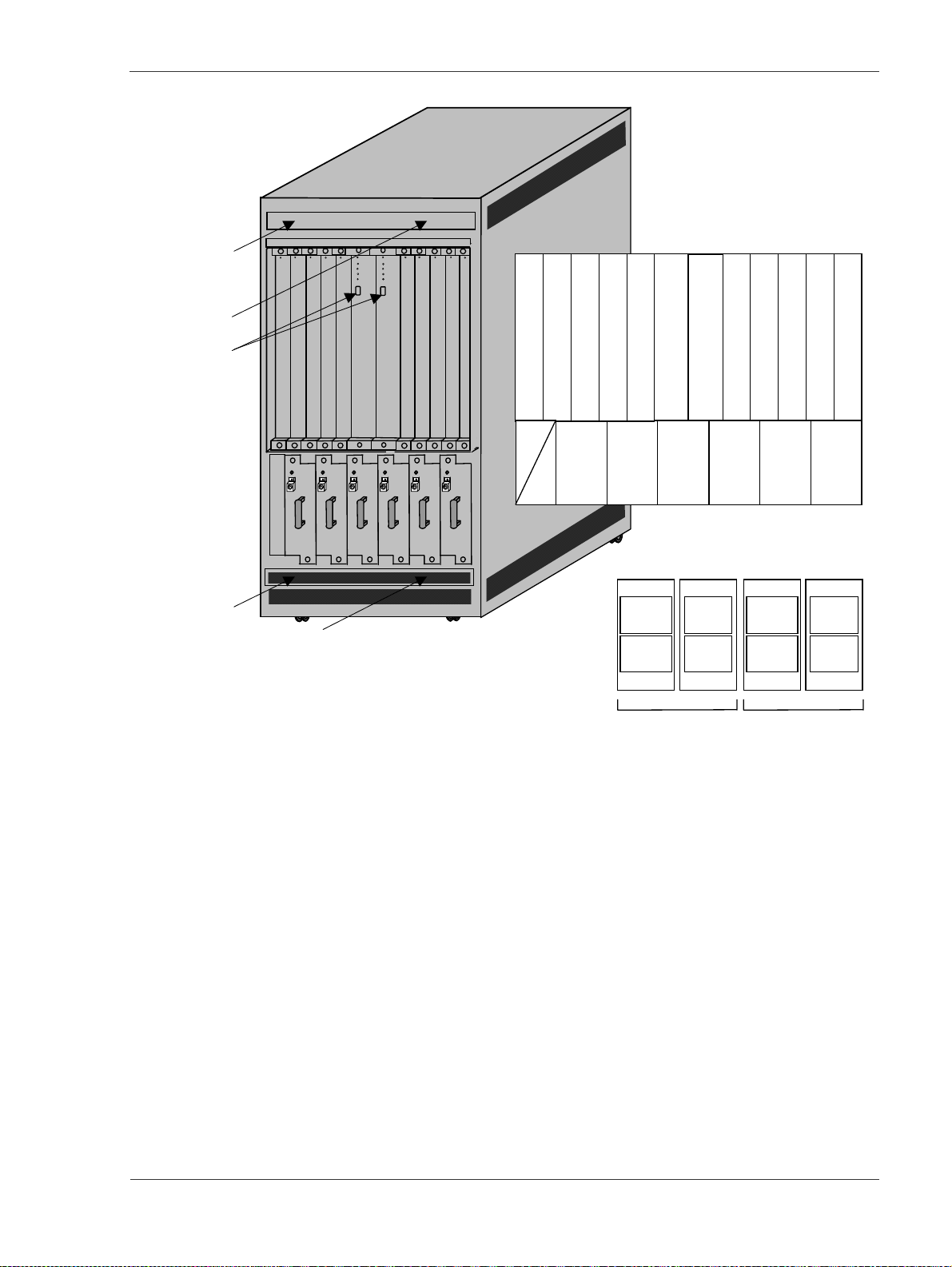
FAN3
FAN1
RS-232C
connector
(for AUX)
None in
case of
RMB-CPU
RP9RP8RP
7
DC-DC
5
RP
6
DC-DC
Product O verview
Placement of RM-CPUand RP
boards, and power supply units:
RP
4
5
RM-
CPU
1
DC-DC
3
RMCPU
0
DC-DC
RP4RP3RP
DC-DC
2
RP
RP
2
1
1
DC-DC
0
0
FAN2
FAN0
Figure 2-14 Rear View of GR2000-20 H with DC Input
Placement of fans in fan tray (top view):
(front)
Fan 2
(power)
Fan 1
(power)
(rear)
FAN3
Upper fan tray
(front)
Fan 4
(main)
Fan 3
(main)
(rear)
FAN1
(front)
Fan 2
(power)
Fan 1
(power)
(rear)
FAN2
Lower fan tray
(front)
Fan 4
(main)
Fan 3
(main)
(rear)
FAN0
GR2K-GA-1002 2-11
Rev 6.03
Page 68

GR2000 Installation Guide
Acrylic Cover
Memory card slot
LED (status
indicator)
88
3
Figure 2-15 Front View o f GR2000-4 (AC Input)
NIF3
NIF1
RM-IO
RP
NIF2
NIF0
Power switch
Power cord
receptacle
Power switch
Power cord
receptacle
Figure 2-16 Rear View of GR2000-4 (AC Input)
RM-CPU
POW1 POW0
2-12 GR2K-GA-1002
Rev 6.03
Page 69

Fan
c
LED (status
indicator)
Memory
card slot
RS-232Cconnector
Product O verview
88
RM-IO
Power switch
Power
receptacle
ord
AC power cord clamp
Placement of RM-IO and NIF
boards, and power supply units:
NIF
NIF
NIF
NIF
1
NIF
3
NIF
0
2
0
5
NIF4NIF
NIF
7
NIF
6
9
8
RM-IO
1
POW 1
POW 0
Figure 2-17 Front View of GR2000-10 with AC Input
Figure 2-18 Rear View o f GR2000-10 with AC In pu t
RM-
CPU
1
Placement of RM-CPUand
RP boards:
RP4RP3RP
2
RP
1
RP
0
RM-
CPU
0
GR2K-GA-1002 2-13
Rev 6.03
Page 70

GR2000 Installation Guide
L
P
M
Fan
ED (status
indicator)
emory
card slot
RM-IO
0
Placement of RM-IOand NIF
boards, and power supply units:
NIF
NIF
NIF
1
NIF
0
NIF
3
NIF
2
5
7
NIF4NIF
6
NIF
9
NIF
8
RM-IO
1
POW 1
POW 0
RS-232Cconnector
RS-232Cconnector
Breaker
ower cord receptacle
Figure 2-19 Front View of GR2000-10 with DC Input
Terminal block for
receivingDC input
power (M5 x 3 x2,
covered)
RM-
CPU
1
Placement of RM-CPU and RP
boards:
RP4RP3RP
2
RP
1
RP
0
RM-
CPU
0
Figure 2-20 Rear View o f GR2000-10 with DC In pu t
2-14 GR2K-GA-1002
Rev 6.03
Page 71

Product O verview
N
N
CSW board (covered):
CSW-1S
CSW-1M
CSW-0S
CSW-0M
88
NIF
RM-
IO0
NIF
LED (status
indicator)
Memory
card slot
RS-232C
connector
Power Switch
Power cord
receptacle
88
Figure 2-21 Front View of GR2000-20 with AC Input
Placement of RM-IO and NIF
boards:
NIF
NIF
NIF
NIF
NIF
IF
1
3
5
NIF
NIF
0
NIF
2
4
NIF
7
9
11
NIF12NIF
IF
NIF
6
8
10
13
15
14
NIF
17
NIF
16
NIF
19
NIF
18
RM-
IO1
GR2K-GA-1002 2-15
Rev 6.03
Page 72
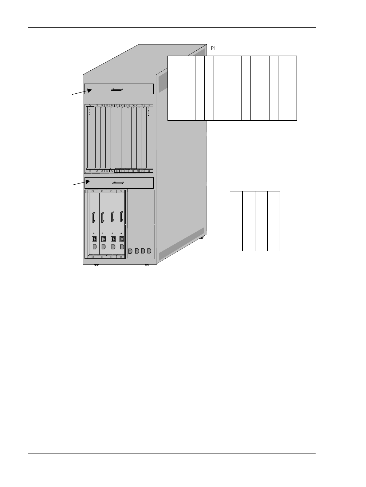
GR2000 Installation Guide
Placement of RM-CPUand RP boards:
Fan
Fan
RP9RP8RP7RP
RM-
CPU
RP4RP3RP2RP
5RP6
RP
1
1
RM-
0
CPU
0
Placement of power supply units:
Power
Power
Power
Unit
1-1
Unit
1-0
Unit
0-1
Power
Unit
0-0
Figure 2-22 Rear View o f GR2000-20 with AC In pu t
2-16 GR2K-GA-1002
Rev 6.03
Page 73

Product O verview
N
N
CSW board (covered):
CSW-1S
CSW-1M
CSW-0S
CSW-0M
88
NIF
RM-
IO0
NIF
LED (status
indicator)
Memory
card slot
RS-232C
connector
88
Figure 2-23 Front View of GR2000-20 with DC Input
Placement of RM-IO and NIF
boards:
NIF
NIF
NIF
NIF
NIF
IF
1
3
5
NIF
NIF
0
NIF
2
4
NIF
7
9
11
NIF12NIF
IF
NIF
6
8
10
13
15
14
NIF
17
NIF
16
NIF
19
NIF
18
RM-
IO1
GR2K-GA-1002 2-17
Rev 6.03
Page 74

GR2000 Installation Guide
F
Placement of RM-CPU and RP boards:
Fan
an
RP9RP8RP7RP
RMCPU
1
RP
RP4RP3RP2RP
5
6
0RP1
Placement of power supply units:
Power
Power
Power
Unit
1-1
Unit
1-0
Unit
0-1
Power
Unit
0-0
RM-
CPU
0
Figure 2-24 Rear View o f GR2000-20 with DC In pu t
2-18 GR2K-GA-1002
Rev 6.03
Page 75

Product O verview
Guide rail attached Guide rail detached
Figure 2-25 Half-Sized and Full-Sized NIF Modules
GR2K-GA-1002 2-19
Rev 6.03
Page 76

GR2000 Installation Guide
2.3 Device Configuration
All of the GR2000 models have the same architecture and share common
components, including: Routing Manager (RM), Routing Processor (RP), Network
Interface Unit (NIF), power supply subsystem (PS), and cabinet. In addition, the
mid-range and high-end models (GR2000-6H, GR2000-10H, GR2000-20H)
implement a highspeed RM–RP connection by means of the Crossbar Switch (CSW).
The device components are collectively called the Basic Control Unit (BCU). A brief
description of each component is given below:
Routing Manager: The RM manages the entire router and processes routing
protocols. The routing processes include creation and update of routing tables
and forwarding routing tables to the Routing Processor (RP). In the GR2000-2S,
the Routing Manager/Processor (RMP) integrates the functions of th e RM and RP.
In all other models, the RM is ma de up of two separate units: RM-CPU and
RM-IO.
Routing Processor (RP): The RP provides wire speed packet relaying in
accordance with the routing table information supplied by the RM. It also
performs ARP/ICMP processing, control of Network Interface Units, processing of
network interface p rotocols (e.g., PPP, frame relay, and ATM), statistic functions,
and error handling. In the GR2000-6H, GR2000-10H and GR2000-20H, an
additional RP provides load balancing and faster processing speeds.
Network Interface Unit (NIF): The NIF provides Layer 1 and Layer 2 support for
various interfaces. Since the NIF is separate from the RP and provides for specific
interfaces, a high degree o f flexibility is achieved, meeting a wide range of user
needs.
Power Supply Unit (POW): The POW uses external power to generate a stable
direct current for the internal units of the router. In the GR2000-4S, GR2000-6H,
GR2000-10H and GR2000-20H, an additional POW provides a duplexed power
supply configuration that improves the systems a vailability.
Crossbar Switch (CSW): The CSW provides highspeed packet transfer between
the RM and RP for the following models of GR2000-6H, GR2000-10H,
GR2000-20H, GR2000-4, GR2000-10, and GR2000-20.
Basic Control Unit (BCU): In the GR2000-2S, the BCU consists of an RMP (a
duplexed BCU configuration is not available). In the GR2000-4S, the BCU
consists of the RM (a duplexed BCU configuration is not available). In the
GR2000-6H, GR2000-10H and GR2000-20H, the BCU consists of the RM and
the CSW; a duplexed BCU configuration option is available and is independent of
the duplexed power supply configuration. The BCU also contains the default
memory on th e RM, flash memory cards, and software.
Ease of operation and maintenance is achieved by the hot-swapping capability of
components. On GR2000-2S, the NIF is hot-swappable when more than one NIF is
installed; on GR2000-4S and GR2000-4, the NIF and the POW are hot-swappable
when more than one NIF is installed, o r when the power supply is duplexed. On the
restofthemodels,theBCU,RP,NIF,andPOWarehot-swappablewhentheBCUis
duplexed, more than one RP is installed, more than one NIF is installed, or the
power supply is duplexed.
Figure 2-26, Figure 2-27, and Figure 2-28 show the block diagrams of the GR2000
models. A brief expla nation of each model follows.
2-20 GR2K-GA-1002
Rev 6.03
Page 77

N
BCU
N
N
B
N
R
Product O verview
RMP(RM+ RP)
NIF
ATM
IF
WAN
Figure 2-26 Block Diagram of GR200 0-2S
BCU
RM
NIF
NIF
RP
Bus
IF
Built-in
10M/100M
Ethernet
(4 ports)
LAN
us
POW
IF
POW
POW
Option for
redundant
configuration
LAN
LAN
WAN
ATM
Figure 2-27 Block Diagram of GR200 0-4S
BCU
RM
NIF
LAN
RP
NIF
LAN
BCU
RM
CSW
CSW
IF
WAN
POW
POW
P
NIF
ATM
Figure 2-28 Block Diagram of GR2000-6H, GR2000-10H and GR2000-2 0H
Option for
redundant
configuration
GR2K-GA-1002 2-21
Rev 6.03
Page 78

GR2000 Installation Guide
GR2000-2S
The GR2000-2S incorporates one BCU with one 10M/100M Ethernet (4 ports),
and one POW. The BCU consists of one RMP (equivalent of RM and RP)
physically packaged in one RM-CPU module and one RMP module with one 10M/
100M Ethernet (4 ports). Up to two NIFs can be installed on the GR2000-2S.
Power supply redundancy is not available on this model.
The front view is shown in Fig. 2-10, the front appearance view of GR2000-2S,
and the rear view in Fig. 2-11, the rear appearance view of GR2000-2S.
Memory
card slot
RS-232C port
(for console)
LED (status
indicator)
88
Integrated Ethernet port (10M/100M) x 4
Figure 2-29 Front View of GR2000-2S
Power switch
Power cord receptacle
Mounting position of
RMP and NIF board.
NIF1 NIF0
FAN1
FAN2
FAN4
MountingpositionofRM-CPU and power supply
RM-CPU with POW
unit (device integrated type)
FAN3
RMP
Figure 2-30 Rear View of GR2000-2S
GR2000-4S
This model incorporates one BCU, one RP, and one POW; the BCU consists of one
RM physically packaged in one RM-CPU module and one RM-IO module. Up to
four NIFs can be installed on this model. Power supply redundancy is made
available by mounting one optional POW in the POW1 slot; otherwise, only the
base POW is mounted in the POW0 slot. BCU redundancy, available on higher
models,isnotavailableonthismodel.
ThefrontviewisshowninFigure2-31,thefrontappearanceviewofGR2000-4S,
and the rear view in Figure 2-32, the rear appearance view of GR200-4S.
2-22 GR2K-GA-1002
Rev 6.03
Page 79

Product O verview
R
Memory card slot
LED (status
indicator)
88
3
Figure 2-31 Front View of GR2000-4S
RS-232C port (for AUX)
RS-232C por t (for console)
Mounting position of
RMP-IO, RP and NIF
board.
Mounting position of
RM-CPU board and
power supply unit
(device integrated type)
NIF3
NIF1
RM-CPU
POW1
POW0
M-IO
RP
NIF2
NIF0
Power switch
Power cord receptacle
Figure 2-32 Rear View of GR2000-4S
GR2000-6H
This model incorporates one BCU, one RP, and one POW; the BCU consists of one
RM and one CSW, and is physically packag ed in one RM-CPU module and one
RM-IO module. One BCU for redundancy, up to two additional RPs, and one POW
for redundancy can be installed as options, independently of one another. Since
one RP can handle up to two NIFs, a total of six NIFs can be installed on this
model. The BCU redundancy is made available by mounting the optional
RM-CPU and RM-IO modules in the RM-CPU1 and RM-IO1 slots; otherwise, only
thebaseRM-CPUandRM-IOmodulesaremountedintheRM-CPU0andRM-IO0
slots. Similarly, the power supply r edundancy is made available by mounting the
optional POW in the POW1 slot; otherwise, only the base POW is mounted in the
POW0 slot.
The front view is shown in Figure 2-33, the front appearance view of GR2000-6H,
and the rear view in Figure 2-34, the rear appearance view of GR2000-6H.
GR2K-GA-1002 2-23
Rev 6.03
Page 80

GR2000 Installation Guide
RS-232C port
(forAU X)
LED (status
indicator)
Mem ory card slot
Figure 2-33 Front View of GR2000-6H
Acrylic Cover
88
88
RS-232 C po rt (for console)
Power cord
receptacle
RM-CPU1
RM-IO 1
RM-CPU0
RM-IO 0
RP0
NIF1 NIF0
RP1
NIF3 NIF2
RP2
NIF5 NIF4
The RP.NIF nu mbe r starts f ro m 0.1
on the upper tier, being different
from 4S.
Mounting position of
Power
switch
power supply unit
POW1
POW0
Power cord receptacle
Figure 2-34 Rear View of GR2000-6H
GR2000-10H
This model incorporates one BCU, one RP, and two POWs; the BCU consists of
one RM and one CSW, and is physically packaged in one RM-CPU module and
one RM-IO module. One BCU for redundancy, up to four additional RPs, and two
POWs for redundancy can be installed as options, independently of one another.
SinceoneRPcanhandleuptotwoNIFs,atotaloftenNIFscanbeinstalledon
this model. The BCU redundancy is made available by mounting the optional
RM-CPU and RM-IO modules in the RM-CPU1 and RM-IO1 slots; otherwise, only
thebaseRM-CPUandRM-IOmodulesaremountedintheRM-CPU0andRM-IO0
slots.
The front view when PS is mounted with an A C input unit is shown in Figure
2-35, the front appearance view of G R2000-10H (AC input), and the rear view in
Figure 2-36, the rear appearance view of GR200-10H(AC input).
2-24 GR2K-GA-1002
Rev 6.03
Page 81

For the device configuration when PS is mounted with a DC input unit, and the
PS m ounting position, please refer to the "Hardware operation manual".
Slot for the RM-10 NIF board
AC input unit mounting
position.
LED (status
indicator)
88 88
RM-
IO0
NIF
NIF
1
3
NIF
5
Product O verview
NIF
NIF
RM-
7
9
IO1
PS
INPUT1
(AC)
Memory
cardslot
RS-232C
connector
(for console)
3
0
Powerbreaker (100V) or switch (200V)
Powe rcord receptacle
Figure 2-35 Front View of GR2000-10H with AC Input
FAN1
FAN3
DC-DC
Power
supply unit
DC-DC
3
DC-DC
2
NIF4NIF
NIF
NIF
0
Mounting position of RM-CPU, RP
board powersupply unit:
DC-DC
RM-
1
CPU
1
DC-DC
0
6
2
RP4RP3RP
2
NIF
8
RP
1
RP
0
PS
INPUT0
(AC)
RM-
CPU
0
Placement of fans in fan tray (top view):
FAN2
FAN0
RS-232C
connector
(for AUX )
(front)
Fan 2
(power)
Fan 1
(power)
(rear)
FAN3
Upper fan tray
(front)
Fan 4
(main)
Fan 3
(main)
(rear)
FAN1
(front)
Fan 2
(power)
Fan 1
(power)
(rear)
FAN2
Lower fan tray
(front)
Fan 4
(main)
Fan 3
(main)
(rear)
FAN0
Figure 2-36 Rear View of GR2000-10 H with AC Input
GR2K-GA-1002 2-25
Rev 6.03
Page 82

GR2000 Installation Guide
GR2000-20H
This model incorporates one BCU, one RP, and three POWs; the BCU consists of
one RM physically packaged in one RM-CPU m odule and one RM-IO module, and
one CSW physically packaged in one master CSW module (CSW-M) and one sub
CSW module (CSW-S). One BCU for redundancy, up to nine additional RPs, and
three POWs for redundancy can be installed as options, independently of one
another. Since one RP can handle up to two NIFs, a total of twenty NIFs can be
installed on this model. The BCU redundancy is made available by mounting the
optionalRM-CPU,RM-IO,CSW-M,andCSW-SmodulesintheRM-CPU1,
RM-IO1, CSW-1M, and CSW-1S slots; otherwise, only the base RM-CPU, RM-IO,
CSW-M, and CSW-S modules are m ounted in the RM-CPU0, RM-IO0, CSW-0M,
and CSW-0S slots.
The front view is shown in Figure 2-37, the front appearance view of
GR2000-20H (AC input), and the rear view in Figure 2-38, the rear appearance
view of GR200-20H(AC input).
For the device configuration when PS is mounted with a DC input unit, and the
PS m ounting position, please refer to the "Hardware operation manual".
LED (status
indicator)
Memory
cardslot
RS-232C
connector
(for console)
Terminal
block
88 88
Power breaker
NIF
NIF
NIF
1
NIF
0
NIF
NIF
5
3
NIF4NIF
2
PS INPUT0 (AC)
Figure 2-37 Front View of GR2000-20H with AC Input
Mountingposition of R M-IO,
CSW, NIF board
NIF
CSW
RM-
7
9
0
NIF
6
8
IO0
CSW1RM-
IO1
PS INPUT1 (AC)
NIF
11
NIF
10
NIF
13
NIF
12
NIF
NIF
15
17
NIF14NIF
16
NIF
19
NIF
18
2-26 GR2K-GA-1002
Rev 6.03
Page 83

RS-232C
connector
(for AUX)
DC-DC
power
supply
unit x 6
FAN3
FAN1
RP9RP8RP
7
RP
6
Product O verview
Mounting position of RM-CPU and
RP board:
RP
RM-
CPU
5
1
RM-
CPU
0
RP4RP3RP
2
RP
1
RP
0
FAN2
FAN0
Mounting position of DC-DC power supply unit:
POW
POW
5
POW
4
POW
3
POW
2
POW
1
0
Figure 2-38 Rear View of GR2000-20 H with AC Input
Placement of fans in fan tray (top view):
(front)
Fan 2
(power)
Fan 1
(power)
(rear)
FAN3
Upper fan t ray
(front)
Fan 4
(main)
Fan 3
(main)
(rear)
FAN1
(front)
Fan 2
(power)
Fan 1
(power)
(rear)
FAN2
Lower fan tray
(front)
Fan 4
(main)
Fan 3
(main)
(rear)
FAN0
GR2K-GA-1002 2-27
Rev 6.03
Page 84

GR2000 Installation Guide
2.4 Device Components
Table 2-1 and Table 2-3 show the maximum number of device components described
in this section, depending on the target GR2000 model.
Table 2-1 Maximum Number of Device Components on Enhanced Models
Device Component GR2000-2S GR2000-4S GR2000-6H GR2000-10H GR2000-20H
Power Supply Unit (POW) 1 2 2 1 1
Additional POW (POWA) 0 0** 0** 1 1
Basic Control Unit (BCU) 1 1 2 2 2
(a) Main memory
(MS64, MS128, MS256)***
(b) Memory Card (MC64) 2 2 2/BCU 2/BCU 2/BCU
Pouting Processor (RP) 0* 1 3 5 10
(a) Main memory (MS64) RP-A1 1 1/RP 1/RP 1/RP 1/RP
(b) Main memory (MS128) RP-A1 - - - - -
Network Interface Unit (NIF) 2 4 6 10 20
Notes:
* One RP- A1equivalent is incorporated in BCU on GR2000-25.
** Power supply redundancy is implemented by installing two POWs on GR2000-4S, 6H.
*** MS256 is dedicated for BCU-H850H, BCU-M850H, and BCU-L850H.
BCU other than
below
BCU-H850H
BCU-M850H
BCU-L850H
RP-C - - 0 0 0
RP-D - 1/RP 1/RP 1/RP 1/RP
RP-C6,RP-D6 - - 1/RP 1/RP 1/RP
RP-C - - 0 0 0
RP-D - 0 0 0 0
RP-C6,RP-D6 - - 1/RP 1/RP 1/RP
2 2 2/BCU 2/BCU 2/BCU
- - 4/BCU 4/BCU 4/BCU
2-28 GR2K-GA-1002
Rev 6.03
Page 85

2.4.1 Cabinet (Network ProcessorUnit Chassis)
EachmodeloftheGR2000familyhasitsowncabinetthatincludesoneormorefans
for cooling. See Figures 2-1 thru 2-24 in 2.2 for their external images.
Table 2-2 Each cabinet and maximum number of modul es that can be moun ted Devi ce
Cabinet
Product O verview
Device
cabinet
GR2000-2S BCU (R M-CPU and RMP) 1 (Built in. )
GR2000-4S BCU (RM) 1
GR2000-6H BCU(RM and CSW) 2 Possible of duplication.
GR2000-10H BCU (R M and CSW) 2 Possible of duplication.
GR2000-20H BCU (RM) 2 Possible of duplication.
Constituting element
Corresponding to RP-A1. 1 (Built in. )
NIF 2
PS 1 (Built in. )
RP 1
NIF 4
PS 2 Possible of duplication.
RP 3
NIF 6
PS 2 Possible of duplication.
RP 5
NIF 10
PS 4
CSW 2 Possible of duplication.
RP 10
NIF 20
PS 6 Possible of duplication.
Maximum number of
modules that can be
mounted
Remarks
2.4.2 Basic Control Unit (BCU)
The components of the BCU vary depending on the GR2000 models as shown below.
Table 2-3 Abbreviation for BCU model names and configuration of each device
Device cabinet
GR2000-2S Built in cabinet • RM-CPU(2S) board
GR2000-4S BDU-S300S • RM-CPU (4S) board
GR2000-6H BCU-H300H • RM-CPU (HH) board
GR2K-GA-1002 2-29
Rev 6.03
Abbreviation for
BCU model name
• RMP boards (to handle RM-IO, RP-A1, 10BASE-T/
100BASE/TX (4 boards) are built in).
• RM-IO (4S) board
• RM-IO (H) board (Built-in 4x4 cross bar switch)
BCU-H850H • RMB-CPU (HH) board
• RMB-IO (H) board ( Built in 4x4 cross bar switch)
Configuration
Page 86

GR2000 Installation Guide
Table 2-3 Abbreviation for BCU model names and configuration of each device
Device cabinet
GR2000-10H BCU-M300H • RM-CPU (MH) board
GR2000-20H BCU-L300H • RM-CPU (LH) board
2.4.2.1 RM-CPU
Each RM-CPU contains one K6-2 [300 MHz] processor a nd two main memory slots.
Each memory slot accepts a 64 MB memory module (MS64) and a 128 MB memory
module (MS128), thus being able to configure up to 256 MB of memory. In addition,
each RM-CPU of GR2000-4S, GR2000-6H, GR2000-10H, and GR2000-20H includes
one RS-232C AUX port.
2.4.2.2 RM-IO
Each RM-IO has one RS232 console port, two memory card (MC) slots, one
10BASE-T port, and a packet-forwarding ASIC.
Abbreviation for
BCU model name
• RM-IO (H) board (Built in 6x6 cross bar switch)
BCU-M850H • RMB-CPU (MH) board
• RMB-IO (H) board ( Built in 6x6 cross bar switch)
• RM-IO (H) board
BCU-L850H • RMB-CPU (LH) board
• RMB-IO (H) board
Configuration
2.4.2.3 RMB-CPU
Each RMB-CPU has a common Pentium III (850 MHz) and four mai n storage (MS)
slots. Since the main storage of 256 bytes (MS256) can be mounted, a memory of 1G
bytesasmaximumcanbemounted.
Being different from RM-IO, BCU-S850S, BCU-H850H, BCU-M850H, and
BCU-L850H have the RS -232C AUX board in RMB-IO.
2.4.2.4 RMB-IO
RMB-IO has two RS232C console boards, two memory card (MC) mechanism slots,
one board of 10BASE-T/100BASE-TX, and a packet forwarding engine (Packet
Forwarding ASIC).
Duplication o f BCU is possible only in GR2000-6H, GR2000-10H and GR2000-20H
by m ounting two sets of BCU.
2-30 GR2K-GA-1002
Rev 6.03
Page 87

2.4.2.5 Crossbar Switch (CSW)
The CSW provides highspeed packet transfer between the RM and the RP on the
models of GR2000-6H, GR2000-10H and GR2000-20H.
On GR2000-6H, the CSW is included in the RM-CPU bo ard. Its 3-by-3 crossbar
switch performs highspeed packet transfer between RM and up to 3 RPs.
On GR2000-10H, the CSW is included in the RM-CPU board. Its 6-by-6 crossbar
switch performs highspeed packet transfer between RM and up to 5 RPs.
On GR2000-20H, the CSW is implemented as two separate boards (CSWM and
CSWS), one acting as backup. Its 11-by-11 crossbar switch performs highspeed
packet transfer between RM and up to 10 RPs.
2.4.3 Routing Processor Module(RP)
TheRPusestheroutingtablefromtheRPtoperformpacketrelay,ARPandICMP
processing, NIF control, protocol handling on the data link layers (for PPP, frame
relay, and ATM), statistics, and fault handling, etc. The GR2000-6H, GR2000-10H,
and GR2000-20H use the load distribution method to allow the use of more than one
RP simultaneously.
Product O verview
The RP contains a packet forwarding engine (implemented by an ASIC), a routing/
QoS and filtering table lookup engine (implemented by an ASIC) that performs
hardware-based routing table lookup, and a filtering table and QoS table lookup.
This hardware-based method allows faster IP forwarding and QoS services.
TheRPusessoftwarefornetworklayerhandling(forPPP,framerelay,ATM,etc.),
IPX, packet relay on bridges, statistics, and fault handling.
The RP has two types of RPs: RP-A1 and RP-D for low to high-speed line control and
RP-C for ultrahigh-speed line control. Table 2-4 shows the specifications for each
RP.
The GR2000-2S contains an RP-A1 equivalent.
GR2K-GA-1002 2-31
Rev 6.03
Page 88

GR2000 Installation Guide
Table 2-4 RP Specifications
RP name Specification Note
RP-A1 Backup, QoS/Diff-serv, and multicasting
Packet transfer rate: Approx. 1M packets/s
MS = 32MB (standard) - 96MB (max)
RP-DV RP- DV is a routing processor to which the label stack H/W transfer function has
been enhanced.
Packet transfer rate: Approx. 4M packets/s
MS = 128MB (fixed)
• The packet transfer engine is commonly used for transmission and reception.
• Routing retrieval engines are mounted exclusively for transmissionand
reception, respectively.
• The mounted processor is MIPS RM7000 |250Mhz|.
RP-D In addition to the RP-A1’s features, MPLS and Tag VLAN coupling
Packet transfer rate: Approx. 1M packets/s
MS = 64MB (standard) - 128MB (max)
• Packettransfer engine is used commonly for transmission and reception.
• Routing retrieval engine is used commonly for transmission and reception.
• The mounted processor is MIPS RM7000 |250Mhz|.
RP-C RP-C is a routing processor to accommodate high-speed lines including OC-48c,
which has a packet processing performance about four times greater than that of
RPA1.
GR2000 IPv6 compatible
Has RP-C function
IPv6, IPv4 dual stack
Packet transfer rate: 4.0Mpps (IPv4)
(Full duplex)2.6Mpps (IPv6)
MS = 128MB (standard) - 256MB (max)
• Packettransfer engines are mounted exclusively for transmission and reception,
respectively.
• Routing retrieval engines are mounted exclusively for transmissionand
reception, respectively.
• The mounted processor is MIPS RM7000 |250Mhz|.
GR2000-2S: Not
mountable
GR2000-4S,2S:
Not mountable
GR2000-10,20:
Mountable with
some limitations
(*1)
GR2000-2S: Not
mountable
GR2000-4S:
Mountable with
some feature
limitations(*2)
GR2000-4S, -2S:
Not mountable
GR2000-10, -20:
Separate price
quote
2-32 GR2K-GA-1002
Rev 6.03
Page 89

Product O verview
Table 2-4 RP Specifications
RP name Specification Note
RP-D6 GR2000 IPv6 compatible
Has RP-D function
IPv6, IPv4 dual stack
Packet transfer rate: 1.0Mpps (IPv4)
(Full duplex)0.8Mpps (IPv6)
MS = 128MB (standard) - 256MB (max)
• Packettransfer engine is used commonly for transmission and reception.
• Routing retrieval engine is used commonly for transmission and reception.
• The mounted processor is MIPS RM7000 |250Mhz|.
RP-C6 RP-C6 is a routing processor to which the hardware routing function of IPv6 has
been enhanced on RP-C to accommodate high-speedlines such as OC-48c and the
gigabit Ethernet of multi-port versions. Its hardware configuration is as follows:
• The packet transfer engines are exclusivelymounted f or transmission and
reception.
• The routing retrieval engines are exclusively mounted for t ransmission and
reception.
• The mounted processor is MIPS RM7000 "250 MHz".
• A memory of 128 M bytes is mounted in a fixed way.
RP-CV RP-CV is a routing processor to which the hardware r outing function of IPv6 has
been enhanced on RP-C to accommodate high-speedlines such as OC-48c and the
gigabit Ethernet of multi-port versions. Its hardware configuration is as follows:
• The packet transfer engines are exclusivelymounted f or transmission and
reception.
• The routing retrieval engines are exclusively mounted for t ransmission and
reception.
• The mounted processor is MIPS RM7000 "250 MHz".
• A memory of 128 M bytes is mounted in a fixed way.
(*1) For the GR2000-10/20, there are some limitations on installation of RP-C boards and NIF modules supporting
them. For more information,see "adding enhanced features" in Section 7.1.1.
(*2) The MPLS or MPLS-based IP-VPN feature is not available for the GR2000-2S/4S.
GR2000-2S: Not
mountable
GR2K-GA-1002 2-33
Rev 6.03
Page 90

GR2000 Installation Guide
2.4.4 Network Interface Module (NIF)
The NIF provides Layer 1 and Layer 2 support for various WAN and LAN interfaces.
The NIF includes half-size and full-size boards. See Table 2-5 for a list of NIF
modules.
Table 2-5 List of NIF Modules
Type Module Name Interface Size
LAN NE100-8T 10BASE-T/100BASE-TX 8 ports half
NE100-8TA 10BASE-T/100BASE-TX 8 ports (VRRP and MPLS supported) half
NE100-8TB 10BASE-T/100BASE-TX8 ports(VRRP, MPLS, VLAN, band control
supported)
NE100-4F 100BASE-FX (long wavelength 1300 nm, normal, multimode fiber) 4
ports
NE100-4FS** 100BASE-FX (middle) (long wavelength 1300 nm, middle distance,
single-mode fiber) 4 ports
NE100-4FS4** 100BASE-FX(long) (long wavelength 1300 nm, long distance,
single-mode fiber) 4 ports
NE1G-1S 1000BASE-SX (short wavelength 850 nm) 1 port full
NE1G-1SA 1000BASE-SX (short wavelength 850 nm) 1 port (VRRP supported) full
NE1G-1SB 1000BASE-SX(short wavelength 850nm) 1
port(VRRP,MPLS,VLAN,band control supported)
NE1G-1L 1000BASE-LX (long wavelength 1300 nm) 1 port full
NE1G-1LA 1000BASE-LX (long wavelength 1300 nm) 1 port (VRRP supported) full
NE1G-1LB 1000BASE-LX(short wavelength 1300nm) 1
port(VRRP,MPLS,VLAN,band control supported)
NE1G-1LHA** 1000BASE-LH (long wavelength 1500 nm) 1 port full
NE1G-1LHA8** 1000BASE-LH8 (long wavelength 1500 nm) 1 port (80 km supported) full
NE1G-1LHBA** 1000BASE-LH(long wavelength 1500nm) 1port (100km ,
VRRP,MPLS,VLAN, band control supported)
NE1G-4C 1000BASE-SX, 1000BASE-LX, 1000BASE-LH
4ports (GBIC supported) (VRRP,MPLS,VLAN, band control supported)
WAN NWVX-4 V24(upto64k)/V35(upto6M)/X21(upto6M)synchronizationserial
4 ports
NWVX-8 V24(upto64k)/V35(upto2M)/X21(upto2M)synchronizationserial
8 ports
NWJB-8* Basic interface (64/128k) 8 ports (leased line/ISDN) half
NWMX1-4* High-speed digital (1.5M) 2 ports plus Basic interface (64/128k) 2 ports
(leased line/ISDN)
NWJ1-4U* High-speed digital (1.5M) 4 ports (leased line/ISDN) half
NWJ1-8U* High-speed digital (1.5M) 8 ports (leased line/ISDN) half
NWT1-4 High-speed digital ( 1.5M) 4 ports (North America) half
NWE1-4 High-speed digital (2M) 4 ports (Europe, Asia) half
NWE1-8 High-speed digital (2M) 8 ports ( MPLS supported) half
NWJ2-1U * High-speed digital (6M) 1 port half
NWT3-2U High-speed digital (non-multiplex 45M) 2 ports half
half
half
half
half
full
full
full
full
half
half
half
2-34 GR2K-GA-1002
Rev 6.03
Page 91

Product O verview
Table 2-5 List of NIF Modules
NWE3-2U High-speed digital (non-multiplex 35M) 2 ports half
NWE3-1C High-speed digital (mutiplex 34M) 1 port half
NWOC3C-2M SONET/SDH OC-3c/STM-1(150M) POS 2 ports (multimode f iber) half
NWOC3C-2MD SONET/SDH OC-3c/STM-1 (150M) POS 2 ports
(multimode fiber)(MPLS supported)
NWOC3C-8M SONET/SDH OC-3c/STM-1 (150M) POS 8 ports (multimode fiber) 2km full
NWOC3C-2S SONET/SDH OC-3c/STM-1(150M) POS 2 ports (single-mode fiber) half
NWOC3C-2SD SONET/SDH OC-3c/STM-1 (150M) POS 2 ports (single-mode fiber)
(MPLS supported)
NWOC3C-8S SONET/SDH OC-3c/STM-1 (150M) POS 8 ports (single-mode fiber)
15km
NWOC12-4M SONET/SDH OC-12c/STM-4 (600M) POS 4 ports (multimode fiber)
500m
NWOC12C-1S SONET/SDH OC-12c/STM-4(600M) POS 1 port (single-modefiber) full
NWOC12-1SD SONET/SDH OC-12c/STM-4 (600M) POS 1 port (single-mode f iber)
(MPLS supported)
NWOC12-4S SONET/SDH OC-12c/STM-4 (600M) POS 4 ports (single-mode fiber)
15km
NWOC48-1S SONET/SDH OC-48c/STM-16(2.4G)POS 1 port (single-mode fiber) 2km full
NWOC48-1S4 SONET/SDH OC-48c/STM-16(2.4G) POS 1 port (single-mode fiber)
40km
NWOC48-1S8 SONET/SDH OC-48c/STM-16 (2.4G)POS 1 port (single-mode fiber)
80km
NWOC48-1A SONET/SDH OC-48c/STM-16 (2.4G) POS 1 port (single-mode fiber)
2km (APS supported)
NWOC48-1A4 SONET/SDH OC-48c/STM-16 (2.4G) POS 1 port (single-mode fiber)
40km (APS supported)
NWOC48-1A8 SONET/SDH OC-48c/STM-16 (2.4G) POS 1 port (single-mode fiber)
80km (APS supported)
ATM NA25M-1* 25Mbps ATM 1 port half
NAOC3-1M SONET/SDH OC-3/STM-1(150M) ATM 1 port (multimode fiber) half
NAOC3-1S SONET/SDH OC-3/STM-1(150M) ATM 1 port (single-mode fiber) half
NAOC3-8M** SONET/SDH OC-3c/STM-1(150M) ATM 8 ports(multimode fiber) full
NAOC3-8S** SONET/SDH OC-3c/STM-1(150M) ATM 8 ports(single-mode fiber) full
NAOC12-2M** SONET/SDH OC-12c/STM-4 (600M) ATM 2 ports (mulimode fiber) full
NAOC12-2S** SONET/SDH OC-12c/STM-4 (600M) ATM 2 ports (sigle-mode fiber) full
* These interfaces ar e for use in Japan only.
** Product intended for the Japanese market handled only by Hitachi Japan.
half
half
full
full
full
full
full
full
full
full
full
GR2K-GA-1002 2-35
Rev 6.03
Page 92

GR2000 Installation Guide
2.4.5 Power Supply Unit (POW)
The POW receives externally-sourced input power a nd generates stable direct voltage
current (5V, 3.3V, 12V, and 24V) for the r outer. For input power, GR2000-2S and
GR2000-4S can receive 100 or 200 VAC (50/60 Hz); GR2000-6H and GR2000-10H
can receive 100 or 200 VAC (50/60 Hz), or –48 or –60VDCifDCinputpoweroption
is installed; GR2000-20H can receive 200 VAC (50/60 Hz), or –48 or –60 VDC if DC
input power option is installed.
In any power supply that is duplicable, the external power supply cables are
independent, thus duplication is possible in the external power supply system. For
the configuration of each power supply module, please r efer to the "Facility plan".
The power supply configuration and specific POW model name vary depending on the
GR2000 models as shown below.
Table 2-6 PS mod el name for each device
Device cabinet
GR2000-2S AC100V PS is built in cabinet.
GR2000-4S AC100V POW-S100S Duplication by using two POW-S100S.
GR2000-6H AC100V POW-H100H Duplication by using two POW-H100H.
GR2000-10H AC100V POW-M100H --
GR2000-20H AC200V POW-L200H --
2.4.6 CPU Fan
The CPU fan, located on the RM-CPU board of the BCU has a life expectancy of
100,000 hours of operation.
Power
supply type
DC-48V POW-HDCH Duplication by using two POW-HDCH.
AC200V POW-M200H --
DC-48V POW-MDCH --
DC-48V POW-LDCH --
PS model name Duplication
POW-M100HA Redundancy mechanism for POW-M100H
POW-M200HA Redundancy mechanism for POW-M200H
POW-MDCHA Redundancy mechanism for POW-MDCH
POW-L200HA Redundancy mechanism for POW-L200H
POW-LDCHA Redundancy mechanism for POW-LDCH
2.4.7 Main Storage Card (MS)
The router uses two differ ent capacities of memory cards: the MS64 with 64 MB is
used on the BCU and RP, while the MS128 with 128 MB on the BCU o nly.
2.4.8 Flash Memory Card (MC)
The router uses two different capacities of flash memory cards: 30 MB MC30 and 64
MB M C64. Either card stores the software, configuration files, and log information.
2-36 GR2K-GA-1002
Rev 6.03
Page 93

2.4.9 Interface Cables
Only leased interface cables for V.24/V.35/X.21 of serial channel are available. NIF
shares the same connector as V.24/V.35/X.21, but the cable differs depending on
the type of interface.
Except for those above mentioned, all interface cables must be procured by the
customer. For the interface cable specifications, see section 2.5.
2.4.10 NIF accessory (GBIC)
To use NE1G-4C in NIF, any one of the following GBIC will be required. If any GBIC
other than those described below is used, no operation will be guaranteed.
Table 2-7 GBIC type
Model abbreviation Summarized specification
GBIC-SX GBIC for 1000BASE/SX
GBIC-LX GBI C for 1000BASE/LX
GBIC-LH GBIC (handling 70 km) for 1000BASE/LH
Product O verview
Table 2-8 GBIC-SX/LX/LH Physical Specifications (Purchasing ove rseas)
GBIC type Vendor P/N
GBIC-SX IBM IBM42S12SNYAA20
CIELO GBE1250SW-1
FINISAR FTR-8519
GBIC-LX IBM I BM42S12LNYAA20
CIELO GBE1250LW-1
GBIC-LH EXTREME ZX-GBIC
Since GBIC is not exported at the present, customers should purchase for
themselves referring to Table 2-8 if it is to be used in other countries.
2.4.11 Temperature monitoring sensor
One temperature monitoring sensor is mounted in each of RMB-IO board and
RMB-CPU board. The measuring accuracy is Å}3Åé (Max). If the temperature
monitored by the temperature monitoring sensor exceeds the temperature
surveillance threshold value shown in Table 2-6: The temperature surveillance
threshold value for RMB-CPU and RMB-IO board, an operation log is taken and a
trap is issued.
GR2K-GA-1002 2-37
Rev 6.03
Page 94

GR2000 Installation Guide
Table 2-9 The temp erature surveillance threshold value for RMB-CPU and
RMB-IO board
Threshold value
name
Caution for low
temperature (caution)
Caution for high
temperature (caution)
Warning for high
temperature (critical)
High temperature
anomaly (fault)
(*1) Network Equipment-Building System Requirements
2.4.12 Software
The enhanced models of the G R2000 (GR2000-2S, GR2000-4S, G R2000-6H,
GR2000-10H, and GR2000-20H) use the same routing software c alled Routing
Software 2 (ROUTE-OS2). The conventional models of GR2000 (GR2000-4,
GR2000-10, and GR2000-20) use the same routing software called Routing Software
(ROUTE-OS).
With GR2000-6H, GR2000-10H and GR2000-20H, IP-VPN function utilizing the
MPLS function and MPLS can be used by applying the basic plus expansion software
(Routing software3 : ROUTE-OS3) in place of ROUTE-OS2 or ROUTE-OS. This is in
addition to the function provided by the common software (Routing software2:
ROUTE-OS2) or (Routing software: ROUTE-OS). Moreover, in GR2000-2S,
GR2000-4S, GR2000-6H, GR2000-10H and GR2000-20H, a n IPv6 relay function can
be used by applying basic + extended software 6 (routing software: ROUTE-OS6).
Significance
Board temperature is lower than the operation guarantee
temperature for this device.
Board temperature is higher than the operation guarantee
temperature for this device.
Board temperature is lower than the operation guarantee
temperature specified in NEBS (*1) level 3.
Board temperature is higher than the absolute rated
temperature.
Temperature
threshold
value
2oC
o
C
43
o
C
58
o
C
65
Embedded BSD/OS is used as an Internet server and kernel in the RM. Various
protocol functions and commands are packaged as separateapplication processes to
provide scalability. Included in the path control is the commercial version of GateD,
which runs routing p rotocols such as OSPF and BGP4.
Figure 2-39 shows the composition and functions of the routing software.
2-38 GR2K-GA-1002
Rev 6.03
Page 95

Device
R
I
,
D
)
,
M
t
Product O verview
RM
Browser
Interface
(httpd)
SNMP
Agent
(GateD)
Command group (CLI)
ping, telnet, ftp, boot, log,
showroute, show ospf,
config, etc.
Device
control
Boot
IPX/bridge
Relay
Node
control, RP control, interface control, duplexed system control common RM control, and logging
Kernel (BSD/OS) IPv6 Relay/NDP/IGMPv6 (Note 2)
IP relay/ARP/ICMP
Ethernet
Driver
NIF NIF
PPP
Driver
AC
LSI
Frame relay
Driver
oute control processing
RIP, OSPF, BGP, RIPng,
BGP4+ (Note 2) (Unicast)
GMP
VMRP, PIM
(Multicast
Crossbar switch (CSW)
Packet forwarding engine
Control of routing/QoS
ATM
Driver
able search engine
MAC
LSI
MPLS/IP-VPN
LDP, CR-LPD
(Note1)
Bridge
Processing
IPX
Processing
Application
Process
group
Kernel
RP
Figure 2-39 Routing Software Block Diagram
Note 1: Effective only when the basic plus expansion software3 (ROUTE-OS3) i s applied.
Note 2: Effective only when the basic plus expansion software6 (ROUTE-OS6) is applied.
*
GR2K-GA-1002 2-39
Rev 6.03
Page 96

GR2000 Installation Guide
2.5 Connections
2.5.1 InterfaceCablesand Connectors
Most interface cables are customer responsibilities. Prepare appropriate interface
cables with connectors, according to Table 2-10. Further explanation follows.
Table 2-10 Specifications of Interface Cables an d Connectors
Physical Interface NIF Name Cable Specifications/Notes Length (m) Connector
Min. Max.
10BASE-T NE100-8T,
NE100-8TA,
NE100-8TB
100BASE-TX NE100-8T,
NE100-8TA,
NE100-8TB
100BASE-FX NE100-4F Multimode optical fiber of 62.5/125
NE100-4FS** Single-mode optical fiber of 10/125
NE100-4FS4** Single-mode optical fiber of 10/125
1000BASE-SX NE1G-1S,
NE1G-1SA,
NE1G-1SB
NE1G-4C
(GBIC-SX)
1000BASE-LX NE1G-1L,
NE1G-1LA,
NE1G-1LB
NE1G-4C
(GBIC-SX)
1000BASE-LH NE1G-1LHA** Single-mode optical fiber of 10/125
NE1G-1LHA8** Single-mode optical fiber of 10/125
NE1G-1LHBA** Single-mode optical fiber of 10/125
NE1G-4C
(GBIC-LH)
V.24 NWVX-4
NWVX-8***
V.35 NWVX-4 Special cable, 5 m standard 1 16 Device: 50-pin
UTP category 3/4/5, 4, 8-core, 2-pair
straight
UTP category 5, 8-core, 4-pair straight -- 100 RJ-45
µm
core/clad, 1300 nm wavelength
µm
core/clad, 1300 nm wavelength
µm
core/clad, 1300 nm wavelength
Multimode optical fiber of 50/125
core/clad, 850 nm wavelength, 500 MHz
band
Multimode optical fiber of 62.5/125
core/clad,1300 nm wavelength,160 MHz
band
Multimode optical fiber of 50/125
core/clad, 850 nm wavelength, 500 MHz
band
Multimode optical fiber of 62.5/125
core/clad,1300 nm wavelength,160 MHz
band
Single-mode optical fiber of 10/125
core/clad, 1300 nm wavelength
core/clad, 1500 nm wavelength
core/clad, 1500 nm wavelength
core/clad, 1500 nm wavelength
Single-mode optical fiber of 10/125
core/clad, 1550 nm wavelength
Special c able, 5 m standard 1 16 Device: 50-pin
mm
µm
mm
µm
µm
µm
µm
µm
µm
-- 100 RJ-45
22kSC2-core
215kSC2-core
240kSC2-core
2550SC2-core
2220SC2-core
2550SC2-core
2220SC2-core
25kSC2-core
240kSC2core
280kSC2core
2100kSC2core
270kSC2core
half-pitch,
Channel: 25-pin
D-sub
half-pitch,
Channel:34-pin for
V.35
2-40 GR2K-GA-1002
Rev 6.03
Page 97

Product O verview
Table 2-10 Specifications of Interface Cables and Connectors (continued)
Physical Interface NIF Name Cable Specifications/Notes Length (m) Connector
Min. Max.
X.21 NWVX-4 Special cable, 5 m standard 1 16 Device: 50-pin
half-pitch,
Channel: 15-pin
D-sub
Basic ( I.430,
I.430-a)
Primary (I.431,
I.431-a)
Primary (G.703,
ANSI T1.403)
Secondary (G.703) NWJ2-1U* Metal (coax) 3C-2V -- 16 BNC
Tertiary (G.703) NWT3-2U,
OC-3c/STM-1
(POS) MMF
OC-3c/STM-1
(POS) SMF
OC-12c/STM-4
(POS) MMF
OC-12c/STM-4
(POS) MMF
OC-48c/STM-16
(POS)
SMF
OC-3c/STM-1
(ATM) MMF
OC-3c/STM-1
(ATM) SMF
NWJB-8*,
NWMX1-4**
NWJ1-4U*,
NWJ1-8U*,
NWMX1-4
NWT1-4,
NWE1-8,
NWE1-4
NWE3-2U,
NET3-1C,
NWE3-1C
NWOC3C-2M,
NWOC3C-2MD,
NWOC3C-8M
NWOC3C-2S,
NWOC3C-2SD,
NWOC3C-8S
NWOC12C-4M Single-modeopticalfiber of 50/125
NWOC12C-1S,
NWOC-12-1SD,
NWOC12-4S
NWOC48-1S Single-mode optical fiber of 10/125
NWOC48-1S4 Single-mode optical fiber of 10/125
NWOC48-1S8 Single-mode optical fiber of 10/125
NWOC48-1A Single-mode optical fiber of 10/125
NWOC48-1A4 Single-mode optical fiber of 10/125
NWOC48-1A8 Single-mode optical fiber of 10/125
NAOC3-1M,
NAOC3-8M**
NAOC3-1S
NAOC3-8S**
UTP category 3/4/5, 4, 8-core,
twisted-wire,straight (Japan only)
UTP category 3/4/5, 4, 8-core,
twisted-wire,straight (Japan only)
UTP category 3/4/5, 4, 8-core,
twisted-wire,straight
Metal (coax) 3C-2V, 3C-2W, RG-59
(Double sealed) (Note 1) (2) * Used only
in Japan.
Multimode optical fiber of 50/125 or 62.5/
125
mm core/clad
Single-mode optical fiber of 10/125
core/clad
62.5/125
Single-mode optical fiber of 10/125
core/clad
core/clad
core/clad
core/clad
core/clad
core/clad
core/clad
Multimode optical fiber of 50/125 or 62.5/
125
Single-mode optical fiber of 10/125
core/clad
µm core/clad
mm core/clad
µm
µmor
µm
µm
µm
µm
µm
µm
µm
µm
-- 16 RJ-45
-- 200 Device: IS8877,
Channel: IS10173
-- 1800 RJ-48
-- 137 BNC
0.5 2 k SC 2-core/1-core
0.5 15 k SC 2-core/1-core
0.5 500 SC 2-core/1-core
0.5 15 k SC 2-core/1-core
0.5 2 k SC 2-core/1-core
0.5 40 k SC 2-core/1-core
0.5 80k SC 2-core/1-core
0.5 2k SC 2-core/1-core
0.5 40k SC 2-core/1-core
0.5 80k SC 2-core/1-core
0.5 2 k SC 2-core/1-core
0.5 15 k SC 2-core/1-core
GR2K-GA-1002 2-41
Rev 6.03
Page 98

GR2000 Installation Guide
Table 2-10 Specifications of Interface Cables and Connectors (continued)
25Mbps ATM NA25M-1* UTP category 3/4/5, 4-core/8-core, 2-pair
straight
OC-12c/STM-4
(ATM)MMF
OC-12c/STM-4
(ATM)SMF
* Used only in Japan.
** Pay attention to the tertiary group cable.
*** Connect NWVX-8 with the cables supplied separately. For details, refer to "Facility plan" and "Hardware
Operation Manual".
NAOC12-2M** Multimode optical fiber of 50/125 or 62.5/
125
µmcre/clad
NAOC12-2S** Single-mode optical fiber of 10/125
cre/clad
µm
-- 90 RJ-45
0.5 500 SC 2-core/1-core
0.5 1.5k SC 2-core/1-core
2.5.1.1 LAN
Illustrated below are the LAN interface cables and connectors. All these interface
cables are to be procured by the customer.
10BASE-T
RJ-45
Device
UTP category 3/4/5, 4-core, 2-pair straight
100BASE-TX
RJ-45
Device
UTP category 5, 8-core, 4-pair straight
RJ-45
RJ-45
100BASE-FX
Device
1000BASE-SX
Device
1000BASE-LX
Device
1000BASE-LH
Device
SC 2-core
Multimode or single-mode optical fiber of 1300 nm wavelength
SC 2-core
Multimode optical fiber of 850 or 1300 nm wavelength
SC 2-core
Multimode optical fiber of 850 nm wavelength or
single-mode optical fiber of 1300 nm wavelength
SC 2-core
Single-mode optical fiber of 1500 nm wavelength
SC 2-core
SC 2-core
SC 2-core
SC 2-core
2-42 GR2K-GA-1002
Rev 6.03
Page 99

2.5.1.2 WAN
Only special interface cables for V.24/V.35/X.21 of the serial c hannel are supplied
by the manufacturer. NIF modules share the same connector with V.24/V.35/X.21.
Other interface cables are to be procured by the customer.
V.24
V.35
X.21
Device
Device
Device
50-pin half-pitch 25-pin D-sub
Special cable
50-pin half-pitch
Special cable
50-pin half-pitch 15-pin D-sub
Special cable
34-pin for V.35
Product O verview
Basic (I.430, I.430-a) (Japan Only)
RJ-45
Device
UTP category 3/4/5, 4-core, twisted-wire, straight
Primary (I.431, I.431-a) (Japan Only)
IS8877
Device
UTP category 3/4/5, 4-core, twisted-wire, straight
Primary (G.703, ANSI T1.403)
RJ-48
Device
UTP category 3/4/5, 4-core, twisted-wire, straight
Secondary (G.703) (Japan Only)
BNC
Device
Metal (coaxial) 3C-2V
RJ-45
IS8877 or IS10173
RJ-48
BNC
Tertiary (G.703, G.751 )
BNC
Device
Metal (coaxial) 3C-2V
BNC
GR2K-GA-1002 2-43
Rev 6.03
Page 100

GR2000 Installation Guide
OC-3c/STM-1 (150M) POS , OC-12c/STM-4 (600M) POS MMF
OC-3c/STM-1 (150M) POS, OC-12c/STM-4 (600M) POS, OC-48c/STM-16 (2.4G ) POS SMF
2.5.1.3 ATM
Illustrated below are the ATM interface cables and connectors. All these interface
cables are to be procured by the customer.
OC-3c/STM-1 (150M) ATM, OC-12c/STM-4 (600M) ATM MMF
OC-3c/STM-1 (150M) ATM, OC-12c/STM-4 (600M) ATM SMF
Device
Device
Device
Device
SC 2-core/1-core
Multimode optical fiber
SC 2-core/1-core
Single-mode optical fiber
SC 2-core/1-core
Multimode optical fiber
SC 2-core/1-core
SC 2-core/1-core
SC 2-core/1-core
SC 2-core/1-core
SC 2-core/1-core
Single-mode optical fiber
25Mbps ATM
RJ-45
Device
UTP category 3/4/5, 4-core/8-core,2-pair, straight
2.5.2 Network Connections
2.5.2.1 LAN Connection
This device (router) connects to a server/terminal or a LAN switch via a h ub.
Device HUB
RJ-45
Server
LAN Switch
PC and WS, etc.
2-44 GR2K-GA-1002
Rev 6.03
 Loading...