

Hitachi G 23SR, G 18SR User Manual
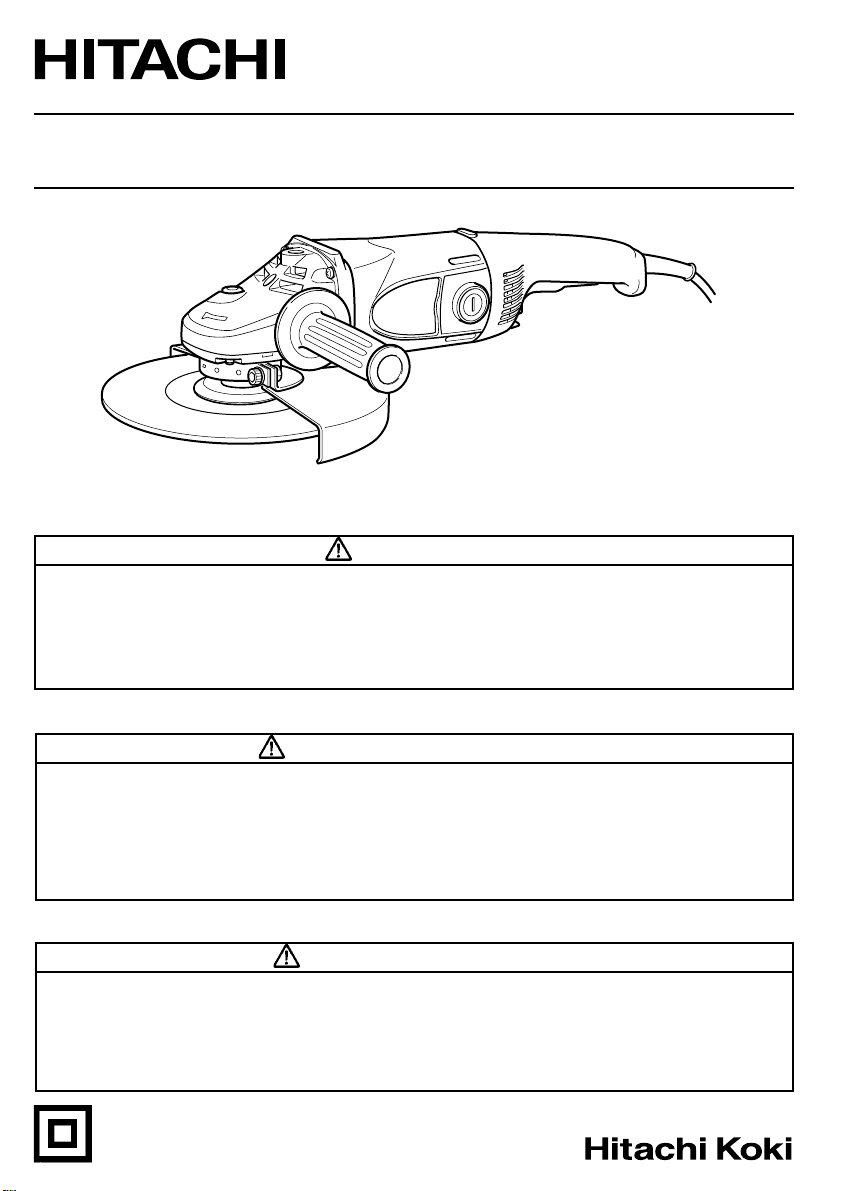
Model Disc Grinder
Modèle Meuleuse
Modelo Amoladora angular
G 18SR • G 23SR
G23SR
SAFETY INSTRUCTIONS AND INSTRUCTION MANUAL
WARNING
IMPROPER OR UNSAFE use of this power tool can result in death or serious bodily
injury!
This manual contains important information about product safety. Please read and
understand this manual BEFORE operating the power tool. Please keep this manual
available for other users and owners before they use the power tool.
This manual should be stored in safe place.
INSTRUCTIONS DE SECURITE ET MODE D’EMPLOI
AVERTISSEMENT
Une utilisation INCORRECTE OU DANGEREUSE de cet outil motorisé peut entraîner la
mort ou de sérieuses blessures corporelles !
Ce mode d’emploi contient d’importantes informations à propos de la sécurité de ce
produit. Prière de lire et de comprendre ce mode d’emploi AVANT d’utiliser l’outil
motorisé. Garder ce mode d’emploi à la disponibilité des autres utilisateurs et
propriétaires avant qu’ils utilisent l’outil motorisé.
Ce mode d’emploi doit être conservé dans un endroit sûr.
INSTRUCCIONES DE SEGURIDAD Y MANUAL DE INSTRUCCIONES
ADVERTENCIA
¡La utilización INAPROPIADA O PELIGROSA de esta herramienta eléctrica puede resultar
en lesiones de gravedad o la muerte!
Este manual contiene información importante sobre la seguridad del producto. Lea y
comprenda este manual ANTES de utilizar la herramienta eléctrica. Guarde este manual
para que puedan leerlo otras personas antes de utilizar la herramienta eléctrica.
Este manual debe ser guardado en un lugar seguro.
DOUBLE INSULATION
DOUBLE ISOLATION
AISLAMIENTO DOBLE

English
IMPORTANT SAFETY INFORMATION ......3
MEANINGS OF SIGNAL WORDS ..............3
SAFETY............................................................4
GENERAL SAFETY RULES .........................4
SPECIFIC SAFETY RULES AND
SYMBOLS.............................................. 6
DOUBLE INSULATION FOR SAFER
OPERATION .......................................... 8
FUNCTIONAL DESCRIPTION .......................10
NAME OF PARTS ......................................10
SPECIFICATIONS ...................................... 10
CONTENTS
Page Page
ASSEMBLY AND OPERATION..................... 11
APPLICATIONS .........................................11
PRIOR TO OPERATION ............................. 11
GRINDER OPERATION .............................13
DEPRESSED CENTER WHEEL
ASSEMBLY AND DISASSEMBLY......14
MAINTENANCE AND INSPECTION.............15
ACCESSORIES .............................................. 17
STANDARD ACCESSORIES ..................... 17
OPTIONAL ACCESSORIES .......................17
PARTS LIST ...................................................49
Français
INFORMATIONS IMPORTANTES DE
SÉCURITÉ............................................18
SIGNIFICATION DES MOTS
D’AVERTISSEMENT ........................... 18
SECURITE ...................................................... 19
REGLES GENERALE DE SECURITE .........19
REGLES DE SECURITE SPECIFIQUES
ET SYMBOLES .................................... 21
DOUBLE ISOLATION POUR UN
FONCTIONNEMENT PLUS SUR ........ 24
DESCRIPTION FONCTIONNELLE ................25
NOM DES PARTIES ..................................25
SPECIFICATIONS ...................................... 25
TABLE DES MATIERES
Page Page
Español
INFORMACIÓN IMPORTANTE SOBRE
SEGURIDAD ........................................ 33
SIGNIFICADO DE LAS PALABRAS DE
SEÑALIZACIÓN................................... 33
SEGURIDAD ..................................................34
NORMAS GENERALE DE SEGURIDAD ... 34
NORMAS Y SÍMBOLOS ESPECÍFICOS DE
SEGURIDAD ........................................ 36
AISLAMIENTO DOBLE PARA OFRECER
UNA OPERACIÓN MÁS SEGURA ..... 39
DESCRIPCIÓN FUNCIONAL .........................40
NOMENCLATURA..................................... 40
ESPECIFICACIONES.................................. 40
Página Página
ASSEMBLAGE ET FONCTIONNEMENT......26
UTILISATIONS ..........................................26
AVANT L’UTILISATION ............................ 26
UTILISATION DE LA MEULEUSE ............28
ASSEMBLAGE ET DESASSEMBLAGE
DE LA MEULE A DEPRESSION
CENTRALE ..........................................29
ENTRETIEN ET INSPECTION ....................... 30
ACCESSOIRES .............................................. 32
ACCESSOIRES STANDARD ..................... 32
ACCESSOIRES SUR OPTION ...................32
LISTE DES PIECES ........................................49
ÍNDICE
MONTAJE Y OPERACIÓN ............................ 41
APLICACIONES ......................................... 41
ANTES DE LA OPERACIÓN ...................... 41
OPERACIÓN DE LA AMOLADORA
ANGULAR ........................................... 43
MONTAJE Y DESMONTAJE DE LA
RUEDA DE DISCO ABOMBADO ........44
MANTENIMIENTO E INSPECCIÓN .............. 46
ACCESORIOS ................................................48
ACCESORIOS ESTÁNDAR .......................48
ACCESORIOS OPCIONALES .................... 48
LISTA DE PEIZAS .......................................... 49

English
IMPORTANT SAFETY INFORMATION
Read and understand all of the safety precautions, warnings and operating instructions in
the Instruction Manual before operating or maintaining this power tool.
Most accidents that result from power tool operation and maintenance are caused by the
failure to observe basic safety rules or precautions. An accident can often be avoided by
recognizing a potentially hazardous situation before it occurs, and by observing appropriate
safety procedures.
Basic safety precautions are outlined in the “SAFETY” section of this Instruction Manual
and in the sections which contain the operation and maintenance instructions.
Hazards that must be avoided to prevent bodily injury or machine damage are identified by
WARNINGS on the power tool and in this Instruction Manual.
NEVER use this power tool in a manner that has not been specifically recommended by
HITACHI.
MEANINGS OF SIGNAL WORDS
WARNING indicates a potentially hazardous situations which, if ignored, could result in
death or serious injury.
CAUTION indicates a potentially hazardous situations which, if not avoided, may result in
minor or moderate injury, or may cause machine damage.
NOTE emphasizes essential information.
3

English
SAFETY
GENERAL SAFETY RULES
WARNING: Read all instructions
Failure to follow all instructions listed below may result in electric shock,
fire and/or serious injury.
The term “power tool” in all of the warnings listed below refers to your
mains-operated (corded) power tool or battery-operated (cordless)
power tool.
SAVE THESE INSTRUCTIONS
1) Work area safety
a) Keep work area clean and well lit.
Cluttered or dark areas invite accidents.
b) Do not operate power tools in explosive atmospheres, such as in the presence of
flammable liquids, gases or dust.
Power tools create sparks which may ignite the dust of fumes.
c) Keep children and bystanders away while operating a power tool.
Distractions can cause you to lose control.
2) Electrical safety
a) Power tool plugs must match the outlet.
Never modify the plug in any way.
Do not use any adapter plugs with earthed (grounded) power tools.
Unmodified plugs and matching outlets will reduce risk of electric shock.
b) Avoid body contact with earthed or grounded surfaces such as pipes, radiators,
ranges and refrigerators.
There is an increased risk of electric shock if your body is earthed or grounded.
c) Do not expose power tools to rain or wet conditions.
Water entering a power tool will increase the risk of electric shock.
d) Do not abuse the cord. Never use the cord for carrying, pulling or unplugging the
power tool.
Keep cord away from heat, oil, sharp edges or moving parts.
Damaged or entangled cords increase the risk of electric shock.
e) When operating a power tool outdoors, use an extension cord suitable for outdoor
use.
Use of a cord suitable for outdoor use reduces the risk of electric shock.
3) Personal safety
a) Stay alert, watch what you are doing and use common sense when operating a
power tool.
Do not use a power tool while you are tired or under the influence of drugs, alcohol
or medication.
A moment of inattention while operating power tools may result in serious personal
injury.
4

b) Use safety equipment. Always wear eye protection.
Safety equipment such as dust mask, non-skid safety shoes, hard hat, or hearing
protection used for appropriate conditions will reduce personal injuries.
c) Avoid accidental starting. Ensure the switch is in the off position before plugging in.
Carrying power tools with your finger on the switch or plugging in power tools that
have the switch on invites accidents.
d) Remove any adjusting key or wrench before turning the power tool on.
A wrench or a key left attached to a rotating part of the power tool may result in
personal injury.
e) Do not overreach. Keep proper footing and balance at all times.
This enables better control of the power tool in unexpected situations.
f) Dress properly. Do not wear loose clothing or jewellery. Keep your hair, clothing
and gloves away from moving parts.
Loose clothes, jewellery or long hair can be caught in moving parts.
g) If devices are provided for the connection of dust extraction and collection facilities,
ensure these are connected and properly used.
Use of these devices can reduce dust-related hazards.
4) Power tool use and care
a) Do not force the power tool. Use the correct power tool for your application.
The correct power tool will do the job better and safer at the rate for which it was designed.
b) Do not use the power tool if the switch does not turn it on and off.
Any power tool that cannot be controlled with the switch is dangerous and must be
repaired.
c) Disconnect the plug from the power source and/or the battery pack from the power
toll before making any adjustments, changing accessories, or storing power tools.
Such preventive safety measures reduce the risk of starting the power tool accidentally.
d) Store idle power tools out of the reach of children and do not allow persons
unfamiliar with the power tool or these instructions to operate the power tool.
Power tools are dangerous in the hands of untrained users.
e) Maintain power tools. Check for misalignment or binding of moving parts, breakage
of parts and any other condition that may affect the power tools operation.
If damaged, have the power tool repaired before use.
Many accidents are caused by poorly maintained power tools.
f) Keep cutting tools sharp and clean.
Properly maintained cutting tools with sharp cutting edges are less likely to bind
and are easier to control.
g) Use the power tool, accessories and tool bits etc., in accordance with these
instructions and in the manner intended for the particular type of power tool,
taking into account the working conditions and the work to be performed.
Use of the power tool for operations different from intended could result in a
hazardous situation.
5) Service
a) Have your power tool serviced by a qualified repair person using only identical
replacement parts.
This will ensure that the safety of the power tool is maintained.
English
–WARNING– To reduce the risk of injury, user must read instruction manual.
5
English
SPECIFIC SAFETY RULES AND SYMBOLS
1. ALWAYS use proper guard with grinding wheel. A guard protects operator from broken
wheel fragments.
2. Accessories must be rated for at least the speed recommended on the tool warning
label. Wheels and other accessories running over rated speed can fly apart and cause
injury.
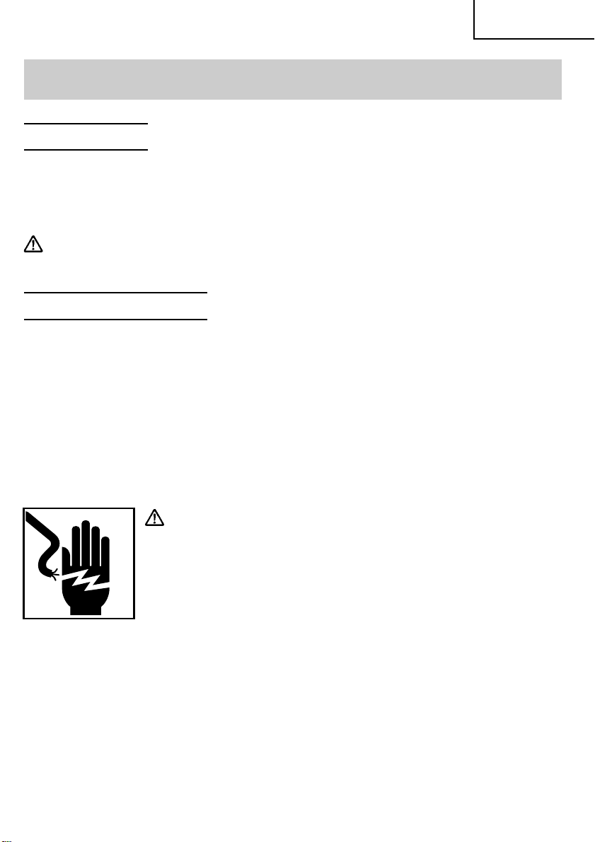
3. Hold tools by insulated gripping surfaces when performing an operation where the
cutting tool may contact hidden wiring or its own cord. Contact with a “live” wire will
make exposed metal parts of the tool “live” and shock the operator.
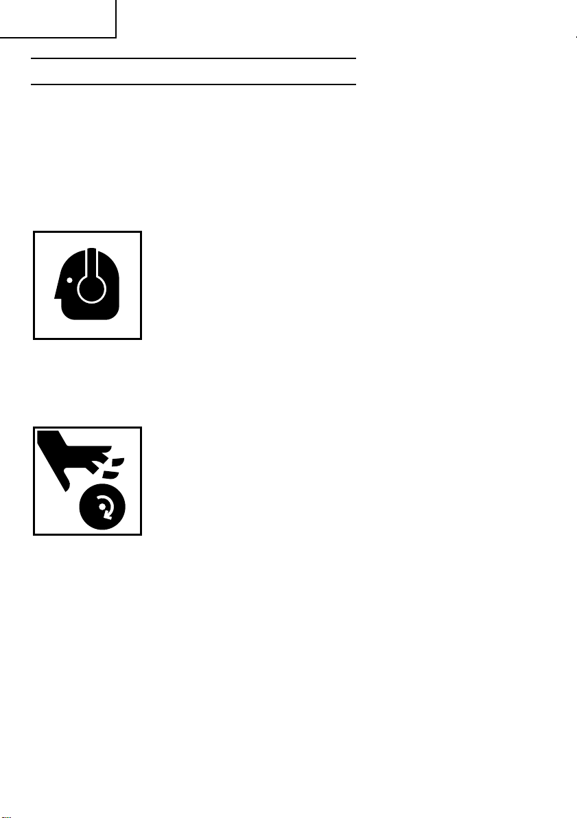
4. ALWAYS wear ear protectors when using the tool for extended periods.
Prolonged exposure to high intensity noise can cause hearing loss.
5. Use only a depressed center wheel with a rated capacity which is GREATER than 6,600
RPM. Using any wheel a rated capacity LESS than 6,600 RPM and/or an incorrect sized
wheel (see SPECIFICATIONS at page 10) may result in wheel breakage, flying wheel
fragments, and resulting in death or serious injury.
6. NEVER touch moving parts.
NEVER place your hands, fingers or other body parts near the tool’s
moving parts.
7. NEVER operate without all guards in place.
NEVER operate this tool without all guards or safety features in place and in proper
working order. If maintenance or servicing requires the removal of a guard or safety
feature, be sure to replace the guard or safety feature before resuming operation of the
tool.
8. Use right tool.
Don’t force small tool or attachment to do the job of a heavy-duty tool.
Don’t use tool for purpose not intended —for example— don’t use circular saw for
cutting tree limbs or logs.
9. NEVER use a power tool for applications other than those specified.
NEVER use a power tool for applications other than those specified in the Instruction
Manual.
6

English
10. Handle tool correctly.
Operate the tool according to the instructions provided herein. Do not drop or throw
the tool. NEVER allow the tool to be operated by children, individuals unfamiliar with
its operation or unauthorized personnel.
11. Keep all screws, bolts and covers tightly in place.
Keep all screws, bolts, and plates tightly mounted. Check their condition periodically.
12. Do not use power tools if the plastic housing or handle is cracked.
Cracks in the tool’s housing or handle can lead to electric shock. Such tools should not
be used until repaired.
13. Blades and accessories must be securely mounted to the tool.
Prevent potential injuries to youself or others. Blades, cutting implements and
accessories which have been mounted to the tool should be secure and tight.
14. Keep motor air vent clean.
The tool’s motor air vent must be kept clean so that air can freely flow at all times.
Check for dust build-up frequently.
15. Operate power tools at the rated voltage.
Operate the power tool at voltages specified on its nameplate.
If using the power tool at a higher voltage than the rated voltage, it will result in
abnormally fast motor revolution and may damage the unit and the motor may burn
out.
16. NEVER use a tool which is defective or operating abnormally.
If the tool appears to be operating unusually, making strange noises, or otherwise
appears defective, stop using it immediately and arrange for repairs by a Hitachi
authorized service center.
17. NEVER leave tool running unattended. Turn power off.
Don’t leave tool until it comes to a complete stop.
18. Carefully handle power tools.
Should a power tool be dropped or struck against hard materials inadvertently, it may
be deformed, cracked, or damaged.
19. Do not wipe plastic parts with solvent.
Solvents such as gasoline, thinner benzine, carbon tetrachloride, and alcohol may
damage and crack plastic parts. Do not wipe them with such solvents.
Wipe plastic parts with a soft cloth lightly dampened with soapy water and dry
thoroughly.
20. NEVER use a depressed center wheel which is cracked or deformed or worn away (see
the MAINTENANCE AND INSPECTION section on page 15).
21. NEVER use the grinder in places where the sparks generated by the grinder can cause
explosion, such as where flammable materials or gases are present.
22. NEVER push in the push button while the spindle is running.
23. ALWAYS wear eye protection that meets the requirement of the latest revision of ANSI
Standard Z87.1.
7

English
24. ALWAYS wear a mask or respirator to protect yourself from dust or potentially harmful
particles generated during the grinding operation.
25. ALWAYS firmly grip the body handle and side handle while operating the grinder.
26. ALWAYS have a trial run before grinding commence (see “Test the grinder before
using” on page 12).
27. ALWAYS follow the instructions contained in this manual when replacing the depressed
center wheel.
28. ALWAYS be careful with buried object such as an underground wiring.
Touching these active wiring or electric cable with this tool, you may receive an electric
shock.
Comfirm if there are any buried object such as electric cable within the wall, floor or
ceiling where you are going to operate here after.
29. Definitions for symbols used on this tool
V ............ volts
Hz ..........hertz
A............amperes
no .......... no load speed
W...........watt
...........Class II Construction
---/min ...revolutions per minute
DOUBLE INSULATION FOR SAFER OPERATION
To ensure safer operation of this power tool, HITACHI has adopted a double insulation
design. “Double insulation “ means that two physically separated insulation systems have
been used to insulate the electrically conductive materials connected to the power supply
from the outer frame handled by the operator. Either the symbol “
insulation” appear on the power tool or on the nameplate.
Although this system has no external grounding, you must still follow the normal electrical
safety precautions given in this Instruction Manual, including not using the power tool in
wet environments.
To keep the double insulation system effective, follow these precautions:
䡬 Only HITACHI AUTHORIZED SERVICE CENTER should disassemble or assemble this
power tool, and only genuine HITACHI replacement parts should be installed.
䡬 Clean the exterior of the power tool only with a soft cloth moistened with soapy water,
and dry thoroughly.
Never use solvents, gasoline or thinners on plastic components; otherwise the plastic
may dissolve.
8
” or the words “Double

SAVE THESE INSTRUCTIONS
AND
MAKE THEM AVAILABLE TO
OTHER USERS AND OWNERS
OF THIS TOOL!
English
9
English
FUNCTIONAL DESCRIPTION
NOTE: The information contained in this Instruction Manual is designed to assist you in
the safe operation and maintenance of the power tool.
NEVER operate, or attempt any maintenance on the tool unless you have first read
and understood all safety instructions contained in this manual.
Some illustrations in this Instruction Manual may show details or attachments that
differ from those on your own power tool.
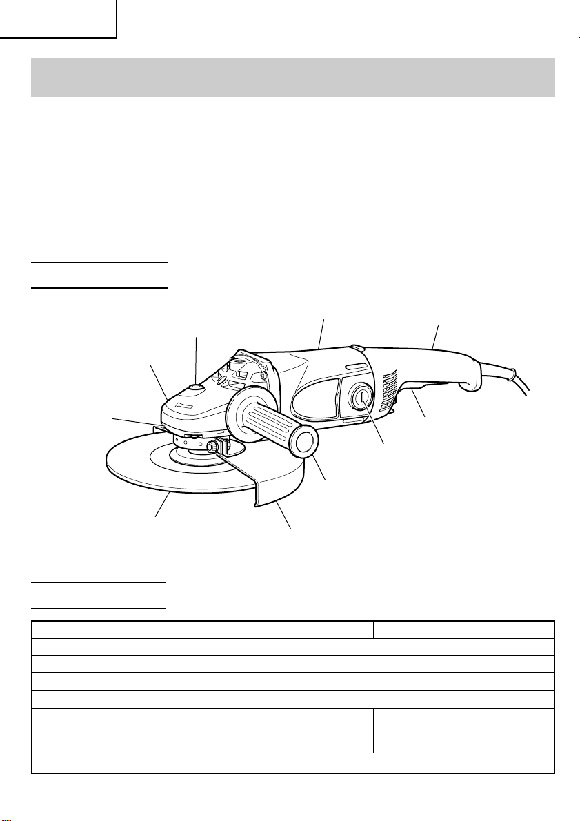
NAME OF PARTS
Push button
Gear cover
Packing gland
Depressed center wheel
Housing
Brush cap
Side handle
Wheel guard
Fig. 1
Handle
Switch
SPECIFICATIONS
Model G18SR G23SR
Motor Single-Phase Series Commutator Motor
Power Source Single-Phase 120 V AC 60 Hz / DC
Current 15 A
No-Load Speed 6,000/min
Wheel Size:
External diam. 7" (180 mm) 9" (230 mm)
Hole diam. 7/8" (22 mm) 7/8" (22 mm)
Weight 9.5 lbs (4.3 kg)
10
English
ASSEMBLY AND OPERATION
APPLICATIONS
䡬 Removal of casting fin and finishing of various type of steel, bronze and aluminum
materials and castings.
䡬 Grinding of welded sections or sections cut by means of an acetylene torch.
䡬 Grinding of synthetic resins, slate, brick, marble.
WARNING: To avoid the risk of serious injury, NEVER use this grinder with cup
wheels and/or saw blades.
PRIOR TO OPERATION
1. Power source
Ensure that the power source to be utilized conforms to the power source requirements
specified on the product nameplate.
2. Power switch
Ensure that the switch is in the OFF position. If the plug is connected to a receptacle
while the switch is in the ON position, the power tool will start operating immediately
and can cause serious injury.
3. Extension cord
When the work area is far away from the power source, use an extension cord of
sufficient thickness and rated capacity. The extension cord should be kept as short as
practicable.
WARNING: Damaged cord must be replaced or repaired.
4. Check the receptacle
If the receptacle only loosely accepts the plug, the receptacle must be repaired. Contact
a licensed electrician to make appropriate repairs.
If such a fautly receptacle is used, it may cause overheating, resulting in a serious
hazard.
5. Check your work environment
Ensure the following before operation;
䡬 No flammable gas, liquid, or object at worksite.
䡬 When grinding thin steel sheet it may cause a high booming noise.
To avoid such noise, place a rubber mat under the workpiece.
䡬 Clear the area of children or unauthorized personnel.
11
English
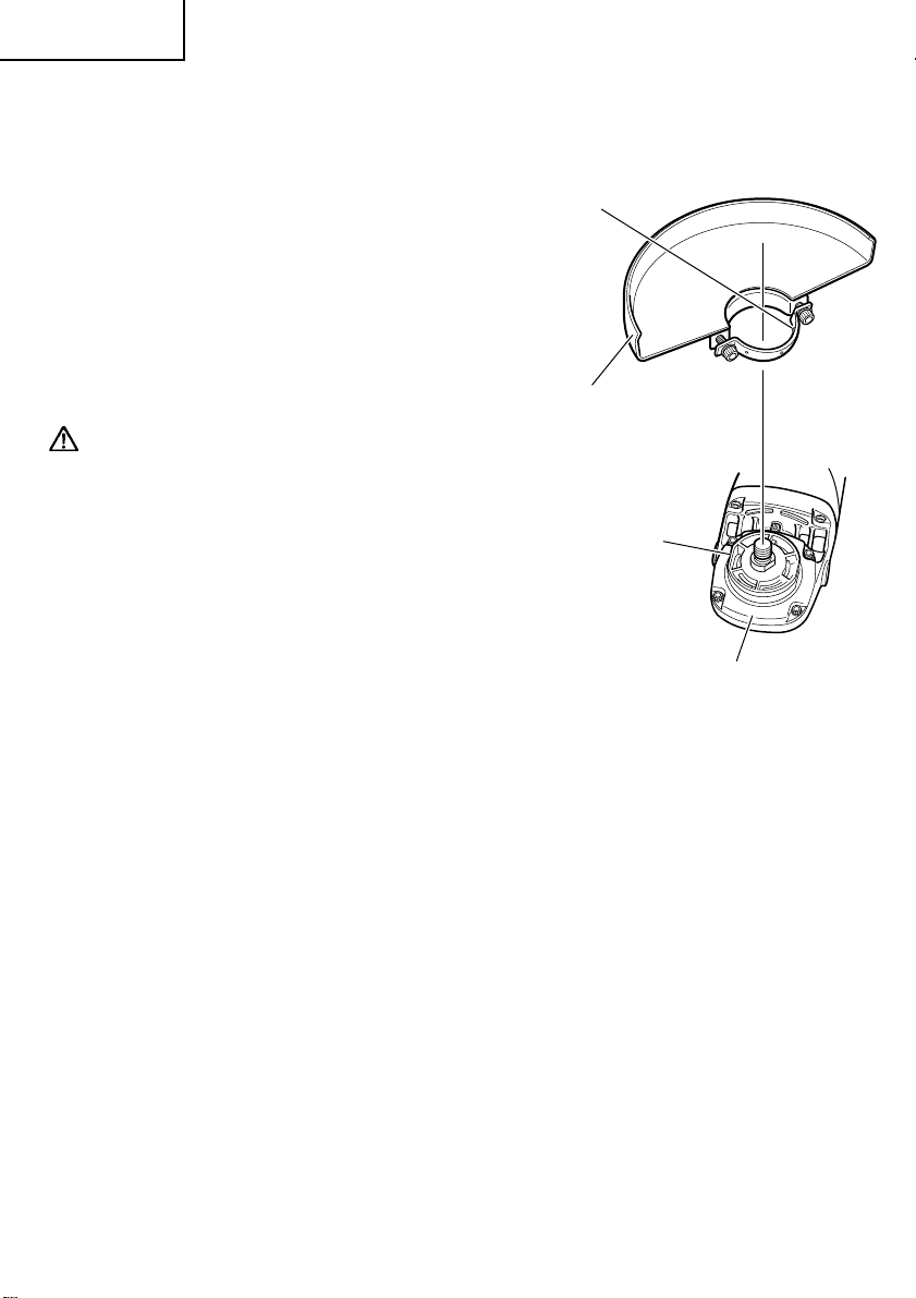
6. Mounting the wheel guard
Be sure to mount the wheel guard at an angle that will protect the operator’s body from
injury by a broken wheel piece.
[Installing and adjusting the wheel guard]
䡬 Slightly loosen the screw on the wheel
guard.
䡬 Install the wheel-guard-locating pin in line
with the across flats of the packing gland,
turn it to the angle suitable for operation,
and make adjustment.
䡬 After the adjustment, ensure that the screw
is securely tightened on the wheel guard
in order to fix it completely.
Locating pin
Wheel guard
WARNING: If the wheel guard is not
attached properly, a broken
wheel may result in and
cause death or serious
injury.
7. Thoroughly check that the depressed
center wheel is free of cracks, splits and
other abnomalities before mounting.
Make sure it is firmly clamped and has
been properly mounted. Refer to page
14 of this manual for Depressed Center
Wheel Assembly and Disassembly.
8. Test the grinder before using
Before actually beginning the grinding work, test the grinder by first clearing the area
of all other personnel. Make sure the wheel guard is in place and that you are wearing
eye protection. Turn the grinder “on”, and make sure the grinder runs smoothly and
shows no abnormalities.
Duration of the trial run is as follows:
When depressed center wheel is replaced .................. 3 minutes or more
When starting daily work .............................................. 1 minute or more
9. Use only properly rated depressed center wheels
Use only depressed center wheels rated at 6,600 RPM or more.
Using a depressed center wheel rated less can lead to wheel disintegration during
operation and cause serious bodily injury.
10. Check the push button
Make sure that the push button is disengaged by pushing push button two or three
times before turning on the grinder. (Fig. 5)
Across flats
Packing gland
Fig. 2
12
GRINDER OPERATION
1. Hold the grinder firmly by its handle and side handle (Fig. 1)
The grinder produces a counterforce which must be controlled by firmly holding onto
the grinder.
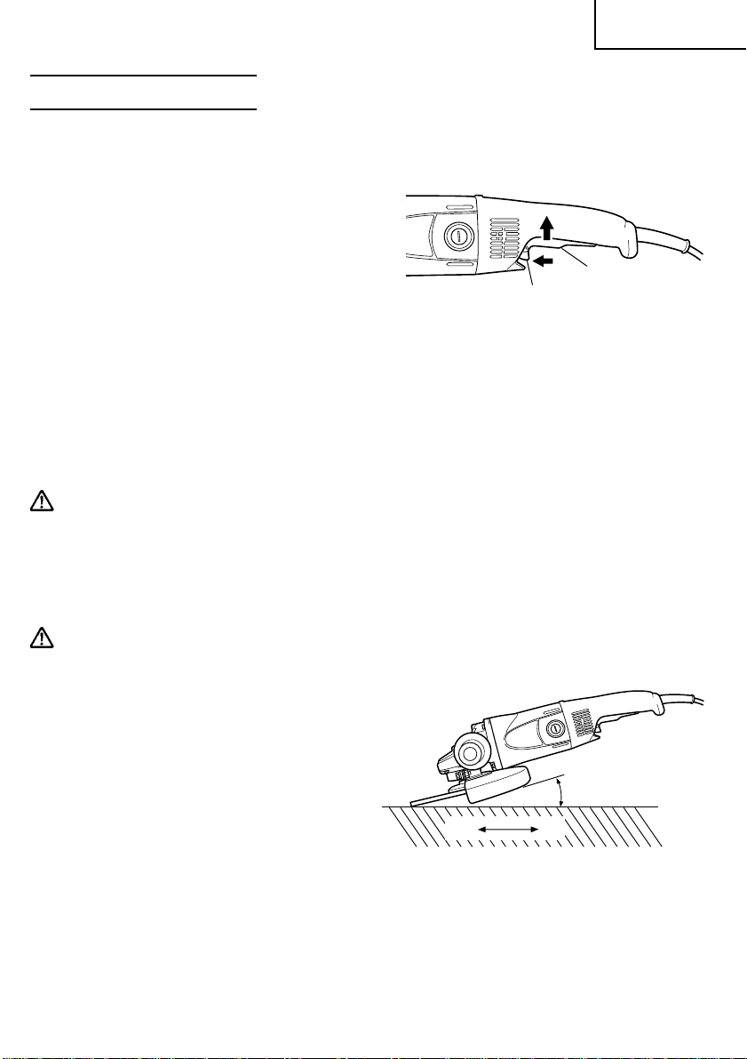
2. Turn the grinder “on” (Fig. 3)
While holding the grinder firmly, use one
finger to switch to the “on” position.
Switch ON: Push the locking button forward
and then press the switch lever.
*For continuous use, press the
switch lever. The switch lever
is locked by pushing the
locking button forward once
again.
(*Subject to change depending on area.)
Switch OFF: Press and release the switch lever.
Locking
button
Fig. 3
Switch
lever
3. Use light grinding pressure
There is no need to press hard when grinding. Usually the grinder’s own weight is
sufficient to allow the required light contact with the surface to be ground.
WARNING: Do not press the grinder forcibly against the surface to be ground. Heavy
pressure can result in wheel breakage and serious injury. It can also
damage the surface being ground or damage the grinder’s motor.
English
4. Use proper grinding angle
Grind only with the wheel’s edge by lifting the grinder 15° to 30°, as shown in Fig. 4.
CAUTION:
● Do not use the entire surface of the depressed center wheel. Use only the edge of the
depressed center wheel.
5. Move the grinder in the proper direction
When using a new depressed center wheel
in direction A (Fig. 4), the wheel edge may
cut into the workpiece. In this case, grind
in direction B (Fig. 4).
Once the wheel edge is worn, the workpiece
can be ground in both directions.
NOTE: The wheel provided (resinoid wheel) is rated as Class A grain and # 24 grain size. It
is most suitable for heavy grinding of steel and other types of materials.
AB
15°–30°
Fig. 4
6. Adjust operation to desired finish
For a fine finish, decrease pressure by lifting slightly. Grind slowly and at the appropriate
speed.
13
English
CAUTION:
● The revolving depressed center wheel will create air turbulence.
Do no lay the grinder down in areas of dust or dirt until it has come to a complete
stop.
DEPRESSED CENTER WHEEL ASSEMBLY AND DISASSEMBLY
WARNING: Never attempt to assemble or disassemble the depressed center wheel,
unless the power switch is in the “OFF” position and the electrical
cord has been disconnected from the receptacle.
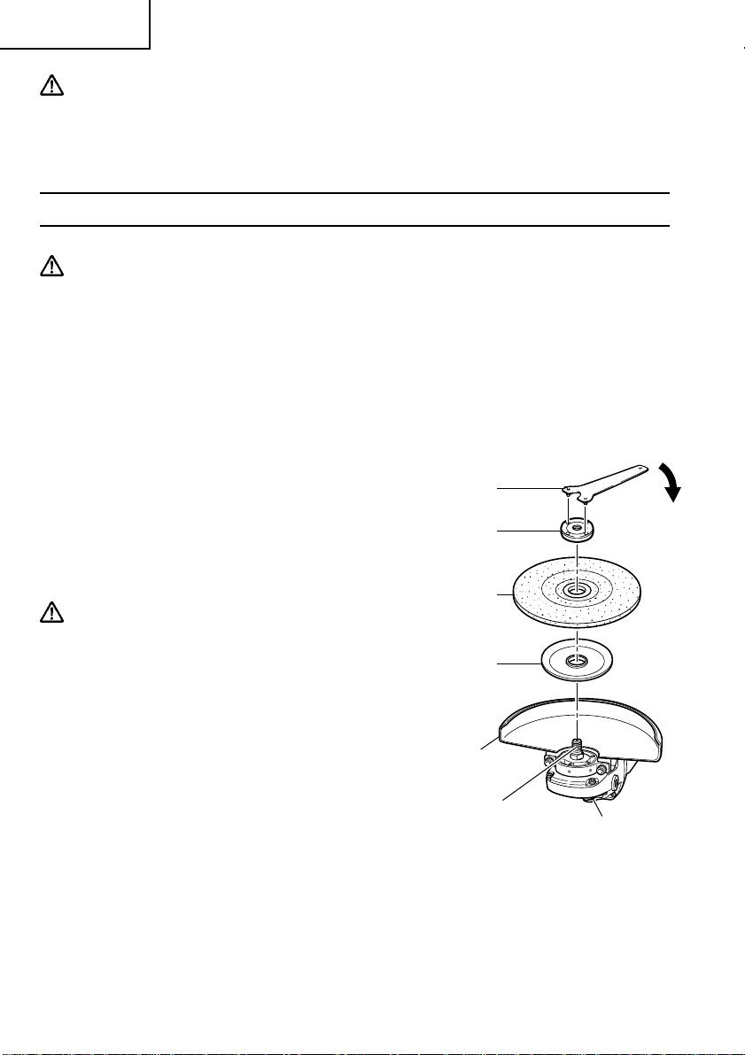
1. Assembly
(1) Turn the disc grinder upsidedown so that the spindle is facing upward.
(2) Align the oval-shaped indentation of the wheel washer with the notched part of the
spindle, then attach them.
(3) Fit the protuberance of the depressed center wheel onto the wheel washer.
(4) Screw the wheel nut onto the spindle.
(5) While pushing the push button with
one hand, lock the spindle by turning
the depressed center wheel slowly with
the other hand.
Tighten the wheel nut by using the
supplied wrench as shown in Fig. 5.
Wrench
Tighten
Wheel nut
CAUTION:
● Tighten the wheel nut securely and confirm
that the depressed center wheel does not
wobble.
2. Disassembly
To remove the depressed center wheel,
simply reverse the above-mentioned
procedure.
14
Depressed
center wheel
Wheel
washer
Wheel
guard
Spindle
Push
button
Fig. 5
English
MAINTENANCE AND INSPECTION
WARNING: Be sure to switch power OFF and disconnect the plug from the receptacle
during maintenance and inspection.
Using cracked, deformed or damaged wheels can lead to wheel
breakage and resulting serious injury.
1. Replacing the depressed center wheel
Replace the depressed center wheel when it has been worn out to about 2-3/8" (60mm)
in external diameter. Confirm that there is no crack or any damage to the depressed
center wheel. If there is a crack or a transformation in the wheel, replace it immediately.
2. Inspecting the screws
Regularly inspect all screws and ensure that they are fully tightened. Should any of the
screws be loosened, retighten them immediately.
WARNING: Using this grinder with loosened screws is extremely dangerous.
3. Confirm that there is no damage in the wheel guard, the electrical cord and the
housing, etc.
Check that the on/off switch operates normally.
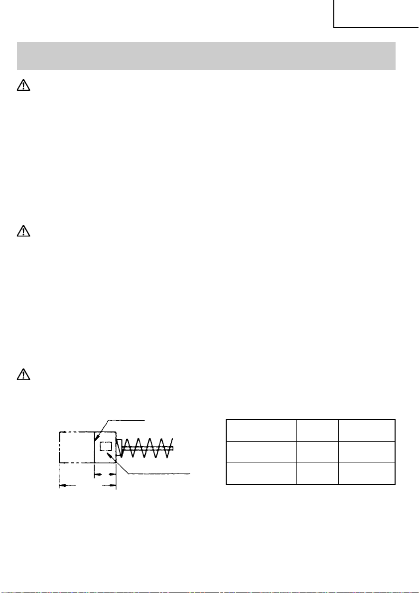
4. Inspecting the carbon brushes (Fig. 6)
The Motor employs carbon brushes which are consumable parts. When they become
worn to or near the “wear limit”, it could result in motor trouble. When an auto-stop
carbon brush is equipped, the motor will stop automatically. At that time, replace both
carbon brushes with new ones which have the same carbon brush Numbers shown in
the figure. In addition, always keep carbon brushes clean and ensure that they slide freely
within the brush holders.
CAUTION: Using this grinder with a carbon brush which is worn in excess of the wear
limit will damage the motor.
Wear limit
No. of
carbon brush
Usual carbon 0.24"
brush (6 mm)
No. of carbon brush
a
0.67"
(17 mm)
Fig. 6
NOTE: Use HITACHI carbon brush No. 44 or 74 indicated in Fig. 6.
Auto-stop 0.28"
carbon brush (7 mm)
a
44
74
15

English
䡬 Replacing carbon brushes:
Disassemble the brush cap with a slotted-head screwdriver. The carbon brush can then
be easily removed.
5. Service and repairs
All quality power tools will eventually require servicing or replacement of parts because
of wear from normal use. To assure that only authorized replacement parts will be
used, all service and repairs must be performed by a HITACHI AUTHORIZED SERVICE
CENTER, ONLY.
6. Service parts list
A: Item No.
B: Code No.
C: No. Used
D: Remarks
CAUTION:
● Repair, modification and inspection of Hitachi Power Tools must be carried out by a
Hitachi Authorized Service Center.
This Parts List will be helpful if presented with the tool to the Hitachi Authorized
Service Center when requesting repair or other maintenance.
In the operation and maintenance of power tools, the safety regulations and standards
prescribed in each country must be observed.
MODIFICATIONS: Hitachi Power Tools are constantly being improved and modified to
incorporate the latest technological advancements.
Accordingly, some parts (i.e. code numbers and/or design) may be
changed without prior notice.
16
 Loading...