

Page 1

SM0313
ED-X31EP(C14B-20)
SERVICE MANUAL
ED-X33EP(C14B-20)
ED-X31GEP(C14D-20)
ED-X33GEP(C14D-20)
Warning
The technical information and parts shown in this
manual are not to be used for: the development,
design, production, storage or use of nuclear, chemical,
biological or missile weapons or other weapons of
mass destruction; or military purposes; or purposes that
endanger global safety and peace. Moreover, do not
sell, give, or export these items, or grant permission for
use to parties with such objectives. Forward all inquiries
to Hitachi Ltd.
Caution
Be sure to read this manual before servicing. To assure safety from fi re, electric shock, injury, harmful
radiation and materials, various measures are provided in this Hitachi Multimedia LCD Projector.
Be sure to read cautionary items described in the manual to maintain safety before servicing.
Service Warning
1. When replacing the lamp, avoid burns to your fi ngers,the lamp becomes very hot.
2. Never touch the lamp bulb with a fi nger or anything else. Never drop it or give it a shock. They may
cause bursting of the bulb.
3. This projector is provided with a high voltage circuit for the lamp. Do not touch the electric parts of
the power unit (circuit) or the power unit (ballast) after turning on the projector.
4. Do not touch the exhaust fan during operation.
5. The LCD module assembly is likely to be damaged. If replacing the LCD LENS/PRISM assembly,
do not hold the FPC of the LCD module assembly.
6. Use the cables which are included with the projector or as specifi ed.
Contents
1. Features ------------------------------------------------------ 2
2. Specifi cations ----------------------------------------------- 2
3. Names of each part---------------------------------------- 4
4. Adjustment---------------------------------------------------7
5. Troubleshooting ------------------------------------------ 14
6. Service points --------------------------------------------- 19
7. Wiring diagram-------------------------------------------- 34
8. Disassembly diagram ----------------------------------- 43
9. Replacement parts list ---------------------------------- 51
10. RS-232C communication ------------------------------ 52
11. Block diagram --------------------------------------------- 72
12. Connector connection diagram ----------------------- 73
13. Basic circuit diagram ------------------------------------ 74
SPECIFICATIONS AND PARTS ARE SUBJECT TO CHANGE FOR IMPROVEMENT.
Multimedia LCD Projector
March 2008
Page 2
ED-X31E / ED-X33E (C14B-20)
1. Features
• High Brightness • Rich Connectivity
• Low Noise • Powerful Sound
2. Specifications
Liquid
crystal
panel
Lamp 220W UHB
Computer
signal
VIDEO
signal
AUDIO
signal
RS232C
USB
(Mouse)
Audio output 7W
Power supply AC100~120V/3.5A, AC220~240V/1.5A
Power consumption 320W
Dimensions 340 (W) x 100 (H) x 270 (D) mm (Not including protruding parts)
Weight 3.5kg
Temperature range
Accessories
Drive system TFT active matrix
Panel size 1.6cm(0.63 type)
Number of pixels 1024 (H) x 768 (V)
Computer IN
Computer OUT
VIDEO IN 1.0Vp-p (75 termination)
S-VIDEO IN
COMPONENT
VIDEO
AUDIO IN 1
AUDIO IN 2
AUDIO IN 3 L/R 200mVrms, 47k or more (max. 2Vrms)
AUDIO OUT output impedance 1k (max. 2Vrms)
INPUT Hi: Max. 20V, Min. 2.6V Lo: Typ. –20.0V, Max. 0.8V
OUTPUT Hi: Typ. 8.0V, Min. 5.0V Lo: Typ. –7.0V, Max. –5.0V
I/O Level
(differential)
1
2
Y 1.0±0.1Vp-p, 75 termination (positive)
B/PB
C
R/PR
C
Amplitude of
differential signal
Amplitude of
signal
Video : Analog 0.7Vp-p(75 termination)
H/V. sync. : TTL level (positive/negative)
Composite sync. : TTL level
Video:Analog 0.7Vp-p, 75 output impedance (positive)
H/V. sync.: TTL level (positive/negative)
Composite sync.: TTL level
Y signal: 1.0±0.1Vp-p, (75 termination)
C signal: 0.286±0.1Vp-p (NTSC burst signal, 75 termination)
0.3±0.1Vp-p (PAL/SECAM burst signal, 75 termination)
0.7±0.1Vp-p, 75 termination (positive)
0.7±0.1Vp-p, 75 termination (positive)
200mVrms, 47k or more (max. 2Vrms)
| (D+) - (D–) | > 0.2V
D+ > 2.8V, D– < 0.3V or D+ > 2.8V, D– < 0.3V
INPUT: “L” = 0.8V or less, “H” = 2.0V or more
OUTPUT: “L” = 0.3V or less, “H” = 2.8V ~ 3.6V
Operation : 5~35°C
Storage : -20~60°C
Remote control x1
RGB cable x 1
Power cords x 2
Batteries x 2
User’s manuals x 1
LENS CAP and STRAP x 1
Audio/Video cable x 1
2
Page 3

ED-X31GE / ED-X33GE (C14D-20)
1. Features
• High Brightness • Rich Connectivity
• Low Noise • Powerful Sound
2. Specifications
Liquid
crystal
panel
Lamp 230W UHB
Computer
signal
VIDEO
signal
AUDIO
signal
RS232C
USB
(Mouse)
Audio output 10W x 1
Power supply AC100~120V/3.5A, AC220~240V/1.5A
Power consumption 320W
Dimensions 340 (W) x 100 (H) x 270 (D) mm (Not including protruding parts)
Weight 3.5kg
Temperature range
Accessories
Drive system TFT active matrix
Panel size 1.6cm(0.63 type)
Number of pixels 1024 (H) x 768 (V)
Computer IN
Computer OUT
VIDEO IN 1.0Vp-p (75 termination)
S-VIDEO IN
COMPONENT
VIDEO
AUDIO IN 1
AUDIO IN 2
AUDIO IN 3 L/R 200mVrms, 47k or more (max. 2Vrms)
AUDIO OUT output impedance 1k (max. 2Vrms)
INPUT Hi: Max. 20V, Min. 2.6V Lo: Typ. –20.0V, Max. 0.8V
OUTPUT Hi: Typ. 8.0V, Min. 5.0V Lo: Typ. –7.0V, Max. –5.0V
I/O Level
(differential)
1
2
Y 1.0±0.1Vp-p, 75 termination (positive)
B/PB
C
R/PR
C
Amplitude of
differential signal
Amplitude of
signal
Video : Analog 0.7Vp-p(75 termination)
H/V. sync. : TTL level (positive/negative)
Composite sync. : TTL level
Video:Analog 0.7Vp-p, 75 output impedance (positive)
H/V. sync.: TTL level (positive/negative)
Composite sync.: TTL level
Y signal: 1.0±0.1Vp-p, (75 termination)
C signal: 0.286±0.1Vp-p (NTSC burst signal, 75 termination)
0.3±0.1Vp-p (PAL/SECAM burst signal, 75 termination)
0.7±0.1Vp-p, 75 termination (positive)
0.7±0.1Vp-p, 75 termination (positive)
200mVrms, 47k or more (max. 2Vrms)
| (D+) - (D–) | > 0.2V
D+ > 2.8V, D– < 0.3V or D+ > 2.8V, D– < 0.3V
INPUT: “L” = 0.8V or less, “H” = 2.0V or more
OUTPUT: “L” = 0.3V or less, “H” = 2.8V ~ 3.6V
Operation : 5~35°C
Storage : -20~60°C
Remote control x1
RGB cable x 1
Power cords x 2
Batteries x 2
User’s manuals x 1
LENS CAP and STRAP x 1
Audio/Video cable x 1
3
Page 4
3. Names of each part
Projector
Ɣ
(1) Lamp cover
The lamp unit is inside.
(2) Focus ring
(3) Zoom ring
(4) Control panel
(5) Elevator buttons (x 2)
(6) Elevator feet (x 2)
(7) Remote sensor
(8) Lens
(9) Lens cover
(10) Intake vents
(11) Filter cover
The air filter and intake vent are
inside.
(12) Speaker
(13) Exhaust vent
(14) AC inlet
(15) Power switch
(16) Rear panel
(17) Security bar
(18) Security slot
ED-X31E / ED-X33E (C14B-20)
HOT!
(6)
(8)
(9)
(13)
HOT!
(4)
(1) (2) (3) (4)
(7)
(6)
(5)
(6)
(12)
(11)
(10)
(6)
(10)
(11)
WARNING
(18)
(16)
(17)
(13)
(1)
ŹHOT! : Do not touch around the lamp cover and the exhaust vents during use
(14)
(15)
or just after use, since it is too hot.
ŹDo not look into the lens or vents while the lamp is on, since the strong light is not good for your
eyes.
ŹDo not handle the elevator buttons without holding the projector, since the projector may drop
down.
CAUTION
ŹMaintain normal ventilation to prevent the projector from heating up. Do not
cover, block or plug up the vents. Do not place anything that can stick or be sucked to the vents,
around the intake vents. Clean the air fi lter periodically.
ŹDo not use the security bar and slot to prevent the projector from falling down, since it is not
designed for it.
4
Page 5
ED-X31E / ED-X33E (C14B-20)
Control panel
(1) STANDBY/ON button
(2) INPUT button
(3) MENU button
It consists of four cursor buttons.
(4) POWER indicator
(5) TEMP indicator
(6) LAMP indicator
Rear panel
(1) AUDIO IN1 port
(2) AUDIO IN2 port
(3) AUDIO OUT port
(4) COMPUTER IN1 port
(5) COMPUTER IN2 port
(6) MONITOR OUT port
(7) Shutdown switch
(8) (4) (5) (6) (7)
(6)
(5)
(4)
(1) (2)(3)
(8) CONTROL port
(9) USB port
(10) COMPONENT
(Y, Cb/Pb, Cr/Pr) ports
(11) VIDEO port
(12) S-VIDEO port
(13) AUDIO IN3 (L,R) ports
(1)
CAUTION
(9) (13) (12) (3)(11) (10)
ŹUse the shutdown switch only when the projector is not turned off by normal procedure,
(2)
since pushing this switch stops operation of the projector without cooling it down.
5
Page 6
Remote control
ED-X31E / ED-X33E (C14B-20)
(1) VIDEO button
(2) COMPUTER button
(3) SEARCH button
(4) STANDBY/ON button
(5) ASPECT button
(6) AUTO button
(7) BLANK button
(8) MAGNIFY - ON button
(9) MAGNIFY - OFF button
(10) MY SOURCE/DOC.CAMERA button
(11) VOLUME - button
(12) PAGE UP button
(13) PAGE DOWN button
(14) VOLUME + button
(15) MUTE button
(16) FREEZE button
(17) MY BUTTON - 1 button
(18) MY BUTTON - 2 button
(19) KEYSTONE button
(20) POSITION button
(21) MENU button
(22) Ÿ/ź/Ż/Ź cursor buttons
(23) ENTER button
(24) ESC button
(25) RESET button
(26) Battery cover
(2)
(1)
(6)
(5)
(16)
(8)
(9)
(19)
(17)
(20)
(22)
(24)
COMPUTER
VIDEO
AUTO
ASPECT SEARCH
FREEZE
MAGNIFY
ON
OFF
KEYSTONE
MY BUTTON
12
POSITION
ENTER
ESC
R007
MY SOURCE/
DOC.CAMERA
PAGE
UP
DOWN
BLANK
VOLUME
MUTE
MENU
RESET
(10)
(4)
(3)
(7)
㧗
(12)
(14)
(11)
(13)
(15)
(18)
(21)
(23)
(25)
Back of
the remote control
WARNING ŹDo not look into the beam outlet and point the beam at people and pets while pressing
the LASER button, since the beam is not good for eyes.
CAUTION Ź
only for pointing on the screen.
Note that the laser beam may result in hazardous radiation exposure. Use the laser pointer
(26)
6
Page 7

ED-X31E / ED-X33E (C14B-20)
4. Adjustment
4-1 Before adjusting
4-1-1 Selection of adjustment
When any parts in the table 4-1 are changed, choose the proper adjusting items with the chart.
Table 4-1: Relation between the replaced part and adjustment
Replaced
part
Dichroic
optics unit
LCD/LENS
prism
assembly
PWB
assembly
Main
Lamp
unit
assembly
Flicker
(Chap.4-2)
Ghost
(Chap.4-3)
: means need for adjustment. : means not need for adjustment.
: means recommended.
Adjustment
DC OFF
(Chap.4-4)
E-POS
(Chap.4-5)
White
balance
(Chap.4-6)
Color
uniformity
(Chap.4-7)
4-1-2 Setting of condition before adjustments
1. Before starting adjustments, warm up projector
for about 10 minutes.
Turn off the automatic keystone function in OPTION
Menu.
If you changed [AUTO KEYSTONE] from [TURN
ON] to [TURN OFF], set to the [TURN ON] after
adjustment.
2. Set Zoom Wide to Max. And project an image
with more than 1m (40 inches) in diagonal size.
3. Set the lens position to the center, using horizontal
and vertical lens shift dials.
4. Normalizing the video adjustments
Press the [MENU] button to display the EASY
menu. If Advanced menu comes up, move to the
Easy menu.
Select the RESET in the EASY menu and press
the [ ] or [ENTER] button to open the RESET dia-
log. Choose the EXECUTE with the [ ] button.
Note that the projector will not allow you to reset
its adjustment values with no signal input.
5. Perform all adjustments from the FACTORY
MENU. Operate as follows to display the FAC-
TORY MENU.
When you use the remote control...
a. Press the [MENU] button of the remote con-
trol to display the Easy menu. (If the Ad-
vanced menu appears, move to the Easy
menu.)
b. Select the RESET in the Easy menu, and
then press the [
] or [ENTER] button.
c. Next, press the [RESET] button one time. And
hold the [RESET] button for 3 seconds or lon-
ger (the FACTORY MENU will appear).
When you use the keypad of the projector...
a. Press the
[ ],
[ ],
[ ]
or [
] button of the pro-
jector to display the Easy menu. (If the Ad-
vanced menu appears, move to the Easy
menu.)
b. Select the RESET in the Easy menu, and
then press the [ ] or [ENTER] button.
c. Next, press the [ ] button one time. And re-
press and hold the [ ] button together with
the [INPUT] button for 3 seconds or more (the
FACTORY MENU will appear).
7
Page 8

ED-X31E / ED-X33E (C14B-20)
4-2 Flicker adjustment
(V.COM adjustment)
Test pattern for the adjustment
128/255
4-3 Ghost adjustment
Test pattern for the adjustment
30%
30%
4-4
DC OFF adjustment
Test pattern for the adjustment
160
/255
0/255
112/255
(vertical bars adjustment 1)
64
/255
88
/255
112
/255
136
/255
160
/255
136
112
/255
/25588/25564/255
Press ENTER key
Adjustment procedure
1.
Use DAC-P - V.COM - R: in the FACTORY
MENU to adjust so that the flicker at the center of
the screen is less than the flicker at the periphery.
(When the flicker is about the same across the
whole screen, adjust so that the flicker at the center
of the screen is somewhat less than elsewhere.)
2. In the same way, use DAC-P - V.COM-G: in the
FACTORY MENU to adjust the G color flicker.
3. In the same way, use DAC-P - V.COM-B: in the
FACTORY MENU to adjust the B color flicker.
NOTE: The test pattern shown on the left sometimes has a horizontal line across the screen.
Adjustment procedure
1. Make this adjustment after completing the ad-
justment in the section 4-2.
Set 0 to the GHOST R, G, B in OPTION-SERVICE-
GHOST Menu.
2.
Use DAC-P - GHOST - R: in the FACTORY MENU
to adjust so that R color ghost is at a minimum.
(Set the adjustment value to default, and then
raise the value. When a ghost appears to the left
of a vertical line, reduce the value by 6 steps.)
3. In the same way, use DAC-P - GHOST-G: in
the FACTORY MENU to adjust so that G color
ghost is at a minimum.
4. In the same way, use DAC-P - GHOST-B: in
the FACTORY MENU to adjust so that B color
ghost is at a minimum.
Adjustment procedure
1. Make this adjustment after completing the ad-
justment in the section 4-3.
2.
Use STRIPE - DCOFF - No. 0 - R : in the FACTO-
RY MENU and use it so that vertical bars are min-
imized.
3. In the same way, use STRIPE - DCOFF - No. 0 -
G : in the FACTORY MENU and use it so that
vertical bars
are minimized.
4. In the same way, use STRIPE - DCOFF - No. 0 -
B : in the FACTORY MENU and use it so that
vertical bars
are minimized.
8
Page 9

ED-X31E / ED-X33E (C14B-20)
4-5
E-POS adjustment (vertical bars adjustment 2)
Test pattern for the adjustment
112/255
4-6
White balance adjustment
Preparations
1. Perform these adjustments after the adjustments described in Section 4-5.
Adjustment procedure
1. First, adjust the G color.
2.
Select GAMMA, SUB-CNT, and G: in the FACTORY
MENU. If the background is white solid, press the
[ENTER] key on the Remote control transmitter to
change to [G] monochrome in the 33-tone grayscale.
3. Adjust GAMMA, SUB-CNT, and G: in the FACTORY MENU so that brightness of 33 steps is
best.
4. Don’t adjust GAMMA, SUB-BRT, and G: in the
FACTORY MENU because we want to keep the
best contrast ratio.
5. Then adjust colors R and B.
(visual inspection)
Adjustment procedure
1. Make this adjustment after completing the ad-
justment in the section 4-4.
2.
Use DAC -P - E-POS - R in the FACTORY MENU
and use it so that vertical bars are minimized.
3. In the same way, select DAC-P - E-POS - G
and use it so that vertical bars
4. In the same way, select DAC-P - E-POS - B
and use it so that vertical bars
2. Reset gamma correction before adjustment.
Place the cursor on [GAMMA] in the FACTORY
MENU, press the [RESET] key and select RESET.
6.
Select GAMMA, SUB-CNT, and G: in the FACTORY
MENU. If the background is white solid, press the
[ENTER] key on the remote control to change to [W]
monochrome in the 33-tone grayscale.
7. Adjust GAMMA, SUB-BRT, R: and B: in the
FACTORY MENU so that low-brightness white
balance is best.
8. Adjust GAMMA, SUB-CNT, R: and B: in the
FACTORY MENU so that middle-brightness
white balance is best.
9. Repeat steps 7 to 8 above, and adjust so that
brightness white balance of 33 steps is best.
are minimized.
are minimized.
9
Page 10

ED-X31E / ED-X33E (C14B-20)
4-7 Color uniformity adjustments
Preparations
1.
Perform these adjustments after the adjustments
described in the section 4-6.
2. Make a color uniformity adjustments for the fol-
lowing tones.
MIN tone (approx. 7% input signal)
MID-1 tone (approx. 14% input signal)
MID-2 tone (approx. 21% input signal)
MID-3 tone (approx. 29% input signal)
MID-4 tone (approx. 36% input signal)
MID-5 tone (approx. 50% input signal)
MID-6 tone (approx. 61% input signal)
MAX tone (approx. 75% input signal)
NOTE: The brightness level of the test patterns
in MID-4 and MID-6 is selectable.
3. Select the [C.UNIF.] in the FACTORY MENU
and press the [
the Adjust Tone menu (shown below) on the
bottom of the screen.
To choose the tone to be adjusted, press the [
] key and then use the [ ] or [ ] key.
Select the major adjustment lattice point No.
and color, and then adjust them.
4. The major adjustment lattice point numbers (a
total of 17 points) corresponds to the major ad-
justment lattice point positions in the diagram
on the right. The color uniformity of the entire
screen can be adjusted by adjusting the white
balance for each of the points starting in order
from the low numbers.
FACTORY MENU
VID-AD
C. UNIF.
DAC-P
GAMMA
STRIPE
OPTION
Adjust tone menu
] key. This operation displays
5. Adjustment point No.1 should not be adjusted,
because it controls the brightness of the entire
screen.
6.
To temporarily turn correction off, place the cur-
sor on [C.UNIF.] in the Adjust Tone menu and
press the [ ] key. The ON/OFF menu appears.
Place the cursor on [ON] with the [ ] key and
press the [ ] key. To turn it on again, place the
cursor on [OFF] and press the [ ] key.
7. Although this adjustment can also be made us-
ing internal signals, we will here use the [EN-
TER] key on the remote control to select the fol-
lowing two signals.
Solid monochrome adjustment color (use G
color adjustment when a color differential me-
ter is used).
Solid white (use for adjustment other than
above).
8. Reset color-shading correction before adjust-
ment.
When resetting all values of 8 tones and all
colors, place the cursor on [C.UNIF.] in the
FACTORY MENU, press the [RESET] key and
select RESET in the dialog.
When resetting only 1 tone, place the cursor
on the tone such as MID-1 to be reset, press
the [RESET] key and select RESET in the di-
alog.
Single tone and monochrome resets cannot
be performed.
Major adjustment lattice point position
14 12
H/6 H/3 H/3 H/6
V/6
6 4 8
V/3
16
C.UNIF
ON/OFF ON
MIN
MID-1
MID-2 ... 6
MAX
OFF
No. 1 R 0
Major adjustment lattice point No.
G 0 B 0
10
10 11
2 1 3
V/3
7 5 9
V/6
15 17
13
Page 11

ED-X31E / ED-X33E (C14B-20)
Adjustment procedure 1
(When a color differential meter is used)
1. First adjust the [MID-1] tone [G:].
2. Select adjustment point [No.2][G:].
When the background is not [G] monochrome,
press the [ENTER] key on the remote control to
switch to solid [G] monochrome.
3. Measure the illumination at adjustment points
No. 2, No.3, No.10 and No.11.
The values should be:
No.2 = Y2 [lx] No.10 = Y10 [lx]
No.3 = Y3 [lx] No.11 = Y11 [lx]
4. No.2 and No.3 adjustment points have the aver-
age of Y2 and Y3.
Y2 = ( Y2 + Y3 ) / 2 ± 2 [%]
Y3 = ( Y2 + Y3 ) / 2 ± 2 [%]
5. No.10 and No.11 adjustment points have the
average of Y10 and Y11.
Y10 = ( Y10 + Y11 ) / 2 ± 2 [%]
Y11 = ( Y10 + Y11 ) / 2 ± 2 [%]
6. Then adjust the [MID-1] tone [R] and [B].
When the background is [G] monochrome,
press the [ENTER] key on the remote control to
switch to solid white.
7. Measure the color coordinates of adjustment
point [No.1] and make a note of them.
Assume that they are x = x1, y = y1.
Note: When the CL-100 color and color differ-
ence meter is used, the [ ¨ ](delta) mode
is convenient. When adjustment point
[No.1] color coordinate has been select-
ed, set the slide switch on the side to
[¨ ](delta) while holding down the [F] but-
ton on the front panel. The measurement
shown after this displays the deviation
from measurement point 1.
8. Measure the color coordinates of measurement
point [No.2] and adjust [No.2][R:] and [B:] so
that the coordinates are as follows.
x = x1 ± 0.005 , y = y1 ± 0.010
9. Similarly, measure adjustment points [No.3] to
[No.17] and adjust their color coordinates start-
ing in order from the small number points.
This completes adjustments required for
[MID-1].
Note: Since excessive correction may lead to a
correction data overview during internal
calculations, use the following values for
reference.
[No.2] to [No.5] ± 40 or less
[No.6] to [No.9] ± 50 or less
[No.10] to [No.13] ± 70 or less
[No.14] to [No.17] ± 120 or less
10. Then adjust the [MIN] tone [G] so that the ad-
justment values are two times as much as
MID-1] tone [G] values.
This completes [G] color adjustments.
11. Then adjust [MIN] tone [R] and [B].
Select [No.2] [B:] and press the [ENTER] key
on the Remote control transmitter to change to
solid white.
12. Measure the color coordinates of adjustment
point [No.1] and make a note of them.
Assume that they are x = x1, y = y1.
13. Now measure the color coordinates of mea-
surement point [No.2] and adjust [No.2][R:] and
[B:] so that the coordinates are as follows.
x = x1 ± 0.005 , y = y1 ± 0.010 (Target)
x = x1 ± 0.020 , y = y1 ± 0.040
14. Similarly, measure adjustment points [No.3] to
[No.17] and adjust their color coordinates start-
ing in order from the small number points.
This completes [MIN] tone adjustments.
15. Now make similar adjustments for [MID-2] tone.
(Adjust [MID-2] tone [G] so that the adjustment
data set half as many as [MID-1] tone [G].)
16. Now make similar adjustments for [MID-3],
[MID-5], [MAX] tones. (It is not necessary to ad-
just the [G] data in these tones.)
17. After completing the step 16, set the value of
the [MID-4] tone [R]: [No.2] to the mean of the
values of the [R]: [No.2] in the [MID-3] and
[MID-4] tones.
18. Set all the values for the [No.2] to [No.17] of
the [MID-4] tone [R] and [B] in the same way as
the step 17.
19. Finally, set the data of the [MID-6] tone [R] and
[B] using the values of the [MID-5] and [MAX]
tones in the same way as the [MID-4] tone [R]
and [B] adjustments in the step 17 and 18.
11
Page 12
ED-X31E / ED-X33E (C14B-20)
Adjustment procedure 2
(visual inspection)
1. First adjust [MIN] tone [G:].
2. Select [No.2] [G:].
If the background is [G] monochrome, press the
[ENTER] key on the remote control to switch to
solid white.
3. View measurement point [No.2] and [No.3].
Lower the [G] color intensity only of the color
point whose [G] color is more intense than
measurement point [No.1].
4. View measurement point [No.10] and [No.11].
Lower the [G] color intensity only of the color
point whose [G] color is more intense than
measurement point [No.1], and raise the inten-
sity of the point whose color intensity is lower
than measurement point [No.1].
5. Now adjust the [MIN] tone for colors [R] and
[B].
6. View measurement points [No.2], [No.3],
[No.10] and [No.11]. Adjust the [R] and [B] of
each measurement point so that they have the
same color as measurement point [No.1].
Adjustment technique:
First, adjust [B:] of the point whose color is to
be adjusted so that it approximates that of
[No.1]. If [R:] is low at this time, the image will
have cyan cast, in which case [R:] is increased.
On the other hand, if [R:] is excessive, the im-
age will have a magenta cast, in which case
[R:] is decreased.
Overall, a cyan cast makes it easy to see color
shading.
7. Next, view measurement points [No.4], [No.5],
[No.12], [No.13] and make similar adjustments.
Then adjust measurement points [No.6], [No.7],
8.
[No.8], [No.9], [No.14], [No.15], [No.16] and [No.17].
This completes the [MIN] tone adjustments.
9. Make similar adjustments for other tones, ex-
cept the [MID-4] and [MID-6] tones, as de-
scribed in steps 1 to 8 above.
No. 2 deviation range No. 10 deviation range No. 3 deviation range No. 11 deviation range
14
10
15
12
6
4
2
1
5
7
13
16
8
3
11
9
17
14
10
15
12
4
6
1
2
5
7
13
16
8
11
3
9
17
14
10
15
12
6
4
2
1
5
7
13
16
8
3
11
9
17
14
10
15
12
4
6
2
1
5
7
13
16
8
3
11
9
17
No. 4 deviation range No. 12 deviation range No. 5 deviation range No. 13 deviation range
14
10
15
12
6
4
1
5
7
13
16
8
3
112
9
17
14
10
15
12
6
4
2
1
5
7
13
16
8
3
11
9
17
14
10
15
12
4
6
1
2
5
7
13
16
8
11
3
9
17
14
10
15
12
4
6
1
2
5
7
13
16
8
3
11
9
17
No. 6 deviation range No. 7 deviation range No. 8 deviation range No. 9 deviation range
14
10
15
12
6
4
1
2
5
7
13
16
8
3
11
9
17
10
15
14
12
6
4
1
2
5
7
13
16
8
11
3
9
17
14
10
15
12
6
4
2
1
5
7
13
16
8
11
3
9
17
14
10
15
12
4
6
2
1
5
5
7
13
16
8
3
11
9
17
No. 14 deviation range No. 15 deviation range No. 16 deviation range No. 17 deviation range
14
12
4
6
16
8
14
12
4
6
16
8
14
12
6
4
16
8
14
12
6
4
16
8
10
15
1
2
5
7
13
11
3
9
17
10
15
2
1
5
7
13
11
3
9
17
10
15
3
1
2
15
10
5
5
7
13
2
1
5
7
13
11
3
9
17
11
9
17
12
Page 13

ED-X31E / ED-X33E (C14B-20)
4-8 Adjusting the zoom and focus
1. Use the zoom ring to adjust the screen size.
2. Use the focus ring to focus the picture.
Focus ring
Zoom ring
13
Page 14
5. Troubleshooting
Check points
ED-X31E / ED-X33E (C14B-20)
14
Page 15

ED-X31E / ED-X33E (C14B-20)
Power can not be turned on
Are
voltage
supplied at pins (8)
and (13) of E800 on the PWB
assembly MAIN in standby
mode?
(8): +6.0V
(13): GND
YES
*: Be sure to unplug the power cord before measuring resistance.
NO
Measure resistance*
between pins (8) and (13) of
E800.
Open
Disconnect TSW
from power unit circuit, and
measure resistance of
TSW.
Short
Power unit (circuit)
0
Open
Fuse on the power unit
(circuit)
PWB assembly MAIN
Power unit (circuit)
Thermal switch (TSW)
Are voltage
supplied at pins (2),
(3), (5), (6) of E800 on the PWB
assembly MAIN in standby
mode?
(2): +14V
(3): GND(for +14V)
YES
(5): +17V
(6): GND(for +17V)
Does
LAMP (DK03) or
TEMP (DK02) indicator light
or blink?
NO
Measure
resistance* between
pins (1) and (2) of S801 when
the lamp door is secure.
0
PWB assembly MAIN
NO
YES
Open
Measure
resistance* between
pins (2) and (3), and between
pins (5) and (6) of
E800.
Open
Power unit (circuit)
Go to the next page
Lamp door
Re-attach lamp
door
Re-attach PWB
assembly MAIN
0
PWB assembly MAIN
Power unit (circuit)
15
Page 16

ED-X31E / ED-X33E (C14B-20)
**: DC fan connectors are E801,
E802, E803, E804 and E805.
Lamp does not light
What
is the state of
LAMP indicator DK03
during operation?
Not light
the PWB assembly MAIN
*: Be sure to unplug the power cord
before measuring resistance.
Light
Is the
LAMP installation
correct?
YES
Is the
voltage at
the (4) of E807 on
fixed to "L" during
warming-up?
Not light
Change the
lamp. Does lamp
light?
NG
install the Lamp
YES
“L” = 0V
PWB assembly
MAIN
Light
Lamp
NO (0V)
PWB assembly
MAIN
NO (0V)
PWB assembly
MAIN
Correct
PWB assembly
MAIN
Are
the voltage
supplied to the pin
(2) of connectors** for
DC fans soon after
the button is
pressed?
YES
(5V or higher)
Is
the
voltage supplied
to the pin (4) of E805
and E804 soon after
the button is
pressed?
YES
(1V or higher)
Observe
the voltage
waveforms at pin (1) of
connectors for DC fans**
soon after the button
is pressed.
incorrect
Power unit (ballast)
Blinks
at the (1) of E807 on the
PWB assembly MAIN set to
Correct waveform is drawn below.
What
is the state of
TEMP indicator
DK02?
Not light
and blink
Is
the voltage
"L" during warming-
up?
No
Power unit (ballast)
No
Lights
PWB assembly MAIN
of E1 and E2 after
disconnecting them
from MAIN
Thermistor
YES
“L” = 0V
Power unit (circuit)
Measure
resistance
board.
NG (open / short)
(E1/E2)
OK
PWB assembly
MAIN
E2: 5 to 20k
E1: 0.5 to 2k
DC fan
(failed in above check)
f 40Hz
16
Page 17

ED-X31E / ED-X33E (C14B-20)
Picture is not displayed when the RGB signal is input
Are
the splash screen
and the user menu displayed
correctly?
YES
YES
Is the
picture from RGB
out port displayed correctly
on another monitor
display?
YES
No
No
PWB assembly MAIN
THS7327PHPR
SN74LV14APW
Confirm
the LCD Panels
connection to the MAIN
board.
OK
PWB assembly MAIN LCD/Lens prism assembly
(IS21)
(IS22)
NG
CPC40 connector
PWB assembly MAIN THS7327PHP
(IS21)
Picture is not displayed when the Video, S-Video or component signal is input
Are
the splash
screen and the user menu
displayed correctly?
YES
PWB assembly MAIN
No
PWB assembly INPUT
Confirm
the LCD Panels
connection to the MAIN
board.
OK
PWB assembly MAIN LCD/Lens prism assembly
NG
CPC36 connector
17
Page 18

ED-X31E / ED-X33E (C14B-20)
No sound
Check at operating mode
(Make sure the state of MUTE , Volume and AUDIO-SPEAKER)
Disconnect
the speaker from the
PWB assembly Main and
measure its
resistance.
about 8
PWB assembly Main PWB assembly INPUT
infinity
Speaker
Can not control to RS-232C
Check the
RS-232C cable.
Are pin No. 2 and 3
crossed?
YES
Are the
signals input at each
pins on the Cable?
Pin
Pin
NO
Make sure PC setup
NO
YES
: RX
: TX
Use cross cable
PWB assembly MAIN
PWB assembly INPUT
The check after parts change
1. PC power supply OFF
2. Connection of cable
3. Projector starting
4. PC starting
*When not operating :
PC set up change of cable.
18
Page 19

ED-X31E / ED-X33E (C14B-20)
6. Service points
6-1 Lead free solder [CAUTION]
This product uses lead free solder (unleaded) to help preserve the environment. Please read these
instructions before attempting any soldering work.
CAUTION
Always wear safety glasses to prevent fumes or molten solder from getting into the eyes. Lead free solder
can splatter at high temperatures (600˚C).
Lead free solder indicator
Printed circuit boards using lead free solder are engraved with an "F" or "LF".
Properties of lead free solder
The melting point of lead free solder is 40-50˚C higher than leaded solder.
Servicing solder
Solder with an alloy composition of Sn-3.0Ag-0.5Cu or Sn-0.7Cu is recommended.
Although servicing with leaded solder is possible, there are a few precautions that have to be taken. (Not
taking these precautions may cause the solder to not harden properly, and lead to consequent malfunctions.)
Precautions when using leaded solder
Remove all lead free solder from soldered joints when replacing components.
If leaded solder should be added to existing lead free joints, mix in the leaded solder thoroughly after the
lead free solder has been completely melted (do not apply the soldering iron without solder).
Servicing soldering iron
A soldering iron with a temperature setting capability (temperature control function) is recommended.
The melting point of lead free solder is higher than leaded solder. Use a soldering iron that maintains a high
stable temperature (large heat capacity), and that allows temperature adjustment according to the part being
serviced, to avoid poor servicing performance.
Recommended soldering iron:
Soldering iron with temperature control function (temperature range: 320-450˚C)
Recommended temperature range per part:
Part Soldering iron temperature
Mounting (chips) on mounted PCB 320˚C±30˚C
Mounting (chips) on empty PCB 380˚C±30˚C
Chassis, metallic shield, etc. 420˚C±30˚C
The PWB assembly which has used lead free solder
PWB assembly MAIN
PWB assembly REMOTE
PWB assembly INPUT
POWER UNIT (BALLAST)
POWER UNIT (CIRCUIT)
19
Page 20

ED-X31E / ED-X33E (C14B-20)
6-2 Before Replacing The LCD/Lens Prism
You should not replace separately the parts of the liquid crystal LCD/Lens prism because it works properly
only when used together. Therefore, regarding these parts, you can either replace part, LCD/Lens prism
assembly, or send the whole unit LCD/Lens prism assembly back to HITACHI, where we will replace the
malfunctioning part, recondition the device and send it back to you.
Do not disassemble the unit because replacement of separate parts is not possible.
HITACHI
Replacement of G PanelĺReconditioning
Return
DISTRIBUTOR
6-3 Cleaning up dust from panels and optical filters
WARNING
Wear sunglasses to protect your eyes when you maintain the projector with its lamp on.
1. Preparation
Please prepare cleaning tools and materials as follows. And prepare relatively clean room not to work in
additional dust, while removing operation.
(1) Swab for cleaning : P#: NX32451, "Cotton stick BB-014"
(2) Air duster (Dust blower, spray can)
(3) Vacuum cleaner
2. Disassemble and setting up.
(1) Turn off the projector, and unplug the power cord.
(2) Remove the lamp cover and upper case, according to the disassembling diagram of chapter 8.
20
Page 21
ED-X31E / ED-X33E (C14B-20)
(3) Disconnect the LCD panel flexible cables and unscrew PWB assembly MAIN to make it free.
Remove these screws
Flexible cables of LCD panel
Flexible cables of LCD panel
WARNING
Never put the heavy stress to the main board.
Otherwise, connectors will be damaged.
(4) Press and hold the switch S801 using an insulator during maintenance.
(5) Keep the unscrewed wires away from all of electric parts.
21
Page 22
3. Maintenance point
Actual formation
ED-X31E / ED-X33E (C14B-20)
Each color part has same construction.By using swab and air duster, you can
easily remove dust from panel and optical filter.
4. Cleaning the panels and optical filters
(1) Turn on the set and lit on the lamp.
(2) By using swab and air duster, remove the dust. Focusing dust makes you check the dust on screen.
• While removing the dust, separated dust will be blown
off by air cooling system.
• Please pay attention not to damage panels and optical
filters.
• Bend the top of SWAB a little if it is hard to insert the
SWAB.
Panel
Holder
Optical filter
5. Re-assembly
(1) Turn off the set and unplug the power cord.
(2) Remove an insulator from S801.
(3)
Screw down the PWB assembly MAIN and connect the LCD panel flexible cables to the PWB assembly MAIN.
(4) Re-assemble the set.
(5) While re-assembling, please clean the intake filter by using a vacuum cleaner.
22
Page 23
ED-X31E / ED-X33E (C14B-20)
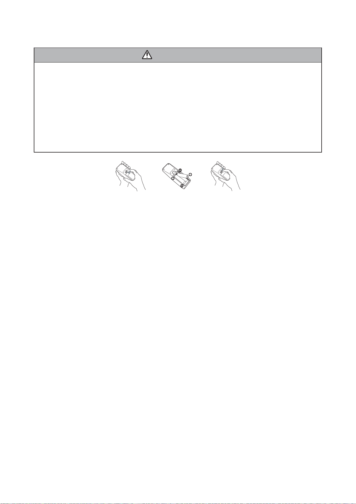
6-4 Putting batteries
WARNING
Always handle the batteries with care and use them only as directed. Improper use may result in battery
explosion, cracking or leakage, which could result in fire, injury and/or pollution of the surrounding environment.
• Be sure to use only the batteries specified. Do not use batteries of different types at the same time.
Do not mix a new battery with used one.
• Make sure the plus and minus terminals are correctly aligned when loading a battery.
• Keep a battery away from children and pets.
• Do not recharge, short circuit, solder or disassemble a battery.
• Do not allow a battery in a fire or water. Keep batteries in a dark, cool and dry place.
• If you observe a leakage of a battery, wipe out the flower and then replace a battery.
If the flower adheres your body or clothes, rinse well with water immediately.
• Use the batteries included in this product or two new batteries of the specified type: HITACHI MAXELL,
part number LR6 or R6P.
1. Remove the battery cover.
Slide back and remove the battery cover in the direction of the arrow.
2. Insert the batteries.
Align and insert the two AA batteries according to their plus and minus terminals as indicated in the
remote control.
3. Close the battery cover.
Replace the battery cover in the direction of the arrow and snap it back into place.
The signal settings for the remote control transmitter and the projector’s remote sensor can be changed.
If the remote control does not function properly try changing the signal setting.
Changing the signal setting for the remote control transmitter
(1) Setting 1 (FREQ. : NORMAL)
Simultaneously press and hold the VOLUME – and RESET buttons for about 3 seconds.
(2) Setting 2 (FREQ. : HIGH)
Simultaneously press and hold the MAGNIFY OFF and ESC buttons for about 3 seconds.
• Setting 1 is the factory default setting.
• When the batteries are removed from the remote control, user-specified settings are saved for about half a
day. If the batteries are removed from the remote control for longer than half a day, the remote will reset to
Setting 1.
Changing the signal setting for the projector’s remote sensor
Switch between Setting 1 and 2 using the SERVICE/REMOTE FREQ. item found in OPTION MENU.
Use the Ÿ/ź button to change the Projector's remote sensor setting.
1:NORMAL ļ 2:HIGH
Items with a checkmark are on. The factory default setting is for both 1:NORMAL and 2:HIGH to be on.
If the remote control does not function correctly set this to either only 1 or only 2. Neither can be turned off
at the same time.
NOTE: The remote control will not function properly if the remote control transmitter settings and the projec-
tor's remote sensor settings are not the same.
23
Page 24

ED-X31E / ED-X33E (C14B-20)
6-5 Air filter
WARNING
• Before caring, make sure the power switch is off and the power cable is not plugged in, then allow the
projector to cool suffi ciently. The care in a high temperature state of the projector could cause an electric
shock, a burn and/or malfunction to the projector.
• Use only the air fi lter of the specifi ed type. Do not use the projector with the air fi lter and the fi lter cover
removed. It could result in a fi re and/or malfunction to the projector.
• The air fi lter should be cleaned periodically. If the air fi lter becomes clogged by dust or the like, internal
temperatures rise and could cause a fi re, a burn and/or malfunction to the projector.
NOTE
• Please replace the air fi lter when it is damaged or too soiled, and also when you replace the lamp.
• Please reset the fi lter time only when you have cleaned or replaced the air fi lter, for a suitable indication
about the air fi lter.
• The projector may display the message such as “CHECK THE AIR FLOW” or turn itself off, to prevent the
internal heat level rising.
If the air fi lter becomes clogged by dust or the like, internal temperatures rise and could cause a fi re, a burn
and/or malfunction to the projector. When the indicators or a message prompts to clean the air fi lter, clean
the air fi lter as soon as possible.
Please check and clean the air fi lter periodically, even if there is no message.Please replace the air fi lter
when it is damaged or too soiled.
And also when you replace the lamp, please replace the air filter. An air filter of specified type will come
together with a replacement lamp for this projector.
1. Turn the projector off, and unplug the power cord. Allow the lamp to cool
for at least 45 minutes.
2. When the projector is suspended from the ceiling, apply the vacuum cleaner
to and around the fi lter cover fi rst, to prevent penetration of dust or the like.
3. Pull the filter cover knobs while lifting it. The filter unit which consists of the
filter' cover, air fi lter and fi lter frame will come off.
4. Use a vacuum cleaner for the fi lter vent of the projector and the fi lter frame
side of the fi lter unit.
If the air fi lter is damaged or too soiled, replace it according to the following
procedure number 5 to 7.
Otherwise, please jump to the procedure number 8.
5. Pull the fi lter frame' knob up while holding the fi lter cover. The fi lter frame will
come off and the air fi lter will appear.
6. Replace the air filter with new one.
7. Put the filter frame back.
8. Put the filter unit back into the projector.
9. Turn the projector on and reset the fi lter time using the FILTER TIME item in
the EASY MENU.
(1) Press the MENU button to display a menu.
(2) Point at the “FILTER TIME” using the ź/Ÿ button, then press the Ź button.
A dialog will appear.
(3) Press the Ÿ button to select “RESET” on the dialog. It performs resetting
the fi lter time.
Filter cover
Filter cover knobs
Filter unit
Filter frame
Filter (fi ner meshed)
Filter (larger meshed)
Filter cover
24
Page 25

6-6 Lamp
ED-X31E / ED-X33E (C14B-20)
WARNING
HIGH VOLTAGE HIGH TEMPERATURE HIGH PRESSURE
Ɣ
The projector uses a high-pressure mercury glass lamp. The lamp can break with a loud bang, or burn
out, if jolted or scratched, handled while hot, or worn over time. Note that each lamp has a different life-
time, and some may burst or burn out soon after you start using them. In addition, when the bulb bursts, it
is possible for shards of glass to fly into the lamp housing, and for gas containing mercury to escape
from the projector’s vent holes.
Ɣ
About disposal of a lamp • This product contains a mercury lamp; do not put it in the trash. Dispose of
in accord with environmental laws.
For lamp recycling, go to www.lamprecycle.org. (in the US) For product disposal, contact your local government agency or www.eiae.org (in the US) or www.epsc.ca (in Canada).
• If the lamp should break (it will make a loud bang when it does), unplug the power cord from
the outlet. Note that shards of glass could damage the projector’s internals, or cause injury
during handling.
Disconnect
the plug
from the
power
outlet
• If the lamp should break (it will make a loud bang when it does), ventilate the room well, and
make sure not to breathe the gas that comes out of the projector vents, or get it in your eyes
or mouth.
• Before replacing the lamp, turn the projector off and unplug the power cord, then wait at least
45 minutes for the lamp to cool suffi ciently. Handling the lamp while hot can cause burns, as
well as damaging the lamp.
• Never unscrew except the appointed (marked by an arrow) screws.
• Do not open the lamp cover while the projector is suspended from above. This is dangerous,
since if the lamp’s bulb has broken, the shards will fall out when the cover is opened.
• Do not use the projector with the lamp cover removed. At the lamp replacing, make sure that
the screws are screwed in fi rmly. Loose screws could result in damage or injury.
• Use only the lamp of the specifi ed type.
• If the lamp breaks soon after the fi rst time it is used, it is possible that there are electrical
problems elsewhere besides the lamp. If this happens, contact your local dealer or a service
representative.
• Handle with care: jolting or scratching could cause the lamp bulb to burst during use.
• Using the lamp for long periods of time could cause it dark, not to light up or to burst. When
the pictures appear dark, or when the color tone is poor, please replace the lamp as soon as
possible. Do not use old (used) lamps; this is a cause of breakage.
• Do not break up the lamp to replace because the structual parts broken up is unavailable.
25
Page 26

ED-X31E / ED-X33E (C14B-20)
Replacing the Lamp
A lamp has a fi nite product life. Using the lamp for long periods of time could cause the pictures darker or
the color tone poor. Note that each lamp has a different lifetime, and some may burst or burn out soon after
being started using.
1. Turn the projector off, and unplug the power cord. Allow the projector to
cool for at least 45 minutes.
2. Prepare a new lamp.
3. Loosen the screw (marked by arrow) of the lamp cover and then slide the
lamp cover to the side to remove it.
4. Loosen the 2 screws (marked by arrow) of the lamp, and slowly pick up
the lamp by the handles.
5. Insert the new lamp, and retighten firmly the 2 screws of the lamp that are
loosened in the previous process to lock it in place.
6. Slide the lamp cover back in place and firmly fasten the screw of the lamp
cover.
7. Turn the projector on and reset the lamp time using the LAMP TIME
function in the OPTION menu.
(1) Press the MENU button to display a menu. Only when the EASY MENU
has appeared, please perform the next step (2).
(2) Point at the “Go to Advanced Menu …” in the menu using ź/Ÿ button,
then press the Ź button.
(3) Point at the “OPTION” in the left column of the menu using ź/Ÿ button,
then press the Ź button.
(4) Point at the ”LAMP TIME” using ź/Ÿ button, then press the Ź button. A
dialog will appear.
(5) Press the Ÿ button to select “RESET” on the dialog. It performs resetting
the lamp time.
The lamp cover
Handles
NOTE
• Please reset the lamp time only when you have replaced the lamp, for a suitable indication about the lamp.
26
Page 27

ED-X31E / ED-X33E (C14B-20)
6-7 Other care
WARNING
Before caring, make sure the power switch is off and the power cable is not plugged in, and then allow the
projector to cool suffi ciently. The care in a high temperature state of the projector could cause a burn and/
or malfunction to the projector.
Avoid wetting the projector or inserting liquids in the projector. It could result in a fi re, an electric shock, and
and/or malfunction to the projector.
• Don’t put a container containing water , cleaner or chemicals near the projector.
• Don’t use aerosols or sprays.
CAUTION
Please take right care of the projector according to the following. Incorrect care could cause not only an
injury but adverse influence such as discoloration, peeling paint, etc.
• Do not use cleaner or chemicals other than those listed below.
• Do not polish or wipe with hard objects.
Inside of the projector
In order to ensure the safe use of the projector, it needs to clean and inspect the projector about once a year.
Caring for the lens
If the lens is flawed, soiled or fogged, it could cause deterioration of display quality. Please take care of the
lens, being cautions of the handling.
1. Turn the projector off, and unplug the power cord. Allow the projector to cool sufficiently.
2. After making sure that the projector is cool adequately, lightly wipe the lens with a commercially available
lens-cleaning wipe. Do not touch the lens directly with your hand.
Caring for the cabinet and remote control
Incorrect care could have adverse influence such as discoloration, peeling paint, etc.
1. Turn the projector off, and unplug the power cord. Allow the projector to cool sufficiently.
2. After making sure that the projector is cool adequately, lightly wipe with gauze or a soft cloth.
If soiling is severe, dip soft cloth in water or a neutral cleaner dilute in water, and wipe lightly after wringing
well. Then, wipe lightly with a soft, dry cloth.
27
Page 28

ED-X31E / ED-X33E (C14B-20)
6-8 Notice of AUTO adjustment
Use of AUTO adjustment with the image through RGB input optimizes V_POSI, H_POSI, and H_PHASE
automatically.
In case that projected image has dark tone around its peripheral, AUTO operation sometimes makes artifacts
in the image, shifts capture area and so on. Those failures are caused by period of image data is not exactly
distinguished to period of blanking on signal processing.
To avoid such phenomena, AUTO function should be used with the full size picture that has bright tone on its
peripheral.
Image when AUTO operates correctly
Note
1)
The phenomenon at the failure of AUTO adjustment depends on resolution of input source, scene of picture
etc.
2) There is no failure above in AUTO with video source through VIDEO, S-VIDEO or COMPONENT input.
The reason is why recognition of input signal’s standard does not need to search the capture range from input
signal itself.
Image when AUTO fails.
Noting image of top or bottom lines.
Shift of the image to East or West.
Artifacts on image. Etc.
28
Page 29

ED-X31E / ED-X33E (C14B-20)
6-9 How to deactivate the security functions
This projector is equipped with security functions.
(1)MyScreen PASSWORD
The MyScreen PASSWORD function can be used to prohibit access to the MyScreen function and prevent the currently registered MyScreen image from being overwritten.
(2)PIN LOCK
PIN LOCK is a function which prevents the projector from being used unless a registered Code is input.
(3)Transition detector
Transition detector is a function which prevents the projector from being used if vertical angle of the projector and mirror setting is not same with recorded.
64#05+6+10&'6'%61410
6JGRTQLGEVQTJCUDGGPVTCPUHGTTGF
HTQORTGXKQWUN[KPUVCNNGFRQUKVKQP
+H[QWYKUJVQJCXGCUSWCTGKOCIG
FKUCDNG6TCPUKVKQP&GVGEVQTQP/GPW
2+0$1:
QPUETGGPCICKP
Transition Detector
Alarm
(4)MY TEXT
This item allows you to display your own message (MY TEXT) on the START UP screen and INPUTINFORMATION. It can be protected by a password to prevent it from being overwritten.
It is possible to deactivate all security functions temporarily with following procedures.
(1) Go to “SECURITY” on OPTION Menu and press the Ź button.
Then, ENTER PASSWORD box will be displayed.
(The BOX will be displayed by pressing the [MENU] button (remote) or [Ÿ/ź/Ż/Ź] button (keypad) when
Transition Detector Alarm is displayed.)
5'%74+6;
'06'42#55914&
㪇㩷㩷㩷㪇㩷㩷㩷㪇㩷㩷㩷㪇
37+6 0':6
ENTER PASSWORD box
(2) Press the [Magnify off] button once, then press [Magnify off] button of remote for 3 second or more to dis-
play SERVICE PASSWORD box.
5'48+%'
'06'42#55914&
㪄㩷㩷㩷㪄㩷㩷㩷㪄㩷㩷㩷㪄
SERVICE PASSWORD box
(3) Enter the Life Key (MENU, ź, KEYSTONE, Ÿ). Then all security functions will be deactivated temporarily.
Note: • The Life key can be used up to 30 times. The key cannot be used thereafter. If the Life key cannot be
used, see the paragraph of SECURITY in the User’s Manual.
The frequency in which Life key is input will be set to 0 after the registered code is input.
•
The SECURITY Menu can not be operated if the SECURITY PASSWORD was released by Life key.
• The Mirror, Keystone and Auto keystone are not memorized though they are possible to operate if
Transition Detector was released by Life key.
• The MyScreen Lock on SCREEN Menu keeps “TURN ON” if MyScreen PASSWORD was set when
SECURITY PASSWORD was released by Life key.
29
Page 30

ED-X31E / ED-X33E (C14B-20)
6-10 PIN LOCK System
If the following PIN BOX menu appears after power on the projector, the PIN LOCK system has been activated. Under such a condition, key operations and signal displaying are inhibited. To open the PIN LOCK system, we need to input the correct 4 digits PIN CODE. If correct PIN CODE is not input in 5 min., the lamp will
be automatically turned off.
PIN BOX
Returning repaired unit
Use the Master PIN code. See the paragraph of Releasing the PIN LOCK system deactivation.
Swap unit/Returned unit
Release all security systems. See the paragraph of the PIN LOCK system deactivation.
Releasing the PIN LOCK System
When the PIN BOX menu is displayed, sequentially enter the codes with remote controller as follows. In
accordance with remote controller button entry,
“” mark appears in the PIN BOX menu.
Master PIN codes
1st entry code: Press the “MENU” button.
2nd entry code: Press the “ ” button.
3rd entry code: Press the “KEYSTONE” button.
4th entry code: Press the “ ” button.
Note: The Master PIN codes can be used up to 30 times. The codes cannot be used thereafter. If the Master
PIN codes cannot be used, see the paragraph of the PIN LOCK system deactivation.
The PIN LOCK System inactivation
1. When the PIN BOX menu is displayed, press “RESET” for 3 seconds or more in order to get the ID Inquiring Code.
PIN BOX
Inquiring Code
12 1234 1234
Inquiring Code
PIN BOX (ID Inquiring Code)
2. Send HITACHI sales company the Inquiring code (10 digits) to inquire the correct PIN code.
3. With the PIN BOX menu displayed, input the correct PIN code. Enter the correct PIN CODE that HITACHI
sales company supplied.
4. Open menu and select “TURN OFF” from the PIN LOCK items in the SECURITY menu. Then the PIN
BOX menu appears.
Password is required to display the Security Menu.
See the Security in OPTION menu: User’s Manual - Operating Guide.
5. Input the correct PIN code in the PIN BOX menu.
6. And then, PIN LOCK will be set to “TURN OFF”.
7.Deactivate the MyScreen PASSWORD and Transition Detector too.
Reset the Security Password to the [6971].
See the Security in OPTION menu: User’s Manual - Operating Guide.
30
Page 31

ED-X31E / ED-X33E (C14B-20)
6-11 Related Messages
When the unit’s power is on, messages such as those shown below may be displayed. When any such message
is displayed on the screen, please respond as described below.
Although these messages will be automatically disappeared around several minutes, it will be reappeared every
time the power is turned on.
Message Description
NO INPUT IS DETECTED
***
SYNC IS OUT OF RANGE
***
fH
*****kHz fV *****Hz
INVALID SCAN FREQ.
***
CHECK THE AIR FLOW
REMINDER
***HRS PASSED AFTER THE
LAST FILTER CHECK.
FILTER MAINTENANCE IS ESSENTIAL
TO REMOVE WARNING MESSAGE,
RESET FILTER TIMER.
SEE MANUAL FURTHER INFO.
There is no input signal.
Please confi rm the signal input connection, and the status of the signal source.
The horizontal or vertical frequency of the inputted signal is outside of the
response parameters of this unit.
Please confi rm the specs for this unit or the signal source specs.
An improper signal is input.
Please confi rm the specs for your projector or the signal source specs.
The internal portion temperature is rising.
Please turn the power OFF, and allow the unit to cool down at least 20 minutes.
After having confi rmed the following items, please turn the power ON again.
• Is there blockage of the air passage aperture?
• Is the air fi lter dirty?
• Does the peripheral temperature exceed 35°C?
If the same indication is displayed after the remedy, please set FAN SPEED of the
SERVICE item in the OPTION menu to HIGH.
A note of precaution when cleaning the air fi lter.
Please immediately turn the power OFF, and clean or change the air filter by
referring to the “Air Filter” section of this manual. After you have cleaned or
changed the air fi lter, please be sure to reset the fi lter timer.
31
Page 32

ED-X31E / ED-X33E (C14B-20)
6-12 Regarding the indicator lamps
Lighting and flashing of the POWER indicator, the LAMP indicator, and the TEMP indicator have the meanings
as described in the table below. Please respond in accordance with the instructions within the table.
POWER
indicator
Lighting
In Orange
Blinking
In Green
Lighting
In Green
Blinking
In Orange
Blinking
In Red
Blinking
In Red
or
Lighting
In Red
Blinking
In Red
or
Lighting
In Red
Blinking
In Red
or
Lighting
In Red
Blinking
In Red
or
Lighting
In Red
Lighting
In Green
Lighting
In Green
LAMP
indicator
Turned
off
Turned
off
Turned
off
Turned
off
(discretionary)
Lighting
In Red
Blinking
In Red
Turned
off
Turned
off
Alternative
blinking in Red
Simultaneous
blinking in Red
TEMP
indicator
Turned
off
Turned
off
Turned
off
Turned
off
(discretionary)
Turned
off
Turned
off
Blinking
In Red
Lighting
In Red
Description
The projector is in a standby state.
The projector is warming up.
Please wait.
The projector is in an on state.
Ordinary operations may be performed.
The projector is cooling down.
Please wait.
The projector is cooling down. A certain error has been detected.
Please wait until the POWER indicator fi nishes blinking, and then perform the proper
measure using the item descriptions below.
The lamp does not light, and there is a possibility that interior portion has
become heated.
Please turn the power off, and allow the projector to cool down at least 20 minutes.
After the projector has suffi ciently cooled down, please make confi rmation of the
following items, and then turn the power on again.
• Is there blockage of the air passage aperture?
• Is the air fi lter dirty?
• Does the peripheral temperature exceed 35ºC?
If the same indication is displayed after the remedy, please change the lamp referring
to the section “Lamp”.
The lamp cover has not been properly fi xed (attached).
Please turn the power off, and allow the unit to cool down at least 45 minutes. After
the projector has suffi ciently cooled down, please make confi rmation of the attachment
state of the lamp cover. After performing any needed maintenance, turn the power on
again.
The cooling fan is not operating.
Please turn the power off, and allow the unit to cool down at least 20 minutes. After
the projector has suffi ciently cooled down, please make confi rmation that no foreign
matter has become caught in the fan, etc., and then turn the power on again.
If the same indication is displayed after the remedy, please replace a fan.
There is a possibility that the interior portion has become heated.
Please turn the power off, and allow the unit to cool down at least 20 minutes. After
the projector has suffi ciently cooled down, please make confi rmation of the following
items, and then turn the power on again.
• Is there blockage of the air passage aperture?
• Is the air fi lter dirty?
• Does the peripheral temperature exceed 35°C?
If the same indication is displayed after the remedy, please set the FAN SPEED of the
SERVICE item in the OPTION menu to HIGH.
There is a possibility that the interior portion has become overcooled.
Please use the unit within the usage temperature parameters (5°C to 35°C). After
the treatment, resent the power to ON. If the same indication is displayed after
the treatment, please make sure that the proper cables are connected to each of
connectors E301, E302 and E304 on the PWB assembly MAIN.
It is time to clean the air fi lter.
Please immediately turn the power OFF, and clean or change the air fi lter referring to
the section “Air Filter”. After cleaning or change the air fi lter, please be sure to reset
the fi lter timer. After the remedy, resent the power to ON.
NOTE •
When the interior portion has become overheated, for safety purposes, the power source is automatically turned off, and the indicator lamps may also be turned off. In such a case, press the “ż” (OFF) side of the
power switch, and wait at least 45 minutes. After the projector has suffi ciently cooled down, please make confi rmation of the attachment state of the lamp and lamp cover, and then turn the power on again.
32
Page 33

ED-X31E / ED-X33E (C14B-20)
6-13 HIDDEN SERVICE MENU
To display the OSD for “HIDDEN SERVICE MENU” set up.
HIDDEN SERVICE
AIR-SENSOR
LAMP ALARM
STARTUP TYPE
PANEL TIME
LONG KEY
SOFT RESET
EXECUTE
NONE
1
1234h
TURN OFF
1. Display the Advanced menu by
By the control panel By the remote control transmitter
the “MENU” button.(If EASY
MENU appears, choose “Go to
Advanced menu” to display
ADVANCED MENU.)
2. Select the “OPTION” on the
menu.
3. Continue press the button [
fi rst, then press the button [ ]
together with “INPUT”, and hold
for 3 seconds.
AIR - SENSOR
Execute this item to adjust the air sensor.
LAMP ALARM
Select the lamp alarm level. 3 Level ļ 1 Level ļ None
STARTUP TYPE
Select the startup screen type. 1 : shows Hitachi Logo
2 : No Hitachi Logo
1. Display the menu by the
“MENU” button. (If EASY
MENU appears, choose “Go to
Advanced menu” to display
ADVANCED MENU.)
2. Select the “OPTION” on the menu.
3. Press the “MAGNIFY OFF”
]
button.
Next hold the “MAGNIFY OFF”
button for 3 seconds.
PANEL TIME
Use time of LCD panel. Reset the PANEL TIME whenever you changed the LCD/LENS prism assembly panel.
LONG KEY
Projector react only to the key pressing the remote button for 3 seconds. Turn off ļ Turn on.
When LONG KEY mode is on, MY BUTTON1 behave as “LONG KEY DISABLE” and MY BUTTON2 behave
as “LONG KEY ENABLE”.
SOFT RESET
If this is executed, all of the user data is initialized.Never use it when not required.
6-14 RUN TIME window
Set operating time display method (accumulated lamp time display method)
1. Select “OPTION” from the Advanced menu, then place the cursor on the “LAMP TIME”.
2. Press the [ ], [ENTER] or [RESET] button.
3. Press the [Reset] button once, then press [KEYSTONE] button of the remote control for 3 seconds or
more to display the screen shown below. (The menu will close after 10 seconds if there are no further
operations.)
4. Use [ ] or [ ] to select the usage status number. (The usage status is as shown below.)
RUN TIME
LAMP Lamp time1234h
NORMAL Lamp time(Normal)1000
WHISPER Lamp time(Whisper)234
AC 2000 AC energizing time
On Number of times on1
Off Number of times off
h
h
h
0
No.0 Usage status number(See below)
Usage status number
0 ..... Total usage status
1 ..... Current usage status
2 ..... Usage status before first reset
3 ..... Usage status before second reset
9 ..... Usage status before eighth reset
||
33
Page 34

7. Wiring diagram
Wiring of the circuit power unit
(1) Attach the CNGD1 and the CNGD3 with screw.
(2) Connect the TSW after you confirmed the print of the TSW.
(3) Connect the CNPW.
(4) Bundle the CNPW and the TSW with purse lock (PAS1).
Make sure not to touch with adjustment
VR in the power unit board.
Never stress the standing board.
45°
34
Touch the CNGD1 to the rotation stop rib,
then attach the CNGD1 with screw.
Circuit power unit
Use black silk (printed on board)
circuit power unit.
Area of Importance
Area of Importance
The operations with this symbol have implications
with laws/standards. It is possible to be in violation
of these laws/standards in the case that these operations
are not carried out according to the instructions.
Assemble according to the operation instructions.
CNGD1
ED-X31E / ED-X33E (C14B-20)
CNGD3
Make sure to confirm the print of the TSW.
Area of Importance
[YS11A75A-**] (75°C)
Make sure to connect the TSW and the CNPW.
You can not confirm the connection at the later process.
TSW
CNPW
30±10mm
PAS1
Wiring diagram 1
Page 35

Preparation of the ballast power unit
(1) Connect the CNBAR, the CNPFC and the CNLAP.
Wiring after attaching the ballast power unit
(1) Style the CNBAR, the CNPFC and the CNLAP.
(2) Use Ballast power unit white or white marked CNPFC connector is mounted.
(3) Pass CNPFC lead through FEB2, and lock hook completely.
Area of Importance
(4) Pass CNLAP lead through FEB4, and lock hook completely.
CNBAR
Area of Importance
Pass the CNBAR through ballast holder hole.
Never make the excessive length between the
ballast power unit and ballast holder.
Area of Importance
ED-X31E / ED-X33E (C14B-20)
FEB4
Number of pins are same with the CNPFC and the CNLAP.
Never insert the wrong connectors.
Ballast power unit
CNBAR
Ballast sheet
35
Make sure to lock the CNLAP completely.
You can not confirm the connection at the
later process.
Attach FEB4 (Ferrite core) to CNLAP.
Make sure to lock hook completely.
Do not pinch cables by hook.
CNLAP
Area of Importance
Make sure to lock the CNPFC completely.
You can not confirm the connection at the
later process.
FEB2
Attach FEB2 (Ferrite core) to CNPFC.
Make sure to lock hook completely.
Do not pinch cables by hook.
CNPFC
Ballast power unit
Area of Importance
Wiring diagram 2
FEB4
CNLAP
Ballast holder
CNPFC
FEB2
Page 36

Assembling of the power unit block
The assembly order of the power block
Assemble the circuit power unit and ballast power unit
(Ballast holder) by the following procedures.
Refer the wiring of the power unit block (Next page) to
style the cables, after you assembled the power unit block.
1. Connection of the circuit power unit and the ballast power unit,
Preparation for assembling.
(1) Connect the CNPFC to the circuit power unit.
(2) Pass the CNGD1 and the TSW through the ballast holder hole.
Ballast holder
CNGD1
2. Assembling of the circuit power unit and ballast power unit.
(1) Attach the ballast holder to the circuit power unit drawing out the CNPW.
Assemble the ballast holder and the circuit power unit touching the CNPW to
the arrow A side wall of the ballast holder.
You can easily draw out the CNPW.
(2) Draw out the CNPW from the ballast holder hole, then style the CNGD1 and the TSW.
Do not make the excessive length in the power unit.
Do not pull the CNGD1 and the TSW strongly, otherwise connector might be released.
(3) Style the igniter lead (CNLAP) on the ballast sheet.
Make sure not to release the CNLAP from ballast holder hook, then attach the ballast
holder with screws.
CNGD1
Do not make the excessive length in the power unit.
Do not pull the CNGD1 and the TSW strongly.
ED-X31E / ED-X33E (C14B-20)
TSWCNGD3
CNPW
CNPW
36
TSW
Ballast power unit
Ballast sheet
CNPFC
< Wiring of CNLAP and CNGD3 >
FEB4
Make sure not to release
the CNLAP from ballast
holder hook.
FEB2
Circuit power unit
Ballast holder
CNLAP
CNGD3
CNGD3
Ballast holder
Ballast power unit
Never incline the board.
CNPFC
FEB2
Assemble the ballast holder touching the CNPW
to the arrow A side wall of the ballast holder.
You can easily draw out the CNPW from ballast
holder hole.
Arrow A
CNPW
Circuit power unit
Wiring diagram 3
Page 37

Wiring of the power unit
Style of the power unit assembling
(1) Style CNBAR to ballast holder rib, and fix with ZTP2.
(2) Attach the CNDG1 to a ballast holder boss.
• Make sure not to overflow the lead from ballast holder slit. (Otherwise, upper case will pinch the lead.)
• Do not make excessive length at the power unit side.
(3) Attach the CNGD3 to a ballast holder boss.
• Make sure not to overflow the lead from ballast holder slit. (Otherwise, lamp case and ballast holder will pinch the lead.)
• Do not make excessive length at the power unit side.
(4) Combine CNGD3 and CNGD1, and fix with ZTP6.
Make sure not to overflow the lead from ballast
holder slit.
Otherwise, lamp case and upper case will pinch
the lead.
< OK >
CNGD3 lead
37
Make sure not to overflow the lead
from ballast holder slit.
Otherwise,upper case will pinch
the lead.
< OK >
CNGD1 lead CNGD1 lead
< NG >
CNGD3 lead
< NG >
Put CNGD3 under CNGD1.
Do not make excessive length of
CNGD1 and CNGD3.
Attach them to power unit box with
tape.
ZTP6
ZTP2
CNGD3
TSW
CNPW
CNBAR
Style CNBAR to ballast holder rib.
Attach CNBAR to power unit box with tape.
Never make the excessive at the ballast power unit side.
ED-X31E / ED-X33E (C14B-20)
Area of Importance
Otherwise, the CNBAR lead will touch to the primary of
the power unit.
CNGD1
Wiring diagram 4
Page 38

Preparation of the main board assembling
Wiring of the input board assembling
(1) Connect Main board and Input board with CNVID and CNAU.
Refer to following procedure.
Insert to main board connector.
Insert to Input board connector.
Attach Input board to I/O metal.
I/O metal
ED-X31E / ED-X33E (C14B-20)
38
Input board
CNAU
Main board
CNVID
Wiring diagram 5
Page 39

Preparation of the panel duct
(1) Draw out the E1 from the panel duct incision.
Style the E1 along the side of panel duct, then fix the E1 with tape.
Wiring of the panel duct assembling
(2) Attach the E2 to the panel duct with screw, then draw out the E2 from panel duct slit.
Make sure not make the excessive length in the panel duct.
Draw out the E2 from panel duct slit.
Make sure not make the excessive length in the
panel duct.
ED-X31E / ED-X33E (C14B-20)
E2
39
ZTP
Draw out the E1 from panel duct slit.
Make sure not make the excessive between the slit and the tape.
Wiring diagram 6
Panel duct
E1
Page 40

Attaching the power unit
Wiring of the power unit attaching
(1) Attach the CNGD2. (Attach the lamp house with this screw too.)
(2) Pass the power fan and the CNBAR through the ballast holder slit.
Make sure not make the excessive length at the fan side.
(3) Attach the CNLAP to the lamp holder (bottom case). Make sure not to damage the lead.
(4) Pass the RG panel fan and the E1 through the panel duct slit. Attach them to the panel duct.
(5) Connect the CNRM to the remote board. Then attach the remote board to the bottom case.
(6) Pass the CNRM through the lead holder of panel duct.
(7) Pass CNBAR through power unit lead holder. Then, Attach power unit lead holder to ballast holder.
40
Pass CNRM through the lead holder
of panel duct.
CNRM
B
Panel
fan
Pass the RG panel fan and the E1
through the panel duct slit.
E1
RG
Panel
fan
Lamp
fan
remote board
Power
E2
fan
CNBAR
Pass power fan lead through ballast
holder slit.
Pass CNBAR through power unit lead holder.
Attach CNBAR to box with tape.
Confirm that tape does not peel off.
Confirm that tape does not peel off.
ED-X31E / ED-X33E (C14B-20)
Power unit lead holder
Make sure not to damage the CNLAP (igniter lead)
by lamp house when you attach the CNLAP.
Make sure not to put the CNLAP on the step of the
bottom case.
Otherwise, it suffers stress to the connector.
(See the below figure)
To ballast
OK
CNLAP
CNGD3
CNGD2
CNLAP
bottom case
NG
The connector is put on
the step, the connector is
being suffered the stress.
CNGD1
TSW CNPW
exhaust
fan
Wiring diagram 7
Page 41

Attaching the optics unit
Wiring of the optics unit attaching
(1) Pass the CNGD2 between the optics unit attaching boss and the main board attaching boss.
Then, attach the optics unit.
(2) Style the E1, RG panel fan and lamp fan at the internal than main board attaching boss.
Power
E2 CNBAR
fan
CNRM
B
panel
fan
41
Style the E1, RG panel fan and lamp fan
at the internal than main board attaching
boss.
Style the lamp fan between the optics
unit and panel duct.
E1
RG
panel
fan
lamp
fan
CNGD2
Pass the CNGD2 between the optics unit attaching boss and
the main board attaching boss. Then, attach the optics unit.
Make sure not to pinch the CNGD2.
You have to attach the CNGD2 with screw after you attached
the main board. So, draw out the CNGD2 to the power unit
side first.
CNGD3
exhaust
CNPWCNGD1 TSW
fan
ED-X31E / ED-X33E (C14B-20)
Wiring diagram 8
Page 42

Attaching the main board
(1) Attach main board after you connected exhaust fan. Attach main board with CNGD2 and CNGD3 by screw. Put CNGD2 under CNGD3.
(2) Connect CNPW. Put TSW and CNGD1 under CNPW.
(3) Connect RG panel fan, B panel fan, lamp fan, E1, E2 and CNRM.
Wiring of the main board attaching
Put excessive length of each cables into the space between B panel fan and panel duct.
Otherwise, upper case will pinch cables.
(4) Cross CNBAR and power fan. Then, connect to main board. Otherwise, upper case will pinch cables. Touch power fan lead to ballast holder shield and attach with tape.
(5) Connect flexible cables (LCD panel).
(6) Wrap TSW to CNGD1 5 times. Then, attach CNGD1 and TSW.
Area of Importance
(7) Attach speaker after you styled cables.
Confirm that CNBAR is passing through
power unit lead holder.
Cross power fan and CNBAR.
ZTP5
Put excessive length of RG panel fan,
B panel fan, lamp fan, E1 and E2 into the
space between B panel fan and panel duct.
E2
42
E1 and E2 are same connector.
So, insert two connectors correctly.
<Inserted in correctly>
Temparature error will occur.
TEMP-LED will light.
CNRM
Power
fan
CNGD3
Confirm that tape does not peel off.
Area of Importance
Touch power unit fan lead to ballast holder,
and attach with tape.
Confirm that CNGD1 and CNGD3 are fixed by
ballast holder ribs.
Confirm that there is no excessive length between
rib and power unit.
ED-X31E / ED-X33E (C14B-20)
Panel
Panel
You do not have to style the lamp fan.
Make sure not to touch the speaker
corn during your work.
RG
fan
B
fan
B panel
E1
lamp
fan
G panel
A83
R panel
CNBAR
Main board
CNPW
exhaust
fan
CNGD1
CNGD2
TSW
Attach CNGD2 and CNGD3 to main board with screw
before you connect CNPW, TSW and CNGD1 to main board.
Put CNGD2 under CNGD3. Keep CNGD2 horizontal as drawn
in diagram.
Keep CNGD3 horizontal as much as possible.
Otherwise, you can not draw out CNPW.
Wrap the TSW to the CNGD1 5 times or more. Then attach the
CNGD1 with screw and attach the TSW.
Area of Importance
Never put the TSW lead near the lamp side.
Otherwise, TSW lead will be pinched by upper case.
Wiring diagram 9
Page 43

ED-X31E / ED-X33E (C14B-20)
8. Disassembly diagram
PWB assembly
INPUT
23
10
10
19
M4x6
obverse
6
reverse
rear
T3x10M3x8
22
43
Page 44

ED-X31E / ED-X33E (C14B-20)
44
Page 45

ED-X31E / ED-X33E (C14B-20)
Notice
1. Detach and attach the upper case.
Follow the procedure below to detach and attach the upper case.
When disassembling
a. Remove the Lamp door.
CAUTION
The lamp door must be removed before the upper case when disassembling the machine. If the upper
case is detached with the lamp door installed, the MAIN board might be damaged.
Lamp door
Loosen this screw
b. Remove 7 screws on the bottom and 3 screws on the rear to detach the upper case.
CAUTION
These are not screw holes. Do NOT insert a screw or screwdriver into them to avoid damaging the inside.
2 screws
7 screws
45
Page 46

ED-X31E / ED-X33E (C14B-20)
When assembling
a. Tighten 7 screws on the bottom and 2 screws on the rear after attaching the upper case with the lamp
door separated.
CAUTION
These are not screw holes. Do NOT insert a
screw or screwdriver into them to avoid damaging the inside.
In order not to make a gap between the upper and the bottom cases, tighten these screws while pressing
down the upper case in the direction of the arrow. Be careful not to bend the outside casing.(Torque:0.39-
0.59N•m)
b. Attach the Lamp door.
Lamp door
CAUTION
Tighten this screw using a manual screwdriver.
46
Page 47

ED-X31E / ED-X33E (C14B-20)
2. Detaching and attaching the Panel Fan Duct assembly
When disassembling
Remove 1 screws and unhook the panel fan duct assembly as shown in the diagram.
[above]
Release the 5 hooks
T3x12
When assembling
(1) Put the thermistor and Air sensor in the correct position on the Panel duct as shown in the diagram.
3. Attaching the dichroic optics unit
Put the dichroic optics unit on the bottom case, and tighten screws
in order of 1, 2, 3 and 4 as shown in the diagram.
47
Page 48

ED-X31E / ED-X33E (C14B-20)
4. Attaching the power unit FAN.
Never attach the FAN to the wrong direction.
Refer the stamp on the FAN when you attach the power unit FAN.
5. Attaching the exhaust FAN.
Never attach the FAN to the wrong direction.
Refer the diagram when you attach the exhaust FAN.
Stamp is reverse side.
48
Page 49

ED-X31E / ED-X33E (C14B-20)
6. Attaching the power unit.
Refer the diagram when you attach the power unit.
Pull the AC inlet frame to the outside.
Then, attach the power unit.
Make sure that the bottom case does
not come in contact with AC SW.
CAUTION
Never use the wrong screws.
M3 x 6 with lock washer.
49
Page 50

ED-X31E / ED-X33E (C14B-20)
7. Attaching the Lens prism ASSY.
Refer the diagram when you attach the Lens prism ASSY.
(2) Attach the LCD prism ASSY inserting the
top of the Lens to the lens enclosure.
Never touch the LCD to any parts when you
attach the LCD prism ASSY.
Insert vertically to the positioning boss.
50
Page 51

ED-X31E / ED-X33E (C14B-20)
9. Replacement Parts list
THE UPDATED PARTS LIST
FOR THIS MODEL IS
AVAILABLE ON ESTA
VIDEO
ASPECT SEARCH
MAGNIFY
ON
Power Cord RGB Cable
or
Instruction manual
OFF
KEYSTONE
POSITION
ESC
Remote ControlAudio/Video cable
COMPUTER
AUTO
FREEZE
MY BUTTON
MY SOURCE/
DOC.CAMERA
PAGE
UP
DOWN
12
ENTER
R007
BLANK
VOLUME
㧗
MUTE
MENU
RESET
Lens cover and strap
51
Page 52

ED-X31E / ED-X33E (C14B-20)
5. RS-232C communication
1234
6
CONTROL port RS-232C cable (cross) RS-232C port
of the projector of the computer
RD (2) (2) RD
TD (3) (3) TD
- (4) (4) DTR
GND (5) (5) GND
- (6) (6) DSR
RTS (7) (7) RTS
CTS (8) (8) DTS
- (9) (9) RI
5
789
- (1) (1) CD
12345
6
789
Connecting the cable
Turn off the projector and the computer.
1.
Connect the CONTROL port of the projector with a RS-232C port of
2.
the computer by a RS-232C cable (cross). Use the cable that fulfi lls the
specifi cation shown in the previous page.
Turn the computer on, and after the computer has started up turn the projector
3.
on.
Communications setting
19200bps, 8N1
1. Protocol
Consist of header (7 bytes) + command data (6 bytes)
2. Header
BE + EF + 03 + 06 + 00 + CRC_low + CRC_high
CRC_low: Lower byte of CRC fl ag for command data
CRC_high: Upper byte of CRC fl ag for command data
3. Command data
Command data chart
byte_0 byte_1 byte_2 byte_3 byte_4 byte_5
Action Type Setting code
low high low high low high
Action (byte_0 - 1)
Action Classifi cation Content
1 Set Change setting to desired value.
2 Get Read projector internal setup value.
4 Increment Increment setup value by 1.
5 Decrement Decrement setup value by 1.
6 Execute Run a command.
52
Page 53

ED-X31E / ED-X33E (C14B-20)
Requesting projector status (Get command)
(1) Send the following request code from the PC to the projector.
Header + Command data (‘02H’ + ‘00H’ + type (2 bytes) + ‘00H’ + ‘00H’)
(2) The projector returns the response code ‘1DH’ + data (2 bytes) to the PC.
Changing the projector settings (Set command)
(1) Send the following setting code from the PC to the projector.
Header + Command data (‘01H’ + ‘00H’ + type (2 bytes) + setting code (2 bytes))
(2) The projector changes the setting based on the above setting code.
(3) The projector returns the response code ‘06H’ to the PC.
Using the projector default settings (Reset Command)
(1) The PC sends the following default setting code to the projector.
Header + Command data (‘06H’ + ‘00H’ + type (2 bytes) + ‘00H’ + ‘00H’)
(2) The projector changes the specifi ed setting to the default value.
(3) The projector returns the response code ‘06H’ to the PC.
Increasing the projector setting value (Increment command)
(1) The PC sends the following increment code to the projector.
Header + Command data (‘04H’ + ‘00H’ + type (2 bytes) + ‘00H’ + ‘00H’)
(2) The projector increases the setting value on the above setting code.
(3) The projector returns the response code ‘06H’ to the PC.
Decreasing the projector setting value (Decrement command)
(1) The PC sends the following decrement code to the projector.
Header + Command data (‘05H’ + ‘00H’ + type (2 bytes) + ‘00H’ + ‘00H’)
(2) The projector decreases the setting value on the above setting code.
(3) The projector returns the response code ‘06H’ to the PC.
When the projector cannot understand the received command
When the projector cannot understand the received command, the error code ‘15H’
is sent back to the PC.
Sometimes the projector cannot properly receive the command. In such a case, the
command is not executed and the error code ‘15H’ is sent back to the PC. If this
error code is returned, send the same command again.
When the projector cannot execute the received command.
When the projector cannot execute the received command, the error code ‘1CH’ +
‘xxxxH’ is sent back to the PC.
When the data length is greater than indicated by the data length code, the
projector ignore the excess data code. Conversely when the data length is shorter
than indicated by the data length code, an error code will be returned to the PC.
NOTE • Operation cannot be guaranteed when the projector receives an undefi ned
command or data.
• Provide an interval of at least 40ms between the response code and any other code.
• The projector outputs test data when the power supply is switched ON, and when the
lamp is lit. Ignore this data.
• Commands are not accepted during warm-up.
53
Page 54

ED-X31E / ED-X33E (C14B-20)
Names Operation Type Header
Power
Input Source
Error Status
BRIGHTNESS
BRIGHTNESS Reset
CONTRAST
CONTRAST Reset
PICTURE MODE
GAMMA
Set Turn off BE EF 03 06 00 2A D3 01 00 00 60 00 00
Turn on BE EF 03 06 00 BA D2 01 00 00 60 01 00
Get BE EF 03 06 00 19 D3 02 00 00 60 00 00
[Example return]
00 00 01 00 02 00
[Off] [On] [Cool down]
Set COMPUTER1 BE EF 03 06 00 FE D2 01 00 00 20 00 00
COMPUTER2 BE EF 03 06 00 3E D0 01 00 00 20 04 00
COMPONENT BE EF 03 06 00 AE D1 01 00 00 20 05 00
S-VIDEO BE EF 03 06 00 9E D3 01 00 00 20 02 00
VIDEO BE EF 03 06 00 6E D3 01 00 00 20 01 00
Get BE EF 03 06 00 CD D2 02 00 00 20 00 00
Get BE EF 03 06 00 D9 D8 02 00 20 60 00 00
[Example return]
00 00 01 00 02 00 03 00
[Normal] [Cover error] [Fan error] [Lamp error]
04 00 05 00 06 00 07 00
[Temp error] [Air fl ow error] [Lamp time error] [Cold error]
08 00 09 00 10 00
[Filter error] (Filter missing error) (Inner Sencer error)
Get BE EF 03 06 00 89 D2 02 00 03 20 00 00
Increment BE EF 03 06 00 EF D2 04 00 03 20 00 00
Decrement BE EF 03 06 00 3E D3 05 00 03 20 00 00
Execute BE EF 03 06 00 58 D3 06 00 00 70 00 00
Get BE EF 03 06 00 FD D3 02 00 04 20 00 00
Increment BE EF 03 06 00 9B D3 04 00 04 20 00 00
Decrement BE EF 03 06 00 4A D2 05 00 04 20 00 00
Execute BE EF 03 06 00 A4 D2 06 00 01 70 00 00
Set NORMAL BE EF 03 06 00 23 F6 01 00 BA 30 00 00
CINEMA BE EF 03 06 00 B3 F7 01 00 BA 30 01 00
DYNAMIC BE EF 03 06 00 E3 F4 01 00 BA 30 04 00
BOARD(BLACK) BE EF 03 06 00 E3 EF 01 00 BA 30 20 00
BOARD(GREEN) BE EF 03 06 00 73 EE 01 00 BA 30 21 00
WHITEBOARD BE EF 03 06 00 83 EE 01 00 BA 30 22 00
DAYTIME BE EF 03 06 00 E3 C7 01 00 BA 30 40 00
Get BE EF 03 06 00 10 F6 02 00 BA 30 00 00
[Example return]
00 00 01 00 04 00 10 00
[Normal] [Cinema] [Dynamic] [Custom]
20 00 21 00 22 00 40 00
[BOARD(BLACK) ] [BOARD(GREEN) ] [WHITEBOARD] [DAY TIME]
Set #1 DEFAULT BE EF 03 06 00 07 E9 01 00 A1 30 20 00
#1 CUSTOM BE EF 03 06 00 07 FD 01 00 A1 30 10 00
#2 DEFAULT BE EF 03 06 00 97 E8 01 00 A1 30 21 00
#2 CUSTOM BE EF 03 06 00 97 FC 01 00 A1 30 11 00
#3 DEFAULT BE EF 03 06 00 67 E8 01 00 A1 30 22 00
#3 CUSTOM BE EF 03 06 00 67 FC 01 00 A1 30 12 00
#4 DEFAULT BE EF 03 06 00 F7 E9 01 00 A1 30 23 00
#4 CUSTOM BE EF 03 06 00 F7 FD 01 00 A1 30 13 00
#5 DEFAULT BE EF 03 06 00 C7 EB 01 00 A1 30 24 00
#5 CUSTOM BE EF 03 06 00 C7 FF 01 00 A1 30 14 00
#6 DEFAULT BE EF 03 06 00 57 EA 01 00 A1 30 25 00
#6 CUSTOM BE EF 03 06 00 57 FE 01 00 A1 30 15 00
Get BE EF 03 06 00 F4 F0 02 00 A1 30 00 00
Command Data
CRC Action Type Setting Code
54
Page 55

ED-X31E / ED-X33E (C14B-20)
Names Operation Type Header
User Gamma Pattern Set Off BE EF 03 06 00 FB FA 01 00 80 30 00 00
9 steps gray scale BE EF 03 06 00 6B FB 01 00 80 30 01 00
15 steps gray scale BE EF 03 06 00 9B FB 01 00 80 30 02 00
Ramp BE EF 03 06 00 0B FA 01 00 80 30 03 00
Get BE EF 03 06 00 C8 FA 02 00 80 30 00 00
User Gamma Point 1 Get BE EF 03 06 00 08 FE 02 00 90 30 00 00
Increment BE EF 03 06 00 6E FE 04 00 90 30 00 00
Decrement BE EF 03 06 00 BF FF 05 00 90 30 00 00
User Gamma Point 2 Get BE EF 03 06 00 F4 FF 02 00 91 30 00 00
Increment BE EF 03 06 00 92 FF 04 00 91 30 00 00
Decrement BE EF 03 06 00 43 FE 05 00 91 30 00 00
User Gamma Point 3 Get BE EF 03 06 00 B0 FF 02 00 92 30 00 00
Increment BE EF 03 06 00 D6 FF 04 00 92 30 00 00
Decrement BE EF 03 06 00 07 FE 05 00 92 30 00 00
User Gamma Point 4 Get BE EF 03 06 00 4C FE 02 00 93 30 00 00
Increment BE EF 03 06 00 2A FE 04 00 93 30 00 00
Decrement BE EF 03 06 00 FB FF 05 00 93 30 00 00
User Gamma Point 5 Get BE EF 03 06 00 38 FF 02 00 94 30 00 00
Increment BE EF 03 06 00 5E FF 04 00 94 30 00 00
Decrement BE EF 03 06 00 8F FE 05 00 94 30 00 00
User Gamma Point 6 Get BE EF 03 06 00 C4 FE 02 00 95 30 00 00
Increment BE EF 03 06 00 A2 FE 04 00 95 30 00 00
Decrement BE EF 03 06 00 73 FF 05 00 95 30 00 00
User Gamma Point 7 Get BE EF 03 06 00 80 FE 02 00 96 30 00 00
Increment BE EF 03 06 00 E6 FE 04 00 96 30 00 00
Decrement BE EF 03 06 00 37 FF 05 00 96 30 00 00
User Gamma Point 8 Get BE EF 03 06 00 7C FF 02 00 97 30 00 00
Increment BE EF 03 06 00 1A FF 04 00 97 30 00 00
Decrement BE EF 03 06 00 CB FE 05 00 97 30 00 00
COLOR TEMP Set HIGH BE EF 03 06 00 0B F5 01 00 B0 30 03 00
CUSTOM-1 (HIGH) BE EF 03 06 00 CB F8 01 00 B0 30 13 00
MID BE EF 03 06 00 9B F4 01 00 B0 30 02 00
CUSTOM-2 (MID) BE EF 03 06 00 5B F9 01 00 B0 30 12 00
LOW BE EF 03 06 00 6B F4 01 00 B0 30 01 00
CUSTOM-3 (LOW) BE EF 03 06 00 AB F9 01 00 B0 30 11 00
Hi-BRIGHT-1 BE EF 03 06 00 3B F2 01 00 B0 30 08 00
CUSTOM-4 (Hi-BRIGHT-1)
Hi-BRIGHT-2 BE EF 03 06 00 AB F3 01 00 B0 30 09 00
CUSTOM-5 (Hi-BRIGHT-2)
Hi-BRIGHT-3 BE EF 03 06 00 5B F3 01 00 B0 30 0A 00
CUSTOM-6 (Hi-BRIGHT-3)
Get BE EF 03 06 00 C8 F5 02 00 B0 30 00 00
COLOR TEMP GAIN R Get BE EF 03 06 00 34 F4 02 00 B1 30 00 00
Increment BE EF 03 06 00 52 F4 04 00 B1 30 00 00
Decrement BE EF 03 06 00 83 F5 05 00 B1 30 00 00
COLOR TEMP GAIN G Get BE EF 03 06 00 70 F4 02 00 B2 30 00 00
Increment BE EF 03 06 00 16 F4 04 00 B2 30 00 00
Decrement BE EF 03 06 00 C7 F5 05 00 B2 30 00 00
BE EF 03 06 00 FB FF 01 00 B0 30 18 00
BE EF 03 06 00 6B FE 01 00 B0 30 19 00
BE EF 03 06 00 9B FE 01 00 B0 30 1A 00
CRC Action Type Setting Code
Command Data
55
Page 56

ED-X31E / ED-X33E (C14B-20)
Names Operation Type Header
COLOR TEMP GAIN B Get BE EF 03 06 00 8C F5 02 00 B3 30 00 00
Increment BE EF 03 06 00 EA F5 04 00 B3 30 00 00
Decrement BE EF 03 06 00 3B F4 05 00 B3 30 00 00
COLOR TEMP
OFFSET R
COLOR TEMP
OFFSET G
COLOR TEMP
OFFSET B
COLOR Get BE EF 03 06 00 B5 72 02 00 02 22 00 00
COLOR Reset Execute BE EF 03 06 00 80 D0 06 00 0A 70 00 00
TINT Get BE EF 03 06 00 49 73 02 00 03 22 00 00
TINT Reset Execute BE EF 03 06 00 7C D1 06 00 0B 70 00 00
SHARPNESS Get BE EF 03 06 00 F1 72 02 00 01 22 00 00
SHARPNESS Reset Execute BE EF 03 06 00 C4 D0 06 00 09 70 00 00
MY MEMORY Load Set 1 BE EF 03 06 00 0E D7 01 00 14 20 00 00
MY MEMORY Save Set 1 BE EF 03 06 00 F2 D6 01 00 15 20 00 00
PROGRESSIVE Set TURN OFF BE EF 03 06 00 4A 72 01 00 07 22 00 00
VIDEO NR Set LOW BE EF 03 06 00 26 72 01 00 06 22 01 00
ASPECT Set 4:3 BE EF 03 06 00 9E D0 01 00 08 20 00 00
Get BE EF 03 06 00 04 F5 02 00 B5 30 00 00
Increment BE EF 03 06 00 62 F5 04 00 B5 30 00 00
Decrement BE EF 03 06 00 B3 F4 05 00 B5 30 00 00
Get BE EF 03 06 00 40 F5 02 00 B6 30 00 00
Increment BE EF 03 06 00 26 F5 04 00 B6 30 00 00
Decrement BE EF 03 06 00 F7 F4 05 00 B6 30 00 00
Get BE EF 03 06 00 BC F4 02 00 B7 30 00 00
Increment BE EF 03 06 00 DA F4 04 00 B7 30 00 00
Decrement BE EF 03 06 00 0B F5 05 00 B7 30 00 00
Increment BE EF 03 06 00 D3 72 04 00 02 22 00 00
Decrement BE EF 03 06 00 02 73 05 00 02 22 00 00
Increment BE EF 03 06 00 2F 73 04 00 03 22 00 00
Decrement BE EF 03 06 00 FE 72 05 00 03 22 00 00
Increment BE EF 03 06 00 97 72 04 00 01 22 00 00
Decrement BE EF 03 06 00 46 73 05 00 01 22 00 00
2 BE EF 03 06 00 9E D6 01 00 14 20 01 00
3 BE EF 03 06 00 6E D6 01 00 14 20 02 00
4 BE EF 03 06 00 FE D7 01 00 14 20 03 00
2 BE EF 03 06 00 62 D7 01 00 15 20 01 00
3 BE EF 03 06 00 92 D7 01 00 15 20 02 00
4 BE EF 03 06 00 02 D6 01 00 15 20 03 00
TV BE EF 03 06 00 DA 73 01 00 07 22 01 00
FILM BE EF 03 06 00 2A 73 01 00 07 22 02 00
Get BE EF 03 06 00 79 72 02 00 07 22 00 00
MID BE EF 03 06 00 D6 72 01 00 06 22 02 00
HIGH BE EF 03 06 00 46 73 01 00 06 22 03 00
Get BE EF 03 06 00 85 73 02 00 06 22 00 00
16:9 BE EF 03 06 00 0E D1 01 00 08 20 01 00
14:9 BE EF 03 06 00 CE D6 01 00 08 20 09 00
SMALL BE EF 03 06 00 FE D1 01 00 08 20 02 00
NORMAL BE EF 03 06 00 5E DD 01 00 08 20 10 00
Get BE EF 03 06 00 AD D0 02 00 08 20 00 00
CRC Action Type Setting Code
Command Data
56
Page 57

ED-X31E / ED-X33E (C14B-20)
Names Operation Type Header
OVER SCAN Get BE EF 03 06 00 91 70 02 00 09 22 00 00
Increment BE EF 03 06 00 F7 70 04 00 09 22 00 00
Decrement BE EF 03 06 00 26 71 05 00 09 22 00 00
OVER SCAN Reset Execute BE EF 03 06 00 EC D9 06 00 27 70 00 00
V POSITION Get BE EF 03 06 00 0D 83 02 00 00 21 00 00
Increment BE EF 03 06 00 6B 83 04 00 00 21 00 00
Decrement BE EF 03 06 00 BA 82 05 00 00 21 00 00
V POSITION Reset Execute BE EF 03 06 00 E0 D2 06 00 02 70 00 00
H POSITION Get BE EF 03 06 00 F1 82 02 00 01 21 00 00
Increment BE EF 03 06 00 97 82 04 00 01 21 00 00
Decrement BE EF 03 06 00 46 83 05 00 01 21 00 00
H POSITION Reset Execute BE EF 03 06 00 1C D3 06 00 03 70 00 00
H PHASE Get BE EF 03 06 00 49 83 02 00 03 21 00 00
Increment BE EF 03 06 00 2F 83 04 00 03 21 00 00
Decrement BE EF 03 06 00 FE 82 05 00 03 21 00 00
H SIZE Get BE EF 03 06 00 B5 82 02 00 02 21 00 00
Increment BE EF 03 06 00 D3 82 04 00 02 21 00 00
Decrement BE EF 03 06 00 02 83 05 00 02 21 00 00
H SIZE Reset Execute BE EF 03 06 00 68 D2 06 00 04 70 00 00
AUTO ADJUST Execute BE EF 03 06 00 91 D0 06 00 0A 20 00 00
COLOR SPACE Set AUTO BE EF 03 06 00 0E 72 01 00 04 22 00 00
RGB BE EF 03 06 00 9E 73 01 00 04 22 01 00
SMPTE240 BE EF 03 06 00 6E 73 01 00 04 22 02 00
REC709 BE EF 03 06 00 FE 72 01 00 04 22 03 00
REC601 BE EF 03 06 00 CE 70 01 00 04 22 04 00
Get BE EF 03 06 00 3D 72 02 00 04 22 00 00
COMPONENT Set COMPONENT BE EF 03 06 00 4A D7 01 00 17 20 00 00
SCART RGB BE EF 03 06 00 DA D6 01 00 17 20 01 00
Get BE EF 03 06 00 79 D7 02 00 17 20 00 00
C-VIDEO FORMAT Set AUTO BE EF 03 06 00 A2 70 01 00 11 22 0A 00
NTSC BE EF 03 06 00 C2 74 01 00 11 22 04 00
PAL BE EF 03 06 00 52 75 01 00 11 22 05 00
SECAM BE EF 03 06 00 52 70 01 00 11 22 09 00
NTSC4.43 BE EF 03 06 00 62 77 01 00 11 22 02 00
M-PAL BE EF 03 06 00 C2 71 01 00 11 22 08 00
N-PAL BE EF 03 06 00 32 74 01 00 11 22 07 00
Get BE EF 03 06 00 31 76 02 00 11 22 00 00
S-VIDEO FORMAT Set AUTO BE EF 03 06 00 E6 70 01 00 12 22 0A 00
NTSC BE EF 03 06 00 86 74 01 00 12 22 04 00
PAL BE EF 03 06 00 16 75 01 00 12 22 05 00
SECAM BE EF 03 06 00 16 70 01 00 12 22 09 00
NTSC4.43 BE EF 03 06 00 26 77 01 00 12 22 02 00
M-PAL BE EF 03 06 00 86 71 01 00 12 22 08 00
N-PAL BE EF 03 06 00 76 74 01 00 12 22 07 00
Get BE EF 03 06 00 75 76 02 00 12 22 00 00
CRC Action Type Setting Code
Command Data
57
Page 58

ED-X31E / ED-X33E (C14B-20)
Names Operation Type Header
FRAME LOCK –
COMPUTER1
FRAME LOCK –
COMPUTER2
COMPUTER IN1 Set SYNC ON G ON BE EF 03 06 00 CE D6 01 00 10 20 03 00
COMPUTER IN2 Set SYNC ON G ON BE EF 03 06 00 32 D7 01 00 11 20 03 00
KEYSTONE V Get BE EF 03 06 00 B9 D3 02 00 07 20 00 00
KEYSTONE V Reset Execute BE EF 03 06 00 08 D0 06 00 0C 70 00 00
AUTO KEYSTONE
EXECUTE
WHISPER Set BRIGHT BE EF 03 06 00 3B 23 01 00 00 33 00 00
MIRROR Set NORMAL BE EF 03 06 00 C7 D2 01 00 01 30 00 00
STANDBY MODE
MONITOR OUT -
COMPUTER1
MONITOR OUT -
COMPUTER2
MONITOR OUT -
VIDEO
MONITOR OUT -
S-VIDEO
Set TURN OFF BE EF 03 06 00 3B C2 01 00 50 30 00 00
TURN ON BE EF 03 06 00 AB C3 01 00 50 30 01 00
Get BE EF 03 06 00 08 C2 02 00 50 30 00 00
Set TURN OFF BE EF 03 06 00 7F C2 01 00 54 30 00 00
TURN ON BE EF 03 06 00 EF C3 01 00 54 30 01 00
Get BE EF 03 06 00 4C C2 02 00 54 30 00 00
SYNC ON G OFF BE EF 03 06 00 5E D7 01 00 10 20 02 00
Get BE EF 03 06 00 0D D6 02 00 10 20 00 00
SYNC ON G OFF BE EF 03 06 00 A2 D6 01 00 11 20 02 00
Get BE EF 03 06 00 F1 D7 02 00 11 20 00 00
Increment BE EF 03 06 00 DF D3 04 00 07 20 00 00
Decrement BE EF 03 06 00 0E D2 05 00 07 20 00 00
Execute BE EF 03 06 00 E5 D1 06 00 0D 20 00 00
NORMAL BE EF 03 06 00 AB 22 01 00 00 33 01 00
Get BE EF 03 06 00 08 23 02 00 00 33 00 00
H:INVERT BE EF 03 06 00 57 D3 01 00 01 30 01 00
V:INVERT BE EF 03 06 00 A7 D3 01 00 01 30 02 00
H&V:INVERT BE EF 03 06 00 37 D2 01 00 01 30 03 00
Get BE EF 03 06 00 F4 D2 02 00 01 30 00 00
Set NORMAL BE EF
SAVING BE EF
Get BE EF
Set
Set
Set
Set
COMPUTER1
TURN OFF
Get BE EF 03 06 00
COMPUTER2
TURN OFF
Get BE EF
COMPUTER1
COMPUTER2
TURN OFF
Get BE EF 03 06 00
COMPUTER1
COMPUTER2
TURN OFF
Get BE EF 03 06 00
BE EF 03 06 00
BE EF 03 06 00
BE EF 03 06 00
BE EF 03 06 00
BE EF
BE EF 03 06 00
BE EF 03 06 00
BE EF 03 06 00
BE EF 03 06 00
BE EF 03 06 00
03
03
03
03
03
06 00
06 00
06 00
06 00
06 00
CRC Action Type Setting Code
D6 D2 01 00 01 60 00 00
46 D3 01 00 01 60 01 00
E5 D2 02 00 01 60 00 00
3E F4 01 00 B0 20 00 00
CE B5 01 00 B0 20 FF 00
0D F4 02 00 B0 20 00 00
CE F7 01 00 B4 20 04 00
FE B4 01 00 B4 20 FF 00
3D F5 02 00 B4 20 00 00
C2 F5 01 00 B1 20 00 00
02 F7 01 00 B1 20 04 00
32 B4 01 00 B1 20 FF 00
F1 F5 02 00 B1 20 00 00
86 F5 01 00 B2 20 00 00
46 F7 01 00 B2 20 04 00
76 B4 01 00 B2 20 FF 00
B5 F5 02 00 B2 20 00 00
Command Data
58
Page 59

ED-X31E / ED-X33E (C14B-20)
Names Operation Type Header
Set
MONITOR OUT -
COMPONENT
Set
MONITOR OUT -
STANDBY
VOLUME-
COMPUTER1
VOLUME-
COMPUTER2
VOLUME-
COMPONENT
VOLUME-S-VIDEO Get BE EF 03 06 00 75 CD 02 00 62 20 00 00
VOLUME-VIDEO Get BE EF 03 06 00 31 CD 02 00 61 20 00 00
VOLUME -
AUDIO OUT STANDBY
MUTE Set TURN OFF BE EF 03 06 00 46 D3 01 00 02 20 00 00
SPEAKER Set TURN ON BE EF 03 06 00 FE D4 01 00 1C 20 01 00
AUDIO-COMPUTER1 Set AUDIO1 BE EF 03 06 00 6E DC 01 00 30 20 01 00
AUDIO-COMPUTER2 Set AUDIO1 BE EF 03 06 00 5E DD 01 00 34 20 01 00
AUDIO-COMPONENT Set AUDIO1 BE EF 03 06 00 A2 DC 01 00 35 20 01 00
COMPUTER1
COMPUTER2
TURN OFF
Get BE EF 03 06 00
COMPUTER1
COMPUTER2
TURN OFF
Get BE EF
Get BE EF 03 06 00 CD CC 02 00 60 20 00 00
Increment BE EF 03 06 00 AB CC 04 00 60 20 00 00
Decrement BE EF 03 06 00 7A CD 05 00 60 20 00 00
Get BE EF 03 06 00 FD CD 02 00 64 20 00 00
Increment BE EF 03 06 00 9B CD 04 00 64 20 00 00
Decrement BE EF 03 06 00 4A CC 05 00 64 20 00 00
Get BE EF 03 06 00 01 CC 02 00 65 20 00 00
Increment BE EF 03 06 00 67 CC 04 00 65 20 00 00
Decrement BE EF 03 06 00 B6 CD 05 00 65 20 00 00
Increment BE EF 03 06 00 13 CD 04 00 62 20 00 00
Decrement BE EF 03 06 00 C2 CC 05 00 62 20 00 00
Increment BE EF 03 06 00 57 CD 04 00 61 20 00 00
Decrement BE EF 03 06 00 86 CC 05 00 61 20 00 00
Get
Increment
Decrement
TURN ON BE EF 03 06 00 D6 D2 01 00 02 20 01 00
Get BE EF 03 06 00 75 D3 02 00 02 20 00 00
TURN OFF BE EF 03 06 00 6E D5 01 00 1C 20 00 00
Get BE EF 03 06 00 5D D5 02 00 1C 20 00 00
AUDIO2 BE EF 03 06 00 9E DC 01 00 30 20 02 00
AUDIO3 BE EF 03 06 00 0E DD 01 00 30 20 03 00
Turn off BE EF 03 06 00 FE DD 01 00 30 20 00 00
Get BE EF 03 06 00 CD DD 02 00 30 20 00 00
AUDIO2 BE EF 03 06 00 AE DD 01 00 34 20 02 00
AUDIO3 BE EF 03 06 00 3E DC 01 00 34 20 03 00
Turn off BE EF 03 06 00 CE DC 01 00 34 20 00 00
Get BE EF 03 06 00 FD DC 02 00 34 20 00 00
AUDIO2 BE EF 03 06 00 52 DC 01 00 35 20 02 00
AUDIO3 BE EF 03 06 00 C2 DD 01 00 35 20 03 00
Turn off BE EF 03 06 00 32 DD 01 00 35 20 00 00
Get BE EF 03 06 00 01 DD 02 00 35 20 00 00
BE EF 03 06 00
BE EF 03 06 00
BE EF 03 06 00
BE EF 03 06 00
BE EF 03 06 00
BE EF
BE EF 03 06 00 D9 CF 02 00 6F 20 00 00
BE EF 03 06 00 BF CF 04 00 6F 20 00 00
BE EF 03 06 00 6E CE 05 00 6F 20 00 00
03
03
06 00
06 00
CRC Action Type Setting Code
F2 F4 01 00 B5 20 00 00
32 F6 01 00 B5 20 04 00
02 B5 01 00 B5 20 FF 00
C1 F4 02 00 B5 20 00 00
F2 F4 01 00 BF 20 00 00
32 F6 01 00 BF 20 04 00
02 B5 01 00 BF 20 FF 00
C1 F4 02 00 BF 20 00 00
Command Data
59
Page 60

ED-X31E / ED-X33E (C14B-20)
Names Operation Type Header
AUDIO-S-VIDEO Set AUDIO1 BE EF 03 06 00 D6 DD 01 00 32 20 01 00
AUDIO2 BE EF 03 06 00 26 DD 01 00 32 20 02 00
AUDIO3 BE EF 03 06 00 B6 DC 01 00 32 20 03 00
Turn off BE EF 03 06 00 46 DC 01 00 32 20 00 00
Get BE EF 03 06 00 75 DC 02 00 32 20 00 00
AUDIO-VIDEO Set AUDIO1 BE EF 03 06 00 92 DD 01 00 31 20 01 00
AUDIO2 BE EF 03 06 00 62 DD 01 00 31 20 02 00
AUDIO3 BE EF 03 06 00 F2 DC 01 00 31 20 03 00
Turn off BE EF 03 06 00 02 DC 01 00 31 20 00 00
Get BE EF 03 06 00 31 DC 02 00 31 20 00 00
AUDIO OUT STANDBY Set AUDIO1 BE EF 03 06 00 7A DF 01 00 3F 20 01 00
AUDIO2 BE EF 03 06 00 8A DF 01 00 3F 20 02 00
AUDIO3 BE EF 03 06 00 1A DE 01 00 3F 20 03 00
Turn off BE EF 03 06 00 EA DE 01 00 3F 20 00 00
Get BE EF 03 06 00 D9 DE 02 00 3F 20 00 00
REMOTE FREQ.
NORMAL
REMOTE FREQ.
HIGH
LANGUAGE Set ENGLISH BE EF 03 06 00 F7 D3 01 00 05 30 00 00
MENU POSITION H Get BE EF 03 06 00 04 D7 02 00 15 30 00 00
MENU POSITION H Reset
MENU POSITION V Get BE EF 03 06 00 40 D7 02 00 16 30 00 00
MENU POSITION V Reset
Set Off BE EF 03 06 00 FF 3D 01 00 30 26 00 00
On BE EF 03 06 00 6F 3C 01 00 30 26 01 00
Get BE EF 03 06 00 CC 3D 02 00 30 26 00 00
Set Off BE EF 03 06 00 03 3C 01 00 31 26 00 00
On BE EF 03 06 00 93 3D 01 00 31 26 01 00
Get BE EF 03 06 00 30 3C 02 00 31 26 00 00
FRANÇAIS BE EF 03 06 00 67 D2 01 00 05 30 01 00
DEUTSCH BE EF 03 06 00 97 D2 01 00 05 30 02 00
ESPAÑOL BE EF 03 06 00 07 D3 01 00 05 30 03 00
ITALIANO BE EF 03 06 00 37 D1 01 00 05 30 04 00
NORSK BE EF 03 06 00 A7 D0 01 00 05 30 05 00
NEDERLANDS BE EF 03 06 00 57 D0 01 00 05 30 06 00
PORTUGUÊS BE EF 03 06 00 C7 D1 01 00 05 30 07 00
BE EF 03 06 00 37 D4 01 00 05 30 08 00
BE EF 03 06 00 A7 D5 01 00 05 30 09 00
BE EF 03 06 00 37 DE 01 00 05 30 10 00
BE EF 03 06 00 57 D5 01 00 05 30 0A 00
SVENSKA BE EF 03 06 00 C7 D4 01 00 05 30 0B 00
PɍCCKɂɃ BE EF 03 06 00 F7 D6 01 00 05 30 0C 00
SUOMI BE EF 03 06 00 67 D7 01 00 05 30 0D 00
POLSKI BE EF 03 06 00 97 D7 01 00 05 30 0E 00
TÜRKÇE BE EF 03 06 00 07 D6 01 00 05 30 0F 00
Get BE EF 03 06 00 C4 D3 02 00 05 30 00 00
Increment BE EF 03 06 00 62 D7 04 00 15 30 00 00
Decrement BE EF 03 06 00 B3 D6 05 00 15 30 00 00
Execute BE EF 03 06 00 DC C6 06 00 43 70 00 00
Increment BE EF 03 06 00 26 D7 04 00 16 30 00 00
Decrement BE EF 03 06 00 F7 D6 05 00 16 30 00 00
Execute BE EF 03 06 00 A8 C7 06 00 44 70 00 00
CRC Action Type Setting Code
Command Data
60
Page 61

ED-X31E / ED-X33E (C14B-20)
Names Operation Type Header
BLANK Set MyScreen BE EF 03 06 00 FB CA 01 00 00 30 20 00
ORIGINAL BE EF 03 06 00 FB E2 01 00 00 30 40 00
BLUE BE EF 03 06 00 CB D3 01 00 00 30 03 00
WHITE BE EF 03 06 00 6B D0 01 00 00 30 05 00
BLACK BE EF 03 06 00 9B D0 01 00 00 30 06 00
Get BE EF 03 06 00 08 D3 02 00 00 30 00 00
BLANK On/Off Set TURN OFF BE EF 03 06 00 FB D8 01 00 20 30 00 00
TURN ON BE EF 03 06 00 6B D9 01 00 20 30 01 00
Get BE EF 03 06 00 C8 D8 02 00 20 30 00 00
START UP Set MyScreen BE EF 03 06 00 CB CB 01 00 04 30 20 00
ORIGINAL BE EF 03 06 00 0B D2 01 00 04 30 00 00
TURN OFF BE EF 03 06 00 9B D3 01 00 04 30 01 00
Get BE EF 03 06 00 38 D2 02 00 04 30 00 00
MyScreen LOCK Set TURN OFF BE EF 03 06 00 3B EF 01 00 C0 30 00 00
TURN ON BE EF 03 06 00 AB EE 01 00 C0 30 01 00
Get BE EF 03 06 00 08 EF 02 00 C0 30 00 00
MESSAGE Set TURN OFF BE EF 03 06 00 8F D6 01 00 17 30 00 00
TURN ON BE EF 03 06 00 1F D7 01 00 17 30 01 00
Get BE EF 03 06 00 BC D6 02 00 17 30 00 00
TEMPLATE Set TEST PATTERN BE EF 03 06 00 43 D9 01 00 22 30 00 00
DOT-LINE1 BE EF 03 06 00 D3 D8 01 00 22 30 01 00
DOT-LINE2 BE EF 03 06 00 23 D8 01 00 22 30 02 00
DOT-LINE3 BE EF 03 06 00 B3 D9 01 00 22 30 03 00
DOT-LINE4 BE EF 03 06 00 83 DB 01 00 22 30 04 00
Get BE EF 03 06 00 70 D9 02 00 22 30 00 00
AUTO SEARCH Set TURN OFF BE EF 03 06 00 B6 D6 01 00 16 20 00 00
TURN ON BE EF 03 06 00 26 D7 01 00 16 20 01 00
Get BE EF 03 06 00 85 D6 02 00 16 20 00 00
AUTO KEYSTONE Set TURN OFF BE EF 03 06 00 EA D1 01 00 0F 20 00 00
TURN ON BE EF 03 06 00 7A D0 01 00 0F 20 01 00
Get BE EF 03 06 00 D9 D1 02 00 0F 20 00 00
AUTO ON Set TURN OFF BE EF 03 06 00 3B 89 01 00 20 31 00 00
TURN ON BE EF 03 06 00 AB 88 01 00 20 31 01 00
Get BE EF 03 06 00 08 89 02 00 20 31 00 00
AUTO OFF Get BE EF 03 06 00 08 86 02 00 10 31 00 00
Increment BE EF 03 06 00 6E 86 04 00 10 31 00 00
Decrement BE EF 03 06 00 BF 87 05 00 10 31 00 00
LAMP TIME Get BE EF 03 06 00 C2 FF 02 00 90 10 00 00
LAMP TIME Reset Execute BE EF 03 06 00 58 DC 06 00 30 70 00 00
FILTER TIME Get BE EF 03 06 00 C2 F0 02 00 A0 10 00 00
FILTER TIME Reset Execute BE EF 03 06 00 98 C6 06 00 40 70 00 00
CRC Action Type Setting Code
Command Data
61
Page 62

ED-X31E / ED-X33E (C14B-20)
Names Operation Type Header
MY BUTTON-1
MY BUTTON-2
MY SOURCE
MAGNIFY Get BE EF 03 06 00 7C D2 02 00 07 30 00 00
FREEZE Set NORMAL BE EF 03 06 00 83 D2 01 00 02 30 00 00
CLOSED CAPTION
DISPLAY
CLOSED CAPTION
MODE
CLOSED CAPTION
CHANNEL
Set COMPUTER1
COMPUTER2
COMPONENT
S-VIDEO
VIDEO
INFORMATION
AUTO KEYSTONE V
MY MEMORY
PICTURE MODE
FILTER RESET
AV MUTE BE EF 03 06 00 AA 38 01 00 00 36 19 00
TEMPLATE BE EF 03 06 00 CA 39 01 00 00 36 1B 00
Get BE EF 03 06 00 09 33 02 00 00 36 00 00
Set COMPUTER1
COMPUTER2
COMPONENT
S-VIDEO
VIDEO
INFORMATION
AUTO KEYSTONE V
MY MEMORY
PICTURE MODE
FILTER RESET
AV MUTE BE EF 03 06 00 56 39 01 00 01 36 19 00
TEMPLATE BE EF 03 06 00 36 38 01 00 01 36 1B 00
Get BE EF 03 06 00 F5 32 02 00 01 36 00 00
Set COMPUTER1
COMPUTER2
COMPONENT
S-VIDEO
VIDEO BE EF 03 06 00 6A 39 01 00 20 36 01 00
Get
Increment BE EF 03 06 00 1A D2 04 00 07 30 00 00
Decrement BE EF 03 06 00 CB D3 05 00 07 30 00 00
FREEZE BE EF 03 06 00 13 D3 01 00 02 30 01 00
Get BE EF 03 06 00 B0 D2 02 00 02 30 00 00
Set TURN OFF
TURN ON
AUTO
Get
Set CAPTIONS
TEXT
Get
Set 1
2
3
4
Get
BE EF 03 06 00 3A 33 01 00 00 36 00 00
BE EF 03 06 00 FA 31 01 00 00 36 04 00
BE EF 03 06 00 6A 30 01 00 00 36 05 00
BE EF 03 06 00 5A 32 01 00 00 36 02 00
BE EF 03 06 00 AA 32 01 00 00 36 01 00
BE EF 03 06 00 FA 3E 01 00 00 36 10 00
BE EF 03 06 00 6A 3F 01 00 00 36 11 00
BE EF 03 06 00 9A 3F 01 00 00 36 12 00
BE EF 03 06 00 0A 3E 01 00 00 36 13 00
BE EF 03 06 00 3A 3C 01 00 00 36 14 00
BE EF 03 06 00 C6 32 01 00 01 36 00 00
BE EF 03 06 00 06 30 01 00 01 36 04 00
BE EF 03 06 00 96 31 01 00 01 36 05 00
BE EF 03 06 00 A6 33 01 00 01 36 02 00
BE EF 03 06 00 56 33 01 00 01 36 01 00
BE EF 03 06 00 06 3F 01 00 01 36 10 00
BE EF 03 06 00 96 3E 01 00 01 36 11 00
BE EF 03 06 00 66 3E 01 00 01 36 12 00
BE EF 03 06 00 F6 3F 01 00 01 36 13 00
BE EF 03 06 00 C6 3D 01 00 01 36 14 00
BE EF 03 06 00
BE EF 03 06 00
BE EF 03 06 00
BE EF 03 06 00
BE EF 03 06 00
BE EF 03 06 00
BE EF 03 06 00
BE EF 03 06 00
BE EF 03 06 00
BE EF 03 06 00
BE EF 03 06 00
BE EF 03 06 00
BE EF 03 06 00
BE EF 03 06 00
BE EF 03 06 00
BE EF 03 06 00
BE EF 03 06 00
CRC Action Type Setting Code
FA 30 01 00 20 36 00 00
3A 3A 01 00 20 36 04 00
AA 3B 01 00 20 36 05 00
9A 39 01 00 20 36 02 00
C9 38 02 00 20 36 00 00
FA 62
6A 63
9A 63
C9 62
06 63
96 62
35 63
D2 62
22 62
B2 63
82 61
71 63
01 00
01 00
01 00
02 00
01 00
01 00
02 00
01 00
01 00
01 00
01 00
02 00
Command Data
00 37 00 00
00 37 01 00
00 37 02 00
00 37 00 00
01 37 00 00
01 37 01 00
01 37 00 00
02 37 01 00
02 37 02 00
02 37 03 00
02 37 04 00
02 37 00 00
62
Page 63

ED-X31GE / ED-X33GE (C14D-20)
Names Operation Type Header
Power
Input Source
Error Status
BRIGHTNESS
BRIGHTNESS Reset
CONTRAST
CONTRAST Reset
PICTURE MODE
GAMMA
Set Turn off BE EF 03 06 00 2A D3 01 00 00 60 00 00
Turn on BE EF 03 06 00 BA D2 01 00 00 60 01 00
Get BE EF 03 06 00 19 D3 02 00 00 60 00 00
[Example return]
00 00 01 00 02 00
[Off] [On] [Cool down]
Set COMPUTER1 BE EF 03 06 00 FE D2 01 00 00 20 00 00
COMPUTER2 BE EF 03 06 00 3E D0 01 00 00 20 04 00
COMPONENT BE EF 03 06 00 AE D1 01 00 00 20 05 00
S-VIDEO BE EF 03 06 00 9E D3 01 00 00 20 02 00
VIDEO BE EF 03 06 00 6E D3 01 00 00 20 01 00
Get BE EF 03 06 00 CD D2 02 00 00 20 00 00
Get BE EF 03 06 00 D9 D8 02 00 20 60 00 00
[Example return]
00 00 01 00 02 00 03 00
[Normal] [Cover error] [Fan error] [Lamp error]
04 00 05 00 06 00 07 00
[Temp error] [Air fl ow error] [Lamp time error] [Cold error]
08 00 09 00 10 00
[Filter error] (Filter missing error) (Inner Sencer error)
Get BE EF 03 06 00 89 D2 02 00 03 20 00 00
Increment BE EF 03 06 00 EF D2 04 00 03 20 00 00
Decrement BE EF 03 06 00 3E D3 05 00 03 20 00 00
Execute BE EF 03 06 00 58 D3 06 00 00 70 00 00
Get BE EF 03 06 00 FD D3 02 00 04 20 00 00
Increment BE EF 03 06 00 9B D3 04 00 04 20 00 00
Decrement BE EF 03 06 00 4A D2 05 00 04 20 00 00
Execute BE EF 03 06 00 A4 D2 06 00 01 70 00 00
Set NORMAL BE EF 03 06 00 23 F6 01 00 BA 30 00 00
CINEMA BE EF 03 06 00 B3 F7 01 00 BA 30 01 00
DYNAMIC BE EF 03 06 00 E3 F4 01 00 BA 30 04 00
BOARD(BLACK) BE EF 03 06 00 E3 EF 01 00 BA 30 20 00
BOARD(GREEN) BE EF 03 06 00 73 EE 01 00 BA 30 21 00
WHITEBOARD BE EF 03 06 00 83 EE 01 00 BA 30 22 00
DAYTIME BE EF 03 06 00 E3 C7 01 00 BA 30 40 00
Get BE EF 03 06 00 10 F6 02 00 BA 30 00 00
[Example return]
00 00 01 00 04 00 10 00
[Normal] [Cinema] [Dynamic] [Custom]
20 00 21 00 22 00 40 00
[BOARD(BLACK) ] [BOARD(GREEN) ] [WHITEBOARD] [DAY TIME]
Set #1 DEFAULT BE EF 03 06 00 07 E9 01 00 A1 30 20 00
#1 CUSTOM BE EF 03 06 00 07 FD 01 00 A1 30 10 00
#2 DEFAULT BE EF 03 06 00 97 E8 01 00 A1 30 21 00
#2 CUSTOM BE EF 03 06 00 97 FC 01 00 A1 30 11 00
#3 DEFAULT BE EF 03 06 00 67 E8 01 00 A1 30 22 00
#3 CUSTOM BE EF 03 06 00 67 FC 01 00 A1 30 12 00
#4 DEFAULT BE EF 03 06 00 F7 E9 01 00 A1 30 23 00
#4 CUSTOM BE EF 03 06 00 F7 FD 01 00 A1 30 13 00
#5 DEFAULT BE EF 03 06 00 C7 EB 01 00 A1 30 24 00
#5 CUSTOM BE EF 03 06 00 C7 FF 01 00 A1 30 14 00
#6 DEFAULT BE EF 03 06 00 57 EA 01 00 A1 30 25 00
#6 CUSTOM BE EF 03 06 00 57 FE 01 00 A1 30 15 00
Get BE EF 03 06 00 F4 F0 02 00 A1 30 00 00
Command Data
CRC Action Type Setting Code
63
(continued on next page)
Page 64

ED-X31GE / ED-X33GE (C14D-20)
Names Operation Type Header
User Gamma Pattern Set Off BE EF 03 06 00 FB FA 01 00 80 30 00 00
9 steps gray scale BE EF 03 06 00 6B FB 01 00 80 30 01 00
15 steps gray scale BE EF 03 06 00 9B FB 01 00 80 30 02 00
Ramp BE EF 03 06 00 0B FA 01 00 80 30 03 00
Get BE EF 03 06 00 C8 FA 02 00 80 30 00 00
User Gamma Point 1 Get BE EF 03 06 00 08 FE 02 00 90 30 00 00
Increment BE EF 03 06 00 6E FE 04 00 90 30 00 00
Decrement BE EF 03 06 00 BF FF 05 00 90 30 00 00
User Gamma Point 2 Get BE EF 03 06 00 F4 FF 02 00 91 30 00 00
Increment BE EF 03 06 00 92 FF 04 00 91 30 00 00
Decrement BE EF 03 06 00 43 FE 05 00 91 30 00 00
User Gamma Point 3 Get BE EF 03 06 00 B0 FF 02 00 92 30 00 00
Increment BE EF 03 06 00 D6 FF 04 00 92 30 00 00
Decrement BE EF 03 06 00 07 FE 05 00 92 30 00 00
User Gamma Point 4 Get BE EF 03 06 00 4C FE 02 00 93 30 00 00
Increment BE EF 03 06 00 2A FE 04 00 93 30 00 00
Decrement BE EF 03 06 00 FB FF 05 00 93 30 00 00
User Gamma Point 5 Get BE EF 03 06 00 38 FF 02 00 94 30 00 00
Increment BE EF 03 06 00 5E FF 04 00 94 30 00 00
Decrement BE EF 03 06 00 8F FE 05 00 94 30 00 00
User Gamma Point 6 Get BE EF 03 06 00 C4 FE 02 00 95 30 00 00
Increment BE EF 03 06 00 A2 FE 04 00 95 30 00 00
Decrement BE EF 03 06 00 73 FF 05 00 95 30 00 00
User Gamma Point 7 Get BE EF 03 06 00 80 FE 02 00 96 30 00 00
Increment BE EF 03 06 00 E6 FE 04 00 96 30 00 00
Decrement BE EF 03 06 00 37 FF 05 00 96 30 00 00
User Gamma Point 8 Get BE EF 03 06 00 7C FF 02 00 97 30 00 00
Increment BE EF 03 06 00 1A FF 04 00 97 30 00 00
Decrement BE EF 03 06 00 CB FE 05 00 97 30 00 00
COLOR TEMP Set HIGH BE EF 03 06 00 0B F5 01 00 B0 30 03 00
CUSTOM-1 (HIGH) BE EF 03 06 00 CB F8 01 00 B0 30 13 00
MID BE EF 03 06 00 9B F4 01 00 B0 30 02 00
CUSTOM-2 (MID) BE EF 03 06 00 5B F9 01 00 B0 30 12 00
LOW BE EF 03 06 00 6B F4 01 00 B0 30 01 00
CUSTOM-3 (LOW) BE EF 03 06 00 AB F9 01 00 B0 30 11 00
Hi-BRIGHT-1 BE EF 03 06 00 3B F2 01 00 B0 30 08 00
CUSTOM-4 (Hi-BRIGHT-1)
Hi-BRIGHT-2 BE EF 03 06 00 AB F3 01 00 B0 30 09 00
CUSTOM-5 (Hi-BRIGHT-2)
Hi-BRIGHT-3 BE EF 03 06 00 5B F3 01 00 B0 30 0A 00
CUSTOM-6 (Hi-BRIGHT-3)
Get BE EF 03 06 00 C8 F5 02 00 B0 30 00 00
COLOR TEMP GAIN R Get BE EF 03 06 00 34 F4 02 00 B1 30 00 00
Increment BE EF 03 06 00 52 F4 04 00 B1 30 00 00
Decrement BE EF 03 06 00 83 F5 05 00 B1 30 00 00
COLOR TEMP GAIN G Get BE EF 03 06 00 70 F4 02 00 B2 30 00 00
Increment BE EF 03 06 00 16 F4 04 00 B2 30 00 00
Decrement BE EF 03 06 00 C7 F5 05 00 B2 30 00 00
BE EF 03 06 00 FB FF 01 00 B0 30 18 00
BE EF 03 06 00 6B FE 01 00 B0 30 19 00
BE EF 03 06 00 9B FE 01 00 B0 30 1A 00
CRC Action Type Setting Code
Command Data
64
(continued on next page)
Page 65

ED-X31GE / ED-X33GE (C14D-20)
Names Operation Type Header
COLOR TEMP GAIN B Get BE EF 03 06 00 8C F5 02 00 B3 30 00 00
Increment BE EF 03 06 00 EA F5 04 00 B3 30 00 00
Decrement BE EF 03 06 00 3B F4 05 00 B3 30 00 00
COLOR TEMP
OFFSET R
COLOR TEMP
OFFSET G
COLOR TEMP
OFFSET B
COLOR Get BE EF 03 06 00 B5 72 02 00 02 22 00 00
COLOR Reset Execute BE EF 03 06 00 80 D0 06 00 0A 70 00 00
TINT Get BE EF 03 06 00 49 73 02 00 03 22 00 00
TINT Reset Execute BE EF 03 06 00 7C D1 06 00 0B 70 00 00
SHARPNESS Get BE EF 03 06 00 F1 72 02 00 01 22 00 00
SHARPNESS Reset Execute BE EF 03 06 00 C4 D0 06 00 09 70 00 00
MY MEMORY Load Set 1 BE EF 03 06 00 0E D7 01 00 14 20 00 00
MY MEMORY Save Set 1 BE EF 03 06 00 F2 D6 01 00 15 20 00 00
PROGRESSIVE Set TURN OFF BE EF 03 06 00 4A 72 01 00 07 22 00 00
VIDEO NR Set LOW BE EF 03 06 00 26 72 01 00 06 22 01 00
ASPECT Set 4:3 BE EF 03 06 00 9E D0 01 00 08 20 00 00
Get BE EF 03 06 00 04 F5 02 00 B5 30 00 00
Increment BE EF 03 06 00 62 F5 04 00 B5 30 00 00
Decrement BE EF 03 06 00 B3 F4 05 00 B5 30 00 00
Get BE EF 03 06 00 40 F5 02 00 B6 30 00 00
Increment BE EF 03 06 00 26 F5 04 00 B6 30 00 00
Decrement BE EF 03 06 00 F7 F4 05 00 B6 30 00 00
Get BE EF 03 06 00 BC F4 02 00 B7 30 00 00
Increment BE EF 03 06 00 DA F4 04 00 B7 30 00 00
Decrement BE EF 03 06 00 0B F5 05 00 B7 30 00 00
Increment BE EF 03 06 00 D3 72 04 00 02 22 00 00
Decrement BE EF 03 06 00 02 73 05 00 02 22 00 00
Increment BE EF 03 06 00 2F 73 04 00 03 22 00 00
Decrement BE EF 03 06 00 FE 72 05 00 03 22 00 00
Increment BE EF 03 06 00 97 72 04 00 01 22 00 00
Decrement BE EF 03 06 00 46 73 05 00 01 22 00 00
2 BE EF 03 06 00 9E D6 01 00 14 20 01 00
3 BE EF 03 06 00 6E D6 01 00 14 20 02 00
4 BE EF 03 06 00 FE D7 01 00 14 20 03 00
2 BE EF 03 06 00 62 D7 01 00 15 20 01 00
3 BE EF 03 06 00 92 D7 01 00 15 20 02 00
4 BE EF 03 06 00 02 D6 01 00 15 20 03 00
TV BE EF 03 06 00 DA 73 01 00 07 22 01 00
FILM BE EF 03 06 00 2A 73 01 00 07 22 02 00
Get BE EF 03 06 00 79 72 02 00 07 22 00 00
MID BE EF 03 06 00 D6 72 01 00 06 22 02 00
HIGH BE EF 03 06 00 46 73 01 00 06 22 03 00
Get BE EF 03 06 00 85 73 02 00 06 22 00 00
16:9 BE EF 03 06 00 0E D1 01 00 08 20 01 00
14:9 BE EF 03 06 00 CE D6 01 00 08 20 09 00
SMALL BE EF 03 06 00 FE D1 01 00 08 20 02 00
NORMAL BE EF 03 06 00 5E DD 01 00 08 20 10 00
Get BE EF 03 06 00 AD D0 02 00 08 20 00 00
CRC Action Type Setting Code
Command Data
65
(continued on next page)
Page 66

ED-X31GE / ED-X33GE (C14D-20)
Names Operation Type Header
OVER SCAN Get BE EF 03 06 00 91 70 02 00 09 22 00 00
Increment BE EF 03 06 00 F7 70 04 00 09 22 00 00
Decrement BE EF 03 06 00 26 71 05 00 09 22 00 00
OVER SCAN Reset Execute BE EF 03 06 00 EC D9 06 00 27 70 00 00
V POSITION Get BE EF 03 06 00 0D 83 02 00 00 21 00 00
Increment BE EF 03 06 00 6B 83 04 00 00 21 00 00
Decrement BE EF 03 06 00 BA 82 05 00 00 21 00 00
V POSITION Reset Execute BE EF 03 06 00 E0 D2 06 00 02 70 00 00
H POSITION Get BE EF 03 06 00 F1 82 02 00 01 21 00 00
Increment BE EF 03 06 00 97 82 04 00 01 21 00 00
Decrement BE EF 03 06 00 46 83 05 00 01 21 00 00
H POSITION Reset Execute BE EF 03 06 00 1C D3 06 00 03 70 00 00
H PHASE Get BE EF 03 06 00 49 83 02 00 03 21 00 00
Increment BE EF 03 06 00 2F 83 04 00 03 21 00 00
Decrement BE EF 03 06 00 FE 82 05 00 03 21 00 00
H SIZE Get BE EF 03 06 00 B5 82 02 00 02 21 00 00
Increment BE EF 03 06 00 D3 82 04 00 02 21 00 00
Decrement BE EF 03 06 00 02 83 05 00 02 21 00 00
H SIZE Reset Execute BE EF 03 06 00 68 D2 06 00 04 70 00 00
AUTO ADJUST Execute BE EF 03 06 00 91 D0 06 00 0A 20 00 00
COLOR SPACE Set AUTO BE EF 03 06 00 0E 72 01 00 04 22 00 00
RGB BE EF 03 06 00 9E 73 01 00 04 22 01 00
SMPTE240 BE EF 03 06 00 6E 73 01 00 04 22 02 00
REC709 BE EF 03 06 00 FE 72 01 00 04 22 03 00
REC601 BE EF 03 06 00 CE 70 01 00 04 22 04 00
Get BE EF 03 06 00 3D 72 02 00 04 22 00 00
COMPONENT Set COMPONENT BE EF 03 06 00 4A D7 01 00 17 20 00 00
SCART RGB BE EF 03 06 00 DA D6 01 00 17 20 01 00
Get BE EF 03 06 00 79 D7 02 00 17 20 00 00
C-VIDEO FORMAT Set AUTO BE EF 03 06 00 A2 70 01 00 11 22 0A 00
NTSC BE EF 03 06 00 C2 74 01 00 11 22 04 00
PAL BE EF 03 06 00 52 75 01 00 11 22 05 00
SECAM BE EF 03 06 00 52 70 01 00 11 22 09 00
NTSC4.43 BE EF 03 06 00 62 77 01 00 11 22 02 00
M-PAL BE EF 03 06 00 C2 71 01 00 11 22 08 00
N-PAL BE EF 03 06 00 32 74 01 00 11 22 07 00
Get BE EF 03 06 00 31 76 02 00 11 22 00 00
S-VIDEO FORMAT Set AUTO BE EF 03 06 00 E6 70 01 00 12 22 0A 00
NTSC BE EF 03 06 00 86 74 01 00 12 22 04 00
PAL BE EF 03 06 00 16 75 01 00 12 22 05 00
SECAM BE EF 03 06 00 16 70 01 00 12 22 09 00
NTSC4.43 BE EF 03 06 00 26 77 01 00 12 22 02 00
M-PAL BE EF 03 06 00 86 71 01 00 12 22 08 00
N-PAL BE EF 03 06 00 76 74 01 00 12 22 07 00
Get BE EF 03 06 00 75 76 02 00 12 22 00 00
CRC Action Type Setting Code
Command Data
66
(continued on next page)
Page 67

ED-X31GE / ED-X33GE (C14D-20)
Names Operation Type Header
FRAME LOCK –
COMPUTER1
FRAME LOCK –
COMPUTER2
COMPUTER IN1 Set SYNC ON G ON BE EF 03 06 00 CE D6 01 00 10 20 03 00
COMPUTER IN2 Set SYNC ON G ON BE EF 03 06 00 32 D7 01 00 11 20 03 00
KEYSTONE V Get BE EF 03 06 00 B9 D3 02 00 07 20 00 00
KEYSTONE V Reset Execute BE EF 03 06 00 08 D0 06 00 0C 70 00 00
AUTO KEYSTONE
EXECUTE
WHISPER Set BRIGHT BE EF 03 06 00 3B 23 01 00 00 33 00 00
MIRROR Set NORMAL BE EF 03 06 00 C7 D2 01 00 01 30 00 00
STANDBY MODE
MONITOR OUT -
COMPUTER1
MONITOR OUT -
COMPUTER2
MONITOR OUT -
VIDEO
MONITOR OUT -
S-VIDEO
Set TURN OFF BE EF 03 06 00 3B C2 01 00 50 30 00 00
TURN ON BE EF 03 06 00 AB C3 01 00 50 30 01 00
Get BE EF 03 06 00 08 C2 02 00 50 30 00 00
Set TURN OFF BE EF 03 06 00 7F C2 01 00 54 30 00 00
TURN ON BE EF 03 06 00 EF C3 01 00 54 30 01 00
Get BE EF 03 06 00 4C C2 02 00 54 30 00 00
SYNC ON G OFF BE EF 03 06 00 5E D7 01 00 10 20 02 00
Get BE EF 03 06 00 0D D6 02 00 10 20 00 00
SYNC ON G OFF BE EF 03 06 00 A2 D6 01 00 11 20 02 00
Get BE EF 03 06 00 F1 D7 02 00 11 20 00 00
Increment BE EF 03 06 00 DF D3 04 00 07 20 00 00
Decrement BE EF 03 06 00 0E D2 05 00 07 20 00 00
Execute BE EF 03 06 00 E5 D1 06 00 0D 20 00 00
NORMAL BE EF 03 06 00 AB 22 01 00 00 33 01 00
Get BE EF 03 06 00 08 23 02 00 00 33 00 00
H:INVERT BE EF 03 06 00 57 D3 01 00 01 30 01 00
V:INVERT BE EF 03 06 00 A7 D3 01 00 01 30 02 00
H&V:INVERT BE EF 03 06 00 37 D2 01 00 01 30 03 00
Get BE EF 03 06 00 F4 D2 02 00 01 30 00 00
Set NORMAL BE EF
SAVING BE EF
Get BE EF
Set
Set
Set
Set
COMPUTER1
TURN OFF
Get BE EF 03 06 00
COMPUTER2
TURN OFF
Get BE EF
COMPUTER1
COMPUTER2
TURN OFF
Get BE EF 03 06 00
COMPUTER1
COMPUTER2
TURN OFF
Get BE EF 03 06 00
BE EF 03 06 00
BE EF 03 06 00
BE EF 03 06 00
BE EF 03 06 00
BE EF
BE EF 03 06 00
BE EF 03 06 00
BE EF 03 06 00
BE EF 03 06 00
BE EF 03 06 00
06 00
03
06 00
03
06 00
03
06 00
03
06 00
03
CRC Action Type Setting Code
D6 D2 01 00 01 60 00 00
46 D3 01 00 01 60 01 00
E5 D2 02 00 01 60 00 00
3E F4 01 00 B0 20 00 00
CE B5 01 00 B0 20 FF 00
0D F4 02 00 B0 20 00 00
CE F7 01 00 B4 20 04 00
FE B4 01 00 B4 20 FF 00
3D F5 02 00 B4 20 00 00
C2 F5 01 00 B1 20 00 00
02 F7 01 00 B1 20 04 00
32 B4 01 00 B1 20 FF 00
F1 F5 02 00 B1 20 00 00
86 F5 01 00 B2 20 00 00
46 F7 01 00 B2 20 04 00
76 B4 01 00 B2 20 FF 00
B5 F5 02 00 B2 20 00 00
Command Data
67
(continued on next page)
Page 68

ED-X31GE / ED-X33GE (C14D-20)
Names Operation Type Header
MONITOR OUT -
COMPONENT
MONITOR OUT -
STANDBY
VOLUME-
COMPUTER1
VOLUME-
COMPUTER2
VOLUME-
COMPONENT
VOLUME-S-VIDEO Get BE EF 03 06 00 75 CD 02 00 62 20 00 00
VOLUME-VIDEO Get BE EF 03 06 00 31 CD 02 00 61 20 00 00
VOLUME -
AUDIO OUT STANDBY
MUTE Set TURN OFF BE EF 03 06 00 46 D3 01 00 02 20 00 00
SPEAKER Set TURN ON BE EF 03 06 00 FE D4 01 00 1C 20 01 00
AUDIO-COMPUTER1 Set AUDIO1 BE EF 03 06 00 6E DC 01 00 30 20 01 00
AUDIO-COMPUTER2 Set AUDIO1 BE EF 03 06 00 5E DD 01 00 34 20 01 00
AUDIO-COMPONENT Set AUDIO1 BE EF 03 06 00 A2 DC 01 00 35 20 01 00
Set
Set
COMPUTER1
COMPUTER2
TURN OFF
Get BE EF 03 06 00
COMPUTER1
COMPUTER2
TURN OFF
Get BE EF
Get BE EF 03 06 00 CD CC 02 00 60 20 00 00
Increment BE EF 03 06 00 AB CC 04 00 60 20 00 00
Decrement BE EF 03 06 00 7A CD 05 00 60 20 00 00
Get BE EF 03 06 00 FD CD 02 00 64 20 00 00
Increment BE EF 03 06 00 9B CD 04 00 64 20 00 00
Decrement BE EF 03 06 00 4A CC 05 00 64 20 00 00
Get BE EF 03 06 00 01 CC 02 00 65 20 00 00
Increment BE EF 03 06 00 67 CC 04 00 65 20 00 00
Decrement BE EF 03 06 00 B6 CD 05 00 65 20 00 00
Increment BE EF 03 06 00 13 CD 04 00 62 20 00 00
Decrement BE EF 03 06 00 C2 CC 05 00 62 20 00 00
Increment BE EF 03 06 00 57 CD 04 00 61 20 00 00
Decrement BE EF 03 06 00 86 CC 05 00 61 20 00 00
Get
Increment
Decrement
TURN ON BE EF 03 06 00 D6 D2 01 00 02 20 01 00
Get BE EF 03 06 00 75 D3 02 00 02 20 00 00
TURN OFF BE EF 03 06 00 6E D5 01 00 1C 20 00 00
Get BE EF 03 06 00 5D D5 02 00 1C 20 00 00
AUDIO2 BE EF 03 06 00 9E DC 01 00 30 20 02 00
AUDIO3 BE EF 03 06 00 0E DD 01 00 30 20 03 00
Turn off BE EF 03 06 00 FE DD 01 00 30 20 00 00
Get BE EF 03 06 00 CD DD 02 00 30 20 00 00
AUDIO2 BE EF 03 06 00 AE DD 01 00 34 20 02 00
AUDIO3 BE EF 03 06 00 3E DC 01 00 34 20 03 00
Turn off BE EF 03 06 00 CE DC 01 00 34 20 00 00
Get BE EF 03 06 00 FD DC 02 00 34 20 00 00
AUDIO2 BE EF 03 06 00 52 DC 01 00 35 20 02 00
AUDIO3 BE EF 03 06 00 C2 DD 01 00 35 20 03 00
Turn off BE EF 03 06 00 32 DD 01 00 35 20 00 00
Get BE EF 03 06 00 01 DD 02 00 35 20 00 00
BE EF 03 06 00
BE EF 03 06 00
BE EF 03 06 00
BE EF 03 06 00
BE EF 03 06 00
BE EF
BE EF 03 06 00 D9 CF 02 00 6F 20 00 00
BE EF 03 06 00 BF CF 04 00 6F 20 00 00
BE EF 03 06 00 6E CE 05 00 6F 20 00 00
06 00
03
06 00
03
CRC Action Type Setting Code
F2 F4 01 00 B5 20 00 00
32 F6 01 00 B5 20 04 00
02 B5 01 00 B5 20 FF 00
C1 F4 02 00 B5 20 00 00
F2 F4 01 00 BF 20 00 00
32 F6 01 00 BF 20 04 00
02 B5 01 00 BF 20 FF 00
C1 F4 02 00 BF 20 00 00
Command Data
68
(continued on next page)
Page 69

ED-X31GE / ED-X33GE (C14D-20)
Names Operation Type Header
AUDIO-S-VIDEO Set AUDIO1 BE EF 03 06 00 D6 DD 01 00 32 20 01 00
AUDIO2 BE EF 03 06 00 26 DD 01 00 32 20 02 00
AUDIO3 BE EF 03 06 00 B6 DC 01 00 32 20 03 00
Turn off BE EF 03 06 00 46 DC 01 00 32 20 00 00
Get BE EF 03 06 00 75 DC 02 00 32 20 00 00
AUDIO-VIDEO Set AUDIO1 BE EF 03 06 00 92 DD 01 00 31 20 01 00
AUDIO2 BE EF 03 06 00 62 DD 01 00 31 20 02 00
AUDIO3 BE EF 03 06 00 F2 DC 01 00 31 20 03 00
Turn off BE EF 03 06 00 02 DC 01 00 31 20 00 00
Get BE EF 03 06 00 31 DC 02 00 31 20 00 00
AUDIO OUT STANDBY Set AUDIO1 BE EF 03 06 00 7A DF 01 00 3F 20 01 00
AUDIO2 BE EF 03 06 00 8A DF 01 00 3F 20 02 00
AUDIO3 BE EF 03 06 00 1A DE 01 00 3F 20 03 00
Turn off BE EF 03 06 00 EA DE 01 00 3F 20 00 00
Get BE EF 03 06 00 D9 DE 02 00 3F 20 00 00
REMOTE FREQ.
NORMAL
REMOTE FREQ.
HIGH
LANGUAGE Set ENGLISH BE EF 03 06 00 F7 D3 01 00 05 30 00 00
MENU POSITION H Get BE EF 03 06 00 04 D7 02 00 15 30 00 00
MENU POSITION H Reset
Set Off BE EF 03 06 00 FF 3D 01 00 30 26 00 00
On BE EF 03 06 00 6F 3C 01 00 30 26 01 00
Get BE EF 03 06 00 CC 3D 02 00 30 26 00 00
Set Off BE EF 03 06 00 03 3C 01 00 31 26 00 00
On BE EF 03 06 00 93 3D 01 00 31 26 01 00
Get BE EF 03 06 00 30 3C 02 00 31 26 00 00
FRANÇAIS BE EF 03 06 00 67 D2 01 00 05 30 01 00
DEUTSCH BE EF 03 06 00 97 D2 01 00 05 30 02 00
ESPAÑOL BE EF 03 06 00 07 D3 01 00 05 30 03 00
ITALIANO BE EF 03 06 00 37 D1 01 00 05 30 04 00
NORSK BE EF 03 06 00 A7 D0 01 00 05 30 05 00
NEDERLANDS BE EF 03 06 00 57 D0 01 00 05 30 06 00
PORTUGUÊS BE EF 03 06 00 C7 D1 01 00 05 30 07 00
SVENSKA BE EF 03 06 00 C7 D4 01 00 05 30 0B 00
PɍCCKɂɃ BE EF 03 06 00 F7 D6 01 00 05 30 0C 00
SUOMI BE EF 03 06 00 67 D7 01 00 05 30 0D 00
POLSKI BE EF 03 06 00 97 D7 01 00 05 30 0E 00
TÜRKÇE BE EF 03 06 00 07 D6 01 00 05 30 0F 00
DANSK BE EF 03 06 00 A7 DF 01 00 05 30 11 00
ýESKY BE EF 03 06 00 57 DF 01 00 05 30 12 00
MAGYAR BE EF 03 06 00 C7 DE 01 00 05 30 13 00
ROMÂNĂ BE EF 03 06 00 F7 DC 01 00 05 30 14 00
SLOVENSKI BE EF 03 06 00 67 DD 01 00 05 30 15 00
HRVATSKI BE EF 03 06 00 97 DD 01 00 05 30 16 00
ǼȁȁǾȃǿȀA BE EF 03 06 00 07 DC 01 00 05 30 17 00
Get BE EF 03 06 00 C4 D3 02 00 05 30 00 00
Increment BE EF 03 06 00 62 D7 04 00 15 30 00 00
Decrement BE EF 03 06 00 B3 D6 05 00 15 30 00 00
Execute BE EF 03 06 00 DC C6 06 00 43 70 00 00
CRC Action Type Setting Code
Command Data
69
(continued on next page)
Page 70

ED-X31GE / ED-X33GE (C14D-20)
Names Operation Type Header
MENU POSITION V Get BE EF 03 06 00 40 D7 02 00 16 30 00 00
Increment BE EF 03 06 00 26 D7 04 00 16 30 00 00
Decrement BE EF 03 06 00 F7 D6 05 00 16 30 00 00
MENU POSITION V Reset
BLANK Set MyScreen BE EF 03 06 00 FB CA 01 00 00 30 20 00
BLANK On/Off Set TURN OFF BE EF 03 06 00 FB D8 01 00 20 30 00 00
START UP Set MyScreen BE EF 03 06 00 CB CB 01 00 04 30 20 00
MyScreen LOCK Set TURN OFF BE EF 03 06 00 3B EF 01 00 C0 30 00 00
MESSAGE Set TURN OFF BE EF 03 06 00 8F D6 01 00 17 30 00 00
TEMPLATE Set TEST PATTERN BE EF 03 06 00 43 D9 01 00 22 30 00 00
TEMPLATE On/Off Set TURN OFF BE EF 03 06 00 BF D8 01 00 23 30 00 00
AUTO SEARCH Set TURN OFF BE EF 03 06 00 B6 D6 01 00 16 20 00 00
AUTO KEYSTONE Set TURN OFF BE EF 03 06 00 EA D1 01 00 0F 20 00 00
AUTO ON Set TURN OFF BE EF 03 06 00 3B 89 01 00 20 31 00 00
AUTO OFF Get BE EF 03 06 00 08 86 02 00 10 31 00 00
LAMP TIME Get BE EF 03 06 00 C2 FF 02 00 90 10 00 00
LAMP TIME Reset Execute BE EF 03 06 00 58 DC 06 00 30 70 00 00
FILTER TIME Get BE EF 03 06 00 C2 F0 02 00 A0 10 00 00
FILER TIME Reset Execute BE EF 03 06 00 98 C6 06 00 40 70 00 00
Execute BE EF 03 06 00 A8 C7 06 00 44 70 00 00
ORIGINAL BE EF 03 06 00 FB E2 01 00 00 30 40 00
BLUE BE EF 03 06 00 CB D3 01 00 00 30 03 00
WHITE BE EF 03 06 00 6B D0 01 00 00 30 05 00
BLACK BE EF 03 06 00 9B D0 01 00 00 30 06 00
Get BE EF 03 06 00 08 D3 02 00 00 30 00 00
TURN ON BE EF 03 06 00 6B D9 01 00 20 30 01 00
Get BE EF 03 06 00 C8 D8 02 00 20 30 00 00
ORIGINAL BE EF 03 06 00 0B D2 01 00 04 30 00 00
TURN OFF BE EF 03 06 00 9B D3 01 00 04 30 01 00
Get BE EF 03 06 00 38 D2 02 00 04 30 00 00
TURN ON BE EF 03 06 00 AB EE 01 00 C0 30 01 00
Get BE EF 03 06 00 08 EF 02 00 C0 30 00 00
TURN ON BE EF 03 06 00 1F D7 01 00 17 30 01 00
Get BE EF 03 06 00 BC D6 02 00 17 30 00 00
DOT-LINE1 BE EF 03 06 00 D3 D8 01 00 22 30 01 00
DOT-LINE2 BE EF 03 06 00 23 D8 01 00 22 30 02 00
DOT-LINE3 BE EF 03 06 00 B3 D9 01 00 22 30 03 00
DOT-LINE4 BE EF 03 06 00 83 DB 01 00 22 30 04 00
Get BE EF 03 06 00 70 D9 02 00 22 30 00 00
TURN ON BE EF 03 06 00 2F D9 01 00 23 30 01 00
Get BE EF 03 06 00 8C D8 02 00 23 30 00 00
TURN ON BE EF 03 06 00 26 D7 01 00 16 20 01 00
Get BE EF 03 06 00 85 D6 02 00 16 20 00 00
TURN ON BE EF 03 06 00 7A D0 01 00 0F 20 01 00
Get BE EF 03 06 00 D9 D1 02 00 0F 20 00 00
TURN ON BE EF 03 06 00 AB 88 01 00 20 31 01 00
Get BE EF 03 06 00 08 89 02 00 20 31 00 00
Increment BE EF 03 06 00 6E 86 04 00 10 31 00 00
Decrement BE EF 03 06 00 BF 87 05 00 10 31 00 00
CRC Action Type Setting Code
Command Data
70
(continued on next page)
Page 71

ED-X31GE / ED-X33GE (C14D-20)
Names Operation Type Header
MY BUTTON-1
MY BUTTON-2
MY SOURCE
MAGNIFY Get BE EF 03 06 00 7C D2 02 00 07 30 00 00
FREEZE Set NORMAL BE EF 03 06 00 83 D2 01 00 02 30 00 00
CLOSED CAPTION
DISPLAY
CLOSED CAPTION
MODE
CLOSED CAPTION
CHANNEL
Set COMPUTER1
COMPUTER2
COMPONENT
S-VIDEO
VIDEO
INFORMATION
AUTO KEYSTONE V
MY MEMORY
PICTURE MODE
FILTER RESET
AV MUTE BE EF 03 06 00 AA 38 01 00 00 36 19 00
TEMPLATE BE EF 03 06 00 CA 39 01 00 00 36 1B 00
Get BE EF 03 06 00 09 33 02 00 00 36 00 00
Set COMPUTER1
COMPUTER2
COMPONENT
S-VIDEO
VIDEO
INFORMATION
AUTO KEYSTONE V
MY MEMORY
PICTURE MODE
FILTER RESET
AV MUTE BE EF 03 06 00 56 39 01 00 01 36 19 00
TEMPLATE BE EF 03 06 00 36 38 01 00 01 36 1B 00
Get BE EF 03 06 00 F5 32 02 00 01 36 00 00
Set COMPUTER1
COMPUTER2
COMPONENT
S-VIDEO
VIDEO BE EF 03 06 00 6A 39 01 00 20 36 01 00
Get
Increment BE EF 03 06 00 1A D2 04 00 07 30 00 00
Decrement BE EF 03 06 00 CB D3 05 00 07 30 00 00
FREEZE BE EF 03 06 00 13 D3 01 00 02 30 01 00
Get BE EF 03 06 00 B0 D2 02 00 02 30 00 00
Set TURN OFF
TURN ON
AUTO
Get
Set CAPTIONS
TEXT
Get
Set 1
2
3
4
Get
BE EF 03 06 00 3A 33 01 00 00 36 00 00
BE EF 03 06 00 FA 31 01 00 00 36 04 00
BE EF 03 06 00 6A 30 01 00 00 36 05 00
BE EF 03 06 00 5A 32 01 00 00 36 02 00
BE EF 03 06 00 AA 32 01 00 00 36 01 00
BE EF 03 06 00 FA 3E 01 00 00 36 10 00
BE EF 03 06 00 6A 3F 01 00 00 36 11 00
BE EF 03 06 00 9A 3F 01 00 00 36 12 00
BE EF 03 06 00 0A 3E 01 00 00 36 13 00
BE EF 03 06 00 3A 3C 01 00 00 36 14 00
BE EF 03 06 00 C6 32 01 00 01 36 00 00
BE EF 03 06 00 06 30 01 00 01 36 04 00
BE EF 03 06 00 96 31 01 00 01 36 05 00
BE EF 03 06 00 A6 33 01 00 01 36 02 00
BE EF 03 06 00 56 33 01 00 01 36 01 00
BE EF 03 06 00 06 3F 01 00 01 36 10 00
BE EF 03 06 00 96 3E 01 00 01 36 11 00
BE EF 03 06 00 66 3E 01 00 01 36 12 00
BE EF 03 06 00 F6 3F 01 00 01 36 13 00
BE EF 03 06 00 C6 3D 01 00 01 36 14 00
BE EF 03 06 00
BE EF 03 06 00
BE EF 03 06 00
BE EF 03 06 00
BE EF 03 06 00
BE EF 03 06 00
BE EF 03 06 00
BE EF 03 06 00
BE EF 03 06 00
BE EF 03 06 00
BE EF 03 06 00
BE EF 03 06 00
BE EF 03 06 00
BE EF 03 06 00
BE EF 03 06 00
BE EF 03 06 00
BE EF 03 06 00
CRC Action Type Setting Code
FA 30 01 00 20 36 00 00
3A 3A 01 00 20 36 04 00
AA 3B 01 00 20 36 05 00
9A 39 01 00 20 36 02 00
C9 38 02 00 20 36 00 00
FA 62
6A 63
9A 63
C9 62
06 63
96 62
35 63
D2 62
22 62
B2 63
82 61
71 63
01 00
01 00
01 00
02 00
01 00
01 00
02 00
01 00
01 00
01 00
01 00
02 00
Command Data
00 37 00 00
00 37 01 00
00 37 02 00
00 37 00 00
01 37 00 00
01 37 01 00
01 37 00 00
02 37 01 00
02 37 02 00
02 37 03 00
02 37 04 00
02 37 00 00
71
Page 72

㪤㪘㪠㪥㩷㪧㪮㪙
11. Block diagram
72
㪚㫆㫄㫇㫆㫅㪼㫅㫋
㪭㫀㪻㪼㫆
㪚㫊㩷㪭㫀㪻㪼㫆
㪪
㪄㪭㫀㪻㪼㫆
㪘㫌㪻㫀㫆㪶㪭㫀㪻㪼㫆
㪘㫌㪻㫀㫆㪶㪩㪞㪙
㪘㫌㪻㫀㫆㪶㪩㪞㪙
㪘
㫆㩷㪦㫌
㫌㪻㫀
㪬㪪㪙
㫋
㪣
㪚㪫㪣
㪩
㪠㪥㪧㪬
㪩㪪㪄㪉㪊㪉㪚
㪫㩷㪧㪮㪙
㪩㪞㪙㩷㫀㫅㪈
㪩㪞㪙
㪩㪞㪙㩷㫆
㪩㪼㫊㪼㫋㪪㪮
㪉
㩷㫀㫅
㪘
㪠㪥㪧㪬㪫
㪛㪛㪚
㪘㫀㫉
㪫㪜㪤㪧
㪪㪜㪥㪪㪦㪩
㪙
㪈㪉㪏㪢
㪜㪜㪧㪩㪦㪤
㪦㫌㫋
㪫㪜㪤㪧
㪪㪜㪥㪪㪦㪩
㪚㪦㪣㪦㪩
㪬㪥㪠㪝㪦㪩㪤㪠㪫㪰㪃
㪫㪠㪤㪠㪥㪞
㪞㪜㪥㪜㪩㪘㪫㪦㪩㪃
㪞㪘㪤㪤㪘
㪚㪦㪩㪩㪜㪚㪫㪠㪦㪥
L3E07111
㪪㪮
㪣㪸㫄㫇
䌄䌃㩷䌐䌏䌗䌅䌒
䌒䌅䌇䌕䌒䌁䌔䌏䌒
㪦㪧㪫㪠㪚㪘㪣
㪬
㪥㪠㪫
㪚㪦㪥㪫㪩㪦㪣
㪙㪬㪫㪫㪦㪥
䌌䋯䌓
L3E01060
㪪䋯㪟
L3E06150
㪣㪸㫄㫇㩷㪛㫆㫆㫉
㪪㪮
㪧㪩㪦㪡㪜㪚㪫㪠㪦㪥
㪣㪜㪥㪪
㪍㪊㩹㩷㩿
㪇㪅
㪯㪞
㪚㪛㩷㪧㪘㪥㪜㪣
㪣
㪥
㪝㪘
㪝㪘㪥
㪝㪘㪥
㪝㪘㪥
㪛㪎㪀
㪘
㪝㪘㪥
㪜㫏㪿㪸㫌㫊㫋
㪣㪸㫄㫇
㪩㪆㪞㩷㫇㪸㫅㪼㫃
ED-X31E / ED-X33E (C14B-20)
㪙㩷㫇㪸㫅㪼㫃
㪧㫆㫎㪼㫉㩷㫌㫅㫀㫋
㪝㫃㪸㫊㪿㩷㪩㪦㪤
㪭㫀㪻㪼㫆
㪹㫌㪽㪽㪼㫉
㫌㫋
㪈㪍㪤㪹㫀㫋
A/D converter
Video decoder
㪠㫄㪸㪾㪼㪶㪧㪩㪦㪚㪜㪪㪪㪦㪩
㪤㪘㪠㪥㩷㪚㪧㪬
PW190
㪭㫆㫃㪅㩷㪚㫆㫅㫋
㫎㫀㫋㪿㩷㪪㪮
㪊㪑㪈
㪤㫆㫌㫊㪼㩷㪠㪚
㪘㪬㪛㪠㪦㪶㪘㪤㪧
㪌㪮
㪪
㪧
㪎㪮
㪚
㪛㪚㩷㪧㪦㪮㪜㪩
㪣㪰㩷㪧㪮㪙
㪪㪬㪧㪧
㪩㪜㪤㪚㩷㪧㪮㪙
㪠㪩
㪩㪜㪚㪜㪠㪭㪜㪩
㪪㪮
㪠㪩
㪩㪜㪚㪜㪠㪭㪜㪩
㪣㪘㪤㪧㩷㪧㪦㪮㪜㪩
㪪㪬
㪧㪧㪣㪰㩷㪧㪮
㪪㪜㪥㪪㪦㪩
㪣㪸㫄㫇
㪫㪜㪤㪧
Page 73

ED-X31E / ED-X33E (C14B-20)
㪧㪮㪙㩷㪸㫊㫊㩾㫐㩷㪤㪘㪠㪥
㪧㪮㪙㩷㪸㫊㫊㩾㫐㩷㪠㪥㪧㪬㪫
㪣㪚㪛
㪧㪘㪥㪜㪣
㪩㪆㪞㪆㪙
㪙㪘㪣㪣㪘㪪㪫㩷㪬㪥㪠㪫
㪘㫊㫊㩾㫐
㪧㪦㪮㪜㪩㩷㪬㪥㪠㪫
㪘㫊㫊㩾㫐
㪣㪘㪤㪧㩷㪬㪥㪠㪫
㪘㫊㫊㩾㫐
㪧㪮㪙㩷㪸㫊㫊㩾㫐
㪩㪜㪤㪚
㪣㪘㪤㪧
㪫㪜㪤㪧㪄㪪㪮
㪦㪬㪫
㪪㪜㪥㪪㪜㪩
㪦㪬㪫
㪪㪜㪥㪪㪜㪩
㪦㪬㪫
㪪㪜㪥㪪㪜㪩
㪝㪘㪥
䋨㪜㪯㪟㪘㪬㪪㪫㪀
㪝㪘㪥
䋨㪧㪘㪥㪜㪣㪄㪩㪆㪞 㪀
㪝㪘㪥
䋨㪧㪘㪥㪜㪣㪄㪙㪀
㪝㪘㪥
䋨㪧㫆㫎㪼㫉㪀
㪝㪘㪥
䋨㪣㪘㪤㪧㪆㪧㪙㪪㪀
㪘㪠㪩㪄㪝㪣㪦㪮
㪪㪜㪥㪪㪜㪩
12. Connector connection diagram
㪩㪞㪙㪈㪄㪠㪥㩷㩷㩷㩷 㩷㩷㩷㪜㪪㪇㪈 㪈㪭㪺㪺
㪩㪞㪙㪉㪄㪠㪥㩷㩷㩷㩷 㩷㩷㩷㪜㪪㪇㪉 㪈 㪝㪘㪥㪈㪪
㪧㪌㪇㪈 㪈 㪣㪚㪚㪦㪤 㪋 㪥㪚
㪩㪞㪙㪄㪦㪬㪫㩷㩷㩷㩷 㩷㩷㩷㪜㪪㪇㪊 㪧㪎㪇㪈 㪊 㪤㪦㪥
㩷㩷 㪏 㪭㪠㪛㪄㪏 㩷 㪊㪧㪄㪱㪟
㪚㪦㪥㪫㪩㪦㪣㩷㩷㩷㩷 㩷㩷㩷㪜㪚㪇㪌 㪉 㪞㪥㪛 㪉 㪜㪭㪇㪈 㪈㪈 㪭㪠㪛㪄㪌 㪜㪏㪇㪌 㪈 㪝㪘㪥㪌㪪
㪰 㪍 㪰 㪍 㪈㪌 㪭㪠㪛㪄㪈 㪋㪧㪄㪱㪟
㪚㪹㪆㪧㪹 㪏 㪚㫉㪆㪧㫉 㪏 㪈㪎 㪛㪯
㪚㫉㪆㪧㫉 㪈㪇 㪤㫆㫌㫊㪼㪄 㪈㪇 㪈㪐 㪚㪣㪯 㪉 㪭㪺㪺㩿㪚㫆㫅㫋䋩
㪚㪅㪭㪠㪛㪜㪦 㪈㪊 㪩㪯㪛 㪈㪊 㪉㪉 㪜㪥㪙㪯㪄㪊 㪋㪧㪄㪱㪟
㪘㪬㪛㪠㪦㪄㪊㩷㪩 㪜㪚㪇㪏 㪚㪥㪘㪬 㪜㪘㪇㪈 㪉㪋 㪜㪥㪙㪯㪄㪈 㪜㪏㪇㪊
㪘㪬㪛㪠㪦㪄㪊㩷㪣 㪉 㪘㫌㪻㫀㫆㪶㪈㪄㪩 㪉 㪉㪍 㪞㪥㪛 㪉 㪭㪺㪺㩿㪚㫆㫅㫋䋩
㪪㪄㪭㪠㪛㪜㪦 㩷䇭㩷㩷㪜㪚㪇㪈 㪌 㪘㫌㪻㫀㫆㪶㪉㪄㪩 㪌 㪉㪐 㪜㪥㪙㪰㪄㪉 㪌 㪥㪚
㪘㪬㪛㪠㪦㪄㪦㪬㪫㩷㩷㩷 㩷䇭㪜㪚㪌㪉 㪎 㪞㪥㪛 㪎 㪊㪈 㪆㪚㪣㪰
㪘㪬㪛㪠㪦㪄㪠㪥㪈㩷㩷㩷㩷 㩷䇭㪜㪚㪌㪈 㪐 㪘㫌㪻㫀㫆㪶㪊㪄㪣 㪐 㪊㪊 㪛㪰 㪈 㪪㪼㫅㫊㫆㫉
㪘㪬㪛㪠㪦㪄㪠㪥㪉㩷㩷㩷㩷 㪈㪈 㪘㫌㪻㫀㫆㪶㪦㪄㪩 㪈㪈 㪊㪌 㪭㪛㪛㪰 㪉㪧㪄㪱㪟
䌕䌓䌂䇭䇭㩷 㩷䇭㩷㩷㪜㪚㪇㪋 㪈㪊 㪞㪥㪛 㪈㪊 㪊㪍㪧㪄㪧㪝㪚 㪜㪘㪇㪉
㪩㪅㪚 䇭㩷㩷㪠㪩㪇㪈 㪈 㪞㪥㪛 㪈
㪩㪅㪚 䇭㩷㩷㪠㪩㪇㪉 㪋 㪝㫉㫆㫅㫋㪶㪌㪍 㪋
㪜㪚㪇㪎 㪚㪥㪭㪠㪛 㪐 㪭㪠㪛㪄㪎
㪈 㪚㪄㪭㫀㪻㪼㫆 㪈 㪈㪇 㪭㪠㪛㪄㪍
㪊 㪰㩿㪪㪄㪭㫀㪻㪼㫆㪀 㪊 㪈㪉 㪭㪠㪛㪄㪋 㪉 㪭㪺㪺㩿㪚㫆㫅㫋䋩
㩷㪜㪚㪇㪉 㪌 㪞㪥㪛 㪌 㪈㪋 㪭㪠㪛㪄㪉 㩷㩷㩷 㪋 㪥㪚
㪋 㪚㩿㪪㪄㪭㫀㪻㪼㫆㪀 㪋 㪈㪊 㪭㪠㪛㪄㪊 㪊 㪞㪥㪛
㪎 㪚㪹㪆㪧㪹 㪎 㪈㪍 㪭㪛㪛㪯
㪐 㪞㪥㪛 㪐 㪈㪏 㪆㪚㪣㪯 㪜㪏㪇㪋 㪈 㪝㪘㪥㪋㪪
㪈㪈 㪤㫆㫌㫊㪼㪂 㪈㪈 㪉㪇 㪛㪠㪩㪯 㪊 㪞㪥㪛
㪈㪉 㪫㪯㪛 㪈㪉 㪉㪈 㪜㪥㪙㪯㪄㪋 㪋 㪥㪚
㪜㪩㪇㪈 㪚㪥㪩㪚 㪜㪊㪇㪊 㪉㪧㪄㪧㪟
㪈㪊㪧㪄㪱㪟 㪉㪊 㪜㪥㪙㪯㪄㪉
㪈 㪚㪟㪈㪶㪚㪬㪫 㪈 㪉㪌 㪥㪩㪞 㪈 㪝㪘㪥㪊㪪
㪊 㪘㫌㪻㫀㫆㪶㪈㪄㪣 㪊 㪉㪎 㪭㫊㫊㩿㪞㪥㪛㪀 㪊 㪞㪥㪛
㪋 㪘㫌㪻㫀㫆㪄㪐㫍 㪋 㪉㪏 㪭㫊㫊㩿㪞㪥㪛㪀 㪋 㪥㪚
㪍 㪘㫌㪻㫀㫆㪶㪉㪄㪣 㪍 㪊㪇 㪜㪥㪙㪰㪄㪈 㪌㪧㪄㪱㪟
㪏 㪘㫌㪻㫀㫆㪶㪊㪄㪩 㪏 㪊㪉 㪚㪣㪰 㪜㪊㪇㪉 㪜㪈
㪈㪇 㪞㪥㪛 㪈㪇 㪊㪋 㪛㪠㪩㪰 㪉 㪪㪼㫅㫊㫆㫉
㪈㪉 㪘㫌㪻㫀㫆㪶㪦㪄㪣 㪈㪉 㪊㪍 㪣㪚㪚㪦㪤
㪈㪊㪧㪄㪱㪟 㪈 㪣㪶㪦㫌㫋㪄 㪪㪧
㪉 㪝㫉㫆㫅㫋㪶㪊㪏 㪉
㪊㪌㪭㪊
㪌 㪞㪥㪛 㪌
㪌㪧㪄㪱㪟
㪧㪍㪇㪈 㪉 㪛㪰 㪋㪧㪄㪱㪟
㪋 㪭㪠㪛㪄㪈㪉
㪌 㪭㪠㪛㪄㪈㪈 㪜㪏㪇㪉 㪈 㪝㪘㪥㪉㪪
㪍 㪭㪠㪛㪄㪈㪇 㪉 㪭㪺㪺㩿㪚㫆㫅㫋䋩
㪎 㪭㪠㪛㪄㪐 㪊 㪞㪥㪛
㪜㪊㪇㪈 㪜㪉
㪉 㪦㫌㫋
㪉㪧㪄㪱㪟
㪜㪏㪇㪈
㪉 㪭㪺㪺㩿㪚㫆㫅㫋䋩
㪊 㪞㪥㪛
㪉 㪣㪶㪦㫌㫋㪂
㪜㪏㪇㪇 㪈 㪝㪸㫅㪶㪈㪋㪭 㪈 㪚㪥㪉㪇㪉 㪚㪥㪉㪇㪈 㪚㪥㪫㪪
㪜㪏㪇㪍 㪚㪥㪙㪘㪩 㪚㪥㪈 㪚㪥㪊 㪚㪥㪣㪘㪧
㪚㪥㪧㪮
㪉 㪝㪸㫅㪶㪈㪋㪭 㪉 㪈 㪫㪜㪤㪧㩷㪦㪬㪫
㪊 㪝㪘㪥㩷㪞㪥㪛 㪊 㪉 㪫㪜㪤㪧㩷㪩㪜㪫㪬㪩㪥
㪋 㪝㪘㪥㩷㪞㪥㪛 㪋 㪉㪧㪄㪜㪟
㪌 㪈㪎㪭 㪌
㪍 㪞㪥㪛 㪍
㪎 㪞㪥㪛 㪎 䇭䇭䇭㪘㪚㪄㪠㪥
㪏 㪍㪶㪍㪭 㪏
㪐 㪍㪶㪍㪭 㪐
㪈㪇 㪍㪶㪍㪭 㪈㪇 㪚㪥㪞㪛㪈
㪈㪈 㪍㪶㪍㪭 㪈㪈
㪈㪉 㪞㪥㪛 㪈㪉
㪈㪊 㪞㪥㪛 㪈㪊 㪈㪧㪄㪫㪼㫉㫄㫀㫅㪸㫃
㪈㪋 㪘㫌㪻㫀㫆㪄㪈㪉㪭 㪈㪋
㪈㪌 㪘㫌㪻㫀㫆㪄㪈㪉㪭 㪈㪌 㪚㪥㪞㪛㪊
㪈㪍 㪘㫌㪻㫀㫆㪄㪞㪥㪛 㪈㪍
㪈㪎 㪘㫌㪻㫀㫆㪄㪞㪥㪛 㪈㪎
㪈㪏 㪘㪺㫋㫀㫍㪼 㪈㪏 㪧㪉 㪈㪧㪄㪫㪼㫉㫄㫀㫅㪸㫃
㪈㪏㪧㪄㪧㪟㪛 㪈 㪉 㪊 㪋
㪈 㪣㪸㫄㫇㪶㪤㫀㫊㫊 㪈 㪚㪥㪉 㪈 㪦㪬㪫㪂
㪉 㪞㪥㪛 㪉 㪉 㪥㪚
㪊 㪭㪺㪺㩿㪝㪸㫅㪶㪈㪌㪭㪀 㪊 㪊 㪥㪚
㪋 㪣㪸㫄㫇㪶㪦㪥㪆㪦㪝㪝 㪋 㪋 㪦㪬㪫㪄
㪌 㪪㫀㫃㪼㫅㫋㪶㪤㫆㪻㪼 㪌
㪌㪧㪄㪪㪟
㪛㪚㩷㪠㪥㪂㪥㪚㪛㪚㩷㪠㪥㪄
㪚㪥㪧㪝㪚
㪈㪉㪊㪋
㪈㪎㪭
㪋㪧㪄㪭㪟
73
㪚㪥㪞㪛㪉
㪈㪧㪄㪫㪼㫉㫄㫀㫅㪸㫃
Page 74

13. Basic Circuit Diagram
CR04
100p-C
1005
FRONT-56
IR02
KSM-2003LM2EL
Vout2GND3VCC
3
21
1
1
2
1
2
CR05
1.0/10
CR01
100p-C
1005
FRONT-38
IR01
KSM-2003LM2EL
Vout2GND3VCC
321
1
1
2
1
2
CR02
1.0/10
100
RR03
12
1005
2
47
RR04
1
2125
MVK/SKV
1
2
47/6.3
CR06
2
100
RR01
1
1005
2
47
RR02
1
2125
1
2
47/6.3
MVK/SKV
CR03
ER01
ZH-05H
1
GND
2
3
REMOTE1
(38KHz)
Vcc(+5V)
1
APRC03
1
APRC02
1
APRC01
1
APRC04
4
5
GND
REMOTE2
(56KHz)
G1
G2
SM0313
REMOTE PWB ASSEMBLY - SHEET 1 of 1
74
Page 75

SM0313
POWER UNIT (BALLAST) - SHEET 1 of 2
75
Page 76

SM0313
POWER UNIT (BALLAST) - SHEET 2 of 2
76
Page 77

SM0313
POWER UNIT (CIRCUIT) - SHEET 1 of 1
77
Page 78

RGB Audio IN2
RGB Audio IN1
Audio OUT
S-Video
USB
Control
RS232C
EC02
YLC21-3264V
R
R
W
Bl
Y
G
APC52
EC51
HSJ1003-01-010
APC53
EC52
JY-3542*01-250
YC
GG
EC01
JY-5040G*040
EC04
UBR23-4K2J00
EC05
3175-09M
6
7
8
9
APC51
G1
G2
4
6
5
1
3
7
8
2
1
2
3
4
2
4
3
1
6
7
5
9
10
8
APC01
G1
G2
10
2
4
APC07
3
1
6
7
5
9
8
0.0V
APC54
TP001
3
5
4
2
1
4
G2
3
G3
G1
1
2
1
2
3
4
5
NOTE
APC06
1
2
APC10
CC01
1
1
1
APC05
1
2
1005
APC09
CC02
1
100p-C
NFL21SP407X1C3
1
APC04
NFL21SP407X1C3
1
APC08
1
NFL21SP407X1C3
GND1
CC52
CC51
100p-C
100p-C
2
2
1
1
1
LC51
1
SC200JT
1005
1005
1
3
0.0V
LC52
2
0.0V
2125
SC200JT
1
3
2
LC53
2125
SC200JT
0.0V
2125
1
3
2
1
LC54
SC200JT
1
1
3
2
2125
2
2
1005
1
1
1
1005
0V
CC53
CC54
100p-C
100p-C
0V
GND1
RC75
4.7k
APC55
1
APC56
1
TP006
2
2
1
1
1
CC66
CC65
100p-C
1005
LC01
APC02
NFL21SP407X1C3
1
1
1
2
2125
APC03
1
GND1
1
1
APC40
APC12
NFL21SP407X1C3
1
1
GND1
APC14
APC13
APC15
1
APC16
1
NFL21SP407X1C3
APC17
1
APC18
1
APC19
1
GND1
1005
LC08
100p-C
NFL21SP407X1C3
1
3
2
2125
LC07
1
3
2
2125
LC03
1
3
2
2125
LC06
1
3
2
2125
RC51 180k
RC52 180k
2
1005
1005
1
12
0.0V
2
2125
CC63
1
2.2/10
QC63
2
2SC5343E
3
1
1
1005
2
1
LC62
600
1
1608
100p-C
1005
GND1
3
LC02
NFL21SP407X1C3
1
3
2
2125
LC13
NFL21SP407X1C3
1
3
2
2125
LC09
1
3
2
2125
LC10
NFL21SP407X1C3
1
3
2
LC11
1
3
2
2125
LC12
NFL21SP407X1C3
1
3
2
2125
LC04
1
1608
Audio-R
600
2
Cr
LC05
1
1608
Audio-L
600
2
Cb
C-Video
Y
GND1
RC54 180k
RC53 180k
2
2
1005
1005
1
1
RC76
4.7k
LC61
600
1608
2
CC56
4.7/16
2125
1
CC55
4.7/16
2
2125
4.4V
1
CC64
2125
2
2.2/10
QC62
2
2SC5343E
3
1
1
RC77
1005
2
0
1
1005
GND1
2
12
4.4V
RC60
120k
1005
3
1005
1005
1
1
1
100
RC56
1005
2
2
2
2
1
2
2
RC62 10k
RC61
150k
CC58
220p
RC640
12
1005
RC63
0
0.0V
1
1005
1
RC57
120k
1005
2
2SC5343E
QC61
1
1
1005
2
GND1 GND1
2
2
3
QC60
2SC5343E
1005
1005
1
4.4V
1
1
2
1
1005
1
2
2
RC55 100
0V
RC58
150k
CC57
220p
4.4V
0.0V
CC60
4.7/16
1005
RC59 10k
2
2
2125
0.0V
CC59
2125
2
1
4.7/16
1
1
RC70
120k
1005
2
3
1005
1005
1
2
1
100
RC66
1005
2
2
1
RC72 10k
RC74
CC62
220p
RC81
150k
0
0.0V
12
1005
RC73 0
2
1
1005
C(S-Video)
Y(S-Video)
1
1005
RC67
1
2
QC59
1005
2SC5343E
1005
RC65 100
0.0V
120k
2
2
2SC5343E
QC58
3
1005
4.4V
1
1
1
2
1
1005
1
2
2
1005
RC69 10k
2
0V
RC68
150k
CC61
220p
RC11
0
1
2
4.7/16
CC10
2
1
2125
CC11
RC04
4.7/16
100
2
2
1005
2
1
1
2125
1005
1005
RC01
RC02
180k
180k
12
1
1005
4.4V
1
QC02
1005
RC08
120k
2
2
2SC5343E
3
1
1
1
1
220p
2
1005
2
1005
RC10 10k
CC13
2
1005
RC09
150k
GND1
12
1
1005
1
1005
RC05
120k
2
2
100
4.4V
RC03
2
220p
CC12
RC12
0
1005
2SC5343E
QC01
3
1
1
2
12
1005
1
2
1005
0V
RC07 10k
1005
RC06
150k
2
1
+5V
D-
2125
D+
2
IC01
ADM202EARNZ
CC06
1
1.0/10
1
2
2
CC05
1
1.0/10
3
4
2
CC04
1
5
TD
1.0/16
RC21
100
12
RC22
1005
2
1005
RD
6
7
100
1
8
1
CC03
2
1.0/16
C1+
V+
C1-
C2+
C2-
V-
T2OUT
R2IN R2OUT
VCC
GND
T1OUT
R1IN
R1OUT
T1IN
T2IN
1
CC80
2
47/6.3
16
15
14
13
12
11
10
MVK/SKV
RC23
100
12
RC24
2.2k
2
9
1005
TXD
1005
1
RXD
2
1005
RC25
3.3k
1
GND1
APC24
1
APC23
1
APC25
1
APC26
1
APC27
1
APC28
1
APC29
1
APC61
1
APC62
1
APC38
1
APC39
1
GND1
1
CC09
2125
2
4.7/16
GND1
APC32
1
APC63
1
APC64
1
APC65
1
APC66
1
APC67
1
APC68
1
APC34
1
APC35
1
APC36
1
APC37
1
APC41
1
APC42
1
GND1
PARTS MARKED WITH HATCHING
ARE NOT MOUNTED IN THIS MODEL.
EC07
ZH-13V
1
C-Video
2
GND1
3
Y(S-Video)
4
C(S-Video)
5
GND1
6
Y
7
Cb/Pb
8
Cr/Pr
9
GND1
10
+9V
11
Ch1-cut
12
TX
13
RX
G1
G2
EC08
ZH-13V
1
Audio OUT-R
2
Audio OUT-L
3
Audio in 2-R
4
Audio in 2-L
5
Audio in 1-R
6
Audio in 1-L
7
Audio in 3-R
8
Audio in 3-L
9
GND1
10
USB D-
11
USB D+
12
USB 5V
13
232C+5V
G1
G2
KIKU1C
1
GND1
SM0313
INPUT CIRCUITS
78
Page 79

+3.3VPW
NOTE
PARTS MARKED WITH HATCHING
ARE NOT MOUNTED IN THIS MODEL.
1
POWER1
POWER2
POWER3
POWER4
LAMP-S
USB_5V
USB_EN
USB_VCC
MOUSE
I201
IN0CLK
IN0PEN
IN0VBI
IN0AHS
IN0HS
IN0VS
IN0FLD
NC-A9
NC-D10
IN0R2
IN0R3
IN0R4
IN0R5
IN0R6
IN0R7
IN0R8
IN0R9
NC-C8
NC-B7
IN0G2
IN0G3
IN0G4
IN0G5
IN0G6
IN0G7
IN0G8
IN0G9
NC-A5
NC-C6
IN0B2
IN0B3
IN0B4
IN0B5
IN0B6
IN0B7
IN0B8
IN0B9
IN1CLK
IN1PEN
NC-B1
NC-C2
IN1R2
IN1R3
IN1R4
IN1R5
IN1R6
IN1R7
IN1R8
IN1R9
NC-F4
NC-F3
IN1G2
IN1G3
IN1G4
IN1G5
IN1G6
IN1G7
IN1G8
IN1G9
NC-G4
NC-H3
IN1B2
IN1B3
IN1B4
IN1B5
IN1B6
IN1B7
IN1B8
IN1B9
PW190B-10L
IN0CLP
IN0CST
Used as Port-E
Used as Port-F
Used as Port-G
[Input only]
A1
A1
B2
B2
DIGITAL INPUT PORT
C3
*R2E9
C3
1
D4
D4
1
E6
E6
1
C4
C4
1
B3
B3
1
A2
A2
1
D5
D5
1
A9
A9
D10
D10
B9
B9
1
A8
A8
1
E13
E13
1
C9
C9
1
E12
E12
1
B8
B8
1
D9
D9
1
A7
A7
1
C8
C8
B7
B7
E11
E11
1
A6
A6
1
E10
E10
1
D8
D8
1
E9
E9
1
C7
C7
1
E8
E8
1
B6
B6
1
A5
A5
C6
C6
B5
B5
1
A4
A4
1
D7
D7
1
A3
A3
1
D6
D6
1
B4
B4
1
E7
E7
1
C5
C5
1
K3
K3
1
K4
K4
1
B1
B1
C2
C2
E5
E5
D3
D3
E4
E4
C1
C1
D2
D2
E3
E3
D1
D1
E2
E2
F4
F4
F3
F3
E1
E1
F2
F2
F5
F5
G3
G3
F1
F1
G2
G2
G5
G5
G1
G1
G4
G4
H3
H3
H2
H2
5
6
H1
H1
7
8
J4
J4
34
J3
J3
2
1
H4
H4
J2
J2
H5
H5
2
J1
J1
2
2
10k
10k
1005
1005
*R2E8
1
1
CH0CK
CH0PE
CH0VB
CH0AH
CH0HS
CH0VS
CH0FL
CH0R2
CH0R3
CH0R4
CH0R5
CH0R6
CH0R7
CH0R8
CH0R9
CH0G2
CH0G3
CH0G4
CH0G5
CH0G6
CH0G7
CH0G8
1
1005
2
1
34
5
7
1
34
5
7
5
78
1
3
1
56
3
7
R2E7
100
100
12
1005
1
612
R2F9
10k
5
2010
*R2EA
1005
CH0G9
CH0B2
CH0B3
CH0B4
CH0B5
CH0B6
CH0B7
CH0B8
CH0B9
CH1CK
CH1PE
2
R2K1
6
33
8
2010
2
R2K5
6
33
8
2010
6
R2K6
2
33
4
2010
2
R2K7
4
33
8
2010
R2F8
33
2010
3333
2
*R2EC
3333
1
1005
2
C2E3
1005
0.1/10
1
Q2K1
DTA114YKA
1
3
2
+3.3V
R2KA
POWER5
POWER6
DATA-A
CLK-A
RC_EN56
POWERF
LAMP_POW
F_SD/HD
RGB_COMP
MUTE
RGB1/2
RC_EN38
KEYI0
KEYI1
KEYI2
NO-COVER
WL_DET
SBUSY
15k
1005
1
1.0k
1
1
1
4
78
3
R2EL
00
2
1005
VCC
5
4
1
1
1
1
2
1
2
3
1
D2K1
DAN202U
2
3
1
D2K2
DAN202U
2
3
1
D2K3
DAN202U
2
3
1
D2K4
DAN202U
678
R2K2
10k
34
2010
5
1
2
R2EF
10k
1005
0
R2EH
2
12
1005
R2EJ
1.0k
1
1
C2E2
2
GND1
10k
2
1005
R2K3
12
1
R2EP
00
12
1005
R2EK
00
1
1005
1005
0.1/16
2010
R2K4
10k
678
34
5
2
1
C2E1
2
0.1/16
1
GND1
I2A5
TC7SZ08FU
2
1
IN_B
IN_A
2
GND OUT_Y
3
GND1
R2EE
R2G1
100
CH0CP
1005
1
1
1
CH0CS
2
1
1
E_FILT
2
1
HIGH-P
R2G2
100
1005
R2F4
100
1005
1
1
R2F5
1005
GND1
2
2
100
C2A1
*I2A1
TC7SZ125FU
G
1
IN_A
2
GND OUT_Y
3
*I2A2
TC7SZ126FU
1
G
IN_A
2
GND OUT_Y
3
*I2A3
TC7SZ125FU
G
1
IN_A
2
GND OUT_Y
3
*I2A4
TC7SZ126FU
1
G
IN_A
2
GND OUT_Y
3
ES_RXD
LAMP_ON
LCONT_IN
1
1
RXD
1
TXD0
+3.3V
RXD0
TXD0
RXD1
TXD1
PWRC
FAN_FG1
FAN_FG2
I2CDAT
I2CCLK
DATA2
CLK2
CS_DR
SP_OFF
CH1_CUT
MOUSE
RESETP
2
10k
R2F6
1
2
1005
1
100p-C
GND1
*R2L2
33
1
1005
*C2A2
0.1/10
1005
2
*R2L6
1
1005
*C2A3
0.1/10
2
1005
1
KEYO0
1
KEYO1
1005
1
LED-LAMP
1
LED-TEMP
LED-P-R
LED-P-G
R2H1
10k
FG_SEL1
FG_SEL2
NW_RST_PW
ESBUSY
MSLEEP
UART_SEL
1
OUTTEMP
1
INTEMP
1
AIRSPD
GSENSOR
E_FILT
2
VCC
5
4
VCC
5
4
1
VCC
5
4
33
2
VCC
5
4
1
2010
7
8
5
6
34
2
1
*R2L0
100
100
1
1005
*R2L3
100
100
12
1005
*R2L4
10k
1
1005
*R2L5
100
100
1
1005
*R2L9
10k
12
1005
*R2L1
100
100
1
1005
12
R2A4
1005
4.7k
*R2L7
1
*R2L8
3333
1
2
1005
1005
R2A2
12
R2A1
3333
1
2
1005
1005
R2A3
1
2
33
7
8
R2F1
100
100
1
1005
2
2
2
2
2010
34
2
5
D252
1SS355
2
2
D253
1SS355
*R2C1
2010
33
4.7k-1%
1
R2F2
6
100
100
12
1005
1
2
R2F3
56
33
1
1
R2M8
1005
4
3
2010
8
7
1
2
56
4
3
8
7
2
2
2
1005
R2M9
4.7k-1%
1
C2M1
0.1/10
1
GND1
1
RXD0
1
ES_TXD
1
UART_SEL
1
TXD
CHTHR
3333
3333
CH1C4
CH1C5
CHOTP
CHOTD
CHITP
CHASP
CHAD4
CHAD5
CHAD6
CHAD7
1005
PERIPHERALS
D13
D13
NC-D13
E18
E18
NC-E18
D14
D14
NC-D14
C13
NC-C13
C13
E17
E17
NC-E17
A13
A13
NC-A13
1
E19
E19
THRWSC
E20
RXD0
E20
B25
TXD0
B25
2
A26
RXD1
A26
D22
TXD1
D22
C24
IRRCVR0
C24
E21
IRRCVR1
E21
D23
IRRCVR2
D23
M1
M1
PORTA0
M2
M2
PORTA1
N6
N6
PORTA2
N1
N1
PORTA3
N5
N5
PORTA4
N2
N2
PORTA5
N3
N3
PORTA6
N4
N4
PORTA7
M3
M3
PORTB0
K2
K2
PORTB1
M4
M4
PORTB2
K1
K1
PORTB3
L4
L4
PORTB4
L1
L1
PORTB5
L2
L2
PORTB6
L3
L3
PORTB7
E15
E15
PORTC0
B12
B12
PORTC1
C12
C12
PORTC2
D12
D12
PORTC3
E14
E14
PORTC4
1
A11
A11
PORTC5
1
B11
B11
PORTC6
C11
C11
PORTC7
1
D24
D24
1
1
1
1
1
1
1
ADC0
C26
C26
ADC1
D25
D25
ADC2
E24
E24
ADC3
F23
F23
ADC4
E22
E22
ADC5
D26
D26
ADC6
E25
E25
ADC7
Near by E800
Near by E802
Near by EE01
Near by S801
PW190B-10L
NC-A12
NC-E16
NC-B13
TWOWSC0
TWOWSD0
TWOWSC1
TWOWSD1
TWOWSC2
TWOWSD2
USBVDD
USBP
USBM
USBVSS
PWM0
PWM1
PWM2
PWM3
DAC0
DAC1
DAC2
DAC3
I201
A12
A12
E16
E16
B13
B13
D20
D20
C22
C22
C21
C21
D21
D21
D17
D17
C18
C18
AB16
AB16
AF19
AF19
AC17
AC17
AC18
AC18
A10
A10
D11
D11
B10
B10
C10
C10
H22
H22
E26
E26
F25
F25
J22
J22
KIKU1C1KIKU1S
KIKU2C1KIKU2S
KIKU3C1KIKU3S
KIKU4C1KIKU4S
CH2D01CH2C0
1
12
1
CH2C1
1
CH2D1
1
CH2C2
1
CH2D2
R2H5
0
12
1005
CHPW0
CHPW2
1
1
1
CHPW3
5
1
34
7
1
1
1
1
I201
DISPLAY PORT
R2M1
3333
R2M2
3333
1
2
1005
1005
R2M7
3333
1
2
1005
2
0
0
R2H3
1005
R2H4
3.3k3.3k
1
R2HA
0
1005
1
R2H6
1.0k-1%
1005
GND1
RG01
1
34
5
7
12
2
1
2
R2HC
0
1005
2
1005
R2H8
1.5k
1
2
1
C2A4
2125
2
10/6.3
0
2
6
8
2010
GND1
6
2
8
R2H2
33
1
2010
Solder side
1005
R2H7
3.3k3.3k
2
R2H9
1
1005
12
1005
1.5k
I2CCLKBF
I2CDATBF
RESETF
USBDP
USBDM
USB_VCC
PWM_G
FAN-CNT5
SYNC_PWM
FAN-CNT1
FAN-CNT2
FAN-CNT3
FAN-CNT4
(R/G PANEL FAN)
(EXHAUST FAN)
(POWER FAN)
(LAMP/PBS FAN)
(B PANEL FAN)
PW190B-10L
DCLKOUT
DVS
DHS
DEN
DR0
DR1
DR2
DR3
DR4
DR5
DR6
DR7
DR8
DR9
DG0
DG1
DG2
DG3
DG4
DG5
DG6
DG7
DG8
DG9
DB0
DB1
DB2
DB3
DB4
DB5
DB6
DB7
DB8
DB9
RPIATEST
R2C4
22
1
2
C14
C14
C16
C16
D15
D15
C15
C15
C23
C23
A25
A25
B24
B24
B23
B23
A23
A23
A24
A24
A21
A21
B21
B21
A22
A22
B22
B22
D19
D19
D18
D18
C20
C20
C19
C19
B20
B20
A20
A20
B19
B19
A19
A19
B18
B18
A18
A18
C17
C17
D16
D16
B17
B17
A17
A17
B16
B16
A16
A16
B15
B15
A15
A15
B14
B14
A14
A14
E23
E23
R2C5
3333
12
1005
R2C6
3333
1
2
1005
CHDEN
1005
R2E4
7
8
100
5
6
2010
34
1
2
2
1
R2C7
34
6
5
100
8
7
2010
1
2
R2C8
34
6
5
100
8
7
2010
R2C9
7
8
100
5
6
2010
34
2
1
R2E1
7
8
100
5
6
2010
34
2
1
R2E2
3
4
100
1
2
2010
78
6
5
R2E3
3
4
100
1
2
2010
78
6
5
R2E5
7
8
100
5
6
2010
34
2
1
1
1005
R2E6
8.2k
12
GND1
DCLK
DVS
DHS
DRE0
DRE1
DRE2
DRE3
DRE4
DRE5
DRE6
DRE7
DRE8
DRE9
DGE2
DGE3
DGE4
DGE5
DGE6
DGE7
DGE8
DGE9
DBE2
DBE3
DBE4
DBE5
DBE6
DBE7
DBE8
DBE9
DGE0
DGE1
DBE0
DBE1
SM0313
MAIN BOARD CIRCUIT - SHEET 1 of 12
79
Page 80

NOTE
PARTS MARKED WITH HATCHING
ARE NOT MOUNTED IN THIS MODEL.
FLASH_CE
LAMP_ON
1
R206
1.0k
1005
R203
1.0k
1005
DTC114EUA
3
12
R207
10k
1005
2
Q201
12
AMVDD330
AMVDD331
AMVDD18
AVDD331R
AVDD33REGR0
AVDD33REGR1
AVDD331G
AVDD33REGG0
AVDD33REGG1
AVDD331B
AVDD33REGB0
AVDD33REGB1
RREGOUT
AVDDR18
GREGOUT
AVDDG18
BREGOUT
AVDDB18
DVDD18P
DVDD18ADC
VDD_33E1
AVDDP
XVDD
DACVDD
ADCVDD
33VDD1
33VDD2
33VDD3
33VDD4
33VDD5
33VDD6
33VDD7
33VDD8
33VDD9
33VDD10
33VDD11
33VDD12
33VDD13
33VDD14
33VDD15
33VDD16
33VDD17
33VDD18
12
R200
100
1005
2
1
0
R205
CHRDN
CHWRN
R213
100
1
2
1005
I201
PW190B-10L
2
C273
1
1005
12
R208
0
1
2
1005
1005
10k
R228
12
1
1
R214
100
12
1005
1
GND1
R2
R2
R4
R4
P3
P3
V6
V6
W6
W6
W5
W5
AA1
AA1
AB1
AB1
AB2
AB2
AD4
AD4
AF2
AF2
AF3
AF3
T6
T6
U6
U6
Y4
Y4
Y5
Y5
Y6
Y6
AA5
AA5
AF4
AF4
AA6
AA6
AA7
AA7
AB5
AB5
AD7
AD7
F24
F24
C25
C25
F9
F9
F10
F10
F14
F14
F15
F15
F16
F16
L5
L5
L6
L6
M5
M5
M6
M6
AA10
AA10
AA11
AA11
AA12
AA12
AA16
AA16
AA17
AA17
AA18
AA18
AB10
AB10
AB11
AB11
AB12
AB12
R201
1
R212
0.01/16
0
2010
R209
1005
33
2010
1
1005
1
34
5
7
L216
1
600
1608
2
12
0
R211
0
1
34
5
7
2010
1
34
5
7
R215
0
2
1005
C246
1
2
0.1/10
1005
C248
1
2
0.1/10
1005
C258
0.1/10
1005
C263
1
2
1.0/6.3
1005
C266
1
2
0.01/16
1005
2
6
8
2
R210
1005
CHEX2
2
6
8
2
6
8
10k
R216
12
1
C249
1
1.0/10
C250
1
0.1/10
1005
C251
1
0.1/10
1005
C252
1
0.1/10
1005
C253
1
0.1/10
1005
C254
1
0.1/10
1005
1
1005
C256
1
0.1/10
1005
C257
1
0.1/10
1005
1
C262
1
1.0/6.3
1005
C265
1
0.1/10
1005
C268
1
0.1/10
1005
0
1005
2
2
2
2
2
2
C255
2
0.1/10
2
2
2
2
4.7/6.3
2
2
C247
2
0.1/10
1005
C261
1
C264
1
0.1/10
1005
C267
1
0.1/10
1005
AF9
AE9
AE8
AC8
AE10
AD9
AF10
AD8
AC20
AD17
1
AE18
AB8
AA8
AF8
AF7
AD16
AF17
AC19
AE17
AF18
AD18
AE26
CPU
AF9
AE9
AE8
AC8
AE10
AD9
AF10
AD8
AC20
AD17
AE18
AB8
AA8
AF8
AF7
AD16
AF17
AC19
AE17
AF18
AD18
AE26
JUMPER R
1
C259
2
C269
2
10/6.3
2125
2
1
2
2
C260
10/6.3
2125
2
TMS
TDO
TDI
TCK
RESETB
EXTRSTEN
ADR24B
TRSTN
EXTMCLK
EXTINT0
EXTINT1
TESTMODE0
TESTMODE1
TESTMODE2
VSS
RD
WR
ROMOE
ROMWE
CS0
CS1
NMI
2125
10/6.3
1
RESETN
L251
2
00
R256
1
L26
V25
12
T26
T25
R23
12
T22
M26
N25
N24
N23
R24
G26
K26
L22
M22
R25
N26
V26
P22
U24
P23
U25
P24
U22
P25
T23
R26
T24
V24
W26
Y25
AB24
AA26
AC25
600
1608
2
1
D15
D7
D14
D6
D13
D5
D12
D4
C271
0.01/16
1005
1
2
D11
D3
D10
D2
D9
D1
D8
D0
R255
10k
1
2
1005
1005
1
FLASH_CE
1
GND1
R231
1.0k
1
2
R233
22
1005
R234
22
1005
2
1005
2
1005
R232
1.0k
1
C270
1005
1
0.1/10
1
GND1
JUMPER R
65mA
A17
A16
A15
A14
A13
A12
A11
A10
A9
A20
+5V
1
A2
A4
A6
A9
A11
A12
A14
A17
A19
R270
0
1005
A21
1
2
CHPBHN
1
2
1005
R274
1.8k
1
1
GND1
PCS1
1
1
1
1
1
2
R277
0
1005
12
R266
0
1005
1
2
3
4
1
GND1
RXD0
NMI
WR-60S-VF1-1
1
2
3
4
5
6
7
8
9
10
11
12
13
14
1
15
ROMOE
16
D15
17
D14
18
19
D5
20
D4
21
22
D3
23
D2
24
D9
25
D8
26
27
28
29
30 31
I253
M24128-BWMN6
E0
E1
E2
VSS SDA
E251
60
59
58
57
56
55
54
53
52
51
50
49
48
47
46
45
44
43
42
41
40
39
38
37
36
35
34
33
32
8
VCC
7
WC
6
SCL
5
R260
12
1005
2
C272
1
0.01/16
ROMWE
100
1005
A1
A3
A5
A7
A8
A10
CHRDNE
1
CHWRNE
1
A13
A15
A16
A18
A20
R261
100
1
2
1005
R263
R272
0
RESETN
1005
12
1
R273
0
CPU-RESET
1005
1
2
1
D7
D6
D13
D12
D11
D10
D1
D0
R278
1
PCS0
0
1005
1
2
1
TXD0
R279
1
2
1
LCONT_IN
0
1005
1
EMU-RESET
2
2
1005
R262
4.7k
1005
R264
4.7k
1
1
1
I2CCLK
1
1
820820
820820
R265
1005
2
I2CDAT
2
1005
1
A21
R253
10k
1
2
1005
A19
A18
A8
A7
A6
A5
A4
A3
A2
A1
N251
I251
S29AL016D70TFI010
1
A15
2
A14
3
A13
4
A12
A11
5
6
A10
7
A9
8
A8
9
A19
NC-10
10
WE#
11
RESET#
12
13
NC-13
NC-14
14
RY/BY#
15
16
A18
17
A17
18
A7
A6
19
20
A5
A4
21
22
A3
23
A2
G1 G2 G3 G4
MAIN MEMORY PORT
H23
NC-H23
H23
F26
NC-F26
F26
G25
NC-G25
G25
H24
NC-H24
H24
H25
NC-H25
H25
J24
NC-J24
J24
H26
NC-H26
H26
K23
NC-K23
K23
J25
NC-J25
J25
K24
NC-K24
K24
J26
NC-J26
J26
K25
NC-K25
K25
L24
NC-L24
L24
L25
NC-L25
L25
N22
NC-N22
N22
M24
NC-M24
M24
V22
NC-V22
V22
V23
V23
NC-V23
Y26
Y26
NC-Y26
W24
W24
NC-W24
W23
W23
NC-W23
Y24
Y24
NC-Y24
AB26
AB26
NC-AB26
Y23
Y23
NC-Y23
AA24
AA24
NC-AA24
AB25
AB25
NC-AB25
AC26
AC26
NC-AC26
AA23
AA23
NC-AA23
AC24
AC24
NC-AC24
AB23
AB23
NC-AB23
AD25
AD25
NC-AD25
AE25
AE25
NC-AE25
BYTE#
Vss-46
DQ15/A-1
Vss-27
48
A16
47
46
45
44
DQ7
43
DQ14
42
DQ6
41
DQ13
40
DQ5
39
DQ12
38
DQ4
37
Vcc
35mA
36
DQ11
35
DQ3
34
DQ10
33
DQ2
32
DQ9
31
DQ1
30
DQ8
29
DQ0
28
OE#
27
26
CE#
2524
0A1A
I201
PW190B-10L
L26
MREFIN0
V25
MREFIN1
T26
MCK
T25
MCKN
R23
MCKFBK
T22
MCKFBKN
M26
NC-M26
N25
NC-N25
N24
NC-N24
N23
NC-N23
R24
NC-R24
G26
NC-G26
K26
NC-K26
L22
NC-L22
M22
NC-M22
R25
NC-R25
N26
NC-N26
V26
NC-V26
P22
NC-P22
U24
NC-U24
P23
NC-P23
U25
NC-U25
P24
NC-P24
U22
NC-U22
P25
NC-P25
T23
NC-T23
R26
NC-R26
T24
NC-T24
V24
NC-V24
W26
NC-W26
Y25
NC-Y25
AB24
NC-AB24
AA26
NC-AA26
AC25
NC-AC25
1
0
R202
1005
EMU-RESET
1
USB_EN
PCS0
1
PCS1
1
NMI
1
+3.3VPW
1
POWER AND GROUND 1
T2
T2
T4
T4
W3
W3
AB4
AB4
AD2
AD2
V4
V4
V2
V2
R6
R6
AA4
AA4
AA3
AA3
V1
V1
AC4
AC4
AC3
AC3
Y7
Y7
AE5
AE5
AB6
AB6
AB7
AB7
AC5
AC5
AF6
AF6
G23
G23
B26
B26
K10
K10
K11
K11
K12
K12
K13
K13
K14
K14
K15
K15
L10
L10
M10
M10
N10
N10
P10
P10
R10
R10
T10
T10
U10
U10
U11
U11
U12
U12
U13
U13
U14
U14
U15
U15
12
AMVSS330
AMVSS331
AVSS33R
AVSS33G
AVSS33B
AVSS181R0
AVSS181R1
AVSSR
AVSS181G0
AVSS181G1
AVSSG
AVSS181B0
AVSS181B1
AVSSB
DVSS18P
DVSS18ADC
VSS_33E1
AVSSP
XVSS
DACVSS
ADCVSS
33VSS1
33VSS2
33VSS3
33VSS4
33VSS5
33VSS6
33VSS7
33VSS8
33VSS9
33VSS10
33VSS11
33VSS12
33VSS13
33VSS14
33VSS15
33VSS16
33VSS17
33VSS18
65mA
L208
600
2
1
2125
L209
600
2
1
1608
L210
600
2
1
1608
2
1
L211
600
1608
AFE_ADC_REF
L212
600
2
1
1608
JUMPER R
I201
PW190B-10L
A1
A2
A3
A4
A5
A6
A7
A8
A9
A10
A11
A12
A13
A14
A15
A16
A17
A18
A19
A20
A21
A22
A23
AE24
AC23
AD24
AE23
AF26
AC22
AD23
AE22
AF25
AE21
AD22
AC21
AF24
AF23
AD20
AD21
AC15
AC15
AE16
AE16
AF16
AF16
AC16
AC16
AD15
AD15
AE15
AE15
AC14
AC14
AF15
AF15
AD14
AD14
AC12
AC12
AE14
AE14
AC13
AC13
AF14
AF14
AD13
AD13
AE13
AE13
AF13
AF13
AC10
AC10
AC11
AC11
AD12
AD12
AE12
AE12
AF12
AF12
AC9
AC9
AD10
AD10
D0
AE24
D1
AC23
D2
AD24
D3
AE23
D4
AF26
D5
AC22
D6
AD23
D7
AE22
D8
AF25
D9
AE21
D10
AD22
D11
AC21
D12
AF24
D13
AF23
D14
AD20
D15
AD21
1
R217
34
33
5
2010
7
1
2
R218
34
33
6
5
2010
8
7
1
2
R219
34
33
6
5
2010
8
7
1
2
R220
34
33
6
5
8
2010
7
1
2
R221
34
33
6
5
*R226
2010
8
7
1
R229
3333
1
2
R227
1005
1
3333
CHA22
1
2
1
CHA23
1
1005
R222
34
33
5
2010
7
1
R223
34
33
5
2010
7
1
R224
34
33
5
2010
7
1
R225
34
33
5
2010
7
POWER AND GROUND 2
K17
K17
25VSS1
L16
L16
25VSS2
L17
L17
25VSS3
M15
M15
25VSS4
M16
M16
25VSS5
M17
M17
25VSS6
N15
N15
25VSS7
N16
N16
25VSS8
N17
N17
25VSS9
P15
P15
25VSS10
P16
P16
25VSS11
P17
P17
25VSS12
R15
R15
25VSS13
R16
R16
25VSS14
R17
R17
25VSS15
T16
T16
25VSS16
T17
T17
25VSS17
U17
U17
25VSS18
M23
M23
MREFGND0
U23
U23
MREFGND1
G7
G7
18VSS1
G20
G20
18VSS2
K16
K16
18VSS3
L11
L11
18VSS4
L12
L12
18VSS5
L13
L13
18VSS6
L14
L14
18VSS7
L15
L15
18VSS8
M11
M11
18VSS9
M12
M12
18VSS10
M13
M13
18VSS11
M14
M14
18VSS12
N11
N11
18VSS13
N12
N12
18VSS14
N13
N13
18VSS15
N14
N14
18VSS16
P11
P11
18VSS17
P12
P12
18VSS18
P13
P13
18VSS19
P14
P14
18VSS20
R11
R11
18VSS21
R12
R12
18VSS22
R13
R13
18VSS23
R14
R14
18VSS24
T11
T11
18VSS25
T12
T12
18VSS26
T13
T13
18VSS27
T14
T14
18VSS28
T15
T15
18VSS29
U16
U16
18VSS30
Y20
Y20
18VSS31
AE19
AE19
BPLLVSS
AB18
AB18
MPLLVSS
AB17
AB17
DPLLVSS
AE20
AE20
URESVSS
G24
G24
MDSKVSS
A1
2
A2
A3
6
A4
8
A5
A6
A7
A8
A9
A10
A11
A12
A13
A14
A15
A16
A17
A18
A19
A20
A21
3333
2
1005
POWER_NW
POWERA
D0
2
D1
D2
6
D3
8
D4
2
D5
D6
6
D7
8
D8
2
D9
D10
6
D11
8
D12
2
D13
D14
6
D15
8
I201
PW190B-10L
F22
25VDD1
G21
25VDD2
G22
25VDD3
H21
25VDD4
J21
25VDD5
K21
25VDD6
L21
25VDD7
M21
25VDD8
N21
25VDD9
P21
25VDD10
R21
25VDD11
T21
25VDD12
U21
25VDD13
V21
25VDD14
W21
25VDD15
W22
25VDD16
Y21
25VDD17
Y22
25VDD18
AD26
25VDD19
AA25
25VDD20
W25
25VDD21
U26
25VDD22
P26
25VDD23
M25
25VDD24
L23
25VDD25
J23
25VDD26
R22
25VDD27
F6
18VDD1
F7
18VDD2
F8
18VDD3
F11
18VDD4
F12
18VDD5
F13
18VDD6
F17
18VDD7
F18
18VDD8
F19
18VDD9
F20
18VDD10
F21
18VDD11
G6
18VDD12
H6
18VDD13
J5
18VDD14
J6
18VDD15
K5
18VDD16
K6
18VDD17
AA9
18VDD18
AA13
18VDD19
AA14
18VDD20
AA15
18VDD21
AA19
18VDD22
AA20
18VDD23
AA21
18VDD24
AA22
18VDD25
AB9
18VDD26
AB13
18VDD27
AB14
18VDD28
AB15
18VDD29
AB19
18VDD30
AB20
18VDD31
AB21
18VDD32
AB22
18VDD33
AF20
BPLLVDD
AF21
MPLLVDD
AF22
DPLLVDD
AD19
URESVDD
K22
MDSKVDD
I211
TK11125CSC
Vcont
1
2
3
2
C292
1005
1
1000p
5
4
1
C296
2
1.0/10
R291
1
F22
G21
C205
1
G22
2200p
H21
1005
J21
C208
1
K21
0.01/16
L21
1005
M21
C211
1
N21
1000p
P21
1005
R21
C214
1
T21
0.01/16
U21
1005
V21
W21
W22
Y21
Y22
AD26
AA25
W25
U26
P26
M25
L23
J23
R22
F6
F7
C222
1
F8
1.0/6.3
F11
1005
F12
C225
1
F13
0.1/10
F17
1005
F18
C228
1
F19
0.1/10
F20
1005
F21
C231
1
G6
0.1/10
H6
1005
J5
C234
1
J6
0.1/10
K5
1005
K6
AA9
AA13
AA14
AA15
AA19
AA20
AA21
AA22
AB9
AB13
AB14
AB15
AB19
AB20
AB21
AB22
AF20
AF21
AF22
AD19
K22
GND
2.5V
Np Vout
I212
TK11118CSC
Vin
1.8V
0
2
C203
1
C204
1
2
4.7/6.3
2
1000p
C206
1005
1
C207
1
2
0.1/10
1005
2
4700p
C209
1005
1
C210
1
2
0.1/10
1005
2
0.1/10
C212
1005
1
C213
1
2
2200p
1005
2
4700p
C215
1005
1
0.1/10
1005
C220
1
C221
1
2
4.7/6.3
2
1.0/6.3
C223
1005
1
C224
1
2
1.0/6.3
1005
2
0.1/10
C226
1005
1
C227
1
2
0.1/10
1005
2
0.1/10
C229
1005
1
C230
1
2
0.1/10
1005
2
0.01/16
C232
1005
1
C233
1
2
0.1/10
1005
2
0.1/10
C235
1005
1
C236
1
2
0.1/10
1005
0.01/16
1005
C237
1
1.0/6.3
C238
1005
1
2
1.0/6.3
C239
1005
1
1.0/6.3
1005
C240
1
0.1/10
C241
1005
1
2
0.1/10
C242
1005
1
0.1/10
1005
1
0.1/10
1005
C244
1
2
0.1/10
C245
1005
1
1.0/6.3
1005
Vcont
2
2
2
2
2
2
2
2
2
2
2
2
2
2
2
C243
2
2
GND1
Vin
5
4
1
2
GND
3
NpVout
JUMPER R
C219
1
2
C295
1
75mA
1
C202
2
1
2
10/6.3
1
C291
2
1
C293
2
1.0/10
1005
1000p
GND1
L201
600
1
1608
2125
10/6.3
JUMPER R
800mA
1
C218
2125
2
10/6.3
1.0/10
2.5V
1
C298
2
1.0/10
+1.8VCPU
+3.3V
2
1
3
2
2125
2125
L202
SGM20F1C104-4A
SM0313
MAIN BOARD CIRCUIT - SHEET 2 of 12
80
Page 81

NOTE
PARTS MARKED WITH HATCHING
ARE NOT MOUNTED IN THIS MODEL.
OUT_SIDE
SENSOR
IN_FILTER
(10K)
AIR_SPEED
SENSOR (1K)
or
IN_SIDE
SENSOR
ON_Po
(10K)
+6.6V
+3.3V
CPU-RESET
RESETN
INTEMP
OUTTEMP
+5V
AIRSPD
FAN+15V
POWER5
E301
ZH-02H
G1
G2
E302
ZH-02H
G1
G2
2
1
R395
22k
1005
Q391
2SC4617
JUMPER R
L392 600
1
1608
L394
1
1608
JUMPER R
*L3K1
*L3K2 600
1
1608
*L3K3
*L3K4 600
1
1608
*L3K5
*L3K6 600
1
1608
*L3K7
*L3K8 600
1
1608
*L3K9
*L3KA 600
1
1608
*L3KC
L3KE 600
1
1608
1
2
L393
1
600
2
1
1
2
1
2
1
2
1
2
1
2
1
2
2
2
2
1
1
JUMPER R
1
L311
600
1608
1
L312
600
1608
600
1608
L352
JUMPER R
L331
600
1
1608
L332
600
1
1608
AP332
2
10k
1005
R304
1
Q301
RT1N141U
2
3
1
2
1
C304
0.01/16
2
2
2
1
C331
2125
2
10/10
2
RT1N141U
3
1005
R331
Q331
0
R307
R303
100
1005
12
C301
1005
0.01/16
2
678
3216
270
34
5
1
2
2
1
1
12
1
R333
R305
220
1005
1
1
R306
220
1005
AP3111AP312
1
1
2
2
600
L351
1608
1
1
2
1
AP331
1005
1
2
R334
R332
5.1k-1%
1005
0
1005
0
R308
3.3k-1%
1005
2
2
2
10k
1005
R301
1005
1
1
2
C311
1005
1000p
1
2
C351
1005
1000p
1
2
1
I301
RN5VD26C
1
OUT
VDD
2
GND NC
3
R311
10k
1005
12
2
C312
1005
1000p
1
2
10k
1005
R351
1
2
C352
1005
1000p
1
R335
1.0k
1005
1
2
R336
2.0k-1%
1005
12
1
1OUT
2
1IN-
1IN+
3
GND 2 IN+
4
I331
LM358AD
R312
R352
2
8.2k-1%
1005
1
2
1005
8.2k-1%
1
C333
1
10/10
2
2125
5
Cd
2
4
C302
1
R302
100
1
2
1005
8
VCC
7
2OUT
2IN-
6
5
2
1
C332
0.1/25
0.33/10
C303
0.1/10
1005
1
3
2
1
R337
1
C334
SKHHLMA010
12
2
1
2
2
1005
1.0k
1
R338
100
1005
1005
0.1/16
S309
G2G1
G1 G2
Q332
2SB1132
1
3
2
R340
0
1005
12
2
R339
22k-1%
1
GND1
TEMP
R342
680-1%
1005
12
2
Q333
2SA1774
R341
3.3k-1%
1005
1
2
2
2
C335
1005
0.1/16
1
1005
1005
R343
1.5k-1%
1
GND1
LAMP
GREEN
RED
12
34
2
C360
1
12
34
2
C366
1
GND1
I391
TC7SZ08FU
VCC
5
4
2
*D302
SML-210VT
2
*D303
SML-210VT
12
34
*D301
SML-020MVT86
POW
*S301
SKRAAAE010
1005
100p-C
*S304
SKRAAAE010
1005
100p-C
R393
100
1
2
1005
IN_B
1
IN_A
2
AND
3
GNDOUT_Y
1
12
GND1
*R362
330
1
2
1
1005
*R363
330
1
2
1
1005
*R360
220
1005
12
21
1
2
43
*R361
100
1005
INPUT
*S302
SKRAAAE010
21
43
C361
100p-C
21
43
C367
100p-C
12
34
2
2
1005
C362
1005
1
1
100p-C
*S305
SKRAAAE010
12
34
2
2
C368
1005
1
1
1005
100p-C
I392
TC7SZ32FU
5
VCC
2
1005
1
C391
0.1/10
4
I393
TC7SZ32FU
5
VCC
RC56
(OR)
4
R391
47k
1005
2
R392
47k
1005
21
43
2
1005
1
C363
100p-C
21
43
2
C369
1
1005
100p-C
RC-38
(OR)
IN_B
IN_A
2
1
2
1
GNDOUT_Y
12
34
C364
12
34
C370
IN_B
IN_A
1
2
3
UP
*S303
SKRAAAE010
1005
100p-C
*S306
SKRAAAE010
1005
100p-C
1
2
3
GNDOUT_Y
21
43
2
1005
1
C365
100p-C
TFELNWODRIGHT
21
43
2
1
C371
1005
100p-C
R394
10k
2
1005
2
3
1
L391
1
600
1608
L395
600
1608
1608
1608
1608
1608
1608
1608
AP392
2
600
2
1608
2
1
AP393
AP3K5
1
AP3K6
AP3K41AP3K2
1
600
2
600
2
600
2
600
2
600
2
600
2
1
1
AP3K11
AP3K12
AP3K10
RMT
1
MOUSE
PWRC
RC_EN38
E303
1
ZH-05H
AP391
1
GND
2
REMOTE1
(38KHz)
3
VCC(+5V)
4
REMOTE2
(56.9KHz)
5
GND
1
G1
G2
AP394
RC_EN56
+5V
AP3K11AP3K3
1
*E310
1
ZH-12H
1
LED_Power-G
2
LED_Power-R
3
LED_Temp
4
LED_Lamp
5
Key_I-0
6
Key_I-1
7
Key_I-2
8
Key_O-0
9
Key_O-1
10
GND
11
VCC(3.3V)
12
POWER
G1
1
1
G2
1
1
AP3K7
AP3K9
AP3K8
+3.3VP
LED-TEMP
LED-LAMP
LED-P-G
LED-P-R
KEYI0
KEYI1
KEYI2
KEYO0
KEYO1
SM0313
MAIN BOARD CIRCUIT - SHEET 3 of 12
81
Page 82

(BALLAST)
VLD.c
VLD.e
POWER5
(DRIVE_15.5V)
+17V
FAN+15V
A_VCC
A_GND
POWER1
(POWER_SUPPLY ACTIVE)
LAMP-S
E806
SH-05H
1
2
3
CMN
4
ACT
5
DIM
G1
G2
LAMP_ON
LAMP_POW
S801
ESE11MH2T
LAMP_COVER_SW
NO-COVER
POWER2
(POWER/EXHAUST FAN)
POWERF
E_FILT
RESETF
HIGH-P
E8F1
ZH-04H
G1
G2
FAN GND
+12.0V
1
APP11
APP131APP14
APFF1
1
2
3
APFF2
4
APFF4
+15V
GND
+6.0V
C804
1
APP12
1
APP15
12
DTA114YKA
1
1
APFF3
1
Active
2
3216
1
2.2/25
1
G2G1
G1 G2
R809
3
Q852
L8F1 600
1
2125
L8F3 600
1
1
1608
E800
PHD-18H-D
L804
SGM20C1E222-4A
1
3
2
2125
JUMPER R
L807 600
1
1608
L809 600
1
1608
1
12
0
1005
2
1
2
1
R8H9
100
1005
2
1
L8F2
2
600
2125
L8F4 600
1
1608
12
34
56
78
910
1112
1314
1516
1718
L806 600
1
2
L808 600
1
2
L810 600
1
APS2
R808
100
1005
2
R892
10k
1005
2
2
2
Q8F8
RT1N141U
+17V
1608
1
1608
1608
1
APS1
D855
1
1SS355
1
1
APP5
2
2
2
2
1
APP3
1
L802
SGM20C1E222-4A
2125
Audio_GND
1
APPAG
R8A4
1.0k
1005
1
R807
3.3k
1005
2
R893
10k
1005
R8H6
1.0k
1005
1
R8H7
1
1.2k-1%
3
1005
1
1.2k-1%
APP1
1
1
3
2
GND1
1
1
APP6
R8C3
0
12
1005
2
2
R806
1.2k-1%
1005
3
Q804
RT1N141U
1
12
R8H4
100
1
2
1005
12
R8H5
100
1005
C8F8
1
2
2
10/6.3
2
2125
R8H3
1.2k-1%
R8H8
2
2
1005
R811
4.7k
2
1005
APP2
1
2
C802
3216
1
2.2/25
C805
0.01/25
2
L805
600
1608
R8A1
0
12
1005
R8A3
1.0k
1005
12
2
3
Q806
DTA114YKA
1
2
1
D8F1
1SS355
2
1
D8F2
2
1
1SS355
12
R8H2
2SC4617
Q8F7
2
3
12
1
1005
NOTE
PARTS MARKED WITH HATCHING
ARE NOT MOUNTED IN THIS MODEL.
POWER6
+3.3VP
+1.8VCPU
2
1
C830
10/10
2125
5
1
4
5
1
4
2
R868
1.0k
1
D853
POWER3
(LAMP/PBS FAN)
2125
1005
(1.8V-CPU)
R835
100
1005
R836
100
1005
1SS355
1
D854
2
R882
12
2
2
1
2
1SS355
1005
12
1.0k
D813
C869
POWER2
2
1
350mA
UDZS2.0B
C852
0.1/10
Vc
C870
4.7/6.3
Vc
2
C877
1
(POWER/EXHAUST FAN )
1
C832
2
1
2
1005
I824
SI-3010KM
Vin
2
1
0.1/25
SI-3010KM
Vin
4.7/6.3
2
C878
1
C833
567
1.0/10
3.3-DRIVE
Cn Cont
432
1
470p
2
1
2
3
1
2
3
GND
R869
I827
GND
0.1/25
R870
2
R871
1
I805
MM1663DHBE
NC-6
NC-7
G1
NC-2
GND
1005
C834
1.0/10
I813
TC7SZ125FU
G
POWER
IN_A
GND OUT_Y
I814
TC7SZ126FU
G
IN_A
B_PANEL
GND OUT_Y
Vout
ADJ
54321
1
18k-1%
2
1005
12
C871
47/16
1005
100k-1%
1005
10k-1%
R872
12
68k-1%
Vout
ADJ
5432154321
2
R883
1005
18k-1%
1
12
C879
R884
1005
100k-1%
1
R885
1005
10k-1%
2
+15.5V
+6.6V
350mA
(15.5V-DRV)
ON:320mA
STB:120mA
I801
SI-3010KM
15.5V-Panel
Vc
Vin
GND
Vout
ADJ
54321
(R814+R813+R812)/R814*1V=15.41V
2
1005
R812
27k-1%
1
1
2
1
2
2
C810
C811
1
1
1.0/10
0.1/25
APP4
APPG
1
1
L803
SGM20F1C104-4A
1
3
2
2125
2
1005
1
1
2
R801
3.9k
1005
DTA114YKA
Q802
RT1N141U
2
C806
1
1005
0.01/25
R8C1
12
0
1005
1
1
R805
1.2k-1%
1005
2
Q803
RT1N141U
GND1
12
10k
1005
R8G9
2
2
10k
3
R8G8
1
1
1
1
Q8F6
2SC4617
1005
R8H1
100k
2
R813
4.7k-1%
1
12
SGM20C1E222-4A
1
2
Q801
3
R804
100
1005
12
R8C2
0
2
1005
1
3
10k
1005
1005
PS2501AL-1-E3
1
1005
R814
1
L801
2125
1
2
2.2k-1%
3
2
3
2
1
R8C6
Q8F0
L8F5
600
1608
1005
C803
2
1
2
0
1005
1
Q805
3
DTA114YKA
2
1
2
2
C801
1
2
1
2.2/10
R802
0
1005
1
1
1
C812
2
47/16
MVK/SKV
3216
2.2/25
2125
R803
10k
1005
2
R8A2
0
2
R8C4
1005
R8C5
4
4
32
32
I802
MM1663DHBE
567
2
1
C813
1.0/10
NC-6
NC-7
G1
3.3V-CPU
NC-2
GND
Cn Cont
432
2
470p
1005
1
C815
C814
GND1
12
0
1005
1
0
2
1
R8G7
2
2
R8G6
2
1
2
1
2SC4617
C8F6
0.01/16
Q8F5
2
1
3
0.01/16
1005
1005
1
C861
R8G3
100
1005
12
1
R8G4
100
1005
2
1
2
C8F5
1
0.1/25
2SC4617
2
C8F4
10/6.3
1005
10k
1005
R8G5
10k
1005
1
100k
1005
2
C8F7
1.0/10
C860
0.22/10
I821
Q8F2
2
1
2125
8
Vin
Vout
1
Q851
2SD1760
C86C
0.1/16
1
LM358AD
R852
20k-1%
2
3
0.01/16
1
C816
2
2
R854
470
1005
8
VCC
1OUT
1
2
1
1005
3
10/6.3
1
2
1005
2
1
2
1
R851
22k
1005
3
2
1
1
2OUT
1IN-
Q8F1
DTA114YKA
+3.3V
2
D811
1
SFPB-66
2125
2
1
2
R856
100
1005
1005
1
R855
10k
12
1
2
2
567
2IN-
1IN+
GND 2IN+
432
2
1005
R853
5.6k-1%
1
1
R8F7
0
2125
12
R8F5
12
1.0k
1005
12
R8G1
100
1005
I803
TK11150CSC
1
C817
2
1.0/10
0.22/10
C86A
2
1
R8F6
0
2125
1
3
Q8F4
2SC4617
R8G2
1005
1.0k
12
GND1
5
Vin
5V
Vcont
GND
2
1
12
R857
12k
1005
C862
0.1/25
R858
1.0k
1005
1
2
R859
15k-1%
12
1005
Vc
2
2
1
C8F2
2
C8F1
1
C818
10k
R843
47/16
4.7/6.3
4
Np Vout
3
2
1
1000p
Vc
12
1005
2
C863
1
I8F1
SI-3010KM
Vin
1
2
MVK/SKV
1
C819
2
1.0/10
C820
1005
I822
SI-3010KM
(RG_PANEL FAN)
Vin
GND
1
100/25
WT
2
C864
4.7/6.3
GND
Vout
54321
R8F1
10k-1%
1005
12
1
R8F2
2
1005
100k-1%
2
R8F3
10k-1%
1005
1
1
ADJ
+5V
2
R860
R861
10/6.3
Vout
2
22k-1%
1
2
6.8k-1%
1
2125
1005
1005
1
C8F3
100/16
2
MVK/SKV
54321
C821
ADJ
10k
R815
2
1
1
1005
C824
12
GND1
2125
C822
10/10
1
C865
2
100/25
R862
1.0k
1005
12
D851
1SS355
1
R821
22k
1005
2
2
10
1005
1
SS
0.01/16
Fixed 1.4MHz SW Freq.
NC-1BSNC-3INSW GND
1
2
2125
1
10/10
WT
2
SI-3010KM
Vc
Vin
2
C873
1
2
C872
1
4.7/6.3
I804
I825
0.1/25
C826
1000p
1005
9
EN
1.8V-CPU
C823
1
0.01/16
1005
GND
R873
R874
R875
1
1
2
1
C825
0.01/16
1005
FB
COMP
MP2361DK
432
2
R830
R863
1005
2
D852
1SS355
1
R867
30k-1%
1005
Vout
ADJ
54321
1005
12
1
18k-1%
2
1005
100k-1%
10k-1%
1005
12
R823
R822
10k-1%
10k-1%
12
2
1005
1005
2
6578
R819
10k-1%
2
D812
1
RSX201L-30
6
812
2010
10k
34
7
5
R831
1
1005
R832
1
1005
R833
12
1005
1
Vc
10k
12
1
2
2
C866
1
12
0
2125
R881
1
C874
2
47/16
MVK/SKV
2
R876
68k-1%
1
FAN-CNT1
(EXHAUST FAN)
2
2
1005
R817
1005
18k-1%
1
1
1005
R816
18k-1%
12
2
2
1005
R818
3.6k-1%
L811
4.7
4.7
2
1
C6-K3LA
1
C851
1005
0.1/10
2
1
100
2
2
3
100
2
1
100
2
3
GND1
R834
100
2
1005
I823
SI-3010KM
(B_PANEL FAN) GND
Vin
GND
Vout
2
2
C867
0.1/25
1
51k-1%
1
R864
1
2
R865
47k-1%
R866
10k-1%
4.7/6.3
I826
SI-3010KM
(EXHAUST FAN)
Vc
Vin
GND
Vout
R877
12
2
C875
R878
1
0.1/25
12
R879
1005
1
2
C827
1
2125
10/10
I811
TC7SZ125FU
G
IN_A
LAMP/PBS
GND OUT_Y
I812
TC7SZ126FU
G
IN_A
R/G_PANEL
GND OUT_Y
ADJ
54321
1005
1005
1
2
C868
2
100/16
MVK/SKV
1005
1
ADJ
1
1005
51k-1%
2
1005
47k-1%
12
10k-1%
1005
2
1
C828
C876
100/16
MVK/SKV
1
C829
10/10
2125
10/10
VCC
VCC
1
R880
1005
30k-1%
2
530mA
(3.3V-DRV)
8
Vin
2
D814
1
SFPB-66
Vout
1
2
1
C835
2125
1
2
10/6.3
5
VCC
R837
12
4
1005
5
VCC
12
4
1005
SI-3010KM
(LAMP/PBS FAN)
Vc
Vin
1
1
0
2125
R898
2
MVK/SKV
2
2
C882
1
1005
1
0
Vc
2125
R891
2
1
2
47/16
MVK/SKV
2
1005
R886
68k-1%
1
2
C840
1
100
R838
100
I829
0.1/25
(POWER FAN)
2
C880
1
1.0/10
GND
R894
R895
I828
SI-3010KM
Vin
0.1/25
Vout
2
1
GND
R825
1
C836
2
C837
R839
12
51k-1%
1
2
47k-1%
R896
R887
R888
4.7k
1.0/10
470p
2
10k
1
ADJ
54321
1005
1005
10k-1%
Vout
2
1
1005
1
1
L812
(DRIVE_3.3/1.2V)
SGM20F1C104-4A
2
1
--> MM1701AHBE
I806
MM1701CHBE
567
NC-6
G1
1.0V-TG
GND
Cn Cont
432
1
1005
2
1005
1
2
3
1
R840
100
2
2
1005
3
C883
1
100/16
1005
2
MVK/SKV
ADJ
54321
1
51k-1%
1
1005
2
1
100/16
2
2
1005
47k-1%
1005
R889
10k-1%
3
2
2125
NC-7
NC-2
C838
I815
TC7SZ126FU
G
IN_A
GND OUT_Y
I816
TC7SZ125FU
G
IN_A
GND OUT_Y
C881
MVK/SKV
1.0/10
8
1
1
2
R890
Vin
Vout
1
2
POWER
/B_PANEL
R897
30k-1%
C839
10/6.3
EXHAUST
30k-1%
1005
+1.0V
500mA
(1.0V-DRV)
2
D815
1
SFPB-66
2
1
2125
5
VCC
4
5
VCC
4
1
1005
2
SEL-1
0
1
SEL-1
0
1
*
R841
100
1
2
1005
R842
100
12
1005
JUMPER R
JUMPER R
JUMPER R
SEL-2
*
*
SEL-2
1
1
JUMPER R
L821
1608
1
1
BLM31PG601SN1L
1
BLM31PG601SN1L
L824
600
1608
1
L825 600
1
2125
1
L826
600
2125
L827
600
1608
1
L828 600
1
2125
1
L829
600
2125
L833
600
1608
1
L834 600
1
2125
1
L835
600
2125
JUMPER R
L830
600
1608
1
L831 600
1
2125
1
L832
600
2125
FAN_FG1
LAMP_PBS(I824)
RG_PANEL(I822)
FAN_FG2
POWER(I828)
B_PANEL(I823)
EXHAUST(I826)0
1
1
AP-FS2
AP-FS1
600
2
3216L822
2
2
L823
3216
2
2
2
2
2
2
2
2
2
2
2
2
APF6
APF12
FAN-CNT5
(RG_PANEL FAN)
POWER4
(PANEL FAN)
FAN-CNT4
(B_PANEL FAN)
FG_SEL1
FAN_FG1
1
CH-FG1
1
CH-FG2
APF21APF1
APF4
APF71APF81APF9
APF131APF141APF15
APF10
FG_SEL2
FAN_FG2
(RG_PANEL FAN)
E801
1
ZH-04H
1
FAN1S
2
VCC
3
GND
4
NC
G1
G2
(B_PANEL FAN)
E802
1
ZH-03H
1
FAN2S
2
VCC
3
G1
G2
(LAMP/PBS FAN)
E803
ZH-05H
1
FAN3S
2
VCC
3
GND
4
5
G1
G2
(EXHAUST FAN)
E805
ZH-04H
1
FAN5S
2
VCC
3
GND
4
G1
G2
(POWER FAN)
E804
1
ZH-04H
1
FAN4S
2
VCC
3
GND
4
G1
G2
FAN-CNT3
(LAMP/PBS FAN)
FAN-CNT2
(POWER FAN)
1
AP-FG1
1
AP-FG2
1
APF3
APF5
1
1
1
1
1
1
APF11
SM0313
MAIN BOARD CIRCUIT - SHEET 4 of 12
82
Page 83

+3.3VP
+1.0V
CLK2
CS_DR
DATA2
RESETP
DHS
DVS
DCLK
NOTE
PARTS MARKED WITH HATCHING
ARE NOT MOUNTED IN THIS MODEL.
JUMPER R
L401
10
2518
2
1
2
1
L402
2.2
2518
R433
1
CH410
100
1005
1
2
1
1
1
C444
1
5.0p-C
1005
1
R434
100
1005
1
1
1
AP415
1
1
1
1
CH415
AP413
AP414
2
CH411
1
2
CH414
C420
1
CH412
12
R435
R444
0
1005
1
1
1
CH413
220/6.3
1
AP410
0
1
2
MVK/SKV
AP411
2
1
1
C421
2.2/6.3
C419
2125
2
10/10
1
2
C422
0.01/16
1
2
1005
C423
0.1/10
1
2
1005
C424
0.01/16
1
2
1005
C425
0.01/16
1
2
1005
C426
0.01/16
1
2
1005
1
2
C427
0.01/16
1005
C428
1
2
0.1/10
1005
C429
1
2
0.01/16
1005
C430
1
2
0.1/10
1005
C431
1
2
0.01/16
1005
C432
1
2
0.1/10
1005
1
2
C433
2.2/6.3
1
2
C408
10/10
C407
0.1/10
2125
1
2
C406
1005
0.01/16
1
2
C405
1005
0.01/16
1
2
C404
1005
0.01/16
1
2
C403
1005
0.01/16
1
2
1005
C402
1
2
2.2/6.3
1
2
2
C401
220/6.3
0
R431
MVK/SKV
1
R432
1
2
47k
1005
1
1
AP412
R440
0
1005
7
8
R436
34
100k
2
1
2010
6
5
3
4
R437
78
100k
6
5
2010
2
1
2
1
2
R439
R438
0
56
L403
1005
0.12
1005
D13
D13
D14
D14
D15
D15
E13
E13
E14
E14
F17
F17
F4
F4
F5
F5
G16
G16
G17
G17
G4
G4
G5
G5
G6
G6
H4
H4
H5
H5
H16
H16
H17
H17
J17
J17
M17
M17
M4
M4
N16
N16
N17
N17
N4
N4
N5
N5
P15
P15
P16
P16
P17
P17
P4
P4
P5
P5
R4
R4
R16
R16
R17
R17
T7
T7
T8
T8
T9
T9
T17
T17
U10
U10
U7
U7
U8
U8
U9
U9
E8
E8
E9
E9
E10
E10
E11
E11
E12
E12
J4
J4
J5
J5
J16
J16
K5
K5
K16
K16
L5
L5
L16
L16
M5
M5
M16
M16
T10
T10
T11
T11
T12
T12
T13
T13
R430
1005
1005
10k
F20
F20
2
1
B18
B18
C17
C17
C16
C16
C15
C15
C14
C14
C13
C13
B16
B16
E18
E18
D18
D18
C19
C19
C20
C20
D20
D20
1
2
E19
E19
E20
E20
D19
D19
B17
B17
F1
F1
E3
E3
D3
D3
D1
D1
D2
D2
E1
E1
E2
E2
A17
A17
A18
A18
A16
A16
A15
C441
0.01/16
1005
1
C442
1
1.0/10
2
C443
10/10
2125
A15
B15
B15
2
2
1
2
2125
1
VDD10-D13
VDD10-D14
VDD10-D15
VDD10-E13
VDD10-E14
VDD10-F17
VDD10-F4
VDD10-F5
VDD10-G16
VDD10-G17
VDD10-G4
VDD10-G5
VDD10-G6
VDD10-H4
VDD10-H5
VDD10-H16
VDD10-H17
VDD10-J17
VDD10-M17
VDD10-M4
VDD10-N16
VDD10-N17
VDD10-N4
VDD10-N5
VDD10-P15
VDD10-P16
VDD10-P17
VDD10-P4
VDD10-P5
VDD10-R4
VDD10-R16
VDD10-R17
VDD10-T7
VDD10-T8
VDD10-T9
VDD10-T17
VDD10-U10
VDD10-U7
VDD10-U8
VDD10-U9
VDD33-E8
VDD33-E9
VDD33-E10
VDD33-E11
VDD33-E12
VDD33-J4
VDD33-J5
VDD33-J16
VDD33-K5
VDD33-K16
VDD33-L5
VDD33-L16
VDD33-M5
VDD33-M16
VDD33-T10
VDD33-T11
VDD33-T12
VDD33-T13
SELECT
VSEL
TEST1
TEST2
TEST3
TEST4
TEST5
TEST6
TEST7
TEST8
SCLK
SCS
SDATA
SRCS
SRDATA
RESET
EN
OSDSW
OSDRIN0
OSDRIN1
OSDGIN0
OSDGIN1
OSDBIN0
OSDBIN1
HSYNC
VSYNC
DCLK
VDDP3
GNDP
I401
L3E07111KOA
HRESETO
VRESETO
HPLL
CLP1
CLP2
SHENB
NRG
DIRY
ENBY1
ENBY2
DYOUT
CLYOUT
GND-A1
GND-A2
GND-A19
GND-A20
GND-B1
GND-B2
GND-B19
GND-B20
GND-C3
GND-C18
GND-D4
GND-D5
GND-D6
GND-D7
GND-D16
GND-D17
GND-E4
GND-E5
GND-E6
GND-E7
GND-E15
GND-E16
GND-E17
GND-F6
GND-F14
GND-F15
GND-F16
GND-J9
GND-J10
GND-J11
GND-J12
GND-K9
GND-K10
GND-K11
GND-K12
GND-L9
GND-L10
GND-L11
GND-L12
GND-M9
GND-M10
GND-M11
GND-M12
GND-R5
GND-R6
GND-R7
GND-R15
GND-T4
GND-T5
GND-T6
GND-T14
GND-T15
GND-T16
GND-U4
GND-U5
GND-U6
GND-U11
GND-U12
GND-U13
GND-U14
GND-U15
GND-U16
GND-U17
GND-V3
GND-V18
GND-W1
GND-W2
GND-W3
GND-W18
GND-W19
GND-W20
GND-Y1
GND-Y2
GND-Y19
GND-Y20
C1
1
CHHRST
C1
C2
1
CHVRST
C2
K17
1
CHHPLL
K17
A3
1
CHCP1
A3
B3
1
R442
CHCP2
B3
F2
F2
V15
V15
V16
V16
Y17
Y17
Y18
Y18
V17
V17
W17
W17
A1
A1
A2
A2
A19
A19
A20
A20
B1
B1
B2
B2
B19
B19
B20
B20
C3
C3
C18
C18
D4
D4
D5
D5
D6
D6
D7
D7
D16
D16
D17
D17
E4
E4
E5
E5
E6
E6
E7
E7
E15
E15
E16
E16
E17
E17
F6
F6
F14
F14
F15
F15
F16
F16
J9
J9
J10
J10
J11
J11
J12
J12
K9
K9
K10
K10
K11
K11
K12
K12
L9
L9
L10
L10
L11
L11
L12
L12
M9
M9
M10
M10
M11
M11
M12
M12
R5
R5
R6
R6
R7
R7
R15
R15
T4
T4
T5
T5
T6
T6
T14
T14
T15
T15
T16
T16
U4
U4
U5
U5
U6
U6
U11
U11
U12
U12
U13
U13
U14
U14
U15
U15
U16
U16
U17
U17
V3
V3
V18
V18
W1
W1
W2
W2
W3
W3
W18
W18
W19
W19
W20
W20
Y1
Y1
Y2
Y2
Y19
Y19
Y20
Y20
1
1
1
78
5
3
CHSHE
CHDIRY
47
1005
12
2
R445
6
56
4
2010
NRG
ENBY1
ENBY2
DYOUT
CLYOUT
R451
R450
0
0
1005
1005
1
2
1
A11
A11
2
B11
1
DRE0
1
DRE1
1
DRE2
1
DRE3
1
DRE4
1
DRE5
1
DRE6
1
DRE7
1
DRE8
1
DRE9
R452
1005
1
1
DGE0
1
DGE1
1
DGE2
1
DGE3
1
DGE4
1
DGE5
1
DGE6
1
DGE7
1
DGE8
1
DGE9
B11
A12
A12
B12
B12
A13
A13
B13
B13
A14
A14
B14
B14
C11
C11
D11
D11
C12
C12
D12
D12
R453
0
0
1005
1
2
A8
A8
2
B8
B8
A9
A9
B9
B9
A10
A10
B10
B10
C8
C8
D8
D8
C9
C9
D9
D9
C10
C10
D10
D10
RIN0
RIN1
RIN2
RIN3
RIN4
RIN5
RIN6
RIN7
RIN8
RIN9
RIN10
RIN11
GIN0
GIN1
GIN2
GIN3
GIN4
GIN5
GIN6
GIN7
GIN8
GIN9
GIN10
GIN11
I401
L3E07111KOA
I401
L3E07111KOA
R1OUT0
R1OUT1
R1OUT2
R1OUT3
R1OUT4
R1OUT5
R1OUT6
R1OUT7
R1OUT8
R1OUT9
R1OUT10
R1OUT11
R2OUT0
R2OUT1
R2OUT2
R2OUT3
R2OUT4
R2OUT5
R2OUT6
R2OUT7
R2OUT8
R2OUT9
R2OUT10
R2OUT11
SHCLKR
SHCLKRN
XFRR
STSQER
STSQOR
FRPR
DER
MSELR
ENBX1R
ENBX2R
ENBX3R
ENBX4R
DXOUTR
CLXOUTR
G1OUT0
G1OUT1
G1OUT2
G1OUT3
G1OUT4
G1OUT5
G1OUT6
G1OUT7
G1OUT8
G1OUT9
G1OUT10
G1OUT11
G2OUT0
G2OUT1
G2OUT2
G2OUT3
G2OUT4
G2OUT5
G2OUT6
G2OUT7
G2OUT8
G2OUT9
G2OUT10
G2OUT11
SHCLKG
SHCLKGN
XFRG
STSQEG
STSQOG
FRPG
DEG
MSELG
ENBX1G
ENBX2G
ENBX3G
ENBX4G
DXOUTG
CLXOUTG
N1
N1
N2
N2
M1
M1
M2
M2
L1
L1
L2
L2
K1
K1
N3
N3
M3
M3
L3
L3
L4
L4
K4
K4
K2
K2
J1
J1
J2
J2
H1
H1
H2
H2
G1
G1
G2
G2
K3
K3
J3
J3
H3
H3
G3
G3
F3
F3
P1
P1
P2
P2
R2
R2
T3
T3
U3
U3
R1
R1
P3
P3
R3
R3
U1
U1
U2
U2
V1
V1
V2
V2
T2
T2
T1
T1
Y11
Y11
W11
W11
Y10
Y10
W10
W10
Y9
Y9
W9
W9
Y8
Y8
W8
W8
Y7
Y7
V10
V10
V9
V9
V8
V8
W7
W7
Y6
Y6
W6
W6
Y5
Y5
W5
W5
Y4
Y4
W4
W4
Y3
Y3
V7
V7
V6
V6
V5
V5
V4
V4
Y12
Y12
W12
W12
W13
W13
V13
V13
V14
V14
Y13
Y13
V11
V11
V12
V12
Y15
Y15
W15
W15
Y16
Y16
W16
W16
W14
W14
Y14
Y14
R401
1
2
150
3
4
78
2010
6
5
R402
1
2
150
3
4
56
2010
8
7
R403
1
2
150
3
4
56
2010
8
7
R404
1
2
150
3
4
56
2010
8
7
R405
1
2
150
3
4
56
2010
1
2
8
7
R406
34
6
5
150
8
7
2010
1
CHCKNR
7
34
1
5
1
CHENNR
1
CHEN2R
7
1
CHEN3R
34
1
CHEN4R
1
5
R409
3
4
150
1
2
56
2010
8
7
R410
1
2
150
3
4
56
2010
8
7
R411
1
2
150
3
4
56
2010
8
7
R412
1
2
150
3
4
56
2010
8
7
R413
1
2
150
3
4
56
2010
1
2
8
7
R414
34
6
5
150
8
7
2010
1
CHCKNG
7
34
1
5
1
CHENNG
1
CHEN2G
1
1
CHEN3G
34
1
CHEN4G
5
7
CHR100
1
CHR101
1
1
RD1-0
1
RD1-1
1
RD1-2
1
RD1-3
1
RD1-4
1
RD1-5
1
RD1-6
1
RD1-7
1
RD1-8
1
RD1-9
CHR200
1
CHR201
1
1
RD2-0
1
RD2-1
1
RD2-2
1
RD2-3
1
RD2-4
1
RD2-5
1
RD2-6
1
RD2-7
1
RD2-8
1
RD2-9
8
XFRR
R407
1
CHSQER
2
56
1
CHSQOR
6
2010
FRPR
8
1
CHDER
R408
ENBXR1
2
56
DXOUTR
6
2010
CLXOUTR
CHG100
1
CHG101
1
1
GD1-0
1
GD1-1
1
GD1-2
1
GD1-3
1
GD1-4
1
GD1-5
1
GD1-6
1
GD1-7
1
GD1-8
1
GD1-9
CHG200
1
CHG201
1
1
GD2-0
1
GD2-1
1
GD2-2
1
GD2-3
1
GD2-4
1
GD2-5
1
GD2-6
1
GD2-7
1
GD2-8
1
GD2-9
8
XFRG
R415
1
CHSQEG
2
56
1
CHSQOG
6
2010
FRPG
2
1
CHDEG
R416
ENBXG1
6
56
DXOUTG
8
2010
CLXOUTG
R425
1
1005
H401
SC020JT
2125
1
R426
1
1005
H402
SC020JT
2125
1
56
2
SHCLKR
3
2
I401
L3E07111KOA
R454
R455
0
0
1005
1005
1
1
2
A4
BIN0
A4
2
B4
BIN1
1
DBE0
1
DBE1
1
DBE2
1
DBE3
1
DBE4
1
DBE5
1
DBE6
1
DBE7
1
DBE8
1
DBE9
56
2
SHCLKG
3
2
B4
A5
BIN2
A5
B5
BIN3
B5
A6
BIN4
A6
B6
BIN5
B6
A7
BIN6
A7
B7
BIN7
B7
C4
BIN8
C4
C5
BIN9
C5
C6
BIN10
C6
C7
BIN11
C7
B1OUT0
B1OUT1
B1OUT2
B1OUT3
B1OUT4
B1OUT5
B1OUT6
B1OUT7
B1OUT8
B1OUT9
B1OUT10
B1OUT11
B2OUT0
B2OUT1
B2OUT2
B2OUT3
B2OUT4
B2OUT5
B2OUT6
B2OUT7
B2OUT8
B2OUT9
B2OUT10
B2OUT11
SHCLKB
SHCLKBN
XFRB
STSQEB
STSQOB
FRPB
DEB
MSELB
ENBX1B
ENBX2B
ENBX3B
ENBX4B
DXOUTB
CLXOUTB
L20
L20
L19
L19
M20
M20
M19
M19
N20
N20
N19
N19
P20
P20
P19
P19
L18
L18
L17
L17
M18
M18
N18
N18
R20
R20
R19
R19
T20
T20
T19
T19
U20
U20
U19
U19
V20
V20
V19
V19
P18
P18
R18
R18
T18
T18
U18
U18
K20
K20
K19
K19
J19
J19
H18
H18
G18
G18
J20
J20
K18
K18
J18
J18
G20
G20
G19
G19
F19
F19
F18
F18
H19
H19
H20
H20
R417
1
2
150
3
4
56
2010
8
7
R418
7
8
150
5
6
34
2010
2
1
R419
1
2
150
3
4
56
2010
8
7
R420
1
2
150
3
4
56
2010
8
7
R421
7
8
150
5
6
34
2010
7
8
2
1
R422
56
4
3
150
2
1
2010
1
CHCKNB
5
34
1
7
1
CHENNB
1
CHEN2B
7
1
CHEN3B
12
1
CHEN4B
3
5
CHB100
1
CHB101
1
BD1-0
BD1-1
BD1-2
BD1-3
BD1-4
BD1-5
BD1-6
BD1-7
BD1-8
BD1-9
CHB200
1
CHB201
11005
BD2-0
BD2-1
BD2-2
BD2-3
BD2-4
BD2-5
BD2-6
BD2-7
BD2-8
BD2-9
6
XFRB
R423
1
CHSQEB
2
56
1
CHSQOB
8
2010
FRPB
8
1
CHDEB
R424
ENBXB1
4
56
DXOUTB
6
2010
CLXOUTB
R427
56
1
1005
H403
SC020JT
2125
1
2
SHCLKB
3
2
SM0313
1
GND1
MAIN BOARD CIRCUIT - SHEET 5 of 12
83
Page 84

+3.3VP
+15.5V
SHCLKR
ENBXR1
DXOUTR
CLXOUTR
DYOUT
CLYOUT
ENBY1
ENBY2
NRG
XFRR
FRPR
RESETP
RD1-0
RD1-1
RD1-2
RD1-3
RD1-4
RD1-5
RD1-6
RD1-7
RD1-8
RD1-9
RD2-0
RD2-1
RD2-2
RD2-3
RD2-4
RD2-5
RD2-6
RD2-7
RD2-8
RD2-9
CS_DR
CLK2
DATA2
SHCLKR
ENBXR1
DXOUTR
CLXOUTR
DYOUT
CLYOUT
ENBY1
ENBY2
RESETP
RD1-0
RD1-1
RD1-2
RD1-3
RD1-4
RD1-5
RD1-6
RD1-7
RD1-8
RD1-9
RD2-0
RD2-1
RD2-2
RD2-3
RD2-4
RD2-5
RD2-6
RD2-7
RD2-8
RD2-9
CS_DR
DATA2
XFRR
FRPR
CLK2
NOTE
PARTS MARKED WITH HATCHING
ARE NOT MOUNTED IN THIS MODEL.
C14 R Panel Part
RLCCOM
RDIRY
RDY
RCLY
R/CLY
RENBY1
RENBY2
RNRG
RENBX1
RENBX2
RENBX3
RENBX4
RDIRX
RCLX
R/CLX
RDX
RVID1
RVID2
RVID3
RVID4
RVID5
RVID6
RVID7
RVID8
RVID9
RVID10
RVID11
RVID12
RMON
RDY
0 ohm R0 ohm R
12
R551
47k
1005
GND1
R550
0
1
1005
C530
1.0/25-F
2125
C531
1
0.1/25
1.0/16
MVK/SKV
C532
1
C533
2
33/10
L504
2
2
10
2518
1
2
2
1
APR36
APR35
APR34
APR33
APR32
APR31
APR30
APR29
APR28
APR27
APR26
APR25
APR24
APR23
APR22
APR21
APR20
APR19
APR18
APR17
APR16
APR15
APR14
APR13
APR12
APR11
APR10
APR9
APR8
APR7
APR6
APR5
APR4
APR3
APR2
APR1
G2
P501
G1
54104-36HUp
1
LCCOM
36
1
VDDY
35
1
DIRY
34
1
DY
33
1
CLY
32
1
/CLY
31
1
ENBY1
30
1
ENBY2
29
1
VSSY
28
1
VSSX
27
1
N.C.
26
1
NRG
25
1
ENBX1
24
1
ENBX2
23
1
ENBX3
22
1
ENBX4
21
1
DIRX
20
1
CLX
19
1
/CLX
18
1
DX
17
1
VDDX
16
1
VID1
15
1
VID2
14
1
VID3
13
1
VID4
12
1
VID5
11
1
VID6
10
1
VID7
9
1
VID8
8
1
VID9
7
1
VID10
6
1
VID11
5
1
VID12
4
1
MON
3
1
DY
2
1
LCCOM
1
2
22
2518
L502
C512
1.0/10
1
2
1.0/10
C513
1
R552
10k
1005
3
2
1
Q501
RT1N141U
C511
2
1
22/6.3
MVK/SKV
2
76
VDD-76
77
D1N0
78
D1N1
79
D1N2
80
D1N3
81
D1N4
82
D1N5
83
D1N6
84
D1N7
85
D1N8
86
D1N9
87
DGND-87
88
DGND-88
89
DGND-89
90
D2N0
91
D2N1
92
D2N2
93
D2N3
94
D2N4
95
D2N5
D2N6
96
97
D2N7
98
D2N8
D2N9
99
100
VDD-100
1
2
0
R520
1005
R522
0
1
1005
1
2
R521
1005
2
2
1
0
0
1005
R523
1
0 ohm R
2
22
2518
L501
NRG
CS_DR
1
CLK2
DATA2
DXOUTR RD2-2
CLXOUTR
ENBXR1
SHCLKR
2
R501
1005
220
1
R514
56
1005
1
NRG
ENBY2
DYOUT
ENBY1
CLYOUT
RESETP
C501
22/6.3
MVK/SKV
2
1
2
2
1005
0
R510 0
1005
R512
1
1
2
2
1005
R511 0
0
1005
R513
1
1
C502
5.0p-C
1005
1
2
2
2
1
C503
1
1005
0.1/10
0
1005
R503
2
GND1
4847464544434241403938
1
SCS
SCLK
SDATA
DIVS
DXIN
CLXIN
ENBX5I
ENBX1IN
GND-9
CLK
GND-11
12111098765432
PVDD
2
2010
R504
1
1
100
2
C504
0.1/25
1000p
2
1
C505
A11
XRES
HVDD-13
DIRYDYCLY
151413
678
34
5
1005
RDY
RDIRY
A10
TS
DYIN
I501
L3E01060P0A
CLY
2
34
1
R505
RCLY
R/CLY
RENBY1
CLYIN
ENBY1
678
5
100
RENBY2
ENBY1I
ENBY2
2010
RNRG
ENBY2I
NRG
C510
HRGIN
GND-21
0.1/10
1005
1
2
DVDD
GND-38
HVDD-22
IREF
1
2
C506
0.1/25
1
2
37
AVDD
GND-36
HVDD-34
ENBX5
ENBX4
ENBX3
ENBX2
ENBX1
DIRX
GND-24
242322212019171816
12
R506
C509
MON
CLX
CLX
100k
0.1/10
DX
1005
1005
C508
2
1
22/16
MVK/SKV
36
35 34 33 3231 3029 2827 26 25
2
1
C507
0.1/25
R509
100
1005
1
2
RMON
100
R508
8
6
2
8
6
2
R507
100
2010
2010
RDX
R/CLX
7
RCLX
5
RENBX4
34
1
RENBX3
RENBX2
7
RENBX1
5
RDIRX
34
1
0 ohm R
RD1-0
RD1-1
RD1-2
RD1-3
RD1-4
RD1-5
RD1-6
RD1-7
RD1-8
RD1-9
RD2-0
RD2-1
RD2-3
RD2-4
RD2-5
RD2-6
RD2-7
RD2-8
RD2-9
ENBY1
ENBY2
XFRR
XFRR
FRPR
SHCLKR
1
2
0
0
1005
R537
1005
R539
2
1
2
C529
0.1/10
1
75
74
VDD-74
VDD-75
VDD-1
DGND-2
2
1
C514
0.1/10
1
R540
2
DGND-73
DGND-3
1005
10k
1005
DGND-72
TEST
2
1
1
1005
DGND-71
POWSV
R525
RESETP
R524
12
1005
R538
56
INVIN
SHCLK
XFRIN
RESET
SCS
SCLK
1005
0
2
R526
1
12
CS_DR
CLK2
0
1005
2
1005
0
R536
12
2
1005
0
R535
1
560772 7668 46966671 6337
R/L
SHT_I
SHT_O
AGND-64
I502
L3E06150S2A
SDATA
ADDR0
DXIN
DYIN
1005
1005
0
2
R527
220
2
2
R528
1
1
1
DATA2
DXOUTR
DYOUT
C515
5.0p-C
1005
C528
C527
0.1/25
2
1
62
61 60 59 58 57 56 55 54 53 52 51
VCC-58
VCC-59
PGND-57
AGND-60
AGND-61
AGND-62
AGND-63
ENBY
AGND-14
AGND-15
AGND-16
AGND-17
REF_IN
VCC-19
1005
0
1005
0
R529
2
2
2
1
1
1
C517
C516
1.0/16
1000p
C526
0.1/25
2
2
1
1
CAL_IN
CAL_OUT
PVCC-55
REF_OUT
AGND-21
LCCOM
R530
1005
1.0k
1005
12
1
0
R531
1
2
CHMDR
2
1
0.1/25
RLCCOM
PGND-52
PGND-53
VCC-23
PGND-24
42220213 17 32129114 16 181536 1149712521081
C518
0.1/25
PGND-51
PVCC-49
PGND-47
PVCC-45
PGND-43
PVCC-41
PGND-39
PGND-38
PGND-37
PVCC-35
PGND-33
PVCC-31
VID10
PGND-29
VID11
PVCC-27
VID12
PGND-25
25
VID1
VID2
VID3
VID4
VID5
VID6
VID7
VID8
VID9
2
22
2518
L503
1
C525
22/16
2
1
MVK/SKV
50
1
C524
0.1/25
C523
0.1/25
C522
0.1/25
C521
0.1/25
C520
0.1/25
C519
0.1/25
2
2
1
2
1
2
1
2
1
2
1
49
48
47
46
45
44
43
42
41
40
39
38
37
36
35
34
33
32
31
30
29
28
27
26
GND1
R534
R533
10
2010
1
34
5
7
1
34
5
7
1
34
5
7
RVID1
2
RVID2
6
RVID3
RVID4
8
10
2010
RVID5
2
RVID6
6
RVID7
RVID8
8
RVID9
2
RVID10
6
RVID11
RVID12
8
R532
10
2010
SM0313
MAIN BOARD CIRCUIT - SHEET 6 of 12
84
Page 85

+3.3VP
+15.5V
SHCLKG
ENBXG1
DXOUTG
CLXOUTG
DYOUT
CLYOUT
ENBY1
ENBY2
NRG
XFRG
FRPG
RESETP
GD1-0
GD1-1
GD1-2
GD1-3
GD1-4
GD1-5
GD1-6
GD1-7
GD1-8
GD1-9
GD2-0
GD2-1
GD2-2
GD2-3
GD2-4
GD2-5
GD2-6
GD2-7
GD2-8
GD2-9
CS_DR
CLK2
DATA2
SHCLKG
ENBXG1
DXOUTG
CLXOUTG
DYOUT
CLYOUT
ENBY1
ENBY2
RESETP
GD1-0
GD1-1
GD1-2
GD1-3
GD1-4
GD1-5
GD1-6
GD1-7
GD1-8
GD1-9
GD2-0
GD2-1
GD2-2
GD2-3
GD2-4
GD2-5
GD2-6
GD2-7
GD2-8
GD2-9
CS_DR
DATA2
XFRG
FRPG
CLK2
NOTE
PARTS MARKED WITH HATCHING
ARE NOT MOUNTED IN THIS MODEL.
C14 G Panel Part
GLCCOM
GDIRY
GDY
GCLY
G/CLY
GENBY1
GENBY2
GNRG
GENBX1
GENBX2
GENBX3
GENBX4
GDIRX
GCLX
G/CLX
GDX
GVID1
GVID2
GVID3
GVID4
GVID5
GVID6
GVID7
GVID8
GVID9
GVID10
GVID11
GVID12
GMON
GDY
0 ohm R
1
R651
47k
1005
2
10
2518
L604
1
R650
0
1
2
1005
2
C630
1.0/25-F
2125
C631
1
2
0.1/25
C632
1
2
1.0/16
C633
2
1
33/10
MVK/SKV
GND1
APG36
APG35
APG34
APG33
APG32
APG31
APG30
APG29
APG28
APG27
APG26
APG25
APG24
APG23
APG22
APG21
APG20
APG19
APG18
APG17
APG16
APG15
APG14
APG13
APG12
APG11
APG10
APG9
APG8
APG7
APG6
APG5
APG4
APG3
APG2
APG1
G2
P601
G1
54104-36HUp
1
LCCOM
36
1
VDDY
35
1
DIRY
34
1
DY
33
1
CLY
32
1
/CLY
31
1
ENBY1
30
1
ENBY2
29
1
VSSY
28
1
VSSX
27
1
N.C.
26
1
NRG
25
1
ENBX1
24
1
ENBX2
23
1
ENBX3
22
1
ENBX4
21
1
DIRX
20
1
CLX
19
1
/CLX
18
1
DX
17
1
VDDX
16
1
VID1
15
1
VID2
14
1
VID3
13
1
VID4
12
1
VID5
11
1
VID6
10
1
VID7
9
1
VID8
8
1
VID9
7
1
VID10
6
1
VID11
5
1
VID12
4
1
MON
3
1
DY
2
1
LCCOM
1
2
22
2518
L602
C612
1.0/10
1
2
1.0/10
C613
1
R652
10k
1005
3
2
1
Q601
RT1N141U
C611
2
1
22/6.3
MVK/SKV
2
VDD-76
76
77
D1N0
78
D1N1
79
D1N2
80
D1N3
81
D1N4
82
D1N5
83
D1N6
84
D1N7
85
D1N8
86
D1N9
87
DGND-87
88
DGND-88
89
DGND-89
90
D2N0
91
D2N1
92
D2N2
93
D2N3
94
D2N4
95
D2N5
96
D2N6
97
D2N7
98
D2N8
99
D2N9
100
VDD-100
1
2
R620
0
1005
R622
0
1
1005
1
2
R621
1005
2
2
1
0
0
1005
R623
1
0 ohm R
2
22
2518
L601
GND1
C602
5.0p-C
1005
1
2
2
C603
12
0.1/10
R603
1
NRG
ENBY2
DYOUT
ENBY1
CLYOUT
RESETP
C601
22/6.3
MVK/SKV
2
1
0
2
2
1005
0
R610
1005
R612
1
1
2
2
1005
R611 0
0
1005
R613
1
1
4847464544
A10
A11
XRES
1
SCS
SCLK
SDATA
DIVS
DXIN
CLXIN
ENBX5I
ENBX1IN
GND-9
CLK
GND-11
12111098765432
PVDD
1
1005
0
1005
C604
0.1/25
1
2
1000p
C605
R604
13
2
2010
1
100
2
1
HVDD-13
DIRYDYCLY
678
5
34
1005
GDY
GDIRY
43424140393837
TS
DYIN
CLYIN
I601
L3E01060P0A
ENBY1
CLY
161514
17
18
2
678
5
1
34
100
R605
G/CLY
GENBY2
GCLY
GENBY1
ENBY1I
ENBY2
2010
GNRG
ENBY2I
NRG
C610
HRGIN
GND-21
1
2
0.1/10
1005
1
2
DVDD
GND-38
HVDD-22
IREF
2322212019
1
2
C606
0.1/25
1
2
AVDD
GND-36
HVDD-34
ENBX5
ENBX4
ENBX3
ENBX2
ENBX1
DIRX
GND-24
24
R606
C609
MON
CLX
CLX
100k
0.1/10
DX
1005
1005
C608
2
1
22/16
MVK/SKV
36
35 34 33 3231 3029 2827 26 25
2
1
C607
0.1/25
R609
100
1005
1
2
GMON
100
R608
8
6
2
8
6
2
R607
100
2010
2010
GDX
G/CLX
7
GCLX
5
GENBX4
34
1
GENBX3
GENBX2
7
GENBX1
5
GDIRX
34
1
NRG
CS_DR
1
CLK2
DATA2
DXOUTG
CLXOUTG
ENBXG1
SHCLKG
2
R601
1005
220
1
2
R614
56
1005
0 ohm R
GD1-0
GD1-1
GD1-2
GD1-3
GD1-4
GD1-5
GD1-6
GD1-7
GD1-8
GD1-9
GD2-0
GD2-1
GD2-2
GD2-3
GD2-4
GD2-5
GD2-6
GD2-7
GD2-8
GD2-9
ENBY1
ENBY2
XFRG
FRPG
XFRG
SHCLKG
1
2
2
0
1005
R637
0
1005
R639
2
1
1
2
1005
R638
56
1
1
10k
1005
R640
2
2
1005
0
DGND-71
DGND-72
TEST
POWSV
R624
XFRIN
RESET
R625
RESETP
0
1005
2
0
1
CS_DR
1005
SHCLK
SCS
2
R626
1
CLK2
INVIN
SCLK
1
R/L
SDATA
1005
2
220
1
DATA2
R635
R627
5.0p-C
R636
2
0
1005
1
560772 764768469666176337
SHT_I
SHT_O
AGND-64
I602
L3E06150S2A
ADDR0
DXIN
DYIN
1005
0
2
2
R628
1
1
DXOUTG
DYOUT
C615
1005
AGND-63
ENBY
1005
0
R629
2
1
62
AGND-62
AGND-14
1005
0
1005
2
C629
0.1/10
1
75
VDD-74
VDD-75
DGND-73
VDD-1
DGND-2
DGND-3
2
1
C614
0.1/10
1005
12
1000p
C626
C628
C627
0.1/25
0.1/25
2
2
2
1
1
1
61 60 59 58 57 56 55 54 53 52 51
CAL_IN
VCC-58
VCC-59
PGND-53
CAL_OUT
PVCC-55
PGND-57
AGND-60
AGND-61
AGND-15
AGND-16
AGND-17
REF_IN
VCC-19
REF_OUT
AGND-21
LCCOM
VCC-23
2
R630
1005
1.0k
1005
1
1
0
R631
1
2
CHMDG
2
2
2
1
1
1
C618
C616
C617
1.0/16
0.1/25
GLCCOM
PGND-52
PGND-24
4222023116 3212914117181536 1149712521081
0.1/25
PGND-51
PVCC-49
PGND-47
PVCC-45
PGND-43
PVCC-41
PGND-39
PGND-38
PGND-37
PVCC-35
PGND-33
PVCC-31
VID10
PGND-29
VID11
PVCC-27
VID12
PGND-25
25
VID1
VID2
VID3
VID4
VID5
VID6
VID7
VID8
VID9
2
22
2518
L603
1
C625
22/16
2
1
MVK/SKV
50
1
C624
0.1/25
C623
0.1/25
C622
0.1/25
C621
0.1/25
C620
0.1/25
C619
0.1/25
2
2
1
2
1
2
1
2
1
2
1
49
48
47
46
45
44
43
42
41
40
39
38
37
36
35
34
33
32
31
30
29
28
27
26
GND1
R634
R633
10
2010
1
34
5
7
1
34
5
7
1
34
5
7
GVID1
2
GVID2
6
GVID3
GVID4
8
10
2010
GVID5
2
GVID6
6
GVID7
GVID8
8
GVID9
2
GVID10
6
GVID11
GVID12
8
R632
10
2010
0 ohm R
SM0313
MAIN BOARD CIRCUIT - SHEET 7 of 12
85
Page 86

+3.3VP
+15.5V
SHCLKB
ENBXB1
DXOUTB
CLXOUTB
DYOUT
CLYOUT
ENBY1
ENBY2
NRG
XFRB
FRPB
RESETP
BD1-0
BD1-1
BD1-2
BD1-3
BD1-4
BD1-5
BD1-6
BD1-7
BD1-8
BD1-9
BD2-0
BD2-1
BD2-2
BD2-3
BD2-4
BD2-5
BD2-6
BD2-7
BD2-8
BD2-9
CS_DR
CLK2
DATA2
SHCLKB
ENBXB1
DXOUTB
CLXOUTB
DYOUT
CLYOUT
ENBY1
ENBY2
RESETP
BD1-0
BD1-1
BD1-2
BD1-3
BD1-4
BD1-5
BD1-6
BD1-7
BD1-8
BD1-9
BD2-0
BD2-1
BD2-2
BD2-3
BD2-4
BD2-5
BD2-6
BD2-7
BD2-8
BD2-9
CS_DR
DATA2
XFRB
FRPB
CLK2
NOTE
PARTS MARKED WITH HATCHING
ARE NOT MOUNTED IN THIS MODEL.
C14 B Panel Part
2
22
2518
L702
C712
1.0/10
1
2
1.0/10
C713
1
R752
10k
1005
3
2
1
Q701
RT1N141U
C711
2
1
22/6.3
MVK/SKV
2
76
VDD-76
D1N0
77
D1N1
78
D1N2
79
D1N3
80
D1N4
81
D1N5
82
D1N6
83
D1N7
84
D1N8
85
D1N9
86
DGND-87
87
DGND-88
88
DGND-89
89
D2N0
90
D2N1
91
D2N2
92
D2N3
93
D2N4
94
D2N5
95
D2N6
96
D2N7
97
D2N8
98
D2N9
99
VDD-100
100
1
0
R720
1005
R722
0
12
1005
1
2
R721
1005
2
1
0
0
1005
R723
12
0 ohm R
2
22
2518
L701
GND1
C702
5.0p-C
1005
1
1
2
2
2
C703
0.1/10
R703
1
NRG
ENBY1
ENBY2
DYOUT
CLYOUT
RESETP
C701
22/6.3
MVK/SKV
2
1
2
2
1005
0
R710
0
1005
R712
1
1
2
2
1005
0
R711
1005
R713
0
1
1
48
4746454443424140393837
A10
A11
XRES
1
SCS
SCLK
SDATA
DIVS
DXIN
CLXIN
ENBX5I
ENBX1IN
GND-9
CLK
GND-11
12111098765432
PVDD
1
1005
0
1005
C704
0.1/25
1
2
1000p
C705
R704
2010
100
2
1
HVDD-13
DIRYDYCLY
13
2
678
34
5
1
1005
BDIRY
BDY
TS
DYIN
I701
L3E01060P0A
CLY
2
34
1
R705
BENBY1
B/CLY
BCLY
CLYIN
ENBY1
678
5
100
BENBY2
ENBY1I
ENBY2
2010
BNRG
ENBY2I
NRG
C710
HRGIN
GND-21
C706
0.1/10
1005
1
2
DVDD
GND-38
HVDD-22
IREF
1
2
1
2
AVDD
GND-36
HVDD-34
ENBX5
ENBX4
ENBX3
ENBX2
ENBX1
DIRX
GND-24
2423222120191718161514
1
R706
2
0.1/25
C709
MON
CLX
CLX
100k
0.1/10
DX
1005
1005
C708
2
1
22/16
MVK/SKV
36
3534 33 3231 3029 282726 25
2
1
C707
0.1/25
R709
100
1005
1
2
2010
2010
BMON
100
BDX
B/CLX
7
BCLX
5
BENBX4
34
1
BENBX3
BENBX2
7
BENBX1
5
BDIRX
34
1
R708
8
6
2
8
6
2
R707
100
NRG
CS_DR
1
2
CLK2
DATA2
R701
1005
220
DXOUTB
CLXOUTB
ENBXB1
SHCLKB
1
2
R714
56
1005
0 ohm R
BD1-0
BD1-1
BD1-2
BD1-3 BVID3
BD1-4
BD1-5
BD1-6
BD1-7
BD1-8
BD1-9
BD2-0
BD2-1
BD2-2
BD2-3
BD2-4
BD2-5
BD2-6
BD2-7
BD2-8
BD2-9
ENBY1
ENBY2
XFRB
FRPB
XFRB
SHCLKB
1
2
2
0
0
1005
R737
1005
R739
2
1
1
2
1005
R738
56
1
1
10k
1005
R740
2
2
1005
0
R736
1
1005
2
C729
0.1/10
1
75
VDD-74
VDD-75
DGND-72
DGND-73
VDD-1
DGND-2
DGND-3
TEST
2
1
C714
1005
0.1/10
12
XFRIN
DGND-71
POWSV
RESET
R725
RESETP
0
R724
SHCLK
SCS
1005
2
0
1
CS_DR
1005
2
R726
1
CLK2
INVIN
SCLK
1005
2
220
1
DATA2
1005
0
R735
12
R/L
SHT_O
L3E06150S2A
SDATA
ADDR0
1005
0
R727
12
DXOUTB
C715
5.0p-C
1005
560772 764768469666176337
SHT_I
DXIN
AGND-64
I702
DYIN
2
R728
1
DYOUT
62
AGND-63
ENBY
1005
0
1005
0
R729
2
1
1000p
C728
C726
C727
0.1/25
0.1/25
2
2
2
1
1
1
61 60 59 58 57 56 55 54 53 52 51
CAL_IN
VCC-58
VCC-59
CAL_OUT
PVCC-55
PGND-57
AGND-60
AGND-61
AGND-62
AGND-14
AGND-15
AGND-16
AGND-17
REF_IN
VCC-19
REF_OUT
AGND-21
LCCOM
2
1005
1.0k
R730
1005
1
1
R731
0
1
2
CHMDB
2
2
2
1
1
1
C717
C716
0.1/25
1.0/16
BLCCOM
PGND-52
PGND-53
VCC-23
PGND-24
4222023117 3212914116181536 1149712521081
C718
0.1/25
VID1
PGND-51
PVCC-49
VID2
PGND-47
VID3
PVCC-45
VID4
PGND-43
VID5
PVCC-41
VID6
PGND-39
PGND-38
PGND-37
VID7
PVCC-35
VID8
PGND-33
VID9
PVCC-31
VID10
PGND-29
VID11
PVCC-27
VID12
PGND-25
25
2
22
2518
L703
1
C725
22/16
2
1
MVK/SKV
50
1
C724
0.1/25
C723
0.1/25
C722
0.1/25
C721
0.1/25
C720
0.1/25
C719
0.1/25
2
2
1
2
1
2
1
2
1
2
1
49
48
47
46
45
44
43
42
41
40
39
38
37
36
35
34
33
32
31
30
29
28
27
26
GND1
R734
10
2010
1
2
34
6
5
8
7
R733
10
2010
1
2
34
6
5
8
7
1
2
34
6
5
8
7
R732
10
2010
BVID1
BVID2
BVID4
BVID5
BVID6
BVID7
BVID8
BVID9
BVID10
BVID11
BVID12
0 ohm R
BLCCOM
BDIRY
BDY
BCLY
B/CLY
BENBY1
BENBY2
BNRG
BENBX1
BENBX2
BENBX3
BENBX4
BDIRX
BCLX
B/CLX
BDX
BVID1
BVID2
BVID3
BVID4
BVID5
BVID6
BVID7
BVID8
BVID9
BVID10
BVID11
BVID12
BMON
BDY
0 ohm R
1
2
R751
47k
1005
GND1
2
10
L704
1
R750
0
12
1005
C730
1.0/25-F
2125
C731
1
2
0.1/25
C732
1
2
1.0/16
C733
2
1
33/10
MVK/SKV
2518
APB36
APB35
APB34
APB33
APB32
APB31
APB30
APB29
APB28
APB27
APB26
APB25
APB24
APB23
APB22
APB21
APB20
APB19
APB18
APB17
APB16
APB15
APB14
APB13
APB12
APB11
APB10
APB9
APB8
APB7
APB6
APB5
APB4
APB3
APB2
APB1
G2
P701
G1
54104-36HUp
1
LCCOM
36
1
VDDY
35
1
DIRY
34
1
DY
33
1
CLY
32
1
/CLY
31
1
ENBY1
30
1
ENBY2
29
1
VSSY
28
1
VSSX
27
1
N.C.
26
1
NRG
25
1
ENBX1
24
1
ENBX2
23
1
ENBX3
22
1
ENBX4
21
1
DIRX
20
1
CLX
19
1
/CLX
18
1
DX
17
1
VDDX
16
1
VID1
15
1
VID2
14
1
VID3
13
1
VID4
12
1
VID5
11
1
VID6
10
1
VID7
9
1
VID8
8
1
VID9
7
1
VID10
6
1
VID11
5
1
VID12
4
1
MON
3
1
DY
2
1
LCCOM
1
SM0313
MAIN BOARD CIRCUIT - SHEET 8 of 12
86
Page 87

DSUB1_B
DSUB1_G
DSUB1_R
DSUB1_H
DSUB1_V
F_SD/HD
01OFF(HD)
480i/p,576i/p
F_SD/HD
RGB_COMP
0 COMPONENT
1
RGB
RGB_COMP
RV39
1.0k
12
1005
RV40
1005
1.0k
RV44
12
NOTE
PARTS MARKED WITH HATCHING
ARE NOT MOUNTED IN THIS MODEL.
LV01
100
2
1
2518
3.6/01
1
23VC
5212
2
JUMPER R
GND1
RT1N141U
3
CV41
0.047/10
1005
1
2
2
CV20
1
1005
B 0.01
QV14
2
1
GND1
CV45
0.047/10
1005
1
CV39
C2 2p
1005
1
CV38
1
C1 0p
1005
1
CV37
C2 2p
1005
CV46
0.047/10
1005
1
2
2
2
2
2
CHSOG1
1
B
G
R
H
V
RV45
2
3
2
680
RV61
1005
1
12
1005
QV09
2SA177412
GND1
SOG
2
2
CV30
1005
1
RT1N141U
3
B0 .0 1
QV13
2
1
CV24
1005
1
33
QV15
RT1N141U
RV37
0
3
12
1005
B0.01
2
QV12
RT1N141U
680
1005
RV36
1
GND1
2
3
1
2
1
2
2
2
1005
1.0k
1005
RVA2
1.0k
1005
RVA1
1.0k
1
1
1
GND1
RV91
75-1%
12
1005
1
RV51
75-1%
2
RV52
1
0
1005
2
1005
RV46
0
1005
1
1
2
1
2
2
CV33
10/6.3
2125
1
2
22k
1005
RV53
12
3
RV42
56
1005
47k
1005
RV38
2
CV34
1
4.7/6.3
RV62
2
1
2
1
QV04
2SC4617
1
470
1005
QV03
RT1N141U
RV47
220
1005
3
RV65
56
1
2
1005
2
CV47
1005
470p
1
2
2
CV35
1005
1
22p-C
1
+5V
1
CHB1
1
CHG1
1
CHR1
Analog Red (Wireless )
Analog Green (Wireless )
Analog Blue (Wireless )
HSync (Wireless)
VSync (Wireless)
Audio Left(Wireless )
GND (for Wireless audio )
Audio Right(Wireless )
+3.3V
2
2
2
DV20
DV19
DV18
1
1
1
1SS355
1SS355
1SS355
2
2
*ES04
ZH-11H
G2
G1
APW02
APW01
1
1
1
3
2
LV05
11
SGM20F1C104-4A
1
GND
GND
GND
2
10
2125
LV06
9
SGM20F1C104-4A
1
2
8
2125
LV07
7
SGM20F1C104-4A
1
2
6
2125
5
4
LV08
3
SGM20F1C104-4A
1
2
2
2125
1
3
3
3
GND1
APW09
3
APW10
*HV09
SC200JT
*RV77
2125
1
*HV10
SC200JT
2125
*HV11
SC200JT
2125
*HV12
SC200JT
*HV13
SC200JT
2125
*HV14
SC200JT
2125
*HV15
SC200JT
2125
2
75-1%
1
3
2
*RV78
1
2
75-1%
1
3
2
*RV79
1
2
75-1%
1
3
2
2125
1
3
2
*RV92 1.8k
1
3
2
1
1005
*RV94 1.8k
1
3
2
1
1005
APW04
1
GND1
APW05
1
APW06
1
APW07
1
APW08
1
1
1
GND1
2
DV15
DV17
DV16
1
1
1
1SS355
1SS355
1SS355
GND1
2
2
1005
8.2k
8.2k
*RV95
*RV93
12
12
1
1005
2
*CV59
4700p
*CV60
*RV80
0
12
1005
*RV82
0
12
1005
*RV81
0
12
1005
*RV97
0
1
2
1005
*RV98
0
1
2
1005
L_WL_in
R_WL_in
1005
1
1005
2
4700p
GND1
CVBS
Y(S-Video)
C(S-Video)
Cb/Pb
Cr/Pr
CH1-cut
RVA3
1
2
2
1.0k
1005
100
RVA4
1005
1
GND1
I201
RMUXIN0
GMUXIN0
SMUXIN0
BMUXIN0
RMUXIN1
GMUXIN1
SMUXIN1
BMUXIN1
RMUXIN2
GMUXIN2
SMUXIN2
BMUXIN2
FB
ASPECT0
ASPECT1
ASPECT2
REXT
HSYNCIN0
VS0
RAI1
GAI1
SOG1
BAI1
HSYNCIN1
VS1
RAI2
GAI2
BAI2
RAI3
GAI3
BAI3
ADCXIN
ADCXOUT
AISO0
AISO1
AISO2
AISO3
AISO4
PLLISO0
PLLISO1
PW190B-10L
RMUXOUT
BMUXOUT
NC-AE1
NC-AE3
NC-AE7
W2
1
W2
CHRMUX
W4
1
W4
CHBMUX
AFE_ADC_REF
CHAE1
1005
RV76
AE1
1.0k-1%
AE1
AE3
AE7
12
1
CHAE3
RV75
1005
12k-1%
12
1
AE3
2
0.1
CV49
1005
1
B
GND1
1
AE7
CHAE7
RV99
+3.3V
2
2
2
DV06
DV07
DV05
1
1
1
1SS355
1SS355
1SS355
2
2
2
DV01
DV03
1
1
1SS355
1SS355
DV04
2
2
1
1SS355
DV00
DV02
1
1
1SS355
1SS355
APVG
1
HV01
EV01
ZH-13V
1
2
GND
3
4
5
GND
6
Y
7
8
9
GND
10
+9V
11
12
TX
13
RX
G1
G2
APA9V
1
APTXD
1
CH1_CUT
SGM20F1C104-4A
2125
SGM20F1C104-4A
2125
SGM20F1C104-4A
LV11
SC200JT
2125
2125
1
3
2
LV12
APC1C
SC200JT
1
1
2
2125
APRXD
1
+8.5V
RXD
TXD
LV02
1
3
2
LV03
1
3
2
LV04
1
3
2
3
LV13 SC200JT
2125
LV14
1
3
2
SC200JT
2125
1
3
2
RVR1
12
APCV
1
APSY
1
APSC
1
APVC
1
APVB
1
APVR
1
0
1005
2
0
RVR2
1005
1
SC200JT
2125
1
3
2
HV02
SC200JT
2125
1
3
2
HV03
SC200JT
2125
1
3
2
SC200JT
HV04
2125
1
3
2
SC200JT
HV05
2125
1
3
2
SC200JT
HV06
2125
1
3
2
GND1
GND1
RV17
RV16
20-1%
15-1%
1
2
1
2
RV19
RV18
18-1%
22-1%
2
1
12
RV20
RV21
15-1%
20-1%
1
1
2
2
RV22
RV23
22-1%
18-1%
2
1
1
2
RV24
RV25
15-1%
20-1%
1
2
12
RV26
RV27
22-1%
18-1%
2
12
1
RV28
75-1%
12
RV29
75-1%
1
2
RV30
75-1%
1
2
2
DV12
1
1SS355
2
DV09
1
1SS355
2
DV08
1
1SS355
GND1
+3.3V
2
2
DV14
DV13
1
1
1SS355
1SS355
2
2
DV10
DV11
1
1
1SS355
1SS355
RV87
75-1%
2
1005
12
1005
RV15
75-1%
1
CV15
22/6.3
2125
2
12
1005
RV84
75-1%
RV86
12
0
1005
2
75-1%
RV14
1005
RV85
1005
1
1
56
RV33
1005
CV48
2
10/6.3
2125
2
10k
RV12
1
2
1
2
22k
RV09
1
1
0
12
2
1
12
1
1005
1
1005
RV73
0
1005
RV13
56
1005
22k
1005
RV55
1
RV57
1005
47k
1005
RV56
CV50
RV72
12
2
0
1005
2
2
3
1
2
470
RV10
1
RV90
1
0
1005
2
3
56
2
RV58
1
2
1
4.7/6.3
RV71
1
2
0
1005
QV01
2SC4617
RV08
220
12
1005
1005
12
RV89
1
2
2
0
1005
QV08
2SC4617
2
1
RV54
220
12
1005
470
1005
3
QV11
RT1N141U
RV69
220
1
1005
2
2
CV11
1005
CV16
1005
470p
1
1
22p-C
RV88
0
1005
RV66
56
1
1005
2
CV17
1005
470p
1
2
2
CV18
1005
1
22p-C
1
CHSCV
1
V
S-Y
S-C
SCV
2
680
1005
RV07
1
RV11
33
1
2
1005
1
2
3
QV02
2
2SA1774
GND1
CHSOY
1
Cr
Y
Cb
SOY
2
680
RV60
1005
RV59
33
1
1
2
1005
2
3
QV10
2SA177412
GND1
RV83
1
1005
2
CV51
1
2
CV23
1005
1
B0 .01
QV07
RT1N141U
2
3
0
1
2
47p-C
2
2
CV53
1005
CV52
1005
1005
1
1
47p-C
47p-C
GND1
2
2
2
CV22
1005
1
RT1N141U
3
CV26
1005
1
1
B 0.01
QV06
RT1N141U
2
3
1
CV27
C6 8p
2
2
CV25
1005
CV21
1
1
C4 7p
QV05
1005
1005
C6 8p
B0 .0 1
2
1
GND1
8
6
2
1
34
5
7
GND1
RV48
100
1
1005
CV36
CV31 10050.047/10
10k
2010
7
5
34
1
2
6
8
*RV96
10k
2010
CV42
2
2
0.01/16
1005
CV44 10050.047/10
0.047/10
CV29 10050.047/10
RV49
100
12
1005
1
0.047/10CV43
1
1
2
1005
CV28
0.047/10
1
1
2
CV05
0.047/10
1005
0.047/10
0.01/16
0.047/10
CHV1C1CHH1C
XV01
SMD-49
27.000MHz
1
1005
1
1005
1
1005
1
1
1
1
1
CV14 10050.047/10
CV12 10050.047/10
CV40 10050.01/16
CV13 10050.047/10
RV03
1
22k-1%
1005
GND1
CHB1C1CHG1C1CHR1C
CHSOG1C
1
1
CHCV11CHSY1
CHY1
CHCB1
1
RV02
1
2
1.0M-1%
1005
2
2
CV02
1005
1
12p-C
GND1 GND1
2
RV01
CV01
CV04
CV03
CV06
CV10 10050.047/10
CV08 10050.047/10
CV07 10050.01/16
CV09 10050.047/10
RV50
100
1
2
1005
1005
1
2
2
1005
1
2
2
2
2
2
2
2
2
2
2
RV64
10k
2010
RV70
1
1.2k-1%
1005
CHSC1
1
CHCR1
1
2
1
1
2
1
470-1%
12p-C
1
1
2
1
1
1
1005
1005
GND1
CHSCV1
CHWGC
1
1
CHSOY1
1
1
1
1
RV04
10k
1
1
78
5
3
RV05
12
1005
10k
RV06
1
1005
10k
CHR2C
1
R5
R5
T5
T5
U5
U5
V5
V5
R3
R3
T3
T3
U3
U3
V3
V3
2
P1
P1
1
2
R1
R1
2
T1
T1
2
U1
U1
1005
2
AD11
AD11
2
P2
P2
6
P4
P4
4
P5
P5
P6
P6
AD6
AD6
AF11
AF11
2
Y1
Y1
Y3
Y3
AA2
AA2
AB3
AB3
AC7
AC7
AE11
AE11
AC2
AC2
AD1
AD1
AD3
AD3
AE2
AE2
AF1
AF1
AE4
AE4
AF5
AF5
AE6
AE6
U2
U2
U4
U4
W1
W1
Y2
Y2
AC1
AC1
AD5
AD5
AC6
AC6
ANALOG INPUT PORT
CHG2C1CHB2C
CHWRC1CHWBC
SM0313
MAIN BOARD CIRCUIT - SHEET 9 of 12
87
Page 88

1
12
56
1005
RS08
12
AP1DG
56
1005
RS09
1
1
2
3
ES01
2125
HS11
SC200JT
3114-15FA
1
2
3
2125
HS12
APCL
SC200JT
1
HS10
SC200JT
1
AP1V
2125
1
3
2
AP1H
1
APDA
1
3
2
1
2125
HS09
SC200JT
COMPUTER IN 1
AP2DG
1
1
AP2V
3
2
1
2125
HS17
AP2H
SC200JT
1
3
2
1
2125
HS16
SC200JT
COMPUTER IN 2
AP3DG
1
1
AP3V
3
2
1
2125
HS04
AP3H
SC100JT
1
3
2
1
2125
HS03
SC100JT
15G1G2
SCL
10
SYNC
GND
V
14
VCLK
PLUG
13
B
H
GND
12
G/Y
SDA
GND
11
R
GND
GND1
ES02
3114-15FA
15G1G2
SCL
10
SYNC
GND
V
14
VCLK
PLUG
13
B
H
GND
12
G/Y
SDA
GND
11
R
GND
GND1
ES03
3114-15FABNS1XN
15G1G2
SCL
10
SYNC
GND
V
14
VCLK
PLUG
13
B
H
GND
12
G/Y
SDA
GND
11
R
GND
5
GND
4
9
3
B
8
2
G/Y
7
1
R
6
5
GND
4
9
3
B
8
2
G/Y
7
1
R
6
5
GND
4
9
3
B
8
2
G/Y
7
1
R
6
MONITOR OUT
GND1
RS04
0
1005
2
VCC
IS01
S-24CS02AFJ-TB-G
A0A1A2
0
RS07
HS08
AP1B
SC200JT
2125
1
1
AP1G
1
AP1R
1
AP2B
HS15
1
SC200JT
2125
1
AP2G
1
AP2R
1
AP3B
HS01
1
SC100JT
2125
1
AP3G
1
AP3R
1
2
2
2
3
SC200JT
3
SC200JT
3
SC100JT
WP
HS07
2125
HS14
2125
HS05
2125
634
78
5
1
3
2
SC200JT
1
3
2
SC200JT
1
3
2
SC100JT
RS05
47k
12
RS06
1005
47k
12
1005
5
678
SCL
GND SDA
4
321
2
2010
1
HS06
2125
1
3
2
HS13
2125
1
3
2
HS02
2125
1
3
2
20SC
2
RS13
75-1%
1
RS12
2
10k
RS26
1
GND1
2
RS40
75-1%
1
RS39
2
10k
RS51
1
GND1
RS62
75-1%
1
RS61
75-1%
1
RS60
75-1%
1
RS84
220-1%
12
RS85
220-1%
1
RS86
220-1%
1
RS87
220-1%
1
01/1.0
1
2
75-1%
12
2
RS11
75-1%
1
1005
RS28
12
2
75-1%
1
2
RS38
75-1%
1
2
1005
RS53
1
2
2
2
2
2
2
10k
RS03
12
5001
QS02
RT1N141U
2
1
1
10k
1005
1
10k
1005
1005
CS06
1
10/6.3
2125
CS05
1
10/6.3
2125
CS04
1
10/6.3
2125
RS77
1005
CS21
1
10/6.3
2125
CS20
1
10/6.3
2125
CS19
1
10/6.3
2125
RS81
1005
NOTE
PARTS MARKED WITH HATCHING
ARE NOT MOUNTED IN THIS MODEL.
2
1
1
CS01
2125
2
10/6.3
1005
1005
1005
1005
1005
JUMPER R
1
2
1005
100k
1
QS03
RT1N141U
2
1
GND1
2
CS03
1
GND1
RSE1
RSE2
22k
22k
1
2
1005
1005
2
CS42
2125
1
10/6.3
RSE4
0
3
1
1005
GND1
2
100
1005
RS02
1
3
2
47k
1005
RS01
1
2
1005
RS16
100k
1005
RS15
100k
1005
RS14
RS18
RS45
1005
2
33k
1
2
CS15
1
2
33k
1
2
CS28
1
12
1005
1005
47p-C
GND1
2
RS42
100k
1
1005
1005
47p-C
GND1
RS17
RS44
1005
2
33k
1
1
CS14
2
2
33k
1
2
CS27
1
100k
12
1005
1005
47p-C
1005
RS41
100k
12
1005
1005
47p-C
RS23
0
12
1005
RS22
0
1
2
1005
RS21
0
1
2
1005
RS49
0
1
2
1005
RS48
0
1
2
1005
RS47
0
1
2
1005
2
B1
G1
R1
4847464544434241403938
1
CH_1-INPUT_A
CH_2-INPUT_A
CH_3-INPUT_A
H-SYNC-INPUT_A
V-SYNC-INPUT_A
AGND-6
CH_1-INPUT_B
CH_2-INPUT_B
CH_3-INPUT_B
H-SYNC-INPUT_B
V-SYNC-INPUT_B
12111098765432
AGND-12
01/1.0
14SC
13
+VA-48
AGND-13
RSA1
RSA3
IS22
RSF3
100
1005
RSF1
100
1
1005
SN74LV14APW
RSF4
100
12
1005
2
RSF5
0
1
2
RSF6
1005
0
12
1005
2
RSF2
100
1
2
2
2
1005
10k
10k
1005
RSG2
1005
RSG1
1
1
GND1
2
2
10k
10k
1005
RSG3
1005
RSG4
1
1
GND1
GND1
H1
V1
RSH1
0
1
2
1005
100
1005
RSH2
12
8
14
13
Vcc
01/1.0
1
15SC
5001
2
1A1Y2A
2
1
GND1
100
1005
RSH4
12
9
101112
4Y
5Y
5A6Y6A
4A
2Y
3A
GND
3Y
3
765
4
1
B2
G2
R2
GND1
H2
V2
RSH3
0
12
1005
RSF7
0
12
1005
RSF8
0
12
1005
0
1005
RSC7
1
01/1.0
1
5001
93SC
CS38
2
AGND-47
CH_1-MONITOR_OUTPUT
SCHMITT-TRIGGER_ADJ
MUX_MODE
15
14
33
1005
12
2
1
5001
10k
1005
RSA5
2
1
2
RSA6
1005
100k
1
2
0
RSC8
1
2
2125
1
10/6.3
CH_1-SAG
CH_2-MONITOR_OUTPUT
THS7327PHP
G3G2G1
GND1
MUX_SELECT
I2C-A1
16
RSA4
10k
12
1005
RSA2
100k
1
1005
2
10k
1005
1
1005
RSC9
CH_2-SAG
IS21
G4G9G8
I2C-A0
2
0
0
1005
RSD3
12
12
CH_1-BUFFER_OUTPUT-3 6
CH_3-SAG
CH_1-BUFFER_OUTPUT-3 5
H-SYNC_MON_OUTPUT
CH_3-MONITOR_OUTPUT
CH_2-BUFFER_OUTPUT-3 2
G7 G6 G5
CH_2-BUFFER_OUTPUT-3 1
CH_3-BUFFER_OUTPUT-2 8
CH_3-BUFFER_OUTPUT-2 7
H-SYNC_BUFFER_OUTPU T
I2C-SDA
I2C-SCL
PCU
20
191718
10k
RSB4
12
1
0
1005
1005
RSD4
12
+VA-38
V-SYNC_MON_OUTPUT
VDD
DGND
232221
61/10.0
5001
13SC
RSB3
12
10k
1005
1005
RSA8
0
12
1005
RSA7
0
2
1005
01/1.0
1
5001
73SC
2
37
36
AGND-37
35 34 33 32 31 30 29 28 27 26 25
AGND-34
+VA-33
AGND-30
+VA-29
AGND-26
V-SYNC_BUFFER_OUTPUT
24
01/1.0
1
1
5001
23SC
CS33
2
2
RSA9
0
1
2
1005
2
1
RSB1
CS36
0.1/10
2
1
1005
CS35
0.1/10
2
1
1005
1
2
CS34
10/6.3
2125
1.0/10
1005
4.7k
12
RSB2
4.7k
12
RSC1
47
1
2
1005
RSC2
33
1
2
1005
RSC3
47
1
2
1005
RSD1
75-1%
12
1005
RSD2
75-1%
12
1005
1005
RSC4
75-1%
12
RSC5
75-1%
12
RSC6
75-1%
12
0
RSD5
12
0
RSD6
12
RSE3
1
2
2
33k
1005
RS19
1
2
2
220
GND1
2
RS78
220
1
2
1005
2
RS43
100k
1
2
2
33k
1005
RS46
1
2
2
220
GND1
2
RS82
220
1
2
1005
B Out
G Out
R Out
H Out
V Out
LS01
10
2518
JUMPER R
R
G
B
H
V
LS02
600
1608
2
1
2125
10/6.3
I2C SLAVE ADDR.
58h/59h
L:RGB1/H:RGB2
2
2
+5V
DSUB1_R
DSUB1_G
DSUB1_B
DSUB1_H
DSUB1_V
+3.3V
I2CCLKBF
I2CDATBF
RGB1/2
SYNC_PWM
SM0313
MAIN BOARD CIRCUIT - SHEET 10 of 12
88
Page 89

Sheet 4
Sheet 4
Sheet 1
Sheet 1
Sheet 1
Sheet 12
Sheet 12
Sheet 9
Sheet 9
Audio_Out-R
Audio_Out-L
Audio_2-R
Audio_2-L
Audio_1-R
Audio_1-L
Audio_3-R
Audio_3-L
GND 1
USB D-
USB D+
USB 5V
232C+5V
A_VCC
A_GND
SP_OFF
POWER5
POWERA
+8.5V
+5V
USB_5V
USB_D+
USB_D-
R_WL_in
L_WL_in
EA01
ZH-13V
G1
G2
+15.5V ~ +18.9V
1
2
3
4
5
6
7
8
1
9
10
11
12
13
GND1
APAG2
APAM-
APA5V
APAOR
APAR2
APAR1
APAR3
A_GND
APAOL
APAL2
APAL1
APAL3
1
1
1
1
APAM+
1
1
APARS
NOTE
PARTS MARKED WITH HATCHING
ARE NOT MOUNTED IN THIS MODEL.
1
CA68
47/25
2
MVK/SKV
RA19
CA71
4.7k
1
1
2
RA20
1005
4.7k
12
1005
2
1.0/16
IA03
TK11185CSC
Vcont
1
RA78
0
1
LA01
100
1
2518
1
0.01/25
CA50
2
100/16
MVK/SKV
GND
2
1005
2
Np Vout
3
2
1
CA39
1005
2
GND1
Max 21mA
VIN1
1
CA07
1
2
SEL1
LA31
SC200JT
1
3
2
LA32
1
2
1
2
1
2
1
2
LA15
SC200JT
1
2
1
2
SC200JT
3
LA34
SC200JT
3
LA36
SC200JT
3
LA14
SC200JT
3
3
LA17
SC200JT
3
2125
2125
LA33
SC200JT
1
3
2
2125
2125
LA35
SC200JT
1
3
2
2125
2125
LA13
SC200JT
1
3
2
2125
2125
2125
LA16
SC200JT
1
3
2125
2
2125
LA18
SC200JT
1
3
2125
2
RGB Audio R - in2
RGB Audio L - in2
RGB Audio R - in1
RGB Audio L - in1
RGB Audio R - in3
RGB Audio L - in3
RA46 4.7k
1
1005
RA47
1
1005
CA48
3300p
RA01 4.7k
1
1005
RA02 4.7k
1
1005
RA03 4.7k
12
1005
RA04 4.7k
1
1005
RA05 4.7k
1
1005
RA06 4.7k
1
1005
2
4.7k
2
1
CA01
2
1
CA02
2
1
CA03
1
CA04
2
1
CA05
2
1
CA06
2
1
CA46
1
CA47
1
1
CA49
3300p
2
2
1
1
1
1
1
1
GND1
R - out
L - out
RA18
270k
12
1005
RA17
2SC4617
1005
270k
12
1.0/16
1.0/16
1.0/16
1.0/16
1.0/16
1.0/16
CA16
CA08
1
2
1.0/16
2
1.0/16
2
2
2
2
2
2
47/6.3
2
VIN2
3
2
SEL2
4
A1
5
A2
6
B1
7
8
B2
9
C1
10
C2
11
D1
12
D2
E1
13
1.0/16
E2
14
1.0/16
FILTER
15
16
1
2
MVK/SKV
GND1
QA02
2SC4617
2
3
1
RA16
1.0k
REC1
32
REC2
31
RA07
MNF1
30
MOUT1
MNF2
MOUT2
BNF1
BOUT1
BNF2
BOUT2
OUT1
OUT2
RA15
1.0k
29
28
27
26
25
24
23
22
21
CAP
20
VCC
19
SI
18
17
CSDNG
1.0/16
2
1005
12
CA20
0.1/16
1.0/16
2
CA18
1005
CA19
1
1
1
1
12
1
IA01
BD3883FS
QA01
2
3
1
2
1005
1
GND1
0
2
1005
RA08
0
2
1005
RA42
0
1005
RA43
0
2
1005
2
1
CA12
0.01/16
CA13
CA14
0.01/16
CA15
CA41
0.1/16
CA42
CA43
0.1/16
CA44
1
2
RA13
1.0k-1%
1
1005
RA14
1.0k-1%
12
1005
CH-R1CHGND11CH-L
CA45
0.33/10
GND1
RA09
1005
1
2
5.6k
1
1
1
1
1
1
1
1
2
2
2
1005
10050.01/16
RA10
1005
2
5.6k
1
2
2
1005
10050.01/16
RA44
1005
2
5.6k
1
2
2
1005
10050.1/16
RA45
1005
2
5.6k
1
2
2
1005
10050.1/16
1
CHDATA
1
GND1
RA11 100
RA12 100
12
CHCLK
1
12
RA80
0
12
1005
2
CA70
3216
1
1.0/25-F
GND1
QA07
RA48
2SC4617
100
12
2
1
5
Vin
4
1005
1005
1005
3
1005
RA49
3.3k
12
1
12k
1005
RA50
CA67
3216
2
4.7/25
12
3216
1.0/25-F
2
1
1
CA31
DA04
2
2
1.0
2518
LA22
1
2
1
CA37
CA38
1
2
47/25
MVK/SKV
1.0/25-F
GND1
RA21
2.2k
1
2
1005
RA22
2.2k
1
2
CA69
1005
4700p
CA21
1
2
2
0.022/16
2
22k
1005
RA79
1
1
1005
GND1
GND1
24
3216
VCC
IA02
TPA3001D1PWP
INN
1
2
CA22
1
0.022/16
GND1
RA24
120k
2
1005
RA23
12
120k
1005
1
22k
1005
RA32
2
DA05
1
3
2
DAN202U
2
CA34
CA32
CA33
RA31
120k
2
2
1
1
1005
1
1
1.0/16
220p-C
1.0/16
232221201918171615141312
ROSC
COSC
VREF
INP
1
BYPASS
G13
G14
G1G8G2
GAIN0
1005RA25
0
12
GND1
RT1N141U
3
G12
G15
GAIN1
432
1005RA26
0
12
QA04
GND1
G11
G16
G3
SHUTDOWN
2
1
AGND-19
G10
G17
G4
PGND-6
1.0/25
CA23
GND1
RA33
AGND-18
VCLAMP
765
2
1
1
100k
2
2
CA30
1
2
2
0.22/25
2125
47
1005
RA30
1
BSP
OUTP-14
OUTP-15
PVCC-16
G7G6
G18 G9
G5
BSN
PVCC-9
OUTN-10
OUTN-11
11
10
8
9
2
47
RA29
1005
CA25
1
1
2
0.22/25
3216
2125
2
DA03
1
2
CA24
3216
1
1.0/25-F
A_GND
1005
A_GND
RSX201L-30
LA03
MPZ2012S101A
1
2125
PGND-12 PGND-13
LA02
MPZ2012S101A
1
2125
RSX201L-30
A_GND
2
CA29
1
2
2
2
CA26
1
GND1
1000p
LA05
2
C6-K3LA
12
CA72
12
LA04
2
C6-K3LA
1000p
2
0
RA34
1
2
CA28
2125
0.47
1
56
56
1
0
2125RA28
LA07
1
2125
0.47
2
2125RA27
0
56
1
56
8
6
3 4
5
7
A_GND
MPZ2012S101A
2
1
2125
2
1
LA06
2
MPZ2012S101A
2125
CA35
1
2
CA27
2125
0.47
1
2010
1000p
CA36
A_GND
APAOP
APAON
1
EA02
1
PH-02H
1
6W
2
2
1
1000p
9.8 Vrms
G1
G2
Sheet 1
Sheet 1
Sheet 4
Sheet 1
Sheet 4
Sheet 4
SM0313
CLK-A
DATA-A
+3.3V
MUTE
+6.6V
+17V
1
2
3.3V
QA05
2SA1774
3
1
1005
RA35
1.0k
2
2
10k
RA37
0
1
2
1005
1
2
1005
0
RA38
15.0V
17V
0
RA39
DA07
1SS355
47/25
MVK/SKV
1
1005
2
1
15.5V
RA40
2
0
1005
1
1
CA40
2
0V
GND1
RA36
1
2
22k
1005
RA41
1
14.9V
2
1
3
16.6V
2
QA06
2SA1774
DA06
1005
1
3
GND1
2
DAN202U
12
1005
RA81
4.7k
MAIN BOARD CIRCUIT - SHEET 11 of 12
89
Page 90

GSENSOR
PWM_G
+5V
+3.3V
NOTE
PARTS MARKED WITH HATCHING
ARE NOT MOUNTED IN THIS MODEL.
+5V
IK21
CK30
12p-C
1005
1
2
2
2
CK27
2125
CK28
1
2
4.7/6.3
CK24
1
0.1/10
RK35
10
12
1005
CK29
RK27
100
RMT
RMT
USBDP
USBDM
USB D-
USB_D-
USB D+
USB_D+
RE93
1
2
100
1005
DE08
1SS355
2
IE14
ADXL323
1
NC-1
1
ST
2
32
COM-3
3
4
NC-4
4
151416
G1
G1
COM-56COM-67COM-78NC-8
6
5
7
5
813
GND1
CE28
2
1
2125
4.7/6.3
CE24
1
2
1005
1
0.1/10
13
NC-1314VS-1415VS-1516NC-16
NC-11
XOUT
YOUT
NC-9
RK33
1
1005
12
11
10 9
1
22
2
RK36
1.0M
12
12
11
10
9
CE25
1005
2
1
RK34
1005
22
RK37
4.7/6.3
2125
2
2
1005
1.0M
1
RE96
0
1
1005
1
1005
RE92
2.7k-1%
2
12
1005
2
2
CE27
2125
1
4.7/6.3
1.0/10
1
1
1005
2
2125
1
CK26
10/6.3
RK23
220
1
2
1005
1
1
1OUT
2
1IN-
3
1IN+
4
GND 2IN+
2
1
RK22
1005
6.00MH
XK25
2
2
CK31
12p-C
1005
1.0/10
220
RE98
3.6k-1%
1
1005
IE15
LM358AD
3
RK28
1
1
CK25
2
2
RK29
2
2OUT
2IN-
VSS1
1
OSC1
2
1005
1.0M
OSC2
3
12
VREG
4
VDD
5
PTD0
6
1005
0.1/10
PTD1
7
PTD2
8
PT03
9
PTD4
10
PTE1/TCH0
11
PTE3/D+
12
PTE4/D-
13
PTC0 /IRQ
14
1
0
1005
12
REA5
8
VCC
7
6
5
RRX6000-0702L
RK26
100
1005
2
1005
6.8k-1%
1
CE32
PTE0/TCLK
PTE2/TCH1
2
2
REA3
1005
1
0.1/10
6.2k-1%
1SS355
REA2
2
1
/RST
PTA0
PTA1
PTA2
PTA3
PTA4
PTA5
PTA6
PTA7
PTD5
PTD6
DK22
1
2
15k-1%
1
1005
1005
1
2
10k
DK21
1005
RK32
1
1SS355
2
28
27
26
RK30
0
1
25
1005
24
23
22
21
20
19
18
17
47k
RK31
16
15
2
CK21
2
CE26
1005
1
0.1/10
REA1
10k-1%
1
1005
1
CE30
2
1.0/10
2
1
2
1
CE29
2
RE99
2
1.0/10
1005
1.0/10
1
10k-1%
2
2
1
2
1005
RE97
10k-1%
1005
GND1
1
CK22
1
2
1.0/10
*RE90
0
2010
1
2
34
6
5
8
7
SSD
2
33k
1005
RE85
1
*IE04
TC7SZ08FU
IN_B
1
2
IN_A
3
GND OUT_Y
1
1
1
1
D
QE02
G
G
SSM3K116TU
QE03
RT1N141U
2
1
AND
1
*CE11
0.01/16
1005
1
2
RE87
1005
RE86
4.7k
3
1
2
1005
2
CE12
1.0/10
1
100
2
VCC
5
4
2
3.3k
*RE63
1
DE05
DE06
DE07
UDZS3.9B
UDZS3.9B
12
12
1
100
*RE88
2
1005
DE04
UDZS3.9B
12
1005
3.3k
*RE16
12
UDZS3.9B
12
1005
RE67
RE68
10k
2
100
12
1005
2
QE01
RT1N141U
1
*LE25
3216
1
2
*LE26
3216
1
2
3
3
1
1005
3
JUMPER R
*LE30
1000
1
2125
JUMPER R
*LE15 1000
*LE32 1000
1
2125
*LE17 600
1
1608
*LE18 600
*LE19 600
1
1608
*LE20 600
*LE21 600
1
1608
*LE22 600
*LE23 600
1
1608
*LE24 600
*LE16
1
1000
2125
APE14
2
*LE31
1
1000
2125
1
2125
2
2
1
1608
2
1
1608
2
1
1608
2
1
1608
2
1
2
APE10
APE12
1
1
APE11
APE13
1
1
2
2
2
2
2
1
1
1
1
APE01
APE03
APE02
2
0
2010
*RE81
34
1
*EE02
APE15
SH-02H
1
1
2
G1
G2
*EE01
APE06
APE08
ZH-13H
1
APE09
1
APE04
1
1
APE05
678
5
G2
APE07
G1
1
+6.6V(+15V)
13
GND
12
Battery 3V
11
+6.6V
10
M_RESET (actice low)
9
RXD1
8
TXD1
7
RXD2
6
TXD2
5
MSLEEP
4
SBUSY
3
WL_DET[WL model]
or ES_BUSY[N model ]
2
GND
1
RE81 and RE82 put near EE01
connect thick pattern to EE01
2
678
0
2010
*RE82
34
5
1
CE31
+6.6V
RE84
56k
1
*RE71
100
1005
2
2
2
1
*RE73
100
1005
*RE75
100
1005
*RE79
100
1005
*RE77
100
1005
GND1
1005
2
1
*RE74
2
100
1005
12
*RE76
2
100
1005
1
*RE89
2
100
1005
1
*RE78
2
100
1005
FAN+15V
POWER_NW
+3.3V
RESETN
NW_RST_PW
2
RXD1
TXD1
ES_RXD
ES_TXD
MSLEEP
SBUSY
ESBUSY
2
1005
1
0.01/16
WL_DET
SM0313
GND1
MAIN BOARD CIRCUIT - SHEET 12 of 12
90
Page 91

ED-X31E / ED-X33E (C14B-20)
Basic circuit diagram list
PWB assembly REMOTE
POWER UNIT BALLAST 1
POWER UNIT BALLAST 2
POWER UNIT CIRCUIT
PWB assembly INPUT
PWB assembly MAIN 1
PWB assembly MAIN 2
PWB assembly MAIN 3
PWB assembly MAIN 4
PWB assembly MAIN 5
PWB assembly MAIN 6
PWB assembly MAIN 7
PWB assembly MAIN 8
PWB assembly MAIN 9
PWB assembly MAIN 10
PWB assembly MAIN 11
PWB assembly MAIN 12
91
Page 92

Hitachi, Ltd. Tokyo, Japan
International Sales Division
THE HITACHI ATAGO BUILDING,
No. 15 –12 Nishi Shinbashi, 2 – Chome,
Minato – Ku, Tokyo 105-8430, Japan.
HITACHI EUROPE LTD,
Whitebrook Park
Lower Cookham Road
Maidenhead
Berkshire
SL6 8YA
UNITED KINGDOM
Tel: 01628 585000
Email: consumer-service@hitachi-eu.com
Tel: 03 35022111
HITACHI EUROPE S.A.
364 Kifissias Ave. & 1, Delfon Str.
152 33 Chalandri
Athens
GREECE
Tel: 1-6837200
Fax: 1-6835964
Email: service.hellas@hitachi-eu.com
HITACHI EUROPE GmbH
Munich Office
Dornacher Strasse 3
D-85622 Feldkirchen bei München
GERMANY
Tel: +49-8 9-991 80-0
Fax: +49-89-991 80-224
Hotline: +49-180-551 25 51 (12ct/min)
Email: HSE-DUS.service@hitachi-eu.com
HITACHI EUROPE srl
Via Tommaso Gulli N.39, 20147
Milano, Italia
ITALY
Tel: +39 02 487861
Tel: +39 02 38073415 Servizio Clienti
Fax: +39 02 48786381/2
Email: customerservice.italy@hitachi-eu.com
HITACHI EUROPE S.A.S
Lyon Office
B.P. 45, 69671 BRON CEDEX
FRANCE
Tel: +33 04 72 14 29 70
Fax: +33 04 72 14 29 99
Email: france.consommateur@hitachi-eu.com
HITACHI EUROPE S.A.
Gran Via Carlos III, 86, planta 5
Edificios Trade - Torre Este
08028 Barcelona
SPAIN
Tel: +34 93 409 2550
Fax: +34 93 491 3513
Email: atencion.cliente@hitachi-eu.com
HITACHI Europe AB
Box 77 S-164 94 Kista
SWEDEN
Tel: +46 (0) 8 562 711 00
Fax: +46 (0) 8 562 711 13
Email: csgswe@hitachi-eu.com
HITACHI EUROPE LTD (Norway) AB
STRANDVEIEN 18
1366 Lysaker
NORWAY
Tel: 67 5190 30
Fax: 67 5190 32
Email: csgnor@hitachi-eu.com
HITACH EUROPE AB
Egebækgård
Egebækvej 98
DK-2850 Nærum
DENMARK
Tel: +45 43 43 6050
Fax: +45 43 60 51
Email: csgnor@hitachi-eu.com
Hitachi Europe Ltd
Bergensesteenweg 421
1600 Sint- Pieters-Leeuw
BELGIUM
Tel: +32 2 363 99 01
Fax: +32 2 363 99 00
Email: sofie.van.bom@hitachi-eu.com
www.hitachidigitalmedia.com
HITACHI EUROPE AB
Neopoli / Niemenkatu 73
FIN-15140 Lahti
FINLAND
Tel : +358 3 8858 271
Fax: +358 3 8858 272
Email: csgnor@hitachi-eu.com
HITACHI EUROPE LTD
Na Sychrove 975/8
101 27 Pr aha 10 – Bohdalec
CZECH REPUBLIC
Tel: +420 267 212 383
Fax: +420 267 212 385
Email: csgnor@hitachi-eu.com
 Loading...