

SERVICE MANUAL
SM0404
DZ-MV580E
DZ-MV580E(AU)
DZ-MV580E(SW)
DZ-MV580E(SWH)
DZ-MV580E(UK)
DZ-MV550E
DZ-MV550E(AU)
DZ-MV550E(SW)
DZ-MV550E(SWH)
DZ-MV550E(UK)
DZ-MV1000E(UK)
MultiMediaCard
DO NOT RESELL OR DIVERT IMPROPERLY
SPECIFICATIONS AND PARTS ARE SUBJECT TO CHANGE FOR IMPROVEMENT
TM
DVD VIDEO CAMERA/RECORDER
2004March
Digital Media Division,Tokai

Table of Contents
1 Safety Precaution for Repair ............. 1-1
1-1 Cautions ................................................... 1-1
1-2 Electrostatic Protection Measures ............ 1-2
1-3 Cautions When Handling DVD Drive ......... 1-2
1-4 Lead-Free Solder...................................... 1-3
1-5 Notes When Using Service Manual .......... 1-5
2 General Description ........................... 2-1
2-1 Overview .................................................. 2-1
2-1-1 Servicing method................................... 2-1
2-2 Features ................................................... 2-2
2-3 Specifications ........................................... 2-2
2-4 Major Differences from
Previous Models ....................................... 2-5
2-5 Differences in Rating Labels and
Difference in Function............................... 2-7
2-6 Compatibility of Recorded Discs ............... 2-8
2-7 Names of Parts......................................... 2-9
2-8 List of Abbreviations and Terms for
DVD Video Camera/Recorders ................. 2-11
3 Description of Operation ................... 3-1
3-1 Description of Structure ............................ 3-1
3-2 Description of Newly Adopted
Technology ............................................... 3-3
4 Troubleshooting.................................. 4-1
4-1 Procedure for Troubleshooting .................. 4-1
4-2 Problem Guide.......................................... 4-2
4-3 Messages and Troubleshooting ................ 4-9
4-4 Self-Diagnosis Function and
Troubleshooting ........................................ 4-19
4-4-1 Message displayed by
self-diagnosis function ........................... 4-19
4-4-2 Error codes stored in flash memory....... 4-21
4-4-3 Major error codes and
troubleshooting ...................................... 4-22
4-5 System Resetting/Resetting
Camera Functions .................................... 4-24
4-5-1 List of items to be reset ......................... 4-24
4-5-2 System reset procedure ........................ 4-26
4-5-3 Procedure for resetting
camera functions ................................... 4-26
4-6 Checking Versions of Firmware and
Updating ................................................... 4-27
4-6-1 Checking firmware versions................... 4-27
4-6-2 Updating firmware ................................. 4-28
4-7 Trouble Diagnosis ..................................... 4-30
4-7-1 Trouble diagnosis table .......................... 4-30
4-7-2 Disassembly/reassembly for enable
service position ..................................... 4-35
4-8 Procedure for Removing Disc from
Faulty DVD Video Camera/Recorder ........ 4-41
4-8-1 Item to be checked ................................ 4-41
4-8-2 How to remove disc ............................... 4-41
4-9 Special Functions ..................................... 4-42
4-9-1 Forced formatting of DVD-RAM disc ...... 4-42
4-9-2 EEPROM data backup and write ........... 4-43
5 Disassembly and Reassembly .......... 5-1
5-1 Items to Be Checked ................................ 5-1
5-2 Order of Disassembly ............................... 5-1
5-3 Disassembly ............................................. 5-3
(1) Adjustment Cover .................................. 5-3
(2) Hood and Lens Cover............................ 5-3
(3) SAF-H/SAF Circuit Board and L Block... 5-4
(4) Front Block and R Block ........................ 5-5
(5) Jack Cover ............................................ 5-5
(6) FRT-H/FRT Circuit Board, Microphone,
and Microphone Cover .......................... 5-5
(7) SWL3-H/SWL3 Circuit Board................. 5-6
(8) Side Case-L, LCD unit, and
SWL2 Circuit Board ............................... 5-7
(9) LCD Case-U, MR Circuit Board,
and Fulcrum Block................................. 5-8
(10) Disc Cover ............................................. 5-9
(11) USB Holder, USB-H/USB Circuit Board,
Rear Cover, EVF Unit,
and Hand Strap ..................................... 5-10
(12) SHE-H/SHE Circuit Board and Accessory
Shoe in DZ-MV580E.............................. 5-11
(13) SHE Circuit Board in DZ-MV550E ......... 5-11
(14) Accessory Shoe in DZ-MV550E ............ 5-11
(15) AEL-H/AEL and MAN-H/MAM Circuit
Boards ................................................... 5-12
(16) Camera Block ........................................ 5-13
(17) Link Bracket........................................... 5-13
i

(18) Drive Block and Side Case-R ................ 5-14
(19) Loader, DRF-H/DRF Circuit Board,
Disc Drive Unit, Lock Unit, and Frame ... 5-15
(20) Fulcrum Cover-U, Fulcrum Cover-B,
and Fulcrum Unit ................................... 5-16
(21) LCD Case-B and LCD Circuit Board...... 5-16
(22) GYR-H Circuit Board, Lens Frame , Lens
Unit Cushion, Crystal Filter, CCD Image
Sensor, and SEN-H Circuit Board in
DZ-MV580E .......................................... 5-17
(23) GYR Circuit Board, Lens Frame, and
Lens Unit in DZ-MV550E ....................... 5-18
6-4 Adjustment Procedure .............................. 6-24
6-4-1 Initial Data Write .................................... 6-24
6-4-2 Video Level ............................................ 6-25
6-4-3 Burst Level ............................................ 6-26
6-4-4 Sampling Pulse ..................................... 6-27
6-4-5 Autofocus .............................................. 6-28
6-4-6 Auto Iris Control ..................................... 6-29
6-4-7 Matrix .................................................... 6-30
6-4-8 Chroma Gain ......................................... 6-31
6-4-9 Spot Noise.............................................. 6-33
6-4-10 LCD ...................................................... 6-34
6-4-11 EVF ...................................................... 6-41
6 Adjustment.......................................... 6-1
6-1 Creating Reference Data .......................... 6-1
6-1-1 List of Jigs and Tools used when Creating
Reference Data ..................................... 6-2
6-1-2 Power Supply and Materials for Creating
Reference Data ..................................... 6-3
6-1-3 Connections when Creating
Reference Data ..................................... 6-3
6-1-4 Settings when Creating
Reference Data ..................................... 6-5
6-1-5 Copying or Deleting Adjustment
Program ................................................ 6-6
6-1-6 Starting and Terminating Reference
Data Creation Program.......................... 6-6
6-1-7 Creating Reference Data ....................... 6-10
6-2 Setups for Adjustment .............................. 6-12
6-2-1 Checking Reference Data ...................... 6-12
6-2-2 List of Jigs and Tools for Adjustment ...... 6-12
6-2-3 Test Equipment, Power Supply and
Charts for Adjustment............................ 6-13
6-2-4 Connections for Adjustment................... 6-13
6-2-5 Settings for Adjustment.......................... 6-15
6-2-6 Starting and Terminating Adjustment
Program ................................................ 6-17
6-3 List of Adjustment Items ........................... 6-20
6-3-1 Adjustment Program
Hierarchy Diagram................................. 6-20
6-3-2 List of Adjustments Needed After
Replacing Major Components ............... 6-21
6-3-3 Purpose of Adjustments and
Incompleted Phenomenon ..................... 6-23
7 Exploded View and Parts List ............ 7-1
7-1 Exploded Views ........................................ 7-1
7-1-1 L Block and Front Block ......................... 7-1
7-1-2 R Block .................................................. 7-2
7-1-3 LCD Unit................................................ 7-3
7-1-4 DZ-MV580E Camera Block ................... 7-3
7-1-5 DZ-MV550E Camera Block ................... 7-3
7-2 Replacement Parts List ............................ 7-4
7-2-1 Mechanical parts list .............................. 7-4
7-2-2 Electrical parts list ................................. 7-6
S Schematic & Wiring Diagrams ........... S-1
S-1 DZ-MV580E Wiring Diagram ................. S-1
S-2 DZ-MV550E Wiring Diagram ................. S-2
S-3 GYR-H/GYR .......................................... S-3
S-4 FRT-H/FRT ............................................ S-3
S-5 DRF-H/DRF........................................... S-4
S-6 SWL3-H/SWL3 ...................................... S-4
S-7 SHE-H ................................................... S-5
S-8 SHE ....................................................... S-5
S-9 USB-H/USB ........................................... S-6
S-10 SAF-H/SAF ........................................... S-6
S-11 MR ........................................................ S-6
S-12 LCD ....................................................... S-7
S-13 SEN-H ................................................... S-8
S-14 BTB [AEL-H/AEL] .................................. S-9
S-15 LENS DRIVE [AEL-H/AEL] .................... S-10
S-16 AUD [AEL-H/AEL] .................................. S-11
S-17 EVF [AEL-H/AEL] .................................. S-12
S-18 SWL2 .................................................... S-13
S-19 IC BLOCK ............................................. S-14
ii

C Circuit Board Diagrams ..................... C-1
C-1 GYR-H................................................... C-1
C-2 GYR ...................................................... C-1
C-3 FRT-H .................................................... C-2
C-4 FRT ....................................................... C-2
C-5 DRF-H/DRF........................................... C-3
C-6 SHE ....................................................... C-3
C-7 SHE-H ................................................... C-4
C-8 SWL3-H/SWL3/SWL2 ........................... C-4
C-9 USB-H/USB ........................................... C-5
C-10 MR ........................................................ C-5
C-11 LCD ....................................................... C-6
C-12 SEN-H ................................................... C-7
C-13 SAF-H/SAF ........................................... C-7
C-14 AEL-H/AEL ............................................ C-8
C-15 MAN-H/MAN ......................................... C-9
C-16 DRV-R ................................................... C-10
C-17 HDM ...................................................... C-11
B Block Diagrams .................................. B-1
B-1 Video/Audio Signal Process .................. B-1
B-2 Disc Drive.............................................. B-2
B-3 Power-1 ................................................. B-3
B-4 Power-2 ................................................. B-4
Information on MAN-H/MAN, DRV-R, MOD
and HDM Circuit Boards
If a fault is located on the MAN-H/MAN circuit
board, the entire circuit board must be replaced
for servicing.
If there is a fault in the DRV-R, MOD or HDM
circuit board, the entire disc drive unit must be
replaced, since these circuit boards are
included in this unit.
Because of this servicing method, this service
manual does not include any schematic circuit
diagrams.
For circuit board diagrams, the manual
includes the simple diagrams, which show only
the information that is necessary for
troubleshooting.
iii

1
CAUTION
CLASS 2M LASER RADIATION WHEN OPEN
DO NOT STARE INTO THE BEAM OR VIEW
DIRECTLY WITH OPTICAL INSTRUMENTS.
Safety Precaution for Repair
1-1 Cautions
CAUTION
Lithium battery; danger of explosion if battery is incorrectly replaced. Replace only with the same or
equivalent type recommended by the equipment manufacturer. Discard used batteries according to
manufacturer's instructions.
When replacing the lithium battery it is important to use the same type and connect it correctly.
WARNING:
Lithium batteries contain dangerous chemicals.
Handle and dispose of with great care.
Do not throw in a fire.
Do not short circuit it.
For disposal place in a plastic bag and put in waste bin.
PRODUCT SAFETY NOTICE
Many electrical and mechanical parts have special safety-related characteristics. These are often not
evident from visual inspection nor can the protection afforded by them necessarily be obtained by using
replacement components rated for a higher voltage, wattage, etc. Replacement parts which have these
special safety characteristics are identified in this Service Manual. Electrical components having such
features are identified by marking with a on the schematics and the parts list in this Service Manual.
The use of a substitute replacement component which does not have the same safety characteristics as
the HITACHI recommended replacement one, shown in the parts list in this Service Manual, may create
shock, fire, or other hazards. Product safety is continuously under review and new instructions are issued
from time to time. For the latest information, always consult the current HITACHI Service Manual. A
subscription to, or additional copies for, HITACHI Service Manual may be obtained at a nominal charge
from HITACHI SALES CORPORATION.
CAUTION (COLOR LCD)
LCD display; the liquid crystal display (LCD) panel is mode by highly precise technology.
More than 99.99% of its picture elements (pixels) are effective, but some (less than 0.01%) may appear
as colored bright dots. This mode not indicate a fault as the LCD panel stretches the limits of current
technology.
CLASS 1
LASER PROCTECT
CAUTION
This product contains a laser diode of
higher class than 1. To ensure continued safety, do not remove any covers
or attempt to gain access to the inside of the product. Refer all servicing
to qualified personnel.
CAUTION
There is a high-voltage section inside the DVD video
camera/recorder: When repairing or inspecting it, take
great care to prevent electric shock: Use an isolating
transformer, wear gloves, etc.
1 - 1

Safety Precaution for Repair > Electrostatic Protection Measures / Cautions When Handling DVD Drive
1-2 Electrostatic Protection Measures
Semiconductor components can be damaged by static electricity charged on clothes, human body,
etc. Take great care when handling components to avoid electrostatic damage, and perform
servicing in an environment where grounding is complete.
(1) Grounding work bench (Fig. 1-2-1)
Lay out an antistatic mat on work bench, and then use the ground plate to ground the work bench.
(2) Grounding human body (Fig. 1-2-2)
Use an antistatic wrist strap to discharge any static electricity charged on the body. Also, use a
tester for wrist strap to make sure that the wrist strap is working normally. Note, however, that
static electricity charged on clothes will not be discharged by wrist strap: Therefore do not allow
your clothes to touch the semiconductor components.
Antistatic mat
1M ohm
Antistatic wrist strap
Ground
Fig. 1-2-1 Grounding Work Bench Fig. 1-2-2 Grounding Human Body
1M ohm
1-3 Cautions When Handling DVD Drive
The optical pickup in DVD drive has a high precision structure: Be sure to observe the following
cautions.
1) Do not subject optical pickups to any severe vibrations or impact during movement, installation
or disassembly.
2) When performing repair work, do not perform disassembly any further than that described in
this manual.
3) Never turn the semi-variable resistors for adjustment in optical pickup or DVD drive.
4) NEVER look into the objective lens in optical pickup or directly view the laser light: You could
lose your eyesight.
Do not directly look at laser light
from pickup.
Fig. 1-3-1 Cautions on Optical Pickup
1 - 2
Safety Precaution for Repair > Lead-Free Solder
1-4 Lead-Free Solder
The printed circuit board that uses lead-free solder is adopted. To protect the global environment,
use the recommended lead-free solder also during servicing.
Read and observe the following before soldering:
Caution
ALWAYS wear protective goggles during soldering so that no solder smoke or scattered solder
enters the eye. Lead-free solder may scatter at high temperatures of 600°C.
(1) Identification of circuit boards that use lead-free solder
“F” is stamped or noted with pattern letter on circuit boards that use lead-free solder.
(2) Characteristics of lead-free solder
The components of lead-free solder used are as follows. The melting point of lead-free solder is 3040°C higher than that of lead based solder:
Point to be soldered
For reflow
For dip
Composition of alloy (wt%)
Solder paste: Sn-3Ag-0.5Cu
Bar solder: Sn-0.6Cu
Melting temperature: Approx. 220°C
(3) Lead-free solder for servicing
Use the following lead-free solder for servicing:
Recommended lead-free solder and composition of alloy (wt%): Sn-3.0Ag-0.5Cu or equivalent
Information:
For composition of alloy, Sn is tin; Ag is silver; Cu is copper; Bi is bismuth; Pb is lead.
(4) Soldering iron for servicing
The temperature of soldering iron tip must be adjusted according to the points to be soldered: Use
an antistatic soldering iron with thermal control function.
When removing components, take care not to damage any surrounding component or pattern. When
attaching components, observe the heating time in the following table so that the components are
not destroyed by heat.
Tip temperatures for different soldering points:
Point to be soldered
Surface-mounted (chip) parts [other than
those shown below]
Surface-mounted (chip) parts [for DVD
cameras, cellular phones only]
Discrete parts
Chassis, metal shield, etc.
320 ± 30°C
[heating time: less than 5 seconds]
350 ± 10°C
[heating time: less than 3 seconds]
380 ± 30°C
420 ± 30°C
Tip temperature
1 - 3

Safety Precaution for Repair > Lead-Free Solder
(5) Cautions when using lead based solder
It is recommended that you use lead-free solder when servicing, but it is also possible to service
using lead based solder. However, if lead based solder is used for servicing, take care with the
following:
1) Before using lead based solder, remove the lead-free solder completely from the point to be
soldered.
2) For additional soldering for repair, set the soldering iron tip temperature for lead-free solder, mix
lead based solder and lead-free solder sufficiently. Do not perform any repair using the bare
soldering iron tip without adding solder, since it will cause secondary failure due to lack of
strength.
1 - 4

Safety Precaution for Repair > Notes When Using Service Manual
1-5 Notes When Using Service Manual
(1) Value units used in parts list
Certain symbols are indicated as shown below for value units of resistors, capacitors and coils in
parts list. When you read them, note the following regular indications:
Parts
Resistor
Capacitor
Coil
Indication in list Regular indication
KOHM
UF
PF
UH
MH
.........................................
................................................
................................................
...............................................
..............................................
k
µF
pF
µH
mH
(2) Values in schematic diagrams
The values, dielectric strength (power capacitance) and tolerances of the resistors (excluding
variable resistors) and capacitors are indicated in the schematic diagrams using abbreviations.
Certain symbols are indicated for value units: When you read them note the regular indications in
tables below:
[Resistors] [Capacitors]
Item
Value
Tolerance
Power
capacitance
No indication
..................................................
K
.................................................
M
No indication
(All tolerances other than ±5% are
indicated in schematic diagrams)
No indication
(1/16 W for leadless resistors with no
indication)
All capacitances other than the above
are indicated in schematic diagrams.
Indication
..............................
..............................
..............................
k
M
±5%
1/8W
Item
Value
Dielectric
strength
[Coils]
Item
Value
Indication
No indication
..................................................
P
No indication
(All dielectric strengths other than
50 V are indicated in schematic
diagrams)
..............................
..............................
µF
pF
50V
Indication
...................................................
µ
..................................................
m
µH
mH
(3) Identifications of sides A/B in circuit board diagrams
1) Board with a pattern on one side and parts on both sides:
Side A: Shows discrete parts, viewed from the pattern side.
Side B: Shows leadless parts, viewed from the pattern side.
2) Board with patterns on both sides and parts on both sides:
Side A: Shows parts and patterns which can be seen when the case is opened.
Side B: Shows parts and the pattern on the back of side A.
1 - 5
Safety Precaution for Repair > Notes When Using Service Manual
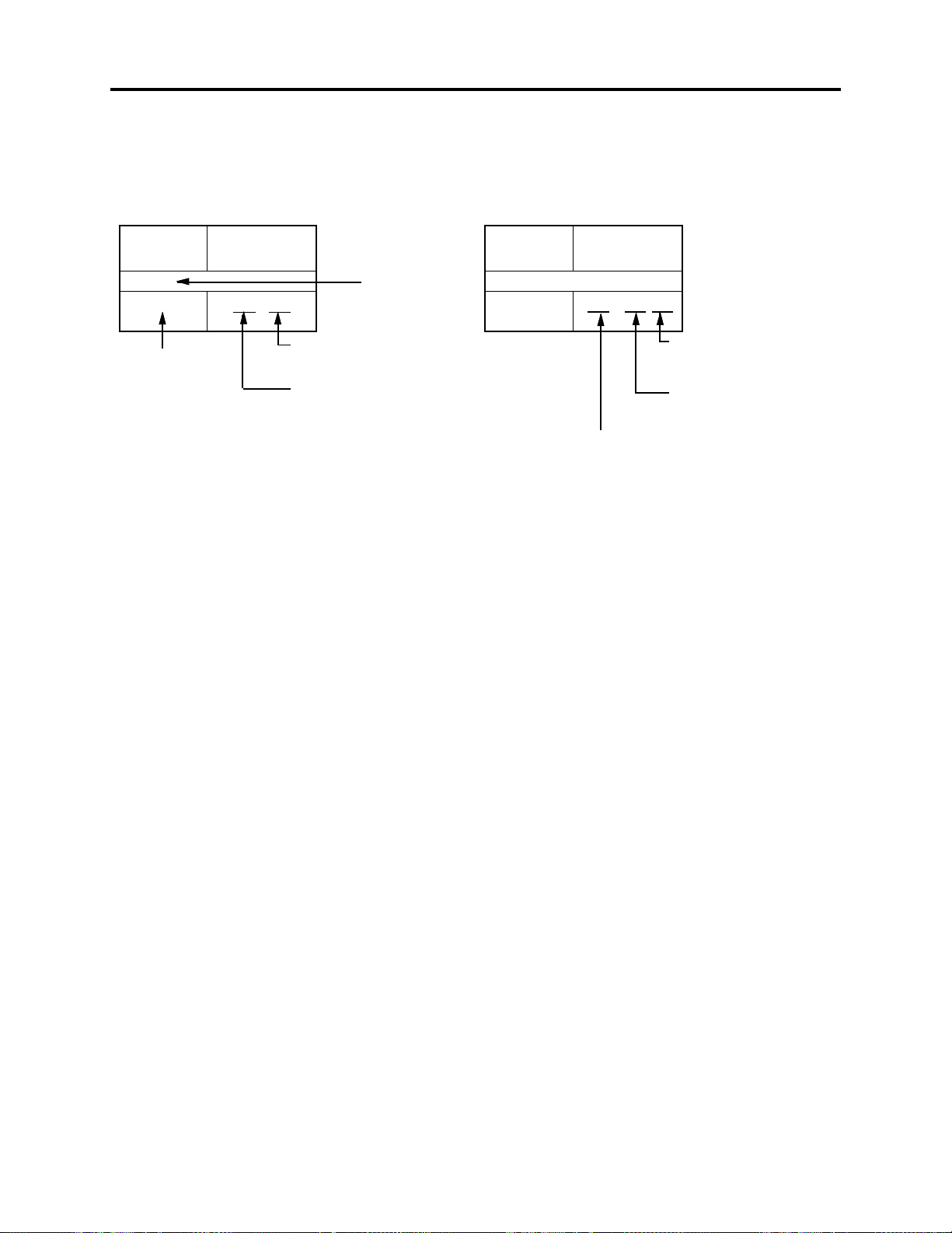
(4) Table for indexing locations of parts
This table shows locations of each part on circuit board diagrams. The locations are indicated using
the guide scales on the external lines of diagrams.
2) Two diagrams indicated for each board1) One diagram indicated for each board
Symbol
No.
IC
IC1201
Symbol no.
Parts
Location
2 A
Type of part
Zone "A" on circuit board
diagram
Zone "2" on circuit board
diagram
Symbol
No.
IC
IC1201
A: Shows side A
B: Shows side B
Parts
Location
A - 2 A
Zone "A" on board
diagram
Zone "2" on board
diagram
1 - 6
2
General Description
2-1 Overview
The DZ-MV580E has been made more compact than the previous DZ-MV380E; the DZ-MV550E has
been made compact than the DZ-MV350E.
The DZ-MV580E has a CCD image sensor with a total of 1,020,000 pixels and a high-performance
optical 10-power zoom.
The DZ-MV550E has a CCD image sensor with a total of 800,000 pixels and an optical 18-power
zoom.
2-1-1 Servicing method
Refer to the following table and perform the designated, appropriate servicing. Any changes that
occur in the service method will be published using service bulletin, etc.
Do not perform any servicing other than that described in this manual.
Parts Name
Disc drive unit
Servicing method
Unit replacement.
Which incorporates the
DRV-R, MOD and HDM
DISC DRIVE
UNIT
FRT-H/FRT
CIRCUIT
BOARD
MR CIRCUIT BOARD
(In the LCD unit)
circuit boards.
Lens unit
AEL-H/AEL circuit
(*1)
board
DRF-H/DRF circuit
(*1)(*2)
board
FRT-H/FRT circuit
(*1)
board
GYR-H/GYR circuit
(*1)
board
LCD circuit board
MAN-H/MAN circuit
board(*1)
MR circuit board
SAF-H/SAF circuit
(*1)(*4)
board
SEN-H circuit board
(*1)(*5)
SHE-H/SHE circuit
(*1)
board
SWL2 circuit board
SWL3 circuit board
USB/USB-H circuit
(*1)
board
Unit replacement.
Component replacement.
Component replacement.
Component replacement.
Component replacement.
Component replacement.
Circuit board assembly
replacement.
(*3)
Component replacement.
Component replacement.
Component replacement.
Component replacement.
Component replacement.
Component replacement.
Component replacement.
LENS
UNIT
LCD
CIRCUIT
BOARD
SEN-H
CIRCUIT
BOARD
AEL-H/AEL
CIRCUIT
BOARD
GYR-H/GYR
CIRCUIT
BOARD
USB-H/USB
CIRCUIT
BOARD
Fig. 2-1-1
SHE-H/SHE
CIRCUIT
BOARD
SWL2
CIRCUIT
BOARD
SWL3-H/SWL3
CIRCUIT
BOARD
SAF-H/SAF
CIRCUIT
BOARD
*1: The board names suffixed with “-H” are for DZ-MV580E only.
*2: Film type board that connects MAN-H/MAN circuit board and disc drive unit.
*3: Film type board in LCD unit
*4: Film type board that connects AEL-H/AEL circuit board and SWL2 circuit board.
*5: Applicable only to DZ-MV580E. Although the SEN-H circuit board and lens unit in DZ-MV580E are
assigned as different boards, the circuit board in DZ-MV550E that corresponds to SEN-H is assembled
in the lens unit.
DRF-H/DRF
CIRCUIT
BOARD
MAN-H/MAN
CIRCUIT
BOARD
2 - 1
General Description > Features / Specifications
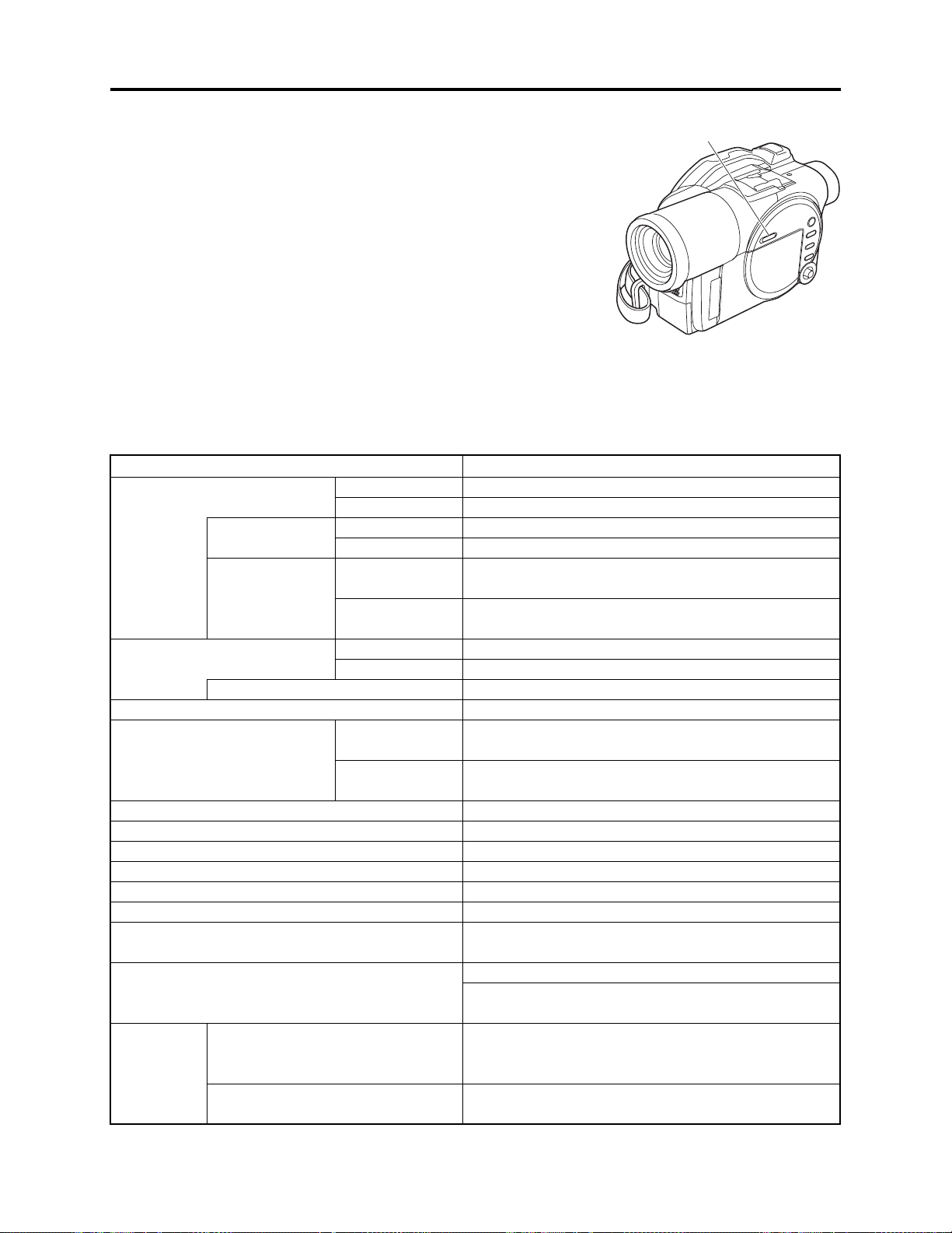
2-2 Features
QUICK MODE switch mounted
The new DVD video camera/recorder has a QUICK MODE switch
that switches the on-screen display between Quick mode and
Normal mode: The new timer of video camera/recorder can easily
operate the screen display in Quick mode.
The Quick mode displays only the fundamental menu items; a
brief explanation of the selected item is displayed across the
bottom of screen.
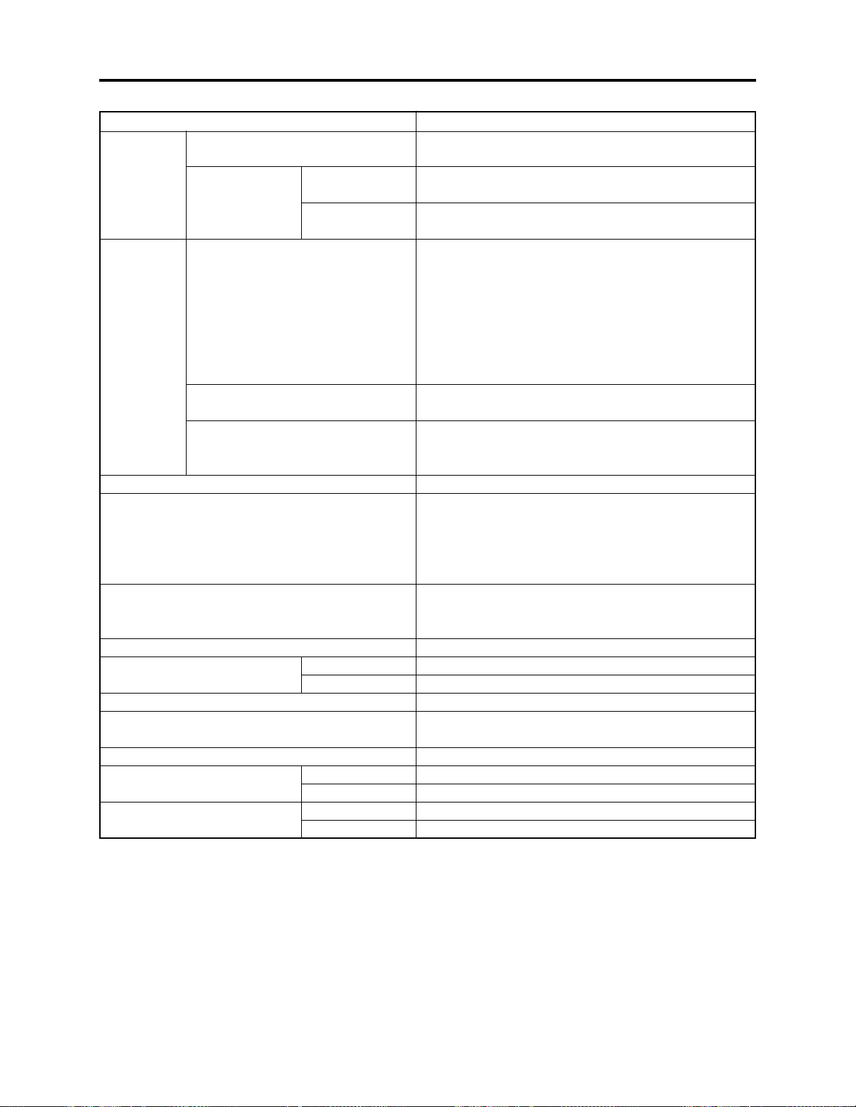
2-3 Specifications
Item
CCD Image Sensor
Total number of
pixels
Number of
effective pixels:
Lens
Filter diameter / Thread pitch:
Focus
Zoom
Required minimum illumination
Viewfinder
LCD monitor
Image Stabilizer
Shutter speed
Self-timer recording
External microphone jack
Recording mode
Maximum
time of
recordable
video
DVD-RAM disc (per side)
DVD-R disc (per side)
DZ-MV580E
DZ-MV550E
DZ-MV580E
DZ-MV550E
DZ-MV580E
DZ-MV550E
DZ-MV580E
DZ-MV550E
DZ-MV580E
DZ-MV550E
1/3.8-inch interlaced
1/6-inch interlaced
Approx. 1,020,000
Approx. 800,000
Video: Approx. 570,000
Photo: Approx. 960,000
Video: Approx. 410,000
Photo: Approx. 410,000
F1.8 - 2.4, f = 3.8 - 38 mm
F1.8 - 2.8, f = 2.1 - 37.8 mm
37 mm / 0.75mm
Auto/Manual
Optical 10×, 240× with digital zoom added (40× for
photo)
Optical 18×, 500× with digital zoom added (40× for
photo)
0.3 lx (When Low Light mode is selected)
0.33-inch color TFT (approx. 110,000 pixels)
2.5-inch color TFT (approx. 120,000 pixels)
Electronic Type
1/50 - 1/4000 second (video)
Photo recording only
Ø 3.5 mm stereo mini-jack
(a plug-in power type microphone cannot be used)
Video with audio (DVD-RAM disc, DVD-R disc)
Photo (DVD-RAM disc, SD memory card,
MultiMediaCard)
XTRA mode: Approx. 18 min.
FINE mode: Approx. 30 min.
STD mode: Approx. 60 min.
FINE mode: Approx. 30 min.
STD mode: Approx. 60 min.
QUICK MODE SWITCH
Fig. 2-2-1
Specifications
2 - 2
General Description > Specifications
Maximum
number of
recordable
photos
Recording
format
Audio playback format
Recording media
Jacks
Battery system
Power consumption (when
recording with LCD monitor off )
Dimensions (W × H × D, excluding projections)
Operating temperature (humidity)
Storage temperature
Weight (without battery and
disc)
Total weight when recording
(when using battery)
DVD-RAM disc (per side)
SD memory
DZ-MV580E
Card
(When using
DZ-MV550E
32MB card)
DVD-RAM disc
DVD-R disc
Card
DZ-MV580E
DZ-MV550E
DZ-MV580E
DZ-MV550E
DZ-MV580E
DZ-MV550E
SpecificationsItem
999 However, if video and photo are mixed on one disc,
the recordable number will decrease
Approx. 50 (in FINE mode) Varies depending on the
recording quality and the type of card
Approx. 220 (in FINE mode) Varies depending on the
recording quality and the type of card
Video: Conforming to DVD video recording
(DVD-VR) format
Audio: MPEG Audio layer 2
Photo: Simultaneous recording, conforming to JPEG
format (DZ-MV580E: 1280 × 960 pixels, DZ-
MV550E: 640 × 480 pixels) and DVD video
recording (DVD-VR) format (704 × 576 pixels).
[JPEG of line input
Video: Conforming to DVD video format
Audio: MPEG Audio layer 2
Photo: Conforming to JPEG (DZ-MV580E: 1280 × 960
pixels, DZ-MV550E: 640 × 480 pixels) format
[Line input
(*1)
: 640 × 480 pixels]
MPEG Audio layer 2, Dolby AC3
8 cm DVD-RAM disc (conforming to DVD-RAM Ver. 2.1)
8 cm DVD-R disc
(conforming to DVD-R for General Ver. 2.0)
SD memory card
MultiMediaCard
Video/audio input
(*1)
External microphone input × 1
PC connection terminal (connected to PC USB port) × 1
Lithium-ion
Approx. 4.4 W (DVD-RAM disc used, FINE mode)
Approx. 4.1 W (DVD-RAM disc used, FINE mode)
Approx. 64 × 89 × 146 mm
0 - 40°C (less than 80%)
0 - 30°C when connected to PC
-20 - 60°C
Approx. 500 g
Approx. 490 g
Approx. 585 g
Approx. 575 g
(*1)
/output × 1
: 640 × 480 pixels]
2 - 3
General Description > Specifications
SpecificationsItem
Provided accessories AC adapter/charger (model DZ-ACS1)
Power cable
DC power cord,
Battery (model DZ-BP14S)
AV/S input
Infrared remote control (model DZ-RM3W)
Lithium battery for remote control (model CR2025)
Lens cap
Lens cap string
Shoulder strap
Software CD-ROM
PC connection cable
Single-sided 8cm DVD-RAM disc (in round DVD holder)
*1: The line input function is provided in the following models:
DZ-MV580E(AU)/MV580E(SW)/MV580E(SWH)
DZ-MV550E(AU)/MV550E(SW)/MV550E(SWH)
The symbols in parentheses ( ) in the above model names show the destinations and are displayed only
on packing box.
Refer to “2-5 Differences in Rating Labels and Difference in Function” when checking the body of DVD
video camera/recorder, to judge whether or not it is equipped with the line input function (destination).
(*1)
/output cable
Specifications of DZ-ACS1 AC Adapter/Charger
Item
Power supply
Input capacity
DC output (max.)
Charge output
Weight
External dimensions (W x H x D)
Ambient temperature for operation
Allowable relative humidity
100 - 240 V AC, 50/60 Hz
26VA (at 100V AC)
7.9 V, 1.4 A
8.4 V, 0.65A
105 g
61 × 32 × 91 mm
5 - 35°C
40 - 80%
Specifications are subject to change without notice for the purpose of improvement.
Specifications
2 - 4
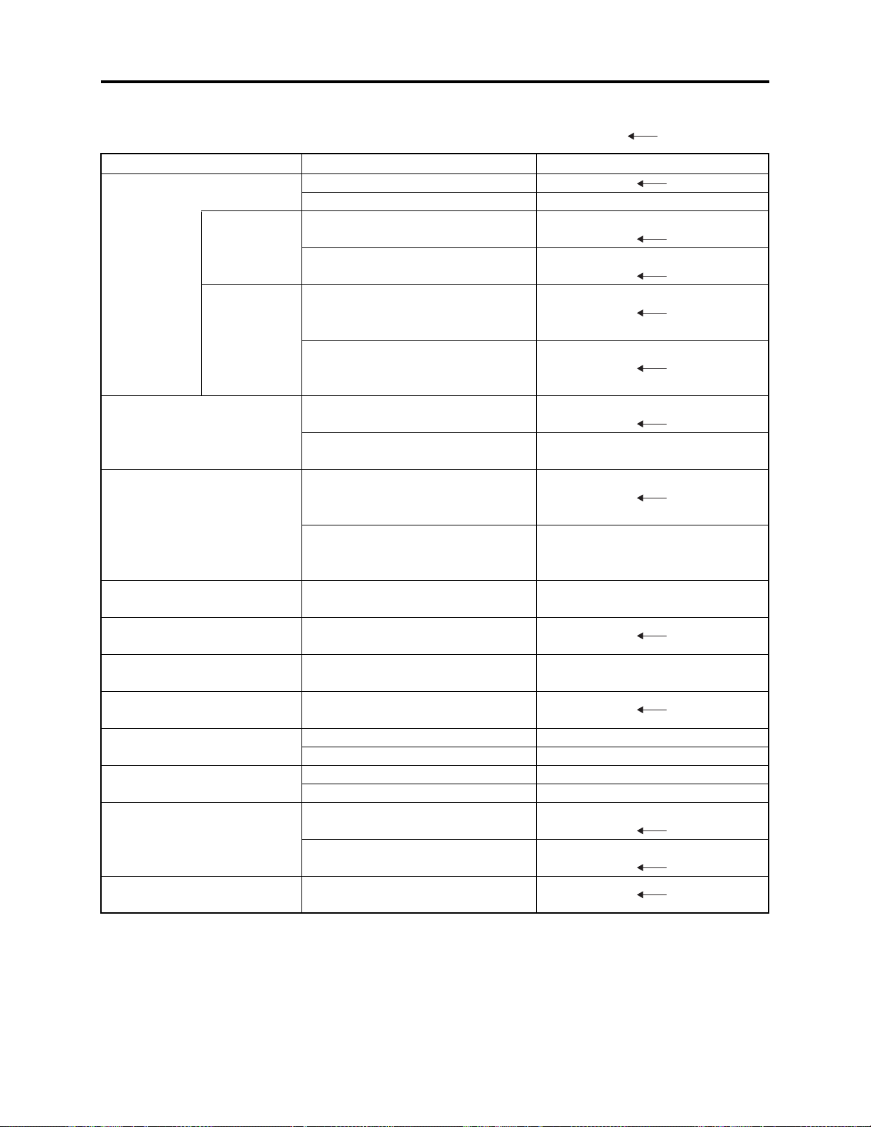
General Description > Major Differences from Previous Models
2-4 Major Differences from Previous Models
: Same as on left
Item
CCD
Total number
of pixels
Number of
effective pixels
Lens
Zoom
Filter diameter
Required minimum
illumination
Viewfinder
LCD monitor
Power consumption
Weight
Accessory Shoe
PC connection terminal
[USB standard]
DZ-MV580E/MV550E
DZ-MV580E: 1/3.8-inch interlaced
DZ-MV550E: 1/6-inch interlaced
DZ-MV580E:
Approx. 1,020,000 pixels
DZ-MV550E:
Approx. 800,000 pixels
DZ-MV580E:
Video: Approx. 570,000 pixels
Photo: Approx. 960,000 pixels
DZ-MV550E:
Video: Approx. 410,000
Photo: Approx. 410,000
DZ-MV580E:
F1.8 - 2.4 / f = 3.8 - 38 mm
DZ-MV550E:
F1.8 - 2.8 / f = 2.1 - 37.8 mm
DZ-MV580E:
Optical 10×, 240× with digital zoom
added (40× for photo)
DZ-MV550E:
Optical 18×, 500× with digital zoom
added (40× for photo)
37 mm
0.3 lx
(When Low Light mode is selected)
0.33-inch color TFT
(approx. 110,000 pixels)
2.5-inch color TFT
(approx. 120,000 pixels)
DZ-MV580E: Approx. 4.4 W
DZ-MV550E: Approx. 4.1 W
DZ-MV580E: Approx. 500 g
DZ-MV550E: Approx. 490 g
DZ-MV580E: Power/Control terminal
provided
DZ-MV550E: Power/Control terminal
not provided
Type mini-B
[USB 2.0]
DZ-MV380E/MV350E
DZ-MV380E:
DZ-MV350E: 1/4-inch interlaced
DZ-MV380E:
DZ-MV350E:
DZ-MV380E:
DZ-MV350E:
DZ-MV380E:
DZ-MV350E:
F1.8 - 2.5 / f = 3.15 - 31.5 mm
DZ-MV380E:
DZ-MV350E:
Optical 10×, 240× with digital zoom
added (40× for photo)
DZ-MV380E: 37 mm
DZ-MV350E: 30.5 mm
0.44-inch color TFT
(approx. 110,000 pixels)
DZ-MV380E: Approx. 5.0 W
DZ-MV350E: Approx. 4.7 W
DZ-MV380E: Approx. 505 g
DZ-MV350E: Approx. 480 g
DZ-MV380E:
DZ-MV350E:
2 - 5

General Description > Major Differences from Previous Models
Item DZ-MV580E/MV550E DZ-MV380E/MV350E
Dimensions (W × H × D) and
shape
DZ-MV580E:
Approx. 64 × 89 × 146 mm
DZ-MV380E:
Approx. 60 × 93 × 148 mm
AC adapter/charger
Battery pack
Infrared remote control
AV input
(*1)
/output jack
Shape of DVD holder
PC editing kit
Disc protect
EIS function
QUICK MODE switch
Line input function
Number of pixels for video
(MPEG2)
Number of pixels for JPEG
photo during camera recording
Number of pixels for MPEG
photo during camera recording
(When using disc)
DZ-MV550E:
Approx. 64 × 89 × 146 mm
DZ-ACS1
Provided: DZ-BP14S
(7.2V/1360mA)
Optional: DZ-BP14SW
(7.2V/1360mA)
DZ-RM3W
Pin 8 type
Round DVD holder
Provided
Software disc-protect
DZ-MV580E: Video mode only
DZ-MV550E: Video and photo
mode
Provided
Varies depending on the model
(destination)
(*1)
XTRA/FINE: 704 × 576 pixels
STD/LPCM: 352 × 576 pixels
DZ-MV580E: 1280 × 960 pixels
DZ-MV550E: 680 × 480 pixels
704 × 576 pixels
DZ-MV350E:
Approx. 57 × 89 × 134 mm
Pin 10 type
DZ-MV380E:
DZ-MV350E: Video mode only
Not provided
Not provided
DZ-MV380E:
DZ-MV350E:
2 - 6

General Description > Major Differences from Previous Models
Item DZ-MV580E/MV550E DZ-MV380E/MV350E
Number of pixels for photo
during line input recording
File size of photo
*1: The line input function is provided in the following models:
DZ-MV580E(AU)/MV580E(SW)/MV580E(SWH)
DZ-MV550E(AU)/MV550E(SW)/MV550E(SWH)
The symbols in parentheses ( ) in the above model names show the destinations and are displayed only
on packing box.
Refer to “2-5 Differences in Rating Labels and Difference in Function” when checking the body of DVD
video camera/recorder, to judge whether or not it is equipped with the line input function (destination).
JPEG: 640 × 480 pixels
(*1)
MPEG: 704 × 576 pixels
DZ-MV580E:
FINE: Approx. 512KB
NORM: Approx. 384KB
ECO: Approx. 256KB
DZ-MV550E:
FINE: Approx. 128KB
NORM: Approx. 64KB
ECO: Approx. 32KB
Line input function is not provided.
DZ-MV380E:
DZ-MV350E:
2-5 Differences in Rating Labels and Difference in Function
Check the mark in rating label to identify the destination, and determine any difference in function
by checking the body of DVD video camera/recorder.
There are five models each of DZ-MV580E and DZ-MV550E, headed for different destinations noted
in parentheses ( ) as shown in the table below: The key difference is whether the line input
function is provided or not.
The destinations in parentheses ( ) are shown only on packing boxes: They are shown in rating
labels on the DVD video camera/recorder bodies.
Model
Label
DZ-MV580E
DZ-MV550E
HITACHI
DVD VIDEO CAMERA/RECORDER
MODEL NO.
MODELO
Hitachi, Ltd
MADE IN JAPAN/FABRICADO EN JAPON
SERIAL NO.
N' de serie
7.9V/7.2V
DZ-MV580E(UK)
DZ-MV550E(UK)
HITACHI
DVD VIDEO CAMERA/RECORDER
MODEL NO.
MODELO
Hitachi, Ltd
MADE IN JAPAN/FABRICADO EN JAPON
SERIAL NO.
N' de serie
Approved
7.9V/7.2V
BEAB
DZ-MV580E(AU)
DZ-MV580E(SW)
DZ-MV580E(SWH)
DZ-MV550E(AU)
DZ-MV550E(SW)
DZ-MV550E(SWH)
HITACHI
DVD VIDEO CAMERA/RECORDER
MODEL NO.
MODELO
Hitachi, Ltd
MADE IN JAPAN/FABRICADO EN JAPON
SERIAL NO.
N' de serie
7.9V/7.2V
N155
Line input function
Not provided
2 - 7
Not provided
Provided

General Description > Compatibility of Recorded Discs
2-6 Compatibility of Recorded Discs
Discs recorded or edited on DZ-MV580E/MV550E can also be recorded, edited and played back on
other DVD video camera/recorders, except for those for which disc-protect
Discs recorded or edited on other DVD video camera/recorders can also be recorded, edited and
played back on DZ-MV580E/MV550E: However, the DZ-MV100E cannot handle DVD-R disc, and a
scene memo recorded on the DZ-MV100E Disc Navigation function cannot be played back or edited
on another DVD video camera/recorder.
*1: The DZ-MV380E/MV350E can release the disc-protect that has been set on DZ-MV580E/MV550E.
Therefore, if the disc-protect set on DZ-MV580/MV550 is released, the discs can be recorded, edited
and played back on DZ-MV380E/MV350E.
(*1)
has been set.
2 - 8

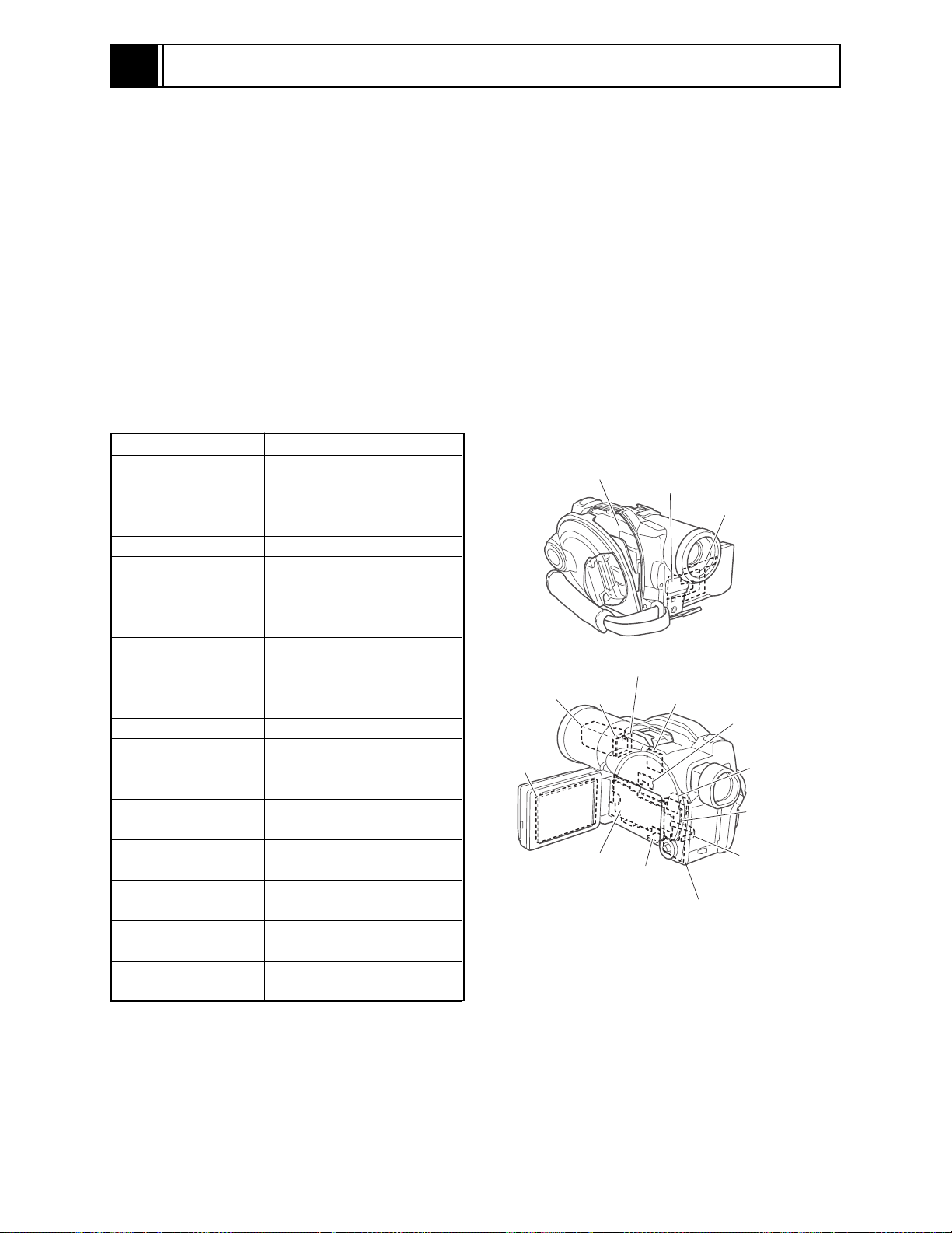
General Description > Names of Parts
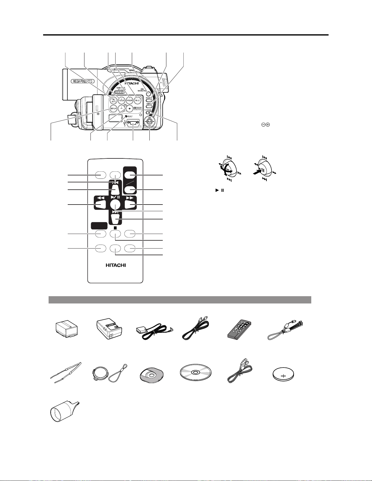
2-7 Names of Parts
10 11
2
13 4
(Inside the cover)
Although the external appearances of DZMV550E and DZ-MV580E are different, the
method of operating both models is identical.
DZ-MV580E illustrations are used in this
manual.
15 16 17 2118
22 23 25 2726
24
56 89
A/V
MIC
19
7
12 13
20
BATTERY EJECT
(Bottom)
1 Infrared receiver
When the remote control is used to operate the
DVD video camera/recorder, this receiver will
receive the infrared signal.
2 Lens cap string attachment hole
3 Recording indicator
The red indicator will light during recording.
4 Stereo microphone
5 Optical 18 x zoom lens (DZ-MV550E)
Optical 10x zoom lens (DZ-MV580E)
6 Lens hood
Always remove this lens hood when using
generally available tele-conversion or wideconversion lens.
7 Lens cover
You can replace the lens cover with either of the
two covers provided.
8 Zoom lever
Push the lever to the T side for telephoto, or to
the W side for wide-angle.
9 Accessory shoe
14
Only for DZ-MV580E:
The optional video flash, etc. can be attached
here. (See the instruction manual of device to be
attached for details.)
10 External microphone jack
11 AV output jack (P. 80)
12 2.5" type liquid crystal display (inside)
13 QUICK MODE switch
To switch the menu display on screen between
Normal mode and Quick mode.
14 BATTERY EJECT switch
The BATTERY EJECT switch is located on the
bottom of this DVD video camera/recorder:
Slide it when removing the battery.
15 Viewfinder
16 Diopter control
To adjust the focus of image appearing in the
viewfinder. (Pull out the viewfinder.)
17 ACCESS/PC indicator
Will blink or light when the disc in DVD video
camera/recorder is accessed (write or read is
executed) or the DVD video camera/recorder
is connected to PC.
18 DISC EJECT button
Press down and release this button to open the
disc guide.
19 Disc insertion block
20 CARD ACCESS indicator
21 Card insertion block
22 Battery attachment platform
23 Record button (REC)
24 Power switch
25 LOCK switch
It is recommended that you set the LOCK
switch to (to the left) to prevent the power
switch in the " VIDEO" position from
accidentally moving to" PHOTO".
26 Speaker
27 Hand strap
2 - 9
General Description > Names of Parts
28 29 30 31 32 33 34
4036 37 38 3935
DIGITAL
ZOOM
DZ-RM3W
ZOOM
T
DISPLAY
DELETESELECT
47
W
48
49
50
51
52
53
54
55
41
42
43
44
45
46
REC
DISC
NAVIGATION
MENU
28 FULL AUTO button
To switch the DVD video camera/recorder to full automatic.
29 FOCUS button
To switch between manual focus and autofocus.
30 EXPOSURE button
Press this button to adjust the exposure.
31 BLC (backlight compensation) button
Press this button when subject is being lighted from rear.
32 DISC NAVIGATION button
33 SELECT button
34 MENU button
Press this button to display the menu for setting camera functions
and Disc Navigation.
35 DISPLAY (Screen display) button
Press this button to display the details of image being played back or
camera setting status, or switch the display off.
36 Volume control buttons (VOL)/ buttons
To adjust the volume of sound from speaker,etc.
37 RESET button
To reset all settings to defaults (status when the DVD video camera/
recorder was shipped from the factory)
38 PC connection terminal (TO PC)
39 Joystick
Move the joystick to select a scene or menu item, and then press the
center ( ) to play back the scene, pause it, or designate an option
/
of the menu.
40 Stop/cancel button
To end playback or cancel setting of menu.
41 REC button
42 DIGITAL ZOOM button
43 Reverse skip button
44 Reverse search button
45 DISC NAVIGATION button
46 MENU button
47 ZOOM T button
48 ZOOM W button
49 Forward search button
50 Play/pause button
51 Forward skip button
52 DISPLAY button
53 Stop button
54 DELETE button
55 SELECT button
* The buttons on remote control will function the same as those on
DVD video camera/recorder.
Accessories
Battery
(model: DZ-BP14S)
Shoulder strap Lens cap and lens
2 lens covers for
replacement
AC adapter/
chargre
(model: DZ-ACS1)
cap string
DC power cord AC power cable Infrared remote
Single-side 8 cm
DVD-RAM disc
(in Round DVD
Holder)
Software CD-ROM PC connection
control
(model: DZ-RM3W)
cable
2 - 10
AV/S output cable
Lithium battery
(model: CR2025)
General Description > List of Abbreviations and Terms for DVD Video Camera/Recorders
2-8 List of Abbreviations and Terms for DVD Video
Camera/Recorders
Index
Abbreviation/Term
A
AC3
C
CPRM
D
DCF
Dolby AC3
DPOF
DVD
DVD Forum
DVD-Audio
DVD-R
DVD-RAM
DVD-ROM
DVD-RW
DVD-Video
DVD Video
Format
DVD Video
Recording Format
E
Exif
F
FireWire
I
IEEE1394
Interlaced CCD
i-LINK
J
JEIDA
JEITA
JPEG
L
LCD
LPCM
M
MMC
MMCA
Explanation
See Dolby AC3.
Content Protection for Recordable Media: Copyright protection function that is
suitable for online distribution of music.
Design rule for Camera File system standard: This camera file system standard,
established by JEIDA (now merged to JEITA).
Audio coding format developed by Dolby Laboratories in U.S, also simply referred
as AC3 format: Supports 5-channel full-range sound and one channel for sub-woofer
sound playback.
Digital Print Order Format: DPOF allows user to record print information along
with photos on storage media to facilitate printing of photos.
Digital Versatile Disc. A huge amount of digital data for video (movie) and audio
can be recorded on this disc, whose size is the same as CD.
International organization that formulates the technical standards of DVD
One type of DVD standard disc, on which high-quality audio can be recorded
One type of DVD standard disc, to which writing once is possible (recordable type)
One type of DVD standard disc, to which writing up to 100,000 times is possible
One type of DVD standard disc, to which data for computer can be recorded
One type of DVD standard disc, to which writing up to 1000 times is possible
One type of DVD standard disc, on which high-quality video and audio can be
recorded
Video recording/playback standard that applies to DVD-Video, DVD-R and DVDRW
Video recording/playback standard that applies to DVD-RAM and DVD-RW: This
allows versatile editing functions, differing from the DVD Video Format.
Exchangeable image file format. File format used for recording photos on digital
cameras, established by JEIDA (now merged to JEITA).
See IEEE1394.
Also referred to as FireWire or i-LINK: Standard for serial interface that connects
PC and peripheral devices
This CCD scans one image twice (scans roughly once and interpolates between first
scanning lines the second time) and interlaces the images obtained by scanning
twice to create a one-image signal.
See IEEE1394.
JEIDA stands for Japan Electronic Industry Development Association.
JEITA stands for Japan Electronics and Information Technology Industries
Association, which came into existence when JEIDA merged with EIAJ (Electronic
Industries Association of Japan).
JEITA has established Exif and DCF standard.
Joint Photographic Expert Group: International standard format for compressing
still images
Liquid Crystal Display. LCD formats include STN and TFT.
Linear Pulse Code Modulation. Also referred to as linear PCM. LPCM is a format
that digitizes analog audio data during recording and converts it to analog data
during playback.
See MultiMediaCard.
See MultiMediaCard Association.
2 - 11
General Description > List of Abbreviations and Terms for DVD Video Camera/Recorders
Index Abbreviation/Term Explanation
M
MPEG
MPEG Audio
Layer 2
MultiMediaCard
MultiMediaCard
Association
OSTA
O
S
SCSI
SDA
SD Card
Association
SDMI
SD Memory Card
SecureMMC
Secure
MultiMediaCard
Software discProtect
STN LCD
T
TFT LCD
U
UDF
USB
V
VBR
Motion Picture Experts Group: Standard related to compression of digital video and
audio. MPEG2 is a higher standard of MPEG and is applied to video (movie)
requiring higher quality.
One of three audio compression standards (layers 1-3) defined by MPEG
Also referred to as MMC. Compact memory card, 32 mm long × 24 mm wide × 1.4
mm thick
Also referred to as MMCA. This association promotes the widespread use of
multimedia cards.
Optical Storage Technology Association, which is an international industry
organization that promotes recordable optical storage used to store computer data
and images.
Small Computer System Interface: A standard for connecting computer and
peripheral devices. Frequently notated by prefixing or suffixing the number that
indicates the data transfer rate, and First, Ultra, Wide, etc., to SCSI.
See SD Card Association.
Also referred to as SDA. This organization promotes the popularization of SD
memory card.
Secure Digital Music Initiative: This conference was established by hardware
makers, the Recording Industry Association of America (RIAA) and music industry
companies, to protect copyrights of musical compositions.
Formally named Secure Digital Memory Card. This compact memory card, 32 mm
long × 24 mm wide × 2.1 mm thick, is equipped with an advanced copyright
protection function.
See Secure MultiMediaCard.
Also referred to as SecureMMC. This compact memory card has multimedia card
specifications, to which an advanced copyright protection function is added.
Unusable on the DVD video camera/recorder.
This function writes the protect information to DVD-RAM disc to prevent accidental
erasure. Software Disc-Protect is included in DVD-RAM disc specifications defined
by DVD Forum.
Super-Twisted Nematic Liquid Crystal Display: This type of color LCD is inferior to
TFT LCD in coloring, view angle, etc.
Thin Film Transistor Liquid Crystal Display: This type of color LCD features clear
display, high contrast, wide view angle, etc.
Universal Disc Format, which is a file format of recordable disc defined by OSTA.
The version 2.01 UDF is used on DVD video camera/recorder.
Universal Serial Bus: Standard of serial interface that connects PC and peripheral
devices. Two versions - USB1.1 and USB2.0, with different data transfer rates exist at present.
Stands for Variable Bit Rate: This format of coding audio and video varies the
amount of data depending on the subject image.
2 - 12
2a
General Description
2-1a Overview
The DZ-MV1000E(UK) is a DVD video camera/recorder that is the result of changes in some
structural components of DZ-MV550E(UK) and accessories: Specifications and functions are
identical to those of DZ-MV550E(UK).
2-1-1a Servicing method
The service method for the DZ-MV1000E(UK) is the same as that for DZ-MV550E(UK).
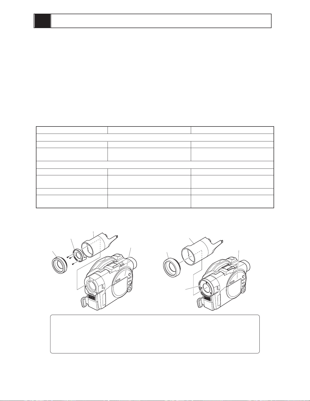
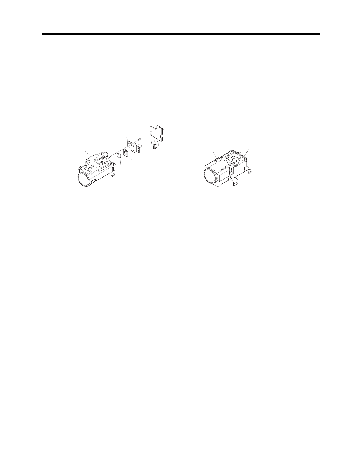
2-2a Differences from DZ-MV550E(UK)
Table 2-2-1 Differences from DZ-MV550E(UK)
Item
L Cover
Filter Piece
Replaccement lens cover
Single sided 8cm DVD-RAM
(in round DVD holder)
Infrared remote control
Lithum battery for infrared
remote control
DZ-MV1000E(UK) DZ-MV550E(UK)
Lens cover
Filter piece
Hood
DZ-MV1000E(UK)
Structural components
Printed moodel name: DZ-MV1000E
User replaceable lens cover is not
available
Accessories
Not provided
Not provided
Not provided
Not provided
L cover
(Printed model
name )
Lens cover
Hood
DZ-MV550E(UK)
Printed moodel name: DZ-MV550E
User replaceable lens cover is
available
Provided (two colors)
Provided
Provided (DZ-RM3W)
Provided (CR2025)
L cover
(Printed model
name )
Filter piece
(in front case)
Information:
Since user cannot replace the DZ-MV1000E(UK) lens cover, the lens cover cannot be
removed unless the filter piece
*1: On DZ-MV550E it is not necessary to remove the filter piece when removing the lens
cover.
(*1)
is also removed.
Fig. 2-2-1 Differences in Structural Components
2 - 13

3
Description of Operation
3-1 Description of Structure
(1) Configuration and locations of circuit boards
The configuration of circuit boards in DZ-MV580E/MV550E and their locations are very similar to
those in the base models DZ-MV380E/MV350E, except for whether the FAF circuit board is
provided or not.
The DZ-MV380E/MV350E had the FAF circuit board between the FRT and AEL circuit boards:
The DZ-MV580E/MV550E does not have this, since the FRT-H/FRT circuit board is directly
connected to AEL-H/AEL circuit board.
LENS
UNIT
LCD
CIRCUIT
BOARD
DISC DRIVE
UNIT
SEN-H
CIRCUIT
BOARD
AEL-H/AEL
CIRCUIT
BOARD
DZ-MV580E
GYR-H/GYR
CIRCUIT
BOARD
USB-H/USB
CIRCUIT
BOARD
MR CIRCUIT
BOARD
(In the LCD unit)
FRT-H/FRT
CIRCUIT
BOARD
SHE-H/SHE
CIRCUIT
BOARD
SWL2
CIRCUIT
BOARD
SWL3-H/SWL3
CIRCUIT
BOARD
DRF-H/DRF
CIRCUIT
BOARD
MAN-H/MAN
CIRCUIT
BOARD
SAF-H/SAF
CIRCUIT
BOARD
Fig. 3-1-1
LENS
UNIT
LCD
CIRCUIT
BOARD
DISC
DRIVE
UNIT
SEN
CIRCUIT
BOARD
AEL
CIRCUIT
BOARD
DZ-MV380E
FAF
CIRCUIT
BOARD
GYR
CIRCUIT
BOARD
USB
CIRCUIT
BOARD
SHE
CIRCUIT
BOARD
Circuit board
equivalent to
SWL2
MR CIRCUIT
BOARD
(In the LCD unit)
FRT
CIRCUIT
BOARD
DRF
CIRCUIT
BOARD
MAN
CIRCUIT
BOARD
SAF
CIRCUIT
BOARD
3 - 1
Description of Operation > Description of Structure
(2) Differences in structure between DZ-MV580E and DZ-MV550E
There are two major differences in structure between DZ-MV580E and DZ-MV550E:
1) Accessory shoe
The accessory shoe on DZ-MV580E has a power/control terminal, but the accessory shoe on DZMV550E doesn’t.
2) Lens unit
The lens unit in DZ-MV550E includes the cushion, crystal filter, CCD image sensor and SEN-H
circuit board, which are discrete from the lens unit in DZ-MV580E.
CCD
LENS
UNIT
IMAGE
SENSOR
CRYSTAL
FILTER
CUSHION
SEN-H
CIRCUIT
BOARD
LENS
UNIT
Circuit board equivalent
to SEN-H
DZ-MV580A LENS UNIT
DZ-MV550A LENS UNIT
Fig. 3-1-2
3 - 2
Description of Operation > Description of Newly Adapted Technology
3-2 Description of Newly Adapted Technology
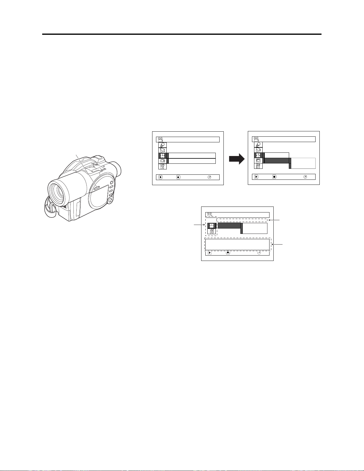
(1) QUICK MODE switch
The QUICK MODE switch changes over the screen for various settings and for Disc Navigation
between Quick mode and Normal mode.
The Quick mode displays only the fundamental menu items and the brief explanation on the
selected item/function is displayed across the bottom of screen.
Fig. 3-2-1 shows the position of QUICK MODE switch and an example of display screens.
Date/time setting screen in Normal mode:
2-step operation until setting screen appears
Date Setup
Date Mode
Date Set
ENTER RETURN
1 / 1 / 2004
0:00
RAM
QUICK MODE switch
Date Setup
Date Mode
Date Set
ENTER RETURN
:
D/M/Y
RAM
Date/time setting screen in Quick mode:
1-step operation until setting screen appears
Date Setup
Camera function setup,
Record function setup
and LCD monitor setup
are omitted.
(*1)
Date Set
Set the current date and
time.
ENTER RETURN
1 / 1 / 2004
0:00
RAM
*1: The Record Functions Setup icon will appear on the following models, showing that they have the line
input function:
DZ-MV580E(AU)/MV580E(SW)/MV580E(SWH)
DZ-MV550E(AU)/MV550E(SW)/MV550E(SWH)
Display mode
setting is omitted.
Item/function
explanatory
display
Fig. 3-2-1
3 - 3

4
Troubleshooting
4-1 Procedure for Troubleshooting
Perform troubleshooting in the order shown in Fig. 4-1-1.
Updating
unneeded
Trouble
Diagnosis
(section 4-7)
Updating
needed
No improvement
after updating
No improvement
Check
phenomenon
No message or
error code
*1
appears
Message
*1
appears
Error code
*1
appears
Error codes not included in
service manual appear
Problem guide
(section 4-2)
Messages and
Troubleshooting
(section 4-3)
Major Error
Codes and
Troubleshooting
(section 4-4-3)
Check
troubleshooting
with the factory
No improvement
System reset
(section 4-5)
No improvement
Check firmware
version
(section 4-6-1)
Update firmware
(section 4-6-2)
: Phenomenon
: Troubleshooting
: Check
*1: Messages and error codes will appear on LCD monitor or in viewfinder.
Fig. 4-1-1
Note:
1) Before troubleshooting or servicing, be sure to obtain customer approval for the following:
4-5-1 List of items to be reset
Check
troubleshooting
with the factory
a) The image data stored on disc may be lost depending on the details and situation of fault
(defect).
b) The date/time and various settings, including video recording mode, designated by customer
after purchase may in some cases be reset to the defaults before purchase (factory settings).
2) Take note of settings on received product, referring to “4-5 System Resetting/Resetting Camera
Functions”: The notes will be necessary not only for resetting, but for checking defects that occur
under the particular setting conditions.
4 - 1

Troubleshooting > Problem Guide
4-2 Problem Guide
Check the following before judging that this DVD video camera/recorder is faulty.
Symptom
Battery cannot be charged.
Battery weakens fast.
The CHARGE indicator on
AC adapter/charger is
blinking.
Power turns off immediately
after being turned on.
Power goes off unexpectedly.
Power cannot be turned off.
Cause and Correction
Power supplies
Is the DC power cord connected to AC adapter/charger?
Unplug it. If the DC power cord is connected, the AC adapter/charger will not
enter the charge status.
Is the battery abnormally hot?
Remove the battery from AC adapter/charger, leave it as is until it cools down,
and then charge it again.
Has the battery been unused for a long time?
Remove the battery from AC adapter/charger, and then reattach it. If the
battery is still not charged, it may be dead: Purchase a new one.
**
* If the battery does not charge after you try the above four procedures, it may
**
be dead: Purchase a new battery.
Is the ambient temperature is too low or high?
Always charge the battery at 10 - 30°C.
Are you using the DVD video camera/recorder where the temperature is low?
A fully charged battery may be discharged sooner than usual at low
temperatures. Keep extra batteries on hand.
Battery may be dead: Replace with a new one.
The performance of battery will deteriorate if it is used for an extended period of
time or frequently.
Is the ambient temperature is too low or high?
Always charge the battery at 10 - 30°C.
The battery may be over-discharged.
Continue charging: The CHARGE indicator will change to a steady light, and
the battery will be charged normally.
Is battery charged?
Charge it.
Is Power Save specified "On"?
The specifications state that the powered DVD video camera/recorder
automatically turns off if it is left for as long as 5 minutes without performing
recording or playback, with "Power Save: On" specified. Set the power switch to
"POWER OFF", and then turn this DVD video camera/recorder on again. To stop
automatic power off, specify "Power Save: Off".
Execute system reset (disconnect the battery or AC adapter/charger, and then
use a fine tipped pen, etc. to hold down the RESET button for several seconds).
Then connect a battery or AC adapter/charger and make sure the DVD video
camera/recorder accepts operation.
System reset will return the date/time and all items set using menu (except for
LCD settings) to the defaults at the factory. After recovery, reset the date/time
and each setting item as required.
4 - 2

Troubleshooting > Problem Guide
Symptom Cause and Correction
During recording
Pressing the REC button
will not start recording.
Recording starts but stops
immediately.
Power switch does not
change to PHOTO (disc).
LCD screen is hard to see.
Black dots or red, blue or
green dots always lit appear
on LCD screen or in
Viewfinder.
Focus is not correct.
*1: The line input function is provided in the following models:
DZ-MV580E(AU)/MV580E(SW)/MV580E(SWH)
DZ-MV550E(AU)/MV550E(SW)/MV550E(SWH)
The symbols in parentheses ( ) in the above model names show the destinations and are displayed only
on packing box.
Refer to “2-5 Differences in Rating Labels and Difference in Function” when checking the body of DVD
video camera/recorder, to judge whether or not it is equipped with the line input function (destination).
Is input image copy-guarded?
The specifications state that the DVD video camera/recorder cannot record a
copy-guarded image. [Applies only to models that have the line input function
Does dirt or fingerprint adhere to
disc, or is disc scratched?
Clean the disc. If there is still no
improvement, replace the disc.
Is some other AV device directly connected to the AV input/output jack of the
DVD video camera/recorder?
If the AV device is connected via several other devices, such as AV selector, the
video signal may not be transmitted correctly. In such a case, reduce the number
of devices through which the video signal is transmitted, or connect AV device
directly. [Applies only to models that have the line input function
Are you attempting to record image from video game or PC?
Depending on video game or PC, image cannot be recorded on the DVD video
camera/recorder. [Applies only to models that have the line input function
Is the LOCK switch beside the power switch set to the left? Switch it to the right
to release the lock.
Has brightness of LCD screen been adjusted?
Stop recording and adjust the brightness.
Is the DVD video camera/recorder being used outdoors?
Use the viewfinder. When using LCD monitor, adjust angle so that LCD screen
is not exposed to direct sunlight.
The panels used for LCD monitor and viewfinder of the DVD video camera/
recorder are produced using highly precise technology. However, 0.01% or less of
total pixels may not light (black dots) or may remain lit (red, blue, green dots).
(The effective amount of pixels on LCD panel is 99.99% or more.) This shows the
limitations of the current technology, and does not indicate a fault that will
interfere with the operation of LCD panel or operation of the DVD video camera/
recorder.
Is it difficult to use auto-focus with the subject?
Focus manually.
Does "MF" appear?
The DVD video camera/recorder is set to manual focus. Focus the subject
manually, or release manual focus.
Is the diopter control of viewfinder correctly adjusted?
Adjust the diopter control.
In cases other than the above, set the power switch to "POWER OFF", and then
reset it to a position other then “POWER OFF”.
Disc cleaning method:
Use soft cloth to clean
from inner to outer
circumference in
axial direction.
[Never use solvent.]
(*1)
(*1)
]
]
(*1)
]
4 - 3

Troubleshooting > Problem Guide
Symptom Cause and Correction
Recognition of disc is not
complete.
Pressing the playback
button will not start
playback.
No playback image appears
on TV screen.
Playback picture is
momentarily interrupted.
Poor playback picture.
Playback picture is greatly
distorted.
No sound.
Disc Navigation thumbnails
do not appear.
Photos on card cannot be
played back.
It will take some time to
play back photos on card.
Does dirt or fingerprint adhere to disc, or is disc scratched?
Clean the disc.
Was the image recorded on a device other than this DVD video camera/recorder?
Playback of image recorded on devices other than this DVD video camera/
recorder may be impossible.
Has scene been edited on a device other than this DVD video camera/recorder?
If a scene that was recorded on this DVD video camera/recorder is edited on a
device other than this DVD video camera/recorder, playback may not be possible
on this DVD video camera/recorder.
Is TV input selector set correctly?
If the TV has multiple video input jacks, check to see whether the correct input
jack was selected.
If the DVD video camera/recorder is connected to VCR, set the input selector of
VCR to "external input (LINE)".
Is the DVD video camera/recorder connected to TV correctly?
Check the connections.
Does dirt or fingerprint adhere to disc, or is disc scratched?
Clean the disc.
Was the image input from analog VCR (VHS, 8 mm) and recorded?
The problem may be improved if a VCR equipped with TBC (time base corrector)
circuit is used for playback.
Was recording of external input made with "Frame" specified?
Specify "Field" for "PHOTO Input" in record mode settings. [Applies only to
models that have the line input function (refer to *1 on page 4-3)]
Is the TV volume control set correctly?
Adjust volume control on TV.
Did the image recorded from AV input/output jack have noise or disturbance?
Re-record image with no noise or disturbance. [Applies only to models that have
the line input function (refer to *1 on page 4-3)]
Is a photo recorded on devices other than this DVD video camera/recorder being
played back?
The specifications of this DVD video camera/recorder allow it to play back
photos that are recorded conforming to DCF standard and have 80-4000
horizontal pixels x 60-3000 vertical pixels.
Make sure that the photo to be played back satisfies these specifications. Note
that even photos that satisfy the specifications may not be playable, depending
on the recording status.
The thumbnail of any photo that cannot be played back will appear in single
blue.
Is a photo with a large number of pixels being played back?
It will take some time to play back a photo with a large number of pixels.
During playback
4 - 4

Troubleshooting > Problem Guide
Symptom Cause and Correction
When connected to PC (when using provided software)
No drive icon appears on PC.
A fatal exception 0A error
occurs while installing USB
driver in Windows 2000
Professional
Application is not normally
run on PC.
DISC EJECT button does
not work when the DVD
video camera/recorder is
connected to PC.
Disc cannot be ejected even
by operating Windows
Explorer or applications.
When the time stamp of file
on DVD-RAM disc is viewed
on PC, it is different from
the actual recording date/
time.
Error occurs in playback of
the DVD video camera/
recorder on PC
Error occurs during writing
to DVD-R disc.
Transfer of images stops.
Is the DVD video camera/recorder turned on?
Connect the AC adapter/charger and set the power switch to a position other
than "POWER OFF".
Is PC connection cable properly plugged in?
Plug the PC connection cable connector completely into the DVD video camera/
recorder.
Turn PC off and unplug the PC connection cable: Then restart PC and use the
PC connection cable to connect the DVD video camera/recorder and PC.
The USB device driver installed in PC is not properly recognized.
Restart PC. If the drive icon still does not appear, use "Refresh driver" in Device
Manager to reinstall the USB device driver.
If a yellow "!" mark is attached to some device in Windows Device Manager,
uninstall the USB device driver, and then reinstall it.
It is recommended that you install Windows 2000 Service Pack 3 or later.
Turn the PC and the DVD video camera/recorder off, and try again.
The DISC EJECT button is invalid while the DVD video camera/recorder is
connected to PC.
Start Windows Explorer, right-click the drive icon corresponding to the DVD
video camera/recorder, and then click "Eject".
Was DVD-MovieAlbbumSE (software provided with DVD video camera/recorder)
started?
Terminate DVD-MovieAlbbumSE.
Since the file system of this DVD video camera/recorder is operated on
Greenwich Mean Time (GMT), the time stamp will be GMT.
However, since the time lag information is recorded on disc, the date/time
display on playback screen of this DVD video camera/recorder will be the actual
recording date/time.
If error occurs with USB connection, the transfer rate is not sufficient.
It is recommended that you use a USB terminal conforming to USB2.0 when
connecting the DVD video camera/recorder.
The temperature of the DVD video camera/recorder is too high due to continuous
operation.
Disconnect the DVD video camera/recorder from PC, remove the disc from the
DVD video camera/recorder, set the power switch to "POWER OFF", and then
leave it as is until the temperature decreases. After checking that the
temperature has gone down, use a brand-new disc and restart operation.
The USB terminal of PC may be faulty.
Connect the DVD video camera/recorder to another USB terminal of PC.
If your PC is desktop type, it is recommended that you use USB terminal on the
back of PC. If you are using USB2.0 extended card, it is also recommended that
you install the newest version driver provided each USB2.0 card maker.
4 - 5

Troubleshooting > Problem Guide
Symptom Cause and Correction
DVD-RAM/R/RW drive built
into PC cannot be used after
the provided software has
been installed.
Video is not recognized by
software in PC.
DVD-R disc cannot be played
back on DVDMovieAlbumSE
Error appears when starting
DVD-MovieAlbumSE
Video written to hard disk of
PC using DVDMovieAlbumSE copy tool
cannot be edited.
When DVD -MovieAlbumSE
software provided with the
DVD video camera/recorder
is started, "Disc in Drive X:
cannot be used on
MovieAlbum" appears (a
letter showing the drive
where disc is loaded appears
in X).
An image that should have
been recorded does not
appear when DVDMovieAlbumSE is started.
Executing “Export” on DVDMovieAlbumSE will
interrupt reading midway
When executing “Export” on
DVD-MovieAlbumSE, it will
take time to read
"Hardware Removal" results
in error
“USBNTMAP.SYS not
found” appears while
installing USB driver
No USB HS (high speed)
connection even when
USB2.0 card is used
This problem may be solved if the software related to DVD-RAM/R/RW built
into PC is upgraded, or if the UDF driver is uninstalled. However, if the OS of
PC is Windows 98 Second Edition/Me/2000 Professional, uninstalling the UDF
driver will make it impossible for the photos recorded on DVD-RAM disc in the
DVD video camera/recorder to be read by the PC.
Is the power switch of the DVD video camera/recorder set to "VIDEO" or
“PHOTO (disc)”?
Set it to "VIDEO" or “PHOTO (disc).
DVD-MovieAlbumSE is exclusively for DVD-RAM disc. When playing back
DVD-R disc on PC, use generally available DVD-R disc playback software.
Make sure that your PC display adapter (video card) conforms to DirectX8.1
The specifications state that DVD-MovieAlbumSE complies only with images
recorded on DVD-RAM disc: It cannot edit video (DVD-VR) data stored on hard
disk of PC. To edit image data stored on hard disk, copy the data to DVD-RAM
disc and then edit it.
Is a disc other than DVD-RAM loaded?
Load a DVD-RAM disc. DVD-MovieAlbumSE is exclusively for DVD-RAM disc.
Use the following procedure to select the drive where DVD-RAM disc is loaded.
1) Click the "Preference" button in the dialog box.
2) Click "Preference".
3) Click "Device Setting".
4) Choose the drive where DVD-RAM disc is loaded in the "Drive Select" column,
Use the following procedure to select the drive where DVD-RAM disc is loaded.
1) Click the "Preference" button at the top right of DVD-MovieAlbumSE screen.
2) Click "Preference".
3) Click "Device Setting".
4) Choose the drive where DVD-RAM disc is loaded in the "Drive Select" column,
Do not choose “Simple Export”: If you do, reading will stop midway.
a) If photo is included in the range of “export”, it may take more time because
b) If “Divide by Maker” is not chosen, it may take some time because data will
Making sure the ACCESS/PC indicator on the DVD video camera/recorder goes
out, turn the PC off, and then unplug the PC connection cable from the DVD
video camera/recorder.
If your PC uses Windows 2000 Professional, the problem may be solved it you
install Windows 2000 Service Pack 3 or later.
You have designated a folder which is different from that for Windows when
installing USB driver: Designate the correct folder.
Make sure that you have already installed the driver provided with the USB2.0
card. You will need to install the driver provided by USB2.0 card maker in
order to operate the USB2.0 card at HS (high speed).
and then click "OK".
and then click "OK".
data must be re-encoded and read.
be read while being re-encoded.
4 - 6

Troubleshooting > Problem Guide
Symptom Cause and Correction
“DISC ERROR” appears
when releasing write-protect
The “capture” function of
MyDVD is unavailable.
Power does not come on, or
no operation occurs by
pressing button.
The date and time are
incorrect.
No scene can be deleted.
Disc cannot be removed.
A disc that was write-protected using the write-protect setting tool (WPTOOL)
equipped with the UDF driver on the CD-ROM provided with this DVD video
camera/recorder cannot be released on this DVD video camera/recorder as is.
Use the write-protect setting tool on PC to release the write-protect.
The “capture” function of MyDVD is only for DVD camera with i.Link
connection: It is not available on this DVD video camera/recorder.
Use DVD-MovieAlbumSE to import the images recorded on DVD-RAM disc into
the PC.
Execute system reset (disconnect the battery or AC adapter/charger, and then
use a fine tipped pen, etc. to hold down the RESET button for several seconds).
Then connect a battery or AC adapter/charger and make sure the DVD video
camera/recorder accepts operation.
System reset will return the date/time and all items set using menu (except for
LCD settings) to the defaults at the factory. After recovery, reset the date/time
and each setting item as required.
Has the DVD video camera/recorder been subjected to impact?
The DVD video camera/recorder could be damaged.
Has the DVD video camera/recorder been left unused for a long period of time?
The internal backup battery may be discharged: Charge it. (Charge procedure:
Connect the AC adapter/charger to the DVD video camera/recorder and AC
outlet, set the power switch on the DVD video camera/recorder to "POWER
OFF", and then leave them for at least 24 hours.)
Is the cursor placed on scene to be deleted?
Even if desired scenes are selected using yellow cursor, if there are the selected
scenes (in red frame), those scenes in red frame will be deleted. Check the color
of cursor and bar graph on the thumbnail display screen.
Is battery or AC adapter/charger (power supply) connected?
With the DVD video camera/recorder, a disc cannot be removed unless a power
supply is connected.
Has disc rotation stopped?
Making sure the disc stops, and then restart operation. Disc cannot be removed
until rotation has stopped.
Did you disconnect the battery or AC adapter/charger (power supply) while the
disc was being accessed?
Reconnect power supply, set the power switch to "VIDEO", and then remove the
disc after the sound showing the disc lock has been released is heard.
If the disc still cannot be removed, the DVD video camera/recorder is faulty:
Refer to "4-8 Procedure for Removing Disc from Faulty the DVD video camera/
recorder".
Miscellaneous
4 - 7
Troubleshooting > Problem Guide
Symptom Cause and Correction
The DVD video camera/
recorder cannot be operated
from remote control.
Disc cover cannot be closed.
Operating sound is heard
cyclically.
the DVD video camera/
recorder vibrates.
Slight sound is heard from
the DVD video camera/
recorder.
Is the remote control pointed at the infrared receiver on the DVD video camera/
recorder?
Point it at the infrared receiver on the DVD video camera/recorder.
Is the infrared receiver on the DVD video camera/recorder exposed to direct
sunlight or strong fluorescent light?
The remote control cannot operate the DVD video camera/recorder when strong
light strikes the infrared receiver. Adjust the position or angle of the DVD video
camera/recorder.
Is there a battery in the remote control?
Also check the polarities of battery. Replace the battery if necessary.
Is the DVD video camera/recorder powered?
Turn it on.
Is disc correctly loaded?
Remove the disc and then reload it.
Is round DVD holder being used?
A bare disc that is not in round DVD holder, or is in a square cartridge or caddy,
cannot be used. Put disc in the round DVD holder.
Is round DVD holder inserted in the proper orientation?
Remove the round DVD holder, make sure of the orientation, and then reinsert
it.
Is the DVD video camera/recorder turned on?
Connect the AC adapter/charger or full charged battery and set the power switch
to a position other than “POWER OFF”.
This sound is heard because the disc is cyclically operated; it does not indicate a
fault.
This does not indicate a fault.
These vibrations or sound are generated when the disc drive unit is operating.
4 - 8

Troubleshooting > Messages and Troubleshooting
4-3 Messages and Troubleshooting
Some messages may appear on the LCD screen or in the viewfinder during operation.
If a message appears, refer to the following table and perform troubleshooting according to the
message.
Messages divided by broken lines will automatically appear in sequence from the upper row each
time the center of joystick is pressed.
Message
Cause/condition for
Troubleshooting
message to appear
Battery is almost empty.
Replace it.
Cannot combine scene.
Cannot combine.
Deselect PHOTO scenes.
Cannot combine.
Select multiple scenes.
Cannot delete scenes.
Cannot execute.
Unselect multiple scenes.
Cannot execute.
Change display
category to All.
CANNOT RECORD
PHOTOS.
*1: the DVD video recording format defines the maximum number of entry points as 999: Since one entry
point is allocated to one scene, the maximum number of scenes recordable on disc with the DVD video
camera/recorder is 999.
*2: If recording is continued without editing, one scene will comprise one cell for each entry point.
When scenes are combined, only the number of entry points will decrease (only the entry point is deleted);
the number of cells will not decrease. Assume, for example, that the number of cells before scenes are
combined is 999, which is the upper limit defined by the DVD video recording format. If a scene
comprising one cell is divided at two points and the scene between the divided scenes needs to be deleted,
the cell must be further divided in order to delete. However, since the number of cells has reached the
upper limit in this case, the cell cannot be divided and the scene cannot be deleted.
Appears if the battery is discharged.
Appears if an attempt is made to
combine unconnected scenes: The
specifications state that combining of
only multiple scenes is possible.
Appears if an attempt is made to
combine scenes when a photo was
selected: The specification state that
combining of only video scenes is
possible.
Appears when combining one scene was
attempted.
Appears when user performed deletion at
the upper limit of 999 scenes
registered.
Appears if an attempt is made to select
multiple scenes for division: The
specifications state that dividing
multiple scenes is impossible.
Appears when combining or moving
scenes was instructed with “Category:
VIDEO or PHOTO” specified.
Appears if an attempt is made to record
photos on DVD-R disc: The specifications
state that no photo is recordable on
DVD-R disc.
(*1)
Replace with a charged battery, or
use the AC adapter/charger.
Stop trying to combine scenes, or
create a play list containing the
scenes to be combined, and combine
them on the play list.
Select only video scenes, or stop
trying to combine scenes.
Select multiple scenes and then
combine them.
Combine divided scenes, and then
delete if necessary.
Divide scenes one by one.
Specify “Category: All”, and then
operate the DVD video camera/
recorder again.
Use a DVD-RAM disc or card when
recording photos.
(*2)
4 - 9

Troubleshooting > Messages and Troubleshooting
Message
Cannot replace thumbnail
on PHOTO scenes.
Cannot select any more
scenes
CARD ALMOST FULL
Card error has occurred.
Format the card now?
Card error has occurred.
Formatting is not complete.
Card error has occurred.
Keep card inside & restart.
Card error.
Card full.
Card full.
Cannot execute.
Card is not formatted.
Format the card now.
YES NO
Cause/condition for
message to appear
Appears when a photo thumbnail was
selected for change in scene editing
menu: The specifications stipulate that
the thumbnail of photo cannot be
changed.
Appears when the number of scenes
selected on card has exceeded the upper
limit of 999 scenes.
Appears when the remaining recordable
number of photos is less than 10 during
recording.
Appears when a card initialized on PC,
etc., or a card whose initialization was
interrupted before, is loaded.
Appears when a damaged card is
initialized.
Appears when no photo could be recorded
on card normally.
Appears when the card cannot be
recognized because its terminals are
dirty.
Also appears when data other than
photos is recorded on card.
Appears when the recording capacity of
card has reached the limit during
recording.
Appears when a card whose remaining
recording capacity is small, and on which
no photo can be recorded, is loaded.
Appears when the remaining capacity of
card has reached the recordable limit.
Appears when an unformatted card or a
card formatted on PC was loaded.
Troubleshooting
Select a video to change the
thumbnail.
Release the selection of unnecessary
scenes.
Prepare another card, or delete
unnecessary photos.
Choose “YES” and designate it to
initialize the card (deleting all
recorded data).
Replace the card.
Set the power switch to “POWER
OFF”, and after several seconds, set
it to “[CARD]PHOTO”.
Initialize the card (deleting all
recorded data).
Use a dry cloth to clean the card
terminals.
Replace the card.
Replace the card, or delete
unnecessary photos
.
Replace the card, or delete
unnecessary photos.
Replace the card, or delete
unnecessary photos.
Choose “YES” and designate it when
formatting card (deleting all recorded
data).
4 - 10
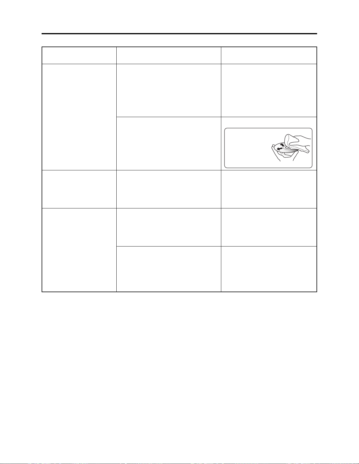
Troubleshooting > Messages and Troubleshooting
Message
Cause/condition for
Troubleshooting
message to appear
Control Information Error.
COPY PROTECT
Data error in a part of image
file.
Repair disc now?
YES NO
*3: Take care with the following when repairing video file:
a) If the disc is removed while it is being recognized, the repair function of video file will be invalid.
b) If the timing when power is turned off is inappropriate, normal repair may be impossible.
c) If the disc has data that was recorded on a device other than this DVD video camera/recorder, normal
repair may be impossible.
d) The repaired data may be different from the original recorded content because of partial deletion of a
defective portion.
e) The repaired data (only corrected portion in case of partial repair) will lose the original date/time
information because the information for date/time when repair was executed will be added.
f) If “all repair” is executed, repair will be made in the order of all videos and all photos, and the time-
sequential relationship of recorded contents may be lost.
Appears if mismatch has occurred
between the recorded video and the
scene information because editing was
performed near the limit of disc storage
capacity on a device other than the DVD
video camera/recorder; it also appears if
the control information file was operated.
Also appears when reading or writing
from/to recorded file cannot be performed
because the disc is dirty.
Appears if an attempt is made to record
copy-guarded image. The specifications
state that copy-guarded image cannot be
recorded on the DVD video camera/
recorder.
Appears if writing to file cannot be
completed normally because power was
turned off by mistake during video
recording or editing, and an abnormality
in part of the file is recognized.
Also appears when condensation occurs
on lens or drive of the DVD video
camera/recorder. Condensation will occur
when the DVD video camera/recorder is
moved from a cold place to a warm place.
Update the control information.
(Start Disc Navigation, press the
MENU button, and then execute
“Update Control Info.” in the “Disc”
menu.
Clean the disc, or replace it.
Disc cleaning method:
Use soft cloth to clean
from inner to outer
circumference in
axial direction.
[Never use solvent.]
Stop trying to record.
Choose “YES” and designate partial
repair (automatic repair) of video file.
Choosing “NO” will display a
message for verifying initialization.
Do not execute repair, but set the
power switch to “POWER OFF” with
the disc loaded, and then leave the
DVD video camera/recorder in a dry
place until condensation disappears
(usually 1-2 hours).
(*3)
4 - 11

Troubleshooting > Messages and Troubleshooting
Message
Data error in all image file.
Repair all data now?
YES NO
DISC ××××
(4-digit alpha-numerals
showing the code of trouble
will appear in ××××.)
DISC ACCESS
DISC ALMOST FULL
Disc error
Disc error has occurred.
Finalizing is not complete.
Cause/condition for
message to appear
Appears if writing to file cannot be
completed normally because power was
turned off by mistake during video
recording or editing, and it is recognized
that the video file must be totally
repaired.
Also appears when condensation occurs
on lens or drive of the DVD video
camera/recorder. Condensation will occur
when the DVD video camera/recorder is
moved form a cold place to a warm place.
Appears if the self-diagnosis function in
the DVD video camera/recorder detects a
serious problem.
This message appears during normal
operation process, when the DVD video
camera/recorder checks whether a proper
disc has been loaded or not. It is
displayed for a longer time period when
the date has changed.
This message appears during normal
operation process, when the recorded
images are being stored on disc.
Appears if the remaining video
recordable time on disc is less than 10
minutes, or the remaining number of
recordable photos is less than 10.
Appears when the disc has been edited
on a device other than the DVD video
camera/recorder, and mismatch has
occurred in recorded data.
Also appears when reading or writing
from/to recorded file cannot be performed
because the disc is dirty.
Appears when the disc could not be
finalized because it was dirty.
Appears if accident, such as power off,
has occurred during finalizing.
If the message still appears even when
the disc has been cleaned and finalized
again and again, the disc may be
defective.
Troubleshooting
Choose “YES” and designate total
repair (automatic repair) of video file.
Choosing “NO” will display a message
for verifying initialization.
[Refer to *3 page 4-11]
Do not execute repair, but set the
power switch to “POWER OFF” with
the disc loaded, and then leave the
DVD video camera/recorder in a dry
place until condensation disappears
(usually 1-2 hours).
Take note of the 4-digit alphanumerals in ××××, and refer to “4-4
Self-Diagnosis Function and
Troubelshooting”.
Operate the DVD video camera/
recorder after the message
disappears.
Operate the DVD video camera/
recorder after the message
disappears.
Delete unnecessary scenes, or replace
the disc.
Format the disc (deleting all recorded
data), or replace the disc.
Clean the disc, or replace it.
[Refer to page 4-11]
Clean the disc, or replace it.
[Refer to page 4-11]
Set the power switch to “POWER
OFF” and reconnect the AC adapter/
charger; then set the power switch to
“VIDEO” and start finalizing again.
Or press the DISC EJECT button,
reload the disc, and then execute
finalizing.
Replace the disc.
4 - 12

Troubleshooting > Messages and Troubleshooting
Message
Disc error has occurred.
Format the disc now?
YES NO
Disc error has occurred.
Formatting is not complete.
Disc error has occurred.
Keep disc inside & restart.
Disc full.
Cannot execute.
Disc has no data.
Disc has no PlayList.
Disc includes protected
scenes.
Delete scenes?
YES NO
Cause/condition for
message to appear
Appears when a DVD-RAM disc
initialized on PC, etc., or a card whose
initialization was suspended before, is
loaded.
Appears when the disc could not be
normally formatted because it was dirty.
Also appears when a warped or distorted
disc was loaded, or a logically damaged
disc whose formatting was suspended is
loaded.
Appears if a problem has occurred during
editing of video file.
Appears if the recording capacity of disc
has reached the limit during editing of
video file.
Appears when the MANU button or
playback button was pressed with no
scene recorded.
Appears if switching of play list is
selected with no play list registered.
Appears if the loaded disc has a program
(scene) that is write-protected by the
software write-protect function, which is
effective in program units. Although the
DVD video camera/recorder is equipped
with a software disc-protect function that
is effective for disc units, it does not
comply with software write-protect for
program units. (The DVD Forum defines
two types of software protect for DVDRAM disc: disc units and program units.)
Troubleshooting
Choose “YES” and designate it to
initialize the DVD-RAM disc
(deleting all recorded data).
Clean the disc, or replace it.
[Refer to page 4-11]
Replace the disc.
Exit the Disc Navigation function and
set the power switch to “POWER
OFF” with the disc loaded; then
reconnect the AC adapter/charger
and set the power switch to “VIDEO”
or “PHOTO (disc)”. (The DVD video
camera/recorder will automatically
repair the video file.)
Delete unnecessary scenes, or replace
the disc.
Operate the DVD video camera/
recorder after the message
disappears.
Operate the DVD video camera/
recorder after the message
disappears.
Release the write-protect using the
device that has the software writeprotect function for program units, or
choose “YES” and designate it to
delete the scenes.
Disc is full.
Cannot add control info.
Appears if the number of scenes on play
list exceeds the upper limit (999) while
control information is being added.
[Refer to *1 page 4-9]
4 - 13
Delete any unnecessary scenes, or
combine several scenes, and then
operate the DVD video camera/
recorder.

Troubleshooting > Messages and Troubleshooting
Message
Cause/condition for
Troubleshooting
message to appear
Disc is not formatted.
Format the disc now?
YES NO
Disc is not formatted.
If it formats, it becomes
possible to use for camera.
However, when you record
from PC connection
terminal, please do not
format.
Format the disc now?
YES NO
Disc overheat.
Please retry later.
DPOF is not set to scene
DPOF scenes over limit.
Cannot set DPOF scenes.
DVD-R Disc, Video mode
cannot be changed.
END OF DISC
End scene cannot be divided.
*4: The purpose of formatting DVD-R disc on the DVD video camera/recorder is to write to disc a program
exclusively for camera recording that is necessary to record images shot by camera in real time
(increasing the response from disc). When recording images that were edited using PC on DVD-R disc via
the PC connection terminal, do not format the disc: The program used exclusively for camera recording
will disable normal recording.
Appears when an unformatted DVDRAM disc or one initialized (other
UDF2.0) on PC is loaded.
Also appears if user rejects partial repair
or total repair of video file.
Appears when a brand-new DVD-R disc
was loaded.
Appears when the temperature inside
the DVD video camera/recorder, or the
temperature of disc, is too high, and
normal operation cannot be executed.
Appears if “Slide Show: DPOF” is
specified when a card for which DPOF
has not been set is loaded.
Appears when the number of settable
scenes for DPOF has exceeded 999.
Appears if an attempt is made to change
the Video recording mode of a recorded
DVD-R disc. Once even one scene is
recorded on a DVD-R disc which has
been initialized, the originally
designated Video recording mode is
specified to be maintained until the final
recording on the disc.
Also appears after the DVD-R disc has
been initialized.
Appears if the disc recordable capacity
has reached the limit during recording.
Appears when the last image of scene
was selected to divide the scene: The
specifications state that dividing a scene
at its end is not possible.
When initializing it (deleting all
recorded data), choose “YES” and
designate it.
Choose “NO” and designate partial
repair or total repair. When
initializing it (deleting all recorded
data), choose “YES” and designate it.
When recording on the DVD video
camera/recorder, choose “YES” and
designate it. When recording video
edited on PC connected via the PC
connection terminal, choose “NO” and
designate it.
Set the power switch to “POWER
OFF” with the disc loaded, and then
leave the DVD video camera/recorder
in a well-ventilated place until the
inside temperature decreases.
Specify “Slide Show: All”, or do not
try slide show.
Release unnecessary DOPF setting
on photos when newly setting DPOF.
Stop trying to change the Video
recording mode, or replace the disc.
Operate the DVD video camera/
recorder after the message
disappears.
Replace the disc.
Stop trying to divide a scene.
(*4)
4 - 14

Troubleshooting > Messages and Troubleshooting
Message
Error has occurred.
Error code No. ××××
Please read the manual.
(4-digit alpha-numerals
showing the code of trouble
will appear in ××××.)
Error has occurred.
Please reinsert a disc.
Error has occurred.
Please restart.
Error occurred.
Please replace disc or format
disc
Error occurred.
Please replace disc.
ERROR ××××
(4-digit alpha-numerals
showing the code of trouble
will appear in ××××.)
Finalize may not be
complete.
Finalize again now?
YES NO
Found error in image file.
Repair disc now?
YES NO
It is unrecordable on this
card.
Cause/condition for
message to appear
Appears if the self-diagnosis function of
the DVD video camera/recorder has
detected a serious problem when power
was turned on, or the same trouble
occurred three consecutive times in
modes other than recording.
Appears if, when power was turned on,
the self-diagnosis function of the DVD
video camera/recorder detected a slight
trouble that can be fixed: See “4-4 SelfDiagnosis Function and
Troubleshooting” for details.
Appears if, when power was turned on,
the self-diagnosis function of the DVD
video camera/recorder detected a slight
trouble that can be fixed by turning
power on again: See “4-4 Self-Diagnosis
Function and Troubleshooting” for
details.
Appears if repair has failed with DVDRAM disc after message “Data error in
all image file. Repair all data now?” or
“Found error in image file. Repair data
now?” appeared.
Appears if repair has failed with DVD-R
disc after message “Data error in all
image file. Repair all data now?” or
“Found error in image file. Repair data
now?” appeared.
Appears if the self-diagnosis function in
the DVD video camera/recorder detects a
serious problem during recording, or
when the same trouble occurs three
times consecutively during recording.
Appears if accident, such as power off,
occurred during finalizing, and then
power was turned on again or disc was
reloaded.
Appears if repair has failed after
message “Data error in a part of image
file. Repair disc now?” appeared.
Appears when a card other than SD
memory card or MultiMediaCard was
loaded.
Troubleshooting
Take note of the 4-digit alphanumerals in ××××, and refer to “4-4
Self-Diagnosis Function and
Remedy”.
Set the power switch to “POWER
OFF”, press the DISC EJECT button,
and then reinsert the disc. After that,
set the power switch to “VIDEO” or
“PHOTO (disc)”.
Set the power switch to “POWER
OFF”, reconnect the AC adapter/
charger or battery, and then set the
power switch to “VIDEO” or “PHOTO
(disc)”.
Initialize the disc (deleting all
recorded data), or replace the disc.
Replace the disc.
Take note of the 4-digit alphanumerals in ××××, and refer to “4-4
Self-Diagnosis Function and
Troubelshooting”.
Choose “YES” and designate it to
finalize the disc.
Choose “YES” and designate total
repair (automatic repair) of video file.
Choosing “NO” will display a message
for verifying initialization. [Refer to
*3 on page 4-11]
Insert an SD memory card or
MultiMediaCard.
4 - 15

Troubleshooting > Messages and Troubleshooting
Message
JPEG file related to scenes
are not found.
No card
No card. Please insert card.
NO DISC
No more scenes.
Play List was deleted.
Play Lists over limit.
Same scenes on PlayList will
be deleted.
Delete scenes?
YES NO
Scenes over limit.
Cannot add scenes.
Scenes over limit.
Cannot divide scenes.
Cause/condition for
message to appear
Appears when an attempt is made to
copy photos on disc to card, when photo
(JPEG) file to be copied is not stored on
disc. When the DVD video camera/
recorder records a photo on disc, two
photo files will be stored on disc - a photo
(conforming to DVD video recording
format) file to be displayed on the DVD
video camera/recorder, and a photo
(JPEG) file for storage that is linked to
the photo for display. This message will
appear when only the photo file for
storage has been deleted on PC, etc.
Appears when no card is loaded.
Appears when recording photos on card
was attempted with no card loaded.
Appears if no disc is loaded.
If the message appears even when a disc
is loaded, condensation might have
occurred on lens or drive of the DVD
video camera/recorder.
Appears during user operation; all
recorded scenes have been deleted and
cleared. The specifications stipulate that
a play list with no scene on it cannot be
held: If all registered scenes have been
deleted, the play list will also be deleted.
Appears if an attempt is made to create a
new play list or edit play list after the
number of registered play lists has
reached the upper limit (99) that is
defined by the DVD video recording
format.
This message appears during user
operation, if even one play list has been
created during scene deletion. This
message does not appear when a scene is
deleted from play list.
Appears if an attempt is made to register
a new scene in play list, with the
specified 999 upper limit scenes
registered. [Refer to *1 page 4-9]
Appears if an attempt is made to divide a
scene with the specified 999 upper limit
scenes registered, or the number of
scenes will exceed 999 with division.
[Refer to *1 page 4-9]
Troubleshooting
Copy photos to card via PC. The
photo (JPEG) file for storage is stored
in DCIM\100HPNX1 folder.
Insert a card.
Insert a card.
Load a disc
Set the power switch to “POWER
OFF” with the disc loaded, and then
leave the DVD video camera/recorder
in a dry place until condensation
disappears (usually 1-2 hours).
Operate the DVD video camera/
recorder after the message
disappears.
Delete unnecessary scenes before
creating a new play list or editing
play list.
Choose “YES” and designate it to
delete selected scenes.
Delete unnecessary scenes from play
list before adding a new scene to it.
Delete unnecessary scenes before
dividing a scene.
4 - 16

Troubleshooting > Messages and Troubleshooting
Message
Scenes over limit.
Cannot move scenes.
Stop processing.
There was no scene which
can be deleted.
This card cannot be used.
Please replace card.
This disc cannot be used.
Please replace disc.
This disc is recorded by the
NTSC system.
Please replace disc.
Top scenes cannot be
divided.
UNFORMAT DISC
Use AC adapter/charger.
Cause/condition for
message to appear
Appears if an attempt is made to move a
scene at the upper limit of 999 scenes
registered, or the number of scenes will
exceed 999 by moving a scene. [Refer to
*1 page 4-9]
This message appears during operation
process. It will appear when user
interrupted any process by pressing the
stop/cancel button when processing
multiple scenes, etc.
Appears when only multiple locked
scenes were selected using the Disc
Navigation function, and deleting them
was attempted.
Appears when a card other than SD
memory card or MultiMediaCard was
loaded.
Appears when a type of disc that cannot
be used on the DVD video camera/
recorder was loaded.
Appears when a disc recorded in the
NTSC system was loaded: This DVD
video camera/recorder is exclusively for
the PAL system and does not comply
with the NTSC system.
Appears when the first image of scene
was selected to divide the scene: The
specifications state that dividing a scene
at its top is not possible.
Appears when an unformatted or
logically damaged disc was loaded.
Also appears when a dirty disc was
loaded.
If the message appears when a normal,
formatted disc has been loaded,
condensation might have occurred on the
lens or drive of the DVD video camera/
recorder. Condensation will occur when
the DVD video camera/recorder is moved
from a cold place to a warm place.
Appears if a battery is used when
finalizing a DVD-R disc. The
specifications state that DVD-R disc can
be finalized only when the AC adapter/
charger powers the DVD video camera/
recorder.
Troubleshooting
Delete unnecessary scenes before
moving scenes.
Operate the DVD video camera/
recorder after the message
disappears.
Use the Disc Navigation function to
unlock the scenes, and then restart
operation.
Insert an SD memory card or
MultiMediaCard.
Check the type of disc and insert a
disc usable on the DVD video camera/
recorder.
Use a disc recorded in the PAL
system.
Stop trying to divide a scene.
Format the disc (deleting all recorded
data), or replace the disc.
Clean the disc, or replace it.
[Refer to page 4-11]
Set the power switch to “POWER
OFF” with the disc loaded, and then
leave the DVD video camera/recorder
in a dry place until condensation
disappears (usually 1-2 hours).
Terminate the Disc Navigation
function, set the power switch to
“POWER OFF” with the disc loaded,
remove the battery, and then connect
the AC adapter/charger: Finalize the
disc again.
4 - 17

Troubleshooting > Messages and Troubleshooting
Message
Cause/condition for
Troubleshooting
message to appear
Use AC adapter/charger.
Turn off power.
VIDEO scene cannot be
copied to card.
Write protected.
Check disc.
Write-protected.
Check card.
Appears if a battery is used when
repairing video files. The specifications
state that video files can be repaired only
when the AC adapter/charger powers the
DVD video camera/recorder.
Appears if an attempt is made to copy
video to card. The specifications state
that no video is unrecordable on card.
Appears if a DVD-RAM disc that was
write-protected for disc units by software
disc-protect function is loaded, or if an
attempt is made to record on writeprotected disc.
Appears when an SD memory card
whose erasure prevention switch was
locked is loaded.
Set the power switch to “POWER
OFF” with the disc loaded, remove
the battery, and then connect the AC
adapter/charger.
[Refer to *3 page 4-11]
Stop trying to copy a video, or select
photos and execute copy.
Release the software disc-protect.
Unlock the erasure prevention switch
of SD memory card.
Note:
The listed messages are subject to change without notice for improvement of performance.
4 - 18

Troubleshooting > Self-Diagnosis Function and Troubleshooting
4-4 Self-Diagnosis Function and Troubleshooting
Restriction:
The information included in this section is exclusively for service personnel. Do not disclose it to
persons other than service engineers.
This DVD video camera/recorder is equipped with a self-diagnosis function: If it detects a problem
when power is turned on or during operation, it will display a message, replace the content of
problem with an error code (4-digit alphanumeric characters), and then store it in flash memory.
4-4-1 Message displayed by self-diagnosis function
There are two types of message displayed when the self-diagnosis function detects problems:
messages for minor problems, and messages for serious problems.
Information:
The messages of self-diagnosis function will be displayed until the power switch is set to “POWER
OFF” or the disc is removed, regardless of whether there is a minor or serious problem.
(1) Messages for minor problems
These messages appear when troubleshooting is likely
possible for the problem detected when power was turned
on, following the procedure below.
Procedure when message shown in Fig. 4-4-1 appears:
Set the power switch to “POWER OFF”, reconnect the AC
adapter/charger or battery, and then set the power
switch to “VIDEO” or “PHOTO (disc)”.
Procedure when message shown in Fig. 4-4-2 appears:
Set the power switch to “POWER OFF”, press the DISC
EJECT button, and then reinsert the disc. After that, set
the power switch to “VIDEO” or “PHOTO (disc)”.
If the problem is handled by the procedure shown above,
servicing is not necessary in almost all cases. However, if
the DVD video camera/recorder cannot be restored from the
problem or the same problem recurs, appropriate servicing
will be required.
The information on minor problems will be stored in flash
memory as error codes (4-digit alphanumeric characters),
whether or not the DVD video camera/recorder is restored
from the problems. See “4-4-2 Error codes stored in flash
memory” for how to display the stored error codes.
Error has occurred.
!
Please restart.
Fig. 4-4-1 Message (1/2)
Error has occurred.
!
Please reinsert a disc.
Fig. 4-4-2 Message (2/2)
4 - 19

Troubleshooting > Self-Diagnosis Function and Troubleshooting
(2) Messages for serious problems
These messages appear when solving the problem detected
when power is turned on or during operation is not likely by
turning power on again or reloading the disc: Error codes
(4-digit alphanumeric characters) will directly appear, and
similar messages will appear if a problem from the same
cause occurs three times consecutively during operation.
If messages for serious problems appear, perform
troubleshooting according to “4-4-3 Major error codes and
troubleshooting”.
The error codes appearing with messages will be stored in
flash memory. See “4-4-2 Error codes stored in flash
memory” for how to display the stored error codes.
Error has occurred.
!
Error code No. 1100
Please read the manual.
Fig. 4-4-3 Example of Message
(displayed in modes other than during
power on or recording)
ERROR : 1100
Fig. 4-4-4 Example of Message
(displayed during recording)
4 - 20

Troubleshooting > Self-Diagnosis Function and Troubleshooting
4-4-2 Error codes stored in flash memory
(1) Displaying error codes and clearing them
Display method
1) Connect the battery or AC adapter/charger, and then set
the power switch to “VIDEO”.
2) Display the error using the following button operation:
Press the SELECT button and release it; then, within 0.5
second, simultaneously hold down the SELECT and
FOCUS buttons for at least 3 seconds.
Display clearing method
1) Press the DISPLAY button.
After displaying and checking error code, be sure to clear
the error code display: If you neglect this, the error code
will always be displayed.
(2) Details of error code display
1) Error codes of 2 problems are displayed one above the
other.
The error code of the latest problem appears in the upper
row, and the error code of the problem that occurred
before appears in the lower row. However, when the
same problem occurs continuously, it will be judged as
one problem, and the same error code will not appear
continuously.
2) If only one error code is stored in flash memory, the error
code will appear in the upper row, and “0000” will appear
in the lower row.
3) If no error code is stored in flash memory, “0000” will
appear in both rows.
Error codes
1100
0400
Fig. 4-4-5 Example of Error Code
Display
4 - 21

Troubleshooting > Self-Diagnosis Function and Troubleshooting
4-4-3 Major error codes and troubleshooting
Table 4-4-1 shows the error codes that are likely to frequently appear, and troubleshooting when
they appear.
If error codes other than those listed in Table 4-4-1 appear, check with the factory for
troubleshooting.
Table 4-4-1 Major Error Codes and Troubleshooting
Error code
0400
1100
10AE
10AF
0280
2881
Recognition of disc failed.
Reading of data from disc failed.
Disc physically damaged, i.g.,
scratched or distorted.
The optical pickup in disc drive unit
failed to move.
Recognition of disc failed. [This
message is likely to appear frequently
when the ambient temperature is too
low (0°C or less)].
Contents of problem
Troubleshooting
1) Set the power switch to “POWER OFF”, reattach the
battery or AC adapter/charger, and then set the power
switch to “VIDEO” or “PHOTO” (disc).
Take care not to subject the DVD video camera/
recorder to impact or vibrations at this time.
2) Set the power switch to “POWER OFF”, remove the
disc and check whether or not it is dirty, scratched or
distorted. If it is dirty, clean it referring to the next
page, and then reload it. If it is scratched or distorted,
use another disc.
Then set the power switch to “VIDEO” or “PHOTO”
(disc).
3) Replace the disc without regard as to whether it is
dirty, scratched or distorted.
Replace the disc.
1) Check the ambient temperature.
2) Set the power switch to “POWER OFF”, remove the
disc and check whether or not it is dirty, scratched or
distorted. If it is dirty, clean it, and then reload it. If it
is scratched or distorted, replace the disc.
Then set the power switch to “VIDEO” or “PHOTO”
(disc).
Disc cleaning method:
Use soft cloth to clean
from inner to outer
circumference in
axial direction.
[Never use solvent.]
3) Check to see whether or not condensation has
occurred. If condensation has occurred, set the power
switch to “POWER OFF” with the disc loaded, and
then leave the DVD video camera/recorder in a dry
place for 1-2 hours.
4) Replace the disc.
4 - 22

Troubleshooting > Self-Diagnosis Function and Troubleshooting
Error code Contents of problem Troubleshooting
3122
3126
3133
7601
7890
7791
3105
E000
EC87
F100
F526
F571
F572
F573
F600
F700
F924
FB24
FB34
FB44
Recording on DVD-RAM disc failed.
Writing data file to disc failed.
It takes much more time than
necessary to process start or end of
recording (timeout error).
Recording on DVD-R disc failed.
Formatting DVD-RAM disc failed.
When recording photo, writing data to
disc failed.
Writing data to disc failed.
Abnormal stop during reading or
writing of data from/to disc.
Buffer has overflowed during
recording.
When starting recording, reading of
data file on disc failed.
When recording photo, writing data to
disc failed.
When recording video, writing data to
disc failed.
Backup error
No response from disc drive even when
3 minutes has elapsed (drive timeout
error).
Recording failed
Initialization at start of recording
failed.
While recording mode was being
transferred to recording pause, writing
data to disc failed.
During processing of buffer overflow
error, writing data to disc failed.
1) Set the power switch to “POWER OFF”, reattach the
battery or AC adapter/charger, and then set the power
switch to “VIDEO” or “PHOTO” (disc).
Take care not to subject the DVD video camera/
recorder to impact or vibrations at this time.
2) Set the power switch to “POWER OFF”, remove the
disc and check whether or not it is dirty, scratched or
distorted. If it is dirty, clean it referring to the next
page, and then reload it. If it is scratched or distorted,
use another disc.
Then set the power switch to “VIDEO” or “PHOTO”
(disc).
3) Replace the disc without regard as to whether it is
dirty, scratched or distorted.
Format it again, or replace the disc.
1) Set the power switch to “POWER OFF”, reattach the
battery or AC adapter/charger, and then set the power
switch to “VIDEO” or “PHOTO” (disc).
Take care not to subject the DVD video camera/
recorder to impact or vibrations at this time.
2) Set the power switch to “POWER OFF”, remove the
disc and check whether or not it is dirty, scratched or
distorted. If it is dirty, clean it, and then reload it. If it
is scratched or distorted, replace the disc.
Then set the power switch to “VIDEO” or “PHOTO”
(disc).
3) When using DVD-R disc:
Replace the disc without regard as to whether it is
dirty, scratched or distorted.
When using DVD-RAM disc:
Initialize the disc (deleting all data recorded on
disc), or replace the disc.
4 - 23

Troubleshooting > System Resetting/Resetting Camera Functions
4-5 System Resetting/Resetting Camera Functions
This DVD video camera/recorder has two types of reset function: “System reset” and “Resetting
camera functions”.
The reset operation will return the various settings to the defaults when the DVD video camera/
recorder was shipped from factory.
Information:
If a defect occurs in product, take note of settings, and then execute system reset: The defect may
disappear.
4-5-1 List of items to be reset
Table 4-5-1 shows the items that will be reset to defaults at the factory by the two types of reset
operation: “system reset” and “resetting camera functions”.
Use the memo column provided in the table to enter the settings of any received device.
(1) Procedure for checking settings
1) Connect the battery or the AC adapter/charger.
2) Set the QUICK MODE switch to “OFF”.
3) Insert a DVD-RAM disc, and then set the power switch to “VIDEO”. For subsequent steps,
operate the DVD video camera/recorder while viewing the LCD monitor or viewfinder.
4) Press the MENU button to display the camera function setup menu screen: Make sure of the
settings.
5) Operate the joystick to display the menu screens for record function setup, date function setup,
LCD monitor setup and initial setup in sequence, making sure of the settings.
At this time, the items on photo quality, external photo input and self-timer will not appear, since
they are related to photo recording: Check them in steps 6) and 7).
6) Set the power switch to “[CARD]PHOTO”. It is not necessary to insert a card at this time.
7) Press the MENU button to display the camera function setup menu screen, and then operate the
joystick to display the record function setup menu screen in order to check the settings on photo
quality, external photo input and self-timer.
8) After checking is complete, press the MENU button to restore the ordinary screen.
4 - 24

Troubleshooting > System Resetting/Resetting Camera Functions
Table 4-5-1 List of items to be reset
Camera
Item
System
reset
function
reset
Default at
factory
Setting range
Camera Functions Setup
Program AE
White Bal.
EIS
Dig. Zoom
MIC Filter
16:9
Yes
Yes
Yes
Yes
Yes
Yes
Yes
Yes
Yes
Yes
Yes
Yes
Auto
Auto
On
40×
Off
Off
Auto, Sports, Portrait,
Spotlight, Sand & Snow,
Low Light
Auto, Set, Outdoor,
Indoor
On, Off
DZ-MV580E:
240×, 40×, Off
DZ-MV550E:
500×, 40×, Off
On, Off
On, Off
Record Functions Setup
VIDEO Mode
Quality
Input Source
PHOTO Input
Self Timer
OSD Output
Yes
Yes
Yes
Yes
Yes
Yes
Yes
Yes
Yes
Yes
Yes
Yes
FINE
FINE
CAMERA
Field
Off
On
With DVD-RAM disc:
XTRA, FINE, STD
With DVD-R disc:
FINE, STD
FINE, NORM, ECO
CAMERA, LINE
Frame, Field
On, Off
On, Off
Date Setup
Date Mode
Date Set
*1: The line input function is provided in the following models:
The symbols in parentheses ( ) in the above model names show the destinations and are displayed only
on packing box.
Refer to “2-5 Differences in Rating Labels and Difference in Function” when checking the body of DVD
video camera/recorder, to judge whether or not it is equipped with the line input function (destination).
Yes
Yes
DZ-MV580E(AU)/MV580E(SW)/MV580E(SWH)
DZ-MV550E(AU)/MV550E(SW)/MV550E(SWH)
Yes
No
D/M/Y
1/1/2004
0:00
17:00 D/M/Y,
5:00PM M/D/Y,
PM5:00 Y/M/D
-----------------
Yes: Will be reset
No: Will not be reset
Remarks
Low Light will not
appear when “VIDEO
mode: STD” is
specified.
Displayed on DZMV580E only in the
Video mode
Displayed only in the
Video mode
Displayed only in the
Video mode
Displayed only in the
card photo mode
Displayed only on
models that have the
line input function
Displayed only when
“Input Source:
CAMERA” is specified
(*1)
Memo
4 - 25

Troubleshooting > System Resetting/Resetting Camera Functions
Camera
Item
Brightness
Color Level
Beep
Power Save
Record LED
Language
Demo Mode
System
reset
Yes
Yes
Yes
Yes
Yes
Yes
Yes
function
reset
Yes
Yes
Yes
Yes
Yes
Yes
Yes
Default at
factory
Center
Center
On
Off
On
English
Auto
4-5-2 System reset procedure
1) Set the power switch to “POWER OFF”, and
then disconnect the battery or AC adapter/
charger.
2) Use a fine tipped pen, etc. to hold down the
RESET button for approx. 2 seconds.
Setting range Remarks Memo
LCD Setup
+
+
Initial Setup
On, Off
On, Off
On, Off
English, French, Spanish,
German, Italian
Auto, Off, Start
RESET
Fig. 4-5-1
4-5-3 Procedure for resetting camera functions
1) Connect the battery or AC adapter/charger.
2) Set the power switch to “VIDEO” and place the DVD video camera/recorder in the recording
pause status; loading disc is not necessary at this time. For the following steps, operate the DVD
video camera/recorder while viewing the LCD monitor or viewfinder.
3) Set the quick mode switch to “OFF”.
4) Press the MENU button to display the camera setting menu screen.
5) Use the joystick to choose “Initial Setup”, and then press the center of joystick.
6) Use the joystick to choose “Reset”, and then press the center of joystick: The screen for verifying
reset will appear.
7) Use the joystick to choose “YES”, and then press the center of joystick: Reset will be executed.
8) After reset, press the MENU button to close the camera setting menu.
4 - 26

Troubleshooting > Checking Versions of Firmware and Updating
4-6 Checking Versions of Firmware and Updating
This DVD video camera/recorder stores the 4 types of firmware shown in Table 4-6-1 in flash
memory.
These firmware programs will be updated whenever necessary to improve the performance of this
DVD video camera/recorder.
Check to see whether any defects in this DVD video camera/recorder can be eliminated by updating
any firmware programs: If improvement is likely, update them.
Information:
If any corrections in firmware are made at the factory, the information on how to obtain the
firmware data and create a disc or card containing upgraded firmware will be reported on service
bulletin, etc.
Table 4-6-1 List of Firmware Programs
Type of firmware
System firmware
Camera microprocessor
firmware
Drive main firmware
Drive core firmware
Software that drives SH CPU: Controls the operation of
entire system, including recording, playback, Disc
Navigation, connections with external device
Controls the operation of camera block (including optical
system), clock, battery, input/output
These programs control the DVD disc drive system
(mechanism block)
Description
Remarks
Does not require
updating
4-6-1 Checking firmware versions
(1) Purpose
When checking whether updating firmware is needed or not, use the following procedure to view
the version display screen (see Fig. 4-6-1) and check the version number.
Only the titles at top left of screens will be different when no disc is loaded or disc is loaded; the
other display contents will be the same.
(2) Version display/clear method
Display method
1) Connect the battery or AC adapter/charger.
2) Set the power switch to “VIDEO”. Operate the DVD video camera/recorder while viewing the
LCD screen or viewfinder from this point.
3) When a disc is loaded, press the DISC NAVIGATION button to display the thumbnail display
screen: This step is not necessary if no disc is loaded.
4) Operate the following buttons to view the version display screen:
Tilt the joystick up and hold it, then simultaneously press the SELECT button and REC buttons.
Display clearing method
1) Press the stop/cancel button to restore the thumbnail display screen. To return to the normal
screen, press the DISC NAVIGATION button.
4 - 27

Troubleshooting > Checking Versions of Firmware and Updating
(3) Details of version display screens
Table 4-6-2
Item
Model
System Ver.
Date
Cam Ver.
Drive (Main)
Drive (Core)
Model name
Version number of system firmware
Date/time when system firmware was created
Version number of Camera microprocessor
firmware
Version number of drive main firmware
Version number of drive core firmware
Information:
Display ×××× on subsequent screen shows the numbers or
alphabets.
Display contents
When no disc is loaded
Detail
Model: DZ-MV5-PAL
System: Ver. x.xx
Date: xxxx/xx/xx xx:xx:xx
Cam: Ver. x.xx
Drive (Main): xxxx.xx.xx. REV
Drive (Core): xxxx.xx.xx. REV
RETURN
When disc is loaded
Version
Model: DZ-MV5-PAL
System: Ver. x.xx
Date: xxxx/xx/xx xx:xx:xx
Cam: Ver. x.xx
Drive (Main): xxxx.xx.xx. REV
Drive (Core): xxxx.xx.xx. REV
RETURN
4-6-2 Updating firmware
(1) Purpose
If you receive information from the factory that updating
firmware is needed, you should do it to improve the
performance, functions and operability of the DVD video
camera/recorder.
Fig. 4-6-1
4 - 28

Troubleshooting > Checking Versions of Firmware and Updating
(2) Procedure for updating
1) Acquire the data for updating of firmware and create a disc or card for updating. Information on
how to obtain the firmware data and create a disc/card containing upgraded firmware will be
reported on service bulletin, etc.
2) Set the power switch to “POWER OFF”, and then use the AC adapter/charger to power the DVD
video camera/recorder. A battery cannot be used because it may interrupt power of the DVD
video camera/recorder during work.
3) Insert the disc/card for updating firmware.
4) Set the power switch to “POWER OFF” when using a disc for updating, or to “[CARD]PHOTO”
when using a card for updating.
5) After approx. 20 seconds, the updating start screen (Fig. 4-6-2) will appear, and the firmware
programs will be automatically updated thereafter. During updating, the screens showing that
designated firmware program is being updated will appear, followed by the screen showing that
updating is complete.
However, not all firmware programs need updating every time: The same version screen will
appear for firmware programs that do not require updating.
6) When all required updating is complete, the screen for verifying the version of updated firmware
will appear, and the updated firmware will be displayed in red.
7) To complete updating, set the power switch to “POWER OFF”, and then remove the disc/card for
updating.
Updating Start Screen System Update Screen Drive (Main) Update Screen
Firmware Update
Start Firmware update.
Drive (Core) Update Screen Updating Completed Screen Screen of Verifying the Version
Firmware Update
Updating drive (Core).
Please wait about 20 seconds.
Do not turn off power.
Same Version Screen
Firmware Update
Same revision.
Cannot update.
Firmware Update Firmware Update
Updating system.
Do not turn off power.
Firmware Update Firmware Update
Firmware updated.
Updating drive (Main).
Please wait about 2 minutes.
Do not turn off power.
Model: DZ-MV5-PAL
System: Ver. ×.××
Drive (Main): ××××.××.××.REV
Drive (Core): ××××.××.××.REV
Turn off power
Fig. 4-6-2
4 - 29

Troubleshooting > Trouble Diagnosis
4-7 Trouble Diagnosis
Information:
1) Use the DZ-ACS1 adapter/charger to power the DVD video camera/recorder for trouble
diagnosis.
2) The trouble diagnosis table was prepared presupposing that the circuit boards have been
normally attached and connected. Therefore, make sure beforehand that the circuit boards are
correctly connected, that connectors and cables are not damaged, and that the status of their
connections is correct.
Prohibition:
During trouble diagnosis, never look directly into the objective lens of optical pickup block in disc drive
unit, and take great care that the reflected laser beam does not enter your eye.
4-7-1 Trouble diagnosis table
Interpreting the trouble diagnosis table:
1) Search for the defective symptom. If there are multiple check points or multiple details of check
for one symptom, check the items from the top down.
2) Set this DVD video camera/recorder to a service position that matches the symptom. There are
four service positions (A)-(D) for this DVD video camera/recorder. Set to the appropriate service
position, referring to “Disassembly/reassembly to enable service position”.
If only dashes — are entered in the service position column, trouble diagnosis is possible without
disassembling this DVD video camera/recorder.
3) Connect the measurement terminals to the check points, and collate the results with the details
of check.
Letters in brackets [ ] that follow the check points show the name and side of circuit board.
Example: [MAN-A] shows that the check point exists on side A of MAN-H/MAN circuit board.
Information:
The MAN-H/MAN or AEL-H/AEL circuit board has some check points to which no terminals of
test equipment can be directly connected even when this DVD video camera/recorder is set to a
service position.
Solder a lead wire of approx. 10 cm to such check points, referring to “Disassembly/reassembly to
enable service position” and “circuit board diagrams”. When trouble diagnosis is complete, be sure
to remove the lead wire.
4) Perform troubleshooting according to the check results, referring to the troubleshooting columns.
4 - 30

Troubleshooting > Trouble Diagnosis
Symptom
Service
position
No power
Date/time is
incorrect
Auto-focus does
not operate.
No zoom works
even if zoom lever
is operated.
(A)
(B)
-----
-----
(A)
F0501 [MAN-B]
F0502 [MAN-B]
F0503 [MAN-B]
F0504 [MAN-B]
TL0504 [MAN-B]
IC1503- 53 to 56
[MAN-B] (Do not
solder lead wire)
TL0510 [MAN-A]
TL0511 [MAN-B]
TL0512 [MAN-A]
TL0513 [MAN-A]
TL0515 [MAN-A]
TL0517 [MAN-A]
TL0518 [MAN-B]
TL7041 [AEL-B]
TL1543 [MAN-B]
Table 4-7-1 Trouble Diagnosis Table
Check points
-----
-----
Detail of check
Is fuse blown?
Is the voltage approx. 3.2 V
DC (REG ON) when the
power switch is set to
"VIDEO" or "PHOTO" from
"POWER OFF"?
Can approx. 3 V DC (SYS3V)
be confirmed?
Can approx. 1.5 V DC
(C1.6V) be confirmed?
Can approx. 3.2 V DC
(CAM3V) be confirmed?
Can approx. 4.8 V DC
(CAM5V) be confirmed?
Can approx. 3 V DC (D3V)
be confirmed?
Can approx. 5 V DC (D5V)
be confirmed?
Can approx. 2.5 V DC
(D2.5V) be confirmed?
Can approx. 15 V DC (C15V)
be confirmed?
Can approx. 3 V DC (B/U3V)
be confirmed?
Even if manual focus is set
and +/- buttons are operated,
focus is not correct, and
when power is turned on
again, abnormal sound is
heard from the lens and it
takes more than 20 seconds
before an image appears.
No zoom is operated by the
remote control, and when
power is turned on again,
abnormal sound is heard
from the lens and it takes
more than 20 seconds before
an image appears.
Can change in voltage be
confirmed when lever is
operated (T/W)?
Troubleshooting due to
check results
Yes: Replace MAN-H/
MAN circuit board.
No: Replace MAN-H/
MAN circuit board.
Yes: Replace MAN-H/
MAN circuit board.
No: Replace BA1801.
Yes: Replace lens unit.
No: Replace MAN-H/
MAN circuit board.
Yes: Replace lens unit.
Yes: Replace MAN-H/
MAN circuit board.
No: Replace rear cover.
4 - 31

Troubleshooting > Trouble Diagnosis
Symptom
DISC EJECT
button does not
operate
REC button does
not operate
Left button/
joystick does not
operate
QUICK MODE
switch does not
operate
No image on LCD
monitor
No image in
viewfinder (EVF)
Block noise
appears during
video recording
Camera recorded
image is abnormal
No image from AV
input/output
terminal
Service
position
(A)
(B)
(C)
(C)
----(D)
(C)
Close LCD
monitor
-----
(B)
(B)
-----
(B)
Check points Detail of check
TL1547 [MAN-B]
TL0522 [MAN-A]
TL7030 [AEL-B]
TL7028 [AEL-B]
-----
TL3418 [LCD]
TL3715 [AEL-B]
-----
TL2084 [MAN-A]
TL2085 [MAN-A]
TL2086 [MAN-A]
TL2089 [MAN-A]
TL2090 [MAN-A]
TL2091 [MAN-A]
TL2095 [MAN-A]
TL2082 [MAN-A]
-----
TL6010 [MAN-B]
Can change in voltage be
confirmed when button is
operated (EJECT SW)?
Can change in voltage be
confirmed when button
(REC) is pressed?
Can change in voltage be
confirmed when button/
joystick (KEY1) is moved?}
Can change in voltage be
confirmed when switch
(KEY2) is moved?
Does backlight turn on?
Can approx. 5 V DC (INV5V)
be confirmed?
Can video signal (EVF-G) be
confirmed?
----------
Can sensor drive pulses (V14, H1, H2, RG) be confirmed?
Can video signal (CCD-OUT)
be confirmed?
Does image appear on LCD
monitor or in EVF?
Can video signal (VIDEO) be
confirmed?
Troubleshooting due to
check results
Yes: Replace MAN-H/
MAN circuit board.
No: Replace rear cover.
Yes: Replace MAN-H/
MAN circuit board.
No: Side case-L or parts
on the SWL2 circuit
board faulty.
Yes: Replace MAN-H/
MAN circuit board.
No: Replace SW8017 on
SWL3 circuit board.
Yes: Replace LCD unit.
Yes: Q3451 or Q3452
and its peripheral
circuits are faulty.
No: Replace MAN-H/
MAN circuit board.
Yes: Replace EVF unit.
No: Replace IC3701.
Replace MAN-H/MAN
circuit board.
No: Replace MAN-H/
MAN circuit board.
Yes: Replace MAN-H/
MAN circuit board.
No: With DZ-MV580E,
replace IC1001.
With DZ-MV550E,
replace lens unit.
No: Replace MAN-H/
MAN circuit board.
Yes: Replace MAN-H/
MAN circuit board.
No: IC6103 and its
peripheral circuits
are faulty.
4 - 32

Troubleshooting > Trouble Diagnosis
Symptom
No sound from
speaker
No audio from AV
input/output
terminal
Audio from builtin microphone
cannot be recorded
Audio from
external
microphone cannot
be recorded
When a darkish
scene is recorded,
a bright point will
appear on the
screen for external
output (CRT-type
color monitor
screen).
EIS does not work.
Service
position
(C)
(B)
(B)
(B)
(B)
-----
(B)
Check points Detail of check
TL1534 [MAN-B]
TL1535 [MAN-B]
TL6006 [MAN-B]
TL6009 [MAN-B]
IC6101-1, 7, 8, 14
[AEL-A]
(Do not solder lead
wire)
TL6101 [AEL-B]
TL6102 [AEL-B]
IC6201-3, 4
[AEL-A]
(Do not solder lead
wire)
-----
PG0154-1 [SHE]
PG0154-3 [SHE]
PG0154-2, 4
[SHE]
Can audio signal (SP_OUT+,
SP_OUT-) be confirmed?
Can audio signal (AUD-L,
AUD-R) be confirmed?
Can audio signal (MIC_INL,
MIC_INR) be confirmed?
Can audio signal (MIC_INL,
MIC_INR) be confirmed?
Can audio signal
(EXTMIC_LCH,
EXTMIC_RCH) be
confirmed?
This bright point will not
disappear even when "6-4-9
Spot Noise" is performed.
Can approx. 3.1 V DC (C3V)
be confirmed?
Can approx. 0 V DC
(GYRO_RST) be confirmed?
Can approx. 1.3 V DC be
confirmed when the camera
is fixed, and can variation in
voltage be confirmed when
the camera is shaken?
Troubleshooting due to
check results
Yes: Replace disc cover.
No: IC6103 and its
peripheral circuits
are faulty.
Yes: Replace MAN-H/
MAN circuit board.
No: IC6103 and its
peripheral circuits
are faulty.
No: Built-in
microphone, or
IC6101 and its
peripheral circuits
are faulty.
Yes: IC6201 or its
peripheral circuits
are faulty.
No: Q6101-6104,
Q6108, Q6109,
Q6207, Q6208 or
their peripheral
circuits are
faulty.
Yes: IC6201 or its
peripheral circuits
are faulty.
No: Replace MAN-H/
MAN circuit
board.
With DZ-MV580E,
replace IC1001.
With DZ-MV550E,
replace lens unit.
No: Replace MAN-H/
MAN circuit
board.
No: Replace MAN-H/
MAN circuit
board.
Yes: Replace MAN-H/
MAN circuit
board.
No: Replace IC1401,
IC1402 or IC1403.
4 - 33

Troubleshooting > Trouble Diagnosis
Symptom
Even if a normal
disc is inserted,
message "DISC
ACCESS"
continues to
appear, and the
disc is not
recognized.
Message "NO
DISC" appears
approx. 1 second
after a normal disc
is inserted.
Message "NO
DISC" appears
within 10 seconds
after a normal disc
is inserted.
Even when a disc
not protected is
inserted, message
"Write protected.
Check disc"
appears.
Even when a
formatted disc is
inserted, message
"Disc is not
formatted"
appears.
Service
position
-----
-----
-----
-----
-----
Check points Detail of check
-----
-----
-----
-----
-----
----------
----------
----------
----------
----------
Troubleshooting due to
check results
Replace disc drive unit.
If the DRF-H/DRF circuit
board is not damaged or
its connection status is
normal, replace disc drive
unit.
Replace disc drive unit.
Replace disc drive unit.
4 - 34

Troubleshooting > Trouble Diagnosis
4-7-2 Disassembly/reassembly to enable service position
Prohibition
Be sure to disconnect the AC adapter/charger or battery from the DVD video camera/recorder.
The DVD video camera/recorder has a built-in laser emitter block. Never look into it: If Laser beam
strikes your eye, it could cause serious vision damage.
Information:
Numbers in diagrams are step numbers for setting procedure. Letters in [ ] show the types of
screw. Letters in brackets ( ) show the name of parts.
(1) Setting to service position (A)
Service position (A) is mainly used for trouble
diagnosis of the power supply system and the
system of disc cover/operation buttons on side
case-R. Perform trouble diagnosis using the
check points on MAN-H/MAN circuit board.
LEAD
WIRES
Remove the MAN-H/MAN circuit board in
advance, referring to “5. Disassembly and
Reassembly”.
1) Solder a lead wire of approx. 10 cm to the
check points (except for IC pins) on side A of
MAN-H/MAN circuit board, referring to “4-71 Trouble diagnosis table” and “C-1 MAN-H/
MAN” circuit board diagram. (See Fig. 4-7-2)
MAN-H/MAN
CIRCUIT
BOARD
Fig. 4-7-1 Service Position (A)
MAN-H/MAN
TL0522
Ciruit Board (Side A)
TL2090 TL2085 TL2086 TL2082
TL2089 TL2091 TL2084 TL2095
: Check point (TL: Test land)
: Lead wire
Fig. 4-7-2 Lead wire soldering
LEAD
WIRES
TL0515
TL0512
TL0510
TL0513
TL0517
4 - 35
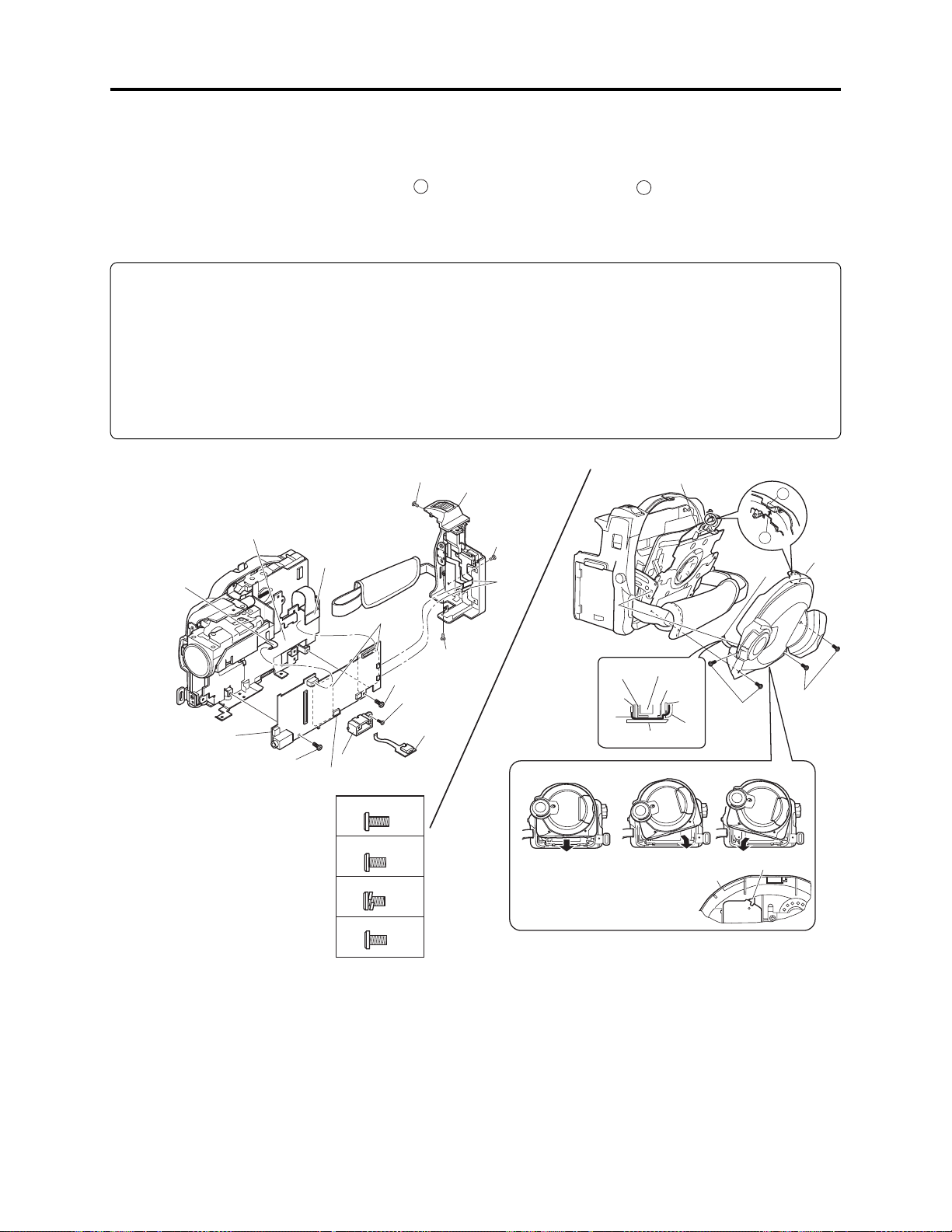
Troubleshooting > Trouble Diagnosis
2) Attach the MAN-H/MAN circuit board independently to the frame, and connect the DRF-H/DRF
circuit board to it.
3) Assemble the USB holder, USB-H/USB circuit board and rear cover.
4) Assemble the disc cover so that hinge 1 of side case-R fits into point 2 at the top of inside of disc
cover. Do not incline the disc cover at this time: Inclining the cover when assembling it could
break the switch inside the cover.
Note:
Attach the MAN-H/MAN circuit board independently of the frame only when setting to service
position (A).
When setting to service position (B) or during normal assembly, be sure to connect the AEL-H/AEL
circuit board to MAN-H/MAN circuit board first, and then attach them to the frame.
If the AEL-H/AEL circuit board is connected to MAN-H/MAN circuit board that is already attached
to the frame, connection error may occur, or the circuit boards or frame could be damaged.
(b)
2)
(a)
2) [G]
(a) MAN-H/MAN circuit board
(b) Frame
(c) DRF-H/DRF circuit board
(d) USB holder
(e) USB circuit board
(f) Rear cover
(g) Disc cover
(h) Hinge of side case-R
(i) Flat cable
(j) Disc drive unit
(k) Loader
(m)Side case-R
(n) Heat sink rubber
3) [F]
2) (c)
(n)
2) [G]
3) [F]
3) (e)
3) (d)
4)
[A] M1.7x4 (Black)
[F] M1.6x2.5 (Black)
[G] M1.7x3 (Gold)
[M] M1.7x3 (Black)
(f)
3) [M]
3)
3) [A]
Correct Incorrect Incorrect
Installing and inclined disc
cover could damage the switch
in side the disc cover.
Fig. 4-7-3 Setting to service position (A)
(h)
2
1
4) (i)
(j)
(b)
(a)
(i)
(m)
(k)
(h)
(g)
Disc
cover
4) [F]
Switch
(g)
4) [F]
4 - 36

Troubleshooting > Trouble Diagnosis
(2) Setting to service position (B)
Service position (B) is mainly used for trouble
diagnosis of the video and audio signal
systems.
Perform trouble diagnosis using the check
points on MAN-H/MAN and AEL-H/AEL
circuit
Remove the MAN-H/MAN and AEL-H/AEL
circuit boards in advance, referring to “5
Disassembly and Reassembly”.
LEAD
WIRES
MAN-H/MAN
CIRCUIT
BOARD
1) Solder a lead wire of approx. 10 cm to the
check points (except for IC pins) on side A/B
of MAN-H/MAN circuit board and side B of
AEL-H/AEL circuit board, referring to “4-7-1
Trouble diagnosis table” and “C-1 MAN-H/
MAN” and “C-2 AEL-H/AEL” circuit board
diagrams. (See Figs. 4-7-5, 4-7-6)
MAN-H/MAN
Ciruit Board (Side A)
TL2090 TL2085 TL2086 TL2082
TL2089 TL2091 TL2084 TL2095
MAN-H/MAN
Ciruit Board (Side B)
TL6006
TL6009
TL6010
TL0522
TL1534
TL0504
TL1535
TL0515
TL0512
TL0520(GND)
TL0521(GND)
TL0511
TL0510
TL0513
TL0517
TL0518
TL1547
TL1543
LEAD
AEL-H/AEL
WIRES
CIRCUIT
BOARD
Fig. 4-7-4 Service Position (B)
TL7030
TL7028
TL6101
TL6102 TL7041
TL3715
Ciruit Board (Side B)
: Check point (TL: Test land)
: Lead wire
TL3701(GND)
AEL-H/AEL
Fig. 4-7-6 Lead wire soldering of AEL-H/AEL
circuit board
: Check point (TL: Test land)
: Lead wire
Fig. 4-7-5 Lead wire soldering of MAN-H/MAN
circuit board
4 - 37

Troubleshooting > Trouble Diagnosis
2) Assemble the MAN-H/MAN and AEL-H/AEL
circuit boards on the frame.
3) Assemble the SHE-H/SHE circuit board and
accessory shoe. (See Fig. 4-7-7)
4) Assemble the USB holder, USB-H/USB
circuit board, rear cover and EVF unit.(See
Fig. 4-7-8)
5) Assemble the disc cover so that hinge 1 of
side case-R fits into point 2 at the top of
inside of disc cover. Do not incline the disc
cover at this time: Inclining the cover when
assembling it could break the switch inside
the cover.
6) Assemble the front block.
(a) MAN-H/MAN circuit board
(b) AEL-H/AEL circuit board
(c) Frame
(d) SHE-H/SHE circuit board
(e) Accessory shoe
(f) Heat sink rubber
(g) USB holder
(h) USB circuit board
(i) Rear cover
(j) EVF unit
(k) Disc cover
(m)Hinge of side case-R
(n) Side case-R
(p) Flat cable
(q) Disc drive unit
(r) Loader
(j)
4)
4) [F]
(e)
(c)
3) [H]
2)
2)
(f)
(a)
2) [G]
(b)
[G] M1.7x3 (Gold)
[H] M1.6x2 (Gold)
2) [G]
2) [G]
Fig. 4-7-7 Setting to service position (B) -1/2-
(i)
4) [A]
4) [M]
4)
4) [A]
(m)
1
5) (p)
3) [G]
3) (d)
2
(k)
6) [B]
(u)
4) [F]
4) (h)
5)
4) (g)
Correct
Installing and inclined disc
cover could damage the switch
in side the disc cover.
6) B]
[A] M1.7×4 (Black)
6)
[B] M1.7×4 (Silver)
[F] M1.6×2.5
(Black)
[M] M1.7×3 (Black)
Fig. 4-7-8 Setting to service position (B) -2/2-
4 - 38
(p)
(c)
(a)
(q)
(n)
(r)
(m)
(k)
Incorrect
Disc
cover
5) [F]
Incorrect
5) [F]
Switch

Troubleshooting > Trouble Diagnosis
(3) Setting to service position (C)
Service position (C) is mainly used for trouble
diagnosis of the system of operation buttons on
side case-L.
Perform trouble diagnosis using the check
points on MAN-H/MAN and AEL-H/AEL
circuit boards.
Set to service position (B) in advance.
L-BLOCK
AEL-H/AEL
CIRCUIT
BOARD
LEAD
WIRES
1) Connect the L block to AEL-H/AEL circuit
board. (See Fig. 4-7-10)
(a) L block
(b) AEL-H/AEL circuit board
(a)
1)
Fig. 4-7-10 Setting to service position (C)
SAF-H/SAF
CIRCUIT
BOARD
Fig. 4-7-9 Service Position (C)
(b)
1)
1)
(c)
LEAD
WIRES
4 - 39

Troubleshooting > Trouble Diagnosis
(4) Setting to service position (D)
Service position (D) is used for trouble
diagnosis of the LCD monitor.
Remove the LCD case-U, MR circuit board and
fulcrum block in advance, referring to “5.
Disassembly and Reassembly”.
1) Connect the flat cable of fulcrum block to
LCD and AEL-H/AEL circuit boards.
2) Connect the MR circuit board to LCD circuit
board.
(a) Fulcrum block
(b) LCD circuit board
(c) AEL-H/AEL circuit board
(d) MR circuit board
(e) MAN-H/MAN circuit board
MR
CIRCUIT
AEL-H/AEL
CIRCUIT
BOARD
FULCRUM
BLOCK
BOARD
Fig. 4-7-11 Service Position (D)
(e)
LCD
CIRCUIT
BOARD
1)
(c)
(a)
1)
(d)
Fig. 4-7-12 Setting to service position (D)
(b)
2)
4 - 40

4-8 Procedure for Removing Disc from Faulty the DVD Video
Camera/Recorder
4-8-1 Item to be checked
Connect the AC adapter/charger or charged battery pack (power supply), making sure the ACCESS
indicator turns off, and then press the DISC EJECT button again.
Note: Even with normal product, the disc cannot be removed while the ACCESS indicator is lit or
blinking.
Information:
Connect the AC adapter/charger or charged battery pack (power supply) before pressing the DISC
EJECT button.
The DISC EJECT button will work even if a power supply is not connected.
Prohibition
After the above check, be sure to disconnect the AC adapter/charger or battery from the DVD video
camera/recorder.
The DVD video camera/recorder has a built-in laser emitter block. Never look into it: If laser beam
strikes your eye, it could cause serious vision damage.
4-8-2 How to remove disc - DZ-MV550E, DZ-MV580E)
If the disc cannot be ejected after performing “4-8-1 Item to be checked”, remove it using the
procedure in this section.
Information:
Numbers in diagrams are step numbers of setting procedure, and letters in brackets [ ] show the
types of screw.
1) Turn the hood in the direction of the arrow
to remove it.
2) Remove the lens cover in the direction of the
arrow.
3) Remove the space sheet that covers the
opening for operating lock arm.
4) Use a fine-tipped flat-bladed screwdriver,
etc. to move the lock arm in the direction of
the arrow, and then open the disc cover.
5) Reset the DVD video camera/recorder in the
procedure of “4-2-2 System reset procedure”.
However, the various settings return to
default
1)
HOOD
LOCK ARM
LENS COVER
3) SPACE SHEET
2)
DISC
COVER
Information:
When reinstalling removed components, use
the reverse procedure to removal.
4)
Fig.4-8-1
4 - 41

4-8-2a How to remove disc - DZ-MV1000E(UK)
If the disc cannot be ejected after performing “4-8-1 Items to be checked”, remove it using the
procedure in this section.
Information:
Numbers in diagrams are step numbers of setting procedure, and letters in brackets [ ] show the
types of screw.
1) Turn the hood in the direction of the arrow
to remove it.
2) Remove three screws [A], and then remove
the filter piece, being careful not to scratch
the lens surface with screwdriver at this
time.
3) Remove the lens cover in the direction of the
arrow.
4) Use a fine-tipped flat-bladed screwdriver,
etc. to move the lock arm in the direction of
the arrow, and then open the disc cover.
[A] M1.7x4 (Black)
1)
Lock arm
Filter
piece
2) [A]
Hood
Lens
cover
Disc cover
3)
Information:
When reinstalling removed components, use
the reverse procedure to removal.
4)
Fig.3-1-1 How to remove disc
4 - 41a

Troubleshooting > Special Functions
4-9 Special Functions
Restriction:
The information included in this section is exclusively for service personnel: Do not disclose it to
persons other than service engineers.
4-9-1 Forced formatting of DVD-RAM disc
(1) Application/Symptom
Perform this procedure when the Disc Navigation screen does not start normally due to a defect in
data on disc and formatting is not possible by the procedure explained in instruction manual.
(2) Operational procedure
Caution:
1) Initialization will delete all data on disc: Copy the necessary files to PC, etc.
2) Do not turn power off or remove the disc during initialization: Such an interruption will make
the disc unusable.
1) Connect the AC adapter/charger, and set the power
switch to “VIDEO” or “PHOTO”.
Be sure to use the AC adapter/charger for formatting
disc: If power is interrupted during work, the disc could
become unusable.
2) Make sure that the DVD-RAM disc to be formatted is
free from dirt or scratch. If the disc is dirty, clean it; if
the disc is scratched, replace it. Any dirt or scratch on
disc could disable normal formatting. (Fig. 4-9-1)
3) Insert the DVD-RAM disc to be formatted.
4) After the disc is recognized, operate the following buttons
to display the disc formatting screen (Fig. 4-9-2):
Hold down the SELECT, REC and + (plus) buttons
simultaneously for at least 3 seconds
5) Use the joystick to choose “YES” and press the center of
joystick:
The initialization will start and message “Formatting ...”
will appear.
6) When formatting is complete, message “Finished” will
appear for several seconds, and then the normal screen
will automatically be restored.
Use soft cloth to clean
from inner to outer
circumference in
axial direction.
[Never use solvent.]
Fig. 4-9-1 Disc cleaning method
Format Disc
!
Disc is not formated.
Format the disc now?
YES
ENTER
NO
Fig. 4-9-2 Screen for Disc Formatting
4 - 42

Troubleshooting > Special Functions
4-9-2 EEPROM data backup and write
(1) Application
Perform this work whenever you replace the MAN-H/MAN circuit board on which the EEPROM is
mounted.
Create a backup file of the data in EEPROM to be replaced in a PC, and write the backup file to
new EEPROM: Some adjustment items that are performed after replacement can be omitted.
Refer to “6-3-2 List of Adjustments Needed After Replacing Major Components” for adjustment
items that can be omitted.
(2) Preparations
1) Connect the DVD video camera/recorder, jig/tool and power supply as shown in Fig. 4-9-3.
Refer to “6-1-1 List of Jigs and Tools used when Creating Reference Data” and “6-1-2 Power
Supply and Materials for Creating Reference Data” for details on jig/tool and power supply in the
figure.
2) Copy the adjustment program to HDD of PC.
Refer to “6-1-5 Copying or Deleting Adjustment Program” for copying.
3) Start the adjustment program in order to display the adjustment menu screen on PC display.
Prohibition:
Completely assemble the DVD video camera/recorder; create backup file of EEPROM data and
write it with only the adjustment cover removed (see Fig. 4-9-3).
Do not attempt to perform work with the DVD video camera/recorder disassembled: Doing so is
very dangerous because the DVD video camera/recorder incorporates high-voltage circuits and a
laser emitter block.
Note:
1) Always connect the Skylark connection jig before connecting the DC power cord to the DVD
video camera/recorder: Connecting the Skylark connection jig after powering the DVD video
camera/recorder could cause a fault.
2) Connect the Skylark connection jig so that the lead wires from jig face up.
4 - 43
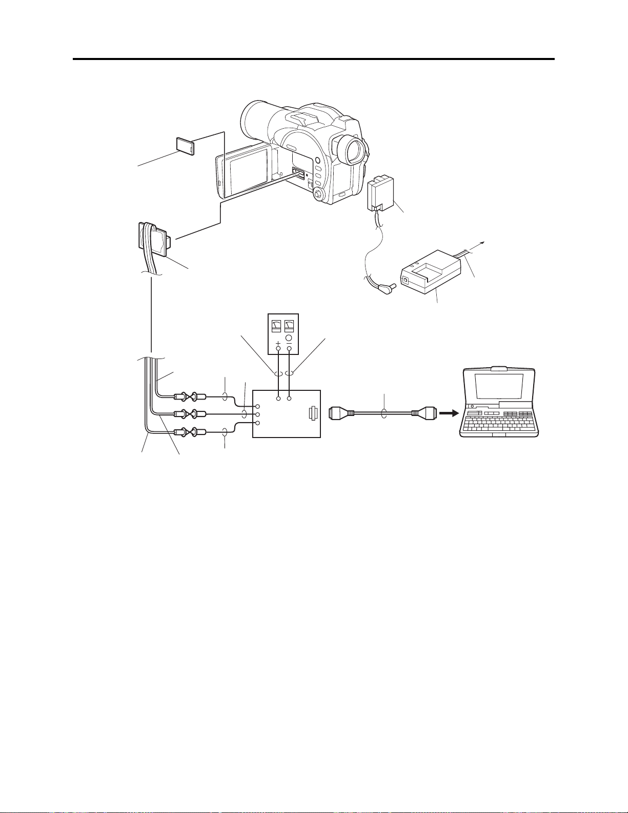
Troubleshooting > Special Functions
REMOVE THE
ADJUSTMENT COVER
[Refer to "(1) Adjustment cover"
in "5-3 Disassembly".]
DC POWER
CORD
To AC OUTLET
SD
(PIN 20)
SKYLARK
CONNECTION
JIG
(No. TP14161)
GND
(PIN 16)
RD
(PIN 18)
RED
BLK
WHT
YEL
DC
POWER
SUPPLY
(5V/1A)
DSP-R JIG
(No. 7099448)
DZ-ACS1
BLK
RS-232C
CABLE
Fig. 4-9-3 Connections when creating backup file of EEPROM data and writing
POWER CABLE
PC
4 - 44

FINISHED
FINISHED READING DATA
OK
7
Troubleshooting > Special Functions
(3) Backup method
Information:
If it is not possible to back up the data in EEPROM to be
replaced because the DVD video camera/recorder is not
turned on, etc., replace the MAN-H/MAN circuit board, and
then refer to “6-4-1 Initial Data Write”.
1) Choose DATA INITIALIZE on the ADJUST MENU
screen.
2) Click the EXECUTE button on ADJUST MENU screen
to proceed with the DATA INITIALIZE MENU screen.
3) Choose Original Data Backup on the DATA INITIALIZE
MENU screen.
Note:
Do not choose “Initial Data Write” on the DATA
INITIALIZE MENU.
Refer to “6-4-1 Initial Data Write” after backup for
“Initial Data Write”.
ADJUST MENU screen
MANUAL ADJUSTMENT PROGRAM for SERVICE STATION
MODEL NAME:
ADJUST MENU
CONNECTION
××××
DATA INITIALIZE
VIDEO LEVEL
BURST LEVEL
SAMPLING PULSE
AUTO FUCUS
AUTO IRIS CONTROL
MATRIX
CHROMA GAIN
SPOT NOISE
LCD
EVF
EXECUTE
2
1
DATA INITIALIZE MENU screen
Data Initialize
FILE MENU
Initial Data Write
RETURN
4) Click the EXECUTE button on DATA INITIALIZE
MENU screen to proceed with the BACKUP FILE
SELECT screen.
5) From the BACKUP FILE SELECT screen, select or set
the names of folder and file in which the data is stored.
This section refers to the folder and file as “EEP” and
“backup.eep” for explanation: Freely select and set easyto-understand names.
6) Click the SAVE button on BACKUP FILE SELECT
screen to start backup.
The progress status can be confirmed using the
PROGRESS STATUS dialog.
7) When backup is complete, the BACKUP FINISHED
dialog will appear: Click the OK button in dialog to
restore the DATA INITIALIZE MENU screen.
8) Then click the RETURN buttons on each menu screen to
restore the MODEL SELECT screen, and click the EXIT
button on MODEL SELECT screen to exit the
adjustment program.
9) Disconnect the DVD video camera/recorder, jig/tool and
power supply, and then replace the MAN-H/MAN circuit
board.
Backup Data Write
Original Data Backup
4
CONNECTION
3
EXECUTE
BACKUP FILE SELECT screen
Look in
(T):
File name (N):
File of type (T):
EEP
backup
.eep
*
5
PROGRESS STATUS dialog
EEPROM Data Backup
PLEASE WAIT A MOMENT
BACKUP FINISHED dialog
8
RETURN
Save
Cancel
?
6
(S)
4 - 45

Troubleshooting > Special Functions
FINISHED
FINISHED WRITING DATA
OK
7
(4) Write method
Restrictions:
Never write data of any other product.
The EEPROM data includes adjustment values, etc. that
are peculiar to that product: It is different for each
product even if the model is the same.
If you write the data of another product by mistake,
rewrite the correct data.
1) Choose DATA INITIALIZE on the ADJUST MENU
screen.
2) Click the EXECUTE button on ADJUST MENU screen
to proceed with the DATA INITIALIZE MENU screen.
3) Choose Backup Data Write on the DATA INITIALIZE
MENU screen.
4) Click the EXECUTE button on DATA INITIALIZE
MENU screen to proceed with the WRITE FILE
SELECT screen.
5) From WRITE FILE SELECT screen, select the folder
and file in which the data has previously been backed
up.
This section refers to the folder and file as “EEP” and
“backup.eep” for explanation.
6) Click the OPEN button on WRITE FILE SELECT screen
to start writing.
The progress status can be confirmed using the
PROGRESS STATUS dialog.
7) When writing is complete, the INITIALIZATION
FINISHED dialog will appear: Click the OK button in
dialog to restore the DATA INITIALIZE MENU screen.
8) Click the RETURN button on DATA INITIALIZE
MENU screen to restore the ADJUST MENU screen,
and then perform adjustment according to “6-3-2 List of
Adjustments Needed After Replacing Major
Components”.
ADJUST MENU screen
MANUAL ADJUSTMENT PROGRAM for SERVICE STATION
MODEL NAME:
ADJUST MENU
CONNECTION
××××
DATA INITIALIZE
VIDEO LEVEL
BURST LEVEL
SAMPLING PULSE
AUTO FUCUS
AUTO IRIS CONTROL
MATRIX
CHROMA GAIN
SPOT NOISE
LCD
EVF
EXECUTE
2
1
DATA INITIALIZE MENU screen
Data Initialize
FILE MENU
Initial Data Write
Backup Data Write
Original Data Backup
4
CONNECTION
3
EXECUTE
WRITE FILE SELECT screen
Look in
(T):
backup.eep
File name (N):
File of type (T):
EEP
5
backup.eep
.eep
*
RETURN
8
RETURN
?
6
Open
Cancel
PROGRESS STATUS dialog
DATA INITIALIZE
PLEASE WAIT A MOMENT
INITIALIZATION FINISHED dialog
4 - 46

5
Disassembly and Reassembly
5-1 Items to Be Checked
(1) Checking Disc
Connect the AC adapter/charger or charged battery, and then press the DISC EJECT button to
make sure that no disc is inserted. After check, close the disc insertion block.
If the disc insertion block does not open normally, refer to “4-8 Procedure for Removing Disc from
Faulty the DVD Video Camera/Recorder”.
Prohibition
After the above check, be sure to disconnect the AC adapter/charger or battery from the DVD video
camera/recorder.
The DVD video camera/recorder has a built-in laser emitter block. Never look into it: If Laser beam
strikes your eye, it could cause serious vision damage.
(2) Checking Card
Make sure that no card is loaded in the card slot. After check, close the card slot cover.
5-2 Order of Disassembly
Refer to “Disassembly Flowchart” in Fig. 5-2-1 for the order of removing components.
When reassembling components, use the reverse order to removal unless otherwise specified.
Note:
When replacing components, be sure to use only those shown in “Replacement Parts List”.
Information:
1) Board names suffixed with “-H” are for DZ-MV580E.
2) The procedures for disassembling and reassembling the DZ-MV580E and DZ-MV550E are the
same, except for the following components:
a) SHE-H circuit board
b) SHE circuit board
c) Accessory shoe
d) Lens unit (SEN-H circuit board, CCD image sensor, crystal filter, cushion)
3) The lens unit in DZ-MV550E includes components equivalent to cushion, crystal filter, CCD
image sensor and SEN-H circuit board, which are discrete from the lens unit in DZ-MV580E.
5 - 1

Disassembly and Reassembly > Order of Disassembly
Reading Disassembly Flowchart:
After locating the target component in the flowchart, remove all components of the target in
sequence, following the arrows (routes) from the top of flowchart. If multiple routes exist to the
target component from the top of flowchart, remove all the components on all the routes.
Parts Name
Adjustment cover
Food
Lens cover
SAF-H/SAF
circuit board
L-Block
Front block
R-Block
DZ-MV580E
SHE-H circuit board
Accessory shoe
DZ-MV550E
SHE circuit board
Item No.
5-3
(1)
5-3
(2)
5-3
(3)
5-3
(4)
5-3
(4)
5-3
(12)
5-3
(13)
SWL3-H/SWL3
circuit board
Side case-L
LCD Unit
SWL2 circuit board
Jack cover
FRT-H/FRT
circuit board
Microphone
Microphone cover
Disc cover
AEL-H/AEL
circuit board
MAN-H/MAN
circuit board
5-3
(7)
5-3
(8)
5-3
(5)
5-3
(6)
5-3
(10)
5-3
(15)
Side case-L
LCD case-U
MR circuit board
Fulcrum block
Front case
USB holder
USB-H/USB
circuit board
Rear cover
EVF unit
Camera block
5-3
(9)
5-3
(11)
5-3
(16)
Fulcrum cover-U
Fulcrum cover-B
Fulcrum unit
LCD case-B
LCD circuit board
Hand strap
DZ-MV580E
GYR-H circuit board
Lens frame
Lens unit
Cushion
Crystal filter
CCD image sensor
SEN-H circuit board
5-3
(20)
5-3
(21)
5-3
(11)
5-3
(22)
DZ-MV550E
Accessory shoe
Link bracket
5-3
(14)
5-3
(17)
Drive block
Side case-L
5-3
(18)
Fig. 5-2-1
5 - 2
Loader
DRF-H/DRF
circuit board
DVD Disc drive unit
Lock unit
Frame
5-3
(19)
DZ-MV550E
GYR circuit board
Lens frame
Lens unit
5-3
(23)

Disassembly and Reassembly > Disassembly
5-3 Disassembly
Information:
Numbers in disassembly procedure diagrams are step numbers for disassembling order, and letters
in brackets [ ] show the types of screw. Letters in brackets ( ) show the name of parts.
(1) Adjustment Cover
1) Open the LCD monitor (b).
2) Insert a fine-tipped flat-bladed screwdriver
(a) Adjustment cover
(b) LCD monitor
(c) Side case-L
(d) Flat-bladed screwdriver
(d) into the groove of adjustment cover (a),
and remove the adjustment cover in the
direction of the arrow, being very careful not
to scratch the adjustment cover or side
case-L (c) with screwdriver.
(2) Hood and Lens Cover (DZ-MV550E, DZ-MV580E)
1) Turn the hood (a) in the direction of the
arrow to remove it.
2) Remove the lens cover (b) in the direction of
the arrow.
(a) Hood
(b) Lens cover
(b)
1)
(d)
1)
(c)
(a)
2)
Fig. 5-3-1
(b)
5 - 3
2)
(a)
Fig. 5-3-2
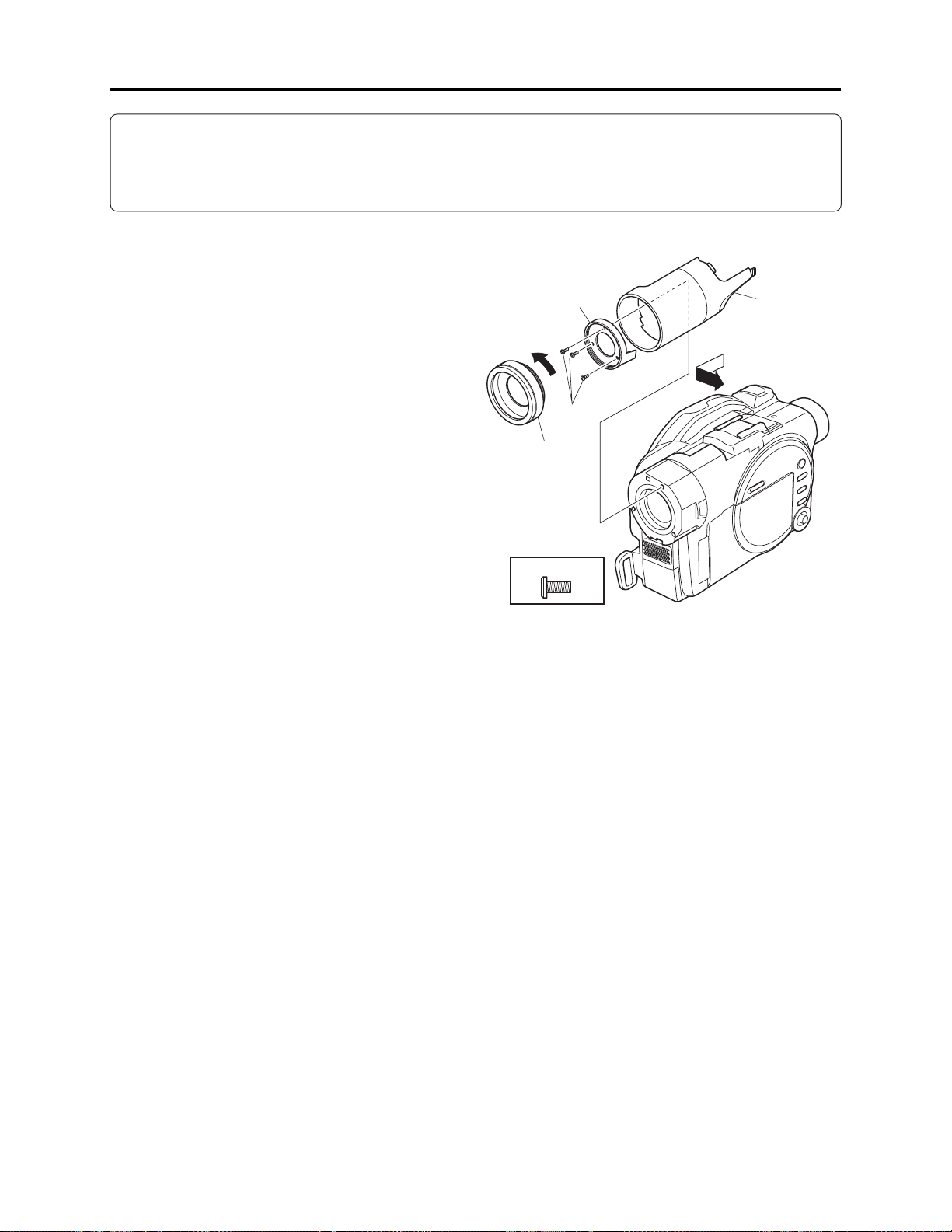
Disassembly and Reassembly > Disassembly
Information:
Since user cannot replace the DZ-MV1000E(UK) lens cover, the lens cover cannot be removed
unless the filter piece
*1: On DZ-MV550E it is not necessary to remove the filter piece when removing the lens cover.
(*1)
is also removed.
(2a) Hood, Filter Piece and Lens Cover (DZ-MV1000E)
1) Turn the hood (a) in the direction of the
arrow to remove it.
2) Remove three screws [A], and then remove
the filter piece (b), being careful not to
scratch the lens surface with screwdriver at
this time.
3) Remove the lens cover (c) in the direction of
the arrow.
1)
[A] M1.7x4 (Black)
Fig. 5-3-2a Hood, Filter Piece and Lens Cover
Hood
Filter
Piece
2) [A]
Lens
cover
3)
5 - 3a

Disassembly and Reassembly > Disassembly
(3) SAF-H/SAF Circuit Board and L Block
1) Open the LCD monitor (c).
2) Remove three screws [A], two screws [N] and three screws [C].
3) Close the LCD monitor and open the L block (b) from the rear in the direction of the arrow:
Be careful not to damage the SAF-H/SAF circuit board (a) or flat cable between L block and R
block (d).
4) Remove the SAF-H/SAF circuit board. The SAF-H/SAF circuit board is a film-like board:
Do not bend or fold it.
5) Disconnect the flat cable between L and R blocks. Disconnect the flat cable between L and R
blocks: Do not forcibly pull out the flat cable from connectors at this time.
6) Remove the L block from R block (d) in the direction of the arrow.
(1)
(1) Unlock
(a) SAF-H/SAF circuit board
(b) L block
(c) LCD monitor
(d) R block
(2)
2) [C]
(2) Pull
(d)
(c)
1)
(b)
2) [C]
5)
2) [N]
2) [A]
3)
Fig. 5-3-3 Right side
2) [N]
4)
6)
2) [A]
(a)
Pattern no,
printed side
[A] M1.7x4 (Black)
2) [A]
[N] M1.7x4 (Silver)
[C] M1.7x4 (Silver)
Fig. 5-3-4 Bottom Side
5 - 4
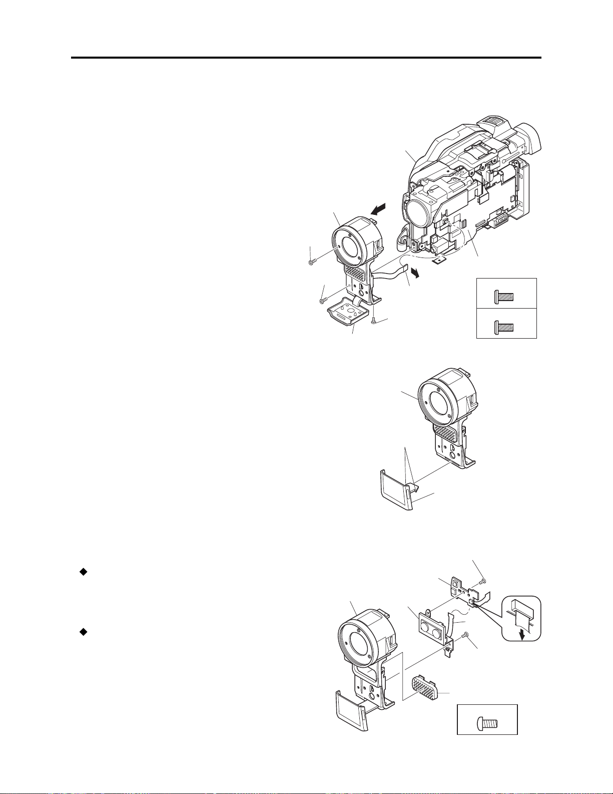
1) Tabs
(b)
(a)
Disassembly and Reassembly > Disassembly
(4) Front Block and R Block
1) Open the jack cover (c), and then remove one
screw [N].
2) Remove one screw [A] and one screw [N].
3) Remove the FRT-H/FRT circuit board (d)
from AEL-H/AEL circuit board (e) in the
direction of the arrow.
4) Remove the front block (a) from R block (b)
in the direction of the arrow.
(a) Front block
(b) R block
(c) Jack cover
(d) FRT-H/FRT circuit board
(e) AEL-H/AEL circuit board
(b)
4)
(a)
2) [A]
1) [N]
2) [N]
(c)
3)
(d)
Fig. 5-3-5
(e)
[A] M1.7×4 (Black)
[N] M1.7×4 (Silver)
(5) Jack Cover
1) Release the two tabs, and then remove the
jack cover (a).
(6) FRT-H/FRT Circuit Board, Microphone,
and Microphone Cover
FRT-H/FRT circuit board (a)
1) Disconnect the flat cable from microphone.
2) Remove one screw [D], and then remove the
FRT-H/FRT circuit board.
Microphone (b) and Microphone Cover (c)
3) Remove one screw [D], and then remove the
microphone and microphone cover from the
front case (d).
(a) Jack cover
(b) Front block
Fig. 5-3-6
(a) FRT-H/FRT circuit board
(b) Microphone
(c) Microphone cover
(d) Front Case
(d)
(b)
2) [D]
(a)
1)
3) [D]
(c)
[D] M1.7×4 (Black)
Fig. 5-3-7
5 - 5

Disassembly and Reassembly > Disassembly
(7) SWL3-H/SWL3 Circuit Board
1) Unplug the connector. Be sure to hold the connector using tweezers, etc. when unplugging it.
Pulling the cable when unplugging the connector could cause wire disconnection.
2) Remove one screw [D].
Procedure and caution for reassembly
1) Insert the switch knob (b) on SWL3-H/SWL3 circuit board between the knobs (c) of L cover.
2) Pass the cable to be connected to the SWL3-H/SWL3 circuit board through cable holder (e) under
ground plate (d) and wire retaining slit (f) as shown in the figure, so that the cable is laid out
along the side case L and L cover as far as possible.
(a) SWL3-H/SWL3 circuit board
(b) Switch knob
(c) Knobs of L cover
(d) Ground plate
(e) Cable Holder
(f) Wire retaining slit
[D] M1.7x4 (Black)
(b)
(c)
(a)
2) [D]
(e)
1)
(a)
(f)
(d)
Fig. 5-3-8
5 - 6

Disassembly and Reassembly > Disassembly
(8) Side Case-L, LCD Unit, and SWL2 Circuit Board
1) Unplug the connector. Be sure to hold the connector using tweezers, etc. when unplugging it.
Pulling the cable when unplugging the connector could cause wire disconnection.
2) Remove five screws [D].
3) Remove two screws [E], and then remove the LCD unit (b) and ground plate (d) from side case-L
(a).
4) Disconnect the one flat cable.
5) Remove two screws [D], and then remove the SWL2 circuit board (c).
Procedure and caution for reassembly
Pass the cable to be connected to the SWL3-H/SWL3 circuit board through the cable holder under
ground plate and the wire retaining slit as shown in Fig.5-3-8, making sure that the cable is laid out
along the side case L and L cover as far as possible.
Note:
Take great care when handling the LCD unit The LCD unit has an LCD panel that is a precision
component. Subjecting it to impact could result in a fault.
[D] M1.7x4 (Black)
[E] M2x5 (Silver)
2) [D]
(a) Side case-L
(b) LCD unit
(c) SWL2 circuit board
(d) Ground plate
(e) L cover
(f) SWL3-H/SWL3 circuit board
(a)
2) [D]
(d)
(b)
1)
4)
3) [E]
Fig. 5-3-9
(2)
(1)
(1) Unlock
(2) Pull
(1)
(c)
5) [D]
(f)
(e)
5 - 7

Disassembly and Reassembly > Disassembly
(9) LCD Case-U, MR Circuit Board, and Fulcrum Block
LCD Case-U (a)
1) Insert an awl (e), etc. into the screw hole, and turn the screw-hole bracket of fulcrum block 90° in
the direction of the arrow.
At this time, make no mistake with the turning direction: Turning in the wrong direction will
deform fulcrum cover-U.
2) Turn the fulcrum block 90° in the direction of the arrow.
3) Remove three screws [B].
4) Release the six tabs, and then remove the LCD case-U in the direction of the arrow. The MR
sheet (f) will detach at this time: Take care not to lose it.
MR Circuit Board (b)
5) Disconnect the MR circuit board from the LCD circuit board (g).
6) Remove the MR circuit board in the direction of the arrow. The MR circuit board is a film-like
board: Do not bend or fold it.
Fulcrum Block (c)
7) Disconnect the one flat cable.
8) Remove the fulcrum block in the direction of the arrow.
(a) LCD case-U
(b) MR circuit board
(c) fulcrum block
(d) LCD circuit board
(e) Awl
(f) MR sheet
(e)
1)
90
(c)
2)
90
[B] M1.7x4 (Silver)
(c)
6)
(f)
7)
Fig. 5-3-10
(b)
(d)
8)
(2)
(1) Unlock
(2) Pull
5)
4) Tabs
(1)
4) Tabs
3) [B]
(2)
(1)
(1) Unlock
(2) Pull
(1)
4) Tabs
3) [B]
4)
(a)
5 - 8

Disassembly and Reassembly > Disassembly
(10) Disc Cover
1) Remove the space sheet (b) that covers the opening for operating lock arm.
2) Use a fine-tipped flat-bladed screwdriver to move the lock arm (d) in the direction of the arrow to
open the disc cover (a).
3) Disconnect the one flat cable.
4) Open the card slot cover (g).
5) Remove four screws [F].
6) Remove the disc cover in the direction of the arrow: Be careful not to damage the flat cable (h)
that extends from the disc cover.
Procedure and caution for reassembly
1) Reinstall the disc cover so that the hinge 1 of side case-R fits into portion 2 at the inside top of
disc cover, and that the cover is not inclined. Installing and inclined disc cover could damage the
switch (SW8062) inside the disc cover.
2) Pass the flat cable extending from the disc cover through the gap between the frame and side
case-R, and then connect it to the MAN-H/MAN circuit board (f).
(a) Disc cover
(b) Space sheet
(c) Opening for operating lock arm
(d) Lock arm
(e) AEL-H/AEL circuit board
(f) MAN-H/MAN circuit board
(g) Card slot cover
(i)
[F] M1.6x2.5 (Black)
(h) Flat cable
(i) Hinge of side case-R
(j) Frame
(k) Side case-R
(m)Loader
(n) Disc drive unit
2
1
6)
(h)
(a)
4) (g)
5) [F]
(a)
(c)
Correct
1) (b)
(f)
3)
(1)
(2)
Fig. 5-3-11 Left Side
Incorrect Incorrect
(d)
2)
(c)
(e)
(1)
(1) Unlock
(2)Pull
(h)
5) [F]
(k)
(n)
(m)
Disc
(i)
(a)
Installing and inclined disc
cover could damage the switch
(SW8062) in side the disc cover.
cover
SW8062
(j)
(f)
Fig. 5-3-12 Right Side
5 - 9

Disassembly and Reassembly > Disassembly
(11) USB Holder, USB-H/USB Circuit Board, Rear Cover, EVF Unit, and Hand Strap
Note:
Before replacing the EVF unit, always perform “(1) BL DET Check” in “6-4-11 EVF”.
USB Holder (a) and USB-H/USB Circuit Board (b)
1) Remove one screw [F].
2) Disconnect the USB-H/USB circuit board from MAN-H/MAN circuit board (h).
3) Remove the USB-H/USB circuit board from USB holder in the direction of the arrow.
Rear Cover (c) and EVF Unit (d)
4) Remove the hand strap from side case-R (g).
5) Remove one screw [F] and one screw [A].
6) Disconnect the three flat cables, and then remove the rear cover along with the EVF unit.
7) Remove one screw [A], and then remove the EVF unit.
Hand Strap (e)
8) Remove screw [A], screw [D] and screw [M], and then remove the hand strap.
(e)
4)
(a) USB holder
(b) USB-H/USB Circuit Board
(c) Rear cover
(d) EVF unit
(f) Hand strap plate
(g) Side case-R
(h) MAN-H/MAN circuit board
(g)
8) [D]
8) [A]
(f)
(d)
6)
(h)
Fig. 5-3-13
(a)
2) (b)
5) [F]
(c)
7) [A]
8) [M]
6)
5) [A]
[A] M1.7x4 (Black)
[D] M1.7x4 (Black)
[F] M1.6x2.5 (Black)
1) [F]
[M] M1.7x3 (Black)
3)
5 - 10

Disassembly and Reassembly > Disassembly
(12) SHE-H Circuit Board and Accessory
Shoe in DZ-MV580E
1) Disconnect the SHE-H circuit board (a) from
AEL-H circuit board (c).
2) Disconnect the GYR-H (d) circuit board from
SHE-H circuit board.
3) Remove one screw [G], one screw [H], and
then remove the SHE-H circuit board along
with the accessory shoe (b).
4) Disconnect the SHE-H circuit board from
accessory shoe.
(a) SHE-H circuit board
(b) Accessory shoe
(c) AEL-H circuit board
(d) GYR-H circuit board
(13) SHE Circuit Board in DZ-MV550E
1) Disconnect the SHE circuit board (a) from
AEL circuit board (b).
2) Disconnect the GYR circuit board (c) from
SHE circuit board.
3) Remove one screw [G], and then remove the
SHE circuit board.
[G] M1.7x3 (Gold)
[H] M1.6x2 (Gold)
2) (d)
2) (c)
(b)
(c)
Fig. 5-3-14
3) [H]
4)
3) [G]
1) (a)
[G] M1.7x3 (Gold)
3) [G]
(a) SHE circuit board
(b) AEL circuit board
(c) GYR circuit board
(14) Accessory Shoe in DZ-MV550E
1) Remove one screw [H], and then remove the
accessory shoe (a).
(a) Accessory shoe
(b)
1) (a)
Fig. 5-3-15
[H] M1.6x2 (Gold)
(a)
1) [H]
Fig. 5-3-16
5 - 11

Disassembly and Reassembly > Disassembly
(15) AEL-H/AEL and MAN-H/MAN Circuit Boards
Note:
Before replacing the MAN-H/MAN circuit board, always perform “4-9-2 EEPROM data backup
and write”.
1) Disconnect the two flat cables.
2) Disconnect the DRF-H/DRF circuit board (c) from MAN-H/MAN circuit board (b).
3) Remove three screws [G].
4) Remove the AEL-H/AEL circuit board (a) that is assembled with MAN-H/MAN circuit board in
the direction of the arrow: It may be difficult to remove these circuit boards, since the heat sink
rubbers (e) on MAN-H/MAN circuit board may stick to the frame (d).
5) Remove the AEL-H/AEL circuit board from MAN-H/MAN circuit board in the direction of the
arrow.
Note:
Do not scratch the surface of IC2009 or IC2010: The surfaces of IC2009 or IC2010 are silicon
substrate (silicon wafer) that is semi-conducting. Scratching them could cause fault in operation.
Procedure and caution for reassembly
1) Be sure to paste the two heat sink rubbers (e) on the MAN-H/MAN circuit board: Neglecting to
paste the heat sink rubber could cause a fault.
2) Connect the MAN-H/MAN circuit board and AEL-H/AEL circuit board, and then attach them to
the frame. If the MAN-H/MAN and AEL-H/AEL circuit boards are attached to the frame
independently, a connection fault could result.
(a) AEL-H/AEL circuit board
(d)
2) (c)
1)
IC2010
e
3) [G]
(a)
(b) MAN-H/MAN circuit board
(c) DRF-H/DRF circuit board
(d) Frame
(e) Heat sink rubbers
e
IC2006
IC2009
(1) Unlock
(2) Pull
IC4002
IC4106
IC2010
DZ-MV580E
(2)
(b)
(b)
[G] M1.7x3 (Gold)
3) [G]
4)
Fig. 5-3-17
5 - 12
(1)
5)
3) [G]
DZ-MV550E

Disassembly and Reassembly > Disassembly
(16) Camera Block
1) Remove two screws [F], and then remove the camera block (a).
Procedure and caution for reassembly
Fit the hook (c) of camera frame onto the square hole (d) in frame before tightening the screws.
Note:
Take great care when handling the camera block: The camera block contains the lens unit, which is
a precision component. Subjecting the lens unit to any impact could result in a fault.
(a) Camera block
(b) Frame
(c) hook of camera frame
(d) square hole in frame
(d)
(c)
(b)
1) [F]
(17) Link Bracket
1) Remove two screws [H], and then remove
the link bracket (a).
1) [F]
1) [F]
Fig. 5-3-18
(a) Link bracket
(a)
1) [F]
DZ-MV550E
DZ-MV580E
(a)
[F] M1.6x2.5 (Black)
[H] M1.6x2 (Gold)
5 - 13
(a)
1) [H]
Fig. 5-3-19

Disassembly and Reassembly > Disassembly
(18) Drive Block and Side Case-R
1) Remove five screws [F] and two screws [A], and then remove the drive block (a) from the side
case-R (b).
Note:
Take great care when handling the drive block: The drive block contains the disc drive unit, which
is a precision component. Do not subject the disc drive unit to any impact: Doing so could cause a
fault.
(a) Drive block
(b) Side case-R
1) [F]
(b)
1) [F]
[A] M1.7x4 (Black)
[F] M1.6x2.5 (Black)
1) [F]
1) [F]
1) [A]
(a)
Fig. 5-3-20 Left side
1) [F]
1) [A]
Fig. 5-3-21 Bottom side
5 - 14

Disassembly and Reassembly > Disassembly
(19) Loader, DRF-H/DRF Circuit Board, Disc Drive Unit, Lock Unit, and Frame
Loader (a)
1) Remove two screws [L], and then remove the loader.
DRF-H/DRF Circuit Board (b) and Disc Drive Unit (c)
2) Remove three screws [K].
3) Disconnect the one flat cable.
4) Disconnect the DRF-H/DRF circuit board from DRV-R circuit board in disc drive unit.
Lock Unit (d) and Frame (e)
5) Remove one screw [H], and then remove the lock unit.
Note:
The disc drive unit is a precision component: Take great care when handling it. Do not subject the
disc drive unit to any impact: Doing so could cause a fault.
Procedure and caution for reassembly
Be sure to paste the heat sink rubber (f) on the frame: Neglecting to paste it could cause a fault.
(a) Loader
(b) DRF-H/DRF circuit board
(c) Disc drive unit
(d) Lock unit
(e) Frame
(f) Heat sink rubber
1) [J]
2) [K]
[H] M1.6x2 (Gold)
[J] M1.7x3 (Black)
[K] M1.7x1.8 (Gold)
(a)
2) [K]
(c)
5) [H]
(2)
(1)
(1) Unlock
(2) Pull
(1)
4) (b)
3)
(d)
(f)
Fig. 5-3-22
5 - 15
(e)
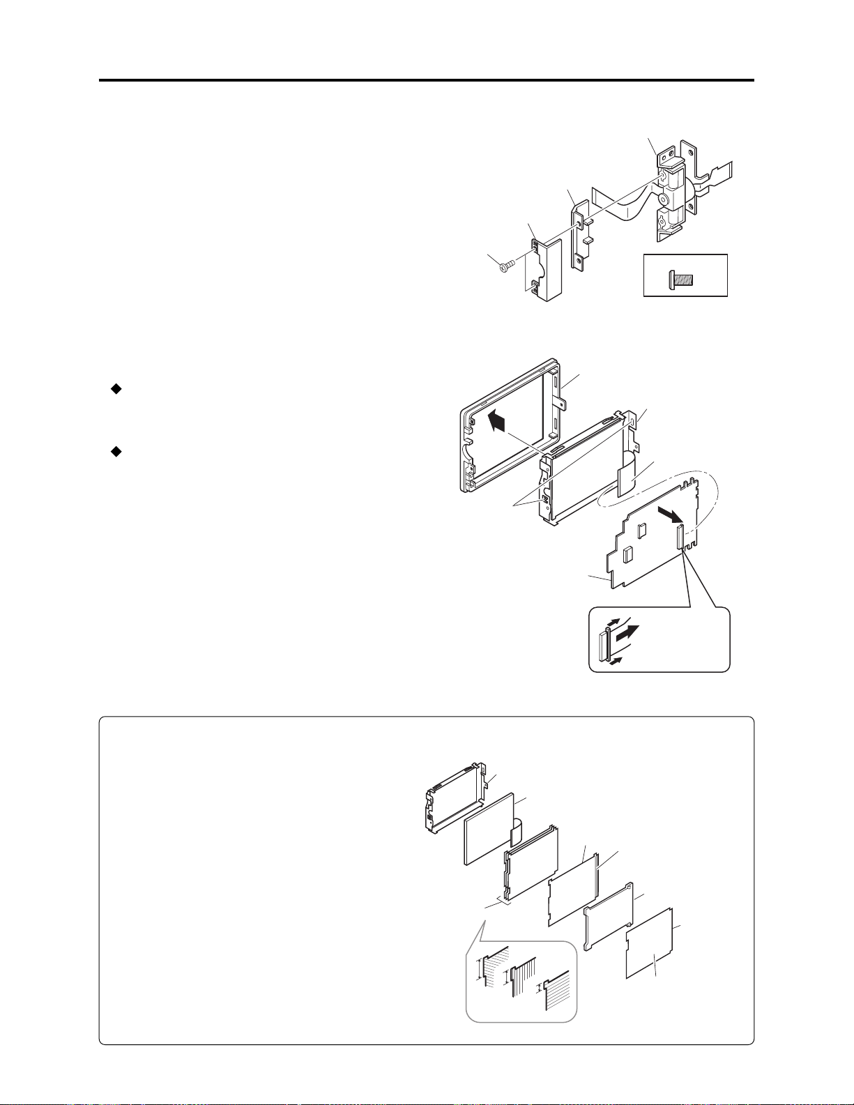
Disassembly and Reassembly > Disassembly
(20) Fulcrum Cover-U, Fulcrum Cover-B
and Fulcrum Unit
1) Remove two screws [P], and then remove the
fulcrum cover-U (a) and fulcrum cover-B (b)
from the fulcrum unit (c).
(21) LCD Case-B and LCD Circuit Board
LCD Case-B (a)
1) Remove the LCD case-B in the direction of
the arrow.
LCD Circuit Board (b)
2) Disconnect the one flat cable.
3) Release the two tabs, and then remove the
LCD circuit board.
Be careful not to deform LCD frame (c) at
this time.
(a) Fulcrum cover-U
(b) Fulcrum cover-B
(c) Fulcrum unit
(a)
1) [P]
1)
3) Tabs
(c)
(b)
[P] M1.6x3 (Black)
Fig. 5-3-23
(a)
(c)
2)
(b)
Note:
1) Do not remove the mirror sheet (d), light
guide plate (e), diffusion sheet (f), prism
sheets (g) or LCD panel (h) from the LCD
frame (c).
2) If the mirror sheet, light guide plate,
diffusion sheet, prism sheets or LCD panel
becomes detached from the LCD frame,
assemble them as shown in Fig. 5-3-25.
(a) LCD case-B
(1)
(b) LCD circuit board
(c) LCD frame
(2)
(1) Unlock
(2) Pull
(1)
Fig. 5-3-24 LCD Case-B and LCD Circuit Board
(c) LCD frame
(d) Mirror sheet
(c)
(g)
A
B
A > B > C
(h)
(f)
C
(e) Light guide plate
(f) Diffusion sheet
(g) Prism sheets
(h) LCD panel
Silver
surface
(e)
(d)
White
surface
5 - 16
Fig. 5-3-25 Assembling parts inside LCD frame

Disassembly and Reassembly > Disassembly
(22) GYR-H Circuit Board, Lens Frame, Lens Unit, Cushion, Crystal Filter, CCD Image
Sensor, and SEN-H Circuit Board in DZ-MV580E
GYR-H Circuit Board (a)
1) Remove two screws [D], and then remove the GYR-H circuit board.
Lens Frame (b)
2) Remove one screw [D].
3) Release the two tabs.
4) Remove the lens frame in the direction of the arrow.
Lens Unit (c), Cushion (d) and Crystal Filter (e)
5) Remove two screws [L], and then remove the lens unit, cushion and crystal filter.
CCD Image Sensor (f) and SEN-H Circuit Board (g)
6) Unsolder the fourteen points of CCD image sensor terminals on SEN-H circuit board.
Note:
1) The lens unit, crystal filter and CCD image sensor are precision components: Take great care
when handling them. Adherence of dust, foreign object, fingerprint, etc. to them, scratches or
impact, could cause a fault.
2) Never use metal tweezers to handle the crystal filter: Doing so could cause a fault.
Procedure and caution for reassembly
1) Take care with the orientation of crystal filter when assembling it: Incorrect orientation of the
crystal filter could cause a fault.
2) When assembling the lens unit into lens frame, insert the flat cable (h) of lens unit inside the lens
frame.
Color
(g)
6)
a
Transparent
a > b
(c)
(h)
(a) GYR-H circuit board
(b) Lens frame
(c) Lens unit
(d) Cushion
(e) Crystal filter
(f) CCD image sensor
(g) SEN-H circuit board
(h) Flat cable
(b)
(h)
2) [D]
4)
(f)
(c)
5) [L]
(d)
(e)
b
1) [D]
[D] M1.7x4 (Black)
(a)
[L] M1.7x5 (Silver)
(b)
3) Tabs
Fig. 5-3-26
5 - 17

Disassembly and Reassembly > Disassembly
(23) GYR Circuit Board, Lens Frame, and
Lens Unit in DZ-MV550E
Information:
The DZ-MV550E lens unit is set as a service
component: It includes the parts equivalent to
cushion rubber, crystal filter, CCD image
sensor and SEN-H circuit board of DZMV580E.
GYR Circuit Board (a)
1) Remove two screws [D], and then remove the
GYR circuit board.
Lens Frame (b) and Lens Unit (c)
2) Remove two screws [D], and then remove the
lens frame.
(a) GYR circuit board
(b) Lens frame
(c) Lens unit
1) [D]
(b)
(a)
2) [D]
[D] M1.7x4 (Black)
(c)
Caution:
1) The lens unit is a precision component: Take
great care when handling it. Do not allow
any dust to adhere to it, and do not subject it
to damage or impact: Doing so could cause a
fault.
2) Do not disassemble the lens unit: Doing so
could cause a fault.
Fig. 5-3-27
5 - 18

6
Adjustment
6-1 Creating Reference Data
The reference data is necessary for adjustment: The adjustment program will not operate normally
without it. Before adjustment, be sure to create the reference data, using the same model (with
normal camera block) as the one to be adjusted.
See section 6-1-1 and subsequent sections for details.
Information:
1) The reference data is used to reduce the difference between environments of servicing site and
factory (color temperature of light box, etc.). Using the reference data will increase adjustment
accuracy.
2) The reference data is usually created once for each model because it is recorded on hard disk
drive (HDD) of PC with the adjustment program. However, creating reference data again is
necessary in the following cases:
a) When performing adjustment using a light box that is different from that used when the
reference data was created.
b) When performing maintenance of the light box used when creating the reference data
(replacing fluorescent light, etc.).
c) When performing adjustment using a C12 light balancing filter that is different from that used
when the reference data was created.
d) When deleting the folder containing the adjustment program from HDD.
Restrictions:
If the same model with normal camera block as the one to be adjusted is not available, the reference
data can be created by the following procedure. However, reference data created this way has been
prepared at the factory, assuming the environment of service workplace, and may not be suitable
for all service workplaces. Therefore, it is recommended that you create reference data using the
same model with normal camera block as that to be adjusted.
1) Store the adjustment program on HDD, referring to “6-1-5 Copying or Deleting Adjustment
Program”.
2) Start up Explorer and open the refdata folder in map04w folder.
3) Refer to the following table to check the reference data file name of the model to be adjusted.
4) Copy the file with the same name as the reference data file name checked in step 3) in refdata
folder to map04w folder.
Model
DZ-MV580E
DZ-MV550E
Name of reference data file
m580ae.dat
m550e.dat
6 - 1

Adjustment > Creating Reference Data
6-1-1 List of Jigs and Tools used when Creating Reference Data
NEW
Adjustment floppy disk
Skylark connection jig
Parts No. TP14161
Note:Create the data using the adjustment data
downloaded from Intranet. If downloading
is not possible, obtain the floppy disk with
Parts No. TP13875
Personal computer (PC)
All of the following OS must operate normally on it.
(*1)
OS: Windows 95/98/98 Second Edition/Me/2000 Professional/XP/NT4.0
C12 light balancing filter
(Diameter: 46mm)
DSP-R jig
Parts No. 7099448
Parts No. 7099369
Step-up rings (Diameter 37 - 46 mm)
[Generally available]
Note: The filter diameter of DVD video camera/recorder is 37 mm: When
using a filter with a diameter of 46 mm, use a step-up rings for better
workability.
RS-232C cable (9-pin or 25-pin straight type)
[Generally available]
DZ-ACS1
AC adapter/charger
[Accessory]
(*2)
DC power cord
[Accessory: Parts No. EV11012]
AV/S input/output or output cable
[Accessory: Parts No. EW12521]
Power cable for AC adapter/
charger [Accessory]
(*2)
Example
*1: The adjustment program used on DVD video
camera/recorder is exclusively for Windows
95/98/98 Second Edition/Me/2000
Professional/XP/NT4.0: The program cannot
be run on MS-DOS.
*2: The part numbers of AC adapter/charger and
power cable are different depending on the
destination: Refer to the “Replacement Parts
List” for the part numbers.
6 - 2

Adjustment > Creating Reference Data
6-1-2 Power Supply and Materials for Creating Reference Data
1) DVD video camera/recorder that is the same model as the one to be adjusted and whose camera
block is operating normally.
Note:
It is recommended that you use a brand-new unit of the same model when creating the reference
data. If such a unit is not available, use the same model of the DVD video camera/recorder that is
received from customer for repairing fault in disc drive that is other than in the camera block,
and one where there is no problem in recording of camera image and the zoom is operating
normally.
2) 3100 K light box (maintenance is necessary)
3) Color monitor (color TV with AV input jacks)
4) DC power supply for DSP-R jig (5 V/1 A)
6-1-3 Connections when Creating Reference Data
Connect the DVD video camera/recorder (for creating reference data), jigs and test equipment as
shown in Fig. 6-1-1.
Prohibition:
Assemble the DVD video camera/recorder completely, and create reference data with only the
adjustment cover removed (see Fig. 6-1-1).
Do not attempt to create reference data with the DVD video camera/recorder disassembled: Doing
so is very dangerous because the DVD video camera/recorder incorporates high-voltage circuits and
a laser emitter block.
(1) Setting of light box
1) Use a light box whose color temperature is controlled with no flickering: Using an inappropriate
light box will interference with work.
(2) Setting and disassembly of DVD video camera/recorder
1) Refer to “(1) Adjustment cover” in “5-3 Disassembly” for how to remove the adjustment cover.
2) Set the light box 30-50 cm away from DVD video camera/recorder, and eliminate any effects from
surrounding light, except where such designation is given.
3) Set the lens surface of DVD video camera/recorder in parallel with the surface of light box as far
as possible, and adjust the focus.
4) Use a small tripod to fix the DVD video camera/recorder, making certain it does not move during
creation of reference data.
6 - 3

Adjustment > Creating Reference Data
Note:
1) Always connect the Skylark connection jig before connecting the DC power cord to the DVD
video camera/recorder : Connecting the Skylark connection jig after powering the DVD video
camera/recorder could cause a fault.
2) Connect the Skylark connection jig so that the lead wires from jig face up.
30-50cm
REMOVE THE
ADJUSTMENT COVER
[Refer to "(1) Adjustment cover"
in "5-3 Disassembly".]
SKYLARK
CONNECTION
JIG
RED
LIGHT BOX
TRIPOD
DC
POWER
SUPPLY
(5V/1A)
BLK
FRONT
SECTION
DC Power
CORD
To
VIDEO IN
AV/S INPUT/OUTPUT
CABLE
To AC OUTLET
POWER CABLE
DZ-ACS1
COLOR
MONITOR
YEL
SD
(PIN 20)
GND
(PIN 16)
RD
(PIN 18)
BLK
WHT
YEL
RS-232C
CABLE
DSP-R JIG
Fig. 6-1-1 Connections when Creating Reference Data
6 - 4
PC

Adjustment > Creating Reference Data
6-1-4 Settings when Creating Reference Data
When the connections for creating reference data are complete, set the DVD video camera/recorder
and test equipment as follows:
1) Make sure that no disc or card is inserted: Neither is necessary when creating reference data.
2) Set the power switch to “VIDEO” and quick mode switch to “OFF”: After that operate the DVD
video camera/recorder while watching the LCD monitor screen.
3) Press the MENU button to display the menu screen.
4) Use the joystick to choose “Initial Setup”, and then press the center of joystick.
5) Use the joystick to choose “Reset”, and then press the center of joystick: The screen for verifying
reset will appear.
6) Use the joystick to choose “ENTER”, and then press the center of joystick: Reset will be executed.
7) When reset is complete, operate the joystick by the above procedure to set the items on menu
screens as follows:
a) Specify Demo Mode “Off” in Initial Setup menu. Failing to specify Demo Mode “Off” will
interfere with adjustment.
8) Press the MENU button to restore the normal display.
Information:
The following table shows the menu status after the above settings:
The settings for Date Setup are not shown in the table below, since they do not have any meaning
when creating reference data.
Item
Program AE
White Balance
EIS
Dig. Zoom
MIC Filter
16:9
Recording Functions Setup
VIDEO Mode
Quality
Input Source
PHOTO Input
Self Timer
OSD Output
Camera Functions Setup
(*1)
(*1)
Setting
Auto
Auto
On
×40
Off
Off
FINE
FINE
CAMERA
Field
Off
Off
Item
Setting
LCD Setup
Brightness
Color Level
Initial Setup
Beep
Power Save
Record LED
Language
Demo Mode
*1: Dispaly only on models that have the line
input function.
On
Off
On
English
Off
+
+
6 - 5

Adjustment > Creating Reference Data
6-1-5 Copying or Deleting Adjustment Program
Information:
The adjustment program also includes a program for creating reference data.
(1) Copy
1) Start the PC.
2) Start Explorer and create a new folder in HDD of PC. The name “map04w” is recommended for
the folder: If a folder with the same name exists, give the folder a similar name that is easily
understandable.
Note:
Be sure to manage the adjustment programs for Windows and MS-DOS in different folders:
Managing them in the same folder will interfere with adjustment.
3) Copy all the folders and files on adjustment floppy disk to the map04w folder.
(2) Deleting
If it is necessary to delete the adjustment program from hard disk drive (HDD) of PC, delete the
map04w folder that was created during storage.
6-1-6 Starting and Terminating Reference Data Creation Program
Make sure that the connections are correct, the power switch on DVD video camera/recorder is set
to “VIDEO”, and the DC power supply for DSP-R jig is turned on: The reference data creation
program will not start unless the connections for creating reference data are correct, and the DVD
video camera/recorder or DSP-R jig is powered.
For subsequent operation, operate the PC mouse while watching the PC monitor screen.
Information:
1) Display ×××× on subsequent PC screen shows the model name.
2) The numbers on PC screens show the operational procedure.
(1) Start
1) Start the PC. If the PC has already started, terminate all other applications.
2) Start Explorer, and double-click the “SETUPforMAP2004W.EXE” file in map04w folder to start
the program.
3) Once the program has started, the COMMUNICATION PORT SETTING screen will appear.
6 - 6

OK
COM PORT ERROR
ERROR
!
Adjustment > Creating Reference Data
4) Choose the communication port to which the RS-232C
cable is connected, and then choose the radio button of
corresponding port on COMMUNICATION PORT
SETTING screen.
5) Click the OK button on the COMMUNICATION PORT
SETTING screen, and then proceed with the MODEL
SELECT screen.
Note:
If the following dialogs appear, perform the
troubleshooting below:
POWER OR CONNECTION ERROR dialog
ERROR
MAY OCCURE ON CABLE OR JIG OR CAMCORDER.
!
POWER FAILURE OR CONNECTION ERROR!
OK
COM PORT ERROR dialog
COMMUNICATION PORT SETTING
screen
MANUAL ADJUSTMENT PROGRAM for SERVICE STATION
MANUAL ADJUSTMENT PROGRAM
for SERVICE STATION
COM PORT SETTING
PORT
4
5
PORT 1
PORT 2
PORT 3
OK
PORT 4
PORT 5
PORT 6
EXIT
Copyright (C) HITACHI, Ltd 2003
When the power or connection error dialog appears:
A connection is incorrect or power is not turned on.
Make sure that all connections are correct and that
power is supplied to the reference data creating
device or DSP-R interface jig.
Clicking the OK button will finish the program:
After solving the problem, restart the program.
When the communication port error dialog appears:
There was a mistake in selecting communication port.
Check the communication port.
Clicking the OK button will finish the program:
Select the communication port again after restart.
6 - 7
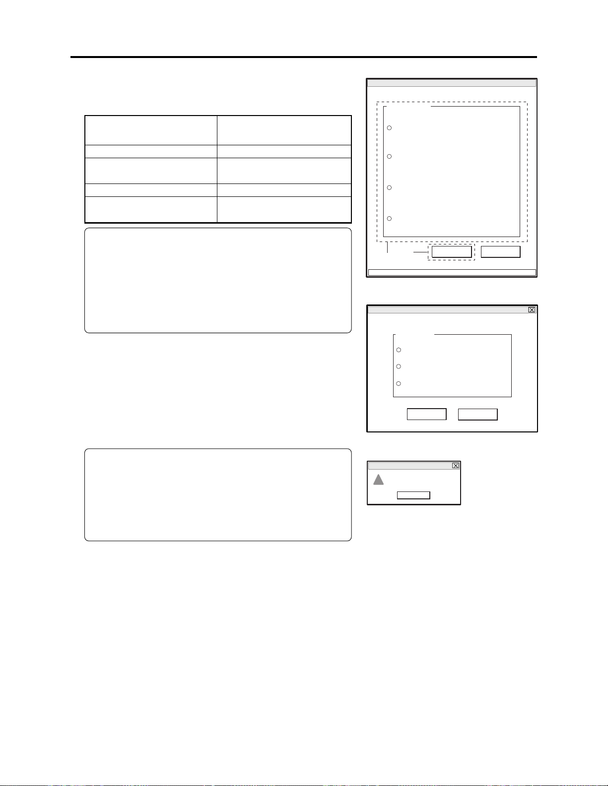
ERROR
!
File hundle error. [SYMBOL FILE]
OK
Adjustment > Creating Reference Data
6) Refer to the following table and choose the radio button
of corresponding model name in MODEL SELECT
screen.
Name of model
to be adjusted
DZ-MV580E/MV580E(UK)
DZ-MV580E(AU)/
MV580E(SW)/MV580E(SWH)
DZ-MV550E/MV550E(UK)
DZ-MV550E(AU)/
MV550E(SW)/MV550E(SWH)
Corresponding model name
on MODEL SELECT screen
DZ-MV580E
DZ-MV580ESW
DZ-MV550E
DZ-MV550ESW
Information:
The symbols in parentheses ( ) in the above model
names show the destinations and are displayed only
on packing box.
Refer to “2-5 Differences in Rating Labels and
Difference in Function” when checking the body of
DVD video camera/recorder to judge its destination.
7) Click the ENTER button in MODEL SELECT screen,
and then proceed with the SETUP MENU screen.
Refer to next item for subsequent operations.
If there is an error in model selection, the FILE
HANDLE ERROR dialog will appear. Click the OK
button, and then choose the correct model.
MODEL SELECT screen.
MANUAL ADJUSTMENT PROGRAM for SERVICE STATION
MODEL SELECT
× × × ×
× × × ×
× × × ×
× × × ×
6
CONNECTION
7
ENTER
SETUP MENU screen.
MANUAL ADJUSTMENT PROGRAM for SERVICE STATION
SETUP MENU
Matrix
White Balance
White Balance Abs
EXECUTE
RETURN
EXIT
Note:
If the FILE HANDLE ERROR dialog appears when the
correct model has been chosen, obtain (download) the
newest adjustment program, and then start over again.
If the FILE HANDLE ERROR dialog still appears with
the newest adjustment program, check with the factory.
FILE HANDLE ERROR dialog
6 - 8
 Loading...