

Hitachi DZ-MV580A, DZ-MV550A(K), DZ-MV580A(K), DZ-MV550A Service Manual

TK No. 0403E
DZ-MV580A
SERVICE MANUAL
DZ-MV580A(K)
DZ-MV550A
DZ-MV550A(K)
SPECIFICATIONS AND PARTS ARE SUBJECT TO CHANGE FOR IMPROVEMENT
DVD VIDEO CAMERA/RECORDER
2004March
MultiMediaCard
DO NOT RESELL OR DIVERT IMPROPERLY
Digital Media Division,Tokai
TM

Table of Contents
1 Safety Precaution for Repair ............. 1-1
1-1 Cautions ................................................... 1-1
1-2 Electrostatic Protection Measures ............ 1-2
1-3 Cautions When Handling DVD Drive ......... 1-2
1-4 Lead-Free Solder...................................... 1-3
1-5 Notes When Using Service Manual .......... 1-5
2 General Description ........................... 2-1
2-1 Overview .................................................. 2-1
2-1-1 Servicing method................................... 2-1
2-2 Features ................................................... 2-2
2-3 Specifications ........................................... 2-2
2-4 Major Differences from
Previous Models ....................................... 2-5
2-5 Compatibility of Recorded Discs ............... 2-7
2-6 Names of Parts......................................... 2-8
2-7 List of Abbreviations and Terms for
DVD Video Camera/Recorders ................. 2-10
3 Description of Operation ................... 3-1
3-1 Description of Structure ............................ 3-1
3-2 Description of Newly Adopted
Technology ............................................... 3-2
4 Troubleshooting.................................. 4-1
4-1 Procedure for Troubleshooting .................. 4-1
4-2 System Resetting/Resetting
Camera Functions .................................... 4-2
4-2-1 List of items to be reset ......................... 4-2
4-2-2 System reset procedure ........................ 4-4
4-2-3 Procedure for resetting
camera functions ................................... 4-4
4-3 Problem Guide.......................................... 4-5
4-4 Messages and Troubleshooting ................ 4-12
4-5 Self-Diagnosis Function and
Troubleshooting ........................................ 4-22
4-5-1 Message displayed by
self-diagnosis function ........................... 4-22
4-5-2 Error codes stored in flash memory....... 4-24
4-5-3 Major error codes and
troubleshooting ...................................... 4-25
4-6 Checking Versions of Firmware and
Updating ................................................... 4-27
4-6-1 Checking firmware versions................... 4-27
4-6-2 Updating firmware ................................. 4-28
4-7 Trouble Diagnosis ..................................... 4-30
4-7-1 Trouble diagnosis table .......................... 4-30
4-7-2 Disassembly/reassembly for enable
service position ..................................... 4-35
4-8 Procedure for Removing Disc from
Faulty DZ-MV580A/MV550A..................... 4-41
4-8-1 Item to be checked ................................ 4-41
4-8-2 How to remove disc ............................... 4-41
4-9 Special Functions ..................................... 4-42
4-9-1 Forced formatting of DVD-RAM disc ...... 4-42
4-9-2 EEPROM data backup and write ........... 4-43
5 Disassembly and Reassembly .......... 5-1
5-1 Items to Be Checked ................................ 5-1
5-2 Order of Disassembly ............................... 5-1
5-3 Disassembly ............................................. 5-3
(1) Adjustment Cover .................................. 5-3
(2) Hood, Filter Piece and Lens Cove ......... 5-3
(3) SAF-H/SAF Circuit Board and L Block... 5-4
(4) Front Block and R Block ........................ 5-5
(5) Jack Cover ............................................ 5-5
(6) FRT-H/FRT Circuit Board, Microphone,
and Microphone Cover .......................... 5-5
(7) SWL3-H/SWL3 Circuit Board................. 5-6
(8) Side Case-L, LCD unit, and
SWL2 Circuit Board ............................... 5-7
(9) LCD Case-U, MR Circuit Board,
and Fulcrum Block................................. 5-8
(10) Disc Cover ............................................. 5-9
(11) USB Holder, USB-H/USB Circuit Board,
Rear Cover, EVF Unit,
and Hand Strap ..................................... 5-10
(12) SHE-H/SHE Circuit Board and Accessory
Shoe in DZ-MV580A.............................. 5-11
(13) SHE Circuit Board in DZ-MV550A ......... 5-11
(14) Accessory Shoe in DZ-MV550A ............ 5-11
(15) AEL-H/AEL and MAN-H/MAM Circuit
Boards ................................................... 5-12
(16) Camera Block ........................................ 5-13
i

(17) Link Bracket........................................... 5-13
(18) Drive Block and Side Case-R ................ 5-14
(19) Loader, DRF-H/DRF Circuit Board,
Disc Drive Unit, Lock Unit, and Frame ... 5-15
(20) Fulcrum Cover-U, Fulcrum Cover-B,
and Fulcrum Unit ................................... 5-16
(21) LCD Case-B and LCD Circuit Board...... 5-16
(22) GYR-H Circuit Board, Lens Frame , Lens
Unit Cushion, Crystal Filter, CCD Image
Sensor, and SEN-H Circuit Board in
DZ-MV580A .......................................... 5-17
(23) GYR Circuit Board, Lens Frame, and
Lens Unit in DZ-MV550A ....................... 5-18
6 Adjustment .......................................... 6-1
6-1 Creating Reference Data .......................... 6-1
6-1-1 List of Jigs and Tools used when Creating
Reference Data ..................................... 6-2
6-1-2 Power Supply and Materials for Creating
Reference Data ..................................... 6-3
6-1-3 Connections when Creating
Reference Data ..................................... 6-3
6-1-4 Settings when Creating
Reference Data ..................................... 6-5
6-1-5 Copy or Deleting Adjustment Program... 6-6
6-1-6 Starting and Terminating Reference
Data Creation Program.......................... 6-6
6-1-7 Creating Reference Data ....................... 6-9
6-2 Setups for Adjustment .............................. 6-11
6-2-1 Checking Reference Data ...................... 6-11
6-2-2 List of Jigs and Tools for Adjustment ...... 6-11
6-2-3 Test Equipment, Power Supply and
Charts for Adjustment............................ 6-12
6-2-4 Connections for Adjustment................... 6-12
6-2-5 Settings for Adjustment.......................... 6-14
6-2-6 Starting and Terminating Adjustment
Program ................................................ 6-16
6-3 List of Adjustment Items ........................... 6-18
6-3-1 Adjustment Program
Hierarchy Diagram................................. 6-18
6-3-2 List of Adjustments Needed After
Replacing Major Components ............... 6-19
6-3-3 Purpose of Adjustments and
Incompleted Phenomenon ..................... 6-21
6-4 Adjustment Procedure .............................. 6-22
6-4-1 Initial Data Write .................................... 6-22
6-4-2 Video Level ............................................ 6-23
6-4-3 Burst Level ............................................ 6-24
6-4-4 Sampling Pulse ..................................... 6-25
6-4-5 Autofocus .............................................. 6-26
6-4-6 Auto Iris Control ..................................... 6-27
6-4-7 Matrix .................................................... 6-28
6-4-8 Chroma Gain ......................................... 6-29
6-4-9 Spot Noise.............................................. 6-31
6-4-11 LCD ...................................................... 6-32
6-4-12 EVF ...................................................... 6-39
7 Exploded View and Parts List............ 7-1
7-1 Exploded Views ........................................ 7-1
7-1-1 L Block and Front Block ......................... 7-1
7-1-2 R Block .................................................. 7-2
7-1-3 LCD Unit................................................ 7-3
7-1-4 DZ-MV580A Camera Block ................... 7-3
7-1-5 DZ-MV550A Camera Block ................... 7-3
7-2 Replacement Parts List ............................ 7-4
7-2-1 Mechanical parts list .............................. 7-4
7-2-2 Electrical parts list ................................. 7-5
S Schematic & Wiring Diagrams ........... S-1
S-1 DZ-MV580A Wiring Diagram ................. S-1
S-2 DZ-MV550A Wiring Diagram ................. S-2
S-3 GYR-H/GYR .......................................... S-3
S-4 FRT-H/FRT ............................................ S-3
S-5 DRF-H/DRF........................................... S-4
S-6 SWL3-H/SWL3 ...................................... S-4
S-7 SHE-H ................................................... S-5
S-8 SHE ....................................................... S-5
S-9 USB-H/USB ........................................... S-6
S-10 SAF-H/SAF ........................................... S-6
S-11 MR ........................................................ S-6
S-12 LCD ....................................................... S-7
S-13 SEN-H ................................................... S-8
S-14 BTB [AEL-H/AEL] .................................. S-9
S-15 LENS DRIVE [AEL-H/AEL] .................... S-10
S-16 AUD [AEL-H/AEL] .................................. S-11
S-17 EVF [AEL-H/AEL] .................................. S-12
S-18 SWL2 .................................................... S-13
S-19 IC BLOCK ............................................. S-14
ii

C Circuit Board Diagrams ..................... C-1
C-1 GYR-H................................................... C-1
C-2 GYR ...................................................... C-1
C-3 FRT-H .................................................... C-2
C-4 FRT ....................................................... C-2
C-5 DRF-H/DRF........................................... C-3
C-6 SHE ....................................................... C-3
C-7 SHE-H ................................................... C-4
C-8 SWL3-H/SWL3/SWL2 ........................... C-4
C-9 USB-H/USB ........................................... C-5
C-10 MR ........................................................ C-5
C-11 LCD ....................................................... C-6
C-12 SEN-H ................................................... C-7
C-13 SAF-H/SAF ........................................... C-7
C-14 AEL-H/AEL ............................................ C-8
C-15 MAN-H/MAN ......................................... C-9
C-16 DRV-R ................................................... C-10
C-17 HDM ...................................................... C-11
B Block Diagrams .................................. B-1
B-1 Video/Audio Signal Process .................. B-1
B-2 Disc Drive.............................................. B-2
B-3 Power-1 ................................................. B-3
B-4 Power-2 ................................................. B-4
Information of MAN-H/MAN, DRV-R, MOD
and HDM Circuit Boards
During servicing, replace the entire MAN-H/
MAN circuit board, and the entire disc drive
unit, including the DRV-R, MOD and HDM
circuit boards.
Because of this servicing method, this service
manual includes only the simplified circuit
board diagrams, and does not include any
schematic circuit diagrams.
The simplified circuit board diagrams show the
major voltage values: Refer to them during
troubleshooting.
iii
1
Safety Precaution for Repair
1-1 Cautions
PRODUCT SAFETY NOTICE
Many electrical and mechanical parts have special safety-related characteristics. These are often not
evident from visual inspection nor can the protection afforded by them necessarily be obtained by using
replacement components rated for a higher voltage, wattage, etc. Replacement parts which have these
special safety characteristics are identified in this Service Manual. Electrical components having such
features are identified by marking with a on the schematics and the parts list in this Service Manual.
The use of a substitute replacement component which does not have the same safety characteristics as
the HITACHI recommended replacement one, shown in the parts list in this Service Manual, may create
shock, fire, or other hazards. Product safety is continuously under review and new instructions are issued
from time to time. For the latest information, always consult the current HITACHI Service Manual. A
subscription to, or additional copies for, HITACHI Service Manual may be obtained at a nominal charge
from HITACHI SALES CORPORATION.
CAUTION
CLASS 1
LASER PROCTECT
CAUTION
This product contains a laser diode of
higher class than 1. To ensure continued safety, do not remove any covers
or attempt to gain access to the inside of the product. Refer all servicing
to qualified personnel.
CLASS 2M LASER RADIATION WHEN OPEN
DO NOT STARE INTO THE BEEM OR VIEW
DIRECTLY WITH OPTICAL INSTRUMENTS.
CAUTION
There is a high-voltage section inside the DVD video
camera/recorder: When repairing or inspecting it, take
great care to prevent electric shock: Use an isolating
transformer, wear gloves, etc.
1 - 1
Safety Precaution for Repair > Electrostatic Protection Measures / Cautions When Handling DVD Drive
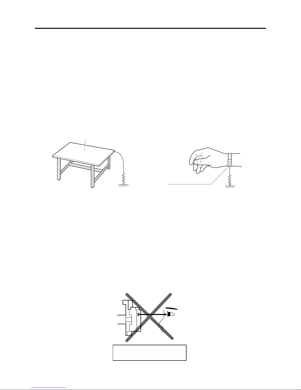
1-2 Electrostatic Protection Measures
Semiconductor components can be damaged by static electricity charged on clothes, human body,
etc. Take great care when handling components to avoid electrostatic damage, and perform
servicing in an environment where grounding is complete.
(1) Grounding work bench (Fig. 1-2-1)
Lay out an antistatic mat on work bench, and then use the ground plate to ground the work bench.
(2) Grounding human body (Fig. 1-2-2)
Use an antistatic wrist strap to discharge any static electricity charged on the body. Also, use a
tester for wrist strap to make sure that the wrist strap is working normally. Note, however, that
static electricity charged on clothes will not be discharged by wrist strap: Therefore do not allow
your clothes to touch the semiconductor components.
Antistatic mat
1M ohm
Antistatic wrist strap
Ground
Fig. 1-2-1 Grounding Work Bench Fig. 1-2-2 Grounding Human Body
1M ohm
1-3 Cautions When Handling DVD Drive
The optical pickup in DVD drive has a high precision structure: Be sure to observe the following
cautions.
1) Do not subject optical pickups to any severe vibrations or impact during movement, installation
or disassembly.
2) When performing repair work, do not perform disassembly any further than that described in
this manual.
3) Never turn the semi-variable resistors for adjustment in optical pickup or DVD drive.
4) NEVER look into the objective lens in optical pickup or directly view the laser light: You could
lose your eyesight.
Do not directly look at laser light
from pickup.
Fig. 1-3-1 Cautions on Optical Pickup
1 - 2
Safety Precaution for Repair > Lead-Free Solder
1-4 Lead-Free Solder
The printed circuit board that uses lead-free solder is adopted. To protect the global environment,
use the recommended lead-free solder also during servicing.
Read and observe the following before soldering:
Caution
ALWAYS wear protective goggles during soldering so that no solder smoke or scattered solder
enters the eye. Lead-free solder may scatter at high temperatures of 600°C.
(1) Identification of circuit boards that use lead-free solder
“F” is stamped or noted with pattern letter on circuit boards that use lead-free solder.
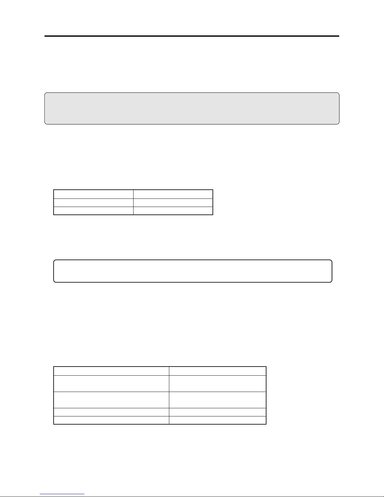
(2) Characteristics of lead-free solder
The components of lead-free solder used are as follows. The melting point of lead-free solder is 3040°C higher than that of lead based solder:
Point to be soldered
For reflow
For dip
Composition of alloy (wt%)
Solder paste: Sn-3Ag-0.5Cu
Bar solder: Sn-0.6Cu
Melting temperature: Approx. 220°C
(3) Lead-free solder for servicing
Use the following lead-free solder for servicing:
Recommended lead-free solder and composition of alloy (wt%): Sn-3.0Ag-0.5Cu or equivalent
Information:
For composition of alloy, Sn is tin; Ag is silver; Cu is copper; Bi is bismuth; Pb is lead.
(4) Soldering iron for servicing
The temperature of soldering iron tip must be adjusted according to the points to be soldered: Use
an antistatic soldering iron with thermal control function.
When removing components, take care not to damage any surrounding component or pattern. When
attaching components, observe the heating time in the following table so that the components are
not destroyed by heat.
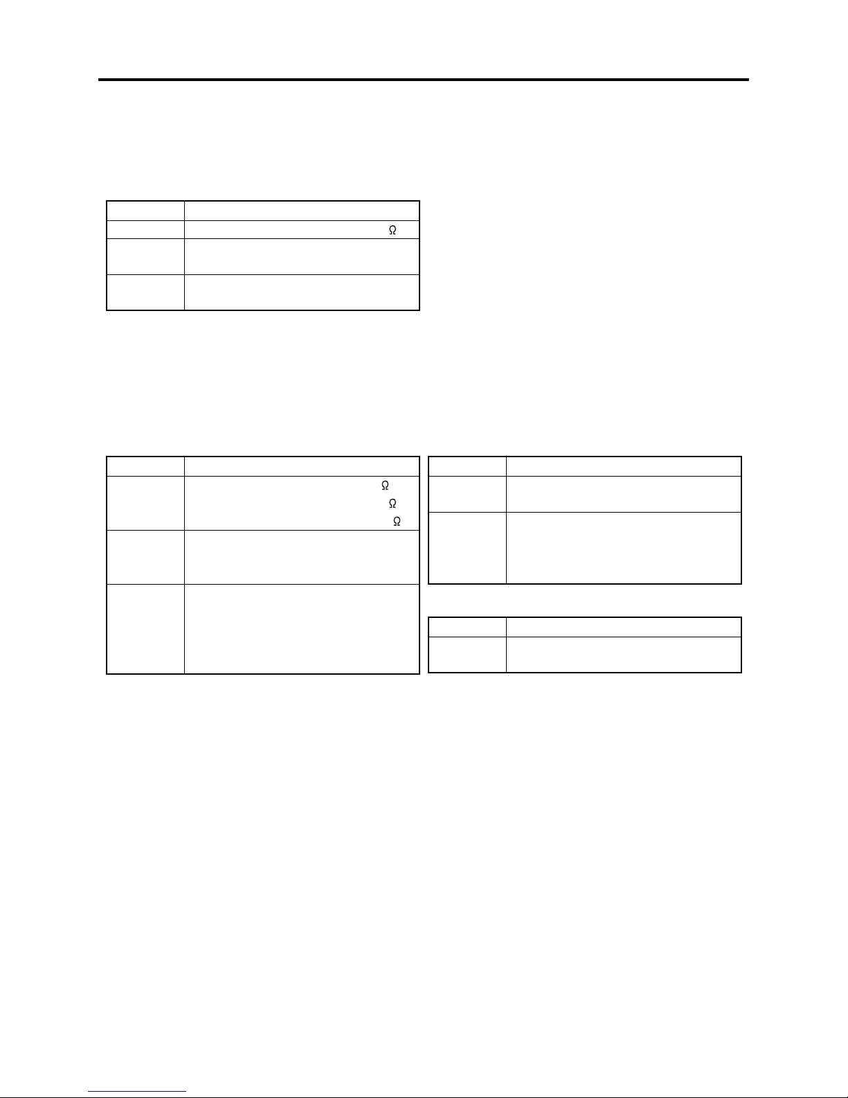
Tip temperatures for different soldering points:
Point to be soldered
Surface-mounted (chip) parts [other than
those shown below]
Surface-mounted (chip) parts [for DVD
cameras, cellular phones only]
Discrete parts
Chassis, metal shield, etc.
320 ± 30°C
[heating time: less than 5 seconds]
350 ± 10°C
[heating time: less than 3 seconds]
380 ± 30°C
420 ± 30°C
Tip temperature
1 - 3

Safety Precaution for Repair > Lead-Free Solder
(5) Cautions when using lead based solder
It is recommended that you use lead-free solder when servicing, but it is also possible to service
using lead based solder. However, if lead based solder is used for servicing, take care with the
following:
1) Before using lead based solder, remove the lead-free solder completely from the point to be
soldered.
2) For additional soldering for repair, set the soldering iron tip temperature for lead-free solder, mix
lead based solder and lead-free solder sufficiently. Do not perform any repair using the bare
soldering iron tip without adding solder, since it will cause secondary failure due to lack of
strength.
1 - 4
Safety Precaution for Repair > Notes When Using Service Manual
1-5 Notes When Using Service Manual
(1) Value units used in parts list
Certain symbols are indicated as shown below for value units of resistors, capacitors and coils in
parts list. When you read them, note the following regular indications:
Parts
Resistor
Capacitor
Coil
Indication in list Regular indication
KOHM
UF
PF
UH
MH
.........................................
................................................
................................................
...............................................
..............................................
k
µF
pF
µH
mH
(2) Values in schematic diagrams
The values, dielectric strength (power capacitance) and tolerances of the resistors (excluding
variable resistors) and capacitors are indicated in the schematic diagrams using abbreviations.
Certain symbols are indicated for value units: When you read them note the regular indications in
tables below:
[Resistors] [Capacitors]
Item
Value
Tolerance
Power
capacitance
No indication
..................................................
K
.................................................
M
No indication
(All tolerances other than ±5% are
indicated in schematic diagrams)
No indication
(1/16 W for leadless resistors with no
indication)
All capacitances other than the above
are indicated in schematic diagrams.
Indication
..............................
..............................
..............................
k
M
±5%
1/8W
Item
Value
Dielectric
strength
[Coils]
Item
Value
Indication
No indication
..................................................
P
No indication
(All dielectric strengths other than
50 V are indicated in schematic
diagrams)
..............................
..............................
µF
pF
50V
Indication
...................................................
µ
..................................................
m
µH
mH
(3) Identifications of sides A/B in circuit board diagrams
1) Board with a pattern on one side and parts on both sides:
Side A: Shows discrete parts, viewed from the pattern side.
Side B: Shows leadless parts, viewed from the pattern side.
2) Board with patterns on both sides and parts on both sides:
Side A: Shows parts and patterns which can be seen when the case is opened.
Side B: Shows parts and the pattern on the back of side A.
1 - 5
Safety Precaution for Repair > Notes When Using Service Manual
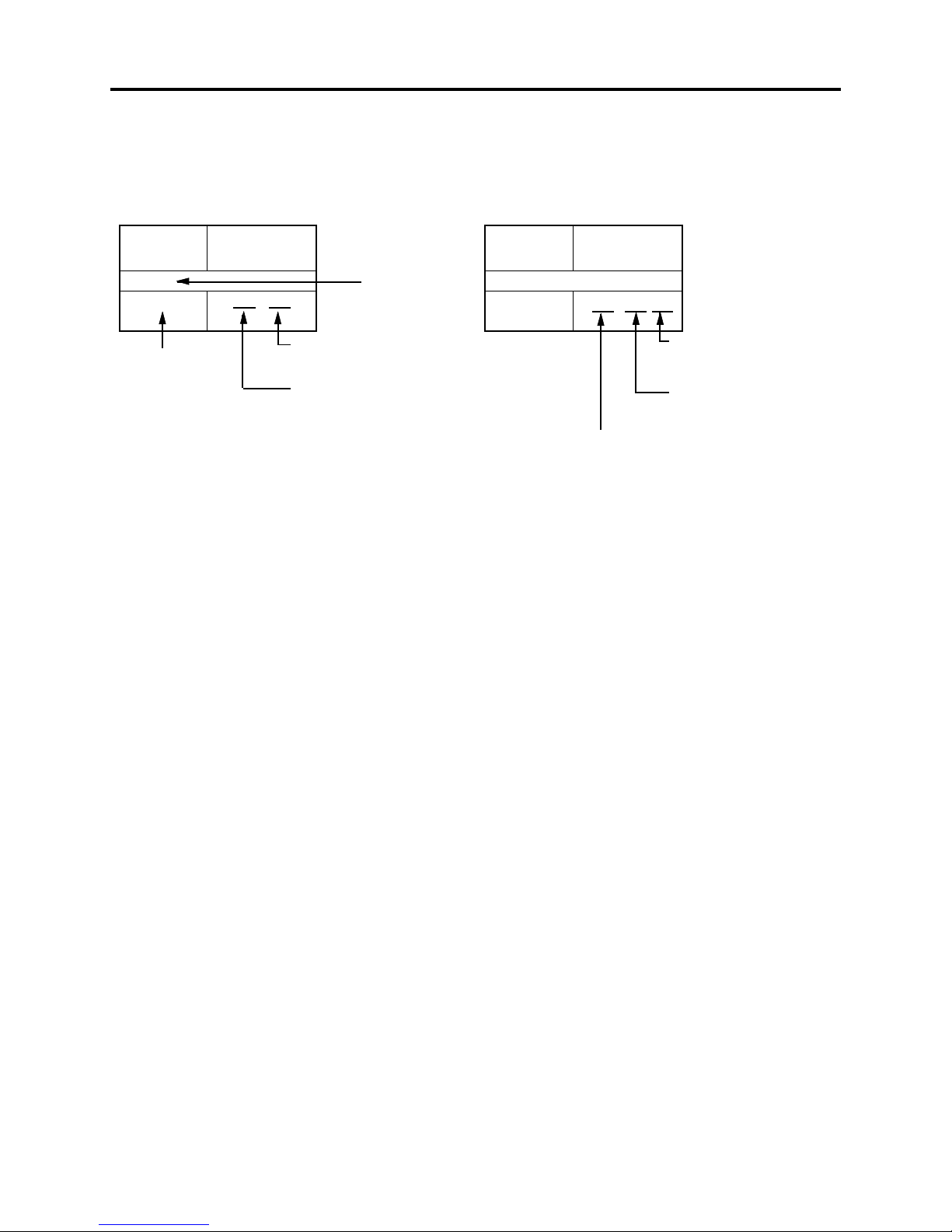
(4) Table for indexing locations of parts
This table shows locations of each part on circuit board diagrams. The locations are indicated using
the guide scales on the external lines of diagrams.
2) Two diagrams indicated for each board1) One diagram indicated for each board
Symbol
No.
IC
IC1201
Symbol no.
Parts
Location
2 A
Type of part
Zone "A" on circuit board
diagram
Zone "2" on circuit board
diagram
Symbol
No.
IC
IC1201
A: Shows side A
B: Shows side B
Parts
Location
A - 2 A
Zone "A" on board
diagram
Zone "2" on board
diagram
1 - 6
2
General Description
2-1 Overview
The DZ-MV580A DVD video camera/recorder has been made more compact than the previous DZMV380A; the DZ-MV550A has been made compact than the DZ-MV350A.
The DZ-MV580A has a CCD image sensor with a total of 1,020,000 pixels and a high-performance
optical 10-power zoom.
The DZ-MV550A has a CCD image sensor with a total of 680,000 pixels and an optical 18-power
zoom.
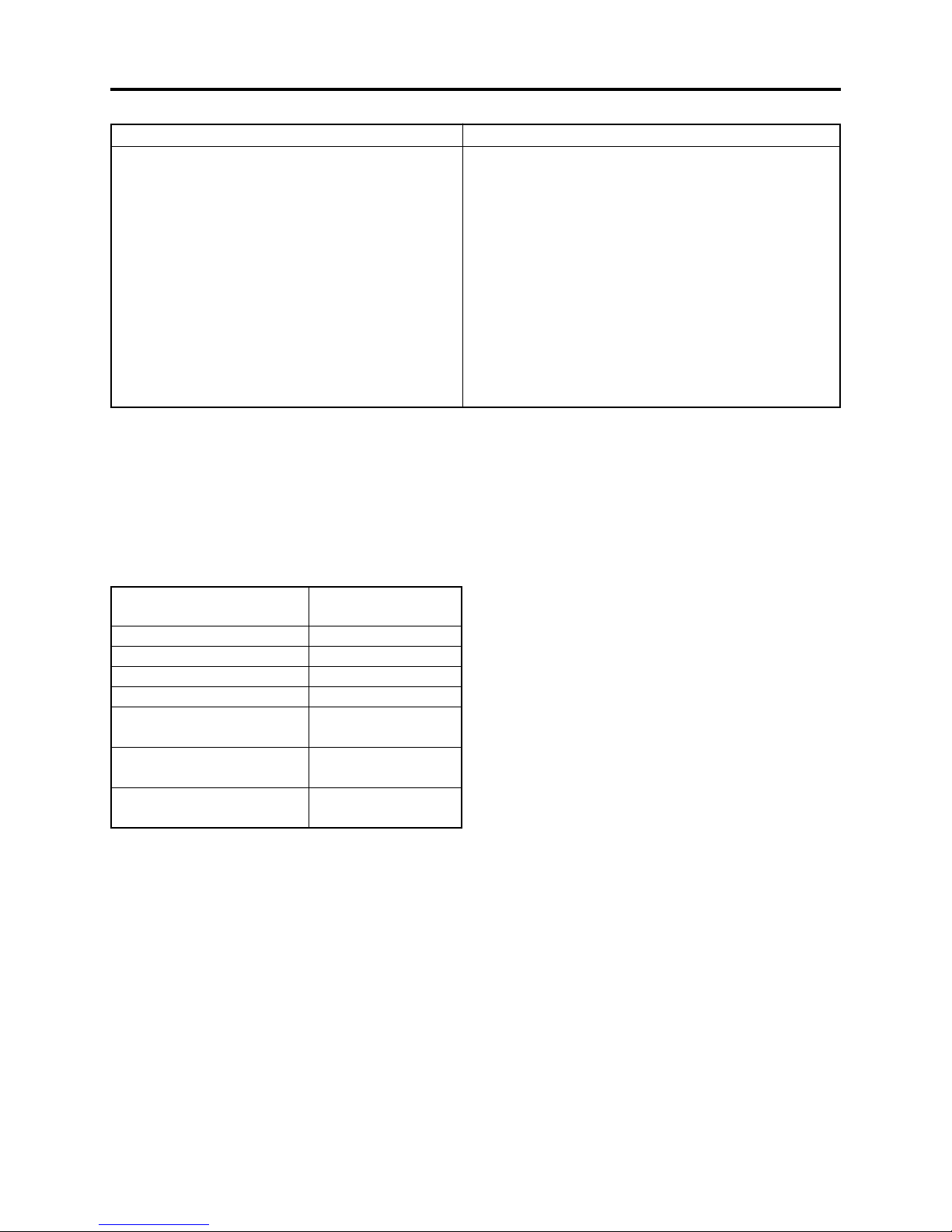
2-1-1 Servicing method
Refer to the following table and perform the designated, appropriate servicing. Any changes that
occur in the service method will be published using service bulletin, etc.
Do not perform any servicing other than that described in this manual.
Parts Name
Disc drive unit
Servicing method
Unit replacement.
Which incorporates the
DRV-R, MOD and HDM
DISC DRIVE
UNIT
FRT-H/FRT
CIRCUIT
BOARD
MR CIRCUIT BOARD
(In the LCD unit)
circuit boards.
Lens unit
AEL-H/AEL circuit
(*1)
board
DRF-H/DRF circuit
(*1)(*2)
board
FRT-H/FRT circuit
(*1)
board
GYR-H/GYR circuit
(*1)
board
LCD circuit board
MAN-H/MAN circuit
board(*1)
MR circuit board
SAF-H/SAF circuit
(*1)(*4)
board
SEN-H circuit board
(*1)(*5)
SHE-H/SHE circuit
(*1)
board
SWL2 circuit board
SWL3 circuit board
USB/USB-H circuit
(*1)
board
Unit replacement.
Component replacement.
Component replacement.
Component replacement.
Component replacement.
Component replacement.
Circuit board assembly
replacement.
(*3)
Component replacement.
Component replacement.
Component replacement.
Component replacement.
Component replacement.
Component replacement.
Component replacement.
LENS
UNIT
LCD
CIRCUIT
BOARD
SEN-H
CIRCUIT
BOARD
AEL-H/AEL
CIRCUIT
BOARD
GYR-H/GYR
CIRCUIT
BOARD
USB-H/USB
CIRCUIT
BOARD
Fig. 2-1-1
SHE-H/SHE
CIRCUIT
BOARD
SWL2
CIRCUIT
BOARD
SWL3-H/SWL3
CIRCUIT
BOARD
SAF-H/SAF
CIRCUIT
BOARD
*1: The board names suffixed with “-H” are for DZ-MV580A only.
*2: Film type board that connects MAN-H/MAN circuit board and disc drive unit.
*3: Film type board in LCD unit
*4: Film type board that connects AEL-H/AEL circuit board and SWL2 circuit board.
*5: Applicable only to DZ-MV580A. Although the SEN-H circuit board and lens unit in DZ-MV580A are
assigned as different boards, the circuit board in DZ-MV550A that corresponds to SEN-H is assembled
in the lens unit.
DRF-H/DRF
CIRCUIT
BOARD
MAN-H/MAN
CIRCUIT
BOARD
2 - 1
General Description > Features / Specifications
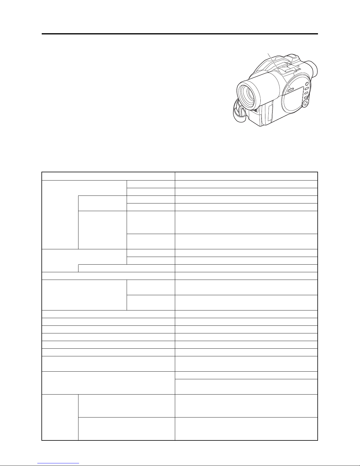
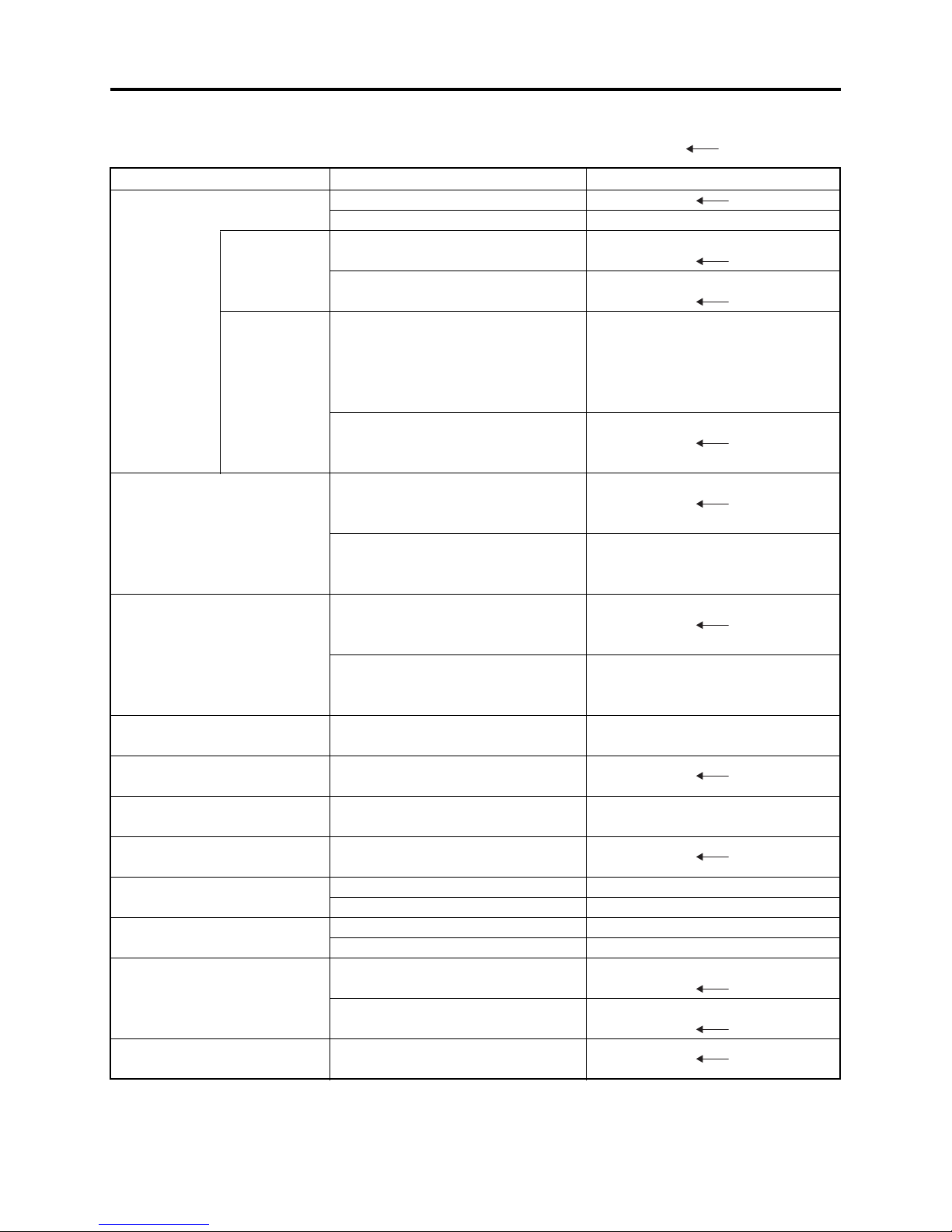
2-2 Features
QUICK MODE switch mounted
The new DVD video camera/recorder has a QUICK MODE switch
that switches the on-screen display between Quick mode and
Normal mode: The new timer of video camera/recorder can easily
operate the screen display in Quick mode.
The Quick mode displays only the fundamental menu items; a
brief explanation of the selected item is displayed across the
bottom of screen.
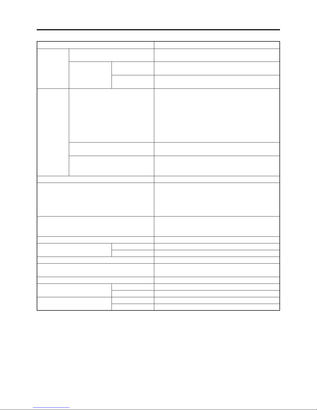
2-3 Specifications
Item
CCD Image Sensor
Total number of
pixels
Number of
effective pixels:
Lens
Filter diameter / Thread pitch:
Focus
Zoom
Required minimum illumination
Viewfinder
LCD monitor
Image Stabilizer
Shutter speed
Self-timer recording
External microphone jack
Recording mode
Maximum
time of
recordable
video
DVD-RAM disc (per side)
DVD-R disc (per side)
DZ-MV580A
DZ-MV550A
DZ-MV580A
DZ-MV550A
DZ-MV580A
DZ-MV550A
DZ-MV580A
DZ-MV550A
DZ-MV580A
DZ-MV550A
1/3.8-inch interlaced
1/6-inch interlaced
Approx. 1,020,000
Approx. 680,000
Video: Approx. 400,000
(Approx. 530,000 when 16:9 is set)
Photo: Approx. 960,000
Video: Approx. 340,000
Photo: Approx. 340,000
F1.8 - 2.4, f = 3/16” - 1-1/2” (3.8 - 38 mm)
F1.8 - 2.8, f = 1/16” - 1-1/2” (2.1 - 37.8 mm)
1-7/16” (37 mm) / 0.75mm
Auto/Manual
Optical 10×, 240× with digital zoom added (40× for
photo)
Optical 18×, 500× with digital zoom added (40× for
photo)
0.3 lx (When Low Light mode is selected)
0.33-inch color TFT (approx. 110,000 pixels)
2.5-inch color TFT (approx. 120,000 pixels)
Electronic Type
1/60 - 1/4000 second (video)
Photo recording only
Ø 3.5 mm stereo mini-jack
(a plug-in power type microphone cannot be used)
Video with audio (DVD-RAM disc, DVD-R disc)
Photo (DVD-RAM disc, SD memory card,
MultiMediaCard)
XTRA mode: Approx. 18 min.
FINE mode: Approx. 30 min.
STD mode: Approx. 60 min.
FINE mode: Approx. 30 min.
STD mode: Approx. 60 min.
LPCM mode: Approx. 30 min.
2 - 2
QUICK MODE SWITCH
Fig. 2-2-1
Specifications
General Description > Specifications
Maximum
number of
recordable
photos
Recording
format
Audio playback format
Recording media
Jacks
Battery system
Power consumption (when
recording with LCD monitor off )
Dimensions (W × H × D, excluding projections)
Operating temperature (humidity)
Storage temperature
Weight (without battery and
disc)
Total weight when recording
(when using DZ-BP14S battery)
DVD-RAM disc (per side)
SD memory
Card
(When using
32MB card)
DVD-RAM disc
DVD-R disc
Card
DZ-MV580A
DZ-MV550A
DZ-MV580A
DZ-MV550A
DZ-MV580A
DZ-MV550A
DZ-MV580A
DZ-MV550A
SpecificationsItem
999 However, if video and photo are mixed on one disc,
the recordable number will decrease
Approx. 50 (in FINE mode) Varies depending on the
recording quality and the type of card
Approx. 220 (in FINE mode) Varies depending on the
recording quality and the type of card
Video: Conforming to DVD video recording
(DVD-VR) format
Audio: MPEG Audio layer 2
Photo: Simultaneous recording, conforming to JPEG
format (DZ-MV580A: 1280 × 960 pixels, DZ-
MV550A: 640 × 480 pixels) and DVD video
recording (DVD-VR) format (704 × 480 pixels).
[JPEG of external input: 640 × 480 pixels]
Video: Conforming to DVD video format
Audio: MPEG Audio layer 2 or LPCM
Photo: Conforming to JPEG (DZ-MV580A: 1280 × 960
pixels, DZ-MV550A: 640 × 480 pixels) format
[External input: 640 × 480 pixels]
MPEG Audio layer 2, LPCM, Dolby AC3
8 cm DVD-RAM disc (conforming to DVD-RAM Ver. 2.1)
8 cm DVD-R disc
(conforming to DVD-R for General Ver. 2.0)
SD memory card
MultiMediaCard
Video/audio input/output × 1
External microphone input × 1
PC connection terminal (connected to PC USB port) × 1
Lithium-ion
Approx. 4.4 W (DVD-RAM disc used, FINE mode)
Approx. 4.1 W (DVD-RAM disc used, FINE mode)
Approx. 2-1/2” × 3-1/2” × 5-3/4” (64 × 89 × 146 mm)
32-104°F (0-40°C) (less than 80%)
32-86°F (0-30°C) when connected to PC
-4 - 104°F (-20 - 60°C)
Approx. 500 g
Approx. 490 g
Approx. 585 g
Approx. 575 g
*1
2 - 3
General Description > Specifications
SpecificationsItem
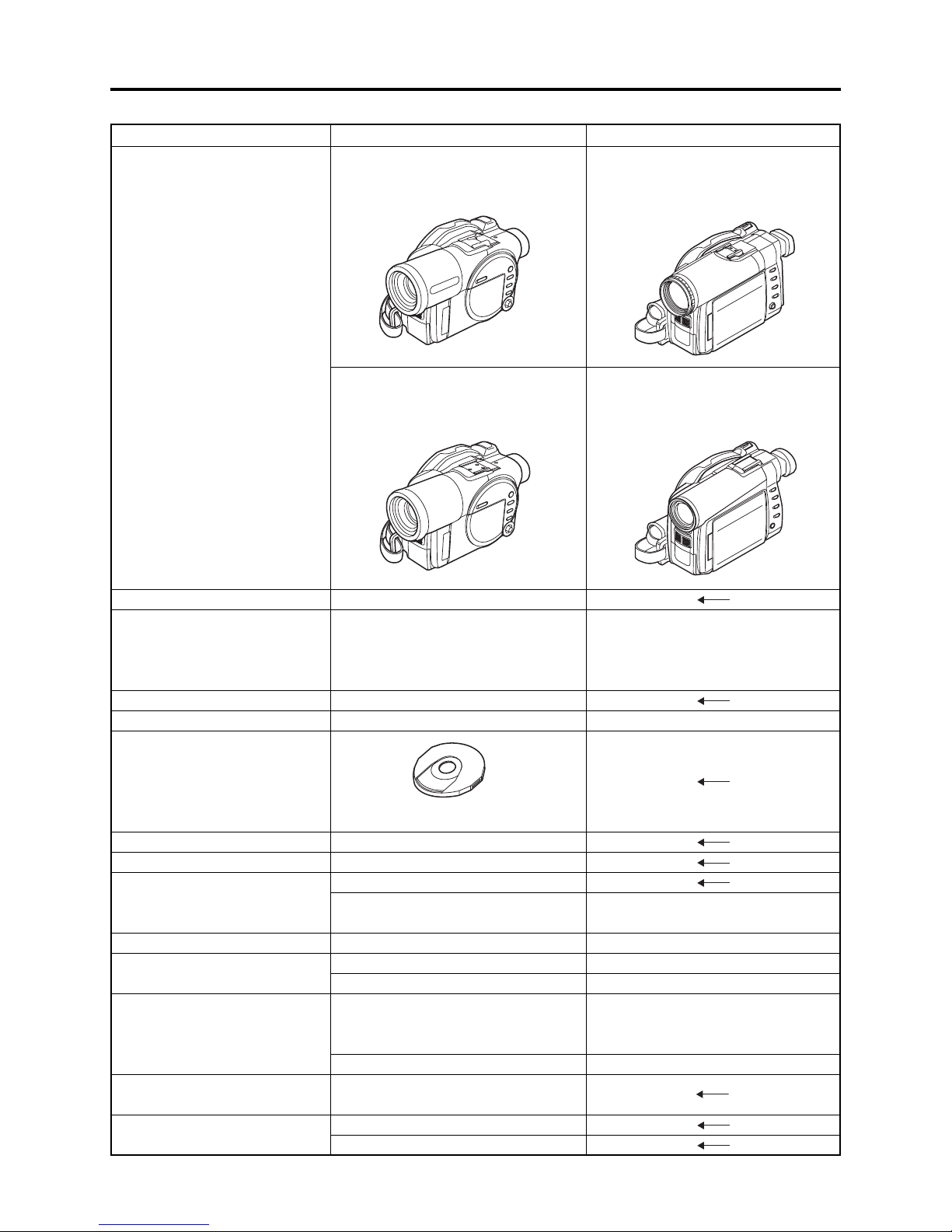
Provided accessories AC adapter/charger (model DZ-ACS1)
Power cable
DC power cord,
Battery (model DZ-BP14S)
AV/S input/output cable
Infrared remote control (model DZ-RM3W)
Lithium battery for remote control (model CR2025)
Lens cap
Lens cap string
Shoulder strap
Software CD-ROM
PC connection cable
Single-sided 8cm DVD-RAM disc (in round DVD holder)
*1: The DZ-MV580A/MV550A records audio on DVD-R disc using the MPEG Audio layer 2 format in FINE
or STD mode, and using the LPCM format in LPCM mode.
The MPEG Audio layer 2 format is an option of DVD video standard. Record a DVD-R disc in LPCM
mode to play it back on a DVD player that does not comply with this option standard.
Specifications are subject to change without notice for the purpose of improvement.
Specifications of DZ-ACS1 AC Adapter/Charger
Power supply
Input capacity
DC output (max.)
Charge output
Weight
External dimensions
(W x H x D)
Ambient temperature for
operation
Allowable relative
humidity
100 - 240 V AC,
50/60 Hz
26 VA (at 100 V)
7.9 V, 1.4 A
8.4 V, 0.65A
105 g
61 × 32 × 91 mm
32 - 104°F (5 - 35°C)
40 - 80%
2 - 4
General Description > Major Differences from Previous Models
2-4 Major Differences from Previous Models
: Same as on left
Item
CCD
Total number
of pixels
Number of
effective pixels
Lens
Zoom
Filter diameter
Required minimum
illumination
Viewfinder
LCD monitor
Power consumption
Weight
Accessory Shoe
PC connection terminal
[USB standard]
DZ-MV580A/MV550A
DZ-MV580A: 1/3.8-inch interlaced
DZ-MV550A: 1/6-inch interlaced
DZ-MV580A:
Approx. 1,020,000 pixels
DZ-MV550A:
Approx. 680,000 pixels
DZ-MV580A:
Video: Approx. 400,000 pixels
(Approx. 530,000 when
16:9 is set)
Photo: Approx. 960,000 pixels
DZ-MV550A:
Video: Approx. 340,000
Photo: Approx. 340,000
DZ-MV580A:
F1.8 - 2.4
f = 3/16” - 1-1/2” (3.8 - 38 mm)
DZ-MV550A:
F1.8 - 2.8
f = 1/16” - 1-1/2” (2.1 - 37.8 mm)
DZ-MV580A:
Optical 10×, 240× with digital zoom
added (40× for photo)
DZ-MV550A:
Optical 18×, 500× with digital zoom
added (40× for photo)
1-7/16” (37 mm)
0.3 lx
(When Low Light mode is selected)
0.33-inch color TFT
(approx. 110,000 pixels)
2.5-inch color TFT
(approx. 120,000 pixels)
DZ-MV580A: Approx. 4.4 W
DZ-MV550A: Approx. 4.1 W
DZ-MV580A: Approx. 500 g
DZ-MV550A: Approx. 490 g
DZ-MV580A: Power/Control terminal
provided
DZ-MV550A: Power/Control terminal
not provided
Type mini-B
[USB 2.0]
DZ-MV380A/MV350A
DZ-MV380A:
DZ-MV350A: 1/4-inch interlaced
DZ-MV380A:
DZ-MV350A:
DZ-MV380A:
Video: Approx. 400,000 pixels
Photo: Approx. 960,000 pixels
DZ-MV350A:
DZ-MV380A:
DZ-MV350A:
F1.8 - 2.5
f = 1/8” - 1-1/4” (3.15 - 31.5 mm)
DZ-MV380A:
DZ-MV350A:
Optical 10×, 240× with digital zoom
added (40× for photo)
DZ-MV380A: 1-7/16” (37 mm)
DZ-MV350A: 1-3/16” (30.5 mm)
0.44-inch color TFT
(approx. 110,000 pixels)
DZ-MV380A: Approx. 5.0 W
DZ-MV350A: Approx. 4.7 W
DZ-MV380A: Approx. 505 g
DZ-MV350A: Approx. 480 g
DZ-MV380A:
DZ-MV350A:
2 - 5
General Description > Major Differences from Previous Models
Item DZ-MV580A/MV550A DZ-MV380A/MV350A
Dimensions (W × H × D) and
shape
DZ-MV580A:
Approx. 2-1/2” × 3-1/2” × 5-3/4”
(64 × 89 × 146 mm)
DZ-MV380A:
Approx. 2-3/8” × 3-11/16” × 5-13/16”
(60 × 93 × 148 mm)
AC adapter/charger
Battery pack
Infrared remote control
AV input/output jack
Shape of DVD holder
PC editing kit
Disc protect
EIS function
QUICK MODE switch
S-Video input function
16:9 function
Number of pixels for video
(MPEG2)
Number of pixels for JPEG
photo during camera recording
DZ-MV550A:
Approx. 2-1/2” × 3-1/2” × 5-3/4”
(64 × 89 × 146 mm)
DZ-ACS1
Provided: DZ-BP14S
(7.2V/1360mA)
Optional: DZ-BP14SW
(7.2V/1360mA)
DZ-RM3W
Pin 8 type
Round DVD holder
Provided
Software disc-protect
DZ-MV580A: Video mode only
DZ-MV550A: Video and photo
mode
Provided
DZ-MV580A: Provided
DZ-MV550A: Not provided
DZ-MV580A: Provided
(When using DVD-
RAM disc)
DZ-MV550A: Not provided
XTRA/FINE: 704 × 480 pixels
STD/LPCM: 352 × 480 pixels
DZ-MV580A: 1280 × 960 pixels
DZ-MV550A: 680 × 480 pixels
DZ-MV350A:
Approx. 2-1/4” × 3-1/2” × 5-1/4”
(57 × 89 × 132 mm)
Provided: DZ-BP14S
(7.2V/1360mA)
Optional: DZ-BP14SW
(7.2V/1360mA)
Pin 10 type
DZ-MV350A: Video mode only
Not provided
DZ-MV380A: Provided
DZ-MV350A: Not provided
DZ-MV380A: Not provided
DZ-MV350A: Not provided
2 - 6
General Description > Major Differences from Previous Models
Item DZ-MV580A/MV550A DZ-MV380A/MV350A
Number of pixels for MPEG
photo during camera recording
(When using disc)
Number of pixels for photo
during line-input recording
File size of photo
704 × 480 pixels
JPEG: 640 × 480 pixels
MPEG: 704 × 480 pixels
DZ-MV580A:
FINE: Approx. 512KB
NORM: Approx. 384KB
ECO: Approx. 256KB
DZ-MV550A:
FINE: Approx. 128KB
NORM: Approx. 64KB
ECO: Approx. 32KB
DZ-MV380A:
DZ-MV350A:
2-5 Compatibility of Recorded Discs
Discs recorded or edited on DZ-MV580A/MV550A can also be recorded, edited and played back on
other DVD video camera/recorders, except for those for which disc-protect
Discs recorded or edited on other DVD video camera/recorders can also be recorded, edited and
played back on DZ-MV580A/MV550A: However, the DZ-MV100A cannot handle DVD-R disc, and a
scene memo recorded on the DZ-MV100A Disc Navigation function cannot be played back or edited
on another DVD video camera/recorder.
*1: The DZ-MV380A/MV350A can release the disc-protect that has been set on DZ-MV580A/MV550A.
Therefore, if the disc-protect set on DZ-MV580A/MV550A is released, the discs can be recorded, edited
and played back on DZ-MV380A/MV350A.
(*1)
has been set.
2 - 7

General Description > Names of Parts
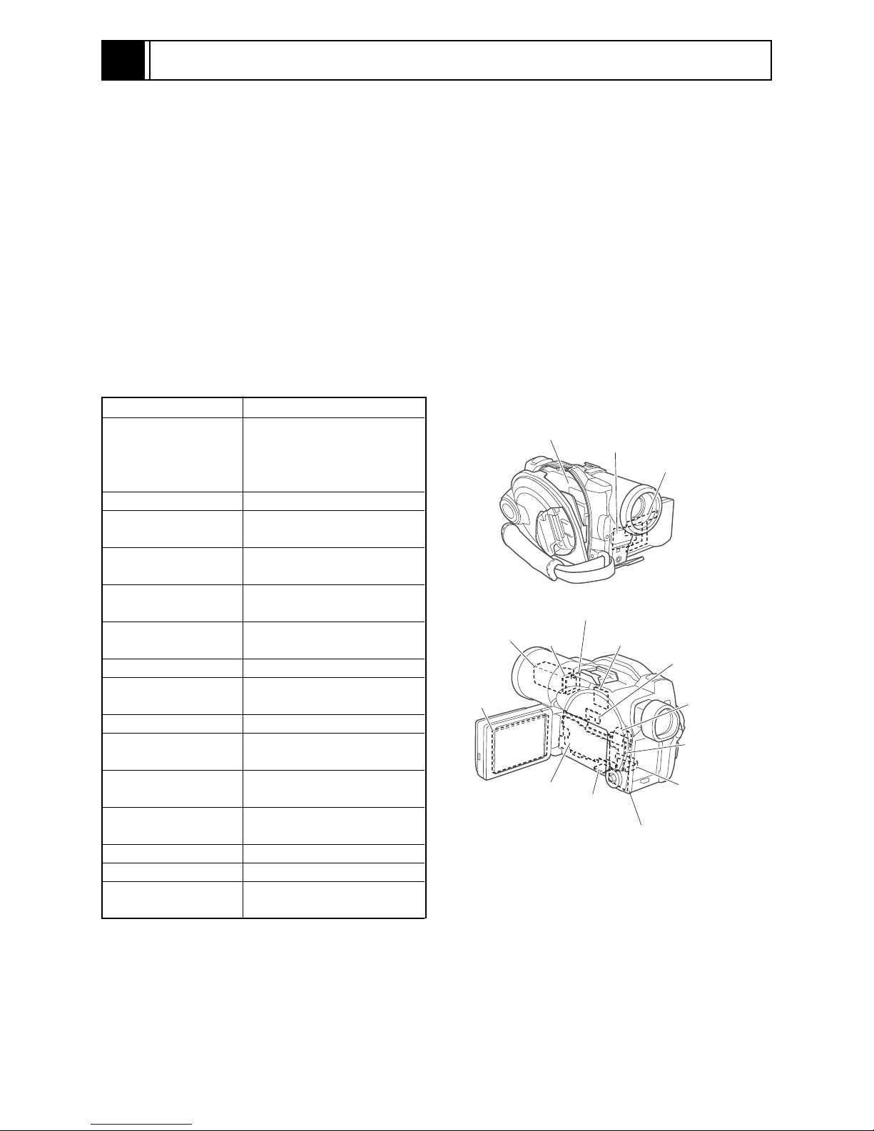
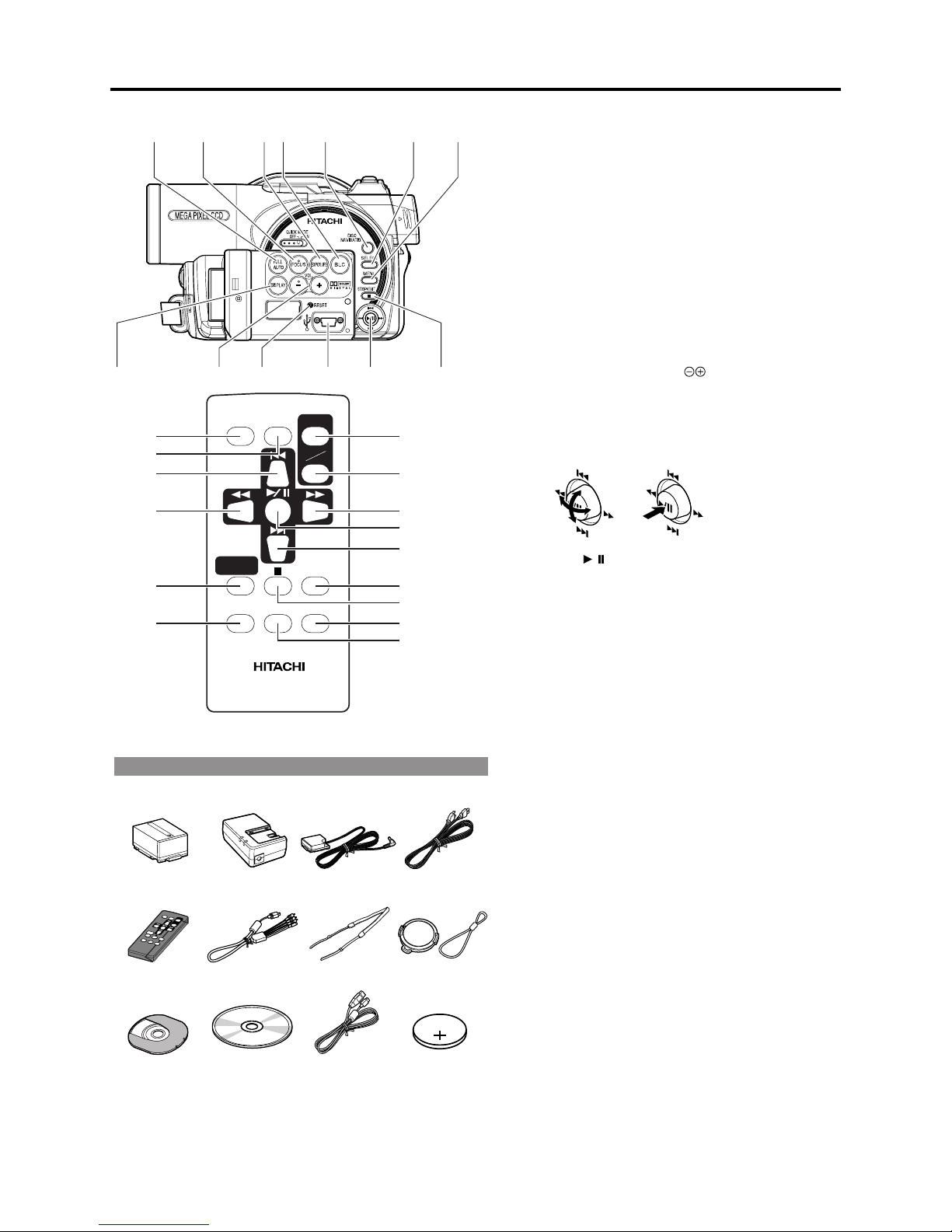
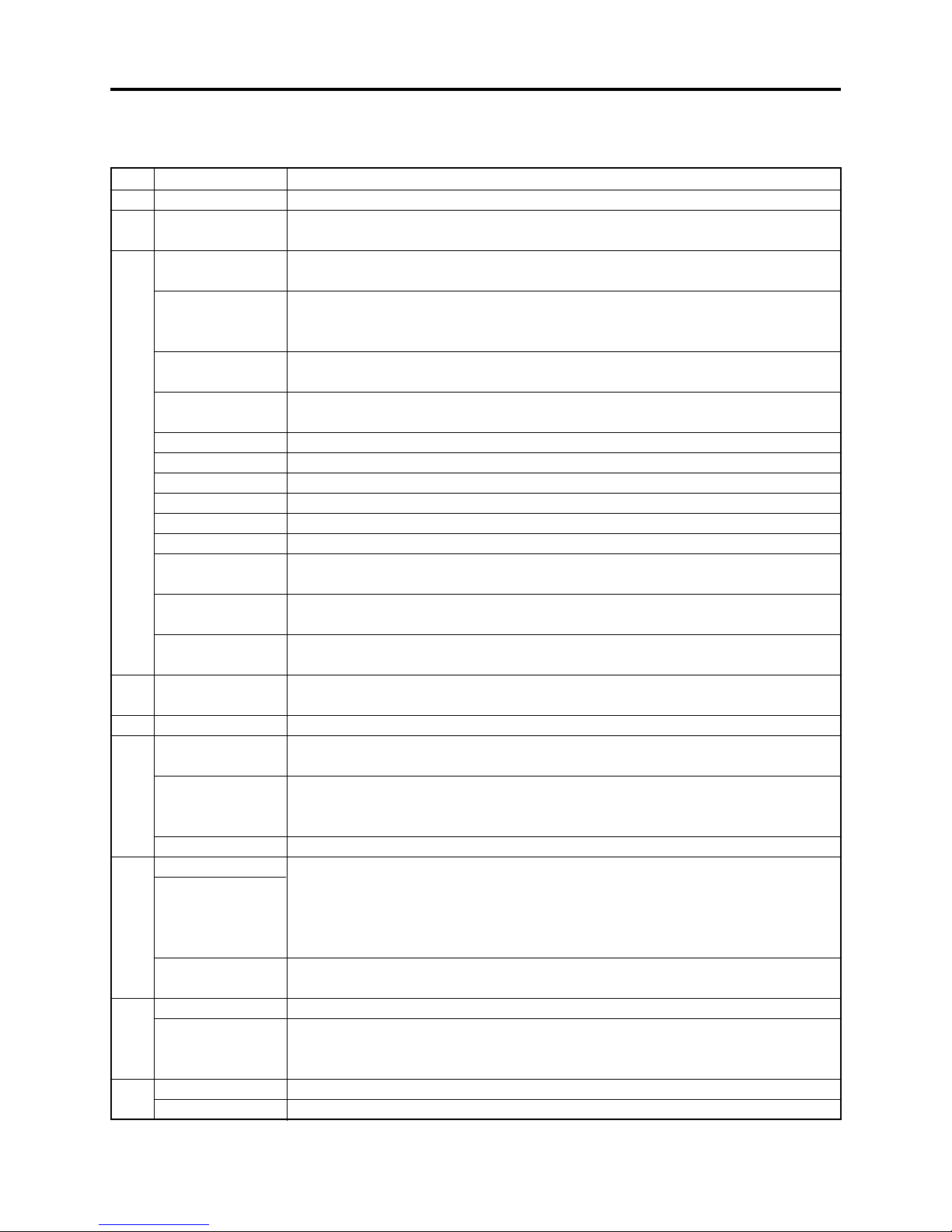
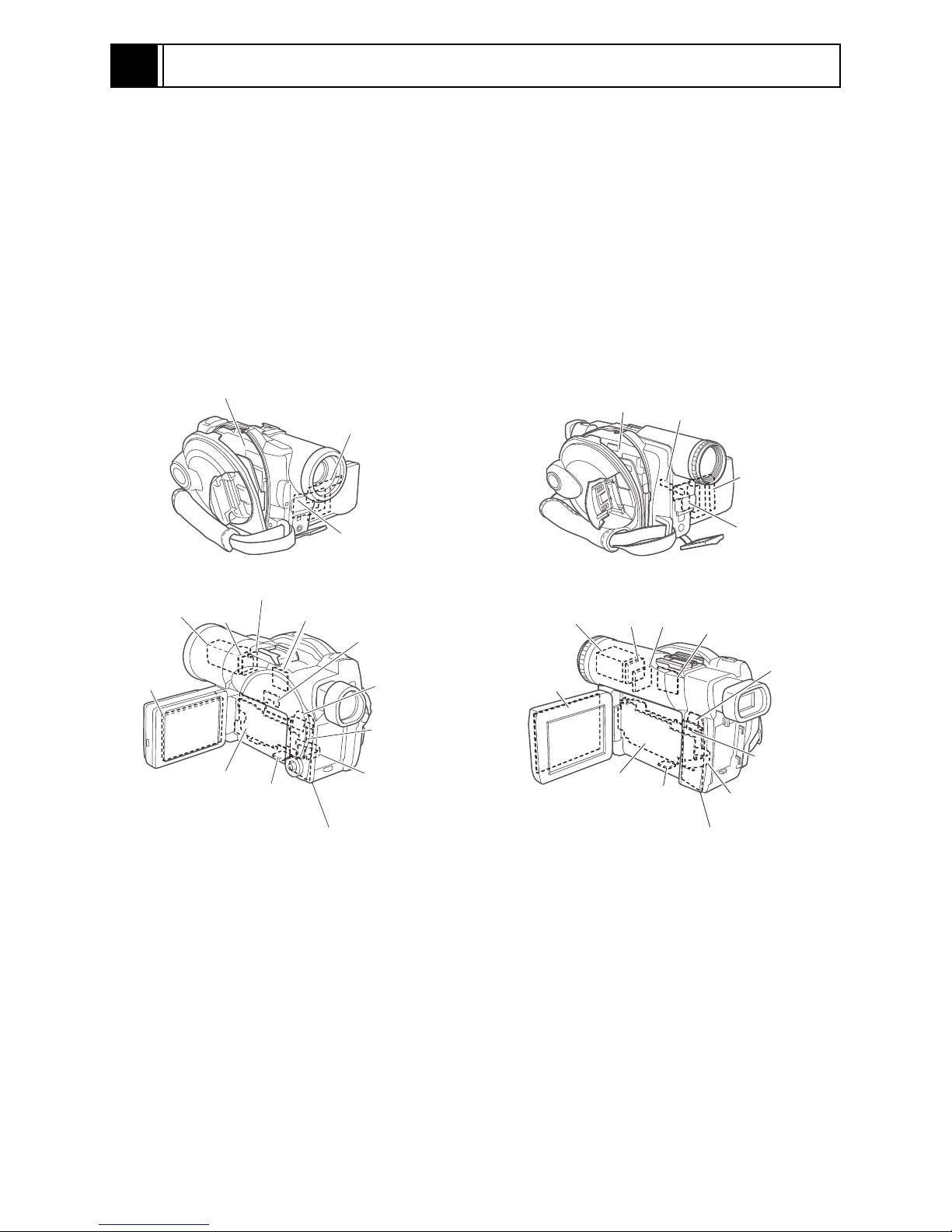
2-6 Names of Parts
578
910
A/V
2
13 4
Although the external appearances of DZ-MV550A
and DZ-MV580A are different, the
method of operating both models is identical.
DZ-MV580A illustrations are used in this
manual.
14 15 16 2017
21 22 24 2625
MIC
(Inside the cover)
23
18
6
11 12
19
BATTERY EJECT
(Bottom)
1 Infrared receiver
When the remote control is used to operate the
DVD video camera/recorder, this receiver will
receive the infrared signal.
2 Lens cap string attachment hole
3 Recording indicator
The red indicator will light during recording.
4 Stereo microphone
5 Optical 18x zoom lens (DZ-MV550A)
Optical 10x zoom lens (DZ-MV580A)
6 Lens hood
Always remove this lens hood when using
generally available tele-conversion or wideconversion lens.
7 Zoom lever
Push the lever to the T side for telephoto, or
to the W side for wide-angle.
8 Accessory shoe
13
Only for DZ-MV580A:
The optional video flash, etc. can be attached
here. (See the instruction manual of device to be
attached for details.)
9
External microphone jack
AV input/output jack
10
11 2.5" type liquid crystal display (inside)
12 QUICK MODE switch
To switch the menu display on screen between
Advanced mode and Quick mode.
13 BATTERY EJECT switch
The BATTERY EJECT switch is located on the
bottom of this DVD video camera/recorder:
Slide it when removing the battery.
14 Viewfinder
15 Diopter control
To adjust the focus of image appearing in the
viewfinder. (Pull out the viewfinder.)
16 ACCESS/PC indicator
Will blink or light when the disc in DVD video
camera/recorder is accessed (write or read is
executed) or the DVD video camera/recorder
is connected to PC.
17 DISC EJECT button
Press down and release this button to open the
disc guide.
18 Disc insertion block
19 CARD ACCESS indicator
20 Card insertion block
21 Battery attachment platform
22 Record button
23 Power switch
24 LOCK switch
It is recommended that you set the LOCK
switch to (to the left) to prevent the power
switch in the " VIDEO" position from
accidentally moving to " PHOTO".
25 Speaker
26 Hand strap
2 - 8
General Description > Names of Parts
27 28 29 30 31 32 33
DIGITAL
ZOOM
DZ-RM3W
ZOOM
T
DISPLAY
DELETESELECT
W
40
41
42
43
44
45
* The buttons on remote control will function the same as
those on DVD video camera/recorder.
REC
DISC
NAVIGATION
MENU
Accessories
Battery
(model: DZ-BP14S)
AC adapter/
chargre
(model: DZ-ACS1)
DC power cord AC power cable
27 FULL AUTO button
To switch the DVD video camera/recorder to full automatic.
28 FOCUS button
To switch between manual focus and autofocus.
29 EXPOSURE button
Press this button to adjust the exposure.
30 BLC (backlight compensation) button
Press this button when subject is being lighted from rear.
31 DISC NAVIGATION button
32 SELECT button
33 MENU button
Press this button to display the menu for setting camera functions
and Disc Navigation.
34 DISPLAY (Screen display) button
Press this button to display the details of image being played back
or camera setting status, or switch the display off.
Volume control buttons (VOL)/ buttons
3935 36 37 3834
46
47
48
49
50
51
52
53
54
35
To adjust the volume of sound from speaker, etc.
36 RESET button
To reset all settings to defaults (status when the DVD video
camera/recorder was shipped from the factory)
37 PC connection terminal
38 Joystick
Move the joystick to select a scene or menu item, and then press
the center ( ) to play back the scene, pause it, or designate
an option of the menu.
39 Stop/cancel button
To end playback or cancel setting of menu.
40 REC button
41 DIGITAL ZOOM button
42 Reverse skip button
43 Reverse search button
44 DISC NAVIGATION button
45 MENU button
46 ZOOM T button
47 ZOOM W button
48 Forward search button
49 Play/pause button
50 Forward skip button
51 DISPLAY button
52 Stop button
53 DELETE button
54 SELECT button
/
Infrared remote
control
(Model: DZ-RM3W)
Single-side 8 cm
DVD-RAM disc
(in Round DVD
Holder)
AV/S input/output
cable
Software CD-ROM PC connection
Shoulder strap Lens cap and lens
cable
cap string
Lithium battery
(model CR2025)
2 - 9
General Description > List of Abbreviations and Terms for DVD Video Camera/Recorders
2-7 List of Abbreviations and Terms for DVD Video
Camera/Recorders
Index
Abbreviation/Term
A
AC3
C
CPRM
D
DCF
Dolby AC3
DPOF
DVD
DVD Forum
DVD-Audio
DVD-R
DVD-RAM
DVD-ROM
DVD-RW
DVD-Video
DVD Video
Format
DVD Video
Recording Format
E
Exif
F
FireWire
I
IEEE1394
Interlaced CCD
i-LINK
J
JEIDA
JEITA
JPEG
L
LCD
LPCM
M
MMC
MMCA
Explanation
See Dolby AC3.
Content Protection for Recordable Media: Copyright protection function that is
suitable for online distribution of music.
Design rule for Camera File system standard: This camera file system standard,
established by JEIDA (now merged to JEITA).
Audio coding format developed by Dolby Laboratories in U.S, also simply referred
as AC3 format: Supports 5-channel full-range sound and one channel for sub-woofer
sound playback.
Digital Print Order Format: DPOF allows user to record print information along
with photos on storage media to facilitate printing of photos.
Digital Versatile Disc. A huge amount of digital data for video (movie) and audio
can be recorded on this disc, whose size is the same as CD.
International organization that formulates the technical standards of DVD
One type of DVD standard disc, on which high-quality audio can be recorded
One type of DVD standard disc, to which writing once is possible (recordable type)
One type of DVD standard disc, to which writing up to 100,000 times is possible
One type of DVD standard disc, to which data for computer can be recorded
One type of DVD standard disc, to which writing up to 1000 times is possible
One type of DVD standard disc, on which high-quality video and audio can be
recorded
Video recording/playback standard that applies to DVD-Video, DVD-R and DVDRW
Video recording/playback standard that applies to DVD-RAM and DVD-RW: This
allows versatile editing functions, differing from the DVD Video Format.
Exchangeable image file format. File format used for recording photos on digital
cameras, established by JEIDA (now merged to JEITA).
See IEEE1394.
Also referred to as FireWire or i-LINK: Standard for serial interface that connects
PC and peripheral devices
This CCD scans one image twice (scans roughly once and interpolates between first
scanning lines the second time) and interlaces the images obtained by scanning
twice to create a one-image signal.
See IEEE1394.
JEIDA stands for Japan Electronic Industry Development Association.
JEITA stands for Japan Electronics and Information Technology Industries
Association, which came into existence when JEIDA merged with EIAJ (Electronic
Industries Association of Japan).
JEITA has established Exif and DCF standard.
Joint Photographic Expert Group: International standard format for compressing
still images
Liquid Crystal Display. LCD formats include STN and TFT.
Linear Pulse Code Modulation. Also referred to as linear PCM. LPCM is a format
that digitizes analog audio data during recording and converts it to analog data
during playback.
See MultiMediaCard.
See MultiMediaCard Association.
2 - 10
General Description > List of Abbreviations and Terms for DVD Video Camera/Recorders
Index Abbreviation/Term Explanation
M
MPEG
MPEG Audio
Layer 2
MultiMediaCard
MultiMediaCard
Association
OSTA
O
S
SCSI
SDA
SD Card
Association
SDMI
SD Memory Card
SecureMMC
Secure
MultiMediaCard
Software discProtect
STN LCD
T
TFT LCD
U
UDF
USB
V
VBR
Motion Picture Experts Group: Standard related to compression of digital video and
audio. MPEG2 is a higher standard of MPEG and is applied to video (movie)
requiring higher quality.
One of three audio compression standards (layers 1-3) defined by MPEG
Also referred to as MMC. Compact memory card, 32 mm long × 24 mm wide × 1.4
mm thick
Also referred to as MMCA. This association promotes the widespread use of
multimedia cards.
Optical Storage Technology Association, which is an international industry
organization that promotes recordable optical storage used to store computer data
and images.
Small Computer System Interface: A standard for connecting computer and
peripheral devices. Frequently notated by prefixing or suffixing the number that
indicates the data transfer rate, and First, Ultra, Wide, etc., to SCSI.
See SD Card Association.
Also referred to as SDA. This organization promotes the popularization of SD
memory card.
Secure Digital Music Initiative: This conference was established by hardware
makers, the Recording Industry Association of America (RIAA) and music industry
companies, to protect copyrights of musical compositions.
Formally named Secure Digital Memory Card. This compact memory card, 32 mm
long × 24 mm wide × 2.1 mm thick, is equipped with an advanced copyright
protection function.
See Secure MultiMediaCard.
Also referred to as SecureMMC. This compact memory card has multimedia card
specifications, to which an advanced copyright protection function is added.
Unusable on the DVD video camera/recorder.
This function writes the protect information to DVD-RAM disc to prevent accidental
erasure. Software Disc-Protect is included in DVD-RAM disc specifications defined
by DVD Forum.
Super-Twisted Nematic Liquid Crystal Display: This type of color LCD is inferior to
TFT LCD in coloring, view angle, etc.
Thin Film Transistor Liquid Crystal Display: This type of color LCD features clear
display, high contrast, wide view angle, etc.
Universal Disc Format, which is a file format of recordable disc defined by OSTA.
The version 2.01 UDF is used on DVD video camera/recorder.
Universal Serial Bus: Standard of serial interface that connects PC and peripheral
devices. Two versions - USB1.1 and USB2.0, with different data transfer rates exist at present.
Stands for Variable Bit Rate: This format of coding audio and video varies the
amount of data depending on the subject image.
2 - 11
3
Description of Operation
3-1 Description of Structure
(1) Configuration and locations of circuit boards
The configuration of circuit boards in DZ-MV580A/MV550A and their locations are very similar to
those in the base models DZ-MV380A/MV350A, except for whether the FAF circuit board is
provided or not.
The DZ-MV380A/MV350A had the FAF circuit board between the FRT and AEL circuit boards:
The DZ-MV580A/MV550A does not have this, since the FRT-H/FRT circuit board is directly
connected to AEL-H/AEL circuit board.
LENS
UNIT
LCD
CIRCUIT
BOARD
DISC DRIVE
UNIT
SEN-H
CIRCUIT
BOARD
AEL-H/AEL
CIRCUIT
BOARD
DZ-MV580A
GYR-H/GYR
CIRCUIT
BOARD
USB-H/USB
CIRCUIT
BOARD
MR CIRCUIT
BOARD
(In the LCD unit)
FRT-H/FRT
CIRCUIT
BOARD
SHE-H/SHE
CIRCUIT
BOARD
SWL2
CIRCUIT
BOARD
SWL3-H/SWL3
CIRCUIT
BOARD
DRF-H/DRF
CIRCUIT
BOARD
MAN-H/MAN
CIRCUIT
BOARD
SAF-H/SAF
CIRCUIT
BOARD
Fig. 3-1-1
LENS
UNIT
LCD
CIRCUIT
BOARD
DISC
DRIVE
UNIT
SEN
CIRCUIT
BOARD
AEL
CIRCUIT
BOARD
DZ-MV380A
FAF
CIRCUIT
BOARD
GYR
CIRCUIT
BOARD
USB
CIRCUIT
BOARD
SHE
CIRCUIT
BOARD
Circuit board
equivalent to
SWL2
MR CIRCUIT
BOARD
(In the LCD unit)
FRT
CIRCUIT
BOARD
DRF
CIRCUIT
BOARD
MAN
CIRCUIT
BOARD
SAF
CIRCUIT
BOARD
3 - 1
Description of Operation > Description of Structure / Description of Newly Adapted Technology
(2) Differences in structure between DZ-MV580A and DZ-MV550A
There are two major differences in structure between DZ-MV580A and DZ-MV550A:
1) Accessory shoe
The accessory shoe on DZ-MV580A has a power/control terminal, but the accessory shoe on DZMV550A doesn’t.
2) Lens unit
The lens unit in DZ-MV550A includes the cushion, crystal filter, CCD image sensor and SEN-H
circuit board, which are discrete from the lens unit in DZ-MV580A.
CCD
LENS
UNIT
IMAGE
SENSOR
CRYSTAL
FILTER
CUSHION
SEN-H
CIRCUIT
BOARD
LENS
UNIT
Circuit board equivalent
to SEN-H
DZ-MV580A LENS UNIT
DZ-MV550A LENS UNIT
Fig. 3-1-2
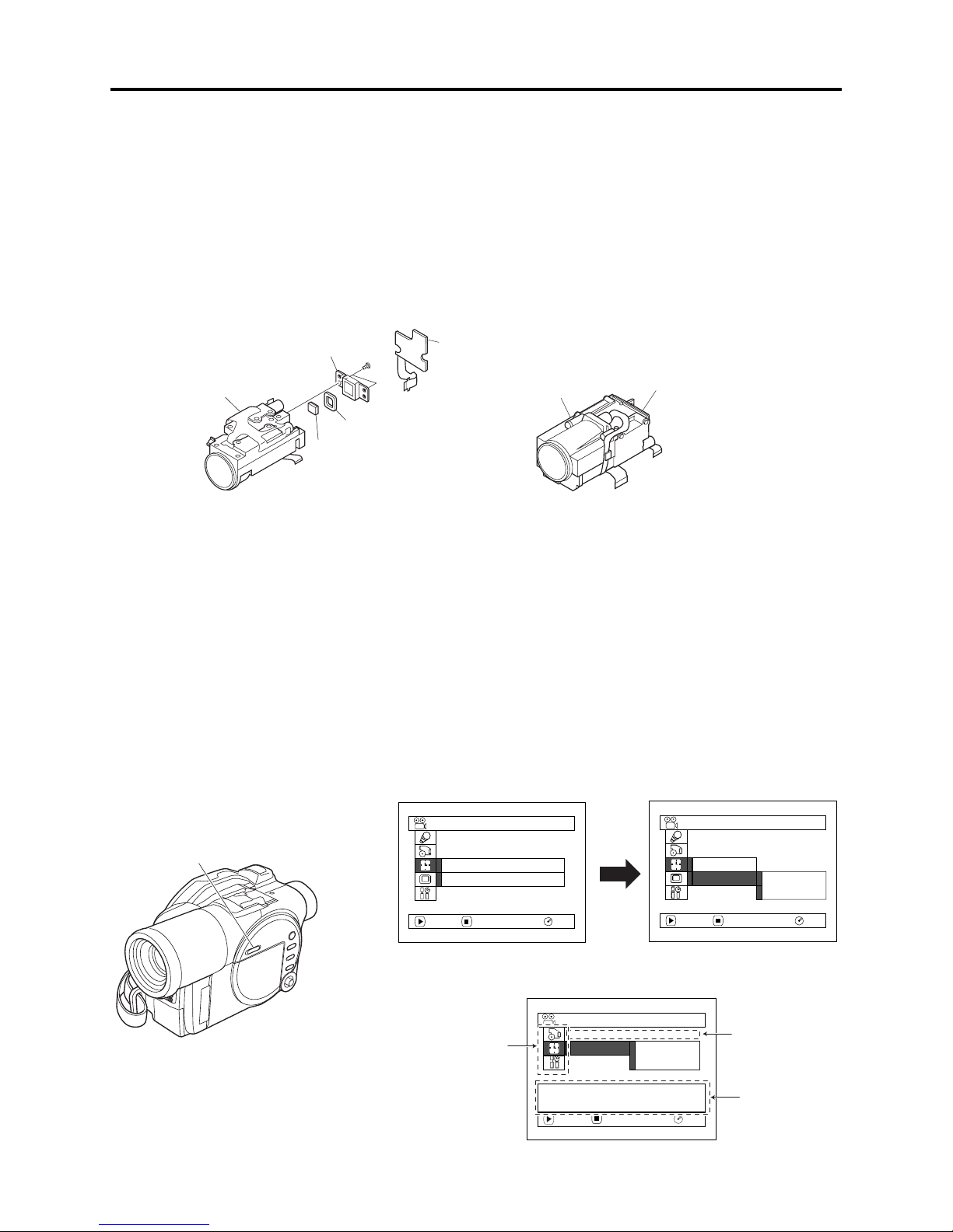
3-2 Description of Newly Adapted Technology
(1) QUICK MODE switch
The QUICK MODE switch changes over the screen for various settings and for Disc Navigation
between Quick mode and Normal mode.
The Quick mode displays only the fundamental menu items and the brief explanation on the
selected item/function is displayed across the bottom of screen.
Fig. 3-2-1 shows the position of QUICK MODE switch and an example of display screens.
Date/time setting screen in Normal mode:
QUICK MODE switch
2-step operation until setting screen appears
Date Setup
:
Date Mode
Date Set
ENTER RETURN
M/D/Y
RAM
Date Setup
Date Mode
Date Set
ENTER RETURN
1 / 1 / 2004
12:00AM
RAM
Date/time setting screen in Quick mode:
1-step operation until setting screen appears
Date Setup
Camera function
setup and LCD
monitor setup
are omitted.
Date Set
Set the current date and
time.
ENTER RETURN
Fig. 3-2-1
3 - 2
1 / 1 / 2004
12:00AM
RAM
Display mode
setting is omitted.
Item/function
explanatory
display
4
Troubleshooting
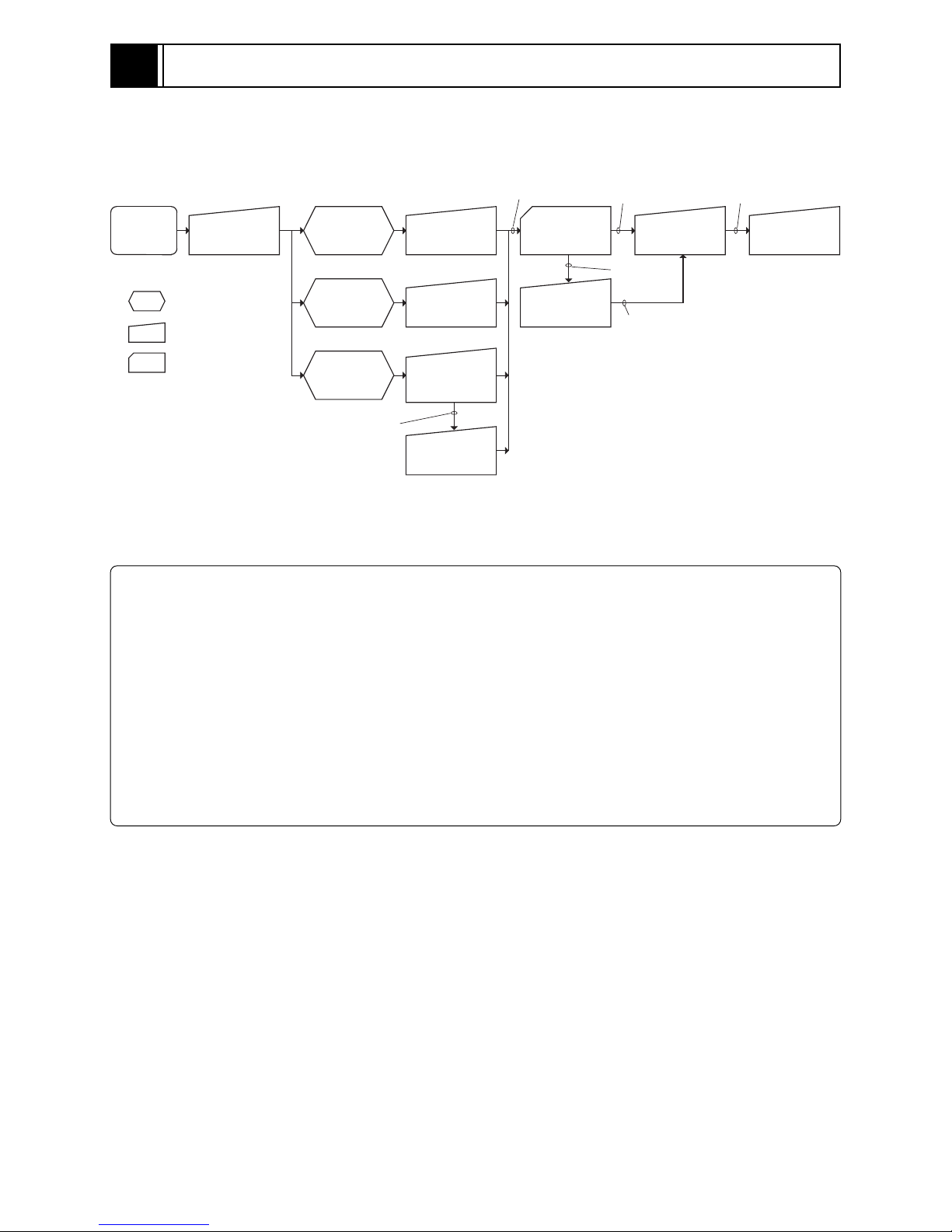
4-1 Procedure for Troubleshooting
Perform troubleshooting in the order shown in Fig. 4-1-1.
Updating
unneeded
Updating
needed
No improvement
after updating
Trouble
Diagnosis
(section 4-7)
No improvement
Check
phenomenon
System reset
(section 4-2)
: Phenomenon
: Troubleshooting
: Check
No message or
error code
*1
appears
Message
*1
appears
Error code
*1
appears
Error codes not included in
service manual appear
Problem guide
(section 4-3)
Messages and
Troubleshooting
(section 4-4)
Major Error
Codes and
Troubleshooting
(section 4-5-3)
Check
troubleshooting
with the factory
No improvement
Check firmware
version
(section 4-6-1)
Update firmware
(section 4-6-2)
*1: Messages and error codes will appear on LCD monitor or in viewfinder.
Fig. 4-1-1
Note:
1) Before troubleshooting or servicing, be sure to obtain customer approval for the following:
4.2.1 List of items to be reset
Check
troubleshooting
with the factory
a) The image data stored on disc may be lost depending on the details and situation of fault
(defect).
b) The date/time and various settings, including video recording mode, designated by customer
after purchase may in some cases be reset to the defaults before purchase (factory settings).
2) Take note of settings on received product, referring to “4-2 System Resetting/Resetting Camera
Functions”: The notes will be necessary not only for resetting, but for checking defects that occur
under the particular setting conditions.
4 - 1

Troubleshooting > System Resetting/Resetting Camera Functions
4-2 System Resetting/Resetting Camera Functions
The DZ-MV580A/MV550A has two types of reset function: “System reset” and “Resetting camera
functions”.
The reset operation will return the various settings to the defaults when the DZ-MV580A/MV550A
was shipped form factory.
Information:
If a defect occurs in product, take note of settings, and then execute system reset first: The defect
may disappear.
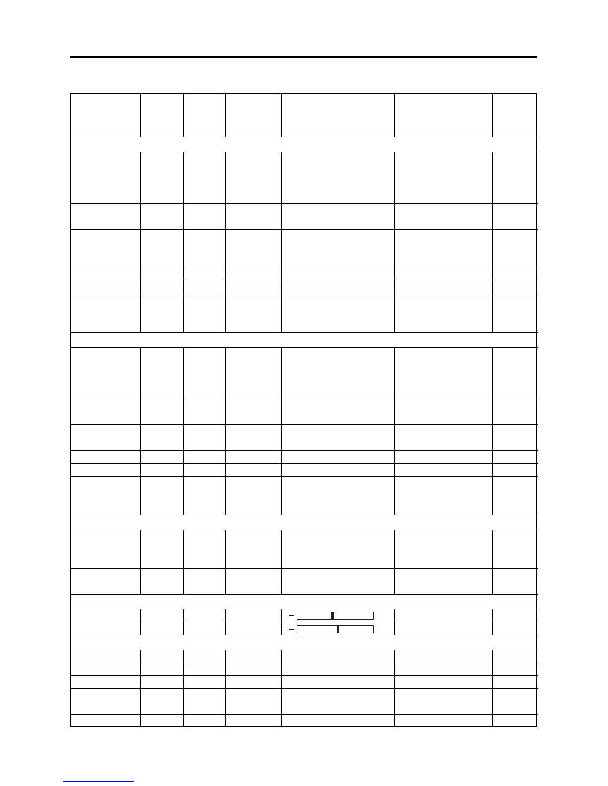
4-2-1 List of items to be reset
Table 4-2-1 shows the items that will be reset to defaults at the factory by the two types of reset
operation: “system reset” and “resetting camera functions”.
Use the memo column provided in the table to enter the settings of any received device.
(1) Procedure for checking settings
1) Use a battery or the AC adapter/charger to power the DZ-MV580A/MV550A.
2) Set the QUICK MODE switch to “OFF”.
3) Insert a DVD-RAM disc, and then set the power switch to “VIDEO”. For subsequent steps,
operate the DZ-MV580A/MV550A while viewing the LCD monitor or viewfinder.
4) Press the MENU button to display the camera function setup menu screen: Make sure of the
settings.
5) Operate the joystick to display the menu screens for record function setup, date function setup,
LCD monitor setup and initial setup in sequence, making sure of the settings.
At this time, the items on photo quality, external photo input and self-timer will not appear, since
they are related to photo recording: Check them in steps 6) and 7).
6) Set the power switch to “[CARD]PHOTO”. It is not necessary to insert a card at this time.
7) Press the MENU button to display the camera function setup menu screen, and then operate the
joystick to display the record function setup menu screen in order to check the settings on photo
quality, external photo input and self-timer.
8) After checking is complete, press the MENU button to restore the ordinary screen.
4 - 2
Troubleshooting > System Resetting/Resetting Camera Functions
Table 4-2-1 List of items to be reset
Camera
Item
System
reset
function
reset
Default at
factory
Setting range
Camera Functions Setup
Program AE
White Bal.
EIS
Dig. Zoom
MIC Filter
16:9
Yes
Yes
Yes
Yes
Yes
Yes
Yes
Yes
Yes
Yes
Yes
Yes
Auto
Auto
On
40×
Off
Off
Auto, Sports, Portrait,
Spotlight, Sand & Snow,
Low Light
Auto, Set, Outdoor,
Indoor1, Indoor2
On, Off
240×, 40×, Off
On, Off
On, Off (The DZ-MV550A
does not have the 16:9
setting)
Record Functions Setup
VIDEO Mode
Quality
Input Source
PHOTO Input
Self Timer
OSD Output
Yes
Yes
Yes
Yes
Yes
Yes
Yes
Yes
Yes
Yes
Yes
Yes
FINE
FINE
CAMERA
Field
Off
On
With DVD-RAM disc:
XTRA, FINE, STD
With DVD-R disc:
FINE, STD
FINE, NORM, ECO
CAMERA, LINE, S LINE
Frame, Field
On, Off
On, Off
Date Setup
Date Mode
Date Set
Yes
Yes
Yes
No
M/D/Y
1/1/2004
12:00AM
PM5:00 Y/M/D,
5:00PM M/D/Y,
17:00 D/M/Y
-----------------
LCD Setup
Brightness
Color Level
Yes
Yes
Yes
Yes
Center
Center
Initial Setup
Beep
Power Save
Record LED
Language
Demo Mode
Yes
Yes
Yes
Yes
Yes
Yes
Yes
Yes
Yes
Yes
On
Off
On
English
Auto
On, Off
On, Off
On, Off
English, French,
Spanish, German, Italian
Auto, Off, Start
Yes: Will be reset
No: Will not be reset
Remarks
Low Light will not
appear when “VIDEO
mode: STD” is
specified.
Displayed on DZMV580A only in the
Video mode
Displayed only in the
Video mode
Displayed only in the
Video mode
Displayed only in the
card photo mode
S LINE is displayed
only on DZ-MV580A
Displayed only when
“Input Source:
CAMERA” is specified
+
+
Memo
4 - 3

Troubleshooting > System Resetting/Resetting Camera Functions
4-2-2 System reset procedure
1) Set the power switch to “POWER OFF”, and
then disconnect the battery or AC adapter/
charger.
2) Use a fine tipped pen, etc. to hold down the
RESET button for approx. 2 seconds.
Fig. 4-2-1
RESET
4-2-3 Procedure for resetting camera functions
1) Connect the battery or AC adapter/charger to power the DZ-MV580A/MV550A.
2) Set the power switch to “VIDEO” and place the DZ-MV580A/MV550A in the recording pause
status; loading disc is not necessary at this time. For the following steps, operate DZ-MV580A/
MV550A while viewing the LCD monitor or viewfinder.
3) Set the quick mode switch to “OFF”.
4) Press the MENU button to display the camera setting menu screen.
5) Use the joystick to choose “Initial Setup”, and then press the center of joystick.
6) Use the joystick to choose “Reset”, and then press the center of joystick: The screen for verifying
reset will appear.
7) Use the joystick to choose “YES”, and then press the center of joystick: Reset will be executed.
8) After reset, press the MENU button to close the camera setting menu.
4 - 4
Troubleshooting > Problem Guide
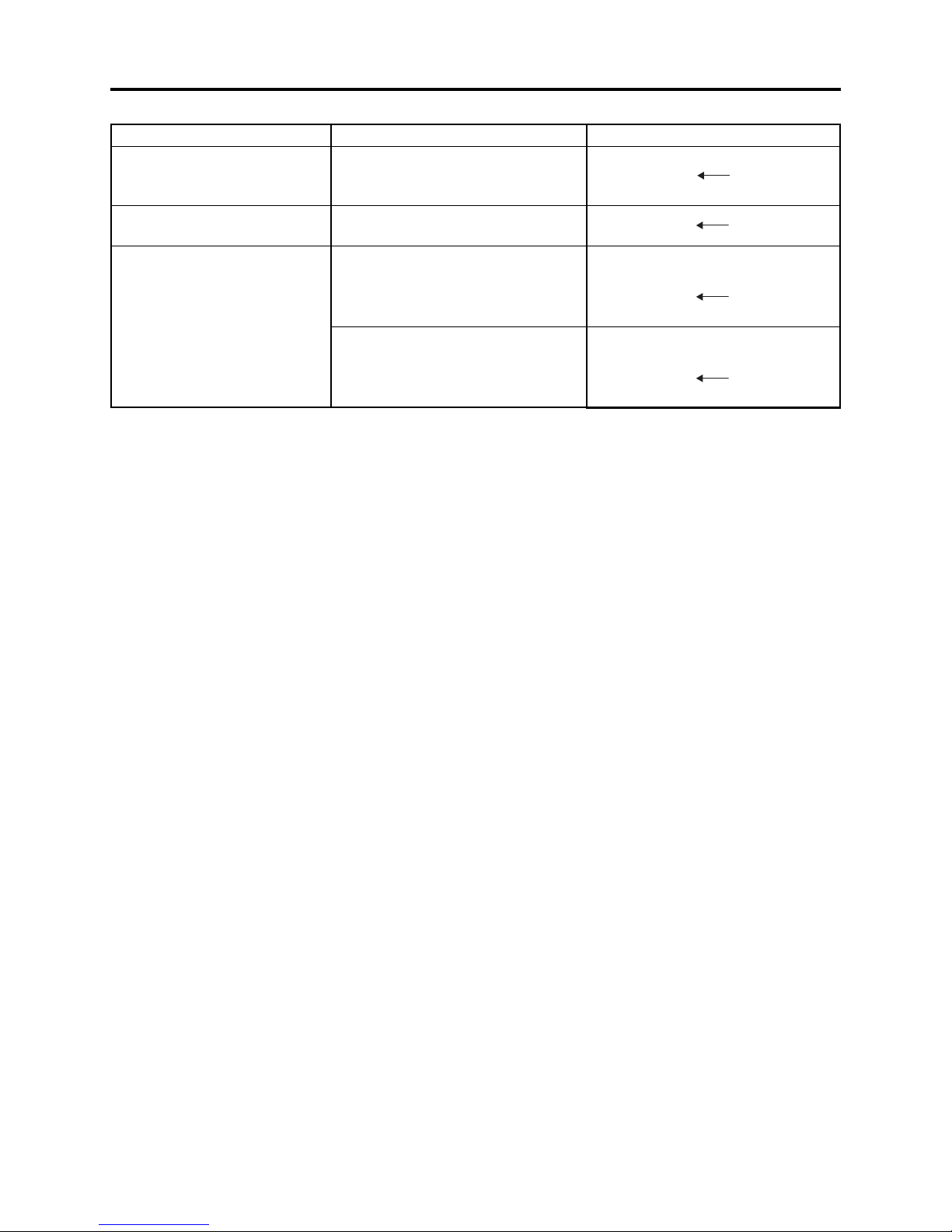
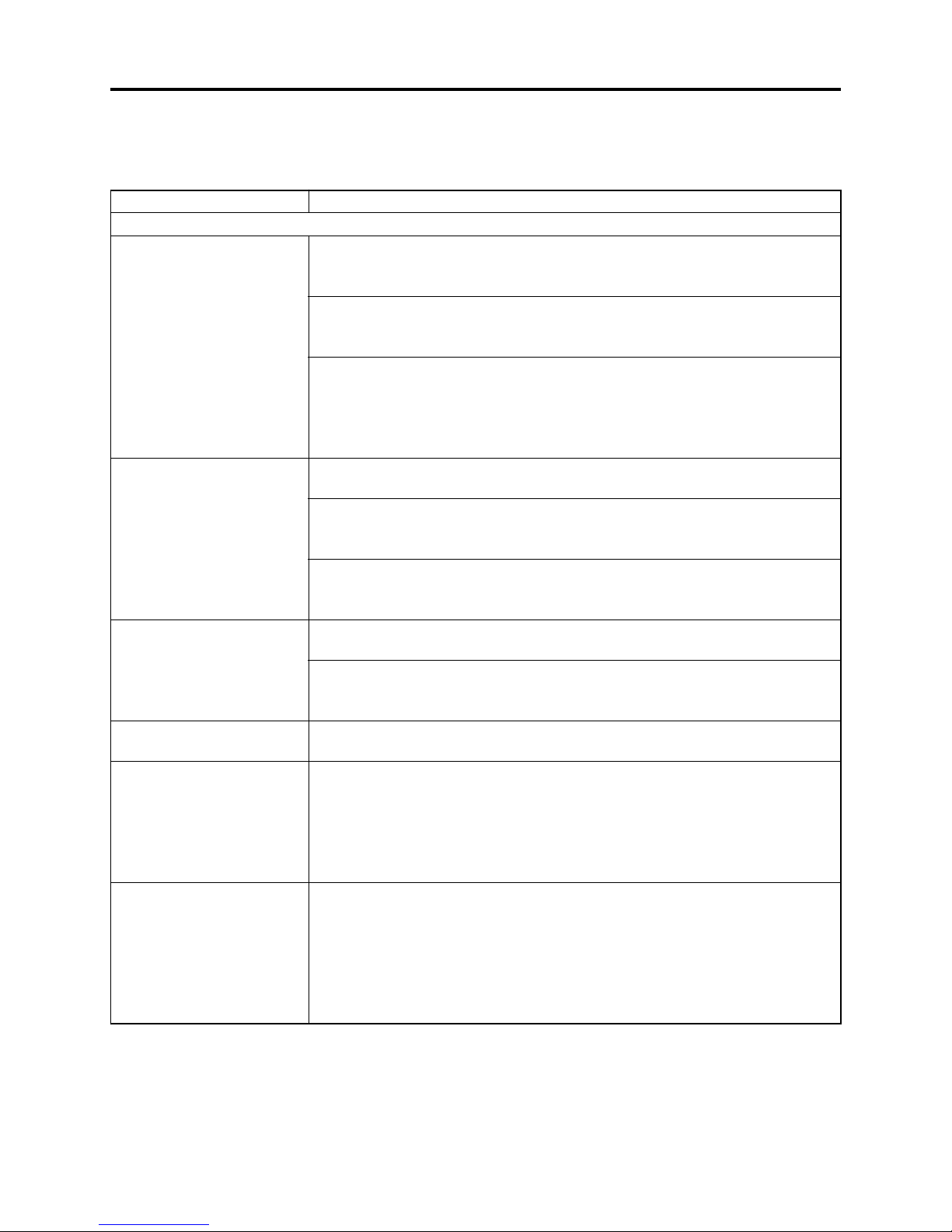
4-3 Problem Guide
Check the following before judging that DZ-MV580A/MV550A is faulty.
Symptom
Battery cannot be charged.
Battery weakens fast.
The CHARGE indicator on
AC adapter/charger is
blinking.
Power turns off immediately
after being turned on.
Power goes off unexpectedly.
Power cannot be turned off.
Cause and Correction
Power supplies
Is the DC power cord connected to AC adapter/charger?
Unplug it. If the DC power cord is connected, the AC adapter/charger will not
enter the charge status.
Is the battery abnormally hot?
Remove the battery from AC adapter/charger, leave it as is until it cools down,
and then charge it again.
Has the battery been unused for a long time?
Remove the battery from AC adapter/charger, and then reattach it. If the
battery is still not charged, it may be dead: Purchase a new one.
**
* If the battery does not charge after you try the above four procedures, it may
**
be dead: Purchase a new battery.
Is the ambient temperature is too low or high?
Always charge the battery at 50 - 86°F (10 - 30°C.)
Are you using the DZ-MV580A/MV550A where the temperature is low?
A fully charged battery may be discharged sooner than usual at low
temperatures. Keep extra batteries on hand.
Battery may be dead: Replace with a new one.
The performance of battery will deteriorate if it is used for an extended period of
time or frequently.
Is the ambient temperature is too low or high?
Always charge the battery at 50 - 86°F (10 - 30°C.)
The battery may be over-discharged.
Continue charging: The CHARGE indicator will change to a steady light, and
the battery will be charged normally.
Is battery charged?
Charge it.
Is Power Save specified "On"?
The specifications state that the powered DZ-MV580A/MV550A automatically
turns off if it is left for as long as 5 minutes without performing recording or
playback, with "Power Save: On" specified. Set the power switch to "POWER
OFF", and then turn DZ-MV580A/MV550A on again. To stop automatic power
off, specify "Power Save: Off".
Execute system reset (disconnect the battery or AC adapter/charger, and then
use a fine tipped pen, etc. to hold down the RESET button for several seconds).
Then connect a battery or AC adapter/charger and make sure the DZ-MV580A/
MV550A accepts operation.
System reset will return the date/time and all items set using menu (except for
LCD settings) to the defaults at the factory. After recovery, reset the date/time
and each setting item as required.
4 - 5
Troubleshooting > Problem Guide
Symptom Cause and Correction
Pressing the REC button
will not start recording.
Recording starts but stops
immediately.
Power switch does not
change to PHOTO (disc).
LCD screen is hard to see.
Black dots or red, blue or
green dots always lit appear
on LCD screen or in
Viewfinder.
Focus is not correct.
Is input image copy-guarded?
The specifications state that DZ-MV580A/MV550A cannot record a copy-guarded
image.
Does dirt or fingerprint adhere to
disc, or is disc scratched?
Clean the disc. If there is still no
improvement, replace the disc.
Is some other AV device directly connected to the AV input/output jack of DZMV580A/MV550A?
If the AV device is connected via several other devices, such as AV selector, the
video signal may not be transmitted correctly. In such a case, reduce the number
of devices through which the video signal is transmitted, or connect AV device
directly.
Are you attempting to record image from video game or PC?
Depending on video game or PC, image cannot be recorded on DZ-MV580A/
MV550A.
Is the LOCK switch beside the power switch set to the left? Switch it to the right
to release the lock.
Has brightness of LCD screen been adjusted?
Stop recording and adjust the brightness.
Is DZ-MV580A/MV550A being used outdoors?
Use the viewfinder. When using LCD monitor, adjust angle so that LCD screen
is not exposed to direct sunlight.
The panels used for LCD monitor and viewfinder of DZ-MV580A/MV550A are
produced using highly precise technology. However, 0.01% or less of total pixels
may not light (black dots) or may remain lit (red, blue, green dots). (The effective
amount of pixels on LCD panel is 99.99% or more.) This shows the limitations of
the current technology, and does not indicate a fault that will interfere with the
operation of LCD panel or operation of DZ-MV580A/MV550A.
Is it difficult to use auto-focus with the subject?
Focus manually.
Does "MF" appear?
The DZ-MV580A/MV550A is set to manual focus. Focus the subject manually, or
release manual focus.
Is the diopter control of viewfinder correctly adjusted?
Adjust the diopter control.
In cases other than the above, set the power switch to "POWER OFF", and then
reset it to a position other then “POWER OFF”.
During recording
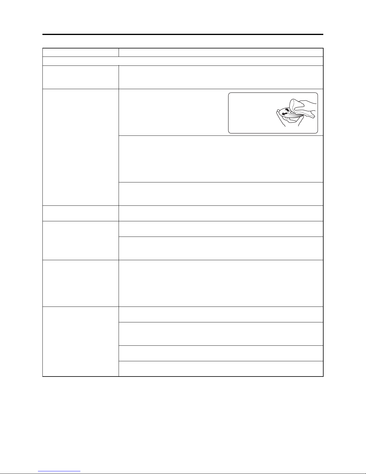
Disc cleaning method:
Use soft cloth to clean
from inner to outer
circumference in
axial direction.
[Never use solvent.]
4 - 6
Troubleshooting > Problem Guide
Symptom Cause and Correction
Recognition of disc is not
complete.
Pressing the playback
button will not start
playback.
No playback image appears
on TV screen.
Playback picture is
momentarily interrupted.
Poor playback picture.
Playback picture is greatly
distorted.
No sound.
Disc Navigation thumbnails
do not appear.
Photos on card cannot be
played back.
It will take some time to
play back photos on card.
Does dirt or fingerprint adhere to disc, or is disc scratched?
Clean the disc.
Was the image recorded on a device other than DZ-MV580A/MV550A?
Playback of image recorded on devices other than DZ-MV580A/MV550A may be
impossible.
Has scene been edited on a device other than DZ-MV580A/MV550A?
If a scene that was recorded on DZ-MV580A/MV550A is edited on a device other
than DZ-MV580A/MV550A, playback may not be possible on DZ-MV580A/
MV550A.
Is TV input selector set correctly?
If the TV has multiple video input jacks, check to see whether the correct input
jack was selected.
If DZ-MV580A/MV550A is connected to VCR, set the input selector of VCR to
"external input (LINE)".
Is DZ-MV580A/MV550A connected to TV correctly?
Check the connections.
Does dirt or fingerprint adhere to disc, or is disc scratched?
Clean the disc.
Was the image input from analog VCR (VHS, 8 mm) and recorded?
The problem may be improved if a VCR equipped with TBC (time base corrector)
circuit is used for playback.
Was recording of external input made with "Frame" specified?
Specify "Field" for "PHOTO Input" in record mode settings.
Is the TV volume control set correctly?
Adjust volume control on TV.
Did the image recorded from AV input/output jack have noise or disturbance?
Re-record image with no noise or disturbance.
Is a photo recorded on devices other than DZ-MV580A/MV550A being played
back?
The DZ-MV580A/MV550A specifications allow it to play back photos that are
recorded conforming to DCF standard and have 80-4000 horizontal pixels x 603000 vertical pixels.
Make sure that the photo to be played back satisfies these specifications. Note
that even photos that satisfy the specifications may not be playable, depending
on the recording status.
The thumbnail of any photo that cannot be played back will appear in single
blue.
Is a photo with a large number of pixels being played back?
It will take some time to play back a photo with a large number of pixels.
During playback
4 - 7
 Loading...