

Hitachi DZMV100A Service Manual
SERVICE MANUAL
TK No. 7006E
DZ-MV100A
SPECIFICATIONS AND PARTS ARE SUBJECT TO CHANGE FOR IMPROVEMENT
DVD VIDEO CAMERA/RECORDER
2000December Digital Media Products Division,Tokai
PRODUCT SAFETY NOTICE
Many electrical and mechanical parts have special safety-related characteristics. These are often not evident from visual
inspection nor can the protection afforded by them necessarily be obtained by using replacement components rated for a
higher voltage, wattage, etc. Replacement parts which have these special safety characteristics are identified in this
Service Manual. Electrical components having such features are identified by marking with a on the schematics and the
!
parts list in this Service Manual. The use of a substitute replacement component which does not have the same safety
characteristics as the HITACHI recommended replacement one, shown in the parts list in this Service Manual, may create
shock, fire, or other hazards. Product safety is continuously under review and new instructions are issued from time to time.
For the latest information, always consult the current HITACHI Service Manual. A subscription to, or additional copies for,
HITACHI Service Manual may be obtained at a nominal charge from HITACHI SALES CORPORATION.
CAUTION (COLOR LCD)
LCD display; the liquid crystal display (LCD) panel is mode by highly precise technology.
More than 99.99% of its picture elements (pixels) are effective, but some (less than 0.01%) may appear as colored
bright dots. This mode not indicate a fault as the LCD panel stretches the limits of current technology.
CLASS 1
LASER PROCTECT
CAUTION
VISI
BLE
LASER
NOT
DO
AND
INVI
RADIATION
STARE
SI
INTO
BLE
WHEN
BEAM.
OPEN.
CAUTION
This product contains a laser diode of
higher class than 1. To ensure continued safety, do not remove any covers
or attempt to gain access to the inside of the product. Refer all servicing
to qualified personnel.
Contents included:
ANA and DIG circuit board diagrams included are for reference during troubleshooting.
This manual does not include the schematic diagrams of ANA and DIG circuit boards, since these boards must be
replaced in units of board and their components are not assigned as service parts.
SHD, RAM2LD and PHD circuit board diagrams included are for reference during troubleshooting.
This manual does not include the schematic diagrams of SHD, RAM2LD and PHD circuit boards, since these
boards are included in the mechanism unit and they or their components are not assigned as service parts.
Microsoft, MS, MS-DOS, Windows and Windows NT are registered trademarks of Microsoft Corporation.
Pentium and Celeron are registered trademarks of Intel Corporation.
Manufactured under license from Dolby Laboratories.
"Dolby" and double-D symbol are trademarks of Dolby Laboratories.
Confidential unpublished works. (C) 1992-2000 Dolby Laboratories Inc. All rights reserved.
IBM is registered trademarks of International Business Machines Corporations.
Other company names and product names listed are trademarks or brand names belonging to each company.
CAUTION-1
Notes When Using Service Manual
The following shows the contents to be noted when using service manual:
1. Value units used in parts list
Certain symbols are indicated below for value units of
resistors, capacitors and coils in parts list. When you read
them note the following regular indications:
Parts
Resistor
Capacitor
Coil
Indication in list Regular indication
...........................................
KOHM
................................................
UF
................................................
PF
................................................
UH
...............................................
MH
2. Values in schematic diagrams
The values, dielectric strength (power capacitance) and
tolerances of the resistors (excluding variable resistors)
and capacitors are indicated in the schematic diagrams
using abbreviations.
[Resistors]
Item
Value
Tolerance
Power
capacitance
Indication
No indication
...................................................
K
..................................................
M
No indication
(All tolerances other than ±5% are
indicated in schematic diagrams)
No indication
(1/16W for leadless resistors without
indication)
All capacitances other than the above
are indicated in schematic diagrams.
...................................
.............................
............................
±5%
1/8W
k
M
k
µF
pF
µH
mH
3. Identifications of sides A/B in
circuit board diagrams
1) Board having a pattern on one side and parts on both
sides.
Side A: Shows discrete parts, viewed from the pattern
side.
Side B: Shows leadless parts, viewed from the
pattern side.
2) Board having patterns on both sides and parts on
both sides.
Side A: Shows parts and patterns which can be seen
when the case is opened.
Side B: Shows parts and the pattern on the back of
side A.
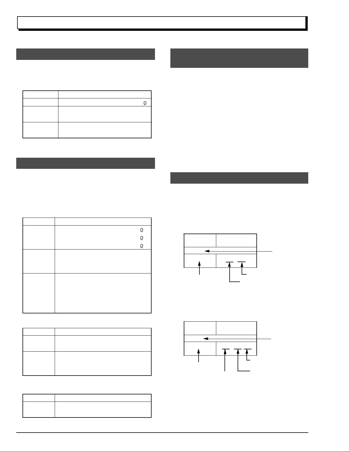
4. Table for indexing locations of parts
This table shows locations of each part on circuit board
diagrams. The locations are indicated using the guide
scales on the external lines of diagrams.
1) One diagram indicated for each board
Symbol
No.
IC
IC1201
Circuit No.
2) Two diagrams indicated for each board
Parts
Location
Type of part
2 A
Zone "A" on board diagram
Zone "2" on board diagram
[Capacitors]
Item
Value
Dielectric
strength
[Coils]
Item
Value
CAUTION-2
Indication
No indication
...................................................
P
No indication
(All dielectric strengths other than 50V
are indicated in schematic diagrams)
Indication
....................................................
µ
..................................................
m
.................................
..............................
µF
pF
50V
µH
mH
Symbol
No.
IC
IC1201
Circuit No.
Parts
Location
A - 2 A
A: Shows side A
B: Shows side B
Type of
part
Zone "A" on board
diagram
Zone "2" on board
diagram

CONTENTS
CHAPTER 1 GENERAL INFORMATION
1. Specifications
2. Information on DVD-RAM Discs
2.1 Comparison of DVD-RAM Discs
2.2 DVD Video Recording Standard
2.3 Comparison between
DVD-RAM and DVD-RW/R
2.4 Available DVD-RAM Discs
2.5 Initializing (formatting) DVD-RAM Discs
2.6 Handling DVD-RAM Disc
2.7 Removing DVD-RAM Disc from Cartridge
3. Subsidiary Functions for Servicing
3.1 Forced disc formatting
3.2 Still (JPEG) file operation
3.3 Firmware version display
3.4 Error code display
3.5 Playback file detailed information display
3.6 Deleting information control (RX) file
4. Explanation of Trouble Messages
5. Troubleshooting Guide of DVD Video
Camera/recorder
6. Updating Firmware
6.1 Firmware programs
6.2 How to update
7. Service Manual Abbreviation List
8. Fro the Battery
9. Extract from the Instruction Manual
Cleaning
Names of Parts
System Reset
Setting Up the Battery
Setting Date and Time
Initializing DVD-RAM Disc
Trouble Message
......................................................
.........................
..................
.................
..........................
...........................
......
.............................
.....................
..................................
.............................
.............................
........................................
....
...........
......................
.................................................
..............................................
......................................
..............................................
.......................
....................................................
....................
.......................................................
............................................
...............................................
..................................
.................................
............................
.........................................
...
E1-1
E1-2
E1-2
E1-2
E1-3
E1-3
E1-4
E1-4
E1-4
E1-6
E1-6
E1-6
E1-7
E1-7
E1-8
E1-8
E1-9
E1-13
E1-16
E1-16
E1-16
E1-17
E1-19
E1-20
E1-20
E1-20
E1-22
E1-23
E1-24
E1-25
E1-26
CHAPTER 2 DISASSEMBLY
1. Parts Location
2. Before Starting Disassembly
3. Disassembly Procedure
3.1 Top Cover, R-Block, L-Block
3.2 LCD-U Case, LCD Block, Front Block,
RUB Sheet
3.3 Jack Cover, Flash Unit, JKR Circuit Board,
JKF Circuit Board, Microphone, IR Filter,
Lens Hood, Front Case
3.4 EVF Block, Rear Cover, Power Terminal
3.5 ANA Circuit Board, Camera Block, DIG
Circuit Board, LSP Shield, Side Case-L
3.6 Disc Cover, Switch Unit
3.7 Link Bracket R, Link Bracket L, Loader,
Mechanism Unit
3.8 Lock Unit, Side Case-R
3.9 GYR Circuit Board, SEN Circuit Board,
Sensor, Lens
.....................................................
..............................
......................................
........................
...................................................
................................
.....
.......
................................
...........................................
................................
................................................
E2-1
E2-3
E2-5
E2-5
E2-6
E2-8
E2-9
E2-10
E2-10
E2-12
E2-14
E2-14
3.10 Eye Control, EVF-F Case, Plate-F,
EVF-B Case, EVF LCD, EVF Backlight,
EBL Circuit Board
3.11 B/W LCD, LCD Power Unit, LCD Frame,
Backlight, Color LCD, LCD-B Case
4. Disassembly When Trouble Has Occurred
4.1 Cleaning EVF Screen
(Removing Eye Control)
4.2 Removing DVD-RAM Disc
5. Information on Installation Position of
Shields, etc.
5.1 Side Case-L
5.2 DIG Circuit Board
5.3 ANA Circuit Board
5.4 Power Terminal
5.5 Front Block
5.6 Mechanism Unit
5.7 Miscellaneous
........................................................
.........................................
.............
...............................
...........................
.................................................
.........................................
........................................
............................................
...................................................
...........................................
..............................................
CHAPTER 3 ELECTRIC CIRCUIT
ADJUSTMENT
1. Test Equipment/Jigs Necessary for
Adjustment
1.1 List of equipment and jigs
1.2 List of charts for adjustment
1.3 Test equipment, etc.
2. Before Starting Adjustment
2.1 Connection for adjustment
2.2 Notes
2.3 Setting video camera/recorder
2.4 Setting test equipment
3. List of Adjustment Item
4. Starting Adjustment Program (MAP: Manual
Adjustment Program)
5. Adjustment Procedure
5.1 Data Initialize
(1) Data Initialize
5.2 Adjustment
(1) Sampling Pulse Adjustment
(2) Auto Iris Control Adjustment
(3) Shutter Adjustment
(4) White Balance Adjustment
(5) Chroma Gain Adjustment
5.3 Autofocus
(1) Zoom Trace Adjustment
(2) AF Noise Level Adjustment
5.4 Stabilizer
(1) Stabilizer Adjustment
5.5 Spot Noise
(1) Spot Noise Adjustment
6. Error Message
6.1 Error Message of Adjustment
6.2 Error Message of Autofocus
6.3 Error Message of Stabilize
6.4 Error Message of Spot Noise
.........................................................
............................
.........................
.....................................
.................................
...........................
............................................................
.....................
.................................
......................................
..........................................
........................................
................................................
................................................
...................................................
.........................
........................
.......................................
...........................
.............................
.....................................................
...............................
..........................
......................................................
...................................
....................................................
.................................
....................................................
.......................
........................
...........................
.......................
.........
E2-16
E2-17
E2-18
E2-18
E2-18
E2-21
E2-21
E2-21
E2-22
E2-22
E2-22
E2-23
E2-24
E3-1
E3-1
E3-1
E3-1
E3-2
E3-2
E3-2
E3-2
E3-3
E3-4
E3-5
E3-6
E3-6
E3-6
E3-6
E3-7
E3-7
E3-8
E3-10
E3-10
E3-12
E3-12
E3-12
E3-13
E3-13
E3-13
E3-13
E3-15
E3-15
E3-16
E3-16
E3-16
CONTENTS-1

CHAPTER 4 EXPLODED VIEW
CABINET-1
CABINET-2
ELECTRONIC VIEWFINDER (EVF)
LCD
CAMERA
ACCESSORIES
...............................................................
...............................................................
.........................
...........................................................................
..................................................................
........................................................
CHAPTER 5 REPLACEMENT
PARTS LIST
1. MECHANICAL PARTS LIST
2. ELECTRICAL PARTS LIST
...............................
................................
4-1
4-2
4-3
4-3
4-4
4-4
5-1
5-2
CHAPTER 6
SCHEMATIC, CIRCUIT BOARD
AND BLOCK DIAGRAMS
SCHEMATIC DIAGRAMS
INTERNAL WIRING DIAGRAM
SENSOR [SEN]
GYRO [GYR]
EVF BACK LIGHT [EBL]
JACK-F [JKF]
JACK-R [JKR]
CIRCUIT BOARD DIAGRAMS
.......................................................................
SEN
.......................................................................
GYR
........................................................................
EBL
ANA [SIDE-A] (*1)
ANA [SIDE-B] (*1)
DIG [SIDE-A] (*1)
DIG [SIDE-B] (*1)
........................................................................
JKF
........................................................................
JKR
SHD (*2)
RAM2LD (*2)
PHD (*2)
.....................................................
.........................................................
........................................................
........................................................
.................................................
.................................................
..................................................
..................................................
................................................................
.........................................................
................................................................
............................
.......................................
6-1
6-3
6-4
6-5
6-6
6-7
6-9
6-9
6-10
6-11
6-13
6-15
6-17
6-19
6-19
6-20
6-20
6-21
BLOCK DIAGRAMS
AV PROCESS SECTION
8cm DVD-RAM DRIVE SECTION
*1: The circuit board diagrams included are for reference
during troubleshooting.
This manual does not include the schematic diagrams
of ANA and DIG circuit boards, since these boards
must be replaced in units of board and their
components are not assigned as service parts.
*2: The circuit board diagrams included are for reference
during troubleshooting.
This manual does not include the schematic diagrams
of SHD, RAM2LD and PHD circuit boards, since these
boards are included in the mechanism unit and they or
their components are not assigned as service parts.
......................................
.........................
CONTENTS-2
6-23
6-24

CHAPTER 1 GENERAL INFORMATION
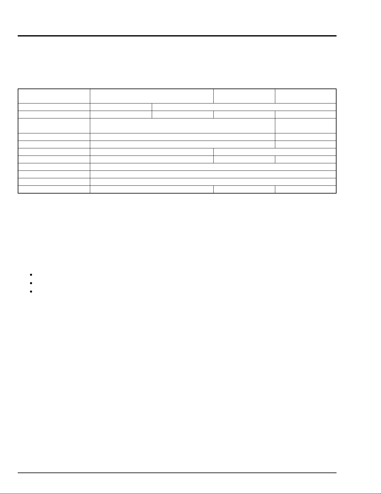
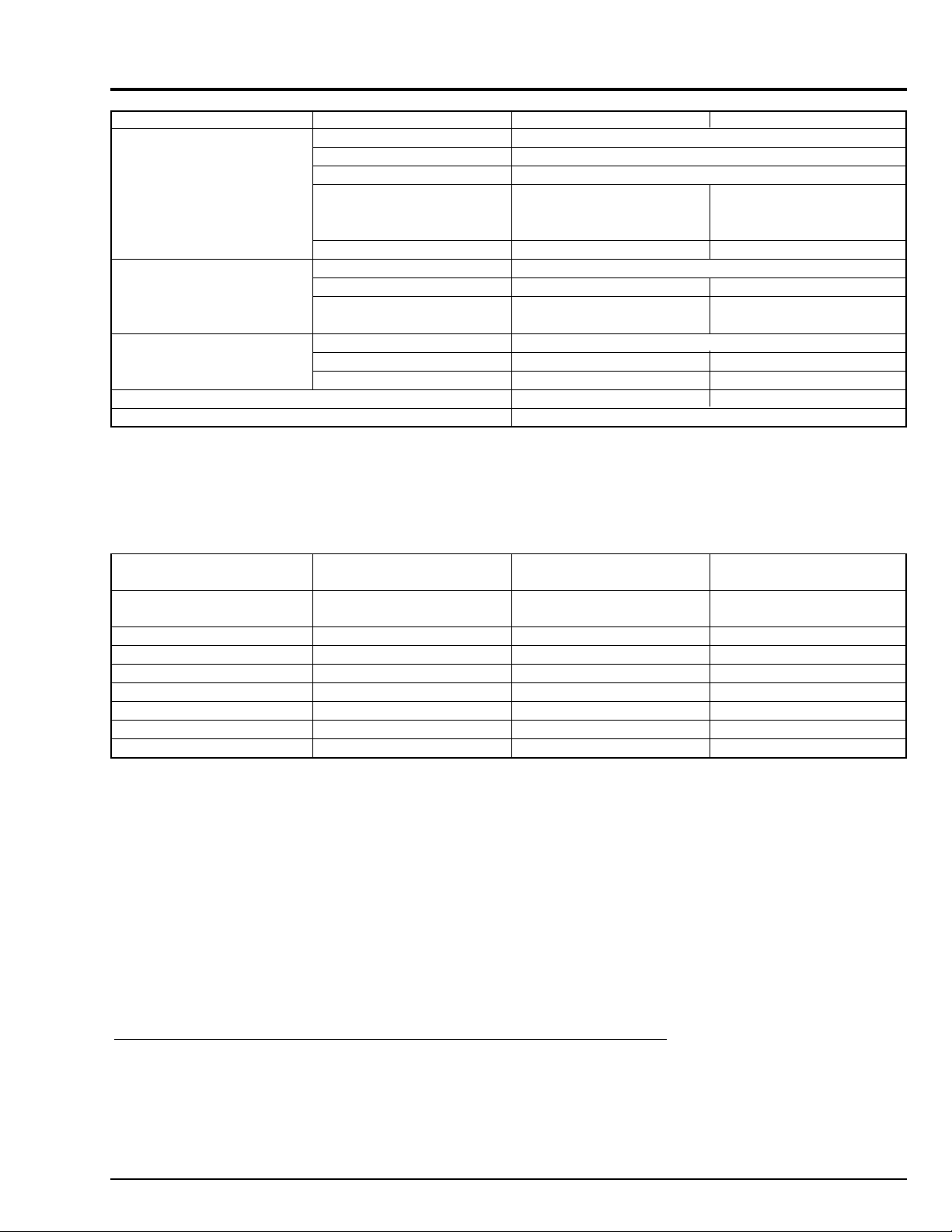
1. Specification
Power requirements 7.2 V DC
CCD (number of effective pixels) 1/4-inch interlaced, total number of pixels: approx.
1,000,000 (movie: approx. 720,000: still: approx.
1,000,000)
Lens F2.0 - 2.7, f = 3/16" - 1-15/16" (4.1 - 49.2 mm)
Filter diameter: 1-7/16" (37 mm)
Focal length (converted to 35 mm camera) Movie: approx. 1-3/4" - 20-13/16" (44 - 528 mm)
Still: approx. 1-1/2" - 17-15/16" (38 - 456 mm)
Focus Auto/Manual
Zoom Optical 12 ×, 48 × with digital zoom added
Required minimum illumination 8 lx
Viewfinder 0.44-inch color TFT (approx. 180,000 pixels)
LCD monitor 3.5-inch color TFT (approx. 200,000 pixels)
Electronic image stabilizer Electronic type
Shutter speed 1/60 - 1/4000 second (movie)
Flash (AUTO/ON/OFF) Still recording only
Self-timer recording Still recording only
External microphone jack 3.5 mm Ø stereo minijack: Recommended microphone
impedance 600 ohm - 1 k ohm
Recording mode Movie (with sound)
Still
Maximum recordable time Movie: approx. 60 minutes (FINE)*
(on both sides of disc) approx. 120 minutes (STND)*
Maximum number of recordable stills 1998*
(on both sides of disc)
Recording format Movie: Conforming to DVD video recording standard
(MPEG audio)
Still: Simultaneous recording, conforming to DVD video
recording standard and JPEG (1,280 × 960
pixels)
Audio playback format MPEG, Dolby AC3
Recording medium 8 cm DVD-RAM disc (conforming to DVD-RAM Book 2.1)
Jacks Video/Audio input/output × 1, S-video input/output × 1,
External microphone input × 1, Digital input/output
terminal (connected to PC USB jack) × 1
Battery system Lithium-ion
Power consumption approx. 6.5 W when recording with LCD monitor off
Dimensions approx. 3-1/16" × 4-1/4" × 6-9/16" (78 × 108 × 166 mm)
(W × H × D) (excluding hood and projections)
Operating temperature 32 - 104 °F (0 - 40 °C) (less than 80 %).
32 - 95 °F (0 - 35 °C) when connected to PC.
Storage temperature -4 - 140 °F (-20 - 60 °C)
Weight 1.83 lbs (approx. 830 g) (without battery or disc)
Total weight when recording 2.18 lbs (approx. 990 g) (when using BP16 battery)
Provided accessories AC adapter/charge, battery, DC power cable, AV input/
output cable, infrared remote control, 2 "AA" batteries for
remote control, lens cap string, shoulder strap, power
cable, 2 ferrite cores, DVD-RAM disc, PC connection
cable, PC connection software CD-ROM
* This number will decrease if stills and movies are recorded on the same disc.
AC Adapter/Charger DZ-ACP1
Power requirements 100 - 240 V AC, 50/60 Hz
Input capacity 40 VA (at 100 V)
DC output 8.0 V, 2.0 A
Charge output 8.4 V, 2.2 A
Weight approx. 0.61 lbs (approx. 280 g ) (AC adapter/charger)
External dimensions (W × H × D) approx. 2-9/16" × 1-15/16" × 4-1/8" (65 × 50 × 105 mm)
Ambient temperature 32 - 104 °F (0 - 40 °C)
Allowable relative humidity 20 - 85 %
E1 - 1
2. Information on DVD-RAM Discs
2.1 Comparison of DVD-RAM Discs
The 4.7GB DVD-RAM is standardized as Version 2.0 with respect to the 2.6GB DVD-RAM (Version 1.0), and the major
differences are as follows:
The 8-cm DVD-RAM media is standardized as Version 2.1: It can be used with disc removed from cartridge as well as in
cartridge in the same way as with 12-cm DVD-RAM Type 2.
4.7 GB (1.46 GB) DVD-RAM
(Version 2.1 & 2.0)
Diameter of media
Capacity (per side)
Laser wavelength (NA)
Recording format
Track format
Track pitch
Date recording bit length
Sector size
Modulation scheme
Error correction format
Recording rate
Notes: 1) In addition to the above, the 4.7GB DVD-RAM has a new defect control system to handle real time recording of
AV data.
2) Among the rewritable DVD standards, only the 4.7GB DVD-RAM is standardized for the 8cm size.
8 cm
1.46 GB
650 nm (0.6)
Mark edge recording
Wobble land groove
0.615 µm
0.28 µm
2048 bytes
8/16 modulation
RSPC (Reed Solomon Product Coding)
22.16 Mbps
12 cm
4.7 GB
2.6 GB DVD-RAM
(Version 1.0)
2.6 GB
0.74 µm
0.41 µm
11.08 Mbps
DVD-ROM
(reference)
4.7/8.5 GB
650 nm (0.6)
(playback only)
(Playback only)
Pit
0.27 µm
(Playback only)
2.2 DVD Video Recording Standard
The DVD video recording standard is a newly established common standard to record video on DVD in real time. The DVD
video standard has already been used for read-only DVD, but it was previously exclusively for playback, so the following
were difficult:
Recording in real time
Addition or deletion of video/audio
Editing
The DVD video standard was reviewed to establish a DVD video recording standard which defines the devices for achieving
the characteristics inherent in disc, starting with the following, in addition to the capabilities of real-time recording and editing
on rewritable DVD media:
E1 - 2
(As of March 2000)
Video
Audio
Sub-picture
Data for control (Navigation pack)
Multiplexing type
Coding format
Number of streams
Aspect ratio
Number of pixels (NTSC)
Still image data structure
Coding format
Number of streams
Number of channels per
stream
Coding format
Number of streams
Display control command
DVD Video Recording
MPEG1/MPEG2
1 stream only
4 : 3 / 16 : 9
720 × 480, 704 × 480,
544 × 480, 480 × 480,
352 × 480, 352 × 240
I picture of one still
MPEG/Dolby AC3/Linear PCM
Up to 2
Mono/Stereo/Dual Mono/Multi
(up to 71 channels)
Run-length encoding
1 only
Sub-set of that at right
None
MPEG2 program stream
2.3 Comparison between DVD-RAM and DVD-RW/R
In addition to DVD-RAM in rewritable DVDs, DVD-RW and DVD-R are also available.
The following table shows the differences in major specifications (Note 1) between these discs:
DVD Video (reference)
720 × 480, 704 × 480,
352 × 480, 352 × 240
Not defined
Up to 8
Mono/Stereo /Multi (up to 71
channels)
Up to 32
Full set
Provided (essential)
(As of April 2000,
investigated by Hitachi)
Capacity
(per side/both sides)
Laser wavelength (NA)
Write rate
Rewritable use
Cartridge
Video recording standard
8-cm standard
Major applications
Note 1: The differences between media are shown: The drives of Hitachi and other companies and applied products also
have individual specifications.
Note 2: There are two types of DVD-RAM: Disc used only while it is in cartridge (Type 1) and disc can be removed from
cartridge (Type2).
DVD-RAM (4.7GB)
4.7 GB/9.4 GB
650 nm (0.6)
2X
at least 100,000 times
Provided (Note 2)
Conforming
Provided
For PC/AV
DVD-RW (4.7GB)
4.7 GB/-----
635 nm/650 nm (0.6)
1X
at least 1,000 times
None
Conforming
None
For AV
DVD-R (4.7GB)
4.7 GB/-----
635 nm (0.6)
1X
only once
None
Non-conforming
Provided
For authoring software
2.4 Available DVD- RAM Discs
There are two types of DVD-RAM disc: for video camera and for PCs. Be sure to use 8 cm DVD-RAM discs (1.4 GB on one
side, 2.8 GB on both sides) noted for video camera use (for AV) with this DVD video camera/recorder.
Most discs for video camera use (for AV) can be removed from their cartridges for recording. Some discs for PC, however,
cannot be removed from their cartridges, and some can be removed but recording cannot be made on them. For details, read
the instruction sheet provided with discs or consult the disc maker.
Examples of discs that cannot be used on this DVD video camera/recorder:
8 cm DVD-RAM discs for PC, CD, DVD-ROM, DVD-Video, MO, MD, iD, floppy disks,etc.
E1 - 3
2.5 Initializing (formatting) DVD- RAM Discs
(1)
(2)
This DVD video camera/recorder can use only DVD-RAM discs for AV formatted in accordance with the UDF 2.01 file system:
No recording can be made on an unformatted disc.
2.6 Handling DVD- RAM Disc
When the DVD-RAM disc is used for an extended period of time, the temperature will increase because of the heat
inside the DVD video camera/recorder: Be careful when removing the disc.
The DVD-RAM disc is a very delicate recording medium. Leave the disc in the cartridge when using it in this DVD
video camera/recorder.
Do not remove the disc from the cartridge unless needed, and do not open the shutter of cartridge.
Be sure not to touch disc surfaces.
Take great care so as not to scratch or stain disc.
Be careful not to allow the cartridge with disc to fall.
Be careful not to allow condensation.
To store disc cartridge, insert it in plastic case provided.
Do not place the disc cartridge in following places:
Where exposed to direct sunlight for a long time.
Where the humidity is high, or in dusty place.
Where exposed to heat from heater, etc.
Where there may be condensation.
2.7 Removing DVD- RAM Disc from Cartridge
The DVD-RAM disc used with this DVD video camera/recorder can be removed from the cartridge and used with DVD-RAM
drives, DVD players and DVD recorders that are compatible with 8 cm DVD-RAM discs. Refer to the disc instruction sheet for
details on how to remove disc from cartridge.
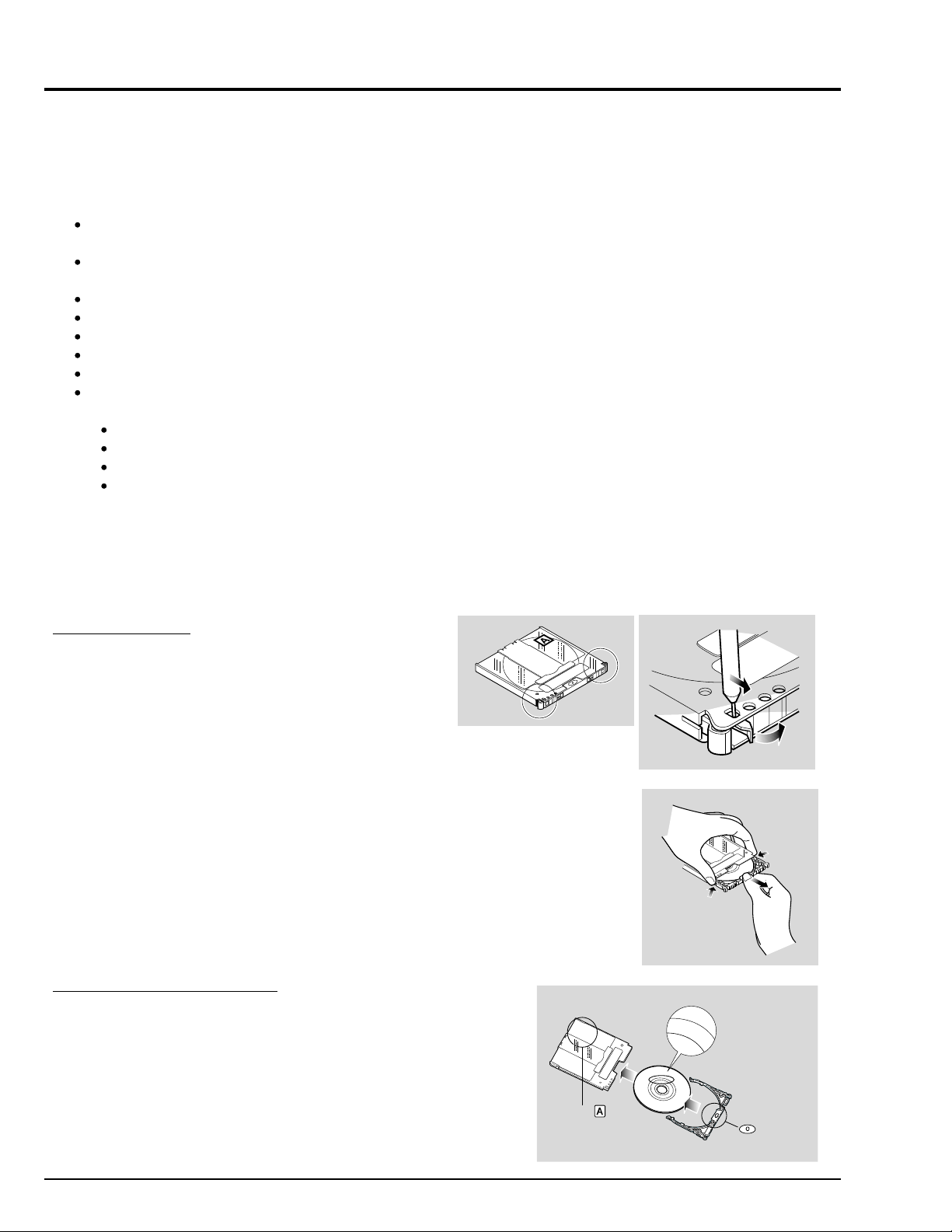
Perform the following to remove the disc provided:
Removing the disc
1) Release the lock pins of cartridge.
The two lock pins are at the bottom left
corners of sides A and B.
Use a fine tipped pen to slide the lock
pin in the direction of arrow (1)
and then turn it in the direction of arrow
(2) to release it.
2) While pushing the release levers from both
sides inward, hold the center of disc tray
and pull it out to the front.
Replacing the disc in cartridge
1) Insert the disc into cartridge.
2) Fit in the disc tray until a click is heard.
E1 - 4
Indication of side
S
I
D
E
1
A
2
Tip:
The side that will be recorded when SIDE A of disc faces the hand strap is the
opposite side to the "SIDE A" indication.
Cautions:
Laser
A
side A
indication of
disc
Most generally available 8 cm DVD- RAM discs can be removed from cartridges
if they are for video cameras; However, before removing disc from cartridge,
read the instruction sheet provided with the disc or consult the disc maker.
Surface to
be recorded
Take care with the following when handling the removed disc:
Be sure not to touch disc surfaces.
Be careful not to drop the disc removed from cartridge.
Be sure not to bend the disc.
Do not leave the disc outside the cartridge.
Do not subject the disc to heat.
Do not write on disc with a ball- point pen or pencil.
Be sure not to wipe disc surfaces with thinner,water or anti- static agent.
Use dry, soft cloth to lightly wipe off dust or dirt that adheres to the disc. Never use solvents to clean the disc.
If the disc is removed from cartridge and the data stored by this DVD video camera/recorder is rewritten on devices other
than this DVD video camera/recorder,recording or playback may not be normal,or Disc Navigation may not operate
normally,when the disc replaced in cartridge is used on this DVD video camera/recorder again.
The cartridge protects the surfaces of disc on which high- density recording is possible.Once removed from cartridge, the
disc can be replaced in the cartridge and used with this DVD video camera/recorder, but be sure to observe the
following:
Before replacing the disc in cartridge, make sure that disc surfaces are not scratched,and that no dirt or fingerprint
adheres to them.
Do not record,edit or delete on the disc when scratches, dirt or fingerprints cannot be removed even if disc surface is
cleaned.
When replacing the disc in cartridge, insert it until a click is heard.
Writing similar to recording is be performed even with simple editing or deletion. Make sure that editing or deletion has
been securely performed with the disc removed from cartridge.
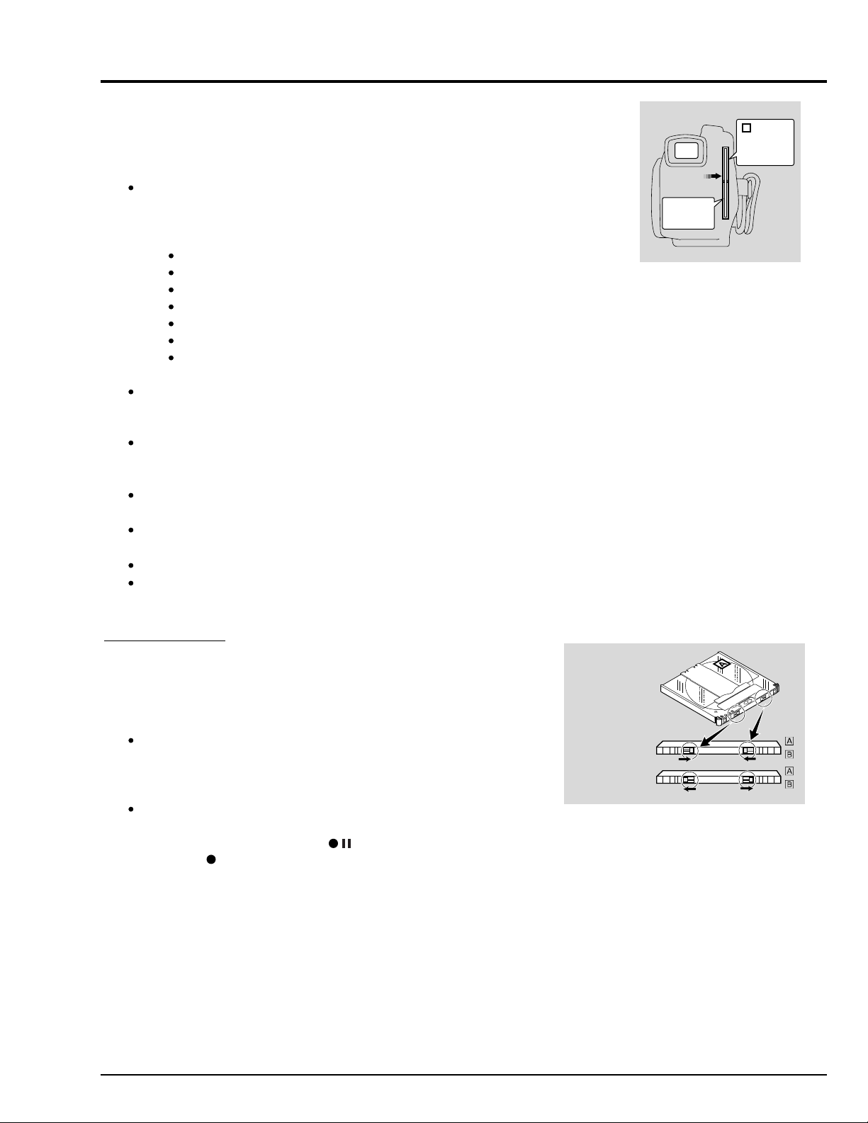
Write-protect tabs
The DVD-RAM disc cartridge has write-protect tabs to prevent overwriting
on recorded data. Make sure that the write-protect tab is set to the side
where recording is possible.
Cautions:
Dust, scratches or dirt on the disc surface may cause block noise
because of the principle of disc recording. This does not indicate a fault.
Be careful when handling the disc so that no dirt or fingerprints adheres
to the disc.
This DVD video camera/recorder has a function that allows recording,
avoiding portions of the disc with dust, scratches or dirt [The DVD video
camera/recorder sets to pause ( ) status and automatically restarts
recording ( REC )] .
This will interrupt recording for several seconds to several minutes, and
multiple thumbnails will be created in one recording as shown in the
figure. In this case, the recordable time will decrease.
Recording not possible
Recording possible
Side B
Side A
E1 - 5

3. Subsidiary Functions for Servicing
Caution: This information deals with functions exclusively used for servicing (not disclosed to persons other than service
engineers): Do not disclose the information to customers.
Activate the functions with power on and LCD monitor open (LCD on-screen information display).
3.1 Forced disc formatting
Purpose:
To initialize without starting Disc Navigation
Pertinent case:
It is desired to initialize the disc, but the data on disc has been destroyed (without physical damage to disc) and Disc
Navigation will not start.
Operation procedure:
1) Insert the disc to be formatted.
2) Hold down the following 3 buttons simultaneously for at least 3 seconds:
SHIFT button
CANCEL button
LCD BRIGHT button
3) Follow the instructions on LCD screen thereafter.
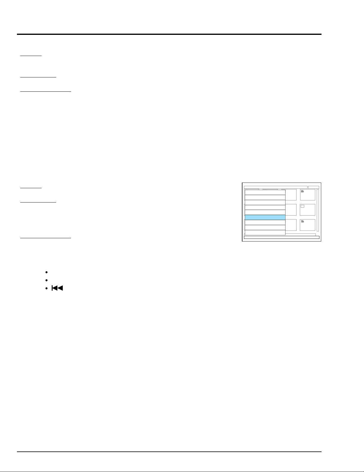
3.2 Still (JPEG) file operation (Fig. 3-1)
Caution: Executing this operation Will delete all still files on disc: Copy necessary still
files to PC, etc.
Delete all stills
Recorded info.
Purpose:
To delete still (JPEG) files to be played back on PC from the disc without using PC.
[When recording stills, this DVD video camera/recorder stores both stills to be played
back on the video camera/recorder and stills to be played back on PC: Only the still
files to be played back on the video camera/recorder can be deleted using the normal
video camera/recorder operation (Disc Navigation).]
Pertinent case:
Complaint by customer that "the disc storage capacity will not increase even if still files
are detected".
Operation procedure:
1) Insert the disc whose still files are to be deleted, and press the DISC NAVIGATION
button to start Disc Navigation.
2) Simultaneously press the SHIFT and MENU buttons to display the hidden menu on
the screen (see Fig. 3-1).
3) Use the cursor button to choose "Delete all stills", and press the ENTER button.
4) Follow the instructions on LCD screen thereafter.
Notes: 1. If "Recorded info." is selected on the hidden menu screen, the types
and numbers of files recorded on disc will appear on the screen.
2. Press the CANCEL button to exit the hidden menu and recorded
info. display, and restore normal status.
Fig. 3-1 Example of Display
E1 - 6

3.3 Firmware version display (Fig. 3-2)
Purpose:
To display the versions of software programs recorded on the following microprocessors in product (see Fig. 3-2):
System control (SH) microprocessor: $Revision
Camera control microprocessor: Cam Ver
Disc drive (PC1) main microprocessor: PC1 Main
Disc drive (PC1) core microprocessor: PC1 Core
Pertinent case:
When you are asked for checking by the factory, or you want to ask the factory about
the servicing method.
Operation procedure:
Press the following 3 buttons simultaneously:
SHIFT button
DISC NAVIGATION button
(forward search) button
Notes: 1. Operation (display) is possible without disc inserted.
2. Press the CANCEL button to exit the version display, and restore the
normal status.
3.4 Error code display (Figs. 3-3, 3-4, 3-5)
Purpose:
To investigate the error code when error message “DISC” appears on the LCD screen.
Pertinent case:
When you are asked for checking by the factory, or you want to ask the factory about
the servicing method to.
Operation procedure:
1) Make sure that camera image appears.
2) Press the DISPLAY button, and then, within 0.5 second, hold down the DISPLAY
button and (STOP) button for at least 3 seconds.
3) The screen shown in Fig. 3-3 will appear (this has nothing to do with this function):
Press the ENTER button to display the screen shown in Fig. 3-4. The numerals or
letters displayed in the C and D columns of RECVBUF row in Fig. 3-4 constitute
the error codes.
If the ENTER button is pressed from the screen in Fig. 3-4, the screen in Fig. 3-5
will appear (this has nothing to do with this function).
Notes: 1. Operation (display) is possible without disc inserted.
2. Simultaneously press the Display and STOP buttons to exit the
error code display, and restore normal status.
3. Each time the ENTER button is pressed from the screen in Fig. 3-3,
Fig. 3-4 will switch to Fig. 3-5 and then to Fig. 3-3. (Fig. 3-3 and 3-5
have nothing to do with this function).
DZ-MV100A
$Revision: 9.99
$Data: 2000/12/31 23:59:00 $
Cam Ver: 9. 09.z
PC Main: Z99Y. 88. 77. REV
PC Core: A11B. 22. 33. REV
Fig. 3-2 Example of Display
Z9Y9 99 00/12/31 V9.99Z
S 99 88 C 77 77 A 6Y 6Y
ABC012 345678D9EF01GH23
ABC012 345678D9EF01GH23
ABC012 345678D9EF01GH23
Fig. 3-3 Example of Display
Z9Y9 99 00/12/31 V9.99Z
CAM 99 88 AF 7Z 7Z 66
RECVBUF 0123456789ABCDEF
Fig. 3-4 Example of Display
0000001000AB
0000001000AB
0000001000AB
Error Codes
0012
0012
0012
Z9Y9 99 00/12/31 V9.99Z
CAM 99 88 AF 7Z 7Z 66
SENDBUF 0123456789ABCDEF
Fig. 3-5 Example of Display
9876543210CD
1234567890AB
0102030405
5060708090
0012
0034
123456
789012
E1 - 7
3.5 Playback file detailed information display
Purpose:
To display the program/play list number, scene number, bit rate, elapsed time and
elapsed position of the movie or still file being played back.
Pertinent case:
Used as a reference to find noise that occurs in the middle of a long recorded movie.
Operation procedure:
1) Insert the object disc and play it back.
2) Press the DISPLAY button to display the ordinary playback information (display the
operation mode for 3 seconds).
3) Quickly press the SHIFT button and then DISPLAY button.
Note: Press the CANCEL button to exit the playback file detailed information display,
and restore normal status.
3.6 Deleting information control (RX) file (Fig. 3-6)
Caution: This operation will delete information on all settings of skip, fade, title, etc. on
disc.
Purpose:
To erase the RX file, which controls and contains the information on thumbnails, etc.
Pertinent case:
1) Thumbnails cannot normally be displayed using Disc Navigation, or
2) "DISC ALMOST FULL" appears even if the disc has sufficient free space.
Note: The above defect may occur if power is shut off while data is being written to
the file.
Operation procedure:
1) Insert the disc whose RX file is to be deleted, and press the DISC NAVIGATION
button, making sure that the DVD video camera/recorder enters the disc navigation
mode.
2) Simultaneously press the following three buttons:
SHIFT
DISC NAVIGATION
(
reverse skip search)
3) A hidden menu will appear: Use the cursor button to choose “Delete RX file”, and
then press the ENTER button. (see Fig. 3-6)
Note: The following shows function items other than Delete RX file that the hidden
menu contains:
Version: Same as in “3.3 Firmware version display”
ErrorCode: Same as in “3.4 Error code display”
Switch Diap Temp: Invalid
Staff: Staff roll display
Switch Scene No. Color: nvalid
Format 1: Same as in “3.1 Forced disc formatting”
Japanese/English: Switching the language to be displayed on
screen. When power is supplied again
after switching, some parts of on-screen
information will alternate between English
or Japanese.
Version
ErrorCode
Switch Disp Temp
Staff
Switch Scene No. Color
Delete RX file
Format 1
Japanese
English
Fig. 3-6 Example of Display
E1 - 8

4. Explanation of Trouble Messages
A message may appear while you are operating the DVD video camera/recorder. If a message appears, refer to the following
table and take appropriate corrective action.
Message
Control info. error
Disc error
No more scenes
Play List was deleted
Write protected
Check cartridge
Battery is low
Please charge battery
Cannot combine
Select multiple
scenes
Cannot combine
Deselect stills
Scenes over limit
Cannot divide
Scenes over limit
Cannot add scenes
Cause
Mismatch may occur
between the recorded
image and scene infor
mation.
Disc may be dirty.
Mismatch in recording
information may be caused
by editing done on some
device other than this DVD
video camera/recorder.
Disc may be dirty.
All scenes are unloaded
from the play list.
-----
-----
-----
-----
The number of entered
scenes has reached the
limit that can be entered.
The number of scenes
entered in play list has
reached the limit that can
be entered.
Troubleshooting
Update the control information.
Remove the disc and wipe off
fingerprints, dust, etc. before
reusing it, or use another disc.
Initialize the disc or use
another disc.
Remove the disc and wipe off
fingerprints, dust, etc. before
reusing it, or use another disc.
-----
Release write-protect of
cartridge.
Replace with a charged
battery.
Select a range of at least 2
scenes to be combined, and
then combine them.
Select only movies and
combine them.
Delete (unload) several
scenes.
Unload several scenes.
Technical explanation
This appears when editing,
etc. was performed near the
limit (999 scenes or 13MB) of
media on devices other than
this DVD video camera/
recorder, or on user operated
control files. (*1)
The message appears when
reading recorded files or
writing data to files is not
possible. If the message still
appears after the disc is
replaced with normal one,
there is a problem in the DVD
video camera/recorder.
This appears when user is
operating information (control)
files.
The message appears when
reading recorded files or
writing data to files is not
possible. If the message still
appears after the disc is
replaced with normal one,
there will be nay problem in
the DVD video camera/
recorder.
If all scenes have been
removed from play list on the
play list select or editing
screen, the play list will
automatically be deleted, and
then this message will appear.
This appears with write
protected disc when some
writing to disc, such as
addition, deletion of scenes,
etc., is to be executed.
If the battery remaining level is
the same as the indication of
battery mark blinking during
editing, this message will
appear and editing will not be
possible.
This is an issue on operation.
This appears when stills are to
be combined and the still
combining function is not
installed.
This appears if scene is to be
divided (increased) when the
number of scenes has reached
the upper limit of 999. (*1)
This appears when the
number of scenes has reached
999 and scenes are still to be
added to play list. (*1)
Faulty or
not
Error on
disc
Same as
above
Same as
above
Same as
above
None
None
None
None
None
None
None
E1 - 9

Message
Cannot remove scenes
Cannot delete scenes
Please update disc
Disc id full
Reformat for camera
Continue?
Error on disc
All data will be deleted
Continue?
Cause
This may occur when
scene that was edited for
division, etc. is to be
unload.
This may occur when
scene that was edited for
division, etc. is to be
deleted.
The thumbnail at the start
of program or play list may
not appear when disc
edited on device other
than this DVD video
camera/recorder is used,
or, when editing, such as
combining, is performed on
this DVD video camera/
recorder.
The number of entered
scenes has reached the
limit that can be entered,
so the control information
for generating thumbnails
cannot be added.
Has the disc been initialized on a PC?
Has initializing the disc on
a PC been interrupted?
Troubleshooting
Combine the divided scenes,
and then unload them.
Combine the divided scenes,
and then delete them.
If thumbnail is information is
insufficient, Disc Navigation
will automatically create
thumbnails after it starts.
Combine several scenes or
delete (unload) them.
Choose "Yes" and initialize the
disc when using it on this DVD
video camera/recorder.
Technical explanation
This appears if CELL is to be
divided (increased) when the
number of CELLs has reached
the limit of 999. (If recording
continues without editing on
this DVD video camera/
recorder, 1 scene will make up
1 EP or 1 CELL. If scenes are
combined, the number of EPs
will decrease, but the number
of CELLs will not decrease. If
CELL is to be divided at the
upper limit number of CELLs,
several scenes must be
deleted in this status without
traversing multiple CELLs. (*2)
Same as above.
This appears if a disc in which
EP is not attached to the
beginning of program or play
list is inserted (this occurs
when EP was not attached to
the beginning of program or
play list when editing was
performed on devices other
than this DVD video camera/
recorder, or scenes traversing
multiple programs were
combined, and thumbnails
cannot be displayed on Disc
Navigation screen). This
message appears when Disc
Navigation is started first after
power is supplied: Operation
following message instructions
will attach EP to the beginning
of program or play list, thereby
enabling thumbnails to be
displayed.
This appears if the number of
scenes has reached 999 when
control information is being
updated. (*1)
This appears if the disc has a
file that has been recorded in
a format that cannot be
detected by UDF2.0. (This
problem will be solved if the
disc is formatted on this DVD
video camera/recorder.)
This appears if the disc has
logically been destroyed. (The
problem frequently occurs
because of problem in the
UDF file system.) Although the
disc for which this message
appeared cannot be used as
is, it may be usable after it is
initialized (Note, however, that
all recorded data will be
deleted).
Faulty or
not
None
None
None.
However,
the disc
has a
problem in
compatibility.
None
Error on
disc
Error on
disc
E1 - 10

Message
Disc error
Failed format
Disc error
Keep disc inside and
restart
Disc full
Cannot execute
Drive heat too high
Please retry later
(1) Error Reading
Repair movie file?
(2) Error Reading
Repair movie file?
(3) Error occurred
Try to fix
Standby Continue?
Cause
The disc may be dirty.
Disc error could have
occurred during editing of
scenes.
-----
The temperature inside the
DVD video camera/
recorder is too high, and
reading or writing of the
data on disc may not be
performed normally.
It is possible that the
system cannot normally
complete writing of file
when power is turned off
for some reason during
recording or editing
(deleting, dividing or
combining scenes, or
creating play list). Selecting
"Yes" will automatically
repair the video file, but
even if "No" is selected,
the same message will
appear when the DVD
video camera/recorder is
turned on next time. (Do
not remove the disc while
the DVD video camera/
recorder is recognizing it:
lqnoring this will deactivate
the file repair function.)
Troubleshooting
Remove the disc and wipe off
fingerprints, dust, etc. before
reusing it, or use another disc.
Turn off the DVD video
camera/recorder with the disc
being used in it, connect AC
adapter/charger, and then
power the DVD video camera/
recorder again. Scenes will be
repaired.
Delete unnecessary scenes
before using this disc, or use
another disc.
Turn the DVD video camera/
recorder off and wait for a
while. The temperature will be
effectively decreased if the
DVD video camera/recorder is
placed in a well-ventilated
spot.
Follow the instructions on
screen, taking note of the
following cautions:
Data may not be repaired,
depending on the timing
when power was turned off.
Data may not be repaired
normally if data recorded on
another recorder is mixed in.
The repaired data may be
different from the original
recorded content because of
partial deletion of defective
portion.
Since the date/time for repair
is added to the repaired data
(only the corrected portion
for partial repair), the original
date/time information will be
lost.
Since all movies, and then all
stills, are repaired, the order
of recorded contents will be
lost.
(In case of message (3) only)
Technical explanation
This appears if formatting of
disc could not be normally
performed (writing could not
be done to specified address).
This appears if power is shut
off for some reason during
movie recording. This DVD
video camera/recorder has a
function that automatically
saves files if power is shut off
during movie recording: This
function will repair some files
when the DVD video camera/
recorder is restarted (it may
take 10-20 minutes to repair
files). The DVD video camera/
recorder must be stably
powered using AC adapter for
restart.
This may appear if some
operation, such as adding
thumbnails, etc., is attempted
when the recordable area on
disc has been nearly used up.
This appears if recording,
playback, etc. is performed in
an environment near the limit
of allowable operating temperature (humidity) for an
extended time. This message
will not appear in ordinary
situations of use, and reliability
of recorded data will decrease
in a situation where this
message appears.
This DVD video camera/
recorder has a function that
automatically saves files if
power is shut off during movie
recording: This function will
repair some files when the
DVD video camera/recorder is
restarted (it may take 10-20
minutes to repair files), and the
message will appear at this
time. The DVD video camera/
recorder must be stably
powered using AC adapter for
restart.
Same as above
Same as above
Faulty or
not
Physical
defect on
disc
Error in
recorded
file layer
on disc
None
None
Basically,
none
Same as
above
Same as
above
E1 - 11

Message
Use AC adapter
Error occurred
Please charge/format disc
*1: The number of recordable scenes on this DVD video camera/recorder is 999: Since the maximum number of EPs (record
ing points) defined by the RTR standard (DVD-RAM recording standard) is 999, and 1 EP is allocated to 1 scene, this
limitation exists.
*2: The number of recordable CELLs (minimum recording unit) on this DVD video camera/recorder is 999. This limitation
exists because the maximum number of CELLs defined by the RTR standard (DVD-RAM recording standard) is 999.
Cause
Scene cannot be repaired
when the DVD video
camera/recorder is
powered by a battery.
Abnormality with the disc
to be repaired.
Troubleshooting
If the AC adapter/charger is
unavailable in handy place,
remove the disc, use the
opposite side, or use another
disc. To repair the removed
disc, insert the disc into the
DVD video camera/recorder
afterwards, and connect the
AC adapter/charger.
Initialize the disc before using
it again, or use the other side
of the same disc or another
disc.
Technical explanation
This DVD video camera/
recorder has a function that
automatically saves files if
power is shut off during movie
recording: This function will
repair some files when the
DVD video camera/recorder is
restarted. Since it may take
10-20 minutes for file repair
work, the DVD video camera/
recorder must be stably
powered using AC adapter:
The message will appear at
this time. Note that if power is
again shut off while files are
being repaired, restoration of
those files being repaired will
no longer be possible.
This message appears if there
is a problem in the disc or in
this DVD video camera/
recorder. If the problem is not
resolved after multiple tries of
troubleshooting on the left, the
problem is in the DVD video
camera/recorder.
Faulty or
not
None
Basically,
none
E1 - 12

5. Troubleshooting Guide of DVD Video Camera/recorder
Cautions: 1) This DVD video camera/recorder incorporates a laser emitter block and high-voltage section:
Take great care when performing work.
2) Disassemble and reassemble the DVD video camera/recorder according to "Chapter 2 Disassembly".
Do not dismantle the R block any farther than the status shown in Fig. 5-1.
3) Be careful not to short-circuit TL (test land), IC pins, etc. during work.
4) Use the frame of ANA or DIG circuit board for GND.
The whole circuit board must be replaced in the following cases because components of these circuit boards are not available
as service parts. Judge whether the circuit boards shown below are defective, referring to the troubleshooting guide on the
following pages:
ANA circuit board
DIG circuit board
PHD circuit board [to be replaced together with mechanism unit] on R-block (drive block).
Notes: 1) Use the specified "check points" only for reference: Estimate the "Troubleshooting due to check results" method
from the "symptom" and try replacing circuit boards, components, etc., as needed.
If it is absolutely necessary to confirm check points, etc., pull them out from circuit boards using lead wires, etc.
2) This troubleshooting guide describes only major defects: The listed causes of defects and troubleshooting may not
always apply.
3) Troubleshooting guide assumes that connectors are correctly connected and that cables are not damaged or
disconnected: Make sure that all connectors and cables are correctly connected, and that they are not damaged.
4) This troubleshooting guide assumes that disc is normal. If there is any abnormality in disc, a trouble message will
appear: Perform appropriate troubleshooting, referring to “Explanation of Trouble Messages” described previously.
5) For check point locations, refer to the circuit board diagram shown in Chapter 6.
Letters in brackets [ ] show the names and sides of circuit boards:
Examples: ANA-A: Side A of ANA circuit board
DIG-B: Side B of DIG circuit board
B
A
A : R-Block (Drive Block)
B : PHD Circuit Board
(Mechanism Unit)
C : DIG Circuit Board
D : ANA Circuit Board
E : SE Circuit Board
F : GYR Circuit Board
G : JKR Circuit Board
H : JKF Circui Board
I : Flash Circuit Biard (Flash Unit)
J : GND
F
H
E
G
I
J
C
D
Fig. 5-1 Parts Locations
E1 - 13
Symptom
No power
No information appears on
screen after pressing DISPLAY button: POWER switch
does not work.
No operating sound
No sound from speaker
No audio from audio output
jack
Microphone sound cannot be
recorded
Sound from external microphone cannot be recorded
No sound can be recorded
Speaker sound volume
cannot be adjusted
Operation switches on side
case L do not work
Zoom switch does not work
EJECT switch does not work
Check point
L0501 [ANA-A]
F0502 [ANA-B]
(*1)
L0509 [ANA-A]
L0504 [ANA-A]
TL0520 [ANA-B]
(*1)
TL1523 [ANA-B]
(*1)
L0502 [ANA-A]
L0503 [ANA-A]
L0505 [ANA-A]
L0510 [ANA-A]
L0511 [ANA-A]
C0546 [ANA-A]
TL1501 [ANA-A]
----Red and blue wires
of the MV100
connection jig.
-----
IC4001-2 [DIG-A]
PG6301 [ANA-A]
(speaker connector)
TL6301 [ANA-A]
TL6302 [ANA-A]
TL1701 [ANA-A]
TL1702 [ANA-A]
PG6001 [JKR-A]
TL6091 [JKR-B]
TL6092 [JKR-B]
Microphone jack
(JK6051) [JKR-B]
-----
-----
PG1503-4 [ANA-A]
PG1503-5 [ANA-A]
TL1503 [ANA-A]
TL1501 [ANA-A]
Detail of check
Continuity check
"Hi" when power turns on
Approx. 3V DC (SYS3V)
Approx. 3V DC (CAM3V)
Approx. 5V DC (CAM5V)
Approx. 1.8V DC (CAM1.8V)
Approx. 3V DC (DRV3V)
Approx. 5V DC (DRV5V)
Approx. 15V DC
Voltage varies when POWER
switch is turned on/off.
Connections of switch unit.
Red and blue wires are "Hi".
Connect jigs in the same way
as for adjustment, and start
adjustment program (only
startup is necessary, adjustment is not necessary).
Goes "Hi" momentarily when
power is turned on (SH-RST
pulse).
Check connections.
Audio signal
Audio signal
Check connections
Audio signal
Connection of external
microphone
Sound is output from speaker.
Volume indicator on screen
operates.
Switch operation changes
voltage.
Switch operation changes
voltage.
Troubleshooting due to check results
NG: F0501 (fuse) faulty. Replace ANA
circuit board.
NG: F0502 (fuse) faulty. Replace ANA
circuit board.
NG: F0503 (fuse) faulty. Replace ANA
circuit board.
NG: F0504 (fuse) faulty. Replace ANA
circuit board.
NG: IC1501 faulty. Replace ANA circuit
board.
NG: IC1503 faulty. Replace ANA circuit
board.
NG: IC0501 or its peripheral circuits
faulty. Replace ANA circuit board.
NG: Check connections of switch unit.
OK: IC1501 or peripheral circuits faulty.
Replace ANA circuit board.
OK: Replace switch unit
NG: IC4001 faulty. Replace DIG circuit
board.
NG: IC4002 faulty. Replace DIG circuit
board.
NG: IC1501 faulty. Replace ANA circuit
board.
OK: IC4001 faulty. Replace DIG circuit
board.
NG: Connector connections faulty.
OK: Replace side case L (speaker).
NG: IC6301 or its peripheral circuits
faulty. Replace ANA circuit board.
NG: IC6103 or its peripheral circuits
faulty. Replace ANA circuit board.
OK: Check parts on JKR circuit board.
NG: Connector connections faulty.
OK: Replace microphone.
NG: Check IC6001, IC6091 and their
peripheral circuits.
OK: Replace ANA circuit board.
NG: External microphone connection
faulty. JK6051 contact faulty.
OK: Check Q6051 R/L and their
peripheral circuits.
NG: IC6301 faulty. Replace ANA circuit
board.
OK: IC5001 faulty. Replace DIG circuit
board.
NG: Replace switch unit.
OK: IC6301 faulty. Replace ANA circuit
board.
NG: Replace side case-L.
OK: CAM3V line or IC1501 faulty.
Replace ANA circuit board.
NG: Replace switch unit.
OK: IC1501 or its peripheral circuits
faulty. Replace ANA circuit board.
*1: Solder lead wire, etc. to check point for measurement.
*2: Perform measurement with GYR circuit board removed.
E1 - 14

Symptom
Date is not backed up
No display in information LCD
(B/W)
Does not enter REC PAUSE
status
No image in EVF
Great block noise during
movie recording
Error message "DISC ACCESS" appears and disc is
not recognized.
Noise appears on Disc
Navigation screen
Error message "Error occurred" appears
Error message "NO DISC"
appears even when normal
disc is inserted
Error message "CHECK
DISC" appears
Error message "DISC"
appears
Error message "Reformat for
camera. Continue?" appears
Camera image is abnormal
Camera image distorted (sync
faulty)
No video from video output
jack
Check point
TL1518 [ANA-A]
TL3704 [DIG-A]
-----
TL1509 [ANA-A]
R3841 [ANA-A]
-----
-----
-----
-----
-----
-----
-----
-----
-----
TL1003(*2) [SEN-B]
TL1004(*2) [SEN-B]
TL1005(*2) [SEN-B]
TL1006(*2) [SEN-B]
TL1016(*2) [SEN-B]
TL1017(*2) [SEN-B]
TL1001(*2) [SEN-B]
IC1512-1 [ANA-A]
-----
TL1712 [ANA-A]
Detail of check
3V DC when power supply is
not connected.
Pulse (CS-PNL signal)
Check damage to cable
between LCD power unit and
DIG circuit board
"Hi" when power turns on
(SYS-RST pulse).
Signal (G signal)
-----
Error message does not
disappear and POWER switch
does not work.
Error message does not
disappear after 3 seconds or
more.
-----
-----
No improvement after DIG
circuit board is replaced.
Error message appears
approx. 1 second after disc is
inserted.
Error message appears at
least 10 seconds after disc is
inserted
Disc cartridge is writeprotected
-----
Normally initialized disc was
inserted
Check CCD sensor drive
pulses
Check CCD output signal
27MHz clock signal (SYSCLK)
Image appears in LCD or
EVF.
0V when AV output cable is
connected
Troubleshooting due to check results
NG: Check backup lithium-ion batter and
JKR circuit board.
OK: IC1501, IC1504 or their peripheral
circuits faulty. Replace ANA circuit
board.
NG: IC1501 faulty. Replace ANA circuit
board.
OK: Check cable between LCD power
unit and DIG circuit board.
NG: Replace side case L.
OK: Replace LCD power unit.
NG: IC1501 faulty. Replace ANA circuit
board.
OK: IC4001 faulty. Replace DIG circuit
board.
NG: IC3801 faulty. Replace ANA circuit
board.
OK: Check flat cable between EVF and
ANA circuit board.
Movie encoder circuit faulty. Replace DIG
circuit board.
F0503 (fuse) faulty. Replace ANA circuit
board.
Yes: IC4001 (ATAPI system) or IC2001
(CODEC system) faulty. Replace
DIG circuit board.
No: Check connections between DIG
circuit board and mechanism unit.
IC4001 or clock circuit for IC4001 faulty.
Replace DIG circuit board.
IC4001 (ATAPI system) or IC2001
(CODEC system) faulty. Replace DIG
circuit board.
Replace mechanism unit.
Check connections between DIG circuit
board and mechanism unit. If no abnormality is found, replace mechanism
block.
Replace mechanism unit.
Yes: Release write-protect.
No: Replace mechanism unit.
Initialize the disc.
Yes: Replace mechanism unit.
No: Initialize disc.
NG: Check connections between SEN
and DIG circuit boards. If there is no
abnormality, replace DIG circuit
board.
NG: Replace IC1001 (CCD sensor)
NG: IC1511 faulty. Replace ANA circuit
board.
OK: IC1401 faulty. Replace DIG circuit
board.
Yes: Check connections between ANA
and JKR circuit boards.
No: Replace ANA circuit board.
NG: Check AV input/output jack
(JK1981).
OK: IC1701 faulty. Replace ANA circuit
E1 - 15

6. Updating Firmware
Firmware Update
Do not turn off po
wer
Firmware Update
Do not turn off po
wer
Firmware Update
Do not turn off po
wer
Firmware Update
The Firmware Update function updates the software programs in the DVD video camera/
recorder, to improve operability:
Update the firmware whenever so instructed by the factory (using exclusive DVD-RAM
disc supplied by the factory).
Caution: Be sure to check the version of firmware, referring to “3.3 Firmware version
display” of “3. Subsidiary Function for Service” in this chapter, and update the
firmware only if updating is necessary.
6.1 Firmware programs
The DVD video camera/recorder has the following firmware programs:
SH firmware
Software that drives the SH-type CPU: It controls operation of the entire
system, including recording, playback, Disc Navigation, PC connection, etc.
PC1 main firmware / PC1 core firmware
Software that drives the DVD-RAM (referred to as PC1)
Camera microprocessor firmware (updating unnecessary)
Controls the basic settings of system, including DSP camera block (optical
system), time, battery, input/output selection, etc.
6.2 How to update
The firmware can be updated by simply setting the DVD-RAM disc (developed exclusively
for updating) in the video camera/recorder (the DVD-RAM disc will be supplied by the
factory).
1) Connect the AC adapter to the video camera/recorder, insert the firmware updating
disc into the video camera/recorder and turn power on.
2) After approx. 20 seconds, screen 1 will appear momentarily.
3) Screen 2 will appear, and updating of mechanism (PC1) firmware will start:
It will take approx. 2 minutes to update the PC1 firmware.
Depending on the supplied DVD-RAM disc (version), the PC1 firmware may not be
updated.
4) After PC1 firmware has been updated, screen 3 will appear, and updating of SH
firmware will start.
During updating, a blue bar at the center of screen will indicate the progress of
updating.
Depending on the supplied DVD-RAM disc (version), the SH firmware may not be
updated.
5) When updating of firmware is complete, screen 4 will appear, and the updated
firmware will be displayed in blue.
6) Turn power off and remove the disc.
Firmware Update
Start firmware update
Do not turn off po
wer
Screen 1
Firmware Update
Updating drive (main)...
Wait a minute...
Do not turn off po
wer
Screen 2
Firmware Update
Uptating system...
Do not turn off po
wer
Screen 3
Firmware Update
Firmware Updated
DZ-MV100$Revition: 1.031ck1
PC1 Main: E078.09.01.REV
PC1 Core: E009.07.10.REV
Turn off power
E1 - 16
Screen 4

7. Service Manual Abbreviation List
(For DVD Video Camera/recorder)
A
A (A-) Analog
ACC Automatic Color Control
A/D Analog-to-Digital Converter
ADD Adder
ADP. Adapter (AC Adapter)
ADRS Address
A.DUB Audio Dubbing
AF Automatic focus (Autofocus)
AFC Automatic Frequency Control
AGC Automatic Gain Control
AGC KILLER AGC Killer Voltage
AI Automatic Intelligence
AIC Automatic Iris Control
ALC Automatic Level Conrol
AMP Amplifier
APC Automatic Phase Control
ASBL Assemle (Phase Matching)
AUD. Audio
AUX Auxiliary
B
B (BLU) Color Signal Blue
BATT. Battery
BF Burst Flag
BG Burst Gate or Back Ground
BGP Burst Gate Pulse
BLC Backlight Compensation
BLK Blanking
BPF Bandpass Filter
BUF. Buffer Amplifier
B-YL Color Difference Signal B-YL
C
C (CHROMA) Chrominance Signal
CAM Camera
CARRI. Carrier
CATV Cable TV
C.BLK Composite Blanking
CCD Charge Coupled Device
CD Compact Disc
CD-R CD Recordable
CD-RW CD ReWritble
CDS Correlated Double Sampling
CG Character Generator
CH (Ch or ch) Channel
CHARA. Character
CHD Camera Horizontal Drive Pulse
C.MEMORY Counter Memory
CNR Chroma Noise Reducer
COM. Common
COMPA. Comparator
COMPE. Compensator
COMP-EXP Compressor-Expander
COMPO Composite
CONT. Control
CONV. Converter
COUNT. Counter
CP CP
CPU Central Processing Unit
C.PAUSE Camp Pulse
C/R Capacitor/Resistor
C.RESET Countor Reset or Camera Reset
C.REVERSE Count Reverse
CS Communication Signal
C.SYNC Composite Synchronizing Signal
D
D (D-) Digital
DA Double Azimuth
D/A Digital to Analog Converter
D-D Direct Drive
DEEMPHA. Deephasis
DEF Deflefction
DEMOD. Demodulator
DET Detector
DIFF. AMP Differential Amplifier
Digital 8 (D8) Digital 8 mm
DISP. Display
DL Delay Line
DO Dropout
DOC Dropout Compensator
DSP Digital Signal Processor
DUB Dubbing
DV Digital Video
DVD Digital Versatile Disc
D-VHS Digital VHS
D/W Dark/White
D.ZOOM (DZ) Digital Zoom
E
EAROM Electrically Alterable Read Only
Memory
E-E Electronic-to-Electronic
EEPROM Electrical Erasable Proframmed
Memory
EIS (E.I.S.) Electronic Image Stabilizer
EMPHA. Emphasis (EMPH)
EQ Equalizer
EVF Electronic Viewfinder
EXT. External
E.ZOOM Electrolical Zoom
F
F.ADV Frame Advance
FB Feed back
FE Full Erase
FF (F/F) Flip Flop
F.FWD Fast Forward
FG Frequency Generator
FM Frequency Modulation
FREQ. Frequency
fsc Sub Carrier Frequency
F/V Frequency-to-Voltage Converter
FWD Forward
G
G (GRN) Color Signal Green
GEN. Generator
GND Ground
H
H (HORIZ.) Horizontal
HB Hi-Band
HBF Horizontal Burst Flag
HD Horizontal Drive
Hi-Fi High Fidelity
HPF High-pass Filter
I
IF Intermediate Frequency or Interface
INDI. Indicator
INST. Instant
INT. Internal
INV. Inverter
I/O In/Out (Input/Output)
E1 - 17
I
IR Infrared Rays
J
JPEG Joint Photographic Experts Group
L
LB Low-Band
LCD Liquid Crystal Display
LIN. Linear
LNC Line Noise Canceller
LOG Logarithm
LP Long Play
LPF Low-pass Filter
L/R Left/Right
LUMA Luminance
M
MAN Manual
M.BRAKE Main Brake
M.CUT Monitor Cut
MEM. Memory
MIC Microphone
MIX Mixer
MMV Monostable Multivibator
MOD. Modulator
MPEG Noving Picture coding Experts Group
M.STATE Mechanism State
M.STOP Memory Stop
N
NEG Negative
NFB Negative Feed Back
NOR. (NORM) Normal
NR Noise Reduction
O
OB Optial Black
OSC Oscillator
OSD On-Screen Display
P
PB (PLAY) Playback
PCM Pulse Code Modulation
PG Pulse Generator
PLL Phase Locked Loop
POS. Positive
PROG. Program
PROT. Protector
PWM Pulse Width Modulation
R
R (RED) Color Signal Red
RAM Random Access Memory
REC Record
RECT. Rectifier
REF. Reference
REG. Regulator
REV Review
REW Rewind
RF Radio Frequency
ROM Read Only Memory
R-YL Color Difference Signal R-YL
S
SAW Sawtooth Signal
SC1 (0°) 3.58MHz Subcarrier Signal 1
(0-degree Phase Shifted)
SC2 (90°) 3.58MHz Subcarrier Signal 2
(90-degree Phase Shifted)
SEPA. (SEP) Separator
S/H Samle and Hold
S
SP Standard Play or Speaker
SRCH Search
SRV Servo
STABI. Stabilizer
S.TRACK Slow Tracking
STBY Standby Mode
S-VHS Super VHS
SW Switch
SYNC Synchronizing signal
SYS.CON System Control
T
T (TELE) Telephoto Angle
TAPE + Recording Hi-8 Quality Image on Normal
Tape
TBC Time Base Corrector
TP Test Point
TRS Transfer
V
V (VERT.) Vertical
V.AGC AGC Voltage
VCO Voltage Controlled Oscillator
VCXO Voltage Controlled Crystal Oscillator
VD Vertical Drive
V.DUB Video Dubbing
VHS Video Home System
VOL. Volume
VP Voltage Pulse
W
W (WIDE) Wide Angle
WHD Wide Horizontal Drive
WHT Color Sifnal White
WHT BAL. White Balance
Y
Y Luminance Signal
Y/C Luminance/Chrominance
YEL (Ye) Color Signal Yellow
YL Luminance Signal (Low Component)
E1 - 18

8. For the Battery
Be sure to use the specified battery:
Using other batteries could cause faulty video camera/recorder operation, or possibly a fire.
Store the battery in a dark, cool place:
If your store it in a place where the temperature is high, the battery life will be shortened. Especially be sure not to store the
battery in an environment (in a closed vehicle) over 140 °F (60 °C): Neglecting this could damage the battery.
Battery life:
The battery can be repeatedly charged and used, but will eventually be dead: The battery life varies greatly depending on the
ambient environment and how often the video camera/recorder is used. If the usable time of video camera/recorder with a fully
charged battery is noticeably short, the battery is probably dead.
Disposing of the dead battery:
Dispose of battery safely in accordance with local laws. Do not dispose of in fire.
Be sure not to do the following:
!
DANGER
Short-circuit battery terminals.
Disassemble or modify the battery.
Throw the battery into fire.
Cautions:
During and after charging, the battery will be warm, but this does not indicate a fault.
If the POWER indicator on AC adapter/charger blinks, remove the battery once, and then reattach it. If the POWER
indicator still blinks, the battery may be faulty.
If the ambient temperature is a little too high or low, the CHG. indicator or CHG.80 indicator on AC adapter/charger will
blink at 6-second intervals. In this case, charging is possible, but it will take longer than usual.
If the ambient temperature is too low or too high, the CHG. indicator or CHG.80 indicator on AC adapter/charger will
blink at one-second intervals, showing that charging will not be possible.
E1 - 19
9. Extract from the Instruction Manual
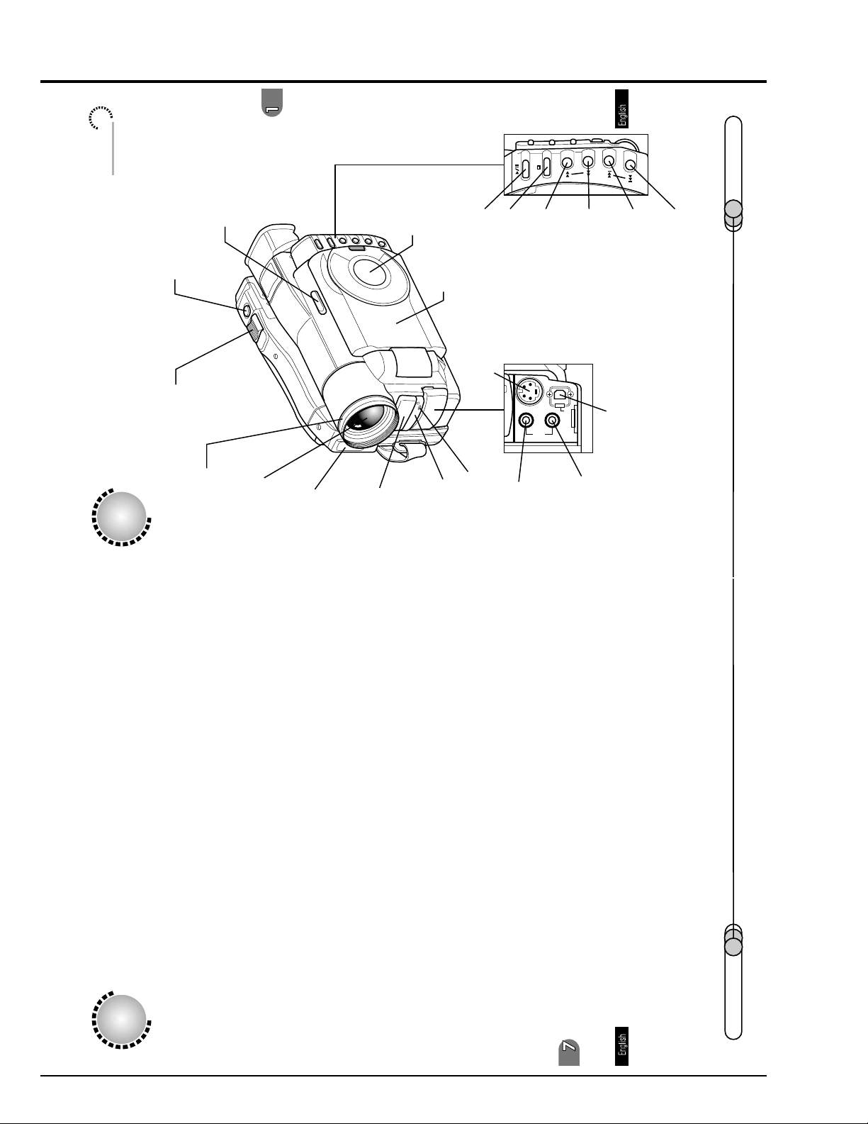
Name of Parts
RECORDING MODE
switch (P. 64,66,82)
(P. 82)
PHOTO button (shutter)
(P. 63,148)
LCD monitor
Information
color LCD monitor (P. 60)
3.5-inch
Playback/Pause
button (P. 92)
Stop button
(P. 92,93)
Forward search button
(P. 92,95)
(P. 92,93,95)
Reverse search button
Forward skip button
(P. 92,94)
29
(P. 92,94)
Reverse skip button
Names of Parts
Zoom lever
64,67)
.
(P
Lens hood
zoom lens
Optical 12X
(P. 84)
Flash
(P. 80)
microphone
Stereo
Infrared
receiver (P. 55)
input/output jack (P. 142)
S-video
Behind
(P. 89)
Tally lamp
the cover
output
AV input/
O
E
D
I
V
S
AUDIO/VIDEO
EXT.MIC
(P. 140,142)
jack
DIGITAL
External
terminal (P. 148)
PC connection
(P. 80)
jack
microphone
E1 - 20
Cleaning
Be sure to turn the POWER switch off befor e cleaning this DVD camcorder.
Cleaning LCD screen and lens:
Use dry, soft cloth to wipe dirt off. When cleaning the LCD screen, be careful not to
use force, scratch it, or subject it to impact: Doing such could cause a defect in the
screen, result in display unevenness, or damage the LCD monitor.
Do not use benzene or thinner to clean DVD camcorder case:
The coating of case could peel of f or the case could deteriorate. Wipe off dirt on the
case with a moist cloth which has been completely wrung out. When using chemical
cleaning cloth, follow instructions for use.
If dust adheres to viewfinder lens:
could damage it.
Use a cotton swab to wipe it of f. Do not use force when rubbing the lens: Doing so
150
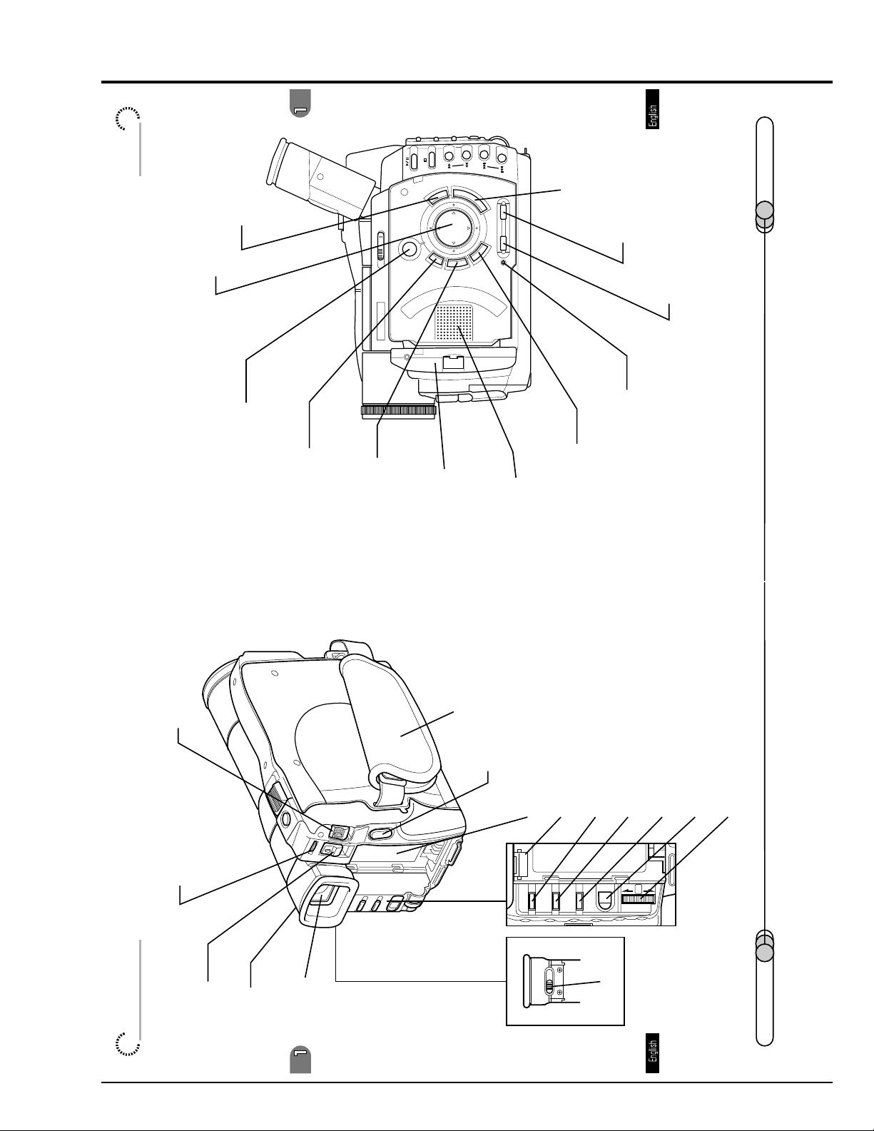
of Parts
Name
MENU button
(P. 69,101,104)
Cursor button
DISC NAVIGATION button
(P. 101)
(P. 100)
(P. 101,108,109)
DELETE button
RECORDING
MODE
(P. 101,104)
SHIFT button
31
SEARCH
SKIP
MENU
DISC
DELETE
NAVIGATION
ENTER
DISPLAY LCD BRIGHT
CANCEL
SHIFT
color LCD monitor
3.5-inch
RESET
(P. 60)
(P. 69,101,105)
ENTER button
(P. 61)
LCD BRIGHT button
DISPLAY button (P. 63,97)
(P. 134)
RESET button
(P. 101,120,121)
Speaker
CANCEL button
1_Before You Begin
chapter
(P. 47,52,59)
POWER switch
(P. 23)
ACCESS indicator
(P. 47)
button
Disc eject
(P. 59)
Eye cup
(P. 42,59)
Viewfinder
Hand strap
(P. 48,58)
REC button (P. 64,66)
Bottom
Battery attachment platform
PUSH
PROG.AE
(P. 42)
EXPOSURE
Battery eject button
FOCUS
(P. 43)
PROG AE button
MENU
(P. 64,78)
EXPOSURE button
(P. 64,72)
PUSH
(P. 59)
Diopter control
(P. 64,74,89)
FOCUS button
(P. 25,52,64)
MENU button
(P. 52,61,64,101)
Select dial (push to enter)
30
E1 - 21
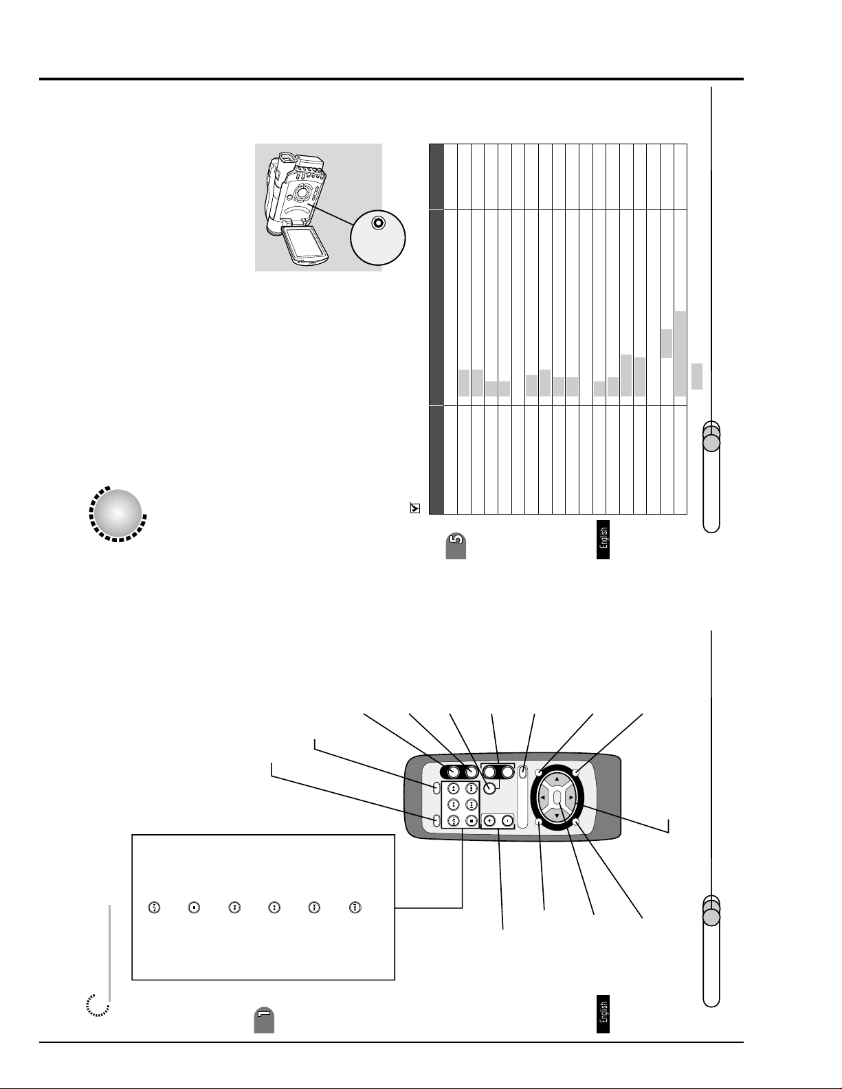
Page for setting
145
81
86,88
131
143
141
System Reset
If the DVD camcorder does not operate normally, perform "System Reset": The DVD
camcorder may recover to normal. "System Reset" will reset all settings to factory
defaults. The date and time will also be reset: Set the date and time again before
using the DVD camcorder.
charger .
1. Turn the DVD camcorder off, and detach the battery or AC adapter/
2. Use a fine tipped pen to hold down the
RESET
(0:05-5:00)
e initial settings.
1/1/2000 12:00AM52* ar
Item Settings
reset button for several seconds.
List of setting items:
FLASH AUTO/ON/OFF 84
W.BALANCE AUTO/HOLD79EIS ON/OFF73D.ZOOM ON/OFF 67
CAMERA SETUP
REC SETUP
V.QUALITY FINE/STND 77
STILL L.IN FIELD/FRAME
SELF./INT. OFF/SELF-TIMER/INTERVAL
MIC FILTER OFF/ON
BEEP ON/OFF 130
POWER SAVE OFF/ON:5/ON:30
INPUT CAMERA/LINE
OTHER SETUP
E.DISPLAY LINE ON/LINE OFF
DATE SETUP
DATE MODE Y/M/D / M/D/Y / D/M/Y 132
DATE SET
134
E1 - 22
chapter 1_Before You Begin
Playback/pause button (P. 93)
Stop button (P. 93)
Reverse search button (P. 93,95)
DISPLAY button
(P. 63,97)
Forward search button (P. 95)
EXTERNAL DISPLAY
(P. 141)
button
. 94)
Reverse skip button (P
REC button
(P. 66)
Forward skip button (P. 94)
PHOTO button
(P. 82)
EXT.DISPLAY
DISPLAY
(P. 68)
button
DIGITAL ZOOM
REC
PHOTO
SKIP
SEARCH
ZOOM button
(P. 67)
T
W
ZOOM
ZOOM
DIGITAL
VOL
buttons
VOL control
DISC NAVIGATION
MENU
DISC
NAVIGATION
DELETE
(P. 93,97)
(P. 100)
button
ENT
(P. 108,109)
DELETE button
CANCEL
HITACHI
SHIFT
(P. 68,102)
MENU button
(P. 107)
ENTER button
(P. 120,121)
CANCEL button
(P. 104)
SHIFT button
Cursor buttons
(P. 104)
32
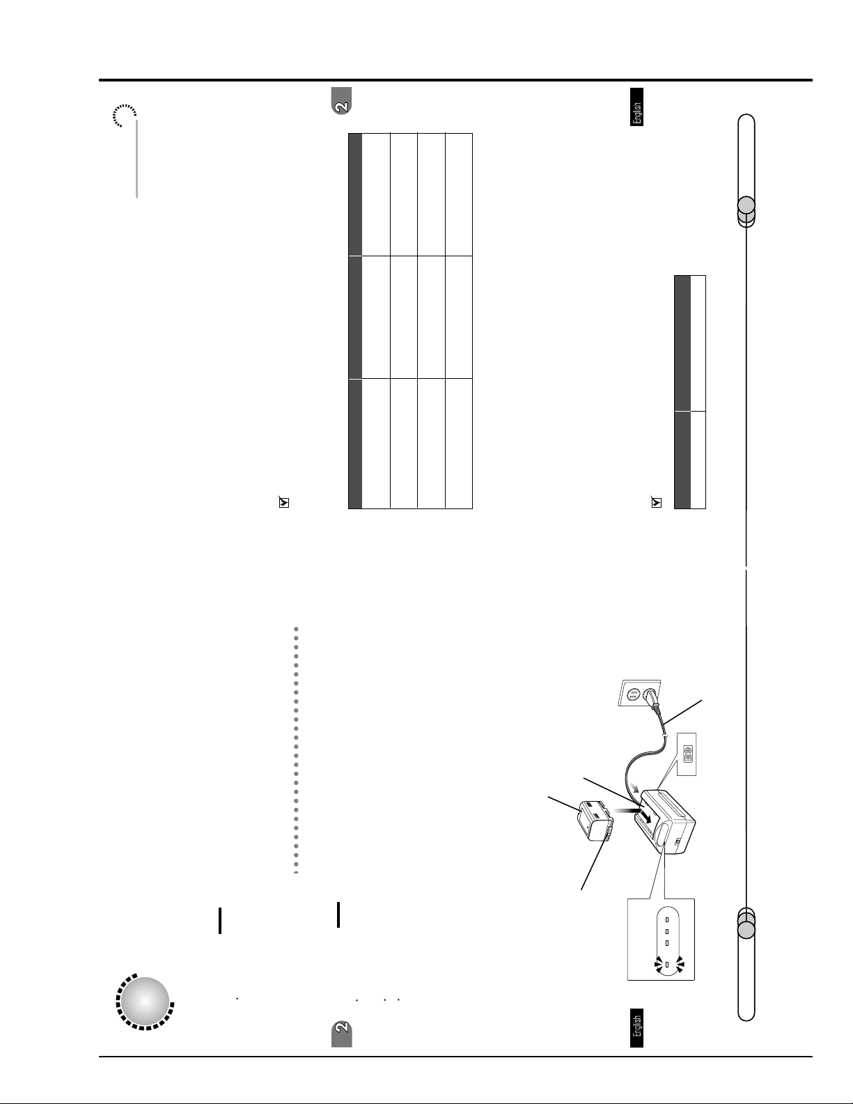
41
Setting Up the Battery
DZ-BP28 (sold separately)
DZ-BP16
(in STND mode)
dinary operation, such as zooming:
3
The time taken for charging the battery is as follows (at normal temperature):
2
DZ-BP16 DZ-BP28 (sold separately)
approx. 90 minutes approx. 170 minutes
Power cable
Orient the terminal section of battery toward the DC OUT of AC adapter/charger,
and while fitting the battery onto the charger, slide it in the dir ection of the arrow.
The CHG. indicator on AC adapter/charger will blink, and charging will start. (If
charge remains on the battery, the 80% indicator may light.)
Blinking of the CHG. indicator will change to a steady light after charging has
3. Attach the battery to the AC adapter/charger.
started. When the battery has been fully charged, the 100% indicator will light.
Continuously recordable time on camcorder with fully charged battery
When using viewfinder approx. 105 minutes approx. 180 minutes
(in FINE mode)
When using LCD monitor approx. 90 minutes approx. 150 minutes
(in FINE mode)
When using viewfinder approx. 125 minutes approx. 215 minutes
(in STND mode)
The reference for DVD camcorder recordable time with fully charged battery is be-
tween 40 and 60 minutes (with model DZ-BP16) or between 70 and 100 minutes
(with model DZ-BP28):
When using LCD monitor approx. 105 minutes approx. 180 minutes
Without any extraor
The continuously DVD camcorder recordable time in the above table shows the time
available when the DVD camcorder is in the recording mode without using any other
function after recording is started. In actual recording, the battery will discharge 2-3
Battery pack
times faster than this reference, since the REC button and zoom are being operated,
and playback is performed. Assume that the recordable time with a fully charged
battery is between 40 and 60 minutes (with model DZ-BP16) or between 70 and 100
AC adapter/charger
minutes (with model DZ-BP28), and prepare the type and number of batteries to
allow for the time you are planning to record on the DVD camcorder.
Note that the battery discharges faster in cold places.
1
Setting Up the Battery
The DZ-BP16 battery pack provided with this DVD camcorder has not been charged
at purchase time: Charge it before using the DVD camcorder.
Caution
Be sure to use the DZ- BP16 or DZ- BP28 battery exclusively for the DVD
camcorder: Using other batteries could cause the DVD camcorder to malfunction,
or result in fire.
Charging Battery
Use the provided AC adapter/charger to charge the battery.
Cautions
Charging will not be possible if the DC power cable is left connected to the AC
adapter/charger: Disconnect the DC power cable when charging the battery.
Charge the battery at ambient temperature of 50- 86˚F (10- 30˚C).
Be sure to use the ACP1 AC adapter/charger to charge the battery: Using a
charger other than that specified could cause electric shock or fire.
adapter/charger.
1. Insert the power cable plug into the AC input jack (AC IN) of AC
The POWER indicator on the AC adapter/charger will light.
2. Connect the plug on the other end of power cable to AC outlet.
erminal section
T
POWER CHG. 80 100%
40
E1 - 23
 Loading...