

Hitachi DZ-GX5020A K, DZ-GX5080A, DZ-GX5020A, DZ-GX5000A Service Manual
TK
No. 0614E
DZ-GX5080A
SERVICE MANUAL
DZ-GX5080A
DZ-GX5020A
DZ-GX5020A
DZ-GX5020A (K)
DZ-GX5000A
DZ-GX5000A
DO NOT RESELL OR DIVERT IMPROPERLY
SPECIFICATIONS AND PARTS ARE SUBJECT TO CHANGE FOR IMPROVEMENT
DVD VIDEO CAMERA/RECORDER
December 2006

Table of Contents
1 Safety Precaution for Repair .............. 1-1
1-1 Cautions ....................................................1-1
1-2 Electrostatic Protection Measures ............. 1-2
1-3 Cautions When Handling DVD Drive .........1-2
1-4 Lead-Free Solder ....................................... 1-3
1-5 Notes When Using Service Manual ........... 1-5
2 General Description ............................ 2-1
2-1 Overview ................................................... 2-1
2-1-1 Servicing method ...................................2-2
2-2 Features ....................................................2-3
2-3 Specifi cations ............................................2-3
2-4 Major Differences from
Previous Models ........................................ 2-6
2-5 Compatibility of Recorded DVD and
Corresponding Recording Media ............... 2-9
2-5-1 Compatibility of Recorded Discs ............ 2-9
2-5-2 Corresponding Recording Media ........... 2-11
2-6 Names of Parts .......................................... 2-12
2-7 List of Abbreviations and Terms for DVD
Video Camera/Recorders .......................... 2-16
3 Description of Operation .................... 3-1
3-1 Description of Structure ............................. 3-1
3-2 Description of Newly Adapted
Technology ................................................ 3-2
3-2-1 LED Light ................................................ 3-2
4 Troubleshooting .................................. 4-1
4-1 Procedure for Troubleshooting ................... 4-1
4-2 Messages and Troubleshooting ................. 4-2
4-3 Display of Error Codes and
Troubleshooting ........................................ 4-12
4-3-1 Displaying error codes and
clearing them .......................................... 4-12
4-3-2 Details of error code display ...................4-13
4-3-3 Major error codes and troubleshooting ... 4-13
4-3-4 Disc Load Check Flowchart .................... 4-15
4-3-5 Cleaning disc and optical pickup ............ 4-16
4-4 Checking Versions of Firmware and
Updating .................................................... 4-17
4-4-1 Checking fi rmware versions ................... 4-18
4-4-2 Updating fi rmware .................................. 4-19
4-5 Trouble Diagnosis ...................................... 4-21
4-5-1 Trouble diagnosis fl owchart .................... 4-22
4-5-2 Reassembly to enable service position .. 4-31
4-6 Procedure for Removing Disc from
Faulty DVD Video Camera/Recorder .........4-34
4-6-1 Items to be checked ...............................4-34
4-6-2 How to remove disc ................................4-34
4-7 System Resetting/Resetting Camera
Functions ...................................................4-35
4-7-1 List of items to be reset .......................... 4-35
4-7-2 System reset procedure .........................4-37
4-7-3 Procedure for resetting camera
functions ................................................. 4-37
5 Disassembly and Reassembly ........... 5-1
5-1 Items to Be Checked ................................. 5-1
5-2 Order of Disassembly ................................ 5-2
5-3 Disassembly .............................................. 5-3
(1) Adjustment Cover ...................................5-3
(2) Lens Cover and Top Cover ..................... 5-3
(3) L Block .................................................... 5-4
(4) Front Block ............................................. 5-5
(5) MAN Circuit Board and Rear Block ........ 5-6
(6) Rear Case and EVF Unit ........................ 5-7
(7) LMF2-L/LMF3-L Circuit Board and
L Cover ................................................... 5-7
(8) Back-up Battery, SDL Frame and SDL
Circuit Board ...........................................5-8
(9) Top Plate ................................................ 5-9
(10) Camera Block ......................................... 5-9
(11) DVD Drive Unit and R Case ...................5-10
(12) Lock Unit ................................................5-11
(13) LCD Unit and L Case .............................5-12
(14) LCD Case U and Fulcrum Unit ............... 5-13
(15) LCD Case B ...........................................5-14
(16) AVJ2-L/AVJ3-L Circuit Board .................5-15
(17) FRT2-L/FRT3-L Circuit Board,
Microphone and Front Case ................... 5-15
(18) Lens Frame, Lens Unit, Cushion and
Crystal Filter ........................................... 5-16
(19) CCD Image Sensor and GSL2-L/GSL3-L
Circuit Board ........................................... 5-16
5-4 EEPROM Data Backup and Write ............. 5-17
5-4-1 Backup Method ...................................... 5-19
5-4-2 Write Method .......................................... 5-20
i

6 Adjustment .......................................... 6-1
7 Exploded View ..................................... 7-1
6-1 Creating Reference Data ........................... 6-1
6-1-1 Checking Reference Data ......................6-1
6-1-2 List of Jigs and Tools used when Creating
Reference Data ...................................... 6-3
6-1-3 Power Supply and Materials for Creating
Reference Data ...................................... 6-4
6-1-4 Connections when Creating Reference
Data ........................................................ 6-4
6-1-5 Settings when Creating Reference
Data ........................................................ 6-6
6-1-6 Copying or Deleting Adjustment
Software ................................................. 6-7
6-1-7 Starting and Terminating Reference Data
Creation Software ................................... 6-7
6-1-8 Creating Reference Data ........................ 6-10
6-2 Setups for Adjustment ...............................6-12
6-2-1 List of Jigs and Tools for Adjustment ......6-12
6-2-2 Test Equipment, Power Supply and Charts
for Adjustment ........................................ 6-12
6-2-3 Connections for Adjustment ................... 6-12
6-2-4 Settings for Adjustment .......................... 6-14
6-2-5 Starting and Terminating Adjustment
Software ................................................. 6-16
6-3 List of Adjustment Items ............................ 6-19
6-3-1 Adjustment Software Hierarchy
Diagram .................................................. 6-19
6-3-2 List of Adjustments Needed After Replacing
Major Components ................................. 6-20
6-3-3 Purpose of Adjustments and Incompleted
Phenomenon .......................................... 6-22
6-4 Adjustment Procedure ............................... 6-23
6-4-1 Initial Data Write ..................................... 6-23
6-4-2 Video Level ............................................. 6-24
6-4-3 Burst Level ..............................................6-25
6-4-4 Autofocus ................................................6-26
6-4-5 Auto Iris Control ...................................... 6-27
6-4-6 Sampling Pulse ...................................... 6-28
6-4-7 Matrix ..................................................... 6-29
6-4-8 Chroma Gain .......................................... 6-30
6-4-9 Spot Noise .............................................. 6-32
6-4-10 LCD ...................................................... 6-33
7-1 DZ-GX5080A ............................................. 7-1
7-2 DZ-GX5020A/GX5000A ............................ 7-2
S Wiring and Schematic Diagrams ....... S-1
S-1 Wiring ........................................................S-1
S-2 SCL2-L/SCL3-L [GSL2-L/GSL3-L] ............S-2
S-3 GYRO2-L/GYRO3-L [GSL2-L/GSL3-L] .....S-3
S-4 FRT2-L (For GX5080A) .............................S-4
S-5 FRT3-L (For GX5020A/GX5000A) ............S-5
S-6 AVJ2-L/AVJ3-L ..........................................S-6
S-7 LMF2-L/LMF3-L .........................................S-7
S-8 CAMERA DSP [MAN] ................................S-8
S-9 3M CAMERA DSP [MAN] ..........................S-9
S-10 CODEC [MAN] ........................................S-10
S-11 PLUG [MAN] ........................................... S-11
S-12 USB [MAN] (For GX5080A) .................... S-12
S-13 AV [MAN] ................................................ S-13
S-14 LENS DRIVE [MAN] ............................... S-14
S-15 IC Block (1/2) .......................................... S-15
S-16 IC Block (2/2) .......................................... S-16
C Circuit Board Diagrams ......................C-1
C-1 GSL2-L/GSL3-L ........................................ C-1
C-2 FRT2-L (For GX5080A) ............................ C-2
C-3 FRT3-L (For GX5020A/GX5000A) ........... C-3
C-4 AVJ2-L/AVJ3-L ......................................... C-4
C-5 LMF2-L/LMF3-L ........................................ C-5
C-6 MAN ......................................................... C-6
B Block Diagram .....................................B-1
B-1 OVERALL ................................................. B-1
ii
1
Safety Precaution for Repair
1-1 Cautions
CAUTION
Lithium battery; danger of explosion if battery is incorrectly replaced. Replace only with the same or
equivalent type recommended by the equipment manufacturer. Discard used batteries according to
manufacturer's instructions.
When replacing the lithium battery it is important to use the same type and connect it correctly.
WARNING:
Lithium batteries contain dangerous chemicals.
Handle and dispose of with great care.
Do not throw in a fi re.
Do not short circuit it.
For disposal place in a plastic bag and put in waste bin.
PRODUCT SAFETY NOTICE
Many electrical and mechanical parts have special safety-related characteristics. These are often not
evident from visual inspection nor can the protection afforded by them necessarily be obtained by using
replacement components rated for a higher voltage, wattage, etc. Replacement parts which have these
special safety characteristics are identifi ed in this Service Manual. Electrical components having such
features are identifi ed by marking with a on the schematics and the parts list in this Service Manual.
The use of a substitute replacement component which does not have the same safety characteristics as
the HITACHI recommended replacement one, shown in the parts list in this Service Manual, may create
shock, fi re, or other hazards. Product safety is continuously under review and new instructions are
issued from time to time. For the latest information, always consult the current HITACHI Service Manual.
A subscription to, or additional copies for, HITACHI Service Manual may be obtained at a nominal
charge from HITACHI SALES CORPORATION.
CLASS 1
LASER PRODUCT
CAUTION
This product contains a laser diode of
higher class than 1. To ensure continued safety, do not remove any covers
or attempt to gain access to the inside of the product. Refer all servicing
to qualified personnel.
CAUTION
There is a high-voltage section inside the DVD video
camera/recorder: When repairing or inspecting it, take
great care to prevent electric shock: Use an isolating
transformer, wear gloves, etc.
1 - 1
Safety Precaution for Repair > Electrostatic Protection Measures / Cautions When Handling DVD Drive
1-2 Electrostatic Protection Measures
Semiconductor components can be damaged by static electricity charged on clothes, human
body, etc. Take great care when handling components to avoid electrostatic damage, and perform
servicing in an environment where grounding is complete.
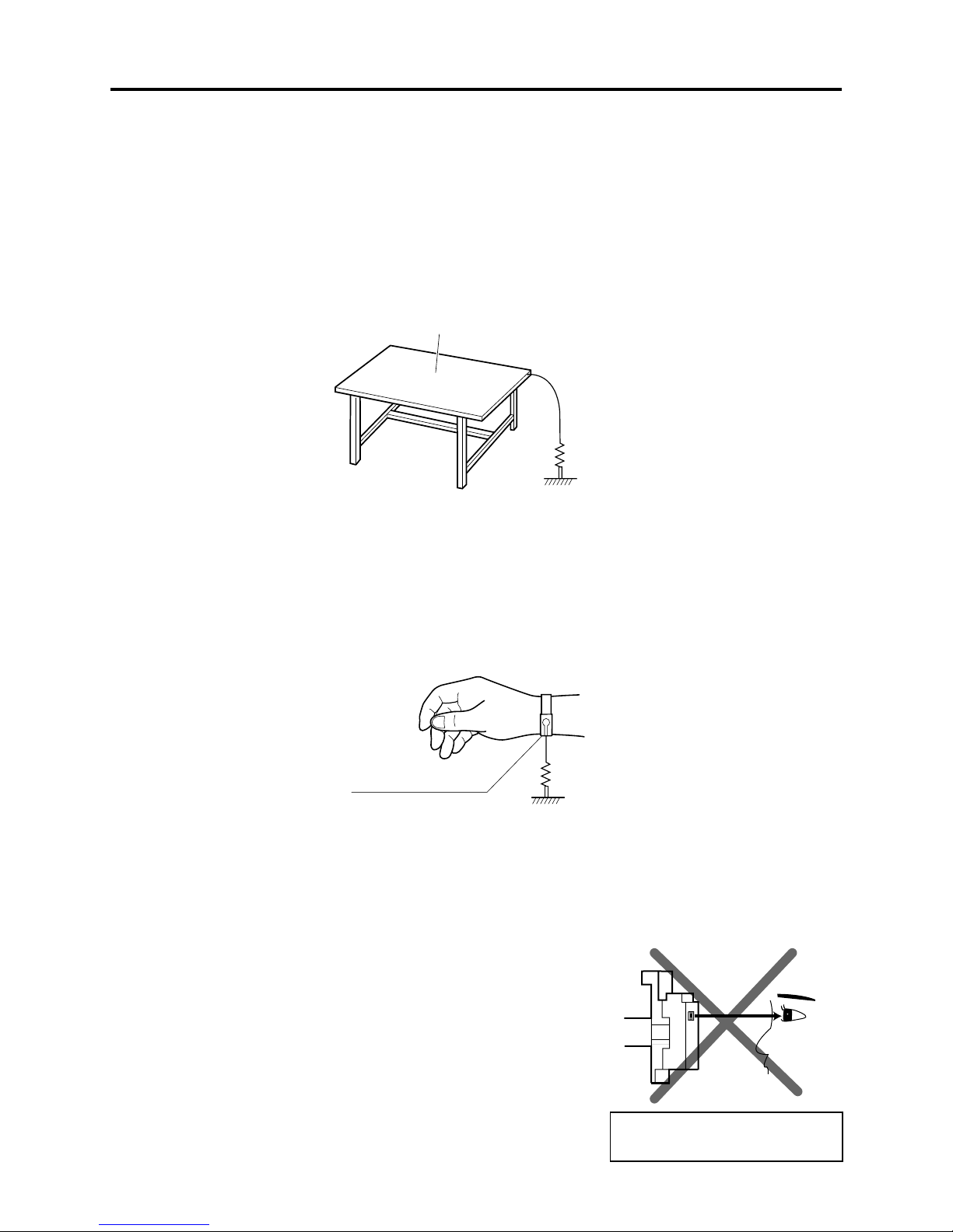
(1) Grounding work bench
Lay out an antistatic mat on work bench, and then use the ground plate to ground the work bench.
Antistatic mat
1M ohm
Ground
(2) Grounding human body
Use an antistatic wrist strap to discharge any static electricity charged on the body. Also, use a
tester for wrist strap to make sure that the wrist strap is working normally. Note, however, that
static electricity charged on clothes will not be discharged by wrist strap: Therefore do not allow
your clothes to touch the semiconductor components.
Antistatic wrist strap
1M ohm
1-3 Cautions When Handling DVD Drive
The optical pickup in DVD drive has a high precision structure: Be sure to observe the following
cautions.
1) Do not subject optical pickups to any severe vibrations or
impact during movement, installation or disassembly.
2) When performing repair work, do not perform disassembly any
further than that described in this manual.
3) Never turn the semi-variable resistors for adjustment in
optical pickup or DVD drive.
4) NEVER look into the objective lens in optical pickup or directly
view the laser light: You could lose your eyesight.
Do not directly look at laser light
from pickup.
1 - 2

Safety Precaution for Repair > Lead-Free Solder
1-4 Lead-Free Solder
The printed circuit board that uses lead-free solder is adopted. To protect the global environment,
use the recommended lead-free solder also during servicing.
Read and observe the following before soldering:
Caution
ALWAYS wear protective goggles during soldering so that no solder smoke or scattered solder
enters the eye. Lead-free solder may scatter at high temperatures of 600°C.
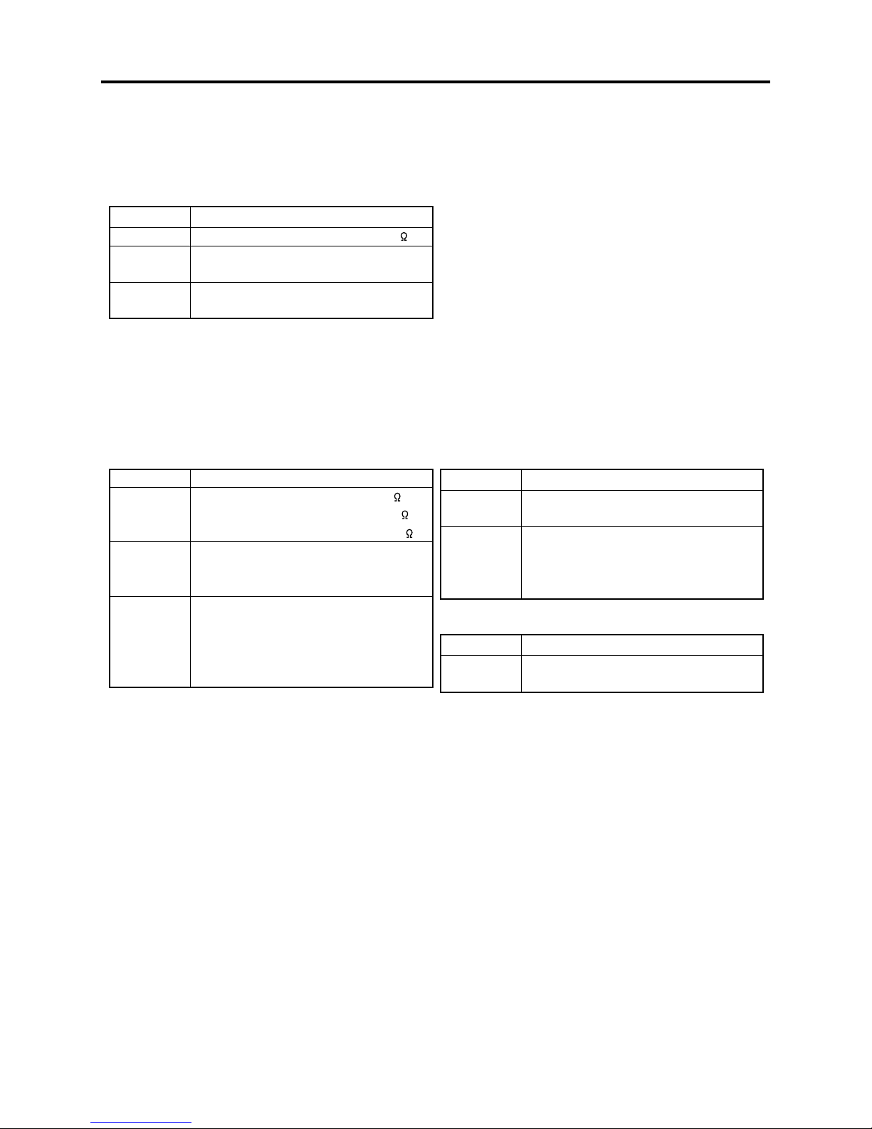
(1) Identifi cation of circuit boards that use lead-free solder
Pb
“ ” is stamped or noted with pattern letter on circuit boards that use lead-free solder.
A30C5
(2) Characteristics of lead-free solder
The components of lead-free solder used are as follows. The melting point of lead-free solder is
30-40°C higher than that of lead based solder:
Point to be soldered Composition of alloy (wt%)
For refl ow Solder paste: Sn-3Ag-0.5Cu
For dip Bar solder: Sn-0.6Cu
Melting temperature: Approx. 220°C
(3) Lead-free solder for servicing
Use the following lead-free solder for servicing:
Recommended lead-free solder and composition of alloy (wt%): Sn-3.0Ag-0.5Cu or equivalent
Information:
For composition of alloy, Sn is tin; Ag is silver; Cu is copper; Bi is bismuth; Pb is lead.
(4) Soldering iron for servicing
The temperature of soldering iron tip must be adjusted according to the points to be soldered: Use
an antistatic soldering iron with thermal control function.
When removing components, take care not to damage any surrounding component or pattern. When
attaching components, observe the heating time in the following table so that the components are
not destroyed by heat.
Tip temperatures for different soldering points:
oint to be soldered Tip temperature
Surface-mounted (chip) parts [other than
those shown below]
Surface-mounted (chip) parts [for DVD
cameras, cellular phones only]
Discrete parts 380 ± 30°C
Chassis, metal shield, etc. 420 ± 30°C
320 ± 30°C
[heating time: less than 5 seconds]
350 ± 10°C
[heating time: less than 3 seconds]
1 - 3

Safety Precaution for Repair > Lead-Free Solder
(5) Cautions when using lead based solder
It is recommended that you use lead-free solder when servicing, but it is also possible to service
using lead based solder. However, if lead based solder is used for servicing, take care with the
following:
1) Before using lead based solder, remove the lead-free solder completely from the point to be
soldered.
2) For additional soldering for repair, set the soldering iron tip temperature for lead-free solder,
mix lead based solder and lead-free solder suffi ciently. Do not perform any repair using the
bare soldering iron tip without adding solder, since it will cause secondary failure due to lack of
strength.
1 - 4
Safety Precaution for Repair > Notes When Using Service Manual
1-5 Notes When Using Service Manual
(1) Value units used in parts list
Certain symbols are indicated as shown below for value units of resistors, capacitors and coils in
parts list. When you read them, note the following regular indications:
Parts Indication in list Regular indication
Resistor KOHM ..........................................k
Capacitor UF ................................................. μF
PF ..................................................pF
Coil UH ................................................μH
MH ................................................ mH
(2) Values in schematic diagrams
The values, dielectric strength (power capacitance) and tolerances of the resistors (excluding
variable resistors) and capacitors are indicated in the schematic diagrams using abbreviations.
Certain symbols are indicated for value units: When you read them note the regular indications in
tables below:
[Resistors] [Capacitors]
Item Indication
Value No indication ................................
K .................................................... k
M ................................................... M
Tolerance No indication ................................ ±5%
(All tolerances other than ±5% are
indicated in schematic diagrams)
Power
capacitance
No indication ................................ 1/8W
(1/16 W for leadless resistors with no
indication)
All capacitances other than the above
are indicated in schematic diagrams.
Item Indication
Value No indication ................................ μF
Dielectric
strength
[Coils]
Item Indication
Value μ .................................................... μH
(3) Identifying sides A/B in circuit board diagrams
1) Board with pattern on one side only and parts on both sides:
Side A: Shows discrete parts.
Side B: Shows leadless parts, viewed from the pattern side.
Board with patterns and parts on both sides:
2)
Sides A and B are identifi ed without any predetermined rules.
P .................................................... pF
No indication ............................... 50V
(All dielectric strengths other than
50 V are indicated in schematic
diagrams)
m ................................................... mH
1 - 5

Safety Precaution for Repair > Notes When Using Service Manual
(4) Indicating model names
The indication of models is defi ned as follows:
1) The common parts of model names are omitted.
Example: When indicating VM-D975LA and VM-D875LA:
VM-D975LA/D875LA, D975LA/D875LA
2) If there is no difference in models going to different destinations, the indication of destination is
omitted.
Example: When indicating DZ-MV350E(AU) and DZ-MV350E(SW): DZ-MV350E
(5) Differences in parts between schematic and circuit board diagrams
If some parts are different between models, asterisks “*” are attached to the circuit numbers. Check
the parts difference tables in diagrams or parts location search system for details.
1 - 6
2
General Description
2-1 Overview
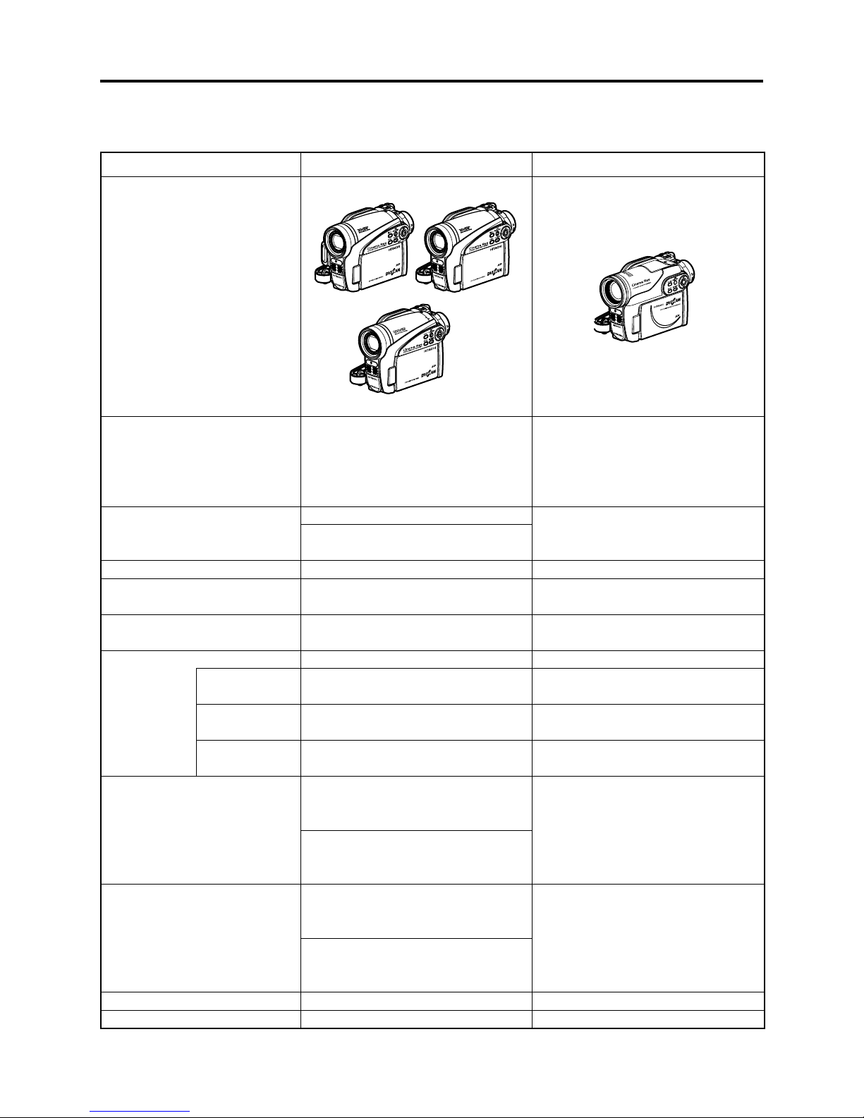
The DZ-GX5080A/GX5020A/GX5000A DVD video camera/recorders incorporate a CCD image sensor
with a total of approx. 680,000 pixels: HDD is not mounted.
The compatible recording/playback media are equivalent to those of conventional models as shown
in Table 2-1-1.
Table 2-1-2 shows the differences between DZ-GX5080A, DZ-GX5020A and DZ-GX5000A.
Table 2-1-1 Usable Recording/Playback Media on DZ-GX5080A/GX5020A/GX5000A
Media Movie Still
8cm DVD-RAM
8cm DVD-RW
8cm +RW
SD memory card Non-compatibility Recording/Playback possible
Table 2-1-2 Differences between DZ-GX5080A, DZ-GX5020A and DZ-GX5000A
Specifi cation/
Function
Optical Zoom 30x 25x
LED Light Provided Not provided
PC Connection Terminal Provided Not provided
Weight approx. 425g approx. 420g
Software CD-ROM of
accessory
PC Connection Cable of
accessory
Recording/Playback possible
DZ-GX5080A DZ-GX5020A DZ-GX5000A
Provided Not provided
Provided Not provided
Recording/Playback possible
Non-compatibility8cm DVD-R
2 - 1

General Description > Overview
2-1-1 Servicing method
Refer to the following table and perform the designated, appropriate servicing. Any changes that
occur in the service method will be published using service bulletin, etc.
Do not perform any servicing other than that described in this manual.
Table 2-1-3 Servicing method
Parts Name
(a) DVD Drive Unit Unit replacement
(b) Lens Unit Unit replacement
(c) EVF Unit Unit replacement
(d) LCD Unit Unit replacement or
(e) AVJ2-L Circuit Board Component replacement Not provided
(e) AVJ3-L Circuit Board Not provided Component replacement
(f) FRT2-L Circuit Board Component replacement Not provided
(f) FRT3-L Circuit Board Not provided Component replacement
(g) GSL2-L Circuit Board Component replacement Not provided
(g) GSL3-L Circuit Board Not provided Component replacement
(h) LMF2-L Circuit Board Component replacement Not provided
(h) LMF3-L Circuit Board Not provided Component replacement
(i) MAN Circuit Board Component replacement or circuit board replacement
(j) SDL Circuit Board Circuit board replacement
DZ-GX5080A DZ-GX5020A DZ-GX5000A
Servicing method
(a)
(b)
(f)
(e)
(d)
Fig. 2-1-1 Name of the circuit board/unit
(h)
(g)
(c)
(i)
(j)
2 - 2
General Description > Features / Specifi cations
2-2 Features
LED Light
The DZ-GX5080A incorporates an LED light that uses two highly luminous and long-life white
light-emitting diodes (LED). This LED light can also be used when recording a movie: Use the
button to turn the LED light on and off. The LED light allows you to record a subject in dark places
up to 1.5 m (4.9 feet) away.
SLEEP/RESTART button:
Pressing the SLEEP button in the recording pause status will shift the DVD video camera/recorder
to the SLEEP mode, in which the recording pause status is held using a minimum electric power.
FINALIZE button:
Simply pressing this button will fi nalize the recorded DVD-RW, DVD-R and +RW.
16:9 wide LCD monitor:
A 16:9 wide lCD monitor that corresponds to the wide-screen mode is mounted.
Images in viewfi nder are also displayed in wide-screen mode.
Capturing still:
During movie playback, a desired scene can be recorded on SD memory card as a still.
2-3 Specifi cations
Item Specifi cations
CCD Image Sensor 1/6-inch interlaced
Total number of pixels Approx. 680,000
Number of
effective pixels
Lens DZ-GX5080A
DZ-GX5020A
DZ-GX5000A F2.0 – 3.3, f= 1/16” – 2-5/16” (2.3 – 58 mm)
Filter diameter/Thread pitch 1-5/16” (34 mm) / 0.5mm
Focus Auto/Manual
Zoom DZ-GX5080A Optical 30×, 120× – 1500× with digital zoom added
DZ-GX5020A
DZ-GX5000A Optical 25×, 100× – 1200× with digital zoom added
Required minimum illumination 0.3 lx in Low light mode
Viewfi nder 0.2-inch color (equivalent to approx. 200,000 pixels)
LCD monitor 2.7-inch color TFT (approx. 120,000 pixels)
Image Stabilizer Electronic Type
Shutter speed 1/4 - 1/4000 second (movie)
Self-timer recording Still recording only
Recording mode Movie with sound (DVD-RAM/DVD-RW/DVD-R/+RW)
Maximum time
of recordable
video
DVD-RAM/DVD-RW/DVD-R/
+RW (per side)
Movie: Approx. 340,000
Still: Approx. 340,000
F2.0 – 4.1, f= 1/16” – 2-11/16” (2.3 – 69 mm)
(120× for still)
(100× for still)
Still (DVD-RAM/SD memory card)
XTRA mode: Approx. 18 min.
FINE mode: Approx. 30 min.
STD mode: Approx. 60 min.
2 - 3
General Description > Specifi cations
Item Specifi cations
Maximum
DVD-RAM (per side) Approx. 999
number of
recordable
SD memory Card (32MB) Approx. 180 (in FINE mode)
photos
Recording
format
DVD-RAM/DVD-RW (VR mode) Movie: Conforming to DVD video recording (DVD-VR)
format
Sound: Dolby Digital
Still (DVD-RAM only):
Simultaneous recording, conforming to DVD video
recording (DVD-VR) format (720 × 480 pixels) and
JPEG (640 × 480 pixels).
DVD-RW (VF mode) /DVD-R Movie: Conforming to DVD video format
Sound: Dolby Digital
+RW Movie: DVD+RW video format
Sound: Dolby Digital
Card Still: Conforming to JPEG
(640 × 480 pixels) format
Audio playback format Dolby Digital, MPEG Audio layer 2, Linear PCM (LPCM)
Recording media 8 cm DVD-RAM (conforming to DVD-RAM Ver. 2.1)
8 cm DVD-RW (conforming to DVD-RW for General
Ver. 1.1, 2 × speed)
8 cm DVD-R (conforming to DVD-R for General Ver. 2.0)
8 cm +RW (conforming to +RW Ver. 1.2)
SD memory card
Jacks DZ-GX5080A Video/audio output ×1
PC connection terminal (connected to PC USB port) ×1
DZ-GX5020A Video/audio output ×1
DZ-GX5000A
Battery system Lithium-ion
Power consumption
Approx. 3.2 W (DVD-RAM used, FINE mode)
(when recording with LCD
monitor off )
Dimensions
Approx. 2-1/2" × 3-9/16" × 5-3/16" (63 × 91 × 132 mm)
(W × H × D, excluding
projections)
Operating temperature (humidity) 32 - 104°F (0 - 40°C) (less than 80%)
32 - 86°F (0 - 30°C) when connected to PC
Storage temperature -4 - 104°F (-20 - 60°C)
Weight
(without battery and disc)
DZ-GX5080A Approx. 425 g
DZ-GX5020A Approx. 420 g
DZ-GX5000A
Total weight when recording DZ-GX5080A Approx. 480 g
DZ-GX5020A Approx. 475 g
DZ-GX5000A
(*1)
(*2)
*1: The number may decrease when videos are recorded on DVD-RAM, depending on the amount of
recorded data.
*2: May vary depending on the image quality.
2 - 4
General Description > Specifi cations
Item Specifi cations
Provided accessories AC adapter/charger (DZ-ACS3)
Battery (DZ-BP07PW)
AV/S output cable
Lens cap
Lens cap string
Shoulder strap
Power cable
DC power cord
Software CD-ROM
[not provided with DZ-GX5020A/GX5000A]
PC connection cable
[not provided with DZ-GX5020A/GX5000A]
Disc cleaning cloth
Specifi cations are subject to change without notice for the purpose of improvement.
Specifi cations of DZ-ACS3 AC Adapter/Charger
Power supply 100 - 240 V AC,
50/60 Hz
Input capacity 22 VA (at 100 V)
DC output (max.) 7.9 V, 1.4 A
Charge output 8.4 V, 0.65A
Weight 100 g
External dimensions
(W × H × D)
Ambient temperature for
operation
Allowable relative humidity 20 - 80%
61 × 32 × 91 mm
32 - 104°F (0 - 40°C)
2 - 5
General Description > Major Differences from Previous Models
2-4 Major Differences from Previous Models
Item DZ-GX5080A/GX5020A/GX5000A DZ-BX37A/BX35A
Dimensions (W × H × D) and
shape
Recording media
Internal LED light
Internal fl ash
Viewfi nder
LCD monitor
CCD image sensor
Total number of
pixels
Number of
pixels for Movie
Number of
pixels for still
Lens
Zoom
Filter diameter / Thread pitch
Required minimum illumination
Approx. 2-1/2" × 3-9/16" × 5-3/16" Approx. 1-7/8" × 3-1/2" × 5-3/16"
DZ-GX5080A DZ-GX5020A
DZ-GX5000A
8cm DVD-RAM
8cm DVD-RW
8cm DVD-R
8cm +RW
SD memory card
DZ-GX5080A: Provided
DZ-GX5020A/GX5000A:
Not provided
Not provided ←
0.2-inch color (equivalent to approx.
200,000 pixels, with 16:9 mode)
16:9, 2.7-inch color TFT
(approx. 120,000 pixels)
1/6-inch interlaced ←
Approx. 680,000 pixels
Approx. 340,000 pixels
Approx. 340,000 pixels
DZ-GX5080A/GX5020A:
F2.0 - 4.1
f=1/16" - 2-11/16" (2.3 - 69 mm)
DZ-GX5000A:
F2.0 - 3.3
f=1/16" - 2-5/16" (2.3 - 58 mm)
DZ-GX5080A/GX5020A:
Optical 30x, 120x - 1,500x with
digital zoom added (120x for still)
DZ-GX5000A:
Optical 25x, 100x - 1,200x with
digital zoom added (100x for still)
1-5/16" (34 mm) / 0.5 mm ←
0.3 lx (Low light mode) ←
Not provided
F1.8 - 3.2
f=1/16" - 2-3/16" (2.2 - 55 mm)
Optical 25x, 100x - 1,200x with
digital zoom added (100x for still)
←
: Same as on left
$:"8!"8!
←
←
←
←
←
←
2 - 6
General Description > Major Differences from Previous Models
Item DZ-GX5080A/GX5020A/GX5000A DZ-BX37A/BX35A
Power consumption (DVD-RAM
used, FINE mode)
Weight
Maximum
time of
recordable
video (per side)
Number of
pixels for
video(MPEG2)
Audio recording format Dolby Digital ←
Audio playback format
Maximum
number of
recordable
stills
Number of pixels for JPEG still
during camera recording
AV/S input function Not provided ←
Assist light function
EIS function Provided (Movie mode only) ←
LCD/EVF brightness setting
function
EVF display on/off function Provided ←
16:9 squeeze record mode
Disc protect
Accessory Shoe Not provided ←
AV output/input jack Provided (Output only) ←
External Microphone jack Not provided ←
PC connection terminal
Sleep/Restart button Provided ←
Select button Provided ←
Disc navigation button Provided ←
Menu button Provided ←
Stop/Exit button Provided ←
Full auto button Provided Not provided
Focus button Provided ←
Exposure button Provided ←
BLC button Provided ←
Display button Provided ←
Quick Menu button Provided Not provided
XTRA
FINE
STD Approx. 60 min/Fix: Approx. 3 Mbps ←
XTRA/
FINE
STD 352 × 480 pixels ←
DVD-RAM
(FINE)
SD memory
cord (32MB)
Approx. 3.2W
DZ-GX5080A: Approx. 425g
DZ-GX5020A/GX5000A:
Approx. 420g
Approx. 18 min/
Variable: Approx. 3 - 10 Mbps
Approx. 30 min/Fix: Approx. 6 Mbp
720 × 480 pixels
Dolby Digital, MPEG Audio layer 2,
Linear PCM (LPCM)
Approx. 999
FINE: Approx. 180 ←
NORM: Approx. 240 ←
ECO: Approx. 370 ←
640×480 pixels
Provided
(When Low Light mode is selected)
Provided
Provided
[Except for DVD-RW(VF mode)/
DVD-R/ +RW using, STD mode]
Software disc-protect
[DVD-RAM/DVD-RW(VR mode)]
DZ-GX5080A: Provided DZ-BX37A: Provided
DZ-GX5020A/ GX5000A:
Not Provided
Approx. 420g
DZ-BX35A: Not Provided
←
←
←
←
←
←
←
←
←
←
←
2 - 7

General Description > Major Differences from Previous Models
Item DZ-GX5080A/GX5020A/GX5000A DZ-BX37A/BX35A
Finalize button Provided ←
+ / - button Not provided (the zoom lever is used
in common to adjust the volume;
the cursor keys are used for camera
adjustment)
Accessories AC adapter/
charger
Battery Provide (DZ-BP07PW) ←
infrared remote
control
Single-sided
8cm DVD-R disc
PC connection
cable
Software
CD-ROM
*1: Windows® 2000 Professional SP3 or higher.
Windows® XP Home Edition or higher
Windows® XP Professional Edition or higher
See the following Websites to fi nd out whether the provided software can be used on
Windows Vista:
URL:http://www.pixela.co.jp/oem/hitachi/e/index.html
URL: http://dvdcam-pc.support.hitachi.ca/
*2: Mac OS X v10.3.9, v10.4.2-v10.4.8
*3: Mac OS X v10.2.8/v10.3.4-v10.3.9/v10.4.1-v10.4.3
Provided (DZ-ACS3)
Not provided
Not provided
DZ-GX5080A: Provided DZ-BX37A: Provided
DZ-GX5020A/GX5000A:
Not Provided
DZ-GX5080A: Provided
For Windows(*1):
ImageMixer 3
For Macintosh(*2):
ImageMixer 3 Mac Edition for
DVDCAM
DZ-GX5020A/GX5000A:
Not Provided
Provided
←
←
←
DZ-BX35A: Not Provided
DZ-BX37A: Provided
For Windows(*1):
ImageMixer 3
For Macintosh(*3):
Pixe VRF Browser EX,
ImageMixer VCD/DVD2
DZ-BX35A: Not Provided
2 - 8

General Description > Compatibility of Recorded DVD and Corresponding Recording Media
2-5 Compatibility of Recorded DVD and Corresponding
Recording Media
2-5-1 Compatibility of Recorded Discs
(1) DVD-RAM
1) DVD-RAM recorded or edited on DZ-GX5080A/GX5020A/GX5000A:
The DVD-RAM can be recorded, edited and played
recorders.
2) DVD-RAM recorded or edited on other Hitachi DVD video camera/recorders:
The DVD-RAM can be recorded, edited and played
DZ-GX5080A/GX5020A/GX5000A. However, scene memos recorded on the Disc Navigation
function of DZ-MV100A cannot be played or edited on another model.
*1: If disc-protect is set, it must be released in order to record or edit on the disc. However, since the
DZ-MV100A and DZ-MV200A series models use a different disc-protect method, disc-protect that was
set on other models cannot be released on them.
(2) DVD-R
1) DVD-R recorded edited on DZ-GX5080A/GX5020A/GX5000A:
The DVD-R can be played back on other Hitachi DVD video camera/recorders
fi nalized. However, be sure not to record or fi nalize a DVD-R using other Hitachi DVD video
camera/recorders: Doing so will make the DVD-R unusable.
Also, do not insert a DVD-R not fi nalized into a DVD recorder, etc.
DVD-R unusable.
2) DVD-R recorded or edited on other Hitachi DVD video camera/recorders
The DVD-R can be played back on DZ-GX5080A/GX5020A/GX5000A
However, be sure not to record or fi nalize the DVD-R using DZ-GX5080A/GX5020A/GX5000A :
Doing so will make the DVD-R unusable.
*2: Only for models that conform to DVD-R. See “Table 2-5-1 List of Compatible Recording Media” for the
models that conform.
*3: Except for DVD recorders, etc. whose instruction manuals state that “This model can play back a DVD-R
recorded on Hitachi DVD video camera/recorders but not fi nalized.
*4: Loading a DVD-R/DVD-RW(VF mode) will automatically start the Disc Navigation function.
(*1)
on other Hitachi DVD video camera/
(*1)
on
(*2)
without being
(*3)
: Inserting it may make the
(*2)
:
(*4)
without being fi nalized.
(3) DVD-RW (VR mode)
1) DVD-RW(VR) recorded or edited on DZ-GX5080A/GX5020A/GX5000A:
The DVD-RW(VR) can be recorded, edited and played back on other Hitachi DVD video camera/
recorders
2) DVD-RW(VR) recorded or edited on other Hitachi DVD video camera/recorders
The DVD-RW(VR) can be recorded, edited and played back on DZ-GX5080A/GX5020A/ GX5000A
in the same way.
*5: Only for models that conform to DVD-RW. See “Table 2-5-1 List of Compatible Recording Media” for the
models that conform.
(*5)
.
2 - 9
(*5)
:

General Description > Compatibility of Recorded DVD and Corresponding Recording Media
(4) DVD-RW (VF mode)
1) DVD-RW(VF) recorded or edited on DZ-GX5080A/GX5020A/GX5000A:
The DVD-RW(VF) can be played back on other Hitachi DVD video camera/recorders
(*5)
without
being fi nalized. However, be sure not to record or fi nalize the DVD-RW(VF) using other Hitachi
DVD video camera/recorders: Doing so will make the DVD-RW(VF) unusable.
Also, do not insert a DVD-RW not fi nalized into a DVD recorder, etc.
(*6)
: Inserting it may make
the DVD-RW unusable.
(*5)
2) DVD-RW(VF) recorded or edited on other Hitachi DVD video camera/recorders
The DVD-RW(VF) can be played back on DZ-GX5080A/GX5020A/GX5000A
:
(*4)
without being
fi nalized. However, be sure not to record or fi nalize the DVD-RW using DZ-GX5080A/GX5020A/
GX5000A: Doing so will make the DVD-RW unusable.
*4: Loading a DVD-R/DVD-RW(VF mode) will automatically start the Disc Navigation function.
*5: Only for models that conform to DVD-RW. See “Table 2-5-1 List of Compatible Recording Media” for the
models that conform.
*6: Except for DVD recorders, etc. whose instruction manuals state that “This model can play back a DVD-
RW(VF mode) recorded on Hitachi DVD video camera/recorders but not fi nalized.
(5) +RW
1) +RW recorded or edited on DZ-GX5080A/GX5020A/GX5000A:
The +RW can be recorded, edited and played
2) +RW recorded or edited on other Hitachi DVD video camera/recorders
The +RW can be recorded, edited and played
*7: Only for models that conform to +RW. See “Table 2-5-1 List of Compatible Recording Media” for the
models that conform.
compatible with recording or playback of +RW.
(*7)
on other Hitachi DVD video camera/recorders.
(*7)
:
(*7)
on DZ-GX5080A/GX5020A/GX5000A.
2 - 10

General Description > Compatibility of Recorded DVD and Corresponding Recording Media
2-5-2 Corresponding Recording Media
M: Movie
S: Still
RP: Recording/Playback possible
Table 2-5-1 List of Compatible Recording Media
Model HDD
DZ-HS303A/ HS300A
DZ-GX5080A/ GX5020A/
GX5000A
DZ-GX3300A/ GX3200A/
GX3100A/ BX37A/ BX35A
DZ-GX20MA/ MV780MA/
MV750MA/ BX31A
DZ-GX20A/ MV780A/
MV730A
DZ-MV580A/ MV550A
DZ-MV380A/ MV350A
DZ-MV270A/ MV230A/
MV200A
DZ-MV100A N
M: RP
S:N
N
DVD-
RAM
M: RP
S: P
M: RP
S: RP
DVD-R DVD-RW +RW Note
M: RP
S: N
8 cm disc Card
M: RP
M: RP
S: N
N
S: N
P: Only playback possible
N: Non-compatibility
No holder/
cartridge/
caddy case
needed
N
Holder
needed
Cartridge/
caddy case
needed
memory
SD
Multi-
media
card
M: N
S: RP
NN
card
N
M: N
S: RP
2 - 11
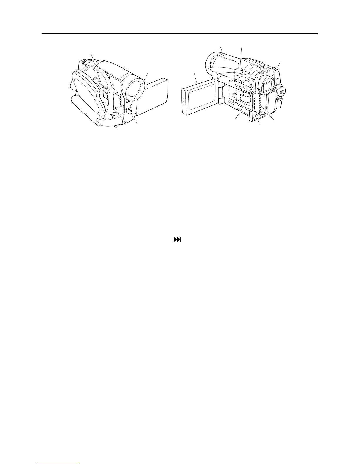
General Description > Names of Parts
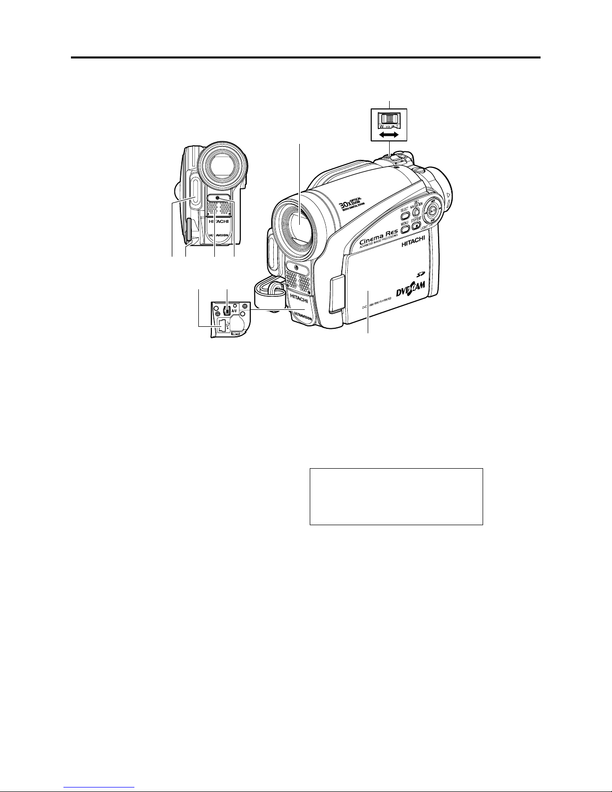
2-6 Names of Parts
,%$LIGHTFOR$:'8!ONLY
,ENSCAPSTRINGATTACHMENTHOLE
3TEREOMICROPHONE
4AKECARETHATTHEMICROPHONEISNOTBLOCKED
BYAHANDETCDURINGRECORDING
2ECORDINGINDICATOR
4HEREDINDICATORWILLLIGHTDURINGRECORDING
/PTICAL§ZOOMLENS
FOR$:'8!ONLY
/PTICAL§ZOOMLENS
FOR$:'8!'8!ONLY
)NSIDETHECOVER
:OOMLEVER
4OADJUSTTHEZOOMORVOLUME
0#CONNECTIONTERMINAL4/0#FOR$:
'8!ONLY
!6OUTPUTJACK
7IDESCREENCOLORLIQUIDCRYSTALDISPLAY
INSIDE
!LTHOUGHTHEEXTERNALAPPEARANCESOF$:
'8!$:'8!AND$:'8!ARE
DIF FERENTTHEMETHODOFOPERATINGTHESE
MODELSISIDENTICAL$:'8!ILLUSTRATIONS
AREUSEDINTHISMANUAL
2 - 12
General Description > Names of Parts
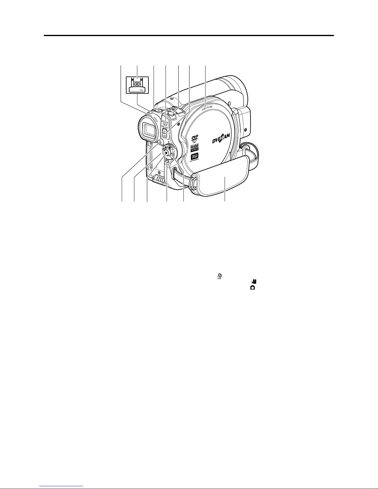
6IEWFINDER
$IOPTERCONTROL
4OADJUSTTHEFOCUSOFIMAGEAPPEARINGINTHE
VIEWFINDER0ULLOUTTHEVIEWFINDER
3,%%02%34!24BUTTON
4OSWITCHTHESLEEPRESTARTSTATUSBETWEEN
/.AND/&&
!##%330#INDICATOR
FOR$:'8!ONLY
!##%33INDICATORFOR$:'8!
'8!ONLY
7ILLBLINKORLIGHTWHENTHEDISCIN$6$
VIDEOCAMERARECORDERISACCESSEDWRITEOR
READISEXECUTEDORTHE$6$VIDEOCAMERA
RECORDERISCONNECTEDTO0#
"!44%29%*%#4BUTTON
0RESSTHISBUTTONWHENREMOVINGTHEBATTERY
"ATTERYATTACHMENTPLATFORM
2ECORDBUTTON2%#
,/#+SWITCH
)TISRECOMMENDEDTHATYOUSETTHE,/#+
SWITCHTO
THEPOWERSWITCHINTHE h
ACCIDENTALLYMOVINGTO h
0OWERSWITCH
(ANDSTRAP
TOTHEUPPERPOSITIONTOPREVENT
vPOSITIONFROM
v
0(/4/BUTTON
$)3#%*%#4BUTTON
0RESSDOWNANDRELEASETHISBUTTONTOOPEN
THECOVEROFDISCINSERTIONBLOCK
$ISCINSERTIONBLOCK
2 - 13
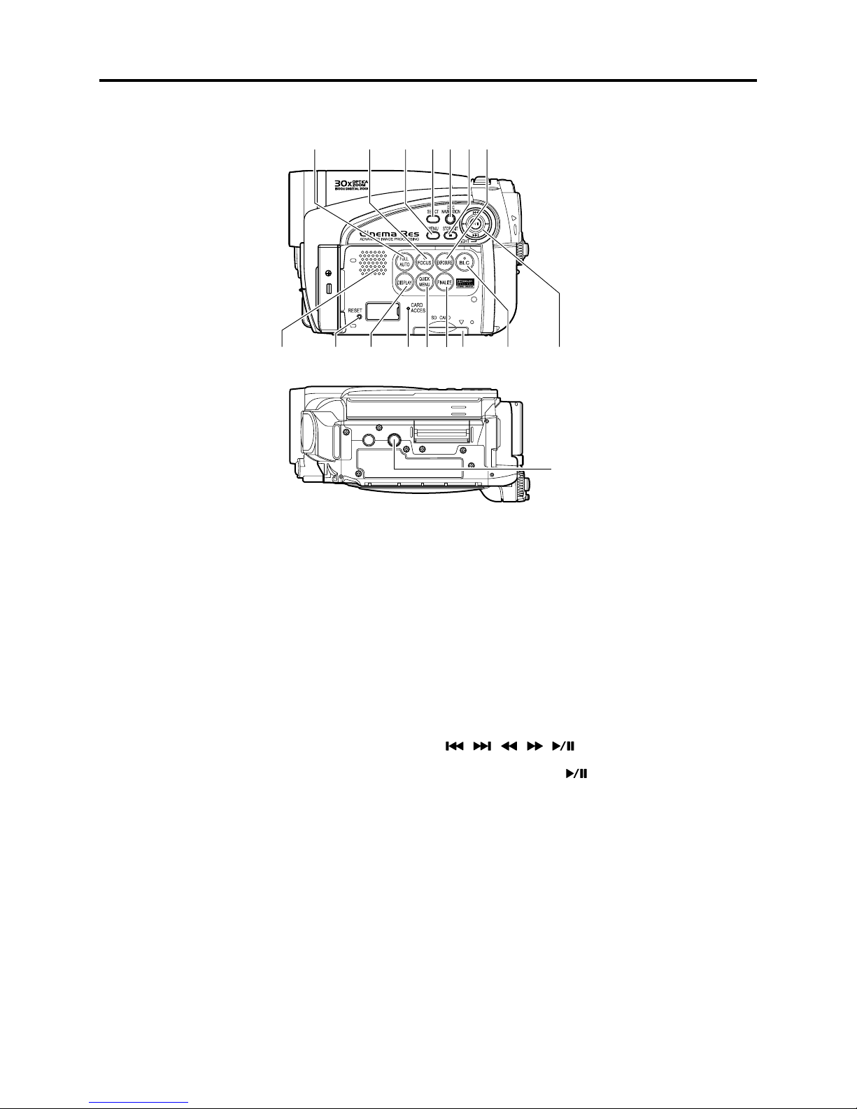
General Description > Names of Parts
&5,,!54/
4OSWITCHTHE$6$VIDEOCAMERARECORDERTO
FULLAUTOMATIC
&/#53BUTTON
4OSWITCHBETWEENMANUALFOCUSANDAUTO
FOCUS
-%.5BUTTON
0RESSTHISBUTTONTODISPLAYTHEMENUFOR
SETTINGCAMERAFUNCTIONSAND$ISC
.AVIGATION
3%,%#4BUTTON
$)3#.!6)'!4)/.BUTTON
34/0%8)4BUTTON
4OENDPLAYBACKORCANCELSETTINGOFMENU
%80/352%BUTTON
0RESSTHISBUTTONTOADJUSTTHEEXPOSURE
3PEAKER
2%3%4BUTTON
4ORESETALLSETTINGSTODEFAULTSSTATUSWHEN
THE$6$VIDEOCAMERARECORDERWAS
SHIPPEDFROMTHEFACTORY
$)30,!93CREENDISPLAYBUTTON
0RESSTHISBUTTONTODISPLAYTHEDETAILSOF
IMAGEBEINGPLAYEDBACKORCAMERASETTING
STATUSORSWITCHTHEDISPLAYOF F
#!2$!##%33INDICATOR
15)#+-%.5BUTTONS
4ODISPLAYONLYTHEFUNCTIONSTHATYOU
FREQUEENTLYUSESIMPLEMENUS
&).!,):%BUTTON
0RESSTHISBUTTONTOFINALIZETHERECORDED
$6$ 27$6$22 7
#ARDINSERTIONBLOCK
",#BACKLIGHTCOMPENSATIONBUTTON
0RESSTHISBUTTONWHENSUBJECTISBEING
LIGHTEDFROMREAR
BUTTONS
5SETHESEBUTTONSTOSELECTASCENEORMENUITEM
ANDTHENPRESSTHECENTER
SCENEORDESIGNATEANOPTIONFROMTHEMENU
4HESEBUTTONSARETOADJUSTEXPOSUREORFOCUSAND
SWITCHTHE,%$LIGHT$:'8!ONANDOF F
4RIPODTHREADEDHOLE
5SEDTOATTACHTHE$6$VIDEOCAMERA
RECORDERTOATRIPOD
TOPLAYBACKTHE
2 - 14

General Description > Names of Parts
Accessories
"ATTERYMODEL$:"007
0ORTABLEPOWERSUPPLYFORTHIS$6$VIDEO
CAMERARECORDER#HARGEITBEFOREUSE
0OWERCABLE
#ONNECTBETWEENHOUSEHOLD!#OUTLETAND
!#ADAPTERCHARGER
,ENSCAPANDLENSCAPSTRING
!TTACHTHELENSCAPWHENNOTRECORDINGTO
PROTECTTHELENS
!#ADAPTERCHARGERMODEL$:!#3
5SEDTOPOWERTHE$6$VIDEOCAMERA
RECORDERFROM!#OUTLETORCHARGEBATTERY
!63OUTPUTCABLE
5SEDWHENVIEWINGTHEPICTUREPLAYEDBACK
ONTHE$6$VIDEOCAMERARECORDERON46
SCREENOROUTPUTVIDEOTOANOTHERVIDEO
DEVICE
3OFTWARE#$2/-
&OR$:'8!ONLY
5SETHIS#$2/-WHENCONNECTINGTHE
$6$VIDEOCAMERARECORDERTO0#
$#POWERCORD
7HENPOWERINGTHE$6$VIDEOCAMERA
RECORDERFROMHOUSEHOLD!#OUTLETUSE
THISCORDTOCONNECTTHE$6$VIDEO
CAMERARECORDERAND!#ADAPTERCHARGER
3HOULDERSTRAP
!TTACHTOTHE$6$VIDEOCAMERARECORDER
TOHANGITFROMSHOULDER
0#CONNECTIONCABLE
&OR$:'8!ONLY
5SETHISCABLEWHENCONNECTINGTHE$6$
VIDEOCAMERARECORDERTO0#
$ISCCLEANINGCLOTH
!LWAYSUSETHISTOCLEANDISCS
2 - 15
General Description > List of Abbreviations and Terms for DVD Video Camera/Recorders
2-7 List of Abbreviations and Terms for DVD Video
Camera/Recorders
Index Abbreviation/Term Explanation
A AC3 See Dolby AC3.
C CPRM Content Protection for Recordable Media: Copyright protection function that is
suitable for online distribution of music.
CSP IC Chip Scale Package IC or Chip Size Package IC: This IC was made compact by
arranging pins under the package.
D DCF Design rule for Camera File system standard: This camera fi le system standard.
Dolby AC3 Audio coding format developed by Dolby Laboratories in U.S, also simply referred
as AC3 format: Supports 5-channel full-range sound and one channel for sub-woofer
sound playback.
Dolby Digital See Dolby AC3.
DPOF Digital Print Order Format: DPOF allows user to record print information along
with photos on storage media to facilitate printing of photos.
DVD Digital Versatile Disc. A huge amount of digital data for video (movie) and audio
can be recorded on this disc, whose size is the same as CD.
DVD-Audio One type of DVD standard disc, on which high-quality audio can be recorded
DVD-R One type of DVD standard disc, to which writing once is possible (recordable type)
DVD-RAM One type of DVD standard disc, to which writing up to 100,000 times is possible
DVD-ROM One type of DVD standard disc, to which data for computer can be recorded
DVD-RW One type of DVD standard disc, to which writing up to 1000 times is possible
DVD-Video One type of DVD standard disc, on which high-quality video and audio can be
recorded
DVD Video
Format
DVD Video Video recording/playback standard that applies to DVD-RAM and DVD-RW: This
Recording Format allows versatile editing functions, differing from the DVD Video Format.
DVD-VR Format See DVD Video Recording Format.
DVD+RW
Video Format
E Exif Exchangeable image fi le format. File format used for recording photos on digital
F FireWire See IEEE1394.
FNR Frame Noise Reducer: This function or circuit automatically recognizes noise that
I IEEE1394 Also referred to as FireWire or i-LINK: Standard for serial interface that connects
Interlaced CCD This CCD scans one image twice (scans roughly once and interpolates between fi rst
i-LINK See IEEE1394.
J JPEG Joint Photographic Expert Group: International standard format for compressing
L LCD Liquid Crystal Display. LCD formats include STN and TFT.
LPCM Linear Pulse Code Modulation. Also referred to as linear PCM. LPCM is a format
Video recording/playback standard that applies to DVD-Video, DVD-R and DVD-
RW
Video recording/playback format for +RW was developed by DVD industry
organization “DVD+RW Alliance”, which is different from the DVD Forum.
cameras.
randomly occurs between frames and removes it.
PC and peripheral devices
scanning lines the second time) and interlaces the images obtained by scanning
twice to create a one-image signal.
still images
that digitizes analog audio data during recording and converts it to analog data
during playback.
2 - 16
General Description > List of Abbreviations and Terms for DVD Video Camera/Recorders
Index Abbreviation/Term Explanation
M MMC See MultiMediaCard.
MPEG Motion Picture Experts Group: Standard related to compression of digital video
and audio. MPEG2 is a higher standard of MPEG and is applied to video (movie)
requiring higher quality.
MPEG Audio
Layer 2
MultiMediaCard Also referred to as MMC. Compact memory card, 32 mm long × 24 mm wide × 1.4
S SCSI Small Computer System Interface: A standard for connecting computer and
SDMI Secure Digital Music Initiative: This conference was established by hardware
SD Memory Card Formally named Secure Digital Memory Card. This compact memory card, 32
SecureMMC See Secure MultiMediaCard.
Secure Also referred to as SecureMMC. This compact memory card has multimedia card
MultiMediaCard specifi cations, to which an advanced copyright protection function is added.
Software discProtect
STN LCD Super-Twisted Nematic Liquid Crystal Display: This type of color LCD is inferior to
T TFT LCD Thin Film Transistor Liquid Crystal Display: This type of color LCD features clear
U UDF Universal Disc Format, which is a fi le format of recordable disc defi ned by OSTA.
USB Universal Serial Bus: Standard of serial interface that connects PC and peripheral
V VBR Stands for Variable Bit Rate: This format of coding audio and video varies the
Etc. +R Digital discs whose specifi cations are established and promulgated by “DVD+RW
+RW
One of three audio compression standards (layers 1-3) defi ned by MPEG
mm thick
peripheral devices. The number, First, Ultra, Wide, etc., prefi xed or suffi xed to
SCSI indicates the data transfer rate and connector specifi cations.
makers, the Recording Industry Association of America (RIAA) and music industry
companies, to protect copyrights of musical compositions.
mm long × 24 mm wide × 2.1 mm thick, is equipped with an advanced copyright
protection function.
This function writes the protect information to DVD-RAM disc to prevent accidental
erasure. Software Disc-Protect is included in DVD-RAM disc specifi cations defi ned
by DVD Forum.
TFT LCD in coloring, view angle, etc.
display, high contrast, wide view angle, etc.
The revision 2.01 UDF is used on DVD video camera/recorder.
devices. Two versions - USB1.1 and USB2.0, with different data transfer rates -
exist at present.
amount of data depending on the subject image.
Alliance”, which is an industrial group different from “DVD Forum”. +R is
recordable, and +RW is rewritable. They are also referred to as DVD+R and
DVD+RW.
2 - 17

3
Description of Operation
3-1 Description of Structure
The DZ-GX5080A/GX5020A/GX5000A is produced based on the previous DZ-BX37A/BX35A.
Therefore the confi guration of components closely resembles that of DZ-BX37A/BX35A.
(1) Major differences from DZ-BX37A/BX35A
1) The shape, design and color at the top of product and on the left (LCD monitor side) are
different.
2) The lens unit is different.
(2) Major circuit boards /units in DZ-GX5080A/GX5020A/GX5000A
(a) DVD drive unit (DRG circuit board):
The DRG circuit board in unit incorporates the DVD drive circuit and the power supply
circuit of the entire DVD video camera/recorder.
(b) Lens unit:
Although the magnifi cation of zoom is different for DZ-GX5080A/GX5020A (30-power optical
zoom) and DZ-GX5000A (25-power optical zoom), the shape of lens unit is identical.
(c) EVF unit
(d) LCD unit (LCD circuit board):
The LCD circuit board in unit incorporates the LCD monitor drive and backlight drive
circuits.
(e) AVJ2-L/AVJ3-L circuit board:
Incorporates the AV output jack and PC connection terminal.
AVJ2-L is for DZ-GX5080A; AVJ3-L for DZ-GX5020A/GX5000A.
(f) FRT2-L/FRT3-L circuit board:
Incorporates the white balance (WB) sensor, internal microphone amp, etc.
The FRT2-L circuit board in DZ-GX5080A also has LED light circuit.
FRT2-L is for DZ-GX5080A; FRT3-L for DZ-GX5020A/GX5000A.
(g) GSL2-L/GSL3-L circuit board:
This circuit board connects the CCD image sensor to MAN circuit board. It incorporates an
EIS sensor, CCD drive IC, etc.
GSL2-L is for DZ-GX5080A; GSL3-L for DZ-GX5020A/GX5000A.
(h) LMF2-L/LMF3-L circuit board:
This circuit board connects the circuit board (incorporating a card slot) in L case to MAN
circuit board.
LMF2-L is for DZ-GX5080A; LMF3-L for DZ-GX5020A/GX5000A.
(i) MAN circuit board:
Incorporates the circuits that control the entire DVD video camera/recorder and the video/
audio signal processing circuits.
(j) SDL circuit board:
Incorporates an SD memory card slot. It also relays the MAN circuit board and LCD unit.
3 - 1
Description of Operation > Description of Structure / Description of Newly Adapted Technology
(a)
(e)
(f)
(b)
(d)
(h)
(g)
(c)
(i)
(j)
Fig. 3-1-1 Confi guration of circuit boards and their mounting locations
3-2 Description of Newly Adapted Technology
3-2-1 LED Light
The DZ-GX5080A incorporates an LED light that uses two highly luminous and long-life white
light-emitting diodes (LED), in place of the fl ash that is mounted in some conventional models.
The fl ash was effective only when recording stills, whereas the LED light can also be used when
(*1)
recording movies, and the assist light function
be used at the same time.
The LED light is turned on/off by pressing the
places up to 1.5 m (4.9 feet) away.
*1: Specify “Program AE: Low Light”, and turn the LCD monitor 180º in the open status so that it faces the
front (a subject): The LCD monitor will light white and become a light source.
that has been featured in conventional models can
button, allowing you to record a subject in dark
3 - 2
4
Troubleshooting
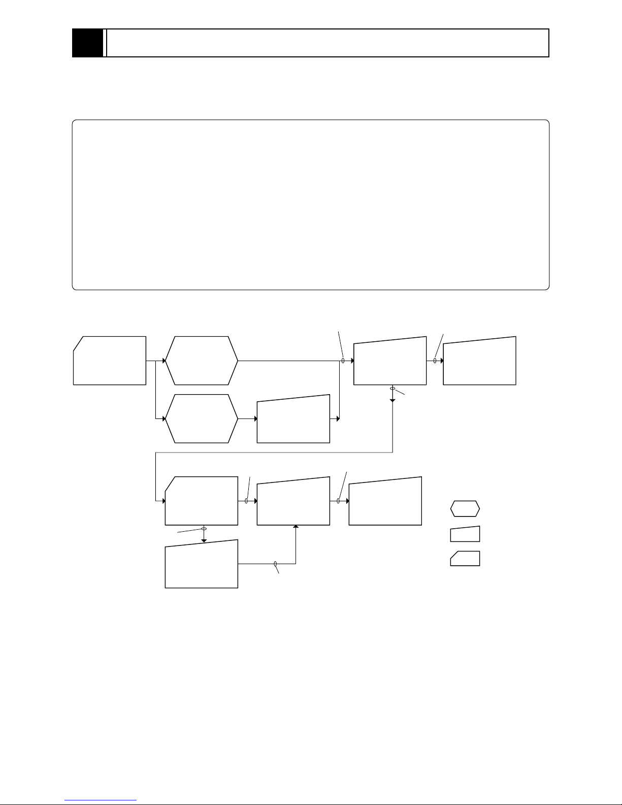
4-1 Procedure for Troubleshooting
Perform troubleshooting in the order shown in Fig. 4-1-1.
Note:
1) Before troubleshooting or servicing, be sure to obtain customer approval for the following:
a) The recorded contents on disc may be lost depending on the details and situation of fault
(defect).
b) The date/time and various settings, including video recording mode, designated by customer
after purchase, may be reset to the defaults before purchase (factory settings).
2) Perform “4-7-2 System reset procedure” after repair is completed: Note that system reset will
erase all error codes that will be necessary for troubleshooting.
3) Take notes of settings on received product in the Remarks and Memo columns, referring to “Table
4-7-1 List of items to be reset”: These notes will be necessary not only for reset, but for checking
any defects that occur under the particular setting conditions.
No improvement
Check
phenomenon
Updating
needed
*1: Messages and error codes will appear on LCD monitor or in viewfi nder.
No message
appears
Message
appears
Check firmware
versions
(section 4-4-1)
Update firmware
(section 4-4-2)
(*1)
(*1)
Messages and
Troubleshooting
(section 4-2)
Updating
unneeded
Tr o ub l e
Diagnosis
(section 4-5)
No improvement
after updating
No improvement
Display of Error
Codes and
Troubleshooting
(section 4-3)
Check
troubleshooting
with the factory
Error codes not included in
service manual appear
Check
troubleshooting
with the factory
No improvement
: Phenomenon
: Troubleshooting
: Check
( )
: Refer to section
Fig. 4-1-1
4 - 1

Troubleshooting > Messages and Troubleshooting
4-2 Messages and Troubleshooting
Some messages may appear on the LCD screen or in the viewfi nder during operation. If a message
appears, check the following, and then perform the appropriate action, according to the message
content:
1) Is the disc bottom/surface reversed when using a single-sided disc?
If so, reload the disc properly.
2) Is there any condensation on the lens or in the DVD drive unit of DVD video camera/recorder?
Condensation will occur when the DVD video camera/recorder is moved from a cold place to a warm place,
e.g. If condensation occurs, set the power switch to “OFF” with the disc loaded, and then leave the DVD
video camera/recorder in a dry place until condensation disappears (for 1-2 or more hours).
The messages divided using broken lines in the table can be displayed in sequence from the upper
row by pressing the button.
Message
Cannot combine scene. Appears if an attempt is made to
combine unconnected scenes: The
specifi cations state that combining of
only multiple scenes is possible.
Cannot combine scene of
multiple programs.
Create Playlist fi rst,
and then combine scenes.
Cannot combine.
Deselect PHOTO scenes.
Cannot combine.
Select multiple scenes.
Cannot delete scenes. Appears when user performed deletion
Cannot execute.
Change display
category to All.
Appears when combining the scenes in
different programs was attempted.
Appears if an attempt is made to
combine scenes when a photo was
selected: The specifi cation state that
combining of only video scenes is
possible.
Appears when combining one scene was
attempted.
at the upper limit of 999 scenes
registered.
Appears when combining or moving
scenes was instructed with “Category:
Movie or Still” specifi ed.
Cause/condition for
message to appear
(*1)
Troubleshooting
Stop trying to combine scenes, or
create a play list containing the
scenes to be combined, and combine
them on the play list.
When combining those scenes, fi rst
create a play list, and then combine
the scenes on it.
Select only video scenes, or stop
trying to combine scenes.
Select multiple scenes and then
combine them.
Combine divided scenes, and then
delete if necessary.
Specify “Category: All”, and then
operate the DVD video camera/
recorder again.
(*2)
*1: The DVD video recording format defi nes the maximum number of entry points as 999: Since one entry
point is allocated to one scene, the maximum number of scenes recordable on disc with the DVD video
camera/recorder is 999.
*2:
If recording is continued without editing, one scene will comprise one cell for each entry point.
When scenes are combined, only the number of entry points will decrease (only the entry point is deleted);
the number of cells will not decrease. Assume, for example, that the number of cells before
scenes are combined is 999, which is the upper limit defi ned by the DVD video recording format. If a
scene comprising one cell is divided at two points and the scene between the divided scenes needs to be
deleted, the cell must be further divided in order to delete. However, since the number of cells has reached
the upper limit in this case, the cell cannot be divided and the scene cannot be deleted.
4 - 2
 Loading...