

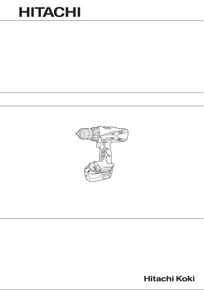
Cordless Combi Drill
DV 14DVC2 • DV 18DVC2
DV18DVC2
Read through carefully and understand these instructions before use.
Handling instructions
12
6
3
5
3
1
3
2
4
7
2
34
0
i
1
2
5
8
2
0
9
56
%
#
$
@
!
!
$
^
&
78
(
*
2
*
)
910
e
t
y
q
w
r
11 12
u
u
3
English
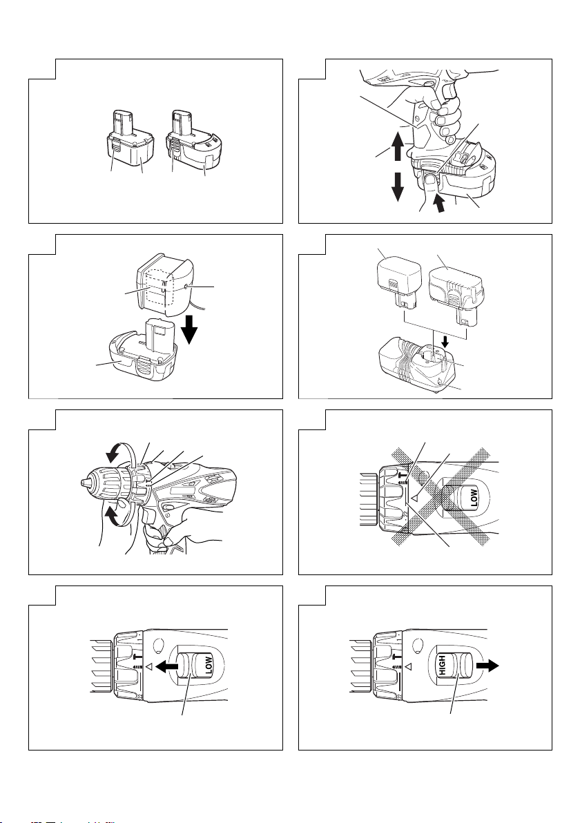
14.4 V Rechargeable battery
1
(For DV14DVC2)
18 V Rechargeable battery
2
(For DV18DVC2)
Latch
3
Pull out
4
Insert
5
Handle
6
Push
7
Insert
8
Pilot lamp
9
Hole for connecting the
0
rechargeable battery
Drill mark
!
Hammer marks
@
Clutch dial
#
Triangle mark
$
Weak
%
Strong
^
Line
&
Shift knob
*
Low speed
(
High speed
)
Ring
q
Sleeve
w
Tighten
e
Loosen
r
Trigger switch
t
Selector button
y
u
and marks
Battery set lamp
i
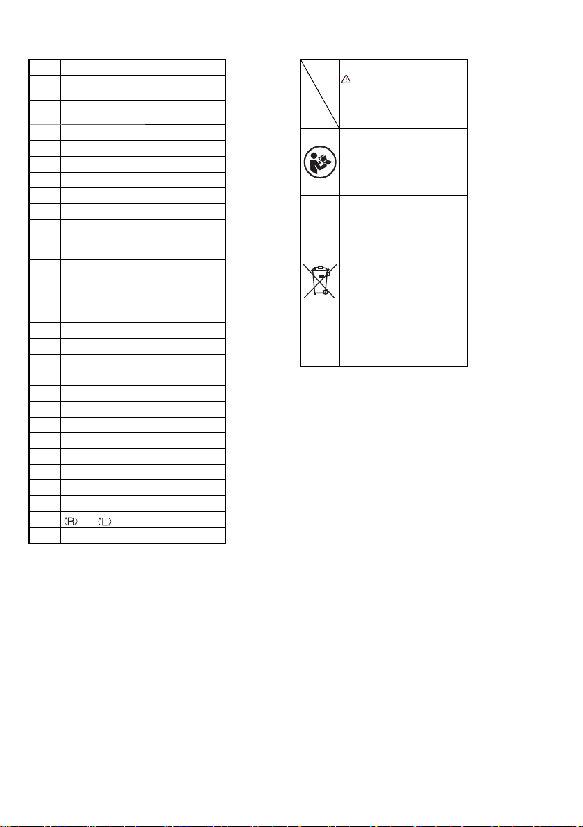
Symbols
WARNING
The following show symbols
used for the machine. Be
sure that you understand
their meaning before use.
Read all safety warnings
and all instructions.
Failure to follow the warnings
and instructions may result
in electric shock, fi re and/or
serious injury.
Only for EU countries
Do not dispose of electric
tools together with
household waste material!
In observance of European
Directive 2002/96/EC
on waste electrical and
electronic equipment
and its implementation in
accordance with national
law, electric tools that have
reached the end of their life
must be collected separately
and returned to
environmentally compatible
recycling facility.
an
4

GENERAL POWER TOOL SAFETY WARNINGS
WARNING
Read all safety warnings and all instructions.
Failure to follow the warnings and instructions may result in
electric shock, fi re and/or serious injury.
Save all warnings and instructions for future reference.
The term “power tool” in the warnings refers to your mainsoperated (corded) power tool or battery-operated (cordless)
power tool.
1) Work area safety
a) Keep work area clean and well lit.
Cluttered or dark areas invite accidents.
b) Do not operate power tools in explosive
atmospheres, such as in the presence of
fl ammable liquids, gases or dust.
Power tools create sparks which may ignite the dust
or fumes.
c) Keep
children and bystanders away while
operating a power tool.
Distractions can cause you to lose control.
2) Electrical safety
a) Power tool plugs must match the outlet.
Never modify the plug in any way.
Do not use any adapter plugs with earthed
(grounded) power tools.
Unmodifi ed plugs and matching outlets will reduce
risk of electric shock.
b) Avoid body contact with earthed or grounded
surfaces, such as
refrigerators.
There is an increased risk of electric shock if your
body is earthed or grounded.
c) Do not expose power tools to rain or wet
conditions.
Water entering a power tool will increase the risk of
electric shock.
d) Do not abuse the cord. Never use the cord for
carrying, pulling or unplugging the power tool.
Keep cord away from heat, oil, sharp edges or
moving parts.
Damaged or entangled cords increase the risk of
electric shock.
e) When operating a
extension cord suitable for outdoor use.
Use of a cord suitable for outdoor use reduces the
risk of electric shock.
f) If operating a power tool in a damp location
is unavoidable, use a residual current device
(RCD) protected supply.
Use of an RCD reduces the risk of electric shock.
3) Personal safety
a) Stay alert, watch what you are doing and use
common sense when operating a power tool.
Do not use a power tool while you are tired
or under the infl uence of drugs, alcohol or
medication.
A moment of inattention while operating power tools
may result in serious personal injury.
b) Use personal protective equipment. Always wear
eye protection.
Protective equipment such as dust mask, non-skid
safety shoes, hard hat, or hearing protection used for
appropriate conditions will reduce personal injuries.
c) Prevent unintentional starting. Ensure the
switch is in the off -position before connecting to
power source and/or
carrying the tool.
pipes, radiators, ranges and
power tool outdoors, use an
battery pack, picking up or
Carrying power tools with your fi nger on the switch or
energising power tools that have the switch on invites
accidents.
d) Remove any adjusting key or wrench before
turning the power tool on.
A wrench or a key left attached to a rotating part of the
power tool may result in personal injury.
e) Do not overreach. Keep proper footing and
balance at all times.
This enables better control of the power tool in
unexpected situations.
f) Dress properly. Do not wear loose clothing or
jewellery. Keep your hair, clothing and
away from moving parts.
Loose clothes, jewellery or long hair can be caught in
moving parts.
g) If devices are provided for the connection of
dust extraction and collection facilities, ensure
these are connected and properly used.
Use of dust collection can reduce dust related hazards.
4) Power tool use and care
a) Do not force the power tool. Use the correct
power tool for your application.
The correct power tool will do the job better and safer
at the rate for which it was designed.
b) Do
not use the power tool if the switch does not
turn it on and off .
Any power tool that cannot be controlled with the
switch is dangerous and must be repaired.
c) Disconnect the plug from the power source and/
or the battery pack from the power tool before
making any adjustments, changing accessories,
or storing power tools.
Such preventive safety measures reduce the risk of
starting the power tool accidentally.
d) Store idle power tools out
and do not allow persons unfamiliar with the
power tool or these instructions to operate the
power tool.
Power tools are dangerous in the hands of untrained
users.
e) Maintain power tools. Check for misalignment or
binding of moving parts, breakage of parts and
any other condition that may aff ect the power
tools’ operation.
If damaged, have the power tool repaired before
use.
Many accidents are caused by poorly maintained
power tools.
f) Keep cutting tools sharp and clean.
Properly maintained cutting tools with sharp cutting
edges are less likely to bind and are easier to
control.
g) Use the power tool, accessories and tool bits
etc. in accordance with these instructions,
taking into account the working conditions and
the work to be performed.
Use of the power tool for operations diff erent from those
intended could result in a hazardous situation.
5) Battery tool use and
a) Recharge only with the charger specifi ed by the
manufacturer.
A charger that is suitable for one type of battery pack
may create a risk of fi re when used with another
battery pack.
b) Use power tools only with specifi cally designated
battery packs.
Use of any other battery packs may create a risk of
injury and fi re.
of the reach of children
care
gloves
5

c) When battery pack is not in use, keep it away
from other metal objects like paper clips, coins,
keys, nails, screws, or other small metal objects
that can make a connection from one terminal to
another.
Shorting the battery terminals together may cause
burns or a fi re.
d) Under abusive conditions, liquid may be ejected
from the battery; avoid
accidentally occurs, fl ush with water. If liquid
contacts eyes, additionally seek medical help.
Liquid ejected from the battery may cause irritation or
burns.
6) Service
a) Have your power tool serviced by a qualifi ed
repair person using only identical replacement
parts.
This will ensure that the safety of the power tool is
maintained.
PRECAUTION
Keep children and infi rm persons away.
When not in use, tools should be
children and infi rm persons.
contact. If contact
stored out of reach of
CORDLESS COMBI DRILL SAFETY WARNINGS
1. Wear ear protectors with impact drills.
Exposure to noise can cause hearing loss.
2. Use auxiliary handle(s), if supplied with the tool.
Loss of control can cause personal injury.
3. Hold power tool by insulated gripping surfaces,
when performing an operation where the cutting
accessory may contact hidden wiring. Cutting
accessory contacting a "live" wire may make exposed
metal parts of the power tool "live" and could give the
operator an electric shock.
4. Hold power tool by insulated gripping surfaces,
when performing an operation where the fastener
may contact hidden wiring. Fasteners contacting a
"live" wire may make exposed metal
tool "live" and could give the operator an electric shock.
5. Always charge the battery at a temperature of 0°C –
50°C. A temperature of less than 0°C will result in over
charging which is dangerous. The battery cannot be
charged at a temperature higher than 50°C.
The most suitable temperature for charging is that of
20°C – 25°C.
6. When one charging is completed, leave the charger for
about 15 minutes before the next charging of battery.
Do not charge more than two batteries consecutively.
7. Do not allow foreign matter to enter the hole for
connecting the
8. Never disassemble the rechargeable battery and
charger.
9. Never short-circuit the rechargeable battery. Shortcircuiting the battery will cause a great electric current
and overheat. It results in burn or damage to the battery.
10. Do not dispose of the battery in fi re.
If the battery is burnt, it
11. Bring the battery to the shop from which it was purchased
as soon as the post-charging battery life becomes too
short for practical use. Do not dispose of the exhausted
battery.
12. Using an exhausted battery will damage the charger.
13. Do not insert object into the air ventilation
charger.
Inserting metal objects or infl ammables into the charger
air ventilation slots will result in electrical shock hazard or
damaged charger.
14. Do not move the charger by pulling it by the cord. Doing
so may lead to damage.
15. When mounting a bit into the keyless chuck,
sleeve adequately. If the sleeve is not tight, the bit may
slip or fall out, causing injury.
rechargeable battery.
may explode.
SPECIFICATIONS
POWER TOOL
Model DV14DVC2 DV18DVC2
No-load speed (Low/High) 0 – 400 / 0 – 1500 min
No-load impact rate (Low/High) 0 – 5600 / 0 – 21000 min
Capacity
Drilling
Brick
(Depth 30 mm)
Wood
(Thickness 18 mm)
Metal
(Thickness 1.6 mm)
13 mm 13 mm
32 mm 38 mm
13 mm 13 mm
Machine screw 6 mm 6 mm
Driving
Wood screw
8 mm (diameter) × 50 mm (length)
(Requires a pilot hole)
BCC1412: Ni-Cd 14.4 V (1.2 Ah 12 cells)
Rechargeable battery
EB1414S: Ni-Cd 14.4 V (1.4 Ah 12 cells)
BCC1415: Ni-Cd 14.4 V (1.5 Ah 12 cells)
Weight
1.8 kg 1.9 kg
CHARGER
Model UC18YG UC18YK UC18SF
Charging voltage 7.2 – 18 V 7.2 – 18 V18 V
Weight 0.3 kg 0.3 kg 0.6 kg
6
-1
-1
0 – 400 / 0 – 1500 min
0 – 5600 / 0 – 21000 min
8 mm (diameter) × 75 mm (length)
(Requires a pilot hole)
BCC1812: Ni-Cd 18 V (1.2 Ah 15 cells)
EB1814SL: Ni-Cd 18 V (1.4 Ah 15 cells)
BCC1815: Ni-Cd 18 V (1.5 Ah 15 cells)
parts of the power
slots of the
tighten the
-1
-1

STANDARD ACCESSORIES
In addition to the main unit (1), the package contains the
accessories listed in the table below.
1 Plus driver bit (No. 2 × 65L) .................... 1
DV14DVC2
DV18DVC2
Standard accessories are subject to change without notice.
2 Charger
(UC18YG or UC18YK or UC18SF) .........1
3 Battery ...................................... 1 or 2 or 3
4 Plastic case ............................................1
OPTIONAL ACCESSORIES (sold separately)
1. Battery (BCC1412, EB1414S, BCC1415)
2. Battery (BCC1812, EB1814SL, BCC1815)
Optional accessories are subject to change without notice.
(For DV14DVC2)
(For DV18DVC2)
APPLICATIONS
○ Drilling of brick and concrete block, etc.
○ Driving and removing of machine screws, wood screws,
tapping screws, etc.
○ Drilling of various metals.
○ Drilling of various woods.
BATTERY REMOVAL/INSTALLATION
1. Battery removal
Hold the handle tightly and push the battery latch (2 pcs.)
to remove the battery (see Figs. 1 and 2).
CAUTION
Never short-circuit the battery.
2. Battery installation
Insert the battery while observing its polarities (see
Fig. 2).
CHARGING
Before using the power tool, charge the battery as follows.
1. Connect the charger power cord to the receptacle
Connecting the power cord will turn on the charger.
2. Insert the battery into the charger
Insert the battery fi rmly while observing its direction,
until it contacts the bottom of the charger (See
Fig. 3, 4). (The pilot lamp on the UC18YG and UC18YK
or the battery set lamp on the UC18SF lights up.)
CAUTION
If the pilot lamp on the UC18YG and UC18YK or the
battery set lamp on the UC18SF does not light up
when the battery is inserted, pull out the
from the receptacle and check the battery mounting
condition.
(1) Regarding the temperatures of the rechargeable battery
The temperatures for rechargeable batteries are as
shown in Table 1.
Table 1 Recharging ranges of batteries
Rechargeable batteries
BCC1412, BCC1812,
EB1414S, EB1814SL,
BCC1415, BCC1815
Temperatures at which the
battery can be recharged
power cord
0°C – 45°C
(2) Regarding recharging time
Depending on the combination of the charger and
batteries, the charging time will become as shown in
Table 2.
Table 2 Charging time (At 20°C)
Charger
Battery
BCC1812
EB1814SL,
BCC1815
BCC1412
EB1414S,
BCC1415
UC18YG, UC18YK:
The pilot lamp goes off to indicate that the battery is fully
charged.
The battery charging time becomes longer when a
temperature is low or the voltage of the power source is
too low.
UC18SF:
Using
from the charger.
The battery set lamp goes off when the battery is removed
from the charger.
When the temperature of the battery is low (less than 0°
or the voltage of the power source is low, the capacity
of the battery after charging for 180 minutes is reduced.
If the battery performance seems poor during practical
use, charge for 4 to 6 hours.
CAUTION
If the battery is heated due to direct sunlight, etc.,
3. Disconnect the charger’s power cord from the
receptacle
4. Hold the charger fi rmly and pull out the battery
NOTE
After charging, pull out batteries from the charger fi rst,
and then keep the batteries properly.
Regarding electric discharge in case of new batteries,
etc.
As the internal chemical substance of new batteries and
batteries that have not been used for an extended period
is not activated, the electric discharge might be low when
using them the fi rst and second time. This is a temporary
phenomenon, and
will be restored by recharging the batteries 2 – 3 times.
UC18YG UC18YK UC18SF
Approx.
Approx.
30 min.
Approx.
30 min.
Approx.
30 min.
Approx.
30 min.
the above times as a guide, remove the battery
just after operation, the
light up. At that time, cool the battery fi rst, then start
charging.
normal time required for recharging
Approx.
50 min.
Approx.
60 min.
Approx.
50 min.
Approx.
60 min.
charger pilot lamp may not
180 min.
(Less than 0°C:
Approx.
240-360 min)
Approx.
210 min.
(Less than 0°C:
Approx.
280-420 min)
–––––
–––––
C
)
7

How to make the batteries perform longer.
(1) Recharge the batteries before they become completely
exhausted.
When you feel that the power of the tool becomes
weaker, stop using the tool and recharge its battery. If
you continue to use the tool and exhaust the electric
current, the battery may be
become shorter.
(2) Avoid recharging at high temperatures.
A rechargeable battery will be hot immediately after use.
If such a battery is recharged immediately after use, its
internal chemical substance will deteriorate, and the
battery life will be shortened. Leave the battery and
recharge it after
it has cooled for a while.
damaged and its life will
PRIOR TO OPERATION
1. Setting up and checking the work environment
Check if the work environment is suitable by following the
precautions.
HOW TO USE
1. Confi rm the clutch dial position (See Fig. 5)
The three modes of screwdriver, drill and impact drill can
be switched by the position of the cap in this unit.
(1) When using this unit as a screwdriver, line up the one of
the numbers “1, 3, 5 ... 22”
with the triangle mark on the outer body.
(2) When using this unit as a drill, align the clutch dial drill
mark “
(3) When using this unit as an impact drill, align the cap
CAUTION
○ The clutch dial cannot be set between the numerals “1, 3,
○ Do not use with the clutch dial numeral between “22”
2. Tightening torque adjustment
(1) Tightening torque
Tightening torque should correspond in its intensity to
(2)
The tightening torque diff ers depending on the type of
The unit indicates the tightening torque with the numbers
” with the triangle mark on the outer body.
hammer mark “
body.
5 ... 22” or the dots.
and the line at the middle of the drill mark. Doing so may
cause
damage (See Fig. 6).
the screw diameter. When too strong torque is used,
the screw head may be broken or be injured. Be sure
to adjust the clutch dial position according to the screw
diameter.
Tightening torque indication
screw and the material being tightened.
“1, 3, 5 ... 22” on the clutch dial, and dots. The tightening
toque at position “1” is the weakest and the
strongest at the highest number (See Fig. 5).
on the clutch dial, or the dots,
” with the triangle mark on the outer
torque is
(3) Adjusting the tightening torque
Rotate the clutch dial and line up the numbers “1, 3, 5 ...
22” on the clutch dial, or the dots, with the triangle mark
on the outer body. Adjust the clutch dial in the
the strong torque direction according to the torque you
need.
CAUTION
○ The motor rotation may be locked to cease while the unit
is used as drill. While operating the combi drill, take care
not to lock the motor.
○ Too long hammering may cause the screw broken due to
excessive tightening.
3. Rotation to Impact changeover (See Fig. 5)
The “Rotation (Rotation only)” and “Impact (Impact +
Rotation)” can be switched by aligning the drill mark “
or the hammer mark “
outer body.
○ To make holes in the metal, wood or plastic, switch to
“Rotation (Rotation only)”.
○ To make holes in bricks or concrete blocks, switch to
“Impact (Impact + Rotation)”.
CAUTION
○ If an operation which is normally performed at the
“Rotation” setting is
eff ect of making holes does not only increase but it may
also damage the bit or other parts.
○ If it is hard to turn the clutch dial to hammer mark “
position, turn the chuck slightly in either direction and then
turn the clutch dial to hammer mark “
4. Change rotation speed
Operate the shift knob to change the rotational speed.
Move the shift knob in the direction of the arrow (See
Figs. 7 and 8).
When the shift knob is set to “LOW”, the drill rotates at a
low speed. When set to “HIGH”, the
speed.
CAUTION
○ When changing the rotational speed with the shift knob,
confi rm that the switch is off .
Changing the speed while the motor is rotating will
damage the gears.
○ When setting the shift knob to “HIGH” (high speed) and
the position of the
may happen that the clutch does not engaged and that
the motor is locked. In such a case, please set the shift
knob to “LOW” (low speed).
○ If the motor is locked, immediately turn the power off . If
the motor
be burnt.
5. The scope and suggestions for uses
The usable scope for various types of work based on the
mechanical structure of this unit is shown in Table 3.
is locked for a while, the motor or battery may
” with the triangle mark on the
performed at “Impact” setting, the
drill rotates at a high
clutch dial is between “15” and “22”, it
weak or
” position again.
”
”
Drilling
Driving
8
Table 3
Work Suggestions
Brick
Wood
Steel
Aluminum
Machine screw Use the bit or socket matching the screw diameter.
Wood screw Use after drilling a pilot hole.
Use for drilling purpose.

6. How to select tightening torque and rotational speed
Table 4
Clutch Dial
Position
1 –
LOW (Low speed) HIGH (High speed)
For 6 mm or smaller diameter
screws.
For 6 mm or smaller nominal
diameter screws.
For 13 mm or smaller diameters.
For 32 mm or smaller diameters.
(DV14DVC2)
For 38 mm or smaller diameters.
(DV18DVC2)
For drilling with a metal working drill
bit.
Driving
Drilling
Use
Machine screw 1 – 22
Wood screw
Brick
Wood
Metal
Rotating speed selection (Position of the shift knob)
For 6 mm or smaller diameter
screws.
For 3.8 mm or smaller nominal
diameter screws.
For 8 mm or smaller diameters.
(DV14DVC2)
For 10 mm or smaller diameters.
(DV18DVC2)
For 18 mm or smaller diameters.
(DV14DVC2)
For 22 mm or smaller diameters.
(DV18DVC2)
CAUTION
○ The selection examples shown in Table 4 should be
considered as general standard. As diff erent types of
tightening screws and diff erent materials to be tightened
are used in actual works proper adjustments are naturally
necessary.
○ When using the combi drill with a machine screw at HIGH
(high speed), a screw may damage or a bit may loose
due to the tightning torque is too strong. Use the combi
drill at LOW (low speed) when using a machine screw.
NOTE
The use of the battery BCC1412 and BCC1812 in
a cold condition (below 0 degree Centigrade) can
sometimes result
reduced amount of work. This, however, is a temporary
phenomenon, and returns to normal when the battery
warms up.
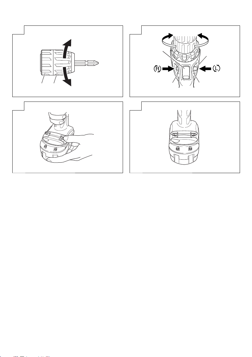
7. Mounting and dismounting of the bit
(1) After inserting a driver bit, etc. into the keyless drill chuck,
fi rmly grasp the ring and tighten the
toward the right (in the clockwise direction as viewed
from the front) (See Fig. 9).
○ If the sleeve becomes loose during operation, tighten it
further. The tightening force becomes stronger when the
sleeve is tightened additionally.
(2) Dismounting the bit
Firmly grasp the ring and loosen
it toward the left (in the counter-clockwise direction as
viewed from the front) (See Fig. 9).
CAUTION
When it is no longer possible to loosen the sleeve, use a
vise or similar instrument to secure the bit. Set the clutch
mode between 1 and 11 and then
loose side (left side) while operating the clutch. It should
be easy now to loosen the sleeve.
8. Confi rm that the battery is mounted correctly
9. Check the rotational direction
The bit rotates clockwise (viewed from the rear side) by
pushing the R-side of the
The L-side of the selector button is pushed to turn the bit
counterclockwise (See Fig. 10) (The
are provided on the body).
CAUTION
Always use this unit with clockwise rotation, when using it
as an impact drill.
in the weakened tightening torque and
sleeve by turning it
the sleeve by turning
turn the sleeve to the
selector button.
and marks
10. Switch operation
○ When the trigger switch is depressed, the tool rotates.
When the trigger is released, the tool stops.
○ The rotational speed of the drill can be controlled by
varying the amount that the trigger switch is pulled.
Speed is low when the trigger switch is pulled slightly and
increases as the trigger switch is pulled more.
NOTE
A buzzing noise is produced when the motor is about to
rotate; This is only a noise, not a machine failure.
11. For drilling into brick
Excessive pressing force never increases drilling speed.
It will not only damage the drill tip or reduce
effi ciency, but could also shorten the service life of drill
bit. Operate the combi drill within 10-15 kg pressing force
while drilling into brick.
12. Using the bit holder
CAUTION
○ Stow the bit in the specifi ed location on the tool. If the tool
is used with the bit
cause bodily injury.
○ Do not stow bits that are of a diff erent length, gauge or
dimension than the plus driver bit (65 mm long) included
in the STANDARD ACCESSORIES.
The bit may fall and cause bodily injury.
(1) Removing the bit
Securely
the tip with your thumb (Fig. 11).
(2) Installing the Bit
Install the bit with steps opposite of when removing.
Insert the bit so that the right and left sides are equal, as
shown in Fig. 12
stowed improperly, the bit may fall and
hold the main unit and pull out the bit by holding
working
MAINTENANCE AND INSPECTION
1. Inspecting the tool
Since use of as dull tool will degrade effi ciency and cause
possible motor malfunction, sharpen or replace the tool
as soon as abrasion is noted.
2. Inspecting the mounting screws
Regularly inspect all mounting screws and ensure that
they are properly tightened. Should any of the
loose, retighten them immediately. Failure to do so could
result in serious hazard.
screws be
9

3. Maintenance of the motor
The motor unit winding is the very “heart” of the power
tool.
Exercise due care to ensure the winding does not
become damaged and/or wet with oil or water.
4. Cleaning on the outside
When the combi drill is stained, wipe with a soft dry cloth
or a cloth moistened with soapy water. Do not use chloric
solvents, gasoline or paint thinner, for they melt plastics.
5. Storage
Store the combi drill in a place in which the temperature
is less than 40°C and out of reach of children.
6. Service parts list
CAUTION
Repair, modifi cation and inspection
Tools must be carried out by a Hitachi Authorized Service
Center.
This Parts List will be helpful if presented with the tool to
the Hitachi Authorized Service Center when requesting
repair or other maintenance.
In the operation and maintenance of power tools, the
safety regulations and standards
country must be observed.
MODIFICATIONS
Hitachi Power Tools are constantly being improved
and modifi ed to incorporate the latest technological
advancements.
Accordingly, some parts may be changed without prior
notice.
Important notice on the batteries for the Hitachi
cordless power tools
Please always use one of our designated genuine
batteries. We cannot guarantee the safety and
performance of our cordless power tool when used with
batteries other than these designated by us, or when
the battery is disassembled and modifi ed
disassembly and replacement of cells or other internal
parts).
of Hitachi Power
prescribed in each
(such as
Information concerning airborne noise and vibration
The measured values were determined according to
EN60745 and declared in accordance with ISO 4871.
Measured A-weighted sound power level: 96 dB (A)
Measured A-weighted sound pressure level: 85 dB (A)
Uncertainty KpA: 3 dB (A).
Wear hearing protection.
Vibration total values (triax vector sum) determined according
to EN60745.
Impact drilling into concrete:
Vibration emission value
Uncertainty K = 2.4 m/s
Drilling into metal:
Vibration emission value
Uncertainty K = 1.5 m/s
The declared vibration total value has been measured in
accordance with a standard test method and may be used
for comparing one tool with another.
It may also be used in a preliminary assessment of
exposure.
WARNING
○ The vibration emission during actual use of the power
tool can diff er from the
the ways in which the tool is used.
○ To identify safety measures to protect the operator
that are based on an estimation of exposure in the
actual conditions of use (taking account of all parts of
the operating cycle such as the times when the
switched off and when it is running idle in addition to the
trigger time).
а
= 13.5 m/s
h, ID
2
а
= 2.4 m/s
h, ID
2
declared total value depending on
2
2
tool is
GUARANTEE
We guarantee Hitachi Power Tools in accordance with
statutory/country specifi c regulation. This guarantee does
not cover defects or damage due to misuse, abuse, or normal
wear and tear. In case of complaint, please send the Power
Tool, undismantled, with the GUARANTEE CERTIFICATE
found at the end of this Handling instruction,
Authorized Service Center.
NOTE
Due to HITACHI’s continuing program of research and
development, the specifi cations herein are subject to change
without prior notice.
10
to a Hitachi

Part Name Q’TY
Item
No.
1
1
CHARGER UC18YG/UC18YK
(DV14DVC2, DV18DVC2)
CHARGER UC18FS
(UC18DVC2)
41 SWITCH TERMINAL 1
42 INTERNAL WIRE 150L 1
43 TERMINAL SUPPORT (A) 1
44-1 BATTERY : DV18DVC2 2
44-2 BATTERY : DV14DVC2 2
501-1
501-2
502 PLUS DRIVER BIT (C) 1
503 CASE 1
Part Name Q’TY
Item
No.
1
FLAT HD. SCREW (A) (LEFT
HAND) M6 × 25
1
2 KEYLESS CHUCK 13MM 1
3 GEAR BOX ASS’Y 1
4 CLUTCH DIAL 1
5 CLICK SPRING 1
6 O-RING 1
7 SPINDLE 1
8 SPRING (C) 1
9 RATCHET (B) 1
10 WASHER (A) 1
11 NUT 1
12 WASHER 1
13 SLIP BLOCK 2
14 STOPPER SPRING 2
15 FRONT CASE 1
16 SPRING (A) 4
17 STEEL BALL D5 4
18 RING GEAR 1
19 CARRIER 1
20 PLANET GEAR (C) 3
21 WASHER (A) 1
22 REAR CASE 1
26 PINION (C) 1
27 PLANET GEAR (A) 6
23 TAPPING SCREW D3 × 12 4
24 SHIFT ARM 1
28 PINION (B) 1
25 SLIDE RING GEAR 1
2
MACHINE SCREW
(W/SP. WASHER) M4 × 6
29 FIRST RING GEAR 1
30 WASHER (B) 1
31 MOTOR SPACER 1
32
33 HOUSING (A) (B) SET 1
34 HITACHI LABEL 1
9
TAPPING SCREW
(W/FLANGE) D3 × 16
35 PUSHING BUTTON 1
36 MOTOR 1
37 SHIFT KNOB 1
38
39 NAME PLATE 1
40 INTERNAL WIRE 100L 1
11

12

English Nederlands
GUARANTEE CERTIFICATE
1 Model No.
2 Serial No.
3 Date of Purchase
4 Customer Name and Address
5 Dealer Name and Address
(Please stamp dealer name and address)
1 Modelnummer
2 Serienummer
3 Datum van aankoop
4 Naam en adres van de gebruiker
5 Naam en adres van de handelaar
(Stempel a.u.b. naam en adres vande de
handelaar)
Deutsch Español
GARANTIESCHEIN
1 Modell-Nr.
2 Serien-Nr.
3 Kaufdaturn
4 Name und Anschrift des Kunden
5 Name und Anschrift des Händlers
(Bitte mit Namen und Anschrift des Handlers
abstempeln)
Français Português
1 Número de modelo
2 Número de serie
3 Fecha de adquisición
4 Nombre y dirección del cliente
5 Nombre y dirección del distribudor
(Se ruega poner el sello del distribudor con su
nombre y dirección)
CERTIFICAT DE GARANTIE
1 No. de modèle
2 No de série
3 Date d’achat
4 Nom et adresse du client
5 Nom et adresse du revendeur
(Cachet portant le nom et l'adresse du
revendeur)
Italiano
1 Número do modelo
2 Número do série
3 Data de compra
4 Nome e morada do cliente
5 Nome e morada do distribuidor
(Por favor, carímbe o nome e morada do
distribuidor)
CERTIFICATO DI GARANZIA
1 Modello
2 N° di serie
3 Data di acquisto
4 Nome e indirizzo dell'acquirente
5 Nome e indirizzo del rivenditore
(Si prega di apporre il timbro con questi dati)
GARANTIEBEWIJS
CERTIFICADO DE GARANTÍA
CERTIFICADO DE GARANTIA
13

1
2
3
4
5
14

Hitachi Power Tools Europe GmbH
Siemensring 34, 47877 willich 1, F. R. Germany
Tel: +49 2154 49930
Fax: +49 2154 499350
URL: http://www.hitachi-powertools.de
Hitachi Power Tools Netherlands B. V.
Brabanthaven 11, 3433 PJ Nieuwegein, The Netherlands
Tel: +31 30 6084040
Fax: +31 30 6067266
URL: http://www.hitachi-powertools.nl
Hitachi Power Tools (U. K.) Ltd.
Precedent Drive, Rooksley, Milton Keynes, MK 13, 8PJ, United Kingdom
Tel: +44 1908 660663
Fax: +44 1908 606642
URL: http://www.hitachi-powertools.co.uk
Hitachi Power Tools France S. A. S.
Prac del’ Eglantier 22, rue des Crerisiers Lisses, C. E. 1541,
91015 EVRY CEDEX, France
Tel: +33 1 69474949
Fax: +33 1 60861416
URL: http://www.hitachi-powertools.fr
Hitachi Power Tools Belgium N.V. / S.A.
Koningin Astridlaan 51, 1780 Wemmel, Belgium
Tel: +32 2 460 1720
Fax: +32 2 460 2542
URL http://www.hitachi-powertools.be
Hitachi Fercad Power Tools Italia S.p.A
Via Retrone 49-36077, Altavilla Vicentina (VI), Italy
Tel: +39 0444 548111
Fax: +39 0444 548110
URL: http://www.hitachi-powertools.it
Hitachi Power Tools lberica, S.A.
C / Migjorn, s/n, Poligono Norte, 08226 Terrassa, Barcelona, Spain
Tel: +34 93 735 6722
Fax: +34 93 735 7442
URL: http://www.hitachi-powertools.es
Hitachi Power Tools Österreich GmbH
Str. 7, Objekt 58/A6, Industriezentrum NÖ –Süd 2355
Wiener Neudorf, Austria
Tel: +43 2236 64673/5
Fax: +43 2236 63373
15

EC DECLARATION OF CONFORMITY
We declare under our sole responsibility that this product is in conformity with standards or standardization documents
EN60745, EN60335, EN55014 and EN61000 in accordance with Directives 2004/108/EC, 2006/95/EC and 2006/42/EC.
This product also conforms to RoHS Directive 2011/65/EU.
The European Standards Manager at Hitachi Koki Europe Ltd. is authorized to compile
the technical fi le.
This declaration is applicable to the product affi xed CE marking.
Representative offi ce in Europe
Hitachi Power Tools Europe GmbH
Siemensring 34, 47877 Willich 1, F. R. Germany
Technical fi le at:
Hitachi Koki Europe Ltd.
Clonshaugh Business & Technology Park, Dublin 17, lreland
Head offi ce in Japan
Hitachi Koki
Shinagawa Intercity Tower A, 15-1, Konan 2-chome,
Minato-ku, Tokyo, Japan
Co., Ltd.
29. 3. 2013
F. Tashimo
Vice-President & Director
303
Code No. C99208211 G
Printed in China
 Loading...