

Hitachi DV 14DCL2, DV 14DVC2, DV 18DCL2, DV 18DVC2 Service Manual
DV 18DCL2
International Sales Division
LIST Nos.
DV 14DCL2: H866
DV 14DVC2: H868
DV 18DCL2: H867
DV 18DVC2: H869
Jun. 2010
PRODUCT NAME
Hitachi 14.4 V Cordless Imp act Driver Drill
Models DV 14DCL2, DV 14DVC2
Hitachi 18 V Cordless Impact Driver Drill
Models DV 18DCL2, DV 18DVC2
D
REP AIR GUIDE ----------------------------------------------------------------------------------------------------------------- 1
1. Precautions on disassembly and reassembly ------------------------------------------------------------ 1
2. Precautions on disassembly and reassembly of battery charger ------------------------------------9
STANDARD REPAIR TIME (UNIT) SCHEDULES ------------------------------------------------------------------- 10
CONTENTS
Page

-1-
Be sure to remove the storage batteries from the main body before servicing. Inadvertent triggering of the
switch with the storage battery connected imposes the danger of the motor accidently turning.
1. Precautions on Disassembly and Reassembly
[Bold] numbers in the descriptions below correspond to item numbers in the Parts List and exploded
assembly diagrams for the Models DV 18DCL2, DV 18DVC2, DV 14DCL2 and DV 14DVC2.
1. Removal of Housing (A).(B) Set
First, align the drill mark " " on the Clutch Dial [4] with the triangle mark on Housing (A).(B) Set [33].
Remove the eight Tapping Screw (W/Flange) D3 x 16 (Black) [38] from the main body. Gently open
Housings (A) and (B) while holding the battery loading sections.
2. Removal of internal parts
After removal of Housing (B), all internal parts (assembled or separated) can be taken out as a single unit.
Lift the entire contents from Housing (A) while holding the Motor [36] and C lutch Dial [4].
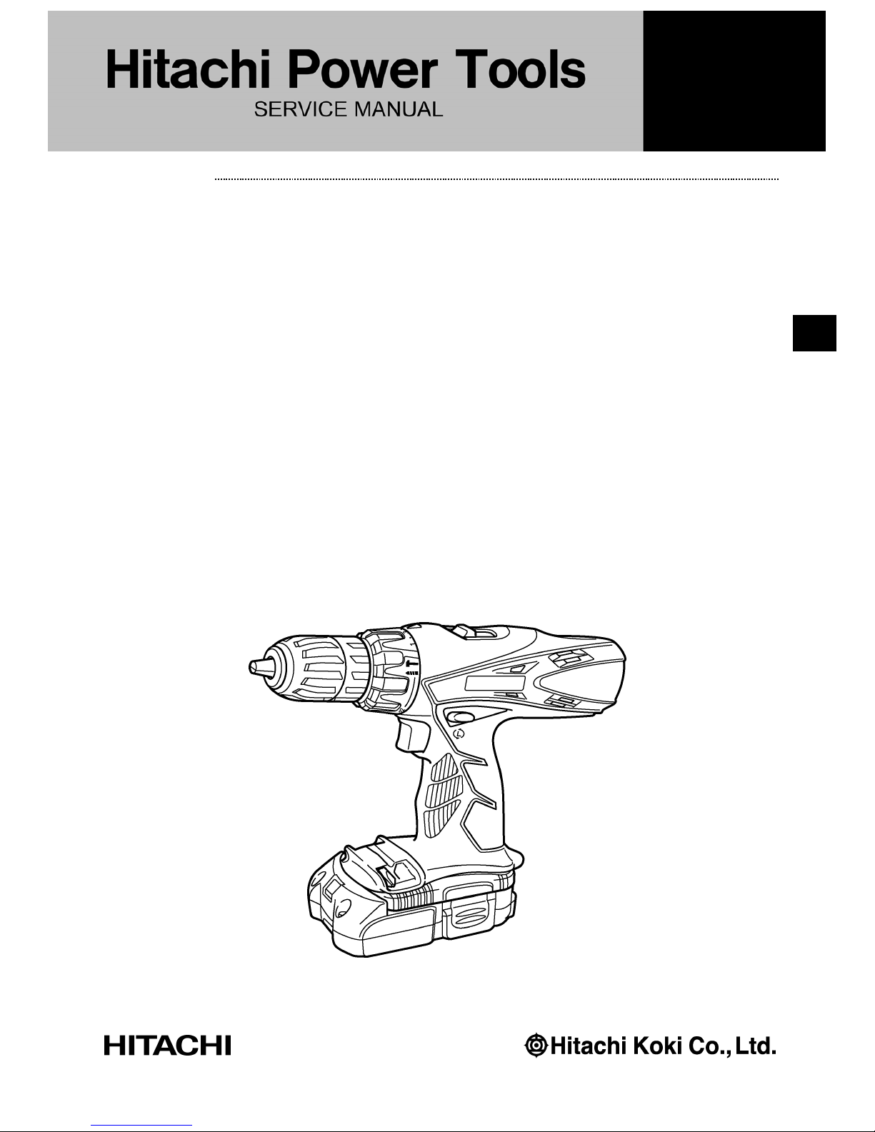
3. Removal of the Drill Chuck 13VLRS-N (See Fig. 1.)
(a) Turn the Motor [36] counterclockwise (when viewed from the rear) and remove it from the Rear Case
[22]. Remove the Shift Knob [37] from the Shift Arm [24]. Be careful not to remove the Shift Arm [24]
from the Rear Case [22] in this operation.
(b) Attach the motor spacer to the assembly of the Drill Chuck 13VLRS-N [2], Clutch Dial [4], Front Case
[15] and Rear Case [22], and then mount the assembly on special repair tool J-348 clamped in the vise
as illustrated in Fig. 1. In this operation, confirm that the pinions press-fitted in the special repair tool J-
342 and Planet Gear (A) Set [27] are properly engaged.
(c) Secure the Slide Ring Gear [25] to the Front Case [15] side with the Shift Arm [24].
(d) Turn the sleeve of the Drill Chuck 13VLRS-N [2] counterclockwise (when viewed from the front) to fully
open the jaws of the Drill Chuck 13VLRS-N [2]. Turn Flat Hd. Screw (A) (Left Hand) M6 x 25 [1]
clockwise and remove it. (Note that the special screw is left-hand threaded.)
(e) Fit the hexagonal bar wrench M10 into the Drill Chuck 13VLRS-N [2] as illustrated in Fig. 1, and then
turn the wrench counterclockwise to remove the Drill Chuck 13VLRS-N [2].
REPAIR GUIDE
Disassembl
y
-2-
4. Disassembly of the gear unit
Remove the Shift Arm [24] from the Rear Case [22]. Turn Washer (B) [30] mounted in the Rear Case [22]
counterclockwise to remove it. Take out the First Ring Gear [29], Planet Gear (A) Set [27], Pinion (B) [28],
Pinion (C) [26] and Slide Ring Gear [25]. Then remove the Screw Set D3 x 12 [23] (4 pcs.) connecting the
Front Case [15] and Rear Case [22]. Remove Washer (A) [21], Planet Gear (C) Set [20] (3 pcs.), the
Carrier [19], Ring Gear [18], W asher (A) [10], four S teel Balls D5 [17], four Springs (A) [16] and Front Ca se
[15] in that order. Be careful not to lose the four Steel Balls D5 [17] during this operation.
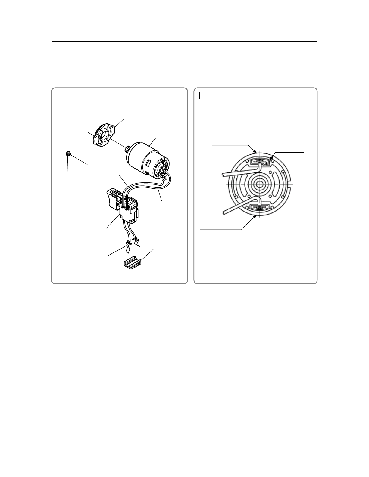
5. Disassembly of the clutch unit
(a) Remove the Clutch Dial [4] from the Nut [11]. Then remove the Click Spring [5] from the Front Case
[15]. Next, remove the Spindle [7], Ratchet (B ) [9] and Washer (A) [10] in that order.
(b) Turn the Nut [11] counterclockwise a nd remove it from the Front Case [15]. Then remove the Washer
[12], Slip Block [13] and Stopper Spring [14].
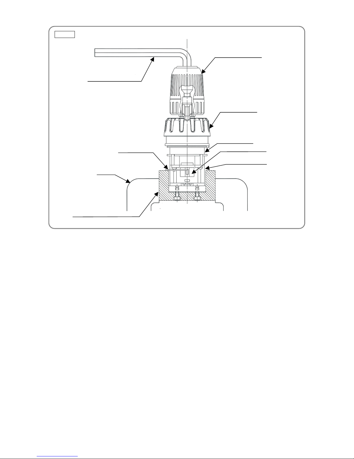
6. Disassembly of the power supply unit
NOTE: Do not remove the heat sink secured to the Switch Terminal [41] with a s crew.
Remove the two Machine Screws (W/S p. W a sher) M4 x 6 [32], an d then separ ate the Moto r [36] and Motor
Spacer [31]. Disconnect the Internal Wire (Black) [40] and Internal Wire (Red) [42] from the Motor [36] with
a soldering iron, and then disconnect both wires from the Switch Terminal [41] in the same manner.
Disconnect Termin al Support (A) [43].
Hexagonal bar wrench
Drill Chuck 13VLRS-N [2]
Clutch Dial [4]
Front Case [15]
Slide Ring Gear [25]
Rear Case [22]
Shift Arm [24]
Vise
Special repair tool (J-348)
Fig. 1
-3-
Motor Spacer [31]
Machine Screw
(
W/Sp. Washer) M4 x 6 [32
]
Motor [36]
Internal Wire
(Red) [42]
Internal Wire
(Black) [40]
Switch Terminal [41]
Terminal Support
(A) [43]
Terminal
Generally conduct reassembly by reversing the disassembly procedures, and note the following items:
1. Reassembly of the power supply unit
(a) Perform wiring according to the wiring diagram (Fig. 2).
(b) Pay attention to the polarity of the Motor [36] when soldering the Internal Wire (Black) [40] and Internal
Wire (Red) [42] to the Motor [36]. The red-marked side of the Motor [36] is positive. (See Fig. 3.)
(c) Insert the terminal while being careful about the direction of Terminal Support (A) [43].
(d) Apply grease (Hitachi Motor Grease No. 29, Code No. 930035 recommended) to the press-fitted Motor
[36] shaft.
2. Reassembly of the clutch unit
(a) Mount Washer (A) [10], Ratchet (B) [9], Spring (C) [8], the Spindle [7] and Washer [12] onto the Front
Case [15] in that order. When mounting the Spindle [7], press in the outside of the ball bearing. Then
mount the Slip Block [13] and Stopper Spring [14] inside the Front Case [15]. (See Fig. 4.)
Reassembl
y
Red mark
Positive side
Negative side
Fig. 2
Fig. 3
-4-
Fig. 4
Clutch Dial [4]
Click Spring [5]
O-ring [6]
Spindle [7]
Spring (C) [8]
Ratchet (B) [9]
Washer (A) [10]
Nut [11]
Washer [12]
Slip Block [13]
Stopper Spring [14]
Front Case [15]
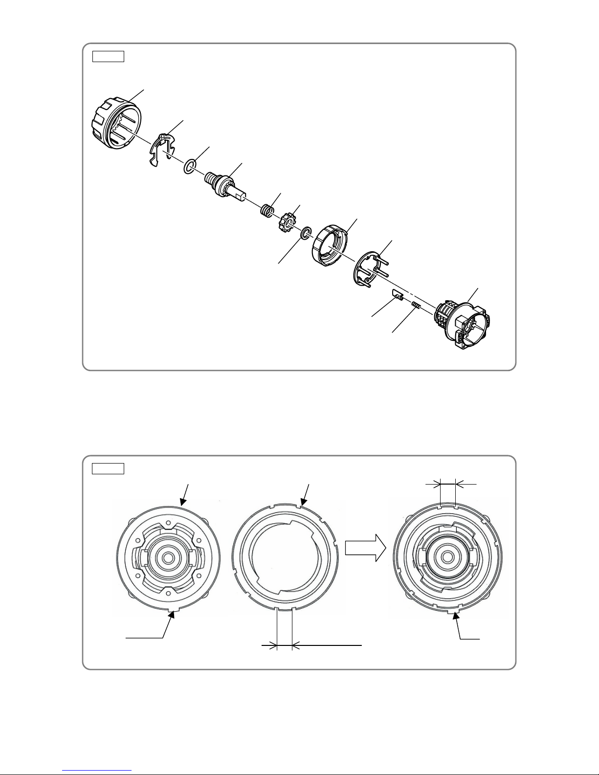
(b) Mount the Nut [11] onto the F ront Case [15]. (See Fig. 5.)
Align rib (A) on the Front Case [15] with short interval (B) on the Nut [11]. Rotate the Nut [11] about
one-half turn clockwise so that rib (A) on the Front Case [15] and short interval (B) on the Nut [11] are
positioned on opposite sides.
Fig. 5
Rib (A)
Front Case [15] Nut [11]
One-half turn
clockwise
(A)
Short interval (B)
(B)
-5-
Groove
Groove
Rib
Rib
Protrusion
Front Case [15]
Click Spring [5]
Groove
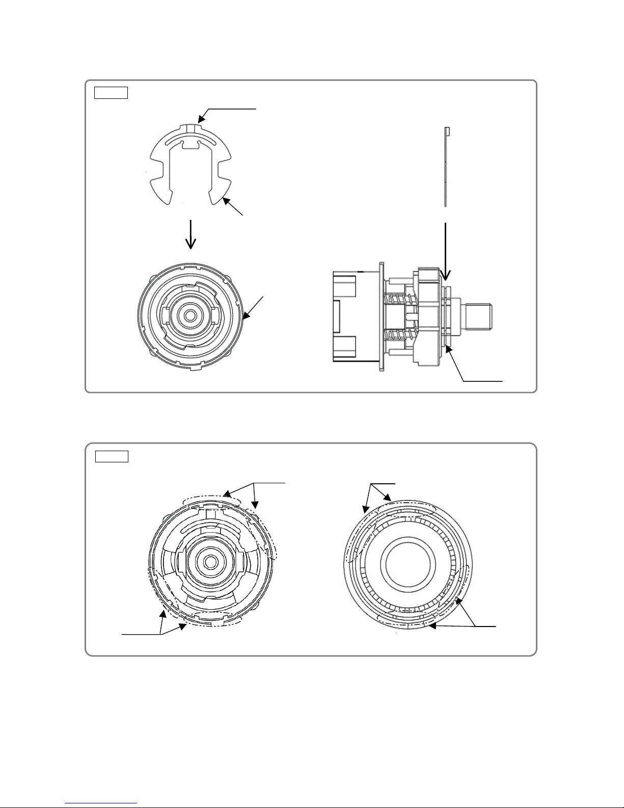
(c) With the protrusion on the Click Spring [5] facing upward, securely insert the Click Spring [5] into the
groove of the Front Case [15]. (See Fig. 6.)
(d) Mount the Clutch Dial [4] onto the Front Case [15]. (See Fig. 7.) Mount the Nut [11] onto the Clutch Dial
[4] by aligning the ribs on the Clutch Dial [4] with the grooves on the Nut [11].
Fig. 6
Fig. 7
-6-
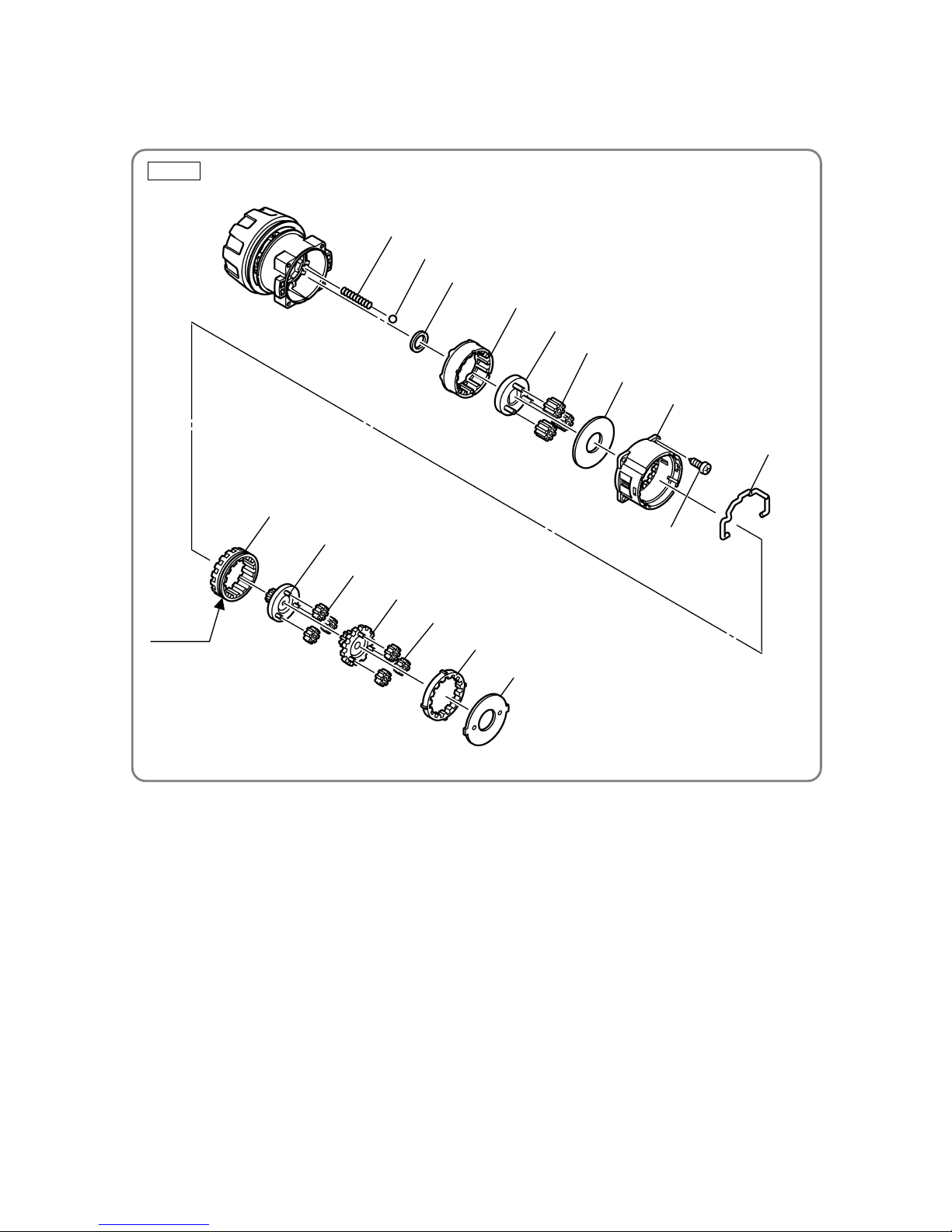
3. Reassembly of the gear unit
(a) Apply grease (Hitachi Motor Grease No. 29, Code No. 930035) to the meshing portions of each gear.
(b) Reassemble the parts of the gear unit in order. (See Fig. 8.)
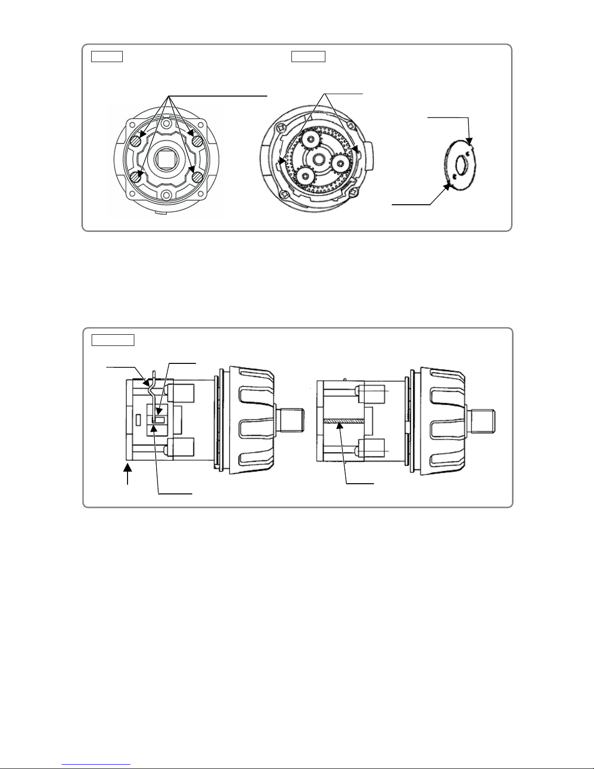
(1) Position Spring (A ) [16] (4 pcs.) and Steel Ball D5 [17] (4 pcs.) as illustrated in Fig. 9.
(2) Pay attention to the direction of the groove when mounting the Slide Ring Gear [25], so that the
groove faces toward the Motor [36].
(3) Mount the Front Case [15] and Rear Case [22] so that the positioning groove matches the rib.
(4) Fit Washer (B) [30] in the Rear Case [22] so that the protrusions of Washer (B) [30] fit into the
recesses on the Rear Case [22]. Then fully turn Washer (B) [30] clockwise until it stops.
(See Fig. 10.)
Steel Ball D5 [17]
Washer (A) [10]
Ring Gear [18]
Carrier [19]
Planet Gear (C) Set [20]
Washer (A) [21]
Spring (A) [16]
Rear Case [22]
Screw Set
D3 x 12 [23]
Shift Arm [24]
Slide Ring Gear [25]
Pinion (C) [26]
Planet Gear (A) Set [27]
Pinion (B) [28]
Planet Gear (A) Set [27]
First Ring Gear [29]
Washer (B) [30]
Groove
Fig. 8
-7-
(c) Mount the Shift Arm [24] i nto the groove of the Rear Case [22] reassembled in step (b) above.
Facing the ridge of the Shift Arm [24] toward the Motor [36] side, mount the Shift Arm [24] on the
unmarked side of the assembly that was reassembled in step (b) above. Then insert the protrusions of
the Shift Arm [24] into the holes of the Rear Case [22] and make sure that the protrusions fit into the
grooves of the Slide Ring Gear [25] mounted in the Rear Case [22]. (See Fig. 11.)
(d) Mount the Drill Chuck 13VLRS-N [2].
Mount the Drill Chuck 13VLRS-N [2] by using the special repair to ol (J-348, Code No. 349-886), and
then secure it with Flat Hd. Screw (A) (Left Hand) M6 x 25 [1].
(e) Mount the Shift Knob [37] onto the assembly that was reassembled in step (d) above.
When mounting the Shift Knob [37] to the Shift Arm [24], check that the “LOW” mark on the Shift Knob
[37] faces the Motor [36] with the Shift Arm [24] fitted into the recess of the Shift Knob [37].
Hole
Ridge
Groove
C
View of C
Mark
Fig. 9 Fig. 10
Position of Spring (A) [16]
and Steel Ball D5 [17]
Recesses
Recess
Recess
Fig. 11
-8-
Recess
Housing (A)
Protrusion
Protrusion
Groove
(f) Mount the assembly that was reassembled in step (1)
and the assembly reassembled in step (e) above
together. (See Fig. 12.) Fit the protrusion of the Motor
Spacer [31] into the recess of the Rear Case [22],
while ensuring that the Shift Knob [37] is aligned with
the positive side of the Motor [36]. Turn the Motor
Spacer [31] clockwise as viewed from the rear of the
Motor [36] until it stops. During reassembly, make sure
that the pinions press-fitted onto the shaft of the Motor
[36] and Planet Gear (A) Set [27] mesh properly.
4. Mounting the assembly reassembled in step (3) to Housing (A).(B) Set
(a) Mount the assembly that was reassembled in step (3) above to Housing (A). Confirm that the
protrusions of the Front Case [15] and Motor Spacer [31] are engaged in the recesses of Housing (A),
and that the protrusions of Housing (A) fit into the groove of the Clutch Dial [4]. (See Fig. 13.)
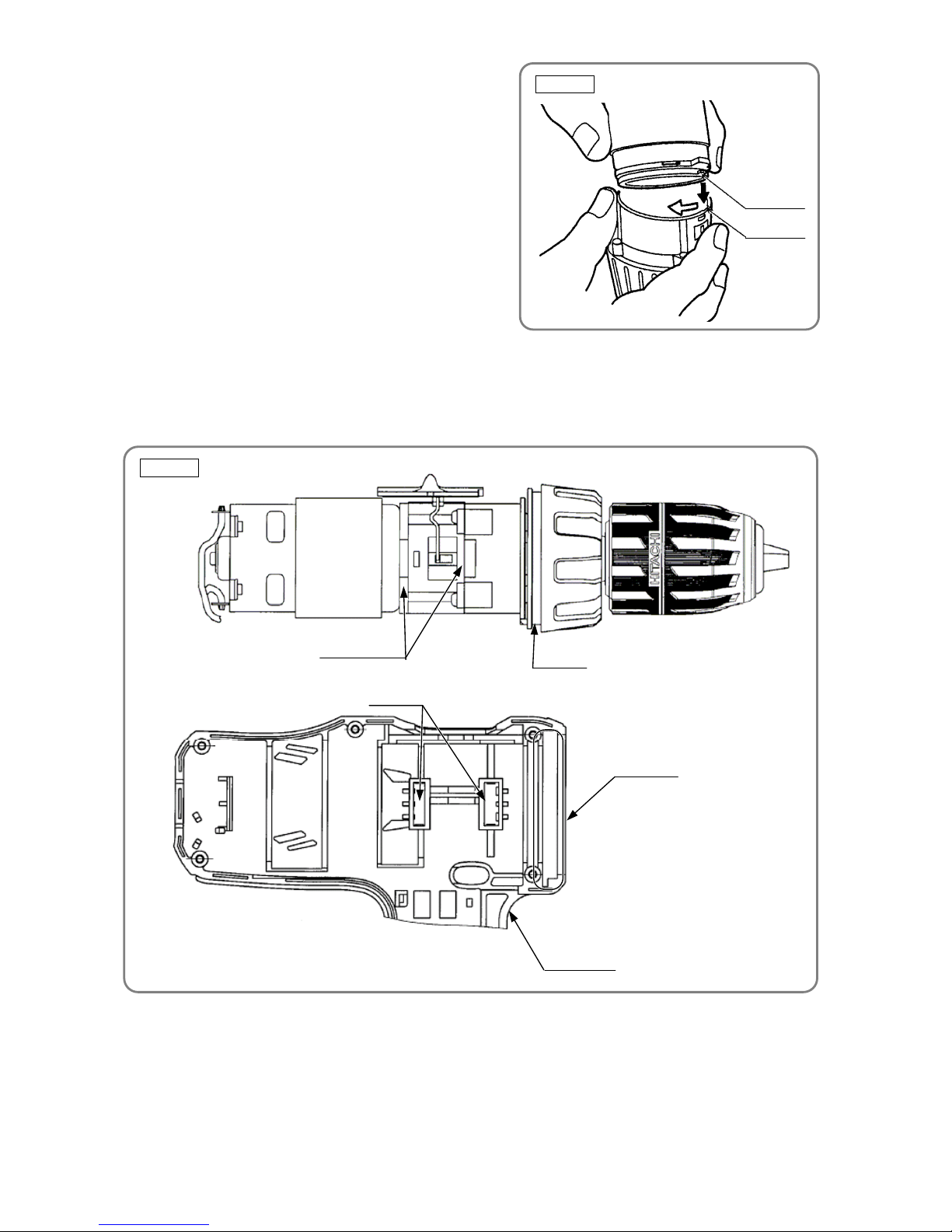
(b) Mount the Switch Terminal [41] to Housing (A). Insert Terminal Support (A) [43] to Housing (A), while
being careful about the positioning of internal wires of the Switch Terminal [41]. (See Fig. 14.)
(c) Mount the Pushing Button [35] to Housing (A). Confirm that the protrusion of the forward/reverse
changeover lever of the Switch Terminal [41] is inserted into the groove of the Pushing Button [35].
(d) Mount the assembly that was reassembled in step (c) above to Housing (B), and then secure both with
the nine Tapping Screw (W/Flange) D3 x 16 (Black) [38].
Fig. 13
Protrusion
Recess
Fig. 12
 Loading...