

Hitachi DV 16VSS, DV 13SS, DV 13VSS, DV 16SS User Manual
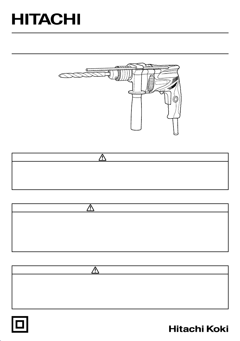
Model Hammer Drill
Modèle Perceuse percussion
Modelo Taladro de percusion
DV 13SS • DV 16SS
DV 13VSS • DV 16VSS
SAFETY INSTRUCTIONS AND INSTRUCTION MANUAL
WARNING
IMPROPER OR UNSAFE use of this power tool can result in death or serious bodily injury!
This manual contains important information about product safety. Please read and
understand this manual BEFORE operating the power tool. Please keep this manual
available for other users and owners before they use the power tool. This manual should
be stored in safe place.
INSTRUCTIONS DE SECURITE ET MODE D’EMPLOI
AVERTISSEMENT
Une utilisation INCORRECTE OU DANGEREUSE de cet outil motorisé peut entraîner la
mort ou de sérieuses blessures corporelles !
Ce mode d’emploi contient d’importantes informations à propos de la sécurité de ce
produit. Prière de lire et de comprendre ce mode d’emploi AVANT d’utiliser l’outil
motorisé. Garder ce mode d’emploi à la disponibilité des autres utilisateurs et
propriétaires avant qu’ils utilisent l’outil motorisé. Ce mode d’emploi doit être conservé
dans un endroit sûr.
INSTRUCCIONES DE SEGURIDAD Y MANUAL DE INSTRUCCIONES
ADVERTENCIA
¡La utilización INAPROPIADA O PELIGROSA de esta herramienta eléctrica puede resultar
en lesiones de gravedad o la muerte!
Este manual contiene información importante sobre la seguridad del producto. Lea y
comprenda este manual ANTES de utilizar la herramienta eléctrica. Guarde este manual
para que puedan leerlo otras personas antes de utilizar la herramienta eléctrica. Este
manual debe ser guardado en un lugar seguro.
DOUBLE INSULATION
DOUBLE ISOLATION
AISLAMIENTO DOBLE
English
IMPORTANT SAFETY INSTRUCTIONS ............... 3
MEANINGS OF SIGNAL WORDS ........................ 3
SAFETY ...................................................................... 3
GENERAL POWER TOOL SAFETY WARNINGS .... 3
SPECIFIC SAFETY RULES AND SYMBOLS ......... 4
DOUBLE INSULATION FOR SAFER
OPERATION ................................................... 5
FUNCTIONAL DESCRIPTION .................................... 7
NAME OF PARTS .................................................. 7
SPECIFICATIONS .................................................. 7
CONTENTS
Page
ASSEMBLY AND OPERATION ................................. 8
APPLICATIONS ..................................................... 8
PRIOR TO OPERATION ......................................... 8
HOW TO USE ...................................................... 10
MAINTENANCE AND INSPECTION ....................... 11
ACCESSORIES ......................................................... 12
STANDARD ACCESSORIES ............................... 12
OPTIONAL ACCESSORIES ................................. 12
PARTS LIST .............................................................. 33
Page
Français
CONSIGNES DE SÉCURITÉ IMPORTANTES ..... 13
SIGNIFICATION DES MOTS
D’AVERTISSEMENT .................................... 13
SECURITE ................................................................ 13
AVERTISSEMENTS DE SÉCURITÉ GÉNÉRAUX
CONCERNANT LES OUTILS ÉLECTRIQUES
REGLES DE SECURITE SPECIFIQUES
ET SYMBOLES ............................................. 15
DOUBLE ISOLATION POUR UN
FONCTIONNEMENT PLUS SUR ................. 16
DESCRIPTION FONCTIONNELLE ........................... 17
NOM DES PARTIES ............................................ 17
SPECIFICATIONS ................................................ 17
TABLE DES MATIERES
Page
... 13
Español
INSTRUCCIONES IMPORTANTES SOBRE
SEGURIDAD ................................................. 23
SIGNIFICADO DE LAS PALABRAS
DE SEÑALIZACIÓN ...................................... 23
SEGURIDAD ............................................................. 23
ADVERTENCIAS DE SEGURIDAD GENERAL
DE LA HERRAMIENTA ELÉCTRICA ............ 23
NORMAS Y SÍMBOLOS
ESPECÍFICOS DE SEGURIDAD ................... 25
AISLAMIENTO DOBLE PARA OFRECER
UNA OPERACIÓN MÁS SEGURA .............. 26
DESCRIPCIÓN FUNCIONAL .................................... 27
NOMENCLATURA ............................................... 27
ESPECIFICACIONES ............................................ 27
Página
ASSEMBLAGE ET FONCTIONNEMENT ................ 18
ENTRETIEN ET INSPECTION .................................. 21
ACCESSOIRES ......................................................... 22
LISTE DES PIECES .................................................. 33
ÍNDICE
MONTAJE Y OPERACIÓN ...................................... 28
MANTENIMIENTO E INSPECCIÓN ........................ 31
ACCESORIOS ........................................................... 32
LISTA DE PIEZAS .................................................... 33
Page
APPLICATIONS ................................................... 18
AVANT L’UTILISATION ...................................... 18
UTILISATION ....................................................... 20
ACCESSOIRES STANDARD ............................... 22
ACCESSOIRES SUR OPTION ............................. 22
Página
APLICACIONES ................................................... 28
ANTES DE LA OPERACIÓN ................................ 28
COMO SE USA .................................................... 30
ACCESORIOS ESTÁNDAR ................................. 32
ACCESORIOS OPCIONALES .............................. 32

English
IMPORTANT SAFETY INSTRUCTIONS
Read and understand all of the safety precautions, warnings and operating instructions in the Instruction Manual
before operating or maintaining this power tool.
Most accidents that result from power tool operation and maintenance are caused by the failure to observe basic
safety rules or precautions. An accident can often be avoided by recognizing a potentially hazardous situation
before it occurs, and by observing appropriate safety procedures.
Basic safety precautions are outlined in the “SAFETY” section of this Instruction Manual and in the sections which
contain the operation and maintenance instructions.
Hazards that must be avoided to prevent bodily injury or machine damage are identified by WARNINGS on the
power tool and in this Instruction Manual.
NEVER use this power tool in a manner that has not been specifically recommended by HITACHI.
MEANINGS OF SIGNAL WORDS
WARNING indicates a potentially hazardous situations which, if ignored, could result in death or serious injury.
CAUTION indicates a potentially hazardous situations which, if not avoided, may result in minor or moderate
injury, or may cause machine damage.
NOTE emphasizes essential information.
SAFETY
GENERAL POWER TOOL SAFETY WARNINGS
WARNING:
Read all safety warnings and instructions.
Failure to follow the warnings and instructions may result in electric shock, fire and/or serious injury.
Save all warnings and instructions for future reference.
The term “power tool” in the warnings refers to your mains-operated (corded) power tool or battery-operated
(cordless) power tool.
1) Work area safety
a) Keep work area clean and well lit.
Cluttered or dark areas invite accidents.
b) Do not operate power tools in explosive
atmospheres, such as in the presence of
flammable liquids, gases or dust.
Power tools create sparks which may ignite
the dust of fumes.
c) Keep children and bystanders away while
operating a power tool.
Distractions can cause you to lose control.
2) Electrical safety
a) Power tool plugs must match the outlet.
Never modify the plug in any way.
Do not use any adapter plugs with earthed
(grounded) power tools.
Unmodified plugs and matching outlets will
reduce risk of electric shock.
b) Avoid body contact with earthed or grounded
surfaces such as pipes, radiators, ranges and
refrigerators.
There is an increased risk of electric shock if
your body is earthed or grounded.
c) Do not expose power tools to rain or wet
conditions.
Water entering a power tool will increase the
risk of electric shock.
d) Do not abuse the cord. Never use the cord for
carrying, pulling or unplugging the power tool.
Keep cord away from heat, oil, sharp edges
or moving parts.
Damaged or entangled cords increase the risk
of electric shock.
e) When operating a power tool outdoors, use
an extension cord suitable for outdoor use.
Use of a cord suitable for outdoor use reduces
the risk of electric shock.
f) If operating a power tool in a damp location
is unavoidable, use a residual current device
(RCD) protected supply.
Use of an RCD reduces the risk of electric shock.
3) Personal safety
a) Stay alert, watch what you are doing and use
common sense when operating a power tool.
Do not use a power tool while you are tired
or under the influence of drugs, alcohol or
medication.
3
English
A moment of inattention while operating power
tools may result in serious personal injury.
b) Use personal protective equipment. Always
wear eye protection.
Protective equipment such as dust mask, nonskid safety shoes, hard hat, or hearing
protection used for appropriate conditions
will reduce personal injuries.
c) Prevent unintentional starting. Ensure the
switch is in the off-position before connecting
to power source and/or battery pack, picking
up or carrying the tool.
Carrying power tools with your finger on the
switch or energising power tools that have
the switch on invites accidents.
d) Remove any adjusting key or wrench before
turning the power tool on.
A wrench or a key left attached to a rotating part
of the power tool may result in personal injury.
e) Do not overreach. Keep proper footing and
balance at all times.
This enables better control of the power tool
in unexpected situations.
f) Dress properly. Do not wear loose clothing
or jewellery. Keep your hair, clothing and
gloves away from moving parts.
Loose clothes, jewellery or long hair can be
caught in moving parts.
g) If devices are provided for the connection of
dust extraction and collection facilities, ensure
these are connected and properly used.
Use of dust collection can reduce dust-related
hazards.
4) Power tool use and care
a) Do not force the power tool. Use the correct
power tool for your application.
The correct power tool will do the job better
and safer at the rate for which it was designed.
b) Do not use the power tool if the switch does
not turn it on and off.
Any power tool that cannot be controlled with
the switch is dangerous and must be repaired.
c) Disconnect the plug from the power source
and/or the battery pack from the power tool
before making any adjustments, changing
accessories, or storing power tools.
Such preventive safety measures reduce the
risk of starting the power tool accidentally.
d) Store idle power tools out of the reach of
children and do not allow persons unfamiliar
with the power tool or these instructions to
operate the power tool.
Power tools are dangerous in the hands of
untrained users.
e) Maintain power tools. Check for
misalignment or binding of moving parts,
breakage of parts and any other condition
that may affect the power tool’s operation.
4
If damaged, have the power tool repaired
before use.
Many accidents are caused by poorly
maintained power tools.
f) Keep cutting tools sharp and clean.
Properly maintained cutting tools with sharp
cutting edges are less likely to bind and are
easier to control.
g) Use the power tool, accessories and tool bits
etc. in accordance with these instructions,
taking into account the working conditions
and the work to be performed.
Use of the power tool for operations different
from those intended could result in a
hazardous situation.
5) Service
a) Have your power tool serviced by a qualified
repair person using only identical
replacement parts.
This will ensure that the safety of the power
tool is maintained.
SPECIFIC SAFETY RULES AND SYMBOLS
1. Wear ear protectors with impact drills.
Exposure to noise can cause hearing loss.
2. Use auxiliary handles supplied with the tool.
Loss of control can cause personal injury.
3. Hold tools by insulated gripping surfaces when
performing an operation where the cutting tool
may contact hidden wiring or its own cord. Contact
with a “live” wire will make exposed metal parts
of the tool “live” and shock the operator.
4. ALWAYS wear ear protectors when using the tool
for extended periods.
Prolonged exposure to high intensity
noise can cause hearing loss.
5. NEVER touch the tool bit with bare hands after
operation.
6. NEVER wear gloves made of stuff liable to roll up
such as cotton, wool, cloth or string, etc.
7. ALWAYS securely grip the Drill.
8. NEVER touch moving parts.
NEVER place your hands, fingers or other body
parts near the tool’s moving parts.
9. NEVER operate without all guards in place.
NEVER operate this tool without all guards or
safety features in place and in proper working
order. If maintenance or servicing requires the
removal of a guard or safety feature, be sure to
replace the guard or safety feature before resuming
operation of the tool.
10. Use right tool.
Don’t force small tool or attachment to do the job
of a heavy-duty tool.
English
Don’t use tool for purpose not intended —for
example— don’t use circular saw for cutting tree
limbs or logs.
11. NEVER use a power tool for applications other
than those specified.
NEVER use a power tool for applications other than
those specified in the Instruction Manual.
12. Handle tool correctly.
Operate the tool according to the instructions
provided herein. Do not drop or throw the tool.
NEVER allow the tool to be operated by children,
individuals unfamiliar with its operation or
unauthorized personnel.
13. Keep all screws, bolts and covers tightly in place.
Keep all screws, bolts, and plates tightly mounted.
Check their condition periodically.
14. Do not use power tools if the plastic housing or
handle is cracked.
Cracks in the tool’s housing or handle can lead to
electric shock. Such tools should not be used until
repaired.
15. Blades and accessories must be securely mounted
to the tool.
Prevent potential injuries to yourself or others.
Blades, cutting implements and accessories which
have been mounted to the tool should be secure
and tight.
16. Keep motor air vent clean.
The tool’s motor air vent must be kept clean so
that air can freely flow at all times. Check for dust
build-up frequently.
17. Operate power tools at the rated voltage.
Operate the power tool at voltages specified on its
nameplate.
If using the power tool at a higher voltage than
the rated voltage, it will result in abnormally fast
motor revolution and may damage the unit and
the motor may burn out.
18. NEVER use a tool which is defective or operating
abnormally.
If the tool appears to be operating unusually,
making strange noises, or otherwise appears
defective, stop using it immediately and arrange
for repairs by a Hitachi authorized service center.
19. NEVER leave tool running unattended. Turn power
off.
Don’t leave tool until it comes to a complete stop.
20. Carefully handle power tools.
Should a power tool be dropped or struck against
hard materials inadvertently, it may be deformed,
cracked, or damaged.
21. Do not wipe plastic parts with solvent.
Solvents such as gasoline, thinner benzine, carbon
tetrachloride, and alcohol may damage and crack
plastic parts. Do not wipe them with such solvents.
Wipe plastic parts with a soft cloth lightly
dampened with soapy water and dry thoroughly.
22. ALWAYS wear eye protection that meets the
23. ALWAYS be careful with buried object such as an
underground wiring.
Touching these active wiring or electric cable with
this tool, you may receive an electric shock.
Confirm if there are any buried object such as
electric cable within the wall, floor or ceiling where
you are going to operate here after.
24. Definitions for symbols used on this tool
V ............... volts
Hz ............. hertz
A ............... amperes
no ............. no load speed
W .............. watt
---/min ...... revolutions per minute
DOUBLE INSULATION FOR SAFER
OPERATION
To ensure safer operation of this power tool, HITACHI
has adopted a double insulation design. “Double
insulation“ means that two physically separated
insulation systems have been used to insulate the
electrically conductive materials connected to the power
supply from the outer frame handled by the operator.
Therefore, either the symbol “ ” or the words “Double
insulation” appear on the power tool or on the
nameplate.
Although this system has no external grounding, you
must still follow the normal electrical safety precautions
given in this Instruction Manual, including not using the
power tool in wet environments.
To keep the double insulation system effective, follow
these precautions:
䡬
Only HITACHI AUTHORIZED SERVICE CENTER
should disassemble or assemble this power tool,
and only genuine HITACHI replacement parts
should be installed.
䡬
Clean the exterior of the power tool only with a
soft cloth moistened with soapy water, and dry
thoroughly.
Never use solvents, gasoline or thinners on plastic
components; otherwise the plastic may dissolve.
requirement of the latest revision of
ANSI Standard Z87.1.
.............. Class II Construction
5

English
SAVE THESE INSTRUCTIONS
AND
MAKE THEM AVAILABLE TO
OTHER USERS
AND
OWNERS OF THIS TOOL!
6
English
FUNCTIONAL DESCRIPTION
NOTE:
The information contained in this Instruction Manual is designed to assist you in the safe operation and
maintenance of the power tool.
NEVER
safety instructions contained in this manual.
Some illustrations in this Instruction Manual may show details or attachments that differ from those on your
own power tool.
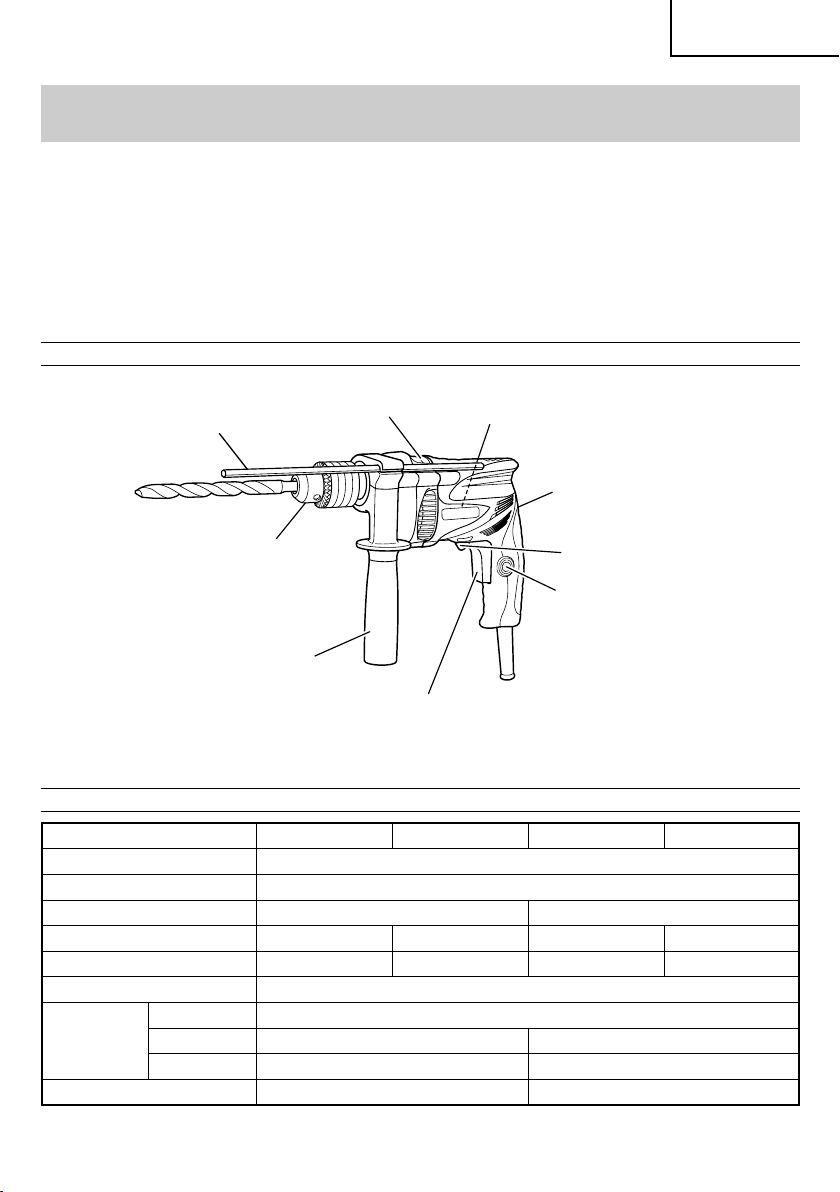
NAME OF PARTS
SPECIFICATIONS
operate, or attempt any maintenance on the tool unless you have first read and understood all
Depth Gauge
Change Lever
Drill Chuck
Side Handle
Switch Trigger
Nameplate
Housing
Rotational change lever
(DV13VSS, DV16VSS only)
Stopper
Fig. 1
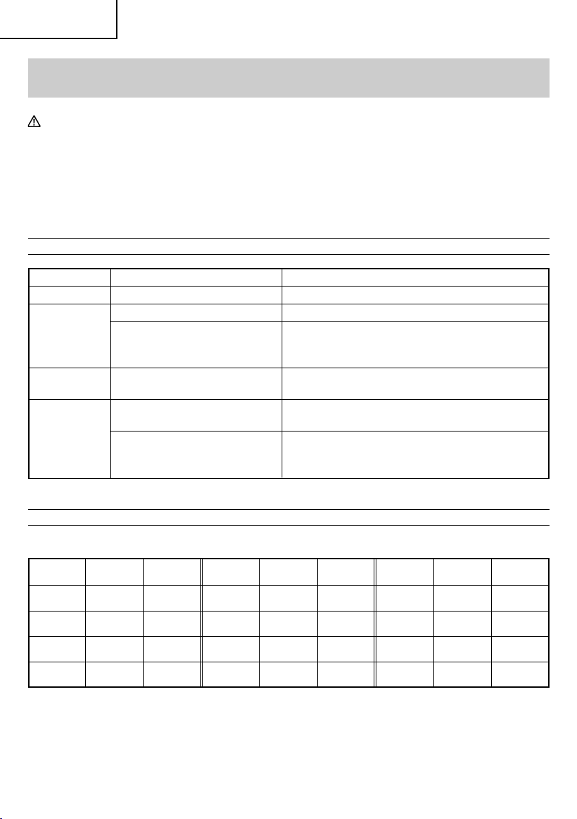
Model DV13SS DV13VSS DV16SS DV16VSS
Motor Single Phase, Series Commutator Motor
Power source Single Phase 120V AC 60 Hz
Current 4.9 A 5.4 A
Reversible None Yes None Yes
No-load speed 2,900/min 0–2,900/min 2,900/min 0–2,900/min
Drill chuck capacity 1/2" (13mm)
Steel 1/2" (13mm)
Capacity Concrete 1/2" (13mm) 5/8" (16mm)
Wood 25/32" (20mm) 1" (25mm)
Weight (Without Cord) 3.1 lbs (1.4 kg) 3.3 lbs (1.5 kg)
7
English
ASSEMBLY AND OPERATION
APPLICATIONS
䡬
By combined actions of ROTATION and IMPACT:
Boring holes in hard surfaces (concrete, marble,
granite, tiles, etc.)
䡬
By ROTATIONAL action:
Boring holes in metal, wood and plastic.
PRIOR TO OPERATION
1. Power source
Ensure that the power source to be utilized
conforms to the power source requirements
specified on the product nameplate.
2. Power switch
Ensure that the switch is in the OFF position. If the
plug is connected to a receptacle while the switch
is in the ON position, the power tool will start
operating immediately and can cause serious
injury.
3. Extension cord
When the work area is far away from the power
source, use an extension cord of sufficient
thickness and rated capacity. The extension cord
should be kept as short as practicable.
WARNING:
Damaged cord must be replaced or
repaired.
䡬
When boring metal or plastic
Use an ordinary metalworking drill bit.
䡬
When boring wood
Use an ordinary woodworking drill bit.
However, when drilling 1/4" (6.5 mm) or smaller
holes, use a metalworking drill bit.
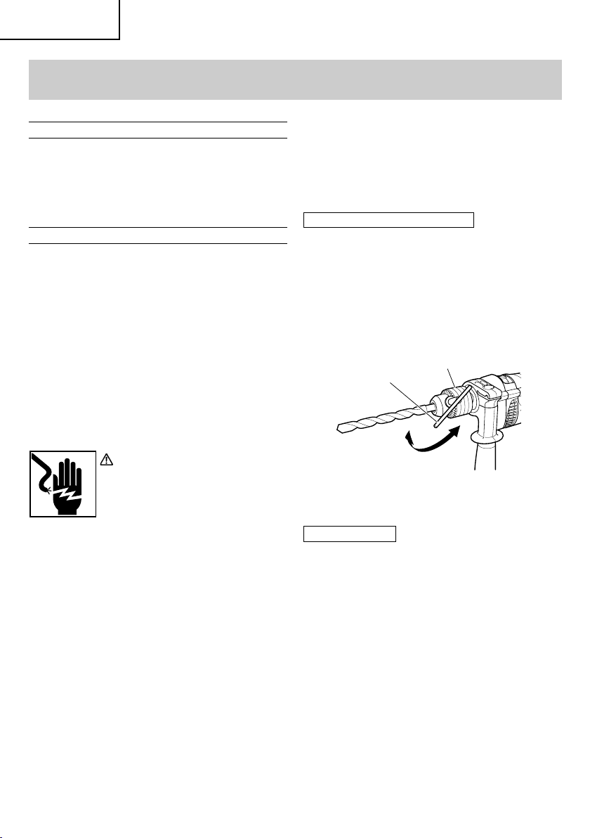
8. Mounting and dismounting of the bit
For Drill chuck with chuck wrench (Fig. 2)
(1) Open the chuck jaws, and insert the bit into the
chuck.
(2) Place the chuck wrench in each of the three holes
in the chuck, and turn it in the clockwise direction
(viewed from the front side). Tighten securely.
(3) To remove the bit, place the chuck wrench into one
of the holes in the chuck and turn it in the
counterclockwise direction.
Chuck
wrench
Tighten
Drill chuck
Loosen
Fig. 2
4. Check the receptacle
If the receptacle only loosely accepts the plug, the
receptacle must be repaired. Contact a licensed
electrician to make appropriate repairs.
If such a faulty receptacle is used, it may cause
overheating, resulting in a serious hazard.
5. Check your work environment
Confirm that the work site is placed under
appropriate conditions conforming to prescribed
precautions.
6. Side handle attachment
Attach the side handle to the mounting part.
Rotate the side handle grip in a clockwise direction
to secure it.
Set the side handle to a position that is suited to
the operation and then securely tighten the side
handle grip.
7. Selecting the appropriate drill bit
䡬
When boring concrete or stone
Use the drill bits specified in the Optional
Accessories.
8
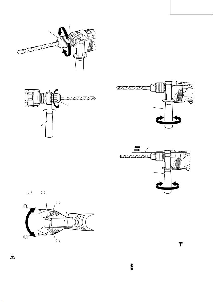
For keyless chuck (Fig. 3)
(1) Open the chuck jaws, and insert the bit into the
chuck.
To open the chuck jaws, hold the retaining ring
while turning the sleeve in the counterclockwise
direction (viewed from the front side).
(2) Firmly grasp the retaining ring and turn the sleeve
in the clockwise direction. Tighten securely.
(3) To remove the bit, firmly grasp the retaining ring
and turn the sleeve in the counterclockwise
direction.
NOTE:
When the sleeve does not become loose any
further, fix the side handle to retaining ring, hold
side handle firmly, then turn the sleeve to loosen
by hand. (Fig. 4)
English
Retaining ringLoosen
Sleeve
10. Fixing the side handle (Fig. 6)
Attach the side handle to the mounting part.
Rotate the side handle grip in a clockwise direction
to secure it.
Set the side handle to a position that is suited to
the operation and then securely tighten the side
handle grip.
To attach a depth gauge on the side handle, insert
Tighten
the gauge into the U-shaped groove on the side
handle, adjust the position of the depth gauge in
accordance with the desired depth of the hole, and
Fig. 3
firmly tighten the side handle grip. (Fig. 7)
Retaining ring
Sleeve
Loosen
Side handle
Fig. 4
9. Check the rotational direction (Fig. 4) (DV13VSS,
DV16VSS only)
The bit rotates clockwise (viewed from the rear
side) by turning the rotational change lever to
R-mark.
The rotational change lever is returned to the
L-mark to turn the bit counterclockwise.
(The L and R marks are provided on the body.)
Rotational change lever
R
mark
Switch trigger
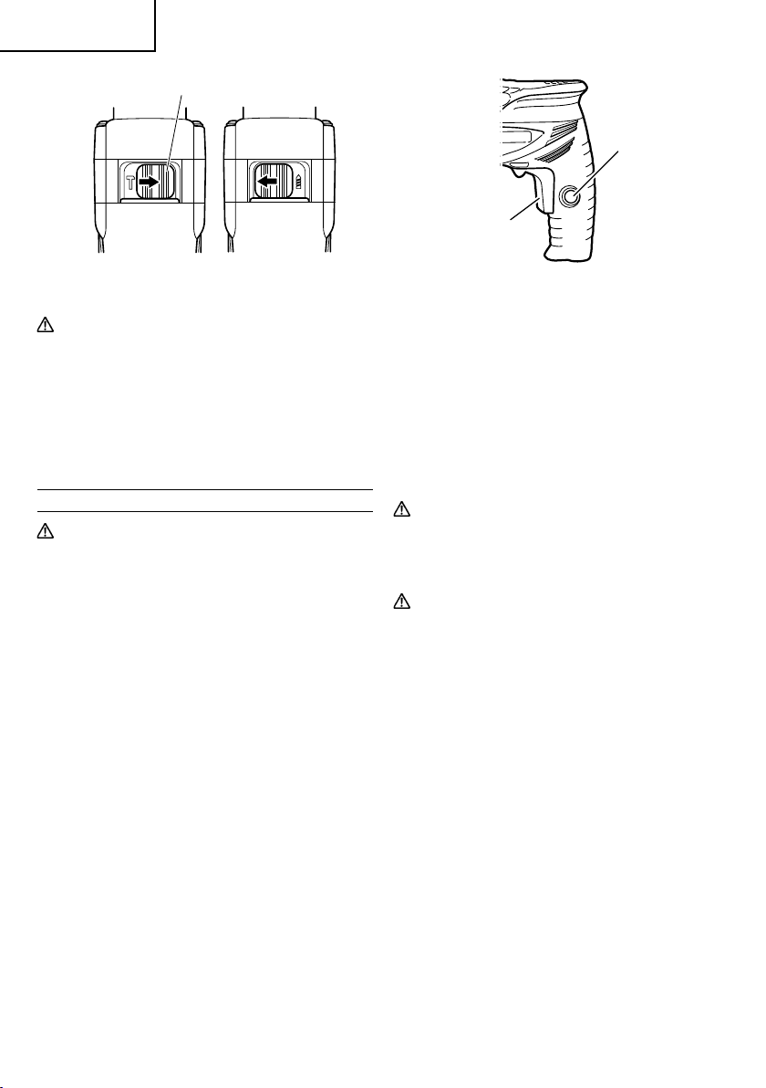
11. IMPACT to ROTATION changeover (Fig. 8)
Shift the change lever between the right and left
positions to switch easily between IMPACT
(rotation and impact) and ROTATION (rotation
only), respectively.
To bore holes in hard materials such as concrete,
L mark
Fig. 5
stone and tiles, shift the change lever to the righthand position (as indicated by the
The drill bit operates by the combined actions of
impact and rotation.
CAUTION:
䢇
Never change the direction of bit rotation while
operating. Turn the power switch OFF before
changing the direction of bit rotation: otherwise,
burning of the motor will result.
䢇
Always use the hammer drill with clockwise
To bore holes in metal, wood and plastic, shift the
change lever to the left-hand position (as indicated
by the mark). The drill bit operates by rotational
action only, as in the case of a conventional electric
drill.
rotation, when using it as an hammer drill.
Side handle
TightenLoosen
Fig. 6
Depth gauge
Side handle
Loosen Tighten
Fig. 7
mark).
9
English
Change lever
Stopper
Impact
Rotation
Fig. 8
CAUTION:
䢇
Do not use the Hammer Drill in the IMPACT
function if the material can be bored by rotation
only. Such action will not only reduce drill
efficiency, but may also damage the drill tip.
䢇
Operating the Hammer Drill with the change lever
in mid-position may result in damage. When
switching, make sure that you shift the change
lever to the correct position.
HOW TO USE
CAUTION:
To prevent accidents, make sure to turn the switch
off and disconnect the plug from the receptacle
when the drill bits and other various parts are
installed or removed. The power switch should
also be turned off during a work break and after
work.
1. Switch operation (Fig. 9)
䡬
When the trigger switch is depressed, the tool
rotates. When the trigger is released, the tool stops.
䡬
Pulling the trigger and pushing the stopper, it keeps
the switched-on condition which is convenient for
continuous running. When switching off, the
stopper can be disconnected by pulling the trigger
again.
< DV13VSS, DV16VSS only >
䡬
The rotational speed of the drill can be controlled
by varying the amount that the Trigger switch is
pulled. Speed is low when the trigger switch is
pulled slightly and increases as the trigger switch
is pulled more.
Switch
trigger
Fig. 9
2. When using as a Drill or a Hammer Drill
(1) Pressing force of the drill
You cannot drill holes more quickly even if you
press the drill with a stronger force than necessary.
It not only damages tip of drill bits and decreases
the efficiency of operation, but also shortens the
life of the drill.
(2) In case of penetrating holes
Drill bits can be broken when the material being
drilled is penetrated. It is important to decrease
pressing force just before penetrating.
CAUTION:
In continuous operation, conduct no-load
operation for five seconds after completing a
drilling job.
WARNING:
When a thick drill bit is used, your arm is subjected
to larger reaction force. Be careful not to be moved
by the reaction force. For this, establish a foothold,
hold the unit tightly with both hands
perpendicularly to the material being drilled.
10

MAINTENANCE AND INSPECTION
English
WARNING:
1. Inspecting the drill bits
Since use of a dull tool will cause motor
malfunctioning and degraded efficiency, replace
the drill bit with a new one or resharpening without
delay when abrasion is noted.
2. Inspecting the screws
Regularly inspect all screws and ensure that they
are fully tightened. Should any of the screws be
loosened, retighten them immediately.
WARNING:
3. Keeping after use
When not in use, the Power tool should be kept in
a dry place out of the reach of children.
4. Inspecting the carbon brushes
For your continued safety and electrical shock
protection, carbon brush inspection and
replacement on this tool should ONLY be
performed by a HITACHI AUTHORIZED SERVICE
CENTER.
5. Maintenance of the motor
The motor unit winding is the very “heart” of the
power tool. Exercise due care to ensure the
winding does not become damaged and/or wet
with oil or water.
6. Service and repairs
All quality power tools will eventually require
servicing or replacement of parts because of wear
from normal use. To assure that only authorized
replacement parts will be used, all service and
repairs must be performed by a HITACHI
AUTHORIZED SERVICE CENTER, ONLY.
7. Service parts list
A: Item No.
B: Code No.
C: No. Used
D: Remarks
Be sure to switch power OFF and disconnect the plug from the receptacle during maintenance
and inspection.
Using this hammer drill with
loosened screws is extremely
dangerous.
CAUTION:
Repair, modification and inspection of Hitachi
●
Power Tools must be carried out by a Hitachi
Authorized Service Center.
This Parts List will be helpful if presented with the
tool to the Hitachi Authorized Service Center when
requesting repair or other maintenance.
In the operation and maintenance of power tools,
the safety regulations and standards prescribed
in each country must be observed.
MODIFICATIONS:
Hitachi Power Tools are constantly being improved
and modified to incorporate the latest
technological advancements.
Accordingly, some parts (i.e. code numbers and/
or design) may be changed without prior notice.
11
English
ACCESSORIES
WARNING:
ALWAYS use Only authorized HITACHI replacement parts and accessories. NEVER use
replacement parts or accessories which are not intended for use with this tool. Contact HITACHI
if you are not sure whether it is safe to use a particular replacement part or accessory with
your tool. The use of any other attachment or accessory can be dangerous and could cause
injury or mechanical damage.
NOTE:
Accessories are subject to change without any obligation on the part of the HITACHI.
STANDARD ACCESSORIES
Model Drill chuck specification Standard accessories
DV13SS Keyed chuck None
Keyed chuck None
DV13VSS
Keyless chuck (2) Depth gauge (Code No. 310331) ............................ 1
(1) Case (Code No. 330702) ......................................... 1
(3) Side handle (Code No. 303659) ............................. 1
DV16SS Keyed chuck
Keyed chuck
DV16VSS
(1) Depth gauge (Code No. 310331) ............................ 1
(2) Side handle (Code No. 303659) ............................. 1
(1) Depth gauge (Code No. 310331) ............................ 1
(2) Side handle (Code No. 303659) ............................. 1
(1) Case (Code No. 330702) ......................................... 1
Keyless chuck (2) Depth gauge (Code No. 310331) ............................ 1
(3) Side handle (Code No. 303659) ............................. 1
OPTIONAL ACCESSORIES...................... sold separately
䡬
Drill bit for concrete and stone
Bit Dia. Overall Code No. Bit Dia. Overall Code No. Bit Dia. Overall Code No.
1/8" 2-9/16"
(3.2mm) (65mm) (8mm) (100mm) (14.3mm) (160mm)
3/16" 3-3/8"
(4.8mm) (85mm) (10mm) (120mm) (16mm) (160mm)
7/32" 4"
(5.5mm) (100mm) (12mm) (120mm)
1/4" 4"
(6.4mm) (100mm) (13mm) (160mm)
Length Length Length
939875
939879
939882
939884
5/16" 4"
3/8" 4-3/4"
15/32" 4-3/4"
1/2" 6-5/16"
931852
931854
971704
931855
9/16" 6-5/16"
5/8" 6-5/16"
931776
931670
NOTE:
Specifications are subject to change without any obligation on the part of the HITACHI.
12
 Loading...