

Hitachi DV 14DSDL, DV 18DSDL Service Manual
LIST No.
DV 14DSDL: J813
DV 18DSDL: J815
Jan. 2012
PRODUCT NAME
Hitachi 14.4 V Cordless Impact Driver Drill
Model DV 14DSDL
Hitachi 18 V Cordless Impact Driver Drill
Model DV 18DSDL
CONTENTS
REPAIR GUIDE ---------------------------------------------------------------------------------------------------------------- 1
1. Precautions on disassembly and reassembly ----------------------------------------------------------- 1
2. Precautions on disassembly and reassembly of battery charger ----------------------------------10
STANDARD REPAIR TIME (UNIT) SCHEDULES ------------------------------------------------------------------- 11
Page
D
DV 18DSDL
International Sales Division

REPAIR GUIDE
Be sure to remove the storage battery from the main body before servicing. Inadvertent triggering of the
switch with the storage battery connected poses the danger of the motor being accidentally turned on.
1. Precautions on disassembly and reassembly
[Bold] numbers in the descriptions below correspond to item numbers in the Parts List and exploded
assembly diagram for the Models DV 14DSDL and DV 18DSDL.
Disassembly
1. Adjust the clutch dial to “ ” with the triangle mark of the main body.
2. Removal of exterior parts
(1) Remove the Truss Hd. Screw M4 (Black) [42]. Remove the Hook [43] for easy disassembly work,
although disassembly can be done without removing the Hook [43].
(2) Remove the four Tapping Screws (W/Sp. Washer) D3 x 20 (Black) [3] from the front side of the body,
and then remove the Cover (A) [4].
(3) First remove the Brush Cap [40], and then use a flat-blade screwdriver to pry off the Carbon Brush 5 x
6 x 11.5 [39] (where the collars are positioned). Be sure to remove the Brush Caps [40] and Carbon
Brushes 5 x 6 x 11.5 [39] on both sides.
3. Disassembly of the main unit
Remove the eleven Tapping Screws (W/Flange) D3 x 16 (Black) [51] from the main unit. While holding the
battery chamber of the Housing (A).(B) Set [41], gently open the Housing (A).(B) Set [41]. The internal
parts can then be removed in the fully assembled state or individually. All parts can be easily removed by
raising Dial Holder (B) [6]. The parts are separated into the drive unit, Click Spring [11], Armature and
Pinion Set [36], Magnet [37], Pushing Button [48], power supply unit, Shift Knob [49], and Strap (Black)
[53].
4. Disassembly of the gear unit
(1) Turn the Motor Spacer [35] counterclockwise (as viewed from the rear of the Armature and Pinion Set
[36]) until a clicking sound is heard, and then remove the Motor Spacer [35] from the Rear Case [21].
(2) Remove the Screw Set D2 x 3.5 (2 pcs.) [23] from the Rear Case [21], and then remove the Shift Arm
[22] from the Gear Box Ass’y [5]. Do not deform the Shift Arm [22] by applying excessive force.
(3) Disassembly of the deceleration mechanism
Turn Washer (B) [34] mounted in the Rear Case [21] counterclockwise to remove it.
Take out the First Ring Gear [33], Planet Gear (A) Set (4 pcs.) [32], Needle Bearing Set (4 pcs.) [31],
Pinion (B) [30], Planet Gear (B) Set (4 pcs.) [26], Pinion (C) [25], and Slide Ring Gear [27] in this order.
Then remove the Screw Set M3 x 12 (4 pcs.) [24] that connects the Front Case [10] and Rear Case
[21]. Take out Washer (A) [20], the Planet Gear (C) Set (5 pcs.) [18], Carrier [17], Ring Gear [19],
Lock Cam [16], Needle Roller Set (6 pcs.) [15], Lock Ring (A) [14], Washer (A) [13], and Pin Set (6
pcs.) [12] from the Front Case [10] in this order.
NOTE: Do not lose any small parts. Pay attention to the Needle Roller Set (6 pcs.) [15] and Pin
Set (6 pcs.) [12] in this operation.
-1-
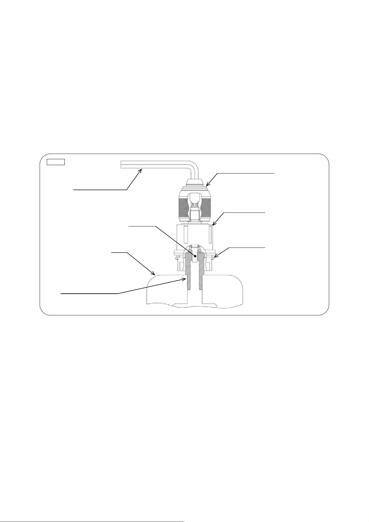
5. Removal of the drill chuck and drive unit
(1) Attach the spindle lock jig (an accessory of special repair tool J-355) to the spindle of Front Case [10],
and then mount it in special repair tool J-355 clamped in the vise as illustrated in Fig. 1.
(2) Turn the sleeve of Drill Chuck 13VLRL-N [2] counterclockwise (as viewed from the front) to fully open
the jaws of Drill Chuck 13VLRL-N [2]. Turn the Flat Hd. Screw (A) (Left Hand) M6 x 25 [1] clockwise
and remove it. (Note that this screw is left-hand threaded.)
(3) Fit the hexagonal bar wrench (M10) into Drill Chuck 13VLRL-N [2] as illustrated in Fig. 1, and then
remove Drill Chuck 13VLRL-N [2] by turning the hexagonal bar wrench counterclockwise.
(4) Remove Dial Holder (B) [6] and the Click Spring [11] from the Front Case [10].
(5) Disassembly of the clutch mechanism
Turn the Nut [7] counterclockwise to remove it from the Front Case [10]. Take out the Spring [8],
Stopper (A) [28], and Stopper Spring [29] in this order.
NOTE: Do not disassemble the Front Case [10].
Fig. 1
Drill Chuck 13VLRL-N [2]
Hexagonal bar wrench
Dial Holder (B) [6]
Spindle
Vise
Special repair tool (J-355)
Front Case [10]
6. Disassembly of the armature unit
(1) Remove the Magnet [37] from the Armature and Pinion Set [36].
Note that the Magnet [37] has strong magnetic force. Hold the Motor Spacer [35] securely and pull it
toward the back of the Armature and Pinion Set [36] to remove.
NOTE: When removing the Magnet [37], note that the ball bearing and washer behind the
Armature and Pinion Set [36] may be attracted to the Magnet [37] and come off the
Armature and Pinion Set [36].
(2) Remove the Motor Spacer [35].
Remove the Motor Spacer [35] from the Armature and Pinion Set [36]. If the Motor Spacer [35] is too
tight to remove, push up the head of the armature shaft in the Armature and Pinion Set [36] while
holding the Motor Spacer [35].
7. Disassembly of the power supply unit
Disconnect the two soldered internal wires (red and black) coming from the Brush Block [38], and the
three soldered internal wires (red, black and white) coming from the Controller Terminal Set [46] from
the DC-Speed Control Switch [50]. The power supply unit can now be disassembled.
-2-
Reassembly
Reassembly can generally be conducted by reversing the disassembly procedure. However, special
attention should be given to the following items.
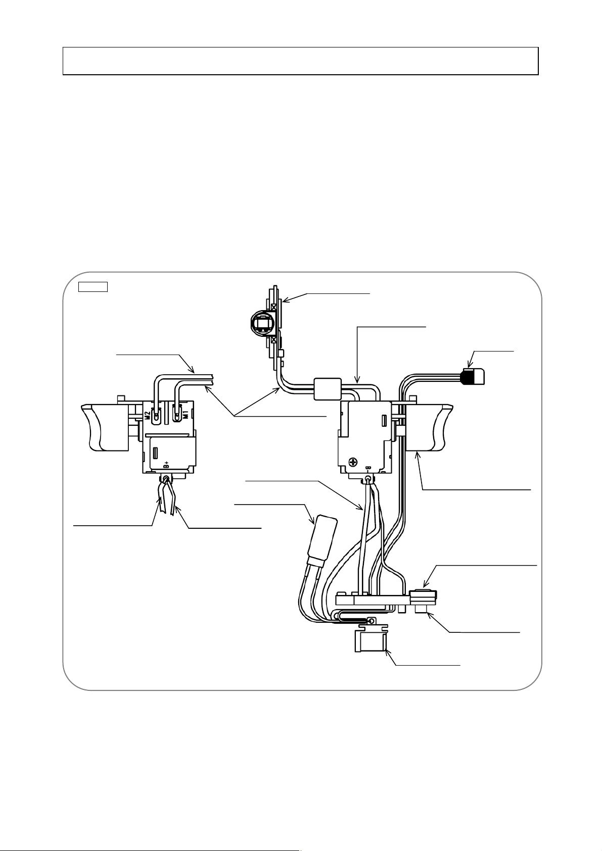
1. Reassembly of the power supply unit
Perform wiring according to the wiring diagram (Fig. 2). Pay attention to the direction in which to connect
the internal wires and terminals.
(1) Solder the internal wire (white) coming from the top of the Controller Terminal Set [46] to the (B-)
terminal of the DC-Speed Control Switch [50]. Then solder the internal wires (brown and red) coming
from the top of the Controller Terminal Set [46] to the (B+) terminal of the DC-Speed Control Switch
[50] (Fig. 2).
(2) Solder the internal wire (red) coming from the Brush Block [38] to the (M2) terminal, and the internal
wire (black) to the (M1) terminal of the DC-Speed Control Switch [50] (Fig. 2).
Fig. 2
Internal wire (red)
Internal wire (brown)
Brush Block [38]
Internal wire (red)
LED light
Internal wire (black)
Internal wire (white)
DC-Speed Control Switch [50]
Noise suppressor
Internal wire (white)
Controller Terminal Set [46]
-3-
Noise suppressor
Terminal support
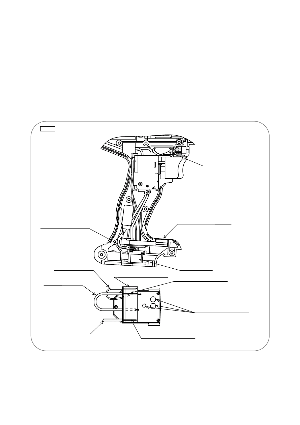
(3) When mounting the DC-Speed Control Switch [50] in housing (A), fit the protrusion of the
forward/reverse changeover lever on top of the DC-Speed Control Switch [50] into the hole groove of
the Pushing Button [48].
(4) Pass the internal wire connected to the LED light between the housing ribs as shown in Fig. 3.
(5) Pass the internal wire connected to the DC-Speed Control Switch [50] between the ribs as shown in
Fig. 3.
(6) Bend the internal wire under the Controller Terminal Set [46] so that it fits in the housing. However, be
careful not to break the internal wire when bending. Do not bend the internal wire toward the noise
suppressor. If the internal wire contacts the noise suppressor, malfunction may be caused (Fig. 3).
NOTE: The contact between the terminal support and battery may be hot when covered with
black metal oxides or when its plating is separated. In extreme cases, the battery and
product may be damaged. Replace the Controller Terminal Set [46] with a new one.
Fig. 3
Pass the internal wire
between the housing ribs.
Pass the internal wire
(brown) between the
housing and the Controller
Terminal Set [46].
Internal wire (white)
Internal wire (black)
Internal wire (brown)
Controller Terminal Set [46]
Terminal support
Terminal support LD terminal
Terminal support (-) terminal
Do not bend the internal wire
toward the noise suppressor.
Terminal support (+) terminal
-4-
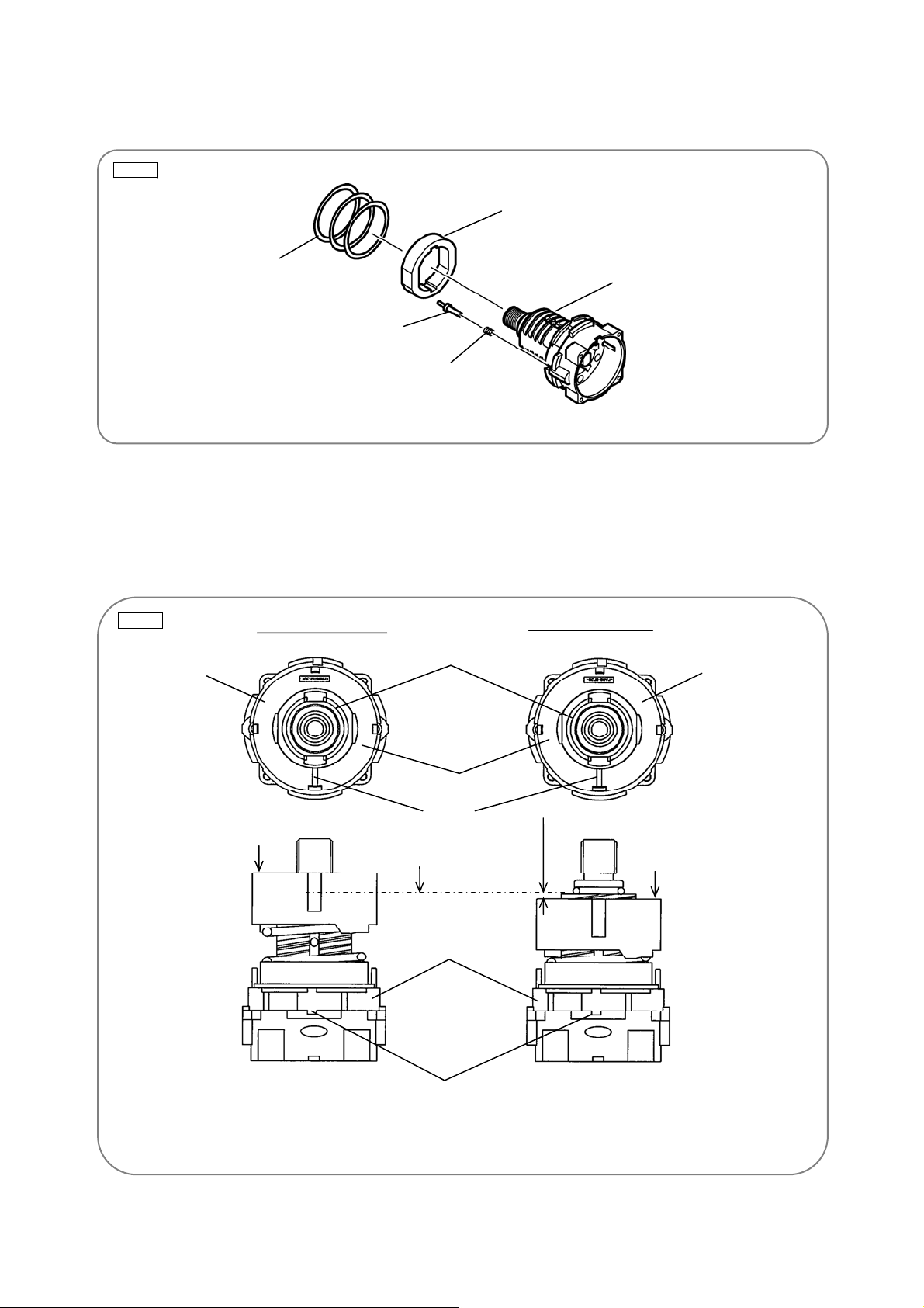
2. Reassembly of the clutch unit
(1) Mount the Stopper Spring [29], Stopper (A) [28], Sleeve [9], and Spring [8] to the Front Case [10] in
this order (Fig. 4).
Fig. 4
(2) Screw the Nut [7] into the Front Case [10] (Fig. 5).
Align mark (i) on the Nut [7] with mark (ii) on the Front Case [10], and then screw in the Nut [7]. Rotate
the Nut [7] about a turn clockwise to align mark (i) on the Nut [7] with mark (ii) on the Front Case [10].
At this time, confirm that the “Y” surface of the Nut [7] is almost flush with the “Z” surface of the Front
Case [10].
Fig. 5
Spring [8]
Screw-in start position
Sleeve [9]
Front Case [10]
Stopper (A) [28]
Stopper Spring [29]
Screw-in end position
Nut [7]
“Y” surface
“Z” surface
“Y” surface
Mark (i)
“Z” surface
Nut [7]
“Y” surface
About 2 mm
Front Case [10]
Mark (ii)
(Axis of Click Spring [11] mount position)
-5-
 Loading...