

Page 1
till!iiCHl ‘
,.
DT3131EUserManual
13.3”SuperTFT ColourLCDMonitor
/“(
Page 2
ENERGY STAR
As an international Energy Star Partner, Hitachi has determined that this product meets
the International Energy Star Programme for energy efficiency.
The International Energy Star Programme is a global programme that promotes energy
saving through the use of computers and other office equipment. The programme backs
the development and dissemination of products with functions that effectively reduce
energy consumption. It is an open system in which business proprietors can participate
voluntarily.
The targeted products are office equipment such as computers, displays, printers,
facsimiles and copiers. Their standards and logos are uniform among participating nations.
MS-DOS and W]ndows are registered trademarks of Microsoft Corporation.
Macintosh is a registered trademark of Apple Computer, Inc.
Other company and product names used herein are the property of their respective
owners.
VESA is an acronym for Video Electronics Standards Association.
DPMS is an acronym for Display Power Management Signaling..
DDC is an acronym for Display Data Channel, a VESA communication standard that
allows monitors to support “Plug & Play” on Windows 95 machines, DDC 1 and DDC
2B refer to two versions of this standard.
NOTICE
No part of this manual maybe reproduced or translated without the written permission of
the publisher.
The contents of this publication are subject to change without prior notice.
Although every precaution has been taken in the preparation of this book, there could be
technical inaccuracies, typographical errors or omissions. We would appreciate your
informing the dealer of any defect found.
Irrespective of the above, we assume no liability for any damages resulting from the use
of the product.
Copyright Cl Hitachi, Ltd. 1996. All rights reserved.
Page 3
CONTENTS
SAFETY PRECAUTIONS
■ General Safety Guidelines
■ Warnings
■ Cautions
E Warning Labels
PREFACE
■ Check List
9 Routine Care
ComEcmG TO THE cOMpUTER
■ Quick-Start Set-up
Z System Set-up
OPERATION
● Controls and Connections
■ On Screen Display (OSD) Overview
■ On Screen Display (OSD) Adjustment
■ Other Features
11
12
15
16
28
18
-.
—.
-.
-—
w
3
4
7
8
9
9
TROUBLESHOOT~G
■ Problem Checklist
29
13MmwfumTEcHNICAL INFOWTION
■ Specifications
■ Video Signal Connections
9 Video Modes
Please read this manual thoroughly, and keep it handy for reference.
Use the product only after reading and understanding the safety precautions
described at the beginning.
31
32
33
1
Page 4
-.
SAFETYPRECAUTIONS
■ GENERAL SAFETY GUIDELINES
Before operating the monitor, read the following instructions carefully
.
Follow all the operating procedures provided in this manual.
.
Pay special attention to and follow all the hazard warnings on the machine and in the
manual. Failure to do so can cause injury to yourself or damage to the machine.
.
Keep in mind that the hazard warnings in this manual or on the machine cannot cover
every possible case as it is impossible topredict andevaluate all circumstances
beforehand. Be aIert and use your common sense.
●
Do not perform any operation or action other than as described in this manual. When
in doubt, call the designated field engineer.
●
The hazard warnings which appear on the safety alert labels on the machine or in the
manual have one OFthe following alert headings consisting of a hazard alert symbol
and a signal word (WARNING or CAUTION).
A WMZNING: Used to indicate a hazard that could result in serious
personal injury or death.
A CAUTION: Used to indicate a hazard that could result in minor
personal injury or serious damage to the product, andlor
adverse effect on adjacent equipment.
-.
w
3
Page 5
■
WARNINGS
Warning: Should something go wrong with the product during operation, stop
A
using it as soon @possible.
Do not leave the product operating if it is producing an odour or smoke. Do not leave
the product operating if malfunctioning, eg no picture on the screen, strange noise.
Failure to do so could cause a fire or electric shock. Immediately turn the power
switch off and unplug the power cord. Make sure the product is no longer producing
au odour, smoke or noise, then contact your dealer or our maintenance staff. Do not
attempt to repair it by yourself as this could be dangerous.
Warning: Do not allow foreign objects inside.
A
Take care not to introduce foreign objects (metals, combustibles, etc.) into the
product through the ventilation holes or elsewhere. Failure to do so could cause a fire
or electric shock.
If anything has entered the product, first turn the power switch off and unplug the
power cord, then inform your dealer or our maintenance staff of the incident. A fire
can occur if you continue using the product with foreign objects left inside.
Warning Do ndt remove the cover.
A
Never attempt to remove the cover of the product. There are high-voltage parts inside
which can cause au electric shock.
A Waruing: Do not try to modify or alter the product.
If you do so it could cause a fire, electric shock, andlor malfunctioning.
A Warning: Do not give the product a physical impact.
If the product has been dropped and/or the case broken, turn the power switch off and
unplug the power cord, then contact your dealer or our maintenance staff. A fire or
electric shock can be caused if you keep using the product after such an impact. When
moving the product, be especially careful to avoid impacts.
A Warning: Do not place the product on an insecure surface.
Set the product on a stable, level surface. If it falls or tips over, it can cause injury.
A Warning: Do not put anything on top of the product.
Keep the top of the product clear of things such as glasses, cosmetics, chemicals,
metals, water containers, and so on. These items or their contents might enter the
product and cause a fiie or electric shock.
Page 6
—.
A Warning: Handle the power cord carefully.
Take care not to damage or break the power cord. Do not apply too much heat, W
pressure or tension to the cord. Avoid bending the cord sharply. Do not attempt to work on the cord. Ignoring this could cause a fue or electric shock.
When connecting and disconnecting the power cord, do it with your hand holding the
power plug. Make sure your hands are dry. Pulling on the cord to disconnect the plug
from the outlet can break the wire. Check the plug to make sure it is sound then insert
the plug firndy until it stops. Avoid using a loose, unsound outlet, or contact failure
can occur. Ignoring this could cause a fire or electric shock.
Disconnect the power cord if the product is not to be used for prolonged periods of
time.
A Warning: Unplug the unit in the event of an electrical storm.
If you hear thunder, turn the power switch off and disconnect the power cord as soon
as possible. Failure to do so could cause a fire, electric shock, or damage to the
product.
A Warning: Use only the specified power voltage.
Do not use any power source other than that indicated. Failure to do so could cause a
fire or electric shock.
A Warning: Do not swallow liquid crystal.
In the event that the LCD panel is broken and liquid crystal flows out, be careful not
to inhale or swallow it. Swallowing this substance can cause poisoning. If it should
enter your mouth, rinse the mouth with water and then consult a doctor.
A Warning: Keep fingers clear of the display when adjusting the screen tilt
When adjusting the screen tilt, take care to avoid catching your fingers between the
screen and the stand.
---
A Warning: Do not put excessive loads on one electrical outlet.
Avoid connecting too many power plugs to a single outlet, thk can cause a fwe. (The
circuit breaker might break the circuit and cut the power to other electrical devices
and appliances.)
A Warning: Life span.
Do not use this monitor for more than its life span (the standard time is 5 years or
P
15,000 hours). This monitor has back lights and electrolytic capacitors which weaken
during the life span of the product. If the monitor fails during this period turn the
power switch off and unplug the power cord, then contact your supplier or authorised
maintenance provider.
5
Page 7
A Warning: FOR CUSTOMERS IN THE UK
THIS PRODUCT IS SUPPLIED WITH A TWO PIN MAINS PLUG FOR USE IN
MAINLAND EUROPE AND A THREE PIN PLUG FOR USE IN THE UK.
PLEASE REFER TO THE NOTES ON THIS PAGE.
IMPORTANT FOR UNITED KINGDOM
The mains lead on this equipment is supplied with a moulded plug incorporating a fuse,
the value of which is indicated on the pin face of the plug. Should the fuse need to be
replaced, an ASTA or BSI approved BS 1362 fuse must be used of the same rating. If the
fuse cover is detachable, never use the phrg with the cover omitted. If a replacement fuse
cover is required, ensure it is of the same colour as that visible on the pin face of the plug.
Fuse covers are available from your dealer.
DO NOT cut off the mains plug from this equipment. If the plug fitted is not suitable for
the power points in your home or office, or the cord is too short to reach a power point,
then obtain an appropriate safety approved extension lead or consult your dealer.
Should it be necessary to change the mains plug, this must be carried out by a competent
person, preferably a qualified electrician.
If there is no alternative to cutting off the mains plug, ensure that you dispose of it
immediately, having first removed the fuse, to avoid a possible shock hazard by
inadvertent connection to the mains supply.
A WARNING: THIS EQUIPMENT MUST BE EARTHED
The wires in the mains lead are coloured in accordance with the following code:
Green and Yellow = Earth Blue= Neutral Brown = Live
As these colours may not correspond with the coloured markings identifying the
terminals in your plug, proceed as follows:
The wire which is coloured GREEN and YELLOW must be connected to the
terminal in the plug which is marked with the letter E or by the earth symbol @ or
coloured GREEN or GREEN and YELLOW.
The wire coloured BLUE must be connected to the terminal marked with the letter N
or coloured BLUE or BLACK.
The wire coloured BROWN must be connected to the terminal marked with the letter
L or coloured BROWN or RED).
6
Page 8
—.
-
■ CAUTIONS
A Caution: Do not block up the vent holes.
The holes are forintemrd hot air to escape tokeepthe product from overheating.
Keep this area free of anything that hinders ventilation. Neglect can be the cause of
internal overheating leading to a fire.
A Caution: Avoid a moist, dusty environment.
Do not use or store the product in a highly humid or dusty place. Doing so could
cause a fiie.
A Caution: Take great care when moving the prodnct.
Before moving the product, be sure tounplug thepower cord and disconnect all
signal cables.
A Caution: Use the product in a place free of corrosive gas and vibration.
Oily soot, corrosive gas or constant vibration can cause the product to malfunction.
A Caution: Do not use the product in a high-temperature environment.
If used exposed to direct sunlight, or placed near a heat source such as a radiator, the
product can malfunction.
A Caution: protect yourself from eY&train.
The eyes become fatigued if you keep watching the monitor for too long a period of
time. Take a break for five to ten minutes after each hour.
A Caution: Be mindful of possible electromagnetic interference.
Electromagnetic interference is likely to occur if the product is used adjacent to other
electronic equipment. It can be the cause of noise and undesired degradation of
electrical performance of nearby radios or TVs.
To eliminate or reduce this effect:
● Place the product away from radios or TVs as far as possible.
● Adjust the direction of the radio or TV antenna.
● Use a separate power outlet.
---
-.
w
A Caution: Pay due attention when disposing of the product.
Mercury is contained in the fluorescent lamp inside the liquid crystal display (LCD).
Do not throw it away with ordinary rubbish. For disposal of the LCD, follow the
appropriate ordinance or regulation of the local government.
A Caution: Be mindful of condensation.
After moving between places with a large temperature difference, use the monitor
only after waiting a while (1 hour). Neglect can be the cause of intemrd overheating
leading to a fiie.
7
Page 9
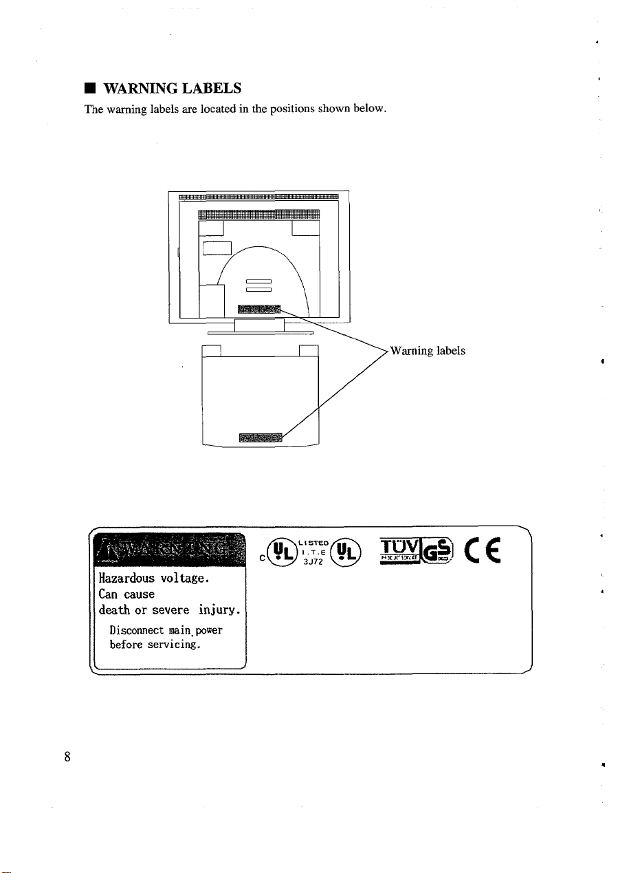
■ WARNING LABELS
The warning labels are located in the positions shown below.
n’
Q
>
Warning labels
l-lazardow voltage.
~ Can cause
death or severe injury.
Disconnect main. power
before servicing.
Page 10
-.
.
-.
PREFACE
Thank you for choosing our Super TFT Colour LCD Monitor. This product is a high
resolution monitor capable of resolutions up to 1024 x 768 dots.
Please read this manual carefully to ensure correct operation,
-–
w
-.
■ CHECK LIST
Before using the product please check the contents of the shipping carton which should
include the following:
● Super TFT Colour LCD Monitor
● Power cord
*User Guide
If any items are missing, or the product is damaged, please contact your supplier
immediately.
■ ROUTINE CARE
When the product is not in use, keep the power cord unplugged and use a dust cover.
.
,
.
Occasionally use a soft, dry cloth to clean the surface of the product. For an extremely
dirty spot or oil stain, use a soft cloth thoroughly wrung out after being soaked in water,
or a neutral detergent to clean the soiled surface. To remove dust, use a dry cloth or an
electric vacuum cleaner. Avoid using thinner, benzene, or similar solvents, or the case
can become deformed and/or discolored. Keep insecticides and other chemicals away
from the product. When cleaning the case take care not to let water or detergent get into
the product. Make sure that the power cord is unplugged before cleaning the product.
.
9
Page 11

CONNECTINGTOTHECOMPUTER
■ QUICK-START SETUP
The DT313 lE’s automatic adjustment feature makes it easy to setup:
1
Before connecting the monitor, check that your computer is setup to use one of the
video modes from Mode 4 and above shown in the table on page 33.
2
Connect the video cable to your computer and switch on the monitor, then the
computer.
3
Select a suitable image for display while auto-adjustment takes place. For example,
maximise Program Manager in Windows 3.1, Explorer in Windows 95/NT or Finder
on a Macintosh.
4
Open the OSD window by pressing the MENU button on the front of the monitor.
Press the SELECT button to select AUTO-ADJUST
5
Press the A button to begin automatic adjustment. The display may appear unclear or
6
distorted while adjustment is in progress. The word “DONE” will appear when
adjustment is completed and the OSD window will return to the main menu.
7
If the image quality is not good, try displaying a different application screen and
repeat again from step 5. If this is still not successful you will need to make manual
adjustments as described on page 16.
8
When you are happy with the display, move the cursor to SAVE SETTINGS and
press the SELECT button. Press the A button to save the new settings. When saving
is completed “DONE” appears and the OSD window closes.
-.
-—
w
The adjustment settings are now saved and will be retained when the monitor is switched
off. Note that you need to make the above adjustment separately for each video mode that
you plan to use.
11
Page 12

■ SYSTEM SET-UP
An example system is shown below. Before making connection, make sure the power
switch is turned off on each unit. The “O’ side of the monitor switch must be pushed.
(Refer to page 15.)
See your computer manual for details of the system unit power switch.
To remove the monitor’s rear cover press both sides of the top edge of the cover and push
down, then pull the bottom edge towards you. To replace it, reverse these steps.
Monitor
1
K
Rear cover
““””
.
,.
Note: This computer system unit is an example only.
12
Ensure correct orientation, then
push the plug onto the connector
until it stops. Turn the screws
clockwise to fasten the connector.
Page 13

—.
—
-.
“.
Do not place the product on an insecure surface.
Be sure to remove the rear cover before connecting and disconnecting the
power cord to and from the monitor. Insert the power plug until it stops with
your hand fiiy holding the plug.
When connecting and disconnecting the power cord to and from the wall
.
outlet, do it with your hand holding the plug. Insert the power plug fdy
until it stops.
Use a proper, safe power outle~ or contact failure could occur.
Do not use any power cord other than the one provided.
,
?
This monitor is ready for use immediately after setting up the computer system. If you
need to adjust the monitor in any way please refer to the OSD (On-Screen Display)
facility.
Please refer to you system manual to set up the computer to a display mode supported by
this monitor. For details check Video Modes on page 33.
.
13
Page 14

OPERATION
■ CONTROLS AND CONNECTIONS
II ’71
-.
w
\
o
n
D
Power
switch
Buttons and Indicators
POWER LED
(green)
n
\\
Power comector
(bottom view)
1
Rear cover
c
Monitor cable
l-l
00
‘000”
SAVE LED (orange)
r
t
BACK button
A button
SELECT button
Page 15

POWER SWITCH
To turn the power on and off, push the “l” and “O” sides respectively. The “POWER’
LED lights to indicate the power is on. (It takes 20 to 30 seconds for the display to be
stable. The back lights may flicker during this time.)
The monitor screen is designed to tilt up to 30 degrees upward and 5 degrees downward.
Choose the angle that suits you best.
LAMPS
● POWER hlp
Indicates that power is ON.
● SAVE hmlp
Glows steadily when the display is in power-save mode (power is ON, but system has
invoked power-save mode or display cable is disconnected). The SAVE lamp blinks
if the display is receiving an inappropriate (unsupported) video signal.
OSD BUTTONS
You use these buttons to adjust the display characteristics as described in the next section.
■ ON-SCREEN DISPLAY (OSD) OVERVIEW
To optimise the display use the on-screen display (OSD) as described below
The display size, image position and brightness depend on the system hardware. Make
screen adjustments after carefully reading this manual. If the screen cannot be adjusted as
desired, refer to your computer system manual to check if the display timing is consistent
with that shown on page 33.
The OSD feature supports the following adjustments:
AUTO-ADJUST: Automatically adjusts H-position, V-position, phase, clock, contrast
and colour balance.
MANUAL ADJUST
H-POSITION: Adjusts the image position horizontally
V-POSITION: Adjusts the image position vertically
PHASE: Fine tunes the display data sample rate
CLOCK: Adjusts the sampling clock to the dot timing of the computer video signal
CONTRAST: Adjusts the contrast
COLOR BALANCE: Adjusts the colour balance
OSD CONTROL: Sets the time that the OSD feature waits before automatically
terminating
OSD COLOR: Selects the OSD window colour from any one of 12 colours
16
.
Page 16

.
SAVE SETTINGS: Saves user settings in the internal non-volatile memory
-.
CLEAR SETTINGS: Restores user settings to the factory default values
BRIGHTNESS: Adjusts the brightness of the backlight
● The OSD feature does not operate if no video signal is present.
● The OSD CONTROL, OSD COLOR and BRIGHTNESS settings affect all display
modes. All other settings apply to the current display mode only.
● If the screen displays the “NOT SUPPORTED’ message your computer may be set to
a video mode that is not supported by the DT3131 E. Please refer to the Video Modes
B
table on page 33. For information on how to make video settings at your computer,
refer to your computer’s operation manual.
P
OSD BUTTONS
The OSD uses a simple menu structure to access the functions. You navigate within the
menus using the buttons on the monitor front panel. The buttons have the following
actions:
● MENU button
Toggles the OSD window on and off. If settings have been changed the SAVE
SETTINGS menu will appear before OSD terminates.
● A and V buttons
These move the cursor between menu items and also increase or decrease selected
values. You can hold the buttons down to produce a continuous increase or decrease.
They are also used to indicate YES (A) and NO (T) in some menus.
When the OSD window is not active pressing either button will open the BRIGHTNESS
menu.
.
● SELECT button
This selects the menu item you have highlighted.
● BACK button
This button moves you back to the previous menu.
.
.
*
17
Page 17

■ ON SCREEN DISPLAY (OSD) ADJUSTMENT
MAIN MENU
To start adjustment press the MENU button. The OSD window opens up at the centre of
the screen and displays the main menu shown below, If you press the MENU button
while the window is open the DT3131 E will either close the OSD window or ask whether
you wish to save your new settings.
The screen displays the current H-SYNC and V-SYNC values and the mode number in
the bottom right corner. The “NOT SUPPORTED’ message will appear if the computer’s
current display mode is not supported. In this case the SAVE lamp will also blink. After
several seconds the display will switch off.
If the “NOT SUPPORTED” message appears your computer may be set to a video mode
that is not supported by the DT3131 E. Please be sure to select a supported mode at your
computer. (Refer to “Video Modes” on page 33). If necessary refer to your computer’s
operation manual for information about how to make video settings at your computer.
If you change one or more values and then press the MENU button to exit the screen will
display the SAVE SETTINGS window. To save settings select YES. For more details
refer to the explanation of the SAVE SETTINGS window (page 26).
18
Page 18

.
—.
AUTO-ADJUST
If you select AUTO-ADJUST from the main menu the foIlowing window appears. You _
can then select whether or not to proceed with automatic adjustment.
-.
w
.
.
Select a suitable image for display while auto-adjustment takes place. For example,
maximise Program Manager in Windows 3.1, Explorer in Windows 95/NT or Finder on
a Macintosh.
During adjustment “DOING’ is displayed and the bar at the bottom tracks the progress.
When adjustment is complete “DONE’ is displayed. The display may become unclear or
distorted while adjustment is in progress. Please do not change your computer’s displaymode settings, switch off the computer’s power or disconnect the display cable while
adjustment is in progress.
If automatic adjustment terminates unsuccessfully “FAILED” will be displayed. If this
occurs press the BACK button to return to the previous screen, and then try automatic
adjustment again. If adjustment fails several times in succession try using manual
adjustment instead.
.
Note that automatic adjustment is available only for video modes 4 through 13 (refer to
“Video Modes” on page 33). In some cases adjustment may produce sub-optimal results
even when carried out as suggested above. If results are imperfect please carry out
manual adjustment as described on the following pages.
19
Page 19

MANUAL ADWST
Automatic adjustment does not always produce perfect results. Some computers have
unusual timing characteristics or other properties that make automatic adjustment
dit%cult. If automatic adjustment is not satisfactory you should proceed to manual
adjustment.
H-POSITION
Adjusts the image position horizontally
20
Page 20

-.
—.
.
V-POSITION
Adjusts the image position vertically
-.
.
.
.
21
Page 21

PHASE
Fine-tunes the display data sample timing
The phase value varies from Oto 63. Try this adjustment if characters appear blurred or if
the screen seems to flicker.
ABC DE FGHI.JK LMNOPQRSTUVWXYZ
ABC DE FGHIJKLMNOPOR ST UVWXYZ
ABC DE FGHIJXLM NO PO RSTUVWXYZ
ABC DE FGHIJKLM NO PO RSTUVWXYZ
Abnormal
Normal
Abnormal
Normal
The usefulness of phase adjustment varies according to the system you are using and the
screen that you are currently displaying, Results may not always be perfect. If the
adjustment does not produce good results try changing to a different screen image or
adjusting the contrast.
Please note that in some rare circumstances when a grey background (made up of
black and white dots) is being displayed, the image may display a pattern of lines.
Even adjusting the PHASE may not remove this and it is suggested that you change
the background from grey to a light colour if possible.
22
,
Page 22

-.
—
CLOCK
Adjusts the sampling clock to the dot timing of the computer video signal
The screen shows the number of sampling pukes per horizontal scan. The default value
varies according to the display mode. You can adjust by up to 32 uuits above or below the
.
default.
A poorly adjusted clock can produce wavy or striped images as illustrated below. If you
see this type of image adjust the clock until the image becomes normal.
-.
.
Stripes
Wavy image
.
,
.
.
,
23
.
Page 23

CONTRAST
Adjusts the contrast
The factory default contrast value is O on a scale from -50 to +50.
COLOR BALANCE
Adjusts the colour balance
Each colour value can be between -32 and +32.
24
Page 24

—.
—.
OSDCONTROL
Sets the time that the OSD feature waits before automatically terminating
The OSD closes if no key is pressed within the specified time and the SAVE SETTINGS
screen does not appem. Note that the new settings are not saved if the OSD function
closes automatically. If you have enabled this feature be sure to save the new settings
promptly.
This setting applies to all display modes.
OSD COLOUR
Selects the OSD window colour from any one of 12 colours
-–.
w
This setting applies to all dkplay modes.
25
Page 25

SAVE SETTINGS
Saves user settings in the internal non-volatile memory
Wlile the settings are being saved “SAVING” is displayed followed by “DONE” when
complete. These settings remain effective until you overwrite them with new settings or
use the CLEAR SETTINGS function to restore factory defaults.
Note that this window automatically appears if you press the MENU button to terminate
OSD adjustment.
Please do not switch off the power while saving is in progress otherwise the display may
not operate correctly the next time you switch on.
CLEAR SETTINGS
Restores user settings to the factory default values
While the settings are being cleared “CLEARING’ is displayed followed by “DONE”
when complete. Note that this operation has no affect on settings for display modes other
than the current one.
26
.
.
.
4
Page 26

—.
.
Please do not switch off the power while clearing is in progress otherwise the display may z“
not operate correctly the next time you switch on.
.
The factory default values are not applied until the power is switched off and on again. -
w
.
BRIGHTNESS
Adjusts the brighmess of the backlight
.
P
.
.
The factory default brightness is 15 on a scale of Oto 31.
When the OSD is not active, pressing the A or V buttons will cause the BRIGHTNESS
Control Screen to appear. You cannot reach this window from the OSD menus.
If you want to save the adjusted brightness value, use SAVE SETTINGS (see page 26).
.
.
.
.
.
.
.
27
‘1
Page 27

H OTHER FEATURES
POWER SAVING FEATURE
The unit incorporates VESA DPMS (Video Electronic Standard Association’s Display
Power Management System) and automatically reduces power consumption when
horizontal and/or vertical synchronisation signals are absent. This is indicated by a bright
SAVE LED located on the right side of the front panel.
Refer to your computer manual for VESA DPMS settings of the computer system unit.
PLUG & PLAY
The DT313 IE supports DDC 1 and DDC 2B (Data Display Channel l/2B) and is
therefore compatible with Windows 95 Plug& Play. For more information about Plug&
Play refer to your system’s user manual.
.
.
.
28
.
Page 28

-.
TROUBLESHOOTING
■ PROBLEM CHECKLIST
If the monitor fails to operate, check the following for problems and their possible causes:
1. No picture
Possible cause Corrective action
Is the computer system unit’s power cord
connected to the mains outlet?
Is the monitor’s power cord connected to
the mains outlet?
Is the monitor’s signal cable properly
connected to the computer system unit?
Is the monitor’s power switch turned on?
Is the system in power saving mode?.
2. Discoloured picture
Possible cause
Is the monitor’s signal cable properly
connected?
Is the system @t set up correctly?
Connect the computer system unit’s
Dower cord to the mains outlet.
Connect the monitor’s power cord to the
mains outlet.
Check that the signal cable is firmly
connected.
Turn the monitor’s power switch on,
(LED indicator lights green.)
Touch the keyboard or mouse to return to
normal mode.
Corrective action
Check that the signal cable is ftiy
connected.
Check the system set up. (See page 12.)
v
3. Displaced display
Possible cause
Is the display position properly adjusted?
If, after checking the above, the monitor still fails to operate, please consult your supplier
or authorised maintenance provider.
Use the OSD facility to correct the
horizontal, vertical positions.
Corrective action
29
Page 29

.
,m
HARDWARETECHNICALINFORMATION
.
-.
—
-.
m
m
.
●
Input signals
Input terminal
Resolutions
.
Display area (mm)
Colonrs
Controls
■
Power management
WincIows95
Operating conditions
Power supply
Power consumption
Dimensions (mm)
Weight
13.3” (338mm)
LCD
Dot pitch (mm): 0.264
Drive system: In-Plane Switching TFT Active Matrix
System
Video; 0.7Vp-p
Sync: Separate, TTL level, non-interlaced
Direct I/F cable with 15-pin D-Sub connector
Horizontal: 1024 dots max.
Vertical: 768 dots max.
X 202.7 (W X H)
270.3
16,190,000
OSD (automatic adjustment, display position, phase,
clock, contrast, colour balance)
Brightness control
VESA DPMS / ENERGY STAR
DDC l/2B Plug& Play
Ambient temperature: 5- 35°C (42 - 95°F)
Humidhy: 20- 80% non-condensing
100- 120V 1200- 240V AC, 50160Hz
Approx 35W
365x 199x 315(WXDXH)
Approx6kg(13.21b) with stand
■ SPECIFICATIONS
Note: Occasionally it may be possible to detect a few dots not working. This is
.
normrd on TFT-LCD monitors and should not be reported as a fault.
.
P
.
31
.
Page 30

H VIDEO SIGNAL
CONNECTIONS
5
00000
(
.
1
.
‘~w~
15-pin mini D-Sub connector
(on the computer system unit)
Pin Signal Name Signal
1 R
2
3
4 NC
5
6
7 G-GND
8
9
10 GND Signal ground
11
12
13 HSYNC
14
15 DDC-C** DDC clock output
G Analogue green output
B
GND Signal ground
R-GND
B-GND Return blue
NC Reserved
NC Reserved
DDC-D* DDC data
VSYNC Vertical sync signal
Analogue red
Analogue blue
Reserved
Return red
Return green
Horizontal sync signal
In/Out
output
output
output
output
output
.
.
.
.
.
* Effective only on systems compliant with DDC 1 or DDC 2B
** Effective only on systems compliant with DDC 2B
32
.
,.
Page 31

—.
—
■ VIDEO MODES
.
This monitor operates in any of the following video modes and can automatically adjust
to modes 4 to 13. Set your computer system to one of the modes listed. See your
-.
-–
computer system manual for details of how to set the video mode.
.
.
.
.
.
,
Model
Display Mode
No.
1
2
3
4
5
6
7
8
9
10
11 1024
12
X 350 (MS-DOS)
640
X 400 (MS-DOS)
640
X 480 (MS-DOS)
640
640 x 480 (Macintosh)
X 600 (VESA)
800
X 600 (VESA)
800
X 600 (VESA)
800
X 600 (VESA)
800
X 600 (VESA)
800
X 768 (WSA)
1024
X 768 (VESA)
X 768 (VESA)
1024
13 1024 x 768 (Macintosh)
Horiz Sweep
Freq (kHz)
31.5
31.5
31.5
35.00
37.9
35.1
37.9
48.1
46.9
48.8
56.5
60.0
60.2
Vert Sweep
Freq (Hz)
70
70
60
67
72
56
60
72
75
“60
70
75
75
)
.
If the screen image is unclear due to an inconsistent display timing, or for any other
reason, use the monitor’s OSD function to make the necessmy adjustments.
When changing the display settings (resolution, numbers of colours, etc), please ensure
.
that the chosen mode is one from the above. If you select a non-supported video mode the
SAVE lamp will begin blinking after a few seconds and the screen may display “NOT
SUPPORTED’, although this may not be readable due to screen instability.
In the 640x 350 and 640x 400 MS-DOS modes, black lines may appem at the top of the
screen and grey lines at the bottom. This is normal and does not indicate a fault.
.
.
.
.
.
.
33
Page 32

Hitachi, Ltd. Tokyo, Japan
International Sales Division
THE HITACHI ATAGO BUILDING,
No. 15 –12 Nishi Shinbashi, 2 – Chome,
Minato – Ku, Tokyo 105-8430, Japan.
Tel: 03 35022111
HITACHI EUROPE LTD. HITACHI EUROPE S.A.
Dukes Meadow 364, Kifissias Ave. & 1, Delfon Str.
Millboard Road 152 33 Chalandri
Bourne End Athens
Buckinghamshire GREECE
SL8 5XF Tel: 1-6837200
UNITED KINGDOM Fax: 1-6835694
Tel: 01628 643000 Email: service.hellas@hitachi-eu.com
Fax: 01628 643400
Email: consumer-service@hitachi-eu.com
HITACHI EUROPE GmbH HITACHI EUROPE S.A.
Munich Office Gran Via Carlos III, 101 - 1
Dornacher Strasse 3 08028 Barcelona
D-85622 Feldkirchen bei München SPAIN
GERMANY Tel: 93 409 2550
Tel: +49 -89-991 80-0 Fax: 93 491 3513
Fax: +49 - 89 - 991 80 -224 Email: rplan@hitachi-eu.com
Hotline: +49 - 180 - 551 25 51 (12ct/min.)
Email: HSE-DUS.Service@Hitachi-eu.com
HITACHI EUROPE AB
HITACHI EUROPE SRL Box 77
Via T. Gulli n.39 S-164 94 KISTA
20147 MILAN SWEDEN
ITALY
Tel: 02 487861 Fax: 08 562 711 11
Fax: 02 48786381
Servizio Clienti
Tel. 02 38073415
Email: customerservice.italy@hitachi-eu.com
HITACHI EUROPE LTD.
HITACHI EUROPE S.A.S Norwegian Branch Office
Lyon Office Strandveien 18
B.P. 45, 69671 Bron Cedex 1366 Dysaker
FRANCE NORWAY
Tel: 04 72 14 29 70 Tel: 02205 9060
Fax: 04 72 14 29 99 Fax: 02205 9061
Email: france.consommateur@hitachi-eu.com Email csgnor@hitachi-eu.com
ITEM N.V./S.A. (INTERNATIONAL TRADE FOR
ELECTRONIC MATERIAL & MEDIA N.V./S.A)
UCO Tower – Bellevue, 17
B – 9050 GENT
BELGIUM (for BENELUX)
Tel: 09 230 48 01
Fax: 09 230 96 80
Email:
www.hitachi-consumer-eu.com
hitachi.item@skynet.be
Tel: 08 562 711 00
Email: csgswe@hitachi-eu.com
 Loading...