

Page 1
HITACHI
DT3130E User Manual
13.3” Super TFT Colour LCD Monitor
Page 2
ENERGY STAR
Asaninternational Energy Star Partner, Hitachi hasdeterrnined that this product meets
the International Energy Star Programme for energy efficiency.
The International Energy Star Programme is a global programme that promotes energy
saving through the use of computers and other office equipment. The programme backs
the development and dissemination of products with functions that effectively reduce
energy consumption. It is an open system in which business proprietors can participate
voluntarily.
The targeted products are office equipment such as computers, displays, printers,
facsimiles and copiers. Their standards and logos are uniform among participating nations.
MS-DOS and Windows are registered trademarks of Microsoft Corporation.
Macintosh is a registered trademark of Apple Computer, Inc.
VESA is an acronym for Video Electronics Standards Association.
DPMS is an acronym for Display Power Management Signaling..
DDC 1 is an acronym for Display Data Channel 1.
NOTICE
No part of this manual maybe reproduced or translated without the written permission of
the publisher.
The contents of this publication are subject to change without prior notice.
Although every precaution has been taken in the preparation of this book, there could be
technical inaccuracies, typographical errors or omissions. We would appreciate your
informing the dealer of any defect found.
Irrespective of the above, we assume no liability for any damages resulting from the use
of the product.
Copyright @Hitachi, Ltd. 1996. All rights reserved.
Page 3
CONTENTS
SAFETY PRECAUTIONS
PREFACE
CONNECTING TO THE COMPUTER
OPERATION
■ General Safety Guidelines
■ Warnings
■ Cautions
w Warning Labels
Check List
9
■ Routine Care
■ System Set-up
■ Controls and Connections
■ On Screen Display Functions
■ Power Saving Feature
-.
3
4
7
8
9
9
11
13
14
22
TROUBLESHOOTING
■ Screen Adjustments
■ Problem Checklist
HARDWARE TECHNICAL
= Specifications
■ Video Signal Connections
B Video Modes
INFOHTION
23
25
27
28
29
Please read this manual thoroughly, and keep it handy for reference.
Use the product only after reading and understanding the safety precautions
described at the beginning.
1
Page 4
SAFETY PRECAUTIONS
GENERAL SAFETY GUIDELINES
■
Before operating the monitor, read the following instructions carefully:
● Follow all the operating procedures provided in this manual.
● Pay special attention to and follow all the hazard warnings on the machine and in the
manual. Failure to do so can cause injury to yourself or damage to the machine.
● Keep in mind that the hazard warnings in this manual or on the machine cannot cover
every possible case as it is impossible to predict and evaluate all circumstances
beforehand. Be alert and use your common sense.
● Do not perform any operation or action other than as described in this manual.
When in doubt, call the designated field engineer.
● The hazard warnings which appear on the safety alert labels on the machine or in
the manual have one of the following alert headings consisting of a hazard alert
symbol and a signal word (WARNING or CAUTION).
A WARNING: Used to indicate a hazard that could result in serious
personal injury or death.
A CAUTION: Used to indicate a hazard that could result in minor
personal injury or serious damage to the product,
andior adverse effect on adjacent equipment.
-–-
m—
v
.
3
Page 5
■ WARNINGS
A Warning: Should something go wrong with the product during operation, stop
using it as soon as possible.
Do not leave the
product operating if it is producing an odour or smoke. Do not leave
the product operating if malfunctioning, eg no picture on the screen, strange noise.
Failure to do so could cause a fire or electric shock. Immediately turn the power
switch off and unplug the power cord. Make
an odour, smoke or noise, then contact your dealer or our maintenance staff. Do not
attempt to repair it by yourself as this could be dangerous.
A Warning: Do not allow foreign objects inside.
Take care not to introduce foreign objects (metals, combustibles, etc.) into the
product through the ventilation holes or elsewhere. Failure to do so could cause a fire
or electric shock,
If anything has entered the product, first turn the power switch off and unplug the
power cord. then inform your dealer or our maintenance staff of the incident. A fire
cao occur if you continue using the product with foreign objects left inside.
A Warning: Do not remove the cover.
Never attempt to remove the cover of the product. There are high-voltage parts inside
which can cause an electric shock.
A Warning: Do not try to modify or alter the product.
If you do so it could cause a fire, electric shock, and/or malfunctioning.
A Warning: Do not give the product a physical impact.
If the product has been dropped and/or the case broken, turn the power switch off and
unplug the power cord, then contact your dealer or our maintenance staff. A fire or
electric shock can be caused if you keep using the product after such an impact. When
moving the product, be especially careful to avoid impacts.
sure the product is no longer producing
■
A Warning: Do not place the product on an insecure surface.
Set the product on a stable, level surface. If it falls or tips over, it can cause injury
A Warning Do not put anything on top of the product.
Keep the top of the product clear of things such as glasses, cosmetics, chemicals,
metals, water containers, and so on. These items or their contents might enter the
product and cause a fire or electric shock.
Page 6
1.
-.
A Warning: Handle the power cord carefully.
Take care not to damage or break the power cord. Do not apply too much heat,
pressure or tension to the cord. Avoid bending the cord sharply. Do not attempt to
work on the cord. Ignoring this could cause a fire or electric shock.
b
r
.
L
When connecting and disconnecting the power cord, do it with your hand holdlng the
power plug. Make sure your hands are dry. Pulling on the cord to discomect the plug
from the outlet can break the wire. Check the plug to make sure it is sound then insert
the plug firmly until it stops. Avoid using a loose, unsound outlet, or contact failure
can occur. Ignoring this could cause a fire or electric shock.
Disconnect the power cord if the product is not to be used for prolonged periods of
time.
A Warning: Unplug the unit in the event of an e]ectricd storm.
If you hear thunder, turn the power switch off and disconnect the power cord as soon
as possible. Failure to do so could cause a fire, electric shock, or darnage to the
product.
A Warning: Use only the specified power voltage.
Do not use any power source other than that indicated. Failure to do so could cause a
fire or electric shock.
A Warning: Do not swallow liquid crystal.
In the event that the LCD panel is broken and liquid crystal flows out, be careful not
to inhale or swallow it. Swallowing this substance can cause poisoning. If it should
enter your mouth, rinse the mouth with water and then consult a doctor.
A Warning: Do not put excessive loads on one electrical outlet.
Avoid connecting too many power plugs to a single outlet, this can cause a fwe. (The
circuit breaker might break the circuit and cut the power to other electrical devices
and appliances.)
A Warning: Life span.
Do not use this monitor for more than its life span (the standard time is 5 years or
15,000 hours). This monitor has back lights and electrolytic capacitors which weaken
during the life span of the product. If the monitor fails during this period turn the
power switch off and unplug the power cord, then contact your supplier or authorised
maintenance provider.
5
Page 7
A Warning: FOR CUSTOMERS IN THE UK
THIS PRODUCT IS SUPPLIED WITH A TWO PIN MAINS PLUG FOR USE IN
MAINLAND EUROPE. FOR THE UK PLEASE REFER TO THE NOTES ON
THIS PAGE
IMPORTANT FOR UNITED KINGDOM
The mains lead on this equipment is supplied with a moulded plug incorporating a fuse,
the value of which is indicated on the pin face of the plug. Should the fuse need to be
replaced, an ASTA or BSI approved BS 1362 fuse must be used of the same rating. If the
fuse cover is detachable, never use the plug with the cover omitted. If a replacement fuse
cover is required, ensure it is of the same colour as that visible on the pin face of the plug.
Fuse covers are available from your dealer.
DO NOT cut off the mains plug from this equipment. If the plug fitted is not suitable for
the power points in your home or office, or the cord is too short to reach a power point,
then obtain an appropriate safety approved extension lead or consult your dealer. “
Should it be necessary to change the mains plug, this must be carried out by a competent
person, preferably a qualified electrician.
If there is no alternative to cutting off the mains plug, ensure that you dispose of it
immediately, having first removed the fuse, to avoid a possible shock hazard by
inadvertent connection to the mains supply.
A WARNING: THIS EQUIPMENT MUST BE EARTHED
The wires in the mains lead are coloured in accordance with the following code:
Green and Yellow = Earth Blue = Neutral Brown = Live
As these colours may not correspond with the coloured markings identifying the
terminals in your plug, proceed as follows:
The wire which is coloured GREEN and YELLOW must be connected to the
terminal in the plug which is marked with the letter E or by the earth symbol @ or
colonred GREEN or GREEN and YELLOW.
The wire coloured BLUE must be connected to the terminal marked with the letter N
or coloured BLUE or BLACK.
The wire coloured BROWN must be connected to the terminal marked with the letter
L or coloured BROWN or RED).
,
.
Page 8
-.
-.
CAUTIONS
■
-.
w
A Caution: Do not block up the vent holes.
The holes are for internal hot air to escape to keep the product from overheating.
Keep this area free of anything that hinders ventilation. Neglect can be the cause of
internal overheating leading to a fire.
A Caution: Avoid a moist, dusty environment.
Do not use or store the product in a highly humid or dusty place. Doing so could
cause a ilre.
A Caution: Take great care when moving the product.
Before moving the product, be sure to unplug the power cord and disconnect all
signal cables.
A Caution: Use the product in a place free of corrosive gas and vibration.
Oily soot, corrosive gas or constant vibration can cause the product to malfunction.
A Caution: Do not use the product in a high-temperature environment.
If used exposed to direct sunlight, or placed near a heat source such as a radiator, the
product can malfunction.
A Caution: protect yourseti from eyestrain.
The eyes become fatigued if you keep watching the monitor for too long a period of
b
time. Take a break for five to ten minutes after each hour.
A Caution: Be mindful of possible electromagnetic interference.
Electromagnetic interference is likely to occur if the product is used adjacent to other
electronic equipment. It can be the cause of noise and undesired degradation of
electrical performance of nearby radios or TVs.
To eliminate or reduce this effect:
● Place the product away from radios or TVs as far as possible.
● Adjust the direction of the radio or TV antenna.
● Use a separate power outlet.
A Caution: Pay due attention when disposing of the product.
Mercury is contained in the fluorescent lamp inside the liquid crystal display (LCD).
Do not throw it away with ordinary rubbish. For disposal of the LCD, follow the
appropriate ordinance or regulation of the local government.
A Caution: Be mindful of condensation.
After moving between places with a large temperature difference, use the monitor
only after waiting a while (1 hour). Neglect can be the cause of internal overheating
leading to a fire.
7
Page 9
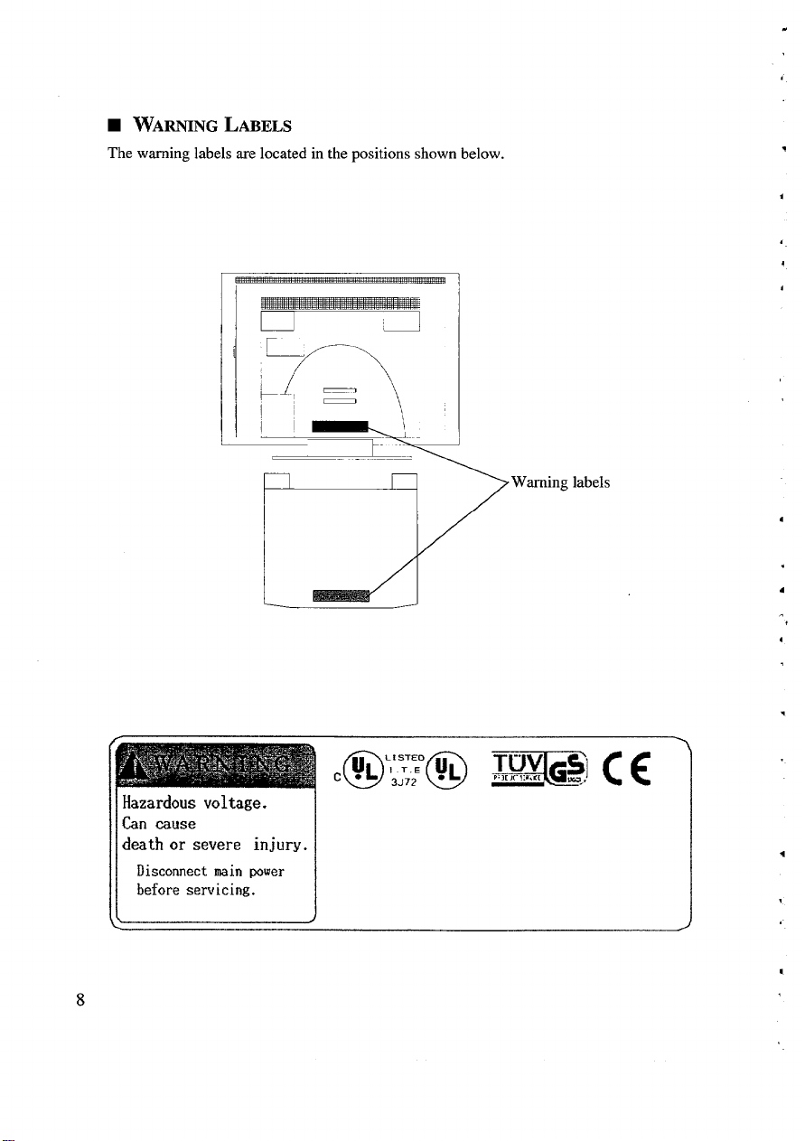
WARNING LABELS
■
The warning labels are located in the positions shown below.
—
I
‘/
—
.
\
/“”
,
.
Hazardous voltage.
Can cause
death or severe injury.
Disconnect main power
before servicing.
.
4
.
Page 10

-.
-.
PREFACE
Thank you forchoosing our Super TFTColour LCD Monitor. This product is a high
resolution monitor capable ofresolutions up to 1024 x768 dots.
Please read this manual carefully to ensure correct operation.
■ CHECK LIST
Before using the product please check the contents of the shipping carton which should
include the following:
● Super TFT Colour LCD Monitor
● Power cord
● User Guide
If any items are missing, or the product is damaged, please contact your supplier
immediately.
■ ROUTINE CARE
b
When the product is not in use, keep the power cord unplugged and use a dust cover.
Occasionally use a soft, dry cloth to clean the surface of the product. For an extremely
dirty spot or oil stain, use a sofi cloth thoroughly wrung out after being soaked in water,
or a neutral detergent to clean the soiled surface. To remove dust, use a dry cloth or an
electric vacuum cleaner. Avoid using thinner, benzene, or similar solvents, or the case
can become deformed and/or discolored. Keep insecticides and other chemicals away
from the product. When cleaning the case, take care not to let water or detergent get into
the product. Make sure that the power cord is unplugged before cleaning the product.
9
Page 11

10
Page 12

.
““””
1
. .
CONNECTING TO THE COMPUTER
■ SYSTEM SET-UP
An example system is shown below. Before making connection, make sure the power
switch is turned off on each unit. The “0’ side of the monitor switch must be pushed.
(Refer to page 13.)
See your computer manual for details of the system unit power switch.
To remove the monitor’s rear cover press both sides of the top edge of the cover and push
down, then pull the bottom edge towards you. To replace it, reverse these steps.
Monitor
I
I
Rear cover
--.
b
Ensure correct orientation, then
push the plug onto the connector
until it stops. Turn the screws
clockwise to fasten the connector.
r
Note: This computer system unit is an example only.
b
“--.-/-’”
11
Page 13

A Warning
Do not place the product on an insecure surface.
.
. Be sure to remove the rear cover before connecting and disconnecting the
power cord to and from the monitor. Insert the power plug until it stops with
your hand firmly holding the plug.
. When connecting and disconnecting the power cord to and from the wall
outlet, do it with your hand holding the plug. Insert
until it stops.
@ Use a proper,
. Do not use any power cord other than the one provided.
This monitor is ready for use immediately after setting up the computer system. If you
need to adjust the monitor in any way please refer to the OSD (On-Screen Display)
facility.
Please refer to you system manual to set up the computer to a display mode supported by
this monitor. For details check Video Modes on page 29.
safe power outlet, or contact failure could occur.
the power plug firmly
12
.
Page 14

.
OPERATION
■
CONTROLS AND CONNECTIONS
.
-—-
.
—...
-Y
F
Rear cover
Monitor cable 0
—
,
k
Power
switch
Buttons and Indicators
-,
,
POWER LED
(green)
P
I
BACK button
Power connector
(bottom view)
MENU
\
MENU button
.
00
‘000”
~
%5VE
SAVE LED (orange)
\
A button
—
I
SELECT button
13
Page 15

To turn the power on and off, push the “l” and “O” sides respectively. The “POWER’
LED lights to indicate the power is on. (It takes 20 to 30 seconds for the display to be
stable. The back lights may flicker during this time.)
The monitor screen is designed to tilt up to 30 degrees upward and 5 degrees downward.
Choose the angle that suits you best.
H ON-SCREEN DISPLAY FUNCTIONS
To optimise the display use the on-screen display (OSD) as described below.
The display size, image position and brightness depend on the system hardware. Make
screen adjustments after carefully reading this manual. If the screen cannot be adjusted as
desired, refer to your computer system manual to check if the display timing is consistent
with that shown on page 29.
Brightness Control
When the OSD is not active, pressing the A or Y buttons will cause the BRIGHTNESS
Control Screen to appear.
BRIGHTNESS Control Screen
● Pressing the A button increases brightness, pressing the V button reduces brightness.
(The factory default brightness is 150nascale of Oto31.) Holding the A or 7
buttons for more than one second will cause the brightness to continue increasing or
decreasing.
● If the MENU button is pressed (or no button pressed for about three seconds) the
original display resumes.
● The SELECT and BACK buttons are not active.
If you want to save the adjusted brightness value, use “SETTING-SAVE’ (see page 20).
14
.
4
Page 16

.
-.
Menu Display
Pressing the MENU button displays the initial MENU screen.
Initial MENU screen
H-POSITION: Adjusts the image position horizontally
V-POSITION: Adjusts the image position vertically
PHASE: Adjusts the phase (to correct blurred or unstable images)
SCALE-PATTERN: Selects the magnification mode
CONTRAST: Adjusts the contrast
CLOCK: Adjusts the dot clock frequency
SETTING-SAVE: Saves user settings in the internal non-volatile memory
SETTING-CLEAR: Restores user settings to the factory default values
-.
● Move to the desired menu item using the A or Y buttons and press the SELECT
button to access the selected item’s sub-menu (adjustment screen).
● Pressing the MENU button returns to the original display.
.f
.
h
15
.
Page 17

H-POSITION
Adjusts the image position horizontally
H-POSITION Control Screen
.
Pressing the A button moves the image to the left, pressing the V button moves it to
the right. Holding the A or 7 buttons for more than one second will cause the position
to continue moving to the left or the right.
.
Pressing the BACK button returns to the MENU.
.
Pressing the MENU button returns to the original display.
.
The SELECT button is not active.
.
F
V-POSITION
Adjusts the image position vertically
16
,.
.
V-POSITION Control Screen
Page 18

.
-.
-.
.
Pressing the A button moves the image up, pressing the 7 button moves it down.
Holding the A or V buttons for more than one second will cause the position to
.
.
b
continue to move up or down.
.
Pressing the BACK button returns to the MENU.
●
Pressing the MENU button returns to the original display.
●
The SELECT button is not active.
PHASE
Fine-tunes the display data sample timing
w
.
,
.
.
Pressing the A button extends the line towards “+”, pressing the T button shortens it
towards “-”. (The phase value on the menu is on a scale from O to 31.) Holding the A
or T buttons for more than one second will cause the value to continue to increase or
decrease.
.
Pressing the BACK button returns to the MENU.
.
Pressing the MENU button returns to the original display.
.
The SELECT button is not active.
Use the PHASE adjustment to remove ripples which may appear on the image.
PHASE Control Screen
17
Page 19

SCALE-PATTERN
Selects the mode in which to magnify the display
SCALE-PATTERN Selection Screen
This function is only valid for video modes displaying fewer than 1024 x 768 pixels,
.
Pressing the A button selects PICTURE MODE, pressing the T button selects
DRAWING MODE.
●
Pressing the BACK button returns to the MENU.
✎
Pressing the MENU button returns to the original display.
✎
The SELECT button is not active.
Selecting the appropriate display mode:
PICTURE MODE: The display is magnified by adding grey scale pixels.
DRAWING MODE:
The display is magnified by adding solid pixels.
.
.
.
In general PICTURE MODE will be appropriate but use DRAWING MODE to get sharp
edges to characters. The following example shows scaling applied to an 800x 600 signal:
Input Signal Picture Mode
X 750 dots
800 x 600 Mode
x
1.25
1000
Drawing Mode
X 750 dots
1000
m
18
d
.
Page 20

CONTRAST
Adjusts the contrast
-.
w
.
.
CONTRAST Adjushent Screen
.
Pressing the A button increases contrast, pressing the T button decreases contrast.
(The factory default value is -1 on a scale from -12to+13.) Holding the A or T
buttons for more than one second will cause the value to continue to increase or
decrease.
.
Pressing the BACK button returns to the MENU.
●
Pressing the MENU button returns to the original display.
✎
The SELECT button is not active.
,
.
19
.
Page 21

CLOCK
Adjusts the sampling clock to the dot timing of the computer video signal
CLOCK Selection Screen
.
Pressing the A
V button decreases the number
for more than one second will cause the value to continue to increase or decrease.
.
Pressing the BACK button returns to the MENU.
.
Pressing the MENU button returns to the original display.
●
The SELECT button is not active.
button increases the number of dots per horizontal sweep, pressing the
of dots per horizontal sweep. Holding the A or T buttons
Use the CLOCK adjustment to remove vertical stripes and/or ripples which may appear
on the image.
SETTING-SAVE
Saves user settings in the internal non-volatile memory
SETTING-SAVE Screen
20
.
.
Page 22

b
.
.
Pressing the A button saves the user settings. While the settings are being saved the
. .
-.
.
-.
P
“SAVING’ is displayed followed by “DONE” when complete.
.
Pressing the BACK button returns to the MENU.
.
Pressing the MENU button returns to the original display.
●
The Y and SELECT buttons are not active.
SETTING-CLEAR
Restores user settings to the factory default values
.
.
SETTING CLEAR Screen
b
* Pressing the A button clears the internal non-volatile memory of user settings and
restores factory default values. While the settings are being cleared “CLEARING’ is
displayed followed by “DONE” when complete.
.
9
● Pressing the BACK button returns to the MENU.
● Pressing the MENU button returns to the original display.
● The 7 and SELECT buttons are not active.
The factory default values are not applied until the power is switched off and on again.
-.
,
B
21
.
Page 23

■ POWER SAVING FEATURE
The unit incorporates VESA DPMS (Video Electronic Standard Association’s Display
Power Management System) and automatically reduces power consumption when
horizontal and/or vertical synchronisation signals are absent. This is indicated by a bright
SAVE LED located on the right side of the front panel.
Refer to your computer manual for VESA DPMS settings of the computer system unit.
.
22
Page 24

TROUBLESHOOTING
SCREEN ADJUSTMENTS
■
Because each computer system can generate video signals with different timings the
monitor may not function correctly when first connected. If this happens make the
suggested adjustments to correct the following conditions:
-.
-.
.
-.
-—
w
Unstable screen (eg displaying
fine checkered patterns)
Text difficult to read
(characters appear blurred)
ABC DE FGHIJKLMNOPOR ST UVWXYZ
ABC DE FGHIJKL MN OPQRSTUVWXYZ
ABC DE FGHIJKL MN OPQRSTUVWXYZ
.
.
Abnormal
,
These conditions can be corrected by adjusting the PHASE as described on page 17.
When the problem has been corrected use the SETTING-SAVE (page 20) function to
Normal
save the new phase setting. If the problem cannot be corrected by adjusting the PHASE,
try adjusting the CLOCK setting first then return to PHASE adjustment.
Please note that in some rare circumstances when a grey background (made up of
black and white dots) is being displayed, the image may display a pattern of lines.
Even adjusting the PHASE may not remove this and it is suggested that you
change the background from grey to a light colour if possible.
Abnorrnrd Normal
.
23
.
Page 25

Vertical lines or stripes
screen
on the
Unsynchronised
screen
.
These conditions can be corrected by adjusting the CLOCK setting as described on page
20. To achieve the most accurate setting display small characters on screen when making
the CLOCK adjustment. When the problem has been corrected use the SETTING-SAVE
(page 20) function to save the new clock setting.
No picture
Check that the monitor is connected to the computer system properly. Refer to
“Connecting to the Computer” (page 11).
If the screen fails to dkplay normally even after making these adjustments, the video
mode being generated by the computer may not be supported by this monitor. Refer to the
computer system manual to check if the display timing is consistent with that shown on
page 29.
,
.
24
Page 26

■
PROBLEM CHECKLIST
If the monitor fails to operate, check the following for problems and their possible causes: -
1. No picture
-.
.
. .
w
Possible cause
,
.
Is the computer system unit’s power cord
connected to the mains outlet?
Is the monitor’s power cord connected to
the mains outlet?
monitor’s signal cable properly
Is the
connected to the comuuter svstem unit?
Is the monitor’s power switch turned on?
.
Is the system in power saving mode?
Connect the computer system unit’s
power cord to the mains outlet.
Connect the monitor’s power cord to the
mains outlet.
Check that the signal cable is firmly
connected.
Turn the monitor’s power switch on.
(LED indicator lights green.)
Touch the keyboard or mouse to return to
normal mode.
Corrective action
.
Discolored picture
2.
Possible cause
Is the monitor’s signal cable properly
connected?
Is the system unit setup correctly?
Check that the signrd cable is firmly
connected.
Check the system set UP. (See Dage 11.)
Corrective action
.
3. Displaced display
Possible cause
●
D
Is the display position properly adjusted?
If, after checking the above, the monitor still fails to operate, please consult your supplier
or authorised maintenance provider.
Use the OSD facility to correct the
horizontal, vertical positions.
Corrective action
25
.
Page 27

-.
HARDWARE TECHNICAL INFORMATION
-.
w
■ SPECIFICATIONS
LCD 13.3”
.
,
Input signrds Video: 0.7Vp-p
Input terminal Direct I/F cable with 15-pin D-Sub connector
Resolutions Horizontal: 1024 dots max.
Display area (mm) 270.3 x 202.7 (W x H)
Controls OSD (display position, phase, magnified display option,
Power management VESA DPMS / ENERGY STAR
Windows95 DDC1
,
Operating conditions Ambient temperature: 5- 35°C
.
.
Power supply
Power consumption Approx 45W
Dimensions (mm) 365 x 199x315 (W x D x H)
Weight Approx 6kg with stand
Dot pitch (mm): 0.088 x 0.264 (H x V)
Drive system: In-Plane Switching TFT Active Matrix
System
Sync: Separate, TTL level
Vertical: 768 dots max.
contrast, clock)
Brightness control
Plug & Play
Humidity: 20- 80% non-condensing
100- 120V / 200- 240V AC, 50/60Hz
,
%
Note: Occasionally it may be possible to detect a few dots not working. This is
normal on TFT-LCD monitors and should not be reported as a fault.
27
,.
Page 28

■ VIDEO SIGNAL CONNECTIONS
15-pin mini D-Sub connector
(on the computer system unit)
Pin
Signal Name Signal In/Out
1 R Analogue red
2
G
Analogue green
3 B Analogue blue
4 NC Reserved
5
6 R-GND
GND Signal ground
Return red
7 G-GND Return green
8 B-GND Return blue
9 NC Reserved
10
11 NC
12 DDC-D*
GND Signal ground
Reserved
DDC data
13 HSYNC Horizontal sync signal
14 VSYNC Vertical sync signal
15
NC Reserved
4
output
output
output
output
output
output
* Valid only for computer systems unit supporting DDC 1
.
Page 29

■ VIDEO MODES
This monitor operates in any of the following video modes. Set your computer system to -
one of the modes listed. See your computer system manual for details of how to set the
k
video mode.
-.
G
—
Model Display Mode Dot Clock Horiz Sweep Vert Sweep
No.
1 640
2 640
3 640
X 350 (MS-DOS}
X 400 (MS-DOS) 25.17 31.47 70.00
X 480 (MS-DOS)
(MHz) Freq (kHz) Freq (Hz)
25.17
31.47 70.00
25.17 31.47 60.00
4 640 x 480 (Macintosh) 30.24 35.00 66.67
.
.
5 800
6
7
8
X 600 (VESA)
X 600 (VESA)
800
X 768 (VESA) 65.00
1024
X 768 (VESA) 75.00 56.48 70.07
1024
36.00 35.15 56.25
40.00
37.89 60.32
48.36
60.00
.
If the screen image is unclear due to an inconsistent dkplay timing, or for any other
reason, use the monitor’s OSD function to make the necessary adjustments.
b
When changing the display settings (resolution, numbers of colours, etc.), please ensure
that the chosen mode is one from the above table otherwise the screen will either display
a distorted image or nothing at all.
In the 640x 350 and 640x 400 MS-DOS modes, black lines may appear at the top of the
screen and grey lines at the bottom. This is normal and does not indicate a fault.
h
29
Page 30

Hitachi, Ltd. Tokyo, Japan
International Sales Division
THE HITACHI ATAGO BUILDING,
No. 15 –12 Nishi Shinbashi, 2 – Chome,
Minato – Ku, Tokyo 105-8430, Japan.
Tel: 03 35022111
HITACHI EUROPE LTD. HITACHI EUROPE S.A.
Dukes Meadow 364, Kifissias Ave. & 1, Delfon Str.
Millboard Road 152 33 Chalandri
Bourne End Athens
Buckinghamshire GREECE
SL8 5XF Tel: 1-6837200
UNITED KINGDOM Fax: 1-6835694
Tel: 01628 643000 Email: service.hellas@hitachi-eu.com
Fax: 01628 643400
Email: consumer-service@hitachi-eu.com
HITACHI EUROPE GmbH HITACHI EUROPE S.A.
Munich Office Gran Via Carlos III, 101 - 1
Dornacher Strasse 3 08028 Barcelona
D-85622 Feldkirchen bei München SPAIN
GERMANY Tel: 93 409 2550
Tel: +49 -89-991 80-0 Fax: 93 491 3513
Fax: +49 - 89 - 991 80 -224 Email: rplan@hitachi-eu.com
Hotline: +49 - 180 - 551 25 51 (12ct/min.)
Email: HSE-DUS.Service@Hitachi-eu.com
HITACHI EUROPE AB
HITACHI EUROPE SRL Box 77
Via T. Gulli n.39 S-164 94 KISTA
20147 MILAN SWEDEN
ITALY
Tel: 02 487861 Fax: 08 562 711 11
Fax: 02 48786381
Servizio Clienti
Tel. 02 38073415
Email: customerservice.italy@hitachi-eu.com
HITACHI EUROPE LTD.
HITACHI EUROPE S.A.S Norwegian Branch Office
Lyon Office Strandveien 18
B.P. 45, 69671 Bron Cedex 1366 Dysaker
FRANCE NORWAY
Tel: 04 72 14 29 70 Tel: 02205 9060
Fax: 04 72 14 29 99 Fax: 02205 9061
Email: france.consommateur@hitachi-eu.com Email csgnor@hitachi-eu.com
ITEM N.V./S.A. (INTERNATIONAL TRADE FOR
ELECTRONIC MATERIAL & MEDIA N.V./S.A)
UCO Tower – Bellevue, 17
B – 9050 GENT
BELGIUM (for BENELUX)
Tel: 09 230 48 01
Fax: 09 230 96 80
Email:
www.hitachi-consumer-eu.com
hitachi.item@skynet.be
Tel: 08 562 711 00
Email: csgswe@hitachi-eu.com
 Loading...