

INSTRUCTION MANUAL
HITACHI Oil-Free Rotary Screw Air Compressor
Air-Cooled
DSP-90A6N DSP-110A6N
DSP-90VA6N DSP-110VA6N
Water-Cooled
DSP-90W6N DSP-110W6N
DSP-90VW6N DSP-110VW6N
Prior to operation of this air compressor,
ensure that all operators read and
understand this INSTRUCTION
MANUAL completely, thereby operating
it safely and properly.
Place the INSTRUCTION MANUAL
near the air compressor to make it
available at any time, and refer to it as
the need arises.
● This INSTRUCTION MANUAL explains in detail
the important items that require attention;
observed as the following:
Always observe Instructions of WARNING,
●
CAUTION
considerable risks to safety.
WARNING
CAUTION
Air-Cooled
Water-Cooled
IMPORTANT
and IMPORTANT, as they indicate
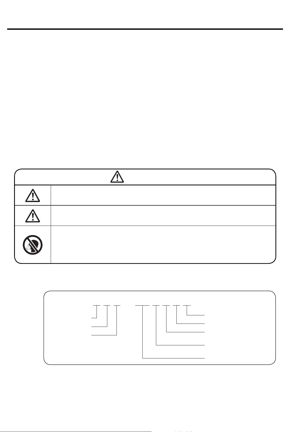
GRAPHIC DESCRIPTIONS:
:Indicates warnings. If handled
improperly, death or severe injury
could result.
:Indicates cautions. If handled
improperly, injury and/or physical
damage could result.
:Indicates air-cooled type.
:Indicates water-cooled type.
:Indicates variable speed type.
:Indicates information that needs
attention, other than WARNING and
CAUTION.
:Indicates a reference page.
How to Use This Instruction Manual
● This Instruction Manual covers the standard models of the Hitachi DSP air compressor.
● This Instruction Manual intended to assist daily operators and maintenance personnel
in the installation, operation, control and service of the air compressor.
● Prior to operation of this air compressor, ensure that all operators read and understand
this INSTRUCTION MANUAL completely, thereby operating it safely and properly.
Place the INSTRUTION MANUAL near the air compressor to make it available at any
time, and refer to it as the need arises.
● If there are any questions or comments, please contact the local Hitachi distributor/
master dealer or representative office.
● Fill your compressor’s model name, Serial Number, etc. in Section 13 of this
Instruction Manual. Such information may be helpful when ordering parts, periodic
maintenance, and overhaul.
■ Model Code
Dry or Oil-Free Rotary
Screw Air Compressor
WARNING
Never remove a protective device from the air compressor or
modify the air compressor.
It is imperative to install an earth leakage (ground) circuit breaker
on the power cable. This prevents a ground fault accident.
DSP air compressors are not designed, intended or approved for
breathing air applications. Hitachi does not approve specialized
equipment for breathing air applications and assumes no responsibility or liability for compressors used for breathing air services.
DSP-90VA6N
NEXTseries
Frequency (5: 50 Hz, 6: 60 Hz)
Packaged
Cooling Method (A: air-cooled ,
W: water-cooled)
V: V type
without V: fixed-speed type
Nominal Output (kW)
● For improvement of the product, contents in this manual are subject to change without notice. Please be forewarned.

Contents
1. SAFETY PRECAUTIONS ………………………………………………………………………………………… 2
2.1 Appearance
2.
GENERAL DESCRIPTION
2.2 Components …………………………………………………………………… 8
2.3 Daily Operating Components ……………………………………………… 10
3.
OPERATING PROCEDURE
3.2 Start/Stop Operation ………………………………………………………… 14
3.3 How to Use the Liquid Crystal Display (LCD)……………………………… 15
3.4 How to Use the Digital Monitor …………………………………………… 25
3.5 Daily Operation of Air Compressor ………………………………………… 32
3.6 Daily Operation of Oil Mist Remover ……………………………………… 34
3.7 Adjusting Procedure…………………………………………………………… 35
3.1 Instrument Panel ……………………………………………………………… 12
4. TROUBLESHOOTING 4.1 Protective Device……………………………………………………………… 36
4.2 Troubleshooting of Air Compressor………………………………………… 38
4.3 Troubleshooting of Oil Mist Remover……………………………………… 39
5.
INSTALLING AND PIPING
5.1 Unpacking the Air Compressor ……………………………………………… 40
THE DSP 5.2 Conveying the Air Compressor ……………………………………………… 40
5.3 Installing the Air Compressor ……………………………………………… 41
5.4 Piping the Air Compressor …………………………………………………… 42
5.5 Ventilation of Air Compressor Room ……………………………………… 45
……………………………………………………………………… 6
6. STARTUP OPERATION 6.1 Startup Operation of the Air Compressor ………………………………… 47
6.2 Initial Setting of OMR Regulator …………………………………………… 50
7. WIRING 7.1 Power Supply Equipment …………………………………………………… 51
7.2 MIV and WIVM Wiring ………………………………………………………… 51
7.3 Connecting the Power Cable ………………………………………………… 52
7.4 Wiring Diagram………………………………………………………………… 54
7.5 Control Panel /LCD monitor Specifications ……………………………… 54
8.
STANDARD COMPONENTS
AND SUBSYSTEMS
8.3 Cooling Water ………………………………………………………………… 66
8.4 Capacity Control System……………………………………………………… 67
8.5 Oil Mist Remover System …………………………………………………… 73
8.2 Air/Oil/Water Flow……………………………………………………………… 61
8.1 Standard Components………………………………………………………… 60
9. MAINTENANCE 9.1 Periodical maintenance of Air compressor………………………………… 74
9.2 Standard Maintenance Schedule …………………………………………… 75
9.3 Maintenance Schedule for Oil Mist Remover……………………………… 79
9.4 How to Service the Air Compressor………………………………………… 80
10. CAUTIONS FOR A LONG TERM OPERATION SUSPENSION…………………………………………… 94
11. PARTS LIST ………………………………………………………………………………………… 95
12. RELOCATION AND 12.1 Relocation…………………………………………………………………… 119
DISPOSAL 12.2 Disposal……………………………………………………………………… 11 9
13. WARRANTY AND 13.1 Warranty……………………………………………………………………… 120
AFTER-SALES SERVICE
13.2 After-Sales Service ………………………………………………………… 120
14. OPERATION RECORD LOGBOOK…………………………………………………………………………… 121
15. STANDARD SPECIFICATIONS………………………………………………………………………………… 122
1

1. SAFETY PRECAUTIONS
013B0816
012B1240012B1240
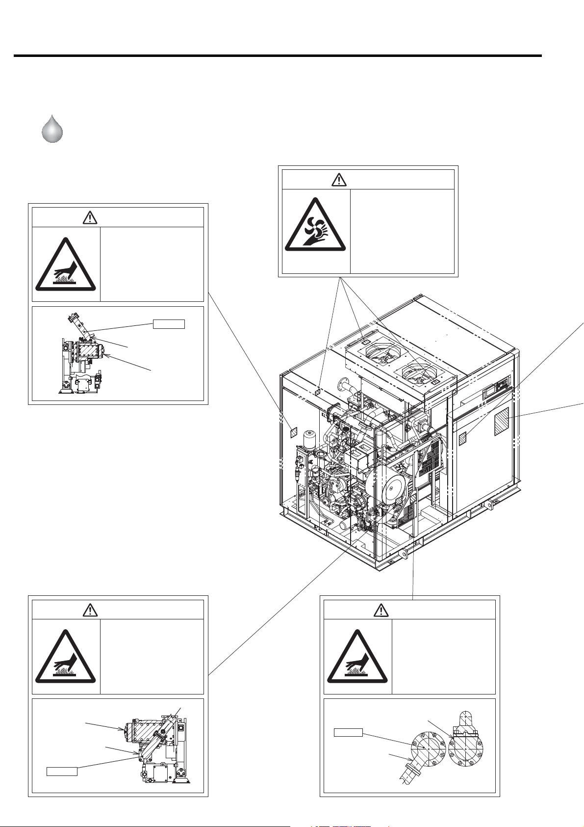
To ensure safe and proper operation of the air compressor, it is indispensable to carefully
read and understand the following warnings and instructions detailed below. These
warnings and instructions are attached to the air compressor as shown in the figure
below.
Air-Cooled
DSP- 90/110A6N
90/110VA6N
WARNING
Hot Surface!
●Do not directly touch any component
inside the air compressor enclosure
when the air compressor is operating
or immediately after it has stopped,
as the components are extremely hot
and can cause severe injury.
●Before servicing the air compressor,
stop it, disconnect the power, then
wait for the air compressor to cool
down.
Heated!!
WARNING
Rotating Parts!
●Keep hands and rods, etc. away from
the rotating parts (Cooling fans, etc.)
●Use caution at all times, when air com-
pressor is powered. The air compressor may be capable of restarting without hitting the START button.
●When the air compressor is operating,
do not remove or open the enclosure
panels and doors.
●
Before servicing the air compressor,
stop it, disconnect the power, especially when accessing any rotating parts.
Discharge Air pipe
Air End
WARNING
Hot Surface!
●Do not directly touch any component
inside the air compressor enclosure
when the air compressor is operating
or immediately after it has stopped,
as the components are extremely hot
and can cause severe injury.
●Before servicing the air compressor,
stop it, disconnect the power, then
wait for the air compressor to cool
down.
Air End
Discharge Air Pipe
Heated!!
2
Aftercooler
Heated!!
Intercooler
1. SAFETY PRECAUTIONS
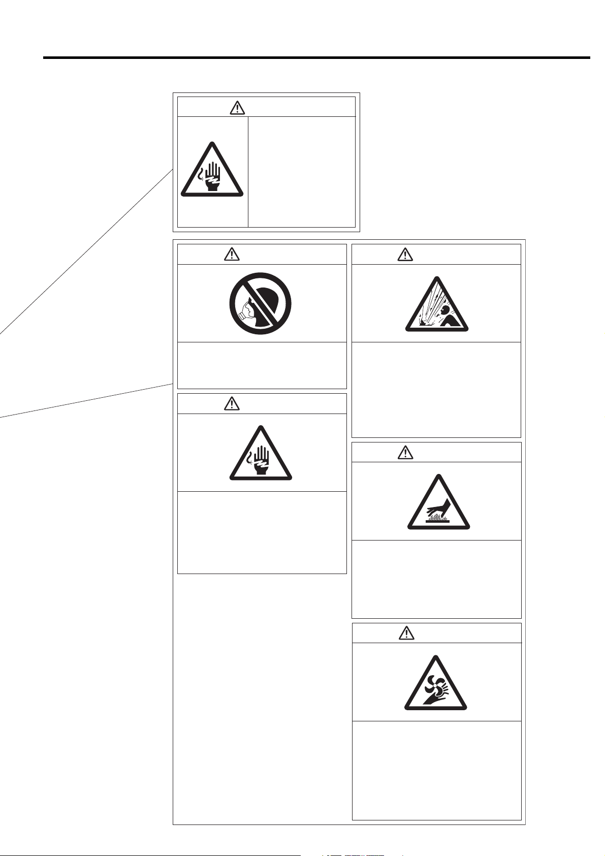
WARNING
Electric Shock Hazard!
●Before servicing or wiring the
air compressor, disconnect
the power. This will prevent
anyone from turning on the
power and causing an electric shock that could lead to
severe injury or death.
●Do not allow any unlicensed
person to wire the air compressor. Always use a licensed
electrician.
●Ground the air compressor.
WARNING WARNING
Do Not Breathe Air!
Discharge air can contain Carbon Monoxide and
other contaminants. Breathing the air can cause
severe injury or death.
WARNING
Electric Shock Hazard!
●
Before servicing or wiring the air compressor,
disconnect the power. This will prevent anyone
from turning on the power and causing an electric
shock that could lead to severe injury or death.
●
Do not allow any unlicensed person to wire the air
compressor. Always use a licensed electrician.
●Ground the air compressor.
●
High pressure air can cause severe injury or death.
Be careful when air compressor is operating.
Pressurized air can blow out of air relief valves and
etc. at incredibly high velocities.
●When using compressed air to clean equipment,
use extreme caution and/or wear eye protection.
●Before servicing the air compressor, stop it,
disconnect the power, and relieve pressure before
removing filter, plug, fitting or cover.
WARNING
High Pressure Air!
Hot Surface!
●Do not directly touch the air end, discharge air
pipe,and coolers when the air compressor is
operating and immediately after it has stopped,
because these parts are heated then.
Before servicing the air compressor (especially
●
when accessing to the heated parts), stop it, disconnect the power, and wait until it is cooled down.
WARNING
●Keep hands and rods, etc. away from the rotating
Rotating Parts!
parts (Cooling fans, etc.)
●Use caution at all times, when air compressor is
powered. The air compressor may be capable of
restarting without hitting the START button.
●When the air compressor is operating, do not
remove or open the enclosure panels and doors.
●Before servicing the air compressor, stop it, dis-
connect the power, especially when accessing
any rotating parts.
3
1. SAFETY PRECAUTIONS
013B0816
012B1240012B1240
Water-Cooled
DSP- 90/110W6N
90/110VW6N
WARNING
Hot Surface!
●Do not directly touch any component
inside the air compressor enclosure
when the air compressor is operating
or immediately after it has stopped,
as the components are extremely hot
and can cause severe injury.
●Before servicing the air compressor,
stop it, disconnect the power, then
wait for the air compressor to cool
down.
Heated!!
Discharge Air pipe
Air End
WARNING
Rotating Parts!
●Keep hands and rods, etc. away from
the rotating parts (Cooling fans, etc.)
●Use caution at all times, when air com-
pressor is powered. The air compressor may be capable of restarting without hitting the START button.
●When the air compressor is operating,
do not remove or open the enclosure
panels and doors.
●
Before servicing the air compressor,
stop it, disconnect the power, especially when accessing any rotating parts.
Air End
Discharge Air Pipe
Heated!!
4
WARNING
Hot Surface!
●Do not directly touch any component
inside the air compressor enclosure
when the air compressor is operating
or immediately after it has stopped,
as the components are extremely hot
and can cause severe injury.
●Before servicing the air compressor,
stop it, disconnect the power, then
wait for the air compressor to cool
down.
Heated!!
Intercooler
WARNING
Hot Surface!
●Do not directly touch any component
inside the air compressor enclosure
when the air compressor is operating
or immediately after it has stopped,
as the components are extremely hot
and can cause severe injury.
●Before servicing the air compressor,
stop it, disconnect the power, then
wait for the air compressor to cool
down.
Aftercooler

1. SAFETY PRECAUTIONS
WARNING
Electric Shock Hazard!
●Before servicing or wiring the
air compressor, disconnect
the power. This will prevent
anyone from turning on the
power and causing an electric shock that could lead to
severe injury or death.
●Do not allow any unlicensed
person to wire the air compressor. Always use a licensed
electrician.
●Ground the air compressor.
WARNING WARNING
Do Not Breathe Air!
Discharge air can contain Carbon Monoxide and
other contaminants. Breathing the air can cause
severe injury or death.
WARNING
Electric Shock Hazard!
●
Before servicing or wiring the air compressor,
disconnect the power. This will prevent anyone
from turning on the power and causing an electric
shock that could lead to severe injury or death.
●
Do not allow any unlicensed person to wire the air
compressor. Always use a licensed electrician.
●Ground the air compressor.
●
High pressure air can cause severe injury or death.
Be careful when air compressor is operating.
Pressurized air can blow out of air relief valves and
etc. at incredibly high velocities.
●When using compressed air to clean equipment,
use extreme caution and/or wear eye protection.
●Before servicing the air compressor, stop it,
disconnect the power, and relieve pressure before
removing filter, plug, fitting or cover.
WARNING
High Pressure Air!
Hot Surface!
●Do not directly touch the air end, discharge air
pipe,and coolers when the air compressor is
operating and immediately after it has stopped,
because these parts are heated then.
Before servicing the air compressor (especially
●
when accessing to the heated parts), stop it, disconnect the power, and wait until it is cooled down.
WARNING
●Keep hands and rods, etc. away from the rotating
Rotating Parts!
parts (Cooling fans, etc.)
●Use caution at all times, when air compressor is
powered. The air compressor may be capable of
restarting without hitting the START button.
●When the air compressor is operating, do not
remove or open the enclosure panels and doors.
●Before servicing the air compressor, stop it, dis-
connect the power, especially when accessing
any rotating parts.
5
2. GENERAL DESCRIPTION
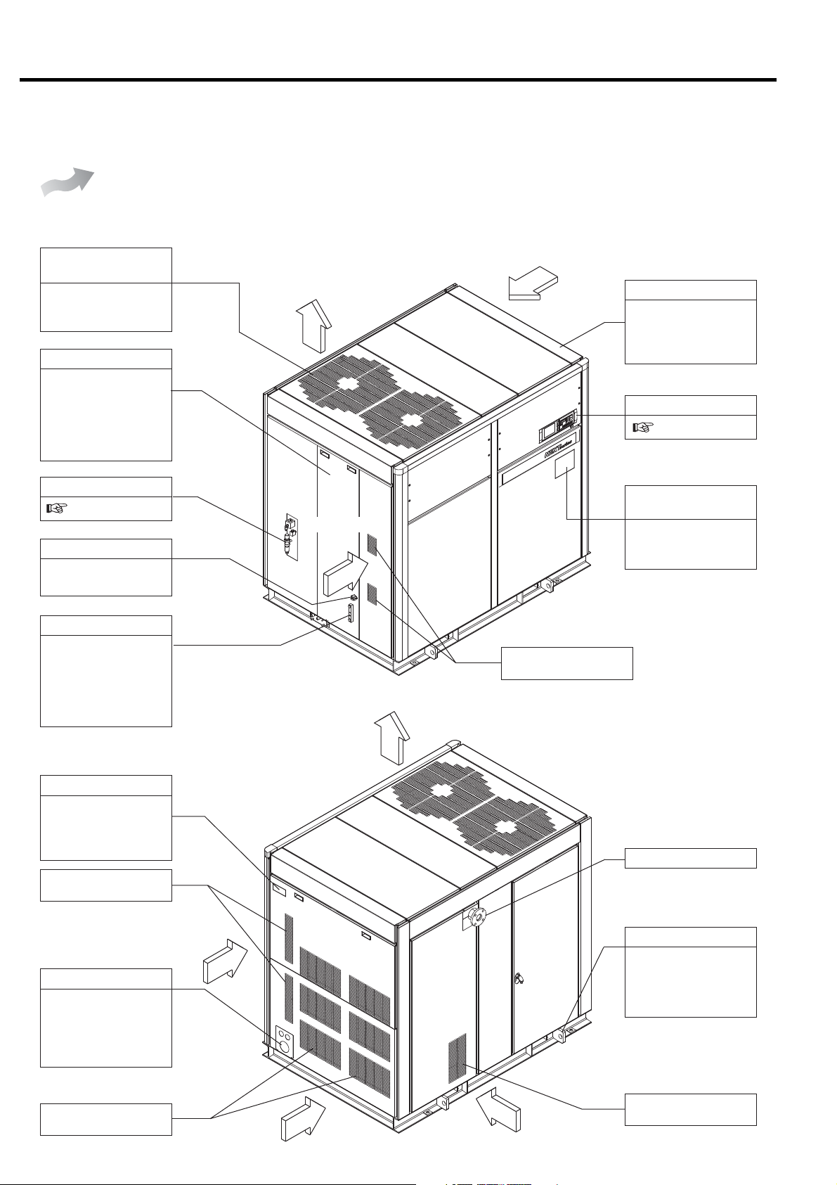
2.1 Appearance
This section illustrates and describes the major components of the DSP air compressor. Be familiar
with the name, location and function of each component before using the DSP air compressor.
Air-Cooled
DSP- 90/110A6N
90/110VA6N
[Front View]
Air Exhaust
(Air Compressor Package)
This panel discharges
the hot air generated
in the air compressor.
Left Door
Open the left door only
when servicing the
DSP air compressor.
Keep it closed when
operating the DSP air
compressor.
OMR
8.5 for the details
Oil Filling Port
Use the port to fill the
gear case with oil.
Air Exhaust
Air Intake
Air Intake
Enclosure
Enclosure panels
lower the sound level
of the air compressor
package.
Instrument Panel
3.1
Plate of Operating /
Servicing Instructions
Read carefully the
plate before operating
and servicing the DSP.
Oil Level Gauge
This indicates the
quantity of the oil in
the gear case. Check
the oil level before
starting the DSP and
when operating it.
[Rear View]
Compressor Name plate
Model designation,
manufacturing number
and specification are
printed.
Air Intake
(Air for inverter)
Air Intake
Power Supply Port
Check the specifications, power supply
and voltage before
connecting the power
supply.
Air Intake
(Inlet to the Air End)
Air Exhaust
Compressed Air Discharge
Sling Fitting
Use the sling fitting
when moving and
installing the DSP air
compressor.
Air Intake
(Air for coolers)
6
Air Intake
Air Intake
Air Intake
(Air Compressor Package)
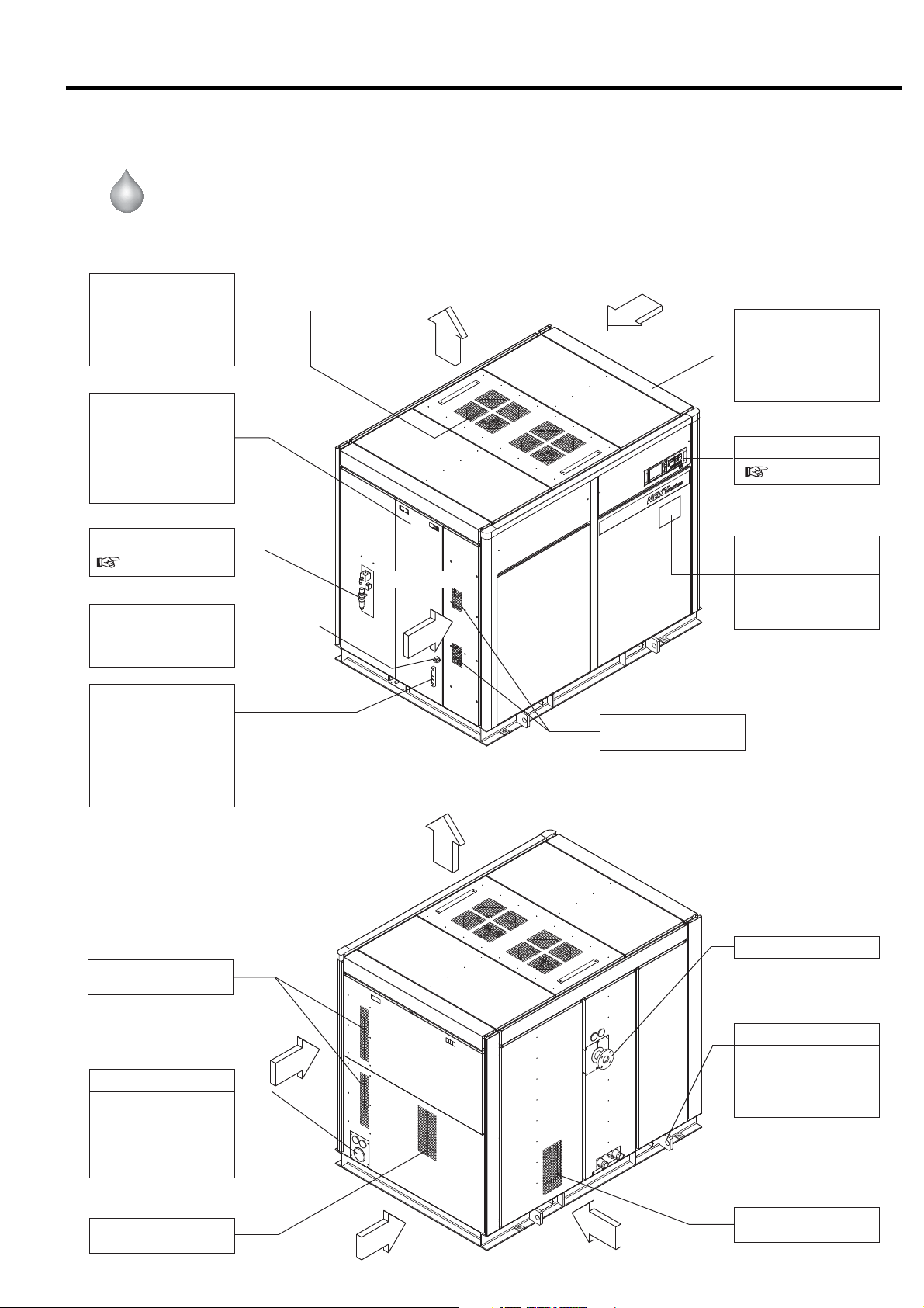
2. GENERAL DESCRIPTION [Appearance]
Water-Cooled
DSP- 90/110W6N
90/110VW6N
[Front View]
Air Exhaust
(Air Compressor Package)
This panel discharges
the hot air generated
in the air compressor.
Left Door
Open the left door
only when servicing
the DSP air compressor. Keep it closed
when operating the
DSP air compressor.
OMR
8.5 for the details
Oil Filling Port
Use the port to fill the
gear case with oil.
Air Exhaust
Air Intake
Air Intake
Enclosure
Enclosure panels
lower the sound level
of the air compressor
package.
Instrument Panel
3.1
Plate of Operating /
Servicing Instructions
Read carefully the
plate before operating
and servicing the DSP.
Oil Level Gauge
This indicates the
quantity of the oil in
the gear case. Check
the oil level before
starting the DSP and
when operating it.
[Rear View]
Air Intake
(Air for inverter)
Air Intake
Power Supply Port
Check the specifications, power supply
and voltage before
connecting the power
supply.
Air Intake
(Inlet to the Air End)
Air Exhaust
Compressed Air Discharge
Sling Fitting
Use the sling fitting
when moving and
installing the DSP air
compressor.
Air Intake
(Air for Package)
Air Intake
Air Intake
Air Intake
(Air Compressor Package)
7
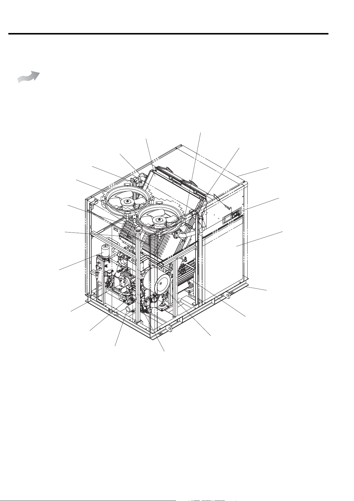
2. GENERAL DESCRIPTION [Components]
2.2 Components
Air-Cooled
Hi-precooler
DSP- 90/110A6N
90/110VA6N
Discharge pipe (Compressed
Air Discharge)
Air relief valve
Cooling fan
Oil cooler
Check valve
Aftercooler
Intercooler
Enclosure
Instrument panel
Control panel
Oil mist remover
2nd-stage air end
1st-stage air end
Common base
Main motor
Air intake filter
Oil filter
Oil level gauge
8
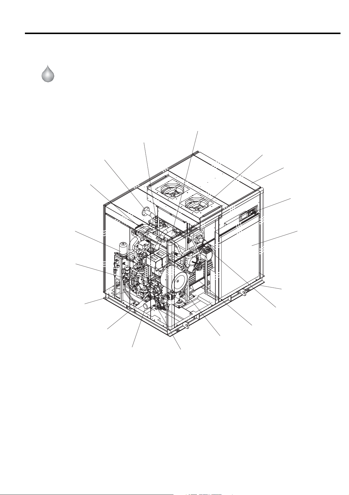
2. GENERAL DESCRIPTION [Components]
Water-Cooled
Oil mist remover
DSP- 90/110W6N
90/110VW6N
Discharge pipe
(Compressed air discharge)
Intercooler
Aftercooler
Air relief valve
Cooling fan
Enclosure
Instrument panel
Control panel
2nd-stage air end
Oil cooler
1st-stage air end
Oil filter
Common base
Check valve
Main motor
Air intake filter
Oil level gauge
9
2. GENERAL DESCRIPTION [Daily Operating Components]
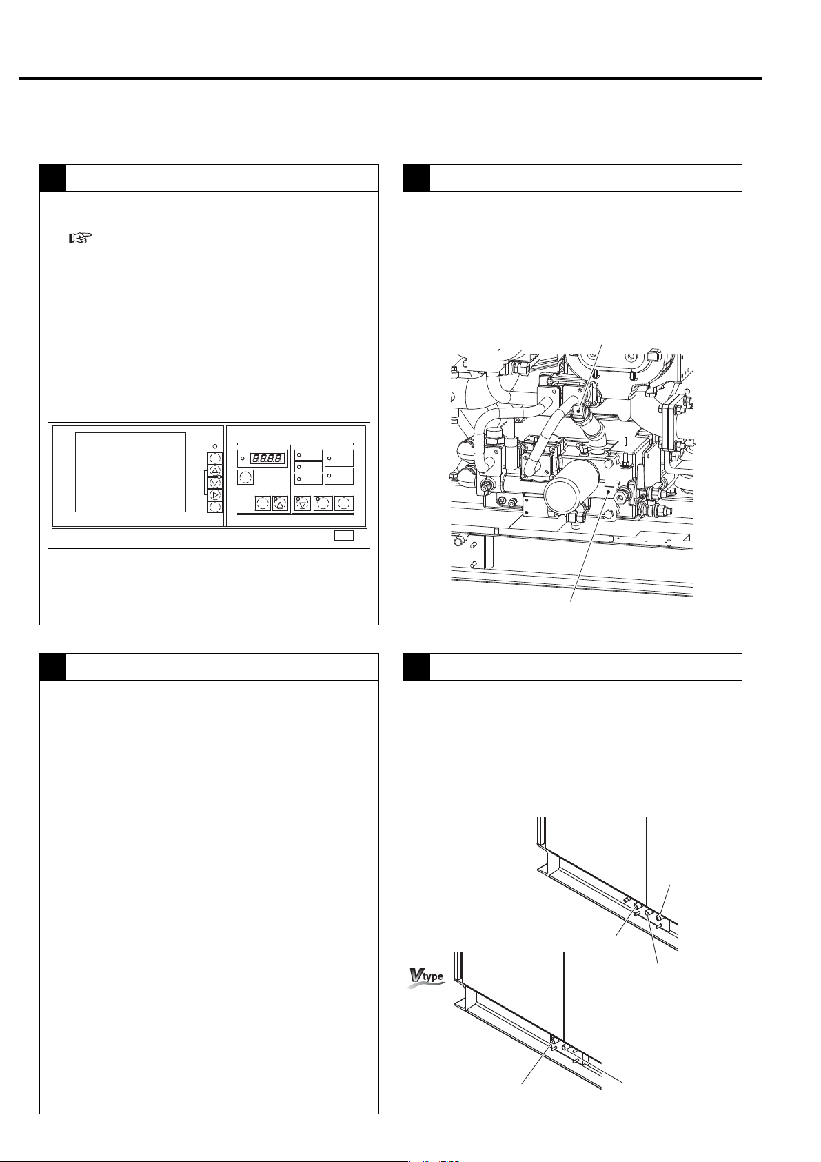
2.3 Daily Operating Components
Controls on the Instrument Panel
1 2
● Indicates the operation control section.
(
3.1)
● Power ON → The Power light ON.
● Start: Press the START button. → Start light ON.
● Stop: Press the UNLOAD STOP button. →
The compressor unloads for 5 minutes and then
stops. → Start light OFF.
● Power OFF: → Power light OFF.
MONITOR
AUTO
MONITOR
MENU
+/−
UP/
DOWN
SET
RUNNINGCONTROL
ALARM
FUNC
RESET
REMOTE
STR
[×10h]
SELECT/WIDE
1
RUNNINGMODE
REMOTE
LOAD
SHUTDOWN
2
START
POWER
AUTOSTART
STOP
UNLOAD STOP
Oil Level Gauge
● Verify that the oil stays between the upper and
lower red lines of the oil level gauge during the
operation.
Oil level might be higher than upper line during air
compressor
and pipings.
stopping due to oil returning from the cooler
Oil Filling Port
Lubricating Oil
3 4
Oil: Use genuine Hitachi GL-68 DSP Compressor Oil.
Replace the oil every 8,000h operating hour or every
2-year, whichever comes earlier.
Oil Level Gauge
Aftercooler and Intercooler - Condensate Drain Valve
● Verify that air containing condensate is discharged
intermittently from the intercooler and aftercooler
drain ports.
The higher temperature and humidity, the more condensate
is produced. Condensate may not be produced on the
intercooler side during winter.
[Fixed speed type]
Control pipe filter
drain port
Intercooler
drain port
Aftercooler
drain port
10
Intercooler
drain port
Aftercooler
drain port

Water-Cooled
2. GENERAL DESCRIPTION [Daily Operating Components]
Cooling Water
5
① Stop the cooling water flow when the DSP has
stopped running.
② Open the water drain peacock and the water drain
valve at the water drain port to remove the cooling
water from the system.
③ Take care to completely drain the cooling water
during the winter season to prevent freezing in the
cooling water pipes (
Water drain peacock
8.3)
Control Line Filter
6
[Fixed speed type]
● Check the sight glass on the control line filter to
make sure that the condensate discharged
properly.
Control line filter
Sight Glass
Water drain port
Stopping operation
7
● Normally use the UNLOAD STOP button to stop
the air compressor. The air compressor then
unloads for 5 minutes and stops running.
(In the case of an emergency, press the
EMERGENCY STOP button to stop operation.)
RUNNINGCONTROL
ALARM
FUNC
RESET
REMOTE
STR
MONITOR
AUTO
MONITOR
MENU
+/−
UP/
DOWN
SET
IMPORTANT
Keeping the second-stage air end as dry as possible
is essential for preventing it from rusting due to a long
term operation suspension. When stopping the DSP,
therefore, execute an unloading operation and thereby
remove the moisture from the second-stage air end.
[×10h]
SELECT/WIDE
1
RUNNINGMODE
REMOTE
LOAD
SHUTDOWN
2
START
POWER
AUTOSTART
STOP
UNLOAD STOP
11
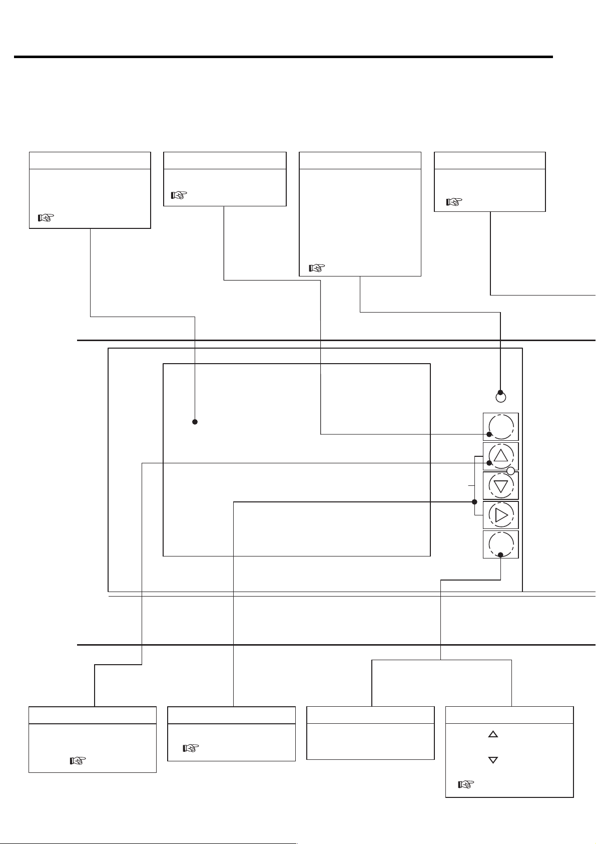
3. OPERATING PROCEDURE
3.1 Instrument Panel
LCD monitor
Displays the operation data,
various settings, shutdown/
alarm information, etc.
( 3.3)
MONITOR Button RESET Button
Switches the monitor display.
( 3.3.1)
AUTO light (yellow)
ON (glowing) when an
automatic operation (an
AUTO operation, a scheduling operation, or lead/lag
operation) is activated.
ON (blinking) when external
calendar or scheduling
operation is abnormal.
( 3.3.3, 3.3.5)
Resets SHUTDOWN
and ALARM screens.
( 3.3.3)
AUTO
MONITOR
MENU Button
Displays the menu screen.
Also used to move the
cursor. ( 3.3.4)
+/- UP DOWN Button
Moves the cursor.
( 3.3.4)
MONITOR
Saves any adjusted set
points.
SET Button
MENU
+/−
UP/
DOWN
SET
Contrast adjustment
SET + [ ] buttons:
Increases brightness.
SET + [] buttons:
Decreases brightness.
( 3.3.6)
12
Digital Monitor
Used for basic settings as well
as other various settings in
combination with the LCD monitor.
( 3.3.6)
● ALARM light (green): Blinks if
an alarm failure occurs.
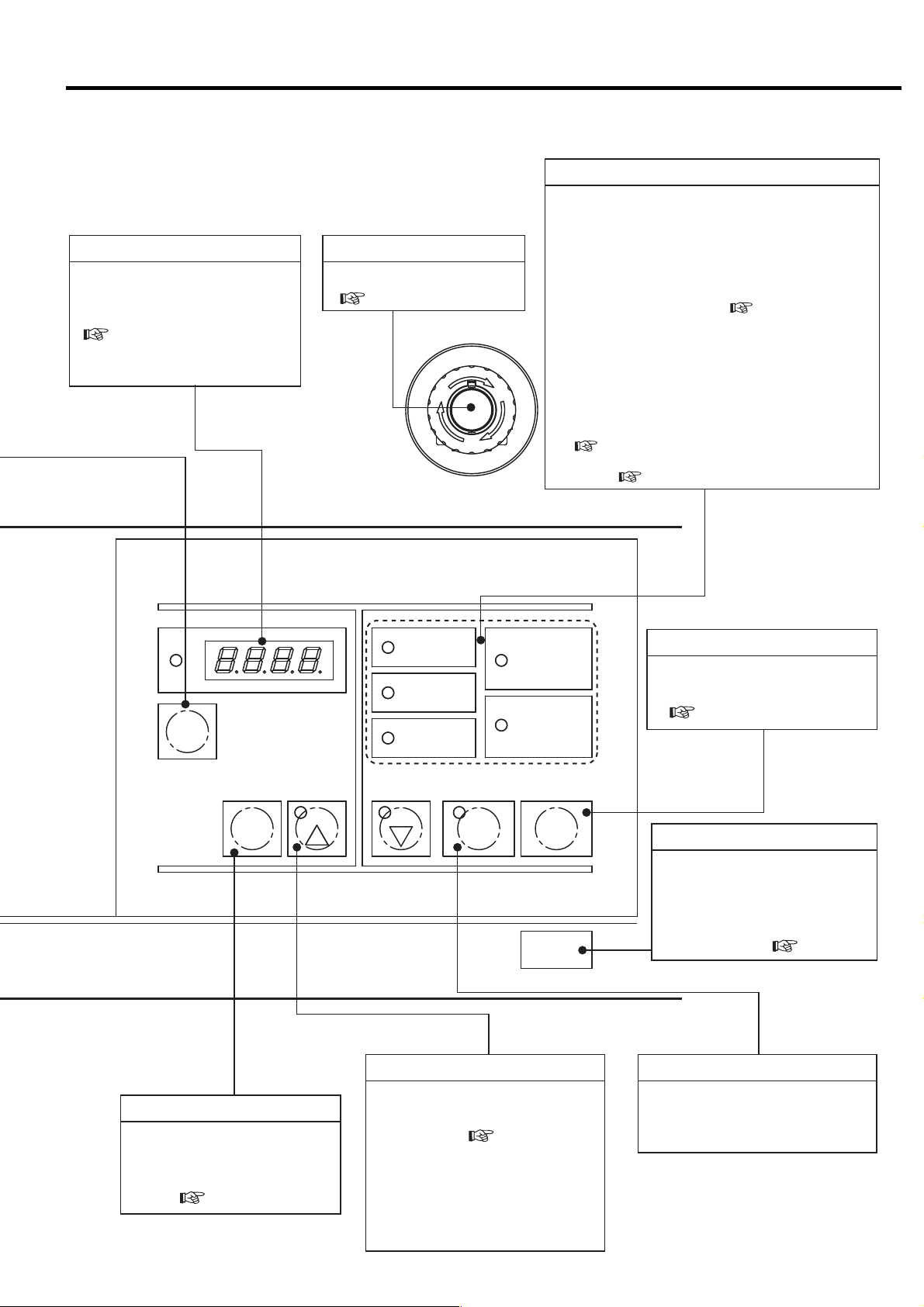
3. OPERATING PROCEDURE [Instrument Panel]
EMERGENCY STOP button
Stops for emergency.
( 3.2.3)
G
E
R
N
E
M
E
S
C
P
T
O
RUNNING MODE Light
● POWER light (yellow): Lights up when the main power
is turned on.
● REMOTE light (green):
ON (glowing) when the REMOTE button is pressed in
order to activate a remote operation.
ON (blinking) when an external remote-operation-
activation switch has been turned on in order to
activate a remote operation. ( 3.4.6)
● LOAD light (yellow): ON (glowing) when the air
compressor is loading.
● AUTO START light (green):
ON (glowing) while the air compressor is in a stop due
Y
to an AUTO operation,lead/lag operation, or
scheduling operation.
ON (blinking) while the air compressor is in a stop due
to a restartable instantaneous power interruption.
( 3.3.3)
● SHUTDOWN light (red): Blinks if a shutdown failure
occurs. ( 3.3.3)
RUNNINGCONTROL
REMOTE
ALARM
[×10h]
FUNC
Press this button to stop the air compressor.
The air compressor will stop after removing the
condensate from the air end.
※This stop button is effective while a stand alone operation.
RESET
REMOTE
STR
SELECT/WIDE
1
LOAD
SHUTDOWN
2
RUNNINGMODE
POWER
AUTOSTART
START
UNLOAD STOP
STOP Button
Stops the compressor
immediately without unloading.
( 3.2.2)
STOP
UNLOAD STOP Button
Stops the compressor in normal
state.
The compressor stops running
after removing the condensate
from the air end. ( 3.2.2)
REMOTE Button
Activates or deactivates a
remote start/stop operation
locally or on the instrument
panel. ( 3.4.6).
SELECT/WIDE Button/Light (Yellow)
Press to confirm the measurement
values, shutdown history, and
setting status. ( 3.4.1, 3.4.2)
To set the ECOMODE [Energy
saving mode] (Fixed speed type
only), hold down the
SELECT/WIDE
button for at least 7 seconds. The
light blinks and ECOMODE is set.
START Button
Starts the air compressor.
The START light turns ON while
air compressor is running.
13
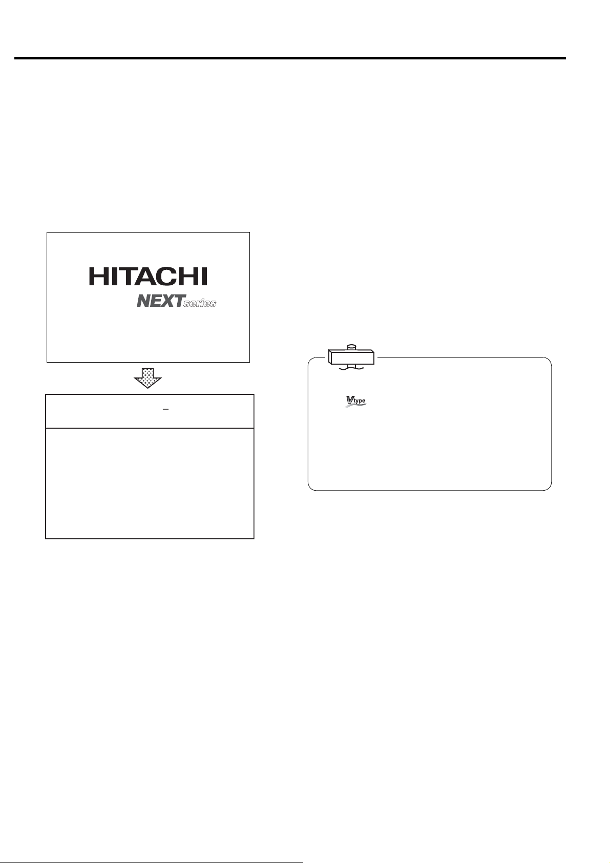
3. OPERATING PROCEDURE [Start/Stop Operation]
3.2 Start/Stop Operation
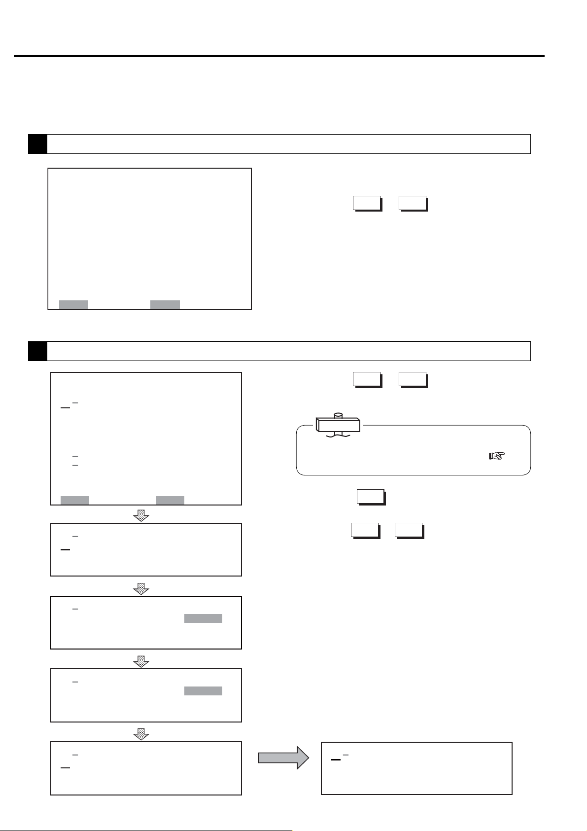
3.2.1 Connecting the Power
When the power is connected, the POWER light turns
ON and the following Hitachi logo display appears on
the LCD. After 5 seconds, monitoring display appears;
it shows operation type, discharge air pressure, total
operating hours, etc.
COMPRESSOR MONITOR
CONTROLLER
5 seconds
㻞㻜㻝㻞䠋㻜㻥䠋㻜㻝 㻝㻥䠖㻜㻞
㼀㼅㻼㻱䠖㼂㻿㻰㻭
㻰㻵㻿䠊㻼㻾㻱㻿㻿䠖 㻢㻣㼜㼟㼕
㻾㼁㻺 㻌㻴㻻㼁㻾䠖 㻝 㻞 㻜䡄
㻸㻻㻭㻰㻌 㻴㻻㼁㻾䠖 㻡㻠 䡄
㻸㻻㻭㻰 㼀 㻵 㻹㻱 㻿 䠖 㻝 㻞 㻟
㻸㻻㻭㻰 㻾㻭㼀㻱 䠖 㻝 㻝䠂
㻸㻻㻭㻰 㼀 㻵 㻹㻱 䠖 㻞 㻠 䡏
㼁㻺㻸㻻㻭㻰 㻌 㼀 㻵㻹㻱 䠖 㻝䡏
㻯㼁㻾㻾㻱㻺㼀 䠖 㻡 㻜䠝
㻲㻾㻱㻽㼁㻱㻺㻯㼅䠖 㻞 㻟 㻚 㻤䠤䡖
㻻㼁㼀㻼 㼁㼀 䠖 㻝 㻠 㻚 㻣 㻼
㻌㻌㻌㻌㻖
䠤
3.2.2 Start/Stop
When the START button is pressed, the START light
turns on and the compressor star ts operating.
When the compressor starts running, the asterisk on
the right side of running hours blinks and running time
starts to be counted.
To stop the operation, press the UNLOAD STOP
button. Operation stops after 5-minute drying of air end
and air piping.
To stop the compressor immediately without
unloading, press the STOP button.
Note) If the STOP button is pressed during unloading,
the compressor stops immediately.
IMPORTANT
(1) The air compressor does not start for 10 second after
power on to secure the safety.
For
15 seconds after power-on, the AUTO START light will
blink up to 10 seconds for operation preparation and
then the compressor starts running.
(2) Make sure that the door is closed before starting the
air compressor.
(3) Buttons, such as START/STOP/RESET function shall
be pressed for more than 0.3 seconds.
, if the START button is pressed within 10 to
3.2.3 Emergency Stop
※ The asterisk blinks when the clock and total
running hours are active.
If phase is reversed, “Connection Error: Reverse
Phase” will be displayed on the LCD monitor as a
setting/connection check message. In this case,
exchange 2 out of the 3 main power cables. If the air
compressor has control transformer in the control
panel, Open Phase is indicated as Reverse Phase. So
check the power cable connection of T Phase.
In case of open phase, “Connection Error: Open
Phase” will be displayed on the LCD monitor. In this
case, check the power cables.
Pressing EMERGENCY STOP button, the DSP
compressor immediately stops.
This switch should only be pressed in emergency.
The compressor can not be restarted until the switch is
manually reset.
Turn the switch knob clockwise and press the RESET
button to reset.
14
3. OPERATING PROCEDURE [How to Use the Liquid Crystal Display (LCD)]
3.3 How to Use the Liquid Crystal Display (LCD)
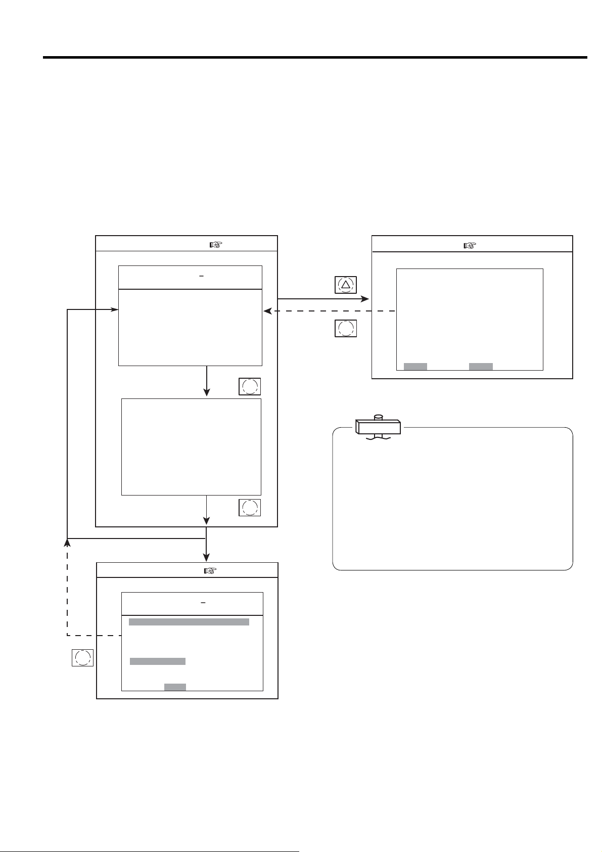
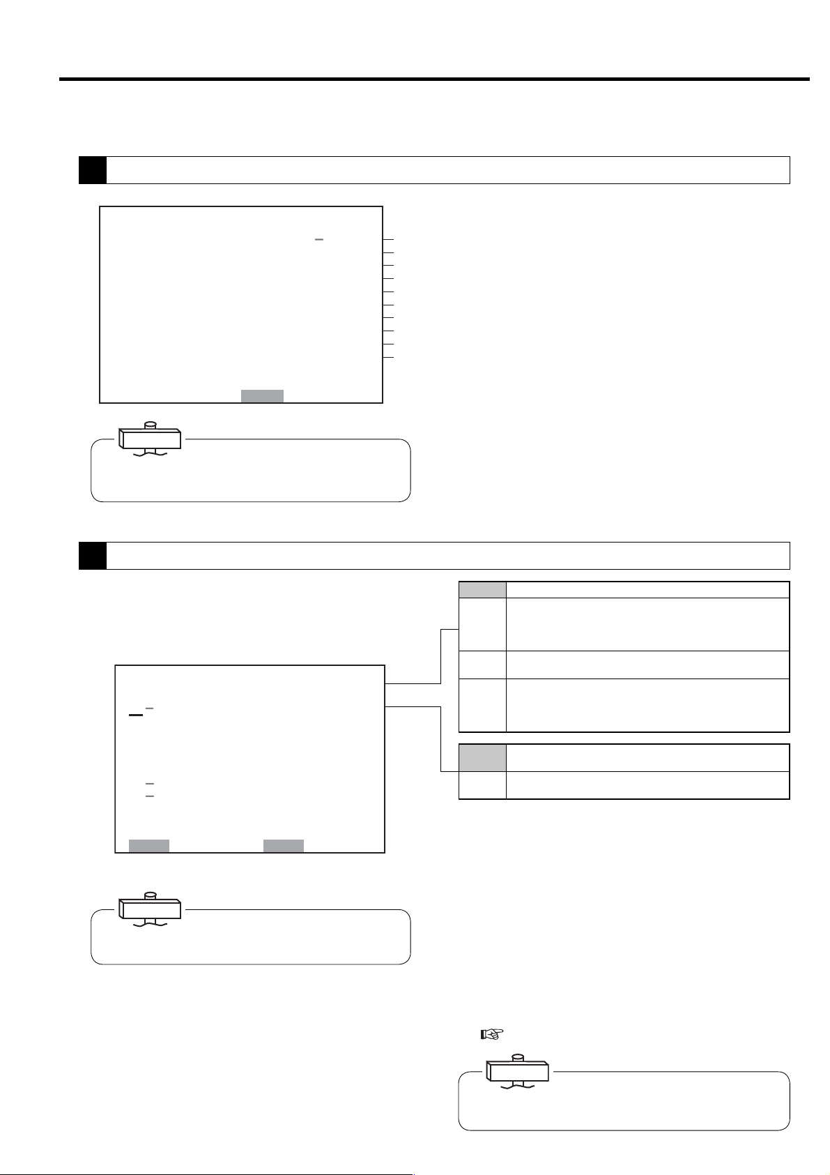
3.3.1 How to Move between the Various Displays
■Monitoring Displays
There are three monitoring displays as shown
below. This monitoring display is the top screen.
The monitoring display switches every time the
MONITOR button is pressed.
■Monitoring Display ( 3.3.2)
Monitor display 1
㻞㻜㻝㻞䠋㻜㻥䠋㻜㻝 㻝㻥䠖㻜㻞
㼀㼅㻼㻱䠖㼂㻿㻰㻭
㻰㻵㻿䠊㻼㻾㻱㻿㻿䠖 㻢㻣㼜㼟 㼕
㻾㼁㻺 㻌㻴㻻㼁㻾䠖 㻝㻞 㻜 䡄
㻸㻻㻭㻰 㻴㻻㼁㻾䠖 㻡 㻠䡄
㻸㻻㻭㻰 㼀 㻵 㻹㻱 㻿䠖 㻝 㻞 㻟
㻸㻻㻭㻰 㻾㻭㼀㻱 䠖 㻝 㻝䠂
㻸㻻㻭㻰 㼀 㻵 㻹㻱 䠖 㻞 㻠 䡏
㼁㻺㻸㻻㻭㻰 㼀 㻵 㻹㻱 䠖 㻝䡏
㻯㼁㻾㻾㻱㻺㼀 䠖 㻡 㻜䠝
MONITOR
㻲㻾㻱㻽㼁㻱㻺㻯㼅䠖 㻞 㻟 㻚 㻤䠤䡖
㻻㼁㼀㻼 㼁㼀 䠖 㻝 㻠 㻚 㻣
Monitor display 2
㻞㻜㻝㻞䠋㻜㻥䠋㻜㻝 㻝㻥䠖㻜㻞
㻼㻾㻱㻿㻿㼁㻾㻱
㻵㻺㼀㻿㼀㻳䠊㻼䠖 䚷䚷㻞㻥㼜㼟 㼕
㻻㻵㻸㻌㻼㻾㻱㻿䠖 㻌㻌 㻝㻡㼜㼟 㼕
㻯㻸㼀䠊㻼㻾㻱㻿䠖 㻖䠊㻖㻖 㼜 㼟 㼕
㼀㻱㻹㻼㻱㻾㻭㼀㼁㻾㻱
㻰㻵㻿䠊㼀㻱㻹㻼㻝䠖 㻟㻞㻜䉣
㻰㻵㻿䠊㼀㻱㻹㻼㻞䠖 㻟㻝㻟㻤䉣
㻻㻵㻸㻌㼀㻱㻹㻼䠖 㻟㻣䉣
㻯㻸㼀䠊㼀㻱㻹㻼䠖 㻖㻖㻖䉣
㻞㻺㻰 㻌 㻿㼁㻯㼀䠊㼀䠊䠖 㻜㻤 䉣
㻹㻭 㻵 㻺㼀 㻱㻺 㻭㻺㻯㻱
㻴㻾䠊㼀㻻㻌㻹㻭㻵㻺㼀䠖 㻜㻜㻜㻜䡄
㻺㻱㼄㼀㻌 㻹㻭 㻵㻺㼀䠖 㻖㻖㻖㻖
■Message Display ( 3.3.3)
Monitor display 3
㻞㻜㻝㻞䠋㻜㻥䠋㻜㻝 㻝㻥䠖㻜㻞 㻖
㼀㼅㻼㻱䠖㼂㻿㻰㻭
㻰㻵㻿䠊㻼㻾㻱㻿㻿䠖 㻢㻣
䠘㻿 㻴 㼁 㼀 㻰 㻻 㼃 㻺䠚
㻯㻻㻻㻸 㻭㻺㼀 䠖
㻻㻵㻸䠖
㻞䠪㻰㻌 㻿㼁㻯㼀䠊㼀㻱㻹㻼
㻴㻵㻳㻴 㻌㻰㻵㻿䠊㼀㻱㻹㻼䠖
㻯㻻㻺㼀 㻭㻯㼀 㻻㻾 㻌㻱㻾 㻾䠖
㻻㼂㻱㻾 㻸㻻㻭㻰 䠖
㻸㻻㼃㻌㼃䠊 㻵㻺 㼀㻿㼀㻳 㻌 㻼䠊
㻰 㻾 㼅 㻱 㻾 㻌㻌㻌㻌 㼃 䠋 㻻 㻌 㻿 㻱 㻼 䠊
㻱㻸㻱㻹㻱㻺㼀
㻼㼞㼑㼟㼟㻾㻱㻿㻌 㼍㼒 㼠㼑㼞 㻌㻯㻴㻷䠊
㼀㼁
MONITOR
MONITOR
㻌
㻌
䡇䠳
㻝
㼜㼟㼕
■ Menu Displays
Follow the bottom line message on the display.
■ Menu Screen ( 3.3.5)
Function Menu Display
MENU
MONITOR
㼇㻲㼁㻺㻯㼀㻵㻻㻺 㻹㻱㻺㼁㼉
㻝䠊㻮㻭㻿 㻵 㻯 㻿㻱㼀㼁㻼
㻞䠊㻹㼁㻸㼀 㻵 㻙 㼁㻺㻵 㼀
㻟䠊㻯㻭㻼㻭㻯㻵 㼀㼅 㻯㻻㻺㼀㻾㻻㻸
㻠䠊㻿㻯㻴㻱㻰㼁㻸㻱
㻡䠊㻻㻼㻱㻾㻭㼀 㻵㻻㻺 㻰㻭㼀㻭
㻢䠊㻸㻻㻭㻰 㻰㻭㼀㻭
㻣䠊㻭㻸㻭㻾㻹 㻴 㻵 㻿㼀㻻㻾㼅
㻤䠊㻿㻴㼁㼀㻰㻻㼃㻺 㻴 㻵 㻿㼀㻻㻾㼅
㻿㻱㼀䠖㻻㻼㻱㻺 㻹㻻㻺䠖㻮㻭㻯㻷
IMPORTANT
About the LCD Backlight
(1) In the event that no button has been used for 10
minutes, the LCD backlight automatically turns OFF for
protection to the display panel. It comes ON again if
any button is pressed, other than the START and STOP
buttons.
(2) If an event happens while the LCD backlight is off, the
backlight automatically turns ON and stays ON as long
as the event exists. Remote and instant stop mode
can't be set by the LCD monitor. Set after referring to
“3.4 How to Use the Digital Monitor.”
■ Message Display
Automatic restart/stop messages after shutdown or
warning occurrence and inspection/maintenance
messages is preferentially displayed in the Monitor
Display 3.
By pressing the MONITOR button here, the display
can be switched but is back to the Monitor Display 3
after approximately 10 seconds.
15
3. OPERATING PROCEDURE [How to Use the Liquid Crystal Display (LCD)]
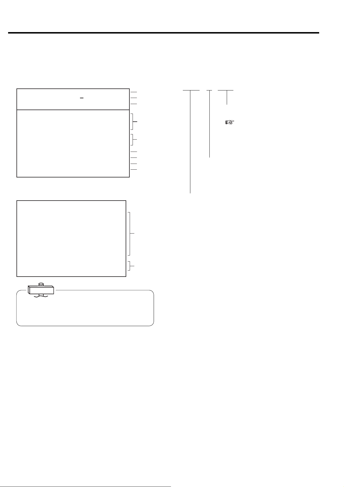
3.3.2 Monitoring Displays
■ Monitor Displays during Normal Operation
Monitor Display 1
㻞㻜㻝㻞䠋㻜㻥䠋㻜㻝 㻝㻥䠖㻜㻞
㼀㼅㻼㻱䠖㼂㻿㻰㻭
㻰㻵㻿䠊㻼㻾㻱㻿㻿䠖 㻢㻣㼜㼟㼕
㻾㼁㻺 㻌㻴㻻㼁㻾䠖 㻝㻞㻜䡄
㻸㻻㻭㻰㻌 㻴㻻㼁㻾䠖 㻡 㻠䡄
㻸㻻㻭㻰 㼀㻵㻹㻱㻿䠖 㻝㻞㻟
㻸㻻㻭㻰 㻾㻭㼀㻱 䠖 㻝 㻝䠂
㻸㻻㻭㻰 㼀 㻵 㻹㻱 䠖 㻞 㻠 䡏
㼁㻺㻸㻻㻭㻰 㻌 㼀 㻵 㻹㻱 䠖 㻝䡏
㻯㼁㻾㻾㻱㻺㼀 䠖 㻡 㻜䠝
㻲㻾㻱㻽㼁㻱㻺㻯㼅䠖 㻞 㻟 㻚 㻤䠤䡖
㻻㼁㼀㻼㼁㼀 䠖 㻝 㻠 㻚 㻣䡇
㻹㻭㻿㼀㻱 㻾
Monitor Display 2
㻞㻜㻝㻞䠋㻜㻥䠋㻜㻝 㻝㻥䠖㻜㻞
㻼㻾㻱㻿㻿㼁㻾㻱
㻵㻺㼀㻿㼀㻳䠊㻼䠖 㻌㻌 㻞㻥㼜㼟㼕
㻻㻵㻸㻌㻼㻾㻱㻿䠖 㻌㻌 㻝㻡㼜㼟 㼕
㻯㻸㼀䠊㻼㻾㻱㻿䠖 㻖䠊㻖 㻖㼜 㼟 㼕
㼀㻱㻹㻼㻱㻾㻭㼀㼁㻾㻱
㻰㻵㻿䠊㼀㻱㻹㻼㻝䠖 㻟㻞㻜䉣
㻰㻵㻿䠊㼀㻱㻹㻼㻞䠖 㻟㻝㻟㻤䉣
㻻㻵㻸㻌㼀㻱㻹㻼䠖 㻟㻣䉣
㻯㻸㼀䠊㼀㻱㻹㻼䠖 㻖㻖 㻖䉣
㻞㻺㻰㻌㻿㼁㻯㼀䠊㼀䠊䠖 㻜㻤䉣
㻹㻭 㻵 㻺㼀㻱 㻺㻭 㻺㻯㻱
㻴㻾䠊㼀㻻㻌㻹㻭㻵 㻺㼀䠖 㻜㻜㻜㻜䡄
㻺㻱㼄㼀㻌 㻹㻭 㻵 㻺㼀䠖 㻖 㻖 㻖 㻖
㻝
(1)
㻖
(2)
(3)
VSDA * SAVE
Indicates ECOMODE is activated for
㻖
(4)
(5)
(6)
㼃
(7)
(8)
(9)
Displayed when stop is limited for AUTO
operation (Standard: no symbol)
fixed speed type.
3.4.8)
(
INTE : Indicates fixed speed type used the standard, 2-step
䠆
control system.
AUTO : Indicates fixed speed type used the automatic motor
stop/restart capacity control system.
(10)
VSDB : Indicates Vtype without the AUTO capacity control.
VSDA : Indicates Vtype with the AUTO capacity control
(standard setting for Vtype).
EXIT : Indicated the external capacity control is used.
(11)
MR : Indicates multi unit control system through the
communication is used
IMPORTANT
“CURRENT” reading is an approximate S-phase Amp
reading.
“OUTPUT” reading is an approximate calculated power
reading.
(1) Indicates current time. An asterisk blinks.
(2) Indicates the control state.
(3) Indicates a discharge pressure (DIS.PRESS)
(4) Indicates total running hours (RUN HOUR), total
loaded hours (LOAD HOUR), and total number of
loads (LOAD TIMES).
Blinking asterisk means counting the running
hours.
(5) Indicates a percentage of load to unload of the DSP
air compressor (LOAD RATE).
For Vtype, the rate is calculated based on only
frequency. Indicates “***”, if PQ wide mode is
selected.
(6) Indicates the amperage current of the package
input (CURRENT).
(7) Indicates the operating frequency of the main motor
(FREQUENCY).
(8) Indicates “***” for this air compressor.
(9) Indicates (MASTER), when the air compressor is
master in lead-lag operation.
(10) Indicates each pressure and temperature. “***”
indicates not in use.
(11) Indicates the number of hours until the next
maintenance service (HR. TO MAINT), and the
next maintenance type (NEXT MAINT).
16
3. OPERATING PROCEDURE [How to Use the Liquid Crystal Display (LCD)]
3.3.3 Message Displays
■ Shutdown Messages
① When the shutdown occurs for the compressor, the SHUTDOWN light and shutdown contents on the LCD
monitor (contents are displays on the left side and details are displayed on the right side) blink and the
compressor stops running. There are 2 types of screens for shutdown: SHUTDOWN and FAILURE.
㻞㻜㻝㻞䠋㻜㻥䠋㻜㻝 㻝㻥䠖㻝㻥 㻖
㼀㼅㻼㻱䠖㼂㻿㻰㻭
㻰㻵㻿䠊㻼㻾㻱㻿㻿䠖 㻌㻌 㻢㻣㼜㼟㼕
䠘㻿 㻴 㼁 㼀 㻰 㻻 㼃 㻺䠚
㻯㻻㻻㻸 㻭㻺 㼀 䠖
㻻㻵㻸䠖
㻞䠪㻰 㻌 㻿㼁㻯㼀䠊㼀㻱㻹㻼
㻴㻵㻳㻴 㻌㻰㻵㻿䠊㼀㻱㻹㻼䠖
㻯㻻㻺㼀 㻭㻯 㼀㻻㻾 㻌㻱㻾㻾 䠖
㻻㼂㻱 㻾㻸 㻻㻭㻰 䠖
㻸㻻㼃㻌㼃䠊 㻵 㻺㼀㻿㼀㻳 㻌 㻼䠊
㻰 㻾 㼅 㻱 㻾 㻌㻌㻌㻌 㼃 䠋 㻻 㻌 㻿 㻱 㻼 䠊
㻱㻸㻱㻹㻱㻺㼀
㻼㼞㼑㼟㼟㻾㻱㻿㻌 㼍 㼒 㼠㼑 㼞 㻌㻯㻴㻷䠊
㼀㼁
㻌
(Example)
When the air compressor stops running with blinking
SHUTDOWN and OVERLOAD, it indicates the thermal relay
trip by overload.
2012䠋 01䠋 01 19䠖 19 *
TYPE䠖 VSDA
DIS䠊 PRESS䠖 46ps i
䠘 FA I LURE䠚
SYSTEM ERR䠖
SYSTEM RETRY
PCB ERR䠖
PRESS䠊 SNSR ERR䠖
TEMP䠊 SNSR ERR䠖 1
D 䡅 sconnect power
snd contact
di st r 䡅 but o r
(Example)
When the air compressor stops running with blinking FAILURE
and TEMP.SNSR ERR, the temperature sensor 1 is
disconnected.
② Take the proper corrective action, and press the RESET button.
For further information,
Section 4.
■ Alarm Messages
① When the alarm occurs for the air compressor, the ALARM light and contents / details displayed on alarm screen
on the LCD monitor blink and operation continues. There are 2 types of alarm screens: ALARM and PROBLEM.
㻞㻜㻝㻞䠋㻜㻥䠋㻜㻝 㻝㻥䠖㻝㻥 㻖
㼀㼅㻼㻱䠖
㻰㻵㻿䠊㻼㻾㻱㻿㻿䠖 䚷䚷㻢㻣㼜㼟㼕
䠘㻭 㻸 㻭 㻾 㻹䠚
㻰㻵㻿䠊㼀㻱㻹㻼䠖䠄㻌 㻌 㻌 䠅㻖㻖㻖䉣
㻻㻵㻸㻌㼀㻱㻹㻼䠖 㻖㻖㻖䉣
㻸㻻㼃㻌 㻻䠊㻼䠊䠖 㻖 㻖 㼜 㼟 㼕
㻯㻸㼀䠊㼀㻱㻹㻼䠊䠖 㻖 㻖 㻖䉣
㻸㻻㼃㻌 㻯㻸 㼀䠊㻼䠖 㻖 㻖 㼜 㼟 㼕
㻞䠪㻰㻙㻿䠊㼀㻱㻹㻼 㻌 㻲 㻵 㻺 㻙㼀
㻸㻻㼃㻌㼃䠊 㻸㻻㼃㻌 㻻 㻵 㻸
㻰㻾㼅㻱㻾 㻭㻵 㻾 㻌㻲㻵 㻸㼀㻱㻾
㻸䠊㻯㻻㼁㻺㼀㻌 㻻㼂㻱㻾 㻌㼃䠋㻻㻌 㻿䠊
㻼㼞㼑㼟䡏㻾㻱㻿 㼍㼒 㼠㼑 㼞 㻌㻯㻴㻷䠊
㻿㻰㻭㻌 㻌㻌 㻌㻌㻌
㼂
(Example)
When the ALARM and AIR FILTER blink, it indicates air
intake filter clogs.
㻞㻜㻝㻞䠋㻜㻥䠋㻜㻝 㻝㻥䠖㻝㻥 㻖
㼀㼅㻼㻱䠖 㼂㻿㻰㻭㻌
㻰㻵㻿䠊㻼㻾㻱㻿㻿䠖 䚷䚷㻢㻣㼜㼟 㼕
䠘㻼 㻾 㻻 㻮 㻸 㻱 㻹䠚
㻯㻻㻺㻺 㻱㻯 㼀 㻵 㻻㻺 㻌 㻱 㻾㻾 䠖㻌 㻌 㻌
㻾㼑㼏㼛㼚㼚㼑㼏㼠 㻌 㼜㼛㼣㼑 㼞䠊
㻹㼁㻸 㼀 䠥 㻙 㼁 㻿 㻱 㼀 㻱 㻾㻾
㻿㻯㻴㻱㻰㼁㻸㻱 㻌 㻿㻱㼀 㻌 㻱㻾㻾
㻯㻻㻹䠊㻱㻾㻾㻌㻿㼀㻻㻼䠖㻌㻌㻌㻌㻌
㻯㻻㻹䠊㻱㻾㻾㻌㻭㻸㻹䠖 㻌㻌㻌㻌㻌
㻮㻭㼀㼀 㻱㻾㼅 㻌㻻㼁㼀
㻼㼞㼑㼟㼟㻾㻱㻿 㼍㼒 㼠㼑 㼞 㻯 㻴㻷䠊
㻌㻌 㻌㻌㻌
(Example)
When the PROBLEM and BATTERY OUT blink, it indicates
the battery replacement period.
② Take the proper corrective action, and press the RESET button.
For further information,
Section 4.
NOTE) Malfunction detection of water failure (LOW W) is available for only water cooled single stage compressor.
Malfunction detection of dryer (DRYER) is available for only built-in dr yer models. Malfunction detection of
oil water separator (W/O SEP) is not available.
17

3. OPERATING PROCEDURE [How to Use the Liquid Crystal Display (LCD)]
■ Messages of Automatic Stop Display
When the air compressor stops automatically, the AUTO START light glows or blinks and RESTART display
appears. After the air compressor restarts, monitoring display appears again.
● SCHEDULED STOP: Schedule operation setting
<AUTO light glows>
This indicates that the air compressor has been
㻞㻜㻝㻞䠋㻜㻥䠋㻜㻝 㻝㻥䠖㻜㻞 㻖
㼀㼅㻼㻱䠖 㼂㻿㻰㻭㻌
㻰㻵㻿䠊㻼㻾㻱㻿㻿䠖 䚷䚷㻢㻣㼜㼟㼕
䠘㻾 㻱 㻿 㼀 㻭 㻾 㼀䠚
㻌㻌 㻌㻌㻌
automatically stopped by a pre-set time.
The air compressor starts automatically when the
pre-set restart time comes.
㻾㻱㻿㼀㻭㻾㼀 㻭㼀 䠖 䠆䠆䠖䠆䠆
㻾㻱㻿㼀㻭㻾㼀 㼃㻭 㻵 㼀 䠖 㻌 㻞 㻣䡏
㻺㻻㼃䠈㻿㼀 㻻㻼㻼 㻱 㻰 䠞䠵䠖
㻿㻯㻴㻱㻰㼁㻸㻱 㻿 㼀㻻㻼
㻭㼁㼀㻻㻹㻭㼀 㻵 㻯 㻿 㼀㻻㻼
㻰㻾㼅㻱㻾 㻼㻾 㻱㻿㼀㻭㻾 㼀㻱㻰
㻰㼁㻭㻸䠋㻮㻭㻯㻷㼁㻼
㻵㻼㻵 㻌㻾㻱㻿㼀㻭㻾㼀
㻯㼀㻸㻾䠊㻾㻱㼀㻾㼅
● LEAD/LAG OPERATION STOP (option)
<AUTO light glows>
This indicates that the air compressor is waiting for
starting as a slave unit in a two-unit-alternate
operation or a backup operation.
● DRYER PRESTARTED (Built-in dryer model)
<AUTO light blinks>
This indicates that the dryer has started and air
compressor is waiting for the start. The RESTART
WAIT field shows an expected waiting period until
the air compressor can start in seconds.
● AUTO OPERATION
<AUTO light glows>
This indicates that the air compressor in AUTO
operation has stopped due to the low air demand and
is waiting for restarting when demand is needed.
The RESTART WAIT field shows an expected
waiting period until the air compressor can restart in
seconds.
18
● INSTANT STOP / RETRY (Retry is for only Vtype)
<AUTO light blinks>
For both fixed speed and Vtype, this indicates that
the air compressor has stopped due to an
instantaneous power interruption (IPI). The
RESTART WAIT field shows an expected waiting
period until the air compressor can restart in
seconds.
For Vtype, this indicates that the air compressor has
stopped due to the variable speed drive failure and is
waiting for restart as well. The RESTART WAIT
field shows an expected waiting period until the air
compressor can restart in second.
3. OPERATING PROCEDURE [How to Use the Liquid Crystal Display (LCD)]
■ Maintenance Notice Messages
① Periodical maintenance
A maintenance date is determined by the amount of total operating hours or an elapsed calendar period, whichever
comes first. When the maintenance date or time arrives, the maintenance notice message appears on the display
under the heading of MESSAGE.
This function is only for the notice and is not output externally.
The consumable parts for the suction throttle valve shall be replaced this maintenance notice or L COUNT OVER
appears, whichever comes first.
㻞㻜㻝㻞䠋㻜㻥䠋㻜㻝 㻝㻥䠖㻜㻞 㻖
㼀㼅㻼㻱䠖 㼂㻿㻰㻭㻌
㻰㻵㻿䠊㻼㻾㻱㻿㻿䠖 㻌㻌 㻢㻣㼜㼟 㼕
䠘㻹㻱㻿㻿㻭㻳㻱䠚
㻹㻭 㻵 㻺 㼀䠊 䠖㻝 㼅 㻱 㻭㻾㻌 㻌
㻹㻭 㻵 㻺 㼀䠊䠯䠟䠤䠡䠠䠱㻸䠡 䠖 㻭
㻼㼞㼑㼟㼟㻿㻱㼀㻌㼍 㼒 㼠 㼑㼞 㻌㻯㻴㻷䠊
㻹㻭 㻵 㻺 㼀䠊㻯㻻㻹㻼 㻸 㻱 㼀 㻱㻰
㻿㼃 㻵 㼀㻯㻴㻱 㻰 㻌 㼀㻻 㻌 㻸㻻㻯㻭㻸
㻵㻺㻌㻻㼂㻱㻾䠮㻵㻰㻱 㻹㻻㻰㻱
㻵㻺㻌㼁㻺㻸㻻㻭㻰㻌㻿㼀㻻㻼
㻿㼃 㻵 㼀㻯㻴㻱 㻰 㻌 㼁 㻌 㻹㻻㻰㻱
㻌㻌 㻌㻌㻌
(1)
(2)
(3)
0.5 year, 1.5 years,
2.5 years, 3.5 years,
4.5 years, 5.5 years
1 year, 5 years Yearly + half-yearly
2 years, 4 years 2-yearly + yearly + half-yearly
3 years 3-yearly + yearly + half-yearly
6 years, overhaul 6-yearly + 3-yearly + 2-yearly + yearly + half-yearly
A
Standard Maintenance Schedule (A) (for yearly 8,000-or-less operating hours)
B
Standard Maintenance Schedule (B) (for yearly 4,000-or-less operating hours)
Half-yearly
CAUTION
If a message of maintenance notice is displayed, carefully read it and service the air compressor as
instructed by this manual. After servicing the air compressor, press the SET button and hold it down for
more than seven (7) seconds; the MAINT. COMPLETED message appears. After one (1) minute, the
monitor display appears.
Note:
1. MAINTenance can be reset, if the servicing is done earlier than expected and if the remaining operating time to next maintenance is
less than 2,000h in the case of A, 1,000h in the case of B.
2. On the contrary, if the servicing is done after the maintenance notice has appeared, the remaining operating hours to the next
maintenance has been zero until the maintenance is done. After maintenance and resetting the counter, new counting time starts
just after the maintenance notice message has appeared on the display.
② Other Message Displays
(1) SWITCH TO LOCAL
If set to local by remote operation following
shutdown restoration, the air compressor will
automatically return to local operation in case of
a shutdown, and the message will be displayed
for 1 minute. (
3.4)
(2) IN OVERRIDE MODE.
Indicates that the compressor is in override
mode.
(3) IN UNLOAD STOP
Blinks when the UNLOAD STOP button is used.
The air compressor unloads for 5 minutes and
then stop.
19
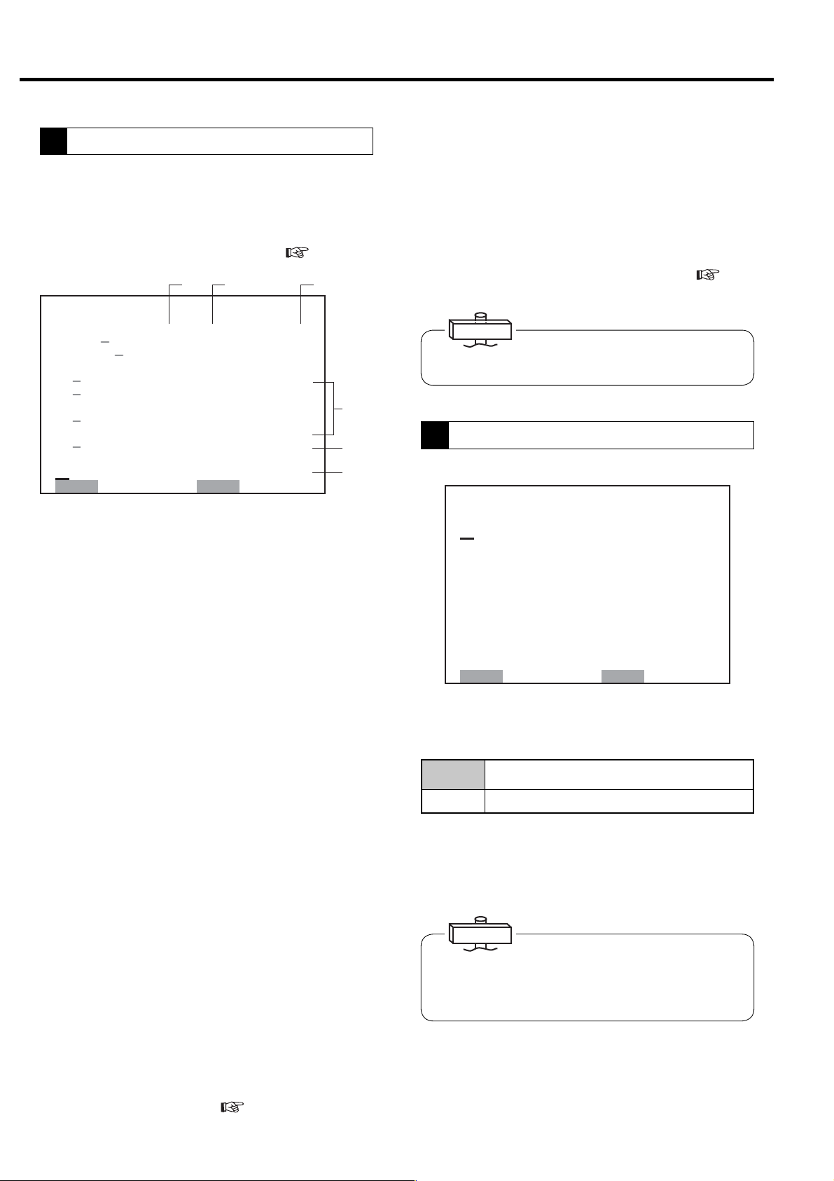
3. OPERATING PROCEDURE [How to Use the Liquid Crystal Display (LCD)]
3.3.4 How to Move within a Menu Display and to Change a Setting
The method and procedure for altering settings is displayed using the following as an example.
How to MOVE within a [FUNCTION MENU] Display
1
[FUNCTION MENU]
1 䠊 BAS I C SE T UP
2 䠊 MUL T I - UN I T
3 䠊 CAPAC I T Y CONTROL
4 䠊 SCHEDULE
5 䠊 OPE RA T I ON DAT A
6 䠊 LOAD DATA
7 䠊 ALARM HI STORY
8 䠊 SHUTDOWN HI STORY
or 2 is appeared
② Press the
desired item number.
③ Press the SET button to open the related setting
display.
The following explanation uses [MULTI-U SETTING
display] as an example.
① Press the MENU button when the monitor display 1
SET䠖 OPE N MON䠖 BACK
How to Select or Change a Setting within a Setting Display
2
㼇㻹㼁㻸㼀㻵㻙㼁㻌㻿㻱㼀㼀㻵㻺㻳㼉
① Press the
desired item number.
㻝
㻹㻻㻰 㻱 䠖 㻳㻸
㻞䠊㻰㼁㻭㻸 㻌 㼀 㻵 㻹㻱䠖 㻌 㻤䠊
㻟䠊㻹㻱㼀㻴㻻㻰䠖 㻭㻼
㻠䠊㻿㼃㻵㼀㻯㻴㻻㼂㻱㻾䠖 㻜㻝㻡 㼟
㻡䠊㻮㻭㻯㻷㼁㻼䠖 㻣㻼
㻢䠊㼁㻺㻸㻻㻭㻰䠖 㻟㻼㻿㼕
㻭㻸㼀䠊㼀 㻵㻹㻱䠖㻌 㻠㻤 㻜㻹 㻵 㻺
㻣
㻯㻻㻺㼀 㻾㻻 㻸 㻹㻻㻰 㻱 䠖 㻮
㻤
㻌㻿㻺
㻻㼂㻾 㻾㻸
㻜㼔
㻿㼕
IMPORTANT
Item number with a dash “-“ cannot be selected on LCD
monitor. It can be selected from digital monitor. (
How to Use the Digital Monitor for the detail.)
△
△
or
or
▽
buttons to move to the
buttons to move to the
▽
3.4
㻿㻱㼀䠖㻿㼀㻻㻾㻱 㻌 㻹㻻㻺䠖㻮㻭㻯㻷
①
㻝 㻹㻻㻰 㻱 䠖
㻞䠊㻰㼁㻭㻸 㻌 㼀 㻵 㻹㻱䠖 㻌 㻤䠊㻜 㼔
㻟䠊㻹㻱㼀㻴㻻㻰䠖
㻠䠊㻿㼃 㻵 㼀㻯㻴㻻㼂㻱㻾䠖 㻜㻝㻡㼟
㻻㼂㻾 㻾㻸
㻳㻸㻿㻺
㻭㻼
②
㻝 㻹㻻㻰 㻱 䠖
㻞䠊㻰㼁㻭㻸 㻌 㼀 㻵 㻹㻱䠖 㻌 㻤䠊㻜 㼔
㻟䠊㻹㻱㼀㻴㻻㻰䠖
㻠䠊㻿㼃 㻵 㼀㻯㻴㻻㼂㻱㻾䠖 㻜㻝㻡㼟
㻻㼂㻾 㻾㻸
㻳㻸㻿㻺
㻭㻼
③
㻝 㻹㻻㻰 㻱 䠖
㻞䠊㻰㼁㻭㻸 㻌 㼀 㻵 㻹㻱䠖 㻌 㻡䠊㻜 㼔
㻟䠊㻹㻱㼀㻴㻻㻰䠖
㻠䠊㻿㼃 㻵 㼀㻯㻴㻻㼂㻱㻾䠖 㻜㻝㻡㼟
㻻㼂㻾 㻾㻸
㻳㻸㻿㻺
㻭㻼
④
㻹㻻㻰 㻱 䠖
㻝
㻞䠊㻰㼁㻭㻸 㻌 㼀 㻵 㻹㻱䠖 㻌 㻡䠊㻜 㼔
㻟䠊㻹㻱㼀㻴㻻㻰䠖
㻠䠊㻿㼃 㻵 㼀㻯㻴㻻㼂㻱㻾䠖 㻜㻝㻡㼟
㻻㼂㻾 㻾㻸
㻳㻸㻿㻺
㻭㻼
② Press the
button to move to the desired
▽
setting field.
③ Press the
△
or
buttons until the desired
▽
setting appears.
④ Press the SET button to return to the item number.
⑤ Press the SET button again to return to the item
number 1. This saves the changed setting.
Press the MONITOR button to return to the
[FUNCTION MENU] display. Press the MONITOR
button again to view the monitoring display.
㻝 㻹㻻㻰 㻱 䠖
⑤
㻞䠊㻰㼁㻭㻸 㻌 㼀 㻵 㻹㻱䠖 㻌 㻡䠊㻜 㼔
㻟䠊㻹㻱㼀㻴㻻㻰䠖
㻠䠊㻿㼃 㻵 㼀㻯㻴㻻㼂㻱㻾䠖 㻜㻝㻡㼟
㻻㼂㻾 㻾㻸
㻳㻸㻿㻺
㻭㻼
20
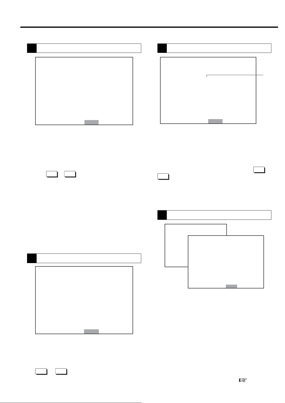
3. OPERATING PROCEDURE [How to Use the Liquid Crystal Display (LCD)]
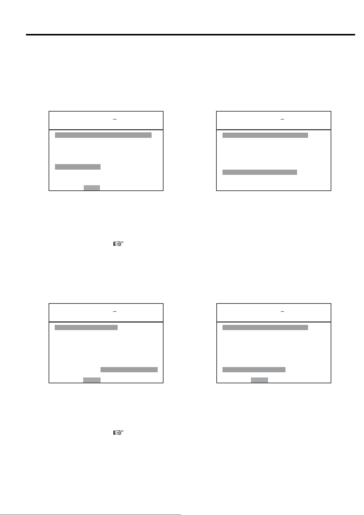
3.3.5 [FUNCTION MENU] - Setting Displays
Model Setting Confirmation
1
㼇㻮㻭㻿㻵㻯 㻿㻱㼀㼁㻼㼉
㼂㻱㻾䠊䠖 㻡䠊㻜
㻿㻱㻾 㻵 㻱㻿 㻺㻭㻹㻱䠖 㻰㻿㻼
㻯㻻㻻㻸 㻵 㻺㻳 㻹㻱㼀 㻴㻻㻰 䠖 㼃㼀㻾
㻺㻻䠊㻻㻲 㻿 㼀 㻭㻳 㻱 䠖 㻌 㻞
㻼㻙㻿㻼㻱㻯䠖 䚷㻝 㻜 㻜㼜 㼟 㼕
㻼䠊㻰㻭㼀㻭䠖 䚷䚷 㻢 㻤 㼜 㼟 㼕
䠟䠰 䠖 㻞 㻡 㻜䠝
㻯㻸㼀䠊㻰㻱㻸㻭㼅䠖 㻌 㻡 㼟
㻵㻼㻵䠖 㻵 㻵 㻵
㻭㻰㻾㻱 㻿㻿 㻺㻻䠊䠖 㻌 㻝
㻹㻻㻺 䠖 㻮 㻭㻯㻷
IMPORTANT
When contacting the local Hitachi distributor, inform
this information as a based setting status.
㻡䠊㻜
①
②
③
④
⑤
⑥
⑦
⑧
⑨
⑩
This display contains software version (VER.), air
compressor series (SERIES NAME), cooling method
(COOLING METHOD), number of air compression
stages (NO. OF STAGE), action against instantaneous
power interruption (IPI) and etc. “** ” means the
setting that is not required.
① Indicates board software version.
② Indicates compressor type.
③ Displays cooling type.
④ Displays the number of compressor stages.
⑤ Displays pressure specification.
⑥ Displays interstage pressure.
⑦ Indicates CT setting value.
⑧ Displays water failure detection conditions for water
cooled compressor.
⑨ Displays status of instantaneous power interr uption
(IPI) restart setting.
⑩
Displays compressor number. (Must be distinguished
by number is using communication function.)
Operation Mode Setting
2
Confirm the settings by lead/lag and multi unit
control (option). These options need wiring
modification. Item number with a dash “-“ cannot be
selected on LCD monitor.
㼇㻹㼁㻸㼀㻵㻙㼁㻌㻿㻱㼀㼀㻵㻺㻳㼉
㻝
㻹㻻㻰 㻱 䠖 㻳㻸
㻞䠊㻰㼁㻭㻸 㻌 㼀 㻵 㻹㻱䠖 㻌 㻤䠊
㻟䠊㻹㻱㼀㻴㻻㻰䠖 㻭㻼
㻠䠊㻿㼃㻵㼀㻯㻴㻻㼂㻱㻾䠖 㻜㻝㻡 㼟
㻡䠊㻮㻭㻯㻷㼁㻼䠖 㻌 㻌 㻌 㻣㼜
㻢䠊㼁㻺㻸㻻㻭㻰䠖 㻌 㻌 㻌 㻟㼜 㼟 㼕
㻭㻸㼀䠊㼀 㻵㻹㻱䠖㻌 㻠㻤 㻜㻹 㻵 㻺
㻣
㻯㻻㻺㼀 㻾㻻 㻸 㻹㻻㻰 㻱 䠖 㻮
㻤
㻿㻱㼀䠖㻿㼀㻻㻾㻱 㻌 㻹㻻㻺䠖㻮㻭㻯㻷
1- MODE:
If using the backup function, switch to the digital
monitor for setting.
Operation mode set on the digital monitor.
IMPORTANT
㻌㻿㻺
㻜㼔
㻻㼂㻾 㻾㻸
㼟㼕
2. DUAL TIME: Alternate operation hours of lead/
lag operation.(Setting range : 0.1 to 99.9 hours;
initial value: 8.0)
3. METHOD: Switching method (overlap or interval)
of lead/lag operation.
4. SWITCHOVER: Switching-over or overlapping
period of lead/lag operation. (Setting range : 5 to
300 seconds; initial value: 15)
SNGL Operates an air compressor independently
Operates by multi roller EX of exclusive use for NEXT
series using communication function.
STPR
By this setting RS485 communication port is effective.
The setting of air compressor number is required.
DUAL
BKUP
OVERLAP
INTERVAL
Operates two air compressors alternately according to
a time schedule. The AUTO light comes ON (glowing).
Operates two air compressors according to a preset
back up pressure. Starts the back up slave unit when
the pressure has dropped to the desired preset back up
pressure. The AUTO light comes ON (glowing)
Slave unit starts, master/slave units overlap in operation
for a preset period, and then master unit stops.
Master unit stops, a non-operating interval passes, and
then slave unit starts.
5. BACKUP: Pressure to start a backup unit in a
backup operation (cut-in (load) pressure – α)
6. UNLOAD: Pressure to unload both the units in a
backup operation (cut-out (unload) pressure – α)
7- ALT. TIME: Displays time remaining until switch for
dual / backup operation. Time is not counted down
when operating 2 units for backup operation. When
operation is stopped, remaining time is maintained.
8- CONTROL MODE: Control mode A or B for Vtype
(
3.3.2). “**” is indicated in fixed speed type.
IMPORTANT
The settings can be memorized while the air compressor
is stopped.
21
3. OPERATING PROCEDURE [How to Use the Liquid Crystal Display (LCD)]
Capacity control
3
This function sets the pressures and times for capacity
control. Two dif ferent combinations (P1 and P2) of
pressures can be used. Item number with dot “ . ” can
be select from LCD monitor. Item number with a dash “
- “ can be selected from digital monitor. (
3.4)
①② ③
㼇㻯㻻㻺㼀㻾㻻㻸 㻿㻱㼀㼀 㻵㻺㻳㼉
㻝䠊㼀㼅㻼㻼㻱䠖㼂㻭 㼎㼎㼎 㼏㼏㼏
㻞䠊䠬
㻟䠊䠬 㻵
㻠
㻡
㻢
㻣
㻤䠊㼀 㻵㻹㻱䠖㻝㻤䠖 㻜㻜 㻞㻞䠖 㻜㻜
㻿㻱㼀䠖㻿㼀㻻㻾㻱 㻌 㻹㻻㻺䠖㻮㻭㻯㻷
㻸㻻㻿㻿䠖 㻖㻖 㼜 㼟 㼕
㻯㻭䠖㻖㻖㻖 㻖㻖䠊㻖䡉㻟
䠄㻯㻻㻺㼀㻾㻻㻸䠋㻯㼁㼀㻙 㻵㻺 㻕
㻼㻝䠖 㻌 㻝 㻜㻜䠋㻌 㻌 㻤㻣㼜 㼟 㼕
㻼㻞䠖 㻌 㻝 㻜㻜䠋㻌 㻌 㻤㻣㼜 㼟 㼕
䠄㼀㻭㻾㻳㻱㼀㻌㻼㻝䠋㻼㻞 㻕
㼀㻭㻾㻳㻱㼀䠖
㻌㻌 㻥㻤䠋㻌㻌 㻥㻤㼜㼟 㼕
㼀㻵㻹㻱㻌㻸㻵㻹㻵㼀䠖 㻜㻟㻜㼟
䠄㻼㻞 㻱㻲㻲㻱㻯ࠥ㼀㻵㼂㻱㻕
④
⑤
⑥
1. Type: Indicates the setting data for capacity control
① Type of capacity control (Cannot be changed from
LCD monitor)
Fixed speed type
I: Indicates the standard, 2-step control.
IP: Indicates the motor stop/restart capacity control
to “I”.
Vtype
VA: Indicates motor stop/restart capacity control is
effective.
VB: Indicates motor stop/restart capacity control is
canceled.
② Pressure setting (Cannot be changed from LCD
monitor)
S-1: Indicates pressure setting 1
S-2: Indicates pressure setting 2
EXT: Indicates external pressure setting
S-A : Indicates pressure setting switches by set time
on ⑥.
③ Option condition and setting.
NUL: Indicates no option.
2. - 3. OPTION: Used for options.
4. - 6. Pressure Setting: ④ Indicates cut-in, cut-out
and target pressure setting 1 and 2 can be confirmed.
Target means target pressure for ECOMODE
7. TIME LIMIT (Fixed speed type only)
⑤ Indicates the time limit of load/unload one-cycle
time for ECOMODE. Load/unload one-cycle time
must be 30 seconds or more. (
3.4.8)
8. TIME: ⑥ Can set the time to use pressure setting 2.
When set the value properly, ② is indicated in “ S-A”. If
the start and stop time is set at same value, pressure
setting 2 is not in use and ② is indicated in S-1. And
pressure setting 1 and 2 can be changed by external
switch. Set the F018 on digital monitor “2”. (
3.4.2
and 3.4.7)
IMPORTANT
The settings can be memorized while the air compressor
is stopped.
Scheduled Operation
4
Allows a standard daily scheduling operation.
㼇㻿㻯㻴㻱㻰㼁㻸㻱㻌㻿㻱㼀㼀㻵㻺㻳㼉
㻝䠊㻹㻻㻰㻱 䠖 㻯㻴㻱㻰㼁㻸㻱
㻿㼀㻭㻾㼀 㻿㼀㻿㻻㻼
䠄㻝䠅㻜㻣䠖㻜㻜㻌 㼅 㻞㻜䠖㻜㻜㻌 㼅
䠄㻞䠅㻜㻜䠖㻜㻜㻌 㻺 㻜㻜䠖㻜㻜 㻌 㻺
䠄㻟䠅㻜㻜䠖㻜㻜㻌 㻺 㻜㻜䠖㻜㻜 㻌 㻺
䠄㻠䠅㻜㻜䠖㻜㻜㻌 㻺 㻜㻜䠖㻜㻜 㻌 㻺
䠄㻡䠅㻜㻜䠖㻜㻜㻌 㻺 㻜㻜䠖㻜㻜 㻌 㻺
㻞䠊㻾㻱㻯㻻㻾㻰 㻝䠖 㻝㻜䠖㻜㻜
㻟䠊㻾㻱㻯㻻㻾㻰 㻞䠖 㻝㻥䠖㻜㻜
㻿㻱㼀䠖㻿㼀㻻㻾㻱 㻌 㻹㻻㻺䠖㻮㻭㻯㻷
This illustration indicates a scheduling operation from 7:00 to
20:00. TIME field indicates a current time of 19:07.
㻝㻥䠖㻜㻣
1. MODE:
OFF Operates without a schedule.
Schedule Operates according to a daily 24- hour calendar.
(1) to (5) : Five Start/Stop Time Patterns
・ START : Star ting Time
・ STOP : Stopping Time
・ Y or N : Starts or Stops as scheduled
IMPORTANT
When the schedule is selected, the AUTO light comes ON
(glowing) if the time setting is valid and ON (blinking) if the
time setting is invalid. The settings can be memorized
while the air compressor is stopped.
2.-3. RECORD1, 2 : This function allows for the
capability to record data over a desired time in a day.
To view the recorded data, refer to “5. Operation data
display” on the next page.
22
3. OPERATING PROCEDURE [How to Use the Liquid Crystal Display (LCD)]
Operation Data Display
5
㼇㻻㻼㻱㻾㻭㼀 㻵㻻㻺 㻰㻭㼀㻭㼉
㻝䠊㻜㻤䠋㻜㻝 㻝 㻜 䠖 㻜 㻜
㻼䠖㻜㻠㻢䚸㻜㻝㻥䚸㻜㻝㻢䚸㻖㻖㻖
㻯䠖 㻜
㼀䠖 㻞㻡䚸 㻟㻟䚸㻖㻖䚸㻖㻖䚸㻖㻖
㻸䠖 㻡㻥䚸㻝㻤䠊㻤
㻞䠊㼍 㼍䠋㼎 㼎 㼏 㼏 䠖㼐㼐
㻼䠖㻖㻖㻖䚸㻖㻖㻖䚸㻖㻖㻖䚸㻖㻖㻖
㻯䠖㻖㻖㻖
㼀䠖㻖㻖㻖䚸㻖㻖㻖䚸㻖㻖䚸㻖㻖䚸㻖㻖
㻸䠖㻖㻖㻖䚸㻖㻖㻖㻖㻖
㻹㻻㻺 䠖 㻮 㻭㻯㻷
Data can be recorded for a maximum of twelve (12)
times. The 13th recorded data is automatically deleted
and the 1st recorded data is added. The most recent
data is arranged at the top of the display. If a change to
these settings is desired, the sampled data before the
settings change will be left as is and the new recorded
data will be applied after the change.
Press the
△
or
▽
button to move within the display.
1. and 2. : Indicates the MONTH / DAY HOUR: MINUTE.
P - Represents a pressure (psi) and indicates from left
to right: Discharge air pressure, Interstage
pressure, Oil pressure, ***
C - Represents an amperage current (A)
T - Represents a temperature (°F) and indicates from
left to right: 1st stage discharge air temperature,
2nd stage discharge air temperature, oil
temperature, ***, 2nd stage suction temperature.
L -Represents a load ratio percentage (%)
Unavailable fields are filled with asterisks.
Load Data Display
6
㼇㻸㻻㻭㻰 㻰㻭㼀㻭㼉
㻝䠊㻜㻤䠋㻜㻝
㻭㼂㻳䠊㻼㻾㻱㻿㻿 䠖 㻌 㻌 㻣 㻡 㼜 㼟 㼕
㻭㼂㻳䠊㻯㼁㻾㻾㻱 㻺㼀 䠖 㻜 㻠 㻜䠝
㻭㼂㻳䠊㻸㻻㻭㻰 㻾㻭㼀㻱䠖㻜㻢㻡䠂
㻭㼂㻳䠊㻼䠫䠳䠡䠮䠖 㻌 㻝 㻣 㻚 㻤 㼗㼃
㻞䠊㻜㻝䠋㻜㻝
㻭㼂㻳䠊㻼㻾㻱㻿㻿 䠖 㻌 㻌 㻣 㻡 㼜 㼟 㼕
㻭㼂㻳䠊㻯㼁㻾㻾㻱 㻺㼀 䠖 㻜 㻠 㻜䠝
㻭㼂㻳䠊㻸㻻㻭㻰 㻾㻭㼀㻱䠖㻜㻢㻡䠂
㻭㼂㻳䠊㻼䠫䠳䠡䠮䠖 㻌 㻞 㻟 㻚㻤 㼗㼃
㻹㻻㻺 䠖 㻮 㻭㻯㻷
㻡
This display shows the averaged load data per day. Data
can be recorded for a maximum of 6 days; the 7th day
of averaged load data is automatically deleted and the
1st or most recent averaged data is added. The most
recent data is arranged at the top of the display. Press
the
△
or
▽
button to move within the display.
Data is averaged from start to stop every day. If 24h
operation is done, data is averaged at AM 0:00.
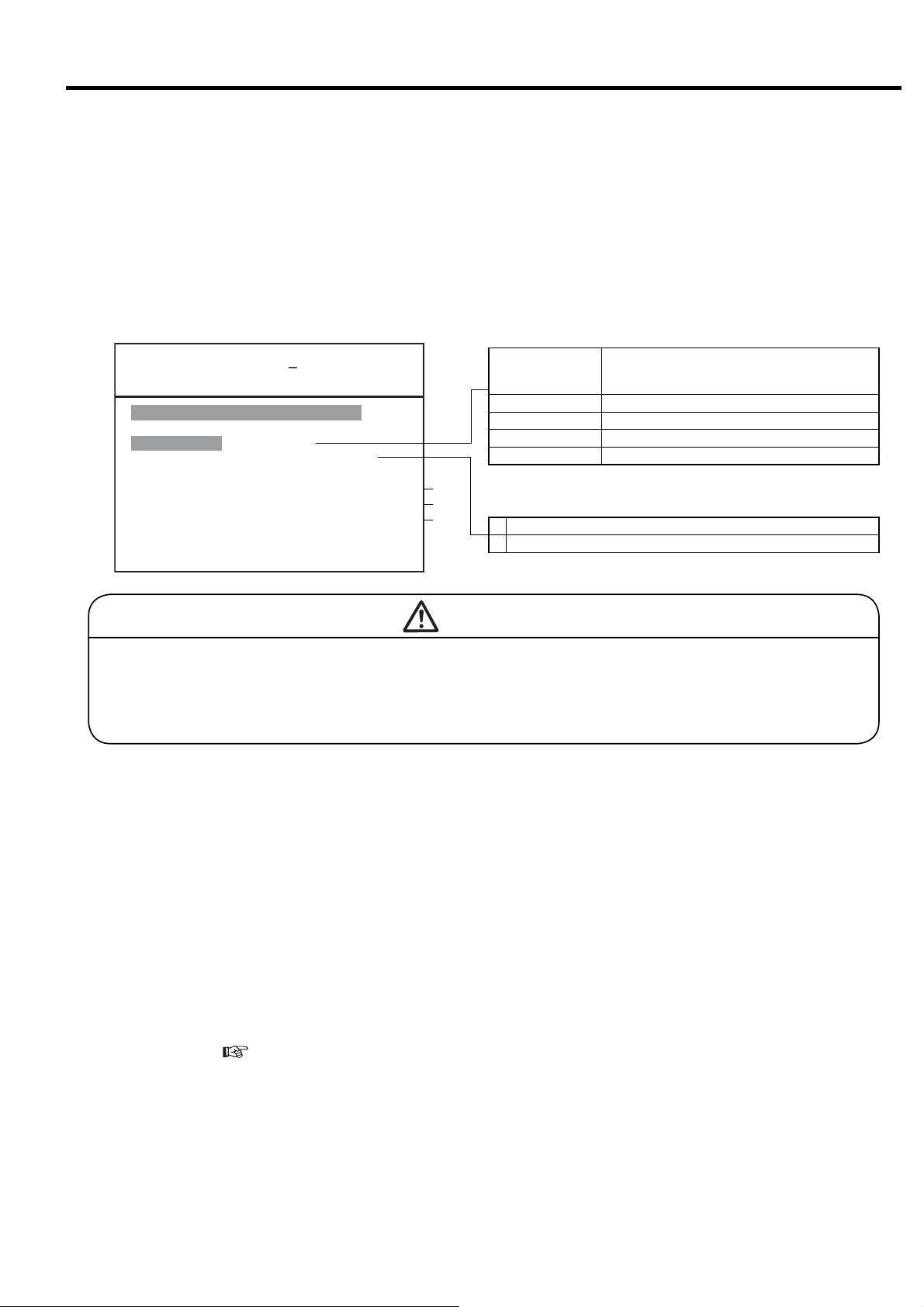
Alarm History
7
㼇㻭㻸㻭㻾㻹 㻴 㻵㻿㼀㻻㻾㼅 㼉
㻝䠊 㼍㼍㼍㼍㼍㼍㼍㼍㼍㼍㼍㼍㼍
㻯㻻㻰㻱䠖㻞㻝㻸 㻺㻻㻿䠊䠖㻌 㻝
㻜㻣䠋㻜㻤䠋㻜㻝 㻝㻥䠖 㻞㻢
㻞䠊 㻖㻖㻖㻖㻖㻖㻖㻖㻖㻖㻖㻖㻖
㻯㻻㻰㻱䠖㻖㻖㻖 㻺㻻㻿䠊䠖㻖㻖
㻖㻖䠋㻖㻖䠋㻖㻖 㻖㻖䠖 㻖㻖
㻟䠊 㻖㻖㻖㻖㻖㻖㻖㻖㻖㻖㻖㻖㻖
㻯㻻㻰㻱䠖㻖㻖㻖 㻺㻻㻿䠊䠖㻖㻖
㻖㻖䠋㻖㻖䠋㻖㻖 㻖㻖䠖 㻖㻖
㻹㻻㻺 䠖 㻮 㻭㻯 㻷
①
This display shows a maximum of 6 alarms and
displays the following information as such: type of
alarm, the number of times, and the date and time. If
the same alarm occurs in a short period of time, the
older data is deleted and the more recent data is stored,
and alarm NOS. is updated. The most recent data is
arranged at the top of the display. Press the
▽
button to move within the display.
△
or
① Indicates operating condition.
L: When loading, U: When unloading,
S: When Stopped
Shutdown History
8
㼇㻲㼁㻺㻯㼀㻵㻻㻺 㻹㻱㻺㼁㼉
㻝䠊㻮㻭㻿㻵 㻯㻌 㻿㻱㼀㼁㻼
㻞䠊㻹㼁㻸㼀 㻵 㻙㼁㻺 㻵 㼀
㻟䠊㻯㻭㻼㻭㻯㻵 㼀㼅 㻯㻻㻺㼀㻾㻻㻸
㻠䠊㻿㻯㻴㻱㻰㼁㻸㻱
㻡䠊㻻㻼㻱㻾㻭㼀 㻵㻻㻺 㻰㻭㼀㻭
㻢䠊㻸㻻㻭㻰 㻰㻭㼀㻭
㻣䠊㻭㻸㻭㻾㻹 㻴㻵 㻿㼀㻻㻾㼅
㻤䠊㻿㻴㼁㼀㻰㻻㼃㻺 㻴㻵 㻿㼀㻻㻾㼅
㻿㻱㼀䠖㻻㻼㻱㻺 㻹㻻㻺䠖㻮㻭㻯㻷
㼇㻰㻱㼀㻭㻵 㻸㻿㼉
㻝䠊 㼍㼍㼍㼍㼍㼍㼍㼍㼍㼍㼍㼍㼍
㻰㻵㻿䠊㻼㻾㻱㻿䠖 㻌㻌 㻠㻤㼜㼟㼕
㻵㻺㼀㻿㼀㻳䠊㻼䠖 㻖㻖㼜㼟㼕
㻻㻵㻸 㻼㻾㻱㻿䠖 㻖㻖㼜㼟㼕
㻯㻸㼀䠊㻼㻾㻱㻿䠖 㻖㻖 㼜 㼟 㼕
㻰㻵㻿䠊㼀㻱㻹㻼䠊㻝䠖 㻝㻤㻜䉣
㻰㻵 㻿䠊㼀㻱㻹㻼䠊㻞䠖 㻝㻤㻜䉣
㻻㻵㻸 㼀㻱㻹㻼䠖 㻖㻖㻖䉣
㻯㻸㼀䠊㼀㻱㻹㻼䠖 㻖㻖㻖䉣
㻞㻺㻰 㻿㼁㻯㼀䠊㼀䠖 㻖㻖 㻖䉣
㻯㼁㻾㻾㻱㻺㼀䠖 㻝㻜㻜㻭
㻹㻻㻺 䠖 㻮 㻭㻯 㻷
This display shows a maximum of 6 shutdowns and
displays the following information as such: type of
shutdown, the number of times the air compressor has
shutdown, and the date and time of the shutdown. The
shutdown history display also shows the operation data
(pressure, temperature, current) sampled at the time of
shutdown.
To view the operation data sampled when the shutdown
occurred; in the shutdown histor y display, move to the
item number of the targeted shutdown to view. Press
the SET button to open the [DETAILS] display.
● How to clear the all alarm and shutdown histories.
Set the F041 on digital monitor “1”. (
3.4.2).
23
3. OPERATING PROCEDURE [How to Use the Liquid Crystal Display (LCD)]
3.3.6. Other Settings
Initial Setting
The calendar and clock are set by Hitachi prior to
delivery. To reset the calendar and clock, contact
the local Hitachi distributor.
Brightness Adjusting
Adjust the LCD brightness as follows:
To brighten:
Hold down the SET button and press the
MONITOR button.
To darken:
Hold down the SET button and press the
FUNCTION button.
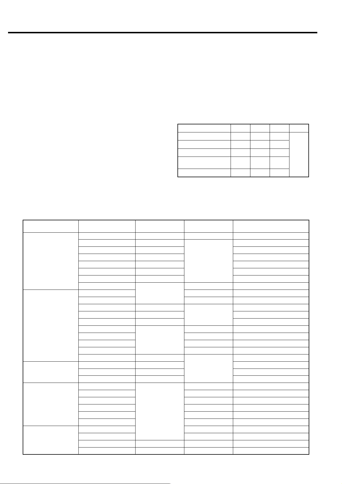
Digital Monitor Operation Classification
The following is a table of contents that can be set by
the LCD monitor and digital monitor (next section).
Function Item
MULTI-U SETTING
display
CONTROL SETTING
display
SCHEDULE SETTING
display
Other settings
Reset
MODE -
DUAL TIME
METHOD
SWITCHOVER
BACKUP
UNLOAD
ALT.TIME
CONTROL MODE
TYPE (left)
TYPE (center)
TYPE (right)
P-LOSS
PI-CA
P1
P2
TARGET - Prohibited to change
TIME LIMIT
TIME
MODE
START/STOP
RECORD 1, 2
Air compressor No.
IPI
Remote operation
Dryer operation
AUTO operation
ECOMODE
Shutdown/Alarm
Load count
Maintenance
Shutdwon/Alarm history
△
3-Language Display Switch
The language of the display can be switched to
Japanese, English or Chinese by the dip switch on
the back of the LCD monitor board. If the language
needs to be changed, consult with the local Hitachi
distributor.
Japanese OFF OFF OFF
English ON OFF OFF
Chinese OFF ON OFF
Setting for United
States
Test mode ON ON OFF
Power must be turned off before setting.
LCD monitor
operation
○
○
○
○
○
(automatic change)
-
○
○
○
-
○
○
○
○
-
○
-
Bit 1 2 3 4 - 8
ON OFF ON
Digital monitor
(F mode)
○ F000
-
○ (Factory set)
○ F019
○ F018
-
○ F022 -
○ F022 -
○ (Factory set)
-
○ F001
○ F002 -
○ F005 -
○ F008 -
○ F011 -
○
○
○
- Set button 7 sec. ON
○ F041
Dual, backup, etc
Differential pressure
Differential pressure
V type only
Example: I type (load/unload type)
Example: Setting 1
Option (not supported)
Option (not supported)
Option (not supported)
Setting 1, Setting 2
Setting 1, Setting 2
Energy saving mode decision time
Function switching
Operation data measurement
Display switch button operation
Reset button operation
Remote + display switch button
Remarks
Not
used
24
3. OPERATING PROCEDURE [How to Use the Digital Monitor]
3.4 How to Use the Digital Monitor
3.4.1 How to Display Operation Status, Shutdown History, and Status of Various Settings
All display contents of the digital monitor are linked with the LCD monitor. All of the following display contents can
be confirmed by the LCD monitor.
Use the following operations to display the contents of other operation/setting status on the LCD monitor and
readily confirm operation status and setting status by the digital monitor.
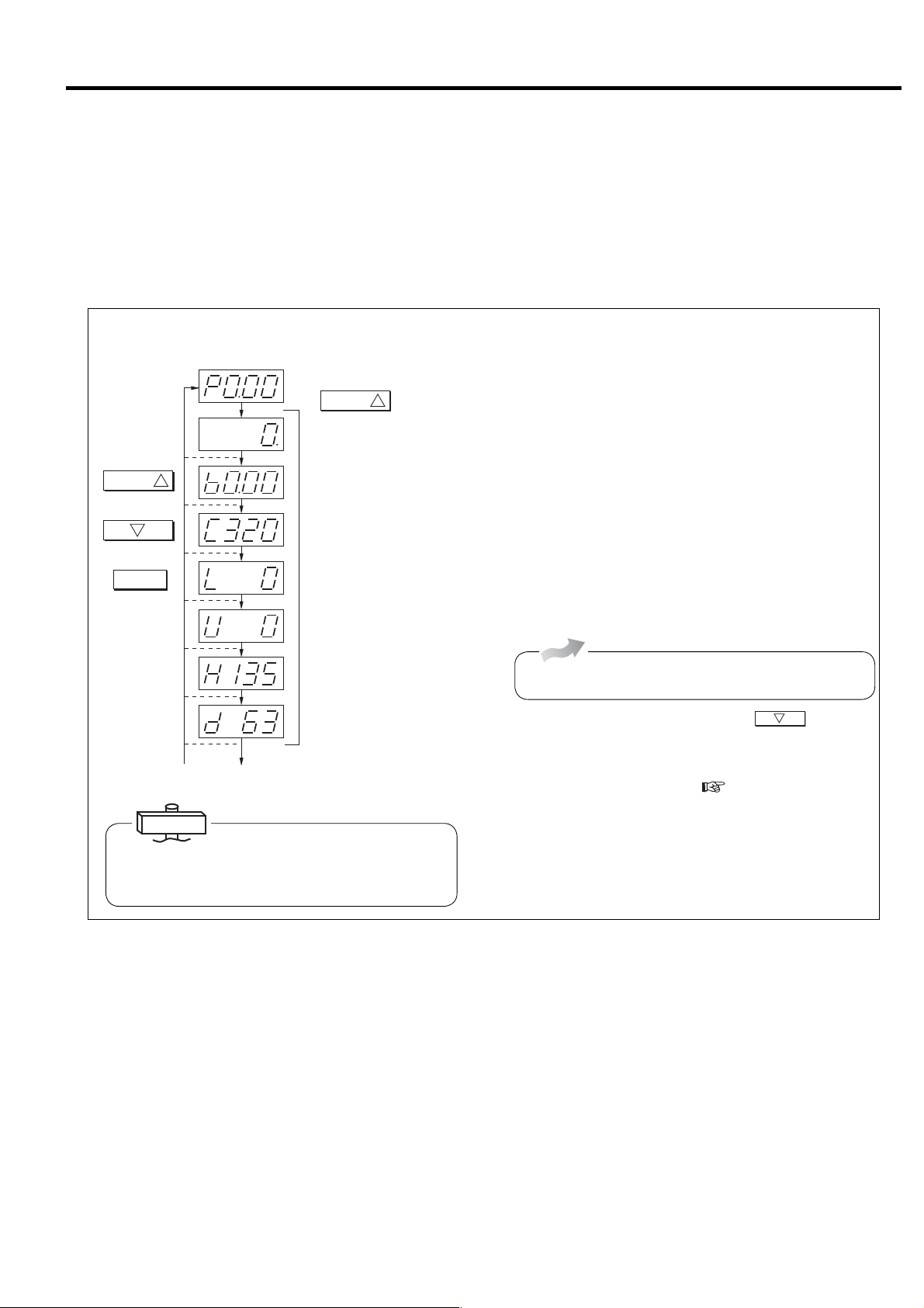
(1) How to Display the Operation Status
P: Discharge pressure (psi)
SELECT/WIDE
Blinks when operation time is added.
Total running hour (×10)
SEL ECT /WID E
Pres s once to go to
the next item.
Press once to go to
the previous item.
Return to discharge
pressure display
2
RESET
1
To shutdown history display
b: Interstage pressure (psi)
C: 1st-stage air end outlet temp (゜F)
(320゜F)
L: Vtype: Not in use
Fixed speed type: Load ratio (%)
U: Load count (×10,000 times)
H:
Vtype: Main motor operating frequency (Hz)
Fixed speed type: Not in use (display only)
d: Fan motor operating frequency (Hz)
Water-cooled type: Not in use (display only)
IMPORTANT
1. When other than P (Discharge pressure is
displayed), it automatically returns to P in 3 minutes.
2. Load ratio is a reference-calculated value.
1
Press
When the power is turned on, discharge pressure is displayed
on the screen of the digital monitor. Use the following
procedure to switch the digital monitor to other display.
① Press the SELECT/WIDE button. Operation time is
displayed on the screen.
② Press the SELECT/WIDE button. Interstage pressure is
displayed on the screen with “b.”
③ Press the SELECT/WIDE button. 1st-stage air end outlet
temperature is displayed on the screen with “C.”
④
Press the SELECT/WIDE button. Load rate is displayed
on
the screen with “L.”
⑤ Press the SELECT/WIDE button. Load count is displayed
on the screen in units of 10,000 times with “U.”
Air-Cooled
⑥ Press the SELECT/WIDE button. Operation frequency of
the fan motor is displayed on the screen with “d.”
To return to one item at a time, press the
2
button. To
return to discharge pressure, press the RESET button.
● If the alarm or shutdown light is blinking, the shutdown
code is displayed with “E0” (
page 36, 37).
“E0” indicates the contents of the latest shutdown.
● If the alarm or shutdown light is blinking, it indicates that
the alarm or shutdown has not been reset. Check E0.XX
and reset.
25
3. OPERATING PROCEDURE [How to Use the Digital Monitor]
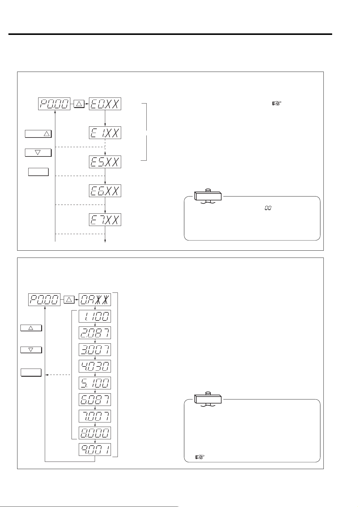
(2) How to Display Shutdown History
Discharge pressure display
SELECT/WIDE
Press once to go to
the next item.
Press once to go to
the previous item.
Return to discharge
pressure display.
1
2
RESET
SELECT/WIDE
1
Press 8 times.
[Latest shutdown]
[Previous shutdown]
XX : Shutdown code
[Oldest shutdown]
History consists of 6 date items.
Not used (display only)
Not used (display only)
To display of various settings
Use the following procedure to display shutdown history.
① Press the SELECT/WIDE button 8 times. “E0.” is the
displayed with the shutdown code (
Section 4). “0”
indicates the most recent shutdown. (The display
automatically changed to “E.0” when shutdown or alarm
occurs.)
② Press the SELECT/WIDE button. “E1.” is displayed along
with the shutdown code. “1” indicates shutdown that
occurred previously. Six items of data (0 to 5) are
recorded. “E5” indicates the oldest shutdown.
③ Press the RESET Button. The screen is returns to the
operation status.
IMPORTANT
If the shutdown code “XX ”is “ ”, it Indicates that
there is no shutdown history. Also, when anything
other than shutdown history is displayed without
shutdown resetting, the display is return to the latest
shutdown history in 3 minutes.
(3) How to Display Various Settings (Perform operation only when confirmation is
necessary.)
Dischargepressuredisplay
1
Proceeds by 1
each time pressed.
2
Returns by 1 each
time pressed.
RESET
Returns to
discharge pressure.
SWITCHDISPLAY
1
Press16times.
No.0 : Control status
A : Capacity control type
No.1 : Start pressure 1
100 : 100psi
No.2 : Recover pressure 1
087 : 87psi
No.3 : Pressure differential 1
007 : 7psi
No.4 : ECOMODE
Cycle time
30 second
No.5 : Start pressure 2
100 : 100psi
No.6 : Recover pressure 2
087 : 87psi
No.7 : Pressure differential 2
007 : 7psi
No.8 : Instantaneous power
interruption (IPI) setting
Invalid
:
000
No.9 : Compressor address
001 : No.1
Use the following procedure to display capacity control type
and pressure setting values for confirmation.
① Press the SELECT/WIDE button 16 times. “0.A**” is
then displayed on the screen. The content of “**” varies
depending on specifications. “A” may be “L” or “U”
depending on capacity control specifications.
② Consists of items 0 - 9. Pressure setting status and
optional pressure setting 2 can be confirmed each time
the SELECT/WIDE button is pressed.
③ Press the RESET Button. The screen is returns to the
usual discharge pressure display.
IMPORTANT
Symbol displayed at No. 0 and corresponding capacity
control type
A: AUTO function setting
L: Fixed speed type setting
(INTE …Load/unload operation)
U: Vtype setting (AUTO function canceled)
(
3.3.5 and 8.4)
26
3. OPERATING PROCEDURE [How to Use the Digital Monitor]
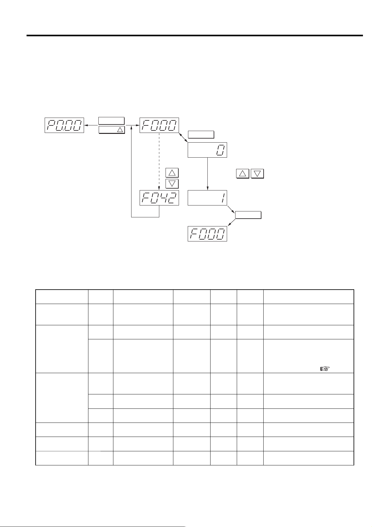
3.4.2 How to Set Control Functions
■ Various settings (instantaneous power interruption (IPI), remote operation, capacity control
setting, pressure setting, etc.)
Switches the display from monitor mode to setting mode (F mode).
RESET
SELECT/WIDE
HolddowntheRESET
buttonandpressthe
SELECT/WIDEbutton
for3secondsor
moretochangeto
theFmode.Perform
sameoperationto
return.
1
Displays000thitemofFmode.
FUNC
SwitcheseachtimeFUNCispressed.
SeetheFmodetableformoredetail.
1
2
Forward
Back
Usebuttonstochangethevalue.
Displayssettingvalue.
F000:(0:SetsStandaloneoperation.)
2
1
F000:(1:Setsmultipleunitcontrol.)
STR
Back
PressSTRtostorethesetting.
Setting can be changed and memorized from the digital monitor without opening the control panel.
■ F Mode table
Function
Multiple unit control
setting
Instantaneous power
interruption (IPI)
restart setting
Remote operation
setting
7 segment
display
Item Range
F000 Control setting 0 - 1 1 0
F002
Instantaneous power
interruption (IPI) setting
0 - 1 1 0 0: Valid, 1: Invalid
Instantaneous power
F003
interruption (IPI)
1 - 5 1 sec 1
detection period setting
F005
F006
F007
Remote control switch
method
Remote operation
method
Remote shutdown
recovery
0 - 3 1 0
0 - 1 1 0 0: Pulse input, 1: Level input
0 - 1 1 0 0: Invalid, 1: Valid
Precision/
unit
Default Remarks
0: Stand alone operation,
1: Multiple unit control
(communication supported)
When the IPI function is available,
instantaneous power interruption is
detected between 20 ms and the
setting detection period set here, and
air compressor restarts. (
0: REMOTE button,
1: Local, 2: Remote,
3: Selectable by external contact
3.4.5).
AUTO setting F011 AUTO operation enabled 0 - 1 1 0 0: Valid, 1: Invalid
Capacity control F018
Function setting
(option)
F021 Pressure control system 0 - 2 1 0
Cut-in/Cut-out pressure
selection
0 - 2 1 0
0: Combination 1, 1: Combination 2,
2: Selectable by external contact
0: Built-in sensor, 1: External contact,
2: Selectable by external contact
27
3. OPERATING PROCEDURE [How to Use the Digital Monitor]
Function
Pressure
setting 1
※2
V type
Pressure
setting 2
※2
Pressure
setting 1
※2
100 / 125 psi (0.69 / 0.86 MPa) specifications
Fixed
speed
type
Pressure
setting 2
※2
7 segment
display
F022
F023
F024
F025
F031
F032
F033
F034
F023
F024
F025
F032
F033
F034
Item Range
Control pressure
setting 1 psi (MPa)
Cut-out pressure 1
psi (MPa)
Cut-in pressure 1
psi (MPa)
Restart pressure 1
psi (MPa)
Control pressure2
psi (MPa)
Cut-out pressure 2
psi (MPa)
Cut-in pressure 2
psi (MPa)
Restart
pressure 2
psi (MPa)
Cut-out pressure 1
psi (MPa)
Cut-in pressure 1
psi (MPa)
Restart pressure 1
psi (MPa)
Cut-out pressure 2
psi (MPa)
Cut-in pressure 2
psi (MPa)
Restart
pressure 2
psi (MPa)
71 〜 125
(0.5 〜 0.86)
71 〜 128
(0.5 〜 0.88)
71 〜 122
(0.5 〜 0.84)
71 〜 122
(0.5 〜 0.84)
71 〜 125
(0.5 〜 0.86)
71 〜 128
(0.5 〜 0.88)
71 〜 122
(0.5 〜 0.84)
71 〜 122
(0.5 〜 0.84)
71 〜 100 [125]
(0.5 〜 0.69 [0.86])
73 〜 86 [110]
(0.5 〜 0.59 [0.76])
73 〜 86 [110]
(0.5 〜 0.59 [0.76])
73 〜 100 [125]
(0.5 〜 0.69 [0.86])
73 〜 86 [110]
(0.5 〜 0.59 [0.76])
73 〜 86 [110]
(0.5 〜 0.59 [0.76])
Precision/
unit
1psi
(0.01MPa)
1psi
(0.01MPa)
1psi
(0.01MPa)
1psi
(0.01MPa)
1psi
(0.01MPa)
1psi
(0.01MPa)
1psi
(0.01MPa)
1psi
(0.01MPa)
1psi
(0.01MPa)
1psi
(0.01MPa)
1psi
(0.01MPa)
1psi
(0.01MPa)
1psi
(0.01MPa)
1psi
(0.01MPa)
Default Remarks
125
(0.86)
128
(0.88)
120
(0.83)
120
(0.83)
125
(0.86)
128
(0.88)
120
(0.83)
120
(0.83)
100 [125]
(0.69 [0.86])
85 [110]
(0.59 [0.76])
85 [110]
(0.59 [0.76])
100 [125]
(0.69 [0.86])
85 [110]
(0.59 [0.76])
85 [110]
(0.59 [0.76])
※Setting can be altered at
any time.
※Setting can be altered at
any time.
Shutdown history clear
F041 (*1)
History clear
0 〜 1
10
0:Enter, 1:History clear
Note:
※ Setting of the items without ※ in remarks can be memorized while the air compressor is stopped.
*1: When set to “1”, history is cleared. After clearing, the value is automatically reset to “0”.
*2: Refer to the below table about the Capacity control pressure setting conditions.
Do not change the setting of F items that are not specified in the table above.
● Capacity control pressure setting conditions
Type Setting conditions (Example of Pressure setting 1)
Fixed-speed
Variable-speed
Note 1: The same setting condition is applied for Pressure Setting 2 (F031 to F034).
IMPORTANT
1. Pressure setting when minimum air receiver tank is installed ( 5.4.4)
Vtype : Pressure differential between cut-out and cut-in shall be 7 psi (0.05 MPa) or more, and pressure differential between
cut-out and target shall be 3 psi (0.02 MPa) or more.
Fixed speed type : Pressure differential between cut-out and cut-in shall be 15 psi (0.1 MPa) or more.
2. External selection of Cut-in/Cut-out pressure combination 1 or 2 is an option. (F018-2)
① F023 shall be set F024 +3 psi (0.02 MPa) or higher, and F025+3 psi (0.02 MPa) or higher.
① F023 shall be set F022+3 psi (0.02 MPa) or higher.
② F024 and F025 shall be set F022 or lower.
28

3. OPERATING PROCEDURE [How to Use the Digital Monitor]
3.4.3 Change of Pressure Setting
Pres.
setting1
FUNC
1
2
Pressthebutton.
Change
values.
Pressthebutton.
STR
3.4.4 Change of Capacity Control Type
AUTOsetting
FUNC
(Initialvalue:0)
1
2
Pressthebutton.
Change
values.
STR
Pressthebutton.
SetAUTOOFF.
Use the following procedure to change the pressure
setting of the capacity control system.
① Switch the display from monitor mode to setting
mode (F mode).
② Set Pressure Setting 1 in F mode.
(
3.4.2)
IMPORTANT
For operation procedure, refer to the various settings.
After entering setting values, be sure to press the
STORE button and return to the monitor mode.
Make sure to press the STORE button to memorize
the setting value.
AUTO (automatic motor stop/restart function) can be
selected properly.
① Switch the display from monitor mode to setting
mode (F mode).
② Set 0 (valid) or 1(invalid) while the air compressor is
stopped.
Capacity control type AUTO ON AUTO OFF
F011 0: Valid 1: Invalid
Digital monitor display 0. AXX0. UXX
After setting change, confirm the capacity control type
by checking the settings on the digital monitor
3.4.1 .
(
(
3.4.7, 3.4.8 and 8.4)
3.4.5 Restart for Instantaneous Power
Interruption
RUNNINGMODE
REMOTE
LOAD
SHUTDOWN
2
IPI is standard function. IPI can be canceled by F002.
refer to the page 27.
START
②③
POWER
AUTOSTART
STOP
UNLOAD STOP
③
In item F018, pressure setting 1 and 2 can be switched.
① This function is available for IPI between 20 ms and
the set value (F003: 1 to 5 sec).
② When IPI occurs , the air compressor stops and the
START light turns of f.
③ After power recovers within F003 set condition, the
AUTO light blinks and the START light turns ON
(glowing) to inform that the air compressor is
waiting for restarting from IPI.
④ The air compressor restarts 15 seconds after power
recovers.
IMPORTANT
(1) IPI means that the power voltage drops to zero (0)
instantaneously.
(2) For the IPI time of less than 20 ms, the air compressor
continues to run.
(3) For the IPI time of more than the setting, the air
compressor judges it as a power failure; the air
compressor stops but does not restart automatically.
Press the START button to restart the air compressor.
29

3. OPERATING PROCEDURE [How to Use the Digital Monitor]
3.4.6 Remote Operation Setting
The REMOTE button on the instrument panel sets
(1) Remote setting by instrument panel
On
(2) Remote setting fixed
REMOTE
IMPORTANT
● When F001 is set to “1:Multi unit control”, remote
operation is selected automatically and the REMOTE
light turns ON (blinking).
● Remote/ local setting change from the setting mode (F
mode) can be memorized while the air compressor is
stopped.
● When the remote operation is active, the air
compressor still can be stopped locally by pressing the
STOP button on the instrument panel.
On
(3) Remote setting by external operation button
Blinking
Local setting
Off
remote operation as (1). In addition, remote operation
can be set by (2) and (3).
(1) To change the Local or remote operation by
REMOTE button on the instrument panel
① Press the REMOTE button.
② REMOTE light turns ON (glowing) to indicate the
remote operation is effective.
③ To return to local operation mode, press the
REMOTE button again.REMOTE light turns OFF
to indicate the remote operation is ineffective.
(2) To fix the remote operation
① Switch the display from monitor mode to setting
mode (F mode).
Remote
control
switching
FUNC
(Initialvalue:1)
1
Alter
values.
2
Pressthebutton.
STR
Pressthebutton.
Setto"Remote
settingfixed."
② Change the value of F005 to “2: Remote”.
(
3.4.2)
③ REMOTE light turns ON (glowing) to indicate the
remote operation is effective.
(3) To change the Local or remote operation by
external contact.
( Contact the local HITACHI distributor/master
dealer or representative office.)
① Connect the external contact wiring. (
8.2)
② Switch the display from monitor mode to setting
mode (F mode).
③ Change the value of F005 to “3: Selectable by
external contact”. (
3.4.2)
④ Short the external contact to set the remote
operation.
⑤ REMOTE light turns ON (glowing) to indicate the
remote operation is effective.
30

3. OPERATING PROCEDURE [How to Use the Digital Monitor]
3.4.7 Pressure Setting Switching Function
Two different combinations of cut-out pressure and cutin pressures can be used: Pressure combination 1 and
2. The Combination 1 is used as the standard daily
settings. The Combination 2 is used for a limited time
period where different settings may be required, and
can be set for a certain time
3.3.5 and 3.4.2)
(
Load light turns on (glowing) during load and turns off
during unload when pressure combination 1 is
selected. Load light turns on (blinking) during load and
turns off during unload when pressure combination 2 is
selected. ECOMODE and PQ wide mode is invalid
during pressure combination 2 is activated.
External selection of Cut-in/Cut-out pressure
combination
local HITACHI distributor/master dealer or
representative office.
1 or 2 is an option. (F018-2). Contact the
Cut-out
press.1
Cut-out
press.2
Cut-in
press.1
Cut-in
press. 2
Line pressure
Load light
External contact (option)
Load Unload
Glow OFF Glow
Energy Saving Effect
Glow
Blink
Time
BlinkOFF OFF OFF
ONOFF
Blink
3.4.8 ECOMODE Function (only for Fixed speed type)
(1) Setting of ECOMODE (Energy Saving Mode)
ECOMODE is set OFF on factory setting. See
SELECT/WIDE button in page 13 to be activated.
This function enables a power saving operation by
reducing the cut-out pressure to a preset target
value, based on if the load/unload cycling interval is
longer than the set interval. If the cycling interval
time is longer than set interval, the system reduces
the cut-out pressure to a target so as to make the
cycling interval closer to the set value. Minimum
cut-out pressure is cut-in pressure + 7 psi (0.05
MPa). Minimum cycle time is 30 seconds.
If the cycle time is 30 seconds or more, SELECT/
WIDE light turns on (blinking) to indicate
ECOMODE is effective. By setting the ECOMODE
to ON, the display’s TYPE field shows SAVE for a
power saving operation. (
3.3.2)
(2) Caution for using ECOMODE
Larger than standard air receiver tank is required to
keep the ECOMODE effective. (
5.4.4).
Factorysetting
Pressure differential between cut-in and cut-out pressure: 15 psi (0.1MPa)
Allowable pressure differential for ECOMODE: 7 psi (0.05MPa) (unable to change)
Minimum cycle time: 30 seconds
RUNNING CONTROL
ALAR M
FUNC
Cut-out
pressure
Cut-in
pressure
Line pressure
RESET
ON : The light blinks.
OFF : The light turns off.
SELECT/WIDE
REMOTE
STR
1
SELECT/WIDE
Press the button for 7 seconds or more to set.
Energy Saving Effect
Load Unload
Time
SELECT/WIDE
1
Cut-out is
automatically
reduced.
31

3. OPERATING PROCEDURE [Daily Operation of Air Compressor]
3.5 Daily Operation of Air Compressor
CAUTION
● When using the air compressor, do not raise the discharge pressure excessively. Operating the air
compressor over the rated pressure can result in main motor overload, shutdown of the airend and/or
damage of parts.
● If the air relief valve has blown or a protective device has shutdown the air compressor, investigate
the cause of and take corrective action. If there are any questions or comments in taking these
actions, contact the local HITACHI distributor/master dealer or representative office.
3.5.1 Preparing the air compressor
RUNNING CONTROL RUNNING MODE
SELECT/WIDE
1
REMOTE
LOAD
SHUTDOWN
2
ALARM
RESET
FUNC
REMOTE
STR
③
3.5.2 Starting the air compressor
②
POWER
AUTO START
STOPSTART
UNLOAD STOP
① Connect the power.
② Check the POWER light and LCD, and verify that:
the POWER light is ON, and the monitor display has
-
appeared.
③ Check the oil level gauge, and verify that:
-
the oil stays around the upper or lower red lines of the oil
level gauge.
④ Close the petcock and water relief valve.
Water-Cooled
⑤ Open the cooling water valve.
IMPORTANT
Verify that the oil stays between the upper and lower red
lines of the oil level gauge while air compressor is running.
Since the oil comes back to the oil case after the air
compressor stops, the oil level during air compressor
running is lower than during air compressor stopping.
① Open the discharge stop valve.
32
③④
DIS.PRESS:100psi
INTSTG.P: 22psi
OILPRESS: 22psi
CLTPRESS: **psi
RUNNING CONTROL RUNNING MODE
SELECT/WIDE
1
REMOTE
LOAD
SHUTDOWN
2
AUTO START
UNLOAD STOP
ALARM
RESET
FUNC
REMOTE
STR
②
①
[Rear View]
② Press the START button.
POWER
STOPSTART
-
The compressor switches to full load operation within 20
seconds for the Fixed speed type and within 10 seconds for
the V type.
③ Check the LCD monitor, and verify that:
-
the oil pressure is 12 psi (0.08 MPa) or more.
④ Check the LCD for a gradual rise of the discharge
air pressure, and verify that:
-
the maximum discharge air pressure is less than the rated
pressure.

3. OPERATING PROCEDURE [Daily Operation of Air Compressor]
3.5.3 While Operating the Air Compressor
MONITOR
AUTO
MONITOR
MENU
+/−
UP/
DOWN
SET
RUNNINGCONTROL
ALARM
FUNC
RESET
STR
[×10h]
SELECT/WIDE
1
RUNNINGMODE
REMOTE
LOAD
SHUTDOWN
2
STARTREMOTE
POWER
AUTOSTART
STOP
UNLOAD STOP
① Check the LCD for operating pressures and
temperatures, and verify that:
Interstage pressure (INTSTG P), oil pressure (OIL PRES),
-
1st stage discharge air temperature (DIS. TEMP 1), 2nd
stage discharge air temperature (DIS. TEMP 2), oil
temperature (OIL TEMP) and 2nd stage suction
temperature (2ND SUCT. T) stays within the normal range.(
6.1.3)
㻞㻜㻝㻞䠋㻜㻥䠋㻜㻝 㻝㻥䠖㻜㻞
㻼㻾㻱㻿㻿㼁㻾㻱
㻵㻺㼀㻿㼀㻳䠊㻼䠖 㻌㻌 㻞㻥㼜㼟 㼕
㻻㻵㻸㻌 㻼㻾㻱㻿䠖 㻌㻌 㻝㻡㼜㼟 㼕
㻯㻸㼀䠊㻼㻾㻱㻿䠖 㻖䠊 㻖㻖 㼜 㼟 㼕
㼀㻱㻹㻼㻱㻾㻭㼀㼁㻾㻱
㻰㻵㻿䠊㼀㻱㻹㻼㻝䠖 㻟㻞㻜䉣
㻰㻵㻿䠊㼀㻱㻹㻼㻞䠖 㻟
㻻㻵㻸㻌 㼀㻱㻹㻼䠖 㻟㻢䉣
㻯㻸㼀䠊㼀㻱㻹㻼䠖 㻖㻖 㻖䉣
㻞㻺㻰㻌㻿㼁㻯㼀䠊㼀䠊䠖 㻜㻤䉣
㻹㻭 㻵 㻺㼀 㻱 㻺㻭㻺㻯 㻱
㻴㻾䠊㼀㻻 㻌 㻹㻭 㻵 㻺㼀 䠖 㻜 㻜 㻜 㻜 䡄
㻺㻱㼄㼀㻌 㻹㻭 㻵 㻺㼀 䠖 㻖 㻖 㻖 㻖
㻟㻤䉣
㻝
㻝
3.5.4 When Stopping the Air Compressor
RUNNING CONTROL RUNNING MODE
REMOTE
②
DIS.PRESS: 100psi
INTSTG.P: 22psi
OILPRESS: 22psi
CLTPRESS:**psi
ALARM
RESET
FUNC
REMOTE
SELECT/WIDE
STR
1
①
SHUTDOWN
2
LOAD
POWER
AUTO START
STOPSTART
UNLOAD STOP
② Verify that the intercooler/aftercooler condensate
drain is discharged intermittently when the air
compressor is loading.
③ When the air compressor is unloading, condensate
drain is discharged one (1) second a five (5)
minutes.
① Press the UNLOAD STOP button to stop the air
compressor.
The air compressor unloads for 5 minutes and stops.
(In the case of an emergency, press the
EMERGENCY STOP button.)
② Check the pressure after the air compressor stops
running.
-
Both oil pressure and interstage pressure shall be 0 psi
( The pressures may be 1 psi depending on operation
conditions.)
③
④
[Rear View]
③ Check the sight glass on the control line filter to
confirm that drain is properly discharged. (Fixedspeed type)
④ Close the valve on the discharge side.
Water-Cooled
⑤ Close the cooling water stop valve. Open the
petcock and cooling water drain valve to drain the
cooling water from the air compressor. Be careful
not to damage the parts, such as coolers and casing,
by cooling water freezing.
33

3. OPERATING PROCEDURE [
Daily Operation of Oil Mist Remover
]
3.6 Daily Operation of Oil Mist Remover
3.6.1 When Setting 3.6.2 When Stopped
Make sure that the vacuum indicator shows a red mark.
8
φ
Make sure that the
vacuum indicator does not
show a red mark.
Make sure that the pressure
gauge reads as follows:
Pressure Gauge
51 to 58 psi
Make sure that the
condensate is not
collected in the
filter bowl.
If the condensate is
collected, push up
the cock to drain
the condensate.
Condensate Drain Cock
(see the left drawing)
34

3.7 Adjusting Procedure
3. OPERATING PROCEDURE [Adjusting Procedure]
3.7.1 Adjusting the Suction Bypass
Valve (For Fixed-Speed type)
①④
Suction
throttle
valve
②④
Air intake filter
③
Adjusting Bolt
(Suction Bypass Valve)
Usually keep the bolt
Locknut
Seal washer
tightened, but not
excessively.
① When dust particles accumulate on the valve plate of
the suction throttle valve, the suction vacuum
pressure may drop and eventually causing the
discharge air temperature to rise.
② The first steps to resolve the lower suction vacuum
pressure are as following. If the unloaded interstage
pressure drops as low as -12 psi (-0.08 MPa) or
discharge air temperature is gradually increased.
A) Clean or replace the air intake filter.
B) Clean the suction throttle valve’s valve plate.
③ If the air compressor cannot be shutdown to clean
these parts, turn the adjusting bolt (the suction
bypass valve) counterclockwise to open. This will
allow the air intake and increase the discharge air
pressure to be greater than -12 psi (-0.08 MPa) when
running unloaded.
④ Replace the consumable parts in the air intake filter
and suction throttle valve with new consumable
parts in accordance with the appropriate
maintenance schedule. (
Section 9)
3.7.2 Regulating the Oil Pressure
Oil Relief Valve
IMPORTANT
The interstage pressure of as low as
unloading period may increase the discharge air
during
temperature.
-12 psi (-0.08 MPa)
① Use the oil relief valve to regulate the oil pressure.
To regulate the oil pressure, open the oil relief valve
cap, loosen the lock nut, and turn the regulating bolt
to keep the oil pressure at the specified 18 psi to 23
psi (0.12 to 0.16 MPa).
18 psi to 23 psi (0.12 to 0.16 MPa) when the ambient
・
temperature is 68 degree F (20 degree C) or higher.
・ 20 psi to 26 psi (0.14 to 0.18 MPa) when the
ambient temperature is 68 degree F (20 degree C)
or lower.(for V type, adjust at the maximum
operating frequency.)
② Turn the regulating bolt clockwise to increase the
oil pressure and vice versa.
③ Tighten the locknut and replace the cap.
IMPORTANT
If the oil pressure is reduced to the specified or lower, the
oil pressure sensor detects it and shutdown the air
compressor.
specified value for each type of air compressor
4. TROUBLESHOOTING to the
35

4. TROUBLESHOOTING
CAUTION
If a shutdown, alarm, problem or failure occurs, investigate the cause and take proper corrective action
before restarting. If there is any questions or comments, contact the local HITACHI distributor/master
dealer or representative office.
4.1 Protective Device
The air compressor is provided with the protective devices listed below. If shutdowns are detected by these protective
devices, remove the cause with referring to the LCD monitor indication and this manual, and then press the RESET
button to clear the shutdown indication. Depending on the type of shutdown, contact the local HITACHI distributor/
master dealer or representative office.
■ When connecting the power
Heading Trouble Description
POWER
LCD Indication
Reversal phase connection
(Note 2)
Phase-lacking connection
Instantaneous power interruption
Brief instantaneous power
interruption
What and How to Detect
Detected for 3
seconds after
connecting the power
Power interruption for 1 to 5 sec.
Power interruption for
1 sec or less.
Failure
Light
SHUTDOWN
Blinks
-
Detector
CPU
(Note 1)
CPU
(Note 1)
CPU
CPU
Shutdown
Ye s
Ye s
Restart
Restart
What Actions to Take
Reconnect the power cable tightly, check the
power supply and incoming power for loose
connections and change the connection
location of 2 of the 3 phases, be sure to follow
all electrical safety procedures.
Reconnect the power cord tightly, check the
power supply, and take a corrective remedy.
3.4.5
3.4.5 04 E0.04
4.2.
How to
Reset
Press RESET
button.
-
History
code
01 E0.01
02 E0.02
03 E0.03
Error
code
■ During Operation
LCD Indication
Heading Trouble Description
1st stage discharge air temperature
(HIGH DIS. TEMP. 1)
1st stage discharge air temperature
2nd stage discharge air
temperature
(HIGH DIS. TEMP. 2)
Interstage pressure
[Fixed speed type]
Interstage pressure 44psi 0.30MPa or higher
2nd stage suction air temperature
(2ND SUCT. TEMP)
SHUTDOWN
FAILURE
INV STOP
Oil temperature
(OIL HIGH TEMP)
Oil pressure
[Fixed speed type]
Oil pressure
(OIL-LOW PRESS)
Answer error of 52
Overloading(main motor)
[Fixed speed type]
Overloading (main motor) Detected during operation
Overloading (auxiliary motor)
Answer error of 52
Answer error of 42
[Fixed speed type]
Inverter tripping or main
motor overloading with
automatic retrials.
What and How to Detect
About 437 [419]℉
225 [215]℃ or higher
The discharge temperature at 1st
stage rises above the below settings.
100 psi model
0.69 MPa model
125 psi model
0.86 MPa model
● For working pressure of
100psi 0.69 MPa : About 446[428]℉
230 [220]℃ or higher
● For working pressure of
125psi 0.86 MPa : About 500[482]℉
260 [250]℃ or higher
39psi 0.27MPa or higher
163 [158]℉
73 [70]℃ or higher
163 [158]°F
73 [70]℃ or higher
12 psi 0.08 MPa or lower
● For fi xed Speed type:
12 psi 0.08 MPaor lower
● For Vtype:12psi 0.08 MPa or
lower (operating Freq. 45 Hz or
higher) 6psi
(operating Freq. Less than 45 Hz)
239℉ 115℃ or higher
(main motor bearing)
239℉ 115℃ or higher
(main motor bearing)
Detected during operation
Detected during
running.
Detected after shifting to △
running.
Failure signal from inverter
about 446°F
[about 419°F]
about 230℃
[about 215℃]
0.04MPaor lower
Failure
Light
SHUTDOWN
Blinks
SHUTDOWN
Blinks
SHUTDOWN
Blinks
SHUTDOWN
Blinks
SHUTDOWN
Blinks
SHUTDOWN
Blinks
SHUTDOWN
Blinks
SHUTDOWN
Blinks
SHUTDOWN
Blinks
Blinks
in red
Blinks
in red
SHUTDOWN
Blinks
SHUTDOWN
Blinks
SHUTDOWN
Blinks
SHUTDOWN
Blinks
SHUTDOWN
Blinks
Detector
Shutdown
Thermistor
Thermistor
Thermistor
Pressure
sensor
Pressure
sensor
Thermistor
Thermistor
Pressure
sensor
Pressure
sensor
Thermo
stat
Thermo
stat
Thermal
relay
Thermal
relay
CPU Yes
CPU Yes
Failure
stop after
CPU
repetition
of retrials.
Ye s
Ye s
Ye s
Ye s
Ye s
Ye s
Ye s
Ye s
Ye s
Ye s
Ye s
Ye s
Ye s
What Actions to Take
4.2
4.2
4.2
4.2
4.2
4.2
4.2
4.2
4.2
4.2
4.2
4.2
4.2
4.2
4.2
4.2
※ The value in the [ ] is for water-cooled model
History
How to
Reset
Press RESET
button.
Press RESET
button.
Press RESET
button.
Press RESET
button.
Press RESET
button.
Press RESET
button.
Press RESET
button.
Press RESET
button.
Press RESET
button.
Press RESET
button.
Press RESET
button.
Press RESET
button.
Press RESET
button.
Press RESET
button.
Press RESET
button.
Press RESET
button.
Error
code
code
55 E0.55
55 E0.55
56 E0.56
52 E0.52
52 E0.52
5B E0.5B
58 E0.58
5C E0.5C
5C E0.5C
51 E0.51
17 E0.17
17 E0.17
53 E0.53
51 E0.51
16 E0.16
44 E0.44
36

■ During Operation
LCD Indication
Heading Trouble Description
Clogging of air intake filter
(AIR FILTER)
1st stage discharge air
temperature (DIS. TEMP. 1)
1st stage discharge air
temperature (DIS. TEMP. 1)
ALARM
2nd stage discharge air
temperature (DIS. TEMP. 2)
2nd stage suction air
temperature (2ND-S. TEMP)
Oil temperature (OIL TEMP)
[Fixed Speed type]
Oil pressure (LOW O.P.)
Load/unload cycle time
over (L COUNT OVER)
What and How to Detect
Pressure differential of -0.72
psi 4.98 kPa or more
About 428 [410]℉
220 [210]℃ or higher
The temperature detected at
1st stage rises above the below
settings.
100 psi model
0.69MPa model
125 psi model
0.86MPa model
● For working pressure of
100psi 0.69MPa model: About
437 [419]℉ 225 [215]℃ or higher
● For working pressure of
125psi 0.86MPa model : About
491 [473]℉ 255[245]℃ or higher
about 437℉
[about 410℉]
about 225℃
[about 210℃]
154 [149]℉
68 [65]℃ or higher
154 [149]℉
68 [65]℃ or higher
15 psi 0.10MPa or lower
1,000,000 cycles
Failure
Light
ALARM
Blinks
ALARM
Blinks
ALARM
Blinks
ALARM
Blinks
ALARM
Blinks
ALARM
Blinks
ALARM
Blinks
ALARM
Blinks
4. TROUBLESHOOTING [Protective Device]
Detector
Shutdown
Pressure
differential
sensor
Thermistor
Thermistor
Thermistor
Thermistor
Thermistor
Pressure
sensor
CPU No
What Actions to Take How to Reset
No
No
No
No
No
No
No
9.4
4.2
4.2
4.2
4.2
4.2
4.2
Replace suction throttle valve
consumable parts and Blow
off solenoid valves
Press RESET
button.
Automatically
reset.
Automatically
reset.
Automatically
reset.
Automatically
reset.
Automatically
reset.
Automatically
reset.
Hold down the
REMOTE and
press the
SELECT/WIDE
button
seconds or more.
History
for 7
Error
code
code
21 E0.21
25 E0.25
25 E0.25
26 E0.26
2B E0.2B
26 E0.26
2C E0.2C
59 E0.59
■ Others
LCD Indication
Heading Trouble Description
Battery out (BATTERY OUT)
Scheduling operation error
(SCHEDULE SET ERR)
PROBLEM
Lead/lag operation error
(MULTI-U SET ERR)
RS-485 port error
(COM.ERR STOP) NOTE 3
RS-485 port error
(COM.ERR ALM) NOTE 3
What and How to Detect
Battery voltage low
Start/stop time not set
yet
Setting error
Setting error
Setting error
(ROM1) (RAM1) main
PCB error
(PCB ERR)
board memory error
(ROM2) (RAM2) LCD
board memory error
FAILURE
Interstage pressure sensor error
(PRESS. SNSR ERR 1)
Discharge pressure sensor error
(PRESS. SNSR ERR 2)
Oil pressure sensor error
(PRESS. SNSR ERR 4)
2nd stage inlet
temperature sensor error
PS1 disconnected
PS2 disconnected
PS4 disconnected
TH2 disconnected
(TEMP. SNSR ERR 2)
1st stage outlet
temperature sensor error
TH3 disconnected
(TEMP. SNSR ERR 3)
2nd stage outlet
temperature sensor error
TH4 disconnected
(TEMP. SNSR ERR 4)
Oil temperature sensor error
(TEMP. SNSR ERR 5)
TH5 disconnected
NOTES:
(1) Depends on the specification, reverse phase relay is used.
(2) The air compressor using reverse phase relay, such as for 460 V/60 Hz, indicates a phase-lacking connection as reversal phase.
(3) Communication error details:
Port 1(65) =Main circuit communication (Vtype), Port 2 (66)=Fan inverter communication (Air-cooled model)
Port 3 (67)= LCD communication, Port 4 (68)= Multiple unit control communication, Port 5 (63)= External communication
Failure
Detector
Light
ALARM
CPU No
Blinks
ALARM
CPU No See 3.3.5 (4)
Blinks
ALARM
CPU No
Blinks
SHUTDOWN
Thermistor
Blinks
ALARM
Pressure
Blinks
sensor
SHUTDOWN
CPU Yes
Blinks
SHUTDOWN
CPU Yes
Blinks
SHUTDOWN
CPU Yes
Blinks
SHUTDOWN
CPU Yes
Blinks
SHUTDOWN
CPU Yes
Blinks
SHUTDOWN
CPU Yes
Blinks
SHUTDOWN
CPU Yes
Blinks
SHUTDOWN
CPU Yes
Blinks
SHUTDOWN
CPU Yes
Blinks
Shutdown
What Actions to Take
Disconnect the power and replace the
battery with a new one.
Check the wire and the operation setting
on the instrument panel.
Ye s
Check the wire and the operation setting.
Check the wire and the operation
Ye s
setting.
Disconnect the power and then reconnect the
power. If problem is persists, change the PCB.
Disconnect the power and then reconnect the
power. If problem is persists, change the PCB.
Disconnect the power and check the
pressure sensor wire for tightness.
Disconnect the power and check the
thermistor sensor wire for tightness.
9.4 (12).
How to
Reset
Press RESET
button.
Press RESET
button.
Press RESET
button.
Press RESET
button.
Press RESET
button.
Press RESET
button.4347, 48
Press RESET
button.
Press RESET
button.
Press RESET
button.
Press RESET
button.
Press RESET
button.
Press RESET
button.
Press RESET
button.
Press RESET
button.
History
Error
code
code
64 E0.64
62 E0.62
5B E0.5B
63 65
E0.63 65
〜 68
〜 68
63 65
E0.63 65
〜 68
〜 68
E0.43
47, 48
41, 42 46E0.41,
42 46
33 E0.33
34 E0.34
39 E0.39
32 E0.32
35 E0.35
36 E0.36
37 E0.37
37

4. TROUBLESHOOTING [Troubleshooting of Air Compressor]
4.2
4.2 Troubleshooting of Air Compressor
■ Most common problems, causes and corrective actions are described below.
Phenomenon LCD indication example Cause Corrective remedies
NOT start
<P R O B L E M>
CONNECTION ERR: REV
RES
Press
<P R O B L E M>
CONNECTION ERR: OPEN
Press
after CHK.
RES
after CHK.
1. Power supply switch - OFF.
2. Power – Failed, or power source
voltage - Low.
3. Power cable - In a reversal phase
connection.
4. Power cable - In a phase-lacking
connection.
(Note) See Note (2) in previous
page.
1. Check the power supply switch.
2. Check the power supply.
3. Change 2 of 3 wires of the power
cord.
4. Reconnect the power cord tightly and
check the power supply.
NOTE: Phase-lacking is detectable only
when connecting the power.
Shutdown 1st stage
discharge air
temperature or
interstage pressure
Shutdown –
2nd stage
discharge air
temperature
Shutdown –
2nd stage suction
air temperature
Shutdown –
Oil temperature
Shutdown –
Oil pressure
<S H U T D O W N>
HIGH DIS. TEMP. 1:
Press
<S H U T D O W N>
INTSTG. P:
Press
<S H U T D O W N>
DIS. TEMP.2:
Press
<S H U T D O W N>
HIGH DIS. TEMP. 2:
Press
<S H U T D O W N>
OIL : HIGH TEMP
Press
<S H U T D O W N>
OIL : OIL LOW PRESS
Press
RES
after CHK.
RES
after CHK.
RES
after CHK.
RES
after CHK.
RES
after CHK.
RES
after CHK.
1. 2nd-stage AIR END air intake
effi ciency - Lowered
2. Air intake fi lter - Dirty
3. Temperature of Suction Air-High
1. Check valve – Compressed air
leaked (from the aftercooler to
the air end when unloading)
2. Suction throttle valve - Dirty
[Fixed speed type]
1. Cooling water pump – failed, or
cooling water temp. – Fluctuating
(Water-cooled model)
2. Intercooler – Dirty
1. Oil cooler – Dirty
2. Room temperature – High
3. Oil temperature control valve –
Failed
1. Oil strainer and/or oil fi lter – Dirty
2. Oil level – Low
1. Clean or change the air intake fi lter
2. Lower the suction air temperature
1. Replace the check valve.
2. Clean the Suction throttle valve.
[Fixed speed type]
Note: For information about the Suction
bypass valve,
3.7)
1. Check the cooling water system
(Water-cooled model).
2. Clean the intercooler
1. Check the oil cooler.
2. Lower the room temperature.
3. Check the oil temperature control
valve.
1. Clean the oil strainer
2. Replace the oil fi lter.
3. Add the oil.
Shutdown –
Motors overload
Shutdown –
Inverter
38
<S H U T D O W N>
OVERLOAD : MAIN
Press
<S H U T D O W N>
OVERLOAD : SUB
Press
RES
after CHK.
RES
after CHK.
[Water-cooled type] [Vtype]
<S H U T D O W N>
CONTACTOR ERR : 52
Press
<F A I L U R E>
SYSTEM RETRY :
RES
after CHK.
1. Power supply voltage – Low
2. Discharge air pressure – Too high
3. Power supply - Imbalance
4. Motor Insulation - Failure
1. Power supply voltage – Low
2. Cooling fan motor – Failed
3. Power supply - Imbalance
4. Motor Insulation - Failure
1. Power supply voltage – Low or in
unbalance
2. Discharge air pressure – Too high
3. Main motor – Overloading
NOTE: 4th retry action in ten minutes
becomes shutdown failure.
1. Rectify the power supply voltage.
2. Check the suction throttle valve
[Fixed speed type]
3. Check the capacity control system.
4. Check the insulation resistance.
1. Rectify the power supply voltage.
2. Check the cooling fan motor.
(Measure insulation resistance etc.)
1. Rectify the power supply voltage.
2. Check the capacity control system.
3. Measure insulation resistance etc. or
check the main motor.

4. TROUBLESHOOTING [Troubleshooting of Oil Mist Remover]
4.3 Troubleshooting of Oil Mist Remover
Problems and actions to be taken are as follows.
① The vacuum indicator shows a red mark
The pressure gauges reads zero (0) MPa. The control air is not supplied.
NO
Pressure setting of the regulator is lower ?
NO
Pressure of a control air is lower than the regulator
setting value ?
NO
The gear case or gear case vent pipe has a leak
(for example, the oil filling port plug on the gear case is not tight).
NO
The solenoid valve may have problem or the remover
element may be dirty.
If the solenoid valve has no problem replace the element.
YES
YES
YES
YES
Reset the regulator to a proper pressure.
Clean the filter.
Maintain the pressure of a control air at the regulator
setting value.
- Tighten every screw and plug to remove all leaks.
- Make sure that the OMR relief valve is closed.
② The OMR relief valve opens immediately when starting the air compressor (the control air pressure is still
low) or when the DSP has stopped. This is a normal occurrence.
The OMR relief valve is dirty or stuck open by a foreign
object.
NO
Go to the procedure ①. The vacuum indicator shows a
red mark. (Gear case has a positive internal pressure.)
NOTE:
The OMR relief valve opens immediately when starting the DSP (the control air pressure is still low) or when the DSP has
stopped. This is a normal occurrence.
YES
Disassemble and clean the OMR relief valve.
Replace if necessary.
③ Oil is vented through the ejector’s compressed air outlet (the separated oil is not being recovered).
Accumulated oil is visible in the tube between the
element housing and the fl oat trap.
No
Upper or lower packing is not seated properly on the
element ?
No
Control air contains oil ? Check the control air for oil contents.
No
Element may be dirty.
Inspect the element and replace if necessary.
YES
YES
YES
Clean the nozzle of the fl oat trap.
Reinstall the element, seating the packing properly for a
maximum sealing performance.
④ Oil pressure is low (oil pump may be inhaling air).
Problem of compressor (dirty oil filter, low oil pressure due
to oil leakage, failure of oil pump or OMR relief valve, etc.)
NO
Foreign matter in float trap nozzle (Check for a large
amount of air sucked from the oil collecting pipe to oil
pump suction side.)
NOTE:
The oil mist remover makes the gear case internal pressure negative during operation, reducing the pressure by 0.7 to 1.5 psi
(0.005 to 0.01 MPa). This is not unusual; reset the oil pressure on the air OMR relief valve.
YES
YES
Perform necessary adjustment or replacement.
Disassemble and clean the float trap nozzle and the
float trap.
39

5. INSTALLING AND PIPING THE DSP
5.1 Unpacking the Air Compressor
■ After unpacking the crate, verify that the air compressor is what you have ordered, by referring to Section 15.
“STANDARD SPECIFICATIONS and also by checking the model nameplate.
■ Verify that product is not damaged or deformed during transpor tation.
Model Nameplate
Output (kW)
Model
Frequency (Hz)
Main Standard Accessories
Foundation bracket, Foundation bolt/nut (M20) 4 pieces
Bolt (M20) for Foundation bracket 4 pieces
Fork slot cover 4 pieces
Bolt (M6) for Fork slot cover 8 pieces
Motorized isolation valve 1 piece
Motorized water isolation valve (※) 1 piece
Handle 1 piece
※ Provided only with
Water-Coole d
.
5.2 Conveying the Air Compressor
■ With a Forklift ■ With a Shop Crane
Pad
Use a pad to protect
the enclosure.
Keep the distance of
59 inch (1500 mm)
or more.
Use a pad to
protect the
enclosure panel.
Use the strong wires.
Adjust the wire length to
keep the balance when
hoisting it.
Use the attached
tie frame.
Model Total Mass
DSP-90A6N
DSP-110A6N
DSP-90W6N
DSP-110W6N
Model Total Mass
DSP-90VA6N
DSP-110VA6N
DSP-90VW6N
DSP-110VW6N
5,250 lbs
(2,380kg)
5,600 lbs
(2,540kg)
5,030 lbs
(2,280kg)
5,380 lbs
(2,440kg)
5,470 lbs
(2,480kg)
5,580 lbs
(2,530kg)
5,250 lbs
(2,380kg)
5,360 lbs
(2,430kg)
Use the adhesive tapes
to prevent the front door
from detached during
conveyance.
Lift the unit balanced.
Use the adhesive tapes
to prevent the front door
from detached during
conveyance.
■ After installing the air compressor, plug the fork slots
with the fork slot covers.
Common Base
Fork Slot Cover
Bolt (M6×15)
40

5. INSTALLING AND PIPING [Installing the Air Compressor]
V
5.3 Installing the Air Compressor
(Selection of a proper installation location is essential to a long service life for the Air Compressor.)
WARNING
1. Keep flammable solvents or any other hazardous chemicals away from the air compressor. Such
chemicals may be ingested into the air compressor and could cause an explosion during the
compression process.
2. Do not use fire near the air compressor; otherwise the sparks may enter the airend and burn it internally.
■ Install the air compressor in a bright, wide, and airy room as follows:
entilating fan
If you install the air
compressor in a small room,
provide a ventilating fan to
keep the room temperature
at 104℉ (45℃) or lower.
Maintenance Space
Plug the fork slots with
the fork slot covers
(standard accessory)
Maintenance Space C
Foundation
Provide a vibration-absorbing
mat if the foundation is
vibrative. If it is too vibrative,
look for another dequate
Maintenance Space B
Maintenance Space A
※ Keep spaces of indicated in the
Maintenance Space inches (mm)
■ Install the air compressor in a dry and dust-free room, and avoid the following.
Raindrops, Basements, Steam
Metals, Sand, Other Hard Materials
()
table below, or more for daily
operation and periodical
maintenance and for keeping the
enough cooling air for coolers.
Item
A
Front
B
Right
C Rear
D Left
Air-cooled model
39 (1000) 47 (1200)
47 (1200) 31 (800)
39 (1000) 39 (1000))
39 (1000) 39 (1000)
Water-cooled model
Harmful Gases
Toxic gases such as chlorine gas, hydrogen
sulfide gas, sulfurous acid gas, high consistency
ozone, ammonia gas
Causes electric leak, generation of
drain/rust, microcomputer malfunction.
■ Install the air compressor on a level floor.
To ensure an appropriate amount of oil
To prevent noise and vibration
Causes motor insulation failure, bearing
damage, microcomputer malfunction.
Prohibited
Do not set the air
compressor on blocks.
CAUTION
Causes deterioration of oil, wear of cooler,
detachment of coating from rotor surface.
Do not install the air compressor near a wall.
■
Doing this may cause the operating noise
to resonate and increase the noise levels.
● Install the air compressor indoors. Installing it outdoors may lead to damage of the airend due to
water vapor, dust, etc.
● The air compressor installation room should have an air intake opening, an air exhaust opening and
have good ventilation. If the room is poorly ventilated, hot air exhausted by the air compressor may
cause the room temperature to rise excessively and lead to damage of the air compressor.
41

5. INSTALLING AND PIPING [Piping the Air Compressor]
5.4 Piping the Air Compressor
5.4.1 General Instructions
① Use the degreased pipe as a plant airline pipe.
② Install an isolation stop valve on the compressed air
outlet pipe (see figure below). Close the isolation
stop valve when stopping the air compressor.
Stop Valve
Discharge Air
③
Using flange joint to connect the air compressor to an
existing compressed air piping installation allows for
minimal disassembly of the enclosure panels (see
figure above).
⑦ If the air compressors discharge pipe is connected to
the main compressed air piping, run the discharge
up above the main compressed air piping and then
down into the top of the main compressed air piping
(see figure below). This prevents the backflow of
condensate.
5.4.2 Parallel piping
Stop Valve
Main compressed air pipe
From air compressor
Motorized isolation valve
Opened
④ If the plant compressed air piping installation is
extensive in length, using a larger diameter pipe
assists in lowering pressure drop throughout the
piping system.
⑤ If there is an area in the compressed air piping that
is concaved or vertical (see figure below), provide a
condensate drain valve at its bottom as a drip leg.
Stop Valve
Condensate Drain Valve
IMPORTANT
Prevent the backflow of condensate from the plant
compressed air system back to the air compressor.
If the compressed air piping near the air compressor is
⑥
to be elevated, keep a space of 20inches (500mm)
between the elevated piping and the enclosure for ease
of maintenance (see figure below)
20inches or more
(500mm)
Discharge
Air
Operating DSP
Air Receiver Tank
Stop Valve
Motorized isolation valve
Closed
Non-Operating DSP
If one air compressor is operated, close the stop valve
of the stopped air compressor. For automatic operation,
such as lead/lag and multi unit controlled, replace the
stop valve to an optional motorized isolation valve.
Ensure that the motorized isolation valve is closed
while the compressor is not running. If you use a
solenoid valve as the automatic stop valve, consult your
Hitachi distributor or local Service Station given on the
rear cover.
Contact the local HITACHI distributor/master dealer
or representative office for more detail.
IMPORTANT
42
As shown in the figure above, when one compressor is
operating and the other is stopped with opening the stop
valve, back pressure is applied to the aftercooler and
check valve of the stopped air compressor. This may
cause more condensate going into the air compressor
and more rusting of aftercooler and check valve.

5. INSTALLING AND PIPING [Piping the Air Compressor]
5.4.3 How to Install Automatic
Discharge Valve
Discharge
Air
Air Receiver Tank
Stop Valve
Pressure
detecting
piping
The air compressor is equipped with AUTO restart/
stop function as a standard function. The pressure for
capacity control is detected at the secondary side of the
motorized isolation valve. Install the motorized
isolation valve and pressure detecting piping (standard
accessory). Connect the pressure detecting piping
from upper side of main piping to pressure detecting
port of the air compressor as above.
Install the pressure detecting piping as close as
motorized isolation valve. The operation with NOT
installed pressure detecting piping results in the air
relief valve action.
IMPORTANT
The motorized isolation valve is closed when the air
compressor is stop. The operation WITHOUT the
motorized isolation valve results in the backflow of
condensate from the plant compressed air system. Then
it results in the early damage of check valve, aftercooler
and etc by rusting
Motorized isolation
Flange
5.4.5 Reciprocating Compressor and
5.4.4 Air Receiver Tank
Pressure detecting piping
Discharge
Air
Air Receiver Tank
Failure to install an adequately sized air
receiver tank may cause the air compressor to
frequently load/unload. This may shorten the
mechanical life of the air compressor.
Install the air receiver tank because this air
①
compressor is equipped with 2-step capacity control
system. To prevent the pressure fluctuation and to
maximize the energy saving feature, the minimum size
of the air receiver tank is indicated in the table blow.
Model
DSP-90A6N
DSP-90W6N
DSP-90VA6N
DSP-90VW6N
DSP-110A6N
DSP-110W6N
DSP-110VA6N
DSP-110VW6N
②
Install the air receiver tank of 620 USgal (2.26m3) of more
for the AUTO operation, multi-unit control or lead/lag
operation in order to achieve the better energy saving effect.
③ Install the air receiver tank of 620 USgal (2.26m3) of
more for using ECOMODE in order to achieve the
better energy saving effect on all load ratio.
Stop Valve
Motorized
isolation valve
CAUTION
Dis.Pressure
psi [MPa]
100/125
[0.69/0.86]
Flange
Minimum Capacity of
Air Receiver Tank US gallon [m3]
620
[2.26]
Parallel Piping
Discharge Air
Stop Valve
Piping to air receiver
tank outlet
IMPORTANT
Check ValveStop Valve
・ This is to prevent the reciprocating compressor's air
pulsation from affecting this air compressor.
・ Typical operation is to run this air compressor as long
as possible as the primary and start, and stop the
reciprocating air compressor in parallel as a floating
trim air compressor, as required by the compressed air
demand.
CAUTION
Do not install a check valve between this air
compressor and the air receiver tank. This
could result in short cycling (frequent loading
and unloading) and operating problems to the
capacity control system.
43

5. INSTALLING AND PIPING [Piping the Air Compressor]
A
5.4.6 Drain Pipe
To drain
pit
Drain Pipe
① Leave the end of any condensate drain line open.
② Do not merge the air compressor’s condensate drain
lines (for the aftercooler, intercooler, control line
filter) into one common piping. Do not merge any
condensate drain line into an external condensate
drain line (for example, do not merge an air
compressor condensate drain line with a condensate
drain line on an air receiver tank). This could
generate a pressure differential, which could result
in no draining or inconsistent draining out of the air
compressor. Capability to observe the draining of
the air compressor is also impaired.
5.4.8 OMR Control Air Piping
Pressure gauge
Filter regulator
The Oil Mist Remover needs the pressure of a control
air at the regulator setting value or more. To properly
install the control air line, connect the control air pipe
to the connection marked “A” on the filter/regulator of
the Oil Mist Remover. This piping and compressed air
shall be supplied by customer.
IMPORTANT
The control air must be as dry as possible. Run the
control air pipe from the downstream side of the air dryer.
If an air dryer is not used, run the control air pipe from the
upper section of an air receiver. Installing downstream of
the air dryer or air receiver allows for less moisture
accumulation in the filter bowl of the oil mist remover.
CAUTION
Un-drained condensate can backflow to the
air compressor and cause a failure.
5.4.7 Cooling water piping
Water-Cooled
Cooling drain discharge valve
Water
outlet
Water
Inlet
① The pipings for water inlet and outlet for coolers are
required.
② Mount the water drain valves of the cooling water
outlet and inlet downward facing downward as
shown in the figure. The water drain valves may
also be mounted facing sideways.
③ Using flange joint to connect the air compressor to
the water pipings, allows for minimal disassembly of
the enclosure panels.
44

5. INSTALLING AND PIPING [Ventilation of Air Compressor Room]
A
5.5 Ventilation of Air Compressor Room
5.5.1 Air-Cooled model
CAUTION
Air-Cooled
Provide a ventilating system to the air
compressor room in the event that the room
temperature exceeds the allowable ambient
operating temperature of 104°F (40°C).
Operating the air compressor at an ambient
operating temperature above 104°F (40°C) may
cause a serious problem.
IMPORTANT
● Stop the ventilating fan when the air compressor has
stopped.
● The ventilating fan should be running while the air
compressor is operating. If the ventilating fan is not
running, the loss of air flow may reduce the performance
of the cooler.
The duct should be detachable for ease of maintenance
●
on the air compressor.
Technical Data for Room Ventilation
Item/Unit
Heat Generation
Air Exhaust
Approximate Temperature
Rise (exhausted air)
Allowable Pressure Loss
(exhaust duct)
Recommended
Ventilating Fan ①
Recommended
Ventilating Fan ②
(m3/min)
(m3/min)
(m3/min)
Model
KBTU 408 472 417 484
(MJ/h) (430) (498) (440) (510)
cfm 8,830 9,535
(℃) (26) (28) (25) (28)
inchAq
(Pa) (20)
cfm
cfm 9,890
DSP-
90A6N
(250) (270)
°F 47 50 45 50
40,260 46,620 41,320 47,680
(1,140) (1,320) (1,170) (1,350)
(280) (300)
DSP-
110A6N
0.08
DSP-
90VA6N
10,600
DSP-
100VA6N
① Air intake opening
Provide the air compressor room with an enough air
intake opening that:
- is positioned as low as possible on the wall.
- is located in an environment free of external dust
and harmful material.
② Ventilation without Duct (Fig. A)
For ventilation without an exhaust duct, install a
ventilating fan with the specified capacity shown in
the Recommended Ventilation Fan ① or more
row in the lefttable. The specified capacity is based
on the allowable room temperature rise of 9°F (5℃).
Position of the ventilating fan is as high as possible
on the wall.
③ Ventilation with Duct and without Ventilating
Fan (Fig. B)
● For ventilation with an exhaust duct, calculate the
duct’s pressure loss based on information shown in
the Air Exhaust (Air Compressor) row in the table.
If the calculated pressure loss is less than 0.08
inchAq (20 Pa), a ventilating fan is not required on
the duct. Install the duct with its detachable end
directly in contact with the grilled air exhaust on top
of the air compressor.
● If the calculated duct’s pressure loss is 0.08 inchAq
(20 Pa) or larger, a ventilating fan is required on the
duct. Install the duct, keeping a gap “h” of 8 to 12
inches (200 to 300 mm) between the duct and the
grilled air exhaust on top of the air compressor. On
the other end of the duct, install a ventilating fan with
the specified capacity shown in the Recommended
Ventilation Fan ② or more in the lefttable. (Fig. C)
● Pay attention to the duct opening location. Noise
may be transmitted to outside through the duct.
Provide the noise absorbing material inside the duct
if required.
Exhaust air
air exhaust
(air compressor)
Ventilating fan
See “Recommended
ir intake
opening
Fig. A Fig. B Fig. C
fan capacity ①” in
the table.
Exhaust
Duct
Air intake
opening
Exhaust air
Ventilating fan
See “Recommended
fan capacity ③” in the
table.
Shall be
removable.
Exhaust
Duct
Air intake
opening
Exhaust air
h
Ventilating fan
See “Recommended
fan capacity ②” in
the table.
45

5. INSTALLING AND PIPING [Ventilation of Air Compressor Room]
CAUTION
When installing exhaust ducts, install a single
duct for each compressor. Alternatively, when
installing a collecting duct for multiple
compressors, install it as shown in Fig. C.
Also, be sure to install a ventilating fan with a
capacity of the value of "exhaust air from the
compressor x quantity" or more on the other
end of the duct.
Air inlet
Ventilating
fan
See “Recommended
fan capacity” in the
table.
Fresh
air
Exhaust air
Exhaust air
5.5.2 Water-Cooled Type
Water-Cooled
① For the small air compressor room installation,
install a ventilating fan and an air intake opening.
The position of the ventilating fan is as high as
possible and the position of the air intake opening is
as low as possible on the wall.
Select a ventilating fan with required capacity
specified in the table or higher (Fig. A). Also ensure
that the flow rate at the air intake opening is 2 m/s
or lower.
Technical Data for Room Ventilation
Item/Unit
Heat
Generation
Recommended
fan capacity ①
The specified capacity is based on the allowable room
temperature rise of 9°F (5℃) and static pressure is zero0 psi
(0 MPa).
Model
KBTU 46 53
(MJ/h) (49) (56)
cfm 4,590 5,300
3
/min) (130) (150)
(m
DSP-90W6N
DSP-90VW6N
DSP-110W6N
DSP-110VW6N
Air inlet
Fig. A
Exhaust air
Exhaust air
Fresh
air
Fig. B
② For the factory installation with enough ventilation
capacity, select a well ventilated area (Fig. B).
46

6. STARTUP OPERATION
The instructions in this chapter should be followed when starting up the air compressor for the first time or after a
long term suspension.
6.1 Startup Operation of the Air Compressor
CAUTION
● Before connecting the power, verify that the air compressor is correctly installed, piped and wired.
● Check the power supply; verify that it is firmly grounded and that the voltage is within an allowable
range (-5% to +10%).
● Remove transport fixtures (3 locations in yellow). If you run the air compressor leaving the transport
fixtures attached, it may break the pipes due to excessive vibration.
● When transporting the unit, tighten All 4 transport fixture
●
Ensure that the main motor is properly greased during the start up commissioning. If the air
compressor has not been operated for (3) months, grease before restarting. (
9.4 14)
6.1.1 Before Operation
④
RUNNING CONTROL RUNNING MODE
SELECT/WIDE
REMOTE
LOAD
AUTO START
SHUTDOWN
2
1
UNLOAD STOP
ALARM
RESET
FUNC
REMOTE
STR
①
IMPORTANT
If the compressor (Air-cooled model) restart just after
stopped, the air compressor shutdowns by fan motor overload with indication of OVERLOAD SUB in LCD monitor
and E0.53 in digital monitor. Reset and restart the air compressor after 30 seconds or more.
① Fill the oil in the oil filling port until the oil reaches
the upper red line on the oil level gauge.
Use the recommended oil indicated in 2.3.
Water-Cooled
② Close the petcock and cooling water drain valve and
open the manual stop valve for cooling water.
POWER
③ Verify that the pressure and flow rate of the cooling
STOPSTART
water.
④ Connect the power, and verify that the POWER light
is ON. (
3.2)
⑤ In case of Reverse phase indication on LCD monitor,
refer to
4.2 and take proper action.
WARNING
Hitachi does NOT fill the air compressor with oil.
Before startup operation, fill the air compressor
with the oil. If oil is not added and the air
compressor is operated, it may burn or fail.
Water-Cooled
[Front view] [Rear view]
Transport fixtures Transport fixtures
47

6. STARTUP OPERATION [Startup Operation of the Air Compressor]
6.1.2 Starting
② Verify that the air compressor has proper rotation.
RUNNING CONTROL RUNNING MODE
REMOTE
③④
DIS.PRESS: 100psi
INTSTG.P: 22psi
OILPRESS:22psi
CLTPRESS: **psi
ALARM
RESET
FUNC
REMOTE
SELECT/WIDE
STR
1
LOAD
SHUTDOWN
2
POWER
AUTO START
STOPSTART
UNLOAD STOP
②
①
[Rear View]
① Fully open the discharge stop valve, and press the
START button.
If rotation is not correct (phase reversal), change 2 of
the 3 wires of the power cable.
③ Verify that the oil pressure rises 18psi (0.12 MPa) or
greater within ten (10) seconds after starting the air
compressor. If pressure has failed to rise, press the
STOP button and clean the oil strainer. And/or
regulate the oil pressure by oil relief valve. (
④ In the case of the fixed speed type, switch to full load
operation within 20 seconds, and for the V type,
switch in approx. 10 seconds.
⑤ Raise the pressure step by step as illustrated below.
100
Pressure Raising Pattern
for the rated
90
discharge pressure
100 psi (0.69 MPa)
75
60
45
30
15
Discharge pressure (psi)
0
0.5hr 1hr 1.5hrs 2hrs
3.7)
Method of Raising Pattern:
During startup operation, raise the discharge pressure by
following these steps. 1.) After starting the air compressor,
operate at 29psi (0.20MPa) for 30 minutes with the discharge
stop valve completely open. 2.) Raise the pressure 14 psi
(0.1MPa) (close the discharge stop valve) every 15 minutes
until the pressure reaches the rated pressure. During the
startup operation, perform this method without any failures.
Time
6.1.3 During Operating
AUTO
MONITOR
MENU
+/−
UP/
DOWN
MONITOR
㻞㻜㻝㻞䠋㻜㻥䠋㻜㻝 㻝㻥䠖㻜㻞
㻼㻾㻱㻿㻿㼁㻾㻱
㻵㻺㼀㻿㼀㻳䠊㻼䠖 㻌㻌 㻞㻜㼜㼟 㼕
㻻㻵㻸㻌 㻼㻾㻱㻿䠖 㻌㻌 㻝㻜㼜㼟 㼕
㻯㻸㼀䠊㻼㻾㻱㻿䠖 㻖䠊 㻖㻖 㼜 㼟 㼕
㼀㻱㻹㻼㻱㻾㻭㼀㼁㻾㻱
㻰㻵㻿䠊㼀㻱㻹㻼㻝䠖 㻝㻢㻜䉣
㻰㻵㻿䠊㼀㻱㻹㻼㻞䠖 㻝㻣㻜䉣
㻻㻵㻸㻌 㼀㻱㻹㻼䠖 㻡㻤䉣
㻯㻸㼀䠊㼀㻱㻹㻼䠖 㻖㻖 㻖䉣
㻞㻺㻰㻌㻿㼁㻯㼀䠊㼀䠊䠖 㻠㻞䉣
㻹㻭 㻵 㻺㼀 㻱 㻺㻭㻺㻯 㻱
㻴㻾䠊㼀㻻 㻌 㻹㻭 㻵 㻺㼀 䠖 㻜 㻜 㻜 㻜 䡄
㻺㻱㼄㼀㻌 㻹㻭 㻵 㻺㼀 䠖 㻖 㻖 㻖 㻖
SET
RUNNINGCONTROL
ALARM
FUNC
RESET
② Check the LCD for operating pressures and
temperatures. Verify that: Discharge air pressure
RUNNINGMODE
REMOTE
POWER
LOAD
[×10h]
SELECT/WIDE
STR
1
SHUTDOWN
2
AUTOSTART
STARTREMOTE
STOP
(DIS. PRESS), interstage air pressure (INTSTG. P),
oil pressure (OIL PRES), 1st stage discharge air
temperature (DIS. TEMP 1), 2nd stage discharge air
temperature (DIS. TEMP 2), 2nd stage suction
temperature (2ND SUC. T.) and oil temperature (OIL
TEMP) are within the normal range, as shown in the
UNLOAD STOP
Proper Pressure/ Temperature Indications on LCD
table below.
③
Verify that the condensate is discharged
intermediately
from the intercooler/aftercooler drain port.
CAUTION
Ensure that the main motor is properly greased
during the start up commissioning. If the air
compressor has not been operated for (3)
months, grease before restarting. (
9.4 14)
① Grease the main motor bearing at once. Refer to the
9 Maintenance 13 for the detail.
48
WARNING
During inspection of the operation of the air
relief valve, use the appropriate facial protection. High pressure air containing dust particles
can cause severe injury.

6. STARTUP OPERATION [Startup Operation of the Air Compressor]
Proper Pressure/Temperature Indications on LCD
LCD Indication Unit
Operating State
Discharge Air Pressure
Interstage Air Pressure
Working Pressure
100psi (0.69MPa)
125psi (0.86MPa)
DSP-90A6N, DSP-90W6N
DSP-110A6N, DSP-110W6N
− Loading Unloading Loading Purging
psi
(MPa)
psi
(MPa)
100 (0.69) or less
125 (0.86) or less
25 to 38
(0.17 to 0.26)
85 (0.59) to 100 (0.69)
110 (0.76) to 125 (0.86)
-11 to 0
(-0.08 to 0)
DSP-90VA6N, DSP-90VW6N
DSP-110VA6N, DSP-110VW6N
103 (0.71) or less
128 (0.88) or less
25 to 42
(0.17 to 0.29)
3 to 15
(0.02 to 0.10)
* 13 to 26 (0.09 to 0.18)
Oil Pressure
psi
(MPa)
* 16to26
(0.11 to 0.18)
(Freq. 45Hz or higher)
7 to 23 (0.05 to 0.16)
(Freq. less than 45Hz)
1st-Stage Discharge Air Temperature
2nd-Stage Discharge Air Temperature
Oil Temperature
2nd-Stage Suction Air Temperature
100psi (0.69MPa)
125psi (0.86MPa)
100psi (0.69MPa)
125psi (0.86MPa)
℉(℃)
℉(℃)
℉ (℃)
℉ (℃)
Note) * The oil pressure may exceed 26 psi (0.18 MPa) temporarily when starting. The oil pressure may exceed 26 psi (0.18 MPa) temporarily
when PQ wide mode ON for Vtype. These are normal.
426/408 (219/209) or Less 435/408 (224/209) or Less
426/408 (219/209) or Less 435/408 (224/209) or Less
435/417 (224/214) or Less 435/417 (224/214) or Less
489/471 (254/244) or Less 489/471 (254/244) or Less
153/147 (67/64) or Less 153/147 (67/64) or Less
153/147 (67/64) or Less 153/147 (67/64) or Less
6.1.4 Stopping
②
DIS.PRESS:0psi
INTSTG.P:0psi
OILPRESS:0psi
CLTPRESS:
③
**
psi
RUNNING CONTROL RUNNING MODE
①
SELECT/WIDE
REMOTE
LOAD
SHUTDOWN
2
1
UNLOAD STOP
ALARM
RESET
FUNC
REMOTE
STR
④
[Rear View]
POWER
AUTO START
STOPSTART
① Press the UNLOAD STOP button to stop the air
compressor. Operation stops when the air end and
the air piping have dried for 5 minutes. To stop the
compressor immediately without unloading, press
the STOP button.
② Check the LCD for pressures, and verify that:
Oil pressure, interstage air pressure, 0 psi (0 MPa)
or 1 psi (0.01 MPa) depending on your operating
conditions).
③ Check the condensate drain discharge from the
control line filter by checking the sight glass on the
control line filter. (Fixed speed type)
④ Close the stop valve.
Water-Cooled
⑤ Open the water drain valve. Do not fail to drain the
cooling water specifically winter season because the
remaining water may be frozen inside and as a result
the casing and/or coolers may be burst.
49

6. STARTUP OPERATION [Initial Setting of OMR Regulator]
6.2 Initial Setting of OMR Regulator
① Set a control air pressure to a maximum level.
Example: If a control air pressure varies between
80 psi (0.55 MPa) and 95 psi (0.65 MPa),
maintain it at its maximum 95 psi
(0.65 MPa).
② Pull up the regulator knob, and then the regulator is
unlocked or settable.
Turn the regulator knob so that the pressure gauge
reads as follows:
③ The pressure gauge readings may increase/
decrease by 4 psi (0.03 MPa) as the control air
pressure decreases/increases by 15 psi (0.10 MPa),
respectively. Due to the regulator’s characteristics,
the pressure gauge reading rises as the control air
pressure drops.
Standard Setting of Regulator
psi (MPa)
51 - 55
(0.35 - 0.38)
Air Flow Rate
cfm (liter/min)
about 2.1 (60)
④ Make sure that the vacuum indicator does not show
a red mark.
⑤ Make sure that there is no leak of the control air
pipe joints.
⑥ Press down the regulator knob to lock.
⑦ The oil mist remover makes the gear case internal
pressure negative during operation reducing the oil
pressure by 0.7 to 1.5 psi (0.005 to 0.01 MPa). This
is not abnormal.
Reset the oil pressure on the OMR relief valve.
⑧ Stop the air compressor. Make sure that the
solenoid valve is de-energized to the closed position
and the vacuum indicator shows a red mark.
CAUTION
1. Maintain the pressure of a control air at the regulator setting value or more. If a control air pressure
of this level cannot be obtained, the ejector cannot operate and as a result, the gear case internal
pressure rises.
When the gear case internal pressure reaches approximately 196 Pa (20 mmH
valve opens to atmosphere to prevent excessive rise. This results in the venting of oil fume to
atmosphere.
Therefore, if a control pressure cannot be maintained at the regulator setting, value, take
precautions to keep the air compressor from inhaling the oil fume back into the air intake.
2. If two or more air compressors are in parallel, the system may force a specific unit to unload for a
long period of time. The unloaded air compressors oil mist remover ejector may seldom operate,
thus opening its OMR relief valve frequently and venting oil mists to atmosphere. To solve this
problem, connect the unloaded air compressors control air pipe to an area in the plant air piping
system where pressure is consistently available, minimizing the amount of time the OMR relief valve
opens.
3. The OMR relief valve shortly opens when the air compressor starts and stops, even when control air
pressure is high. After repeated starts and stops, the OMR relief valve may ooze a slight amount of
oil. This is not unusual.
4. The oil mist remover consumes compressed air of approximately the value indicated above table.
The exact air consumption depends on the setting of the regulator.
O), the OMR relief
2
5. Take precautions if the air compressor is used in AUTO operation mode, as the air compressor may
not stop automatically, due to the uninterrupted consumption of the compressed air by the oil mist
remover.
50

7. WIRING
WARNING
1. Always use a licensed electrician. Do not allow an unlicensed person to wire the air compressor. An
unlicensed person may wire the air compressor wrongly, and a wrong wiring may cause an electric shock.
2. Do not remove any protective relays on the air compressor. Also, do not make a modification of the
control circuit that may result in impairing the protective relay's function. Remember that the loss of the
protective relay's function may cause serious damage to the air compressor such as a burning of the air
end. In the event that you need to modify the control circuit, consult your distributor.
3. Before opening the control panel to service or wire the air compressor, disconnect the power; otherwise
you may receive an electric shock. In addition, attach a notice on the power supply stating “Under the
maintenance work. Keep the switch off.” to prevent someone from carelessly turning the switch on.
7.1 Power Supply Equipment
Use a power supply transformer with adequate kVA
capacity and a power cable with adequate thickness and
length. If properly sized transformers and cables are not
used, excessive voltage drop could occur when the
START button is pressed, resulting in 1.) Motors failing
to fully accelerate and/or, 2.) An inefficiently energized
control circuit; thus shutting down the air compressor.
To keep a starting voltage drop within an allowable range
transformer and power cable shown below table. Lower
thickness values are based on the power cable length of
less than
393 inches (10 m)
cable is longer than
power cable. Provide intermediate terminals to keep the
power cable thickness lower than the maximum values at
the air compressor terminal block. The maximum
voltage imbalance between the phases shall be within 1%.
(5% of the rated voltage), use the power supply
Model
Power Supply Voltage 460V
Power Transformer Capacity
Power Cable Thickness AWG (mm2)
Capacity values are reference data; some power supplies may require a larger-capacity transformer.
(1)
(KVA) 200 or more 250 or more 200 or more 250 or more
DSP-90A6N
DSP-90W6N
4/0 to 300
(125 to 150)
DSP-110A6N
DSP-110W6N
250 to 300
(125 to 150)
7.2 MIV and WIVM wiring
WIRING FOR MIV
1
2
3
4
5
WIRING No. 'DA'
WIRING No. '44'
WIRING No. '43'
CABLE FROM TB3 IN THE CONTROL PANEL
TERMINAL BOX OF MIV
① Electrical wiring of Motorized Isolation Valve (MIV),
and Motarized Water Isolation Valve (WIVM) shall
be install on side. Refer to the drawing.
(WIVM is only for water-cooled.)
. In the event that the power
393 inches (10 m)
DSP-90VA6N
DSP-90VW6N
4/0 to 300
(125 (2) to 150)
, employ a thicker
DSP-110VA6N
DSP-110VW6N
250 to 300
(125 to 150)
BLACK
WHITE
RED
GREEN
YELLOW
WIRING FOR WIVM
WIRING No. 'DA'
WIRING No. '46'
WIRING No. '45'
CABLE FROM TB3 IN THE CONTROL PANEL
TERMINAL BOX OF WIVM
51

7. WIRING [Connecting the Power Cable]
7.3 Connecting the Power Cable
① Wiring inside the air compressor is completed prior
to shipment by Hitachi.
Refer to “Wiring Diagram” on
② Ground resistance requirements are required when
connected the power cable and grounding cable.
The ground resistance requirements are shown in
the table below:
Power Supply Voltage
460V Type C 10 Ωor less
③ For service accessibility to the air compressor,
install the power cable away from the enclosure.
④ Both main disconnect means and branch circuit
protection shall be provided. In addition, main
disconnect means shall be provided on the line side
of the branch circuit protection.
The type(Fuse disconnect, Circuit breaker, or Earth
leakage (ground) circuit breaker) and its sizing
must be selected in accordance with national or local
electric code requirements. (Recommendation type:
(
“Wiring Diagram”)
Ground Resistance Type
7. 4 .
Ground Resistance Value
Do not use simple disconnect such as knife switch in
wiring.
The type and sizing not supplied by Hitachi is the
responsiblitiy of the customer.
NOTE: Use the earth leakage circuit breaker that is
sensitivity-current-switchable (selectable,either
100 mA or 200 mA) and set its earth leakage
sensitivity current to 200 mA
⑤ Disconnect the power and verify that it is safe before
1.) Overhauling the DSP, 2.) Adding oil to the DSP
and/or 3.) Servicing the starter/control box.
⑥ Field wiring connections must be made by UL and
CSA certificated ring lug terminal connectors sized
for the wire gauge being used. The connector must
be fixed using the crimping tool specified by the
connector manufacturer.
Remove the control panel cover and connect the power
cables as illustrated below.
CAUTION
Protect the power cables with using attached
rubber bush, conduits and/or protective tubes.
An unprotected power cable can come into
direct contact with the steel plates on the
power cable holes with a slight amount of
vibration. This could damage the cover over
time and result in a short circuit accident.
CAUTION
● Install an earth leakage circuit breaker at the right primary side of the air compressor.
Do not install a disconnect switch such as a knife switch in the wiring, as it is not protect the air
compressor and may result in the burning of motors if a ground fault occurs.
● Ground the air compressor to prevent electric shock or an air compressor failure. Ground
independently and directly to the earth (Do not use the steel skeleton of the building as a ground, as it
could cause an operational failure).
52

7. WIRING [Connecting the Power Cable]
■ Other Operating Precautions
(1) A thermal relay is not provided on the main circuit
of the inverter-controlled DSP. Instead, the
electronics-type thermal relay is built into the
inverter for protecting the main circuit.
(2) Phase failure is only enabled immediately after
connecting the power. If a phase failure occurs
during operation, it is not detected and eventually
causes the inverter to overheat. Tightly fasten,
therefore, the cables/wires.
(3) Do not install a power-factor enhancing capacitor
on the motor side. Failure to observe this may
cause the inverter’s capacitors to receive the
larger charging current, resulting in a failure of
the inverter.
(4) In the cases that a phase advance capacitor
installed between power and the air compressor
opens and closes, a surge voltage may be
generated in the controller input side, which may
cause a controller failure. In such cases, install an
AC reactor shown in the right table between power
and the air compressor.
(5) If radios, TV sets, or any other electronics devices
are located around the air compressor, install the
HITACHI noise filters as specified in the right
table on the primary side of the air compressor.
(5) The inverter in the starter is attached with a digital
operator for setting and operating the inverter.
Hitachi has finished adjusting the digital operator to
the appropriate settings, before shipping the DSP
from the factory. Do not operate the attached
digital operator; otherwise the inverter may
malfunction and cause a problem.
Recommended AC reactor
Model AC reactor
90VA6N, 90VW6N
110VA6N, 110VW6N
CAUTION
ALI-180H2
Immediately after disconnecting the power,
the inverter is still live. Before servicing the
starter/control box, therefore, make sure that
the inverter’s charge indicator is off or wait for
10 minutes after disconnecting the power.
Description
Zero phase
reactor
Radio noise
filter for input
Noise filter
for inverter
90VA6N,90VW6N
110 VA 6N,110 VW 6 N
460V ZCL-A
460V CFI-H
460V
NF-H250
Functions
Reduces the radio frequency
interference, etc.
Reduces the conductive
noise in the power cable
wiring by the inverter.
Reduces radiated noise
from the power cable.
53

7. WIRING [Wiring Diagram, Control panel/LCD Monitor Specifications]
7.4 Wiring Diagram
1. Wiring Diagram 1 (DSP-90/110A6N) …………………………………………… Page 55
2. Wiring Diagram 1 (DSP-90/110W6N) …………………………………………… Page 56
3. Wiring Diagram 1 (DSP-90/110VA6N)…………………………………………… Page 57
4. Wiring Diagram 1 (DSP-90/110VW6N) ………………………………………… Page 58
5. Wiring Diagram 2 (DSP-90/110N)……………………………………………… Page 59
7.5 Control panel/LCD Monitor Specifications
Power of
control circuit
Motor
starting method
Operating
functions
Supported
indication
(lights)
Setting and
indication
(4-digit digital
monitor)
Setting and
display
(LCD)
Dry contacts (1) Operation signal output : a contact × 1
Instantaneous Power Interruption
and Restarting
Note) Setting(1): Time selected on the instrument panel (from 1 to 5 seconds)
Setting (2): 15 to 60 seconds
Unload Stop: Operated by the Unload Stop button located lower on the operating monitor.
(1) Unload Stop (2) Restart for IPI (3) Remote Start/Stop
(4) Dryer prestart (5) Lead/lag (option) (6) Scheduling
(7) ECOMODE
(1) POWER light (2) START light (3) SHUTDOWN light
(4) LOAD light (5) REMOTE light (6) AUTO light
(7) AUTO START light
(1) Capacity control setting and each function setting
(1) Discharge pressure (2) Operating hours (3) Discharge temperature
(4) Load light (5) Alarm/shutdown code (6) Alarm/shutdown history
(7) Pressure setting
(1) Monitor display
- Clock - Capacity control setting - Discharge pressure
- Oil pressure - Interstage pressure - Operating hours
- Loading hours - No. of loading times - Discharge air temperature 1
-
- 2nd stage suction air temperature - Hours to a next maintenance
- Next maintenance item - Load ratio - Scheduled time
(2) Message display
- Inspection/maintenance - Under automatic stop - Restart
- IPI/retry - Unload stop - Other message
(3) Alarm/shutdown
- Alarm check - Setting/connection check - Power check
- Abnormal stop - Device shutdown
(4) Function menu
- Function setting - Operation type - Capacity control
- Scheduled operation - Operation data recording - Load date recording
- Alarm history - Shutdown history - Shutdown history details
(2) Alarm signal output : a contact × 1
(3) Shutdown signal output : a contact × 1
Fixed-speed compressor… -△ (three contactor) Vtype…Soft start inverter
Discharge air temperature 2
Less than 20 ms Air compressor continues to operate.
For 20 ms to setting (1)
For setting (1) or more
- Oil temperature - Amperage Current
460 V (60 Hz)
Air compressor stops, blows off and automatically
restarts in setting (2).
Air compressor stops.
54

7. WIRING [Wiring Diagram]
Air-Cooled
㹁㹌
㹂㸿
㹂㸿㸯
㹒㹀㸱
㹲㹭ࠉ
㹲㹭
㹲㹭
㹲㹭
㹍㹌ࠉ㹒 㹆㹃ࠉ㹊 㹇㹌 㹃ࠉ㹑㹇 㹂 㹃ࠉ㹍㹄 ࠉ㹒 㹆㹃ࠉ㹀 㹐㸿㹌㹁 㹆ࠉ 㹁㹇㹐㹁 㹓 㹇㹒ࠉ㹎 㹐㹍 㹒㹃㹁㹒 㹇㹍㹌㸬 ࠉ
㹎㹐㹍㹒 㹃㹁㹒㹇 㹍㹌 ࠉ㹑㹆㸿 㹊 㹊ࠉ㹀㹃 ࠉ㹎 㹐㹍㹔㹇 㹂㹃㹂ࠉ 㹀㹗 ࠉ㹒㹆㹃 ࠉ 㹁㹓㹑㹒 㹍㹋 㹃㹐㸬
㹀㹍㹒㹆 ࠉ㹋㸿㹇 㹌ࠉ 㹂㹇㹑㹁 㹍 㹌㹌㹃㹁 㹒ࠉ 㹋㹃㸿㹌 㹑ࠉ㸿㹌 㹂ࠉ 㹀㹐㸿㹌 㹁 㹆ࠉ㹁㹇 㹐㹁 㹓㹇㹒
㹇㹌ࠉ㸿 㹂㹂㹇㹒 㹇㹍 㹌㸪㹋㸿 㹇 㹌ࠉ㹂㹇 㹑㹁 㹍㹌㹌㹃 㹁㹒ࠉ㹋 㹃㸿 㹌㹑ࠉ㹑 㹆 㸿㹊㹊ࠉ 㹀㹃 ࠉ㹎㹐㹍 㹔㹇㹂㹃 㹂
㹂
㹁
㸲㸱
㸲㸲
㹒㹀㸱
㸲㸱
㸲㸲
㹗㸳㸰㸿
㹁
㹖
㹐㹗
㸰㸯㹖
㹉
㹑
㹁㹃
㹁㹃
㹑㸱
㸴
㹑㸱㸯㸶
㹑㸱㸯㸶
㸯㸵
㹑㸱
㸯㸮
㸯㸯
㹐㸲
㹑㸱
㸱㸳
㸰㸳
㸱㸯
㸱㸲
㸱㸴
㸱㸵
㸱㸷
㸱㸶
㸰
㸯
㹲㹭
㹊㹁㹂ࠉ 㹁㹌㸵
㹁
㸦㸷㸮㹩㹕㸧
㸱㸬㸴㸿
㸦㸯㸯㸮㹩㹕㸧
㹕㹓㹔
㸦㸷㸮㹩㹕㸧
㸦㸯㸯㸮㹩㹕㸧
㸱㸬㸴㸿
㹕㹔㹓
㸯㸯㸮㹩㹕ࠉ㸲㸴㸮㹔㸭㸯㸯㸵㸿
㸲㸷㹋㸯
㹕㸯
㹇㹋㸯
㹔㸯
㹓㸯
㹁
㸯㸳㸬㸴㹔㸿 㸵㹔㸿
㸰㸮㸿
㹂㸿
㸲㸳
㸲㸴
㸲㸴
㸲㸳
㹗㸳㸰㸿
㹂㸿
㹑
㹉
㹁㹃 㹁㹃
㹐㹗 㸰㸯㹖
㸳㸰
㸱㸵㸿
㸶㸶㹄㸯
㸳㸰
㹖
㸯㸬㸯㹩㹕㸦㸷㸮㹩㹕㸧
㹇㹋㸰㸫 㸰
㹇㹋㸰㸫 㸯
㸯㸬㸯㹩㹕㸦㸷㸮㹩㹕㸧
㸴
㹔㸰
㹕㸰
㹓㸰
㸯㸯㸮㹩㹕ࠉ㸲㸴㸮㹔㸭㸯㸷㸳㸿
ࠉ㸷㸮㹩㹕ࠉ㸲㸴㸮㹔㸭㸯㸵㸮㸿
㹂㸿
㹂㸿
㸴
㸱㸳
㹑㸱
㹑㹉
㹑㹉
㹁㹃 㹁㹃
㸶㸶㹄㸰
㸶
㸯㸬㸳㹩㹕㸦㸯㸯㸮㹩㹕㸧
ࠉ㸲㸴㸮㹔㸭㸱㸬㸲㸿
ࠉ㸲㸴㸮㹔㸭㸰㸬㸳㸿
㸯㸬㸳㹩㹕㸦㸯㸯㸮㹩㹕㸧
ࠉ㸲㸴㸮㹔㸭㸱㸬㸲㸿
ࠉ㸲㸴㸮㹔㸭㸰㸬㸳㸿
㹌㹍㹒㹃㹑㸸
㹁㹊㸿㹑㹑ࠉ㸰ࠉ㹁㹍㹌㹒㹐㹍㹊ࠉ㹁㹇㹐㹁㹓㹇㹒
㹁
㹁㹌㸱㸴
㹐㸱㹑㸰
㸰㸯
㹁㹌㸱㸱
㹐㸱㹑㸰
㸯㸰
㹁㹌㸱㸯
㸯
㸴㸴
㹐㸱
㹑㸰
ࠉ㸴
㹑㸱
㸱㸳
㹑㸱
㸯㸶
㹑㸱
㹒㹀㸰
㸲㸰
㸯㸳
㸴
㸯㸴
㹁
㹒㹀㸰
㸲㸷㹋
㸯
㸶
㸰㸳
㹁㹌㹆㹐
㸶
㸯
㸰
㸰㸳
㸰
㸱
㸲㸷㹋
㸲㸷㹋
㸶㹀
㸶㸿
㸰
㹑㸱
㹁㹌㸱㸮
㸰
㹑㸱
㹁㹌㸱㸵
㸯
㸱㸳
㸰
㹑㸱㹑㸱
㹁㹌㸱㸳
㸯㸯
㸯㸶
㸰
㸱
㹁㹌㸱㸰
㸯
㸰
㸱
㹑㸱 㸯㸶
㸴
㹉
㹑
㹁㹃
㸲㸰
㹑
㹉
㹋㹍㹆㹐
㹁㹃
㹑
㹉
㸶㸿
㸳㸰
㸯㸱
㸶㸶㹄㸰 㸶㸶 㹄㸯
㹁㹃
㹑
㹉
㹐㹃㹑㹇 㹑㹒㸿㹌 㹁㹃
㹂㹇㹎ࠉ 㹑㹕㹇㹒 㹁㹆
㹁㹆㸿㹐㹅㹃ࠉ㹊㸿㹋㹎
㹑㹓㹐㹅 㹃ࠉ㸿㹀 㹑㹍 㹐㹀㹃㹐
㹊㹇 㹅㹆㹒㹌 㹇㹌 㹅ࠉ㸿㹐 㹐㹃 㹑㹒㹃㹐
㹂㹑㸿
㹑㹗㹋 㹀㹍㹊 㹎㸿㹐㹒㹑ࠉ 㹌㸿 㹋㹃
㹋㸿㹇 㹌ࠉ㹋 㹍㹒 㹍㹐
㸵㸬㹁㹍㹌㹌㹃㹁㹒ࠉ㹋㸿㹖㹇㹋㹓㹋ࠉ㸱ࠉ㹄㹇㹃㹊㹂ࠉ㹕㹇㹐㹇㹌㹅ࠉ㹁㹍㹌㹂㹓㹁㹒㹍㹐ࠉ㹒㹍ࠉ㹍㹌㹃ࠉ㹁㹍㹌㹂㹓㹇㹒㸬
ࠉࠉ㹓㹊ࠉ㹊㹇㹑㹒㹃㹂ࠉ㹂㹓㸿㹊ࠉ㹃㹊㹃㹋㹃㹌㹒ࠉࠉ㹒㹇㹋㹃ࠉ㹂㹃㹊㸿㹗ࠉ㹀㹐㸿㹌㹁㹆ࠉ㹁㹇㹐㹁㹓㹇㹒ࠉ㹒㹗㹎㹃ࠉ㹄㹓㹑㹃㹑㸬
㸲㸬㹀㹐㸿㹌㹁㹆ࠉ㹁㹇㹐㹁㹓㹇㹒ࠉ㹎㹐㹍㹒㹃㹁㹒㹇㹍㹌ࠉ㹑㹆㸿㹊㹊ࠉ㹀㹃ࠉ㸲㸴㸮㹔㸭㸱㸳㸮㸿㸦㸷㸮㹩㹕㸧㸪㸲㸴㸮㹔㸭㸲㸮㸮㸿㸦㸯㸯㸮㹩㹕㸧ࠉ㹋㸿㹖㸬
㸯㸬㹑㹇㹘㹇㹌㹅ࠉ㹍㹄ࠉ㹃㹊㹃㹁㹒㹐㹇㹁㸿㹊ࠉ㹁㹍㹋㹎㹍㹌㹃㹌㹒㹑ࠉ㹌㹍㹒ࠉ㹑㹓㹎㹎㹊㹇㹃㹂ࠉ㹀㹗ࠉ㹆㹇㹒㸿㹁㹆㹇ࠉ㹇㹑ࠉ㹒㹆㹃ࠉ㹐㹃㹑㹎㹍㹌㹑㹇㹀㹇㹊㹇㹒㹗
ࠉࠉ㹍㹄ࠉ㹒㹆㹃ࠉ㹁㹓㹑㹒㹍㹋㹃㹐㸬
㸰㸬㹐㸿㹒㹃㹂ࠉ㹂㹐㹗ࠉ㹁㹍㹌㹒㸿㹁㹒ࠉ㹇㹑ࠉ㸿㹁㸯㸰㸮㹔ࠉ㸮㸬㸳㸿㸦㹋㸿㹖㸧
㸳㸬㹄㹇㹃㹊㹂ࠉ㹕㹇㹐㹇㹌㹅ࠉ㹁㹍㹌㹂㹓㹁㹒㹍㹐ࠉ㹄㹍㹐ࠉ㹒㹀㸮ࠉ㹑㹆㸿㹊㹊ࠉ㹀㹃ࠉ㸱㸳㸮㹋㹁㹋㸬
㸴㸬㹓㹑㹃ࠉ㹊㹇㹑㹒㹃㹂ࠉ㹎㹐㹃㹑㹑㹓㹐㹃ࠉ㹒㹃㹐㹋㹇㹌㸿㹊ࠉ㹁㹍㹌㹂㹓㹁㹒㹍㹐㹑ࠉ㹑㹓㹁㹆ࠉ㸿㹑ࠉ㸿ࠉ㹐㹇㹌㹅ࠉ㹒㹗㹎㹃ࠉ㹒㹍ࠉ㹒㹀㸮㸭㹒㹀㹅㸭㹒㹀㸰㸭㹒㹀㸱㸬
㸱㸬㹑㹇㹅㹌㸿㹊ࠉ㹇㹌㹎㹓㹒ࠉ㹄㹍㹐ࠉ㹐㹃㹋㹍㹒㹃ࠉ㹍㹎㹃㹐㸿㹒㹇㹍㹌ࠉ㹇㹑ࠉ㹂㹁㸰㸲㹔
㹑㹗㹋 㹀㹍㹊 㹎㸿㹐㹒 㹑ࠉ 㹌㸿㹋㹃
㹐
㹄㸿㹌ࠉ 㹋㹍㹒㹍 㹐
㸰㹇㹋㸯
㹇㹋
㹑㹕㸯㸪㸰
㹋㸿㹇㹌ࠉ㹃㹊㹃㹁㹒㹐㹍㹋㸿㹅㹌㹃㹒㹇㹁ࠉ㹁㹍㹌㹒㸿㹁㹒㹍㹐
㸳㸰
㹁㹆㹅
㹃㹊㹃㹁㹒㹐㹍㹋㸿㹅㹌㹃㹒㹇㹁ࠉ㹁㹍㹌㹒㸿㹁㹒㹍㹐ࠉ㹄㹍㹐ࠉǼ
㸲㸰
㹑㹉
㹃㹊㹁㹒㹐㹍㹋㸿㹅㹌㹃㹒㹇㹁ࠉ㹁㹍㹌㹒㸿㹁㹒㹍㹐ࠉ㹄㹍㹐ࠉ<
㸴
㹐㹃㹔㹃㹐㹑㹃ࠉ㹎㹆㸿㹑㹃ࠉ㹐㹃㹊㸿㹗
㸲㸴
㹃㹊㹁㹒 㹐㹍㹋㸿 㹅㹌 㹃㹒㹇㹁 ࠉ 㹁㹍㹌㹒 㸿㹁 㹒㹍㹐ࠉ 㹄㹍㹐ࠉ 㹄㸿 㹌
㸶㸶㹄㸯㸪㸰
㸯㸳㹔㸿
㸰㸮㹂㸯 㸰㸮㹂㸰
㸯㸳㹔㸿
㹁㹃
㸰㸮㹓㸰
㹁㹃
㸯㸳㹔㸿㸯㸳㹔㸿
㹁㹃
㸰㸮㹓㸯
㹁㹃
㹁㹃
㸰㸮㹓㹑
㹁㹃
㹁㹃
㹁㹃
㹁㹃
㹁㹃
㹃㹖㹒㹃㹐㹌㸿㹊ࠉ㹒㹍ࠉ㹒㹆㹃ࠉ㸿㹇㹐ࠉ㹁㹍㹋㹎㹐㹃㹑㹑㹍㹐
㹐㹃㹄㹃㹐ࠉ㹒㹍ࠉ㹁㹍㹌㹎㹍㹌㹃㹌㹒㹑ࠉ㹒㹆㸿㹒ࠉ㸿㹐㹃
㸯㸳㹔㸿㸯㸳㹔㸿㸯㸳㹔㸿
㸰㸮㹓㸲
㸰㸮㹓㸱
㹐㹃㹄㹃㹐ࠉ㹒㹍ࠉ㹒㹆㹃ࠉ㹇㹌㹑㹇㹂㹃ࠉ㹍㹄ࠉ㹒㹆㹃
㹁㹂
㹐㹃㹄㹃㹐㹃㹌㹁㹃㸸
㸿㹁㹒㹇㹍㹌㹂㹃㹑㹁㹐㹇㹎㹒㹇㹍㹌
㹍㹌ࠉ㸿㹒ࠉ㹁㸿㹓㹒㹇㹍㹌
㹍㹌ࠉ㸿㹒ࠉ㹑㹆㹓㹒㹂㹍㹕㹌
㹍㹌ࠉ㸿㹒ࠉ㹍㹎㹃㹐㸿㹒㹇㹍㹌
㸦㹊㹍㸿㹂㸭㹓㹌㹊㹍㸿㹂㸭㸿㹓㹒㹍ࠉ㹑㹒㹍㹎㸧
㹑㹆㹓㹒 㹂㹍㹕㹌 ࠉ㹍 㹓㹒㹎 㹓㹒
㹁㸿㹓㹒 㹇㹍㹌ࠉ 㹍㹓 㹒㹎㹓 㹒
㹍㹎㹃㹐 㸿㹒㹇㹍 㹌ࠉ 㹐㹃㹊 㸿㹗
㹗㸰
㹗㸯
㹗㸱
㹑㹗㹋㹀 㹍㹊
㹐㹃㹊㸿㹗ࠉ㹍㹓㹒㹎㹓㹒
㹃㹋㹃㹐 㹅㹃㹌㹁 㹗ࠉ 㹑㹒㹍㹎
㹁㹇㹐㹁㹓㹇㹒ࠉ㹀㹐㹃㸿㹉㹃㹐
㹒㹆㹃㹐㹋㹍㹑㹒㸿㹒ࠉ㹄㹍㹐ࠉ㹋㹍㹒㹍㹐ࠉ㹀㹃㸿㹐㹇㹌㹅
㹃㹑
㹁㹀㸯
㹋㹍㹆㹐
㹊㹁㹂ࠉ㹋㹍㹌㹇㹒㹍㹐
㹁㹍㹌㹒㹐㹍㹊ࠉ㹎㹁ࠉ㹀㹍㸿㹐㹂
㹂㹇㹑㹎㹊㸿㹗ࠉ㹎㹁ࠉ㹀㹍㸿㹐㹂
㹑㹍㹊㹃㹌㹍㹇㹂ࠉ㹔㸿㹊㹔㹃ࠉ㹄㹍㹐ࠉ㹊㹍㸿㹂
㹒㹆㹃㹐㹋㸿㹊ࠉ㹐㹃㹊㸿㹗ࠉ㹄㹍㹐ࠉ㹄㸿㹌ࠉ㹋㹍㹒㹍㹐
㹒㹆㹃㹐 㹋㸿㹊ࠉ 㹐㹃 㹊㸿㹗 ࠉ㹄 㹍㹐ࠉ㹋 㸿㹇 㹌ࠉ㹋㹍 㹒㹍㹐
㸲㸷㹋㸯
㸲㸷㹋㸰㸪㸱
㹑㹍㹊㹃㹌㹍㹇㹂ࠉ㹔㸿㹊㹔㹃ࠉ㹄㹍㹐ࠉ㹓㹌㹊㹍㸿㹂
㹊㹁㹂
㸰㸮㹓㸰
㸰㸮㹓㸯
㹎㹕㹀㸯
㹎㹕㹀㸰
㹎㸿㹁 㹉㸿 㹅 㹃
㸿㹇㹐ࠉ㹁㹍㹋㹎㹐㹃㹑㹑㹍㹐㸪㹀㹓㹒ࠉ㹌㹍㹒ࠉ㹇㹌ࠉ㹒㹆㹃ࠉ
㹁㹍㹌㹒㹐㹍㹊ࠉ㹎㸿㹌㹃㹊
㹍㹌ࠉ㸿㹒ࠉ㹋㸿㹇㹌ࠉ㹋㹍㹒㹍㹐ࠉ㹐㹓㹌㹌㹇㹌㹅
㹍㹎㹃㹐 㸿㹒㹇㹍 㹌ࠉ 㹐㹃㹊 㸿㹗
㹗㸳㸰
㹑㹍㹊㹃㹌㹍㹇㹂ࠉ㹔㸿㹊㹔㹃ࠉ㹄㹍㹐ࠉ㹓㹌㹊㹍㸿㹂ࠉ㸿㹒ࠉ㹑㹒㸿㹐㹒
㸰㸮㹓㸱
㹓㹑㹎
㸰㸱
㸲㸯
㹓㹑㹎ࠉ㹑㹕
㹓㹑㹎
㹂㸿㸯㹂㸿 㸱㸰 㸱㸱
㸱㸰
㸯
㹂㹁㸰㸲㹔㸦㸩㸧
㹂㹓㹐㹇㹌㹅ࠉ㹐㹃㹋㹍㹒㹃ࠉ㹍㹎㹃㹐㸿㹒㹇㹍㹌㸪
㹑㹆㹍㹐㹒ࠉ㹁㹇㹐㹁㹓㹇㹒
㹉㸿
㹗㸳㸰㸿
㸱㸱
㸰
㸱
㹁㹌㸯㸰
㹂㹁㸰㸲㹔
㹐㹃㹋㹍㹔㹃ࠉ㹑㹆㹍㹐㹒ࠉ㹁㹇㹐㹁㹓㹇㹒ࠉ㹕㹇㹐㹃㹑㸬
㹂㸯
㸳
㸲
㹒㹐ࠉ㹍 㹓㹒
㸳㸮㸮㹫 㹱ࠉ㹍㹐 ࠉ㹋 㹍㹐㹃
㹍㹌㹃㸫 㹑㹆㹍㹒 ࠉ㹇 㹌㹎㹓㹒
㹐㹃㹋㹍㹒㹃ࠉ㹑㹒㹍㹎
㸱
㸯㸰㸲
㸰㸲㹊
㹑㹒㸿㹐㹒
㹑㹒㹍㹎
㹐㹃㹋㹍㹒㹃ࠉ㹑㹒㸿㹐㹒
㹒㹀㸱
㹁㹌㸰㸯ࠉ㹂㹓㸿㹊
㹂㹁㸰㸲 㹔ࠉ㹇㹌 㹎㹓 㹒
㹃㹖㹒㹃㹐㹌㸿㹊ࠉ㹊㹍㸿㹂㸭㹓㹌㹊㹍㸿㹂
㹐㹃㹋㹍㹒㹃ࠉ㹑㹃㹒㹒㹇㹌㹅
㹐㹃㹋㹍㹒㹃ࠉ㹍㹎㹃㹐㸿㹒㹇㹍㹌
㹑㹕㸯
㹎㹕㹀㸰ࠉ㹁㹌㸰
㹎㹕㹀㸰 ࠉ㹁㹌㸯
㸳㸯㸯㸶
㸯㸱
㹍㹎㹃㸯
㸯㸯㸷㸲㸱㸯㸰㸱㸯㸰
㹍㹎㹃㸰
㹁㹌㸯㸷 㹁㹌㸰㸮 㹁㹌㸰㸯 㹁㹌㸰㸱
㹁㹌㸰㸳
㹎㹕㹀㸯㸦㹆㹁㸳㸳㸧
㹁㹌㸯㸵
㹁㹆㹅
㹊㹁㹂ࠉ 㹁㹌㸷
㸱ȭ
㸰㸯
㹐㸰
㹁㹃
㹁㹃
㹁㹀㸯ࠉ㸵㸿
㸯㸯㸳㹔
㸲㸴㸮㹔
㹐㹎
㹒㹑㹐
ࠉ㸿㹁㸲㸴㸮㹔ࠉ㸴㸮㹆㹸
㹐㹑
㹑㸰
㹁㹃
㹑㹎
㸲㸰㸲㸴
㹐㸰
㹑㸰
㹒㹀㸰
㸦㹅㸧
㹑㸰
ࠉ㹒㹐
㸱
㸰㸯
㹑㹓㹁㹄
㹒㸰
㹊㹄
㸳㸮㸮㹔 㸿
㹁㹌㸯㸶
㸯
㸿
㹂㹑㸯㸫㸯
㹒㸰㸿
㹐㸰
㹑㸰
㹐㸰
㹐㸰㸿
㹃㹄㸴
㹃㹄㸳
㹁㹌㸰㸲
㹎㹑㸰
㸰
㸯㸰㸲
㹀
㸦㹐㸧
㹂㹑㸯㸫㸰
㸴㸱㹑㹔
㹒㹀㸰
㹐㸰
㹐㸰㸿
㹁
ࠉ㸲㸿
ࠉ㸲㸿
㹁㹌㸯㸴
㸦㹕㸧
㹐㸰
㹑㸰
㸰㸯
㹁㹌
㹑㹕㸰
㸱
㸦㹀㸧
㹃㹑
㹒㹀㸮
㹐㹒㹑
㹒㹀㹅
㸦㹐㸧
㹐㸰
㹁
㸰㸮㹓㹋
㹑㸰
㸲㸯
㸲㸰
㹒㹀㸰
㸲㸰
㸲㸯
㹂㹐㹗㹟㹁㹍㹌㹒㸿㹁㹒㸦㸮㸬㸳㸿㸧
㹂㹐㹗㹟㹁㹍㹌㹒㸿㹁㹒㸦㸮㸬㸳㸿㸧
㹂㹐㹗㹟㹁㹍㹌㹒㸿㹁㹒㸦㸮㸬㸳㸿㸧
㹁㸿㹓㹒 㹇㹍㹌
㹑㹆㹓㹒 㹂㹍㹕㹌
㹍㹎㹃㹐 㸿㹒㹇㹍 㹌
㹗㸱
㹗㸯
㹗㸰
㸳
㸵
㸴
㸷
㸶
㹗㸰
㹗㸯
㹗㸱
㹁㹍㹋㸰
㹁㹍㹋㸯
㹃㹖㹒㹃㹐㹌㸿㹊ࠉ㹊㹍㸿㹂㸭㹓㹌㹊㹍㸿㹂㸸㹟㹁㹍㹌㹒㸿㹁㹒
㸯㸮ࠉ
㹓㹌㹊
㹐㹃㹋
㹗㸳㸰㸿
㹁㹃
㹐㹃㹋㹍㹒㹃ࠉ㹑㹃㹒㹒㹇㹌㹅㸸㹟㹁㹍㹌㹒㸿㹁㹒
㹁㹃
㹁㹃
㸦㹅㸧
㹐㸰㹒㸰㹑㸰
㸯
㸵
㸱
㸳
㹁㹌㸯㸳
㹒㹀㸯
㹂㹑㸿
㹎㹆㸿㹑㹃
㹐㹃㹔㹃㹐㹑 㹃
㹁㹌㸱
㹗㸳㸰㹁
㹁㹌㸳
㹗㸰㸮
㹗㸰㸯
㹁㹌㸵
㹂㹐㹗㹃㹐ࠉ㸿㹌㹑㹕㹃㹐
㹍㹔㹃㹐ࠉ㹊㹍㸿㹂㸦㹑㹓㹀㸧
㹍㹔㹃㹐ࠉ㹊㹍㸿㹂㸦㹋㸿㹇㹌㸧
㹍㹎㹃㹐㸿㹒㹇㹍㹌ࠉ㸿㹌㹑㹕㹃㹐
㹗㸲㸰Ș
㹗㸲㸰
㹁㹌㸲
㹗㸴
㹁㹌㸶
㹗㸳㸰
㹁㹌㸴
㹍㹔㹊㹂 㸿㹌㹑
㹁㹌㸯㸱
㸯
㹒㹆㸰
㹒㹆㸱
㸿㹔㹐㸯 㸿㹔㹐㸰
㸦㹅㸧 㸦㹅㸧
㹑㸯
㹐㸯
㹒㹆㸰
㸦㸫㸧
㸦㸩㸧
㸦㸫㸧
㸦㸩㸧
㹒㹆㸯
㹁㹌㸯㸮
㹁
㹃㹄㸲
㹂㸿㸮
㹁㸮
㹃㹄㸱
㸰㸲㹃㸮
㹃㹄㸰
㸰㸲㹔㸮
㹃㹄㸯
㸯㸳㸿
㹃㹄㸷
㸯㸳㸿
㹃㹄㸶
㸯㸳㸿
㹃㹄㸵
㸯㸰㸯㸰㸰
㹐
㹁㹌㸷
㸴㸿
㸬
㸯
㸴㸿
㸬
㸯
㸰㸳㸿
㸬
㸯
㸰㸳㸿
㸬
㸯
㹒㸯㸿
㸯㸳㸲
㹑㸯㸿
㹲㹭ࠉ㹎 㹕㹀㸰ࠉ 㹒㸿 㹀㸯
㹲㹭ࠉ㹎 㹕㹀㸰ࠉ 㹒㸿 㹀㸰
㸰㸲㹔㸯
㸱
㸰
㹂㸿
㹁
㹐㸯㸿
㸲㸰㸳㸰
㸰㸲㹔㸰
㸰㸲㹃
㸰㸲㹔
㸲㸷㹋㸱
㸶㸶㹄㸰
㸶㸶㹄㸯
㸲㸷㹋㸰
㸲㸴
㹖㹘㹗
㹔㹕
㹓
㹒㹆㸱
㹎㹑㸯
㹁㹌㸯㸯
㸲
㸱
㸯
㸰
㸦㹀㸧
㸦㹕㸧
㹎㹑㸯 㹎㹑㸰
㸷㸮㹕
㹑㸰
㹐㸰
㹑㸰
㸴㸮㹕
㹃㹑
㹒㸯
㹁㹒
㸦㹉㸧
㸦㹊㸧
㸦㹅㸧
㸱㸯
㸯
㸱
㸳
㸳㸱㸯 㸱㸯 㸵㸳㸱㸯 㸳㸱㸯
㹁㹌㸰
㸯㸰
㸱
㸲
㸯㸲㸰㸱
㹁㹌㸯 㸲
㹁㹌㸯
㸰㸬㸶㸿
㸰㸬㸶㸿
ࠉ㸷㸮㹩㹕ࠉ㸲㸴㸮㹔㸭㸯㸮㸯㸿
"This wiring diagram is for reference. Refer to the wiring diagram drawing in the control panel for the detail."
1. Wiring Diagram 1 (DSP-90/110A6N)
㹁㹍㹌㹌 㹃㹁㹒 㹍㹐
㹁㹌
㹑㹍㹊㹃㹌㹍㹇㹂ࠉ㹔㸿㹊㹔㹃ࠉ㹄㹍㹐ࠉ㹓㹌㹊㹍㸿㹂ࠉ㸿㹒ࠉ㹑㹒㸿㹐㹒
㸰㸮㹓㸲
㹐㹃㹄㹃㹐ࠉ㹒㹍ࠉ㹒㹆㹃ࠉ㹕㹇㹐㹇㹌㹅ࠉ㹂㹇㸿㹅㹐㸿㹋ࠉ㸰
㹍㹌ࠉ㸿㹒ࠉ㹐㹓㹌㹌㹇㹌㹅㸦㹗㸧ࠉ㹐㹃㹊㸿 㹗ࠉ㹄㹍 㹐ࠉ 㹗
㹗㸴
㹎㹊㹓㹅 ࠉ㹇㹌ࠉ 㹁㹍 㹌㹌㹃 㹁㹒 㹍㹐
㹂㹑
㹑㹍㹊 㹃㹌㹍 㹇㹂 ࠉ㹔㸿㹊 㹔㹃 ࠉ㹄㹍㹐 ࠉ㹑 㹒㸿㹐 㹒㸭㹑㹒 㹍㹎
㸰㸮㹓㹑
㹍㹌ࠉ㸿㹒ࠉ㹐㹓㹌㹌㹇㹌㹅㸦Ǽ㸧ࠉ㹐㹃㹊㸿 㹗ࠉ㹄㹍 㹐ࠉ Ǽ
㹗㸲㸰
㹍㹌ࠉ㸿 㹒ࠉ㹊 㹍㸿 㹂ࠉ
㸦㸰ࠉ㹑㹃㹁㹍㹌㹂ࠉ㹊㸿㹒㹃㹐ࠉ㸿㹄㹒㹃㹐ࠉǼ㸧
㹊㹍㸿㹂 㸭㹓㹌㹊 㹍㸿 㹂ࠉ㹐 㹃㹊 㸿㹗
㹗㸰㸮
㹂㹇㹍㹂 㹃
㹁㹍㹌㹌 㹃㹁㹒 㹍㹐
㹒㹐㸿㹌㹑㹄㹍㹐㹋㹃㹐
㹁㹃㹂㸯㹒㹐
㹎㹐㹃㹑㹑㹓㹐㹃ࠉ㹑㹃㹌㹑㹍㹐㸦㸰㹌㹂ࠉ㹂㹇㹑㸬㸧
㹎㹐㹃㹑㹑㹓㹐㹃ࠉ㹑㹃㹌㹑㹍㹐㸦㸯㹑㹒ࠉ㹂㹇㹑㸬㸧
㹎㹐㹃㹑 㹑㹓㹐㹃 ࠉ㹂 㹇㹄㹄 㹃㹐 㹃㹌㹒㹇 㸿㹊 ࠉ㹑㹕㹇 㹒㹁㹆
㹎㹑㸰
㹎㹑㸯
㸴㸱㹑㹔
ࠉ㸿㹒ࠉ㹁㹍㹌㹂㹃㹌㹑㸿㹒㹃ࠉ㹂㹇㹑㹁㹆㸿㹐㹅㹃
ࠉࠉࠉࠉ㸿㹄㹒㹃㹐ࠉ㹋㸿㹇㹌ࠉ㹋㹍㹒㹍㹐ࠉ㹑㹒㹍㹎
㹍㹌ࠉ㸿 㹒ࠉ㹊 㹍㸿 㹂ࠉ
㸦㸳ࠉ㹑㹃㹁㹍㹌㹂ࠉ㹊㸿㹒㹃㹐ࠉ㸿㹄㹒㹃㹐ࠉǼ㸧
㹐㹃㹊㸿 㹗ࠉ㹄㹍 㹐ࠉ Ǽ
㹗㸲㸰Ș
㹐㹃㹊㸿 㹗
㸿㹓㹒 㹍㹋㸿㹒 㹇㹁 ࠉ㹔㹍㹊 㹒㸿 㹅㹃ࠉ 㹐㹃 㹅㹓㹊㸿 㹒㹍㹐
㸿㹔㹐㹒㹆㸰
㹗㸳㸰㸿
㹍㹄㹄ࠉ㸿㹒ࠉ㸯㸮ࠉ㹑㹃㹁㹍㹌㹂㹑ࠉ㹊㸿㹒㹃㹐
㹍㹌
㹁㹍㹌㹂 㹃㹌㹑㸿 㹒㹃 ࠉ㹐㹃 㹊㸿 㹗
㹗㸰㸯
㹗㸳㸰 㸿 㹍㹎 㹃㹐 㸿㹒㹇㹍 㹌ࠉ 㹐㹃㹊 㸿㹗 㹍㹌 ࠉ㸿㹒 ࠉ㹋 㸿㹇㹌ࠉ 㹋㹍 㹒㹍㹐ࠉ 㹐㹓㹌㹌 㹇㹌 㹅
㹐㹃㹊㸿 㹗㹐㹗㸰㸯㹖
㹑㹍㹊 㹃㹌㹍 㹇㹂 ࠉ㹔㸿㹊 㹔㹃 ࠉ㹄㹍㹐 ࠉ㹍 㹋㹐
㹑㹍㹊㹃 㹌㹍㹇㹂 ࠉ㹔 㸿㹊㹔㹃 ࠉ㹄 㹍㹐ࠉ 㹁㹍 㹌㹂㹃㹌 㹑㸿㹒㹃
㹋㹍㹒㹍㹐㹇㹘㹃㹂ࠉ㹇㹑㹍㹊㸿㹒㹇㹍㹌ࠉ㹔㸿㹊㹔㹃ࠉ㹄㹍㹐ࠉ㸿㹇㹐
㸰㸮㸿
㸰㸮㹂
㸰㸮㹓㹋㹁㹒
㹄㹓㹑㹃
㹒㹃㹐 㹋㹇㹌 㸿㹊 ࠉ㹀㹊㹍 㹁㹉
㹒㹃㹐 㹋㹇㹌 㸿㹊 ࠉ㹀㹊㹍 㹁㹉
㹁㹓㹐㹐㹃㹌㹒ࠉ㹒㹐㸿㹌㹑㹄㹍㹐㹋㹃㹐
㹒㹆㹃㹐㹋㹇㹑㹒㹍㹐㸦㸰㹌㹂ࠉ㹂㹇㹑㸬㸧
㹒㹆㹃㹐㹋㹇㹑㹒㹍㹐㸦㸰㹌㹂ࠉ㹑㹓㹁㹒㹇㹍㹌㸧
㹒㹀㸮
㹒㹆㸱
㹃㹄㸯㸫㸷
㹒㹀㸯㸫㸱
55

7. WIRING [Wiring Diagram]
Water-Cooled
㸰
㸱
㸲㸯
㹁㹌
㹓㹑㹎
㹂㸿
㹂㸿㸯㹂㸿 㸱㸰 㸱㸱
㹂㸿㸯
㹒㹀㸱
㹲㹭ࠉ
㹒㹀㸱
㹲㹭
㹎㹕㹀 㸰ࠉ㹁 㹌㸰
㹲㹭
㹎㹕㹀㸰 ࠉ㹁㹌㸯
㹲㹭
㹊㹁㹂ࠉ 㹁㹌㸷
㹍㹌ࠉ㹒 㹆㹃ࠉ㹊 㹇㹌 㹃ࠉ㹑 㹇㹂 㹃ࠉ㹍㹄 ࠉ㹒 㹆㹃ࠉ㹀 㹐㸿㹌㹁 㹆ࠉ 㹁㹇㹐 㹁㹓 㹇㹒ࠉ㹎 㹐㹍㹒㹃 㹁㹒 㹇㹍㹌㸬 ࠉ
㹎㹐㹍㹒 㹃㹁㹒㹇 㹍㹌 ࠉ㹑㹆 㸿㹊 㹊ࠉ㹀㹃 ࠉ㹎 㹐㹍㹔㹇 㹂㹃㹂ࠉ 㹀㹗 ࠉ㹒㹆 㹃ࠉ 㹁㹓㹑㹒 㹍㹋㹃㹐 㸬
㹀㹍㹒㹆 ࠉ㹋㸿㹇 㹌ࠉ 㹂㹇㹑 㹁㹍 㹌㹌㹃㹁 㹒ࠉ 㹋㹃㸿㹌 㹑ࠉ㸿㹌 㹂ࠉ 㹀㹐㸿 㹌㹁 㹆ࠉ㹁㹇 㹐㹁㹓㹇 㹒
㹇㹌ࠉ㸿 㹂㹂㹇㹒 㹇㹍 㹌㸪㹋 㸿㹇 㹌ࠉ㹂㹇 㹑㹁 㹍㹌㹌㹃 㹁㹒ࠉ㹋 㹃㸿 㹌㹑ࠉ 㹑㹆 㸿㹊㹊ࠉ 㹀㹃 ࠉ㹎㹐㹍 㹔㹇㹂㹃 㹂
㸱ȭ
56
㹁㹃
㸰
㸯
㸲㸷㹋㸯
㹁
㹒㹀㸱
㸰㸯㹖
㹐㹗
㹑㸱
㸯㸵
㹐㸲
㸱㸶
㸯㸯㸮㹩㹕ࠉ㸲㸴㸮㹔㸭㸯㸯㸵㸿
㹕㸯
㹓㸯 㹔㸯
㹁
㹂
㸲㸱
㸲㸱
㹗㸳㸰㸿
㸴
㹑㸱
㸯㸯
㹑㸱㸰㸳
㸱㸲
㸱㸵
㹲㹭
㹑
㹁㹃
㸯㸮
㸱㸳
㸱㸴
㹊㹁㹂ࠉ 㹁㹌㸵
㹇㹋㸯
㸯㸳㸬㸴㹔㸿㸯㸳㸬㸴㹔㸿 㸵㹔㸿
㸰㸮㸿㹖㸰㸮㹕
㹂㸿
㸲㸳㸲㸴㹂㸿
㸲㸲
㸲㸳
㸲㸲
㹗㸳㸰㸿
㹁
㹂㸿
㹉
㹑
㹉
㹐㹗㸰㸯㹖
㹑㸱
㸯㸶
㸱㸯
㸳㸰
㸶㸶㹄
㸱㸷
㸳㸰
㹖
㹔㸰
㹕㸰
㹓㸰
ࠉ㸷㸮㹩㹕ࠉ㸲㸴㸮㹔㸭㸯㸵㸮㸿
㸲㸴
㹁㹃 㹁㹃
㹑㹉
㸶
㸴
㸯㸯㸮㹩㹕ࠉ㸲㸴㸮㹔㸭㸯㸷㸳㸿
㹂㸿
㹑㸰
㸱㸳
㹑㸱
㹑㹉
㹁㹃 㹁㹃
㸯
㸲㸷㹋
㹐㸱
㸴
㹑㸱 㸯㸶
㹌㹍㹒㹃㹑㸸
㹁㹊㸿㹑㹑ࠉ㸰ࠉ㹁㹍㹌㹒㹐㹍㹊ࠉ㹁㹇㹐㹁㹓㹇㹒
㹁
㹁㹌㸱㸴
㹐㸱㹑㸰
㸰㸯
㹁㹌㸱㸱
㹐㸱㹑㸰
㸯㸰
㹁㹌㸱㸯
㸯
㸴
㹐㸱
㹑㸰
ࠉ㸴
㹑㸱
㸱㸳
㹑㸱
㸯㸶
㹑㸱
㹒㹀㸰
㸲㸰
㸯㸳
㸴
㸯㸴
㹒㹀㸰
㸶
㸰㸳
㹁㹌㸲㸳
㹁㹌㸲㸲
㹁㹌㸲㸱
㸯㸰
㹁㹌㹆㹐
㸯㸱㸿
㸯㸱㹀
㸯㸲
㸯㸱
㸯㸲
㸶㸰㸳
㸯㸱
㸯㸱㸿
㸯㸱㹀
㹑㹗㹋㹀㹍㹊㹑㹗㹋㹀㹍㹊 㹎㸿㹐㹒 㹑ࠉ㹌㸿 㹋㹃㹎㸿㹐㹒 㹑ࠉ㹌㸿 㹋㹃
ࠉࠉ㹓 㹊ࠉ㹊㹇 㹑㹒 㹃㹂ࠉ㹂 㹓 㸿㹊ࠉ㹃 㹊㹃 㹋㹃㹌㹒 ࠉࠉ㹒㹇 㹋㹃 ࠉ㹂㹃㹊 㸿 㹗ࠉ㹀㹐 㸿㹌㹁㹆 ࠉ㹁 㹇㹐㹁㹓 㹇㹒 ࠉ㹒㹗 㹎㹃 ࠉ㹄㹓㹑 㹃㹑㸬
ࠉࠉ㹍㹄ࠉ㹒㹆㹃ࠉ㹁㹓㹑㹒㹍㹋㹃㹐㸬
㸴㸬㹓 㹑㹃ࠉ㹊 㹇㹑 㹒㹃㹂ࠉ 㹎 㹐㹃㹑㹑 㹓㹐 㹃ࠉ㹒㹃 㹐㹋㹇㹌 㸿㹊 ࠉ㹁㹍㹌 㹂 㹓㹁㹒㹍 㹐㹑ࠉ㹑 㹓㹁 㹆ࠉ㸿㹑 ࠉ㸿 ࠉ㹐㹇 㹌㹅 ࠉ㹒㹗㹎 㹃ࠉ㹒㹍ࠉ㹒㹀㸮㸭㹒㹀㹅㸭㹒㹀㸰㸭㹒㹀㸱㸬
㸵㸬㹁 㹍㹌㹌㹃 㹁㹒 ࠉ㹋㸿㹖 㹇 㹋㹓㹋ࠉ 㸱ࠉ 㹄㹇㹃㹊 㹂ࠉ㹕㹇 㹐㹇 㹌㹅ࠉ㹁 㹍 㹌㹂㹓㹁 㹒㹍㹐ࠉ 㹒㹍 ࠉ㹍㹌㹃 ࠉ㹁 㹍㹌㹂 㹓㹇 㹒㸬
㸱㸬㹑 㹇㹅㹌㸿 㹊ࠉ 㹇㹌㹎㹓 㹒 ࠉ㹄㹍㹐 ࠉ㹐 㹃㹋㹍㹒 㹃ࠉ㹍㹎 㹃㹐 㸿㹒㹇㹍 㹌 ࠉ㹇㹑ࠉ 㹂㹁㸰㸲 㹔
㸳㸬㹄 㹇㹃㹊㹂 ࠉ㹕 㹇㹐㹇㹌 㹅 ࠉ㹁㹍㹌 㹂㹓 㹁㹒㹍㹐 ࠉ㹄㹍㹐 ࠉ㹒 㹀㸮ࠉ㹑 㹆 㸿㹊㹊ࠉ 㹀㹃ࠉ㸱 㸳㸮 㹋㹁㹋㸬
㸲㸬㹀 㹐㸿㹌㹁 㹆ࠉ 㹁㹇㹐㹁 㹓 㹇㹒ࠉ㹎 㹐㹍 㹒㹃㹁㹒 㹇㹍㹌ࠉ 㹑㹆 㸿㹊㹊ࠉ 㹀 㹃ࠉ㸲㸴 㸮㹔㸭㸱 㸳㸮 㸿㸦㸷㸮 㹩㹕 㸧㸪㸲 㸴㸮 㹔㸭㸲㸮 㸮㸿㸦㸯㸯㸮㹩㹕㸧ࠉ㹋㸿㹖㸬
㸯㸬㹑 㹇㹘㹇㹌 㹅ࠉ 㹍㹄ࠉ㹃 㹊 㹃㹁㹒㹐 㹇㹁 㸿㹊ࠉ㹁 㹍㹋㹎㹍 㹌㹃 㹌㹒㹑ࠉ 㹌 㹍㹒ࠉ㹑 㹓㹎㹎㹊 㹇㹃 㹂ࠉ㹀㹗 ࠉ㹆 㹇㹒㸿 㹁㹆 㹇ࠉ㹇㹑 ࠉ㹒㹆㹃ࠉ㹐㹃㹑㹎㹍㹌㹑㹇㹀㹇㹊㹇㹒㹗
㸰㸬㹐 㸿㹒㹃㹂 ࠉ㹂 㹐㹗ࠉ㹁 㹍 㹌㹒㸿㹁 㹒ࠉ 㹇㹑ࠉ㸿 㹁㸯㸰㸮 㹔ࠉ 㸮㸬㸳㸿 㸦 㹋㸿㹖㸧
㸰
㹁㹌㸱㸮
㸰
㸱㹑㸱
㹁㹌㸱㸵
㸯
㸱㸳 㸴
㸰
㹑
㹁㹌㸱㸳
㸯㸯
㸯㸶
㸰
㹑㸱
㸱
㹁㹌㸱㸰
㸯㸱
㸰
㹑㸱 㸯㸶 㹑㸱
㸴
㹑
㹉
㹁㹃
㸲㸰
㹉
㹑
㹋㹍㹆㹐
㹅㹐㸿㹗
㸯㸱
㹁㹃
㹅㹐㸿㹗
㹋㸰㸫㸱
㸼
㹁㹃
ࠉ
ȟ
㸲㸷㹄㹁㸱㸲㸷㹄㹁㸰㸲㸷 㹄㹁㸯
㹅㹐㸿㹗
㹁㹃
㹅㹐㸿㹗
㹋㸰㸫㸰
㸼
㹁㹃
ࠉ
ȟ
㹅㹐㸿㹗
㸯㸱㹀 㸯㸱㸿
㹁㹃
㹅㹐㸿㹗
㹋㸰㸫 㸯
㸼
㹁㹃
ࠉ
ȟ
㹁
㹁㹃
㹑
㹉
㸳㸰
㸶㸶㹄
㹁㹃
㹑
㹉
㹂㹇㹎ࠉ㹑㹕㹇㹒㹁㹆
㹐㹃㹑㹇 㹑㹒㸿㹌 㹁㹃
㹁㹆㸿㹐㹅㹃ࠉ㹊㸿㹋㹎
㹑㹓㹐㹅 㹃ࠉ㸿㹀 㹑 㹍㹐㹀㹃 㹐
㹊㹇㹅㹆 㹒㹌㹇㹌 㹅ࠉ 㸿㹐㹐㹃 㹑㹒 㹃㹐㹂㹑㸿
㹋㸿㹇㹌ࠉ㹋㹍㹒㹍㹐
㹇㹋㸯
㹐㹃㹔 㹃㹐㹑㹃 ࠉ㹎 㹆㸿㹑 㹃ࠉ 㹐㹃㹊㸿 㹗
㹐
㹑㹉
㸲㸴
㹁㹆㹅
㹑㹕㸯㸪㸰
㹄㸿㹌ࠉ 㹋㹍㹒㹍 㹐
㹋㸿㹇㹌ࠉ㹃㹊㹃㹁㹒㹐㹍㹋㸿㹅㹌㹃㹒㹇㹁ࠉ㹁㹍㹌㹒㸿㹁㹒㹍㹐
㹃㹊㹁㹒㹐㹍㹋㸿㹅㹌㹃㹒㹇㹁ࠉ㹁㹍㹌㹒㸿㹁㹒㹍㹐ࠉ㹄㹍㹐ࠉ㹗
㹃㹊㹃㹁㹒㹐㹍㹋㸿㹅㹌㹃㹒㹇㹁ࠉ㹁㹍㹌㹒㸿㹁㹒㹍㹐ࠉ㹄㹍㹐ࠉǼ
㹃㹊㹁㹒 㹐㹍㹋㸿 㹅㹌 㹃㹒㹇 㹁ࠉ 㹁㹍㹌㹒 㸿㹁 㹒㹍㹐ࠉ 㹄㹍㹐ࠉ 㹄㸿 㹌
㸴
㸳㸰
㸲㸰
㸶㸶㹄
㹇㹋㸰㸫 㸯㸫㸱
㸯㸳㹔㸿㸯㸳㹔㸿
㸰㸮㹂㸯 㸰 㸮 㹂㸰
㹁㹃
㸰㸮㹓㸰
㹁㹃
㸯㸳㹔㸿
㹁㹃
㸰㸮㹓㸯
㹁㹃
㸯㸳㹔㸿
㹁㹃
㸰㸮㹓㹑
㹁㹃
㸯㸳㹔㸿
㹁㹃
㹁㹃
㹁㹃
㹁㹃
㸰㸮㹓㸲
㸰㸮㹓㸱
㹐㹃㹄㹃㹐ࠉ㹒㹍ࠉ㹁㹍㹌㹎㹍㹌㹃㹌㹒㹑ࠉ㹒㹆㸿㹒ࠉ㸿㹐㹃
㸯㸳㹔㸿
㸯㸳㹔㸿
㹐㹃㹄㹃㹐ࠉ㹒㹍ࠉ㹒㹆㹃ࠉ㹇㹌㹑㹇㹂㹃ࠉ㹍㹄ࠉ㹒㹆㹃
㹐㹃㹄㹃㹐㹃㹌㹁㹃㸸
㹃㹖㹒㹃㹐㹌㸿㹊ࠉ㹒㹍ࠉ㹒㹆㹃ࠉ㸿㹇㹐ࠉ㹁㹍㹋㹎㹐㹃㹑㹑㹍㹐
㹂
㸿㹇㹐ࠉ㹁㹍㹋㹎㹐㹃㹑㹑㹍㹐㸪㹀㹓㹒ࠉ㹌㹍㹒ࠉ㹇㹌ࠉ㹒㹆㹃ࠉ
㹁
㸿㹁㹒㹇㹍㹌
㸦㹊㹍㸿㹂㸭㹓㹌㹊㹍㸿㹂㸭㸿㹓㹒㹍ࠉ㹑㹒㹍㹎㸧
㹍㹌ࠉ㸿㹒ࠉ㹁㸿㹓㹒㹇㹍㹌
㹍㹌ࠉ㸿㹒ࠉ㹑㹆㹓㹒㹂㹍㹕㹌
㹍㹌ࠉ㸿㹒ࠉ㹍㹎㹃㹐㸿㹒㹇㹍㹌
㹂㹃㹑㹁㹐㹇㹎㹒㹇㹍㹌
㹑㹆㹓㹒 㹂㹍㹕㹌 ࠉ 㹍㹓㹒㹎 㹓㹒
㹁㸿㹓㹒 㹇㹍㹌ࠉ 㹍 㹓㹒㹎㹓 㹒
㹍㹎㹃㹐 㸿㹒㹇㹍 㹌 ࠉ㹐㹃㹊 㸿㹗
㹗㸱
㹗㸰
㹗㸯
㹑㹗㹋㹀 㹍㹊
㹐㹃㹊㸿㹗ࠉ㹍㹓㹒㹎㹓㹒
㹊㹃㹂
㹃㹋㹃㹐 㹅㹃㹌㹁 㹗ࠉ 㹑㹒㹍㹎
㹁㹇㹐㹁㹓㹇㹒ࠉ㹀㹐㹃㸿㹉㹃㹐
㹓㹌㹊㹍㸿㹂ࠉ㹑㹒㹍㹎ࠉ㹑㹕㹇㹒㹁㹆
㹑㹓㹎㹎㹊㹃㹋㹃㹌㹒㸿㹐㹗ࠉ㹎㹐㹍㹒㹃㹁㹒㹍㹐
㹒㹆㹃㹐㹋㸿㹊ࠉ㹎㹐㹍㹒㹃㹁㹒㹍㹐ࠉ㹄㹍㹐ࠉ㹄㸿㹌ࠉ㹋㹍㹒㹍㹐
㹃㹑
㹑㹕㹊
㹓㹑㹎
㹑㹎㸯
㹋㹍㹆㹐 㹒㹆㹃㹐㹋㹍㹑㹒㸿㹒ࠉ㹄㹍㹐ࠉ㹋㹍㹒㹍㹐ࠉ㹀㹃㸿㹐㹇㹌㹅
㹁㹀㸯㸪㸰
㹁㹍㹌㹒㹐㹍㹊ࠉ㹎㹁ࠉ㹀㹍㸿㹐㹂
㹒㹆㹃㹐 㹋㸿㹊ࠉ 㹐㹃 㹊㸿㹗 ࠉ㹄 㹍㹐ࠉ㹋 㸿㹇 㹌ࠉ㹋㹍 㹒㹍㹐
㹎㹕㹀㸯
㸲㸷㹋㸯
㹂㹇㹑㹎㹊㸿㹗ࠉ㹎㹁ࠉ㹀㹍㸿㹐㹂
㹎㹕㹀㸰
㸲㸷㹄㹁 㸯㸫㸱
㹊㹁㹂ࠉ㹋㹍㹌㹇㹒㹍㹐
㹑㹍㹊㹃㹌㹍㹇㹂ࠉ㹔㸿㹊㹔㹃ࠉ㹄㹍㹐ࠉ㹊㹍㸿㹂
㹑㹍㹊㹃 㹌㹍㹇㹂 ࠉ㹔 㸿㹊㹔㹃 ࠉ㹄 㹍㹐ࠉ 㹓㹌 㹊㹍㸿㹂
㹑㹍㹊㹃㹌㹍㹇㹂ࠉ㹔㸿㹊㹔㹃ࠉ㹄㹍㹐ࠉ㹓㹌㹊㹍㸿㹂ࠉ㸿㹒ࠉ㹑㹒㸿㹐㹒
㹊㹁㹂
㸰㸮㹓㸯
㸰㸮㹓㸱
㸰㸮㹓㸰
㹎㸿 㹁㹉 㸿㹅 㹃
㹁㹍㹌㹒㹐㹍㹊ࠉ㹎㸿㹌㹃㹊
㹐㹃㹄㹃㹐ࠉ㹒㹍ࠉ㹒㹆㹃ࠉ㹕㹇㹐㹇㹌㹅ࠉ㹂㹇㸿㹅㹐㸿㹋ࠉ㸰
㹍㹌ࠉ㸿㹒ࠉ㹐㹓㹌㹌㹇㹌㹅㸦㹗㸧ࠉ
㹍㹌ࠉ㸿㹒ࠉ㹋㸿㹇㹌ࠉ㹋㹍㹒㹍㹐ࠉ㹐㹓㹌㹌㹇㹌㹅
㹐㹃㹊㸿 㹗ࠉ㹄㹍 㹐 ࠉ㹗
㹍㹎㹃㹐 㸿㹒㹇㹍 㹌 ࠉ㹐㹃㹊 㸿㹗
㹗㸴
㹗㸳㸰
㹁㹍㹌㹌 㹃㹁㹒 㹍㹐
㹎㹊㹓㹅 ࠉ㹇㹌ࠉ 㹁㹍 㹌㹌㹃 㹁㹒 㹍㹐
㹁㹌㹂㹑㹁㹃
㹑㹍㹊㹃 㹌㹍㹇㹂 ࠉ㹔 㸿㹊㹔㹃 ࠉ㹄 㹍㹐ࠉ㹑 㹒 㸿㹐㹒㸭 㹑㹒㹍㹎
㹑㹍㹊㹃㹌㹍㹇㹂ࠉ㹔㸿㹊㹔㹃ࠉ㹄㹍㹐ࠉ㹓㹌㹊㹍㸿㹂ࠉ㸿㹒ࠉ㹑㹒㸿㹐㹒
㸰㸮㹓㸲
㸰㸮㹓㹑
㹍㹌ࠉ㸿㹒ࠉ㹐㹓㹌㹌㹇㹌㹅㸦Ǽ㸧ࠉ㹐㹃㹊㸿 㹗ࠉ㹄㹍 㹐 ࠉǼ
㹗㸲㸰
㹁㹍㹌㹌 㹃㹁㹒 㹍㹐
㹎㹐㹃㹑 㹑㹓㹐㹃 ࠉ㹂 㹇㹄㹄 㹃㹐 㹃㹌㹒㹇 㸿㹊 ࠉ㹑㹕㹇 㹒㹁㹆
㸴㸱㹑㹔
㹓㹑㹎
㸰
㸯
㹐㸰
㹁㹃
㹁㹃
㹁㹀㸯ࠉ㸵㸿
㸯㸯㸳㹔㸦㸳㸮㸮㹔㸿㸧
ࠉ㹒㹐ࠉ㸵㸳㸮㹔㸿
㹒㹑㹐
ࠉ㸿㹁㸲㸴㸮㹔ࠉ㸴㸮㹆㹸
㹓㹑㹎ࠉ㹑㹕
㸱㸰
㹁㹌㸰㸯ࠉ㹂㹓㸿㹊
㸳
㸯
㹁㹌㸰㸱㹁㹌㸰㸯㹁㹌㸰㸮㹁㹌㸯㸷
㸯㸶
㸯㸱
㸯㸯㸷㸲㸱㸯㸰
㹁㹌㸰㸳
㸱
㸯㸰
㹁㹌㸯㸵
㸱
㸰㸯
㹁㹌㸯㸶
㹑㹓㹁㹄
㹒㸰
㹑㸰
㸲㸰㸲㸴
㹒㸰㸿
㹐㸰
㹊㹄
㹁㹃
㹑㸰
㹐㸰㸿 㹐㸰
㹒㹀㸰
㸦㹅㸧
㸴㸿
㸬
㸰㹐㸰
㹁㹀㸰ࠉ㸯
㸰㹑㸰
㹑㸰
㹐㹑
㸰㹐㹑
㹑㹎
㸲㸴㸮㹔
㹐㹎
㸳㸮㸮㹫 㹱ࠉ㹍㹐 ࠉ㹋 㹍㹐㹃
㹍㹌㹃㸫 㹑㹆㹍㹒 ࠉ㹇 㹌㹎㹓 㹒
㹂㹐㹗㹟㹁㹍㹌㹒㸿㹁㹒㸦㸮㸬㸳㸿㸧
㹂㹐㹗㹟㹁㹍㹌㹒㸿㹁㹒㸦㸮㸬㸳㸿㸧
㹂㹁㸰㸲㹔
㹐㹃㹋㹍㹔㹃ࠉ㹑㹆㹍㹐㹒ࠉ㹁㹇㹐㹁㹓㹇㹒ࠉ㹕㹇㹐㹃㹑㸬
㹂㹓㹐㹇㹌㹅ࠉ㹐㹃㹋㹍㹒㹃ࠉ㹍㹎㹃㹐㸿㹒㹇㹍㹌㸪
㹑㹆㹍㹐㹒ࠉ㹁㹇㹐㹁㹓㹇㹒
㹉
㹗㸳㸰㸿
㹂㸯
㹐㹃㹋㹍㹒㹃ࠉ㹑㹒㹍㹎
㸿
㸱㸱
㸯㸰㸲
㸰
㸱㸯㸳
㸲
㸰㸲㹊
㹑㹒㹍㹎
㹁㹌㸯㸰
㹒㹐ࠉ㹍㹓㹒
㹂㹁㸰㸲㹔㸦㸩㸧
㹂㹁㸰㸲 㹔ࠉ㹇㹌 㹎㹓 㹒
㹃㹖㹒㹃㹐㹌㸿㹊ࠉ㹊㹍㸿㹂㸭㹓㹌㹊㹍㸿㹂
㹐㹃㹋㹍㹒㹃ࠉ㹑㹃㹒㹒㹇㹌㹅
㹐㹃㹋㹍㹒㹃ࠉ㹍㹎㹃㹐㸿㹒㹇㹍㹌
㹂㹐㹗㹟㹁㹍㹌㹒㸿㹁㹒㸦㸮㸬㸳㸿㸧
㹁㸿㹓㹒 㹇㹍㹌
㹑㹆㹓㹒 㹂㹍㹕㹌
㹍㹎㹃㹐 㸿㹒㹇㹍 㹌
㹗㸯
㸳
㹗㸯
㹁㹍㹋㸰
㹁㹍㹋㸯
㹍㹎㹃㹐㸿㹒㹇㹍㹌ࠉ㸿㹌㹑㹕㹃㹐
㹂㹐㹗㹃㹐ࠉ㸿㹌㹑㹕㹃㹐
㹗㸰
㹗㸰
㹗㸱
㸶㸵㸴
㹗㸱
㹍㹔㹃㹐ࠉ㹊㹍㸿㹂㸦㹑㹓㹀㸧
㹃㹖㹒㹃㹐㹌㸿㹊ࠉ㹊㹍㸿㹂㸭㹓㹌㹊㹍㸿㹂㸸㹟㹁㹍㹌㹒㸿㹁㹒
㸷
㸯㸮ࠉ
㹓㹌㹊
㹐㹃㹋
㹍㹔㹃㹐ࠉ㹊㹍㸿㹂㸦㹋㸿㹇㹌㸧
㹐㹃㹋㹍㹒㹃ࠉ㹑㹒㸿㹐㹒
㸱
㹑㹒㸿㹐㹒
㹍㹎㹃㸯
㹍㹎㹃㸰
㹑㹕㸯
㹎㹕㹀㸯㸦㹆㹁㸳㸳㸧
㹁㹆㹅
㹑㹕㸰
㹁㹌㸰㸲
㹎㹑㸰
㹎㹑㸯
㹒㹆㸱
㹁㹌㸯㸱
㹁㹌㸯㸯
㹁㹌㸯㸴
㸯
㸰
㸯㸰㸲
㸱
㹀
㸿
㸦㹀㸧
㸦㹕㸧
㸦㹐㸧
㹂㹑㸯 㸫㸰
㹂㹑㸯㸫㸯
㸴㸱㹑㹔
㹐㸰
㹐㸰
㹑㸰
㹑㸰
㹒㹀㸰
㹐㸰
㸰
㸯
㹐㸰㸿
㹁
㹃㹑
㹁㹌
㸶㸶㹄
㸰㹑㸱㸰㹑㸱
㸰㹐㸱㸰㹐㸱
㹁㹃
㹁㹃
㸦㹅㸧
㸰㸱㸮㹔㸦㸰㸳㸮㹔㸿㸧
㸲㸴
㹒㸯
㹑㹎
㹐㹎
㹒㹀㸮
㹑
㹐㹒
㹒㹀㹅
㹃㹄㸳㸫 㸵
㸰
㹐
㹁㸱
㹁㸰
㹁㸯
ࠉࠉࠉ㸲 㸿
㸦㹐㸧
㸯
㸦㹕㸧
㸰
㹑
㹁㸱㸰
㹁㸰㸰
㹁㸯㸰
㸱
㸰
㹎㹑㸯 㹎㹑㸰
㹃㹑
㹁㸱㸯
㹁㸰㸯
㹁㸯㸯
㸲
㸦㹀㸧
㹑㸰
㹁㹌㸰㸷
㹁㹌㸰㸶
㹁㹌㸰㸵
㸦㹅㸧
㸯
㹒㹆㸱
㸿㹔㹐㸰
㸷㸮㹕
㹐㸰
㸿㹔㹐㸯
㸴㸮㹕
㸯
㸰
㸲㸱
㸯
㸱
㸲㸰
㸯
㸱
㸲㸰
㹁㹒
㸦㹉㸧
㹒㹆㸰
㸦㹅㸧 㸦㹅㸧
㸦㹊㸧
㹐㹃㹋㹍㹒㹃ࠉ㹑㹃㹒㹒㹇㹌㹅㸸㹟㹁㹍㹌㹒㸿㹁㹒
㹒㹆㸰
㹒㹀㸯
㹁㹌㸯㸮
㹁
㸦㸫㸧
㹂㸿㸮
㹁㸮
㹃㹄㸰
㸰㸲㹃㸮㸰㸲㹔㸮
㸦㸩㸧 㸦㸩㸧㸦㸫㸧
㹁㹃
㹁㹃
㹁㹃㹁㹃
㹁㹃
㹁㹃
㹁㹃
㹁㹃
㹁㹃
㹁㹃
㹁㹃㹁㹃
㹁㹃
㹁㹃
㹁㹃
㹁
㸰㸮㹓㹋
㹑㸰
㸲㸰
㸲㸯
㹒㹀㸰
㸲㸰
㸲㸯
㹗㸳㸰㸿
㹁㹃
㹁㹃
㹁㹃
㸦㹅㸧
㹐㸰㹒㸰㹑㸰
㸵
㸯
㸱
㸳
㹁㹌㸯㸳
㹂㹑㸿
㹎㹆㸿㹑㹃
㹐㹃㹔㹃㹐㹑 㹃
㹁㹌㸱
㸱㸯
㹗㸳㸰㹁
㹗㸰㸮
㸯
㸱
㹁㹌㸳
㸳
㹗㸰㸯
㹁㹌㸵㹁㹌㸶
㹗㸲㸰Ș
㹗㸲㸰
㹁㹌㸲
㹗㸴
㹗㸳㸰
㸳㸱㸯 㸱㸯 㸵㸳㸱㸯 㸳㸱㸯
㹁㹌㸴
㹁㹌㸰
㸯
㸿㹌㹑
㸰
㸱
㸲
㸯
㹍㹔㹊㹂
㸱
㸲㸰
㹁㹌㸷
㹒㹆㸯
㸰㸲㹔㸯
㸰㸲㹔㸰
㸯㸰㸯㸰㸰
㸯㸳㸲
㹁㹌㸯㸲
㸱
㸰
㹁㹌㸯
㹐
㸴㸿
㸬
㹂㸿
㸯
㹃㹄㸲㹃㹄㸱
㹁
㸴㸿
㸬
㸯
㸰㸳㸿
㸬
㸯
㹀㹊㸿㹁㹉
㹕㹆㹇㹒㹃
ࠉ㹐㹃㹂
㹍㹐㸿㹌㹅㹃
㹀㹊㸿㹁㹉
㹕㹆㹇㹒㹃
ࠉ㹐㹃㹂
㹍㹐㸿㹌㹅㹃
㹀㹊㸿㹁㹉
㹕㹆㹇㹒㹃
ࠉ㹐㹃㹂
㹍㹐㸿㹌㹅㹃
㸰㸲㹃
㸰㸲㹔
㸰㸳㸿
㸬
㸯
㹃㹄㸯
㹁
㸳㸮㹕
㹇㹋㸰㸫 㸱
㸳㸮㹕
㹇㹋㸰㸫㸰
㸳㸮㹕
㹇㹋㸰㸫㸯
ࠉ㸷㸮㹩㹕ࠉ㸲㸴㸮㹔㸭㸯㸮㸯㸿
㸲㸰
㹘
㹗㹖
㸳㸰
㹓㹔㹕
㹲㹭ࠉ㹎 㹕㹀㸰ࠉ 㹒㸿 㹀㸯
㹲㹭ࠉ㹎 㹕㹀㸰ࠉ 㹒㸿 㹀㸰
"This wiring diagram is for reference. Refer to the wiring diagram drawing in the control panel for the detail."
2. Wiring Diagram 1 (DSP-90/110W6N)
㸦㸰ࠉ㹑㹃㹁㹍㹌㹂ࠉ㹊㸿㹒㹃㹐ࠉ㸿㹄㹒㹃㹐ࠉǼ㸧㹍㹌ࠉ㸿㹒ࠉ㹁㹍㹌㹂㹃㹌㹑㸿㹒㹃ࠉ㹂㹇㹑㹁㹆㸿㹐㹅㹃
㹍㹌ࠉ㸿㹒ࠉ㹊㹍㸿㹂ࠉ
㸦㸳ࠉ㹑㹃㹁㹍㹌㹂ࠉ㹊㸿㹒㹃㹐ࠉ㸿㹄㹒㹃㹐ࠉǼ㸧
㹍㹌ࠉ㸿㹒ࠉ㹊㹍㸿㹂ࠉ
㹐㹃㹊㸿 㹗ࠉ㹄㹍 㹐 ࠉǼ
㹊㹍㸿㹂 㸭㹓㹌㹊 㹍 㸿㹂ࠉ㹐 㹃㹊 㸿㹗
㹗㸲㸰Ș
㹗㸰㸮
㹂㹇㹍㹂 㹃
㹐㹃㹊㸿 㹗㹐㹗㸰㸯㹖
㹐㹃㹊㸿 㹗
㹒㹐㸿㹌㹑㹄㹍㹐㹋㹃㹐
㸿㹓㹒㹍㹋㸿㹒㹇㹁ࠉ㹔㹍㹊㹒㸿㹅㹃ࠉ㹐㹃㹅㹓㹊㸿㹒㹍㹐
㹂㸯
㹒㹐
㸿㹔㹐㹒㹆㸰
㹗㸳㸰㸿
㹒㹆㹃㹐㹋㹇㹑㹒㹍㹐㸦㸰㹌㹂ࠉ㹂㹇㹑㸬㸧
㹒㹆㹃㹐㹋㹇㹑㹒㹍㹐㸦㸰㹌㹂ࠉ㹑㹓㹁㹒㹇㹍㹌㸧
㹎㹐㹃㹑 㹑㹓㹐㹃 ࠉ㹑 㹃㹌㹑㹍 㹐㸦 㸯㹑㹒 ࠉ㹂 㹇㹑㸬㸧
㹎㹐㹃㹑 㹑㹓㹐㹃 ࠉ㹑 㹃㹌㹑㹍 㹐㸦 㸰㹌㹂 ࠉ㹂 㹇㹑㸬㸧
㹎㹑㸰
㹒㹆㸱
㹎㹑㸯
㹁㹍㹌㹂 㹃㹌㹑㸿 㹒 㹃ࠉ㹐㹃 㹊㸿 㹗
㹗㸰㸯
㹁㸿㹎㸿 㹁㹇㹒 㹍㹐㹁㸯㸫㸱
㹒㹃㹐 㹋㹇㹌 㸿㹊 ࠉ㹀㹊㹍 㹁㹉
㹒㹀㸮
㹑㹍㹊㹃 㹌㹍㹇㹂 ࠉ㹔 㸿㹊㹔㹃 ࠉ㹄 㹍㹐ࠉ 㹁㹍 㹌㹂㹃㹌 㹑㸿㹒㹃
㸰㸮㹂㸯㸪㸰
㹒㹃㹐 㹋㹇㹌 㸿㹊 ࠉ㹀㹊㹍 㹁㹉
㹒㹀㸯㸫㸱
㹗㸳 㸰㸿 㹍㹎 㹃㹐 㸿㹒㹇㹍 㹌 ࠉ㹐㹃㹊 㸿㹗 㹍㹌 ࠉ㸿㹒 ࠉ㹋 㸿㹇㹌ࠉ 㹋㹍 㹒㹍㹐ࠉ 㹐㹓㹌㹌 㹇㹌 㹅
㹑㹍 㹊㹃㹌㹍 㹇㹂 ࠉ㹔㸿㹊 㹔㹃 ࠉ㹄㹍㹐 ࠉ㹍 㹋㹐
㸰㸮㹓㹋㹁㹒
㹁㹓㹐㹐㹃㹌㹒ࠉ㹒㹐㸿㹌㹑㹄㹍㹐㹋㹃㹐
㹍㹄㹄ࠉ㸿㹒ࠉ㸯㸮ࠉ㹑㹃㹁㹍㹌㹂㹑ࠉ㹊㸿㹒㹃㹐
㹋㹍㹒㹍㹐㹇㹘㹃㹂ࠉ㹇㹑㹍㹊㸿㹒㹇㹍㹌ࠉ㹔㸿㹊㹔㹃ࠉ㹄㹍㹐ࠉ㸿㹇㹐㸰㸮㸿
㹄㹓㹑㹃
㹃㹄㸯㸫㸵
ࠉࠉࠉࠉ㸿㹄㹒㹃㹐ࠉ㹋㸿㹇㹌ࠉ㹋㹍㹒㹍㹐ࠉ㹑㹒㹍㹎
㹋㹍㹒㹍㹐㹇㹘㹃㹂ࠉ㹇㹑㹍㹊㸿㹒㹇㹍㹌ࠉ㹔㸿㹊㹔㹃ࠉ㹄㹍㹐ࠉ㹕㸿㹒㹃㹐㸰㸮㹕

7. WIRING [Wiring Diagram]
Air-Cooled
㸰
㸱㸲㸯
㹁㹌
㹂㸿
㹂㸿㸯
㹒㹀㸱
㹲㹭ࠉ
㹒㹀㸱
㹎㹕㹀㸰 ࠉ㹁㹌 㸰
㹲㹭
㹲㹭
㹎㹕㹀㸰ࠉ㹁㹌㸯
㹲㹭
㹊㹁㹂ࠉ 㹁㹌㸷
㹍㹌ࠉ㹒 㹆㹃ࠉ㹊 㹇㹌 㹃ࠉ㹑㹇 㹂 㹃ࠉ㹍㹄 ࠉ㹒 㹆㹃ࠉ㹀 㹐㸿㹌㹁 㹆ࠉ 㹁㹇㹐㹁 㹓 㹇㹒ࠉ㹎 㹐㹍 㹒㹃㹁㹒 㹇㹍㹌㸬 ࠉ
㹎㹐㹍㹒 㹃㹁㹒㹇 㹍㹌 ࠉ㹑㹆㸿 㹊 㹊ࠉ㹀㹃 ࠉ㹎 㹐㹍㹔㹇 㹂㹃㹂ࠉ 㹀㹗 ࠉ㹒㹆㹃 ࠉ 㹁㹓㹑㹒 㹍㹋 㹃㹐㸬
㹀㹍㹒㹆 ࠉ㹋㸿㹇 㹌ࠉ 㹂㹇㹑㹁 㹍 㹌㹌㹃㹁 㹒ࠉ 㹋㹃㸿㹌 㹑ࠉ㸿㹌 㹂ࠉ 㹀㹐㸿㹌 㹁 㹆ࠉ㹁㹇 㹐㹁 㹓㹇㹒
㹇㹌ࠉ㸿 㹂㹂㹇㹒 㹇㹍 㹌㸪㹋㸿 㹇 㹌ࠉ㹂㹇 㹑㹁 㹍㹌㹌㹃 㹁㹒ࠉ㹋 㹃㸿 㹌㹑ࠉ㹑 㹆 㸿㹊㹊ࠉ 㹀㹃 ࠉ㹎㹐㹍 㹔㹇㹂㹃 㹂
㹓㹑㹎
㹂㸿㸯㹂㸿 㸱㸰 㸱㸱
㸰
㸯
㸱ȭ
㹓㹑㹎
㹀
㸿
㹗㹘
㹐㸰
㹁㹃
㹁㹃
㹁㹀㸯ࠉ㸵㸿
㸯㸯㸳㹔
㸲㸴㸮㹔
㹐㹎
㹒㹑㹐
ࠉ㸿㹁㸲㸴㸮㹔ࠉ㸴㸮㹆㹸
㹓㹑㹎ࠉ㹑㹕
㸱㸰
㸯
㹁㹌㸰㸯ࠉ㹂㹓㸿㹊
㸳㸱㸰㸲
㸯
㹁㹌㸰㸱㹁㹌㸰㸯㹁㹌㸰㸮㹁㹌㸯㸷
㸯㸶㸰
㸯㸯㸱
㸷
㸯
㹁㹌㸰㸳
㸯
㸱
㸯㸰
㹁㹌㸯㸵
㸱㸰㸯
㹁㹌㸯㸶
㹑㹓㹁㹄
㹒㸰
㹑㸰
㸲㸴
㹐㸰
㹊㹄
㹁㹃
㹑㸰
㹃㹑㹖
㸲㸶
㹁㹃
㹑㸰
㸦㹅㸧
㹑㸰
㹐㹑
㸳㸮㸮㹔 㸿
ࠉ㹒㹐
㹑㹎
㸳㸮㸮㹫 㹱ࠉ㹍㹐 ࠉ㹋 㹍㹐㹃
㹍㹌㹃㸫 㹑㹆㹍㹒 ࠉ㹇 㹌㹎㹓㹒
㹂㹐㹗㹟㹁㹍㹌㹒㸿㹁㹒㸦㸮㸬㸳㸿㸧
㹂㹐㹗㹟㹁㹍㹌㹒㸿㹁㹒㸦㸮㸬㸳㸿㸧
㹂㹐㹗㹟㹁㹍㹌㹒㸿㹁㹒㸦㸮㸬㸳㸿㸧
㹁㸿㹓㹒 㹇㹍㹌
㹑㹆㹓㹒 㹂㹍㹕㹌
㹍㹎㹃㹐 㸿㹒㹇㹍 㹌
㹗㸯
㸳
㸴
㹗㸯
㹁㹍㹋㸰
㹁㹍㹋㸯
㹗㸰
㸵
㹗㸰
㸶
㹗㸱
㹗㸱
㸷
㹓㹌㹊
㹃㹖㹒㹃㹐㹌㸿㹊ࠉ㹊㹍㸿㹂㸭㹓㹌㹊㹍㸿㹂㸸㹟㹁㹍㹌㹒㸿㹁㹒
㸯㸮ࠉ
㹐㹃㹋
㹐㹃㹋㹍㹒㹃ࠉ㹑㹒㸿㹐㹒
㸱
㹑㹒㸿㹐㹒
㹂㹓㹐㹇㹌㹅ࠉ㹐㹃㹋㹍㹒㹃ࠉ㹍㹎㹃㹐㸿㹒㹇㹍㹌㸪
㹑㹆㹍㹐㹒ࠉ㹁㹇㹐㹁㹓㹇㹒
㹉㸿
㹗㸳㸰㸿
㸱㸱
㸰
㸱
㹁㹌㸯㸰
㹂㹁㸰㸲㹔㸦㸩㸧
㹂㹁㸰㸲㹔
㹐㹃㹋㹍㹔㹃ࠉ㹑㹆㹍㹐㹒ࠉ㹁㹇㹐㹁㹓㹇㹒ࠉ㹕㹇㹐㹃㹑㸬
㹂㸯
㸳
㸲
㹒㹐ࠉ㹍 㹓㹒
㹐㹃㹋㹍㹒㹃ࠉ㹑㹒㹍㹎
㸯㸰㸲
㸰㸲㹊
㹑㹒㹍㹎
㹂㹁㸰㸲 㹔ࠉ㹇㹌 㹎㹓 㹒
㹂㹐㹗㹃㹐ࠉ㸿㹌㹑㹕㹃㹐
㹃㹖㹒㹃㹐㹌㸿㹊ࠉ㹊㹍㸿㹂㸭㹓㹌㹊㹍㸿㹂
㹐㹃㹋㹍㹒㹃ࠉ㹑㹃㹒㹒㹇㹌㹅
㹐㹃㹋㹍㹒㹃ࠉ㹍㹎㹃㹐㸿㹒㹇㹍㹌
㹍㹎㹃㹐㸿㹒㹇㹍㹌ࠉ㸿㹌㹑㹕㹃㹐
㹍㹔㹃㹐ࠉ㹊㹍㸿㹂㸦㹑㹓㹀㸧
㹍㹔㹃㹐ࠉ㹊㹍㸿㹂㸦㹋㸿㹇㹌㸧
㹍㹎㹃 㸯㹍㹎 㹃㸰
㹑㹕㸯
㹎㹕㹀㸯㸦㹆㹁㸳㸳㸧
㹁㹆㹅
㹑㹕㸰
㸿
㹂㹑㸯㸫㸯
㸯
㹐㸰
㹑㸰
㹁㹌㸰㸲
㸰
㹃㹄㸴
㹃㹄㸳
㹎㹑㸰
㹁㹌㸯㸴
㸯㸰㸲
㸱
㹀
㸦㹕㸧
㸦㹐㸧
㹂㹑㸯㸫㸰
㸴㸱㹑㹔
㹐㸰
㹑㸰
㹒㹀㸰
㹒㹀㸰
㹐㸰
㹐㸰㸿
㹑㸰㸿
㹑㸰
ࠉ㸲㸿
ࠉ㸲㸿
㹒㹀㸮
㹐㹒㹑
㹒㹀㹅
㸦㹀㸧
㹐㸰
㹑㸰
㹒㹆㸱
㹒㹆㸰
㹁㹌㸯㸱
㹁㹌㸯㸯
㸯
㸲㸱㸯
㸰
㸦㹀㸧
㹎㹑㸯 㹎㹑 㸰
㹒㹆㸰
㹒㹆㸱
㸷㸮㹕
㸦㹅㸧
㹐㸰
㸿㹔㹐㸯 㸿㹔㹐㸰
㹑㸰
㸴㸮㹕
㸦㹅㸧
㸰
㸱㸯
㸲
㹁㹌
㹃㹑
㹐㸯
㹑㸯
㹒㸯
㸦㹐㸧
㹐㸰
㹐㸰㸿
㹑㸰㸿
㹎㹑㸯
㸦㹕㸧
㹑㸰
㹁
㹁㹒
㸦㹉㸧
㸦㹅㸧
㹐㹃㹋㹍㹒㹃ࠉ㹑㹃㹒㹒㹇㹌㹅㸸㹟㹁㹍㹌㹒㸿㹁㹒
㹒㹀㸯
㹁㹌㸯㸮
㹁
㹂㸿㸮
㸦㸫㸧
㹁㸮
㸦㸩㸧
㸰
㸰㸲㹃㸮
㸦㸫㸧
㸦㸩㸧
㸰㸲㹔㸮
㹃㹑
㹃㹄㸷
㹃㹄㸶
㹃㹄㸵
㸦㹊㸧
㸯㸳㸬㸴㹔㸿
㹂
㸰㸮㸿
㹁
㹂㸿
㸲㸲
㹁
㸲㸲
㹂㸿
㸲㸳
㸲㸳
㹗㸳㸰㸿
㸲㸴
㸲㸴
㹂㸿
㹂㸿
㸲㸱
㹒㹀㸱
㸲㸱
㹗㸳㸰㸿
㹖
㹐㹗
㸰㸯㹖
㹉
㹑
㹁㹃
㹁㹃
㹁㹊㸿㹑㹑ࠉ㸰ࠉ㹁㹍㹌㹒㹐㹍㹊ࠉ㹁㹇㹐㹁㹓㹇㹒
㹁
㹁㹌㸱㸴
㹐㸱㹑㸰
㹐㸱
㹑㸰
㸰㸯
㹁㹌㸱㸱
㸯
㸰
㸰㸮㹂㸯 㸰㸮㹂㸰
㸯㸳㹔㸿
㸯㸳㹔㸿
㹒㹀㸰
㹁㹃
㹗㸳㸰㸿
㸲㸯
㸲㸯
㹁
㸲㸰
㸲㸰
㸵㹔㸿
㸰㸮㹓㹋
㹑㸰
㹁㹃
㹁㹃
㸦㹅㸧
㹐㸰
㹒㸰
㹑㸰
㸵
㹁㹌㸯㸳
㹗㸳㸰㹁
㹗㸰㸯
㹗㸲㸰Ș
㹗㸲㸰
㸯
㸳
㸱
㹂㹑㸿
㹎㹆㸿㹑㹃
㹐㹃㹔㹃㹐㹑 㹃
㹁㹌㸱
㸱㸯
㸯
㸱
㹁㹌㸳
㹗㸰㸮
㸳
㹁㹌㸵
㹑㸱
㸱㸵
㹑㸱
㸯㸵
㹖㸳㸰
㹁㹃
㹉
㹑
㹁㹃
㹑
㹉
㹐㹗㸰 㸯㹖
㹁㹌㸲
㹁㹃
㹁㹃
㹐㸱㹂
㹑㸰
㹐㸱㹔
㹑㸰
㹐㸱㹔
㹑㸰
㸱㸵
㹑㸱
㹒㹀㸰
㹗㸴
㹁㹌㸶
㹐㸲
㹒㹀㸰
㸰㸳
㸱㸯
㸱㸲
㸲㸶
㸲㸵
㹑㹌
㹑㹎
㸰
㸯
㹁
㹕㹓㹔
㹇㹋㸰㸫 㸰
㹕
㹔
㹓
㹇㹋㸰㸫㸯
㹕㸯
㹔㸯
㹓㸯
㹁
㹑㸱
㸰㸳 㸶
㹖㸳㸰
㸲㸵㸿
㸶㸶㹄㸯
㹁㹋㸰
㸱㸷㸮Ȑ
㸦㹅㸧
㹖
㹲㹭
㹊㹁㹂ࠉ㹁㹌㸵
㸯㸬㸳㹩㹕
ࠉ㸲㸴㸮㹔㸭㸱㸬㸲㸿
㸯㸬㸳㹩㹕
ࠉ㸲㸴㸮㹔㸭㸱㸬㸲㸿
ࠉ㸷㸮㹩㹕
ࠉ㸲㸴㸮㹔㸭㸯㸵㸮㸿
㹇㹋㸯
㹁
㹁
㹁㹌㹆㹐
㸶
㸰㸳
㸶
㸶㸶㹄㸰
㹃㹑㹖
㸲㸶
㹄㹋
㹁㹋㸯
㹎㹊㹁
ࠉ㹑㹌
ࠉࠉࠉࠉࠉࠉ㸱
ࠉࠉࠉࠉࠉࠉ㸯
ࠉ㹐㹎
ࠉ㹑㹌
㸦㸫㸧
ࠉ㹑㹎
㸦㸩㸧
ࠉ㸯㸯㸮㹩㹕
ࠉ㸲㸴㸮㹔㸭㸯㸷㸳㸿
㹕㸰 㹔㸰
㹓㸰
㹌㹍㹒㹃㹑㸸
㸯
㸰
㹐㹓㹌
㹄㹕
㹎㸰㸲
ࠉࠉࠉࠉࠉࠉ㸶
㸯㸬㹑㹇㹘㹇㹌㹅ࠉ㹍㹄ࠉ㹃㹊㹃㹁㹒㹐㹇㹁㸿㹊ࠉ㹁㹍㹋㹎㹍㹌㹃㹌㹒㹑ࠉ㹌㹍㹒ࠉ㹑㹓㹎㹎㹊㹇㹃㹂ࠉ㹀㹗ࠉ㹆㹇㹒㸿㹁㹆㹇ࠉ㹇㹑ࠉ㹒㹆㹃ࠉ㹐㹃㹑㹎㹍㹌㹑㹇㹀㹇㹊㹇㹒㹗
ࠉࠉ㹍㹄ࠉ㹒㹆㹃ࠉ㹁㹓㹑㹒㹍㹋㹃㹐㸬
㸰㸬㹐㸿㹒㹃㹂ࠉ㹂㹐㹗ࠉ㹁㹍㹌㹒㸿㹁㹒ࠉ㹇㹑ࠉ㸿㹁㸯㸰㸮㹔ࠉ㸮㸬㸳㸿㸦㹋㸿㹖㸧
㹋㹍㹆㹐
㹁㹃
㹀
㸿
㹊
㸮
㹁㹋㸰
ࠉࠉࠉࠉࠉ㸮㹇
ࠉࠉࠉࠉࠉ㸯㸰
ࠉࠉࠉࠉࠉࠉ㸮
ࠉࠉࠉࠉࠉࠉ㹆
ࠉࠉࠉࠉࠉࠉ㹊
㹇㹌㹔
㸵㸬㹁㹍㹌㹌㹃㹁㹒ࠉ㹋㸿㹖㹇㹋㹓㹋ࠉ㸱ࠉ㹄㹇㹃㹊㹂ࠉ㹕㹇㹐㹇㹌㹅ࠉ㹁㹍㹌㹂㹓㹁㹒㹍㹐ࠉ㹒㹍ࠉ㹍㹌㹃ࠉ㹁㹍㹌㹂㹓㹇㹒㸬
㸲㸬㹀㹐㸿㹌㹁㹆ࠉ㹁㹇㹐㹁㹓㹇㹒ࠉ㹎㹐㹍㹒㹃㹁㹒㹇㹍㹌ࠉ㹑㹆㸿㹊㹊ࠉ㹀㹃ࠉ㸲㸴㸮㹔㸭㸱㸮㸮㸿㸦㸷㸮㸭㸯㸯㸮㹩㹕㸧ࠉ㹋㸿㹖㸬㹓㹊ࠉ㹊㹇㹑㹒㹃㹂ࠉ㹂㹓㸿㹊ࠉ㹃㹊㹃㹋㹃㹌㹒
ࠉࠉ㹁㹊㸿㹑㹑ࠉ㹈ࠉ㸴㸮㸮㹔ࠉ㹀㹐㸿㹌㹁㹆ࠉ㹁㹇㹐㹁㹓㹇㹒ࠉ㹒㹗㹎㹃ࠉ㹄㹓㹑㹃㹑㸬
㸳㸬㹄㹇㹃㹊㹂ࠉ㹕㹇㹐㹇㹌㹅ࠉ㹁㹍㹌㹂㹓㹁㹒㹍㹐ࠉ㹄㹍㹐ࠉ㹒㹀㸮ࠉ㹑㹆㸿㹊㹊ࠉ㹀㹃ࠉ㸱㸳㸮㹋㹁㹋㸬
㸱㸬㹑㹇㹅㹌㸿㹊ࠉ㹇㹌㹎㹓㹒ࠉ㹄㹍㹐ࠉ㹐㹃㹋㹍㹒㹃ࠉ㹍㹎㹃㹐㸿㹒㹇㹍㹌ࠉ㹇㹑ࠉ㹂㹁㸰㸲㹔
㸴㸬㹓㹑㹃ࠉ㹊㹇㹑㹒㹃㹂ࠉ㹎㹐㹃㹑㹑㹓㹐㹃ࠉ㹒㹃㹐㹋㹇㹌㸿㹊ࠉ㹁㹍㹌㹂㹓㹁㹒㹍㹐㹑ࠉ㹑㹓㹁㹆ࠉ㸿㹑ࠉ㸿ࠉ㹐㹇㹌㹅ࠉ㹒㹗㹎㹃ࠉ㹒㹍ࠉ㹒㹀㸮㸭㹒㹀㹅㸭㹒㹀㸰㸭㹒㹀㸱㸬
㸰
㸲㸷㹋
㹁㹌㸱㸶
㸿㹊㸰
㸿㹊㸯
㸦㹐㹓㹌㸧㸯㸯
㹊㹇 㹅㹆㹒㹌 㹇㹌 㹅ࠉ㸿㹐 㹐㹃 㹑㹒㹃㹐
㹂㹑㸿
㹑㹗㹋 㹀㹍㹊 㹎㸿㹐㹒 㹑ࠉ㹌㸿 㹋㹃
㹋㸿㹇㹌ࠉ㹋㹍㹒㹍㹐
㹇㹋㸯
㹑㹗㹋 㹀㹍㹊 㹎㸿 㹐㹒㹑ࠉ 㹌㸿 㹋㹃
㹗㸳㸰
㸳㸱㸯 㸱㸯 㸵㸳㸱㸯 㸳㸱㸯
㹁㹌㸴
㹁㹌㸰
㸯
㸰
㸱
㸲
㸯
㹍㹔㹊㹂 㸿㹌㹑
㸱
㸲㸰
㹁㹌㸷
㹒㹆㸯
㸰㸲㹔㸯
㸰㸲㹔㸰
㸯㸳㸲
㸯㸰㸯㸰㸰
㹁㹌㸯 㸲
㸱
㸰
㹁㹌㸯
㹐
㸴㸿
㸬
㹂㸿
㸯
㹃㹄㸲
㹁
㸴㸿
㸬
㸯
㹃㹄㸱
㸰㸳㸿
㸬
㸯
㹃㹄㸰
㸰㸳㸿
㸬
㸯
㹃㹄㸯
㹒㸯㸿
㸯㸳㸿
㸯㸳㸿
㸯㸳㸿
㸰㸲㹃㸰㸲㹔
㸱㸬㸴㸿
㸲㸷㹋㸱
㸶㸶㹄㸰
㹑㸯㸿
㹐㸯㸿
㸶㸶㹄㸯
㸱㸬㸴㸿
㸲㸷㹋㸰
㸲㸴
㹲㹭ࠉ㹎㹕㹀㸰ࠉ㹒㸿㹀㸯
㹲㹭ࠉ㹎㹕㹀㸰ࠉ㹒㸿㹀㸰
㸯㸱
㹐㸱
㹑㸰
㹁㹌㸲㸯 㹀 㹁㹌 㸲㸯 㸿
㸯㸱
㹐㸱
㹑㸰
㹁㹌㸲㸮㸿
㸯㸯
㸱㸵
㸰
㹑㸱
㹁㹌㸲㸮 㹀
㸱㸵
㸰
㹑㸱
㸶
㸯㸲
㸶㸿
㸱
㸲㸷㹋
㹁㹃
㸯
㸰
㹁㹃
㸦㹅㸧
㸿㹊㸮
㹂㹇㹎ࠉ㹑㹕㹇㹒㹁㹆
㹐㹃㹑㹇 㹑㹒㸿㹌 㹁㹃
㹁㹆㸿㹐㹅㹃ࠉ㹊㸿㹋㹎
㹑㹓㹐㹅 㹃ࠉ㸿㹀 㹑㹍 㹐㹀㹃 㹐
㹐㹃㹔㹃㹐㹑㹃ࠉ㹎㹆㸿㹑㹃ࠉ㹐㹃㹊㸿㹗
㹐
㸲㸴
㹑㹉
㹁㹆㹅
㹑㹕㸯㸪㸰
㹇㹌㹔㹃㹐㹒㹃㹐
㹄㸿㹌ࠉ 㹋㹍㹒㹍 㹐
㹃㹊㹁㹒 㹐㹍㹋㸿 㹅㹌 㹃㹒㹇 㹁ࠉ 㹁㹍㹌㹒 㸿㹁 㹒㹍㹐ࠉ 㹄㹍㹐ࠉ 㹄㸿 㹌
㹇㹌㹔
㸶㸶㹄㸯㸪㸰
㹇㹋㸰㸫 㸯㸪㸰
㸰㸮㹔㸰㸿㸰㸮㹔㸰㹀
㹁㹃㹁㹃
㸯㸶㹔㸿
㹐㹃㹄㹃㹐ࠉ㹒㹍ࠉ㹁㹍㹌㹎㹍㹌㹃㹌㹒㹑ࠉ㹒㹆㸿㹒ࠉ㸿㹐㹃
㹃㹖㹒㹃㹐㹌㸿㹊ࠉ㹒㹍ࠉ㹒㹆㹃ࠉ㸿㹇㹐ࠉ㹁㹍㹋㹎㹐㹃㹑㹑㹍㹐
㹎㸿㹁 㹉㸿 㹅 㹃
㹁㹃 㹁㹃
㸯㸶㹔㸿
㹁㹃㹁㹃
㹁㹃
㸯㸳㹔㸿
㹁㹃
㸰㸮㹔㸯㹀 㸰㸮㹔㸯㸿
㸯㸳㹔㸿
㹁㹃
㹑
㹉
㹖㸳㸰
㸶㸶㹄㸰 㸶㸶㹄 㸯
㹁㹃
㹑
㹉
㹐㹃㹄㹃㹐ࠉ㹒㹍ࠉ㹒㹆㹃ࠉ㹇㹌㹑㹇㹂㹃ࠉ㹍㹄ࠉ㹒㹆㹃
㸿㹇㹐ࠉ㹁㹍㹋㹎㹐㹃㹑㹑㹍㹐㸪㹀㹓㹒ࠉ㹌㹍㹒ࠉ㹇㹌ࠉ㹒㹆㹃ࠉ
㹁㹍㹌㹒㹐㹍㹊ࠉ㹎㸿㹌㹃㹊
㹐㹃㹄㹃㹐ࠉ㹒㹍ࠉ㹒㹆㹃ࠉ㹕㹇㹐㹇㹌㹅ࠉ㹂㹇㸿㹅㹐㸿㹋ࠉ㸰
㹁㹂
㹐㹃㹄㹃㹐㹃㹌㹁㹃㸸
㹄㹋
㸿㹁㹒㹇㹍㹌㹂㹃㹑㹁㹐㹇㹎㹒㹇㹍㹌
㹐㹃㹊㸿 㹗
㹗㸳㸰㸿
ࠉࠉࠉࠉ㸿㹄㹒㹃㹐ࠉ㹋㸿㹇㹌ࠉ㹋㹍㹒㹍㹐ࠉ㹑㹒㹍㹎
㹍㹄㹄ࠉ㸿㹒ࠉ㸯㸮ࠉ㹑㹃㹁㹍㹌㹂㹑ࠉ㹊㸿㹒㹃㹐
㹁㹍㹌㹂 㹃㹌㹑㸿 㹒㹃 ࠉ㹐㹃 㹊㸿 㹗
㹗㸰㸯
㹗㸳㸰 㸿 㹍㹎㹃㹐 㸿㹒㹇㹍 㹌ࠉ 㹐㹃㹊 㸿㹗 㹍㹌 ࠉ㸿㹒 ࠉ㹋 㸿㹇㹌ࠉ 㹋㹍 㹒㹍㹐ࠉ 㹐㹓 㹌㹌㹇㹌 㹅
㹐㹃㹊㸿 㹗㹐㹗㸰㸯㹖
㹑㹍㹊㹃 㹌㹍㹇㹂 ࠉ㹔 㸿㹊㹔 㹃ࠉ 㹄㹍㹐ࠉ 㹍㹋 㹐
㹑㹍㹊㹃㹌㹍㹇㹂ࠉ㹔㸿㹊㹔㹃ࠉ㹄㹍㹐ࠉ㹁㹍㹌㹂㹃㹌㹑㸿㹒㹃
㹋㹍㹒㹍㹐㹇㹘㹃㹂ࠉ㹇㹑㹍㹊㸿㹒㹇㹍㹌ࠉ㹔㸿㹊㹔㹃ࠉ㹄㹍㹐ࠉ㸿㹇㹐
㹃㹑㹖 㹐㹃㹊㸿㹗
㸰㸮㸿
㸰㸮㹓㹋
㸰㸮㹂㸯㸪㸰
㹍㹌ࠉ㸿㹒ࠉ㹍㹎㹃㹐㸿㹒㹇㹍㹌
㹍㹌ࠉ㸿㹒ࠉ㹁㸿㹓㹒㹇㹍㹌
㹍㹌ࠉ㸿㹒ࠉ㹋㸿㹇㹌ࠉ㹋㹍㹒㹍㹐ࠉ㹐㹓㹌㹌㹇㹌㹅
㹍㹌ࠉ㸿㹒ࠉ㹑㹆㹓㹒㹂㹍㹕㹌
㹍㹌ࠉ㸿㹒ࠉ㹊㹍㸿㹂ࠉ㸦㸯㸮ࠉ㹑㹃㹁㹍㹌㹂㹑
㹁㸿㹓㹒 㹇㹍㹌ࠉ 㹍㹓 㹒㹎㹓 㹒
㹗㸰
㹎㹊㹓㹅 ࠉ㹇㹌ࠉ 㹁㹍 㹌㹌㹃 㹁㹒 㹍㹐
㹑㹆㹓㹒 㹂㹍㹕㹌 ࠉ㹍 㹓㹒㹎 㹓㹒
㹗㸱
㹁㹍㹌㹌 㹃㹁㹒 㹍㹐
㹍㹎㹃㹐 㸿㹒㹇㹍 㹌ࠉ 㹐㹃㹊 㸿㹗
㹗㸳㸰
㹂㹇㹍㹂 㹃
ࠉࠉ㹊㸿㹒㹃㹐ࠉ㸿㹄㹒㹃㹐ࠉ㹍㹎㹃㹐㸿㹒㹇㹍㹌㸧㹍㹌ࠉ㸿㹒ࠉ㹁㹍㹌㹂㹃㹌㹑㸿㹒㹃ࠉ㹂㹇㹑㹁㹆㸿㹐㹅㹃
㹊㹍㸿㹂 㸭㹓㹌㹊 㹍㸿 㹂ࠉ㹐 㹃㹊 㸿㹗
㹗㸰㸮
㹒㹐㸿㹌㹑㹄㹍㹐㹋㹃㹐
㸦㹊㹍㸿㹂㸭㹓㹌㹊㹍㸿㹂㸭㸿㹓㹒㹍ࠉ㹑㹒㹍㹎㸧
㹍㹎㹃㹐 㸿㹒㹇㹍 㹌ࠉ 㹐㹃㹊 㸿㹗
㹗㸯
㹑㹗㹋㹀 㹍㹊
㹐㹃㹊㸿㹗ࠉ㹍㹓㹒㹎㹓㹒
㹊㹃㹂
㹃㹋㹃㹐 㹅㹃㹌㹁 㹗ࠉ 㹑㹒㹍㹎
㹁㹇㹐㹁㹓㹇㹒ࠉ㹀㹐㹃㸿㹉㹃㹐
㹁㹍㹌㹌 㹃㹁㹒 㹍㹐
㹓㹌 㹊㹍㸿㹂 ࠉ㹑 㹒㹍㹎ࠉ 㹑㹕 㹇㹒㹁㹆
㸿㹓㹒㹍㹋㸿㹒㹇㹁ࠉ㹔㹍㹊㹒㸿㹅㹃ࠉ㹐㹃㹅㹓㹊㸿㹒㹍㹐
㹃㹑
㹁㹀㸯
㹋㹍㹆㹐 㹒㹆㹃㹐㹋㹍㹑㹒㸿㹒ࠉ㹄㹍㹐ࠉ㹋㹍㹒㹍㹐ࠉ㹀㹃㸿㹐㹇㹌㹅
㹁㹌㹂㹑㹁㹃㹂㸯㹒㹐
㹓㹑㹎
㹑㹕㹊
㸿㹔㹐㹒㹆㸰
㹄㹓㹑㹃
㹒㹆㹃㹐㹋㸿㹊ࠉ㹐㹃㹊㸿㹗ࠉ㹄㹍㹐ࠉ㹄㸿㹌ࠉ㹋㹍㹒㹍㹐
㸲㸷㹋㸰㸪㸱
㹁㹍㹌㹒㹐㹍㹊ࠉ㹎㹁ࠉ㹀㹍㸿㹐㹂
㹎㹕㹀㸯
㹂㹇㹑㹎㹊㸿㹗ࠉ㹎㹁ࠉ㹀㹍㸿㹐㹂
㹎㹕㹀㸰
㹊㹁㹂ࠉ㹋㹍㹌㹇㹒㹍㹐㹊㹁㹂
㹑㹍㹊㹃㹌㹍㹇㹂ࠉ㹔㸿㹊㹔㹃ࠉ㹄㹍㹐ࠉ㹀㹊㹍㹕㸫㹍㹄㹄ࠉ㸿㹒ࠉ㹓㹌㹊㹍㸿㹂
㸰㸮㹔㸯 㸿㸭㹀
㹑㹍㹊㹃㹌㹍㹇㹂ࠉ㹔㸿㹊㹔㹃ࠉ㹄㹍㹐ࠉ㹀㹊㹍㹕㸫㹍㹄㹄ࠉ㸿㹒ࠉ㹇㹎㹇
㸰㸮㹔㸰 㸿㸭㹀
㹒㹆㹃㹐㹋㹇㹑㹒㹍㹐㸦㸰㹌㹂ࠉ㹂㹇㹑㸬㸧
㹒㹆㹃㹐㹋㹇㹑㹒㹍㹐㸦㸰㹌㹂ࠉ㹑㹓㹁㹒㹇㹍㹌㸧
㹎㹐㹃㹑 㹑㹓㹐㹃 ࠉ㹑 㹃㹌㹑㹍 㹐㸦 㸰㹌㹂ࠉ 㹂 㹇㹑㸬㸧
㹎㹐㹃㹑 㹑㹓㹐㹃 ࠉ㹑 㹃㹌㹑㹍 㹐㸦 㸯㹑㹒ࠉ 㹂 㹇㹑㸬㸧
㹎㹐㹃㹑 㹑㹓㹐㹃 ࠉ㹂 㹇㹄㹄 㹃㹐 㹃㹌㹒㹇 㸿㹊 ࠉ㹑㹕㹇 㹒㹁㹆
㹒㹆㸱
㹎㹑㸰
㹎㹑㸯
㸴㸱㹑㹔
㹒㹇㹋㹃㹐ࠉ㸦㸱㹑㹃㹁㸧
㹒㹃㹐 㹋㹇㹌 㸿㹊 ࠉ㹀㹊㹍 㹁㹉
㹒㹃㹐 㹋㹇㹌 㸿㹊 ࠉ㹀㹊㹍 㹁㹉
㹁㹓㹐㹐 㹃㹌㹒ࠉ 㹒㹐 㸿㹌㹑㹄 㹍㹐 㹋㹃㹐
㹁㹒
㸲㸶
㹒㹀㸮
㹃㹄㸯㸫㸷
㹒㹀㸯㸫㸱
"This wiring diagram is for reference. Refer to the wiring diagram drawing in the control panel for the detail."
3. Wiring Diagram 1 (DSP-90/110VA6N)
57

7. WIRING [Wiring Diagram]
Water-Cooled
㸱㸰㸲㸯
㹁㹌
㹓㹑㹎
㹂㸿
㹂㸿㸯㹂㸿 㸱㸰 㸱㸱
㹂㸿㸯
㹒㹀㸱
㹲㹭ࠉ
㹒㹀㸱
㹎㹕㹀㸰 ࠉ㹁㹌 㸰
㹲㹭
㹲㹭
㹎㹕㹀㸰ࠉ㹁㹌㸯
㸰
㸯
㹲㹭
㹊㹁㹂ࠉ 㹁㹌㸷
㹍㹌ࠉ㹒 㹆㹃ࠉ㹊 㹇㹌 㹃ࠉ㹑㹇 㹂 㹃ࠉ㹍㹄 ࠉ㹒 㹆㹃ࠉ㹀 㹐㸿㹌㹁 㹆ࠉ 㹁㹇㹐㹁 㹓 㹇㹒ࠉ㹎 㹐㹍 㹒㹃㹁㹒 㹇㹍㹌㸬 ࠉ
㹎㹐㹍㹒 㹃㹁㹒㹇 㹍㹌 ࠉ㹑㹆㸿 㹊 㹊ࠉ㹀㹃 ࠉ㹎 㹐㹍㹔㹇 㹂㹃㹂ࠉ 㹀㹗 ࠉ㹒㹆㹃 ࠉ 㹁㹓㹑㹒 㹍㹋 㹃㹐㸬
㹀㹍㹒㹆 ࠉ㹋㸿㹇 㹌ࠉ 㹂㹇㹑㹁 㹍 㹌㹌㹃㹁 㹒ࠉ 㹋㹃㸿㹌 㹑ࠉ㸿㹌 㹂ࠉ 㹀㹐㸿㹌 㹁 㹆ࠉ㹁㹇 㹐㹁 㹓㹇㹒
㹇㹌ࠉ㸿 㹂㹂㹇㹒 㹇㹍 㹌㸪㹋㸿 㹇 㹌ࠉ㹂㹇 㹑㹁 㹍㹌㹌㹃 㹁㹒ࠉ㹋 㹃㸿 㹌㹑ࠉ㹑 㹆 㸿㹊㹊ࠉ 㹀㹃 ࠉ㹎㹐㹍 㹔㹇㹂㹃 㹂
㸱ȭ
㹓㹑㹎
㹀
㸿
㹗㹘
㹐㸰
㹁㹃
㹁㹃
㹁㹀㸯ࠉ 㸵㸿
㹐㹑
㸯㸯㸳㹔
㸲㸴㸮㹔
㹐㹎
㹒㹑㹐
ࠉ㸿㹁㸲㸴㸮㹔ࠉ㸴㸮㹆㹸
㹓㹑㹎ࠉ㹑㹕
㹑㹆㹍㹐㹒ࠉ㹁㹇㹐㹁㹓㹇㹒
㹗㸳㸰㸿
㸱㸰
㸯
㸰
㹂㹁㸰㸲㹔㸦㸩㸧
㹁㹌㸰㸯ࠉ㹂㹓㸿㹊
㸳㸱㸰㸲
㸯
㹁㹌㸰㸱㹁㹌㸰㸮㹁㹌㸯㸷
㹍㹎㹃 㸯㹍㹎 㹃㸰
㸯㸯㸱
㸷
㸯
㹁㹌㸰㸳
㸯
㸱
㸯㸰
㹁㹌㸯㸵
㸱㸰㸯
㹁㹌㸯㸶
㹁㹌㸰㸲
㸯
㹑㹓㹁㹄
㸿
㹂㹑㸯㸫㸯
㹒㸰
㹑㸰
㸲㸴
㹐㸰
㹐㸰
㹊㹄
㹁㹃
㹑㸰
㹑㸰
㹃㹑㹖
㸲㸶
㹁㹃
㹑㸰
㸦㹅㸧
㹑㸰
㸳㸮㸮㹔㸿
ࠉ㹒㹐
㹑㹎
㹃㹄㸴
㹃㹄㸳
㸳㸮㸮㹫 㹱ࠉ㹍㹐 ࠉ㹋 㹍㹐㹃
㹍㹌㹃㸫 㹑㹆㹍㹒 ࠉ㹇 㹌㹎㹓㹒
㹂㹐㹗㹟㹁㹍㹌㹒㸿㹁㹒㸦㸮㸬㸳㸿㸧
㹂㹐㹗㹟㹁㹍㹌㹒㸿㹁㹒㸦㸮㸬㸳㸿㸧
㹂㹐㹗㹟㹁㹍㹌㹒㸿㹁㹒㸦㸮㸬㸳㸿㸧
㹑㹆㹓㹒 㹂㹍㹕㹌
㹁㸿㹓㹒 㹇㹍㹌
㹍㹎㹃㹐 㸿㹒㹇㹍 㹌
㹃㹖㹒㹃㹐㹌㸿㹊ࠉ㹊㹍㸿㹂㸭㹓㹌㹊㹍㸿㹂㸸㹟㹁㹍㹌㹒㸿㹁㹒
㹗㸰
㸵
㸴
㸶
㹗㸰
㹗㸱
㹁㹍㹋㸰
㹗㸱
㸷
㸯㸮ࠉ
㹓㹌㹊
㹐㹃㹋
㹐㹃㹋㹍㹒㹃ࠉ㹑㹃㹒㹒㹇㹌㹅㸸㹟㹁㹍㹌㹒㸿㹁㹒
㹒㹀㸯
㹐㹃㹋㹍㹒㹃ࠉ㹑㹒㸿㹐㹒
㹗㸯
㸳
㸱
㹗㸯
㹑㹒㸿㹐㹒
㹁㹍㹋㸯
㹐㹃㹋㹍㹔㹃ࠉ㹑㹆㹍㹐㹒ࠉ㹁㹇㹐㹁㹓㹇㹒ࠉ㹕㹇㹐㹃㹑㸬
㹂㹓㹐㹇㹌㹅ࠉ㹐㹃㹋㹍㹒㹃ࠉ㹍㹎㹃㹐㸿㹒㹇㹍㹌㸪
㹉㸿
㹂㸯
㸱㸱
㸳
㸲
㸱
㹁㹌㸯㸰
㹂㹁㸰㸲㹔
㹐㹃㹋㹍㹒㹃ࠉ㹑㹒㹍㹎
㸯㸰㸲
㸰㸲㹊
㹑㹒㹍㹎
㹒㹐ࠉ㹍 㹓㹒
㹂㹁㸰㸲㹔ࠉ㹇㹌㹎㹓㹒
㹃㹖㹒㹃㹐㹌㸿㹊ࠉ㹊㹍㸿㹂㸭㹓㹌㹊㹍㸿㹂
㹐㹃㹋㹍 㹒㹃ࠉ㹑 㹃㹒 㹒㹇㹌 㹅
㹍㹔㹃㹐 ࠉ㹊㹍㸿 㹂㸦 㹑㹓㹀 㸧
㹂㹐㹗㹃 㹐ࠉ㸿㹌 㹑㹕 㹃㹐
㹐㹃㹋㹍 㹒㹃ࠉ㹍 㹎㹃 㹐㸿㹒 㹇㹍 㹌
㹍㹔㹃㹐 ࠉ㹊㹍㸿 㹂㸦 㹋㸿㹇 㹌㸧
㹍㹎㹃㹐 㸿㹒㹇㹍 㹌ࠉ 㸿㹌㹑 㹕㹃 㹐
㹑㹕㸯
㹎㹕㹀㸯㸦㹆㹁㸳㸳㸧
㹁㹆㹅
㹑㹕㸰
㹒㹆㸱
㹎㹑㸰
㹁㹌㸯㸴
㸰
㸯㸰㸲
㹀
㸦㹕㸧
㸦㹐㸧
㹂㹑㸯㸫㸰
㸴㸱㹑㹔
㹐㸰
㹑㸰
㹒㹀㸰
㹒㹀㸰
㹑㸰㸿㹑㸰 㹐㸰㸿 㹐㸰
ࠉ㸲㸿
ࠉ㸲㸿
㹎㹑㸯
㸯
㸰
㸱
㸦㹕㸧
㸦㹐㸧
㸦㹀㸧
㸰
㹑
㸰
㹐
㹐㸰
㹐㸰㸿
㸰㸱㸯
㹑㸰㸿
㸲
㹑㸰
㹁㹌
㹁
㹒㹀㸮
㹐㹒㹑
㹒㹀㹅
㹁㹌㸯㸯
㸱
㹎㹑㸯 㹎㹑 㸰
㹑㸰
㹃㹑
㸲
㸦㹀㸧
㹐㸰
㹑㸯
㹒㸯
㸦㹅㸧
㸯
㹒㹆㸱
㸷㸮㹕
㸴㸮㹕
㹐㸯
㹁㹒
㹒㹆㸰
㹁㹌㸯㸱
㹒㹆㸰
㸿㹔㹐㸯 㸿㹔㹐㸰
㸦㹅㸧 㸦㹅㸧
㹃㹑
㸦㹉㸧
㸦㹊㸧
㹒㹆㸯
㹁㹌㸯㸮
㹁
㹂㸿㸮
㸦㸫㸧
㹁㸮
㸦㸩㸧㸦㸫㸧
㸰㸲㹃㸮
㸦㸩㸧
㸰㸲㹔㸮
㸯㸳㸿
㹃㹄㸷
㹃㹄㸶
㸯㸳㸿
㸯㸳㸿
㹃㹄㸵
㹃㹄㸲
㹃㹄㸱
㹃㹄㸯 㹃㹄㸰
㹁㹌㸯㸳
㹗㸳㸰㹁
㹗㸲㸰Ș
㹁㹌㸷
㸯㸰㸯㸰㸰
㹐
㸴㸿
㸬
㸴㸿
㸬
㸯
㸰㸳㸿
㸬
㸯
㸰㸳㸿 㸯
㸬
㸯
㹒㸯㸿
㹒㹀㸰
㹁㹃
㹗㸰㸯
㹗㸲㸰
㸲㸯
㸲㸯
㹗㸳㸰㸿
㸯
㹐㹃㹔㹃㹐㹑 㹃
㹗㸰㸮
㹗㸴
㹗㸳㸰
㹑㸯㸿
㹁
㸰㸮㹓㹋
㸲㸰
㹑㸰
㸲㸰
㹁㹃
㹐㸰㹒㸰㹑㸰
㸵
㸱
㸳
㹂㹑㸿
㹎㹆㸿㹑㹃
㸰㸲㹔㸯
㸯㸳㸲
㸱
㸰
㹂㸿
㹁
㹐㸯㸿
㸲㸴
㹲㹭ࠉ㹎㹕㹀㸰ࠉ㹒㸿㹀㸯
㹲㹭ࠉ㹎㹕㹀㸰ࠉ㹒㸿㹀㸰
㹁㹃
㸦㹅㸧
㹁㹌㸱
㸱㸯
㸯
㸱
㹁㹌㸳
㸳
㹁㹌㸵
㹁㹌㸲
㹁㹌㸶
㸳㸱㸯 㸱㸯 㸵㸳㸱㸯 㸳㸱㸯
㹁㹌㸴
㹁㹌㸰
㸯
㸰
㸱
㸲
㸯
㹍㹔㹊㹂 㸿㹌㹑
㸱
㸲㸰
㸰㸲㹔㸰
㹁㹌㸯 㸲
㹁㹌㸯
㸰㸲㹃
㸰㸲㹔
㸲㸷㹋㸱
㸶㸶㹄㸰
㸲㸷㹋㸰
㸶㸶㹄㸯
㹒㹀㸱
㸮㸬㸵 㸿
㹕
㹓㹔
㸮㸬㸵 㸿
㹕
㹔
㹓
㹁
㹑㸱㸱㸵
㹐㸲
㹑㹎
㹁
㸰㸳
㸱㸲
㸲㸵
㹁
㸲㸱
㸲㸱
㹗㸳㸰㸿
㹑㸱
㸯㸵
㹁㹃
㸲㸶
㹑㹌
㸰
㸯
㹇㹋㸰㸫㸰
㹇㹋㸰㸫㸯
㸲㸲
㸲㸲
㹁
㹒㹀㸰
㸱㸯
㹕㸯
㹔㸯
㹓㸯
㹖
㹁
㸯㸳㸬㸴㹔㸿㸯㸳㸬㸴㹔㸿 㸵㹔㸿
㸰㸮㸿㹂㸰㸮㹕
㹂㸿
㸲㸳
㸲㸳
㹗㸳㸰㸿
㹂㸿
㹐㹗
㹁㹃
㹖㸳㸰
㹐㹗㸰 㸯㹖
㹑㸱
㸰㸳 㸶
㹖㸳㸰
㸲㸵㸿
㸶㸶㹄㸯
㹁㹋㸰
㸲㸶
㸱㸷㸮Ȑ
㹄㹋
㸦㹅㸧
㹖
㹲㹭
㹊㹁㹂ࠉ 㹁㹌㸵
㸮㸬㸰㹩㹕
ࠉ㸲㸴㸮㹔㸭㸮㸬㸴㸿
㸮㸬㸰㹩㹕
ࠉ㸲㸴㸮㹔㸭㸮㸬㸴㸿
ࠉ㸷㸮㹩㹕
ࠉ㸲㸴㸮㹔㸭㸯㸵㸮㸿
㹇㹋㸯
㹂㸿
㸲㸴
㹂㸿
㸲㸴
㸰㸯㹖
㹉
㹑
㹁㹃
㹉
㹑
㹁㹃
㹁㹃
㹑
㹉
㹁㹃
㹁
㹁㹌㹆㹐
㸶
㸰㸳
㸶
㸶㸶㹄㸰
㹐㹓㹌
㹃㹑㹖
㹁㹋㸯
㹎㹊㹁㹄㹕㹎㸰㸲
ࠉ㹑㹌
ࠉࠉࠉࠉࠉࠉ㸱
ࠉࠉࠉࠉࠉࠉ㸯
ࠉ㹐㹎
ࠉ㹑㹌
㸦㸫㸧
ࠉ㹑㹎
㸦㸩㸧
ࠉ㸯㸯㸮㹩㹕
ࠉ㸲㸴㸮㹔㸭㸯㸷㸳㸿
㹕㸰 㹔㸰
㹓㸰
㹌㹍㹒㹃㹑㸸
㸯
㸰
ࠉࠉࠉࠉࠉࠉ㸶
㸯㸬㹑㹇㹘㹇㹌㹅ࠉ㹍㹄ࠉ㹃㹊㹃㹁㹒㹐㹇㹁㸿㹊ࠉ㹁㹍㹋㹎㹍㹌㹃㹌㹒㹑ࠉ㹌㹍㹒ࠉ㹑㹓㹎㹎㹊㹇㹃㹂ࠉ㹀㹗ࠉ㹆㹇㹒㸿㹁㹆㹇ࠉ㹇㹑ࠉ㹒㹆㹃ࠉ㹐㹃㹑㹎㹍㹌㹑㹇㹀㹇㹊㹇㹒㹗
ࠉࠉ㹍㹄ࠉ㹒㹆㹃ࠉ㹁㹓㹑㹒㹍㹋㹃㹐㸬
㸰㸬㹐㸿㹒㹃㹂ࠉ㹂㹐㹗ࠉ㹁㹍㹌㹒㸿㹁㹒ࠉ㹇㹑ࠉ㸿㹁㸯㸰㸮㹔ࠉ㸮㸬㸳㸿㸦㹋㸿㹖㸧
㹐㸱㹂
㹑㸰
㹐㸱㹔
㹑㸰
㹐㸱㹔
㹑㸰
㸱㸵
㹑㸱
㹒㹀㸰
㹋㹍㹆㹐
㹀
㸿
㹊
㸮
㹁㹋㸰
ࠉࠉࠉࠉࠉࠉ㸮
ࠉࠉࠉࠉࠉࠉ㹊
ࠉࠉࠉࠉࠉ㸮㹇
ࠉࠉࠉࠉࠉࠉ㹆
㹇㹌㹔
㸲㸬㹀㹐㸿㹌㹁㹆ࠉ㹁㹇㹐㹁㹓㹇㹒ࠉ㹎㹐㹍㹒㹃㹁㹒㹇㹍㹌ࠉ㹑㹆㸿㹊㹊ࠉ㹀㹃ࠉ㸲㸴㸮㹔㸭㸱㸮㸮㸿㸦㸷㸮㸭㸯㸯㸮㹩㹕㸧ࠉ㹋㸿㹖㸬㹓㹊ࠉ㹊㹇㹑㹒㹃㹂ࠉ㹂㹓㸿㹊ࠉ㹃㹊㹃㹋㹃㹌㹒
ࠉࠉ㹁㹊㸿㹑㹑ࠉ㹈ࠉ㸴㸮㸮㹔ࠉ㹀㹐㸿㹌㹁㹆ࠉ㹁㹇㹐㹁㹓㹇㹒ࠉ㹒㹗㹎㹃ࠉ㹄㹓㹑㹃㹑㸬
㸳㸬㹄㹇㹃㹊㹂ࠉ㹕㹇㹐㹇㹌㹅ࠉ㹁㹍㹌㹂㹓㹁㹒㹍㹐ࠉ㹄㹍㹐ࠉ㹒㹀㸮ࠉ㹑㹆㸿㹊㹊ࠉ㹀㹃ࠉ㸱㸳㸮㹋㹁㹋㸬
㸴㸬㹓㹑㹃ࠉ㹊㹇㹑㹒㹃㹂ࠉ㹎㹐㹃㹑㹑㹓㹐㹃ࠉ㹒㹃㹐㹋㹇㹌㸿㹊ࠉ㹁㹍㹌㹂㹓㹁㹒㹍㹐㹑ࠉ㹑㹓㹁㹆ࠉ㸿㹑ࠉ㸿ࠉ㹐㹇㹌㹅ࠉ㹒㹗㹎㹃ࠉ㹒㹍ࠉ㹒㹀㸮㸭㹒㹀㹅㸭㹒㹀㸰㸭㹒㹀㸱㸬
㸱㸬㹑㹇㹅㹌㸿㹊ࠉ㹇㹌㹎㹓㹒ࠉ㹄㹍㹐ࠉ㹐㹃㹋㹍㹒㹃ࠉ㹍㹎㹃㹐㸿㹒㹇㹍㹌ࠉ㹇㹑ࠉ㹂㹁㸰㸲㹔
㹁㹊㸿㹑㹑ࠉ㸰ࠉ㹁㹍㹌㹒㹐㹍㹊ࠉ㹁㹇㹐㹁㹓㹇㹒
㹁
㹐㸱㹂
㹁㹌㸱㸴
㸰㸯
㹁㹃
㹑㸰
㹐㸱㹂
㹁㹌㸱㸱
㸯
㸰
㹑㸰
㸯㸱
㹐㸱
㹑㸰
㹁㹌㸲㸯 㹀 㹁㹌 㸲㸯 㸿
㸯㸱
㹐㸱
㹑㸰
㹁㹌㸲㸮㸿
㸯㸯
㸱㸵
㸰
㹑㸱
㹁㹌㸲㸮 㹀
㸱㸵
㸰
㹑㸱
㹑
㸶
㹖㸳㸰
㸯㸲
㸶㸿
㸰
㸱
㸲㸷㹋
㸲㸷㹋
㸶㸶㹄㸰 㸶㸶㹄 㸯
㹑
㹁㹃
㹁㹌㸱㸶
㸯
㸰
㹁㹃
㹉
㹉
㹄㹋
㹁㹃㹁㹃
㹁㹃 㹁㹃
㹁㹃㹁㹃
㹁㹃
㹁㹃
㹁㹃㹁㹃
㸯㸳㹔㸿
㸰㸮㹂㸯 㸰㸮㹂㸰
㸯㸳㹔㸿
㸰㸮㹔㸰㸿㸰㸮㹔㸰㹀
㸯㸶㹔㸿
㸯㸶㹔㸿
㸯㸳㹔㸿
㸰㸮㹔㸯㹀 㸰㸮㹔㸯㸿
㸯㸳㹔㸿
㹐㹃㹄㹃㹐㹃㹌㹁㹃㸸
㸿㹁㹒㹇㹍㹌㹂㹃㹑㹁㹐㹇㹎㹒㹇㹍㹌
㹍㹌ࠉ㸿㹒ࠉ㹍㹎㹃㹐㸿㹒㹇㹍㹌
㸦㹊㹍㸿㹂㸭㹓㹌㹊㹍㸿㹂㸭㸿㹓㹒㹍ࠉ㹑㹒㹍㹎㸧
㸦㹅㸧
㸿㹊㸰
㸿㹊㸮
㸿㹊㸯
㸦㹐㹓㹌㸧㸯㸯
ࠉࠉࠉࠉࠉ㸯㸰
㹍㹎㹃㹐 㸿㹒㹇㹍 㹌ࠉ 㹐㹃㹊 㸿㹗
㹗㸯
㹑㹗㹋㹀 㹍㹊
㹐㹃㹊㸿㹗ࠉ㹍㹓㹒㹎㹓㹒
㹊㹃㹂
㹂㹇㹎ࠉ 㹑㹕㹇㹒 㹁㹆
㹐㹃㹑㹇 㹑㹒㸿㹌 㹁㹃
㹁㹆㸿㹐㹅㹃ࠉ㹊㸿㹋㹎
㹑㹓㹐㹅 㹃ࠉ㸿㹀 㹑㹍 㹐㹀㹃㹐
㹊㹇 㹅㹆㹒㹌 㹇㹌 㹅ࠉ㸿㹐 㹐㹃 㹑㹒㹃㹐㹂㹑㸿
㹐
㹑㹉
㹁㹆㹅
㹑㹕㸯㸪㸰
㹑㹗㹋 㹀㹍㹊 㹎㸿㹐㹒 㹑ࠉ㹌㸿 㹋㹃
㹇㹌㹔㹃㹐㹒㹃㹐
㹄㸿㹌ࠉ 㹋㹍㹒㹍 㹐
㹋㸿㹇㹌ࠉ㹋㹍㹒㹍㹐
㹇㹋㸯
㹇㹌㹔
㸵㸬㹁㹍㹌㹌㹃㹁㹒ࠉ㹋㸿㹖㹇㹋㹓㹋ࠉ㸱ࠉ㹄㹇㹃㹊㹂ࠉ㹕㹇㹐㹇㹌㹅ࠉ㹁㹍㹌㹂㹓㹁㹒㹍㹐ࠉ㹒㹍ࠉ㹍㹌㹃ࠉ㹁㹍㹌㹂㹓㹇㹒㸬
㹑㹗㹋 㹀㹍㹊 㹎㸿 㹐㹒㹑ࠉ 㹌㸿 㹋㹃
㹇㹋㸰㸫 㸯㸪㸰
㹐㹃㹔㹃㹐㹑㹃ࠉ㹎㹆㸿㹑㹃ࠉ㹐㹃㹊㸿㹗
㸲㸴
㹃㹊㹁㹒 㹐㹍㹋㸿 㹅㹌 㹃㹒㹇 㹁ࠉ 㹁㹍㹌㹒 㸿㹁 㹒㹍㹐ࠉ 㹄㹍㹐ࠉ 㹄㸿 㹌
㸶㸶㹄㸯㸪㸰
㹁㹇㹐㹁㹓㹇㹒ࠉ㹀㹐㹃㸿㹉㹃㹐
㹁㹀㸯
㹒㹆㹃㹐㹋㸿㹊ࠉ㹐㹃㹊㸿㹗ࠉ㹄㹍㹐ࠉ㹄㸿㹌ࠉ㹋㹍㹒㹍㹐
㸲㸷㹋㸰㸪㸱
㹁㹍㹌㹒㹐㹍㹊ࠉ㹎㹁ࠉ㹀㹍㸿㹐㹂
㹎㹕㹀㸯
㹃㹋㹃㹐 㹅㹃㹌㹁 㹗ࠉ 㹑㹒㹍㹎
㹃㹑
㹂㹇㹑㹎㹊㸿㹗ࠉ㹎㹁ࠉ㹀㹍㸿㹐㹂
㹎㹕㹀㸰
㹊㹁㹂ࠉ㹋㹍㹌㹇㹒㹍㹐㹊㹁㹂
㹓㹌 㹊㹍㸿㹂 ࠉ㹑 㹒㹍㹎ࠉ 㹑㹕 㹇㹒㹁㹆
㹓㹑㹎
㹑㹕㹊
㹑㹍㹊㹃㹌㹍㹇㹂ࠉ㹔㸿㹊㹔㹃ࠉ㹄㹍㹐ࠉ㹀㹊㹍㹕㸫㹍㹄㹄ࠉ㸿㹒ࠉ㹇㹎㹇
㹑㹍㹊㹃㹌㹍㹇㹂ࠉ㹔㸿㹊㹔㹃ࠉ㹄㹍㹐ࠉ㹀㹊㹍㹕㸫㹍㹄㹄ࠉ㸿㹒ࠉ㹓㹌㹊㹍㸿㹂
㸰㸮㹔㸯 㸿㸭㹀
㸰㸮㹔㸰 㸿㸭㹀
㹃㹖㹒㹃㹐㹌㸿㹊ࠉ㹒㹍ࠉ㹒㹆㹃ࠉ㸿㹇㹐ࠉ㹁㹍㹋㹎㹐㹃㹑㹑㹍㹐
㹎㸿㹁㹉㸿㹅㹃
㹐㹃㹄㹃㹐ࠉ㹒㹍ࠉ㹒㹆㹃ࠉ㹁㹍㹋㹎㹍㹌㹃㹌㹒㹑ࠉ㹒㹆㸿㹒ࠉ㸿㹐㹃
㹂㹁
㹐㹃㹄㹃㹐ࠉ㹒㹍ࠉ㹒㹆㹃ࠉ㹇㹌㹑㹇㹂㹃ࠉ㹍㹄ࠉ㹒㹆㹃
㸿㹇㹐ࠉ㹁㹍㹋㹎㹐㹃㹑㹑㹍㹐㸪㹀㹓㹒ࠉ㹌㹍㹒ࠉ㹇㹌ࠉ㹒㹆㹃ࠉ
㹁㹍㹌㹒㹐㹍㹊ࠉ㹎㸿㹌㹃㹊
㹐㹃㹄㹃㹐ࠉ㹒㹍ࠉ㹒㹆㹃ࠉ㹕㹇㹐㹇㹌㹅ࠉ㹂㹇㸿㹅㹐㸿㹋ࠉ㸰
㹍㹌ࠉ㸿㹒ࠉ㹁㸿㹓㹒㹇㹍㹌
㹍㹌ࠉ㸿㹒ࠉ㹋㸿㹇㹌ࠉ㹋㹍㹒㹍㹐ࠉ㹐㹓㹌㹌㹇㹌㹅
㹍㹌ࠉ㸿㹒ࠉ㹑㹆㹓㹒㹂㹍㹕㹌
㹑㹆㹓㹒 㹂㹍㹕㹌 ࠉ㹍 㹓㹒㹎 㹓㹒
㹍㹎㹃㹐 㸿㹒㹇㹍 㹌ࠉ 㹐㹃㹊 㸿㹗
㹁㸿㹓㹒 㹇㹍㹌ࠉ 㹍㹓 㹒㹎㹓 㹒
㹗㸱
㹗㸰
㹗㸳㸰
㹁㹍㹌㹌 㹃㹁㹒 㹍㹐
㹁㹍㹌㹌 㹃㹁㹒 㹍㹐
㹎㹊㹓㹅 ࠉ㹇㹌ࠉ 㹁㹍 㹌㹌㹃 㹁㹒 㹍㹐
㹁㹃
㹂㹑
㹁㹌
㹎㹐㹃㹑 㹑㹓㹐㹃 ࠉ㹂 㹇㹄㹄 㹃㹐 㹃㹌㹒㹇 㸿㹊 ࠉ㹑㹕㹇 㹒㹁㹆
㸴㸱㹑㹔
㹀㹓㹒ࠉ㹌㹍㹒ࠉ㹇㹌ࠉ㹒㹆㹃ࠉ㹁㹍㹌㹒㹐㹍㹊ࠉ㹎㸿㹌㹃㹊
㹂㹇㹍㹂 㹃
㹂㸯
㹎㹐㹃㹑 㹑㹓㹐㹃 ࠉ㹑 㹃㹌㹑㹍 㹐㸦 㸯㹑㹒ࠉ 㹂 㹇㹑㸬㸧
㹎㹑㸯
㹍㹌ࠉ㸿㹒ࠉ㹊㹍㸿㹂ࠉ㸦㸯㸮ࠉ㹑㹃㹁㹍㹌㹂㹑
㹊㹍㸿㹂 㸭㹓㹌㹊 㹍㸿 㹂ࠉ㹐 㹃㹊 㸿㹗
㹗㸰㸮
㹒㹐㸿㹌㹑㹄㹍㹐㹋㹃㹐
㹒㹐
㹎㹐㹃㹑 㹑㹓㹐㹃 ࠉ㹑 㹃㹌㹑㹍 㹐㸦 㸰㹌㹂ࠉ 㹂 㹇㹑㸬㸧
㹎㹑㸰
ࠉࠉ㹊㸿㹒㹃㹐ࠉ㸿㹄㹒㹃㹐ࠉ㹍㹎㹃㹐㸿㹒㹇㹍㹌㸧
㸿㹓㹒㹍㹋㸿㹒㹇㹁ࠉ㹔㹍㹊㹒㸿㹅㹃ࠉ㹐㹃㹅㹓㹊㸿㹒㹍㹐
㸿㹔㹐㹒㹆㸰
㹒㹆㹃㹐㹋㹇㹑㹒㹍㹐㸦㸰㹌㹂ࠉ㹑㹓㹁㹒㹇㹍㹌㸧
㹍㹌
㹐㹃㹊㸿 㹗
㹗㸳㸰㸿
㹒㹆㹃㹐㹋㹇㹑㹒㹍㹐㸦㸰㹌㹂ࠉ㹂㹇㹑㸬㸧
㹒㹆㸱
㹁㹍㹌㹂 㹃㹌㹑㸿 㹒㹃 ࠉ㹐㹃 㹊㸿 㹗
㹗㸰㸯
ࠉ㸿㹒ࠉ㹁㹍㹌㹂㹃㹌㹑㸿㹒㹃ࠉ㹂㹇㹑㹁㹆㸿㹐㹅㹃
㹐㹃㹊㸿 㹗㹐㹗㸰㸯㹖
㹗㸳㸰 㸿 㹍㹎㹃㹐 㸿㹒㹇㹍 㹌ࠉ 㹐㹃㹊 㸿㹗 㹍㹌 ࠉ㸿㹒 ࠉ㹋 㸿㹇㹌ࠉ 㹋㹍 㹒㹍㹐ࠉ 㹐㹓 㹌㹌㹇㹌 㹅
㹑㹍㹊㹃 㹌㹍㹇㹂 ࠉ㹔 㸿㹊㹔㹃 ࠉ㹄 㹍㹐ࠉ 㹁㹍 㹌㹂㹃㹌 㹑㸿㹒㹃
㸰㸮㹂㸯㸪㸰
㹒㹃㹐 㹋㹇㹌 㸿㹊 ࠉ㹀㹊㹍 㹁㹉
㹒㹀㸮
㹍㹄㹄ࠉ㸿㹒ࠉ㸯㸮ࠉ㹑㹃㹁㹍㹌㹂㹑ࠉ㹊㸿㹒㹃㹐
㹑㹍㹊 㹃㹌㹍 㹇㹂 ࠉ㹔㸿㹊 㹔㹃 ࠉ㹄㹍㹐 ࠉ㹍 㹋㹐
㸰㸮㹓㹋
㹒㹃㹐 㹋㹇㹌 㸿㹊 ࠉ㹀㹊㹍 㹁㹉
㹒㹀㸯㸫㸱
ࠉࠉࠉࠉ㸿㹄㹒㹃㹐ࠉ㹋㸿㹇㹌ࠉ㹋㹍㹒㹍㹐ࠉ㹑㹒㹍㹎
㹋㹍㹒㹍㹐㹇㹘㹃㹂ࠉ㹇㹑㹍㹊㸿㹒㹇㹍㹌ࠉ㹔㸿㹊㹔㹃ࠉ㹄㹍㹐ࠉ㸿㹇㹐㸰㸮㸿
㹋㹍㹒㹍㹐㹇㹘㹃㹂ࠉ㹇㹑㹍㹊㸿㹒㹇㹍㹌ࠉ㹔㸿㹊㹔㹃ࠉ㹄㹍㹐ࠉ㹕㸿㹒㹃㹐㸰㸮㹕
㹄㹓㹑㹃
㹁㹓㹐㹐㹃㹌㹒ࠉ㹒㹐㸿㹌㹑㹄㹍㹐㹋㹃㹐
㹁㹒
㹃㹄㸯㸫㸷
㹐㹃㹊㸿 㹗㹃㹑㹖㹒㹇㹋㹃㹐ࠉ㸦㸱㹑㹃㹁㸧
㸲㸶
58
"This wiring diagram is for reference. Refer to the wiring diagram drawing in the control panel for the detail."
4. Wiring Diagram 1 (DSP-90/110VW6N)

7. WIRING [Wiring Diagram]
㹑㹆㸿㹊㹊ࠉ㹀 㹃ࠉ㹑㹆㹇㹃㹊㹂ࠉ 㹁㸿㹀㹊㹃㸬
㹕㹇㹐㹇㹌㹅ࠉ 㹀㹃㹒㹕㹃㹃㹌ࠉ㹃 㸿㹁㹆ࠉ㹓㹌㹇㹒ࠉ
㹍㹌㹃㸫㹑㹆㹍㹒ࠉ㹇㹌㹎㹓㹒
㸳㸮㸮㹫㹱ࠉ㹍㹐ࠉ㹋㹍㹐㹃
㹐㹃㹋㹍㹒㹃ࠉ㹓㹌㹊㹍㸿㹂ࠉ㹑㹒㹍㹎
㹁
㹂㸿
㸱㸱
㸱㸰
㹂㸿㸯
㹒㹀㸱
㹂㸿㸯
㹁
㸯㸱㸲㸰
㹁㹌
㹓㹑㹎
㸱㸰
㹂㸿
㸱㸱
㹊㹃㹂
㹓㹑㹎
㹂㸿㸯
㹁㹊㸿㹑㹑ࠉ㸰ࠉ㹁㹍㹌㹒㹐㹍㹊ࠉ㹁㹇㹐㹁㹓㹇㹒
㹁
㹁
㹂㸰
㹂㸯
㹂㸿
㹒㹀㸱
㸦㹑㹊㸿㹔㹃㸧
㹁
㹂㸰
㹂㸯
㹂㸿
㹒㹀㸱
㹄㹐㹍㹋ࠉ㹃㹇㹒㹆㹃㹐ࠉ㹍㹄ࠉ㹒㹆㹃ࠉ㹒㹕㹍ࠉ㹓㹌㹇㹒㹑㸬
㸦㹋㸿㹑㹒㹃㹐㸧
㹂㹓㹐㹇㹌㹅ࠉ㹊㹃㸿㹂㸫㹊㸿㹅ࠉ㹍㹎㹃㹐㸿㹒㹇㹍㹌㸪
㹐㹃㹋㹍㹔㹃ࠉ㹒㹕㹍ࠉ㹑㹆㹍㹐㹒ࠉ㹁㹇㹐㹁㹓㹇㹒ࠉ㹕㹇㹐㹃㹑ࠉ
㹑㹆㹍㹐㹒ࠉ㹁㹇㹐㹁㹓㹇㹒
㹂㹁
ࠉ
㹅㹌㹂㸦㹂㸿㸧
㹂㹁㸰㸲㹔㸦㹁㸧
㸯㸱
㸯
㸰
㸯㸷
㸯
㹑㹒㹐
㹐㹓㹌 㹌㹇㹌㹅ࠉ 㹋㹍㹂㹃
㹐㹓㹌 㹌㹇㹌㹅ࠉ 㹁㹍 㹌㹒㹐㹍㹊
㹎㹍㹕㹃㹐
㸿㹓㹒㹍
ࠉ㹑㹒㸿㹐㹒
㹊㹍㸿㹂
㹑㹆㹓㹒㹂㹍㹕㹌
㹐㹃㹋㹍㹒㹃
㹙㸯㸮㹦㹛
㹄㹓㹌㹁
㸿㹊㸿㹐㹋
㹑㹒㹍㹎
㹂㹐㹗㹃㹐
㹑㹃㹊㹃㹁 㹒
ࠉ㸭㹕㹇㹂 㹃
㹐㹃㹋㹍㹒㹃 㹑㹒㸿㹐㹒
㹐㹃㹑㹃㹒
㹂㸱
㹂㸱
㹁㹌㸰
㹁㹌㸯
㹎㹕㹀㸰
㹂㸳
㹂㸲
㹂㸲
㹂㸳
㹂㸴
㹐㹑㸲㸶㸳㸦㸩㸧
㹂㸴
㹐㹑㸩
㹐㹑㸫
㹐㹑㸲㸶㸳㸦㸫㸧
㹁㹊㸿㹑㹑ࠉ㸰ࠉ㹁㹍㹌㹒㹐㹍㹊ࠉ㹁㹇㹐㹁㹓㹇㹒
㹂㸴㹂㸲 㹂㸳㹂㸱㹂㸯 㹂㸰
㸶
㸵㸴㸳㸲㸱
㹂㹓㸿㹊
㹁㹌㸰㸯
㸰
㸯
㸳
㹁㹌㸰㸱
㸯
㸱
㸯
㹁㹌㸰㸮
㸯
㸷
㸯
㹁㹌㸯㸷
㸲
㸱
㸰
㹁㹌㸰㸳
㸯
㹍㹎㹃㸯㹍㹎㹃 㸰
㹊㹍㸿㹂 㸭㹓㹌㹊 㹍㸿 㹂ࠉ㹍㹓 㹒 㹎㹓㹒㸦 㹒㹐 ࠉ㹍㹓㹒 㸧
㹍㹎㹃㹐 㸿㹒㹇㹍 㹌ࠉ 㹇㹌㹎㹓 㹒 㸦㹂㹁㸰 㸲㹔 㸧
㹎㹇㹂ࠉ 㹍㹓㹒㹎 㹓㹒 㸦㸮㸫㸳 㹔 㸧
㹍㹎㹃㹐 㸿㹒㹇㹍 㹌ࠉ 㹍㹓㹒㹎 㹓 㹒㸦㹒㹐 ࠉ㹍 㹓㹒㸧
㹊㹍㸿㹂 㸭㹓㹌㹊 㹍㸿 㹂ࠉ㹇㹌 㹎 㹓㹒㸦㹂 㹁㸰 㸲㹔㸧
㸲㸶㸳 㹄㹁
㹒㹆㸳
㹒㹆㸲
㹎㹑㸲
㹁
㹑㹒
㹐
㸰
㸯
㸰
㸯
㸦㹀㸧
㸱㸲㸯㸰
㸦㹕㸧
㸦㹐㸧
㸱㸲㸯㸰
㸿㹓㹒㹍
㹒㹆㸲ࠉ㹁㹌㸱 㹒㹆㸳ࠉ㹁㹌㸲
㹎㹑㸱ࠉ㹁㹌㸯 㹎㹑㸲ࠉ㹁㹌㸰
㸯
㸰
㹁㹌㸯 㸯
㹀㹒
㹒㹀㸮
㹒㹀㹅
㹋㹃㹌㹓
㹋㹍㹌㹇㹒㹍㹐
㹊㹁㹂
㹒㸿㹀㸯
㹒㸿㹀㸰
㹒㸯
㹒㹐㹑
㹑㸯
㹐㸯
㸩㸭㸫
㹓㹎㸭
㹂㹍㹕㹌
㹎㹍 㹕㹃㹐
㹁㹌㸵
㸦㹅㸧
㸯
㸦㹉㸧
㹑㹃㹒
㸯㸳㸱
㹁㹌㸶
㸰㸰
㸯㸱㸯
㹁㹌㸷
㹁㹌㸯㸮
㸰
㸦㹊㸧
㹁㹒
㸰㸲㹔
㹃㹄㸯
㸱
㸰
㹁㹌㸯㸵
㸯
㸲㸶㸳㹃㹖
㹎㹕㹀㸯
㸱
㹁㹌㸯 㸶
㸲㸶㸳 㹂㹎
㸯㸰
㹁㹍㹌㹒㹐㹍㹊ࠉ㹎㸿㹌㹃㹊
㸿㹇㹐ࠉ㹁㹍㹋㹎㹐㹃㹑㹑㹍㹐㸪㹀㹓㹒ࠉ㹌㹍㹒ࠉ㹇㹌ࠉ㹒㹆㹃ࠉ
㹒㹆㹃㹐㹋㹇㹑㹒㹍㹐㸦㸯㹑㹒ࠉ㹂㹇㹑㸬㸧
㹎㹐㹃㹑㹑㹓㹐㹃ࠉ㹑㹃㹌㹑㹍㹐㸦㹍㹇㹊㸧
ࠉ㹒㹆㸲
ࠉ㹎㹑㸲
㹐㹃㹄㹃㹐ࠉ㹒㹍ࠉ㹒㹆㹃ࠉ㹕㹇㹐㹇㹌㹅ࠉ㹂㹇㸿㹅㹐㸿㹋ࠉ㸯
㹒㹃㹐㹋㹇㹌㸿㹊ࠉ㹀㹐㹍㹁㹉
㹒㹆㹃㹐㹋㹇㹑㹒㹍㹐㸦㹍㹇㹊㸧
㹒㹀㸮
ࠉ㹒㹆㸳
㹒㹃㹐㹋㹇㹌㸿㹊ࠉ㹀㹐㹍㹁㹉
㹒㹀㸰㸪㸱
㹓㹌㹊㹍㸿㹂ࠉ㹑㹒㹍㹎ࠉ㹑㹕㹇㹒㹁㹆
㹁㹓㹐㹐㹃㹌㹒ࠉ㹒㹐㸿㹌㹑㹄㹍㹐㹋㹃㹐
㹓㹑㹎
ࠉ㹁㹒
㹀㸿㹒㹒㹃㹐㹗
㹀㹒
㹐㹃㹄㹃㹐ࠉ㹒㹍ࠉ㹒㹆㹃ࠉ㹇㹌㹑㹇㹂㹃ࠉ㹍㹄ࠉ㹒㹆㹃
㹁
㹐㹃㹄㹃㹐㹃㹌㹁㹃㸸
㸰㸲㹃
㹂㸿
㹁
㸦㸩㸧
㸦㸫㸧
㹃㹄㸰
㹃㹄㸱
㹃㹄㸲
㹎㸿㹐㹒㹑ࠉ㹌㸿㹋㹃
㹑㹗㹋㹀㹍㹊
㹊㹁㹂ࠉ㹋㹍㹌㹇㹒㹍㹐
㹁㹍㹌㹒㹐㹍㹊ࠉ㹎㹁ࠉ㹀㹍㸿㹐㹂
㹂㹇㹑㹎㹊㸿㹗ࠉ㹎㹁ࠉ㹀㹍㸿㹐㹂
ࠉ㹊㹁㹂
ࠉ㹎 㹕㹀㸯
ࠉ㹎 㹕㹀㸰
"This wiring diagram is for reference. Refer to the wiring diagram drawing in the control panel for the detail."
5. Wiring Diagram 2 (DSP-90/110N)
59

8. STANDARD COMPONENTS AND SUBSYSTEMS
8.1 Standard Components
⑴ Airend
A rotor assembly rotates while the timing gear keeps
a precise clearance between the male and female
rotors. This non-contacting, high speed rotation of
the rotor assemblies compresses the intake air.
There is no oil injected into the rotor assemblies
during the compression process, allowing the air
compressor to discharge oil free compressed air.
⑴ Roto rs: The surfaces of the rotors are finished
with a special heat-resistant PTFE-free
coating designed to precisely limit the
clearances between the male and female
rotors and prevent rust.
⑵ Beari ng: The heavier male rotors are supported
by bearings that are larger in diameter,
thus increasing service life.
⑶ Case: The jackets for oil (air-cooled model) or
for cooling water (water-cooled model) are
provided on the case to absorb the heat of
compression.
⑷ Timin g gears:
gears is mounted on the ends of the rotor
shafts to keep a precise clearance between the
rotors and prevent contact during rotation.
⑸ Shaft seal: The sealing mechanism consists of
both 1.) Air seals and 2.) Visco-type seals.
Air seals prevent the compressed air from
leaking out of the compression chamber.
Visco-type seals prevent the oil in the gear
case from entering the compression chamber.
A pair of precision finished timing
⑵ Compressor Drive Train
The air compressor employs a high efficient, 2-pole
for fixed speed type or 6-pole for Vtype, totally
enclosed, fan cooled (TEFC) motor. The rotation
speed of both the 1st and 2nd stage airends are
increased to a properly rated level by a set of step-up
gears in the gear case.
⑶ Capacity Control System
[Fixed-speed type]
When the demand of compressed air decreases, the
system closes the suction throttle valve and
exhausts the internal compressed air to atmosphere
at the same time, thus unloading the air compressor.
When demand of the compressed air decreases, the
system reduces the motor speed. And When
demand of the compressed air decreases more,
purges the compressed air to atmosphere.
⑷ Intercooler
Air-Cooled
The air-cooled intercooler is made of aluminum. The
intake air is compressed up to 29 psi (0.20 MPa) (and
consequently heated) by the 1st stage airend. The
intercooler cools the heated air to an atmospheric
temperature + approx. 27°F (15℃) and separates the
water vapor from the discharge air before the air
enters the 2nd stage airend in the process.
Water-Cooled
The water-cooled intercooler is shell and tube type.
The intake air is compressed up to 29 psi (0.20
MPa) (and consequently heated) by the 1st stage
airend. The intercooler cools the heated air to
cooling water temperature + approx. 27〜36°F (15
〜20℃) and separates the water vapor from the
discharge air before the air enters the 2nd stage
airend in the process.
⑸ Hi-Precooler
The air-cooled Hi-precooler is located between the
2nd stage airend and the intercooler, and has the
following functions:
-Primarily cool the hot compressed air discharged
by the airend.
Air-Cooled
⑹ Aftercooler
Air-Cooled
The air-cooled aftercooler is made of aluminum. It is
located downstream of the check valve and reduces
the discharge air temperature down to an atmospheric
temperature +27°F (15℃) or lower and separates the
water vapor from the discharge air in the process.
Water-Cooled
The water-cooled intercooler is shell and tube type. It
is located downstream of the check valve and reduces
the discharge air temperature down to cooling water
temperature + 23°F (13℃) and separates the water
vapor from the discharge air in the process.
⑹Check valve
The check valve is located downstream of the 2nd stage
airend and prevents backflow of the discharge air.
⑺Lubricating system
The lubricating subsystem consists of the oil pump,
oil strainer, oil filter, oil cooler and oil relief valve.
The oil pump circulates the oil in the gear case oil
sump through the lubrication subsystem, keeping
the bearings, gears, etc. lubricated.
60

8. STANDARD COMPONENTS AND SUBSYSTEMS [Air/Oil/Water Flow]
8.2 Air/Oil/ Water Flow
⑻ Air intake filter
The air intake filter is a dry type for easy cleaning or
replacement.
⑼ Fan
Air-Cooled
The low noise cooling fan cools the cooler, exhausts
the hot air within the enclosure, and exhausts the
internal compressed air that is released to
atmosphere during the unloading (purging) process.
Water-Cooled
The small cooling fan cools the inside of the
package, and exhausts the internal compressed air
that is released to atmosphere during the
unloading (purging) process.
※ The indication in the ( ) is for Vtype.
⑽ Control panel
The control panel employs a printed circuit board
on which a microprocessor is mounted to achieve
easy operation. The air compressor can be operated
remotely.
⑾ Enclosure
The enclosures are attached with the sound
absorbing materials. The front and left enclosure
panel includes a door that enables easy maintenance.
Compressed Air Flow
Intake air is compressed and heated by the 1st stage
airend and pressure builds up to approximately 29 psi
(0.20MPa) The heated air is cooled down by the
intercooler and then further compressed and heated by
the 2nd stage airend as pressure builds up to the rated
pressure level of the air compressor. The reheated air
flows through the check valve to the aftercooler, where
the compressed air is cooled down and then discharged
to the plant compressed air piping.
Oil Flow
The oil sump is located in the bottom of the gear case.
Oil is sucked through an oil strainer (oil strainer has a
100-mesh filter screen) by the oil pump and is
hydraulically fed to the oil cooler where it is cooled.
During the cooling process, oil flows through the highprecision oil filter and is then injected onto the bearings
of the 1st and 2nd stage airends as well as the stepup
gears. Oil returns to the oil sump, where it continues
to circulate through the system.
Air-Cooled
Cooling Air Flow
The cooling fan removes the heat from the air-cooled,
cooler, intercooler, aftercooler and Hi-precooler, and
oil
this heat exchanged air is
exhaust grill on the top of the enclosure.
Water-Cooled
Cooling Water Flow
Incoming water cools the intercooler, the water jackets
of the airends, the aftercooler and the oil cooler. Refer
to “Cooling Water Flow Diagram” for the detail of
cooling water flow (
page).
exhausted through the air
see the flow diagram from next
61

8. STANDARD COMPONENTS AND SUBSYSTEMS [Air/Oil/Water Flow]
Flow Diagram (Fixed speed type)
53
Suction
39
PS4
TH4
TH3
38
54
22
63SV
1
2
31
Air-Cooled
Exhaust Exhaust
52 51
21
4
32
3
23
24
MOHR
33
TH5
41
37
Control air
Air Intake
for Motor
5
34
36
35
Air Intake
for coolers
40
8
14
13 16
Legend of the Diagram
Compressor Air Flow
1 1st-Stage Air-End
2 2nd-Stage Air-end
3 Gear Case
4 Stepup Gear
5 Main Motor
6 Intercooler
7 Check Valve
8 Hi-Precooler
9 Aftercooler
10 Air Relief Valve
11 Discharge port
12 Check Valve
13 Drain
14 Orifice
15 Motorized Isolation Valve
16 Y-type Strainer
Capacity Control & Blowoff Air Flow
21 Air Intake Filter
22 Suction Throttle Valve
23 Blowoff Valve
24 Blowoff Silencer
Solenoid
12
PS1
TH2
14
13 16
6
Oil Flow
31 Oil Strainer
32 Oil Pump
33 Oil Relief Valve
34 Oil Filter
35 Oil Cooler
36 Temperature Control Valve
37 Oil Mist Venting Pipe
38 Oil Drain Valve (1)
39 Oil Drain Valve (2)
40 Oil Drain Valve (3)
41 Oil Mist Remover
Cooling Air Flow and Enclosure
51 Cooling Fan (1)
52 Cooling Fan (2)
53 Enclosure
54 Air Intake Duct
Air Intake for coolers
PS2
7
10
15
M
11
9
Discharge
Legend of Sensors and Switches
Symbol
Pressure Sensor (discharge air pressure)
PS2
PS4 Pressure Sensor (oil pressure)
Pressure Sensor (interstage pressure)
PS1
TH2
Temperature Sensor (2nd-stage in)
TH4
Temperature Sensor (1st-stage out)
TH3
Temperature Sensor (2nd-stage out)
TH5 Temperature Sensor (oil)
MOHR
Thermostat (for main motor bearing)
Pressure Differential Sensor
63SV
(For suction Filter clogging detection)
Part Name
62

8. STANDARD COMPONENTS AND SUBSYSTEMS [Air/Oil/Water Flow]
Flow Diagram
Suction
39
38
PS4
TH4
TH3
Air-Cooled
54
63SV
1
2
53
31
Exhaust Exhaust
52 51
21
4
32
3
33
23
23
MOHR
TH5
22
24
22
5
24
37
34
36
41
Control air
Air Intake
for Motor
35
Air Intake
for coolers
40
8
14
13 16
Legend of the Diagram
Compressor Air Flow
1 1st-Stage Air-End
2 2nd-Stage Air-end
3 Gear Case
4 Stepup Gear
5 Main Motor
6 Intercooler
7 Check Valve
8 Hi-Precooler
9 Aftercooler
10 Air Relief Valve
11 Discharge port
12 Check Valve
13 Drain
14 Orifice
15 Motorized Isolation Valve
16 Y-type Strainer
Capacity Control & Blowoff Air Flow
21 Air Intake Filter
22 Blowoff
23 Blowoff
24 Blowoff Silencer
Solenoid
Solenoid
Solenoid
Valve (1)
Valve (2)
12
PS1
TH2
14
13 16
6
Oil Flow
31 Oil Strainer
32 Oil Pump
33 Oil Relief Valve
34 Oil Filter
35 Oil Cooler
36 Temperature Control Valve
37 Oil Mist Venting Pipe
38 Oil Drain Valve(1)
39 Oil Drain Valve(2)
40 Oil Drain Valve(3)
41 Oil Mist Remover
Cooling Air Flow and Enclosure
51 Cooling Fan(1)
52 Cooling Fan(2)
53 Enclosure
54 Air Intake Duct
Air Intake for coolers
PS2
7
10
15
M
11
9
Discharge
Legend of Sensors and Switches
Symbol
Pressure Sensor (discharge air pressure)
PS2
PS4 Pressure Sensor (oil pressure)
Pressure Sensor (interstage pressure)
PS1
TH2
Temperature Sensor (2nd-stage in)
TH4
Temperature Sensor (1st-stage out)
TH3
Temperature Sensor (2nd-stage out)
TH5 Temperature Sensor (oil)
MOHR
Thermostat (for main motor bearing)
Pressure Differential Sensor
63SV
(For suction Filter clogging detection)
Part Name
63

8. STANDARD COMPONENTS AND SUBSYSTEMS [Air/Oil/Water Flow]
Flow Diagram (Fixed speed type)
Compressed Air Flow and Oil Flow
16
Discharge
38
Cooling Water Flow
10
M
13
PS2
TH3
TH4
PS2
9
15
14
13
14 15
11
1
2
PS4
22
63SV
PS1
TH2
32
31
Water-Cooled
Exhaust
8
21
23
4
3
TH5
33
36
6
MOHR
24
37
35
53
51
34
Legend of the Diagram
Compressor Air Flow
1 1st-Stage Air-End
2 2nd-Stage Air-End
3 Gear Case
4 Stepup Gear
7
Suction
39
Control air
5
Air intake
for motor
52
5 Main Motor
6 Intercooler
7 Check Valve
8 Aftercooler
9 Air Relief Valve
10 Discharge port
11 Check Valve
13 Orifice
14 Drain Solenoid
15 Y-Strainer
16 Motorized Isolation Valve
Capacity Control & Blowoff Air Flow
21 Air Intake Filter
22 Suction Throttle Valve
23 Blowoff Valve
24 Blowoff Silencer
Oil Flow
31 Oil Strainer
32 Oil Pump
33 Oil Relief Valve
34 Oil Cooler
35 Oil Filter
36 Temperature Control Valve
37 Gear Case Vent Pipe
38 Oil Drain Valve
39 Oil Mist Remover
64
Discharge
Cooling Water Out
M
1st-Stage
Air-End
2nd-Stage
Air-End
PS2
Aftercooler
Intercooler
Suction
Motorized Water
Isolation Valve
Cooling Water In
M
Drain Valve
Cooling Air Flow and Enclosure
51 Fan
52 Enclosure
53 Air Intake Duct
Legend of Sensors and Switches
Symbol
PS2
PS4
PS1
TH2
TH4
TH3
TH5 Temperature Sensor (oil)
MOHR
63SV
Description
Pressure Sensor (discharge air pressure)
Pressure Sensor (oil pressure)
Pressure Sensor (interstage pressure)
Temperature Sensor (2nd-stage in)
Temperature Sensor (1st-stage out)
Temperature Sensor (2nd-stage out)
Thermostat (for main motor bearing)
Pressure Differential Sensor
(For suction Filter clogging detection)

8. STANDARD COMPONENTS AND SUBSYSTEMS [Air/Oil/Water Flow]
Flow Diagram
Water-Cooled
Compressed Air Flow and Oil Flow
23
23
16
Discharge
M
10
PS2
9
13
14
15
PS4
TH3
1
2
38
PS1
TH4
TH2
13
1116
14
Cooling Water Flow
63SV
32
31
22
22
Legend of the Diagram
MOHR
37
35
53
51
34
Compressor Air Flow
1 1st-Stage Air-End
2 2nd-Stage Air-End
3 Gear Case
4 Stepup Gear
5 Main Motor
7
6 Intercooler
7 Check Valve
8 Aftercooler
Suction
39
Control air
5
Air Intake
for Motor
9 Air Relief Valve
10 Discharge port
11 Check Valve
13 Orifice
14 Drain Solenoid
15 Y-Strainer
16 Motorized Isolation Valve
Capacity Control & Blowoff Air Flow
21 Air Intake Filter
22 Blowoff Solenoid Valve (1)
52
23 Blowoff Solenoid Valve (2)
24 Blowoff Silencer
Oil Flow
31 Oil Strainer
32 Oil Pump
33 Oil Relief Valve
34 Oil Cooler
35 Oil Filter
36 Temperature Control Valve
37 Gear Case Vent Pipe
38 Oil Drain Valve
39 Oil Mist Remover
Exhaust
24
24
8
21
4
3
TH5
33
36
6
Discharge
Cooling Water Out
M
1st-Stage
Air-End
2nd-Stage
Air-End
PS2
Aftercooler
Intercooler
Suction
Motorized Water
Isolation Valve
Cooling Water In
M
Drain Valve
Cooling Air Flow and Enclosure
51 Fan
52 Enclosure
53 Air Intake Duct
Legend of Sensors and Switches
Symbol
Pressure Sensor (discharge air pressure)
PS2
PS4
Pressure Sensor (oil pressure)
PS1
Pressure Sensor (interstage pressure)
TH2
Temperature Sensor (2nd-stage in)
TH4
Temperature Sensor (1st-stage out)
TH3
Temperature Sensor (2nd-stage out)
TH5 Temperature Sensor (oil)
MOHR
Thermostat (for main motor bearing)
Pressure Differential Sensor
63SV
(For suction Filter clogging detection)
Description
65

8. STANDARD COMPONENTS AND SUBSYSTEMS [Cooling Water]
8.3 Cooling Water
Water-Cooled
1. Cooling Water Quality
If a cooling tower (open-type circulatory cooling water
system) supplies the cooling water to the Air
compressor, problems such as corrosion, scale, and
slime may be caused by:
(1) higher mineral content due to concentration,
(2) contamination by foreign matter like insects, and/or
(3) production of algae or bacterium. Using the best
quality cooling water is highly recommended.
(4) Refer to the table “Cooling Water Quality” below for
the open type circulatory system.
① Stop the cooling water flow, when the air compressor
has stopped. Open the petcock and the water drain
valve to drain the cooling water (see Figure 1 below).
Failure to perform step 1, can lead to the following:
Water Relief Pet Cock
a) The cooling water pipe could freeze and burst in
cold temperatures.
b) The airend case can be overcooled and develop
moisture internally; thus leading to scaling in the
cooling water jackets.
② Clean the cooling water subsystem (cooling water
jackets of the first- and second-stage airends,
intercooler, aftercooler, and oil cooler) periodically.
2. Control of Cooling Water
The service life of the cooling water system depends on
water quality. If the cooling water quality is not within
specification, the cooler pipes can corrode or scaling can
occur. To avoid the problem, periodically sample the
cooling water used and subject it to a quality inspection.
3. Quantity and Pressure of Cooling Water
Refer to the table “Quantity and Pressure of Cooling
Water” below.
CAUTION
Performance of the coolers varies depending
on the extent of throttling the stop valves at
the cooling water inlet and outlet.
To control the cooling water flow rate, throttle
Water Drain Valve
the stop valve at the outlet and leave the stop
valve at the inlet opened completely.
■ Cooling Water Quality
No
pH [at 77
1
2
Electrical Conductance [at 77
3
Chloride Ion Cl
4
Sulfuric Acid Ion SO
5
Acid Consumption [at pH 4.8] (mgCaCO
6
Total Hardness (mgCaCO
7
Calcium Hardness (mgCaCO
8
Ferrous Substance (mgFe/ℓ)
9
Sulphur Ion S
10
Ammonium Ion NH
11
Ionizing Silica SiO
12
Isolated Carbonic Acid CO
13
Nitric Acid Ion NO
14
Organic Substance (KMnO4 Consumption) (mg/ℓ)
15
Turbidity (mg/ℓ)
Notes: 1. System Water is the one that passes through a heat exchanger of circulatory or qnon-circulatory system.
2. Above No. 1, 2, 4, 5, 7〜12 are based on the standard: JRA-GL-02-1994.JRA: (Japan Refrigeration and Air Conditioning Industry Association)
3. The above criteria does NOT give any assurance of trouble-free or problem-free conditions due to other and time-depending factors but the minimum
°F(25℃)]
ー
(mgClー/ liter)
2ー
(mgS2ー /ℓ)
Make-up Water is the one that is supplied to a cooling tower.
requirement.
Item Make-up Water
°F(25℃)] (ms/m)
2ー
4
(mgNH
4
(mgSiO2 / liter)
2
ー
(mgNO3 ー /ℓ)
3
(mgSO
/ℓ)
3
+
/ℓ)
4
(mgCO2 /ℓ)
2
2ー
4
/ℓ)
3
/ℓ)
/ℓ)
3
6.0 to 8.0
less than 30
less than 50
less than 50
less than 50
less than 70
less than 50
less than 0.3
Not detected
less than 0.1
less than 30
less than 4
less than 0.5
less than 10
less than 10
System Water Used
6.5 to 8.0
less than 80
less than 200
less than 200
less than 100
less than 200
less than 150
less than 1.0
Not detected
less than 1.0
less than 50
less than 4
less than 0.5
less than 10
less than 10
Problem
Corrosion Scale
○
○
○
○
−
−
−
○
○
○
−
○
○
○
○
○
○
−
−
○
○
○
○
−
−
○
−
−
○
○
■ Quantity and Pressure of Cooling Water
Model
Item
Max. inlet temp.
Total flow rate gpm (liter/min) 42 (160) 48 (180)
Min. pressure differential (between inlet and outlet) psi (MPa) 22 (0.15)
Temp. differential (between inlet and outlet)
Required water pressure psi (MPa) 22 - 71 (0.15 - 0.49)
°F
°F
(℃)
(℃)
DSP-90W6N
DSP-90VW6N
DSP-110W6N
DSP-110VW6N
95 (35)
16 (9)
66

8. STANDARD COMPONENTS AND SUBSYSTEMS [Capacity Control System]
8.4 Capacity Control System
8.4.1 Load-Unload Operation (Only for Fixed Speed Type)
The unloading process occurs when the compressed air
demand decreases and the discharge pressure rises as
high as cut-out pressure. The pressure sensor (PS)
detects the high pressure and energizes the 3-way solenoid
valve (20Ux), changing its port to port connection. The
control air is now flowing to and pressurizing chamber
(A) of the suction throttle valve (STV), consequently
closing the suction throttle valve (STV) and unloading the
airend while the blowoff valve opens and exhausts the
internal compressed air to atmosphere.
The loading process occurs when the compressed air
demand increases and the discharge pressure dropped as
low as cut-in pressure. The pressure sensor (PS) detects
the low pressure and 3-way solenoid valve (20Ux), suction
throttle valve (STV), and blowoff valve work in reverse
action and the airend reloads.
STARTING
Suction throttle valve (STV) closed
START button ON
Airend starts rotation to
compress minor amounts of air
Starts in no load
Changes to full voltage delta connection
3-way solenoid valve (20Ux)
switched over to connect
Chamber (A) & Chamber (C)
Suction throttle valve (STV) opens
Loading
Vacuum Valve
Pressure sensor (PS) operates
Internal air in discharge pipe is
UNLOADING RELOADING STOPPING
Air demand decreases
Discharge pipe pressure rises
3-way solenoid valve (20Ux)
switched over to pressurize
Chamber (A)
Suction throttle valve
(STV) closes
Blowoff valve opens
exhausted to atmosphere
To Chamber (B)
To Chamber (A)
Blowoff
Valve
Air demand increases
Discharge pipe pressure drops
Pressure sensor (PS) operates
3-way solenoid valve (20Ux)
switched over to pressurize
Chamber (B)
Suction throttle valve
(STV) opens
Blowoff valve closes
Loading
3-Way Solenoid
Valve (4)
3-Way Solenoid
Valve (20US)
20US
NO
20U4
COM
NC
COM
NC
STOP button ON
3-way solenoid valve (20Ux)
switched over to pressurize
Chamber (A)
Suction throttle valve
(STV) closes
Blowoff valve opens
Internal air in discharge pipe
is exhausted to atmosphere
Compressor stops
3-Way Solenoid
Valve (1)
NO
COM
20U1
Control Air Flow
Starting/Stopping
Loading
Unloading
Suction Throttle Valve
1st-Stage
Air End
Intercooler
Check Valve
2nd-Stage
Air End
Chamber
(C)
Chamber (B)
NC-COM connected for
5 seconds after reactor
is changed over to a
fullvoltage connection.
Chamber (A)
20U3
3-Way Solenoid
Valve (3)
Check Valve Aftercooler
NC
NO
COM
To the
Atmosphere
NC
20U2
3-Way Solenoid
Valve (2)
COM
NO
PS
NC
NO
Control Line Filter
Pressure Sensor
Compressed Air Discharge
For 20 seconds
after starting with a
star-delta starter.
67

8. STANDARD COMPONENTS AND SUBSYSTEMS [Capacity Control System]
8.4.2 AUTO Operation (Only for Fixed Speed Type)
AUTO operation is Auto start - stop function in addition
to a standard on-off line, 0% or 100% capacity 2-step
control. The CPU on the PC board is continually
calculating a load ratio.
STARTING UNLOADING RELOADING STOPPING
Suction throttle valve (STV) closed
START button ON
Airend starts rotation to
compress minor amounts of air
Starts in no load
Changes to full voltage
delta connection
3-way solenoid valve (20Ux)
switched over to connect
Chamber (A) & Chamber (C)
Suction throttle valve (STV) opens
Loading
Air demand decreases
Discharge pipe pressure rises
Pressure sensor (PS) operates
3-way solenoid valve (20Ux)
switched over to pressurize
Chamber (A)
Suction throttle valve
(STV) closes
Blowoffvalve opens
Internal air in discharge
pipe is exhausted to
atmosphere
Air demand increases
Discharge pipe pressure drops
Pressure sensor (PS) operates
3-way solenoid valve (20Ux)
switched over to pressurize
Suction throttle valve
(STV) opens
Blowoff valve closes
When the load ratio is less than 30%. CPU stop the main
motor. And automatically restart when the line
pressure is dropped to cut-in pressure.
Chamber (B)
Loading
STOP button ON
3-way solenoid valve (20Ux)
switched over to pressurize
Chamber (A)
Suction throttle valve
(STV) closes
Blowoff valve opens
Internal air in discharge
pipe is exhausted to
atmosphere
Compressor stops
Load-Unload Operation
Less
than
specified
What is the plant
compressed air piping
pressure ?
10 seconds
or more
More than specified
How long has
motor been
running ?
15 minutes or more
Load ratio ?
Less than 30%
Has motor stopped and
restarted 3 times or more for
150 minutes ?
NO
Motor stops automatically
How long has
motor been
stopped ?
Less than
10 seconds
Less than 15 minutes
30% or more
YES
If 120 minutes or more has
passed after the third stop, the
motor will continue to operate
for a minimum of 30 minutes
after restart of the air compressor, and then return to the initial
150 minute cycle.
AUTO Operation
STV: Suction Throttle Valve
20Ux: 3-Way Solenoid Valve
68

8. STANDARD COMPONENTS AND SUBSYSTEMS [Capacity Control System]
8.4.3 Typical Change of Pressure
⑴ Offline-or-Online, 0%-or-100%-Capacity, 2-Step Control (Only for Fixed Speed Type)
Starting and
100
85
Pressure
Raising
Loading Unloading Loading
Pressure
psi
15
Air Receiver Pressure
⑵ AUTO Operation
(1) Stop Delay
(10 minutes)
Starting
and
Pressure
Raising
100
85
Pressure
psi
15
(2) Stop Delay
Loading
⑶ ECOMODE Operation
Starting
and
Loading
Pressure
Raising
(30% load)
Repeated
Loading/Unloading
Air Receiver Pressure
Time
Unloading
Loading
Time
(3) Start Delay
(15 seconds)
Automatic
Motor Stop
Indications on LCD
Unloading
Air End Outlet Pressure
Automatic
Motor Restart
Air discharge pressure
after aftercooler
Power Save Operation
load/unload cycling interval
(standard 30 seconds)
Loading
Unloading
Loading
Unloading
⑴
Stop Delay Time-Requires 15 seconds
of motor operation to sufficiently cool
down the motor.
If the third stop is done after 70
minutes or more has passed after
the first stop, the motor continues
to operate for 20 minutes after
restart of the air compressor, and
then return to the initial cycle.
Stop Delay Time – The air compressor
⑵
is continually calculating a load ratio.
If the load ratio is 30% and the motor
has stopped/restarted maximum 3
times for the past 90 minutes, then
the motor stops.
Stop Delay Time – Requires 10 seconds
⑶
to completely exhaust internal
compressed air and prepare to restart.
psi
100
* 90(
minimum
)
85
Air Receiver
Pressure
Pressure
(Note)
ECOMODE setting
Target pressure: 90 psi (0.62 MPa)
Toad/unload cycling interval: 30 sec
Air discharge pressure
after aftercooler
The pressure with asterisk may vary
depending on the air receiver’s capacity
15
Time
and the amount of air consumption.
69

8. STANDARD COMPONENTS AND SUBSYSTEMS [Capacity Control System]
8.4.4 Capacity Control System V-type
1st-stage
airend
Intercooler
2nd-stage
airend
Air
intake
Air intake filter
1st-stage
Blowoff solenoid valve (2)
1st-stage
Blowoff solenoid valve (1)
2nd-stage
Blowoff solenoid valve (1)
2nd-stage
Blowoff solenoid valve (2)
Check valve
Aftercooler
Blowoff
silencer
Pressure
sensor
PS2
Purging Air Flow and Action of Blowoff Solenoid Valve
Operation phase
Starting Fully opened Fully closed
Loading Fully closed Fully closed
Purging Fully opened Fully closed
Stop Fully opened Fully opened
Power Interruption
Blowoff solenoid
valve (1)
Fully closed Fully opened
Blowoff solenoid
valve (2)
Air
discharge
8.4.5 Relationship between Air Consumption Rate and Capacity Control System
Figure in[ ]are for 125 psi(0.86 MPa) models.
※
Air
consumption
(%)
100 to 45
45 to 5 25
5to0
The air compressor supports the three (3) capacity control systems as shown above.
Depending on the varying air consumption, an appropriate system is automatically selected. For more information, see
the following page. Operation frequency is shown by Digital monitor. LCD monitor displays up to first figure after
decimal place.
Operating frequency (Hz)
90kW 110kW Setting items Factory
60 to 35
〔52 to 35〕
60 to 37
〔51 to 37〕
Capacity control system
①
CPCS Motor speed control
Pressure settings psi [MPa]
Control
pressure
Cut-out
②
Two-step purge control
pressure
Cut-in
pressure
Motor stopped
③
Motor stop/restart control
Cut-in
pressure
Lower
example
125 [0.86] 100 [0.69]
128 [0.88] 104 [0.72]
123 [0.85] 85 [0.59]
123 [0.85] 85 [0.59]
SW3
settings
AUTO ON
(VSDA)
or
AUTO OFF
(VSDB)
AUTO ON
(VSDA)
or
AUTO OFF
(VSDB)
AUTO ON
(VSDA)
IMPORTANT
To change the pressure setting and the capacity control
type,
2.4.2 and 3.4.3.
70

8. STANDARD COMPONENTS AND SUBSYSTEMS [Capacity Control System]
① CPCS Motor Speed Control
Based on the pressure signals detected by the pressure
sensor, the built in circuit board’s CPU performs PID
operations or calculates the motor speed that meets the
compressed air consumption rate, and then inputs the
calculated results to the inverter. The inverter outputs
the instructions of the corresponding frequency to the
motor. The discharge pressure is controlled within a
targeted range due to the increasing and decreasing
speeds of the motor.
CPCS Motor Speed Control by Inverter and CPU
IMPORTANT
PID stands for Proportional, Integral, and Differential.
CPCS stands for Constant Pressure Control System.
Pressure
P: proportional
I: integral
D: differential
Inverter
② Two-Step Purge Control
Two-Step Purge Control is activated if the following
conditions occur at the same time:
・The operating frequency drops to 35 Hz (equivalent
to 45% of the air consumption).
・The pressure detected by the pressure sensor rises
to an upper (purge-start) pressure point.
The blowoff solenoid valve (1) operates to start purging
the compressed air (contained between the airend and
the check valve) to atmosphere. The system decreases
the operating frequency to its lowest operating
frequency, 27 Hz, thus saving power. When the
pressure detected by the pressure sensor drops to a
cut-in (purge-stop) pressure, the system increases the
frequency to 35 Hz and the blowoff solenoid valve (1)
operates to stop the purging, returning the system
control back to CPCS Motor Speed Control.
③ Motor Stop/Restart Control
Motor Stop/Restart Control is activated under one of the
following conditions:
・Air consumption decreases to 4 %
・Purge operating continues for 3 minutes.
The system then automatically stops the motor. For
protection, the motor can only be stopped once every 10
operating minutes. When the pressure detected by the
pressure sensor drops to a cut-out (purge-stop) pressure,
the system automatically restarts the motor, returning
the system control to CPCS Motor Speed Control.
Motor
DSP
Compressed
Air
Pressure Sensor
Constant Pressure
of the Discharge Air
IMPORTANT
The differential range between the upper pressure point
and the lower pressure point must be 7 psi (0.05 MPa) or
more.
Pressure
Upper Pressure
Standard Pressure
Lower Pressure
Q>45%
or
Hz>35
Operation Frequency Hz
① ②
CPCS Motor
Speed Control
①
(Q≦45%)
Q>5%
or
T<3 minutes
Two-Step Purge
Start/Stop Control
②
Q≦45%
Hz≦35
Air Consumption Q
Purging Time T
①
Time
or
or
N>1
③
Motor Stop/Restart
Minimum
7psi
Minimum
1psi
Q≦5%
or
T≧3 minutes
Number of
Motor Stopping N
(for 10 minutes
)
N≦1
Control
IMPORTANT
(1) Once the motor has stopped, it cannot restart for 15
seconds.
(2) The plant’s system pressure may drop drastically before the
motor will restart, 15 seconds later. To avoid such problems,
install an air receiver tank of 620 USgal (2.26 m
3
) or larger.
100
Q (%)
Air Consumption
0
①
② ②
③ ③
②
Time
71

8. STANDARD COMPONENTS AND SUBSYSTEMS [Capacity Control System]
8.4.6 PQ Wide Mode – Capacity Control Flow Settings
NOTE: PQ Wide Mode is set to OFF at the time of shipment from the factory. If PQ Wide Mode is required, it
needs to be set to ON on the instrument panel.
(1) PQ Wide Mode
Power Savings are Desired
Reliable energy savings are achieved
by lowering operating pressure.
100
90
Power consumption (%)
80
125psi(0.86MPa)
106psi(0.73 MPa)
87psi(0.60 MPa)
90 100 110
Air consumption (%)
This figure is intended for 125psi(0.86 MPa) model.
PQ Wide Mode:
OFF
①
②
① By reducing the operating pressure from 125 psi
(0.86 MPa) to 106 psi (0.73 MPa), the maximum
consumption power is automatically limited to
approximately 92% of the consumption power at 125
psi (0.86 MPa).
Higher Capacity is Desired
Increasing the capacity of the air compressor is
achieved by utilizing the maximum power of
the air compressor at lower operating pressure.
100
90
125psi(0.86 MPa)
Power consumption (%)
80
100psi(0.69 MPa)
80 90 100 117
Air consumption (%)
PQ Wide Mode:
ON
②
①
① By reducing the operating pressure from 125 psi
(0.86 MPa) to 100 psi (0.69 MPa), PQ-Wide Mode
utilizes the surplus power from the reduction in
pressure to increase the capacity up to
approximately 117% of the rated capacity.
② By reducing the operating pressure further down to
87 psi(0.60 MPa), the consumption power is reduced
to approximately 86%. The lowest set pressure is
71 psi (0.49 MPa).
If reducing the power is desired; the “PQ Wide Mode:
OFF” is recommended.
(2) PQ wide mode settings
The settings for PQ Wide Mode are to be changed
while the air compressor is stopped. Press the
SELECT/WIDE button o the instrument panel.
3.4.2 and 3.4.3 for the control pressure setting.
② The lowest set pressure is 100 psi (0.69 MPa). The
power consumption at 100 psi (0.69 MPa) is 100%.
The consumption power is 100%, utilizing the maximum
rated power of the air compressor at a lower operating
pressure for maximum capacity. If maximum capacity
is desired; the “PQ Wide Mode: ON” is recommended.
RUNNINGCONTROL
ALARM
RESET
FUNC
SELECT/WIDE
REMOTE
STR
1
SELECT/WIDE
1
ON: The Light blinks.
OFF: The Light is off.
SELECT/WIDE
Set by button
72

8. STANDARD COMPONENTS AND SUBSYSTEMS [Oil Mist Remover System]
8.5 Oil Mist Remover System
OMR Relief Valve
Opens when pressure in
the gear case excessively rises to prevent internal pressure increase.
Vacuum Indicator
Indicates that the ejector is operating properly
and that the gear case
internal pressure is
negative.
Air Source
Filter
Removes dust particles
and condensate from
the air source.
Remover Element
A high-performance
element to separate
fine oil mists.
Regulator
Maintains supply
pressure to the
ejector constant.
Pressure Gauge
Indicates supply pressure to the ejector.
Uses compressed air
to generate a vacuum
pressure, which maintains a negative pressure in the housing.
Float Trap
Automatically collects oil
to the suction side of oil
pump when oil is accumulated in the housing.
Ejector
Air End
Oil Pump
Gear Case
Solenoid Valve
Closes when the
compressor stops
running, stopping the
consumption of air.
When the compressor starts running,
oil mist is vented from the vent pipe.
When the line pressure rises,
the ejector actuates.
Negative pressure is maintained in
the oil mist remover.
Without increase of gear case internal pressure,
the high-performance remover element removes
oil mist.
Separated oil is
recovered in the gear case and reused.
CAUTION
The incorporated ejector uses the compressed air to
generate a vacuum pressure, which maintains a
negative pressure on the oil mist remover subsystem.
This prevents the gear case internal pressure from
rising due to a resistance of the element.
By installing the oil mist remover:
There is no need to extend a gear case vent pipe
outdoors, avoiding any type of trouble that may be caused
①
by incorrect installation of the gear case vent pipe.
Oil mists are prevented from venting from the gear
case to atmosphere, keeping the compressor room/
②
area clean.
Oil expenses and labor costs to add extra oil are
lowered because the oil is automatically recovered in
③
the gear case.
The oil mist remover reduces oil consumption to almost zero. However, the oil should still be replaced.
(
Section 9)
73

9. MAINTENANCE
CAUTION
● Before servicing the compressor, carefully read “1. SAFETY PRECAUTIONS” again.
● Before servicing, be sure to disconnect the power of the compressor. Failing to do so may cause
electric shock or other accident.
● Before removing or disassembling a part or component of the compressor, make sure that the
internal pressure has dropped to an atmospheric pressure. Otherwise, compressed air may gush out
of the compressor when a bolt, pipe, or any other part is removed, leading to an accident.
9.1 Periodical maintenance of Air compressor
Daily Operation Control
1
On a daily basis, fill out the OPERATION RECORD
LOGBOOK (
and conditions of the air compressor. If the data
deviates from the benchmark in the logbook, service
the air compressor or call the local HITACHI
distributor/master dealer or representative office for
service.
observe other daily operating instructions (
75 and 78).
Drain the condensate on a daily basis and
Section 14) with the operating data
page
Maintenance at Periodic Intervals
2
①
The standards indicate normal maintenance schedule.
If your compressor is in sever environmental or
operating conditions, service it at more frequent
intervals.
The maintenance schedule differs between 4,000 or
less operating hours per year and 8,000 hours. If your
compressor is in severe (high-humid, dusty, etc.)
conditions, however, always follow the maintenance
schedule for 8,000 operating hours per year.
② Any of the maintenance intervals is not a warranty
period.
Overhauling
3
Overhauling consists of changing the existing
airend with a new replacement airend.
Overhaul the air compressor at 6 years.
③ If any abnormality is detected during inspection,
replace the part.
④ Do not neglect a yearly maintenance schedule as it
is most important from a preventive maintenance
standpoint.
⑤ Use HITACHI genuine parts for replacement.
74

9. MAINTENANCE [Standard Maintenance Schedule]
9.2 Standard Maintenance Schedule
Maintenance Schedule A (For 8,000 hours or less operating hours per year)
Follow this schedule (A) if the MAINT.SCHEDULE : A appears on the LCD monitor.
※ A in Type category stands for Air-cooled type ○●… Replace △○… Complete service in house
※ W in Type category stands for Water-cooled type △▲… Clean or check ▲●…
Daily and 3-month Schedule (for 8,000 hours/year or less operation)
1
Ask your distributor to service
Part or Item Action
LCD indications Check
Oil level Check
Aftercooler/Intercooler - Condensate Drain
Control line filter - Condensate Check
Main motor greasing -
Discharge pipe (Compressed
Air Discharge)
Air relief valve
Cooling fan
Oil cooler
Hi-precooler
Category Type
Every
Daily
3-month
△
△
△
△
△
Aftercooler
Fixed/V A/W
Fixed/V A/W
Record data in the OPERATION RECORD LOGBOOK.
Fixed/V A/W Add as required.
Fixed/V A/W
Fixed A/W
Fixed/V A/W
Check valve
Intercooler
Remarks
Enclosure
Instrument panel
Control panel
Oil mist remover
2nd-stage air end
1st-stage air end
Oil filter
Bi-Annual Schedule (for 8,000 hours/year or less operation)
2
Part or Item Action Category
Air intake filter Replace
Oil filter (secondary) - Pressure Check
Control line filter - Condensate Clean
Strainer - Aftercooler/Intercooler condensate drain
Clean
Oil strainer (primary) Clean
Aftercooler/Intercooler/ Oil cooler (air side)
Hi-Precooler
Check/Clean
Check/Clean
Blowoff solenoid valve - Operation Check
Check valve leakage Check
Air relief valve - Operation Check
Oil level gauge
○
△
△
△
▲
▲
▲
▲
▲
▲
Fixed/V A/W
Fixed/V A/W
Fixed/V A/W Replace as required.
Fixed A/W
Fixed/V A/W
Fixed/V A/W
Fixed/V A/W Clean as required.
Fixed/V
Fixed/V A/W
Fixed/V A/W
Fixed/V A/W
Common base
Main motor
Air intake filter
Type Remarks
A only
Clean as required.
75

9. MAINTENANCE [Standard Maintenance Schedule]
Annual and 3-year Schedule (for 8,000 hours/year or less operation)
3
Part or Item Action
Lubricating oil Replace
Joints, Bolts, Nuts
Gasket - Inter/Aftercooler condensate strainer
O-ring - Inter/Aftercooler condensate strainer Replace
Oil filter (secondary) Replace
Consumable parts - Suction throttle valve Replace
Seal washer - Suction throttle valve Replace
Seal gasket - Suction throttle valve Replace
Thermistor, Pressure sensor, PCB other Electric parts
Cooling fan
Orifice - Aftercooler condensate Check/Clean
Orifice and Check valve - Intercooler condensate
Aftercooler/Intercooler/Oil cooler Check/Clean
Hi-Precooler Check/Clean
Demister - Drain separator Check/Clean
3-Way solenoid valve & Capacity control system
Blowoff solenoid valve Check
Air relief valve
Protection, Safety device Check
Motors
Relay (Drain solenoid valve) Replace
2-year and 4-year Schedule (for 8,000 hours/year or less operation)
4
Part or Item Action
Control line filter element Replace
Blowoff solenoid valve (1) (2) Replace
Consumable parts - Oil pump Replace
Check valve Replace
Solenoid valve - Intercooler/Aftercooler condensate
Check valve and Strainer - Intercooler condensate
Check valve - Control line Replace
VFD (Variable Frequency Drive) Check
Cooling capacity for VFD Replace
Cooling fan for control panel Replace
PC Board - Inverter, Module, FFC (Flat cable)
Tighten/Check
Replace
Check
Check for crack/Clean
Check/Clean
Check
Check/Clean
Check/Clean
Replace
Replace
Check/Clean/
Replace
Category Type
Every year
Every 3-year
Fixed/V A/W
○
△
○
○
●
●
●
●
▲
▲
▲
▲
▲
▲
▲
▲
▲
▲
▲
▲
Category Type Remarks
2-year 4-year
○
●
●
●
●
●
●
▲
●
●
Fixed/V A/W
Fixed/V A/W
Fixed/V A/W
Fixed/V A/W
Fixed/V A/W
Fixed A/W
Fixed A/W
Fixed A/W
Fixed/V A/W
Fixed/V A/W
Fixed/V A/W Clean as required.
Fixed/V A/W Clean as required.
Fixed/V A/W
Fixed/V
Fixed/V A/W
Fixed A/W Replace as required.
Fixed/V A/W
Fixed/V A/W
Fixed/V A/W Measure insulation resistance and clean.
Fixed/V A/W
●
Fixed/V A/W
Fixed A/W
Fixed/V A/W
Fixed/V A/W
Fixed/V A/W Replace the strainer together.
Fixed/V A/W
Fixed A/W
Fixed/V A/W
●
A only
V A/W
V A/W
V A/W Clean the heat sink fin
V A/W
V A/W
Remarks
Change any operating parts in need of replacement.
Change any operating parts in need of replacement.
Check for contamination and discoloration. Replace if
faulty. May be used further if appropriate. (Except FFC)
6-year (Overhaul) (for 8,000 hours/year or less operation)
5
Part or Item Action Category
Airend (1st-stage, 2nd-stage) Replace
Main motor bearing Replace
Fan motor bearing Replace
Demister - Drain separator Replace
3-Way solenoid valve Replace
Oil strainer (primary) Replace
Control line filter - Condensate Replace
Oil level gauge Replace
Shaft seal - Main motor Check/Clean
Temperature control valve Replace
Smoothing condenser - Controller Replace
PC board assembly
PC board - Inverter
Electromagnetic contactor Check
Lithium battery Replace
※ For the 3rd overhaul, the air ends shall be replaced with new ones.
Check/Clean/
Replace
Check/Clean/
Replace
●
●
●
●
●
●
●
●
▲
●
●
●
●
▲
●
76
Type
Fixed/V A/W
Fixed/V A/W A whole airend is replaced with a new
Fixed/V A/W
Fixed/V A/W
Fixed/V A/W
Fixed A/W
Fixed/V A/W
Fixed A/W
Fixed/V A/W
Fixed/V A/W
Fixed/V A/W
V A/W
Fixed/V A/W
V A/W
Fixed/V A/W Replace as required.
Fixed/V A/W
Check for contamination and discoloration.
Replace if faulty.
Check for contamination and discoloration.
Replace if faulty.
Remarks
May be used further if appropriate.
May be used further if appropriate.

9. MAINTENANCE [Standard Maintenance Schedule]
Maintenance Schedule B (For 4,000 hours or less operating hours per year)
Follow this schedule (B) if the MAINT.SCHEDULE : B appears on the LCD monitor.
※ A in Type category stands for Air-cooled type ○●… Replace △○… Complete service in house
※ W in Type category stands for Water-cooled type △▲… Clean or check ▲●…
Daily Schedule (for 4,000 hours /year or less operation)
1
Part or Item Action
LCD indications Check
Oil level Check
Aftercooler/Intercooler - Condensate Drain
Control line filter - Condensate Check
Discharge pipe (Compressed
Air Discharge)
Air relief valve
Cooling fan
Oil cooler
Hi-precooler
Category Type
Daily Fixed/V A/W
△
△
△
△
Aftercooler
Fixed/V A/W
Fixed/V A/W Add as required.
Fixed/V A/W
Fixed A/W
Check valve
Record data in the OPERATION RECORD LOGBOOK.
Intercooler
Ask your distributor to service
Remarks
Enclosure
Instrument panel
Control panel
Oil mist remover
2nd-stage air end
1st-stage air end
Oil filter
Bi-Annual Schedule (for 4,000 hours /year or less operation)
2
Part or Item Action Category
Air intake filter Replace
Main motor greasing -
Air intake filter Clean
Oil filter (secondary) - Pressure Check
Control line filter - Condensate Clean
Strainer - Aftercooler/Intercooler condensate drain
Oil strainer (primary)
Aftercooler/Intercooler/Oil cooler (air side)
Hi-Precooler
Blowoff solenoid valve - Operation Check
Check valve - Air leakage Check
Air relief valve - Operation Check
Clean
Check/Clean
Check/Clean
Check/Clean
Oil level gauge
○
△
△
△
△
△
▲
▲
▲
▲
▲
▲
Type
Fixed/V A/W
Fixed/V A/W
Fixed/V A/W
Fixed/V A/W
Fixed/V A/W Replace as required.
Fixed A/W
Fixed/V A/W
Fixed/V A/W Clean as required.
Fixed/V A/W Clean as required.
Fixed/V A Clean as required.
Fixed/V A/W
Fixed/V A/W
Fixed/V A/W
Common base
Main motor
Air intake filter
Remarks
77

9. MAINTENANCE [Standard Maintenance Schedule]
Annual Schedule (for 4,000 hours /year or less operation)
3
Part or Item Action Category
Lubricating oil Replace
Joints, Bolts, Nuts
Gasket - Inter/Aftercooler condensate strainer
O-ring - Inter/Aftercooler condensate strainer Replace
Oil strainer (primary) Clean
Thermistor, Pressure sensor, PCB other Electric parts.
Cooling fan
Orifice - Aftercooler condensate Check/Clean
Orifice and Check valve - Intercooler condensate
Aftercooler/Intercooler/Oil cooler (air side) Check/Clean
Hi-Precooler Check/Clean
Demister - Drain separator Check/Clean
3-Way solenoid valve & Capacity control system
Blowoff solenoid valve Check
Air relief valve Check/Clean
Protection, Safety device Check
Motors Check/Clean
3-year and 4-year Schedule (for 4,000 hours /year or less operation)
4
Part or Item Action
Control line filter element Replace
Oil filter (secondary) Replace
Consumable parts - Suction throttle valve Replace
Seal washer - Suction throttle valve Replace
Seal gasket - Suction throttle Valve Replace
Blowoff solenoid valve (1) (2) Replace
Consumable parts - Oil pump Replace
Check valve Replace
Solenoid valve - Intercooler/Aftercooler condensate
Check valve and Strainer -Intercooler condensate
Check valve - Control line Replace
VFD (Variable Frequency Drive) Check
Cooling capacity for VFD. Replace
Cooling fan for Control panel Replace
Relay (Drain solenoid valve) Replace
PC Board - Inverter, Module, FFC (Flat cable)
※ When the power-saving operation is used, the parts need to be replaced every 2 years.
Tighten/Check
Replace
Check
Check for crack/Clean
Check/Clean
Check
Replace
Replace
Check/Clean/
Replace
○
△
○
○
▲
▲
▲
▲
▲
▲
▲
▲
▲
▲
▲
▲
▲
Category Type
3-year 4-year
○
●
●
●
●
●
●
●
●
●
●
▲
●
●
●
●
Type
Fixed/V A/W
Fixed/V A/W
Fixed/V A/W
Fixed/V A/W
Fixed/V A/W
Fixed/V A/W
Fixed/V A/W
Fixed/V
Fixed/V A/W Clean as required.
Fixed/V A/W Clean as required.
Fixed/V A/W Clean as required.
Fixed/V A only
Fixed/V A/W
Fixed A/W Replace as required.
V A/W
Fixed/V A/W
Fixed/V A/W
Fixed/V A/W Measure insulation resistance and clean.
Fixed/V A/W
Fixed A/W
Fixed/V A/W
Fixed A/W
Fixed A/W
Fixed A/W
V A/W
Fixed/V A/W
Fixed/V A/W
Fixed/V A/W Replace the strainer together.
Fixed/V A/W
Fixed A/W
V A/W Clean the heat sink fin.
V A/W
Fixed/V A/W
Fixed/V A/W
V A/W
Remarks
Replace every 8,000h operating hour or 2 year, whichever comes earlier)
Change any operating parts in need of replacement.
Change any operating parts in need of replacement.
Remarks
※
※
※
Check for contamination and discoloration. Replace if
faulty.
May be used further if appropriate. (Except FFC)
6-year (Overhaul) (for 4,000 hours /year or less operation)
5
Part or Item Action Category
Airend (1st-stage, 2nd-stage) Replace
Main motor bearing Replace
Fan motor bearing Replace
Demister - Drain separator Replace
3-Way solenoid valve Replace
Oil strainer (primary) Replace
Control line filter - Condensate Replace
Oil level gauge Replace
Shaft seal - Main motor Check/Clean
Temperature control valve Replace
Smoothing condenser - Controller Replace
PC Board Assembly
PC Board - Inverter
Electromagnetic contactor Check
Lithium battery Replace
Check/Clean/
Replace
Check/Clean/
Replace
●
●
●
●
●
●
●
●
▲
●
●
●
●
▲
●
78
Type
Fixed/V A/W
Fixed/V A/W A whole airend is replaced with a new.
Fixed/V A/W
Fixed/V A/W
Fixed/V A/W
Fixed A/W
Fixed/V A/W
Fixed A/W
Fixed/V A/W
Fixed/V A/W
Fixed/V A/W
V A/W
Fixed/V A/W
V A/W
Fixed/V A/W Replace as required.
Fixed/V A/W
Check for contamination and discoloration.
Replace if faulty. May be used further if appropriate.
Check for contamination and discoloration.
Replace if faulty. May be used further if appropriate.
Remarks

9. MAINTENANCE [Standard Maintenance Schedule]
9.3 Maintenance Schedule for Oil Mist Remover
① To ensure long and successful operation of the Oil
Mist Remover, follow the standard maintenance
schedule attached below.
The standard maintenance schedule service intervals
②
stated below are based on normal environmental and
operating conditions. If the Oil Mist Remover is in
severe environmental and operating conditions, use
more frequent service inter vals.
Item Daily
Regulator settings
Vacuum indicator
OMR relief valve
Regulator performance
Float trap nozzle
Vacuum indicator
Filter element
Remover element
Filter element
OMR relief valve sheet/spring
Vacuum indicator
Filter regulator
Ejector
Solenoid valve
Solenoid valve coil assembly
Bi-annually
△
△
△
△
△
△
△
③ These maintenance inter vals are not considered
warranty.
④ If an inspected part is worn, faulty or damaged,
replace it as soon as possible.
⑤ ○●: Replace △▲: Clean or check
○△: Complete service in house
●▲: Ask your distributor to service
Annually
●
●
●
●
●
▲
▲
6-yearly
●
Remarks
Disassemble and clean.
Disassemble and clean.
Disassemble and clean.
Disassemble and clean.
Replace diaphragm and valve stem.
Disassemble and clean.
Replace if it is too dirty.
Disassemble and clean. Replace as
required.
CAUTION
The oil mist remover reduces oil consumption to almost zero. However, the oil should still be replaced
biannually.
79

9. MAINTENANCE [How to Service the Air Compressor]
9.4 How to Service the Air Compressor
Before servicing the air compressor, stop it, disconnect the power (turn off the earth leakage (ground) circuit
breaker) and verify that the compressor’s internal pressure has dropped to atmospheric pressure.
The maintenance intervals shown refer to the standard Maintenance Schedule (A).
Cleaning of Air Intake Filter (Bi-Annually)
1
A pressure sensor is provided on the suction throttle
Differential Pressure Sensor
Air Intake Filter
Wing Nut
valve to detect the pressure differential across the air
intake filter. When the sensor detects a pressure
differential as large as 0.72 psi (4.98 kPa) during
operation, AIR FILTER appears on the LCD display
with E0.21 on digital monitor. If this occurs, clean or
replace the air intake filter in accordance with
Maintenance Schedule (A) or (B). The procedure for
cleaning the air intake filter is as follows.
① Stop the air compressor, disconnect the power and
verify no internal pressure.
Cover
② Remove the front cover (left side).
③ Remove the filter cover and wipe dirt off the inner
surface of filter duct.
④ Loosen the wing nut and remove the air intake filter.
Make sure the contamination and/or dust doesn’t
enter the airend side.
⑤ Tap the air intake filter to remove large particles.
Then blow air to clean the surface of filter.
⑥ In the case of oily or carbon dust, dip the element
into neutral detergent and water solution for about
30 minutes. Rinse the element several times with
clean water (water pressure is less than 39 psi
(0.27MPa)) and air-dry it. Confirm the element is
dried completely.
⑦ Reinstall and tighten the wing nut.
CAUTION
If the air intake filter is clogged with dust/dirt particles; Differential pressure (resistance of flow) across
the air intake filter increases, which results in decreased air intake to the airend and a rise in discharge
air temperature. To avoid a problem, service the air intake filter regularly. If the compressor room
environment is dusty or dirty, service the air intake filter more frequently than instructed on the
Maintenance Schedule.
80

Depressurizing the System
2
9. MAINTENANCE [How to Service the Air Compressor]
Air-Cooled
After cooler side
Ⓔ
Ⓕ
Two-way Valve (2)
Water-Cooled
Two-way Valve (1)
Ⓑ
Ⓐ
Three-way change valve
Ⓓ
Ⓒ
Intercooler side
Before cleaning the drain pipe, intercooler, aftercooler,
control line filter, or replacing the check valve, reduce
the internal pressure to 0 (zero) by opening the
condensate drain. Stop the air compressor and
disconnect the main power. Close the stop valve of the
compressed air discharge. Remove rear panel (1) [Ref
No. 967] .
(1) Intercooler side
Turn the three-way change valve from Ⓐ to Ⓑ.
(2) Aftercooler side
Turn the Two-way Valve (1) from Ⓒ to Ⓓ. And
Turn the Two-way Valve (2) from Ⓔ to Ⓕ.
Verify that the interstage pressure (INTSTG.P) and
discharge pressure (DIS PRESS) is 0 (zero) on the
LCD monitor. In addition, remove the parts slowly
because the pressure is still remained in air pipings due
to the wrong operation or piping works.
After cooler side
Ⓔ
Ⓕ
Two-way Valve (2)
Two-way Valve (1)
Ⓒ
Ⓓ
Ⓑ
Ⓐ
Intercooler side
Three-way change valve
81

9. MAINTENANCE [How to Service the Air Compressor]
Condensate drain port (Intercooler/Aftercooler) (Daily check)
3
Clean the strainer elements (Bi-Annually) & Orifices (Annually)
■ Check the condensate drain
Moisture in the intake air, especially in hot and humid environments, is condensed inside the air compressor during
compression. Daily inspect intercooler/aftercooler condensate drain to verify that there is a discharge of
compressed air (with condensate) when the air compressor is loaded. Bi-annually, clean the strainer element and
annually clean the orifice for both intercooler/aftercooler.
◆ Cleaning of strainer
[Aftercooler side]
[Intercooler side]
Strainer
◆ Cleaning of orifice
Loosen
Element
Gasket
Cover
Tighten
■ Cleaning of strainer element
The strainers for both the intercooler and
aftercooler shall be cleaned.
① Discharge the compressed air in the procedure
2
in 9.4
② Remove the cover of the strainer.
③ Remove the element, wash with water and blow
air.
④ Remove the element from inside the strainer and
wash with water.
⑤ Replace the cleaned element in its original
position and set the gasket, and plug properly.
.
■ Cleaning of orifice
Inspect and clean the orifices annually. Be sure to
stop the air compressor before inspecting and/or
cleaning the orifices.
Orifices
■ Replacement of the strainer and solenoid
valve
Replace the solenoid valve and the strainer ever y 2
years (if operating 8000 hours/year) or 3 years (if
operating 4000 hours/ year) to new whole
assembled parts.
CAUTION
● Verify that discharged air with condensate
is discharged through the drain ports of
intercooler and aftercooler every 20
seconds during loading.
● If compressed air is not discharged, clean
and unclog the drain port (filter & orifice).
● Operating the air compressor without
draining the condensate from the
intercooler/afterooler, may rust the airend
internally and cause a major failure.
82

◆
Disassembly of strainer element during operation
Air-Cooled
Two-way valve
Water-Cooled
Two-way valve B
After cooler side
Ⓔ
Ⓕ
Ⓐ
After cooler side
Ⓔ
Ⓕ
Ⓐ
Two-way valve A
Ⓒ
Ⓓ
Ⓑ
Intercooler side
Three-way change valve Ⅰ
Two-way valve A
Ⓒ
Ⓓ
Ⓑ
9. MAINTENANCE [How to Service the Air Compressor]
■ Cleaning the strainer element during
operation
If the strainer needs to be cleaned while the air
compressor is running, contact the local HITACHI
distributor/master dealer or representative office.
While the air compressor is running, strainer is
always pressurized. Be careful extremely to the
high pressure when the strainer is removed.
(1) Intercooler side
① Turn three-way change valve on the intercooler
side from Ⓐ to Ⓑ.
② Element is still pressurized depending on the
solenoid valve action, so be careful extremely
when opening the strainer plug. Remove the
strainer element.
③ Wash the element with water and blow air, and
reassemble it.
④ Turn three-way change valve from Ⓑ to Ⓐ.
(2) Aftercooler side
Intercooler side
Three-way change valve Ⅰ
◆ Valve condition during normal operation
Air-Cooled
ater-Cooled
After cooler side
Two-way valve B
Ⓔ
Three-way change valve
After cooler side
Two-way valve B
Ⓔ
Two-way valve A
Ⓒ
Intercooler side
Two-way valve A
Ⓒ
① Turn two-way valve A on the aftercooler side
from Ⓒ to Ⓓ.
② Check that two-way valve B is completely closed
(Ⓔ side). In this state, strainer pressure in the
solenoid valve is released by solenoid valve
action.
③ After verifying the compressed air is discharged,
remove the strainer element. If two-way valve A
or B is opened even slightly, strainer is still
pressurized.
④ If two-way valve B is opened to the Ⓕ side in this
state, condensate can be drained while cleaning
the strainer element.
⑤ Wash the element with water and blow air, and
reassemble it.
⑥ Turn two-way valve A on the aftercooler side
from Ⓓ to Ⓒ. Also check that two-way valve B is
completely closed (Ⓔ side).
Three-way change valve
Strainer
Intercooler side
83

9. MAINTENANCE [How to Service the Air Compressor]
Lubricating oil Replacement (Annually)
4
■ Oil drain
① Stop the air compressor and disconnect the power.
Remove the front door [Ref. No. 904], left door [Ref.
Air-Cooled
Plug ⑤
(Oil air vent)
No. 912] and rear panel (1) [Ref. No. 967]
② Remove the plug ⑤ for oil air vent.
③
Remove the plugs of oil drain ports ①②③. Place oil
pans under the oil drain ports ①②③. Open the
Front door
drain valve ①②③. The dimension of oil pan is
approximately 3 × 10 × 14 inches (75 × 250 × 350 mm).
④ Place the oil pan under the oil drain port ④.
Remove the plug ④ to drain the oil.
⑤ Replace all lubricating oil annually. Also once a year,
Left door
Hole for waste oil hose
(Oil drain hose is not supplied
with the compressor.)
Air-cooled type
Air-Cooled
Oil drain valve ③
(For draining oil cooler)
Oil pan
remove the oil port cover and wipe the sludge off of
the bottom of the gear case with a sponge and clean.
⑥ Close oil drain valves ①②③. Tighten removed
plugs with seal tape to oil drain ports ①②③④⑤
and oil air vent.
■ Oil filling
⑦ Fill the oil case with oil. Open the oil plug of the oil
case and pour new oil until the oil level reaches the
Rear panel (1)
upper red line of the gauge. (Do not exceed the
yellow line when the oil is initially charged.)
Oil filter
Oil casing
Oil pan
Air-Cooled
Oil port
Plug ④
Air-cooled type
Plug ③
Oil port cover
Open
Close
Yellow
line
Oil filter
drain port
Oil drain valve ②
(For draining oil casing)
Oil level gauge
Inspection
Open
Oil drain valve ①
(For draining oil casing)
port cover
Close
Plug ②
Plug ①
■ Check/refilling
⑧ Turn on the power, press the START button and
turn the compressor of f 5 – 6 seconds later.
⑨ Check the oil level on the oil level gauge. The oil
level drops when lubricating oil flows to the piping,
oil cooler and case jacket (air-cooled type only).
Turn off the power and add oil from the oil supply port.
⑩
⑪ After refilling is complete, close the oil plug tightly.
⑫ Turn the power back on, press the START button
and make sure the oil level is between the upper and
lower red lines of the oil level gauge.
⑬ Make sure no oil leaks from the oil drain valve and
plugs.
WARNING
● Change the oil regularly, as instructed in the
standard maintenance schedule ( page
75 to 78). Neglecting to change the oil
causes oil deterioration that could result in
clogging of the oil strainer and a fire.
● Be sure to use the recommended lubricating
oil on page 10. Absolutely DO NOT mix
different types of lubricating oil.
Overfilling with lubricating oil may increase
●
shaft power and result in rise in oil temperature.
84

9. MAINTENANCE [How to Service the Air Compressor]
Cleaning of Oil Strainer (Primary) – (Bi-Annually)
5
①Stop the air compressor and disconnect the power.
② Open oil drain valve ① (see previous page) and
drain the lubricating oil from the oil casing.
③ Remove the strainer cover, remove the oil strainer
and clean it.
④ For overhauling, replace the oil strainer.
IMPORTANT
Oil Strainer
Strainer cover
Replacement of Oil Filter (Secondary) (Annually)
6
Clogging of the oil strainer drops the oil pressure of the air
compressor.
●Vtype
If the oil pressure sensor detects an oil pressure as low
as 12 psi (0.08 MPa) or lower for operation frequency
45 Hz or higher, or 6 psi (0.04 MPa) for operation
frequency less than 45Hz, the air compressor
automatically shutdowns.
●Fixed-speed type
If oil pressure sensor detects an oil pressure as low as
12 psi (0.08 MPa) or lower.
①Stop the air compressor and disconnect the power.
② Drain the lubricating oil from inside the compressor
in accordance with previous page.
③ Place a pan under the oil filter.
④ Remove the element using a filter wrench.
⑤ Apply clean oil onto the filter O-ring. Tighten the oil
filter until the O-ring surface comes in contact with
the oil filter seating surface.
⑥ Seat the oil filter O-ring by tightening the filter with
both hands. Immediately after the air compressor
restart verify that there is no leaks on the oil filter.
IMPORTANT
Clogging of the oil filter drops the oil pressure of the air
compressor.
● Vtype
If oil pressure sensor detects an oil pressure as low as
Oil FilterOil Pan
12 psi (0.08 MPa) or lower for operation frequency 45 Hz
or higher, or 6 psi (0.04 MPa) for operation frequency
less than 45Hz, the air compressor automatically
shutdowns.
● Fixed-speed type
If oil pressure sensor detects oil pressure as low as 12
psi (0.08 MPa) or lower, the air compressor
shutdowns.
automatically
85

9. MAINTENANCE [How to Service the Air Compressor]
Operation Check of Air Relief Valve (Bi-Annually)
7
① Maintain the rated maximum discharge pressure
[Rear view]
Air relief valve
(insaide the cover)
(ex. 100 psi (0.69 MPa).
② Pull the ring connected to air relief valve.
③ Verify that the air relief valve operates properly and
get a hand off of the ring.
During inspection of the operation of the air
relief valve, use the appropriate facial
protection. High pressure air containing dust
particles can cause severe injury.
WARNING
Cleaning of Control Line Filter (Bi-Annually) [Fixed-Speed type]
8
① Depressurize the system described in 9.4 2.
② Remove the left enclosure panel.
③ Remove the control line filter element, and then use
an air nozzle to blow out the inside surface (reverse
flow action) of the control line filter element in order
to remove any dust particles.
④ Replace the element annually..
86

Air-Cooled
Cleaning of Cooler (Annually)
9
9. MAINTENANCE [How to Service the Air Compressor]
For light and non-greasy dust particle
1
① Remove the right side cover, the front cover and the
rear cover.
② Remove the right and left intake duct.
③ Remove the maintenance cover.
④ Use an air nozzle to blow the cooler surfaces.
For heavy and greasy dust particles
2
(detaching the cooler)
① Remove the enclosure panels.
② Drain the oil from the system.
Cooler duct plate (4)
Left intake
duct
Right intake
duct
Maintenance cover
Maintenance cover
Cooler duct
plate (5)
③ Disconnect all the sensor wires from the cooler.
④ Disconnect all air / oil pipes at the joints.
⑤ Disconnect the discharge pipe.
⑥ Loosen and remove the cooler bolts.
For heavy and greasy dust particles
3
(cleaning the detached cooler):
① Use an air nozzle to blow the cooler surfaces.
② Soak the cooler in a detergent bath or spray
detergent onto the cooler. Use an air nozzle to blow
the cooler surfaces.
Generally, there are 3 kinds of dust and dir t par ticles.
③
・ Light dust par ticles
・ Heavy dust par ticles
・ Greasy dust par ticles
Contact the local HITACHI distributor/master
dealer or representative office for the detail.
87

9. MAINTENANCE [How to Service the Air Compressor]
Water-Cooled
Cleaning of Cooler (Annually)
10
● Oil Cooler
Scale Removal
Remove the oil cooler water chamber cover. Flush
with scale remover and use a brass wire brush to
remove the scale from the inner surfaces of the oil
cooler tube nest.
Wire-Brush
● Aftercooler/Intercooler
If scale build up occurs often, contact the local
HITACHI distributor/master dealer or representative
office for scale removal.
Oil Cooler
88

9. MAINTENANCE [How to Service the Air Compressor]
Replacement of Check Valve (2-Yearly)
11
Air-Cooled
Air-Cooled
Duct plate (1)
Duct plate (4)
2 stage
packing (1)
Check valve assembly
Partition plate (B)
Upper check valve cover
Partition
plate (A)
Flow
direction
(direction
of arrow)
Depressurizing the System
1
Depressurize the compressed air in the air compressor
2
as described in 9.4
Removing the Enclosure Panels
2
.
① Remove the front door and enclosure panels.
Air-Cooled
② Remove cooler ducts such as duct plate (1) and duct
plate (4).
Disassembly
3
① Remove the fastening bolts of the check valve cover.
② Remove the upper check valve cover for Air-Cooled
(check valve cover for Water-Cooled), gasket, check
valve, and gasket in this order.
Lower check
valve cover
Water-Cooled
Gasket
Check
valve
Gasket
Flow direction
(direction of arrow)
Check valve
cover
Gasket
Check valve
Gasket
③ Be careful of the mounting direction of the check
valve.
Cleaning and Inspection
4
Air-Cooled
① Clean the check valve mounting surfaces on the
upper and lower check valve covers so that the
surfaces are free from rust and fragmented gasket.
Water-Cooled
② Clean the check valve mounting surfaces on the
check valve cover and cooler header so that the
surfaces are free from rust and fragmented gasket.
Cooler header
89

9. MAINTENANCE [How to Service the Air Compressor]
Battery Replacement (6-Yearly)
12
(2) Battery replacement method
When “BATTERY OUT” is displayed for “PROBLEM”
on the LCD monitor, replace the battery. When
replacing, disconnect the power and complete the
replacement work within 15 minutes.
③
Tab
③
① Remove the screw on the right of the LCD display.
② Insert the special tool attached with the batter y to
the slots shown as figure provided and lift up the
LCD unit from the instrument panel.
④
Mounting screws
②
⑤
CN11 BT
Special tool openings
Battery
LCD unit board
(1) Battery life and specifications
Item Specs
Battery Coin type manganese dioxide lithium battery
Voltage 3V
Capacity
Battery model
Special specs
Replacement
criteria
Life
Lead wire connector connection
Battery replacement display on LCD monitor
Approx. 1 year with power off
Approx. 6 years under ordinary service conditions
220mAh
CR2032
③ To remove the LCD unit, pull it to right side so
that the tabs are not damaged.
④ The battery is mounted on the back of the LCD
unit. Unplug the battery connector. The battery
is held by double-sided adhesive tape.
⑤ Replace with new battery.
(3) Cautions for disposal of old batteries
The used battery shall be returned to your
distributor or disposed of properly in accordance
with your local government disposal regulations.
Used battery is furthermore shorted if the positive
and negative terminals come in contact with each
other or come in contact other metal objects, and
could cause the battery to produce heart, rupture or
catch fire. Do not expose the battery to fire. Used
batteries cannot be recharged.
The batteries is an exclusive part. Contact the local
●
HITACHI distributor/master dealer or representative
office.
90

Maintenance of Main Motor
13
9. MAINTENANCE [How to Service the Air Compressor]
① Temperature increase
The motor coil has a specified maximum allowable
temperature rise of 180℉ (100℃), based on an
ambient temperature of 104℉ (40℃). If the motor is
unusually hot during normal operation, regardless of
the specified temperature rise, investigate the cause
of the excessive heat utilizing the Motor Diagnostics
and troubleshooting chart below
② Cleaning
Clean the main motor periodically to prevent dust
particles from accumulating inside and outside of
the motor.
When servicing the air compressor, measure
the insulation resistance of the motor coil with
a 500V megohmmeter and verify that the
insulation resistance is 1MΩ or more.
Motor Diagnostics and Troubleshooting
Phenomenon
③ Disassembling
In a severe environment (dirty, corrosive, high dust or
high powder), disassemble and service the motor
every two years. In a normal environment, disassemble
and service the motor every six years. For the most
common motor problems, see the Motor Diagnostic
and Troubleshooting chart below. If the problem
cannot be solved with the chart, contact the local
HITACHI distributor/master dealer or representative
office.
Overheat
Cause
Loose bolts
Installation
Poor gounding
Inadequate breaker capacity
Broken wires
Wiring
Failed breaker, controller or contactor
Reduced cooling performance due
to dust accumulation
Excessive ambient operating
temperature
High humidity
Environment
Large external vibration/shock
Single-phase operationv
Widely dropped voltage
Power
Fluctuating voltage
Overload
Thrust force by the machine
Load
Excessive bearing noise NOTE 2
Burnt motor coil NOTE 2
NOTES)
1. ◎ : Close relationship between the cause and type of problem. 〇 : Relationship between the cause and type of problem.
2. Detect the fundamental cause of the problem and take corrective action.
3. Breaker, controller or contactors are hot.
Abnormal noise
Abnormal rotation
Vibration
○◎○
Note 3
○
○
Note 3
○
○
○
◎○◎
◎
◎◎○◎ ◎○
○○ ◎ ◎
○○○○
○◎◎○
○○◎
◎◎◎○
○○ ○ ◎◎◎○
Frame
Bearing
Thermal relay operation
Circuit breaker operation
Electric Leak
◎
◎
◎
Low Insulation Resistance
Retighten the bolts.
Ground properly.
Replace with properly specified capacity breaker.
Install new wires.
Check the contacts and replace if necessary.
Properly clean motor.
Improve the room ventilation or contact the local
Hitachi distributor.
Contact the local Hitachi distributor
Take countermeasures against vibration and shock.
Check the connections of circuit breaker, switch
andvlead wire.
Check the wire thickness and length and contact the
local power utilities company.
Contact the local power utilities company.
Check the capacity controller of compressor.
Center the shaft.
Contact the local Hitachi distributor.
Contact the local Hitachi distributor.
Corrective Action
91

9. MAINTENANCE [How to Service the Air Compressor]
Main Motor Greasing
14
Feed the main motor with grease in accordance with the
Grease Filling Amount table. Grease to be used is Raremax
Super by Kyodo Yushi (Hitachi part name: RMS grease)
(P/N 455).
① Open the front door. Grease the specified amount
through the grease port using a grease gun.
Check the grease pan, and clean the pan as necessary.
②
③ Close the front door.
Grease filling amount
Model Load-Side bearing
DSP-90A6N
DSP-90W6N
DSP-90VA6N
DSP-90VW6N
DSP-110A6N
DSP-110W6N
DSP-110VA6N
DSP-110VW6N
1.2oz
(30g)
Anti-Load Side
bearing
2.5oz
(70g)
● Example of grease gun
Lever-type grease gun CH-400 Micro-Hose (pin type
SPK-1C) by Yamada Corporation.
IMPORTANT
● Contact the local HITACHI distributor/master dealer or
representative office for the grease detail.
● Greasing must be done while the main motor
operating.
● Cleaning of grease pan must be done while the air
compressor stops.
Load-side bearing
Grease port
Anti-Load-Side bearing
Grease port
CAUTION
Grease pan Bolt with knob
Be cautious of replenishing grease more than the spcified amont. It may cause leaking of grease and/or
malfunction of the protective device due to overheat of the bearing. Grease at once during start-up
commissioning.
Periodically replace the main motor bearing in accordance with
Compressor” in page 74 and
Maintenance Schedule B
in pages 75 to 78.
“9.2 Standard Maintenance Schedule”
“9.1 Periodical Maintenance of
Maintenance Schedule A
92

Oil Mist Remover
15
9. MAINTENANCE [How to Service the Air Compressor]
1. Replacement of remover element
① Remove the pipe provided at the top of the remover
if required. Then remove 4 set screws (A) from the
oil mist remover housing.
Pull up the upper part of the housing.
② Loosen nut (B) and remove the cover. Now you can
remove the remover element.
③ Install a new element. Carefully seat the upper and
lower rubber gaskets on the element without
allowing any gaps.
After replacement
④
of element, grease
the O-ring, replace
the housing, and
tighten 4 set screws
(A) diagonally and
evenly.
(B)
Cover
Rubber packing
Remover
element
O-ring
Rubber packing
3. Maintenance of OMR Relief Valve (See Fig. A.)
① Turn the nut at the top of the OMR relief valve and
remove the plate. Replace the sheet and the spring
with new components.
② Ensure that the spring is positioned at the center
before assembly.
4. Maintenance of Vacuum Indicator (See Fig. B.)
① Contamination of the vacuum indicator may cause
malfunction of indicator.
emove and clean the indicator at least every six
R
months. In addition, replace the indicator once a year.
② Pull down the indicator while pushing up the locked
pipe joint at the top.
Plate
Nut
Spring
Valve seat
3/8
(A)
φ12
2. Maintenance of Filter Regulator
① Turn the cover to remove. Remove the baffle and
replace the filter element with a new one.
Remove the upper 4 set screws and remove the
②
upper part of the regulator. Replace the diaphragm
and the valve stem with new components. Be careful
not to install the new diaphragm upside down.
Diaphragm
OUT
Valve
Screw (4 pcs)
Stem
IN
Regulator
O-ring
Locked joint
Pull
Fig. A
Fig. B
5. Maintenance of Ejector
① If the ejector is dirty, performance may decrease.
Disassemble and clean at least once a year.
② The maintenance procedure is as follows:
(1) Disconnect the control air tube at its detachable
connection.
Loosen nut A (the nut can be turned independently
(2)
from the ejector body) and disconnect the ejector
from the manifold.
(3) Remove the plastic case.
(4) Clean the ejector body with a neutral detergent
and dry it with an air nozzle. Assemble all of the
parts.
Cover
Filter element
Baffle
Nut A
93

10. CAUTIONS FOR A LONG TERM OPERATION SUSPENSION
① If the compressor is not to be used for a week or
more, be sure to press the UNLOAD STOP button
on the instrument panel.
The compressor then unloads for 5 minutes and
automatically stops when the airend and the piping
are dry.
IMPORTANT
If unloading is executed before the compressor is stopped,
moisture will be removed from the second-stage air end.
To prevent the second-stage air end from rusting during a
long-time suspension, it is effective to dry the inside of
the air end before stopping the compressor..
② To prevent the inside of airend from rusting, press
the UNLOAD STOP button and dry the compressor
for 5 - 10 minutes a week.
MONITOR
AUTO
MONITOR
MENU
+/−
UP/
DOWN
SET
RUNNINGCONTROL
[×10h]
SELECT/WIDE
1
REMOTE
SHUTDOWN
2
ALARM
RESET
FUNC
REMOTE
STR
UNLOAD STOP button
RUNNINGMODE
LOAD
START
POWER
AUTOSTART
STOP
UNLOAD STOP
③ Be sure to turn of f the power if the compressor is
not to be used for an extended period of time.
CAUTION
● If the air compressor is stops for a week or more without taking action described in this page, serious
damage for the airend may occur due to the lack of lubrication or airend internal rusting.
● Use unload stop button not only for long operation suspension but also for daily operation to prevent
the airend from the rusting.
● If the air compressor can’t be operated weekly, rust prevented action and periodical inspection is
required. Contact the local HITACHI distributor/master dealer or representative office for the detail.
■ How to perform the unload stop action with
lead-lag or multi unit control operation (option)
Unload stop button is ineffective when the operation
mode setting is NOT “Single”. Refer to the page 21
for the detail. Deactivate the lead-lag or multi unit
control at once and perform unload stop. When the
air compressor is restarted, set the operation setting
to required mode.
94

11. PARTS LIST
Air End Assembly
1
277
278
277
235
234
233
278
232
235
278
299
Gear Case Assembly
2
233
277
375
375
383
369
396
364
※177 (Air Cooled) ※177
243
178
200
135
134
133
132
371
322
338
336
135
326
398
370
334
307
338
339
339
※183
(Air Cooled)
317
883
884
399
B32
398
389
316
133
370
G64
G65
(Water Cooled)
143
178
184
334
388
318
319
H78
887
100
※183
(Water Cooled)
321
333
E83
F39
323
Ref.
No.
100 1st-Stage Air End (new)
132
133
134
135
143
320
301
324
Description
1st-Stage Air End Discharge Cover
1st-Stage Air End Jacket Cover
Gasket, 1st-stage air end discharge cover
Gasket, 1st-stage air end jacket cover
Pinion Gear, 1st-stage air end
332
Ref.
No.
177
178
183
184
200 2nd-stage Air End (new)
232
233
234
235
243
277
278
299
Ref.
No.
301 Gear Case
307 Gear, oil pump
316 Gasket, oil filling port
317 Plug, oil filling port
318 Oil Piping
319 O-Ring
320 Oil Nozzle (1)
321 Oil Nozzle (2)
322
323 O-Ring, cleaning cover
324 Cover, cleaning
326 O-Ring, oil pump
332 Stud Bolt (1)
333 Stud Bolt (2)
334 Parallel Pin (1)
336 Oil Level Gauge
338 Cover, inspection cover
339 O-Ring, cover
364 Bolt, oil level gauge
369 O-Ring, (strainer cover)
370 O-Ring, (Air end flange)
371
375 Parallel Pin (2)
383 Oil Relief Valve
388 M6 Flat Head Bolt
389 Gear Stopper
396 Strainer Cover
398 O-Ring
399 Packing, oil relief valve
883
884 O-Ring
887 Oil Drain Valve
B32 Float
E83 O-Ring
G64 O-Ring 25
G65 O-Ring 30
F39 Oil Casing
H78 Closure Plate
Description
Jacket Upper Cover, 1st-stage air end
Gasket, 1st-stage air end jacket upper cover
Jacket Lower Cover, 1st-stage air end
Gasket, 1st-stage air end jacket lower cover
2nd-Stage Air End Discharge Cover
2nd-Stage Air End Jacket cover
Gasket, 2nd-stage air end jacket cover
Gasket, 2nd-stage air end jacket cover
Pinion Gear, 2nd-stage air end
Seat, 2nd-stage air end jacket
Seat Gasket, 2nd-stage air end jacket
1st stage or 2nd stage Air End Assembly (new)
Description
O-Ring, 1st-stage air end
O-Ring, 2nd-stage air end
Oil Temperature Control Valve
95

11. PARTS LIST
Motor Assembly
3
415
460
306
461
302
426
391
462
F73
393
419
394
H56
340
F72
427
428
425
401
453
454
455
J26
H55
Ref.
No.
302 Pull Gear
306 Pinion Gear, oil pump
340 Key
391 Shaft Seal
393 Gasket, shaft seal
401 Motor
415 O-Ring (motor flange)
419 Cover, shaft seal
425
426 Support Bolt, gear case
427 Stad Bolt, motor support
428 Spacer
453 Bearing (Load-side)
454 Bearing (Anti-Load-side)
455 Grease
461 Gear Shaft, oil pump
462 M8 Flat Head Bolt
F72 Grease Pan (1)
F73 Grease Pan (2)
H55 Bolt with assistant
H56 Spacer, base
J26 Thermostat
Description
Vibration Isolation Rubber
96

Suction
4
[Fixed speed type]
537
F27
F42
F46
513
500
520
517
554
518
502
518
501
503
520
541
F44
512
519
522
558
559
521
510
505
525
555
569
511
551
540
539
550
530
536
507
535
529
532
534
508
506
538
515
526
514
542
574
Ref.
No.
Suction Throttle Valve Assembly
500
501 Air Cylinder Assembly
502 Body, STV
503 Tube, air cylinder
504 Cover (1)
505 Cover (2)
506 Piston, blowoff valve
507
Valve Sheet, blowoff valve piston
508 Plate
509 Spindle, air cylinder
510 Rod Metal
511 Gasket, air cylinder
512
Gasket (1), air end air intake
513 Gasket, STV cover
514 Valve Plate, STV
515 Seal Gasket (1)
516 Seal Gasket (2)
517 Piston, air cylinder
518 Seal Gasket (3)
519 Seal Gasket (4)
520 O-Ring, air cylinder
521 Seal Gasket (5)
522 Bush, air cylinder
515
504
F28
Description
516
11. PARTS LIST
509
522
Ref.
No.
525 Tying Rod, air cylinder
526 Cover, air cylinder
529 Spring Washer (SUS)
530 Rod Nut
532 Body, blowoff valve
534 Seal Washer, air cylinder
535 Nut
536 Wave Spring
537 O-Ring (piston)
538 O-Ring (spacer)
539 O-Ring (needle)
540 O-Ring (2), air cylinder
541 Holder, piston
542 Spacer
550 O-Ring (1), air cylinder
551
Set of Air Cylinder Consumable Parts
554 Unloader Cover (1)
555 O-Ring, unloader 1
558
Adjusting Bolt, suction bypass valve
559
Seal Washer, suction bypass valve
569 Grease, air cylinder
574 Valve Plate, STV
F27 C-type Snap Ring
F28 Backup Ring
F42 Support Plate, unloader
F44 Air Intake Duct
F46 O-Ring
Description
F42
F46
513
554
502
559
511
555
F44
512
Ref.
No.
500
502 Body, STV
511 Gasket, air cylinder
512 Gasket, air end air intake
513 Gasket, STV cover
554 Unloader Cover (1)
555 O-Ring
559 Seal Washer
F42 Support Plate, unloader
F44 Air Intake Duct
F46 O-Ring
Description
Suction Throttle Valve Assembly
97

11. PARTS LIST
Coolers & Ventilating Fan (1)
5
Air-Cooled
692
695
672
693
699
696
584
685
585
691
589
697
588
587
698
F62
Ref.
No.
584 Partition (1)
585 Partition (2)
587 Partition (A)
588 Partition (B)
589 Fix Board
672 Fan Duct, air intake
685 Duct Panel
691 Duct Panel (1)
692 Duct Panel (2)
693 Duct Panel (3)
694 Duct Panel (4)
695 Duct Panel (5)
696 Duct Panel (6)
697 Duct Panel (7)
698 Duct Panel (8)
699 Duct Panel (9)
E51 Maintenance Cover
F62 Rubber Bush
Description
Coolers & Ventilating Fan (2)
5
Air-Cooled
663
659
667
661
666
658
668
679
686
678
680
681
671
679
680
694
678
658
662
664
E51
665
C84
659
C86
660
Ref.
No.
658 Duct Support (1)
659 Duct Support (2)
660 Duct Frame
661 Duct Frame (1)
662 Duct Frame (2)
663 Duct Frame (3)
664 Duct Frame (4)
665 Duct Frame (5)
666 Duct Frame (6)
667 Duct Frame (7)
668 Duct Frame (8)
671 Duct, air exhaust
678 Bell Mouth
679 lmpeller
680 Protective Cover
681 Fan Motor
686 Support, cooling fan
688 Fan Motor Flange
C84 Fan Motor Bearing (DS)
C86 Fan Motor Bearing (OS)
Description
98
686
688
686
686
688
686
686
 Loading...