

Hitachi DSP-160W6N, DSP-200W6N, DSP-240W6N, DSP-160V6WN, DSP-240V6WN Instruction Manual
...
INSTRUCTION MANUAL
HITACHI Oil-Free Rotary Screw Air Compressor
NEXTseries
Water-Cooled
Fixed Speed
DSP-132W6N
DSP-145W6N
DSP-160W6N
DSP-200W6N
DSP-240W6N
Water-Cooled
Variable Speed Drive Control
DSP-160V6WN
DSP-240V6WN
TWO STAGE
●This INSTRUCTION MANUAL explains in detail
the important items that require attention;
observed as the following:
Always observe notations of WARNING, CAUTION
●
and IMPORTANT, as they indicate considerable
risks to safety.
Prior to operation of this air compressor,
ensure that all operators read and
understand this INSTRUCTION MANUAL
completely, thereby operating it safely
and properly.
Place the INSTRUCTION MANUAL near
the air compressor to make it available
at any time, and refer to it as the need
arises.
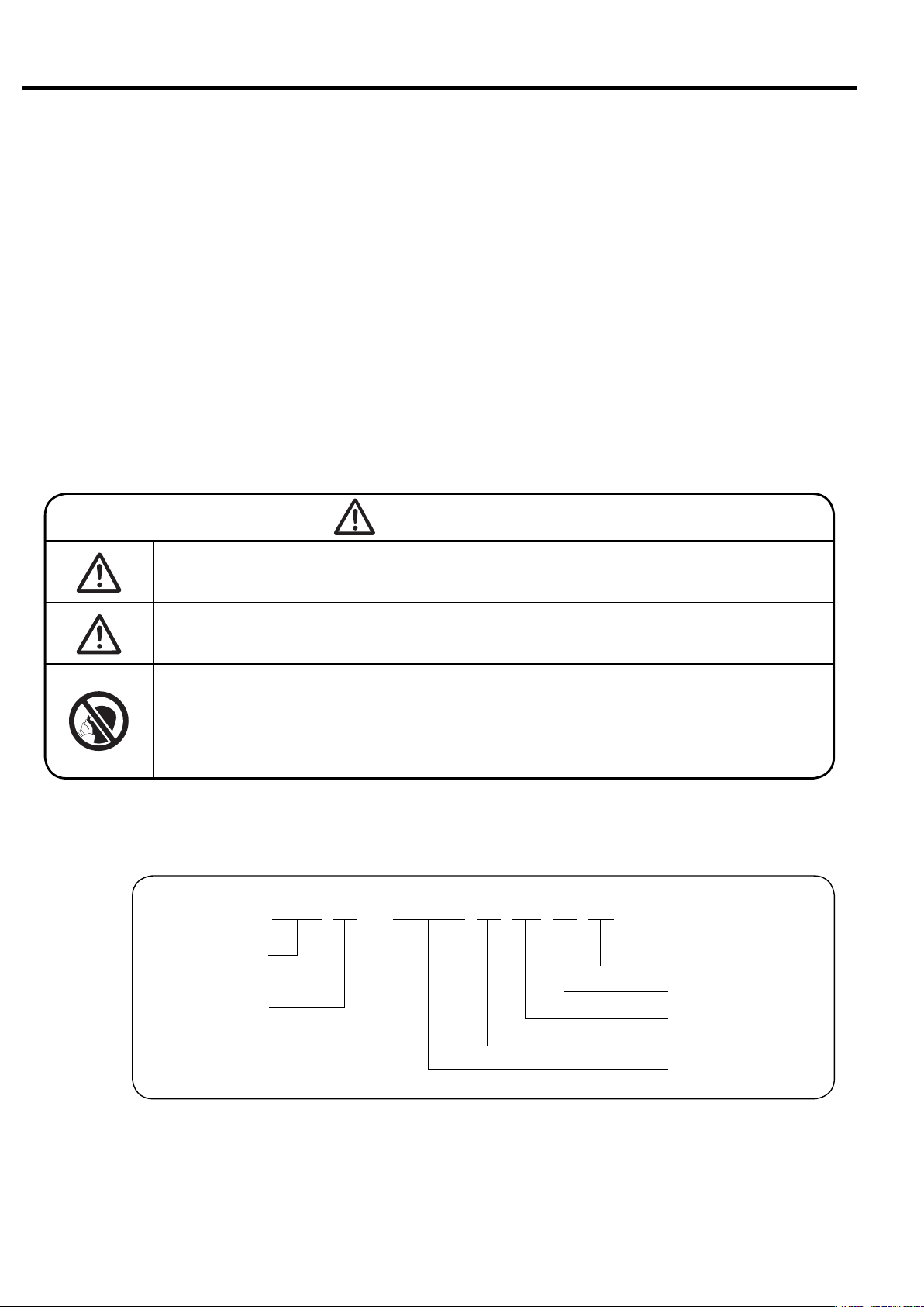
GRAPHIC DESCRIPTIONS:
WARNING
CAUTION
IMPORTANT
:This is a warning. If handled improp-
erly, death or severe injury could
result.
:This is a caution. If handled improp-
erly, injury and/or physical damage
could result.
:This graphic is Variable Speed-control
Drive (VSD) models.
:This graphic is for items that need
attention, other than WARNING and
CAUTION.
:
This graphic is a page number reference.
How to Use This Instruction Manual
● This Instruction Manual covers the standard models of the Hitachi DSP air compressor.
● This Instruction Manual intended to assist daily operators and maintenance personnel
in the installation, operation, control and service of the Hitachi DSP air compressor.
● Prior to operation of this air compressor, ensure that all operators read and understand
this INSTRUCTION MANUAL completely, thereby operating it safely and properly.
Place the INSTRUTION MANUAL near the air compressor to make it available at any
time, and refer to it as the need arises.
● If there are any questions or comments, please contact the local Hitachi distributor or
the nearest Hitachi office.
Fill your DSP’s model name, Serial Number, etc. into the back cover of this Instruction Manual.
●
Such information may be helpful when ordering parts, periodic maintenance, and overhaul.
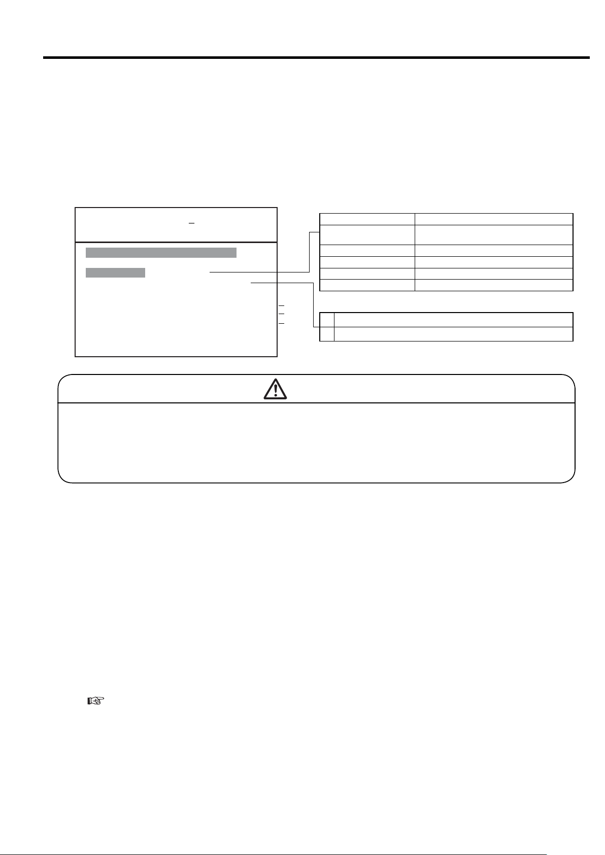
WARNING
Never remove a protective device from the air compressor or modify the air compressor.
It is imperative to install an earth leakage (ground) circuit breaker
on the power cable. This prevents a ground fault accident.
DSP air compressors are not designed, intended or approved for
breathing air applications. Hitachi does not approve specialized
equipment for breathing air applications and assumes no responsibility or liability for compressors used for breathing air services.
■ Model Number Nomenclature
DSP-160VW6N
Dry or Oil-Free Rotary
Screw Air Compressor
Packaged
● Hitachi may make improvements and/or changes in the products described in this publication at any time without notice.
N-Type (NEXT Series)
Frequency (6: 60 Hz)
W: Water-Cooled
w/ V: VSD, w/o V: Fixed
Motor Output (kW)

Contents
1. SAFETY ………………………………………………………………………………………… 2
2.
GENERAL DESCRIPTION
2.2 Components …………………………………………………………………… 5
2.3 Daily Operating Components ………………………………………………… 7
2.1 Appearance
………………………………………………………………………
4
3. OPERATING THE DSP 3.1 Instrument Panel………………………………………………………………… 10
3.2 Start/Stop Operation …………………………………………………………… 12
3.3 How to Use the liquid Crystal Display (LCD)………………………………… 13
3.4 How to Use the Digital Monitor ……………………………………………… 23
3.5 Daily Operation ………………………………………………………………… 30
3.6 Oil Mist Remover Daily Operation…………………………………………… 32
3.7 Adjusting the DSP ……………………………………………………………… 32
4. TROUBLESHOOTING 4.1 Protective Devices ……………………………………………………………… 33
4.2 Troubleshooting the Air Compressor………………………………………… 35
4.3 Troubleshooting the Oil Mist Remover……………………………………… 36
5. INSTALLING 5.1 Unpacking the DSP Air Compressor ………………………………………… 37
AND PIPING THE DSP 5.2 Conveying the DSP Air Compressor ………………………………………… 37
5.3 Installing the DSP Air Compressor ………………………………………… 38
5.4 Piping the DSP Air Compressor ……………………………………………… 39
5.5 Ventilation of Air Compressor Room………………………………………… 43
6. STARTUP OPERATION 6.1 Air Compressor ………………………………………………………………… 44
6.2 Oil Mist Remover ……………………………………………………………… 46
7. WIRING 7.1 Power Supply Transformer and Power Cable ……………………………… 47
7.2 MIV and WIVM wiring ………………………………………………………… 47
7.3 Connecting a Power Cable …………………………………………………… 47
7.4 Wiring Connection Diagram…………………………………………………… 50
7.5 Control Panel /LCD monitor Specifications ………………………………… 50
8.
STANDARD COMPONENTS
AND SUBSYSTEMS
8.3 Cooling Water…………………………………………………………………… 61
8.4 Capacity Control System ……………………………………………………… 62
8.5 Outline of Oil Mist Remover Subsystem …………………………………… 66
9.
MAINTAINING THE DSP
9.2 Standard Maintenance Schedule …………………………………………… 68
9.3 Oil Mist Remover Maintenance ……………………………………………… 72
9.4 How to Service the DSP Air Compressor…………………………………… 73
10.
PRECAUTIONS WHEN THE COMPRESSOR IS TO BE IDLE FOR AN EXTENDED PERIOD OF TIME
8.1 Standard Components ………………………………………………………… 57
8.2 Air/Oil Flow ……………………………………………………………………… 58
9.1 Air Compressor Maintenance………………………………………………… 67
…………… 84
11. PARTS LIST ………………………………………………………………………………………… 85
12. WARRANTY, AFTER-SALES AND SERVICE …………………………………………………………… 103
13. OPERATION RECORD LOGBOOK…………………………………………………………………………… 104
14. STANDARD SPECIFICATIONS ……………………………………………………………………………… 105
1
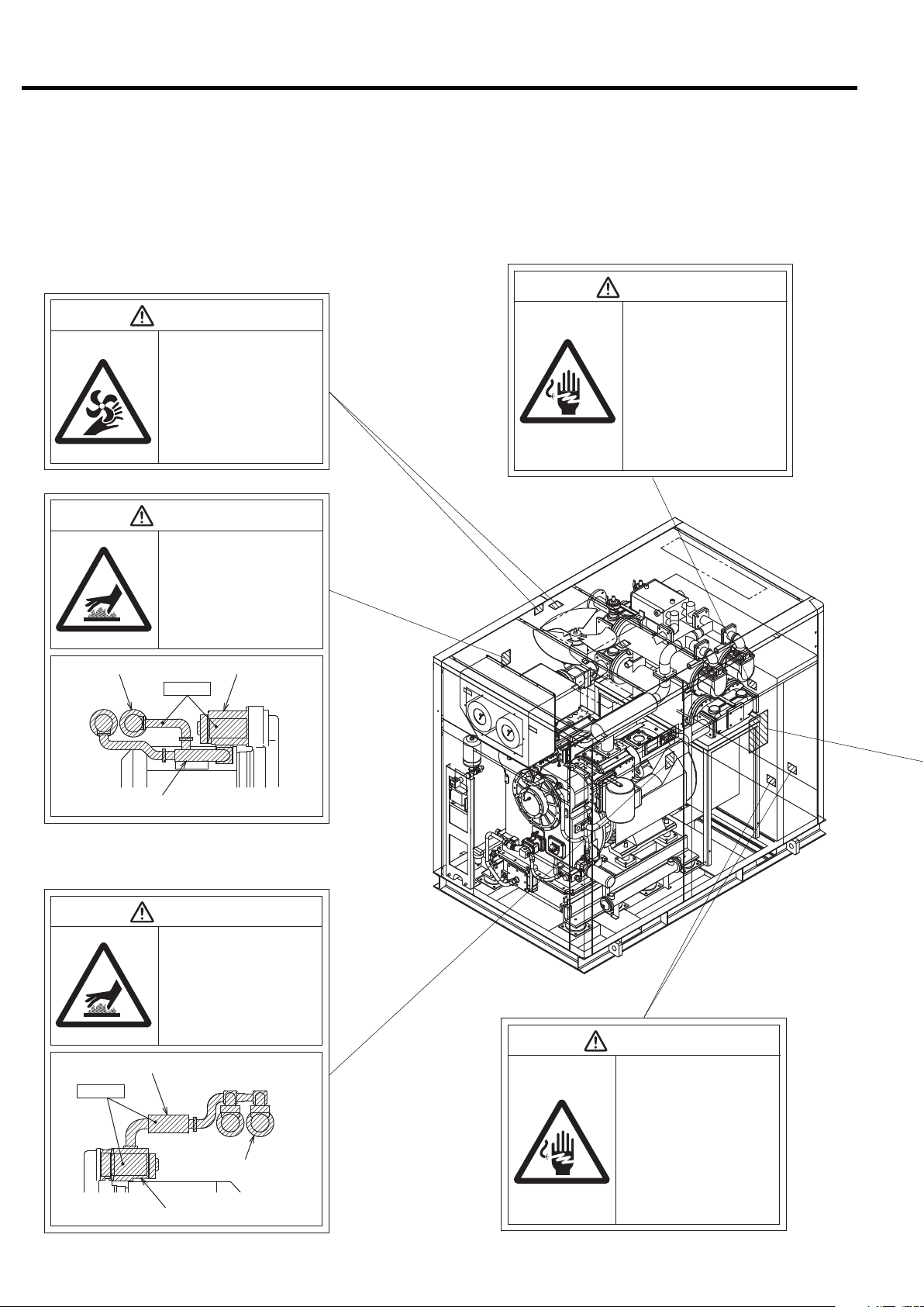
1. SAFETY
To ensure safe and proper operation of the air compressor, it is indispensable to carefully
read and understand the following warnings and instructions detailed below. These warnings and instructions are attached to the air compressor as shown in the figure below.
WARNING
WARNING
Rotating Parts!
●Keep hands and rods, etc. away from
the rotating parts (Cooling fans, etc.)
●Use caution at all times, when air com-
pressor is powered. The air compressor may be capable of restarting without hitting the START button.
●When the air compressor is operating,
do not remove or open the enclosure
panels and doors.
●Before servicing the air compressor,
stop it, disconnect the power, especially
when accessing any rotating parts.
WARNING
Hot Surface!
●Do not directly touch any component
inside the air compressor enclosure
when the air compressor is operating
or immediately after it has stopped,
as the components are extremely hot
and can cause severe injury.
●Before servicing the air compressor,
stop it, disconnect the power, then
wait for the air compressor to cool
down.
Electric Shock Hazard!
●Before servicing or wiring the
air compressor, disconnect
the power. This will prevent
anyone from turning on the
power and causing an electric shock that could lead to
severe injury or death.
●Do not allow any unlicensed
person to wire the air compressor. Always use a licensed
electrician.
●Ground the air compressor.
Intercooler Header
Discharge Air pipe
Discharge Air pipe
Heated!!
Air End
Heated!!
WARNING
Hot Surface!
●Do not directly touch any component
inside the air compressor enclosure
when the air compressor is operating
or immediately after it has stopped,
as the components are extremely hot
and can cause severe injury.
●Before servicing the air compressor,
stop it, disconnect the power, then
wait for the air compressor to cool
down.
Aftercooler Header
Air End
WARNING
Electric Shock Hazard!
●Before servicing or wiring the
air compressor, disconnect
the power. This will prevent
anyone from turning on the
power and causing an electric shock that could lead to
severe injury or death.
●Do not allow any unlicensed
person to wire the air compressor. Always use a licensed
electrician.
●Ground the air compressor.
2
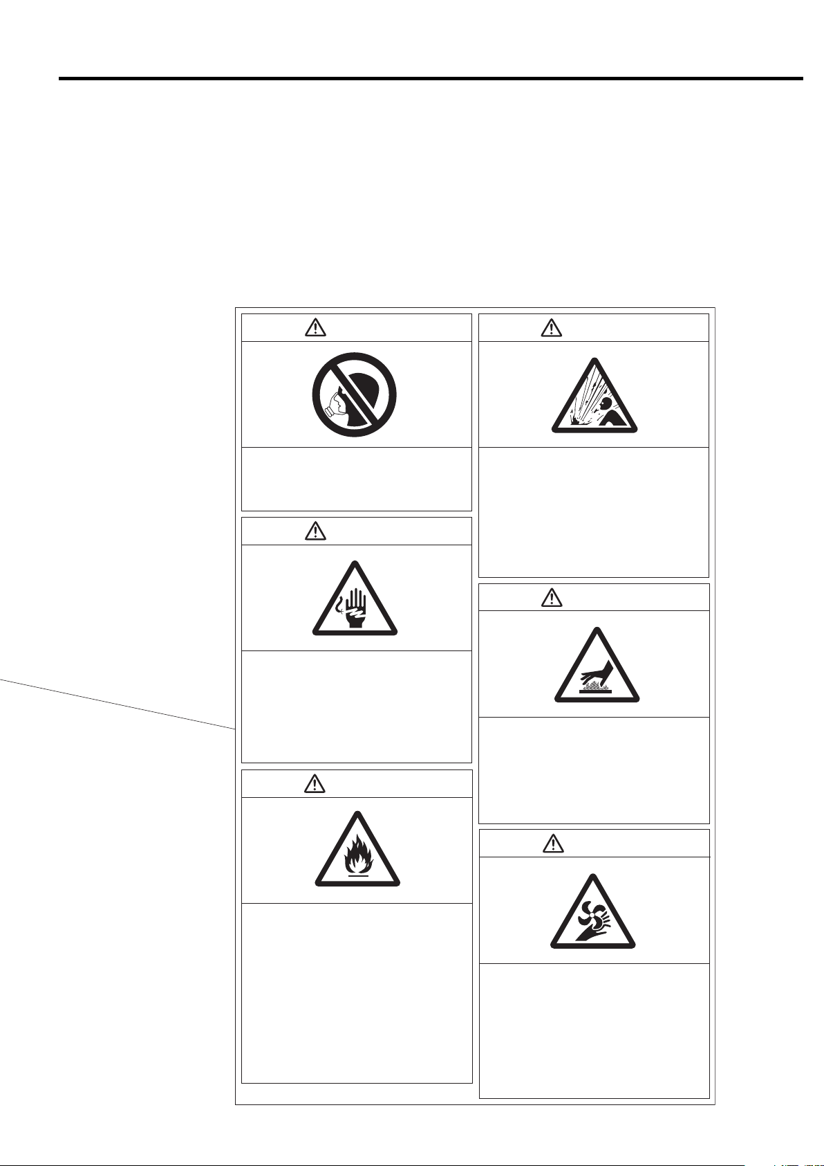
WARNING WARNING
1. SAFETY
Do Not Breathe Air!
Discharge air can contain Carbon Monoxide and
other contaminants. Breathing the air can cause
severe injury or death.
WARNING
Electric Shock Hazard!
●
Before servicing or wiring the air compressor,
disconnect the power. This will prevent anyone
from turning on the power and causing an electric
shock that could lead to severe injury or death.
●
Do not allow any unlicensed person to wire the air
compressor. Always use a licensed electrician.
●Ground the air compressor.
CAUTION
●
High pressure air can cause severe injury or death.
Be careful when air compressor is operating.
Pressurized air can blow out of safety relief valves
and etc. at incredibly high velocities.
●When using compressed air to clean equipment,
use extreme caution and/or wear eye protection.
●Before servicing the air compressor, stop it,
disconnect the power, and relieve pressure before
removing filter, plug, fitting or cover.
WARNING
High Pressure Air!
Hot Surface!
●Do not directly touch the air end, discharge air
pipe,and coolers when the air compressor is
operating and immediately after it has stopped,
because these parts are heated then.
Before servicing the air compressor (especially
●
when accessing to the heated parts), stop it, disconnect the power, and wait until it is cooled down.
WARNING
●
Preoaution against Fire!
Keep any other hazardous materials such as
flammable solvents away from the air compressor.
Also do not use fire nearby it; otherwise a spark
may enter the air compressor and burn it internally.
●Do not remove any protective relayʼ s. Also do
not make a modification of the control circuit that
may result in impairing the protective relayʼ s
function. Remember that the loss of the protective
relayʼ s function may cause serious damage.
●Install an earth leakage circuit breaker between
the air compressor and the power supply. Do not
use a disconnector such as a knife switch
because it cannot protect the air compressor and
may cause burnout of the air end if a ground fault
has occurred.
Rotating Parts!
●Keep hands and rods, etc. away from the rotating
parts (Cooling fans, etc.)
●Use caution at all times, when air compressor is
powered. The air compressor may be capable of
restarting without hitting the START button.
●When the air compressor is operating, do not
remove or open the enclosure panels and doors.
●Before servicing the air compressor, stop it, dis-
connect the power, especially when accessing
any rotating parts.
3
2. GENERAL DESCRIPTION
This section illustrates and describes the major components of the DSP air compressor. Be familiar
with the name, location and function of each component before using the DSP air compressor.
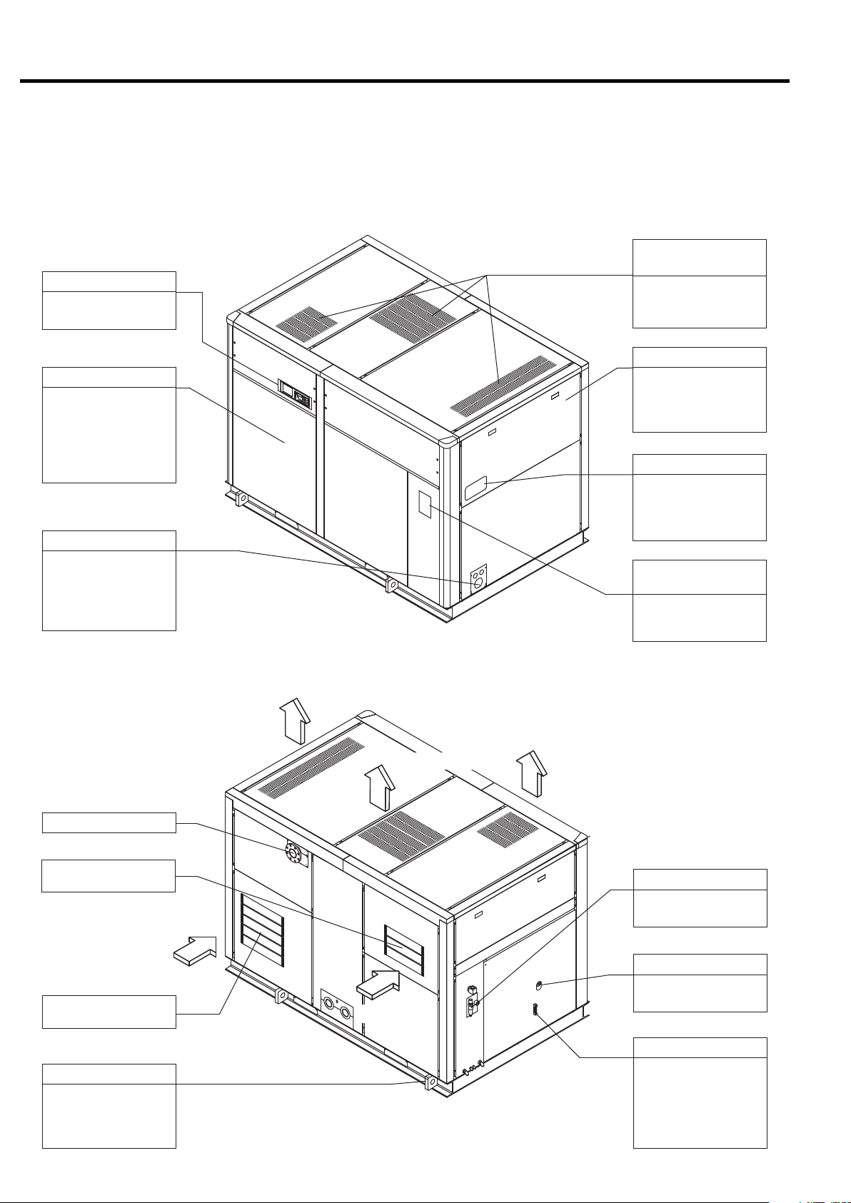
2.1 Appearance
2.1.1 Fixed Speed
[Front View]
Air Exhaust
(Air Compressor Package)
Instrument Panel
See page p. 10, chapter 3, for details.
Front Left Door
Open the front left
door only when servicing the DSP air compressor. Keep it closed
when operating the
DSP air compressor.
Power Supply Port
Check the specifications, power supply
and voltage before
connecting the power
supply.
This panel discharges
the hot air generated
in the air compressor.
Enclosure
Enclosure panels
lower the sound level
of the air compressor
package.
Compressor Name plate
Model designation,
manufacturing number
and specification are
printed.
Plate of Operating /
Servicing Instructions
Read carefully the
plate before operating
and servicing the DSP.
[Rear View]
Compressed Air Discharge
Air Intake
(Inlet to the Air End)
Air Intake
Air Intake
(Air Compressor Package)
Sling Fitting
Use the sling fitting
when moving and
installing the DSP air
compressor.
Air Exhaust
Air Exhaust
Air Exhaust
OMR
See page 55 for the
details
Oil Filling Port
Use the port to fill the
gear case with oil.
Air Intake
Oil Level Gauge
This indicates the
quantity of the oil in
the gear case. Check
the oil level before
starting the DSP and
when operating it.
4
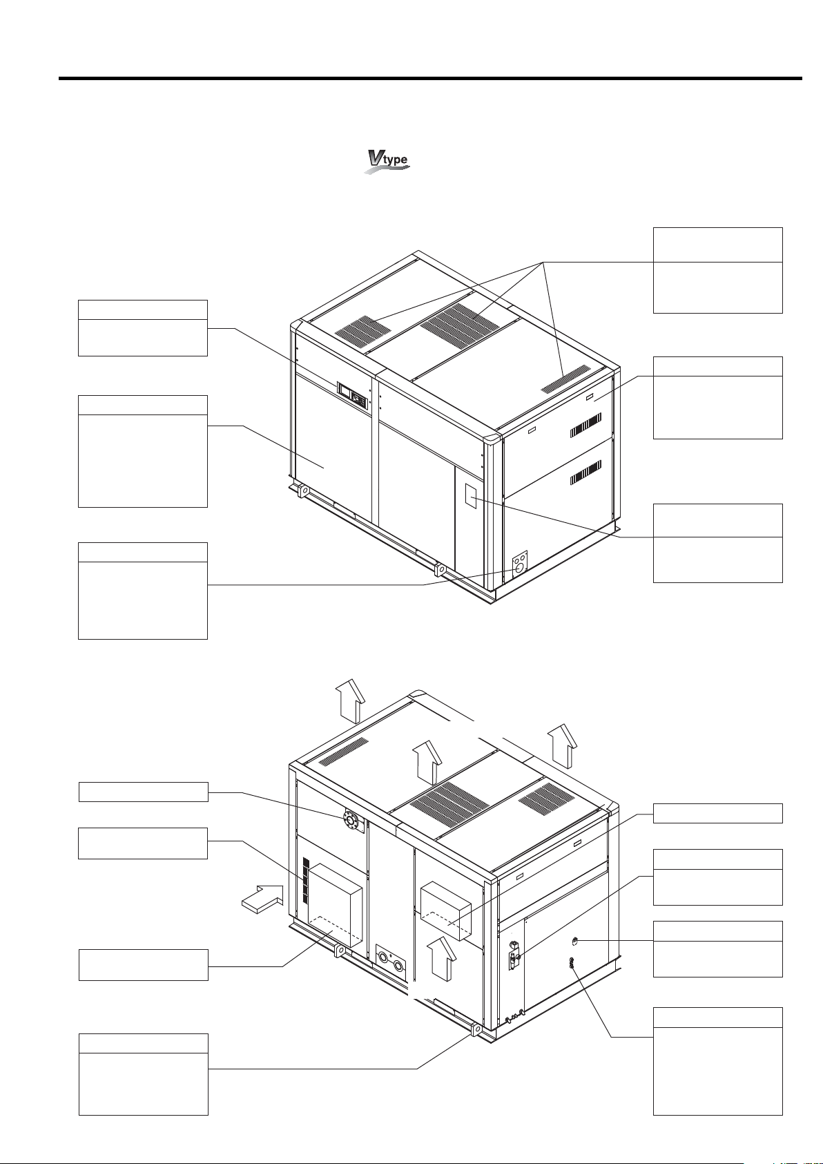
2.1.2 Variable Speed Drive Control
[Front View]
Instrument Panel
See page p. 10, chapter 3, for details.
Front Left Door
Open the front left
door only when servicing the DSP air compressor. Keep it closed
when operating the
DSP air compressor.
Power Supply Port
Check the specifications, power supply
and voltage before
connecting the power
supply.
2. GENERAL DESCRIPTION [Appearance]
Air Exhaust
(Air Compressor Package)
This panel discharges
the hot air generated
in the air compressor.
Enclosure
Enclosure panels
lower the sound level
of the air compressor
package.
Plate of Operating /
Servicing Instructions
Read carefully the
plate before operating
and servicing the DSP.
[Rear View]
Compressed Air Discharge
Air Intake
(Inlet to the Inverter)
Air Intake
Air Intake
(Air Compressor Package)
Sling Fitting
Use the sling fitting
when moving and
installing the DSP air
compressor.
Air Exhaust
Air Exhaust
Air Exhaust
Compressed Air Discharge
OMR
See page 66 for the
details
Oil Filling Port
Use the port to fill the
gear case with oil.
Air Intake
Oil Level Gauge
This indicates the
quantity of the oil in
the gear case. Check
the oil level before
starting the DSP and
when operating it.
5
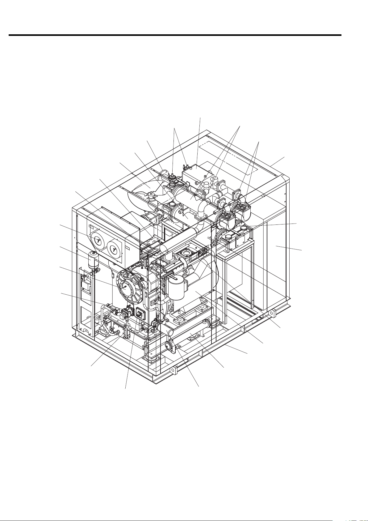
2. GENERAL DESCRIPTION [Components]
2.2 Components
Discharge Pipe
(Compressed Air Discharge)
Blow-off air cooler
Safety Relief Valve
Aftercooler
Check Valve
2nd-Stage Air end
Air Intake Filter
Oil Mist Remover
Gear Case
Oil Pump
Ventilating Fan
1st-Stage Air end
Intercooler
Enclosure
Intercooler
Starter /
Control Box
Instrument Panel
Main Motor
Common Base
Oil Level Gauge
Oil Filling Port
Oil Filter
Oil Cooler
6
2. GENERAL DESCRIPTION [Daily Operating Components]
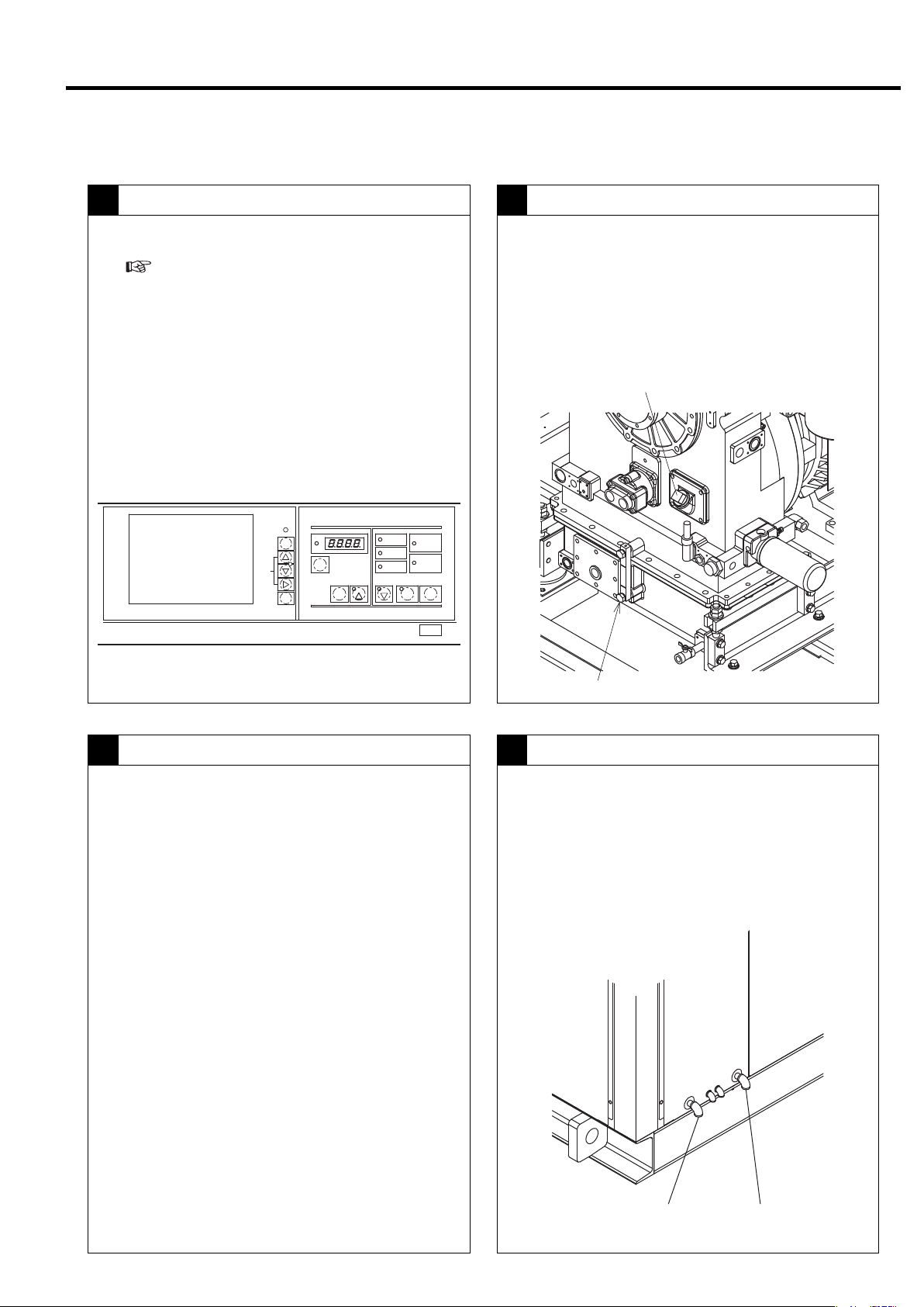
2.3 Daily Operating Components
Controls on the Instrument Panel
1 2
● Indicates the operation control section.
(
For more information, see Chapter 3, on
page 10.)
● Operation ON → POWER light on.
● Start: Press START button → Operation Light on
during operation
● Stop: Press UNLOAD STOP button →
unloading
stops for 5 minutes → Operation Light off during
operation
● Power OFF: → POWER light off
MONITOR
自動
AUTO
モニタ
MONITOR
メニュー
MENU
+/−
UP/
DOWN
設定
SET
運転管理
RUNNINGCONTROL
警報
ALARM
機能
FUNC
リセット
RESET
遠方
記憶
STR
[×10h]
表示切替/
ワイド モード
SELECT/WIDE
1
運転状況
RUNNINGMODE
遠方
REMOTE
負荷
LOAD
故障
SHUTDOWN
2
電源
POWER
起動待ち
AUTOSTART
運転 停止
STOP
STARTREMOTE
UNLOAD STOP
Oil Level Gauge
● Verify that the oil level of the lubricating oil is
between the red lines during operation.
Lubricating oil circulates in the cooler and piping during
operation, so the position of the oil level differs when the
compressor is running and when it is off. The level rises
when the compressor stops running.
Oil Filling Port
Lubricating Oil
3 4
Oil: Use genuine Hitachi GL-68 DSP Compressor Oil.
Replace the oil every 8,000h operating hour or
every 2-year, whichever comes earlier.
Oil Level Gauge
Aftercooler and Intercooler - Condensate Drain Valve
● Verify that air containing drainage is discharged
intermittently from the intercooler and after cooler
drain ports.
The higher the temperature and humidity, the more drainage
is produced. Drainage may not be produced on the intercool-
er side during winter.
After cooler
drain port
Intercooler
drain port
7
2. GENERAL DESCRIPTION [Daily Operating Components]
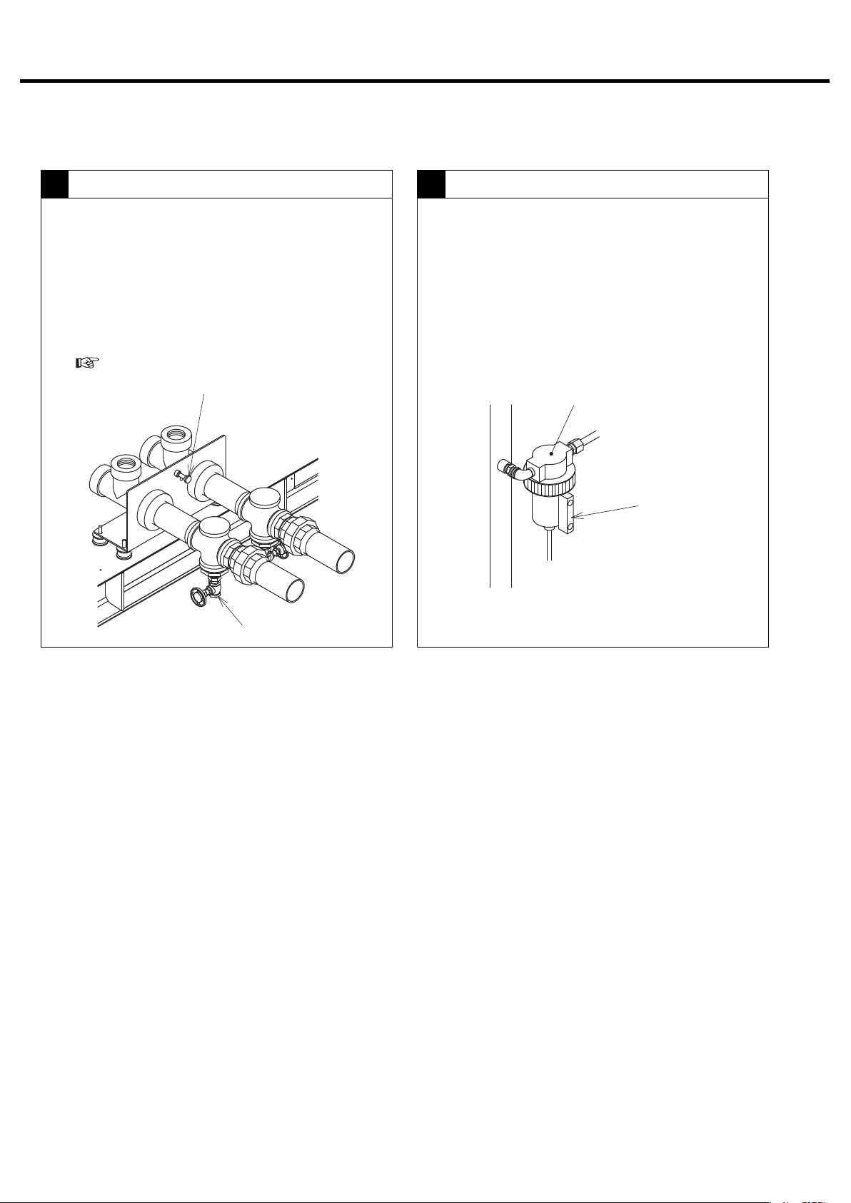
Cooling Water
5
① Shut off the cooling water when the compressor is
off.
② Open the peacock for draining water. Also open
the valve of the water drain port and drain the
cooling water.
③ Be especially careful of freezing during the winter.
(
For details, see page 61.)
Water drain peacock
Control Line Filter (Fixed Speed)
6
● Check the condensate drain discharge from the
control line filter by checking the sight glass on the
control line filter.
Control Line Filter
Sight Glass
Water drain port
8
2. GENERAL DESCRIPTION [Daily Operating Components]
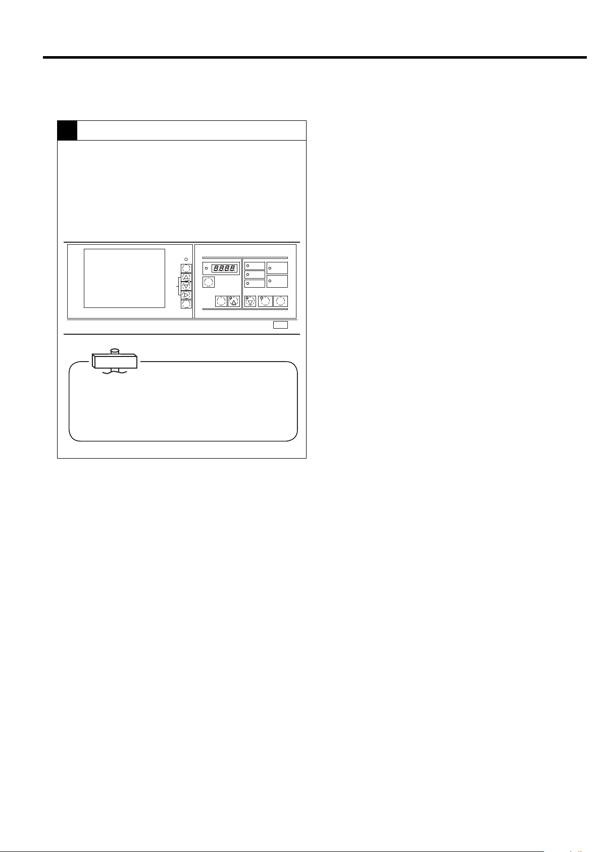
Stopping operation
7
●Normally use UNLOAD STOP button to stop the
compressor. The compressor then unloads for 5
minutes and stops running.
(In the case of an emergency, press the STOP
button to stop operation.)
MONITOR
自動
AUTO
モニタ
MONITOR
メニュー
MENU
+/−
UP/
DOWN
設定
SET
運転管理
RUNNINGCONTROL
警報
ALARM
機能
FUNC
リセット
RESET
遠方
記憶
STR
[×10h]
表示切替/
ワイド モード
SELECT/WIDE
1
運転状況
RUNNINGMODE
遠方
REMOTE
負荷
LOAD
故障
SHUTDOWN
2
電源
POWER
起動待ち
AUTOSTART
運転 停止
STOP
STARTREMOTE
UNLOAD STOP
IMPORTANT
Keeping the second-stage air end as dry as possible is
essential for preventing it from rusting due to a longterm operation suspension. When stopping the DSP,
therefore, execute an unloading operation and thereby
remove the moisture from the second-stage air end.
9
3. OPERATING THE DSP
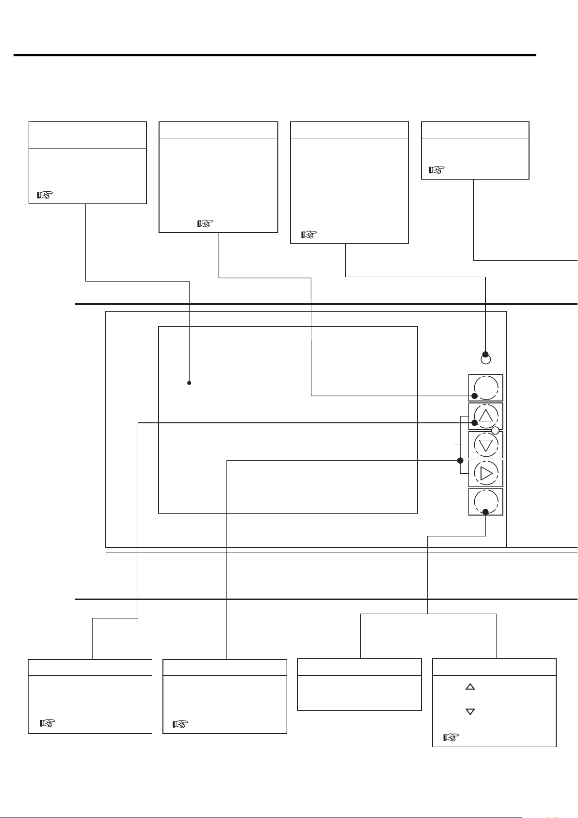
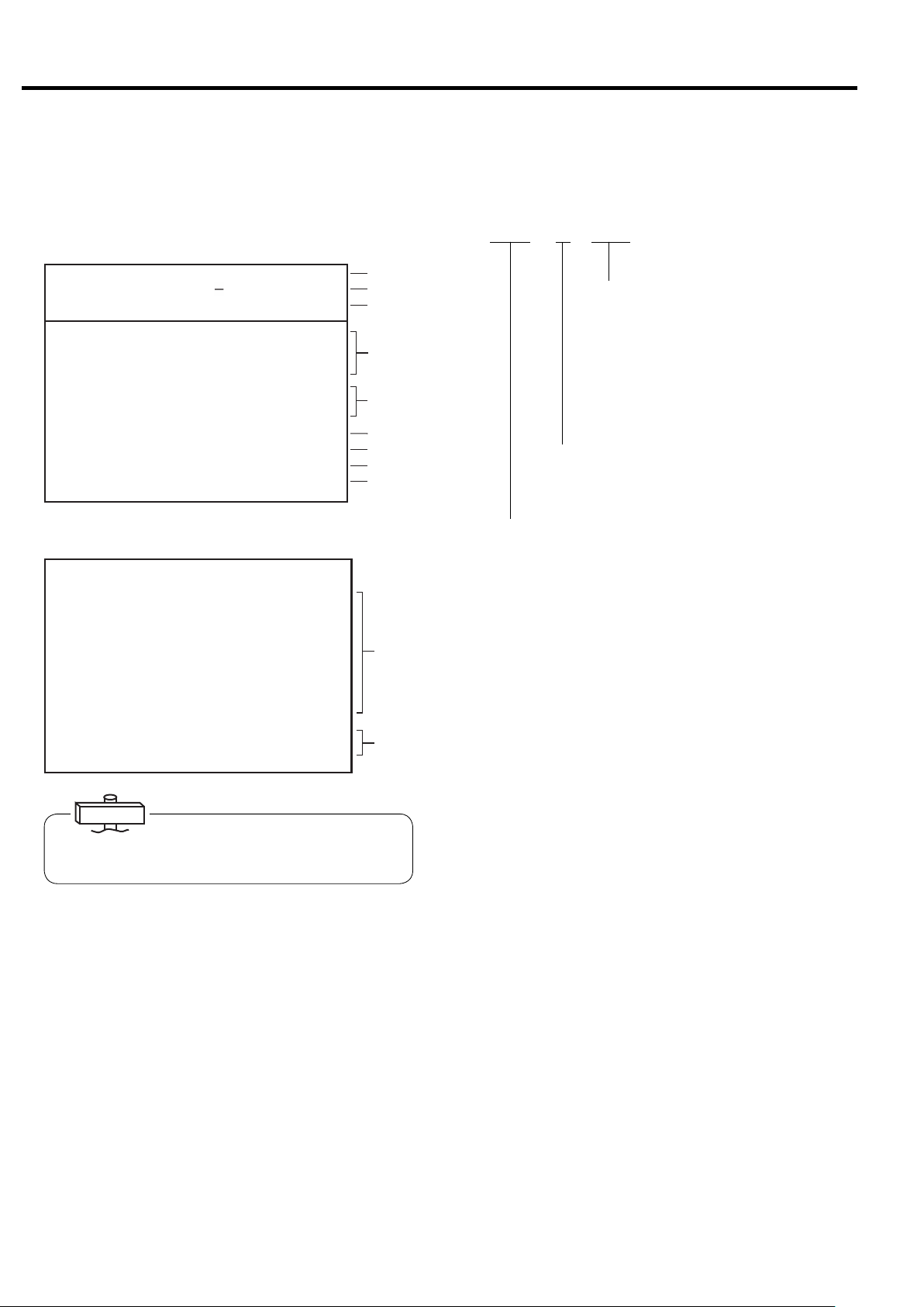
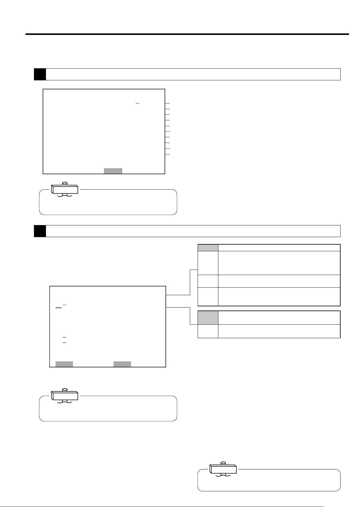
3.1 Instrument Panel
Liquid Crystal Display
(LCD)
Displays the operation data,
various setting, shutdowns/
alarms information, etc
( page 13)
MONITOR Button
Enables movement within
each of the monitoring
displays (M1, M2) and the
message display (M3). This
button also enables you to
return to the M1 display from
the FUNCTION MENU
display ( page 13).
AUTO light (yellow)
ON (glowing) when an
automatic operation (an
AUTO operation, a scheduling operation, or lead/lag
operation) is activated.
ON (flashing) when external
calendar or scheduling
operation is abnormal.
( page 16, 20)
RESET Button
Reset the system or cancels
the shutdown/alarm circuit
( page 15)
自動
AUTO
モニタ
MONITOR
メニュー
MENU
MENU Button
Functions to display the
menu screen and move the
cursor.
( page 18)
MONITOR
+/- UP DOWN Buttons
Each of these buttons act as
an up-arrow, down-arrow
and right-arrow key.
( page 18)
SET Button
It saves any adjusted set
points.
+/−
UP/
DOWN
設定
SET
Contrast adjustment
SET+[ ] button operation:
Brightens the display.
SET+[ ] button operation:
Darkens the display.
( page 22)
10
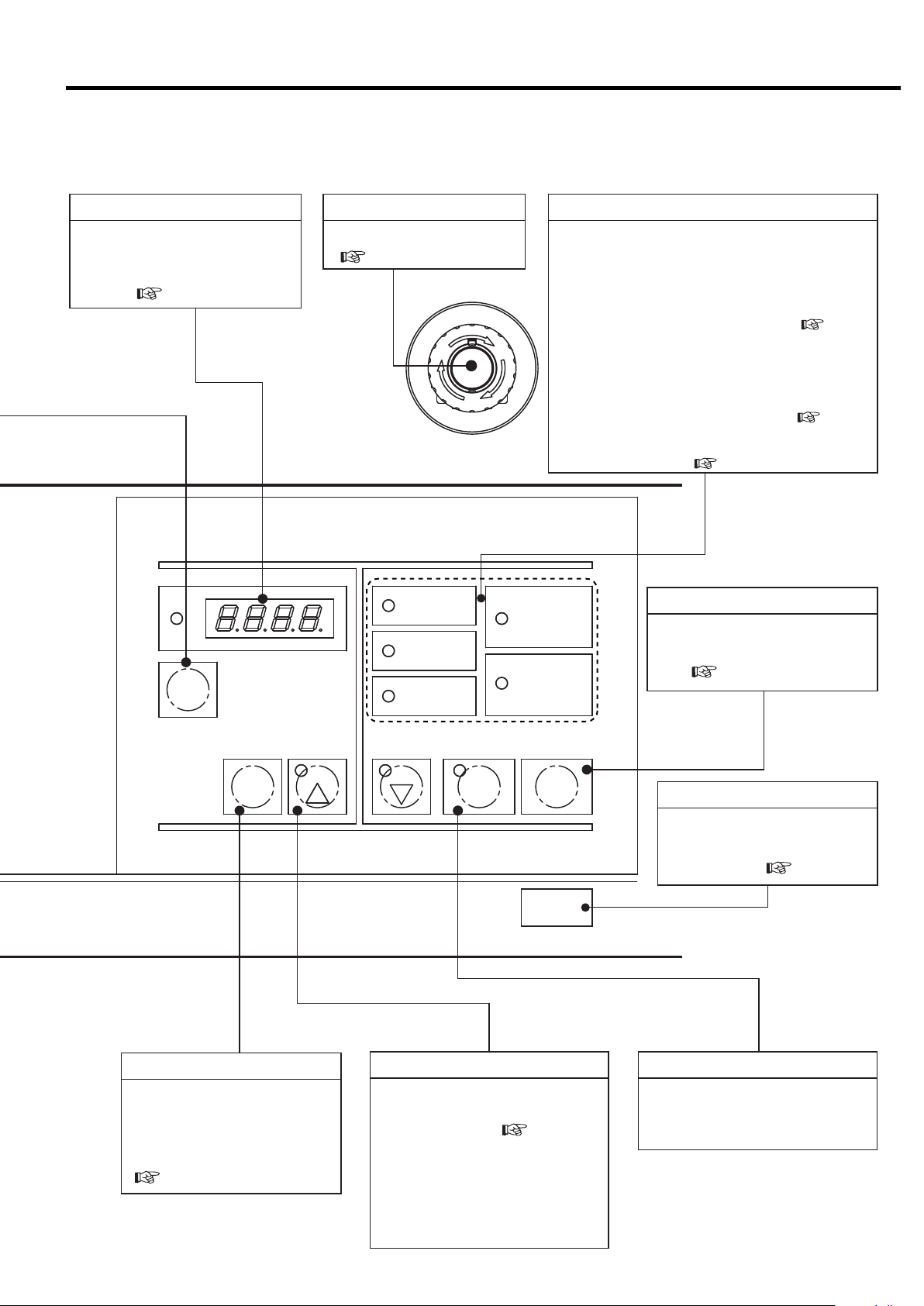
3. OPERATING THE DSP [Instrument Panel]
Digital Monitor
In addition to basic settings, used
to set various types of setting
values in combination with the LCD
monitor. ( page 22)
運転管理
RUNNINGCONTROL
警報
ALARM
機能
FUNC
リセット
RESET
遠方
記憶
STR
ワ イド モ ード
EMERGENCY STOP button
Stops for emergency.
( page 12)
遠方
REMOTE
負荷
[× 10h]
LOAD
故障
SHUTDOWN
表示切替/
SELECT/WIDE
1
2
G
E
R
N
E
M
E
S
C
Y
P
T
O
運転状況
RUNNINGMODE
電源
POWER
起動待ち
AUTOSTART
運転 停止
STARTREMOTE
RUNNING MODE Light
POWER light (yellow):
ON (glowing) when the power to the air compressor is turned on.
REMOTE light (green):
ON (glowing) when the REMOTE button is pressed in
order to activate a remote operation.
ON (flashing) when an external remote-operation-activation switch has
been turned on in order to activate a remote operation.
LOAD light (yellow):ON (glowing) when the air compressor is loading.
AUTO START light (green):
ON (glowing) while the air compressor is in a stop due to an
AUTO operation, lead/lag operation, or scheduling operation.
ON (blinking) while the air compressor is in a stop due to a
restartable instantaneous power interruption. ( page 16)
SHUTDOWN light (red):
ON (either glowing or blinking) when a shutdown/alarm
problem has occurred. ( page 15)
( page 28)
STOP Button
Used to stop the compressor
immediately without first unloading. ( page 12)
STOP
UNLOAD STOP Button
Press this button to stop the air compressor.
The air compressor will stop after removing the
condensate from the air end.
※This stop button is effective while a stand alone operation.
REMOTE Button
Activates or deactivates a remote
start/stop operation locally or on
the instrument panel. it also acts
as a right-arrow key stop
( page 28).
UNLOAD STOP
SELECT/WIDE Button/Light (Yellow)
Press to confirm various types of
setting values, shutdown history,
and setting status. (
To set to ECONOMODE (energy
conservation mode) (standard type
only), press and hold the SELECT/
WIDE button for at least 7 seconds.
The light flashes and ECONOMODE
is set.
page 24, 25
)
Used for normal stop. Stops
after the compressor and air
hoses are dry. ( page 12)
START Button
Starts the air compressor.
The OPERATION light (red) turns
on while the compressor is running.
11
3. OPERATING THE DSP [Start/Stop Operation]
3.2 Start/Stop Operation
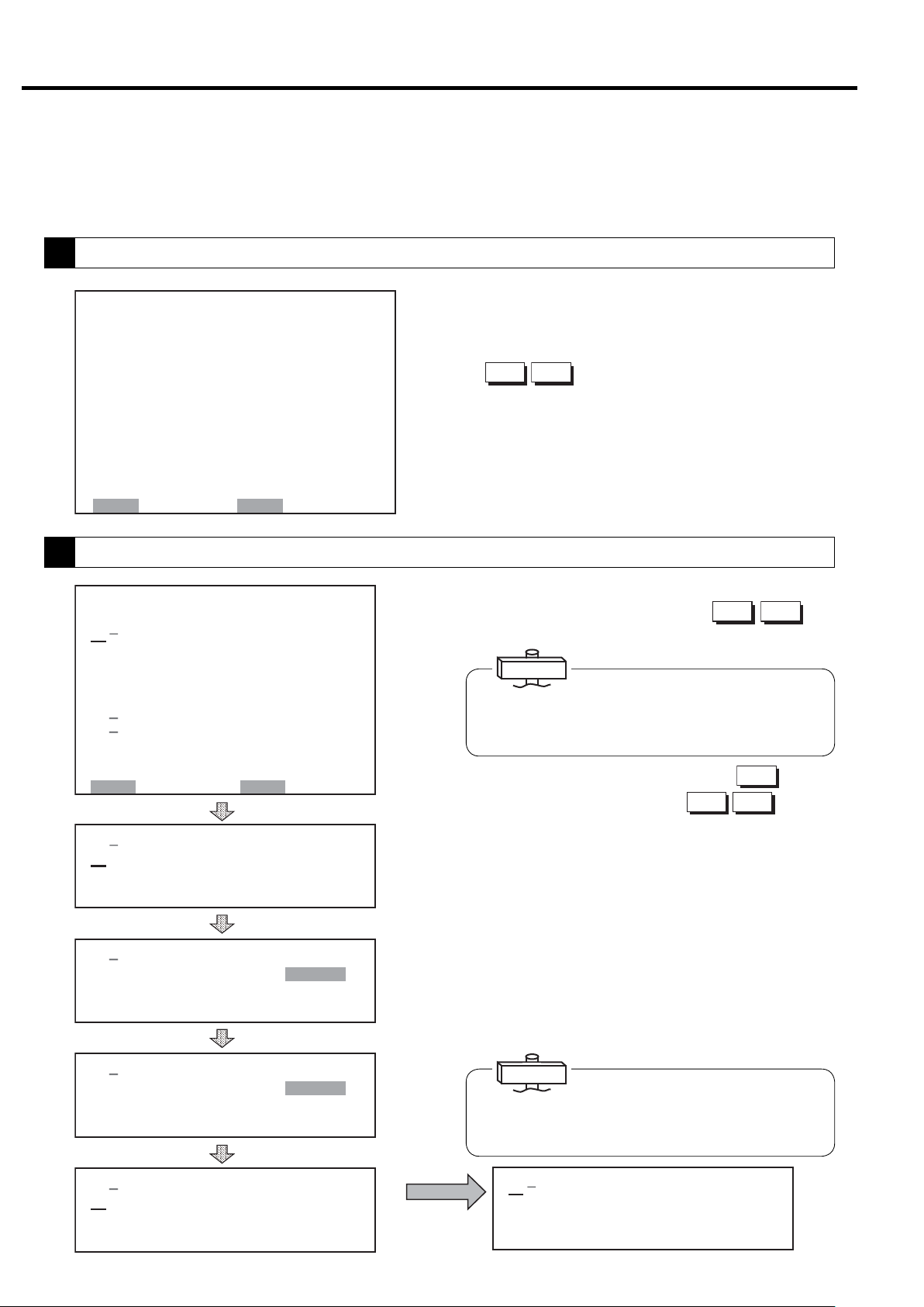
3.2.1 Connecting the Power
When you connect the power, the POWER light turns on
and the LCD monitor displays the following screen for 5
seconds, and then switches to the monitor screen (M1)
that displays control settings, discharge air pressure, and
total operating hours.
COMPRESSOR MONITOR
CONTROLLER
5 sec
㻞㻜㻜㻥䠋㻜㻠䠋㻝㻟 㻝㻥䠖㻜㻞
㼀㼅㻼㻱䠖㼂㻿㻰㻭
㻰 㻵 㻿䠊㻼㻾㻱㻿㻿 䠖 㻜䠊㻜 㻜㼜 㼟 㼕
㻾㼁㻺 㻌㻴㻻㼁㻾 䠖 㻝 㻞 㻜 䡄
㻸㻻㻭㻰 㻌 㻴㻻㼁㻾 䠖 㻡 㻠䡄
㻸㻻㻭㻰 㼀 㻵 㻹㻱㻿 䠖 㻝㻞 㻟
㻸㻻㻭㻰 㻾㻭㼀㻱䠖 㻝 㻝䠂
㻸㻻㻭㻰 㼀 㻵 㻹㻱 䠖 㻞 㻠䡏
㼁㻺㻸㻻㻭㻰 㻌 㼀 㻵㻹㻱 䠖 㻝䡏
㻯㼁㻾㻾㻱㻺㼀 䠖 㻡 㻜䠝
㻲㻾 㻱㻽㼁㻱 㻺㻯㼅䠖 㻞 㻟 㻚 㻤䠤䡖
㻻㼁㼀㻼㼁㼀䠖 㻝 㻜 㻚 㻡䡇䠳
3.2.2 Start/Stop
When the START button is pressed the START light
turns on and the compressor starts operating. When running, the asterisk on the right side of running hours
flashes and running time is counted.
To stop, press the UNLOAD STOP button. Operation
stops when the air end and the air piping have dried for 5
minutes.
To stop the compressor immediately without unloading,
press the STOP button.
Note: If the STOP button is pressed while unloading, the
compressor stops immediately.
3.2.3 Emergency Stop
Pressing EMERGENCY STOP botton, the DSP compressor immediately.
This switch should only be pressed in emergency.
The compressor can not be restarted until the switch is
manually reset. Turn the switch knob clockwise and
press the RESET button to reset.
*The asterisk flashes when the clock and total run-
ning hours are engaged.
If phase is reversed, “Connection Error: Reverse
Phase” is displayed on the LCD monitor for setting and
connection inspection. In this case, switch 2 of the 3
main power cables.
If there is no phase, “Connection Error: No Phase” is
displayed on the LCD monitor. In this case, check the
power cables.
12
3. OPERATING THE DSP [How to Use the Liquid Crystal Display (LCD)]
3.3 How to Use the liquid Crystal Display (LCD)
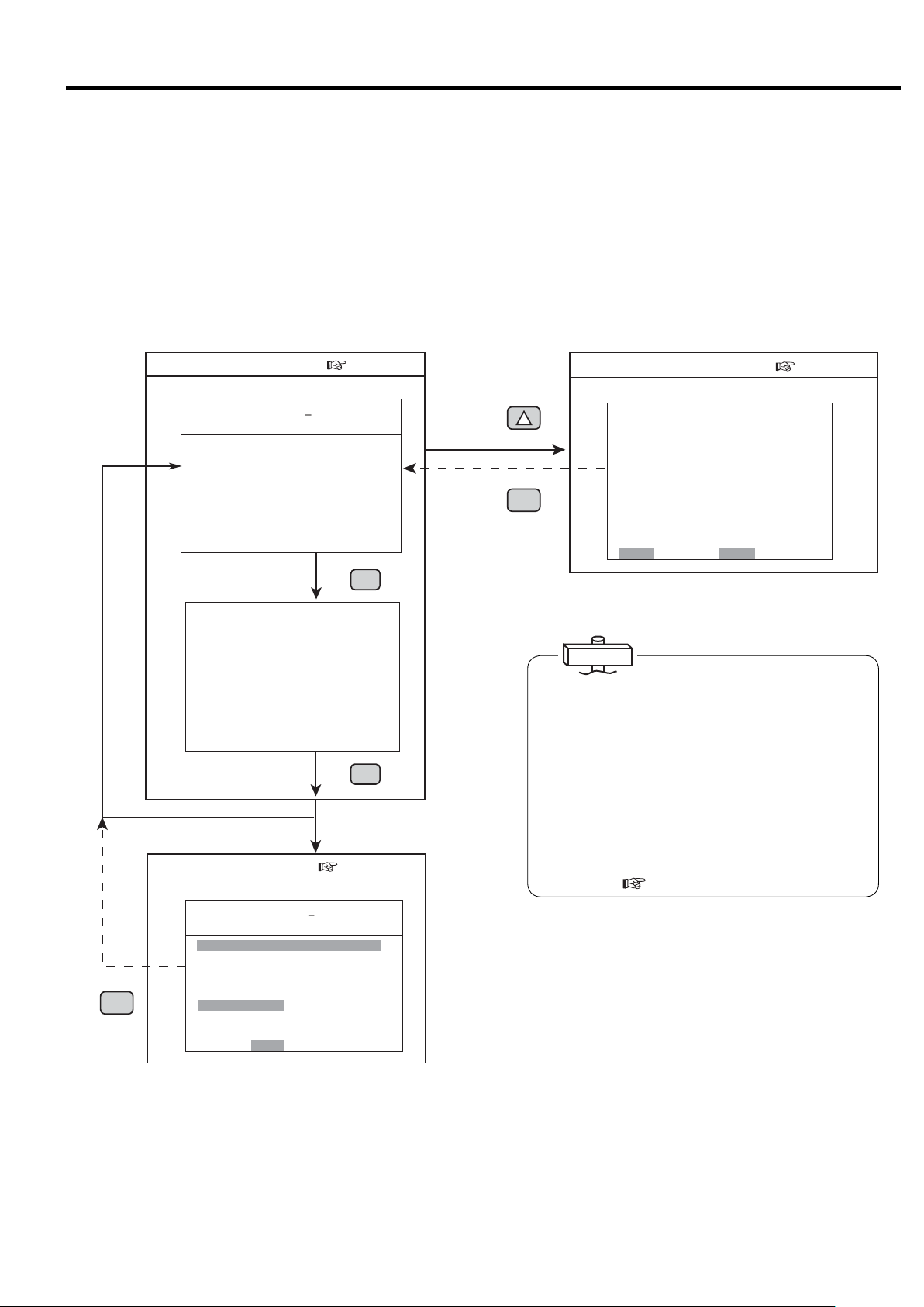
3.3.1 How to Move between the Various Displays
■Monitoring Displays
There are three monitoring displays: M1, M2, and
M3. To move between these displays, press the
MONITOR button.
■Monitoring Display(p.12)
M1 Monitoring Display
㻞㻜㻜㻥䠋㻜㻠䠋㻝㻟 㻝㻥䠖㻜㻞
㼀㼅㻼㻱 䠖㼂㻿㻰㻭
㻰 㻵 㻿䠊㻼㻾 㻱㻿㻿 䠖 㻜䠊 㻜 㻜 㼜 㼟 㼕
㻾㼁㻺 㻌㻴㻻㼁㻾 䠖 㻝 㻞㻜 䡄
㻸㻻㻭㻰 㻌 㻴㻻㼁㻾 䠖 㻡 㻠 䡄
㻸㻻㻭㻰 㼀 㻵 㻹㻱㻿 䠖 㻝 㻞 㻟
㻸㻻㻭㻰 㻾㻭㼀㻱 䠖 㻝㻝䠂
㻸㻻㻭㻰 㼀 㻵 㻹㻱 䠖 㻞㻠 䡏
㼁㻺㻸㻻㻭㻰 㻌 㼀 㻵 㻹㻱䠖 㻝䡏
㻯㼁㻾㻾㻱㻺㼀 䠖 㻡 㻜䠝
㻲㻾㻱 㻽㼁㻱㻺㻯 㼅䠖 㻞 㻟 㻚 㻤䠤䡖
㻻㼁㼀㻼㼁㼀䠖 㻝㻜 㻚 㻡 䡇䠳
モニタ
モニタ
MONITOR
M2 Monitoring Display
㻞㻜㻜㻥䠋㻜㻠䠋㻝㻟 㻝㻥䠖㻜㻞
㻼㻾㻱㻿㻿㼁㻾㻱
㻵 㻺㼀 㻿 㼀㻳 䠊 㻼 䠖 䚷䚷 㻞 㻥 㼜 㼟 㼕
㻻 㻵 㻸 㻌 㻼㻾㻱㻿 䠖 㻌 㻌 㻝㻡 㼜 㼟 㼕
㻯㻸㼀䠊㻼 㻾㻱㻿 䠖 㻖䠊㻖 㻖 㼜 㼟 㼕
㼀㻱㻹㻼㻱㻾㻭㼀㼁㻾㻱
㻰㻵㻿䠊㼀㻱㻹㻼㻝䠖 㻟㻞㻜䉣
㻰 㻵 㻿䠊㼀㻱㻹㻼 㻞 䠖 㻟㻝㻟㻤䉣
㻻 㻵 㻸 㻌 㼀 㻱㻹㻼 䠖 㻟 㻣 䉣
㻯㻸㼀䠊㼀㻱㻹㻼䠖 㻖㻖㻖䉣
㻞㻺㻰 㻌 㻿㼁㻯㼀䠊㼀䠊 䠖 㻜 㻤䉣
㻹㻭 㻵 㻺㼀㻱㻺 㻭㻺㻯㻱
㻴㻾䠊㼀㻻㻌㻹㻭㻵㻺㼀䠖 㻜㻜㻜㻜䡄
㻺㻱㼄㼀㻌㻹㻭 㻵㻺㼀䠖 㻖㻖㻖㻖
■Message Display(p.13)
M3 Monitoring Display
㻞㻜㻜㻣䠋㻜㻤䠋㻜㻝 㻝㻥䠖㻝㻥 㻖
㼀㼅㻼㻱 䠖㼂㻿㻰㻭
㻰 㻵 㻿䠊㻼㻾 㻱㻿㻿 䠖 㻜䠊 㻠 㻢
䠘㻿 㻴 㼁 㼀 㻰 㻻 㼃 㻺䠚
㻯㻻㻻㻸㻭㻺㼀䠖
㻻㻵 㻸䠖
㻞䠪㻰 㻌 㻿 㼁㻯 㼀䠊 㼀 㻱
㻴㻵㻳㻴 㻌㻰㻵㻿䠊㼀㻱㼜㼟㼕
㻯 㻻 㻺 㼀 㻭 㻯 㼀 㻻 㻾 㻌㻱 㻾 㻾 䠖
㻻㼂㻱㻾 㻸㻻㻭㻰 䠖
㻸㻻㼃 㻌㼃 䠊 㻵 㻺 㼀 㻿 㼀㻳 㻌 㻼䠊
㻰 㻾 㼅 㻱 㻾 㻌㻌㻌㻌 㼃 䠋 㻻 㻌 㻿 㻱 㻼 䠊
㻱㻸 㻱㻹㻱㻺 㼀
㻼㼞㼑㼟㼟㻾㻱㻿㻌㼍㼒㼠㼑㼞㻌㻯㻴㻷䠊
㼀㼁
㼜㼟
MONITOR
㻝
モニタ
MONITOR
㼜㼟㼕
㼕
■Menu Displays
Follow the bottom line message on the display.
■Function Menu Display(p.16)
機能
FUNCTION
モニタ
MONITOR
Function Menu Display
㼇 㻲㼁㻺㻯㼀 㻵㻻㻺 㻹㻱 㻺㼁 㼉
㻝䠊㻮㻭㻿 㻵㻯 㻌 㻿 㻱㼀 㼁㻼
㻞䠊㻹 㼁㻸 㼀 㻵 㻙㼁 㻺 㻵 㼀
㻟䠊㻯㻭㻼 㻭㻯 㻵 㼀㼅 㻯㻻㻺㼀㻾㻻㻸
㻠䠊㻿㻯㻴㻱㻰 㼁㻸㻱
㻡䠊㻻㻼㻱㻾㻭㼀㻵 㻻㻺 㻰㻭㼀㻭
㻢䠊 㻸㻻㻭㻰 㻰㻭㼀㻭
㻣䠊㻭㻸㻭㻾㻹 㻴 㻵 㻿㼀㻻㻾㼅
㻤 䠊㻿 㻴㼁 㼀 㻰㻻㼃㻺 㻴 㻵 㻿㼀 㻻㻾 㼅
㻿㻱㼀䠖㻻㻼㻱㻺 㻹㻻㻺䠖㻮㻭㻯㻷
IMPORTANT
About the LCD Backlight
(1) In the event that no button has been used for 10
minutes, the LCD backlight automatically turns OFF
for protection to the display panel. It comes ON
again if any button is pressed, other than the
START and STOP buttons.
(2) If an event happens while the LCD backlight is off,
the backlight automatically turns ON and stays ON
as long as the event exists. Remote and instant
stop mode can't be set by the LCD monitor.
Set after referring to “3.4 How to Use the Digital
Monitor.” (
page 21)
■ Message Display
There is only one message display: M3 (the contents,
however, vary from time to time). It is available only
when some event (air compressor alarm or shutdown,
maintenance notice, etc.) has occurred. Once an event
happens, however, the M3 message display appears
immediately and automatically. From the M3 display,
pressing the MONITOR button will switch the LCD
to the M1 or M2 monitoring displays; but after
approximately ten (10) seconds, the M1 or M2 monitoring displays will revert back to the M3 display.
13
3. OPERATING THE DSP [How to Use the Liquid Crystal Display (LCD)]
3.3.2 Typical Monitoring Displays
When the DSP is operating normally, typical monitoring
displays appear as follows.
M1 Monitoring Display
㻞㻜㻜㻥䠋㻜㻠䠋㻝㻟 㻝㻥䠖㻜㻞
㼀㼅㻼㻱䠖㼂㻿㻰㻭
㻰 㻵 㻿䠊㻼㻾㻱㻿㻿 䠖 㻜 䠊㻜 㻜 㼜 㼟 㼕
㻾㼁㻺 㻌㻴㻻㼁㻾 䠖 㻝 㻞 㻜 䡄
㻸㻻㻭㻰 㻌 㻴㻻㼁㻾 䠖 㻡 㻠 䡄
㻸㻻㻭㻰 㼀 㻵㻹㻱㻿 䠖 㻝 㻞 㻟
㻸㻻㻭㻰 㻾㻭㼀㻱䠖 㻝㻝䠂
㻸㻻㻭㻰 㼀 㻵㻹㻱 䠖 㻞 㻠 䡏
㼁㻺㻸㻻㻭㻰 㻌 㼀 㻵 㻹㻱 䠖 㻝䡏
㻯㼁㻾㻾㻱㻺㼀 䠖 㻡 㻜䠝
㻲㻾 㻱㻽㼁㻱㻺㻯 㼅 䠖 㻞 㻟 㻚 㻤䠤䡖
㻻㼁㼀㻼㼁㼀䠖 㻖 㻖 㻚 㻖 䡇䠳
㻹㻭㻿㼀㻱 㻾
(1)
㻖
(2)
(3)
㻖
(4)
(5)
(6)
(7)
(8)
(9)
VSDA*SAVE
Displayed when stop is limited for AUTO operation (standard: no symbol).
ECOMODE
(Energy Conservation Mode)
“SAVE” is displayed on the monitor
screen.
M2 Monitoring Display
㻞㻜㻜㻥䠋㻜㻠䠋㻝㻟 㻝㻥䠖㻜㻞
㻼㻾㻱㻿㻿㼁㻾㻱
㻵 㻺㼀㻿 㼀㻳䠊㻼 䠖 㻌 㻌 㻞 㻥 㼜 㼟 㼕
㻻 㻵 㻸 㻌 㻼㻾㻱㻿䠖 㻌 㻌 㻝㻡 㼜 㼟 㼕
㻯㻸 㼀䠊㻼㻾㻱 㻿 䠖 㻖䠊 㻖 㻖 㼜 㼟 㼕
㼀㻱㻹㻼㻱㻾㻭㼀㼁㻾㻱
㻰㻵 㻿䠊㼀㻱㻹㻼㻝䠖 㻟㻞㻜䉣
㻰 㻵 㻿 䠊㼀 㻱㻹㻼 㻞 䠖 㻟㻝㻟㻤䉣
㻻 㻵 㻸 㻌 㼀㻱 㻹㻼 䠖 㻟 㻣 䉣
㻯㻸㼀䠊㼀㻱㻹㻼䠖 㻖㻖㻖䉣
㻞㻺㻰 㻌 㻿 㼁㻯㼀䠊㼀䠊 䠖 㻜 㻤 䉣
㻹㻭 㻵 㻺 㼀㻱㻺 㻭㻺㻯 㻱
㻴㻾䠊㼀㻻㻌㻹㻭㻵㻺㼀䠖 㻜㻜㻜㻜䡄
㻺㻱㼄㼀㻌 㻹㻭 㻵㻺㼀䠖 㻖㻖㻖㻖
㻝
IMPORTANT
Current is an approximate S-phase ampere.
Output is reference value of calculated power.
䠆
(10)
(11)
(1) Displays current time. Asterisk flashes.
(2) Indicates a capacity control type.
(3) Displays compressor discharge port pressure.
(4) Indicates total running hours (RUN HOUR), total
loaded hours (LOAD HOUR), and total number of
loads (LOAD TIMES.).
Blink asterisk indicates running time is being mea-
sured.
(5) Indicates a percentage of load to unload of the DSP air
compressor (LOAD RATE), For Vtype, the rate is cal-
culated based on only frequency. Indicates “***”,
if PQ wide mode is selected.
INTE :Fixed speed type control (load/unload operation)
AUTO :Fixed speed type control
(AUTO operation *optional)
VSDB :V type control (AUTO function off)
VSDA : V type control (with AUTO function, V type standard)
EXIT :Setting display when capacity control is executed
externally
MR : Multiple unit control connection by communication
control
(6) Indicates the amperage current of the main motor
(CURRENT).
(7) Displays an operating frequency of main motor.
(V type only. Fixed speed type displays **.*)
(8) Indicates “*** ” for this air compressor.
(9) Displays master or slave control status when in lead/
lag operation mode.
(10) Displays various pressures and temperatures.
(Asterisk indicates not in use.)
(11) Displays time remaining till next inspection as main-
tenance period and next maintenance period.
14
3. OPERATING THE DSP [How to Use the Liquid Crystal Display (LCD)]
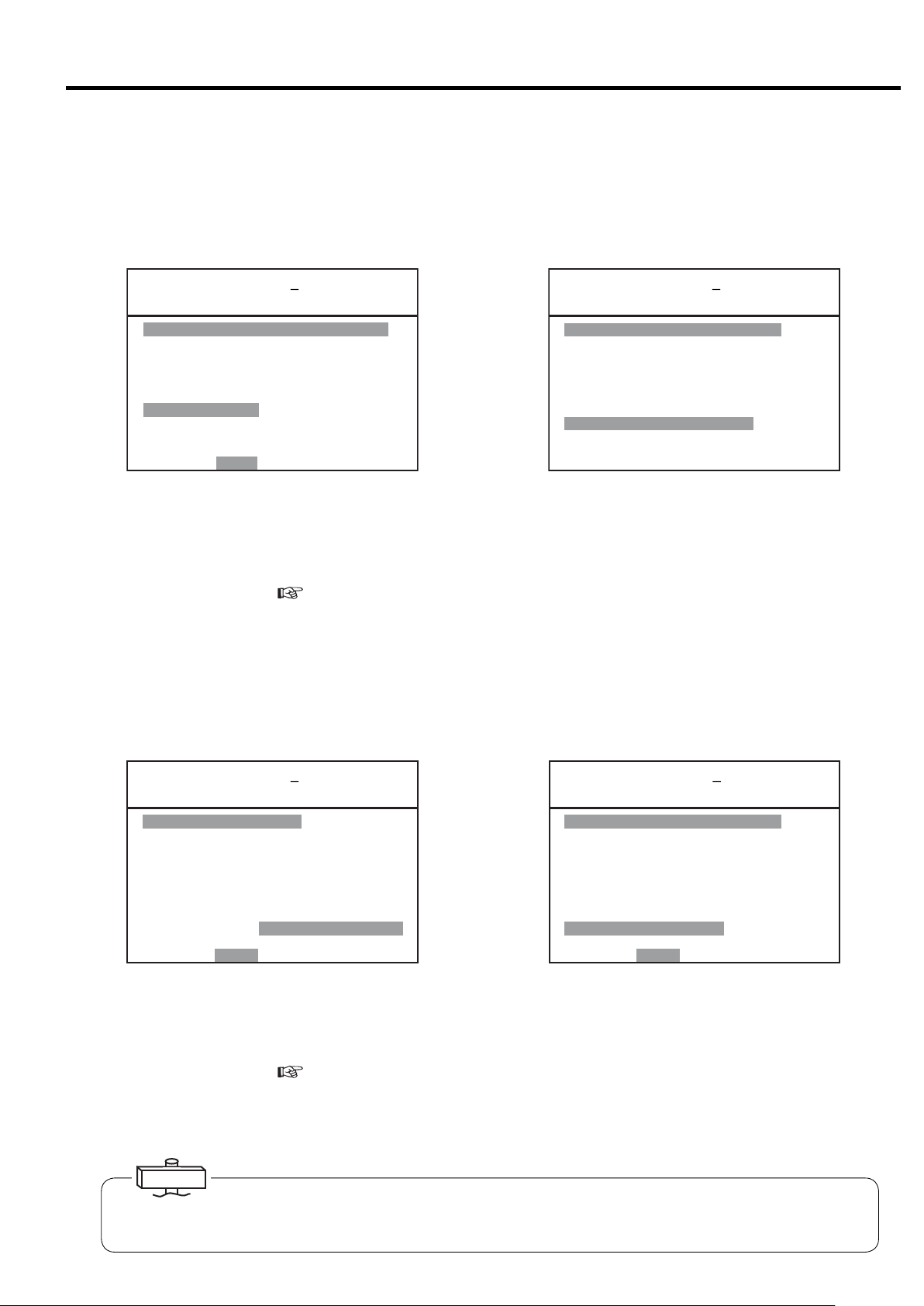
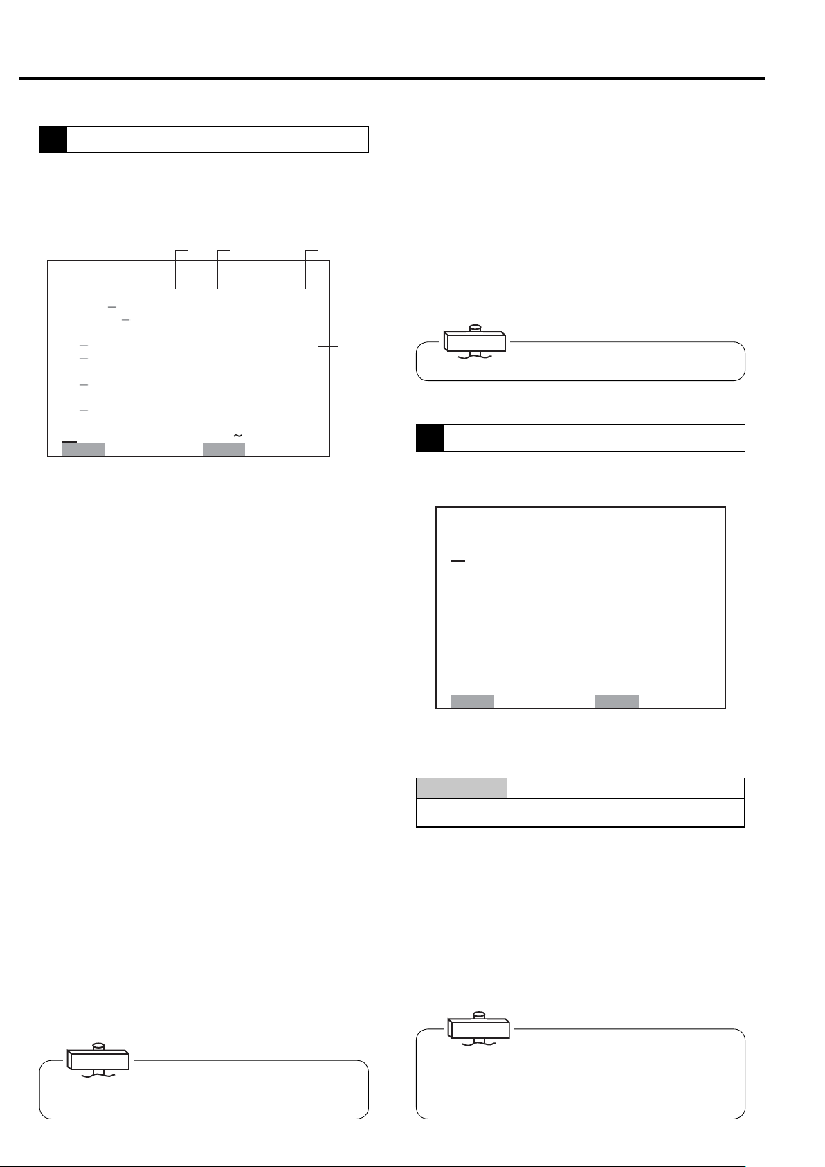
3.3.3 Message Displays
■ Shutdown Messages
① When a shutdown occurs for the compressor, the SHUTDOWN light and shutdown contents on the LCD monitor
(contents are displays on the left side and details are displayed on the right side) flash and the compressor stops running. There are 2 types of screens for shutdown: SHUTDOWN and FAILURE.
㻞㻜㻜㻣䠋㻜㻤䠋㻜㻝 㻝㻥䠖㻝㻥 㻖
㼀㼅㻼㻱 䠖 㼂㻿㻰㻭
㻰 㻵 㻿䠊㻼㻾㻱 㻿㻿 䠖 㻌 㻌 㻢 㻣㼜 㼟 㼕
䠘㻿 㻴 㼁 㼀 㻰 㻻 㼃 㻺䠚
㻯㻻㻻㻸㻭㻺 㼀 䠖
㻻㻵 㻸䠖
㻞䠪㻰 㻌 㻿㼁㻯㼀䠊㼀㻱㻹㻼
㻴㻵㻳㻴 㻌㻰㻵㻿䠊㼀㻱㻹㻼䠖
㻯 㻻 㻺 㼀 㻭 㻯 㼀 㻻 㻾 㻌㻱 㻾 㻾 䠖
㻻㼂㻱 㻾㻸 㻻㻭㻰 䠖
㻸㻻㼃 㻌 㼃 䠊 㻵 㻺㼀 㻿 㼀㻳 㻌 㻼䠊
㻰 㻾 㼅 㻱 㻾 㻌㻌㻌㻌 㼃 䠋 㻻 㻌 㻿 㻱 㻼 䠊
㻱㻸㻱㻹㻱 㻺㼀
㻼 㼞 㼑 㼟 㼟 㻾㻱 㻿 㻌 㼍 㼒 㼠 㼑 㼞 㻌 㻯㻴㻷䠊
㼀㼁
㻌
(Example)
In the case the thermal relay trips and the compressor stops
running, SHUTDOWN and OVERLOAD flash and the malfunction part of the main circuit is indicated.
㻞㻜㻜㻥䠋㻜㻤䠋㻜㻝 㻝㻥䠖㻝㻥 㻖
㼀㼅㻼㻱 䠖 㼂㻿㻰㻭㻌
㻰 㻵 㻿 䠊 㻼㻾 㻱 㻿 㻿 䠖 䚷䚷 㻢 㻣 㼜 㼟 㼕
䠘㻲 㻭 㻵 㻸 㼁 㻾 㻱䠚
㻿 㼅 㻿 㼀 㻱 㻹 㻱 㻾㻾 䠖 㼙㼙㼙㼙
㻿㼅㻿㼀㻱㻹 㻌 㻾㻱㼀㻾㼅
㻼㻯㻮㻌㻱㻾㻾䠖 㼚㼚㼚㼚㼚㼚
㻼㻾㻱㻿㻿䠊㻿㻺㻿㻾㻌 㻱㻾㻾䠖 㼛
㼀㻱㻹㻼䠊㻿㻺㻿㻾 㻱㻾㻾䠖 㼜
㻰䡅 㼟㼏㼛㼚㼚㼑㼏㼠 㼜㼛㼣㼑㼞
㼟㼚㼐 㼏㼛㼚㼠 㼍㼏 㼠
㼐 㼕 㼟 㼠 㼞 䡅㼎㼡 㼠㼛 㼞
㻌㻌 㻌㻌㻌
(Example)
Example of temperature sensor malfunction, sensor 1 disconnection FAILURE and TEMPERATURE SENSOR flash and
the location of the abnormality is indicated.
② Take the proper corrective action, and press the RESET button.
③ For further information,
see pages 33, 34.
NOTE) Malfunction detection of water failure is available for only water cooled single stage compressor. Malfunction
detection of dryer is available for only built-in dryer models. Malfunction detection of oil water separator and
element is not available.
■ Alarm Messages
① In the case an alarm occurs for the compressor, the ALARM light and contents / details displayed on alarm screen on
the LCD monitor flash and operation continues. There are 2 types of alarm screens: ALARM andPROBLEM.
㻞㻜㻜㻥䠋㻜㻤䠋㻜㻝 㻝㻥䠖㻝㻥 㻖
㼀㼅㻼㻱 䠖
㻰 㻵 㻿 䠊 㻼㻾 㻱 㻿 㻿 䠖 䚷䚷 㻢 㻣 㼜 㼟 㼕
䠘㻭 㻸 㻭 㻾 㻹䠚
㻰㻵 㻿䠊㼀㻱㻹㻼䠖䠄㻌 㻌 㻌 䠅㻖㻖㻖䉣
㻻㻵 㻸㻌 㼀㻱㻹㻼䠖 㻖㻖㻖䉣
㻸㻻㼃 㻌㻻䠊㻼䠊䠖 㻖䠊㻖 㻖㼜 㼟 㼕
㻯㻸㼀䠊㼀㻱㻹㻼䠊䠖 㻖㻖 㻖䉣
㻸㻻㼃 㻌 㻯㻸 㼀䠊 㻼 䠖 㻖 䠊 㻖 㻖 㼜 㼟 㼕
㻞䠪㻰 㻙 㻿䠊 㼀 㻱㻹㻼 㻌 㻲 㻵 㻺 㻙 㼀
㻸㻻㼃 㻌 㼃 䠊 㻸㻻㼃 㻌 㻻 㻵 㻸
㻰㻾㼅㻱㻾 㻭 㻵㻾 㻌㻲 㻵 㻸㼀㻱㻾
㻸䠊㻯㻻㼁㻺㼀 㻌 㻻㼂㻱 㻾 㻌㼃䠋㻻 㻌 㻿䠊
㻼㼞㼑㼟䡏㻾㻱㻿 㼍㼒㼠㼑㼞㻌㻯㻴㻷䠊
㻿㻰㻭㻌 㻌㻌 㻌㻌㻌
㼂
(Example)
In the case ALARM and AIR FILTER flash while the com-
㻞㻜㻜㻥䠋㻜㻤䠋㻜㻝 㻝㻥䠖㻝㻥 㻖
㼀㼅㻼㻱 䠖 㼂㻿㻰㻭㻌
㻰 㻵 㻿 䠊 㻼㻾 㻱 㻿 㻿 䠖 䚷䚷 㻢 㻣 㼜 㼟 㼕
䠘㻼 㻾 㻻 㻮 㻸 㻱 㻹䠚
㻯㻻㻺㻺㻱㻯 㼀 㻵 㻻㻺 㻌 㻱㻾㻾䠖 㻌 㻌 㻌
㻾㼑㼏㼛㼚㼚㼑㼏㼠 㻌 㼜㼛㼣㼑㼞䠊
㻹㼁㻸㼀䠥 㻙㼁 㻿㻱㼀 㻱㻾㻾
㻿㻯㻴㻱㻰㼁㻸㻱 㻌 㻿㻱 㼀 㻌 㻱㻾㻾
㻯㻻㻹䠊㻱㻾㻾㻌㻿㼀㻻㻼䠖㻌㻌㻌㻌㻌
㻯㻻㻹䠊㻱㻾㻾㻌㻭㻸㻹䠖 㻌㻌㻌㻌㻌
㻮㻭㼀㼀㻱㻾㼅 㻌㻻㼁㼀
㻼 㼞 㼑 㼟 㼟 㻾㻱 㻿 㼍 㼒 㼠 㼑 㼞 㻯 㻴㻷䠊
㻌㻌 㻌㻌㻌
(Example)
Example of battery replacement period.
pressor is running, it indicates the filter is clogged.
② Take the proper corrective action, and press the RESET button.
③ For further information,
see pages 33, 34.
NOTE) Malfunction detection of water failure is available for only water cooled single stage compressor. Malfunction
detection of dryer is available for only built-in dryer models. Malfunction detection of oil water separator and
element is not available.
IMPORTANT
ALARM and PROBLEM messages are treated as alarms, but aside from connection abnormalities that make operation impossible such as reverse phase and no phase when power is turned on, they also may indicate shutdown due to malfunction of the
communication status.
15

3. OPERATING THE DSP [How to Use the Liquid Crystal Display (LCD)]
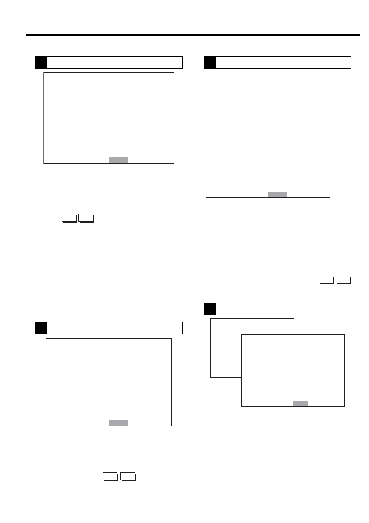
■ Messages of Automatic Stop Display and Automatic Restart Display
When the DSP air compressor has automatically stopped, the following screen is displayed, the AUTO START light
flashes/lights, and the RESTART message screen and details of contents flash on the LCD monitor.
● SCHEDULED STOP: Schedule operation setting
<AUTO light ON>
When schedule is set on the scheduled operation
㻞㻜㻜㻥䠋㻜㻤䠋㻜㻝 㻝㻥䠖㻜㻞 㻖
㼀㼅㻼㻱 䠖 㼂㻿㻰㻭㻌
㻰 㻵 㻿䠊 㻼㻾 㻱 㻿 㻿 䠖 䚷䚷 㻢 㻣 㼜 㼟 㼕
䠘㻾㻱㻿㼀㻭㻾㼀䠚
㻾 㻱 㻿 㼀 㻭 㻾 㼀 㻭 㼀 䠖 䠆䠆 䠖 䠆䠆
㻾㻱㻿㼀㻭㻾㼀 㼃㻭 㻵 㼀䠖 㻌 㻞㻣䡏
㻺㻻㼃䠈 㻿 㼀 㻻 㻼 㻼 㻱 㻰 䠞䠵 䠖
㻿㻯㻴㻱㻰㼁㻸㻱 㻿㼀㻻㻼
㻭㼁㼀㻻㻹㻭㼀 㻵 㻯 㻿 㼀㻻㻼
㻰㻾㼅㻱㻾 㻼㻾㻱㻿㼀㻭㻾㼀㻱㻰
㻰㼁㻭㻸䠋㻮㻭㻯㻷㼁㻼
㻵 㻼 㻵 㻌 㻾㻱㻿㼀㻭㻾㼀
㻯㼀㻸㻾䠊㻾㻱㼀㻾㼅
㻌㻌 㻌㻌㻌
screen, displays state of operation being stopped by
preset time. Operation starts automatically when the
preset restart time comes.
● LEAD/LAG OPERATION STOP
(Note: applies only to machines equipped with two-
unit alternate operation.)
<AUTO light ON>
When the operation control mode is set to dual or
backup on the operation mode setting screen, standby
status of the slave machine in dual or backup operation
is indicated.
● DRYER PRESTARTED
(Note: Applies only to machines equipped with a
built-in dryer.)
<AUTO START light flashes>
When dryer prestart is set, the dryer starts operating
in advance, and compressor stopped status is indicated.
RESTART WAIT time is counted down.
● AUTO OPERATION
(Note: Applies only to machines equipped with
AUTO function)
<AUTO START light ON>
Indicates status stopped by low load when set to
AUTO operation. AUTO START light flashes during
restart limit while stopped, and RESTART WAIT time
is counted down.
● INSTANT STOP / RETRY
(Note: Retry applies to V type only.)
<AUTO START light flashes>
Displays status of restart for instantaneous power
interruption (IPI) restart and V type retry.
RESTART WAIT time is counted down.
16
3. OPERATING THE DSP [How to Use the Liquid Crystal Display (LCD)]
■ Maintenance Notice Messages
A maintenance date is determined by the amount of total operating hours or an elapsed calendar period, whichever
comes first. When the maintenance date or time arrives, the maintenance notice message appears on the display under
the heading of MAINTenance.
This function is an alarm display only, and does not output alarm externally.
Replace suction throttle valve consumable parts when inspection maintenance is displayed or the 1 million unloader
count alarm is given, whichever comes first.
㻞㻜㻜㻥䠋㻜㻤䠋㻜㻝 㻝㻥䠖㻜㻞 㻖
㼀㼅㻼㻱 䠖 㼂㻿㻰㻭㻌
㻰 㻵 㻿䠊㻼㻾㻱 㻿㻿 䠖 㻌 㻌 㻢 㻣 㼜 㼟 㼕
䠘㻹㻱㻿㻿㻭㻳㻱䠚
㻹㻭 㻵 㻺 㼀䠊 䠖㻝 㼅㻱 㻭 㻾㻌 㻌
㻹㻭 㻵 㻺㼀 䠊䠯䠟䠤䠡䠠䠱 㻸 䠡 䠖 㻭
㻼 㼞 㼑 㼟 㼟㻿㻱 㼀 㻌 㼍 㼒 㼠 㼑 㼞 㻌 㻯㻴㻷䠊
㻹㻭 㻵 㻺 㼀䠊㻯㻻㻹㻼 㻸 㻱 㼀㻱 㻰
㻿㼃 㻵 㼀㻯㻴㻱㻰 㻌 㼀㻻 㻌 㻸㻻㻯㻭㻸
㻵 㻺 㻌 㻻㼂㻱㻾䠮㻵 㻰㻱 㻹㻻㻰㻱
㻵㻺㻌㼁㻺㻸㻻㻭㻰㻌㻿㼀㻻㻼
㻿㼃 㻵 㼀 㻯㻴 㻱 㻰 㻌 㼁 㻌 㻹㻻㻰 㻱
㻌㻌 㻌㻌㻌
(1)
(2)
(3)
Every these calendar periods: Service the DSP according to the schedules:
0.5 years, 1.5 years, 2.5 years
3.5 years, 4.5 years, 5.5 years
1.0 years, 5.0 years Yearly + Half-Yearly
2.0 years, 4.0 years 2-Yearly + Yearly + Half-Yearly
3.0 years 3-Yearly + Yearly + Half-Yearly
6.0 years (for overhauling)
Standard Maintenance Schedule (A) (for yearly 8,000-or-less operating hours)
A
Standard Maintenance Schedule (B) (for yearly 4,000-or-less operating hours)
B
Half-Yearly
6-Yearly + 3-Yearly + 2-Yearly + Yearly + Half-Yearly
CAUTION
If the inspection/maintenance is displayed, check the display contents, refer to maintenance standards
given in the compressor instruction manual and perform inspection/maintenance as soon as possible.
When inspection is complete, press and hold the SET button for at least 7 seconds.
The LCD monitor display contents then move to “Maintenance initial value completed” of the message
screen, and then return to the monitor screen 1 minute later.
NOTES:
1. MAINTenance can be reset, if the servicing is done earlier than expected and if the remaining operating time to next maintenance
is less than 2,000h in the case of A, 1,000h in the case of B.
2. On the contrary, if the servicing is done after the maintenance notice has appeared, the remaining operating hours to the next maintenance has been zero until the maintenance is done. After maintenance and resetting the counter, new counting time starts just
after the maintenance notice message has appeared on the display.
■ Other Messages
(1)SWITCHED TO LOCAL.
If set to local by remote operation following shut-
down restoration, operation automatically returns
to local when shutdown occurs, and the message is
displayed for 1 minute. For setting details, see
“3.4 How to Use the Digital Monitor.”
(
page 25)
(2) IN OVERRIDE MODE.
This message blinks when the DSP is in an over-
ride mode.
(3) UNLOAD STOP
If the UNLOAD STOP button is used, the display
flashes. The compressor unloads for 5 minutes and
then stops.
17
3. OPERATING THE DSP [How to Use the Liquid Crystal Display (LCD)]
3.3.4 How to Move within a Menu Display and to Change a Setting
ー [FUNCTION MENU] and [MAINTenance DATA MENU] ー
The method and procedure for altering settings is displayed using the following as an example.
How to Move within a [FUNCTION MENU] Display
1
㼇 㻲 㼁㻺㻯㼀 㻵 㻻㻺 㻹㻱㻺㼁 㼉
㻝䠊㻮㻭㻿 㻵 㻯㻌 㻿㻱 㼀㼁㻼
㻞 䠊㻹㼁 㻸 㼀 㻵 㻙 㼁㻺 㻵 㼀
㻟䠊㻯㻭㻼㻭㻯 㻵 㼀㼅 㻯㻻㻺㼀㻾㻻㻸
㻠䠊㻿㻯㻴㻱㻰㼁㻸 㻱
㻡䠊㻻㻼 㻱㻾 㻭㼀 㻵 㻻㻺 㻰 㻭㼀 㻭
㻢䠊㻸㻻㻭㻰 㻰㻭㼀㻭
㻣䠊㻭㻸㻭㻾㻹 㻴 㻵 㻿㼀㻻㻾㼅
㻤 䠊 㻿 㻴㼁㼀㻰㻻㼃㻺 㻴 㻵 㻿㼀 㻻㻾 㼅
1 – 2.
② Select the number of the item to be set with the
▽
△
③ Enter with the SET button. The display then switches
to the detail setting screen for that item.
The following explanation uses [2. Operation Mode
Setting Screen] as an example.
① Press the MENU button displayed on monitor screen
㻿㻱 㼀 䠖 㻻㻼㻱 㻺 㻹㻻㻺䠖 㻮㻭㻯㻷
How to Select or Change a Setting within a Setting Display
2
① When the display switches to the details screen, move
㼇㻹㼁㻸㼀 㻵 㻙㼁 㻌 㻿㻱㼀㼀 㻵 㻺㻳㼉
㻝
㻹㻻㻰 㻱 䠖 㻳㻸
㻞䠊㻰㼁㻭㻸㻌 㼀 㻵 㻹㻱䠖 㻌 㻤䠊
㻟䠊㻹㻱㼀㻴㻻㻰 䠖 㻭㻼
㻠䠊㻿㼃 㻵 㼀㻯㻴㻻㼂㻱㻾䠖 㻜 㻝 㻡 㼟
㻡䠊㻮㻭㻯㻷㼁㻼 䠖 䚷䚷䚷㻣㼜
㻢䠊㼁 㻺㻸㻻㻭㻰䠖 䚷䚷䚷㻟 㼜㼟 㼕
㻭㻸㼀䠊㼀㻵㻹㻱䠖㻌 㻠㻤㻜㻹㻵㻺
㻣
㻯㻻㻺㼀 㻾㻻 㻸 㻹㻻㻰 㻱 䠖 㻮
㻤
㻌 㻿㻺
㻜㼔
㻻㼂㻾 㻾㻸
㼟㼕
to the line to be altered with the
tons.
IMPORTANT
Items with a dash next to their number cannot be altered
on the LCD monitor. In this case, alter from the digital
monitor while referring to the instructions manual for the
compressor.
buttons.
△
▽
but-
㻿㻱㼀䠖㻿㼀㻻㻾㻱 㻌㻹㻻㻺䠖㻮㻭㻯㻷
①
㻝 㻹㻻㻰 㻱 䠖
㻞䠊㻰㼁㻭㻸㻌 㼀 㻵 㻹㻱䠖 㻌 㻤䠊㻜 㼔
㻟䠊㻹㻱㼀㻴㻻㻰 䠖
㻠䠊㻿㼃 㻵 㼀㻯㻴㻻㼂㻱㻾䠖 㻜 㻝 㻡 㼟
㻳㻸㻿㻺
㻭㻼㻻㼂㻾 㻾㻸
②
㻝 㻹㻻㻰 㻱 䠖
㻞䠊㻰㼁㻭㻸㻌 㼀 㻵 㻹㻱䠖 㻌 㻤䠊㻜 㼔
㻟䠊㻹㻱㼀㻴㻻㻰 䠖
㻠䠊㻿㼃 㻵 㼀㻯㻴㻻㼂㻱㻾䠖 㻜 㻝 㻡 㼟
㻳㻸㻿㻺
㻭㻼㻻㼂㻾 㻾㻸
③
㻝 㻹㻻㻰 㻱 䠖
㻞䠊㻰㼁㻭㻸㻌 㼀 㻵 㻹㻱䠖 㻌 㻡䠊㻜 㼔
㻟䠊㻹㻱㼀㻴㻻㻰 䠖
㻠䠊㻿㼃 㻵 㼀㻯㻴㻻㼂㻱㻾䠖 㻜 㻝 㻡 㼟
㻳㻸㻿㻺
㻭㻼㻻㼂㻾 㻾㻸
④
㻹㻻㻰 㻱 䠖
㻝
㻞䠊㻰㼁㻭㻸㻌 㼀 㻵 㻹㻱䠖 㻌 㻡䠊㻜 㼔
㻟䠊㻹㻱㼀㻴㻻㻰 䠖
㻠䠊㻿㼃 㻵 㼀㻯㻴㻻㼂㻱㻾䠖 㻜 㻝 㻡 㼟
㻳㻸㻿㻺
㻭㻼㻻㼂㻾 㻾㻸
Move to the item to be altered with the
②
▽
③
Alter the setting value with the
△
④ After altering the setting value, press the SET button.
The cursor moves to the number.
⑤ Press the SET button again.
The cursor moves to the first number at the top of the
screen and the setting contents are entered.
When setting is complete, pressing the MONITOR button once returns the display to the MENU screen, and
pressing it again returns to MONITOR screen 1.
The same procedure is used to alter settings for other
menus.
IMPORTANT
When altering settings of the LCD screen, number update
by button operation is slow. Press the buttons slowly
when altering settings.
⑤
㻝 㻹㻻㻰 㻱 䠖
㻞䠊㻰㼁㻭㻸㻌 㼀 㻵 㻹㻱䠖 㻌 㻡䠊㻜 㼔
㻟䠊㻹㻱㼀㻴㻻㻰 䠖
㻠䠊㻿㼃 㻵 㼀㻯㻴㻻㼂㻱㻾䠖 㻜 㻝 㻡 㼟
㻳㻸㻿㻺
㻭㻼㻻㼂㻾 㻾㻸
button.
▽
buttons.
18
3. OPERATING THE DSP [How to Use the Liquid Crystal Display (LCD)]
3.3.5 [FUNCTION MENU] −Setting Displays
Model Setting Confirmation
1
㼇㻮㻭㻿㻵㻯 㻿㻱㼀㼁㻼㼉
㼂㻱㻾䠊䠖 㻡䠊㻜
㻿㻱㻾 㻵 㻱㻿 㻺㻭㻹㻱䠖 㻰㻿㻼
㻯㻻㻻㻸 㻵 㻺㻳 㻹㻱 㼀㻴㻻㻰䠖 㼃㼀㻾
㻺㻻䠊㻻㻲 㻿 㼀㻭 㻳㻱 䠖 㻌 㻞
㻼㻙㻿㻼㻱㻯䠖 䚷㻝 㻜㻜㼜㼟㼕
㻼 䠊 㻰 㻭 㼀 㻭 䠖 䚷䚷 㻢 㻤 㼜 㼟 㼕
䠟䠰䠖 㻞㻡㻜䠝
㻯㻸 㼀䠊㻰 㻱 㻸 㻭㼅 䠖 㻌 㻡 㼟
㻵㻼㻵䠖 㻵㻵㻵
㻭㻰㻾 㻱 㻿 㻿 㻺㻻䠊 䠖 㻌 㻝
㻹㻻㻺 䠖 㻮㻭㻯㻷
IMPORTANT
The screen provides the model and serves as a target for
setting status. Check the screen when making an inquiry.
㻡䠊㻜
①
②
③
④
⑤
⑥
⑦
⑧
⑨
⑩
The starter of settings can be confirm the software,
model and setting status of model-specific settings such
as capacity control. (Double asterisks are displayed for
settings that do not require confirmation.)
① Indicates board software version.
② Indicates compressor type.
③ Displays cooling type.
④ Displays the number of compressor stages.
⑤ Displays pressure specification.
⑥ Displays interstage pressure.
⑦ Indicates CT setting value.
⑧ Displays water failure detection conditions for water
cooled compressor.
⑨ Displays status of instantaneous power interruption
(IPI) restart setting.
Displays compressor number. (Must be distinguished by
⑩
number is using communication function.)
Operation Mode Settings
2
Confirm settings by compressor alternate operation
specifications and multiple unit control (communication
support). Wiring must be supplied separately for use.
Items for which a dash is displayed next to their number cannot be set on the LCD monitor.
㼇㻹㼁㻸㼀 㻵 㻙㼁 㻌 㻿㻱㼀㼀 㻵 㻺㻳㼉
㻝
㻹㻻㻰 㻱 䠖 㻳㻸
㻞䠊㻰㼁㻭㻸㻌 㼀 㻵 㻹㻱䠖 㻌 㻤䠊
㻟䠊㻹㻱㼀㻴㻻㻰 䠖 㻭㻼
㻠䠊㻿㼃 㻵 㼀㻯㻴㻻㼂㻱㻾䠖 㻜 㻝 㻡 㼟
㻡䠊㻮㻭㻯㻷㼁㻼 䠖 㻌 㻌 㻌 㻣㼜
㻢䠊㼁 㻺㻸㻻㻭㻰䠖 㻌 㻌 㻌 㻟㼜 㼟 㼕
㻭㻸㼀䠊㼀㻵㻹㻱䠖㻌 㻠㻤㻜㻹㻵㻺
㻣
㻯㻻㻺㼀 㻾㻻 㻸 㻹㻻㻰 㻱 䠖 㻮
㻤
㻿㻱㼀䠖㻿㼀㻻㻾㻱 㻌㻹㻻㻺䠖㻮㻭㻯㻷
㻌 㻿㻺
㻜㼔
㻻㼂㻾 㻾㻸
㼟㼕
1. Operation control: Set operation control is dis-
played on the digital monitor.
IMPORTANT
If using the backup function, switch to the digital monitor and set.
2. LEAD/LAG operation time: Time setting for alter-
nate operation of a pair of compressors (setting
range: 0.1 – 99.9 hours; initial value: 8.0)
3. Switching conditions: Setting of conditions for
switching operation between a pair of compressors
4. Switching time: Switching time setting if switch-
ing conditions are “parallel” or “interval” (setting
range: 5 – 300 seconds, initial value: 15)
Single Operates compressor independently.
Case where multiple unit control is executed by communication
STPR
Multiple
()
Backup
OVER LAP
Interval
function of multi roller EX (dedicated panel of NEXT Series).
Unit control is executed by RS485 communication according to
unit
the settings. Requires separate setting of compressor number.
Operation alternates between a pair of compressors for
Dual
a preset amount of time. AUTO light lights.
Operation mode that adds pressure backup function to
dual operation. When pressure drops, the slave machine
starts. AUTO light lights.
Method whereby first compressor is stopped after switching time for
the other unit in parallel operation when it is time for dual operation.
Method of operating the other compressor after stopping the
first one after switching time when it is time for dual operation.
5. BACKUP: Setting of pressure to start the backup
compressor when set to backup operation (range: 0.00
– 72 psi, initial value: 7, difference from recovery pressure in the minus direction).
6. UNLOAD:
Pressure setting that manually unloads 1 unit
when the preset pressure is reached in backup operation
(range: 0.00 – 72 psi, initial value: 3, difference from control pressure in the minus direction).
7. DUAL TIME:
Displays time remaining until switch for
dual / backup operation. Time is not counted down
when operating 2 units for backup operation. When
operation is stopped, remaining time is maintained.
8.
SPEED CONTROL MODE: Displays control mode of V
type. An asterisk is displayed for the Fixed speed type.
IMPORTANT
Altered setting values can only be entered when the compressor is not running.
19
3. OPERATING THE DSP [How to Use the Liquid Crystal Display (LCD)]
Capacity CONTROL SETTING Display
3
Screen for confirming pressure settings for capacity control. Pressure settings are set from the digital monitor.
Pressure settings consist of setting 1 and setting 2,
which can be used by setting time used.
①② ③
㼇 㻯㻻㻺 㼀㻾㻻㻸 㻿 㻱 㼀 㼀 㻵 㻺㻳 㼉
㻝䠊㼀㼅㻼㻱䠖㼂㻭 㼎㼎㼎 㼏㼏㼏
㻞䠊䠬
㻟䠊䠬 㻵
㻠
㻡
㻢
㻣
㻤䠊㼀 㻵㻹㻱䠖㻝㻤䠖㻜㻜
㻿㻱㼀䠖㻿㼀㻻㻾㻱 㻌㻹㻻㻺䠖㻮㻭㻯㻷
㻸㻻㻿㻿 䠖 㻖 䠊 㻖 㻖 㼜 㼟 㼕
㻯㻭䠖㻖㻖㻖 㻖㻖䠊㻖䡉㻟
䠄㻯㻻㻺㼀㻾㻻㻸䠋㻯㼁㼀㻙 㻵 㻺 㻕
㻼㻝䠖 㻌 㻝 㻜㻜䠋㻌 㻌 㻤㻣㼜㼟 㼕
㻼㻞䠖 㻌 㻝 㻜㻜䠋㻌 㻌 㻤㻣㼜㼟 㼕
䠄㼀㻭㻾㻳㻱㼀㻌 㻼㻝䠋㻼㻞 㻕
㼀㻭㻾㻳㻱 㼀 䠖
㻌㻌 㻥㻤䠋㻌㻌 㻥㻤㼜㼟㼕
㼀㻵㻹㻱㻌㻸 㻵㻹㻵 㼀䠖 㻜㻟㻜㼟
䠄㻼 㻞 㻱 㻲㻲㻱㻯㼀 㻵 㼂㻱 㻕
㻞㻞䠖㻜㻜
④
⑤
⑥
1. TYPE: Displays setting data for capacity control.
① Control settings set by the digital monitor can be con-
firmed.
Fixed speed type: I (load/unload operation) / IP (AUTO
operation specifications * optional)
V type: VB (AUTO function off)/ VA (AUTO operation
specifications)
② Setting type of pressure set by the digital monitor can
be confirmed.
SETTING 1: Standard pressure setting;
SETTING 2: 2nd pressure setting
EXT: External load/unload setting
AUTO: Switches setting 1 and setting 2 by time.
③ Sets optional conditions. With standard specifications,
displays “ordinary” characters.
2 - 3. OPTION: Used for options.
4 - 6. PRESSURE SETTING: Pressure settings set by
the digital monitor, target pressure and time limit can be
confirmed all at once on the LCD monitor. ④
7. TIME LIMIT: (Fixed speed type only)
Preset time limit can be confirmed.
The time limit is effective when ECOMODE (energy
conservation mode) is selected by pressing and holding
the DISPLAY SWITCH button for at least 7 seconds.
The function sets energy conservation mode until control pressure (unload start pressure) drops to the target
value if the load and unload repeat time clears the time
limit. If control pressure and recovery pressure change
time is measured and it exceeds the time limit, control
pressure is lowered so the time limit is no longer
exceeded. ⑤
(Time limit range: 30 - 120 seconds; initial value: 30 seconds)
8. USE TIME: Sets time to use pressure of setting 2. At
that time, it displays automatic at the position of (2) of
the type. When start and stop time become the same
value, the automatic display is returned to setting 1 and
the function is stopped.
IMPORTANT
Settings are selectable when the DSP is in a stop.
Schedule Setting
4
Scheduled operation can be set for 1 day (standard equipment).
㼇 㻿㻯㻴㻱㻰㼁㻸㻱 㻌 㻿 㻱 㼀㼀 㻵 㻺㻳 㼉
㻝䠊㻹㻻㻰㻱 䠖 㻯㻴㻱㻰㼁㻸 㻱
㻿㼀㻭㻾㼀 㻿㼀㻿㻻㻼
䠄㻝䠅㻜㻣䠖㻜㻜㻌 㼅 㻞㻜䠖㻜㻜 㻌 㼅
䠄㻞䠅㻜㻜䠖㻜㻜㻌 㻺 㻜㻜䠖㻜㻜 㻌 㻺
䠄㻟䠅㻜㻜䠖㻜㻜㻌 㻺 㻜㻜䠖㻜㻜 㻌 㻺
䠄㻠䠅㻜㻜䠖㻜㻜㻌 㻺 㻜㻜䠖㻜㻜 㻌 㻺
䠄㻡䠅㻜㻜䠖㻜㻜㻌 㻺 㻜㻜䠖㻜㻜 㻌 㻺
㻞䠊㻾㻱㻯㻻㻾㻰 㻝䠖 㻝㻜䠖㻜㻜
㻟䠊㻾㻱㻯㻻㻾㻰 㻞䠖 㻝㻥䠖㻜㻜
㻿㻱㼀䠖㻿㼀㻻㻾㻱 㻌㻹㻻㻺䠖㻮㻭㻯㻷
The display shows an example setting of scheduled operation from 7:00 to 20:00. “19:07” indicates the current time
㻝㻥䠖㻜㻣
1. MODE: Scheduling Mode
OFF
SCHEDULED
Operates the DSP without a schedule.
Operates the DSP according to a daily 24hour calendar.
1. to 5. : Five Start/Stop Time Patterns
・ START: Starting Time
・ STOP: Stopping Time
・ Y or N :Yes starts or stops as scheduled.
2. DATA MEASUREMENT TIME: Time for recording
operation data twice a day can be set.
Recorded operation data can be confirmed by the “5”
operation data record screen.
IMPORTANT
IMPORTANT
If the time limit is altered, consult with your dealer or the
Hitachi Service Station given on the rear cover.
20
If “SCHEDULE” is set, the AUTO light lights. If there is no
valid setting for time, the AUTO light flashes. Altered setting can only be entered when the compressor is not running.
3. OPERATING THE DSP [How to Use the Liquid Crystal Display (LCD)]
Operation Data Display
5
㼇 㻻㻼㻱 㻾㻭㼀 㻵 㻻㻺 㻰 㻭㼀 㻭 㼉
㻝䠊㻜㻤䠋㻜㻝 㻝㻜䠖㻜㻜
㻼䠖㻌 㻢㻣䚸㻌 㻢㻤䚸㻖㻖㻖䚸㻖㻖㻖
㻯䠖 㻜
㼀䠖 㻣㻣䚸 㻥㻝䚸㻖㻖䚸㻖㻖䚸㻖㻖
㻸䠖 㻡 㻥䚸㻝 㻤䠊㻤
㻞䠊㼍㼍䠋㼎㼎 㼏㼏䠖㼐㼐
㻼䠖㻖㻖㻖䚸㻖㻖㻖䚸㻖㻖㻖䚸㻖㻖㻖
㻯䠖㻖㻖㻖
㼀䠖㻖㻖㻖䚸㻖㻖㻖䚸㻖㻖䚸㻖㻖䚸㻖㻖
㻸䠖㻖㻖㻖䚸㻖㻖㻖㻖㻖
㻹㻻㻺 䠖 㻮㻭 㻯㻷
Records date/time, pressure, current, temperature and
load status at that time as operating state recorded by
data measurement time. Up to 12 times can be recorded,
after which the oldest data is deleted one at a time; the
latest data is displayed for item 1. The screen shows
record for 2 times, and the necessary data can be con-
▽
firmed by
△
button operation. If altered before
time is up, the data prior to change is maintained, and the
time recorded as soon as the data is altered changes.
1. and 2. - :Indicates the MONTH / DAY HOUR: MINUTE.
P - Represents a pressure (psi) and indicates, from left to
right, the: Discharge air pressure, pressure data.
C - Current (A).
T - Represents a temperature (℉)and indicates from
left to right: 1st stage discharge air temperature, 2nd
stage discharge air temperature.
L -
Represents a load ratio percentage (%). and out put (kW).
If there is no data, an asterisk is displayed.
Alarm History
7
If an alarm occurs on the digital monitor, shutdown history is recorded. Up to 6 items of alarm history however
can be recorded aside from shutdown history. Contents
and occurrence state can be confirmed.
㼇 㻭 㻸 㻭 㻾㻹 㻴 㻵 㻿 㼀㻻㻾 㼅 㼉
㻝䠊 㼍㼍㼍㼍㼍㼍㼍㼍㼍㼍㼍㼍㼍
㻯㻻㻰㻱䠖㻞㻝㻸 㻺㻻㻿䠊䠖㻌 㻝
㻜㻣䠋㻜㻤䠋㻜㻝 㻝㻥䠖 㻞㻢
㻞䠊 㻖㻖㻖㻖㻖㻖㻖㻖㻖㻖㻖㻖㻖
㻯㻻㻰㻱䠖㻖㻖㻖 㻺㻻㻿䠊䠖㻖㻖
㻖㻖䠋㻖㻖䠋㻖㻖 㻖㻖䠖 㻖㻖
㻟䠊 㻖㻖㻖㻖㻖㻖㻖㻖㻖㻖㻖㻖㻖
㻯㻻㻰㻱䠖㻖㻖㻖 㻺㻻㻿䠊䠖㻖㻖
㻖㻖䠋㻖㻖䠋㻖㻖 㻖㻖䠖 㻖㻖
㻹㻻㻺 䠖 㻮㻭㻯㻷
①
① Operation state is indicated by a symbol next to the
shutdown code.
L: Load, U: Unload, S: Stop
Displays alarm contents and code, date, time, state and
how many times alarm occurred. If the same alarm continues to occur, it is overwritten as update data, and the
number of times the alarm occurs is updated. The latest
warning is recorded as item 1. If there is no alarm, asterisks are displayed. The screen displays data for 3 types,
▽
and the necessary data can be confirmed by
△
button operation.
Shutdown History Display
8
Load Data Display
6
㼇 㻸㻻㻭㻰 㻰㻭㼀㻭 㼉
㻝䠊㻜㻤䠋㻜㻝
㻭㼂㻳䠊㻼㻾 㻱 㻿㻿 䠖 㻌 㻌 㻣 㻡 㼜 㼟 㼕
㻭㼂㻳䠊㻯㼁㻾㻾㻱㻺㼀䠖 㻜㻠㻜䠝
㻭㼂㻳䠊㻸㻻㻭㻰 㻾㻭㼀㻱䠖㻜㻢㻡䠂
㻭 㼂 㻳 䠊 㻼 䠫䠳 䠡 䠮 䠖 㻌 㻝 㻣 㻚 㻤 㼗 㼃
㻞䠊㻜㻝䠋㻜㻝
㻭㼂㻳䠊㻼㻾 㻱 㻿㻿 䠖 㻌 㻌 㻣 㻡 㼜 㼟 㼕
㻭㼂㻳䠊㻯㼁㻾㻾㻱㻺㼀䠖 㻜㻠㻜䠝
㻭㼂㻳䠊㻸㻻㻭㻰 㻾㻭㼀㻱䠖㻜㻢㻡䠂
㻭 㼂 㻳 䠊 㻼 䠫䠳 䠡 䠮 䠖 㻌 㻝 㻣 㻚 㻤 㼗 㼃
㻹㻻㻺 䠖 㻮㻭㻯㻷
This display shows the averaged load data per day. Data
can be recorded for a maximum of six days; the 7th day of
averaged loaded data is automatically deleted and the 1st
or most recent day of averaged data is added. The most
recent data is arranged at the top of the display.
The screen shows record for 2 times, and the necessary
▽
data can be confirmed by
△
button operation.
Data is averaged from operation start to stop. The average is however fixed at 0.00 minutes in the case of 24
hours operation.
㼇 㻲㼁㻺㻯 㼀 㻵 㻻㻺 㻹㻱 㻺㼁 㼉
㻝䠊㻮㻭㻿 㻵 㻯㻌 㻿㻱 㼀㼁㻼
㻞䠊㻹 㼁㻸 㼀 㻵 㻙 㼁 㻺 㻵 㼀
㻟䠊㻯㻭㻼㻭㻯㻵 㼀㼅 㻯㻻㻺㼀㻾㻻㻸
㻠䠊㻿㻯㻴㻱㻰㼁 㻸㻱
㻡䠊㻻㻼㻱㻾㻭㼀㻵 㻻㻺 㻰㻭㼀㻭
㻢䠊㻸 㻻㻭㻰 㻰㻭㼀 㻭
㻣䠊㻭㻸㻭㻾㻹 㻴 㻵 㻿㼀㻻㻾㼅
㻤䠊 㻿 㻴㼁 㼀㻰 㻻㼃㻺 㻴 㻵 㻿㼀 㻻㻾 㼅
㻿㻱㼀䠖㻻㻼㻱㻺 㻹㻻㻺䠖㻮㻭㻯㻷
㼇㻰㻱 㼀㻭 㻵 㻸㻿 㼉
㻝䠊 㼍㼍㼍㼍㼍㼍㼍㼍㼍㼍㼍㼍㼍
㻰 㻵 㻿䠊㻼㻾㻱㻿 䠖 㻌 㻌 㻠 㻤 㼜㼟 㼕
㻵 㻺 㼀㻿 㼀㻳䠊 㻼 䠖 㻖 䠊 㻖 㻖 㼜 㼟 㼕
㻻 㻵 㻸 㻼㻾㻱㻿 䠖 㻖䠊 㻖 㻖 㼜 㼟 㼕
㻯㻸 㼀䠊㻼㻾㻱㻿 䠖 㻖䠊 㻖 㻖 㼜 㼟 㼕
㻰㻵 㻿䠊㼀㻱㻹㻼䠊㻝䠖 㻝㻤㻜䉣
㻰㻵 㻿䠊㼀㻱㻹㻼䠊㻞䠖 㻝㻤㻜䉣
㻻㻵 㻸 㼀㻱㻹㻼䠖 㻖㻖㻖䉣
㻯㻸 㼀䠊 㼀㻱 㻹㻼䠖 㻖 㻖 㻖 䉣
㻞㻺㻰 㻿 㼁㻯㼀䠊㼀 䠖 㻖㻖 㻖 䉣
㻯㼁㻾㻾㻱㻺㼀䠖 㻝 㻜㻜㻭
㻹㻻㻺 䠖 㻮 㻭㻯 㻷
Up to 6 items of alarm history are recorded aside from
shutdown history. Contents and occurrence state can be
confirmed. Select the number of the shutdown on the
SHUTDOWN HISTORY screen, press the SET button
and the operation state when the shutdown occurred can
furthermore be confirmed on the details screen.
● How to clear shutdown and alarm history.
If you want to clear the entire shutdown history and
alarm history, set F041 from the F mode of the digital
monitor to “1: CLEAR HISTORY” while referring to
the instructions manual of the compressor.
21
3. OPERATING THE DSP [How to Use the Liquid Crystal Display (LCD)]
3.3.6 Other Hardware Setting
Initial Setting
The calendar and clock are set by Hitachi prior to
delivery. To reset the calendar and clock, please contact the local Hitachi distributor.
Brightness Adjusting
Adjust the LCD brightness as follows:
To brighten:
Hold down the SET button and press the
MONITOR button.
To darken:
Hold down the SET button and press the
FUNCTION button.
Digital Monitor Operation Classification
The following is a table of contents that can be set by
the LCD monitor and digital monitor (next section).
Function Item
Operation Mode
Screen
Capacity Control
Screen
Scheduled Operation
Screen
Other Settings
Reset
Mode
Dual operation time
Switch conditions
Switch time
Backup pressure
Unload
Dual operation remaining time
Speed control mode
Type (Left: Capacity control)
Type (Center: Setting type)
Type (Right: Function)
Pressure loss
Total piping capacity
Control pressure
Recovery pressure
Target pressure
Time limit
Setting 2: Use time
Contents
Start/stop time
Data measurement time
Compressor No. setting
Instantaneous power interruption (IPI) setting
Remote operation setting
Dryer operation setting
AUTO operation setting
Energy saving mode setting
Shutdown/alarm reset
Load count reset
Maintenance reset
Shutdown/alarm history clear
3-Language Display Switch
The language of the display can be switched to
Japanese, English or Chinese by the dip switch on the
back of the LCD monitor board. If the language needs
to be changed, consult with your dealer or the Hitachi
Service Station given on the rear cover.
Power must be turned off before changing setting.
LCD monitor oper-
ation
− ○ F000
○
○
○
○
○
△(AUTO change)
−
○
○
○
−
○
○
○
○
−
○−
− ○ F041
Bit
Japanese setting
English setting
Chinese setting
Test mode
Digital monitor
(F mode)
−
○(Factory set)
○ F019
○ F018
−
○ F022 〜
○ F022 〜
○ F022 〜
○(Factory set)
−
○ F001
○ F002 〜
○ F005 〜
○ F008 〜
○ F011 〜
○
○
○
1234〜 8
OFF OFF
ON OFF
OFF ON
ON ON
Remarks
Dual, backup, etc.
Differential pressure
Differential pressure
V type only
Example: I type (load/unload type)
Example: Setting 1
Option (not supported)
Option (not supported)
Option (not supported)
Setting 1, Setting 2
Setting 1, Setting 2
Pressure differential
Energy saving mode decision time
Function switch
Operation data measurement
Display switch button operation
Reset button operation
Remote + display switch button
Set button 7 sec. ON
Not used
22
3. OPERATING THE DSP [How to Use the Digital Monitor]
3.4 How to Use the Digital Monitor
3.4.1 How to display operation status, shutdown history, and status of various settings
All display contents of the digital monitor are linked with the LCD monitor. All of the following display contents can be
can be confirmed by the LCD monitor.
Use the following operations to display the contents of other operation/setting status on the LCD monitor and simply
confirm operation status and setting status by the digital monitor.
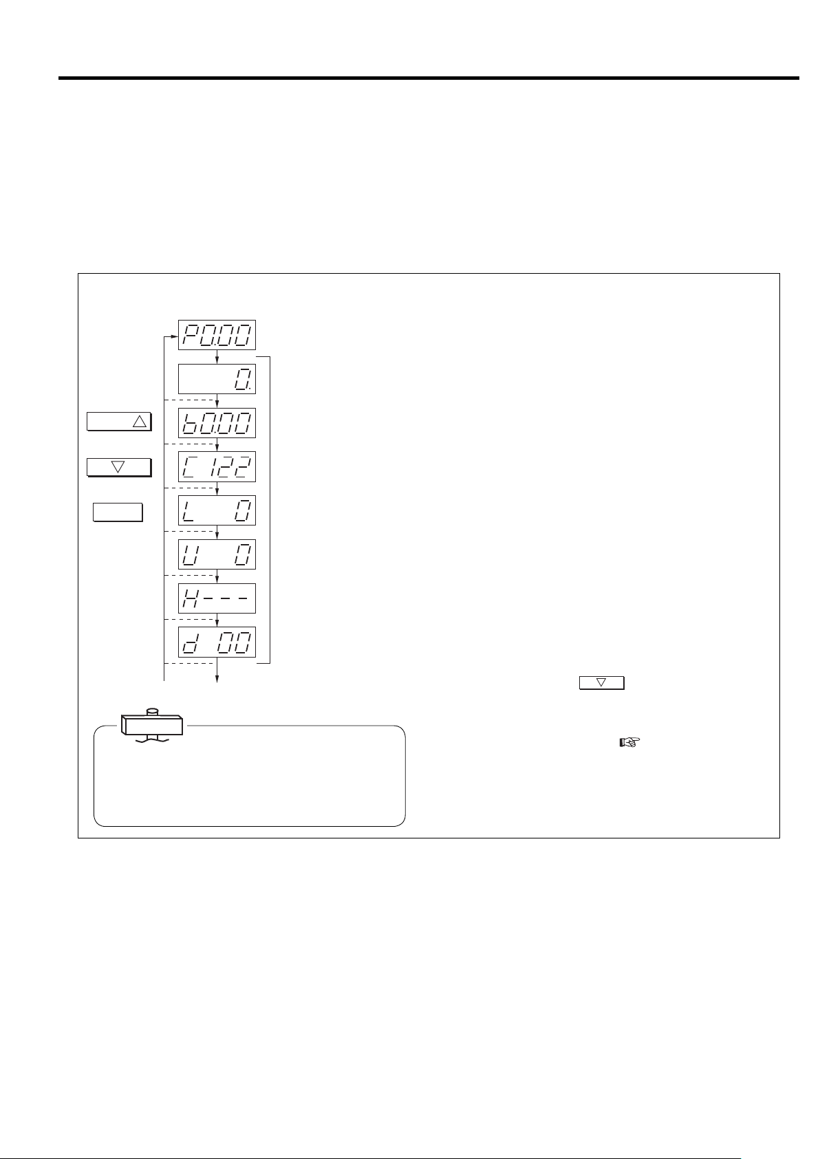
(1) How to Display the Operation Status
P: Dischargepressure(psi)
PressSWITCHDISPLAY.
Flasheswhenoperationtimeisadded.
Operationtime(×10)
表示切替
Proceedsby1each
Returnsby1each
Returnstodischarge
1
timepressed.
2
timepressed.
リセット
pressure.
b: Interstagepressure(psi)
C:Compressordischarge
temperature(℉)
(122℉)
L: Loadrate(%)
U: Loadcount(×10,000times)
H: Notused(displayonly)
d:Notused(displayonly)
Toshutdownhistorydisplay
IMPORTANT
1. When other than P0.00 is displayed, automatically
returns to P0.00 discharge pressure display in 3 minutes.
2. Load rate is a reference value determined by computation.
When the power is turned on, discharge pressure is displayed
on the screen of the digital monitor. Use the following proce-
dure to switch the digital monitor to other display.
Press the
①
SWITCH DISPLAY
button. Operation time is
then displayed on the screen.
Press the
②
SWITCH DISPLAY
button. Interstage pressure
is then displayed on the screen together with “b.”
③ Press the SWITCH DISPLAY button. Compressor discharge
temperature is then displayed on the screen together with
“C.”
Press the
④
SWITCH DISPLAY
button. Load rate is then dis-
played on the screen together with “L.”
Press the
⑤
SWITCH DISPLAY
button. Load count is then
displayed on the screen in units of 10,000 times together
with “U.”
Each time the SWITCH DISPLAY button is subsequently
pressed, it continues on to (2) Display of shutdown history
and (3) Monitor display of various settings. To return one
2
item at a time, press
. To return to discharge pres-
sure, press RESET.
● If the alarm or shutdown light is flashing, the shutdown code
is displayed along with “E0” (
page 33, 34).
“E0” indicates the contents of the latest shutdown.
● If the alarm or shutdown light is flashing, it indicates that
the alarm or shutdown has not been reset. Check E0.XX and
reset.
23
3. OPERATING THE DSP [How to Use the Digital Monitor]
(2) How to Display Shutdown History
Use the following procedure to display shutdown history on the
Dischargepressuredisplay
表示切替
Proceedsby1each
Returnsby1each
Returnstodischarge
1
timepressed.
2
timepressed.
リセット
pressure.
SWITCHDISPLAY
1
Press8times.
[Localshutdown]
[1priorshutdown]
XX : Shutdowncode
[Oldestshutdown]
Historyconsistsof6items.
Notused(displayonly)
screen.
①
② Press the SWITCH DISPLAY button. “E1.” is then dis-
③ Press the RESET Button. The screen then returns to the
Press the
SWITCH DISPLAY
displayed together with the shutdown code (
button 8 times. “E0.” is the
page 33,
34). “0” indicates the latest shutdown. (Automatically chang-
es to “E.0” when shutdown or alarm occurs.)
played along with the shutdown code. “1” indicates shut-
down that occurred previously. Six items of data from 0 – 5
are recorded. “E5” indicates the oldest shutdown.
usual digital monitor display.
IMPORTANT
Notused(displayonly)
If the shutdown code “XX ”is “ ” it means there is no
shutdown history. Also, when anything other than shutdown history is displayed without resetting shutdown,
Todisplayofvarioussettings
it returns to the latest shutdown history in 3 minutes.
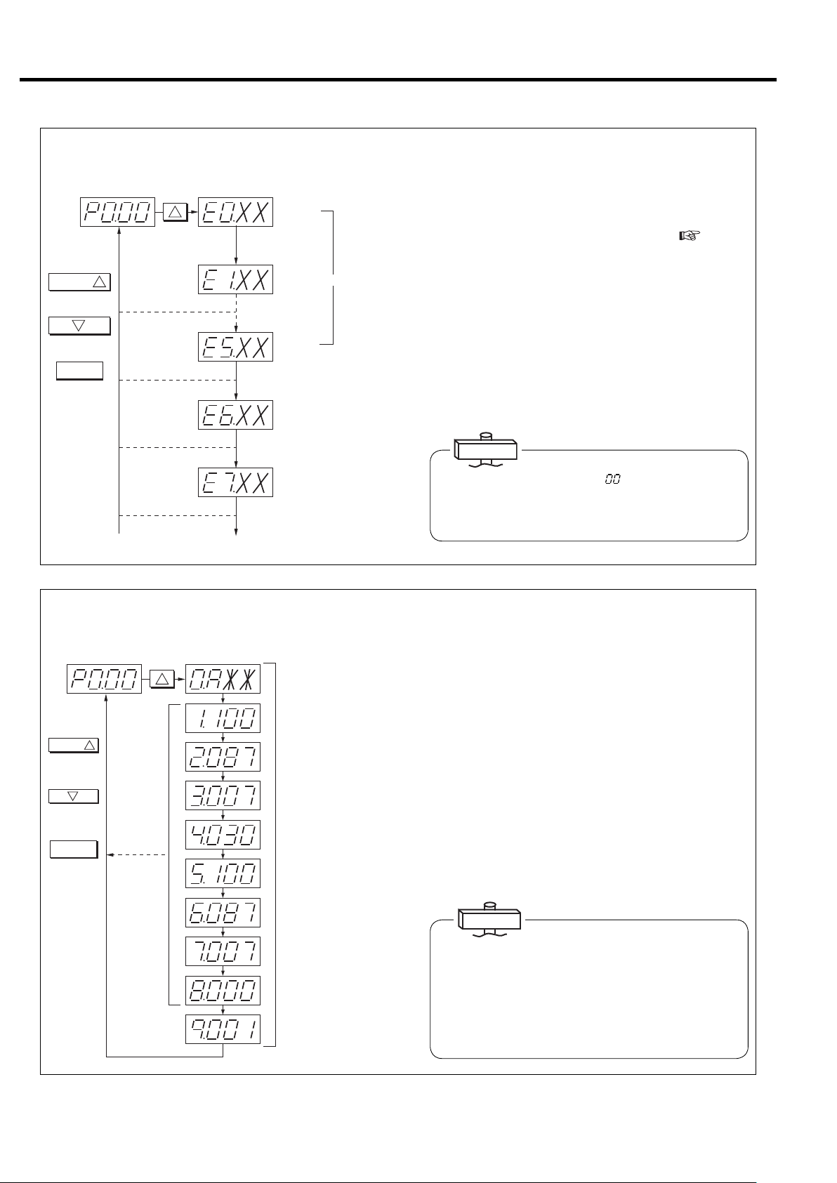
(3) How to Display Various Settings (Perform operation only when confirmation is
necessary.)
Dischargepressuredisplay
表示切替
1
Proceedsby1
eachtimepressed.
2
Returnsby1each
timepressed.
リセット
Returnsto
dischargepressure.
SWITCHDISPLAY
1
Press16times.
No.0 : Controlstatus
A : Capacitycontroltype
No.1 : Startpressure1
100 : 100psi
No.2 : Recoverpressure1
087 : 87psi
No.3 : Pressuredifferential1
007 : 7psi
No.4 : ECOMODE
[Energyconservationmode]
Decisiontime
No.5 : Startpressure2
100 : 100psi
Use the following procedure to display capacity control type
and pressure setting values for confirmation.
Press the
①
SWITCH DISPLAY
button 16 times. “0.A**” is
then displayed on the screen. ** changes with specifica-
tions. “A” may be “L” or “U” depending on capacity control
specifications.
② Consists of items 0 - 9. Pressure setting status and optional
pressure setting 2 can be confirmed each time the SWITCH
DISPLAY button is pressed.
③ Press the RESET Button. The screen then returns to the
usual discharge pressure display.
24
No.6 : Recoverpressure2
087 : 87psi
No.7 : Pressuredifferential2
007 : 7psi
No.8 : Instantaneouspower
interruption(IPI)setting
Invalid
000
:
No.9 : Compressoraddress
001 : No.1
IMPORTANT
Symbol displayed at No. 0 and corresponding capacity
control type
A: AUTO function setting
L: Fixed speed type setting
(INTE …Load/unload operation)
U: V type AUTO function off setting
For details on the various types, see pages 20 and 62 - 63.
3. OPERATING THE DSP [How to Use the Digital Monitor]
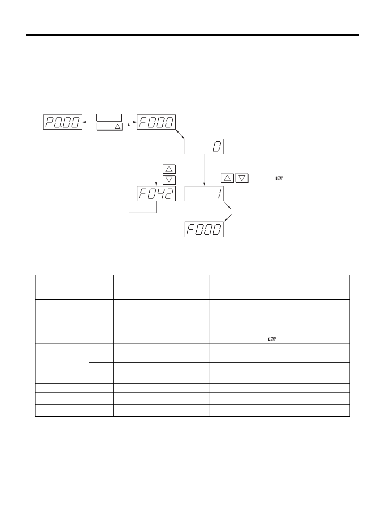
3.4.2 How to Set Control Functions
■ Various settings (instantaneous power interruption (IPI), remote operation, capacity control
setting, pressure setting, etc.)
Switches display from monitor mode to setting mode (F mode).
リセット
表示切替
Pressandhold
simultaneouslyforat
least3seconds.
Performsame
operationtoreturn.
1
Displays000
ChangeseachtimeFUNCTIONispressed.
th
itemofFmode.
Displayssettingcontents.
F000:(0:Setssingleunitoperation.)
Fordetails,seetheFmodetable.
1
2
Forward
Back
Toaltersettings,changethevalueswiththe
2
1
buttons.(page26)
F000:(1:Setsmultipleunitcontrol.)
PressENTERtoenterthesettings.
Back
Settings can be altered or entered into the memory from the digital monitor without opening the start panel.
Function
Multiple unit control setting
Instantaneous power interruption (IPI) restart setting
7 segment
display
Item Range
F000 Control setting 0 〜 110
F002
Instantaneous power interruption (IPI) setting
0〜1 1 00:ON、1:OFF
Instantaneous power inter-
F003
ruption (IPI) detection period
1〜511
setting"
Remote control switch
method
Remote operation shutdown recovery
0〜310
0〜1 1 00:Disable, 1:Enable
Remote operation setting
F005
F006 Remote operation method 0〜1 1 00:Pulse input, 1:Level input
F007
AUTO setting (*2) F011 AUTO operation enable 0〜1 1 00:Enable, 1:Disable
Capacity control F018 Control pressure selection 0〜210
Function setting
(optional)
F021 Pressure control mode 0〜210
Note:
※ Setting can be altered at any time other than this.
*1:When set to 1,” history is cleared. After clearing, the value is automatically reset to “0.”
*2:Only the V type is equipped with AUTO function. The AUTO function is available as an option for the Fixed speed type.
*3:Refer to the below chart about the Pressure setting.
Don’t change the setting of digital monitor besides the above parameter F (7 segment display: F
Precision/
unit
Initial value
***).
0: Single operation, 1: Multiple unit
control (communication supported)
When IPI is available, Instantaneous
power interruption is detected between
20ms and the setting detection period,
then the compressor restarts.
(
page 25)
0:Panel setting, 1:Local fi xed,
2:Remote fi xed,
3: Remote switch signal
0:Setting 1, 1:Setting 2,
2:External input
0:Built-in sensor, 1:External contact,
2:External input
25
3. OPERATING THE DSP [How to Use the Digital Monitor]
Function
Pressure
setting 1
※
(*3)
psi)
V type
】
125
【
MPa (110
】
0.86
【
0.75
Standard
type
V type
1.0 MPa (145 psi)
Standard
type
Shutdown history clear
Pressure
setting 2
※
(*3)
Pressure
setting 1
※
(*3)
Pressure
setting 2
※
(*3)
Pressure
setting 1
※
(*3)
Pressure
setting 2
※
(*3)
Pressure
setting 1
※
(*3)
Pressure
setting 2
※
(*3)
7 segment
display
F022
F023
F024
F025 (*2)
F031
F032
F033
F034 (*2)
F023
F024
F032
F033
F026
F027
F028
F029
F035
F036
F037
F038
F027
F028
F036
F037
F041 (*1)
Item Range
Control pressure setting 1
(control pressure)
Start pressure 1
(cut out pressure)
Recovery pressure 1
(cut in pressure)
P type recovery pressure 1
(restart pressure)
Control pressure setting 2
(control pressure)
Start pressure 2
(cut out pressure)
Recovery pressure 2
(cut in pressure)
P type recovery pressure 2
(restart pressure)
Start pressure 1
(cut out pressure)
Recovery pressure 1
(cut in pressure)
Start pressure 2
(cut out pressure)
Recovery pressure 2
(cut in pressure)
History Clear 0〜1 1 0 0 : Enter, 1 : History clear
0.5〜0.75 【0.86
(73〜110 【125】)
0.5〜0.77 【0.88
(73〜112 【128】)
0.5〜0.73 【0.84
(73〜106 【122】)
0.5〜0.73 【0.84
(73〜106 【122】)
0.5〜0.75 【0.86
(73〜110 【125】)
0.5〜0.77 【0.88
(73〜112 【128】)
0.5〜0.73 【0.84
(73〜106 【122】)
0.5〜0.73 【0.84
(73〜106 【122】)
0.5〜0.75 【0.86
(73〜110 【125】)
0.5〜0.65 【0.76
(73〜94 【110】)
0.5〜0.75 【0.86
(73〜110 【125】)
0.5〜0.65 【0.76
(73〜94 【110】)
0.5〜1.0
(73〜145)
0.5〜1.02
(73〜148)
0.5〜0.98
(73〜142)
0.5〜0.98
(73〜142)
0.5〜1.0
(73〜145)
0.5〜1.02
(73〜148)
0.5〜0.98
(73〜142)
0.5〜0.98
(73〜142)
0.5〜1.0
(73〜145)
0.5〜0.9
(73〜131)
0.5〜1.0
(73〜145)
0.5〜0.9
(73〜131)
Precision/
】
】
】
】
】
】
】
】
】
】
】
】
unit
0.01MPa
(1.5psi)
0.01MPa
(1.5psi)
0.01MPa
(1.5psi)
0.01MPa
(1.5psi)
0.01MPa
(1.5psi)
0.01MPa
(1.5psi)
0.01MPa
(1.5psi)
0.01MPa
(1.5psi)
0.01MPa
(1.5psi)
0.01MPa
(1.5psi)
0.01MPa
(1.5psi)
0.01MPa
(1.5psi)
0.01MPa
(1.5psi)
0.01MPa
(1.5psi)
0.01MP
(1.5psi)
0.01MPa
(1.5psi)
0.01MPa
(1.5psi)
0.01MPa
(1.5psi)
0.01MPa
(1.5psi)
0.01MPa
(1.5psi)
0.01MPa
(1.5psi)
0.01MPa
(1.5psi)
0.01MPa
(1.5psi)
0.01MPa
(1.5psi)
Initial value
0.75 【0.86
(110 【125】)
0.77 【0.88
(112 【128】)
0.72 【0.83
(104 【120】)
0.72 【0.83
(104 【120】)
0.75 【0.86
(110 【125】)
0.77 【0.88
(112 【128】)
0.72 【0.83
(104 【120】)
0.72 【0.83
(104 【120】)
0.75 【0.86
(110 【125】)
0.65 【0.76
0.75 【0.86
(110 【125】)
0.65 【0.76
a
(94 【110】)
(94 【110】)
1.0
(145)
1.02
(148)
0.97
(141)
0.97
(141)
1.0
(145)
1.02
(148)
0.97
(141)
0.97
(141)
1.0
(145)
0.9
(131)
1.0
(145)
0.9
(131)
】
】
】
】
Setting can be altered at any time.
※
】
】
】
】
】
】
Setting can be altered at any time.
※
】
】
Setting can be altered at any time.
※
Setting can be altered at any time.
※
●Pressure setting condition
Type Setting condition (Example of Pressure setting 1)
Standard type
V type
①Start pressure (F023) cannot be set below the value of Recovery pressure (F024) (F025) + 3 psi.
① Start pressure (F023) cannot be set below the value of Control pressure (F022) + 3 psi.
② Recovery pressure cannot be set above the value of Control pressure (F022).
Note 1. The higher value, in which value of Recovery pressure (F024) or (F025), becomes the standard type condition ①.
2. The setting condition is same in case of Pressure setting 2 (F031〜F034).
IMPORTANT
1. Pressure setting
V type: Set pressure differential of start pressure and recovery pressure to a minimum of 7 psi when using a standard receiv-
er. Set Pressure differential of start pressure and control pressure to a minimum of 3 psi.
Fixed speed type: Set pressure differential of start pressure and recovery pressure to a minimum of 15 psi.
2. Function for switching to pressure setting 2 by external pressure alteration input is optional.
26
3. OPERATING THE DSP [How to Use the Digital Monitor]
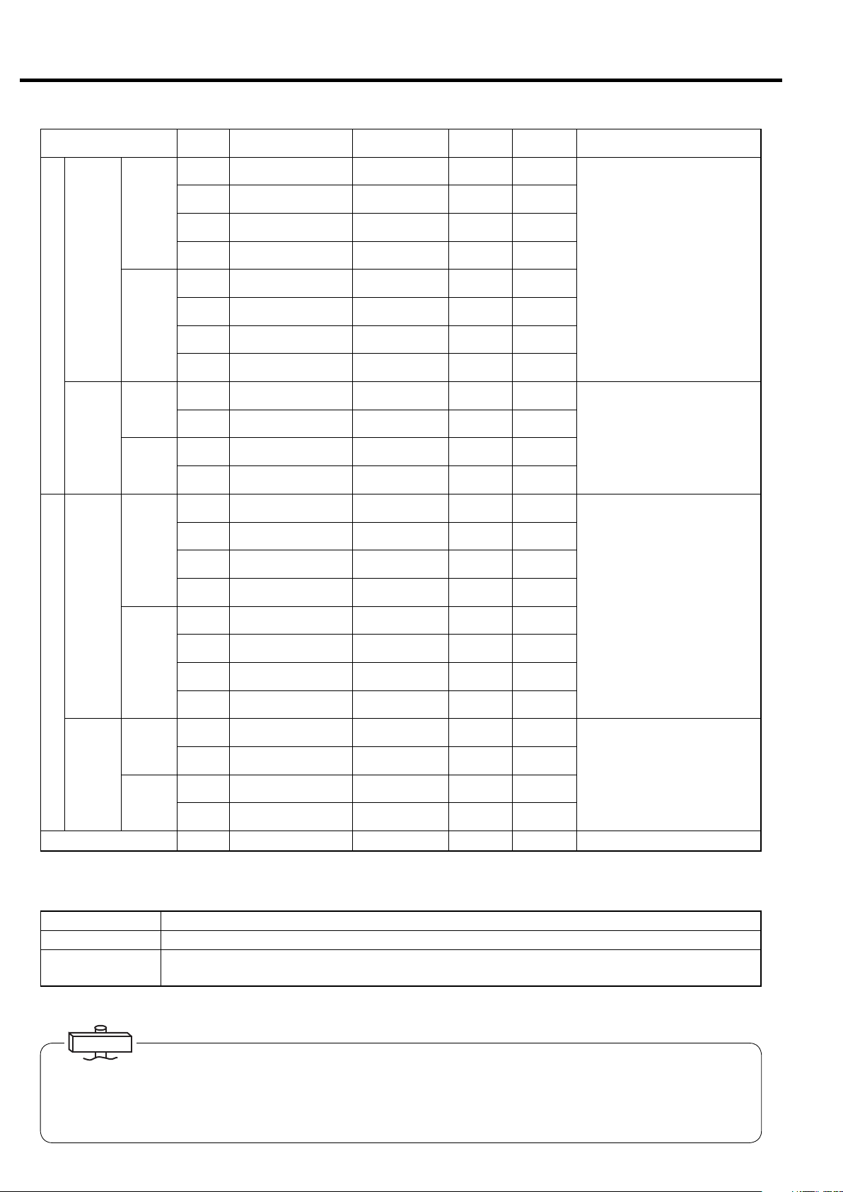
3.4.3 Alteration of Pressure Setting Values
Pressure
setting1
Pressbutton.
機能
Pressbutton.
記憶
1
Alter
values.
2
Use the following procedure to alter the pressure setting
values for the capacity control system.
① Switch from monitor mode to setting mode (F mode).
② Set PRESSURE SETTING 1 of F mode.
(For detailed contents of setting specifications, see
page 26.)
If using pressure setting 2, you must also set pres-
sure setting 2.
For operation method, be sure to refer to the various
settings, and after entering the setting values with the
STORE button, return to the monitor mode.
3.4.4 Capacity Control Mode Setting and
Confirmation
AUTOsetting
機能
Pressbutton.
Pressbutton.
記憶
SettoAUTOOFF.
(Initialvalue0)
1
Alter
values.
2
IMPORTANT
The AUTO function is available for the Fixed speed type
as an option.
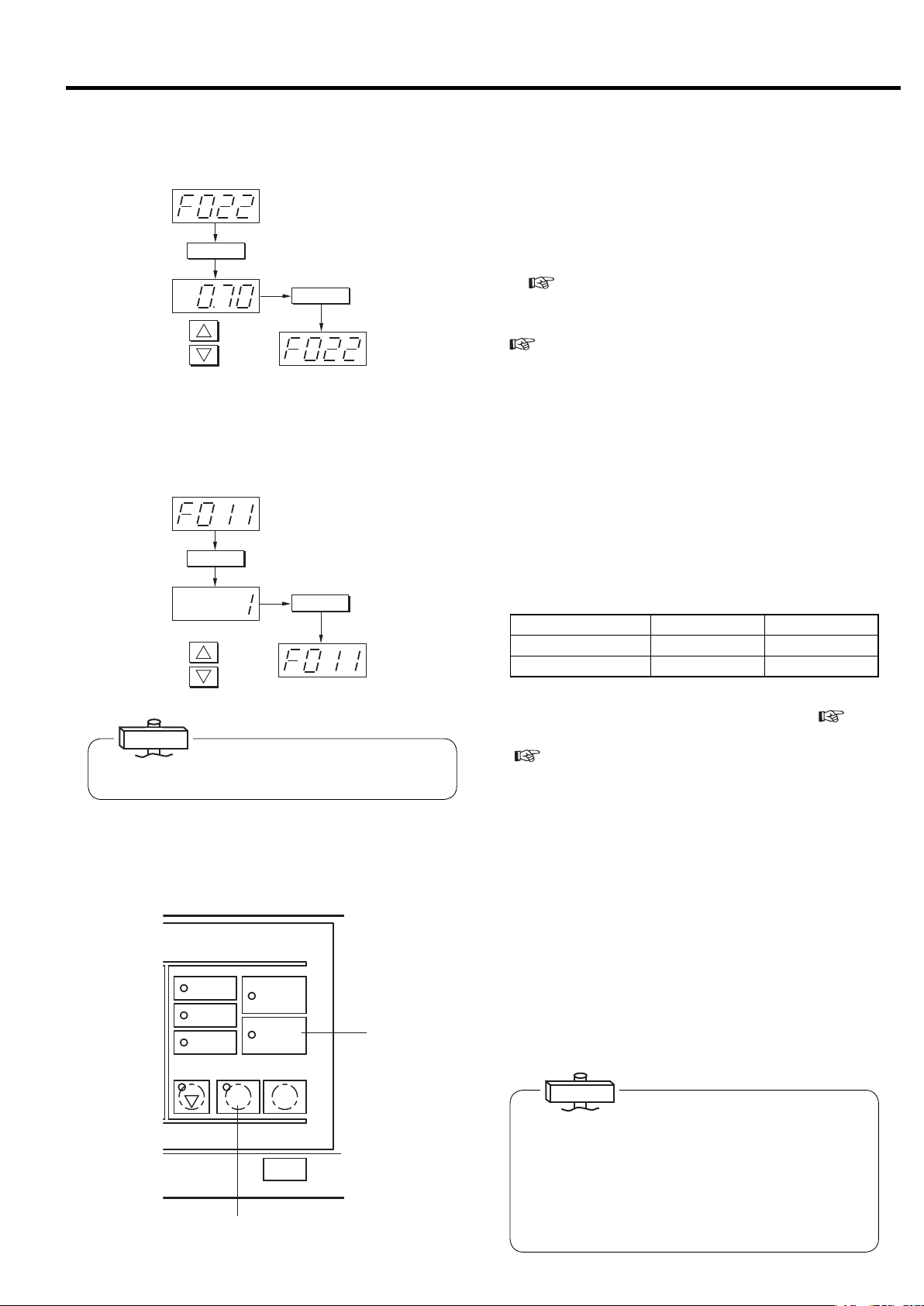
3.4.5 Restart for Instantaneous Power
Interruption
運転状況
RUNNINGMODE
遠方
REMOTE
負荷
LOAD
故障
SHUTDOWN
2
電源
POWER
起動待ち
AUTOSTART
運転 停止
START
STOP
UNLOAD STOP
②③
③
You can switch the capacity control mode by the following method according to the application. The V type is a
automatic stop type, but can also be changed to control
mode that does not stop automatically (AUTO OFF).
Capacity control mode setting can be changed by switching the digital monitor from monitor mode to setting
mode (F mode) while the compressor is not running and
setting to “0: Enable” or “1: Disable” by altering the
AUTO setting (F011) of F mode.
Capacity control mode AUTO ON AUTO OFF
F011 0 : Enable 1 : Disable
Digital monitor display
0.AXX0.UXX
After altering, confirm the capacity control mode by display of various settings on the digital monitor (
page
23).
For capacity control operation and details, see pages
(
29 and 62 - 63. Pressure for control can also be
switched by F018 (pressure setting 1 / pressure
setting 2).
The DSP has restart function for instantaneous power
interruption (IPI). When the DSP detects IPI, blinking
the AUTO START Light, the DSP restarts automatically.
① This function is abailable for IPI between 20ms and 5
seconds.
② The DSP stops automatically after detecting IPI and
the OPERATION Light is turned off.
③ After recovering the voltage, the AUTO START Light
blinks and the OPERATION Light turns on.
④ The DSP restarts automatically.
IMPORTANT
(1) Instantaneous power interruption (IPI) means that the
power voltage drops to zero (0) instantaneously.
(2) For the IPI time of less than 20 ms, the DSP air com-
pressor will continue to run.
(3) For the IPI time of more than the setting, the DSP judg-
es it as a power failure; the DSP stops but does not
restart automatically. Press the START button to restart
the DSP air compressor.
27
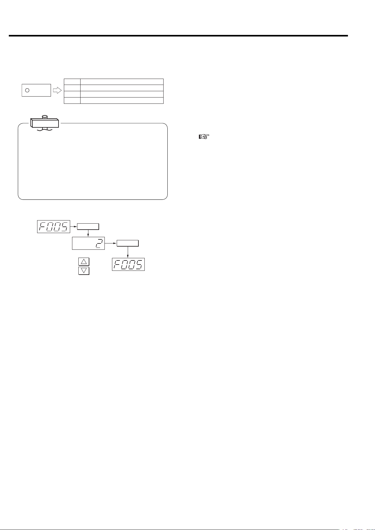
3. OPERATING THE DSP [How to Use the Digital Monitor]
3.4.6 Remote Operation Setting
(1) Remote setting by instrument panel
On
(2) Remote setting fixed
遠 方
REMOTE
IMPORTANT
● In the case of multiple unit control specifications, when
multiple unit control is set, it automatically changes to
the remote setting. The REMOTE light flashes at this
time.
● Remote operation method alteration in the setting
mode can only be entered when the compressor is not
operating.
● The compressor STOP button can also be used to
stop operation when operating in the remote mode.
Remote
operation
switch
method
On
(3) Remote setting by external operation button
Flashing
Local setting
Off
機能
Pressbutton.
(Initialvalue1)
1
Alter
values.
2
Pressbutton.
記憶
Settoremotefixed.
Operation mode is basically switched by panel operation.
The remote operation mode can also be set by methods
(2) and (3).
① Turn off the main power supply.
② Remove the front cover and remove the start panel
cover.
③ Connect the wiring of the remote control panel and
the compressor control panel.
(
See the wiring diagrams on pages 51 - 56.)
④ Mount the start panel cover and the front cover.
⑤ Turn on the main power supply.
[1] To “set the operation buttons of the instrument
panel to remote operation mode”
① Press the REMOTE button.
② The REMOTE light lights to indicate that operation of
the instrument panel buttons is set to the remote
operation mode.
③ To return to local operation mode, press the
REMOTE button again. The REMOTE light then
goes off to indicate that operation has been switched
to the local operation mode.
[2] To “fix remote operation to remote operation
mode”
① Switch from the monitor mode to the setting mode (F
mode).
② Change the remote operation switch method for
remote operation setting (F005) from “0: Panel set-
ting” to “2: Remote fixed.”
③ The REMOTE light lights to indicate that the remote
operation mode has been set.
[3] To “set to remote operation by operation button
provided externally”
(Consult with your dealer or the Hitachi Service
Station.)
① Wire the external remote setting buttons.
② Switch from the monitor mode to the setting mode (F
mode).
③ Change the remote operation switch method for
remote operation setting (F005) from “0: Panel set-
ting” to “3: Remote switch signal.”
28
④ Set the external remote setting button to “ON.”
⑤ The REMOTE light flashes to indicate that the opera-
tion mode has been switched to remote operation by
external buttons.

3. OPERATING THE DSP [How to Use the Digital Monitor]
3.4.7 Pressure Setting Switch Function
According to alteration of the pressure setting value of
section 3.4.1, by setting start pressure 2 (value of F032)
and recovery pressure 2 (value of F033), the control
setting can be easily switched by external button operation in accordance with usage time on the load side.
During ordinary control, the LOAD light is lit when loading and goes off when unloading. With pressure setting
2, however, the light flashes when loading and goes off
when unloading.
For details, refer to page 24. (The ECOMODE however
cannot be used with pressure setting 2.)
Energy Saving Effect
Start
pressure 1
Start
pressure2
Recovery
pressure 1
Recovery
pressure2
Line pressure
Load light
External pressure setting switch
Load Unload
Ordinary (on range)
※Start pressure = Cutout pressure
※Recovery pressure = Cutin pressure
Pressure setting 2 selection (flash range)
ONOFF
Time
3.4.8 Capacity Control Flow when ECOMODE (Energy Saving Mode) is Set
(ECOMODE is set to off when shipped from the factory, but may be set according to your needs.)
Execute capacity control in accordance with the following
time charts.
(1) ECOMODE (Energy Saving Mode) setting
When you set to ECOMODE by load/unload type con-
trol, if the cycle time for load → unload exceeds 30
seconds, the start pressure setting is automatically
lowered until it reaches recovery pressure + 0.05
MPa to conserve energy.
If 30 seconds is exceeded, the DISPLAY SWITCH /
WIDE MODE light flashes; if 30 seconds is not
exceeded, the DISPLAY SWITCH / WIDE MODE
light lights steadily, and control is executed by pressure setting value of ordinary load/unload type control.
When using ECOMODE (Energy Conservation
Mode), “ECO” is displayed on the monitor screen.
page 14)
(
運転管理
RUNNING CONTROL
警 報
ALARM
機 能
リセット
RESET
FUNC
遠 方
REMOTE
記 憶
STR
Energy Saving Effect
Start pressure
(Unload start pressure)
表示切替/
ワイド モー ド
SELECT/WIDE
1
表示切替/
ワ イドモ ード
SELECT / WIDE
ON : Light flashes.
OFF : Light goes off.
表示 切替/ワイドモード
Set by button
1
Start pressure
is automatically
reduced.
(2) Precautions when using ECOMODE (Energy
Saving Mode)
Enabling ECOMODE (Energy Conservation Mode)
requires an air tank that is one turn larger that the air
tank recommended for load/unload type control.
For information concerning the air tank, see
(
page 41.)
This function is used for load/unload type control, and
operates only for the ordinary pressure setting.
Recovery pressure
(Load recovery pressure)
Line pressure
Load Unload
Time
※Start pressure = Cutout pressure
※Recovery pressure = Cutin pressure
Factory set upper/lower limit pressure differential
ECOMODE differential pressure
: 15 psi
: 7 psi
Start pressure is automatically reduced to 1 cycle per 30 seconds.
29

3. OPERATING THE DSP [Daily Operation]
3.5 Daily Operation
CAUTION
● When using the DSP air compressor, do not raise the discharge pressure excessively. Operating the
DSP air compressor over the rated pressure can result in main motor overload, shutdown of the
airend and/or damage of parts.
● If the safety relief valve has blown or a protective device has shutdown the DSP air compressor,
investigate the cause of and take corrective action. If there any questions or comments in taking these
actions, please contact the local Hitachi distributor.
3.5.1 Preparing the DSP Air Compressor
②
③
運転管理
RUNNING CONTROL
警 報
ALARM
機 能
リセット
RESET
FUNC
遠 方
REMOTE
記 憶
STR
表示切替/
ワイドモード
SELECT/WIDE
1
運転状況
RUNNING MODE
遠 方
REMOTE
負 荷
LOAD
故 障
SHUTDOWN
運 転
START
2
電 源
POWER
起動待ち
AUTO START
停 止
STOP
UNLOAD STOP
① Turn on the main power supply.
– STOP lamp on the add-on reactor starer panel glows for
reactor starting model.
– Power lamp glows for −△ starting model.
② Check the POWER light and LCD monitor display.
– Is the light lit ?
– Is the monitor screen displayed on the LCD monitor?
③ Check the level of lubricating oil.
– Is the oil level near the red line ?
④ Set the water drainage cock valve of the cooling water
piping and the water drainage cock on the back of the
compressor to “fully closed.”
⑤ Allow cooling water to pass through.
IMPORTANT
Make sure the oil level of the lubricating oil is between the
red lines while the compressor is running. Because lubricating oil is circulated through the cooler and the piping
while the compressor is running, the position when the
compressor is running and when it is off differs, and is
higher when the compressor is not running.
3.5.2 Starting the DSP Air Compressor
②
30
①
警 報
DIS.PRESS:110psi
INTSTG.P:22psi
OILPRESS:22psi
CLTPRESS:***psi
③④
運転管理
RUNNING CONTROL
ALARM
機 能
リセット
RESET
FUNC
表示切替/
遠 方
ワイドモード
REMOTE
SELECT/WIDE
記 憶
STR
1
運転状況
RUNNING MODE
遠 方
REMOTE
負 荷
LOAD
故 障
SHUTDOWN
運 転
START
2
電 源
POWER
起動待ち
AUTO START
停 止
STOP
UNLOAD STOP
① Open the discharge side valve.
② Start operation by pressing the START button.
– START lamp on the add-on reactor starter panel glows for
reactor starting model.
– START lamp glows for −△ starting model.
③ Check the pressure after the compressor starts up.
– The compressor stops running if the oil pressure does not
rise to at least 12 psi.
– The compressor switches to full load operation within 15
seconds for the
for the reactor starting model.
−△ starting model and within 8 seconds
④ Make sure the discharge pressure rises gradually.
– Make sure the maximum pressure does not exceed the spec-
ified discharge pressure.

3.5.3 During Operating the DSP Air Compressor
運転管理
自動
AUTO
モニタ
MONITOR
メニュー
MENU
+/−
UP/
DOWN
設定
MONITOR
㻞㻜㻜㻥䠋㻜㻠䠋㻝㻟 㻝㻥䠖㻜㻞
㻼㻾㻱㻿㻿㼁㻾㻱
㻵 㻺 㼀㻿 㼀 㻳䠊㻼 䠖 㻌 㻌 㻞 㻥 㼜 㼟 㼕
㻻 㻵 㻸 㻌 㻼㻾㻱㻿 䠖 㻌 㻌 㻝 㻡㼜 㼟 㼕
㻯㻸 㼀䠊㻼㻾㻱 㻿䠖 㻖䠊 㻖 㻖 㼜 㼟 㼕
㼀㻱㻹㻼㻱㻾㻭㼀㼁㻾㻱
㻰㻵 㻿䠊㼀㻱㻹㻼㻝䠖 㻟㻞㻜䉣
㻰 㻵 㻿䠊 㼀㻱㻹㻼 㻞 䠖 㻟
㻻 㻵 㻸 㻌 㼀 㻱㻹㻼 䠖 㻟㻢 䉣
㻯㻸㼀䠊㼀㻱㻹㻼䠖 㻖㻖㻖䉣
㻞㻺㻰 㻌 㻿㼁㻯 㼀䠊㼀䠊 䠖 㻜 㻤 䉣
㻹㻭 㻵 㻺㼀 㻱㻺 㻭㻺㻯 㻱
㻴㻾䠊㼀㻻㻌㻹㻭㻵 㻺㼀䠖 㻜㻜㻜㻜䡄
㻺㻱㼄㼀㻌 㻹㻭 㻵㻺㼀䠖 㻖㻖㻖㻖
SET
RUNNINGCONTROL
警報
ALARM
機能
FUNC
リセット
RESET
遠方
記憶
STR
[×10h]
表示切替/
ワイド モード
SELECT/WIDE
1
㻝
㻝
運転状況
RUNNINGMODE
遠方
REMOTE
負荷
LOAD
故障
SHUTDOWN
2
㻟㻤䉣
電源
POWER
起動待ち
AUTOSTART
運転 停止
STARTREMOTE
STOP
UNLOAD STOP
3. OPERATING THE DSP [Daily Operation]
① Check the LCD for operating pressures and tempera-
tures, and verify that:
– Discharge air pressure, interstage air pressure, oil pressure,
discharge air temperature, 2nd-stage suction air temperature,
and oil temperature stay within a normal range; see page 45
② Make sure air containing drain from the inter cooler
drain discharge port and after cooler drain discharge
port is intermittently discharged.
3.5.4 Stopping the DSP Air Compressor
④
③
RUNNING CONTROL
警 報
ALARM
機 能
DIS.PRESS:000psi
NTSTG.P:000psi
OILPRESS:000psi
CLTPRESS:***psi
②
運転管理
リセット
RESET
FUNC
遠 方
REMOTE
記 憶
STR
①
表示切替/
ワイドモード
SELECT/WIDE
1
運転状況
RUNNING MODE
遠 方
REMOTE
負 荷
LOAD
故 障
SHUTDOWN
運 転
START
2
電 源
POWER
起動待ち
AUTO START
停 止
STOP
UNLOAD STOP
① Press the UNLOAD STOP button. The compressor
then unloads for 5 minutes and then stops running.
(In the case of an emergency, press the STOP but-
ton.)
– STOP lamp on the add-on reactor starter panel glows for
reactor model.
② Check the LCD for pressures, and verify that:
– Oil pressure, interstage air pressure, 0 psi (or 1.5 psi depend-
ing on your operating conditions)
.
③ Check the condensate drain discharge from the con-
trol line filter by checking the sight glass on the control line filter.
④Close the discharge stop valve.
⑤ Stop the cooling water.
Open the valve for draining water in the cooling water
piping and drain the cooling water.
To avoid damaging the casing and cooler, be careful
not to allow freezing during the winter.
31

3. OPERATING THE DSP [Oil Mist Remover Daily Operation, Adjusting the DSP]
3.6 Oil Mist Remover Daily Operation
3.6.1 When Starting
8
φ
Pressure Gauge
51 to 58 psi
Make sure that the pressure
gauge reads as follows:
Make sure that the
condensate is not
Make sure that the vacuum
indicator does not show a
red mark.
Condensate Drain Cock
3.6.2 When Stopping
collected in the
filter bowl.
If the condensate is
collected, push up
the cock to drain
the condensate.
② The first steps to resolve the lower suction vacuum
pressure are as following.
A) Clean or replace the air intake filter.
B) Clean the suction throttle valve’s valve plate.
Note; If the unloaded interstage pressure drops as
low as -0.08MPa (-12 psi), discharge air temperature will gradually increased.
③ If the DSP air compressor cannot be shutdown to
clean these parts, turn the adjusting bolt (the suction
bypass valve) counterclockwise to open. This will
allow the air intake and increase the discharge air
pressure to be geater than -0.08 MPa (-12 psi) when
running unloaded.
④ Replace the consumable parts in the air intake filter
and suction throttle valve with new consumable parts
in accordance with the appropriate maintenance
schedule.
For the detail refer to the section 9,
Maintenance the DSP.
IMPORTANT
If the discharge pressure becomes lower than -0.08 MPa (-12
psi) during unload operation, shaft sealing function decrease.
3.7.2 Regulating the Oil Pressure
① Make sure that the vacuum indicator shows a red
mark.
② Verify that the pressure gauge reads 0 (zero).
3.7 Adjusting the DSP
3.7.1 While Operating the DSP Air Compressor
②④
Air Intake Filter
① When dust particles accumulate on the valve plate of
the suction throttle valve, the suction vacuum pressure may drop and eventually causing the discharge
air temperature to rise.
①④
Suction Throttle
Valve
Seal Washer
Locknut
③
Adjusting Bolt
(Suction Bypass Valve)
Usually keep the bolt
tightened, but not excessively.
Relief Valve
① Use the relief valve to regulate the oil pressure. To
regulate the oil pressure, open the relief valve cap,
loosen the lock nut, and turn the regulating bolt to
keep the oil pressure at the specified 0.12 to 0.16 MPa
(17 to 23 psi).
・0.12 to 0.16 (17 to 23 psi) when the ambient temper-
ature is 20 degree C or higher.
・0.14 to 0.18 (20 to 26 psi) when the ambient temper-
ature is 20 degree C or lower.
(for V type, adjust at the maximum operating frequency.)
② Turn the regulating bolt clockwise to increase the oil
pressure and vice versa.
③ Tighten the locknut and replace the cap.
IMPORTANT
If the oil pressure is reduced to 0.08 MPa (12 psi) or lower, the oil
pressure sensor will detect it and shut down the DSP air compressor.
32

4. TROUBLESHOOTING
CAUTION
If an alarming trouble or a shutdown trouble has happened, investigate the cause and take a corrective
remedy before restarting.
If you have anything unclear or any question, please contact the local Hitachi distributor.
4.1 Protective Devices
The DSP is provided with the protective devices as listed below. Shutdown troubles and alarming troubles detected by
these protective devices are indicated on the liquid crystal display (LCD). Referring to the LCD indications, investigate the
cause of a shutdown or alarming trouble.
■ When Connecting the power
Heading
PROBREM
LCD Indication
Trouble Description
Reversal phase connection
Phase-lacking connection
Short period Power Interruption
Instantaneous Power Interruption
What and
How to Detect
Detected for 3
seconds after
connecting the power
Black out for 1 to 5 seconds
Black out for less than 1 seconds
SHUTDOWN
MODE Light
Blinks
in red
−
Detector
CPU Yes Change 2 of 3 wires of the power cord.
CPU Yes
CPU No
CPU No
Shutdown
What Actions to Take
Reconnect the power cord tightly, check the
power supply, and take a corrective remedy.
See page for Power Interruption detection
See page for Power Interruption detection
How to
Reset
Press RESET
button.
Press RESET
button.
−
History
Code
01
02
03
04
■ During Operation
LCD Indication
Heading
SHUTDOWN
FAILURE
INVSTOP
Trouble Description
Discharge air temperature (1)
Discharge air temperature (2)
Interstage pressure
2nd-stage suction air
temperature
Oil temperature
Oil pressure
[Fixed speed]
Oil pressure
(OIL-LOW PRESS)
Overloading
(main motor)
Overloading
(ancillary motor)
Answer error of 52
Answer error of 42
Inverter tripping or main
motor overloading with
automatic retrials.
What and
How to Detect
The temperature detected
at 1st stage rises above
the below settings.
Warning seeting+5℃(+41℉)
The temperature detected
at 1st stage rises above
the below settings.
Warning seeting+5℃(+41℉)
0.27MPa (39psi) or higher
70℃ (158℉) or higher
(after the intercooler)
70℃ (158℉) or higher
0.08MPa (12psi) or lower
Oil pressure descends
under below settings.
Freg. 45Hz
or higher
Freg. less
than 45Hz
Detected during operation
Detected during operation
Detected during
running.
Detected after shifting
to △ running.
Failure signal from
inverter
0.08MPa
(12psi)
0.04MPa
(6psi)
SHUTDOWN
MODE Light
Blinks
Blinks
Blinks
Blinks
Blinks
Blinks
Blinks
Blinks
Blinks
Blinks
Blinks
Blinks
Detector
Thermistor Yes See page 35
in red
Thermistor Yes See page 35
in red
Pressure sensor
in red
Thermistor Yes See page 35
in red
Thermistor Yes See page 35
in red
Pressure sensor
in red
Pressure sensor
in red
Thermal relay
in red
Thermal relay
in red
in red
in red
in red
CPU
CPU
CPU
Shutdown
Failure
stop after
repetition
of retrials.
What Actions to Take
Yes See page 35
Yes See page 35
Yes See page 35
Yes See page 35
Yes See page 35
Yes See page 35
Yes See page 35
See page 35
How to
Reset
Press RESET
button.
Press RESET
button.
Press RESET
button.
Press RESET
button.
Press RESET
button.
Press RESET
button.
Press RESET
button.
Press RESET
button.
Press RESET
button.
Press RESET
button.
Press RESET
button.
Press RESET
button.
History
Code
55
56
52
5B
58
5C
5C
17
53
51
16
44
33

4. TROUBLESHOOTING [Protective Devices]
■ Others
LCD Indication
Heading
ALARM
PROBLEM
FAILURE
Trouble Description
Clogging of air
intake fi lter
Discharge air
temperature (1)
Discharge air
temperature (2)
2nd-stage suction air
temperature
Oil temperature
Oil pressure
[Fixed speed]
L. COUNT OVER
( Load/unload cycle
count)
Battery out Battery voltage low
Error of a scheduling
operation
Error of a multipleunit operation
Error of RS−485C
port
Error of RS−485
port
PCB error
CT error Disconnected
Pressure sensor
(disconnection 1)
Pressure sensor
(disconnection 2)
Pressure sensor
(disconnection 4)
Temperature sensor
(disconnection 2)
Temperature sensor
(disconnection 3)
Temperature sensor
(disconnection 4)
Temperature sensor
(disconnection 5)
What and
How to Detect
Pressure differential of
−4.98kPa (0.7psi) or more
The temperature detected
at 1st stage rises above
the below settings.
NOTE 5)
The temperature detected
at 2nd stage rises above
the below settings.
NOTE 5)
63℃ (145℉) or higher
(after the intercooler)
63℃ (145℉) or higher
0.10MPa (15psi) or
lower
1 million times
Start/stop time not set
yet
Setting error
Setting error
Setting error
(ROM1) (RAM1)
MAIN Memory failed
(ROM2) (RAM2)
LCD Memory failed
PS1 disconnected (sensor
for interstage pressure)
PS2 disconnected (sensor
for discharge air pressure)
PS4 disconnected (sensor
for Oil pressure)
TH2 disconnected (thermistor
for interstage temperature)
TH3 disconnected (thermistor for
2nd-stage discharge temperature)
TH4 disconnected (thermistor for
1st-stage discharge temperature)
TH5 disconnected
(thermistor for oil temperature)
NOTES:
1. Both the DSP for a 400 V class power supply and the DSP with a control circuit of 100 volt employ a reversal phase relay.
2.
Both the DSP for a 400 V class power supply and the DSP with a control circuit of 100 volt indicate a phase-lacking connection as a reversal phase.
3. Battery Replacement:
Replace the battery with a new one every 6 years. When replacing, disconnect the power and complete the replacement work within 15 minutes.
4. If a Thermistor is disconnected, an override operation is not allowed. Contact your distributor immediately.
5. Refer the normal indication value of devices in the coution decal on the front panel of the unit for the setting values of waring.
SHUTDOWN
in green
in green
in green
in green
in green
in green
in green
in green
in green
in green
in green
in green
Detector
MODE Light
Pressure
Blinks
differential
sensor
Blinks
Thermistor No See page 35
Blinks
Thermistor No See page 35
Blinks
Thermistor No See page 35
Blinks
Thermistor No See page 35
Blinks
Pressure sensor
Blinks
Blinks
Blinks
Blinks
Blinks
Blinks
Blinks
in red
Blinks
in red
Blinks
in red
Blinks
in red
Blinks
in red
Blinks
in red
Blinks
in red
Blinks
in red
Blinks
in red
Blinks
in red
CPU No
CPU No
CPU No Check the operation setting.
CPU No
Thermistor Yes
Pressure sensor
CPU Yes
CPU Yes
CPU Yes
CPU Yes
CPU Yes
CPU Yes
CPU Yes
CPU Yes
CPU Yes
CPU Yes
Shutdown
Yes See page 35
Yes
What Actions to Take
No See page 73
Replace suction throttle valve consumable parts and Blow off solenoid valves
Disconnect the power, and replace the
battery with a new one.
Check the wire and the operation
setting.
Check the wire and the operation
setting.
Check the wire and the operation
setting.
Disconnect and reconnect the power. If the
problem is reproduced, change the PCB.
Disconnect and reconnect the power. If the
problem is reproduced, change the PCB.
Disconnect the power and check the
CT sensor wire for tightness.
Disconnect the power and check the
pressure sensor wire for tightness.
Disconnect the power and check the
thermistor sensor wire for tightness.
How to
Reset
Press RESET
button.
Automatically
reset.
Automatically
reset.
Automatically
reset.
Automatically
reset.
Press RESET
button.
Hold the REMOTE
Button and SELECT/
WIDE Button for
at lease 7 seconds
Press RESET
button.
Press RESET
button.
Press RESET
button.
Press RESET
button.
Press RESET
button.
Press RESET
button.
Press RESET
button.
Press RESET
button.
Press RESET
button.
Press RESET
button.
Press RESET
button.
Press RESET
button.
Press RESET
button.
Press RESET
button.
Press RESET
button.
History
Code
21
25
26
2B
26
2C
59
64
62
5B
63 65
〜68
63 65
〜68
43
47, 48
41, 42
46
E10
33
34
39
32
35
36
37
34

4. TROUBLESHOOTING [Troubleshooting the Air Compressor]
4.2 Troubleshooting the Air Compressor
Most likely problems, causes, and remedies are described below.
Causes LCD Indication Causes Corrective Remedies
The DSP motor
does not start.
<P R O B L E M>
CONNECTION ERR: REV
RES
Press
<P R O B L E M>
CONNECTION ERR: OPEN
Press
after CHK.
RES
after CHK.
1. Power supply switch - Off
2. Power - Failed
3. Power cord - In a reversal phase
connection
4. Power cord - In a phase-lacking
connection
1. Check the main breaker.
2. Check the power supply.
3. Change 2 of 3 wires of the power
cord.
4. Reconnect the power cord tightly and
check the power supply.
NOTE: Phase-lacking is detectable only
when connecting the power.
Shutdown –
1st-stage discharge air temperature and/ or
pressure too high
Shutdown –
2nd-stage discharge air temperature too high
Shutdown –
2nd-stage suction
air temperature
too high
Shutdown –
Oil temperature
too high
Shutdown –
Oil pressure too
low
<A L A R M>
DIS. TEMP.1:
RES
Press
<S H U T D O W N>
HIGH DIS. TEMP:
Press
<A L A R M>
DIS. TEMP.2:
Press
<S H U T D O W N>
2ND SUCT. TEMP:
Press
<S H U T D O W N>
OIL : HIGH TEMP
Press
<S H U T D O W N>
OIL : LOW TEMP
Press
after CHK.
RES
after CHK.
RES
after CHK.
RES
after CHK.
RES
after CHK.
RES
after CHK.
1. 2nd-stage AIR END air intake effi ciency - Lowered
2. Air intake fi lter - Dirty
3. Temperature of Suction Air-High
1. Check valve – Compressed air
leaked (from the aftercooler to the
air end when the DSP unloads)
2. Suction throttle valve - Dirty
1. Cooling water pump – Failed, or
Cooling water pressure – Fluctuating
2. Intercooler – Dirty
1. Oil cooler – Dirty
2. Room temperature – High
3. Oil temperature control valve –
Failed
1. Oil strainer and/or oil fi lter – Dirty
2. Oil level – Low
1. Contact your Hitachi distributor.
2. Clean the air intake fi lter.
3. Lower the suction air temperature.
1. Replace the check valve.
2. Clean the Suction throttle valve.
Note: For information about the Suction
bypass valve, see page 29.
1. Check the cooling water system.
2. Clean the intercooler
1. Check the oil cooler.
2. Reduce the room temperature.
3. Check the oil temperature control
valve.
1. Clean the oil strainer
2. Replace the oil fi lter.
3. Add the oil.
Shutdown –
Main motor and/
or ancillary motor
overloading
Shutdown
–
Inverter tripping/
restarting
<S H U T D O W N>
OVERLOAD : MAIN
RES
Press
<S H U T D O W N>
OVERLOAD : SUB
Press
<F A I L U R E>
SYSTEM RETRY :
after CHK.
RES
after CHK.
1. Power supply voltage – Low
2. Discharge air pressure – Too high
1. Power supply voltage – Low
2. Cooling fan motor – Failed
1.
Power supply voltage – Low or in unbalance
2. Discharge air pressure – Too high
3. Main motor – Overloading
NOTE:‘ INVERTER RESTART’ means that the DSP
shutdowns when the inverter repeats a
restarting action within 1 minute.
1. Rectify the power supply voltage.
2. Check the suction throttle valve
3. Check the capacity control system.
1. Rectify the power supply voltage.
2. Check the cooling fan motor.
(Measure insulation resistance etc.)
1. Rectify the power supply voltage.
2. Check the capacity control system.
3. Measure insulation resistance etc. or
check the main motor.
35

4. TROUBLESHOOTING [Troubleshooting the Oil Mist Remover]
4.3 Troubleshooting the Oil Mist Remover
① The vacuum indicator shows a red mark (Gear case has a positive internal pressure)
The pressure gauges reads zero (0) MPa (psi). Check the solenoid valve for operation.
No
Pressure setting of the regulator is lower ?
No
Pressure of a control air is lower than 0.39 MPa (56 psi) ?
No
The gear case or gear case vent pipe has a leak
(for example, the oil fi lling port plug on the gear case is not tight).
No
Element may be dirty.
Inspect the element and replace if necessary.
② The safety relief valve has opened and oil mists are vented (the gear case internal pressure has risen).
See the NOTE below.
Yes
Yes
Yes
Yes
Reset the regulator to a proper pressure.
Clean the fi lter.
Maintain the pressure of a control air at 0.39 MPa (56 psi) or more.
・ Tighten every screw and plug to remove all leaks.
・ Make sure that the safety relief valve is closed.
The safety relief valve is dirty or stuck open by a foreign
object.
No
Go to the procedure ①. The vacuum indicator shows a
red mark. (Gear case has a positive internal pressure.)
NOTE:
The safety relief valve opens immediately when starting the DSP (the control air pressure is still low) or when the DSP has
stopped. This is a normal occurrence.
Yes
Disassemble and clean the safety relief valve.
Replace if necessary.
③ Oil is vented through the ejector’s compressed air outlet (the separated oil is not being recovered).
Accumulated oil is visible in the tube between the element housing and the fl oat trap.
No
Upper or lower packing is not seated properly on the
element ?
No
Control air contains oil ? Check the control air for oil contents.
No
Element may be dirty.
Inspect the element and replace if necessary.
Yes
Yes
Yes
Clean the nozzle of the fl oat trap.
Reinstall the element, seating the packing properly for a
maximum sealing performance.
④ Oil pressure is low (oil pump may be inhaling air).
Has the air compressor developed an alarm or shutdown
trouble (i.e. oil fi lter dirty, oil pressure reduced due to oil
leaking, oil pump failed, safety relief valve failed, etc.)?
No
The nozzle of the fl oat trap is clogged (for example, a
large quantity of air is inhaled through the oil recovery
pipe to the oil pump inlet)?
NOTE:
The oil mist remover makes the gear case internal pressure negative during operation, reducing the pressure by 0.005 to 0.01
MPa (0.7 to 1.5 psi). This is not unusual; reset the oil pressure on the safety relief valve.
Yes
Yes
Readjust or repair as required.
Clean the nozzle of the fl oat trap. Disassemble the fl oat
trap and clean.
36

5. INSTALLING AND PIPING THE DSP
5.1 Unpacking the DSP Air Compressor
■ After unpacking the crate, verify that the inside DSP is what you have ordered, by referring to page 81 through 82
“STANDARD SPECIFICATIONS and also by checking the model nameplate.
■ Verify that the DSP is not damaged or deformed in transportation.
Model Nameplate
Motor Output (kW)
Model
Frequency (Hz)
Standard Accessories
Foundation Bracket 4 pieces
Foundation Bolt/Nut (M24) 4 pieces
Bolt (M24) for Foundation Bracket 4 pieces
Fork Slot Cover 4 pieces
Bolt (M6) for Fork Slot Cover 8 pieces
R-NPT Nipple (1/4B) 2 pieces
R-NPT Nipple (3/8B) 2 pieces
R-NPT Nipple (1/2B) 2 pieces
R-NPT Nipple (3/4B) 3 pieces
Gasket 1 pieces
Handle 1 pieces
Motorized Isolation Valve(※) 1 piece
Motorized Water Isolation Valve(※) 1 piece
Item ※-marked shall be supplied only for
5.2 Conveying the DSP Air Compressor
■ With a Forklift ■With a Shop Crane
Pad
Use a pad to protect
the DSP enclosure
panels.
Keep the distance of
1500 mm (60 inches)
or more.
Use the strong wires.
Adjust the wire length to
keep the DSP’s balance
when hoisting it.
Model Total Mass
DSP-132WN
DSP-145WN
DSP-160WN
DSP-200WN
DSP-240WN
3,800 kg
(8,378 lb)
4,800 kg
(10,582 lb)
Model Total Mass (kg)
DSP-160VWN
DSP-240VWN
4,000 kg
(8,819 lb)
5,100 kg
(11,244 lb)
Use the adhesive tapes
to prevent the front door
from detached during
conveyance.
Use a pad to protect the
DSP enclosure panels.
Use the attached
tie frame.
■ After installing the DSP, plug the fork slots with the fork
slot covers.
Common Base
Fork Slot Cover
Bolt (M6×15)
37

5. INSTALLING AND PIPING THE DSP [Installing the DSP Air Compressor]
5.3 Installing the DSP Air Compressor
WARNING
1. Keep flammable solvents or any other hazardous chemicals away from the DSP. Such chemicals may be
sucked by the air end, compressed, and exploded.
2. Do not use fire near the DSP; otherwise the sparks may enter the air end and burn it internally.
■ Install the DSP in a bright, wide, and airy room as follows:
Ventilating Fan
If you install the DSP in a
small room, provide a
ventilating fan to keep the
room temperature at 40℃
(104℉ ) or lower.
Piping and
Maintenance Space
Keep a space of 1.0 m (39
inches) or more to connect
a plant airline pipe and
ease the maintenance
servicing.
Plug the fork slots with
the fork slot covers
(standard accessory)
Maintenance Space
Keep a space of 1.5 m (59 inches) or
more to allow opening the front door.
■ Install the DSP in a dry and dust-free room, and avoid the following.
Raindrops, Basements, Steam
Metals, Sand, Other Hard Materials
Air Intake Maintenance Space
Keep a space of 1.5 m (59 inches) or
more. Note that the air intake grill is
located on the rear enclosure panel.
Foundation
Provide a vibration-absorbing mat if
the foundation is vibrative. If it is too
vibrative, look for another dequate
location.
Maintenance Space
Keep a space of 0.8 m (31 inches) or
more to connect the discharge
compressed air piping and for ease of
maintenance.
Harmful Gases
Chlorine, hydrogen sulfide, sulfurous acid, highly
concentrated ozone, and ammonium gases
()
These conditions may cause leakage,
condensation, rusting and CPU malfunction.
■ Install the DSP on a level floor. ■
Installing on a level floor is required to keep an
adequate amount of lubrication oil in the DSP
and prevent excessive noise and vibration.
These conditions may cause deterioration of motor insulation level, damage to the air end bearings and CPU
malfunction.
Prohibited
Do not set the DSP
on the blocks.
CAUTION
These conditions may cause oil deterioration, corrosion of coolers and peeling
of the rotor coatings.
Do not install the DSP near a wall. Doing
this may cause the operating sound to
resonate and increase the sound levels.
● Install the DSP indoors. Installing it outdoors may lead to a damage of the air end due to water vapor,
dust, etc.
● The DSP installation room must have an air intake opening and an air exhaust opening and must be
well ventilated. If the room is poorly ventilated, hot air exhausted by the DSP may cause the room
temperature to rise abnormally and in the worst case lead to damage of the air end.
38

Condensate Drain Valve
5. INSTALLING AND PIPING THE DSP [Piping the DSP Air Compressor]
5.4 Piping the DSP Air Compressor
5.4.1 General Instructions
① Use the degreased pipe as a plant airline pipe.
② If you connect the DSP directly to a gas pipe, use a
union or flange joint to ease disassembling the DSP
enclosure panels.
Flange Joint
③ If a plant airline pipe is longer, use a larger diameter
pipe taking into consideration the pressure loss
through the pipe.
④ If there is a concaved or upright part in a plant airline
pipe, provide a condensate drain valve at its bottom.
Stop Valve
⑦ If you connect the DSP’s discharge pipe to a main plant
airline pipe, run the discharge pipe upwards and then
downwards before joining to the main plant airline pipe,
to prevent the condensate from flowing back.
Main Plant
Airline Pipe
From the DSP
5.4.2 Two-Unit Parallel Piping / Operation
Motorized isolation valve
(VSD only)
Opened
Operating DSP
Stop Valve
Discharge
Air
Air Receiver Tank
IMPORTANT
Prevent the condensate from flowing back from the main
plant airline pipe.
⑤ Install a discharge stop valve on a plant airline pipe
near the DSP.
⑥ If you want to elevate a plant airline pipe near the
DSP, keep a space of 500 mm (20 inches) between
the elevated pipe and the DSP enclosure panel to
ease the maintenance servicing.
500mm or more
(50 inches)
Stop Valve
Motorized isolation valve
(VSD only)
Non-Operating DSP
Closed
If you operate only one of the two or more DSPs, keep
fully closed the discharge stop valve of the non-operating
DSP.
If you operate the two DSPs alternately and automatically, use an electric-driven or any other automatic stop
valve, one that can be automatically closed when the corresponding DSP has stopped.
If you use a solenoid valve as an automatic stop valve,
consult your Hitachi distributor.
A motorized isolation valve is included as a standard
accessory. Arrange for the motorized isolation valve
to be “closed” while the compressor is stopped.
If not using the motorized isolation valve, when operating one side, provide a stop valve for the discharge
piping of the compressor that is not running and close
it completely.
IMPORTANT
Assume that one DSP is operating and another is not. In
case that the discharge stop valve of the non-operating
DSP is opened, a back pressure is applied on that DSP ’s
aftercooler, check valve, etc. As a result the condensate is
produced much more than otherwise; even the Aftercooler
is rusted internally and the check valve is earlier rusted.
39

5. INSTALLING AND PIPING THE DSP [Piping the DSP Air Compressor]
5.4.3 Motorized Isolation Valve
Discharge
Pressure detecting pipe
(for VSD control model or Auto option)
Stop Valve
Motorized
isolation valve
Air Receiver Tank
The V type is equipped with an AUTO operation as a
standard function, and gets its structure from the secondary side of the motorized isolation valve.
Mount the pressure detecting pipe (customer supplied)
and motorized isolation valve (standard accessory).
Connect the pressure detecting pipe from the position on
the upper pipe, which is as close as possible to the secondary side of the motorized isolation valve, to the
receiver pressure detecting port of the compressor.
Also, avoid operating the equipment without mounting
the pressure detecting pipe. The safety valve actuates
because pressure is not detected.
Air
5.4.4 Parallel Piping / Operation with a
Reciprocating Compressor
Stop Valve
IMPORTANT
(1) This is to prevent the reciprocating compressor’s air
pulsation from affecting the DSP.
(2) Usually, continue to operate the DSP as long as possi-
ble and start and stop a reciprocating compressor in
parallel as required by the compressed air demand.
Check Valve
Discharge Air
Stop Valve
Connect the DSP’s
discharge pipe to the
secondary part of the
air receiver tank.
IMPORTANT
As shown in the figure above, if the compressor is stopped
by the AUTO function, the motorized isolation valve closes.
If a motorized isolation valve is not mounted, back pressure rises in the after cooler, check valve, etc., when the
compressor stops running. These conditions promote
drainage, and are contributing factors to rusting inside the
after cooler and early rusting of the check valve, etc.
CAUTION
Do not install a check valve between the DSP
and the air receiver tank. Otherwise, the DSP
may hunt, that is, load and unload very frequently ; the capacity control system may not
work normally.
40

5. INSTALLING AND PIPING THE DSP [Piping the DSP Air Compressor]
5.4.5 Air Receiver Tank
Stop Valve
Discharge
Air
Air Receiver Tank
CAUTION
If you fail to install an air receiver tank, the
DSP may load and unload frequently; its
mechanical service life may be shortened.
① As the DSP employs a 0%- or 100%-capacity, 2-step
capacity control system, install an air receiver tank on
the plan airline pipe. Its capacity is as indicated in the
following table.
Model
DSP-132WN
DSP-145WN
DSP-160WN
DSP-200WN
DSP-240WN
DSP-160VWN
DSP-240VWN
Dis.Pressure (MPa)
[psi]
0.75/0.86/1.0
[110/125/145]
0.75/0.86/1.0
[110/125/145]
0.75/0.86/1.0
[110/125/145]
0.75
[110]
0.86/1.0
[125/145]
0.75
[110]
0.86/1.0
[125/145]
0.75/0.86/1.0
[110/125/145]
0.75/0.86/1.0
[110/125/145]
Minimum Capacity of Air
Receiver Tank (m
3
) [US gallon]
4.0 [1057]
4.0 [1057]
4.0 [1057]
4.5 [1190]
4.0 [1057]
5.0 [1320]
4.5 [1190]
4.5 [1190]
5.0 [1320]
5.4.6 Condensate Drain Piping
Drain Pit
Drain Pipe
① Leave open the end of any condensate drain pipe.
② Do not merge the DSP’s condensate drain lines (for
the aftercooler, for intercooler, for the control line filter) into one. Also, do not merge any condensate drain
pipe into an external condensate drain pipe (for example, one for other DSPs or one for an air receiver
tank). Otherwise, a pressure difference may be generated; as a result, the DSP cannot drain the condensate
or can drain it only abnormally or you cannot visually
check whether the condensate is regularly drained.
CAUTION
Un-drained condensate can backflow to the
DSP air compressor and cause it to fail.
② Do not install a check valve between the DSP and the
air receiver tank. Otherwise, the DSP may hunt, that
is, load and unload very frequently; the capacity control system may not work normally.
③However, in case of AUTO operation specification,
quantity control specification and alternate operation
specification, install air chambers of 4.5 m
gallon) or more for 132kW to 160kW and 5.0 m
3
(1190 US
3
(1320
US gallon) or more for 200kW to 240kW so as to maximize the energy saving effect.
④When selecting energy saving operation, install air
chambers of 4.5 m
132kW to 160kW and 5.0 m
3
(1190 US gallon) or more for
3
(1320 US gallon) or more
for 200kW to 240kW so as to maximize the energy
saving effect in all the areas of load factors .
41

5. INSTALLING AND PIPING THE DSP [Piping the DSP Air Compressor]
5.4.7 Cooling water piping
Cooling
Water
Cooling
Water Drain Valve
Water
Inlet
① Piping for supplying water to and draining water from
the cooler is required.
② Mount the water drain valves of the cooling water
outlet and inlet downward facing downward as shown
in the figure. The water drain valves may also be
mounted facing sideways.
Outlet
5.4.8 Connecting with the Control Air
Pipe
Pressure
Gauge
A
Filter
Regulator
Oil Mist Remover needs the compressed air control air
of 0.10 to 0.39 MPa (15 to 56 psi) as a control air. Prepare
the air compressor, and connect the control air pipe to
the “A” part of the Oil Mist Remover.
③ Use the union joints that enable you to disconnect and
reconnect the cooling water pipes easily.
IMPORTANT
The control air must be as dry as possible. Connect the
control air pipe, therefore, to the downstream of the air
dryer or, if the air dryer is not used, to the upper section of
the air receiver. This allows you to less frequently drain the
condensate from the filter bowl.
42

5. INSTALLING AND PIPING THE DSP [Ventilation of Air Compressor Room]
A
5.5 Ventilation of Air Compressor Room
CAUTION
Provide a ventilating system to the air compressor room in the event of a room temperature exceeding the allowable ambient operating temperature of 40°C (104℉). Operating the
DSP under the ambient operating temperature
above 40°C (104℉) may cause a serious problem to the air end.
① Ventilation with Ventilating Fan (Figure A)
For a small air compressor room, install a ventilating
fan with a capacity as specified by the Technical Data
for Room Ventilation. Position the ventilating fan as
high as possible on the wall and provide the air
compressor room with an air intake opening on the
bottom of the wall.
Install the DSP to direct its air exhaust louver to the
ventilating fan and its air intake louver to the air
intake opening.
Technical Data for Room Ventilation
DSP-
Model
Discharge
Pressure
Heat
Generation
Recommended
Ventilating Fan
The capacity is based on the allowable room temperature rise
of 5℃ (41℉) and the static pressure of 0 Pa (0 psi).
m
①
132WN
MPa
(psi)
MJ/h 57 60 67 90 98
(54,036) (56,880) (63,516) (85,320) (92,904)
(BTU)
3
/min
(5,300)
(cmf)
DSP-
145WN
0.75/0.86/1.0 (110/125/145)
150
160
(5,650)
DSP-
160(V)WN
180
(6,360)
200WN
(8,480)
DSP-
240
DSP-
240(V)WN
260
(9,180)
IMPORTANT
1. Stop the ventilating fan when the DSP has stopped.
2. Keep the ventilating fan operating while the DSP is
operating. Resistance of the un-operated ventilating fan
may reduce the performance of the DSP cooler.
3. Duct is to be detachable so that you can service the
DSP easily.
Air Intake
Opening
Ventilating
Fan
air exhaust
(air compressor)
air
intake
air exhaust
Figure A
ir Intake
Opening
air exhaust
(air compressor)
air exhaust
air
intake
② Ventilation without Ventilating Fan (Figure B)
For a large air compressor room, install the DSP in
the airy area.
Figure B
43

6. STARTUP OPERATION
Follow the instructions in this chapter, also when you restart the DSP after a long-term suspension.
6.1 Air Compressor
CAUTION
● Before you connect the power, verify that the DSP is correctly installed, piped, and wired.
● Check the power supply, and verify that it is firmly grounded and that the voltage is within an allow-
able range (–5% to +10%).
6.1.1 Preparing the Air Compressor
②
③
運転管理
RUNNING CONTROL
警 報
ALARM
機 能
リセット
RESET
FUNC
遠 方
REMOTE
記 憶
STR
表示切替/
ワイドモード
SELECT/WIDE
1
運転状況
RUNNING MODE
遠 方
REMOTE
負 荷
LOAD
故 障
SHUTDOWN
運 転
START
2
電 源
POWER
起動待ち
AUTO START
停 止
STOP
UNLOAD STOP
6.1.2 Starting the DSP Air Compressor
① Fill the oil through the oil filling port until the oil
reaches the upper red line of the oil level gauge. Use
the Hitachi recommended oils (
p. 7).
② Fully close the water drain valve and start to flow the
cooling water.
③ Make sure that the cooling water flow rate is normal.
④ Connect the power, and verify that the POWER light
is ON.
– STOP lamp on the add-on reactor starter panel glows for
reactor starting madel.
⑤ Change 2 of 3 wires of the power cord if the display
shows CABLE CONNECTED: REV ersal PHASE.
WARNING
Hitachi has NOT filled the oil into the DSP.
Before a startup operation fill any Hitachi
recommended oils (
p.7).
If you operate the DSP without filling the oil, the
air end may be failed or burnt.
②
①
DIS.PRESS:110psi
INTSTG.P:22psi
OILPRESS:22psi
CLTPRESS:***psi
運転管理
RUNNING CONTROL
警 報
ALARM
機 能
リセット
RESET
FUNC
遠 方
REMOTE
記 憶
STR
表示切替/
ワイドモード
SELECT/WIDE
1
運転状況
RUNNING MODE
遠 方
REMOTE
負 荷
LOAD
故 障
SHUTDOWN
運 転
START
2
電 源
POWER
起動待ち
AUTO START
停 止
STOP
UNLOAD STOP
③④
CAUTION
Raise the pressure as illustrated in the
Pressure Raising Pattern (see illustration to
the right). If this pattern is not followed, the
airendmay seize.
① Fully open the discharge stop valve, and press the
START button.
② Verify that the DSP rotates in a proper direction.
Change 2 of 3 wires of the power cord if the DSP
rotates improperly (or is in a reversal phase connection).
Oil pressure rises to 0.12 MPa (7 psi) or more approx. 10
③
seconds after starting operation. If it has failed to rise,
press the STOP button, and clean the oil strainer.
The compressor switches to full load operation within
④
15 seconds for the
−△ starting model and within
10 seconds for the reactor starting model.
⑤ Raise the pressure step by step as illustrated below.
105
Pressure Raising Pattern
for the specified discharge
90
pressure 110 psi
75
60
65
30
15
Discharge Pressure psi
0
0.5 1.0 1.5 2.0
Operationg Hours
Method of Raising the Pressure
During a startup operation, raise the discharge
pressure step by step. For 30 minutes after
starting, operate the DSP at 15 psi with the
discharge stop valve fully opened. Then raise
the pressure (close the discharge stop valve)
by 100 psi every 15 minutes until the pressure
reaches the specified 110 psi.
For the DSP startup operation, observe the
method without fail.
44

6. STARTUP OPERATION [Air Compressor]
6.1.3 During Operating the DSP Air Compressor
① Check the LCD for operating pressures and tempera-
tures, and verify that:
– Discharge air pressure, interstage air pressure, oil
pressure, discharge air temperature, 2nd-stage suction air temperature, oil temperature stay within a
MONITOR
自動
AUTO
モニタ
MONITOR
メニュー
MENU
+/−
UP/
DOWN
設定
SET
RUNNINGCONTROL
警報
ALARM
機能
FUNC
運転管理
リセット
RESET
遠方
記憶
STR
[×10h]
表示切替/
ワイド モード
SELECT/WIDE
1
運転状況
RUNNINGMODE
遠方
REMOTE
負荷
LOAD
故障
SHUTDOWN
2
電源
POWER
起動待ち
AUTOSTART
運転 停止
STARTREMOTE
STOP
normal range; see the table below
UNLOAD STOP
㻞㻜㻜㻥䠋㻜㻠䠋㻝㻟 㻝㻥䠖㻜㻞
㻼㻾㻱㻿㻿㼁㻾㻱
㻵 㻺 㼀㻿 㼀 㻳䠊㻼 䠖 㻜䠊 㻞 㻜 㼜 㼟 㼕
㻻 㻵 㻸 㻌 㻼㻾㻱㻿 䠖 㻜䠊㻝 㻜 㼜 㼟 㼕
㻯㻸 㼀䠊㻼㻾㻱 㻿䠖 㻖䠊 㻖 㻖 㼜 㼟 㼕
㼀㻱㻹㻼㻱㻾㻭㼀㼁㻾㻱
㻰㻵 㻿䠊㼀㻱㻹㻼㻝䠖 㻝㻢㻜䉣
㻰㻵 㻿䠊㼀㻱㻹㻼㻞䠖 㻝㻣㻜䉣
㻻 㻵 㻸 㻌 㼀 㻱㻹㻼 䠖 㻡 㻤 䉣
㻯㻸㼀䠊㼀㻱㻹㻼䠖 㻖㻖㻖䉣
㻞㻺㻰 㻌 㻿㼁㻯 㼀䠊㼀䠊 䠖 㻠 㻞 䉣
㻹㻭 㻵 㻺㼀 㻱㻺 㻭㻺㻯 㻱
㻴㻾䠊㼀㻻㻌㻹㻭㻵 㻺㼀䠖 㻜㻜㻜㻜䡄
㻺㻱㼄㼀㻌 㻹㻭 㻵㻺㼀䠖 㻖㻖㻖㻖
② Make sure air containing drain from the inter cooler
drain discharge port and after cooler drain discharge
port is intermittently discharged.
During inspection of the operation of the safety
relief valve, use the appropriate facial protection. High pressure air containing dust particles
can cause severe injury.
Proper Pressure/Temperature Indications on LCD
LCD Indication
0.75 (110) or less
MPa
Discharge Air Pressure (DIS. PRESS)
Interstage Air Pressure (INTSTG. P)
Oil Pressure (OIL PRESS)
1st-Stage Discharge Air Temperature (DIS. TEMP1)
2nd-Stage Discharge Air Temperature
(DIS. TEMP2)
Oil Temperature (OIL TEMP)
2nd-Stage Suction Air Temperature (2ND SUCT. TEMP)
℃ (°F)
℃ (°F)
℃ (°F)
℃ (°F)
0.93 (125) or less
(psi)
1.0 (145) or less
MPa
0.17 (24) to 0.27 (39)
(psi)
MPa
(psi)
0.12 to 0.18 (17 to 26) NOTE 1
NOTES: 1. The oil pressure may exceed 0.18 MPa temporarily when starting the DSP. this is normal.
2. The discharge temperature varies from model to model. Refer the caution decal on the front panel of the unit for details.
Fixed Speed Variable Speed Drive Control
Loading Unloading Loading Purging
0.65 (94) to 0.75 (110)
0.76 (111) to 0.86 (125)
0.9 (130) to 1.0 (145)
-0.08 (-12) to 0 (0)
0.17 to 0.30 (24 to 43)
*0.08 to 0.18 (12 to 26) (Freg. 45Hz or higher)
0.04 to 0.16 (6 to 23) (Freg. less than 45Hz)
185 (365) or less
225 (437) or less
240 (464) or less 145
63 (145) or less
63 (145) or less
WARNING
0.77 (112) or less 110
0.88 (128) or less 125
1.02 (148) or less 145
0.02 to 0.10 (3 to 15)
NOTE 2
NOTE 2
Rated
Pressure
110/125/145
110/125/145
110/125/145
110/125
110/125/145
110/125/145
6.1.4 Stopping the DSP Air Compressor
④
③
RUNNING CONTROL
警 報
ALARM
機 能
FUNC
DIS.PRESS:000psi
NTSTG.P:000psi
OILPRESS:000psi
CLTPRESS:***psi
②
運転管理
リセット
RESET
遠 方
REMOTE
記 憶
STR
①
表示切替/
ワイドモード
SELECT/WIDE
1
運転状況
RUNNING MODE
遠 方
REMOTE
負 荷
LOAD
故 障
SHUTDOWN
運 転
START
2
電 源
POWER
起動待ち
AUTO START
停 止
STOP
UNLOAD STOP
①Press the UNLOAD STOP button. The compressor
then unloads for 5 minutes and then stops running.
(In the case of an emergency, press the STOP button.)
– STOP lamp on the add-on reactor starter panel glows for
reactor model.
② Check the LCD for pressures, and verify that:
– Oil pressure, interstage air pressure, 0 MPa (0 psi) (or 0.01
MPa (1 psi) depending on your operating conditions)
.
③ Check the condensate drain discharge from the con-
trol line filter by checking the sight glass on the control line filter.
④ Close the discharge stop valve.
⑤ Drain the cooling water.
Open the valve for draining water in the cooling water
piping and drain the cooling water.
To avoid damaging the casing and cooler, be careful
not to allow freezing during the winter.
45

6. STARTUP OPERATION [Oil Mist Remover]
6.2 Oil Mist Remover
■ Initial Setting of Regulator
① Set a control air pressure to a maximum level.
Example: If a control air pressure varies between
0.54 MPa (78 psi) and 0.64 MPa (73 psi),
maintain it at its maximum 0.65 MPa (74
psi).
② Pull up the regulator knob, and then the regulator is
unlocked or settable.
③ Turn the regulator knob so that the pressure gauge
reads as follows:
Standard Setting of Regulator
MPa (psi)
Air Flow Rate
liter/min (cmf)
0.35 (51) about 100 (35)
NOTE:
The pressure gauge readings may increase/decrease by
0.03 MPa (4 psi) as the control air pressure decreases/
increases respectively by 0.10 MPa (15 psi). Remember that,
due to the regulator’s characteristics, the former rather rises
if the latter drops.
④ Make sure that the vacuum indicator does not show a
red mark.
⑤ Make sure that there is no leak of the control air pipe
joints.
⑥ Press down the regulator knob to lock.
⑦ The oil mist remover makes the gear case internal
pressure negative during operation reducing the oil
pressure by 0.005 to 0.01 MPa (0.7 to 2 psi). This is
not abnormal.
Reset the oil pressure on the relief valve.
⑧ Stop the DSP. Make sure that the solenoid valve is de-
energized to close, the pressure gauge reads 0 (zero),
and accordingly the vacuum indicator shows a red
mark.
CAUTION
1. The oil mist remover can operate when the control air pressure is to 0.39 MPa (57 psi) or more. If the
control air of this pressure is not available (that is, when the DSP is just started or is unloading with
opening the blowoff valve), the ejector can not operate and, as a result, the gear case internal pressure rises. When the gear case internal pressure reaches about 20mmH
relieve it to the atmosphere for preventing its abnormal rise, and thereby oil mists are inevitably
vented. Avoid, therefore, a long time unloading operation as possible as you can; and, if it is
unavoidable, take a precaution so that the DSP dos not suck the oil mists.
2. If you use two or more DSPs in parallel, the system forces a specific unit to unload for a long time. Its
oil mist remover ejector seldom operates and thereby its relief valve opens frequently with much oil
mists vented. To solve the problem, connect its control air pipe to where is always pressurized thereby minimizing the period to open the relief valve.
3. The relief valve shortly opens when you start/stop the DSP even if the control air pressure is high.
After the repeated starting/stopping, the relief valve may be slightly oozed with oil. This is not abnormal.
4. The oil mist remover consumes the compressed air of 100 liters per minute or lower or higher.
Exact air consumption depends on the setting of the regulator.
5. Take a precaution if you use the DSP in an AUTO operation mode with the oil mist remover, because
the DSP may not stop automatically due to an uninterrupted consumption of the compressed air by
the oil mist remover.
O, the relief valve opens to
2
46

7. WIRING
WARNING
1.
Always use a licensed electrician. Do not allow an unlicensed person to wire the air compressor. An
unlicensed person may wire the air compressor wrongly, and a wrong wiring may cause an electric shock.
2. Do not remove any protective relays on the air compressor. Also, do not make a modification of the
control circuit that may result in impairing the protective relay's function. Remember that the loss of the
protective relay's function may cause serious damage to the air compressor such as a burning of the air
end. In the event that you need to modify the control circuit, consult your distributor.
Before opening the starter/control box cover to service or wire the air compressor, disconnect the power;
3.
otherwise you may receivean electric shock. In addition, attach a notice on the power supply stating “Under
the maintenance work. Keep the switch off.” to prevent someone from carelessly turning the switch on.
7.1 Power Source Transformer and Power Cable
Prepare a power supply transformer with adequate
capacity. Also, use a power cable with adequate thickness
and length. Otherwise, an excessive voltage drop may
occur when you have pressed the START button; accordingly the DSP motor may fail to fully accelerate.
Also a control circuit may occur be energized insufficiently ; accordingly the DSP may be shut down.
Always control the maximum drop of starting voltage
within 5% of the rated voltage. To do so, use the power
supply transformer and power cable as listed in the table
below.
The maximum voltage imbalance between the press shall
be within 1%.
Model DSP-132W6N DSP-145W6N DSP-160(V)W6N DSP-200W6N DSP-240(V)W6N
Power Supply Voltage 400V Class
Power Transformer
Capacity (1) (KVA)
Power Cable Thickness
mm2 (AVG)
NOTES:
(1) Capacity values are reference data; some power supplies may require a larger-capacity transformer.
(2) Lower thickness values are based on the power cable length of less than 20 m. In the event that the power cable is longer than 20m,
employ a thicker one. Provide intermediate terminals to keep the thickness lower than the maximum values at the air compressor terminal
block.
150(2) to 250
(250 to 350)
7.2 MIV and WIVM wiring
① Electrical wiring of Motorized Isolation Valve (MIV),
which is attached at left side panel, and Motarized
Water Isolation Valve (WIVM) shall be done on side.
Refer to below drawing.
350 or more 500 or more
200(2) to 250
(300 to 350)
250(2) or more
(4/0×2 or more)
325(2) or more
(250×2 or more)
7.3 Connecting a Power Cable
① Wiring inside the DSP is completed prioer to ship-
ment by Hitachi.
Refer to “Wiring Connection Diagram” (
② Ground resistance requirements are required when
connected the power cable and grounding cable. The
ground resistance requirements are shown in the
WIRING FOR MIV
1
2
3
4
5
WIRING No. 'DA'
WIRING No. '44'
WIRING No. '43'
CABLE FROM TB3 IN THE CONTROL PANEL
TERMINAL BOX OF MIV
WIRING FOR WMIV
table below:
Power Supply Voltage
460V Type C 10Ωor less
Ground Resistance Type
Ground Resistance Value
③ Connect the power cable so that ease of disassem-
bling and reassembling the enclosure panels is taken
into consideration.
④ The compressor requires its own branch circuit pro-
tection adjacent to the compressor.
The type (Fuse disconnect, Circuit breaker, or Earth
leakage (ground) circuit breaker) and its sizing must
BLACK
WHITE
RED
GREEN
YELLOW
WIRING No. 'DA'
WIRING No. '46'
WIRING No. '45'
CABLE FROM TB3 IN THE CONTROL PANEL
TERMINAL BOX OF WIVM
be selected in accordance with national or local electric code requirements . (Recommendation type:
4. Wiring Connection Diagram) Do not use simple
disconnect such as a knife switch in wiring.
The type and sizing not supplied by Hitachi is the
responsibility of the customer.
NOTE: If the earth leakage circuit breaker is used, the sen-
sitivity-current is set to 200 mA.
47-48).
47

7. WIRING [Connecting a Power Cable]
⑤ Disconnect the power and verify that it is safe before
1.) Overhauling the DSP, 2.) Filling oil the DSP and/or
3.) Servicing the starter/control box.
⑥ Field wiring connections must be made by UL and
CSA certificated ring lug terminal connectors sized
for the wire gauge being used. The connector must
be fixed using the crimping tool specified by the connector manufacturer.
⑦ Use the attached rubber bushes (on the power cable
holes) and the protective tube to protect the power
cable (see illustration below).
If the customer utilize bushings by their own, follow
UL requirements. Type 1 device is the minimum level
of replacement for the provided rubber bushings.
⑧ Customer should follow UL requirement; See refer-
ences below:
a) The branch circuit protection shall be
460V500A (132kW model), 460V500A (145kW model)
460V600A (160kW model), 460V800A (200kW model)
460V800A (240kW model)
maximum UL listed dual element time delay branch
circuit type fuses.
b) Rubber bushings can only be replaced with a mini-
mum of type 1 device.
Remove the starter/control box covers and connect a
power cable as illustrated below.
Starter /
Control Box
Power Supply
Wiring
CAUTION
An unprotected power cable can cause direct
contact with the steel plates e. g. the power
cable holes is resonated with a slight vibration, it could damage the cover over time and
result in a short circuit accident.
CAUTION
● Install an earth leakage circuit breaker between the air compressor and the power supply. Do not use
a mere disconnector such as a knife switch in wiring because it cannot protect the air compressor
and may result in a burning of the air end if a ground fault has occurred.
● Ground the air compressor; otherwise you may receive an electric shock, or the air compressor may
fail. As a ground, do not use a steel skeleton of the building because it may cause an operational failure. Ground independently and directly into the earth.
48

■ Other Operating Precautions
7. WIRING [Connecting a Power Cable]
(1) A thermal relay is not provided on the main circuit of
the inverter-controlled DSP. Instead, the electronics-type thermal relay is built into the inverter for
protecting the main circuit.
(2) Phase failure is only enabled immediately after con-
necting the power. If a phase failure occurs during
operation, it is not detected and eventually causes the
inverter to overheat. Tightly fasten, therefore, the
cables/wires.
(3) Do not install a power-factor enhancing capacitor on
the motor side. Failure to observe this may cause the
inverter’s capacitors to receive the larger charging
current, resulting in a failure of the inverter.
(4) If radios, TV sets, or any other electronics devices
are located around the DSP, install the HITACHI
noise filters (as specified below) on the power cable.
(5) The inverter in the starter is attached with a digital
operator for setting and operating the inverter.
Hitachi has finished adjusting the digital operator to
the appropriate settings, before shipping the DSP
from the factory. Do not operate the attached
digital operator; otherwise the inverter may malfunction and cause a problem.
Description
Zero phase
reactor
Radio noise
filter for input
Noise filter
for inverter
160VWN 240VWN
400V
class
400V
class
400V
NF-H400 NF-H700
class
ZCL-B95
CFI-H
Reduction of noise to
radio etc.
Reduction of radiation noise
from the power cable
Reduction of normal noise and
common noise from the power cable
CAUTION
Functions
Immediately after disconnecting the power, the
inverter is still live. Before servicing the starter/control box, therefore, make sure that the
inverter’s charge indicator is off or wait for 10
minutes after disconnecting the power.
(6) In the cases below ①②, a surge voltage may be gen-
erated in the inverter input side, which may cause a
inverter failure. In such cases, install an AC reactor
shown in the following table between power and the
air compressor. ① An phase advance capacitor
installed between power and the air compressor
opens and closes. ② The maximum voltage imbalance between the phases shall be over 1%.
Recommended AC reactor
Model AC reactor
160VWN ALI-300H2
240VWN ALI-420H2
49

7. WIRING [Wiring Connection Diagram, Control Panel /LCD monitor Specifications]
7.4 Wiring Connection Diagram
1.Wiring Connection Diagram 1 (132WN,145WN,160WN,460V Class)…………… Page 51
2.Wiring Connection Diagram 2 (200WN,240WN,460V Class)……………………… Page 53
3.Wiring Connection Diagram 3 (400V Class, Inverter Staring) ……………………… Page 55
7.5 Control Panel /LCD monitor Specifications
Operating
Source Voltage
Starting Method
Operating
Functions
Display
Functions
(Light)
Setting function
Display function
(4 digit digital monitor)
Display
Functions
(LCD display)
(1) Unload stop operation (2) IPI restart (optional) (3) Remote operation
(4) Dryer prestart (5) Dual operation (optional) (6) Schedule operation
(7)
(1) POWER light (2) START light (3) SHUTDOWN MODE light
(4) LOAD light (5) REMOTE light (6) AUTO light
(7) AUTO START light
(1) Control setting and function setting
(1) Discharge pressure (2) Running hours (3) Discharge temperature
(4) Load ratio (5) Warning/Shutdown Code (6) Warning/Shutdown History
(7) Pressure setting
(1) Monitor Display
‒Clock ‒Control Setting ‒ Discharge pressure
‒ Interstage Pressure ‒Oil pressure ‒ Operating hours
‒Loading hours ‒ Number of load/unload ‒ Dis. Temp. 1
‒Dis. Temp. 2 ‒ Oil Temp. ‒Current
‒
2nd stage Air End Suction temp.
‒ Load ratio ‒ ON time ‒OFF time
(2) Message Display
‒ Inspection ‒ Auto Stop ‒ Restart
‒ Message ‒ IPI/retry ‒ Unload stop running
460V (60Hz)
Fixed Speed … - △ (3 contactors) VSD …Variable Frequency Drive
ECOMODE [Energy save operation]
‒ Hours before next maintenance ‒Next maintenance
(3) Alarm/Shutdown Display
‒ Alarm ‒ Setting/Connection Error ‒ Reconnect Power
‒ Shutdown ‒ Malfunction
(4) Function Setting Display
‒ Model setting ‒ Warning history ‒ Scheduled operation
‒ Shutdown history ‒ Operating mode ‒ Detailes of shutdown history
‒ Operation data ‒ Capacity control
No Voltage
Terminal
IPI Auto Restart Circuit
(Note) Setting (1) : Selected on the instrument panel (from 1 to 5 seconds)
Setting (2) : 15 to 60 seconds
Unload Stop : Operated by unload stop key pad located lower on operation print board.
(1) Operation output
(2) Alarm output
(3) Shutdown output
20ms or less
20ms to Setting (1)
Setting (1) or more
… make contact×1
… make contact×1
… make contact×1
Continues operation.
Shutdown compressor (dis. air), restart automatically after Setting (2).
Shutdown compressor.
50

7. WIRING [Wiring Connection Diagram]
7.4.1 Wiring Connection Diagram 1 (132WN, 145WN, 160WN, 460V Class (1/2))
SHALL BE SHIELD CABLE.
WIRING BETWEEN EACH UNIT
C
500ms OR MORE
ONE-SHOT INPUT
REMOTE UNLOAD STOP
C
DA
DA1
TB2
DA1
C
R2
R4
D1D2D3D4D5
DA
TB3
(SLAVE)
C
D1D2D3D4D5
DA
TB3
ES
DURING LEAD-LAG OPERATION,
S2
※SHORT CIRCUIT
DC GND(DA)
(MASTER)
REMOVE TWO SHORT CIRCUIT WIRES
FROM EITHER OF THE TWO UNITS.
DC24V(C)
D6
D6
RS+
RS485(+)
RS485(−)
RS−
CLASS 1 CONTROL CIRCUIT
D1 D2 D3 D4 D5 D6
CN21
DUAL
USP
4321
32
33
DA
LED
USP
C
CN
DA1
CLASS 1 CONTROL CIRCUIT
TH5
TH4
PS4
(R) (W) (B)
1234 1234 12 12
AUTO
START
POWER
RUNNING MODE
RUNNING CONTROL
REMOTE
ALARM
AUTO
LOAD
[×10h]
MONITOR
SHUTDOWN
RESET
FUNC
MENU
TH4 CN3PS4 CN2PS3 CN1 TH5 CN4
1
2
TAB2
CN11
TAB1
STOP
STARTREMOTE
SELECT
/WIDE
+/−
UP/
LCD
POWER
CN7
2
1
STR
DOWN
1
2
1 9 1 13
SET
CN1 CN2
PWB2
CN8CN9CN10
321 123 1 5
CN23
CN20
OPERATION INPUT (DC24V)
LOAD/UNLOAD INPUT (DC24V)
OPERATION OUTPUT (TR OUT)
CN19
CN25
485FC
CN17
485EX OPE2 OPE1
PID OUTPUT(0-5V)
LOAD/UNLOAD OUTPUT (TR OUT)
PWB1
CN18
123 123 1234 1 9 1 51 13 12345678
485DP
REFER TO THE INSIDE OF THE AIR
COMPRESSOR, BUT NOT IN THE
CONTROL PANEL
REFER TO THE WIRING DIAGRAM 1
C
REFERENCE:
C
RST
BT
RST
R1 S1 T1
TB0
(G)
(L)
(K)
CT
BATTERY
EMERGENCY STOP
UNLOAD STOP SWITCH
CURRENT TRANSFORMER
BT
CT
ES
USP
(+) 24V
(–) 24E
to
AVR1toAVR2
(+) C
(–) DA
PARTS NAME
LCD MONITOR
DISPLAY PC BOARD
CONTROL PC BOARD
PRESSURE SENSOR (OIL)
PS4
LCD
PWB1
PWB2
SYMBOL
TERMINAL BROCK
TERMINAL BROCK
THERMISTOR (OIL)
THERMISTOR (1ST DIS.)
TB0
TH4
TH5
TB2,3
51

7. WIRING [Wiring Connection Diagram]
7.4.2 Wiring Connection Diagram 1 (132WN, 145WN, 160WN, 460V Class (2/2))
UNLOAD
STOP
C
20UM
ES
20A
20W
D
CLASS 1 CONTROL CIRCUIT
C
4321
CN
USP
to
TB3
SHORT CIRCUIT
DURING REMOTE OPERATION,
REMOVE SHORT CIRCUIT WIRES.
Y52A
D1
AK
33
32
12345
CN12
TR OUT
DC24V(+)
DC24V
REMOTE STOP
123456789
24L
CN21 DUAL
DC24V INPUT
REMOTE SETTING
EXTERNAL LOAD/UNLOAD
CN23
CN21
to
PWB2 CN2
to
PWB2 CN1
CN20
OPE2 OPE1
CN19
SW1SW2
PWB1(HC55)
CN17
CHG
CN18 CN25
123 123 12341 91 131 815
12
to
LCD CN9
CN16
PS2
CN24
1
2
1234123
SUCF
B
A
(R)
(W)
DS1-2
DS1-1
R2S2T2
CE
CE
CE
5A
SP1
RS
115V
460V
BOTH MAIN DISCONNECT MEANS AND BRANCH CIRCUIT
RP
PROTECTION SHALL BE PROVIDED BY THE CUSTOMER.
IN ADDITION,MAIN DISCONNECT MEANS SHALL BE PROVIDED
ON THE LINE SIDE OF THE BRANCH CIRCUIT PROTECTION.
FOR USE ON A SOLIDLY GROUNDED WYE SOURCE ONLY.
RST
3φ
AC460V 60Hz
52
63SV
T2A
46 42
R2
R4
C
R2
R4
LF
S2
(G)
S2
TR
1kVA
SP
46
SP
RP
TB0
RST
C
TB2
500ms OR MORE
ONE-SHOT INPUT
OPERATION DRY "a" CONTACT(0.5A)
REMOTE START
Y1
Y1
STOP
COM2
COM1
START
REMOTE OPERATION
DRYER ANSWER
PS1
CN11
(B)
(B)
(R)
(W)
PS1 PS2
ES
5A
T1A
CB2
T1
(G)
S2
R4
R2
DA
DA1
CAUTION DRY "a" CONTACT(0.5A)
SHUTDOWN DRY "a" CONTACT(0.5A)
EXTERNAL LOAD/UNLOAD : "a" CONTACT(0.5A)
REMOTE SETTING : "a" CONTACT(0.5A)
Y3
Y2
10
Y2
Y3
UNL
REM
TB1
OPERATION ANSWER
OVER LOAD
OVER LOAD
CN10
TH2
TH3
CN13
121
2
4
TH2
TH3
C
AVR2
90W
(G)
AVR1
60W
(G)
(G)
(–)
AVR3
(+)
30W
(G)
CB1
R1
S1
CT
(L)
(K)
Y52A
15A
41
41
TH1
1
R
(–)
(+)
(+) (–)
42S243
42
CE
CE
S2T2R2
135
CN15
Y52C
Y20
Y21
Y42α
Y42
Y6
Y52
CN9
2
DA1
C1
S1A
44DA45
434446
Y52A
CDAC1
X
CE
7
PHASE
DSA
REVERSE
ANS
OVLD
24V1
12345
DA
C
T1A
R1A
42
52
to PWB2 TAB1
to PWB2 TAB2
46
DA
45
Y52A
DA1
Y
(G)
CN3
CN5
C N7
C N4
C N8
531 31 317531 531 531
CN6
CN2
4321 43 21
24V2
CN14
CN1
C
DA
24E
24V
Y
1.1A
49M2
88F
YZX
49M1
132kW 460V/146A
145kW 460V/152A
RY
21X
S
CE
CE
CE
S3
6
RY21X
S3
17
18
S3
10
11
R4
S3
35
8
31
34
52
36
37
88F
39
38
52
to TB3
X
12
to
LCD CN7
C
UVW
IM2
0.4kW
460V/1.0A
6
IM1
V2 W2 U2
W1 V1 U1
C
UVW
160kW 460V/167A
K
K
S
CE
K
S
CE
SK
CE
132kW 460V/240A
145kW 460V/250A
160kW 460V/275A
C
R3D
S2
R3D
S2
R3
S2
R3
6
S2
S3
6
S3
S3
35
35
18
18
S3
S3
TB2
R3V
S2
42
15
6
16
49M1
8A
CE
CE
CE
CN38
CN39
13
2
49M
14
CECE
CECE
21 21
PARTS NAME
RESISTANCE
LIGHTNING ARRESTER
R
DSA
SYMBOL
FAN MOTOR
PARTS NAME
MAIN MOTOR
IM1
RESPONSIBILITY OF THE CUSTOMER.
NOTES:
1. SIZING OF ELECTRICAL COMPONENTS NOT SUPPLIED BY HITACHI IS THE
2. RATED DRY CONTACT IS AC110V 0.5A (MAX)
3. SIGNAL INPUT FOR REMOTE OPERATION IS DC24V
4. BRANCH CIRCUIT PROTECTION SHALL BE 460V/550A (132/145/160kW) MAX.
UL LISTED DUAL ELEMENT TIME DELAY BRANCH CIRCUIT TYPE FUSES.
5. FIELD WIRING CONDUCTOR SHALL BE 3/9OMCM×2.
IM1
SYMBOL
6. USE LISTED PRESSURE TERMINAL CONDUCTORS SUCH AS A RING TYPE.
7. CONNECT MAXIMUM 3 FIELD WIRING CONDUCTOR TO ONE CONDUIT.
CE
CE
CE
CE
S2
CE CECE CECECE
R3V
R3V
S2
CECE
37
CE
CE
37S3 S3
K
S
CE
4252 6
K
S
CE
K
S
88F1
CE
K
S
FM1
FM2
DIP SWITCH
CHARGE LAMP
SURGE ABSORBER
REVERSE PHASE RELAY
46
SK
GHG
SW1,2
Y
△
MAIN ELECTROMAGNETIC CONTACTOR
ELCTROMAGNETIC CONTACTOR FOR FAN
ELCTROMAGNETIC CONTACTOR FOR
ELCTROMAGNETIC CONTACTOR FOR
6
52
42
88F
20D2
20D1
20U1 20U2
REFER TO CONPONENTS THAT ARE
EXTERNAL TO THE AIR COMPRESSOR
PACKAGE
D
20US
20U3 20U4
REFER TO THE INSIDE OF THE AIR
COMPRESSOR, BUT NOT IN THE
CONTROL PANEL
REFER TO THE WIRING DIAGRAM 2
C
REFERENCE:
ACTION
CE
ON AT OPERATION
(LOAD/UNLOAD/AUTO STOP)
ON AT CAUTION
ON AT SHUTDOWN
ON AT MAIN MOTOR RUNNING
DESCRIPTION
OPERATION RELAY
CAUTION OUTPUT
SHUTDOWN OUTPUT
OPERATION RELAY
Y1Y2Y3
SYMBOL
RELAY OUTPUT
FAN
CIRCUIT BREAKER
EMERGENCY STOP
Y52Y6Y42
DIODE
CONNECTOR
CONNECTOR
PLUG IN CONNECTOR
SUPPLEMENTARY PROTECTOR
ES
SP1
CB1,2
CONTROL PC BOARD
THERMAL RELAY FOR FAN MOTOR
THERMAL RELAY FOR MAIN MOTOR
49M1
49M2
PWB1
D1
CE
DS
CN
FM1,2
LCD MONITOR
SOLENOID VALVE
SOLENOID VALVE
SOLENOID VALVE
DISPLAY PC BOARD
LCD
20U1
20U2
20U3
PWB2
)
△
)
Y
)
△
ON AT RUNNING (
(2 SECOND LATER AFTER
ON
AT CONDENSATE DISCHARGE
ON AT LOAD
ON AT RUNNING (
RELAY FOR YRELAY FOR △LOAD/UNLOAD RELAY
TRANSFORMER
AUTOMATIC VOLTAGE REGULATOR
TR
AVR1,2
SOLENOID VALVE
SOLENOID VALVE
20U4
20US
CONDENSATE RELAY
Y20
Y21
RELAY
RELAY
LINE FILTER
SOLENOID VALVE FOR OMR
SOLENOID VALVE FOR CONDENSATE
MOTORIZED ISOLATION VALVE FOR AIR
LF
RY21X
20D1,2
20UM
20A
Y52A
TERMINAL BLOCK
THERMISTOR (2ND DIS.)
PRESSURE SENSOR (1ST DIS.)
THERMISTOR (2ND SUCTION)
PRESSURE SENSOR (2ND DIS.)
PRESSURE DIFFERENTIAL SWITCH
TB0
PS1
PS2
TH2
TH3
63SV
ON AT MAIN MOTOR RUNNING
OFF AT TO SECONDS LATER
AFTER MAIN MOTOR STOP
OPERATION RELAY
Y52A
MOTORIZED ISOLATION VALVE FOR WATER
20W
TERMINAL BLOCK
CURRENT TRANSFORMER
CT
TB1-3

7. WIRING [Wiring Connection Diagram]
7.4.3 Wiring Connection Diagram 2 (200WN, 240WN, 460V Class (1/2))
SHALL BE SHIELD CABLE.
WIRING BETWEEN EACH UNIT
C
500ms OR MORE
REMOTE UNLOAD STOP
C
DA
DA1
TB2
C
DA1
ONE-SHOT INPUT
ES
S2
R4
R2
D1D2D3D4D5
DA
TB3
(SLAVE)
C
D1D2D3D4D5
DA
TB3
(MASTER)
DURING LEAD-LAG OPERATION,
REMOVE TWO SHORT CIRCUIT WIRES
FROM EITHER OF THE TWO UNITS.
※SHORT CIRCUIT
DC GND(DA)
DC24V(C)
D6
D6
RS+
RS485(+)
RS485(−)
RS−
CLASS 1 CONTROL CIRCUIT
D1 D2 D3 D4 D5 D6
CN21
DUAL
USP
4321
32
33
DA
LED
USP
C
CN
DA1
CLASS 1 CONTROL CIRCUIT
TH5
TH4
PS4
(R) (W) (B)
12 3 4 1234 12 1 2
AUTO
POWER
LOAD
REMOTE
[×10h]
ALARM
RUNNING CONTROL RUNNING MODE
AUTO
MONITOR
TH4 CN3PS4 CN2PS3 CN1 TH5 CN4
1
2
CN11
TAB1
STOP
START
START
SHUTDOWN
SELECT
/WIDE
RESET
REMOTE
FUNC
MENU
+/−
LCD
TAB2
2
1
STR
UP/
DOWN
POWER
CN7
15 12345678
CN23
CN1 CN2
1 9 1 13
CN20
OPERATION INPUT (DC24V)
LOAD/UNLOAD INPUT (DC24V)
OPERATION OUTPUT (TR OUT)
CN19
PID OUTPUT(0-5V)
LOAD/UNLOAD OUTPUT (TR OUT)
PWB2
CN25
485FC
SET
CN17
485EX OPE2 OPE1
PWB1
CN8CN9CN10
321 123 1 5
1
2
123 123 1234 1 9 1 13
CN18
485DP
REFER TO THE INSIDE OF THE AIR
COMPRESSOR, BUT NOT IN THE
CONTROL PANEL
REFER TO THE WIRING DIAGRAM 1
C
REFERENCE:
C
RST
BT
RST
R1 S1 T1
TB0
(G)
(L)
(K)
CT
BATTERY
EMERGENCY STOP
UNLOAD STOP SWITCH
CURRENT TRANSFORMER
BT
CT
ES
USP
(+) 24V
(–) 24E
to
AVR1toAVR2
(+) C
(–) DA
PARTS NAME
LCD MONITOR
DISPLAY PC BOARD
CONTROL PC BOARD
PRESSURE SENSOR (OIL)
PS4
LCD
PWB1
PWB2
SYMBOL
TERMINAL BROCK
TERMINAL BROCK
THERMISTOR (OIL)
THERMISTOR (1ST DIS.)
TB0
TH4
TH5
TB2,3
53

7. WIRING [Wiring Connection Diagram]
7.3.4 Wiring Connection Diagram 2 (200WN, 240WN, 460V Class (2/2))
C
4321
CN
USP
to
TB3
DC24V
SHORT CIRCUIT
DURING REMOTE OPERATION,
REMOVE SHORT CIRCUIT WIRES.
Y52A
D1
AK
33
32
12345
CN12
TR OUT
DC24V(+)
REMOTE STOP
123456789
24L
CN21 DUAL
DC24V INPUT
REMOTE SETTING
EXTERNAL LOAD/UNLOAD
to
PWB2 CN2
OPE2 OPE1
CN19 CN20 CN23CN21
to
PWB2 CN1
SW1SW2
PWB1(HC55)
CN17CN18 CN25
CHG
123 123 12341 91 131 81 5
12
to
LCD CN9
CN16
PS2
CN24
1
2
1234123
SUCF
B
A
(B)
(R)
(W)
DS1-2
DS1-1
T2
R2
S2
63SV
T2A
46 42
R2
R4
CE
CE
CE
(G)
SP1 5A
S2
RS
115V
TR
1kVA
460V
SP
BOTH MAIN DISCONNECT MEANS AND BRANCH CIRCUIT
PROTECTION SHALL BE PROVIDED BY THE CUSTOMER.
RP
IN ADDITION,MAIN DISCONNECT MEANS SHALL BE PROVIDED
ON THE LINE SIDE OF THE BRANCH CIRCUIT PROTECTION.
FOR USE ON A SOLIDLY GROUNDED WYE SOURCE ONLY.
RST
3φ
AC460V 60Hz
54
C
R2
R4
LF
S2
46
SP
RP
TB0
RST
C
TB2
500ms OR MORE
ONE-SHOT INPUT
OPERATION DRY "a" CONTACT(0.5A)
REMOTE START
Y1
Y1
STOP
COM2
COM1
START
REMOTE OPERATION
DRYER ANSWER
OPERATION ANSWER
PS1
CN11
4
(B)
(R)
(W)
PS1 PS2
ES
TB2
5A
T1A
CB2
T1
(G)
UNLOAD
STOP
DA
DA1
CAUTION DRY "a" CONTACT(0.5A)
SHUTDOWN DRY "a" CONTACT(0.5A)
Y3
Y2
Y2
Y3
OVER LOAD
TH3
CN13
121
TH3
90W
60W
30W
R1
S1
S2
R4
EXTERNAL LOAD/UNLOAD : "a" CONTACT(0.5A)
REMOTE SETTING : "a" CONTACT(0.5A)
10
UNL
REM
OVER LOAD
TH2
TH2
(G)
AVR3
(G)
CT
(K)
ES
R2
TB1
CN10
2
C
AVR2
(G)
AVR1
(G)
(−)
(+)
CB1
(L)
Y52A
15A
41
41
TH1
(−)
(+)
(+) (−)
1
R
C
CN9
20UM
42S243
42
CE
CE
S2T2R2
135
CN15
Y52C
Y20
Y42α
Y42 Y21
Y6
2
DA1
C1
S1A
44DA45
434446
Y52A
CDAC1
CE
PHASE
REVERSE
Y52
24V1
12345
T1A
R1A
20A
X
7
DSA
ANS
OVLD
C DA
Y
42
52
to PWB2 TAB1
to PWB2 TAB2
20W
46
DA
45
DA1
Y
(G)
CN3
CN5
CN7
CN4
CN8
531 31 317531 531 531
CN6
CN2
4321 43 21
24V2
CN14
CN1
C
DA
24E
24V
1.1A
49M2
88F
YZX
49M1
200kW 460V/213A
D
Y52A
RY
21X
CE
S3
6
RY21X
S3
17
18
S3
10
11
S3
R4
35
8
31
34
52
36
37
88F
39
38
52
to TB3
X
12
to
LCD CN7
C
UVW
IM2
0.4kW
6
IM1
V2 W2 U2
W1 V1 U1
C
UVW
240kW 460V/242A
K
S
CE
K
S
K
S
CE
460V/1.0A
200kW 460V/352A
CLASS 1 CONTROL CIRCUIT
C
R3D
R3
S2
R3
6
S2
S3
6
S3
CE
CE
SK
CE
S3
35
35
18
18
S3
S3
TB2
42
6
16
1
49M
8A
CE
CN38
CE
240kW 460V/399A
RESPONSIBILITY OF THE CUSTOMER.
NOTES:
1. SIZING OF ELECTRICAL COMPONENTS NOT SUPPLIED BY HITACHI IS THE
2. RATED DRY CONTACT IS AC110V 0.5A (MAX)
3. SIGNAL INPUT FOR REMOTE OPERATION IS DC24V
12
CN39
12
CE
4. BRANCH CIRCUIT PROTECTION SHALL BE 460V/700A(200/240kW) MAX.
UL LISTED DUAL ELEMENT TIME DELAY BRANCH CIRCUIT TYPE FUSES.
5. FIELD WIRING CONDUCTOR SHALL BE 300MCM×2.
6. USE LISTED PRESSURE TERMINAL CONDUCTORS SUCH AS A RING TYPE.
7. CONNECT MAXIMUM 3 FIELD WIRING CONDUCTOR TO ONE CONDUIT.
CE
20D2
R3D
S2
CE
CE
20D1
CE
R3V
S2
CE CECE CECECE
R3V
S2
R3V
20US 20U1 20U2
S2
CECE
37
CE
CE
37S3 S3
20U3 20U4
6
K
S
CE
S2
15
42
K
S
CE
K
S
13
52
2
49M
88F1
14
CE
CE
K
S
CECE
FM1
CECE
FM2
DIP SWITCH
RESISTANCE
PARTS NAME
CHARGE LAMP
SURGE ABSORBER
LIGHTNING ARRESTER
DSA
SYMBOL
PARTS NAME
MAIN MOTOR
IM1
SYMBOL
R
SK
GHG
SW1,2
Y
△
FAN MOTOR
MAIN ELECTROMAGNETIC CONTACTOR
ELCTROMAGNETIC CONTACTOR FOR
ELCTROMAGNETIC CONTACTOR FOR
6
52
42
IM1
REVERSE PHASE RELAY
46
ELCTROMAGNETIC CONTACTOR FOR FAN
THERMAL RELAY FOR MAIN MOTOR
88F
49M1
REFERENCE:
ACTION
ON AT OPERATION
DESCRIPTION
OPERATION RELAY
Y1Y2Y3
SYMBOL
RELAY OUTPUT
FAN
CIRCUIT BREAKER
EMERGENCY STOP
SUPPLEMENTARY PROTECTOR
ES
SP1
CB1,2
FM1,2
LCD MONITOR
DISPLAY PC BOARD
CONTROL PC BOARD
THERMAL RELAY FOR FAN MOTOR
LCD
49M2
PWB1
PWB2
REFER TO CONPONENTS THAT ARE
EXTERNAL TO THE AIR COMPRESSOR
PACKAGE
REFER TO THE INSIDE OF THE AIR
COMPRESSOR, BUT NOT IN THE
CONTROL PANEL
REFER TO THE WIRING DIAGRAM 2
CD
)
△
)
Y
)
△
(LOAD/UNLOAD/AUTO STOP)
ON AT CAUTION
ON AT SHUTDOWN
ON AT MAIN MOTOR RUNNING
ON AT RUNNING (
(2 SECOND LATER AFTER
ON
AT CONDENSATE DISCHARGE
ON AT MAIN MOTOR RUNNING
OFF AT TO SECONDS LATER
ON AT RUNNING (
ON AT LOAD
CAUTION OUTPUT
SHUTDOWN OUTPUT
OPERATION RELAY
RELAY FOR YRELAY FOR △LOAD/UNLOAD RELAY
Y52Y6Y42
RELAY
DIODE
CONNECTOR
CONNECTOR
TRANSFORMER
Y20
RELAY
AFTER MAIN MOTOR STOP
CONDENSATE RELAY
OPERATION RELAY
Y21
Y52A
LINE FILTER
PLUG IN CONNECTOR
SOLENOID VALVE FOR OMR
SOLENOID VALVE FOR CONDENSATE
DS
CN
SOLENOID VALVE
SOLENOID VALVE
20U1
20U2
AUTOMATIC VOLTAGE REGULATOR
TR
D1
CE
Y52A
AVR1,2
SOLENOID VALVE
SOLENOID VALVE
SOLENOID VALVE
PRESSURE SENSOR (1ST DIS.)
PRESSURE DIFFERENTIAL SWITCH
PS1
20U3
20U4
63SV
20US
MOTORIZED ISOLATION VALVE FOR AIR
MOTORIZED ISOLATION VALVE FOR WATER
LF
20A
20W
20UM
RY21X
20D1,2
TERMINAL BLOCK
TERMINAL BLOCK
THERMISTOR (2ND DIS.)
CURRENT TRANSFORMER
THERMISTOR (2ND SUCTION)
PRESSURE SENSOR (2ND DIS.)
CT
TB0
PS2
TH2
TH3
TB1-3

7. WIRING [Wiring Connection Diagram]
7.4.5 Wiring Connection Diagram 2 (400V Class, Inverter Staring (1/2))
SHALL BE SHIELD CABLE.
WIRING BETWEEN EACH UNIT
C
500ms OR MORE
REMOTE UNLOAD STOP
C
DA
DA1
TB2
C
DA1
ONE-SHOT INPUT
ES
S2
R4
R2
D1D2D3D4D5
DA
TB3
(SLAVE)
C
D1D2D3D4D5
DA
TB3
(MASTER)
DURING LEAD-LAG OPERATION,
REMOVE TWO SHORT CIRCUIT WIRES
FROM EITHER OF THE TWO UNITS.
※SHORT CIRCUIT
DC GND(DA)
DC24V(C)
D6
D6
RS+
RS485(+)
RS485(−)
RS−
CLASS 1 CONTROL CIRCUIT
D1 D2 D3 D4 D5 D6
CN21
DUAL
USP
4321
32
33
DA
LED
USP
C
CN
DA1
CLASS 1 CONTROL CIRCUIT
TH5
TH4
PS4
(R) (W) (B)
12 3 4 1234 12 1 2
AUTO
POWER
LOAD
REMOTE
[×10h]
ALARM
RUNNING CONTROL RUNNING MODE
AUTO
MONITOR
TH4 CN3PS4 CN2PS3 CN1 TH5 CN4
1
2
CN11
TAB1
STOP
START
START
SHUTDOWN
SELECT
/WIDE
RESET
REMOTE
FUNC
MENU
+/−
LCD
TAB2
2
1
STR
UP/
DOWN
POWER
CN7
15 12345678
CN23
CN1 CN2
1 9 1 13
CN20
OPERATION INPUT (DC24V)
LOAD/UNLOAD INPUT (DC24V)
OPERATION OUTPUT (TR OUT)
CN19
PID OUTPUT(0-5V)
LOAD/UNLOAD OUTPUT (TR OUT)
PWB2
CN25
485FC
SET
CN17
485EX OPE2 OPE1
PWB1
CN8CN9CN10
321 123 1 5
1
2
123 123 1234 1 9 1 13
CN18
485DP
REFER TO THE INSIDE OF THE AIR
COMPRESSOR, BUT NOT IN THE
CONTROL PANEL
REFER TO THE WIRING DIAGRAM 1
C
REFERENCE:
C
RST
BT
RST
R1 S1 T1
TB0
(G)
(L)
(K)
CT
BATTERY
EMERGENCY STOP
UNLOAD STOP SWITCH
CURRENT TRANSFORMER
BT
CT
ES
USP
(+) 24V
(–) 24E
to
AVR1toAVR2
(+) C
(–) DA
PARTS NAME
LCD MONITOR
DISPLAY PC BOARD
CONTROL PC BOARD
PRESSURE SENSOR (OIL)
PS4
LCD
PWB1
PWB2
SYMBOL
TERMINAL BROCK
TERMINAL BROCK
THERMISTOR (OIL)
THERMISTOR (1ST DIS.)
TB0
TH4
TH5
TB2,3
55

7. WIRING [Wiring Connection Diagram]
7.4.6 Wiring Connection Diagram 2 (400V Class, Inverter Staring (2/2))
C
UNLOAD
STOP
C
DA
DA1
TB2
C
500ms OR MORE
ONE-SHOT INPUT
DC24V
DURING REMOTE OPERATION,
REMOVE SHORT CIRCUIT WIRES.
D1
REMOTE STOP
REMOTE START
AK
33
123456789
24L
STOP
COM1
START
CN12
TR OUT
CAUTION DRY "a" CONTACT(0.5A)
OPERATION DRY "a" CONTACT(0.5A)
Y1
Y1
COM2
SHUTDOWN DRY "a" CONTACT(0.5A)
Y3
Y2
Y2
Y3
to
TB3
4321
CN
USP
SHORT CIRCUIT
Y52A
32
12345
DC24V(+)
CN21 DUAL
AB
DC24V INPUT
REMOTE SETTING
EXTERNAL LOAD/UNLOAD
REMOTE OPERATION
DRYER ANSWER
OPERATION ANSWER
OVER LOAD
to
PWB2 CN2
to
PWB2 CN1
ZY
CN20
OPE2 OPE1
CN25 CN23CN19
SW1SW2
PWB1(HC55)
CN17
to
TB3
12
to
LCD CN9
R2
CE
CE
SP1 5A
RS
115V
460V
BOTH MAIN DISCONNECT MEANS AND BRANCH CIRCUIT
PROTECTION SHALL BE PROVIDED BY THE CUSTOMER.
RP
IN ADDITION,MAIN DISCONNECT MEANS SHALL BE PROVIDED
ON THE LINE SIDE OF THE BRANCH CIRCUIT PROTECTION.
FOR USE ON A SOLIDLY GROUNDED WYE SOURCE ONLY.
CHG
CN18
123 123 12341 91 13 1 5
CN16
PS1
PS2
CN24
1
2
1234123
SUCF
B
A
(B)
(R)
(W)
DS1-2
DS1-1
T2
S2
TH3
CN13
CN11
121
4
(B)
(R)
(W)
PS1 PS2
TH3
63SV
46
ES
R2
R4
C
R2
R4
LF
CE
CE
S2
(G)
90W
60W
TB2
30W
S2
TR
1kVA
46
SP
5A
T1A
CB2
S2
R4
EXTERNAL LOAD/UNLOAD : "a" CONTACT(0.5A)
REMOTE SETTING : "a" CONTACT(0.5A)
10
UNL
REM
OVER LOAD
TH2
TH2
AVR1
(G)
AVR2
(G)
(G)
AVR3
(G)
ES
R2
TB1
CN10
2
C
(+) (−)
(+) (−)
(−)
(+)
CB1
15A
Y52A
TH1
P21
P11
41
41
1
R
DA1
C1
CN9
20UM
42S243
42
CE
CE
S2T2R2
135
CN15
Y52C
Y20
Y42α
Y42 Y21
Y6
Y52
2
D
20A
44DA45
434446
Y52A
CDAC1
X
CE
7
PHASE
DSA
REVERSE
ANS
OVLD
24V1
12345
C DA
Y
to PWB2 TAB2
to PWB2 TAB1
45
(G)
CN3
CN5
CN7
CN4
CN8
CN6
24V2
88F1
46
24E
24V
20W
DA
Y
531 31 753 1 531 31531
CN2
4321 43 21
CN14
CN1
C
1.1A
49M1
Y52A
DA1
DA
CE
S3
S3
17
R4
8
34
48
47
to TB3
C
UVW
CE
CE
CE
K
S
CE
37
RY21X
S3
52X
31
88F
RUN
CM2
X
12
to
LCD CN7
IM2
0.4kW
460V/1.0A
RY
SP
52X
Y
21X
S
S
390Ω
Z
SN
K
CE
CE
K
FM
(G)
CLASS 2 CONTROL CIRCUIT
C
R3D
S2
R3V
S2
R3V
S1
37
S3
TB2
CE
CE
CN38
CE
CN42
CE
CE
CN43
CE
CE
CN39
CE
A
0
8H0
FW
P24
PLC
CM1
SN
RP
(−)
SN
SP
INV
(+)
R3D
S2
R3D
S2
CE CE CE CE
R3V
S2
CE CE CECE
R3V
S2
S2 R3V
CE CE
37
S3
CE CE
37S3
CE CE
K
S
52X
49M1
88F
14
K
S
CE
FM1
CE
CE
FM2
CE
CE
FM3
CE
CE
21 21 21 21
L
OI
FM4
CE
B
(G)
L
12
AL2
AL1
AL0
CM2
(RUN)11
DIP SWITCH
RESISTANCE
PARTS NAME
CHARGE LAMP
SURGE ABSORBER
LIGHTNING ARRESTER
R
SK
DSA
CHG
SYMBOL
SW1,2
20D220D1
20V2A20V2B
20V2C
REFER TO CONPONENTS THAT ARE
20V1A20V1B
CE
CE
REFER TO THE INSIDE OF THE AIR
REFERENCE:
ACTION
ON AT OPERATION
(LOAD/UNLOAD/AUTO STOP)
DESCRIPTION
OPERATION RELAY
Y1Y2Y3
SYMBOL
RELAY OUTPUT
CONNECTOR
CIRCUIT BREAKER
EMERGENCY STOP
REVERSE PHASE RELAY
SUPPLEMENTARY PROTECTOR
46
ES
CN
SP1
CB1-3
EXTERNAL TO THE AIR COMPRESSOR
PACKAGE
REFER TO THE WIRING DIAGRAM 2
COMPRESSOR, BUT NOT IN THE
CONTROL PANEL
CD
)
△
ON AT CAUTION
ON AT SHUTDOWN
ON AT MAIN MOTOR RUNNING
ON AT LOAD
(2 SECOND LATER AFTER
ON
AT CONDENSATE DISCHARGE
ON AT MAIN MOTOR RUNNING
OFF AT TO SECONDS LATER
AFTER MAIN MOTOR STOP
CAUTION OUTPUT
SHUTDOWN OUTPUT
OPERATION RELAY
LOAD/UNLOAD RELAY
CONDENSATE RELAY
OPERATION RELAY
Y52
Y20
Y21
Y52A
RELAY
RELAY
DIODE
CONNECTOR
RELAY
TRANSFORMER
LINE FILTER
PLUG IN CONNECTOR
SOLENOID VALVE FOR OMR
SOLENOID VALVE FOR CONDENSATE
MOTORIZED ISOLATION VALVE FOR AIR
DS
CE
AUTOMATIC VOLTAGE REGULATOR
TR
D1
AVR
Y52A
RY21X
52X
20D
LF
20UM
20A
MOTORIZED ISOLATION VALVE FOR WATER
20W
56
RST
3φ
AC460V 60Hz
T1
TB0
RST
TBG
R1
S1
(K)CT(L)
(G)
E
F
DCL
(G)
INV
RST
P
PD
UVW
C
160kW 460V/275A
240kW 460V/399A
W1
W2
V2
IM1
U1 V1
U2
C
OF THE CUSTOMER.
NOTES:
1. SIZING OF ELECTRICAL COMPONENTS NOT SUPPLIED BY HITACHI IS THE RESPONSIBILITY
2. RATED DRY CONTACT IS AC110V 0.5A (MAX)
3. SIGNAL INPUT FOR REMOTE OPERATION IS DC24V
4. BRANCH CIRCUIT PROTECTION SHALL BE 460V/550A (160kW) MAX, 460V/700A (240kW) MAX.
UL LISTED DUAL ELEMENT TIME DELAY BRANCH CIRCUIT TYPE FUSES.
5. FIELD WIRING CONDUCTOR SHALL BE 3/0MCM×2 (160kW) 300MCM×2 (240kW).
6. USE LISTED PRESSURE TERMINAL CONDUCTORS SUCH AS A RING TYPE.
7. CONNECT MAXIMUM 3 FIELD WIRING CONDUCTOR TO ONE CONDUIT.
FAN MOTOR
PARTS NAME
MAIN MOTOR
MAIN ELECTROMAGNETIC CONTACTOR
ELCTROMAGNETIC CONTACTOR FOR FAN FOR △
52
42
IM1
IM2
SYMBOL
CONTROL PC BOARD
ELCTROMAGNETIC CONTACTOR FOR FAN FOR Y
THERMAL RELAY FOR FAN MOTOR
ELCTROMAGNETIC CONTACTOR FOR FAN
6
88F
49M1
PWB1
LCD MONITOR
SOLENOID VALVE
SOLENOID VALVE
SOLENOID VALVE
DISPLAY PC BOARD
LCD
PWB2
20V1A
20V2A
20V1B
SOLENOID VALVE
PRESSURE DIFFERENTIAL SWITCH
63SV
20V2B
TERMINAL BLOCK
TERMINAL BLOCK
THERMISTOR (2ND DIS.)
CURRENT TRANSFORMER
THERMISTOR (2ND SUCTION)
PRESSURE SENSOR (1ST DIS.)
PRESSURE SENSOR (2ND DIS.)
CT
TB0
PS1
PS2
TH2
TH3
TB1-3
FUSE
INVERTER
EF
INV

8. STANDARD COMPONENTS AND SUBSYSTEMS
8.1 Standard Components
⑴ Air End
A pair of screw rotors rotates while the timing gear
keeps a very small gap between them. This non-contacting, high-speed rotation of the rotors compresses
the intake air. Because oil is not injected onto the
rotors during the compression, an oil-free air is discharged.
The air end consists of the following parts:
⑴Rotor s: The surfaces of both the male and
female rotors are finished with a special
heat-resistant coating for maintaining the
minimum gap between the rotors.
⑵Beari ngs: The larger-load male rotor is support-
ed by the bearings that are larger in diameter, that is, longer in service life.
⑶Case: A cooling water jacket is provided on the
case to absorb the compressing heat.
⑷Timin g Gears:A pair of the precision-finished
timing gears is mounted on the ends of the
screw rotor shafts. It keeps a very small gap
between the rotors and allows them a noncontacting rotation.
⑸Shaft Seal: The sealing mechanism consists of
the air seals and the visco-type seals. The
air seals prevent the compressed air from
leaking from the compression chamber while
the visco-type seals the oil that lubricates
the gears and bearings from entering the
compression chamber.
⑵ Compressor Drive Train
The DSP employs a high efficient, 2-pole, totally
enclosed, fan-cooled motor for the model. The motor
speed is increased to a rated level, each of the first
and second-stage air ends, by the stepup gears in the
gear case.
⑶ Capacity Control System
When a demand of compressed air decreases, the system closes the suction throttle valve and at the same
time blows off the internal compressed air to the outside; thus the DSP unloads. For more information,
see page 53.
When demand of the compressed air decreases, the
system reduces the motor speed and purges the
compressed air to atmosphere simultaneously.
⑷ Intercooler
The DSP employs a shell-and-tube type of watercooled intercooler. The intercooler cools the hot,
compressed air of about 0.20MPa (29 psi) that is discharged from the first-stage air end. After reducing
the compressed air temperature down to less than
the cooling water temperature + 15 to 20℃ (59℉ to
68℉),the intercooler separates the condensed water
from the compressed air. The cooled, compressed air
flows into the aftercooler.
⑸ Aftercooler
The DSP employs a shell-and-tube type of watercooled Aftercooler. Located after the check valve, the
Aftercooler cools the hot, compressed air that is discharged from the second-stage air end.
After reducing the compressed air temperature down
to less than the cooling water temperature + 10 to
20℃, the Aftercooler separates the condensed water
from the compressed air.
⑹ Check Valve
Located downstream the second-stage air end, the
check valve prevents the discharge air from flowing
back.
⑺ Lubricating Subsystem
Lubricating subsystem consists of the oil pump, oil
strainer, oil filter, oil cooler, and oil temperature control valve. The oil pump circulates the oil in the gear
case oil sump through the lubricating subsystem and
thereby lubricates the bearings, gears, etc.
⑻ Air Intake Filter
The DSP employs a dry-type air intake filter that is
easily cleaned and replaced.
⑼ Cooling Fan
The small cooling fan cools the inside of the package,
and exhausts the internal compressed air that is
released to atmosphere during the unloading process.
⑽ Starter
Either starter employs a printed circuit board on
which a microprocessor is mounted, and thereby you
can easily choose an operation mode and control function. Both the models come standard with the terminals for a remote operation.
⑾ Enclosure
The enclosure panels are attached with the sound
absorbing materials. The front enclosure panel
includes a door that eases your maintenance services.
57

8. STANDARD COMPONENTS AND SUBSYSTEMS [Air/Oil Flow]
8.2 Air/Oil Flow
Compressor Air Flow
Intake air is compressed and heated by the 1st stage air
end; its pressure is built up to approximately 0.20MPa
(29 psi). The heated air is cooled down to the cooling
water temperature + 15 to 20℃ (59℉ to 68℉). The air
is further compressed and heated by the 2nd stage air
end; its pressure is built up to a rated level.
The reheated air flows through the check valve to the
aftercooler. The compressed air is cooled down to less
than/equal to the cooling water temperature + 13℃
(55.4℉) by the aftercooler and discharged to a plant airline pipe.
Oil Flow
Oil sump is located in the bottom of the gear case. Oil
flows through the oil strainer with a 120-mesh filter
screen to the oil pump driven by a dedicated motor.
After filtration through the oil filter with 5μm filter fine-
ness, cooled oil lubricates 1st stage air end, 2nd stage air
end bearings and gears of speed-up devices.
The oil is collected in the gear case and recycled.
Gear Case Vent Pipe
A small quantity of compressed air leaks from the air
ends into the gear case; the gear case is internally pressurized. The extended gear case vent pipe relieves the
internal pressure to the outdoors; thus it prevents an
abnormal rise of the gear case internal pressure.
Cooling Air Flow
A small quantity of compressed air leaks from the air
ends into the gear case; the gear case is internally pressurized. The extended gear case vent pipe relieves the
internal pressure to the outdoors; thus it prevents an
abnormal rise of the gear case internal pressure.
Cooling Water Flow
Cooling water remove heat from the intercooler, the
aftercooler, the oil cooler and the casing of air ends Refer
to “Cooling Water Flow Diagram” about each route of
cooling water flow in the package (
page 59).
58

Flow Diagram
A
8. STANDARD COMPONENTS AND SUBSYSTEMS [Air/Oil Flow]
Compressed Air Flow and Oil Flow
Suction
67
ir Intake for a
Compressor
62
63SV
22
53
21
66
63
65
31
32
3
38
33
64
24
61
68
37
4
PS1 TH2
23
51
1
2
PS4
Cooling Water Flow
Exhaust
25
36
TH3 TH5
Legend
Compressor Air Flow[⇨]
1 First-Stage Air-End
TH4
5
35
34
7
7
6
6
38
52 9 9
8
8
13
1312
14
14
PS2
Compressed
Air Discharge
10
15
15
2 Second-Stage Air-End
3 Gear Case
4 Stepup Gear
5 Motor
6 Intercooler
7 Check Valve
8 Aftercooler
9 Safety Valve
10 Discharge Air Outlet
12 Check Valve
13 Y-type strainer
14 Solenoid Valve
15 Orifice
Capacity Control & Blowoff Air Flow
21 Air Intake Filter
22 Suction Throttle Valve
23 Blowoff Valve
24 Blowoff Silencer
25 Blowoff air cooler
Oil Flow[→]
31 Oil Strainer
32 Oil Pump
33 Relief Valve
34 Oil Filter
35 Oil Cooler
36
Oil Temperature Control Valve
37 Gear Case Vent Pipe
38 Oil Drain Valve
1st-Stage Air-End
Suction
Blowoff air cooler
Aftercooler
Cooling Air Flow and Enclosure
51 Ventilating Fan
52 Enclosure
53 Air Intake Duct
Oil Mist Remover (OMR) Flow
Compressed
Air Discharge
61 Element
62 Filter-integrated Regulator
63 Solenoid Valve
Cooling Water
inlet
64 Ejector
65 Air Pressure Gauge
66 Relief Valve
67 Vacuum Indicator
68 Float Trap
Legend of Sensors and Switches
2nd-Stage Air-End
Oil Cooler
Intercooler
Drain Valve
Cooling Water
Outlet
Symbol
PS2
Pressure Sensor (discharge air pressure)
PS4
Pressure Sensor (oil pressure)
PS1
Pressure Sensor (interstage pressure)
TH2
Temperature Sensor (2nd-stage in)
TH4
Temperature Sensor (1st-stage out)
TH3
Temperature Sensor (2nd-stage out)
TH5 Temperature Sensor (oil)
Pressure Differential Sensor
63SV
(For suction Filter clogging detection)
Description
59

8. STANDARD COMPONENTS AND SUBSYSTEMS [Air/Oil Flow]
A
Flow Diagram (Variable Speed Drive Control)
Compressed Air Flow and Oil Flow
Exhaust
51
37
1
2
PS4
Suction
67
ir Intake for a
Compressor
62
63SV
24 23 22 2223 24
53
21
66
63
65
31
32
3
38
33
61
68
64
4
PS1 TH2
Cooling Water Flow
25
TH3 TH5
Legend
Compressor Air Flow[⇨]
1 First-Stage Air-End
TH3
5
36
34
7
7
6
6
35
38
52 9 9
8
8
13
1312
14
14
PS2
Compressed
Air Discharge
10
15
15
2 Second-Stage Air-End
3 Gear Case
4 Stepup Gear
5 Motor
6 Intercooler
7 Check Valve
8 Aftercooler
9 Safety Valve
10 Discharge Air Outlet
12 Check Valve
13 Y-type strainer
14 Solenoid Valve
15 Orifice
Capacity Control & Blowoff Air Flow
21 Air Intake Filter
22 Blowoff Valve (1)
23 Blowoff Valve (2)
24 Blowoff Silencer
25 Blowoff air cooler
Oil Flow[→]
31 Oil Strainer
32 Oil Pump
33 Relief Valve
34 Oil Filter
35 Oil Cooler
36
Oil Temperature Control Valve
37 Gear Case Vent Pipe
38 Oil Drain Valve
1st-Stage Air-End
Suction
Blowoff air cooler
Aftercooler
Cooling Air Flow and Enclosure
51 Ventilating Fan
52 Enclosure
53 Air Intake Duct
Oil Mist Remover (OMR) Flow
Compressed
Air Discharge
61 Element
62 Filter-integrated Regulator
63 Solenoid Valve
Cooling Water
inlet
64 Ejector
65 Air Pressure Gauge
66 Relief Valve
67 Vacuum Indicator
Drain Valve
Cooling Water
Outlet
2nd-Stage Air-End
Oil Cooler
Intercooler
68 Float Trap
60

8.3 Cooling Water
8. STANDARD COMPONENTS AND SUBSYSTEMS [Cooling Water]
1. Cooling Water Quality
If a cooling tower (open-type circulatory cooling water
system) supplies the cooling water to the DSP, problems
such as corrosion, scale, and slime may be caused by: (1)
higher mineral content due to concentration, (2) contamination by foreign matter like insects, and/or (3) production of algae or bacterium. Use the cooling water of as
good a quality as possible.
① When stopping the DSP, also stop the cooling water
flow. Open the petcock and the water drain valve to
drain the cooling water. Failure to do so may cause the
cooling water pipe to be iced and burst in winter
season. Failure to do so may also cause the air end
case to be overcooled and dewed with the condensate
internally; the cooling water jackets to be attached
with the scale.
Water Relief Pet Cock
Water Drain Valve
② Clean the cooling water subsystem (cooling water
jackets of the first- and second- stage air-ends, intercooler, Aftercooler, and oil cooler) periodically.
2. Control of Cooling Water
The service life of the cooling water system depends on
water quality. If the cooling water quality is not good, the
cooler pipes can be corroded, or scale can be generated.
To avoid the problem, periodically sample the cooling
water used and subject it to quality inspection.
3. Quantity and Pressure of Cooling Water
The table below lists desirable cooling water quality that
is applicable to the open type circulatory system.
CAUTION
Performance of Aftercooler and oil cooler varies depending on the extent of throttling the
stop valve at the extent of throttling the stop
valve at the cooling water inlet and outlet.
For controlling the cooling water flow rate, use
the stop valve at the outlet leaving the stop
valve at the inlet fully opened.
■ Cooling Water Quality
No
pH [at 25℃]
1
Electrical Conductance [at 25℃] (ms/m)
2
Chloride Ion Cl
3
4
Sulfuric Acid Ion SO
5
Acid Consumption [at pH 4.8] (mgCaCO
6
Total Hardness (mgCaCO
7
Calcium Hardness (mgCaCO
8
Ferrous Substance (mgFe/ℓ)
9
Sulphur Ion S
10
Ammonium Ion NH
11
Ionizing Silica SiO
12
Isolated Carbonic Acid CO
13
Nitric Acid Ion NO
14
Organic Substance (KMnO4 Consumption) (mg/ℓ)
15
Turbidity (mg/ℓ)
Notes:1. System Water is the one that passes through a heat exchanger of circulatory or non-circulatory system.
Make-up Water is the one that is supplied to a cooling tower.
2. Above No. 1, 2, 4, 5,7 〜 12 are based on the standard: JRA-GL-02-1994.JRA:(Japan Refrigeration and Air Conditioning Industry Association)
3. The above criteria does NOT give any assurance of trouble-free or problem-free conditions due to other and time-depending factors but the minimum
requirement.
ー
(mgClー/ liter)
2ー
(mgS2ー /ℓ)
Item Make-up Water
2ー
4
(mgNH
4
(mgSiO2 / liter)
2
ー
(mgNO3 ー /ℓ)
3
(mgSO
/ℓ)
3
3
+
/ℓ)
4
(mgCO2 /ℓ)
2
2ー
4
/ℓ)
/ℓ)
/ℓ)
3
6.0 to 8.0
less than 30
less than 50
less than 50
less than 50
less than 70
less than 50
less than 0.3
Not detected
less than 0.1
less than 30
less than 4
less than 0.5
less than 10
less than 10
System Water Used
6.5 to 8.0
less than 80
less than 200
less than 200
less than 100
less than 200
less than 150
less than 1.0
Not detected
less than 1.0
less than 50
less than 4
less than 0.5
less than 10
less than 10
Problem
Corrosion Scale
○
○
○
○
−
−
−
○
○
○
−
○
○
○
○
○
○
−
−
○
○
○
○
−
−
○
−
−
○
○
■ Quantity and Pressure of Cooling Water
Model DSP-132WN DSP-145WN DSP-160(V)WN DSP-200WN DSP-240(V)WN
Maximum Inlet Temperature
Total Flow Rate
Minimum Pressure Differential
(between inlet and outlet)
Temperature Differential
(between inlet and outlet)
Water Pressure MPa (psi) 0.15 (22) to 0.49 (71)
℃ (℉)
ℓ/min (cmf)
MPa (psi) 0.10 (15)
℃ (℉)
200 (7.1) 210 (7.4) 240 (8.5) 300 (10.6) 330 (11.7)
32 (90)
about 10 (50)
61

8. STANDARD COMPONENTS AND SUBSYSTEMS [Capacity Control System]
8.4 Capacity Control System
8.4.1 Standard Load-Unload Operation
The unloading process occurs when the compressed air
demand decreases and the discharge pressure rises as
high as cut-out pressure. The pressure sensor (PS)
detects the high pressure and energizes the 3-way solenoid valve (20Ux), changing its port to port connection.
The control air is now flowing to and pressurizing chamber (A) of the suction throttle valve (STV), consequently
closing the suction throttle valve (STV) and unloading
the airend while the blowoff valve opens and exhausts
the internal compressed air to atmosphere.
The loading process occurs when the compressed air
demand increases and the discharge pressure dropped as
low as cut-in pressure. The pressure sensor (PS)
detects the low pressure and 3-way solenoid valve
(20Ux), suction throttle valve (STV), and blowoff valve
work in reverse action and the airend reloads.
STARTING
Suction throttle valve (STV) closed
START button ON
Airend starts rotation to
compress minor amounts of air
Starts in no load
△switch (Reactor short)
3-way solenoid valve (20Ux)
switched over to connect
Chamber (A) & Chamber (C)
Suction throttle valve (STV) opens
Loading
Valve 2
Chamber
Suction Throttle Valve
1st-Stage
Air End
Intercooler
(C)
Air Exhaust Valve
UNLOADING
Air demand decreases
Discharge pipe pressure rises
Pressure sensor (PS) operates
3-way solenoid valve (20Ux)
switched over to pressurize
Chamber (A)
Suction throttle valve
(STV) closes
Blowoff valve opens
Internal air in discharge pipe
is exhausted to atmosphere
Valve 1
(Vacuum Valve)
NC-COM connected for 5 seconds
after reactor is changed over to a
fullvoltage connection.
To Chamber (B)
To Chamber (A)
Chamber
Blowoff air cooler
Chamber
(B)
3
20U
3-Way Solenoid
Valve (3)
(A)
NC
COM
NO
RELOADING
Air demand increases
Discharge pipe pressure drops
Pressure sensor (PS) operates
3-way solenoid valve (20Ux)
switched over to pressurize
Chamber (B)
Suction throttle valve
(STV) opens
Blowoff valve closes
Loading
Blowoff Valve
20US
3-Way Solenoid
Valve (20US)
NO
NC
20U2
3-Way Solenoid
To the
Atmosphere
Valve (2)
COM
NC
COM
NC
NO
COM
NO
Control Line Filter
STOPPING
STOP button ON
3-way solenoid valve (20Ux)
switched over to pressurize
Chamber (A)
Suction throttle valve
(STV) closes
Blowoff valve opens
Internal air in discharge pipe
is exhausted to atmosphere
Compressor stops
Control Air Flow
Starting/Stopping
NO
20U1
3-Way Solenoid Valve (1)
For 20 seconds after starting
with a star-delta starter.
COM
NC
20U4
3-Way Solenoid
Valve (4)
For 15 seconds after starting
with reactor starter.
Loading
Unloading
62
Orifice
Check Valve
2nd-Stage
Air End
Check Valve
Aftercooler
Pressure Sensor
PS
Compressed Air Discharge

8. STANDARD COMPONENTS AND SUBSYSTEMS [Capacity Control System]
8.4.2 Typical Change of Pressure
⑴ Standard Offline-or-Online, 0%-or-100%-Capacity, 2-Step Control
Starting and
110
Pressure
Raising
94
Loading Unloading Loading
Pressure
psi
6
Air Receiver Pressure
⑵ Optional AUTO Operation
Loading
(2) Stop Delay
Repeated
Loading/Unloading
Air Receiver Pressure
Pressure
psi
(1) Stop Delay
(15 minutes)
Starting
and
Pressure
Raising
110
94
6
(30% load)
Time
(3) Start Delay
Time
(10 seconds)
Automatic
Motor Stop
Indications on LCD
Air End Outlet Pressure
Automatic
Motor Restart
Air End
Outlet Pressure
⑴ Stop Delay Time – 10 minutes are required to
keep the motor operating long enough to cool
down sufficiently.
If the third stop extends over 120 minutes,
however, the motor must keep operating for
more than 30 minutes after restarting.
⑵ Stop Delay Time – The DSP is continually cal-
culating a load ratio. If the load ratio is 30%
and the motor has stopped/restarted maximum
3 times for the past 150 minutes, then the
motor stops.
⑶ Stop Delay Time – 10 seconds are required to
complete blowing off the compressed air and
to be prepared to restart.
⑶ SAVE Mode Operation
Starting
and
Pressure
Raising
Loading
Unloading
Loading
Power Save Operation
load/unload cycling interval
(standard 30 seconds)
Unloading
Loading
Unloading
Loading
Unloading
NOTE:
This is an example of power save operation,
based on the target pressure of:0.67 MPa (97
* 97(minimum)
Pressure
psi
110
94
Air Receiver
Pressure
Air End
Outlet
Pressure
6
Time
psi) and the load/unload cycling interval of 30
seconds. The target pressure with an asterisk
may vary depending on the air receiver’s capacity
and the air consumption.
IMPORTANT
If the fixed speed machine is continuously loaded for a long period of time, condensate drain in blowoff air pipe may blowout from
blowoff silencer when unload start. To prevent blowout, air compressor unloads 0.5 second every 30 min when loading continue.
63

8. STANDARD COMPONENTS AND SUBSYSTEMS [Capacity Control System]
A
8.4.3 Capacity Control System
1st-Stage
ir End
Intercooler
2nd-Stage
Air End
Air
Intake
Air Intake Filter
1st-Stage
Blowoff Solenoid Valve (2)
1st-Stage
Blowoff Solenoid Valve (1)
2nd-Stage
Blowoff Solenoid Valve (1)
2nd-Stage
Blowoff Solenoid Valve (2)
Check Valve
Aftercooler
Blowoff
Silencer
Pressure
Sensor
Flow of Purging Air and Action of Blowoff Solenoid Valve
Operation Phase
of DSP
Starting Opened fully Closed fully
Loading Closed fully Closed fully
Purging Opened fully Closed fully
Stopping Opened fully Closed fully
Power Interruption Closed fully Opened fully
Action of Blowoff Solenoid Valve
(1) (2)
PS2
Air
Discharge
8.4.4 Relation between Air Consumption Rate and Capacity Control System
Figure in〔 〕are for 0.93MPa models.
※
Air
Consumption
(%)
160VWN
100 to 60
[100 to 70]
240VWN
100 to 55
[100 to 60]
160VWN
60 to 5
[70 to 5]
240VWN
55 to 5
[60 to 5]
5 to 0
The DSP supports the 3 capacity control systems as above.
Depending on the varying air consumption, an appropriate system is automatically selected.
For more information, read the following page.
Operating
Frequency
(Hz)
160VWN
40 to 60
〔40 to 54〕
240VWN
35 to 60
〔35 to 53〕
24
〔24〕
Motor
stopped
Capacity Control System
①
CPCS Motor Speed Control
②
Two-Step Purge
Start/Stop Control
③
Motor Stop/Restart Control
(AUTO operation)
Pressure Settings (MPa)
Setting
Items
Standard
Upper
(purge start)
Lower
(purge stop)
Lower
(motor restart)
Factory
0.75
〔0.93〕
0.77
〔0.95〕
0.72
〔0.90〕
0.72
〔0.90〕
Lower
Example
0.65
〔0.83〕
0.75
〔0.93〕
0.65
〔0.83〕
0.65
〔0.83〕
SW3
Settings
AUTO ON
(INVA)
or
AUTO OFF
(INVB)
AUTO ON
(INVA)
or
AUTO OFF
(INVB)
AUTO ON
(INVA)
IMPORTANT
For changing the pressure settings, see page 27.
For changing the capacity control settings, see pages 25.
64

8. STANDARD COMPONENTS AND SUBSYSTEMS [Capacity Control System]
① CPCS Motor Speed Control
Based on the pressure signals detected by the pressure
sensor, the built in circuit board’s CPU performs PID
operations or calculates the motor speed that will meet
the compressed air consumption rate, and then inputs
the calculated results to the inverter. The inverter will
output the instructions of the corresponding frequency to
the motor. The discharge pressure is controlled within a
targeted range due to the increasing and decreasing
speeds of the motor.
CPCS Motor Speed Control by Inverter and CPU
IMPORTANT
PID stands for Proportional, Integral, and Differential.
CPCS stands for Constant Pressure Control System.
Pressure
P: proportional
I: integral
D: differential
Inverter
② Two-Step Purge Control
Two-Step Purge Control is activated if the following conditions below occur at the same time:
・The operating frequency drops to 40 (35) Hz (equiva-
lent to 60 (55) % of the air consumption).
・The pressure detected by the pressure sensor rises to
an upper (purge-start) pressure point.
The blowoff solenoid valve (1) will operate to start purging the compressed air (contained between the airend
and the check valve) to atmosphere. The system will
decrease the operating frequency to its lowest operating
frequency, 24 Hz, thus saving power. When the pressure
detected by the pressure sensor drops to a lower (purgestop) pressure point, the system increases the frequency
to 40 (35) Hz and the blowoff solenoid valve (1) reoperates to stop the purging, returning the system control
back to CPCS Motor Speed Control.
(240VWN Models)
Motor
DSP
Compressed
Air
Pressure Sensor
Constant Pressure
of the Discharge Air
IMPORTANT
The differential range between the upper pressure point
and the lower pressure point must be 0.05 MPa or more.
Pressure
Upper Pressure
Standard Pressure
Lower Pressure
①
②
①
Time
Minimum
0.05MPa
Minimum
0.01MPa
③ Motor Stop/Restart Control
Motor Stop/Restart Control will activated under one of
the following conditions:
・Air consumption decreases to about 5 %
・Purge operating continues for 15 minutes.
The system will then automatically stop the motor. For
protection, the motor can only be stopped once every
180 operating minutes. When the pressure detected by
the pressure sensor drops to a lower (purge-stop) pressure point, the system will automatically restart the
motor, returning the system control to CPCS Motor
Speed Control.
IMPORTANT
(1) Once the motor has stopped, it cannot restart for 15
seconds.
(2) The plant’s system pressure may drop drastically before
the motor will restart, 15 seconds later. To avoid such
problems, install an air receiver tank of volume larger
than the prescribed one.
Hz>40 (35)
Operation Frequency Hz
(Q≦60 (55)%)
T<15 minutes
① ②
CPCS Motor
Speed Control
100
Q (%)
Air Consumption
①
0
Q>5%
or
Two-Step Purge
Start/Stop Control
② ②
Hz≦40 (35)
Air Consumption Q
or
Purging Time T
N>1
③
Motor Stop/Restart
③ ③
Q≦5%
or
T≧15 minutes
Number of
Motor Stopping N
(for 180 minutes)
N≦1
Control
②
Time
65

8. STANDARD COMPONENTS AND SUBSYSTEMS [Outline of Oil Mist Remover Subsystem]
8.5 Outline of Oil Mist Remover Subsystem
The incorporated ejector uses the compressed air to generate a vacuum pressure, which maintains a negative
pressure on the oil mist remover subsystem.
This prevents the gear case internal pressure from rising
due to a resistance of the element. By installing the oil
mist remover:
(1) There is no need to extend a gear case vent pipe out-
doors, avoiding any type of trouble that may be
caused by incorrect installation of the gear case vent
pipe.
(2) Oil mists are prevented from venting from the DSP
gear case to atmosphere, keeping the DSP compressor room/area clean.
(3) Oil expenses and labor costs to add extra oil are low-
ered because the oil is automatically recovered in the
gear case.
Relief Valve
Opens when the gear
case internal pressure
excessively rises and
needs relief to
atmosphere.
Element
Utilizes a high performan-
element to separate
ce
the fine oil mists.
A small amount of oil mist is vented from the
gear case vent pipe when starting the DSP.
The plant air system pressure rises
and the ejector operates accordingly.
The oil mist remover internal pressure
maintains a negative pressure.
The element removes oil mists without
Increasing the gear case internal pressure.
The separated oil is recovered in the
gear case and reused by the DSP.
Ejector
Uses the compressed air to
generate a vacuum pressure,
which maintains a negative
pressure on the oil mist
remover subsystem.
Vacuum Indicator
Indicates if the ejector is
operating properly and
keeping the gear case
internal pressure is
negative.
Source of
Compressed Air
Filter
Removes dust particles
and condensate from
the compressed air.
Regulator
Maintains a
constant
compressed air
pressure.
Air Pressure Gauge
Indicates the pressure
of the compressed air
at the inlet of the
ejector.
CAUTION
Float Trap
Opens automatically
when the oil has reached
a specified level,
returning the oil to the
inlet of the oil pump.
Air End
Oil Pump
Gear Case
Solenoid Valve
Closes when the DSP
has stopped, stopping
the consumption of
compressed air by the
oil mist remover.
The oil mist remover reduces oil consumption to almost zero. However, The oil should still be replaced
bi-annually.
66

9. MAINTAINING THE DSP
CAUTION
● Before you service the DSP, carefully read pages 2 through 5, Chapter 1 “SAFETY.”
● Before you service the DSP, disconnect the power; otherwise you may receive an electric shock.
● Before you remove or disassemble a bolt, pipe, or any other part of the DSP, stop it, disconnect the
power, and make sure that the internal pressure has dropped to an atmospheric pressure. Otherwise
the compressed air may gush out of the DSP.
9.1 Air Compressor Maintenance
Daily Operation Control
1
(1) Daily fill the OPERATION RECORD LOGBOOK
p. 88 - 89) and check the operating data and
(
conditions.
If the data deviates from the benchmark in the
logbook, service the DSP.
Maintenance at Periodic Intervals
2
① The DSP standard maintenance schedules are listed
in pages 71 through 74. Periodic maintenance intervals in these schedules mean daily, monthly, halfyearly, yearly, two-yearly, 4-yearly, and 6-yearly.
They are based on the normal environmental and
operating conditions. If your DSP is in sever environmental and operating conditions, service it at more
frequent intervals.
Standard maintenance schedule (A) is based on the
8,000 operating hours per year while (B) 4,000 hours.
Select either (A) or (B) according to your own operating hours per year. If your DSP is in sever (highhumid, dusty, etc.) conditions, however, always select
(2) Regularly drain the condensate and observe the other
daily operating instructions; see pages 6 through 7.
(A) regardless of your operating hours.
② Any of the maintenance intervals is not a warranty
period.
③ If the part you inspected is abnormal, faulty, or dam-
aged, replace it.
④ Do not neglect a yearly maintenance schedule as it is
most important from a preventive maintenance standpoint.
⑤ Use HITACHI genuine parts for replacement.
Overhauling
3
Overhauling consists changing the existing air end
with a new replacement air end.
Overhaul the DSP at 6 yearly.
67

9. MAINTAINING THE DSP [Standard Maintenance Schedule]
9.2 Standard Maintenance Schedule - Air Compressor
SCHEDULE (A) (for yearly 8,000-or-less operating hours)
Follow this schedule (A) if the MAINTenance SCHEDULE: A appears on the display.
○●… Replace △○… Service the DSP by yourself.
△▲… Clean or Check ▲●… Ask your distributor to service the DSP.
Daily/3-Months Schedule
1
Description Maintenance
LCD (Indications) Check
Oil Level Check
Aftercooler Drain - Condensate Drain
Intercooler Drain - Condensate Drain
Control Air Pipe Filter Drain - Condensate
Drain
Motor Grease Greasing
Discharge Pipe
(Compressed Air Discharge)
Intercooler
Ventilating Fan
1st-Stage Air end
2nd-Stage Air end
Air Intake Filter
Oil Mist Remover
Gear Case
(for yearly 8,000-or-less operating hours)
Classification
3-Months
Daily
△
△
△
△
△
Safety Relief Valve
Model/Type Remarks
Fixed/VSD Fill in the OPERATION RECORD LOGBOOK
Fixed/VSD Add as required
Fixed/VSD
Fixed/VSD
Fixed Speed only
Fixed/VSD
△
Blow-off air cooler
Aftercooler
Check Valve
Enclosure
Intercooler
Starter /
Control Box
Oil Pump
Oil Level Gauge
Oil Filling Port
Bi-Annual Schedule
2
(for yearly 8,000-or-less operating hours)
Description Maintenance
Air Intake Filter Clean
Control Line Filter Clean
Aftercooler Drain Pipe Strainer Clean
Intercooler Drain Pipe Strainer Clean
Oil Filter (secondary side)
Check oil press.
Oil Strainer (first side) Clean
Safety Relief Valve - Operation Check
Aftercooler Check/Clean
Intercooler Check/Clean
Oil Cooler Check/Clean
Blow-off air cooler Check/Clean
Capacity Control Device Action Check
Check Valve Leakage Check
Classification
△
△
△
△
△
▲
▲
▲
▲
▲
▲
▲
▲
Instrument Panel
Main Motor
Common Base
Oil Cooler
Oil Filter
Model/Type Remarks
Fixed/VSD
Fixed Speed only
Fixed/VSD
Fixed/VSD
Fixed/VSD Clean if necessary
Fixed/VSD
Fixed/VSD
Fixed/VSD Clean if necessary
Fixed/VSD Clean if necessary
Fixed/VSD Clean if necessary
Fixed/VSD Clean if necessary
Fixed/VSD
Fixed/VSD
68

9. MAINTAINING THE DSP [Standard Maintenance Schedule]
Annual Schedule
3
Description Maintenance
Oil Replace
Joints, Bolts, Nuts Tighten/Check
Air Intake Filter Replace
Oil Filter (secondary side) Replace
Oil Strainer (first side) Clean
Blow-off Valve Sheet Gasket Replace
Suction Throttle Valve Seal Gasket Replace
Thermister, Pressure sensor, PCB, other Electric ports
Aftercooler Drain Pipe Orifice Check/Clean
Intercooler Drain Pipe Orifice & Check Valve
Aftercooler Check/Clean
Intercooler Check/Clean
Oil Cooler Check/Clean
Blow-off air cooler Check/Clean
Purge air solenoid (For purge and anti-reverse rotation in electrical outage)
Demister Check/Clean
Airend Casing Jacket Check/Clean
3-way Solenoid Valve, Drain Solenoid Valve, Capacity Control Device
Safety Valve Check/Clean
Protection, Safety Device Check
Motor Check
(for yearly 8,000-or-less operating hours)
Classification
Check
Check/Clean
Check
Check
○
△
○
○
▲
●
●
▲
▲
▲
▲
▲
▲
▲
▲
▲
▲
▲
▲
▲
▲
Model/Type Remarks
Fixed/VSD
Fixed/VSD
Fixed/VSD
Fixed/VSD
Fixed/VSD
Fixed Speed only
Fixed Speed only
Fixed/VSD Replace parts if failure found.
Fixed/VSD
Fixed/VSD
Fixed/VSD
Fixed/VSD
Fixed/VSD
Fixed/VSD
VSD only Replace parts if failure found.
Fixed/VSD
Fixed/VSD
Fixed Speed only
Fixed/VSD
Fixed/VSD Replace parts if failure found.
Fixed/VSD Measure insulation resistance and clean.
Replace if necessary.
2-Year Schedule
4
Description Maintenance
Control Line Filter Element Replace
Purge air solenoid (For purge and anti-reverse rotation in electrical outage)
Oil Pump Oil Seal Replace
Oil Pump Bearing Replace
Check Valve Replace
Drain Discharge Solenoid Valve Replace
Check Valve for dranage & control air pipng Replace
Intercooler Drain Pipe Strainer Replace
VFD (Variable Frequency) Check
Cooling Capacity for VFD Replace
6-Year Schedule: Overhauling
5
Description Maintenance
Motor Bearing Replace
Air End Assembly Replace
Bearing – Gear Case Replace
Demister Replace
3-way Solenoid Valve Replace
Oil Strainer (first side) Replace
Motor Shaft Seal parts Check/Clean
Temperature Control Valve Replace
Oil Level Gauge Replace
Battery Replace
Smoothing Capacity for VFD Replace
Control Line Filter Replace
※Discharge Pressure 0.75MPa models:48,000h, Discharge Pressure 0.93MPa models:32,000h
(for yearly 8,000-or-less operating hours)
Replace
Classification
○
●
●
●
●
●
●
●
▲
●
Model/Type Remarks
Fixed Speed only
VSD only
Fixed/VSD
Fixed/VSD
Fixed/VSD
Fixed/VSD
Fixed/VSD
Fixed/VSD
VSD only
VSD only Clean if necessary.
(for yearly 8,000-or-less operating hours)
Classification
●
※●
●
●
●
●
▲
●
●
●
●
●
Model/Type Remarks
Fixed/VSD
Fixed/VSD Replace by overhauled Air End Ass’y.
Fixed/VSD
Fixed/VSD
Fixed Speed only
Fixed/VSD
Fixed/VSD
Fixed/VSD
Fixed/VSD
Fixed/VSD
VSD only
Fixed Speed only
69

9. MAINTAINING THE DSP [Standard Maintenance Schedule]
SCHEDULE (B) (for yearly 4,000-or-less operating hours)
Follow this schedule (B) if the MAINTenance SCHEDULE: B appears on the M4 display.
○●… Replace △○… Service the DSP by yourself.
△▲… Clean or Check ▲●… Ask your distributor to service the DSP.
Daily/3-Months Schedule
1
Description Maintenance
LCD (Indications) Check
Oil Level Check
Aftercooler Drain - Condensate Drain
Intercooler Drain - Condensate Drain
Control Air Pipe Filter Drain - Condensate
Drain
Motor Grease Greasing
Discharge Pipe
(Compressed Air Discharge)
Intercooler
Ventilating Fan
1st-Stage Air end
2nd-Stage Air end
Air Intake Filter
Oil Mist Remover
Gear Case
(for yearly 4,000-or-less operating hours)
Classification
3-Months
Daily
△
△
△
△
△
Safety Relief Valve
Model/Type Remarks
Fixed/VSD Fill in the OPERATION RECORD LOGBOOK
Fixed/VSD Add as required
Fixed/VSD
Fixed/VSD
Fixed Speed only
Fixed/VSD
△
Blow-off air cooler
Aftercooler
Check Valve
Enclosure
Intercooler
Starter /
Control Box
Oil Pump
Oil Level Gauge
Oil Filling Port
Bi-Annual Schedule
2
(for yearly 4,000-or-less operating hours)
Description Maintenance
Air Intake Filter Clean
Control Line Filter Clean
Aftercooler Drain Pipe Strainer Clean
Intercooler Drain Pipe Strainer Clean
Oil Strainer (first side) Clean
Safety Relief Valve - Operation Check
Aftercooler Check/Clean
Intercooler Check/Clean
Oil Cooler Check/Clean
Blow-off air cooler Check/Clean
Capacity Control Device Action Check
Check Valve Leakage Check
Classification
△
△
△
△
▲
▲
▲
▲
▲
▲
▲
▲
Instrument Panel
Main Motor
Common Base
Oil Cooler
Oil Filter
Model/Type Remarks
Fixed/VSD
Fixed Speed only
Fixed/VSD
Fixed/VSD
Fixed/VSD
Fixed/VSD
Fixed/VSD Clean if necessary
Fixed/VSD Clean if necessary
Fixed/VSD Clean if necessary
Fixed/VSD Clean if necessary
Fixed/VSD
Fixed/VSD
70

9. MAINTAINING THE DSP [Standard Maintenance Schedule]
Annual Schedule
3
Description Maintenance
Oil Replace
Joints, Bolts, Nuts Tighten/Check
Air Intake Filter Replace
Oil Filter (secondary side)
Oil Strainer (first side) Clean
Thermister, Pressure sensor, PCB, other Electric ports
Aftercooler Drain Pipe Orifice Check/Clean
Intercooler Drain Pipe Orifice & Check Valve
Aftercooler Check/Clean
Intercooler Check/Clean
Oil Cooler Check/Clean
Blow-off air cooler Check/Clean
Purge air solenoid (For purge and anti-reverse rotation in electrical outage)
Demister Check/Clean
Airend Casing Jacket Check/Clean
3-way Solenoid Valve, Drain Solenoid Valve, Capacity Control Device
Safety Valve Check/Clean
Protection, Safety Device Check
Motor Check
(for yearly 4,000-or-less operating hours)
Classification
Check oil press.
Check
Check/Clean
Check
Check
▲
▲
○
△
○
△
△
▲
▲
▲
▲
▲
▲
▲
▲
▲
▲
▲
▲
Model/Type Remarks
Fixed/VSD
Fixed/VSD
Fixed/VSD
Fixed/VSD Replace if necessary.
Fixed/VSD
Fixed/VSD Replace parts if failure found.
Fixed/VSD
Fixed/VSD
Fixed/VSD
Fixed/VSD
Fixed/VSD
Fixed/VSD
VSD only Replace parts if failure found.
Fixed/VSD
Fixed/VSD
Fixed Speed only
Fixed/VSD
Fixed/VSD Replace parts if failure found.
Fixed/VSD Measure insulation resistance and clean.
8,000h or 2 years whichever comes earlier.
Replace if necessary.
3-Year Schedule
4
Description Maintenance
Oil Filter (secondary side) Replace
Control Line Filter Element Replace
Blow-off Valve Sheet Gasket Replace
Suction Throttle Valve Seal Gasket Replace
Purge air solenoid (For purge and anti-reverse rotation in electrical outage)
Check Valve Replace
Oil Pump Oil Seal Replace
Oil Pump Bearing Replace
Drain Discharge Solenoid Valve Replace
Check Valve for dranage & control air pipng Replace
Intercooler Drain Pipe Strainer Replace
VFD (Variable Frequency) Check
Cooling Capacity for VFD Replace
※NOTE: Replace every two years if you are using a power save operation.
6-Year Schedule: Overhauling
5
Description Maintenance
Motor bearing Replace
Air End Assembly Replace
Bearing – Gear Case Replace
Demister Replace
3-way Solenoid Valve Replace
Oil Strainer (first side) Replace
Motor Shaft Seal parts Check/Clean
Temperature Control Valve Replace
Oil Level Gauge Replace
Battery Replace
Smoothing Capacity for VFD Replace
Control Line Filter Replace
(for yearly 4,000-or-less operating hours)
Classification
Replace
(for yearly 4,000-or-less operating hours)
Classification
●
●
●
○
○
●
●
●
●
●
●
●
▲
●
●
●
●
●
●
●
▲
●
●
●
●
Model/Type Remarks
Fixed/VSD
Fixed Speed only
Fixed Speed only
Fixed Speed only
VSD only
Fixed/VSD
Fixed/VSD
Fixed/VSD
Fixed/VSD
Fixed/VSD
Fixed/VSD
VSD only
VSD only Clean if necessary.
Model/Type Remarks
Fixed/VSD
Fixed/VSD Replace by overhauled Air End Ass’y.
Fixed/VSD
Fixed/VSD
Fixed Speed only
Fixed/VSD
Fixed/VSD
Fixed/VSD
Fixed/VSD
Fixed/VSD
VSD only
Fixed Speed only
※
※
71

9. MAINTAINING THE DSP [Oil Mist Remover Maintenance]
9.3 Oil Mist Remover Maintenance
① To keep your Oil Mist Remover in good operating
conditions for a long term, service it according to the
standard maintenance schedule below.
② The standard maintenance schedule is listed below.
Periodic maintenance intervals in this schedule are
based on the normal environmental and operating
conditions. If your Oil Mist Remover is in severe
environmental and operating conditions, service it at
more frequent intervals.
Part or Item Daily
Regulator - Settings
Vacuum Indicator
Safety Relief Valve
Regulator - Performance
Float Trap - Nozzle
Vacuum Indicator
Air Filter - Element
Remover - Element
Air Filter - Element
Safety Relief Valve - Sheet & Spring
Vacuum Indicator
Ejector
Bi-Annually
△
△
△
Annually
△
▲
▲
▲
●
●
●
●
▲
③ Any of the maintenance intervals is not a warranty
period.
④ If the part you inspected is abnormal, faulty, or dam-
aged, replace it.
⑤ ○●… Replace △▲… Clean or Check
○△Service the Oil Mist Remover by yourself.
●▲ Ask your distributor to service the Oil Mist
Remover.
2 years 3 years
(8,000Hr
/years)
(4,000Hr
/years)
6 Years
Remark
Disassemble and clean, if necessary.
Disassemble and clean, if necessary.
Disassemble and clean, if necessary.
Disassemble and clean.
Replace if it is too dirty.
Solenoid Valve
Regulator
Ejector Assembly
Solenoid Valve - Coil Assembly
Float Trap-Nozzle Assembly
Pressure gauge
The oil mist remover reduces oil consumption to almost zero. However, The oil should still be replaced
bi-annually.
72
▲
●●
CAUTION
Disassemble and clean.
Replace as required.
Change the assembly whole.
●
●
●
●

9. MAINTAINING THE DSP [How to Service the DSP Air Compressor]
A
9.4 How to Service the DSP Air Compressor
Before servicing the DSP air compressor, stop it, disconnect the power (turn off the earth leakage (ground) circuit
breaker) and verify that the compressor’s internal pressure has dropped to atmospheric pressure.
The maintenance intervals shown refer to the standard Maintenance Schedule (A).
Air Intake Filter – (Replace Bi-Annually)
1
A differential pressure sensor is provided on the suction
throttle valve to detect the pressure differential across
the air intake filter. When the sensor detects a pressure
differential as large as 4.98 kPa (0.7 psi) during operation,
AIR FILTER CLOG appears on the display. If this occurs,
clean or replace the air intake filter in accordance with
Maintenance Schedule (A) or (B). The procedure for
cleaning the air intake filter is as follows:
① Stop the DSP air compressor and turn off the main
power supply.
② Open the upper-left cover.
Upper-Left Cover
ir Intake
Filter Cover
Wing Nut
If the air intake filter is clogged with dust/dirt particles, less air is taken in and discharge air temperature
rises. If the compressor room environment is dusty or dirty, service the air intake filter more frequently
than instructed on the Maintenance Schedule.
Air Intake Filter
Differential
Pressure
Sensor
CAUTION
③ Remove the filter cover and wipe away the dirt from
inside the filter duct.
④ Loosen the wing nut and remove the filter element.
Remove large dirt by tapping the filter element lightly,
and clean the inside by blowing the remaining dirt
with compressed air.
⑤ If the filter element is excessively dirty, clean by
immersing in for about 30 minutes in a neutral detergent diluted with water. After doing so, rinse well
with clean water (max. water pressure 0.27 MPa (39
psi)). Shake off the excess water and allow it to dry.
⑥ After making sure the filter element is dry, mount the
filter element in the filter duct and fasten with the
wing nut.
Drain check (intercooler, after cooler) (daily), strainer element (for
2
drain) cleaning (bi-annually) orifice cleaning (annually)
■ Drain condition check
Condensate may drain from the compressor according to operating conditions (high humidity, etc.).
Check the drainage daily, periodically inspect and clean the strainer and orifices. For details concerning how to check
the drainage, see page 6. The solenoid valve of the intercooler and after cooler operates automatically every 20 seconds
to discharge water together with air.
73

9. MAINTAINING THE DSP [How to Service the DSP Air Compressor]
■ Strainer element cleaning
[Strainer cleaning]
Strainer
Element
O-ring
Cover
Tighten
Loosen
The strainers for both the intercooler and after cooler
must be cleaned.
① Stop the DSP air compressor and shut off the main
power supply. Shut the gate valve of the discharge
piping.
② Make sure no air is coming out of the drain open-
ing (pressure is not applied to the strainer).
③ Remove the screws from the rear-left lower cover
with a screwdriver (see part No. 908, page 101).
④ Remove the cover of the strainer.
⑤ Remove the element from inside the strainer and
wash with water, etc.
⑥ Return the clean element to its former position in
the strainer.
[Valve condition during conventional operation]
Aftercooler side
Bypass Valve pipe
Solenoid valve for drain
Ⓔ
Orifice
Strauner
Orifice
Strauner
2-way valve B
Intercooler side
Bypass Valve pipe
Ⓒ
2-way valve A
Solenoid valve for drain
Ⓐ
3-way changeover
valve I
[ Procedure for disassembling the strainer
element during operation]
Aftercooler side
Ⓕ
2-way valve B
Intercooler side
Ⓔ
Ⓓ
Ⓐ
3-way changeover
valve I
Ⓑ
Ⓒ
2-way valve A
■ Cleaning the strainer element while the
compressor is running
If the strainer needs to be cleaned while the compres-
sor is running, consult with your dealer or Hitachi
Service Station. Under ordinary circumstances, pressure is applied to the strainer while the compressor is
running. You should therefore exercise maximum caution when removing the strainer.
(1) Intercooler side
① Switch 3-way changeover valve I on the intercool-
er side from the “A” side to the “B” side.
② Remove the element. Pressure is applied to the
strainer, so be extremely careful when opening the
cover of the strainer.
③ Clean the element and mount it by performing the
procedure in reverse order.
④ Switch 3-way changeover valve I on the intercool-
er side from the “B” side to the “A” side.
(2) After cooler side
① Switch 2-way valve A on the after cooler side from
the “C” side to the “D” side.
② Make sure 2-way valve B is fully closed (“E” side).
In this state, strainer side pressure is drained.
③ Remove the strainer element. If 2-way valves A
and/or B are opened even the slightest amount,
pressure is applied to the strainer. You should
therefore make certain that the valves are fully
closed.
④ If 2-way valve B is opened to the “F” side in this
state, condensate can be drained while cleaning
the strainer element.
⑤ Place the cleaned element in its former position in
the strainer and mount by performing the procedure in reverse order.
⑥ Switch 2-way valve A on the after cooler side from
the “D” side to the “C” side. Also make sure
2-way valve B is fully closed.
74

[Orifice cleaning]
9. MAINTAINING THE DSP [How to Service the DSP Air Compressor]
■ Orifice cleaning
Inspect and clean the orifices annually. Be sure to turn
the compressor off before inspecting and/or cleaning
the orifices.
■ Strainer element / solenoid valve of drain
replacement
Replace the solenoid valve of the drain and the strain-
er element every 2 years (if operating 8000 hours per
year) or 3 years (if operating 4000 hours per year)
with new parts.
Orifices
CAUTION
● Make sure a minute quantity of condensate
drains from the intercooler discharge port
every 20 seconds when loading the compressor.
● If no condensate comes out, clean the
strainer element and orifices.
● If the compressor is operated with no con-
densate being discharged, it could cause
the inside of the compressor to rust and
could result in a serious accident.
75

9. MAINTAINING THE DSP [How to Service the DSP Air Compressor]
Check Safety Relief Valve Operation – (Bi-Annually)
3
① Maintain the rated maximum discharge pressure of
Rear-Left-Upper Cover
the DSP (0.75, 0.86, 1.0 MPa (110, 125 145 psi)
whichever is applicable).
Rear- Center
Cover
Lever of
Safety Relief Valve
Lever of
Safety Relief Valve
Oil - (replace every 8,000 operating hour or 2-year, whichever comes earlier)
4
② Remove the rear-left-upper cover and rear-center
cover,and pull the lever of safety relief valve.
③ Verify that the safety relief valve operates properly
and let go the lever of the safety relief valve.
Some models are equipped with the safety relief valve
without the chain. For checking the safety relief valve
operation of these models, turn the top cap of the
safety relief valve anti-clockwise to blow. After checking, turn the cap clockwise and close it.
WARNING
During inspection of the operation of the safety
relief valve, use the appropriate facial protection. High pressure air containing dust particles
can cause severe injury.
① Place a oil receiver under the oil-draining valves
(1, 2), remove the oil.
Oil port cover
Oil pan
Oil drain valve (1)
Oil pan
Oil drain valve (2)
Oil Cooler
② Replace the lubricating oil twice a year and clean the
bottom of the oil casing once a year. Wipe away the
sludge that builds up on the bottom of the oil pan of
the oil casing with a sponge and replace with new oil.
③ Remove the oil filling port plug, and fill the oil until
the oil reaches the upper red line of the oil level
gauge.
④ Check the Filling port and oil-draining valves (1, 2)
are surely seated.
WARNING
● Change the oil regularly, as instructed in the
standard maintenance schedule (
68-71). Neglecting to change the oil causes
oil deterioration that could result in clogging
of the oil strainer and a fire.
● Be sure to use the recommended lubricating
oil given on page 7. Absolutely DO NOT mix
different types of lubricating oil.
● Overfilling with lubricating oil may increase
shaft power and result in rise in oil temperature. Do not overfill with lubricating oil.
page
76

9. MAINTAINING THE DSP [How to Service the DSP Air Compressor]
Clean Oil Strainer (primary side) – (Bi-Annually)
5
① Remove the cleaning cover. Remove and clean the oil
strainer.
② Replace the strainer element when overhauling the
DSP.
Oil pressure drops if the oil strainer becomes clogged.
If oil pressure drops to 0.08 MPa or lower, the oil pressure
relay automatically shuts the compressor off.
Oil Strainer Cleaning Cover
IMPORTANT
Oil Filter (secondary) – (Replace Annually)
6
Oil Pan
Oil Filter
① Stop the DSP air compressor and disconnect the
power.
② Remove the lef door.
③ Place a pan under the oil filter.
④ Remove the oil-draining plug to drain out the oil in the
oil filter.
⑤ Use a filter wrench to loosen and remove the oil
filter from the oil filter support of the gear case.
Remove the oil filter element.
⑥ Apply clean oil onto the filter O-ring. Tighten the oil
filter until the O-ring surface comes in contact with
the oil filter seating surface.
⑦ Seat the oil filter O-ring by tightening the filter with
both hands. Immediately after compressor restart
verify that there is no leaks on the oil filter.
IMPORTANT
Oil pressure drops if the oil strainer becomes clogged.
If oil pressure drops to 0.08 MPa or lower, the oil pressure
relay automatically shuts the compressor off.
77

9. MAINTAINING THE DSP [How to Service the DSP Air Compressor]
Clean Control Line Filter (Bi-Annually) [Fixed Speed]
7
Control Line Filter
Level Gauge
Check Valve – (Replace, 2-Yearly)
8
① Press the STOP button, and disconnect the power.
② Open the after cooler condensate drain valve to
depressurize the inside of the air compressor. Verify
that no compressed air is discharging out of the drain
valve. The control line filter must to be de-pressurized before conducting any service on the filter.
③ Remove the left door.
④ Remove the control line filter element, and then use
an air nozzle to blow out the inside surface (reverse
flow action) of the control line filter element in order
to remove any dust particles.
⑤ Replace the element at least every 2 years.
1
Depressurizing the System
① Close the stop valve on the discharge air pipe.
Check valve cover
Check valve
Rear-uppercover
Check valve
cover
② Open the condensate drain valve of the aftercooler to
release the compressed air. Check the LCD and verify
that the DIScharge PRESSure shows 0 MPa (or the
atmospheric pressure).
2
Removing the Enclosure Panels
① Remove the rear-upper-cover.
3
Disassembling
① Disconnect the discharge pipe from the check valve
cover, and remove it.
② Remove the fastening bolts of the check valve cover.
③ Remove the check valve cover, the gasket check valve
and gasket, in that order.
4
Cleaning and Checking
① Sufficiently clean the check valve seat. Make sure
that no rust particles and/or fragmented gaskets are
left on the valve contacting surfaces.
78
② Sufficiently clean the check valve and check valve
cover. Make sure that no rust particles and/or fragmented gaskets are left on the packing contacting surfaces.

Clean Coolers
9
Wire-Brush
9. MAINTAINING THE DSP [How to Service the DSP Air Compressor]
● Oil Cooler
Scale Removal
Remove the oil cooler water chamber cover. Flush
with Rydlymeand use a brass wire brush to remove
the scale from the inner surfaces of the oil cooler
tube nest.
Oil Cooler
● Aftercooler/Intercooler
If scale build up occurs often, contact the local
Hitachi distributor for scale removal.
79

9. MAINTAINING THE DSP [How to Service the DSP Air Compressor]
Battery replacement
10
Item Specs
Battery Button type lithium battery
Voltage 3V
Battery model
Capacity CR2032 equivalent
Special specs
Replacement criteria
Life
Fastening tabs
Mounting screws
②
⑤
Lead wire connector connection
Battery replacement display on LCD monitor
Approx. 1 year with power off
Approx. 6 years under ordinary service conditions
④
CN11 BT
220mAh
③
Special tool openings
Battery
LCD unit board
(1) Battery life and specifications
● Commercially available batteries cannot be used.
Order batteries from your dealer.
● To replace batteries, turn off the power and replace
within 15 minutes.
(2) Battery replacement method
When “battery replacement” is displayed for “Setting
/ connection inspection” on the LCD monitor, replace
the batteries. Be sure to turn the compressor off
before replacing the batteries.
① Remove the mounting screws on the part where
the buttons are to the right of the LCD unit.
② Insert the special tool that comes with the com-
pressor in the openings provided in 2 locations on
the right side of the LCD unit and remove the LCD
unit by lifting.
③ There are tabs for fastening the LCD unit on the
left side of the unit. When removing the LCD unit,
carefully pull out the right side so it comes off the
operation panel from the right.
④ The batteries are mounted on the back of the LCD
unit. Unplug the batteries from the connector. The
batteries are held in place by double sided adhesive
tape.
⑤ Replace with new batteries.
Precautions concerning disposal of old batteries
(3)
Either return used batteries to your dealer or
properly dispose of them through an industrial
waste disposal contractor in accordance with
the “Law concerning disposal and cleaning of
discarded materials.”
Used batteries are furthermore shorted if the posi-
tive and negative terminals come in contact with each
other or come in contact other metal objects, and
could cause the batteries to produce heart, rupture or
catch fire. Do not expose the batteries to fire. Used
batteries cannot be recharged.
80

Motor - (Servicing)
11
9. MAINTAINING THE DSP [How to Service the DSP Air Compressor]
① Checking the operating temperature
The motor coil has a specified maximum allowable
temperature rise of 100℃ (212℉), based on an ambi-
ent temperature off 40℃ (104℉).
If the motor is unusually hot during normal operation,
regardless of the specified temperature rise, investigate the cause of the excessive heat utilizing the
Motor Diagnostics and Troubleshooting chart
below.
② Cleaning
Clean the motor periodically to prevent dust particles
from accumulating inside and outside of the motor.
When servicing the DSP, measure the insulation
resistance of the motor coil with a 500V megohmmeter and verify that the insulation resistance is 1MΩ
or more.
Motor Diagnostics and Troubleshooting
③ Disassembling
In a severe environment (dirty, corrosive, high dust or
high powder), disassemble and service the motor
every two years. In a normal environment, disassemble and service the motor every four years. For
the most common motor problems, see the Motor
Diagnostic and Troubleshooting chart below.
If the problem cannot be solved with the chart, con-
sult the local Hitachi distributor.
Phenomenon
Heated
Excessive Sound
Excessive Rotation
Cause
Loose botls
Installation
Poor gounding
Inadequate breaker capacity
Broken wires
Wiring
Failed starter and switch contact
Dust accumulation reduced cooling performance
Excessive ambient operating temperature
High humidity
Large external vibration/shock
Environment
Phase-lacking operation
Widely dropped voltage
Fluctuating voltage
Power Supply
Overload
Thrust force by the machine
Load
Excessive bearing noise NOTE 2
Burnt motor coil NOTE 2
NOTES:
1. ◎ : Close relationship between the cause and type of problem, ○ : relationship between the cause and type of problem.
2. Detect the fundamental cause of the problem and take corrective action.
3. Breaker, switch and starter are hot.
○◎○
◎◎○◎ ◎○
○○◎◎
○○○○
○○◎
◎◎◎○
○○ ○ ◎◎◎○
Excessive Vibration
NOTE3
○
○
NOTE3
○
○
○
◎○◎
◎
○◎◎○
Frame
Thermal Relay Tripped
Bearing
◎
breaker Tripped
Electric Leak
Low Insulation Resistance
Retighten the bolts.
Ground properly.
◎
Replace with properly specified capacity breaker.
Install new wires.
Check the contacts and replace if necessary.
Properly clean motor.
Improve the room ventilation or contact the local Hitachi distributor.
Contact the local Hitachi distributor.
◎
Take vibration and shock measurements.
Check the wire thickness and length and contact the
local power utilities company.
Contact the local power utilities company.
Check the DSP capacity control system.
Center the shaft.
Contact the local Hitachi distributor.
Contact the local Hitachi distributor.
Corrective Action
81

9. MAINTAINING THE DSP [How to Service the DSP Air Compressor]
Main Motor Greasing (Every 3-Months)
12
The main motor bearings on both the load-side bearing
and anti-load-side require grease replenishment each 3
months.
① Remove the front-left-door.
② Use a grease gun (out of scope of supply) to grease
the bearings.
Anti-Load-Side
bearing grease port
Load-Side
bearing grease port
③ Use “Raremax Super N” manufactured by KYODO
YUSHI CO.,LTD. as the standard motor bearing
grease. (Hitachi part name: RMS grease, Part
No.455)
④ Periodically clean the grease pan.
IMPORTANT
● Contact your local authorized distributor or master
dealer for the purchase of approved Hitachi grease.
● Main motor is to be greased only when it is operating.
● Grease pan should only be cleaned when the com-
pressor is not operatong.
Grease replenishment amount
Model
DSP-132WN
DSP-145WN
DSP-160WN, (VWN)
DSP-200WN
DSP-240WN, (VWN)
Load-Side bearing
140g 140g
250g 250g
Anti-Load Side bearing
Grease pan
Grease pan
● Grease gun example
Lever-type grease gun made by Yamada Corporation
(CH-400 Micro-hose [pin type SPK-1C])
CAUTION
The proper amount of grease must be applied to the main motor to ensure that there is no leakage and/
or overheating of the bearings. Ensure that the main motor is properly greas ed during the commissioning of the start-up of the compressor. If the compressor has not been operational for (3) months grease
when restarting.
Following "9.1 Air Compressor Maintenance" on page 67 and "9.2 Standard
Maintenance Schedule (A)(B)" on page 68 to 71, replace the main motor bearings periodically.
82

Oil Mist Remover
13
9. MAINTAINING THE DSP [How to Service the DSP Air Compressor]
1. Oil Mist Remover Element - (Replace Annually)
① Remove the pipe (between the top of the oil mist
remover housing and the ejector) as required.
Remove the 4 set screws from the oil mist remover
housing.
Pull up the upper part of the housing.
② Remove the nut and the cover. Then, remove the ele-
ment.
③ Install a new element. Carefully seat the upper and
lower rubber gaskets on the element without allowing
any gaps.
④ Grease the O-ring,
replace the housing,
and tighten the set
screws diagonally
and evenly.
Set Screw
φ8
3/8
φ12
Nut
Cover
Rubber Packing
Element
O-Ring
Rubber Packing
3. Relief Valve (Replace the sheet and spring Annually)
① Turn the nut and remove the plate. Replace the sheet
and the spring with new components.
② Assemble all the parts with placing the spring at the
center of the valve.
4. Vacuum Indicator (Clean Bi-Annually and
Replace Annually)
① A dirty vacuum indicator may malfunction. Clean
Bi-annually and replace annually.
② Hold up and pull down the locked pipe joint. Pull down
the vacuum indicator.
Nut
Plate
Relief Valve
Spring
Sheet
Locked Joint
Pull down
Vacuum Indicator
2. Filter/Regulator - (Replace the filter, element, diaphragm, valve stem Annually)
① Hold down, turn, and pull down the lever on the cover.
Remove the cover and baffle and replace the element
with a new element.
② Remove the upper 4 set screws and remove the upper
part of the regulator. Replace the diaphragm and the
valve stem with new components. Be careful not to
install the new diaphragm upside down.
Set Screw
Diaphragm
Valve Stem
Element
Cover
5. Ejector (Clean Annually)
① If the ejector is dirty, performance may be reduced.
Disassemble and clean annually.
② Disassemble and clean as follows.
(1) Disconnect the control air tube at its detachable
connection.
(2) Loosen the nut (the nut can be turned indepen-
dently from the ejector body) and disconnect the
ejector from the manifold.
(3) Remove the plastic case.
(4) Clean the ejector body with a neutral detergent
and dry it with an air nozzle. Assemble all of the
parts.
Baffle
Nut
83

10. PRECAUTIONS WHEN THE COMPRESSOR IS TO BE IDLE FOR AN EXTENDED PERIOD OF TIME
① If the compressor is not to be used for a week or
more, be sure to press the UNLOAD STOP button on
the instrument panel.
The compressor then unloads for 5 minutes and auto-
matically stops when the compressor and its piping
are dry.
IMPORTANT
Unloading the compressor prior to stopping enables
moisture in the second stage air end to be removed.
Drying out the inside of the compressor is an effective
way to prevent rust from developing in the second stage
air end when unused for an extended period of time.
② To prevent the inside of the compressor from rusting,
press the UNLOAD STOP button and dry the compressor for 5 - 10 minutes a week.
MONITOR
自動
AUTO
モニタ
MONITOR
メニュー
MENU
+/−
UP/
DOWN
設定
SET
運転管理
RUNNINGCONTROL
[×10h]
表示切替/
ワイド モード
SELECT/WIDE
1
遠方
REMOTE
負荷
故障
SHUTDOWN
2
警報
ALARM
機能
FUNC
リセット
RESET
遠方
記憶
STR
UNLOAD STOP button
運転状況
RUNNINGMODE
LOAD
運転 停止
STARTREMOTE
電源
POWER
起動待ち
AUTOSTART
STOP
UNLOAD STOP
③ Be sure to turn off the power if the compressor is not
to be used for an extended period of time.
CAUTION
● Failure to take measures to prevent rust could result in rusting due to humidity in the atmosphere or
lack of oil film in the bearings, and could cause the compressor to freeze up or could result in
damage to the bearings when operation is restarted.
● The UNLOAD STOP button is not only used when the compressor is to be idle for an extended period
of time; it is also effective way to prevent the inside of the compressor from rusting during routine
operation as well.
■ Performing unload stop during dual/
backup operation and/or multiple unit
control operation (optional)
If the compressor is to be idle for an extended period
of time, turn off dual/backup operation and/or multiple
unit control operation, press the UNLOAD STOP
button while the compressor is running and dry out
the compressor.
The UNLOAD STOP button is effective when opera-
tion control is set to “SINGLE.” For information on
operation control settings, see page 19.)
When restarting operation, return the operation con-
trol to the optional control settings.
84

11. PARTS LIST
Gear Case Assembly
1
459
367
313
317
316
324
337
D53
319
883
D53
383
310
D63
D51
884
338
398
321
304
320
323
B32
327
339
334
399
336
397
D54
326
E83
398
302
307
F43
303
458
397
322
143
E83
F39
301
318
100
375
319
305
D53
883
371
311
D63
243
884
132
134
200
321
D53
177
178
133
135
183
184
277
278
232
234
233
235
283
284
Ref.
No.
100 First-Stage Air End
132
133 Cover, cooling-oil jacket
134
135
143
177
178
183
184
200 Second-Stage Air End
232
233 Cover, cooling-oil jacket
234
235
243
277
278
283
284
301 Gear Case (Upper)
302 Bull Gear
303 Gear Shaft
304
305
307 Gear, oil pump
310 Bearing Nut
311 Snap Ring
313 Support, Bearing
316 Gasket, oil filling port
317 Plug, oil filling port
318 Snap Ring
319 Cap Nut
320 Oil Nozzle (1)
321 Oil Nozzle (2)
322 Gasket, 1st-stage air end
323 Gasket, cleaning cover
324 Cover, Cleaning
326 Gasket, oil pump
327 Oil Pump
334 Parallel Pin (1)
336 Oil Level Gauge
337 Gasket, Bearing support
338 Cover, inspection cover
339 Gasket, inspection cover
367 Cover (2), bearing
371
373 Gasket, bearing cover
375 Parallel Pin (2)
383 Relief Valve
397 Snap Ring
398 Seal Washer
399 Gasket, relief valve
458 Motor Pinion Gear
459 Bearing Cover
883
884 O-Ring
B32 Float
D51 Support, oil filter
D53 O-Ring
D54 O-Ring
D63 Seat, oil pipe
E83 O-Ring
F39 Gear Case (Lower)
F43 Support, oil pump gear
Description
Cover, 1st-stage air end discharge
Gasket, 1st-stage air end discharge cover
Gasket, cooling-oil jacket Cover
Pinion Gear, 1st-stage air end
Cooling oil-jacket upper cover
Gasket, oil-jacket upper cover
Cooling oil-jacket lower cover
Gasket, oil-jacket lower cover
Cover, 2nd-stage air end discharge
Gasket, 2nd-stage air end discharge cover
Gasket, cooling-oil jacket Cover
Pinion Gear, 2nd-stage air end
Cooling oil-jacket upper cover
Gasket, oil-jacket upper cover
Cooling oil-jacket lower cover
Gasket, oil-jacket lower cover
Tapered Roller Bearing 65φ
Tapered Roller Bearing 75φ
Gasket, 2nd-stage air end
Oil Temperature Control Valve
85

11. PARTS LIST
Motor Assembly
2
460
461
306
415
401
453
454
455
370
419
393
391
457
F72
421
F72
425
426
429
Ref.
No.
306 Pinion Gear, oil pump
370 O-Ring
391 Shaft Seal
393 Packing, shaft seal
401 Motor
415 Packing, motor
419 Cover, shaft seal
421 Base, air end
425
426
429
453 Bearing (Load-side)
454 Bearing (Anti-Load side)
455 Grease
457 Pull Gear, motor
460 Gear Stud, oil pump
461 Gear Shaft, oil pump
F72 Grease Pan
Description
Vibration Isolation Rubber
Support Bolt (1), gear case
Support Bolt (2), gear case
86

Air Intake (Fixed Speed)
3
528
509
517
518
541
542
514
529
530
515
537
521
526
D
503
504 519 521
522 549 552
A
525
504 519 521
522 549 552
B
A
536
535
11. PARTS LIST
532
534
508
507
506
C
509
528
541
D
518
517
537
559
558
569
513
F46
F44
511
502
512
555
501
554
521
526
B
549 521 519 504 504 519 521 549522 552 522552
Ref.
No.
500
501 Air Cylinder Assembly
502 Body, STV
503 Tube, air cylinder
504 Cover, air cylinder
506 Piston, blowoff valve
507
508 Plate
509 Spindle, air cylinder
511 Packing, air cylinder
512
513 Packing, STV cover
514 Valve Plate (A), STV
515 Valve Plate (B), STV
517 Piston, air cylinder
518 Seal Packing (3)
519 Seal Packing (4)
521 Seal Packing (5)
522 Bush, air cylinder
525 Tie Rod, air cylinder
526 Cover, air cylinder
Description
Suction Throttle Valve Assembly
Valve Sheet, blowoff valve piston
Packing, air end air intake
C
Ref.
No.
528 Baffle Plate
529 Spring Washer (SUS)
530 Nut
532 Body, blowoff valve
534 Seal Washer, air cylinder
535 Nut
536 Wave Spring
537
541 Holder, piston
542 Spacer
549 Flange, o-ring
551
552 O-ring, air cylinder
554 Cover, STV
555 Cover Packing, STV
558
559
569 Grease, air cylinder
F44 Piston, STV
F46 O-ring
ーー
Description
Gasket, air cylinder piston
Set of Air Cylinder Consumable Parts
Adjusting Bolt, suction bypass valve
Seal Washer, suction bypass valve
87

11. PARTS LIST
Air Intake (Variable Speed Drive Control)
4
513
559
511
502
512
E11
555
554
Ref.
No.
500
502 Body, STV
511 Packing, air cylinder
512
513 Packing, STV cover
554 Unloader Cover
555 Unloader Cover Packing
558
559 Seal Washer
E11 Unloader Cover
F44 Unloader Base
F46 O-ring / Packing
Description
Suction Throttle Valve Assembly
Packing, air end air intake
By-pass Valve adjustment Bolt
558
F44
F46
88

Coolers & Ventilating Fan
5
11. PARTS LIST
625
626
601
624
623
608
605
602
Ref.
No.
404 Ventilating Fan
601 Shell, aftercooler
602 Tube Nest, aftercooler
605
608 Aftercooler Assembly
610 Oil cooler Assembly
611 Tube Nest, oil cooler
612
613
614 Cover, oil cooler
615 Gasket, oil cooler cover
616 Support, oil cooler
623 Intercooler Assembly
624 Shell, intercooler
625 Tube Nest, intercooler
626
628 Base, coolers
629 Support, oil cooler
637
E35
E39
Description
Gasket, aftercooler tube nest
Cover, oil cooler water chamber
Gasket, oil cooler water chamber
Gasket, intercooler tube nest
Vibration Isolation Rubber
Vibration Isolation Rubber
Vibration Isolation Rubber
612
613
616
610
404
611
E35
615
614
E35
629
637
628
616
E39
E39
89

11. PARTS LIST
Oil Pump
6
362
329
328
355
345
356
353
342
363
354
378
343
Ref.
No.
300
327 Oil Pump Assembly
328 Bearing
329 Oil Seal
342 Body
343
345 Key
353 Inner Rotor
354 Outer Rotor
355 Shaft
356 Key
362 Snap Ring
363 O-Ring
378 Bush Bearing
Description
Set of Oil Pump Consumable Parts
Housing, oil pump bearing
Instrument Panel
7
749
757
748
719
744
746
Ref.
No.
719 Digital Panel
744 Lithium Battery
746 Control PCB
748 Seat, instrument panel
749 Display Unit
757 Screw
Description
90

Starter Box (Star-Delta Starting)
8
G81
G20
G19
G02
G03
G18
D75
G15
745
G17
D73
D08
D07
G80
D06
G16
704
G06
G07
702
E50
E50
D12
11. PARTS LIST
D12
C95
G04
G05
708
709
F81
701
729
G04
G05
929
743
931
B44
935
C97
B72
929
931
E48
Ref.
No.
700 Control Panel
701
702
704 Electromagnetic Switch
708 Current Transformer
709 Terminal Block
729
743 Rubber Bush
745 CPU PCB
929 Rubber Bush
931 Handle
935 Hinge
B44 Door
B72 Cover
Description
Electromagnetic Contactor
Electromagnetic Contactor
Electromagnetic Contactor
Ref.
No.
C95 Box
C97 Cover
D06 Terminal Block
D07 Auxiliary Relay
D08 Auxiliary Relay
D12 Cooling Fan
D73 Protective Relay
D75 Transformer
E48 Rubber Bush
E49 Rubber Bush
E50 Rubber Bush
F81 Terminal Block
G02 Conduit Nut
Description
E49
Ref.
No.
G03 Conduit
G04 Conduit Nut
G05 Conduit
G06 Conduit Nut
G07 Conduit
G15 AVR
G16 AVR
G17 AVR
G18 Supplemental Protecter
G19 Supplemental Protecter
G20 Supplemental Protecter
G80 Line Filter
G81 Temperature Switch
Description
91

11. PARTS LIST
Starter Box (Inverter Starting)
9
G06
G07
G04
G05
G80
D73
D08
D07
D06
D75
708
745
709
G18
G19
F81
G20
G16
G81
E50
E02
E50
G17
G15
E03
704
E10
E07
D12
D12
G04
G05
G02
G03
929
B46
C95
931
C96
C97
753
Ref.
No.
700 Control Panel
704 Electromagnetic Switch
708 Current Transformer
709 Terminal Block
745 CPU PCB
756 DC Reactor
929 Rubber Bush
931 Handle
935 Hinge
B44 Door
B46 Inverter Cover
B72 Cover
C95 Inverter Cover
C96 Inverter Cover
C97 Inverter Cover
Description
B44
935
B72
Ref.
No.
D06 Terminal Block
D07 Auxiliary Relay
D08 Auxiliary Relay
D12 Cooling Fan
D73 Protective Relay
D75 Transformer
E02 Inverter Cooling Fan 1
E03 Inverter Cooling Fan 2
E07 Smoothing Condenser
E10 Inverter
E48 Rubber Bush
E49 Rubber Bush
E50 Rubber Bush
F81 Terminal Block
Description
931
E49
Ref.
No.
G02 Conduit Nut
G03 Conduit
G04 Conduit Nut
G05 Conduit
G06 Conduit Nut
G07 Conduit
G15 AVR
G16 AVR
G17 AVR
G18 Supplemental Protecter
G19 Supplemental Protecter
G20 Supplemental Protecter
G80 Line Filter
G81 Temperature Switch
Description
E48
92

Air Piping
10
11. PARTS LIST
874
035
023
024
033
875
022
865
035
034
H41
035
D70
035
044
865
H32
025
H41
044
010
010
875
H32
F66
F04
F65
039
865
D72
004
F06
002
035
003
870
871
870
036
001
F07
026
035
035
002
F02
036
035
H32
026
868
870
871
870
001
F03
865
029
D71
865
H32
H31
021
H33
Ref.
No.
001 Aftercooler Header
002
003 Condensate Separator
004
010
021 Demister
022 Air Piping (1)
023 Air Piping (2)
024 Air Piping (3)
025 Air Piping (4)
026 Air Piping (5)
029 Air Piping (6)
033
034
035 Gasket, 1st-stage
036 Gasket, 2nd-stage
039
044 Intercooler Header
865
868 Cover, check valve
Description
Gasket, aftercooler header
Gasket, condensate separator
Gasket, intercooler header
Gasket (1), discharge piping
Gasket, 1st-stage air end discharge flange
Gasket, 2nd-stage air end discharge flange
Gasket (2), discharge piping
H34
Ref.
No.
870 Gasket
871 Check Valve
874 Discharge Piping
875 Safety Valve
D70 Thermistor (1)
D71 Thermistor (2)
D72 Thermistor (3)
F02 Air Piping (7)
F03 Air Piping (8)
F04 Air Piping (9)
F06 Air Piping (10)
F07 Air Piping (11)
F65
F66
H31 Cooler Header (1)
H32 O-Ring, cooler header
H33 O-Ring, demister box
H34 Demister Box
H41 Cooler Header (2)
−−
Description
Seat, condensate separator
Seat Gasket, condensate separator
93

11. PARTS LIST
Oil Piping (1)
11
F40
F32
Ref.
No.
880 Oil Strainer
882
887 Oil Drain Valve
D34 O-Ring
F12 Oil Drain Valve
F31 Seat (1), oil piping
F32 Breathing Piping
F35 Seat (2), oil piping
F37 Seat (3), oil piping
F40
Description
Oil Filter Element
Support, oil mist remover
F35
F31
880
887
D34
F37
882
F12
94

Oil Piping (2)
12
11. PARTS LIST
D35
773
D35
D81
Ref.
No.
773 Oil Drain Piping (1)
774 Oil Drain Piping (2)
888 Temperature Sensor
D35 O-Ring
D81 Nozzle (1)
D81
Description
D35
888
774
D35
95

11. PARTS LIST
Cooling Water Piping
13
011
009
009
B41
B40
018
Ref.
No.
009 Flexible Piping
011 Pet Cock
017
018
096 Water Drain Valve
B40
B41
D36 O-Ring
F36
F47
Description
Stop Valve, for a water flow control
Seat (4), cooling water piping
Seat (1), cooling water piping
Seat (2), cooling water piping
Seat (3), cooling water piping
Vibration Isolation Rubber
F47
F36
D36
D36
F36
096
017
96

Condensate Piping
14
11. PARTS LIST
045
F48
H36
007
876
047
006
045
F69
876
H36
007
047
006
F67
043
F69
Ref.
No.
006 Y-type strainer
007 Gasket, y-type strainer
043 Check Valve
045
047 Y-type strainer Element
876 Stop Valve
F67 3 way Switching Valve
F69 Support, drain piping
F48
H36 Drain Solenoid Valve (2)
Description
Orifice, condensate piping
Vibration Isolation Rubber
F48
Blowoff Air Piping (Fixed Speed)
15
Only 200W, 240W
E79
E69
E96
E07
901
902
900
E95
036
E94
036
E94
E93
036
036
Ref.
No.
036 Gasket, 2nd-stage
900 Blowoff Silencer (1)
901 Seat (1), blowoff silencer
902
E07
E69 Seat (2), blowoff silencer
E79 Blowoff Silencer (2)
E93 Purge air cooler
E94 Blowoff Air Piping (1)
E95 Blowoff Air Piping (2)
E96 Blowoff Air Piping (3)
Description
Cover (1), blowoff silencer
Cover (2), blowoff silencer
97

11. PARTS LIST
Blowoff Air Piping (Variable Speed Drive Control)
16
902
900
E22
901
E23
E21
E68
D29
E68
E93
036
E21
036
Ref.
No.
036 Gasket, 2nd-stage
900 Blowoff Silencer
901 Seat, blowoff silencer
902 Cover, blowoff silencer
D29 Seat, blowoff piping 1
E21 Blowoff Solenoid Valve
E22 Blowoff Solenoid Valve
E23 Seat, blowoff piping 1
E68 Blowoff Solenoid Valve
E93 Purge air cooler
900
901
Description
902
98
 Loading...