

Hitachi DSP-160W6N, DSP-200W6N, DSP-240W6N, DSP-160V6WN, DSP-240V6WN Instruction Manual
...
INSTRUCTION MANUAL
HITACHI Oil-Free Rotary Screw Air Compressor
NEXTseries
Water-Cooled
Fixed Speed
DSP-132W6N
DSP-145W6N
DSP-160W6N
DSP-200W6N
DSP-240W6N
Water-Cooled
Variable Speed Drive Control
DSP-160V6WN
DSP-240V6WN
TWO STAGE
●This INSTRUCTION MANUAL explains in detail
the important items that require attention;
observed as the following:
Always observe notations of WARNING, CAUTION
●
and IMPORTANT, as they indicate considerable
risks to safety.
Prior to operation of this air compressor,
ensure that all operators read and
understand this INSTRUCTION MANUAL
completely, thereby operating it safely
and properly.
Place the INSTRUCTION MANUAL near
the air compressor to make it available
at any time, and refer to it as the need
arises.
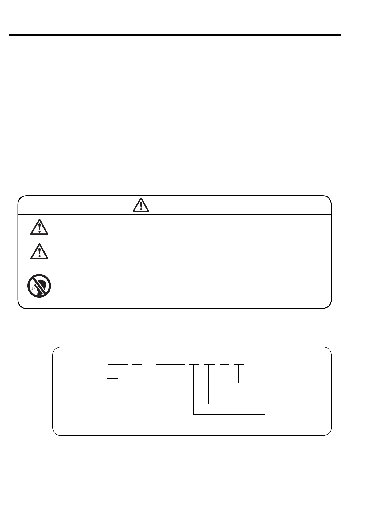
GRAPHIC DESCRIPTIONS:
WARNING
CAUTION
IMPORTANT
:This is a warning. If handled improp-
erly, death or severe injury could
result.
:This is a caution. If handled improp-
erly, injury and/or physical damage
could result.
:This graphic is Variable Speed-control
Drive (VSD) models.
:This graphic is for items that need
attention, other than WARNING and
CAUTION.
:
This graphic is a page number reference.
How to Use This Instruction Manual
● This Instruction Manual covers the standard models of the Hitachi DSP air compressor.
● This Instruction Manual intended to assist daily operators and maintenance personnel
in the installation, operation, control and service of the Hitachi DSP air compressor.
● Prior to operation of this air compressor, ensure that all operators read and understand
this INSTRUCTION MANUAL completely, thereby operating it safely and properly.
Place the INSTRUTION MANUAL near the air compressor to make it available at any
time, and refer to it as the need arises.
● If there are any questions or comments, please contact the local Hitachi distributor or
the nearest Hitachi office.
Fill your DSP’s model name, Serial Number, etc. into the back cover of this Instruction Manual.
●
Such information may be helpful when ordering parts, periodic maintenance, and overhaul.
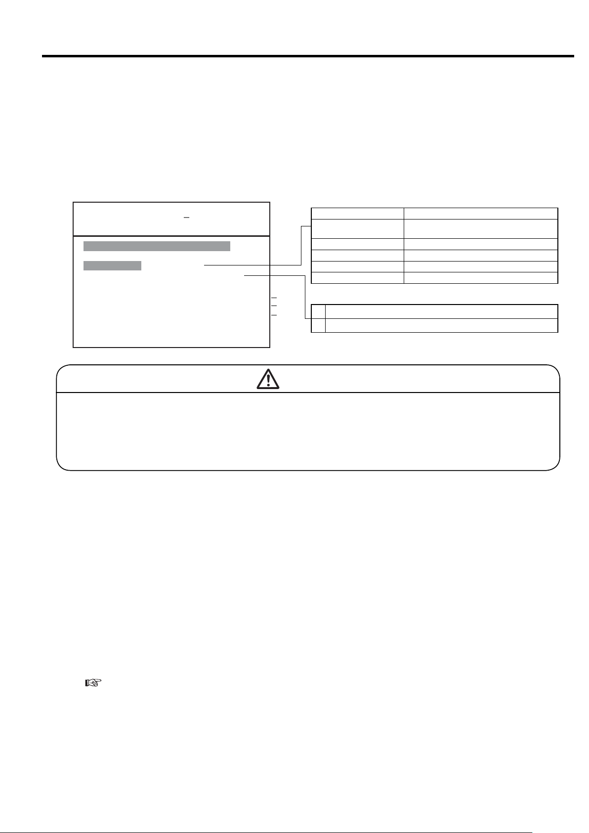
WARNING
Never remove a protective device from the air compressor or modify the air compressor.
It is imperative to install an earth leakage (ground) circuit breaker
on the power cable. This prevents a ground fault accident.
DSP air compressors are not designed, intended or approved for
breathing air applications. Hitachi does not approve specialized
equipment for breathing air applications and assumes no responsibility or liability for compressors used for breathing air services.
■ Model Number Nomenclature
DSP-160VW6N
Dry or Oil-Free Rotary
Screw Air Compressor
Packaged
● Hitachi may make improvements and/or changes in the products described in this publication at any time without notice.
N-Type (NEXT Series)
Frequency (6: 60 Hz)
W: Water-Cooled
w/ V: VSD, w/o V: Fixed
Motor Output (kW)

Contents
1. SAFETY ………………………………………………………………………………………… 2
2.
GENERAL DESCRIPTION
2.2 Components …………………………………………………………………… 5
2.3 Daily Operating Components ………………………………………………… 7
2.1 Appearance
………………………………………………………………………
4
3. OPERATING THE DSP 3.1 Instrument Panel………………………………………………………………… 10
3.2 Start/Stop Operation …………………………………………………………… 12
3.3 How to Use the liquid Crystal Display (LCD)………………………………… 13
3.4 How to Use the Digital Monitor ……………………………………………… 23
3.5 Daily Operation ………………………………………………………………… 30
3.6 Oil Mist Remover Daily Operation…………………………………………… 32
3.7 Adjusting the DSP ……………………………………………………………… 32
4. TROUBLESHOOTING 4.1 Protective Devices ……………………………………………………………… 33
4.2 Troubleshooting the Air Compressor………………………………………… 35
4.3 Troubleshooting the Oil Mist Remover……………………………………… 36
5. INSTALLING 5.1 Unpacking the DSP Air Compressor ………………………………………… 37
AND PIPING THE DSP 5.2 Conveying the DSP Air Compressor ………………………………………… 37
5.3 Installing the DSP Air Compressor ………………………………………… 38
5.4 Piping the DSP Air Compressor ……………………………………………… 39
5.5 Ventilation of Air Compressor Room………………………………………… 43
6. STARTUP OPERATION 6.1 Air Compressor ………………………………………………………………… 44
6.2 Oil Mist Remover ……………………………………………………………… 46
7. WIRING 7.1 Power Supply Transformer and Power Cable ……………………………… 47
7.2 MIV and WIVM wiring ………………………………………………………… 47
7.3 Connecting a Power Cable …………………………………………………… 47
7.4 Wiring Connection Diagram…………………………………………………… 50
7.5 Control Panel /LCD monitor Specifications ………………………………… 50
8.
STANDARD COMPONENTS
AND SUBSYSTEMS
8.3 Cooling Water…………………………………………………………………… 61
8.4 Capacity Control System ……………………………………………………… 62
8.5 Outline of Oil Mist Remover Subsystem …………………………………… 66
9.
MAINTAINING THE DSP
9.2 Standard Maintenance Schedule …………………………………………… 68
9.3 Oil Mist Remover Maintenance ……………………………………………… 72
9.4 How to Service the DSP Air Compressor…………………………………… 73
10.
PRECAUTIONS WHEN THE COMPRESSOR IS TO BE IDLE FOR AN EXTENDED PERIOD OF TIME
8.1 Standard Components ………………………………………………………… 57
8.2 Air/Oil Flow ……………………………………………………………………… 58
9.1 Air Compressor Maintenance………………………………………………… 67
…………… 84
11. PARTS LIST ………………………………………………………………………………………… 85
12. WARRANTY, AFTER-SALES AND SERVICE …………………………………………………………… 103
13. OPERATION RECORD LOGBOOK…………………………………………………………………………… 104
14. STANDARD SPECIFICATIONS ……………………………………………………………………………… 105
1
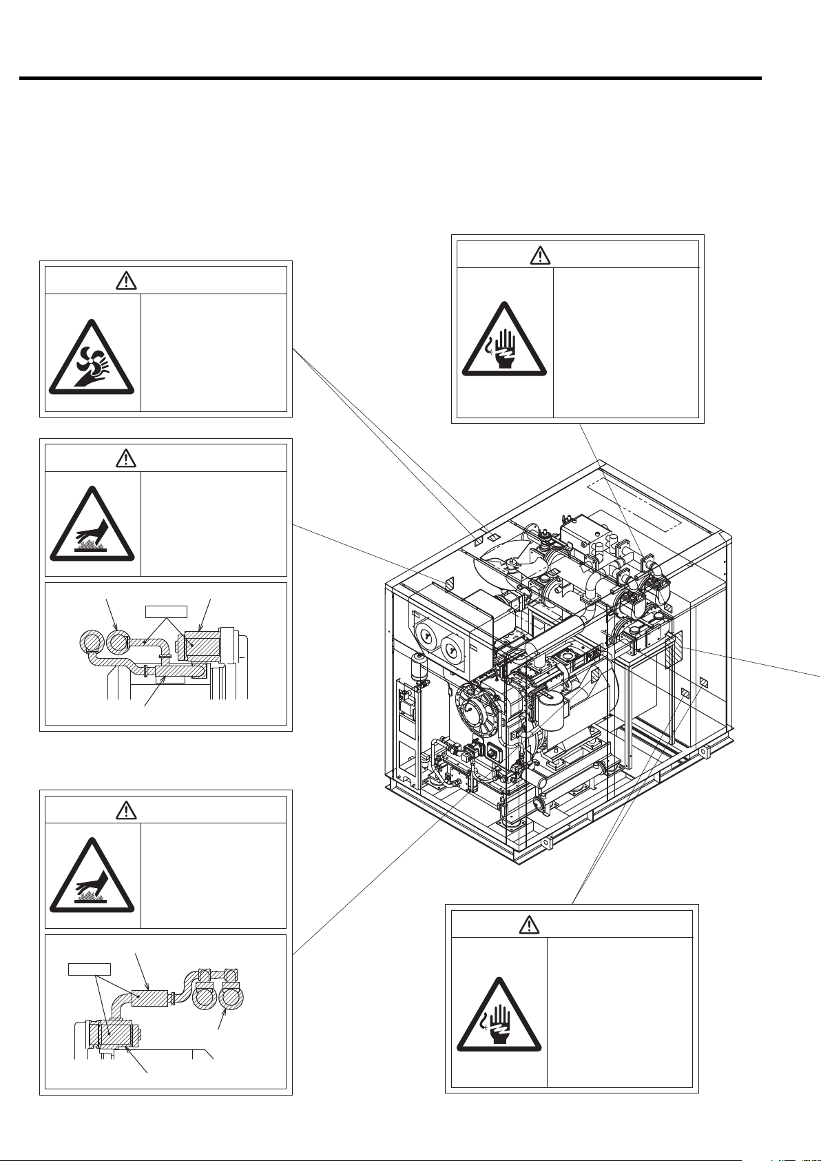
1. SAFETY
To ensure safe and proper operation of the air compressor, it is indispensable to carefully
read and understand the following warnings and instructions detailed below. These warnings and instructions are attached to the air compressor as shown in the figure below.
WARNING
WARNING
Rotating Parts!
●Keep hands and rods, etc. away from
the rotating parts (Cooling fans, etc.)
●Use caution at all times, when air com-
pressor is powered. The air compressor may be capable of restarting without hitting the START button.
●When the air compressor is operating,
do not remove or open the enclosure
panels and doors.
●Before servicing the air compressor,
stop it, disconnect the power, especially
when accessing any rotating parts.
WARNING
Hot Surface!
●Do not directly touch any component
inside the air compressor enclosure
when the air compressor is operating
or immediately after it has stopped,
as the components are extremely hot
and can cause severe injury.
●Before servicing the air compressor,
stop it, disconnect the power, then
wait for the air compressor to cool
down.
Electric Shock Hazard!
●Before servicing or wiring the
air compressor, disconnect
the power. This will prevent
anyone from turning on the
power and causing an electric shock that could lead to
severe injury or death.
●Do not allow any unlicensed
person to wire the air compressor. Always use a licensed
electrician.
●Ground the air compressor.
Intercooler Header
Discharge Air pipe
Discharge Air pipe
Heated!!
Air End
Heated!!
WARNING
Hot Surface!
●Do not directly touch any component
inside the air compressor enclosure
when the air compressor is operating
or immediately after it has stopped,
as the components are extremely hot
and can cause severe injury.
●Before servicing the air compressor,
stop it, disconnect the power, then
wait for the air compressor to cool
down.
Aftercooler Header
Air End
WARNING
Electric Shock Hazard!
●Before servicing or wiring the
air compressor, disconnect
the power. This will prevent
anyone from turning on the
power and causing an electric shock that could lead to
severe injury or death.
●Do not allow any unlicensed
person to wire the air compressor. Always use a licensed
electrician.
●Ground the air compressor.
2
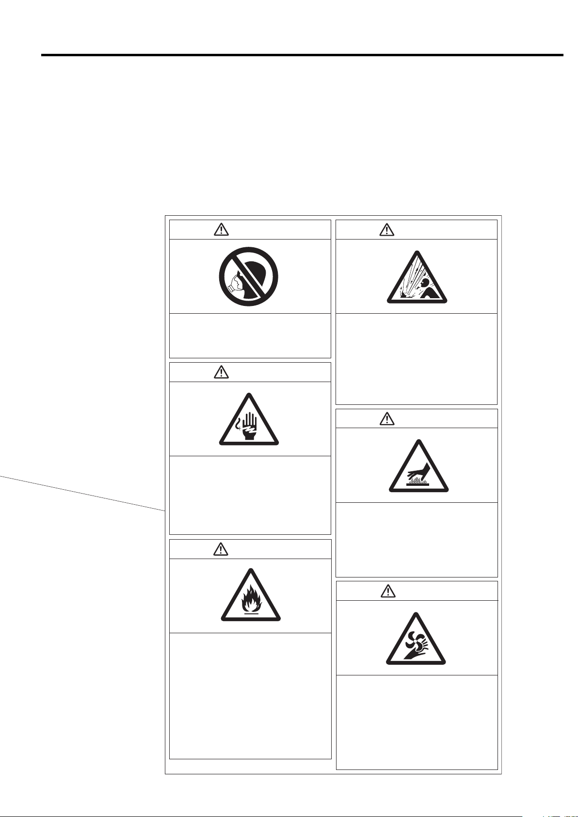
WARNING WARNING
1. SAFETY
Do Not Breathe Air!
Discharge air can contain Carbon Monoxide and
other contaminants. Breathing the air can cause
severe injury or death.
WARNING
Electric Shock Hazard!
●
Before servicing or wiring the air compressor,
disconnect the power. This will prevent anyone
from turning on the power and causing an electric
shock that could lead to severe injury or death.
●
Do not allow any unlicensed person to wire the air
compressor. Always use a licensed electrician.
●Ground the air compressor.
CAUTION
●
High pressure air can cause severe injury or death.
Be careful when air compressor is operating.
Pressurized air can blow out of safety relief valves
and etc. at incredibly high velocities.
●When using compressed air to clean equipment,
use extreme caution and/or wear eye protection.
●Before servicing the air compressor, stop it,
disconnect the power, and relieve pressure before
removing filter, plug, fitting or cover.
WARNING
High Pressure Air!
Hot Surface!
●Do not directly touch the air end, discharge air
pipe,and coolers when the air compressor is
operating and immediately after it has stopped,
because these parts are heated then.
Before servicing the air compressor (especially
●
when accessing to the heated parts), stop it, disconnect the power, and wait until it is cooled down.
WARNING
●
Preoaution against Fire!
Keep any other hazardous materials such as
flammable solvents away from the air compressor.
Also do not use fire nearby it; otherwise a spark
may enter the air compressor and burn it internally.
●Do not remove any protective relayʼ s. Also do
not make a modification of the control circuit that
may result in impairing the protective relayʼ s
function. Remember that the loss of the protective
relayʼ s function may cause serious damage.
●Install an earth leakage circuit breaker between
the air compressor and the power supply. Do not
use a disconnector such as a knife switch
because it cannot protect the air compressor and
may cause burnout of the air end if a ground fault
has occurred.
Rotating Parts!
●Keep hands and rods, etc. away from the rotating
parts (Cooling fans, etc.)
●Use caution at all times, when air compressor is
powered. The air compressor may be capable of
restarting without hitting the START button.
●When the air compressor is operating, do not
remove or open the enclosure panels and doors.
●Before servicing the air compressor, stop it, dis-
connect the power, especially when accessing
any rotating parts.
3
2. GENERAL DESCRIPTION
This section illustrates and describes the major components of the DSP air compressor. Be familiar
with the name, location and function of each component before using the DSP air compressor.
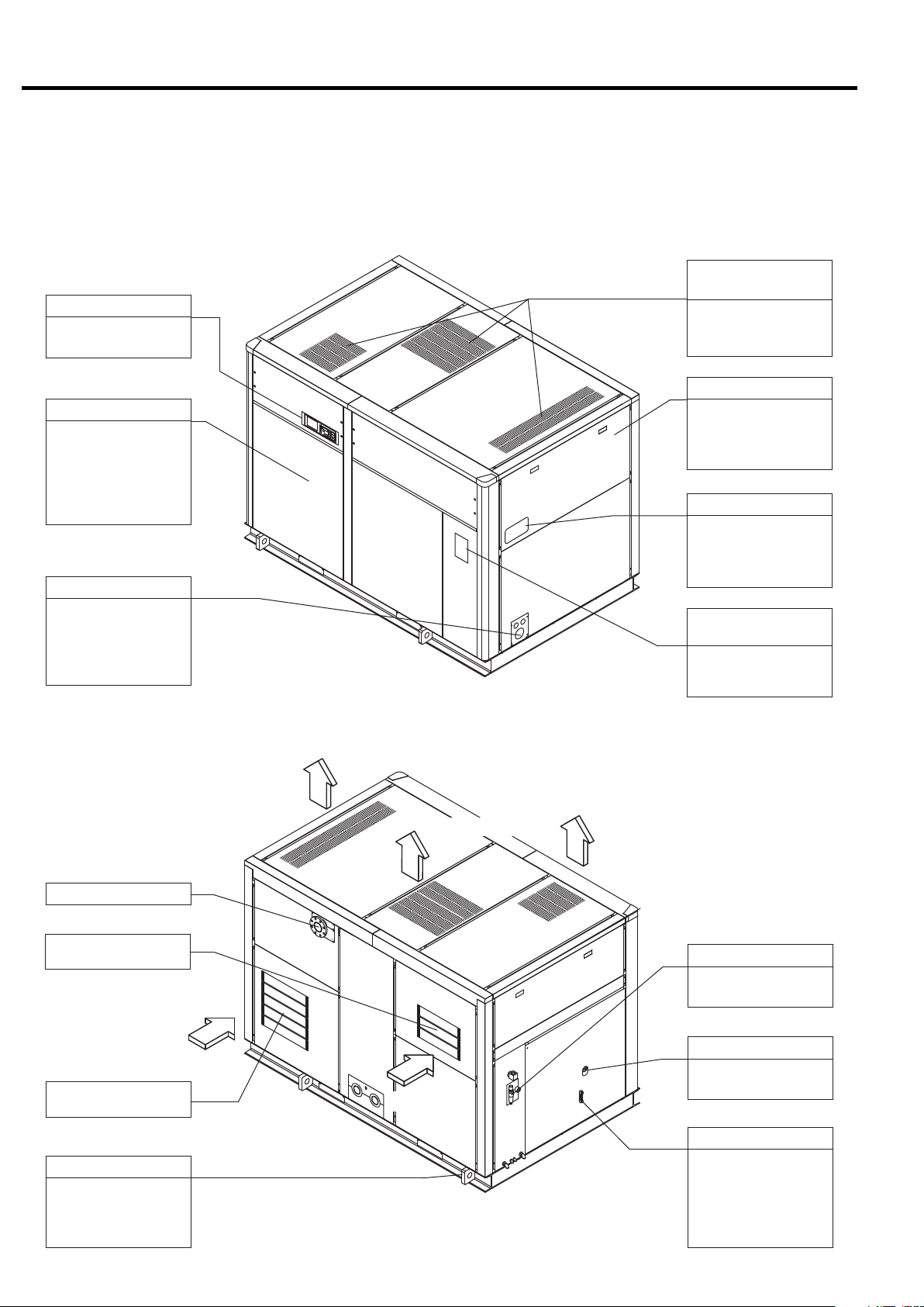
2.1 Appearance
2.1.1 Fixed Speed
[Front View]
Air Exhaust
(Air Compressor Package)
Instrument Panel
See page p. 10, chapter 3, for details.
Front Left Door
Open the front left
door only when servicing the DSP air compressor. Keep it closed
when operating the
DSP air compressor.
Power Supply Port
Check the specifications, power supply
and voltage before
connecting the power
supply.
This panel discharges
the hot air generated
in the air compressor.
Enclosure
Enclosure panels
lower the sound level
of the air compressor
package.
Compressor Name plate
Model designation,
manufacturing number
and specification are
printed.
Plate of Operating /
Servicing Instructions
Read carefully the
plate before operating
and servicing the DSP.
[Rear View]
Compressed Air Discharge
Air Intake
(Inlet to the Air End)
Air Intake
Air Intake
(Air Compressor Package)
Sling Fitting
Use the sling fitting
when moving and
installing the DSP air
compressor.
Air Exhaust
Air Exhaust
Air Exhaust
OMR
See page 55 for the
details
Oil Filling Port
Use the port to fill the
gear case with oil.
Air Intake
Oil Level Gauge
This indicates the
quantity of the oil in
the gear case. Check
the oil level before
starting the DSP and
when operating it.
4
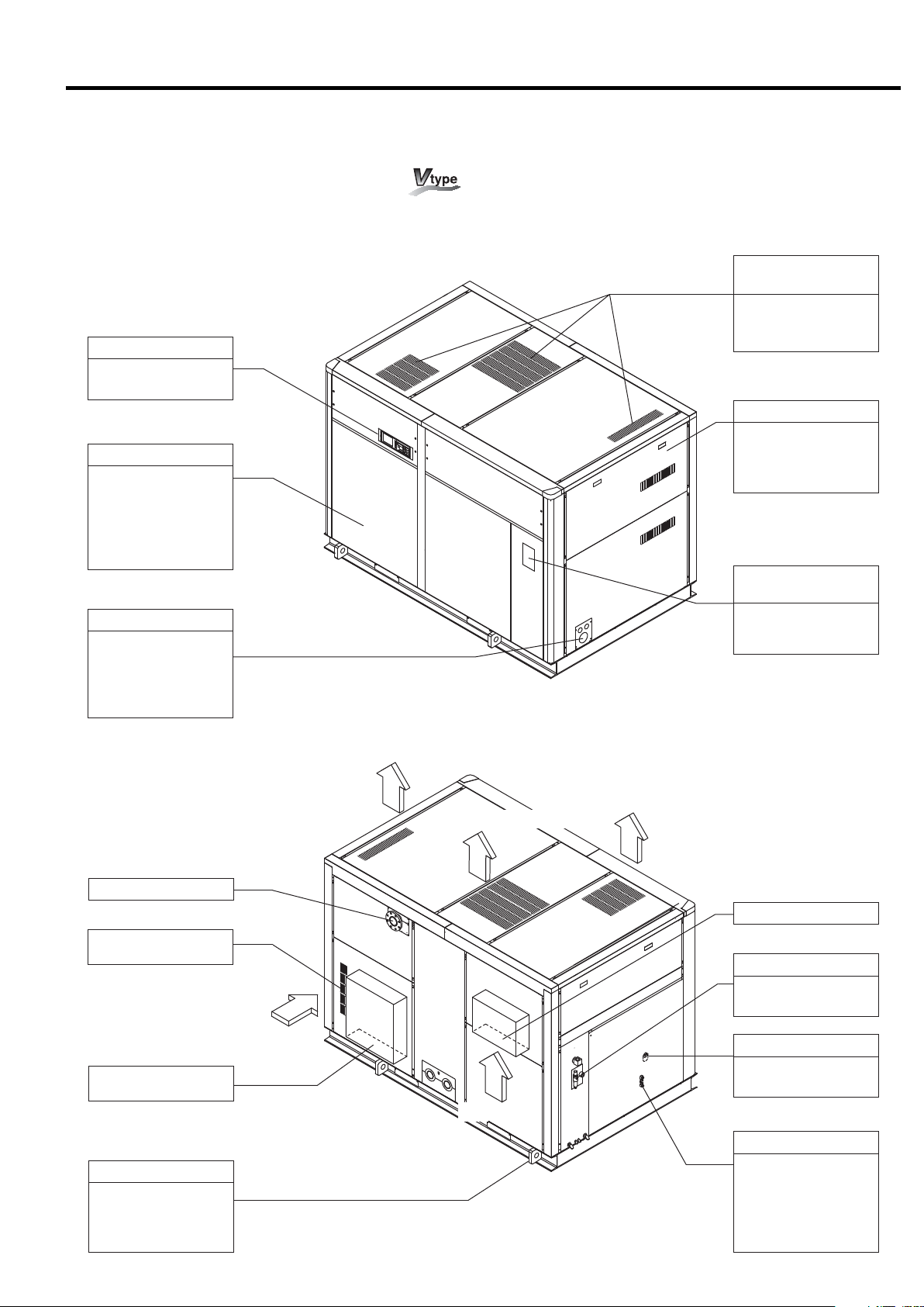
2.1.2 Variable Speed Drive Control
[Front View]
Instrument Panel
See page p. 10, chapter 3, for details.
Front Left Door
Open the front left
door only when servicing the DSP air compressor. Keep it closed
when operating the
DSP air compressor.
Power Supply Port
Check the specifications, power supply
and voltage before
connecting the power
supply.
2. GENERAL DESCRIPTION [Appearance]
Air Exhaust
(Air Compressor Package)
This panel discharges
the hot air generated
in the air compressor.
Enclosure
Enclosure panels
lower the sound level
of the air compressor
package.
Plate of Operating /
Servicing Instructions
Read carefully the
plate before operating
and servicing the DSP.
[Rear View]
Compressed Air Discharge
Air Intake
(Inlet to the Inverter)
Air Intake
Air Intake
(Air Compressor Package)
Sling Fitting
Use the sling fitting
when moving and
installing the DSP air
compressor.
Air Exhaust
Air Exhaust
Air Exhaust
Compressed Air Discharge
OMR
See page 66 for the
details
Oil Filling Port
Use the port to fill the
gear case with oil.
Air Intake
Oil Level Gauge
This indicates the
quantity of the oil in
the gear case. Check
the oil level before
starting the DSP and
when operating it.
5
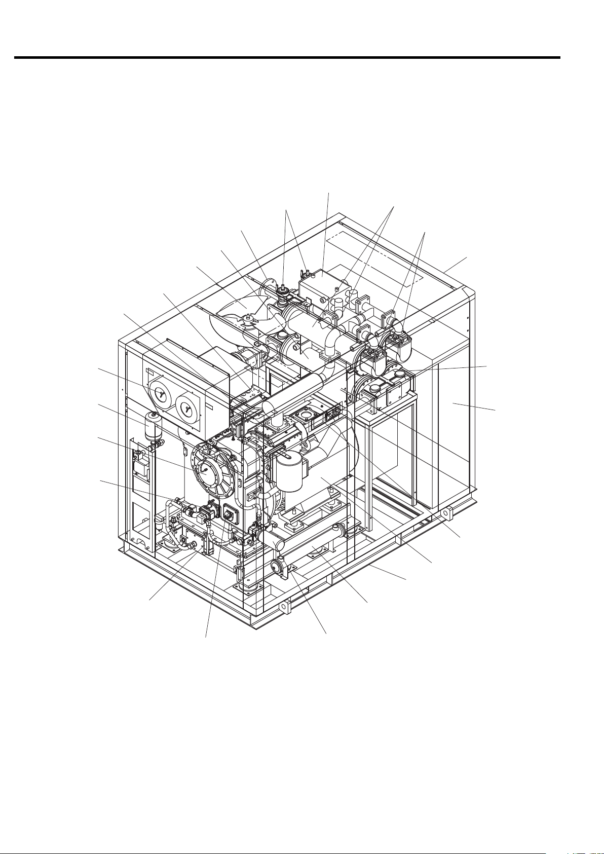
2. GENERAL DESCRIPTION [Components]
2.2 Components
Discharge Pipe
(Compressed Air Discharge)
Blow-off air cooler
Safety Relief Valve
Aftercooler
Check Valve
2nd-Stage Air end
Air Intake Filter
Oil Mist Remover
Gear Case
Oil Pump
Ventilating Fan
1st-Stage Air end
Intercooler
Enclosure
Intercooler
Starter /
Control Box
Instrument Panel
Main Motor
Common Base
Oil Level Gauge
Oil Filling Port
Oil Filter
Oil Cooler
6
2. GENERAL DESCRIPTION [Daily Operating Components]
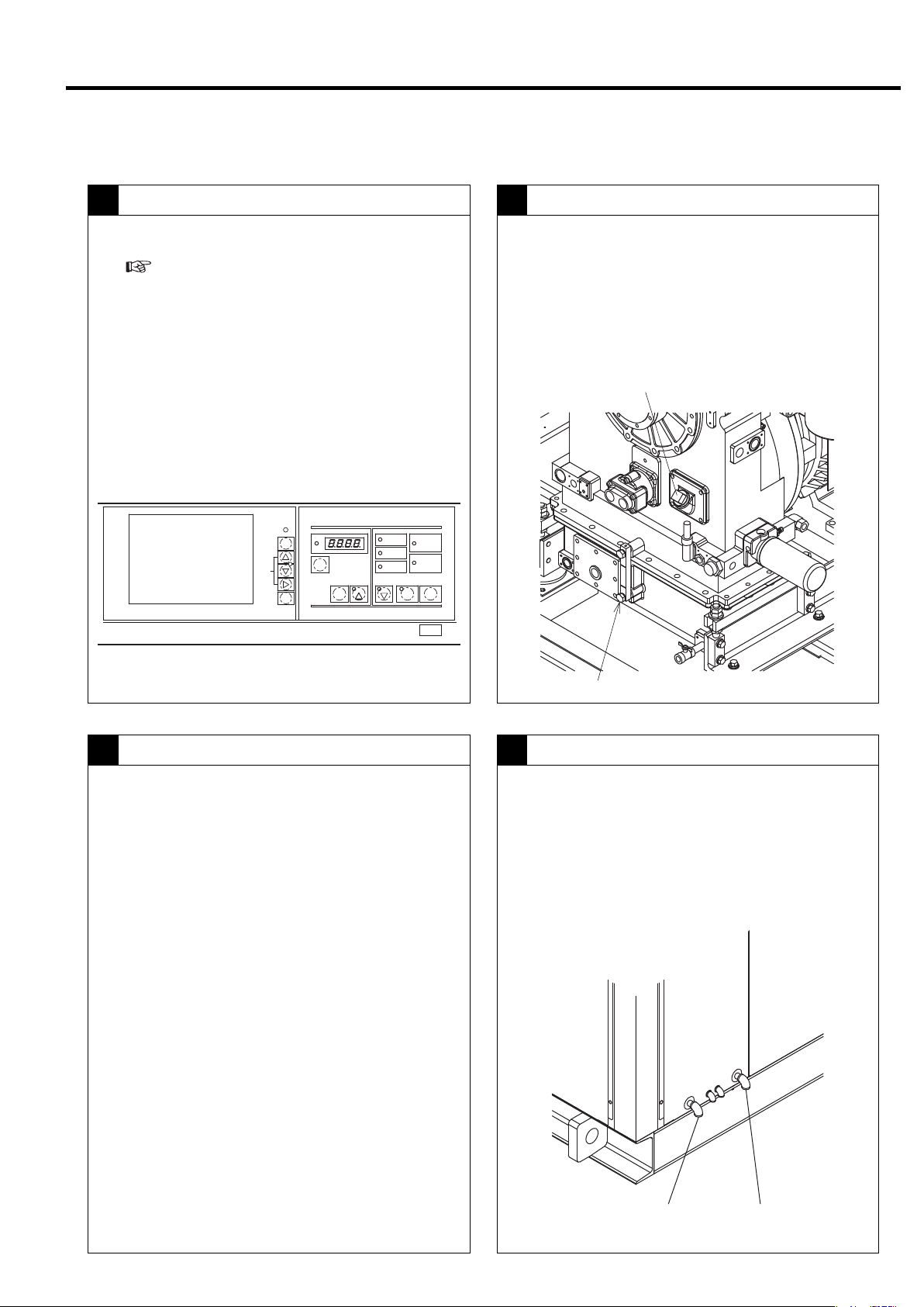
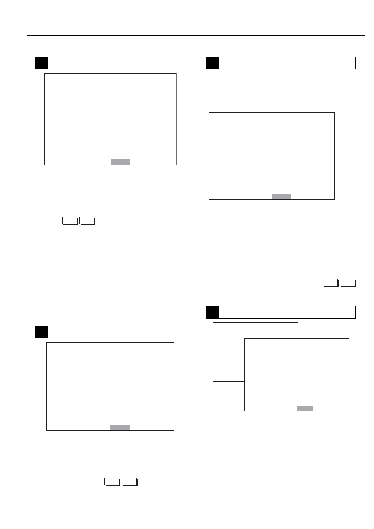
2.3 Daily Operating Components
Controls on the Instrument Panel
1 2
● Indicates the operation control section.
(
For more information, see Chapter 3, on
page 10.)
● Operation ON → POWER light on.
● Start: Press START button → Operation Light on
during operation
● Stop: Press UNLOAD STOP button →
unloading
stops for 5 minutes → Operation Light off during
operation
● Power OFF: → POWER light off
MONITOR
自動
AUTO
モニタ
MONITOR
メニュー
MENU
+/−
UP/
DOWN
設定
SET
運転管理
RUNNINGCONTROL
警報
ALARM
機能
FUNC
リセット
RESET
遠方
記憶
STR
[×10h]
表示切替/
ワイド モード
SELECT/WIDE
1
運転状況
RUNNINGMODE
遠方
REMOTE
負荷
LOAD
故障
SHUTDOWN
2
電源
POWER
起動待ち
AUTOSTART
運転 停止
STOP
STARTREMOTE
UNLOAD STOP
Oil Level Gauge
● Verify that the oil level of the lubricating oil is
between the red lines during operation.
Lubricating oil circulates in the cooler and piping during
operation, so the position of the oil level differs when the
compressor is running and when it is off. The level rises
when the compressor stops running.
Oil Filling Port
Lubricating Oil
3 4
Oil: Use genuine Hitachi GL-68 DSP Compressor Oil.
Replace the oil every 8,000h operating hour or
every 2-year, whichever comes earlier.
Oil Level Gauge
Aftercooler and Intercooler - Condensate Drain Valve
● Verify that air containing drainage is discharged
intermittently from the intercooler and after cooler
drain ports.
The higher the temperature and humidity, the more drainage
is produced. Drainage may not be produced on the intercool-
er side during winter.
After cooler
drain port
Intercooler
drain port
7
2. GENERAL DESCRIPTION [Daily Operating Components]
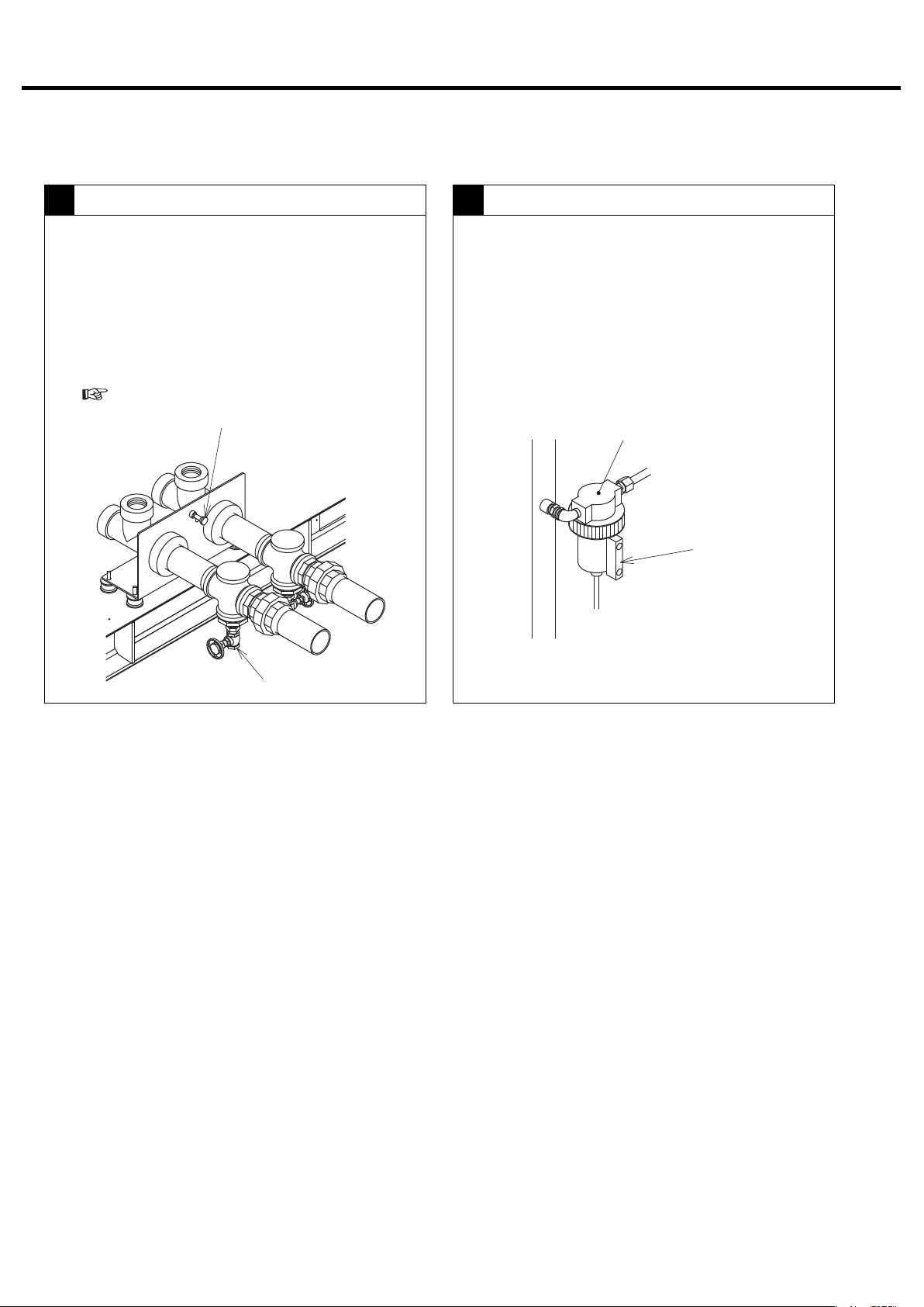
Cooling Water
5
① Shut off the cooling water when the compressor is
off.
② Open the peacock for draining water. Also open
the valve of the water drain port and drain the
cooling water.
③ Be especially careful of freezing during the winter.
(
For details, see page 61.)
Water drain peacock
Control Line Filter (Fixed Speed)
6
● Check the condensate drain discharge from the
control line filter by checking the sight glass on the
control line filter.
Control Line Filter
Sight Glass
Water drain port
8
2. GENERAL DESCRIPTION [Daily Operating Components]
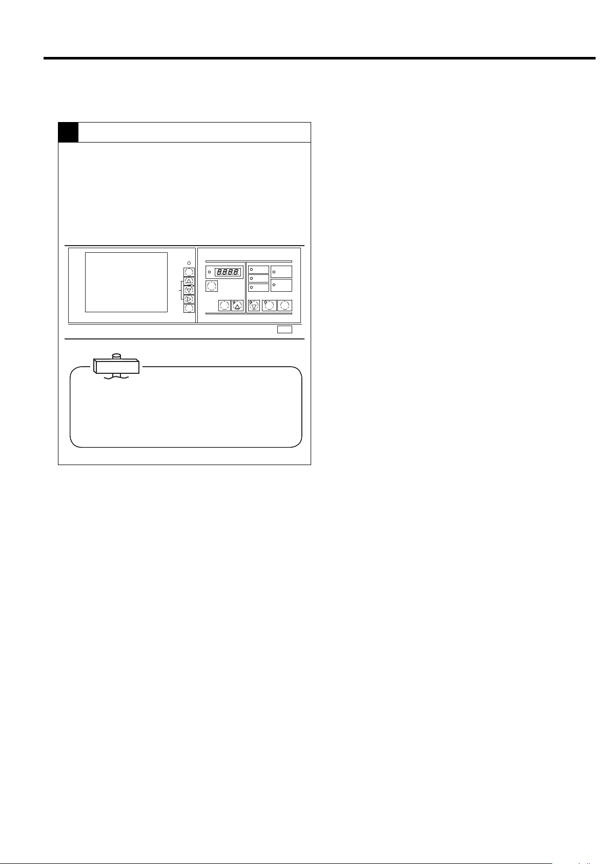
Stopping operation
7
●Normally use UNLOAD STOP button to stop the
compressor. The compressor then unloads for 5
minutes and stops running.
(In the case of an emergency, press the STOP
button to stop operation.)
MONITOR
自動
AUTO
モニタ
MONITOR
メニュー
MENU
+/−
UP/
DOWN
設定
SET
運転管理
RUNNINGCONTROL
警報
ALARM
機能
FUNC
リセット
RESET
遠方
記憶
STR
[×10h]
表示切替/
ワイド モード
SELECT/WIDE
1
運転状況
RUNNINGMODE
遠方
REMOTE
負荷
LOAD
故障
SHUTDOWN
2
電源
POWER
起動待ち
AUTOSTART
運転 停止
STOP
STARTREMOTE
UNLOAD STOP
IMPORTANT
Keeping the second-stage air end as dry as possible is
essential for preventing it from rusting due to a longterm operation suspension. When stopping the DSP,
therefore, execute an unloading operation and thereby
remove the moisture from the second-stage air end.
9
3. OPERATING THE DSP
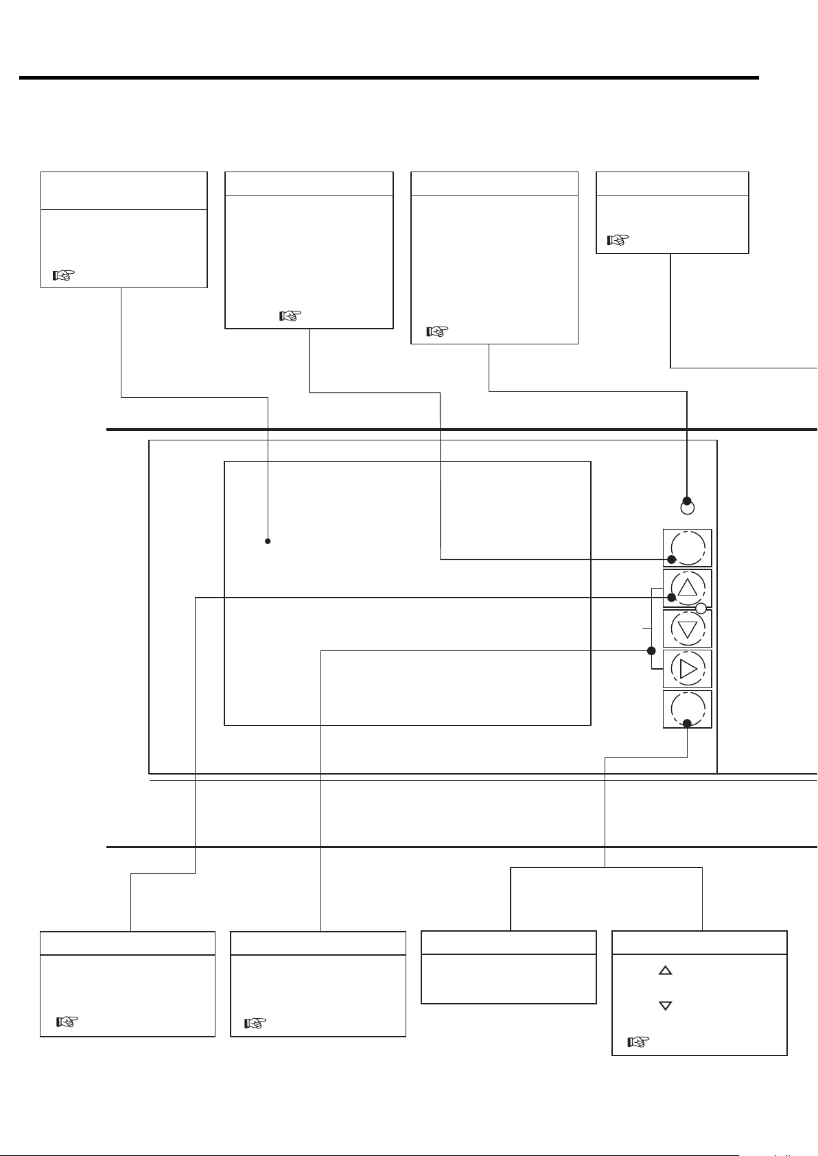
3.1 Instrument Panel
Liquid Crystal Display
(LCD)
Displays the operation data,
various setting, shutdowns/
alarms information, etc
( page 13)
MONITOR Button
Enables movement within
each of the monitoring
displays (M1, M2) and the
message display (M3). This
button also enables you to
return to the M1 display from
the FUNCTION MENU
display ( page 13).
AUTO light (yellow)
ON (glowing) when an
automatic operation (an
AUTO operation, a scheduling operation, or lead/lag
operation) is activated.
ON (flashing) when external
calendar or scheduling
operation is abnormal.
( page 16, 20)
RESET Button
Reset the system or cancels
the shutdown/alarm circuit
( page 15)
自動
AUTO
モニタ
MONITOR
メニュー
MENU
MENU Button
Functions to display the
menu screen and move the
cursor.
( page 18)
MONITOR
+/- UP DOWN Buttons
Each of these buttons act as
an up-arrow, down-arrow
and right-arrow key.
( page 18)
SET Button
It saves any adjusted set
points.
+/−
UP/
DOWN
設定
SET
Contrast adjustment
SET+[ ] button operation:
Brightens the display.
SET+[ ] button operation:
Darkens the display.
( page 22)
10
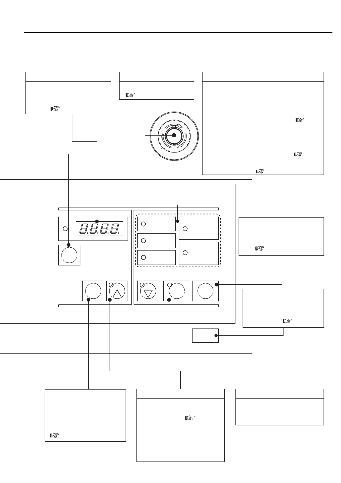
3. OPERATING THE DSP [Instrument Panel]
Digital Monitor
In addition to basic settings, used
to set various types of setting
values in combination with the LCD
monitor. ( page 22)
運転管理
RUNNINGCONTROL
警報
ALARM
機能
FUNC
リセット
RESET
遠方
記憶
STR
ワ イド モ ード
EMERGENCY STOP button
Stops for emergency.
( page 12)
遠方
REMOTE
負荷
[× 10h]
LOAD
故障
SHUTDOWN
表示切替/
SELECT/WIDE
1
2
G
E
R
N
E
M
E
S
C
Y
P
T
O
運転状況
RUNNINGMODE
電源
POWER
起動待ち
AUTOSTART
運転 停止
STARTREMOTE
RUNNING MODE Light
POWER light (yellow):
ON (glowing) when the power to the air compressor is turned on.
REMOTE light (green):
ON (glowing) when the REMOTE button is pressed in
order to activate a remote operation.
ON (flashing) when an external remote-operation-activation switch has
been turned on in order to activate a remote operation.
LOAD light (yellow):ON (glowing) when the air compressor is loading.
AUTO START light (green):
ON (glowing) while the air compressor is in a stop due to an
AUTO operation, lead/lag operation, or scheduling operation.
ON (blinking) while the air compressor is in a stop due to a
restartable instantaneous power interruption. ( page 16)
SHUTDOWN light (red):
ON (either glowing or blinking) when a shutdown/alarm
problem has occurred. ( page 15)
( page 28)
STOP Button
Used to stop the compressor
immediately without first unloading. ( page 12)
STOP
UNLOAD STOP Button
Press this button to stop the air compressor.
The air compressor will stop after removing the
condensate from the air end.
※This stop button is effective while a stand alone operation.
REMOTE Button
Activates or deactivates a remote
start/stop operation locally or on
the instrument panel. it also acts
as a right-arrow key stop
( page 28).
UNLOAD STOP
SELECT/WIDE Button/Light (Yellow)
Press to confirm various types of
setting values, shutdown history,
and setting status. (
To set to ECONOMODE (energy
conservation mode) (standard type
only), press and hold the SELECT/
WIDE button for at least 7 seconds.
The light flashes and ECONOMODE
is set.
page 24, 25
)
Used for normal stop. Stops
after the compressor and air
hoses are dry. ( page 12)
START Button
Starts the air compressor.
The OPERATION light (red) turns
on while the compressor is running.
11
3. OPERATING THE DSP [Start/Stop Operation]
3.2 Start/Stop Operation
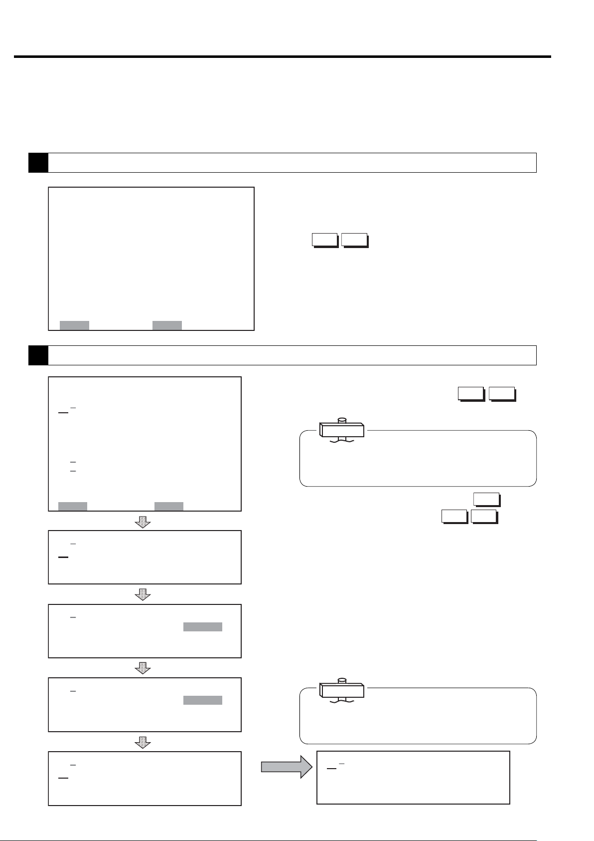
3.2.1 Connecting the Power
When you connect the power, the POWER light turns on
and the LCD monitor displays the following screen for 5
seconds, and then switches to the monitor screen (M1)
that displays control settings, discharge air pressure, and
total operating hours.
COMPRESSOR MONITOR
CONTROLLER
5 sec
㻞㻜㻜㻥䠋㻜㻠䠋㻝㻟 㻝㻥䠖㻜㻞
㼀㼅㻼㻱䠖㼂㻿㻰㻭
㻰 㻵 㻿䠊㻼㻾㻱㻿㻿 䠖 㻜䠊㻜 㻜㼜 㼟 㼕
㻾㼁㻺 㻌㻴㻻㼁㻾 䠖 㻝 㻞 㻜 䡄
㻸㻻㻭㻰 㻌 㻴㻻㼁㻾 䠖 㻡 㻠䡄
㻸㻻㻭㻰 㼀 㻵 㻹㻱㻿 䠖 㻝㻞 㻟
㻸㻻㻭㻰 㻾㻭㼀㻱䠖 㻝 㻝䠂
㻸㻻㻭㻰 㼀 㻵 㻹㻱 䠖 㻞 㻠䡏
㼁㻺㻸㻻㻭㻰 㻌 㼀 㻵㻹㻱 䠖 㻝䡏
㻯㼁㻾㻾㻱㻺㼀 䠖 㻡 㻜䠝
㻲㻾 㻱㻽㼁㻱 㻺㻯㼅䠖 㻞 㻟 㻚 㻤䠤䡖
㻻㼁㼀㻼㼁㼀䠖 㻝 㻜 㻚 㻡䡇䠳
3.2.2 Start/Stop
When the START button is pressed the START light
turns on and the compressor starts operating. When running, the asterisk on the right side of running hours
flashes and running time is counted.
To stop, press the UNLOAD STOP button. Operation
stops when the air end and the air piping have dried for 5
minutes.
To stop the compressor immediately without unloading,
press the STOP button.
Note: If the STOP button is pressed while unloading, the
compressor stops immediately.
3.2.3 Emergency Stop
Pressing EMERGENCY STOP botton, the DSP compressor immediately.
This switch should only be pressed in emergency.
The compressor can not be restarted until the switch is
manually reset. Turn the switch knob clockwise and
press the RESET button to reset.
*The asterisk flashes when the clock and total run-
ning hours are engaged.
If phase is reversed, “Connection Error: Reverse
Phase” is displayed on the LCD monitor for setting and
connection inspection. In this case, switch 2 of the 3
main power cables.
If there is no phase, “Connection Error: No Phase” is
displayed on the LCD monitor. In this case, check the
power cables.
12
3. OPERATING THE DSP [How to Use the Liquid Crystal Display (LCD)]
3.3 How to Use the liquid Crystal Display (LCD)
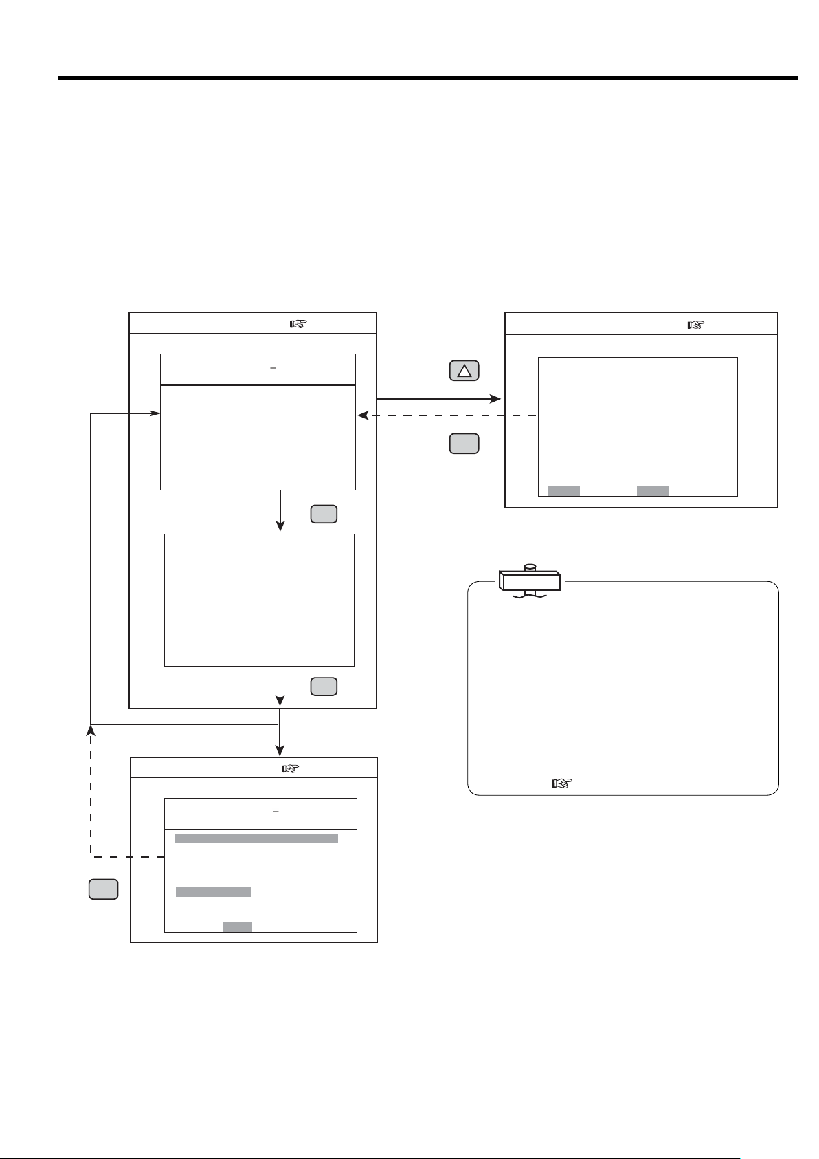
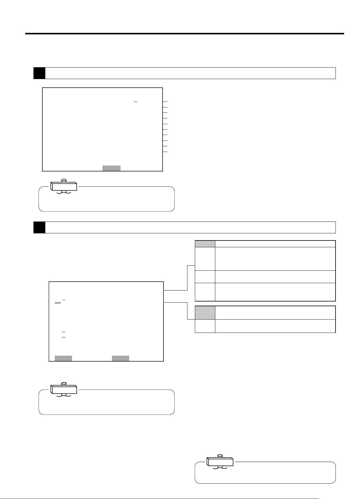
3.3.1 How to Move between the Various Displays
■Monitoring Displays
There are three monitoring displays: M1, M2, and
M3. To move between these displays, press the
MONITOR button.
■Monitoring Display(p.12)
M1 Monitoring Display
㻞㻜㻜㻥䠋㻜㻠䠋㻝㻟 㻝㻥䠖㻜㻞
㼀㼅㻼㻱 䠖㼂㻿㻰㻭
㻰 㻵 㻿䠊㻼㻾 㻱㻿㻿 䠖 㻜䠊 㻜 㻜 㼜 㼟 㼕
㻾㼁㻺 㻌㻴㻻㼁㻾 䠖 㻝 㻞㻜 䡄
㻸㻻㻭㻰 㻌 㻴㻻㼁㻾 䠖 㻡 㻠 䡄
㻸㻻㻭㻰 㼀 㻵 㻹㻱㻿 䠖 㻝 㻞 㻟
㻸㻻㻭㻰 㻾㻭㼀㻱 䠖 㻝㻝䠂
㻸㻻㻭㻰 㼀 㻵 㻹㻱 䠖 㻞㻠 䡏
㼁㻺㻸㻻㻭㻰 㻌 㼀 㻵 㻹㻱䠖 㻝䡏
㻯㼁㻾㻾㻱㻺㼀 䠖 㻡 㻜䠝
㻲㻾㻱 㻽㼁㻱㻺㻯 㼅䠖 㻞 㻟 㻚 㻤䠤䡖
㻻㼁㼀㻼㼁㼀䠖 㻝㻜 㻚 㻡 䡇䠳
モニタ
モニタ
MONITOR
M2 Monitoring Display
㻞㻜㻜㻥䠋㻜㻠䠋㻝㻟 㻝㻥䠖㻜㻞
㻼㻾㻱㻿㻿㼁㻾㻱
㻵 㻺㼀 㻿 㼀㻳 䠊 㻼 䠖 䚷䚷 㻞 㻥 㼜 㼟 㼕
㻻 㻵 㻸 㻌 㻼㻾㻱㻿 䠖 㻌 㻌 㻝㻡 㼜 㼟 㼕
㻯㻸㼀䠊㻼 㻾㻱㻿 䠖 㻖䠊㻖 㻖 㼜 㼟 㼕
㼀㻱㻹㻼㻱㻾㻭㼀㼁㻾㻱
㻰㻵㻿䠊㼀㻱㻹㻼㻝䠖 㻟㻞㻜䉣
㻰 㻵 㻿䠊㼀㻱㻹㻼 㻞 䠖 㻟㻝㻟㻤䉣
㻻 㻵 㻸 㻌 㼀 㻱㻹㻼 䠖 㻟 㻣 䉣
㻯㻸㼀䠊㼀㻱㻹㻼䠖 㻖㻖㻖䉣
㻞㻺㻰 㻌 㻿㼁㻯㼀䠊㼀䠊 䠖 㻜 㻤䉣
㻹㻭 㻵 㻺㼀㻱㻺 㻭㻺㻯㻱
㻴㻾䠊㼀㻻㻌㻹㻭㻵㻺㼀䠖 㻜㻜㻜㻜䡄
㻺㻱㼄㼀㻌㻹㻭 㻵㻺㼀䠖 㻖㻖㻖㻖
■Message Display(p.13)
M3 Monitoring Display
㻞㻜㻜㻣䠋㻜㻤䠋㻜㻝 㻝㻥䠖㻝㻥 㻖
㼀㼅㻼㻱 䠖㼂㻿㻰㻭
㻰 㻵 㻿䠊㻼㻾 㻱㻿㻿 䠖 㻜䠊 㻠 㻢
䠘㻿 㻴 㼁 㼀 㻰 㻻 㼃 㻺䠚
㻯㻻㻻㻸㻭㻺㼀䠖
㻻㻵 㻸䠖
㻞䠪㻰 㻌 㻿 㼁㻯 㼀䠊 㼀 㻱
㻴㻵㻳㻴 㻌㻰㻵㻿䠊㼀㻱㼜㼟㼕
㻯 㻻 㻺 㼀 㻭 㻯 㼀 㻻 㻾 㻌㻱 㻾 㻾 䠖
㻻㼂㻱㻾 㻸㻻㻭㻰 䠖
㻸㻻㼃 㻌㼃 䠊 㻵 㻺 㼀 㻿 㼀㻳 㻌 㻼䠊
㻰 㻾 㼅 㻱 㻾 㻌㻌㻌㻌 㼃 䠋 㻻 㻌 㻿 㻱 㻼 䠊
㻱㻸 㻱㻹㻱㻺 㼀
㻼㼞㼑㼟㼟㻾㻱㻿㻌㼍㼒㼠㼑㼞㻌㻯㻴㻷䠊
㼀㼁
㼜㼟
MONITOR
㻝
モニタ
MONITOR
㼜㼟㼕
㼕
■Menu Displays
Follow the bottom line message on the display.
■Function Menu Display(p.16)
機能
FUNCTION
モニタ
MONITOR
Function Menu Display
㼇 㻲㼁㻺㻯㼀 㻵㻻㻺 㻹㻱 㻺㼁 㼉
㻝䠊㻮㻭㻿 㻵㻯 㻌 㻿 㻱㼀 㼁㻼
㻞䠊㻹 㼁㻸 㼀 㻵 㻙㼁 㻺 㻵 㼀
㻟䠊㻯㻭㻼 㻭㻯 㻵 㼀㼅 㻯㻻㻺㼀㻾㻻㻸
㻠䠊㻿㻯㻴㻱㻰 㼁㻸㻱
㻡䠊㻻㻼㻱㻾㻭㼀㻵 㻻㻺 㻰㻭㼀㻭
㻢䠊 㻸㻻㻭㻰 㻰㻭㼀㻭
㻣䠊㻭㻸㻭㻾㻹 㻴 㻵 㻿㼀㻻㻾㼅
㻤 䠊㻿 㻴㼁 㼀 㻰㻻㼃㻺 㻴 㻵 㻿㼀 㻻㻾 㼅
㻿㻱㼀䠖㻻㻼㻱㻺 㻹㻻㻺䠖㻮㻭㻯㻷
IMPORTANT
About the LCD Backlight
(1) In the event that no button has been used for 10
minutes, the LCD backlight automatically turns OFF
for protection to the display panel. It comes ON
again if any button is pressed, other than the
START and STOP buttons.
(2) If an event happens while the LCD backlight is off,
the backlight automatically turns ON and stays ON
as long as the event exists. Remote and instant
stop mode can't be set by the LCD monitor.
Set after referring to “3.4 How to Use the Digital
Monitor.” (
page 21)
■ Message Display
There is only one message display: M3 (the contents,
however, vary from time to time). It is available only
when some event (air compressor alarm or shutdown,
maintenance notice, etc.) has occurred. Once an event
happens, however, the M3 message display appears
immediately and automatically. From the M3 display,
pressing the MONITOR button will switch the LCD
to the M1 or M2 monitoring displays; but after
approximately ten (10) seconds, the M1 or M2 monitoring displays will revert back to the M3 display.
13
3. OPERATING THE DSP [How to Use the Liquid Crystal Display (LCD)]
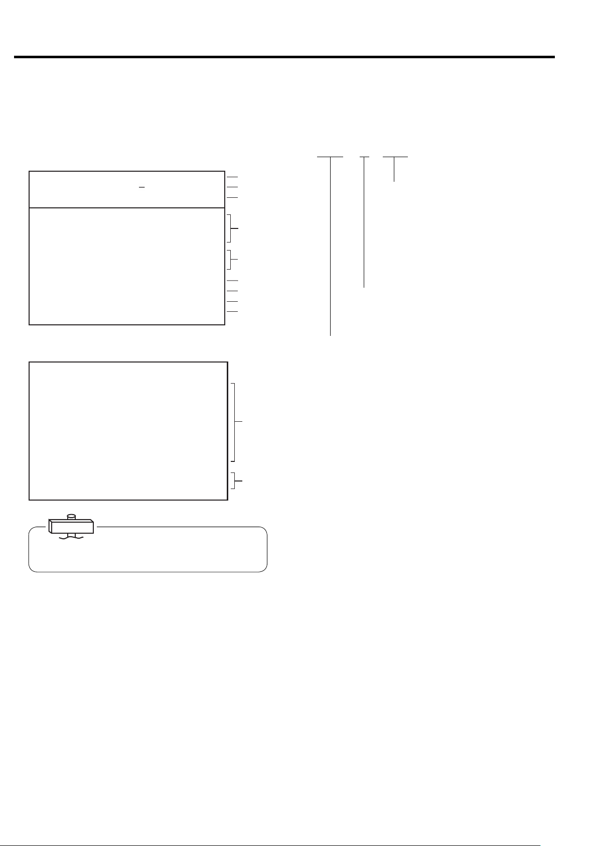
3.3.2 Typical Monitoring Displays
When the DSP is operating normally, typical monitoring
displays appear as follows.
M1 Monitoring Display
㻞㻜㻜㻥䠋㻜㻠䠋㻝㻟 㻝㻥䠖㻜㻞
㼀㼅㻼㻱䠖㼂㻿㻰㻭
㻰 㻵 㻿䠊㻼㻾㻱㻿㻿 䠖 㻜 䠊㻜 㻜 㼜 㼟 㼕
㻾㼁㻺 㻌㻴㻻㼁㻾 䠖 㻝 㻞 㻜 䡄
㻸㻻㻭㻰 㻌 㻴㻻㼁㻾 䠖 㻡 㻠 䡄
㻸㻻㻭㻰 㼀 㻵㻹㻱㻿 䠖 㻝 㻞 㻟
㻸㻻㻭㻰 㻾㻭㼀㻱䠖 㻝㻝䠂
㻸㻻㻭㻰 㼀 㻵㻹㻱 䠖 㻞 㻠 䡏
㼁㻺㻸㻻㻭㻰 㻌 㼀 㻵 㻹㻱 䠖 㻝䡏
㻯㼁㻾㻾㻱㻺㼀 䠖 㻡 㻜䠝
㻲㻾 㻱㻽㼁㻱㻺㻯 㼅 䠖 㻞 㻟 㻚 㻤䠤䡖
㻻㼁㼀㻼㼁㼀䠖 㻖 㻖 㻚 㻖 䡇䠳
㻹㻭㻿㼀㻱 㻾
(1)
㻖
(2)
(3)
㻖
(4)
(5)
(6)
(7)
(8)
(9)
VSDA*SAVE
Displayed when stop is limited for AUTO operation (standard: no symbol).
ECOMODE
(Energy Conservation Mode)
“SAVE” is displayed on the monitor
screen.
M2 Monitoring Display
㻞㻜㻜㻥䠋㻜㻠䠋㻝㻟 㻝㻥䠖㻜㻞
㻼㻾㻱㻿㻿㼁㻾㻱
㻵 㻺㼀㻿 㼀㻳䠊㻼 䠖 㻌 㻌 㻞 㻥 㼜 㼟 㼕
㻻 㻵 㻸 㻌 㻼㻾㻱㻿䠖 㻌 㻌 㻝㻡 㼜 㼟 㼕
㻯㻸 㼀䠊㻼㻾㻱 㻿 䠖 㻖䠊 㻖 㻖 㼜 㼟 㼕
㼀㻱㻹㻼㻱㻾㻭㼀㼁㻾㻱
㻰㻵 㻿䠊㼀㻱㻹㻼㻝䠖 㻟㻞㻜䉣
㻰 㻵 㻿 䠊㼀 㻱㻹㻼 㻞 䠖 㻟㻝㻟㻤䉣
㻻 㻵 㻸 㻌 㼀㻱 㻹㻼 䠖 㻟 㻣 䉣
㻯㻸㼀䠊㼀㻱㻹㻼䠖 㻖㻖㻖䉣
㻞㻺㻰 㻌 㻿 㼁㻯㼀䠊㼀䠊 䠖 㻜 㻤 䉣
㻹㻭 㻵 㻺 㼀㻱㻺 㻭㻺㻯 㻱
㻴㻾䠊㼀㻻㻌㻹㻭㻵㻺㼀䠖 㻜㻜㻜㻜䡄
㻺㻱㼄㼀㻌 㻹㻭 㻵㻺㼀䠖 㻖㻖㻖㻖
㻝
IMPORTANT
Current is an approximate S-phase ampere.
Output is reference value of calculated power.
䠆
(10)
(11)
(1) Displays current time. Asterisk flashes.
(2) Indicates a capacity control type.
(3) Displays compressor discharge port pressure.
(4) Indicates total running hours (RUN HOUR), total
loaded hours (LOAD HOUR), and total number of
loads (LOAD TIMES.).
Blink asterisk indicates running time is being mea-
sured.
(5) Indicates a percentage of load to unload of the DSP air
compressor (LOAD RATE), For Vtype, the rate is cal-
culated based on only frequency. Indicates “***”,
if PQ wide mode is selected.
INTE :Fixed speed type control (load/unload operation)
AUTO :Fixed speed type control
(AUTO operation *optional)
VSDB :V type control (AUTO function off)
VSDA : V type control (with AUTO function, V type standard)
EXIT :Setting display when capacity control is executed
externally
MR : Multiple unit control connection by communication
control
(6) Indicates the amperage current of the main motor
(CURRENT).
(7) Displays an operating frequency of main motor.
(V type only. Fixed speed type displays **.*)
(8) Indicates “*** ” for this air compressor.
(9) Displays master or slave control status when in lead/
lag operation mode.
(10) Displays various pressures and temperatures.
(Asterisk indicates not in use.)
(11) Displays time remaining till next inspection as main-
tenance period and next maintenance period.
14
3. OPERATING THE DSP [How to Use the Liquid Crystal Display (LCD)]
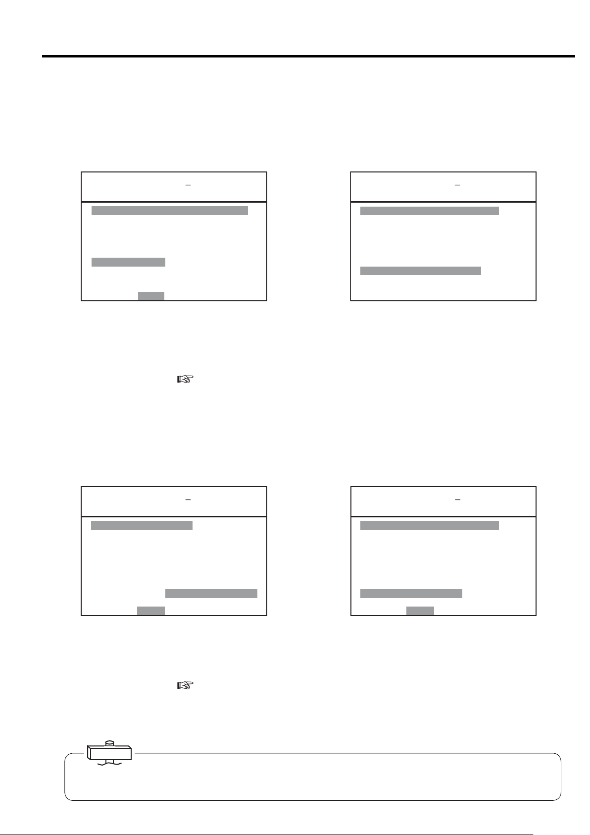
3.3.3 Message Displays
■ Shutdown Messages
① When a shutdown occurs for the compressor, the SHUTDOWN light and shutdown contents on the LCD monitor
(contents are displays on the left side and details are displayed on the right side) flash and the compressor stops running. There are 2 types of screens for shutdown: SHUTDOWN and FAILURE.
㻞㻜㻜㻣䠋㻜㻤䠋㻜㻝 㻝㻥䠖㻝㻥 㻖
㼀㼅㻼㻱 䠖 㼂㻿㻰㻭
㻰 㻵 㻿䠊㻼㻾㻱 㻿㻿 䠖 㻌 㻌 㻢 㻣㼜 㼟 㼕
䠘㻿 㻴 㼁 㼀 㻰 㻻 㼃 㻺䠚
㻯㻻㻻㻸㻭㻺 㼀 䠖
㻻㻵 㻸䠖
㻞䠪㻰 㻌 㻿㼁㻯㼀䠊㼀㻱㻹㻼
㻴㻵㻳㻴 㻌㻰㻵㻿䠊㼀㻱㻹㻼䠖
㻯 㻻 㻺 㼀 㻭 㻯 㼀 㻻 㻾 㻌㻱 㻾 㻾 䠖
㻻㼂㻱 㻾㻸 㻻㻭㻰 䠖
㻸㻻㼃 㻌 㼃 䠊 㻵 㻺㼀 㻿 㼀㻳 㻌 㻼䠊
㻰 㻾 㼅 㻱 㻾 㻌㻌㻌㻌 㼃 䠋 㻻 㻌 㻿 㻱 㻼 䠊
㻱㻸㻱㻹㻱 㻺㼀
㻼 㼞 㼑 㼟 㼟 㻾㻱 㻿 㻌 㼍 㼒 㼠 㼑 㼞 㻌 㻯㻴㻷䠊
㼀㼁
㻌
(Example)
In the case the thermal relay trips and the compressor stops
running, SHUTDOWN and OVERLOAD flash and the malfunction part of the main circuit is indicated.
㻞㻜㻜㻥䠋㻜㻤䠋㻜㻝 㻝㻥䠖㻝㻥 㻖
㼀㼅㻼㻱 䠖 㼂㻿㻰㻭㻌
㻰 㻵 㻿 䠊 㻼㻾 㻱 㻿 㻿 䠖 䚷䚷 㻢 㻣 㼜 㼟 㼕
䠘㻲 㻭 㻵 㻸 㼁 㻾 㻱䠚
㻿 㼅 㻿 㼀 㻱 㻹 㻱 㻾㻾 䠖 㼙㼙㼙㼙
㻿㼅㻿㼀㻱㻹 㻌 㻾㻱㼀㻾㼅
㻼㻯㻮㻌㻱㻾㻾䠖 㼚㼚㼚㼚㼚㼚
㻼㻾㻱㻿㻿䠊㻿㻺㻿㻾㻌 㻱㻾㻾䠖 㼛
㼀㻱㻹㻼䠊㻿㻺㻿㻾 㻱㻾㻾䠖 㼜
㻰䡅 㼟㼏㼛㼚㼚㼑㼏㼠 㼜㼛㼣㼑㼞
㼟㼚㼐 㼏㼛㼚㼠 㼍㼏 㼠
㼐 㼕 㼟 㼠 㼞 䡅㼎㼡 㼠㼛 㼞
㻌㻌 㻌㻌㻌
(Example)
Example of temperature sensor malfunction, sensor 1 disconnection FAILURE and TEMPERATURE SENSOR flash and
the location of the abnormality is indicated.
② Take the proper corrective action, and press the RESET button.
③ For further information,
see pages 33, 34.
NOTE) Malfunction detection of water failure is available for only water cooled single stage compressor. Malfunction
detection of dryer is available for only built-in dryer models. Malfunction detection of oil water separator and
element is not available.
■ Alarm Messages
① In the case an alarm occurs for the compressor, the ALARM light and contents / details displayed on alarm screen on
the LCD monitor flash and operation continues. There are 2 types of alarm screens: ALARM andPROBLEM.
㻞㻜㻜㻥䠋㻜㻤䠋㻜㻝 㻝㻥䠖㻝㻥 㻖
㼀㼅㻼㻱 䠖
㻰 㻵 㻿 䠊 㻼㻾 㻱 㻿 㻿 䠖 䚷䚷 㻢 㻣 㼜 㼟 㼕
䠘㻭 㻸 㻭 㻾 㻹䠚
㻰㻵 㻿䠊㼀㻱㻹㻼䠖䠄㻌 㻌 㻌 䠅㻖㻖㻖䉣
㻻㻵 㻸㻌 㼀㻱㻹㻼䠖 㻖㻖㻖䉣
㻸㻻㼃 㻌㻻䠊㻼䠊䠖 㻖䠊㻖 㻖㼜 㼟 㼕
㻯㻸㼀䠊㼀㻱㻹㻼䠊䠖 㻖㻖 㻖䉣
㻸㻻㼃 㻌 㻯㻸 㼀䠊 㻼 䠖 㻖 䠊 㻖 㻖 㼜 㼟 㼕
㻞䠪㻰 㻙 㻿䠊 㼀 㻱㻹㻼 㻌 㻲 㻵 㻺 㻙 㼀
㻸㻻㼃 㻌 㼃 䠊 㻸㻻㼃 㻌 㻻 㻵 㻸
㻰㻾㼅㻱㻾 㻭 㻵㻾 㻌㻲 㻵 㻸㼀㻱㻾
㻸䠊㻯㻻㼁㻺㼀 㻌 㻻㼂㻱 㻾 㻌㼃䠋㻻 㻌 㻿䠊
㻼㼞㼑㼟䡏㻾㻱㻿 㼍㼒㼠㼑㼞㻌㻯㻴㻷䠊
㻿㻰㻭㻌 㻌㻌 㻌㻌㻌
㼂
(Example)
In the case ALARM and AIR FILTER flash while the com-
㻞㻜㻜㻥䠋㻜㻤䠋㻜㻝 㻝㻥䠖㻝㻥 㻖
㼀㼅㻼㻱 䠖 㼂㻿㻰㻭㻌
㻰 㻵 㻿 䠊 㻼㻾 㻱 㻿 㻿 䠖 䚷䚷 㻢 㻣 㼜 㼟 㼕
䠘㻼 㻾 㻻 㻮 㻸 㻱 㻹䠚
㻯㻻㻺㻺㻱㻯 㼀 㻵 㻻㻺 㻌 㻱㻾㻾䠖 㻌 㻌 㻌
㻾㼑㼏㼛㼚㼚㼑㼏㼠 㻌 㼜㼛㼣㼑㼞䠊
㻹㼁㻸㼀䠥 㻙㼁 㻿㻱㼀 㻱㻾㻾
㻿㻯㻴㻱㻰㼁㻸㻱 㻌 㻿㻱 㼀 㻌 㻱㻾㻾
㻯㻻㻹䠊㻱㻾㻾㻌㻿㼀㻻㻼䠖㻌㻌㻌㻌㻌
㻯㻻㻹䠊㻱㻾㻾㻌㻭㻸㻹䠖 㻌㻌㻌㻌㻌
㻮㻭㼀㼀㻱㻾㼅 㻌㻻㼁㼀
㻼 㼞 㼑 㼟 㼟 㻾㻱 㻿 㼍 㼒 㼠 㼑 㼞 㻯 㻴㻷䠊
㻌㻌 㻌㻌㻌
(Example)
Example of battery replacement period.
pressor is running, it indicates the filter is clogged.
② Take the proper corrective action, and press the RESET button.
③ For further information,
see pages 33, 34.
NOTE) Malfunction detection of water failure is available for only water cooled single stage compressor. Malfunction
detection of dryer is available for only built-in dryer models. Malfunction detection of oil water separator and
element is not available.
IMPORTANT
ALARM and PROBLEM messages are treated as alarms, but aside from connection abnormalities that make operation impossible such as reverse phase and no phase when power is turned on, they also may indicate shutdown due to malfunction of the
communication status.
15

3. OPERATING THE DSP [How to Use the Liquid Crystal Display (LCD)]
■ Messages of Automatic Stop Display and Automatic Restart Display
When the DSP air compressor has automatically stopped, the following screen is displayed, the AUTO START light
flashes/lights, and the RESTART message screen and details of contents flash on the LCD monitor.
● SCHEDULED STOP: Schedule operation setting
<AUTO light ON>
When schedule is set on the scheduled operation
㻞㻜㻜㻥䠋㻜㻤䠋㻜㻝 㻝㻥䠖㻜㻞 㻖
㼀㼅㻼㻱 䠖 㼂㻿㻰㻭㻌
㻰 㻵 㻿䠊 㻼㻾 㻱 㻿 㻿 䠖 䚷䚷 㻢 㻣 㼜 㼟 㼕
䠘㻾㻱㻿㼀㻭㻾㼀䠚
㻾 㻱 㻿 㼀 㻭 㻾 㼀 㻭 㼀 䠖 䠆䠆 䠖 䠆䠆
㻾㻱㻿㼀㻭㻾㼀 㼃㻭 㻵 㼀䠖 㻌 㻞㻣䡏
㻺㻻㼃䠈 㻿 㼀 㻻 㻼 㻼 㻱 㻰 䠞䠵 䠖
㻿㻯㻴㻱㻰㼁㻸㻱 㻿㼀㻻㻼
㻭㼁㼀㻻㻹㻭㼀 㻵 㻯 㻿 㼀㻻㻼
㻰㻾㼅㻱㻾 㻼㻾㻱㻿㼀㻭㻾㼀㻱㻰
㻰㼁㻭㻸䠋㻮㻭㻯㻷㼁㻼
㻵 㻼 㻵 㻌 㻾㻱㻿㼀㻭㻾㼀
㻯㼀㻸㻾䠊㻾㻱㼀㻾㼅
㻌㻌 㻌㻌㻌
screen, displays state of operation being stopped by
preset time. Operation starts automatically when the
preset restart time comes.
● LEAD/LAG OPERATION STOP
(Note: applies only to machines equipped with two-
unit alternate operation.)
<AUTO light ON>
When the operation control mode is set to dual or
backup on the operation mode setting screen, standby
status of the slave machine in dual or backup operation
is indicated.
● DRYER PRESTARTED
(Note: Applies only to machines equipped with a
built-in dryer.)
<AUTO START light flashes>
When dryer prestart is set, the dryer starts operating
in advance, and compressor stopped status is indicated.
RESTART WAIT time is counted down.
● AUTO OPERATION
(Note: Applies only to machines equipped with
AUTO function)
<AUTO START light ON>
Indicates status stopped by low load when set to
AUTO operation. AUTO START light flashes during
restart limit while stopped, and RESTART WAIT time
is counted down.
● INSTANT STOP / RETRY
(Note: Retry applies to V type only.)
<AUTO START light flashes>
Displays status of restart for instantaneous power
interruption (IPI) restart and V type retry.
RESTART WAIT time is counted down.
16
3. OPERATING THE DSP [How to Use the Liquid Crystal Display (LCD)]
■ Maintenance Notice Messages
A maintenance date is determined by the amount of total operating hours or an elapsed calendar period, whichever
comes first. When the maintenance date or time arrives, the maintenance notice message appears on the display under
the heading of MAINTenance.
This function is an alarm display only, and does not output alarm externally.
Replace suction throttle valve consumable parts when inspection maintenance is displayed or the 1 million unloader
count alarm is given, whichever comes first.
㻞㻜㻜㻥䠋㻜㻤䠋㻜㻝 㻝㻥䠖㻜㻞 㻖
㼀㼅㻼㻱 䠖 㼂㻿㻰㻭㻌
㻰 㻵 㻿䠊㻼㻾㻱 㻿㻿 䠖 㻌 㻌 㻢 㻣 㼜 㼟 㼕
䠘㻹㻱㻿㻿㻭㻳㻱䠚
㻹㻭 㻵 㻺 㼀䠊 䠖㻝 㼅㻱 㻭 㻾㻌 㻌
㻹㻭 㻵 㻺㼀 䠊䠯䠟䠤䠡䠠䠱 㻸 䠡 䠖 㻭
㻼 㼞 㼑 㼟 㼟㻿㻱 㼀 㻌 㼍 㼒 㼠 㼑 㼞 㻌 㻯㻴㻷䠊
㻹㻭 㻵 㻺 㼀䠊㻯㻻㻹㻼 㻸 㻱 㼀㻱 㻰
㻿㼃 㻵 㼀㻯㻴㻱㻰 㻌 㼀㻻 㻌 㻸㻻㻯㻭㻸
㻵 㻺 㻌 㻻㼂㻱㻾䠮㻵 㻰㻱 㻹㻻㻰㻱
㻵㻺㻌㼁㻺㻸㻻㻭㻰㻌㻿㼀㻻㻼
㻿㼃 㻵 㼀 㻯㻴 㻱 㻰 㻌 㼁 㻌 㻹㻻㻰 㻱
㻌㻌 㻌㻌㻌
(1)
(2)
(3)
Every these calendar periods: Service the DSP according to the schedules:
0.5 years, 1.5 years, 2.5 years
3.5 years, 4.5 years, 5.5 years
1.0 years, 5.0 years Yearly + Half-Yearly
2.0 years, 4.0 years 2-Yearly + Yearly + Half-Yearly
3.0 years 3-Yearly + Yearly + Half-Yearly
6.0 years (for overhauling)
Standard Maintenance Schedule (A) (for yearly 8,000-or-less operating hours)
A
Standard Maintenance Schedule (B) (for yearly 4,000-or-less operating hours)
B
Half-Yearly
6-Yearly + 3-Yearly + 2-Yearly + Yearly + Half-Yearly
CAUTION
If the inspection/maintenance is displayed, check the display contents, refer to maintenance standards
given in the compressor instruction manual and perform inspection/maintenance as soon as possible.
When inspection is complete, press and hold the SET button for at least 7 seconds.
The LCD monitor display contents then move to “Maintenance initial value completed” of the message
screen, and then return to the monitor screen 1 minute later.
NOTES:
1. MAINTenance can be reset, if the servicing is done earlier than expected and if the remaining operating time to next maintenance
is less than 2,000h in the case of A, 1,000h in the case of B.
2. On the contrary, if the servicing is done after the maintenance notice has appeared, the remaining operating hours to the next maintenance has been zero until the maintenance is done. After maintenance and resetting the counter, new counting time starts just
after the maintenance notice message has appeared on the display.
■ Other Messages
(1)SWITCHED TO LOCAL.
If set to local by remote operation following shut-
down restoration, operation automatically returns
to local when shutdown occurs, and the message is
displayed for 1 minute. For setting details, see
“3.4 How to Use the Digital Monitor.”
(
page 25)
(2) IN OVERRIDE MODE.
This message blinks when the DSP is in an over-
ride mode.
(3) UNLOAD STOP
If the UNLOAD STOP button is used, the display
flashes. The compressor unloads for 5 minutes and
then stops.
17
3. OPERATING THE DSP [How to Use the Liquid Crystal Display (LCD)]
3.3.4 How to Move within a Menu Display and to Change a Setting
ー [FUNCTION MENU] and [MAINTenance DATA MENU] ー
The method and procedure for altering settings is displayed using the following as an example.
How to Move within a [FUNCTION MENU] Display
1
㼇 㻲 㼁㻺㻯㼀 㻵 㻻㻺 㻹㻱㻺㼁 㼉
㻝䠊㻮㻭㻿 㻵 㻯㻌 㻿㻱 㼀㼁㻼
㻞 䠊㻹㼁 㻸 㼀 㻵 㻙 㼁㻺 㻵 㼀
㻟䠊㻯㻭㻼㻭㻯 㻵 㼀㼅 㻯㻻㻺㼀㻾㻻㻸
㻠䠊㻿㻯㻴㻱㻰㼁㻸 㻱
㻡䠊㻻㻼 㻱㻾 㻭㼀 㻵 㻻㻺 㻰 㻭㼀 㻭
㻢䠊㻸㻻㻭㻰 㻰㻭㼀㻭
㻣䠊㻭㻸㻭㻾㻹 㻴 㻵 㻿㼀㻻㻾㼅
㻤 䠊 㻿 㻴㼁㼀㻰㻻㼃㻺 㻴 㻵 㻿㼀 㻻㻾 㼅
1 – 2.
② Select the number of the item to be set with the
▽
△
③ Enter with the SET button. The display then switches
to the detail setting screen for that item.
The following explanation uses [2. Operation Mode
Setting Screen] as an example.
① Press the MENU button displayed on monitor screen
㻿㻱 㼀 䠖 㻻㻼㻱 㻺 㻹㻻㻺䠖 㻮㻭㻯㻷
How to Select or Change a Setting within a Setting Display
2
① When the display switches to the details screen, move
㼇㻹㼁㻸㼀 㻵 㻙㼁 㻌 㻿㻱㼀㼀 㻵 㻺㻳㼉
㻝
㻹㻻㻰 㻱 䠖 㻳㻸
㻞䠊㻰㼁㻭㻸㻌 㼀 㻵 㻹㻱䠖 㻌 㻤䠊
㻟䠊㻹㻱㼀㻴㻻㻰 䠖 㻭㻼
㻠䠊㻿㼃 㻵 㼀㻯㻴㻻㼂㻱㻾䠖 㻜 㻝 㻡 㼟
㻡䠊㻮㻭㻯㻷㼁㻼 䠖 䚷䚷䚷㻣㼜
㻢䠊㼁 㻺㻸㻻㻭㻰䠖 䚷䚷䚷㻟 㼜㼟 㼕
㻭㻸㼀䠊㼀㻵㻹㻱䠖㻌 㻠㻤㻜㻹㻵㻺
㻣
㻯㻻㻺㼀 㻾㻻 㻸 㻹㻻㻰 㻱 䠖 㻮
㻤
㻌 㻿㻺
㻜㼔
㻻㼂㻾 㻾㻸
㼟㼕
to the line to be altered with the
tons.
IMPORTANT
Items with a dash next to their number cannot be altered
on the LCD monitor. In this case, alter from the digital
monitor while referring to the instructions manual for the
compressor.
buttons.
△
▽
but-
㻿㻱㼀䠖㻿㼀㻻㻾㻱 㻌㻹㻻㻺䠖㻮㻭㻯㻷
①
㻝 㻹㻻㻰 㻱 䠖
㻞䠊㻰㼁㻭㻸㻌 㼀 㻵 㻹㻱䠖 㻌 㻤䠊㻜 㼔
㻟䠊㻹㻱㼀㻴㻻㻰 䠖
㻠䠊㻿㼃 㻵 㼀㻯㻴㻻㼂㻱㻾䠖 㻜 㻝 㻡 㼟
㻳㻸㻿㻺
㻭㻼㻻㼂㻾 㻾㻸
②
㻝 㻹㻻㻰 㻱 䠖
㻞䠊㻰㼁㻭㻸㻌 㼀 㻵 㻹㻱䠖 㻌 㻤䠊㻜 㼔
㻟䠊㻹㻱㼀㻴㻻㻰 䠖
㻠䠊㻿㼃 㻵 㼀㻯㻴㻻㼂㻱㻾䠖 㻜 㻝 㻡 㼟
㻳㻸㻿㻺
㻭㻼㻻㼂㻾 㻾㻸
③
㻝 㻹㻻㻰 㻱 䠖
㻞䠊㻰㼁㻭㻸㻌 㼀 㻵 㻹㻱䠖 㻌 㻡䠊㻜 㼔
㻟䠊㻹㻱㼀㻴㻻㻰 䠖
㻠䠊㻿㼃 㻵 㼀㻯㻴㻻㼂㻱㻾䠖 㻜 㻝 㻡 㼟
㻳㻸㻿㻺
㻭㻼㻻㼂㻾 㻾㻸
④
㻹㻻㻰 㻱 䠖
㻝
㻞䠊㻰㼁㻭㻸㻌 㼀 㻵 㻹㻱䠖 㻌 㻡䠊㻜 㼔
㻟䠊㻹㻱㼀㻴㻻㻰 䠖
㻠䠊㻿㼃 㻵 㼀㻯㻴㻻㼂㻱㻾䠖 㻜 㻝 㻡 㼟
㻳㻸㻿㻺
㻭㻼㻻㼂㻾 㻾㻸
Move to the item to be altered with the
②
▽
③
Alter the setting value with the
△
④ After altering the setting value, press the SET button.
The cursor moves to the number.
⑤ Press the SET button again.
The cursor moves to the first number at the top of the
screen and the setting contents are entered.
When setting is complete, pressing the MONITOR button once returns the display to the MENU screen, and
pressing it again returns to MONITOR screen 1.
The same procedure is used to alter settings for other
menus.
IMPORTANT
When altering settings of the LCD screen, number update
by button operation is slow. Press the buttons slowly
when altering settings.
⑤
㻝 㻹㻻㻰 㻱 䠖
㻞䠊㻰㼁㻭㻸㻌 㼀 㻵 㻹㻱䠖 㻌 㻡䠊㻜 㼔
㻟䠊㻹㻱㼀㻴㻻㻰 䠖
㻠䠊㻿㼃 㻵 㼀㻯㻴㻻㼂㻱㻾䠖 㻜 㻝 㻡 㼟
㻳㻸㻿㻺
㻭㻼㻻㼂㻾 㻾㻸
button.
▽
buttons.
18
3. OPERATING THE DSP [How to Use the Liquid Crystal Display (LCD)]
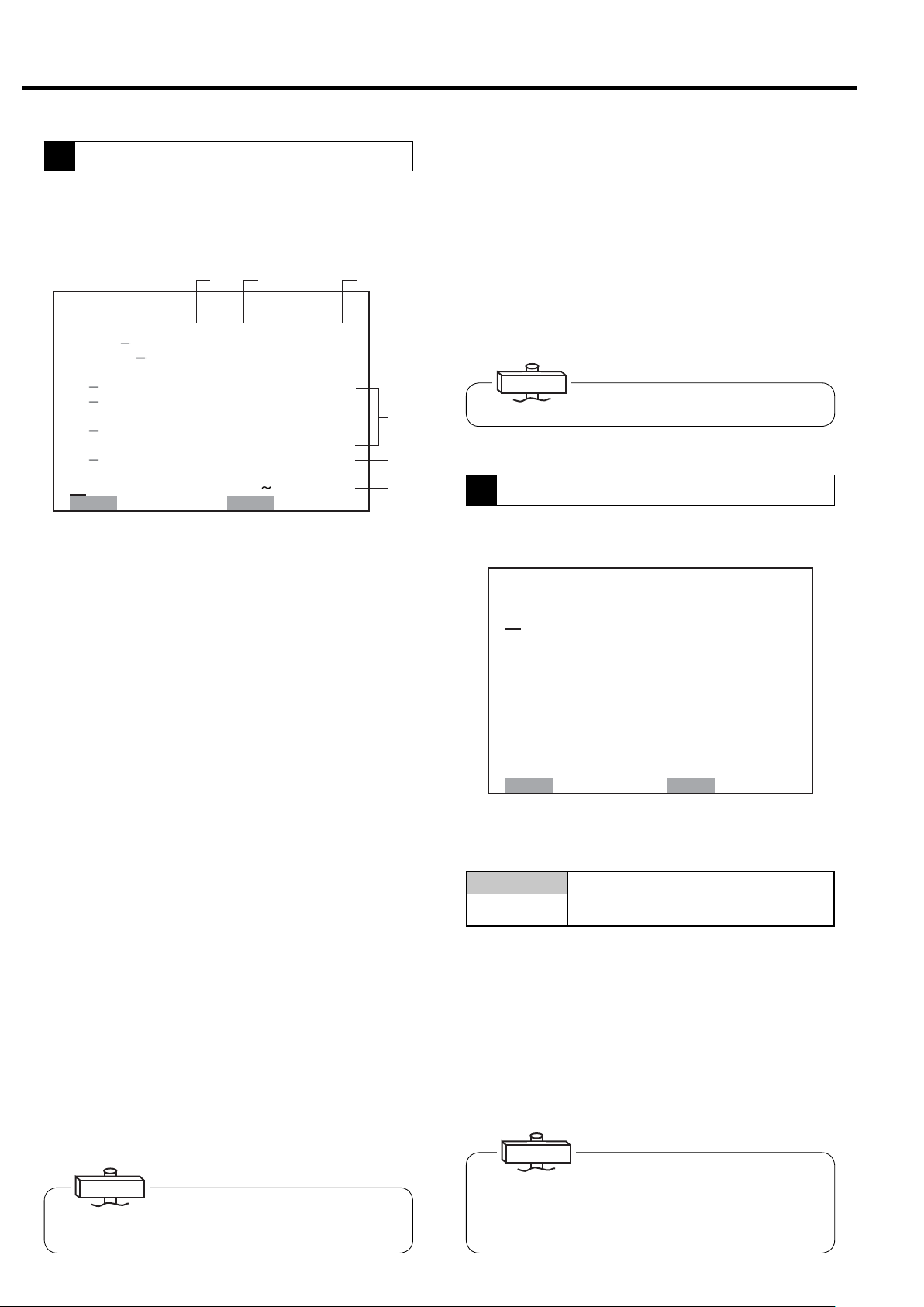
3.3.5 [FUNCTION MENU] −Setting Displays
Model Setting Confirmation
1
㼇㻮㻭㻿㻵㻯 㻿㻱㼀㼁㻼㼉
㼂㻱㻾䠊䠖 㻡䠊㻜
㻿㻱㻾 㻵 㻱㻿 㻺㻭㻹㻱䠖 㻰㻿㻼
㻯㻻㻻㻸 㻵 㻺㻳 㻹㻱 㼀㻴㻻㻰䠖 㼃㼀㻾
㻺㻻䠊㻻㻲 㻿 㼀㻭 㻳㻱 䠖 㻌 㻞
㻼㻙㻿㻼㻱㻯䠖 䚷㻝 㻜㻜㼜㼟㼕
㻼 䠊 㻰 㻭 㼀 㻭 䠖 䚷䚷 㻢 㻤 㼜 㼟 㼕
䠟䠰䠖 㻞㻡㻜䠝
㻯㻸 㼀䠊㻰 㻱 㻸 㻭㼅 䠖 㻌 㻡 㼟
㻵㻼㻵䠖 㻵㻵㻵
㻭㻰㻾 㻱 㻿 㻿 㻺㻻䠊 䠖 㻌 㻝
㻹㻻㻺 䠖 㻮㻭㻯㻷
IMPORTANT
The screen provides the model and serves as a target for
setting status. Check the screen when making an inquiry.
㻡䠊㻜
①
②
③
④
⑤
⑥
⑦
⑧
⑨
⑩
The starter of settings can be confirm the software,
model and setting status of model-specific settings such
as capacity control. (Double asterisks are displayed for
settings that do not require confirmation.)
① Indicates board software version.
② Indicates compressor type.
③ Displays cooling type.
④ Displays the number of compressor stages.
⑤ Displays pressure specification.
⑥ Displays interstage pressure.
⑦ Indicates CT setting value.
⑧ Displays water failure detection conditions for water
cooled compressor.
⑨ Displays status of instantaneous power interruption
(IPI) restart setting.
Displays compressor number. (Must be distinguished by
⑩
number is using communication function.)
Operation Mode Settings
2
Confirm settings by compressor alternate operation
specifications and multiple unit control (communication
support). Wiring must be supplied separately for use.
Items for which a dash is displayed next to their number cannot be set on the LCD monitor.
㼇㻹㼁㻸㼀 㻵 㻙㼁 㻌 㻿㻱㼀㼀 㻵 㻺㻳㼉
㻝
㻹㻻㻰 㻱 䠖 㻳㻸
㻞䠊㻰㼁㻭㻸㻌 㼀 㻵 㻹㻱䠖 㻌 㻤䠊
㻟䠊㻹㻱㼀㻴㻻㻰 䠖 㻭㻼
㻠䠊㻿㼃 㻵 㼀㻯㻴㻻㼂㻱㻾䠖 㻜 㻝 㻡 㼟
㻡䠊㻮㻭㻯㻷㼁㻼 䠖 㻌 㻌 㻌 㻣㼜
㻢䠊㼁 㻺㻸㻻㻭㻰䠖 㻌 㻌 㻌 㻟㼜 㼟 㼕
㻭㻸㼀䠊㼀㻵㻹㻱䠖㻌 㻠㻤㻜㻹㻵㻺
㻣
㻯㻻㻺㼀 㻾㻻 㻸 㻹㻻㻰 㻱 䠖 㻮
㻤
㻿㻱㼀䠖㻿㼀㻻㻾㻱 㻌㻹㻻㻺䠖㻮㻭㻯㻷
㻌 㻿㻺
㻜㼔
㻻㼂㻾 㻾㻸
㼟㼕
1. Operation control: Set operation control is dis-
played on the digital monitor.
IMPORTANT
If using the backup function, switch to the digital monitor and set.
2. LEAD/LAG operation time: Time setting for alter-
nate operation of a pair of compressors (setting
range: 0.1 – 99.9 hours; initial value: 8.0)
3. Switching conditions: Setting of conditions for
switching operation between a pair of compressors
4. Switching time: Switching time setting if switch-
ing conditions are “parallel” or “interval” (setting
range: 5 – 300 seconds, initial value: 15)
Single Operates compressor independently.
Case where multiple unit control is executed by communication
STPR
Multiple
()
Backup
OVER LAP
Interval
function of multi roller EX (dedicated panel of NEXT Series).
Unit control is executed by RS485 communication according to
unit
the settings. Requires separate setting of compressor number.
Operation alternates between a pair of compressors for
Dual
a preset amount of time. AUTO light lights.
Operation mode that adds pressure backup function to
dual operation. When pressure drops, the slave machine
starts. AUTO light lights.
Method whereby first compressor is stopped after switching time for
the other unit in parallel operation when it is time for dual operation.
Method of operating the other compressor after stopping the
first one after switching time when it is time for dual operation.
5. BACKUP: Setting of pressure to start the backup
compressor when set to backup operation (range: 0.00
– 72 psi, initial value: 7, difference from recovery pressure in the minus direction).
6. UNLOAD:
Pressure setting that manually unloads 1 unit
when the preset pressure is reached in backup operation
(range: 0.00 – 72 psi, initial value: 3, difference from control pressure in the minus direction).
7. DUAL TIME:
Displays time remaining until switch for
dual / backup operation. Time is not counted down
when operating 2 units for backup operation. When
operation is stopped, remaining time is maintained.
8.
SPEED CONTROL MODE: Displays control mode of V
type. An asterisk is displayed for the Fixed speed type.
IMPORTANT
Altered setting values can only be entered when the compressor is not running.
19
3. OPERATING THE DSP [How to Use the Liquid Crystal Display (LCD)]
Capacity CONTROL SETTING Display
3
Screen for confirming pressure settings for capacity control. Pressure settings are set from the digital monitor.
Pressure settings consist of setting 1 and setting 2,
which can be used by setting time used.
①② ③
㼇 㻯㻻㻺 㼀㻾㻻㻸 㻿 㻱 㼀 㼀 㻵 㻺㻳 㼉
㻝䠊㼀㼅㻼㻱䠖㼂㻭 㼎㼎㼎 㼏㼏㼏
㻞䠊䠬
㻟䠊䠬 㻵
㻠
㻡
㻢
㻣
㻤䠊㼀 㻵㻹㻱䠖㻝㻤䠖㻜㻜
㻿㻱㼀䠖㻿㼀㻻㻾㻱 㻌㻹㻻㻺䠖㻮㻭㻯㻷
㻸㻻㻿㻿 䠖 㻖 䠊 㻖 㻖 㼜 㼟 㼕
㻯㻭䠖㻖㻖㻖 㻖㻖䠊㻖䡉㻟
䠄㻯㻻㻺㼀㻾㻻㻸䠋㻯㼁㼀㻙 㻵 㻺 㻕
㻼㻝䠖 㻌 㻝 㻜㻜䠋㻌 㻌 㻤㻣㼜㼟 㼕
㻼㻞䠖 㻌 㻝 㻜㻜䠋㻌 㻌 㻤㻣㼜㼟 㼕
䠄㼀㻭㻾㻳㻱㼀㻌 㻼㻝䠋㻼㻞 㻕
㼀㻭㻾㻳㻱 㼀 䠖
㻌㻌 㻥㻤䠋㻌㻌 㻥㻤㼜㼟㼕
㼀㻵㻹㻱㻌㻸 㻵㻹㻵 㼀䠖 㻜㻟㻜㼟
䠄㻼 㻞 㻱 㻲㻲㻱㻯㼀 㻵 㼂㻱 㻕
㻞㻞䠖㻜㻜
④
⑤
⑥
1. TYPE: Displays setting data for capacity control.
① Control settings set by the digital monitor can be con-
firmed.
Fixed speed type: I (load/unload operation) / IP (AUTO
operation specifications * optional)
V type: VB (AUTO function off)/ VA (AUTO operation
specifications)
② Setting type of pressure set by the digital monitor can
be confirmed.
SETTING 1: Standard pressure setting;
SETTING 2: 2nd pressure setting
EXT: External load/unload setting
AUTO: Switches setting 1 and setting 2 by time.
③ Sets optional conditions. With standard specifications,
displays “ordinary” characters.
2 - 3. OPTION: Used for options.
4 - 6. PRESSURE SETTING: Pressure settings set by
the digital monitor, target pressure and time limit can be
confirmed all at once on the LCD monitor. ④
7. TIME LIMIT: (Fixed speed type only)
Preset time limit can be confirmed.
The time limit is effective when ECOMODE (energy
conservation mode) is selected by pressing and holding
the DISPLAY SWITCH button for at least 7 seconds.
The function sets energy conservation mode until control pressure (unload start pressure) drops to the target
value if the load and unload repeat time clears the time
limit. If control pressure and recovery pressure change
time is measured and it exceeds the time limit, control
pressure is lowered so the time limit is no longer
exceeded. ⑤
(Time limit range: 30 - 120 seconds; initial value: 30 seconds)
8. USE TIME: Sets time to use pressure of setting 2. At
that time, it displays automatic at the position of (2) of
the type. When start and stop time become the same
value, the automatic display is returned to setting 1 and
the function is stopped.
IMPORTANT
Settings are selectable when the DSP is in a stop.
Schedule Setting
4
Scheduled operation can be set for 1 day (standard equipment).
㼇 㻿㻯㻴㻱㻰㼁㻸㻱 㻌 㻿 㻱 㼀㼀 㻵 㻺㻳 㼉
㻝䠊㻹㻻㻰㻱 䠖 㻯㻴㻱㻰㼁㻸 㻱
㻿㼀㻭㻾㼀 㻿㼀㻿㻻㻼
䠄㻝䠅㻜㻣䠖㻜㻜㻌 㼅 㻞㻜䠖㻜㻜 㻌 㼅
䠄㻞䠅㻜㻜䠖㻜㻜㻌 㻺 㻜㻜䠖㻜㻜 㻌 㻺
䠄㻟䠅㻜㻜䠖㻜㻜㻌 㻺 㻜㻜䠖㻜㻜 㻌 㻺
䠄㻠䠅㻜㻜䠖㻜㻜㻌 㻺 㻜㻜䠖㻜㻜 㻌 㻺
䠄㻡䠅㻜㻜䠖㻜㻜㻌 㻺 㻜㻜䠖㻜㻜 㻌 㻺
㻞䠊㻾㻱㻯㻻㻾㻰 㻝䠖 㻝㻜䠖㻜㻜
㻟䠊㻾㻱㻯㻻㻾㻰 㻞䠖 㻝㻥䠖㻜㻜
㻿㻱㼀䠖㻿㼀㻻㻾㻱 㻌㻹㻻㻺䠖㻮㻭㻯㻷
The display shows an example setting of scheduled operation from 7:00 to 20:00. “19:07” indicates the current time
㻝㻥䠖㻜㻣
1. MODE: Scheduling Mode
OFF
SCHEDULED
Operates the DSP without a schedule.
Operates the DSP according to a daily 24hour calendar.
1. to 5. : Five Start/Stop Time Patterns
・ START: Starting Time
・ STOP: Stopping Time
・ Y or N :Yes starts or stops as scheduled.
2. DATA MEASUREMENT TIME: Time for recording
operation data twice a day can be set.
Recorded operation data can be confirmed by the “5”
operation data record screen.
IMPORTANT
IMPORTANT
If the time limit is altered, consult with your dealer or the
Hitachi Service Station given on the rear cover.
20
If “SCHEDULE” is set, the AUTO light lights. If there is no
valid setting for time, the AUTO light flashes. Altered setting can only be entered when the compressor is not running.
3. OPERATING THE DSP [How to Use the Liquid Crystal Display (LCD)]
Operation Data Display
5
㼇 㻻㻼㻱 㻾㻭㼀 㻵 㻻㻺 㻰 㻭㼀 㻭 㼉
㻝䠊㻜㻤䠋㻜㻝 㻝㻜䠖㻜㻜
㻼䠖㻌 㻢㻣䚸㻌 㻢㻤䚸㻖㻖㻖䚸㻖㻖㻖
㻯䠖 㻜
㼀䠖 㻣㻣䚸 㻥㻝䚸㻖㻖䚸㻖㻖䚸㻖㻖
㻸䠖 㻡 㻥䚸㻝 㻤䠊㻤
㻞䠊㼍㼍䠋㼎㼎 㼏㼏䠖㼐㼐
㻼䠖㻖㻖㻖䚸㻖㻖㻖䚸㻖㻖㻖䚸㻖㻖㻖
㻯䠖㻖㻖㻖
㼀䠖㻖㻖㻖䚸㻖㻖㻖䚸㻖㻖䚸㻖㻖䚸㻖㻖
㻸䠖㻖㻖㻖䚸㻖㻖㻖㻖㻖
㻹㻻㻺 䠖 㻮㻭 㻯㻷
Records date/time, pressure, current, temperature and
load status at that time as operating state recorded by
data measurement time. Up to 12 times can be recorded,
after which the oldest data is deleted one at a time; the
latest data is displayed for item 1. The screen shows
record for 2 times, and the necessary data can be con-
▽
firmed by
△
button operation. If altered before
time is up, the data prior to change is maintained, and the
time recorded as soon as the data is altered changes.
1. and 2. - :Indicates the MONTH / DAY HOUR: MINUTE.
P - Represents a pressure (psi) and indicates, from left to
right, the: Discharge air pressure, pressure data.
C - Current (A).
T - Represents a temperature (℉)and indicates from
left to right: 1st stage discharge air temperature, 2nd
stage discharge air temperature.
L -
Represents a load ratio percentage (%). and out put (kW).
If there is no data, an asterisk is displayed.
Alarm History
7
If an alarm occurs on the digital monitor, shutdown history is recorded. Up to 6 items of alarm history however
can be recorded aside from shutdown history. Contents
and occurrence state can be confirmed.
㼇 㻭 㻸 㻭 㻾㻹 㻴 㻵 㻿 㼀㻻㻾 㼅 㼉
㻝䠊 㼍㼍㼍㼍㼍㼍㼍㼍㼍㼍㼍㼍㼍
㻯㻻㻰㻱䠖㻞㻝㻸 㻺㻻㻿䠊䠖㻌 㻝
㻜㻣䠋㻜㻤䠋㻜㻝 㻝㻥䠖 㻞㻢
㻞䠊 㻖㻖㻖㻖㻖㻖㻖㻖㻖㻖㻖㻖㻖
㻯㻻㻰㻱䠖㻖㻖㻖 㻺㻻㻿䠊䠖㻖㻖
㻖㻖䠋㻖㻖䠋㻖㻖 㻖㻖䠖 㻖㻖
㻟䠊 㻖㻖㻖㻖㻖㻖㻖㻖㻖㻖㻖㻖㻖
㻯㻻㻰㻱䠖㻖㻖㻖 㻺㻻㻿䠊䠖㻖㻖
㻖㻖䠋㻖㻖䠋㻖㻖 㻖㻖䠖 㻖㻖
㻹㻻㻺 䠖 㻮㻭㻯㻷
①
① Operation state is indicated by a symbol next to the
shutdown code.
L: Load, U: Unload, S: Stop
Displays alarm contents and code, date, time, state and
how many times alarm occurred. If the same alarm continues to occur, it is overwritten as update data, and the
number of times the alarm occurs is updated. The latest
warning is recorded as item 1. If there is no alarm, asterisks are displayed. The screen displays data for 3 types,
▽
and the necessary data can be confirmed by
△
button operation.
Shutdown History Display
8
Load Data Display
6
㼇 㻸㻻㻭㻰 㻰㻭㼀㻭 㼉
㻝䠊㻜㻤䠋㻜㻝
㻭㼂㻳䠊㻼㻾 㻱 㻿㻿 䠖 㻌 㻌 㻣 㻡 㼜 㼟 㼕
㻭㼂㻳䠊㻯㼁㻾㻾㻱㻺㼀䠖 㻜㻠㻜䠝
㻭㼂㻳䠊㻸㻻㻭㻰 㻾㻭㼀㻱䠖㻜㻢㻡䠂
㻭 㼂 㻳 䠊 㻼 䠫䠳 䠡 䠮 䠖 㻌 㻝 㻣 㻚 㻤 㼗 㼃
㻞䠊㻜㻝䠋㻜㻝
㻭㼂㻳䠊㻼㻾 㻱 㻿㻿 䠖 㻌 㻌 㻣 㻡 㼜 㼟 㼕
㻭㼂㻳䠊㻯㼁㻾㻾㻱㻺㼀䠖 㻜㻠㻜䠝
㻭㼂㻳䠊㻸㻻㻭㻰 㻾㻭㼀㻱䠖㻜㻢㻡䠂
㻭 㼂 㻳 䠊 㻼 䠫䠳 䠡 䠮 䠖 㻌 㻝 㻣 㻚 㻤 㼗 㼃
㻹㻻㻺 䠖 㻮㻭㻯㻷
This display shows the averaged load data per day. Data
can be recorded for a maximum of six days; the 7th day of
averaged loaded data is automatically deleted and the 1st
or most recent day of averaged data is added. The most
recent data is arranged at the top of the display.
The screen shows record for 2 times, and the necessary
▽
data can be confirmed by
△
button operation.
Data is averaged from operation start to stop. The average is however fixed at 0.00 minutes in the case of 24
hours operation.
㼇 㻲㼁㻺㻯 㼀 㻵 㻻㻺 㻹㻱 㻺㼁 㼉
㻝䠊㻮㻭㻿 㻵 㻯㻌 㻿㻱 㼀㼁㻼
㻞䠊㻹 㼁㻸 㼀 㻵 㻙 㼁 㻺 㻵 㼀
㻟䠊㻯㻭㻼㻭㻯㻵 㼀㼅 㻯㻻㻺㼀㻾㻻㻸
㻠䠊㻿㻯㻴㻱㻰㼁 㻸㻱
㻡䠊㻻㻼㻱㻾㻭㼀㻵 㻻㻺 㻰㻭㼀㻭
㻢䠊㻸 㻻㻭㻰 㻰㻭㼀 㻭
㻣䠊㻭㻸㻭㻾㻹 㻴 㻵 㻿㼀㻻㻾㼅
㻤䠊 㻿 㻴㼁 㼀㻰 㻻㼃㻺 㻴 㻵 㻿㼀 㻻㻾 㼅
㻿㻱㼀䠖㻻㻼㻱㻺 㻹㻻㻺䠖㻮㻭㻯㻷
㼇㻰㻱 㼀㻭 㻵 㻸㻿 㼉
㻝䠊 㼍㼍㼍㼍㼍㼍㼍㼍㼍㼍㼍㼍㼍
㻰 㻵 㻿䠊㻼㻾㻱㻿 䠖 㻌 㻌 㻠 㻤 㼜㼟 㼕
㻵 㻺 㼀㻿 㼀㻳䠊 㻼 䠖 㻖 䠊 㻖 㻖 㼜 㼟 㼕
㻻 㻵 㻸 㻼㻾㻱㻿 䠖 㻖䠊 㻖 㻖 㼜 㼟 㼕
㻯㻸 㼀䠊㻼㻾㻱㻿 䠖 㻖䠊 㻖 㻖 㼜 㼟 㼕
㻰㻵 㻿䠊㼀㻱㻹㻼䠊㻝䠖 㻝㻤㻜䉣
㻰㻵 㻿䠊㼀㻱㻹㻼䠊㻞䠖 㻝㻤㻜䉣
㻻㻵 㻸 㼀㻱㻹㻼䠖 㻖㻖㻖䉣
㻯㻸 㼀䠊 㼀㻱 㻹㻼䠖 㻖 㻖 㻖 䉣
㻞㻺㻰 㻿 㼁㻯㼀䠊㼀 䠖 㻖㻖 㻖 䉣
㻯㼁㻾㻾㻱㻺㼀䠖 㻝 㻜㻜㻭
㻹㻻㻺 䠖 㻮 㻭㻯 㻷
Up to 6 items of alarm history are recorded aside from
shutdown history. Contents and occurrence state can be
confirmed. Select the number of the shutdown on the
SHUTDOWN HISTORY screen, press the SET button
and the operation state when the shutdown occurred can
furthermore be confirmed on the details screen.
● How to clear shutdown and alarm history.
If you want to clear the entire shutdown history and
alarm history, set F041 from the F mode of the digital
monitor to “1: CLEAR HISTORY” while referring to
the instructions manual of the compressor.
21
3. OPERATING THE DSP [How to Use the Liquid Crystal Display (LCD)]
3.3.6 Other Hardware Setting
Initial Setting
The calendar and clock are set by Hitachi prior to
delivery. To reset the calendar and clock, please contact the local Hitachi distributor.
Brightness Adjusting
Adjust the LCD brightness as follows:
To brighten:
Hold down the SET button and press the
MONITOR button.
To darken:
Hold down the SET button and press the
FUNCTION button.
Digital Monitor Operation Classification
The following is a table of contents that can be set by
the LCD monitor and digital monitor (next section).
Function Item
Operation Mode
Screen
Capacity Control
Screen
Scheduled Operation
Screen
Other Settings
Reset
Mode
Dual operation time
Switch conditions
Switch time
Backup pressure
Unload
Dual operation remaining time
Speed control mode
Type (Left: Capacity control)
Type (Center: Setting type)
Type (Right: Function)
Pressure loss
Total piping capacity
Control pressure
Recovery pressure
Target pressure
Time limit
Setting 2: Use time
Contents
Start/stop time
Data measurement time
Compressor No. setting
Instantaneous power interruption (IPI) setting
Remote operation setting
Dryer operation setting
AUTO operation setting
Energy saving mode setting
Shutdown/alarm reset
Load count reset
Maintenance reset
Shutdown/alarm history clear
3-Language Display Switch
The language of the display can be switched to
Japanese, English or Chinese by the dip switch on the
back of the LCD monitor board. If the language needs
to be changed, consult with your dealer or the Hitachi
Service Station given on the rear cover.
Power must be turned off before changing setting.
LCD monitor oper-
ation
− ○ F000
○
○
○
○
○
△(AUTO change)
−
○
○
○
−
○
○
○
○
−
○−
− ○ F041
Bit
Japanese setting
English setting
Chinese setting
Test mode
Digital monitor
(F mode)
−
○(Factory set)
○ F019
○ F018
−
○ F022 〜
○ F022 〜
○ F022 〜
○(Factory set)
−
○ F001
○ F002 〜
○ F005 〜
○ F008 〜
○ F011 〜
○
○
○
1234〜 8
OFF OFF
ON OFF
OFF ON
ON ON
Remarks
Dual, backup, etc.
Differential pressure
Differential pressure
V type only
Example: I type (load/unload type)
Example: Setting 1
Option (not supported)
Option (not supported)
Option (not supported)
Setting 1, Setting 2
Setting 1, Setting 2
Pressure differential
Energy saving mode decision time
Function switch
Operation data measurement
Display switch button operation
Reset button operation
Remote + display switch button
Set button 7 sec. ON
Not used
22
3. OPERATING THE DSP [How to Use the Digital Monitor]
3.4 How to Use the Digital Monitor
3.4.1 How to display operation status, shutdown history, and status of various settings
All display contents of the digital monitor are linked with the LCD monitor. All of the following display contents can be
can be confirmed by the LCD monitor.
Use the following operations to display the contents of other operation/setting status on the LCD monitor and simply
confirm operation status and setting status by the digital monitor.
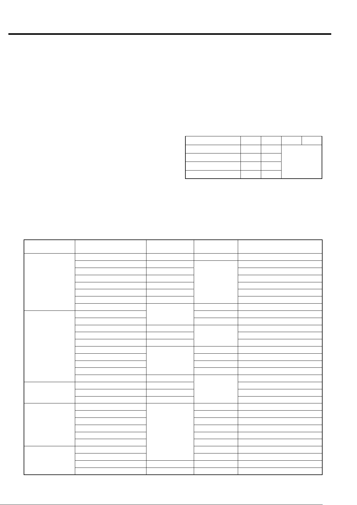
(1) How to Display the Operation Status
P: Dischargepressure(psi)
PressSWITCHDISPLAY.
Flasheswhenoperationtimeisadded.
Operationtime(×10)
表示切替
Proceedsby1each
Returnsby1each
Returnstodischarge
1
timepressed.
2
timepressed.
リセット
pressure.
b: Interstagepressure(psi)
C:Compressordischarge
temperature(℉)
(122℉)
L: Loadrate(%)
U: Loadcount(×10,000times)
H: Notused(displayonly)
d:Notused(displayonly)
Toshutdownhistorydisplay
IMPORTANT
1. When other than P0.00 is displayed, automatically
returns to P0.00 discharge pressure display in 3 minutes.
2. Load rate is a reference value determined by computation.
When the power is turned on, discharge pressure is displayed
on the screen of the digital monitor. Use the following proce-
dure to switch the digital monitor to other display.
Press the
①
SWITCH DISPLAY
button. Operation time is
then displayed on the screen.
Press the
②
SWITCH DISPLAY
button. Interstage pressure
is then displayed on the screen together with “b.”
③ Press the SWITCH DISPLAY button. Compressor discharge
temperature is then displayed on the screen together with
“C.”
Press the
④
SWITCH DISPLAY
button. Load rate is then dis-
played on the screen together with “L.”
Press the
⑤
SWITCH DISPLAY
button. Load count is then
displayed on the screen in units of 10,000 times together
with “U.”
Each time the SWITCH DISPLAY button is subsequently
pressed, it continues on to (2) Display of shutdown history
and (3) Monitor display of various settings. To return one
2
item at a time, press
. To return to discharge pres-
sure, press RESET.
● If the alarm or shutdown light is flashing, the shutdown code
is displayed along with “E0” (
page 33, 34).
“E0” indicates the contents of the latest shutdown.
● If the alarm or shutdown light is flashing, it indicates that
the alarm or shutdown has not been reset. Check E0.XX and
reset.
23
3. OPERATING THE DSP [How to Use the Digital Monitor]
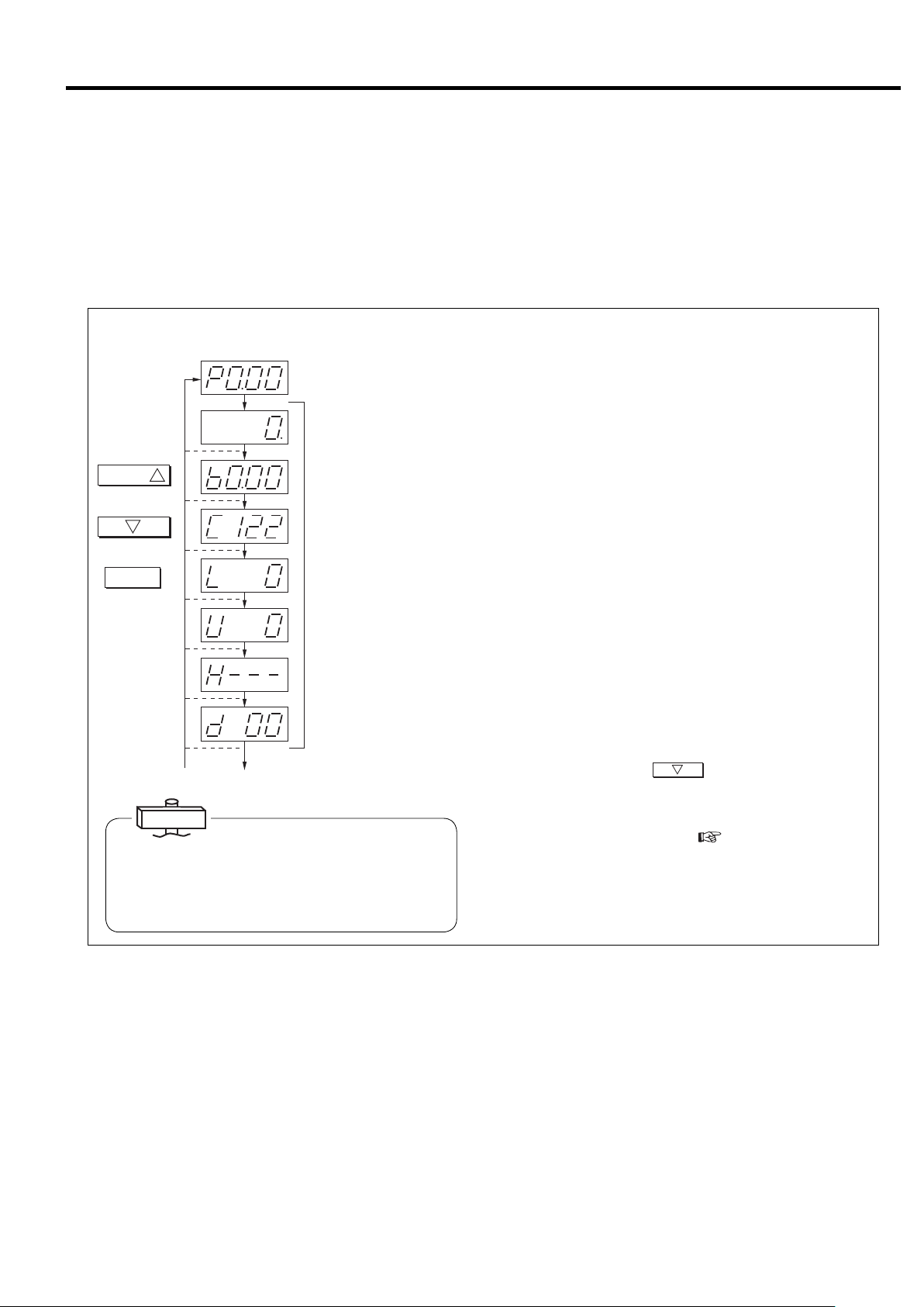
(2) How to Display Shutdown History
Use the following procedure to display shutdown history on the
Dischargepressuredisplay
表示切替
Proceedsby1each
Returnsby1each
Returnstodischarge
1
timepressed.
2
timepressed.
リセット
pressure.
SWITCHDISPLAY
1
Press8times.
[Localshutdown]
[1priorshutdown]
XX : Shutdowncode
[Oldestshutdown]
Historyconsistsof6items.
Notused(displayonly)
screen.
①
② Press the SWITCH DISPLAY button. “E1.” is then dis-
③ Press the RESET Button. The screen then returns to the
Press the
SWITCH DISPLAY
displayed together with the shutdown code (
button 8 times. “E0.” is the
page 33,
34). “0” indicates the latest shutdown. (Automatically chang-
es to “E.0” when shutdown or alarm occurs.)
played along with the shutdown code. “1” indicates shut-
down that occurred previously. Six items of data from 0 – 5
are recorded. “E5” indicates the oldest shutdown.
usual digital monitor display.
IMPORTANT
Notused(displayonly)
If the shutdown code “XX ”is “ ” it means there is no
shutdown history. Also, when anything other than shutdown history is displayed without resetting shutdown,
Todisplayofvarioussettings
it returns to the latest shutdown history in 3 minutes.
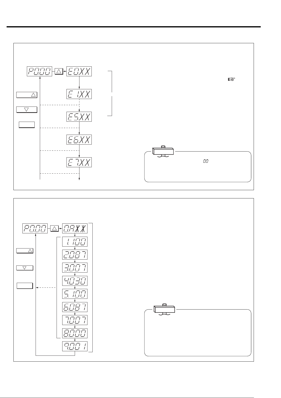
(3) How to Display Various Settings (Perform operation only when confirmation is
necessary.)
Dischargepressuredisplay
表示切替
1
Proceedsby1
eachtimepressed.
2
Returnsby1each
timepressed.
リセット
Returnsto
dischargepressure.
SWITCHDISPLAY
1
Press16times.
No.0 : Controlstatus
A : Capacitycontroltype
No.1 : Startpressure1
100 : 100psi
No.2 : Recoverpressure1
087 : 87psi
No.3 : Pressuredifferential1
007 : 7psi
No.4 : ECOMODE
[Energyconservationmode]
Decisiontime
No.5 : Startpressure2
100 : 100psi
Use the following procedure to display capacity control type
and pressure setting values for confirmation.
Press the
①
SWITCH DISPLAY
button 16 times. “0.A**” is
then displayed on the screen. ** changes with specifica-
tions. “A” may be “L” or “U” depending on capacity control
specifications.
② Consists of items 0 - 9. Pressure setting status and optional
pressure setting 2 can be confirmed each time the SWITCH
DISPLAY button is pressed.
③ Press the RESET Button. The screen then returns to the
usual discharge pressure display.
24
No.6 : Recoverpressure2
087 : 87psi
No.7 : Pressuredifferential2
007 : 7psi
No.8 : Instantaneouspower
interruption(IPI)setting
Invalid
000
:
No.9 : Compressoraddress
001 : No.1
IMPORTANT
Symbol displayed at No. 0 and corresponding capacity
control type
A: AUTO function setting
L: Fixed speed type setting
(INTE …Load/unload operation)
U: V type AUTO function off setting
For details on the various types, see pages 20 and 62 - 63.
3. OPERATING THE DSP [How to Use the Digital Monitor]
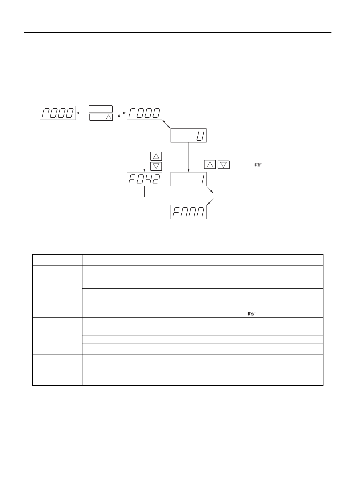
3.4.2 How to Set Control Functions
■ Various settings (instantaneous power interruption (IPI), remote operation, capacity control
setting, pressure setting, etc.)
Switches display from monitor mode to setting mode (F mode).
リセット
表示切替
Pressandhold
simultaneouslyforat
least3seconds.
Performsame
operationtoreturn.
1
Displays000
ChangeseachtimeFUNCTIONispressed.
th
itemofFmode.
Displayssettingcontents.
F000:(0:Setssingleunitoperation.)
Fordetails,seetheFmodetable.
1
2
Forward
Back
Toaltersettings,changethevalueswiththe
2
1
buttons.(page26)
F000:(1:Setsmultipleunitcontrol.)
PressENTERtoenterthesettings.
Back
Settings can be altered or entered into the memory from the digital monitor without opening the start panel.
Function
Multiple unit control setting
Instantaneous power interruption (IPI) restart setting
7 segment
display
Item Range
F000 Control setting 0 〜 110
F002
Instantaneous power interruption (IPI) setting
0〜1 1 00:ON、1:OFF
Instantaneous power inter-
F003
ruption (IPI) detection period
1〜511
setting"
Remote control switch
method
Remote operation shutdown recovery
0〜310
0〜1 1 00:Disable, 1:Enable
Remote operation setting
F005
F006 Remote operation method 0〜1 1 00:Pulse input, 1:Level input
F007
AUTO setting (*2) F011 AUTO operation enable 0〜1 1 00:Enable, 1:Disable
Capacity control F018 Control pressure selection 0〜210
Function setting
(optional)
F021 Pressure control mode 0〜210
Note:
※ Setting can be altered at any time other than this.
*1:When set to 1,” history is cleared. After clearing, the value is automatically reset to “0.”
*2:Only the V type is equipped with AUTO function. The AUTO function is available as an option for the Fixed speed type.
*3:Refer to the below chart about the Pressure setting.
Don’t change the setting of digital monitor besides the above parameter F (7 segment display: F
Precision/
unit
Initial value
***).
0: Single operation, 1: Multiple unit
control (communication supported)
When IPI is available, Instantaneous
power interruption is detected between
20ms and the setting detection period,
then the compressor restarts.
(
page 25)
0:Panel setting, 1:Local fi xed,
2:Remote fi xed,
3: Remote switch signal
0:Setting 1, 1:Setting 2,
2:External input
0:Built-in sensor, 1:External contact,
2:External input
25
3. OPERATING THE DSP [How to Use the Digital Monitor]
Function
Pressure
setting 1
※
(*3)
psi)
V type
】
125
【
MPa (110
】
0.86
【
0.75
Standard
type
V type
1.0 MPa (145 psi)
Standard
type
Shutdown history clear
Pressure
setting 2
※
(*3)
Pressure
setting 1
※
(*3)
Pressure
setting 2
※
(*3)
Pressure
setting 1
※
(*3)
Pressure
setting 2
※
(*3)
Pressure
setting 1
※
(*3)
Pressure
setting 2
※
(*3)
7 segment
display
F022
F023
F024
F025 (*2)
F031
F032
F033
F034 (*2)
F023
F024
F032
F033
F026
F027
F028
F029
F035
F036
F037
F038
F027
F028
F036
F037
F041 (*1)
Item Range
Control pressure setting 1
(control pressure)
Start pressure 1
(cut out pressure)
Recovery pressure 1
(cut in pressure)
P type recovery pressure 1
(restart pressure)
Control pressure setting 2
(control pressure)
Start pressure 2
(cut out pressure)
Recovery pressure 2
(cut in pressure)
P type recovery pressure 2
(restart pressure)
Start pressure 1
(cut out pressure)
Recovery pressure 1
(cut in pressure)
Start pressure 2
(cut out pressure)
Recovery pressure 2
(cut in pressure)
History Clear 0〜1 1 0 0 : Enter, 1 : History clear
0.5〜0.75 【0.86
(73〜110 【125】)
0.5〜0.77 【0.88
(73〜112 【128】)
0.5〜0.73 【0.84
(73〜106 【122】)
0.5〜0.73 【0.84
(73〜106 【122】)
0.5〜0.75 【0.86
(73〜110 【125】)
0.5〜0.77 【0.88
(73〜112 【128】)
0.5〜0.73 【0.84
(73〜106 【122】)
0.5〜0.73 【0.84
(73〜106 【122】)
0.5〜0.75 【0.86
(73〜110 【125】)
0.5〜0.65 【0.76
(73〜94 【110】)
0.5〜0.75 【0.86
(73〜110 【125】)
0.5〜0.65 【0.76
(73〜94 【110】)
0.5〜1.0
(73〜145)
0.5〜1.02
(73〜148)
0.5〜0.98
(73〜142)
0.5〜0.98
(73〜142)
0.5〜1.0
(73〜145)
0.5〜1.02
(73〜148)
0.5〜0.98
(73〜142)
0.5〜0.98
(73〜142)
0.5〜1.0
(73〜145)
0.5〜0.9
(73〜131)
0.5〜1.0
(73〜145)
0.5〜0.9
(73〜131)
Precision/
】
】
】
】
】
】
】
】
】
】
】
】
unit
0.01MPa
(1.5psi)
0.01MPa
(1.5psi)
0.01MPa
(1.5psi)
0.01MPa
(1.5psi)
0.01MPa
(1.5psi)
0.01MPa
(1.5psi)
0.01MPa
(1.5psi)
0.01MPa
(1.5psi)
0.01MPa
(1.5psi)
0.01MPa
(1.5psi)
0.01MPa
(1.5psi)
0.01MPa
(1.5psi)
0.01MPa
(1.5psi)
0.01MPa
(1.5psi)
0.01MP
(1.5psi)
0.01MPa
(1.5psi)
0.01MPa
(1.5psi)
0.01MPa
(1.5psi)
0.01MPa
(1.5psi)
0.01MPa
(1.5psi)
0.01MPa
(1.5psi)
0.01MPa
(1.5psi)
0.01MPa
(1.5psi)
0.01MPa
(1.5psi)
Initial value
0.75 【0.86
(110 【125】)
0.77 【0.88
(112 【128】)
0.72 【0.83
(104 【120】)
0.72 【0.83
(104 【120】)
0.75 【0.86
(110 【125】)
0.77 【0.88
(112 【128】)
0.72 【0.83
(104 【120】)
0.72 【0.83
(104 【120】)
0.75 【0.86
(110 【125】)
0.65 【0.76
0.75 【0.86
(110 【125】)
0.65 【0.76
a
(94 【110】)
(94 【110】)
1.0
(145)
1.02
(148)
0.97
(141)
0.97
(141)
1.0
(145)
1.02
(148)
0.97
(141)
0.97
(141)
1.0
(145)
0.9
(131)
1.0
(145)
0.9
(131)
】
】
】
】
Setting can be altered at any time.
※
】
】
】
】
】
】
Setting can be altered at any time.
※
】
】
Setting can be altered at any time.
※
Setting can be altered at any time.
※
●Pressure setting condition
Type Setting condition (Example of Pressure setting 1)
Standard type
V type
①Start pressure (F023) cannot be set below the value of Recovery pressure (F024) (F025) + 3 psi.
① Start pressure (F023) cannot be set below the value of Control pressure (F022) + 3 psi.
② Recovery pressure cannot be set above the value of Control pressure (F022).
Note 1. The higher value, in which value of Recovery pressure (F024) or (F025), becomes the standard type condition ①.
2. The setting condition is same in case of Pressure setting 2 (F031〜F034).
IMPORTANT
1. Pressure setting
V type: Set pressure differential of start pressure and recovery pressure to a minimum of 7 psi when using a standard receiv-
er. Set Pressure differential of start pressure and control pressure to a minimum of 3 psi.
Fixed speed type: Set pressure differential of start pressure and recovery pressure to a minimum of 15 psi.
2. Function for switching to pressure setting 2 by external pressure alteration input is optional.
26
3. OPERATING THE DSP [How to Use the Digital Monitor]
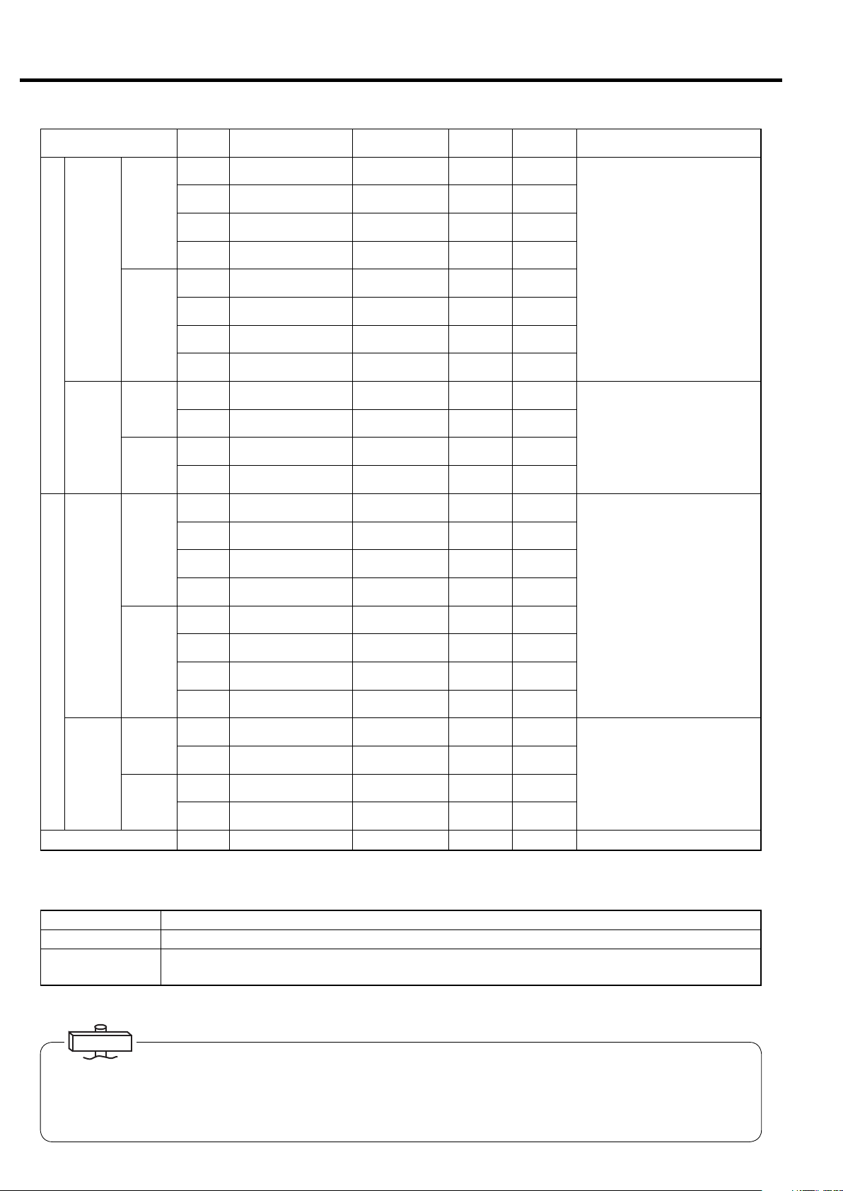
3.4.3 Alteration of Pressure Setting Values
Pressure
setting1
Pressbutton.
機能
Pressbutton.
記憶
1
Alter
values.
2
Use the following procedure to alter the pressure setting
values for the capacity control system.
① Switch from monitor mode to setting mode (F mode).
② Set PRESSURE SETTING 1 of F mode.
(For detailed contents of setting specifications, see
page 26.)
If using pressure setting 2, you must also set pres-
sure setting 2.
For operation method, be sure to refer to the various
settings, and after entering the setting values with the
STORE button, return to the monitor mode.
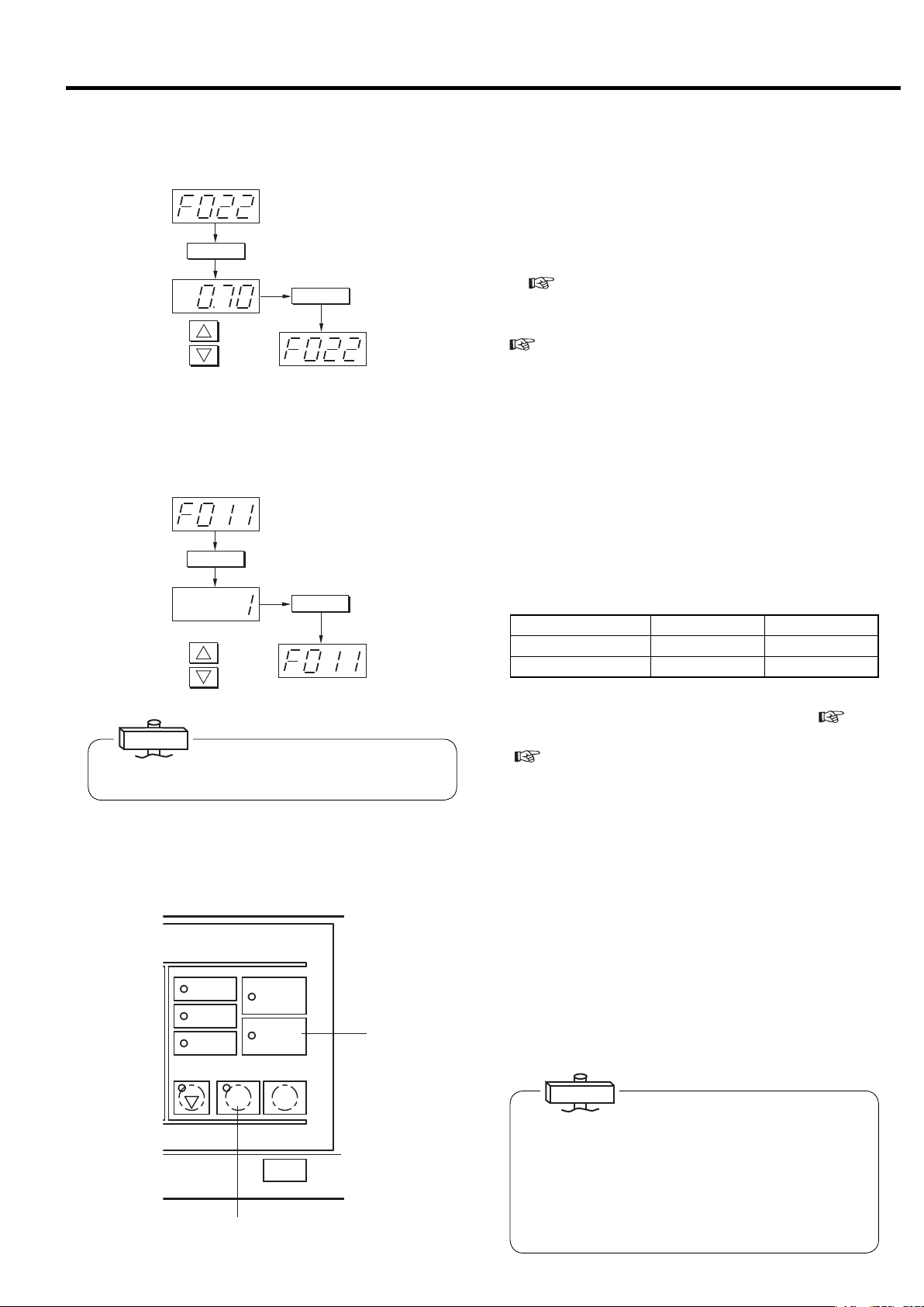
3.4.4 Capacity Control Mode Setting and
Confirmation
AUTOsetting
機能
Pressbutton.
Pressbutton.
記憶
SettoAUTOOFF.
(Initialvalue0)
1
Alter
values.
2
IMPORTANT
The AUTO function is available for the Fixed speed type
as an option.
3.4.5 Restart for Instantaneous Power
Interruption
運転状況
RUNNINGMODE
遠方
REMOTE
負荷
LOAD
故障
SHUTDOWN
2
電源
POWER
起動待ち
AUTOSTART
運転 停止
START
STOP
UNLOAD STOP
②③
③
You can switch the capacity control mode by the following method according to the application. The V type is a
automatic stop type, but can also be changed to control
mode that does not stop automatically (AUTO OFF).
Capacity control mode setting can be changed by switching the digital monitor from monitor mode to setting
mode (F mode) while the compressor is not running and
setting to “0: Enable” or “1: Disable” by altering the
AUTO setting (F011) of F mode.
Capacity control mode AUTO ON AUTO OFF
F011 0 : Enable 1 : Disable
Digital monitor display
0.AXX0.UXX
After altering, confirm the capacity control mode by display of various settings on the digital monitor (
page
23).
For capacity control operation and details, see pages
(
29 and 62 - 63. Pressure for control can also be
switched by F018 (pressure setting 1 / pressure
setting 2).
The DSP has restart function for instantaneous power
interruption (IPI). When the DSP detects IPI, blinking
the AUTO START Light, the DSP restarts automatically.
① This function is abailable for IPI between 20ms and 5
seconds.
② The DSP stops automatically after detecting IPI and
the OPERATION Light is turned off.
③ After recovering the voltage, the AUTO START Light
blinks and the OPERATION Light turns on.
④ The DSP restarts automatically.
IMPORTANT
(1) Instantaneous power interruption (IPI) means that the
power voltage drops to zero (0) instantaneously.
(2) For the IPI time of less than 20 ms, the DSP air com-
pressor will continue to run.
(3) For the IPI time of more than the setting, the DSP judg-
es it as a power failure; the DSP stops but does not
restart automatically. Press the START button to restart
the DSP air compressor.
27
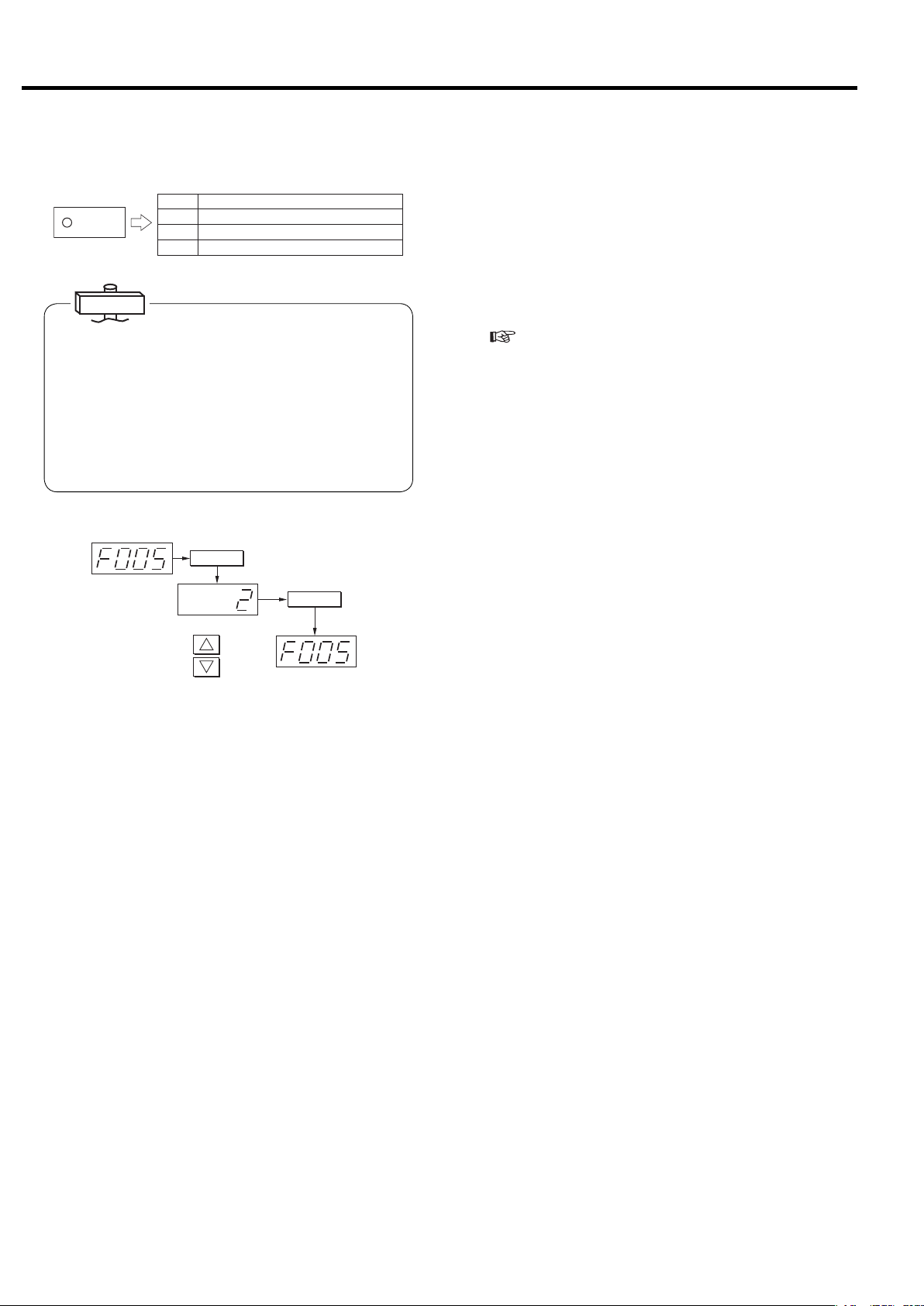
3. OPERATING THE DSP [How to Use the Digital Monitor]
3.4.6 Remote Operation Setting
(1) Remote setting by instrument panel
On
(2) Remote setting fixed
遠 方
REMOTE
IMPORTANT
● In the case of multiple unit control specifications, when
multiple unit control is set, it automatically changes to
the remote setting. The REMOTE light flashes at this
time.
● Remote operation method alteration in the setting
mode can only be entered when the compressor is not
operating.
● The compressor STOP button can also be used to
stop operation when operating in the remote mode.
Remote
operation
switch
method
On
(3) Remote setting by external operation button
Flashing
Local setting
Off
機能
Pressbutton.
(Initialvalue1)
1
Alter
values.
2
Pressbutton.
記憶
Settoremotefixed.
Operation mode is basically switched by panel operation.
The remote operation mode can also be set by methods
(2) and (3).
① Turn off the main power supply.
② Remove the front cover and remove the start panel
cover.
③ Connect the wiring of the remote control panel and
the compressor control panel.
(
See the wiring diagrams on pages 51 - 56.)
④ Mount the start panel cover and the front cover.
⑤ Turn on the main power supply.
[1] To “set the operation buttons of the instrument
panel to remote operation mode”
① Press the REMOTE button.
② The REMOTE light lights to indicate that operation of
the instrument panel buttons is set to the remote
operation mode.
③ To return to local operation mode, press the
REMOTE button again. The REMOTE light then
goes off to indicate that operation has been switched
to the local operation mode.
[2] To “fix remote operation to remote operation
mode”
① Switch from the monitor mode to the setting mode (F
mode).
② Change the remote operation switch method for
remote operation setting (F005) from “0: Panel set-
ting” to “2: Remote fixed.”
③ The REMOTE light lights to indicate that the remote
operation mode has been set.
[3] To “set to remote operation by operation button
provided externally”
(Consult with your dealer or the Hitachi Service
Station.)
① Wire the external remote setting buttons.
② Switch from the monitor mode to the setting mode (F
mode).
③ Change the remote operation switch method for
remote operation setting (F005) from “0: Panel set-
ting” to “3: Remote switch signal.”
28
④ Set the external remote setting button to “ON.”
⑤ The REMOTE light flashes to indicate that the opera-
tion mode has been switched to remote operation by
external buttons.
 Loading...