

Hitachi DSP-90A6N, DSP-90W6N, DSP-110A6N, DSP-110W6N, DSP-90VA6N Instruction Manual
...
INSTRUCTION MANUAL
HITACHI Oil-Free Rotary Screw Air Compressor
Air-Cooled
DSP-90A6N DSP-110A6N
DSP-90VA6N DSP-110VA6N
Water-Cooled
DSP-90W6N DSP-110W6N
DSP-90VW6N DSP-110VW6N
Prior to operation of this air compressor,
ensure that all operators read and
understand this INSTRUCTION
MANUAL completely, thereby operating
it safely and properly.
Place the INSTRUCTION MANUAL
near the air compressor to make it
available at any time, and refer to it as
the need arises.
● This INSTRUCTION MANUAL explains in detail
the important items that require attention;
observed as the following:
Always observe Instructions of WARNING,
●
CAUTION
considerable risks to safety.
WARNING
CAUTION
Air-Cooled
Water-Cooled
IMPORTANT
and IMPORTANT, as they indicate
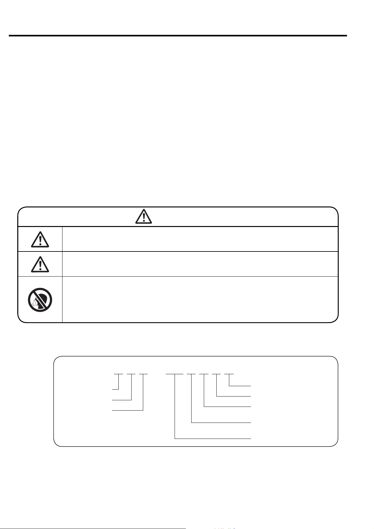
GRAPHIC DESCRIPTIONS:
:Indicates warnings. If handled
improperly, death or severe injury
could result.
:Indicates cautions. If handled
improperly, injury and/or physical
damage could result.
:Indicates air-cooled type.
:Indicates water-cooled type.
:Indicates variable speed type.
:Indicates information that needs
attention, other than WARNING and
CAUTION.
:Indicates a reference page.
How to Use This Instruction Manual
● This Instruction Manual covers the standard models of the Hitachi DSP air compressor.
● This Instruction Manual intended to assist daily operators and maintenance personnel
in the installation, operation, control and service of the air compressor.
● Prior to operation of this air compressor, ensure that all operators read and understand
this INSTRUCTION MANUAL completely, thereby operating it safely and properly.
Place the INSTRUTION MANUAL near the air compressor to make it available at any
time, and refer to it as the need arises.
● If there are any questions or comments, please contact the local Hitachi distributor/
master dealer or representative office.
● Fill your compressor’s model name, Serial Number, etc. in Section 13 of this
Instruction Manual. Such information may be helpful when ordering parts, periodic
maintenance, and overhaul.
■ Model Code
Dry or Oil-Free Rotary
Screw Air Compressor
WARNING
Never remove a protective device from the air compressor or
modify the air compressor.
It is imperative to install an earth leakage (ground) circuit breaker
on the power cable. This prevents a ground fault accident.
DSP air compressors are not designed, intended or approved for
breathing air applications. Hitachi does not approve specialized
equipment for breathing air applications and assumes no responsibility or liability for compressors used for breathing air services.
DSP-90VA6N
NEXTseries
Frequency (5: 50 Hz, 6: 60 Hz)
Packaged
Cooling Method (A: air-cooled ,
W: water-cooled)
V: V type
without V: fixed-speed type
Nominal Output (kW)
● For improvement of the product, contents in this manual are subject to change without notice. Please be forewarned.

Contents
1. SAFETY PRECAUTIONS ………………………………………………………………………………………… 2
2.1 Appearance
2.
GENERAL DESCRIPTION
2.2 Components …………………………………………………………………… 8
2.3 Daily Operating Components ……………………………………………… 10
3.
OPERATING PROCEDURE
3.2 Start/Stop Operation ………………………………………………………… 14
3.3 How to Use the Liquid Crystal Display (LCD)……………………………… 15
3.4 How to Use the Digital Monitor …………………………………………… 25
3.5 Daily Operation of Air Compressor ………………………………………… 32
3.6 Daily Operation of Oil Mist Remover ……………………………………… 34
3.7 Adjusting Procedure…………………………………………………………… 35
3.1 Instrument Panel ……………………………………………………………… 12
4. TROUBLESHOOTING 4.1 Protective Device……………………………………………………………… 36
4.2 Troubleshooting of Air Compressor………………………………………… 38
4.3 Troubleshooting of Oil Mist Remover……………………………………… 39
5.
INSTALLING AND PIPING
5.1 Unpacking the Air Compressor ……………………………………………… 40
THE DSP 5.2 Conveying the Air Compressor ……………………………………………… 40
5.3 Installing the Air Compressor ……………………………………………… 41
5.4 Piping the Air Compressor …………………………………………………… 42
5.5 Ventilation of Air Compressor Room ……………………………………… 45
……………………………………………………………………… 6
6. STARTUP OPERATION 6.1 Startup Operation of the Air Compressor ………………………………… 47
6.2 Initial Setting of OMR Regulator …………………………………………… 50
7. WIRING 7.1 Power Supply Equipment …………………………………………………… 51
7.2 MIV and WIVM Wiring ………………………………………………………… 51
7.3 Connecting the Power Cable ………………………………………………… 52
7.4 Wiring Diagram………………………………………………………………… 54
7.5 Control Panel /LCD monitor Specifications ……………………………… 54
8.
STANDARD COMPONENTS
AND SUBSYSTEMS
8.3 Cooling Water ………………………………………………………………… 66
8.4 Capacity Control System……………………………………………………… 67
8.5 Oil Mist Remover System …………………………………………………… 73
8.2 Air/Oil/Water Flow……………………………………………………………… 61
8.1 Standard Components………………………………………………………… 60
9. MAINTENANCE 9.1 Periodical maintenance of Air compressor………………………………… 74
9.2 Standard Maintenance Schedule …………………………………………… 75
9.3 Maintenance Schedule for Oil Mist Remover……………………………… 79
9.4 How to Service the Air Compressor………………………………………… 80
10. CAUTIONS FOR A LONG TERM OPERATION SUSPENSION…………………………………………… 94
11. PARTS LIST ………………………………………………………………………………………… 95
12. RELOCATION AND 12.1 Relocation…………………………………………………………………… 119
DISPOSAL 12.2 Disposal……………………………………………………………………… 11 9
13. WARRANTY AND 13.1 Warranty……………………………………………………………………… 120
AFTER-SALES SERVICE
13.2 After-Sales Service ………………………………………………………… 120
14. OPERATION RECORD LOGBOOK…………………………………………………………………………… 121
15. STANDARD SPECIFICATIONS………………………………………………………………………………… 122
1

1. SAFETY PRECAUTIONS
013B0816
012B1240012B1240
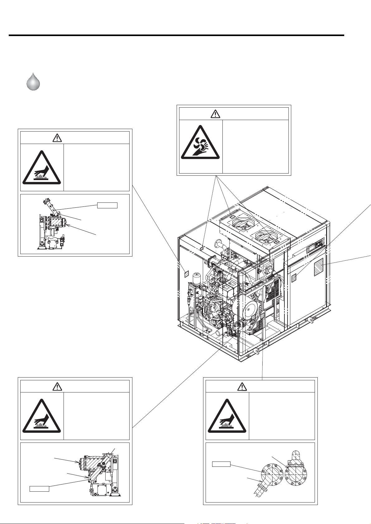
To ensure safe and proper operation of the air compressor, it is indispensable to carefully
read and understand the following warnings and instructions detailed below. These
warnings and instructions are attached to the air compressor as shown in the figure
below.
Air-Cooled
DSP- 90/110A6N
90/110VA6N
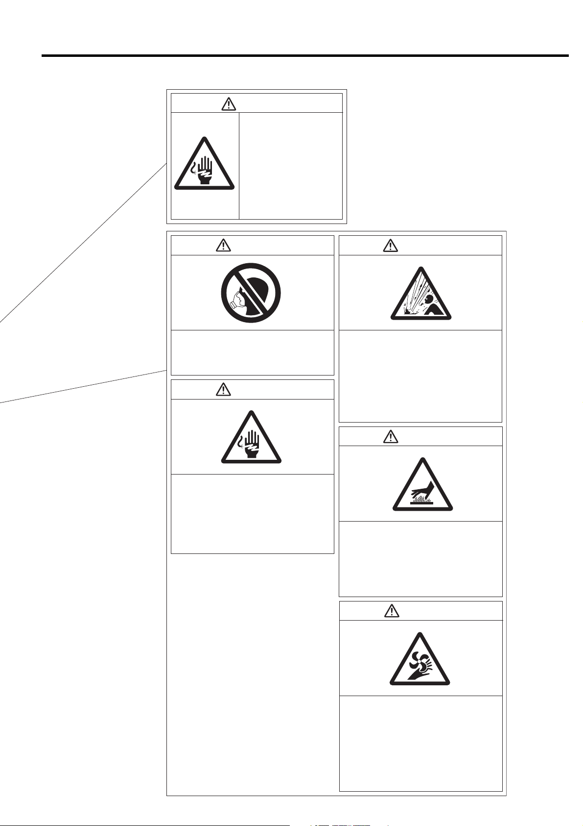
WARNING
Hot Surface!
●Do not directly touch any component
inside the air compressor enclosure
when the air compressor is operating
or immediately after it has stopped,
as the components are extremely hot
and can cause severe injury.
●Before servicing the air compressor,
stop it, disconnect the power, then
wait for the air compressor to cool
down.
Heated!!
WARNING
Rotating Parts!
●Keep hands and rods, etc. away from
the rotating parts (Cooling fans, etc.)
●Use caution at all times, when air com-
pressor is powered. The air compressor may be capable of restarting without hitting the START button.
●When the air compressor is operating,
do not remove or open the enclosure
panels and doors.
●
Before servicing the air compressor,
stop it, disconnect the power, especially when accessing any rotating parts.
Discharge Air pipe
Air End
WARNING
Hot Surface!
●Do not directly touch any component
inside the air compressor enclosure
when the air compressor is operating
or immediately after it has stopped,
as the components are extremely hot
and can cause severe injury.
●Before servicing the air compressor,
stop it, disconnect the power, then
wait for the air compressor to cool
down.
Air End
Discharge Air Pipe
Heated!!
2
Aftercooler
Heated!!
Intercooler
1. SAFETY PRECAUTIONS
WARNING
Electric Shock Hazard!
●Before servicing or wiring the
air compressor, disconnect
the power. This will prevent
anyone from turning on the
power and causing an electric shock that could lead to
severe injury or death.
●Do not allow any unlicensed
person to wire the air compressor. Always use a licensed
electrician.
●Ground the air compressor.
WARNING WARNING
Do Not Breathe Air!
Discharge air can contain Carbon Monoxide and
other contaminants. Breathing the air can cause
severe injury or death.
WARNING
Electric Shock Hazard!
●
Before servicing or wiring the air compressor,
disconnect the power. This will prevent anyone
from turning on the power and causing an electric
shock that could lead to severe injury or death.
●
Do not allow any unlicensed person to wire the air
compressor. Always use a licensed electrician.
●Ground the air compressor.
●
High pressure air can cause severe injury or death.
Be careful when air compressor is operating.
Pressurized air can blow out of air relief valves and
etc. at incredibly high velocities.
●When using compressed air to clean equipment,
use extreme caution and/or wear eye protection.
●Before servicing the air compressor, stop it,
disconnect the power, and relieve pressure before
removing filter, plug, fitting or cover.
WARNING
High Pressure Air!
Hot Surface!
●Do not directly touch the air end, discharge air
pipe,and coolers when the air compressor is
operating and immediately after it has stopped,
because these parts are heated then.
Before servicing the air compressor (especially
●
when accessing to the heated parts), stop it, disconnect the power, and wait until it is cooled down.
WARNING
●Keep hands and rods, etc. away from the rotating
Rotating Parts!
parts (Cooling fans, etc.)
●Use caution at all times, when air compressor is
powered. The air compressor may be capable of
restarting without hitting the START button.
●When the air compressor is operating, do not
remove or open the enclosure panels and doors.
●Before servicing the air compressor, stop it, dis-
connect the power, especially when accessing
any rotating parts.
3
1. SAFETY PRECAUTIONS
013B0816
012B1240012B1240
Water-Cooled
DSP- 90/110W6N
90/110VW6N
WARNING
Hot Surface!
●Do not directly touch any component
inside the air compressor enclosure
when the air compressor is operating
or immediately after it has stopped,
as the components are extremely hot
and can cause severe injury.
●Before servicing the air compressor,
stop it, disconnect the power, then
wait for the air compressor to cool
down.
Heated!!
Discharge Air pipe
Air End
WARNING
Rotating Parts!
●Keep hands and rods, etc. away from
the rotating parts (Cooling fans, etc.)
●Use caution at all times, when air com-
pressor is powered. The air compressor may be capable of restarting without hitting the START button.
●When the air compressor is operating,
do not remove or open the enclosure
panels and doors.
●
Before servicing the air compressor,
stop it, disconnect the power, especially when accessing any rotating parts.
Air End
Discharge Air Pipe
Heated!!
4
WARNING
Hot Surface!
●Do not directly touch any component
inside the air compressor enclosure
when the air compressor is operating
or immediately after it has stopped,
as the components are extremely hot
and can cause severe injury.
●Before servicing the air compressor,
stop it, disconnect the power, then
wait for the air compressor to cool
down.
Heated!!
Intercooler
WARNING
Hot Surface!
●Do not directly touch any component
inside the air compressor enclosure
when the air compressor is operating
or immediately after it has stopped,
as the components are extremely hot
and can cause severe injury.
●Before servicing the air compressor,
stop it, disconnect the power, then
wait for the air compressor to cool
down.
Aftercooler

1. SAFETY PRECAUTIONS
WARNING
Electric Shock Hazard!
●Before servicing or wiring the
air compressor, disconnect
the power. This will prevent
anyone from turning on the
power and causing an electric shock that could lead to
severe injury or death.
●Do not allow any unlicensed
person to wire the air compressor. Always use a licensed
electrician.
●Ground the air compressor.
WARNING WARNING
Do Not Breathe Air!
Discharge air can contain Carbon Monoxide and
other contaminants. Breathing the air can cause
severe injury or death.
WARNING
Electric Shock Hazard!
●
Before servicing or wiring the air compressor,
disconnect the power. This will prevent anyone
from turning on the power and causing an electric
shock that could lead to severe injury or death.
●
Do not allow any unlicensed person to wire the air
compressor. Always use a licensed electrician.
●Ground the air compressor.
●
High pressure air can cause severe injury or death.
Be careful when air compressor is operating.
Pressurized air can blow out of air relief valves and
etc. at incredibly high velocities.
●When using compressed air to clean equipment,
use extreme caution and/or wear eye protection.
●Before servicing the air compressor, stop it,
disconnect the power, and relieve pressure before
removing filter, plug, fitting or cover.
WARNING
High Pressure Air!
Hot Surface!
●Do not directly touch the air end, discharge air
pipe,and coolers when the air compressor is
operating and immediately after it has stopped,
because these parts are heated then.
Before servicing the air compressor (especially
●
when accessing to the heated parts), stop it, disconnect the power, and wait until it is cooled down.
WARNING
●Keep hands and rods, etc. away from the rotating
Rotating Parts!
parts (Cooling fans, etc.)
●Use caution at all times, when air compressor is
powered. The air compressor may be capable of
restarting without hitting the START button.
●When the air compressor is operating, do not
remove or open the enclosure panels and doors.
●Before servicing the air compressor, stop it, dis-
connect the power, especially when accessing
any rotating parts.
5
2. GENERAL DESCRIPTION
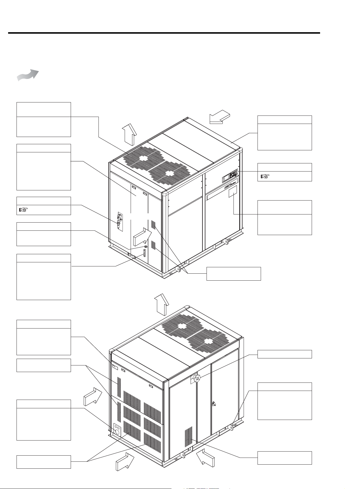
2.1 Appearance
This section illustrates and describes the major components of the DSP air compressor. Be familiar
with the name, location and function of each component before using the DSP air compressor.
Air-Cooled
DSP- 90/110A6N
90/110VA6N
[Front View]
Air Exhaust
(Air Compressor Package)
This panel discharges
the hot air generated
in the air compressor.
Left Door
Open the left door only
when servicing the
DSP air compressor.
Keep it closed when
operating the DSP air
compressor.
OMR
8.5 for the details
Oil Filling Port
Use the port to fill the
gear case with oil.
Air Exhaust
Air Intake
Air Intake
Enclosure
Enclosure panels
lower the sound level
of the air compressor
package.
Instrument Panel
3.1
Plate of Operating /
Servicing Instructions
Read carefully the
plate before operating
and servicing the DSP.
Oil Level Gauge
This indicates the
quantity of the oil in
the gear case. Check
the oil level before
starting the DSP and
when operating it.
[Rear View]
Compressor Name plate
Model designation,
manufacturing number
and specification are
printed.
Air Intake
(Air for inverter)
Air Intake
Power Supply Port
Check the specifications, power supply
and voltage before
connecting the power
supply.
Air Intake
(Inlet to the Air End)
Air Exhaust
Compressed Air Discharge
Sling Fitting
Use the sling fitting
when moving and
installing the DSP air
compressor.
Air Intake
(Air for coolers)
6
Air Intake
Air Intake
Air Intake
(Air Compressor Package)
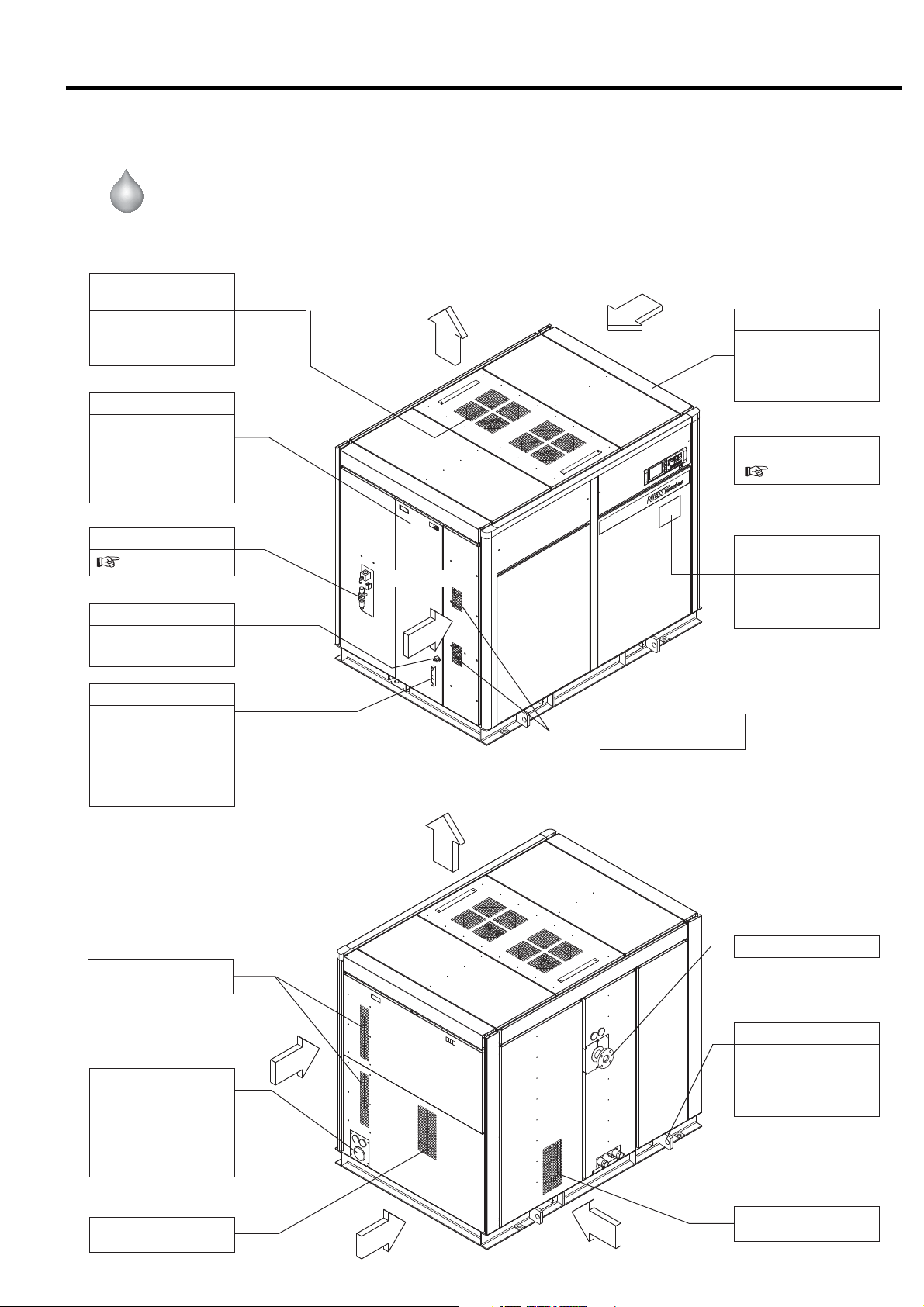
2. GENERAL DESCRIPTION [Appearance]
Water-Cooled
DSP- 90/110W6N
90/110VW6N
[Front View]
Air Exhaust
(Air Compressor Package)
This panel discharges
the hot air generated
in the air compressor.
Left Door
Open the left door
only when servicing
the DSP air compressor. Keep it closed
when operating the
DSP air compressor.
OMR
8.5 for the details
Oil Filling Port
Use the port to fill the
gear case with oil.
Air Exhaust
Air Intake
Air Intake
Enclosure
Enclosure panels
lower the sound level
of the air compressor
package.
Instrument Panel
3.1
Plate of Operating /
Servicing Instructions
Read carefully the
plate before operating
and servicing the DSP.
Oil Level Gauge
This indicates the
quantity of the oil in
the gear case. Check
the oil level before
starting the DSP and
when operating it.
[Rear View]
Air Intake
(Air for inverter)
Air Intake
Power Supply Port
Check the specifications, power supply
and voltage before
connecting the power
supply.
Air Intake
(Inlet to the Air End)
Air Exhaust
Compressed Air Discharge
Sling Fitting
Use the sling fitting
when moving and
installing the DSP air
compressor.
Air Intake
(Air for Package)
Air Intake
Air Intake
Air Intake
(Air Compressor Package)
7
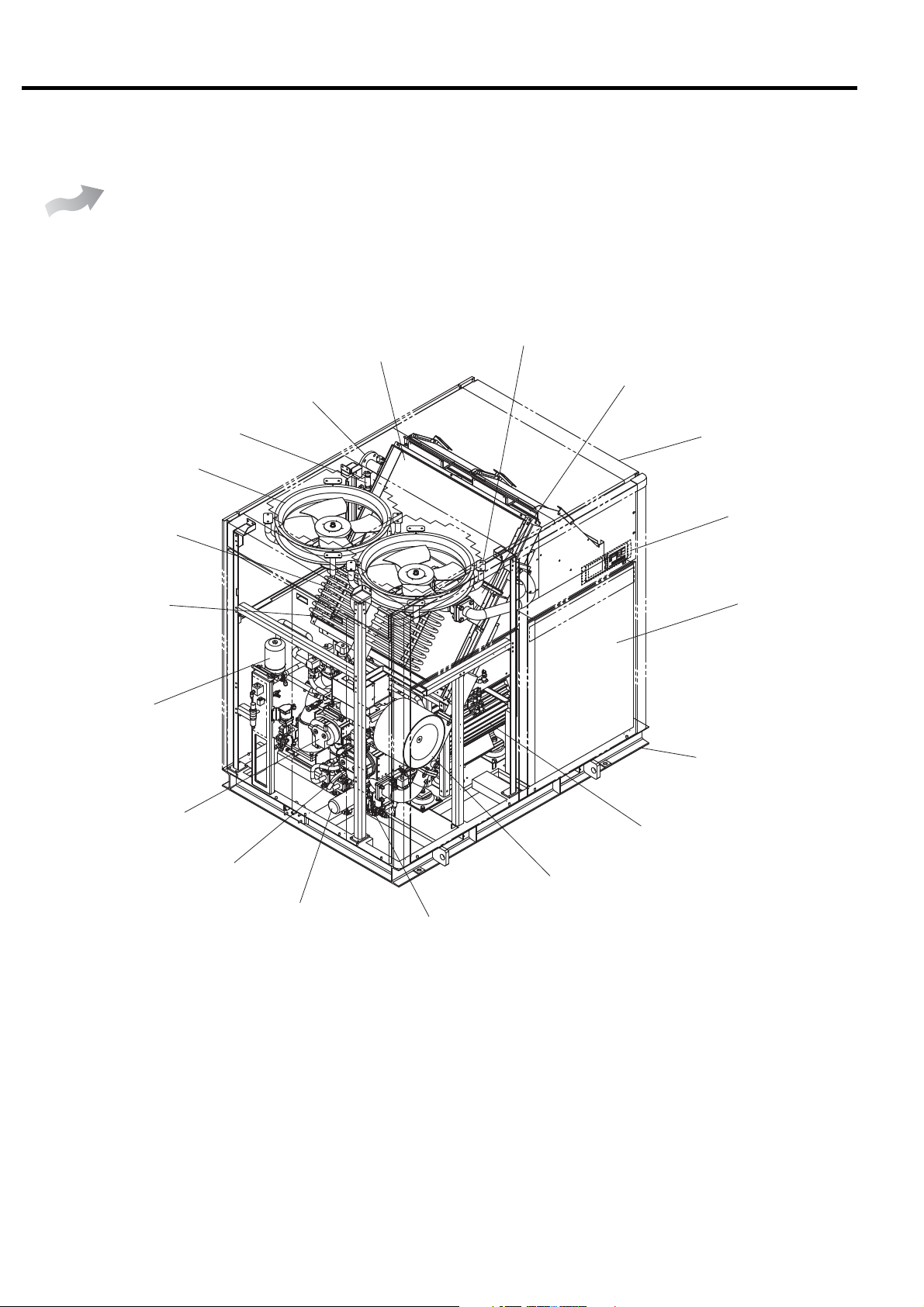
2. GENERAL DESCRIPTION [Components]
2.2 Components
Air-Cooled
Hi-precooler
DSP- 90/110A6N
90/110VA6N
Discharge pipe (Compressed
Air Discharge)
Air relief valve
Cooling fan
Oil cooler
Check valve
Aftercooler
Intercooler
Enclosure
Instrument panel
Control panel
Oil mist remover
2nd-stage air end
1st-stage air end
Common base
Main motor
Air intake filter
Oil filter
Oil level gauge
8
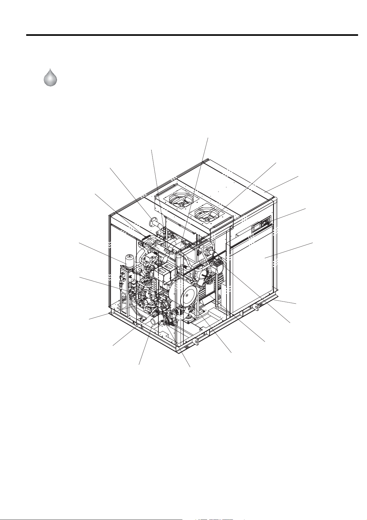
2. GENERAL DESCRIPTION [Components]
Water-Cooled
Oil mist remover
DSP- 90/110W6N
90/110VW6N
Discharge pipe
(Compressed air discharge)
Intercooler
Aftercooler
Air relief valve
Cooling fan
Enclosure
Instrument panel
Control panel
2nd-stage air end
Oil cooler
1st-stage air end
Oil filter
Common base
Check valve
Main motor
Air intake filter
Oil level gauge
9
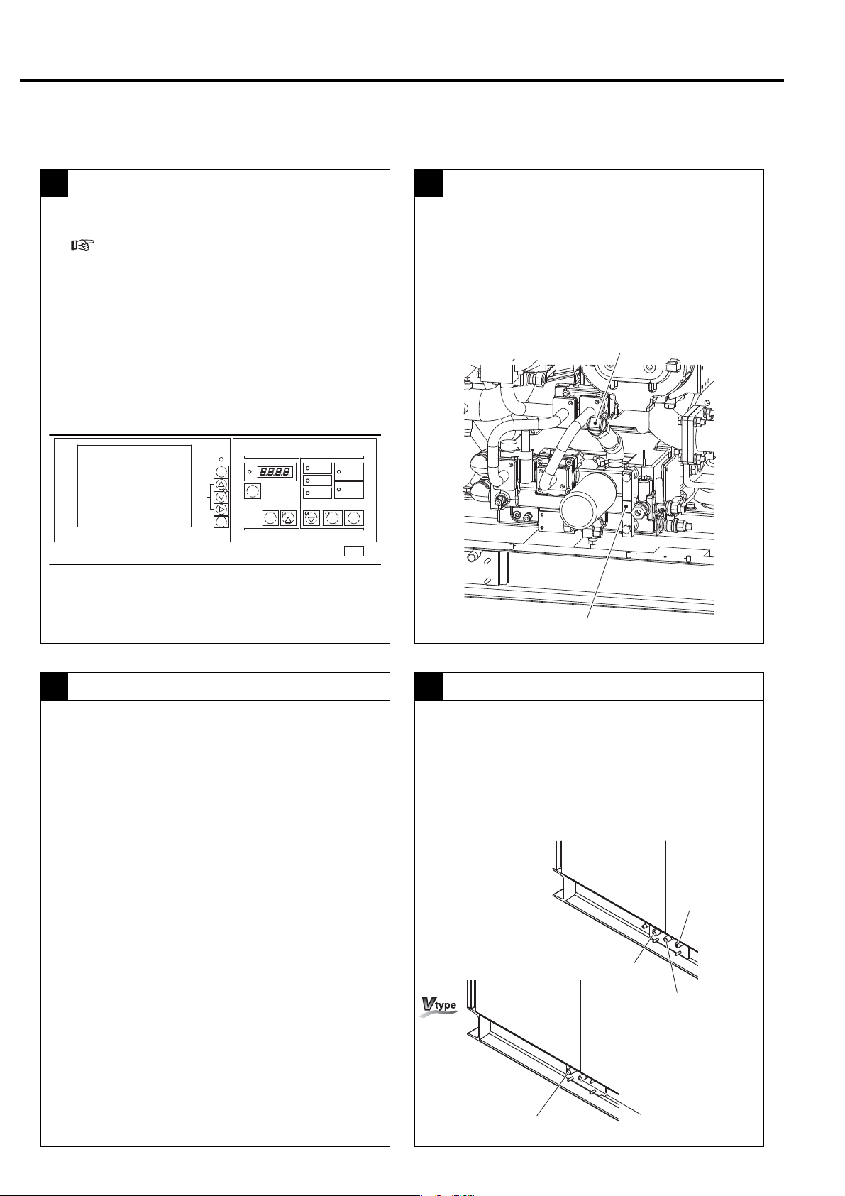
2. GENERAL DESCRIPTION [Daily Operating Components]
2.3 Daily Operating Components
Controls on the Instrument Panel
1 2
● Indicates the operation control section.
(
3.1)
● Power ON → The Power light ON.
● Start: Press the START button. → Start light ON.
● Stop: Press the UNLOAD STOP button. →
The compressor unloads for 5 minutes and then
stops. → Start light OFF.
● Power OFF: → Power light OFF.
MONITOR
AUTO
MONITOR
MENU
+/−
UP/
DOWN
SET
RUNNINGCONTROL
ALARM
FUNC
RESET
REMOTE
STR
[×10h]
SELECT/WIDE
1
RUNNINGMODE
REMOTE
LOAD
SHUTDOWN
2
START
POWER
AUTOSTART
STOP
UNLOAD STOP
Oil Level Gauge
● Verify that the oil stays between the upper and
lower red lines of the oil level gauge during the
operation.
Oil level might be higher than upper line during air
compressor
and pipings.
stopping due to oil returning from the cooler
Oil Filling Port
Lubricating Oil
3 4
Oil: Use genuine Hitachi GL-68 DSP Compressor Oil.
Replace the oil every 8,000h operating hour or every
2-year, whichever comes earlier.
Oil Level Gauge
Aftercooler and Intercooler - Condensate Drain Valve
● Verify that air containing condensate is discharged
intermittently from the intercooler and aftercooler
drain ports.
The higher temperature and humidity, the more condensate
is produced. Condensate may not be produced on the
intercooler side during winter.
[Fixed speed type]
Control pipe filter
drain port
Intercooler
drain port
Aftercooler
drain port
10
Intercooler
drain port
Aftercooler
drain port

Water-Cooled
2. GENERAL DESCRIPTION [Daily Operating Components]
Cooling Water
5
① Stop the cooling water flow when the DSP has
stopped running.
② Open the water drain peacock and the water drain
valve at the water drain port to remove the cooling
water from the system.
③ Take care to completely drain the cooling water
during the winter season to prevent freezing in the
cooling water pipes (
Water drain peacock
8.3)
Control Line Filter
6
[Fixed speed type]
● Check the sight glass on the control line filter to
make sure that the condensate discharged
properly.
Control line filter
Sight Glass
Water drain port
Stopping operation
7
● Normally use the UNLOAD STOP button to stop
the air compressor. The air compressor then
unloads for 5 minutes and stops running.
(In the case of an emergency, press the
EMERGENCY STOP button to stop operation.)
RUNNINGCONTROL
ALARM
FUNC
RESET
REMOTE
STR
MONITOR
AUTO
MONITOR
MENU
+/−
UP/
DOWN
SET
IMPORTANT
Keeping the second-stage air end as dry as possible
is essential for preventing it from rusting due to a long
term operation suspension. When stopping the DSP,
therefore, execute an unloading operation and thereby
remove the moisture from the second-stage air end.
[×10h]
SELECT/WIDE
1
RUNNINGMODE
REMOTE
LOAD
SHUTDOWN
2
START
POWER
AUTOSTART
STOP
UNLOAD STOP
11
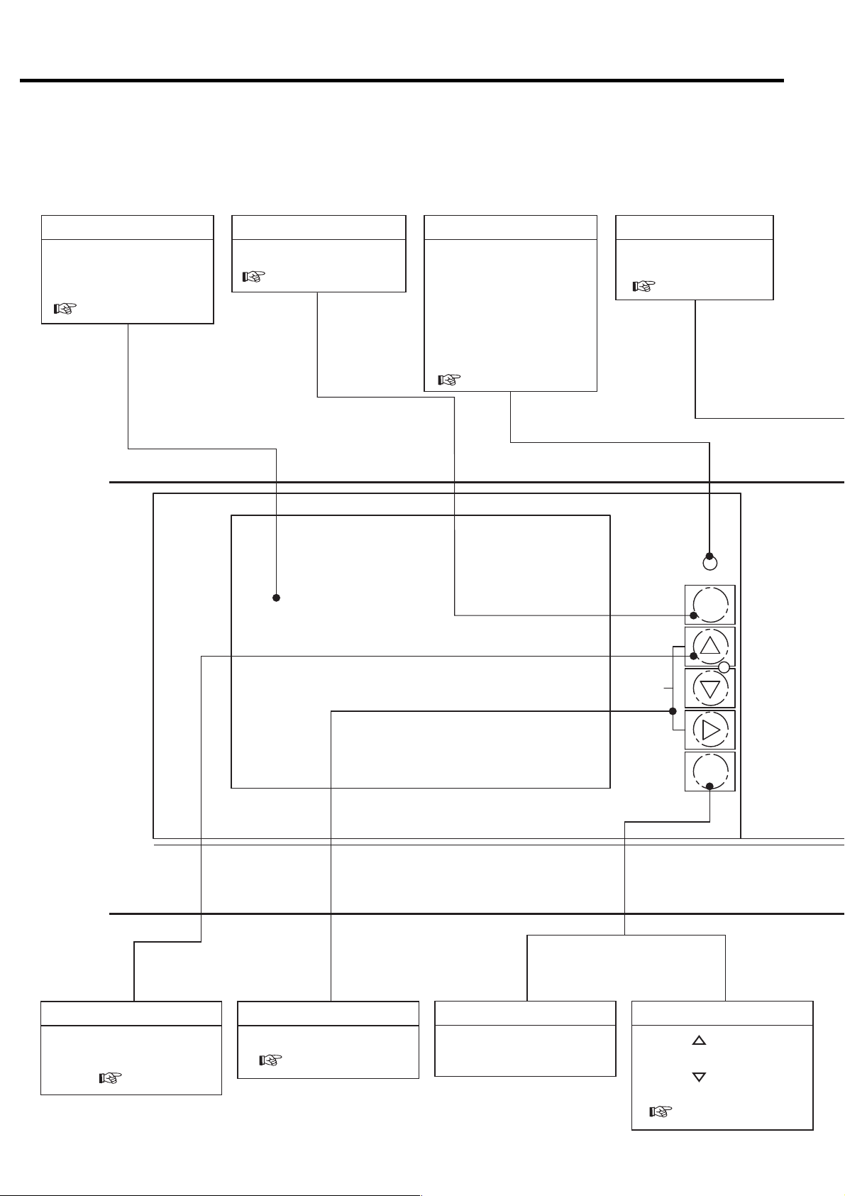
3. OPERATING PROCEDURE
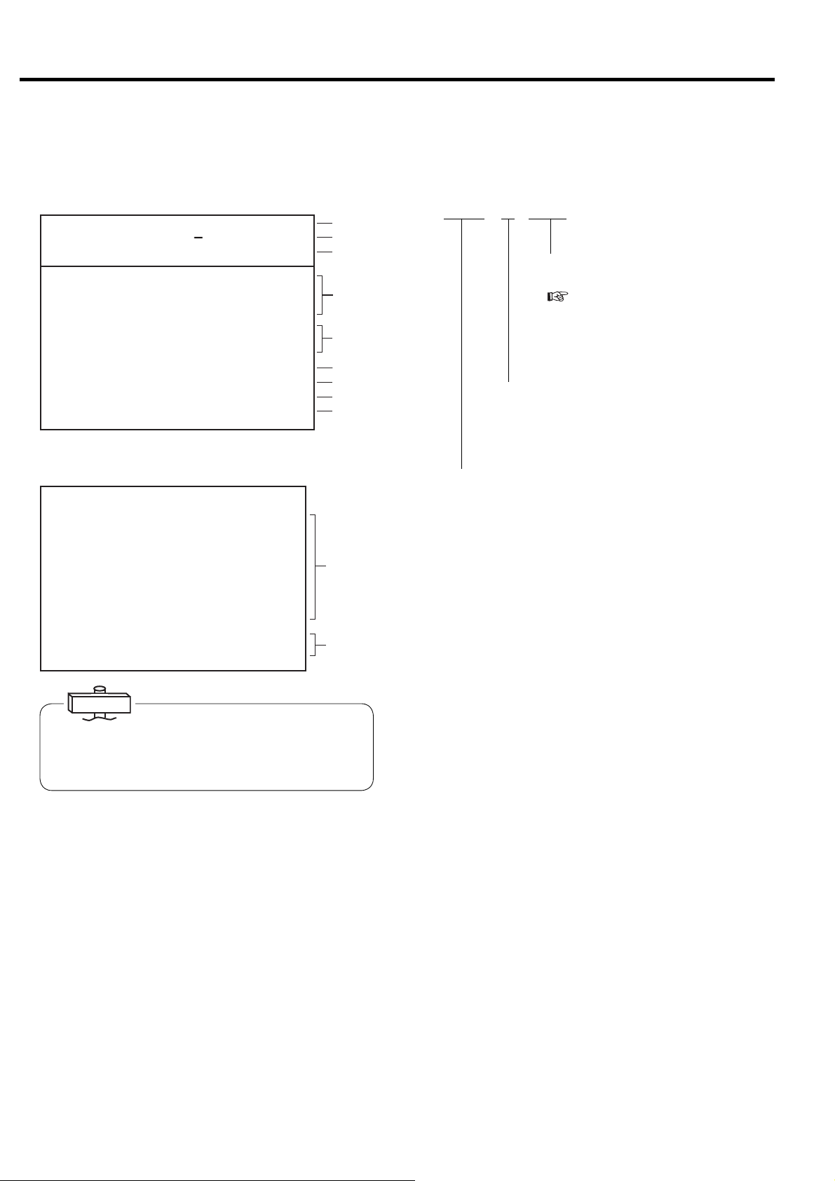
3.1 Instrument Panel
LCD monitor
Displays the operation data,
various settings, shutdown/
alarm information, etc.
( 3.3)
MONITOR Button RESET Button
Switches the monitor display.
( 3.3.1)
AUTO light (yellow)
ON (glowing) when an
automatic operation (an
AUTO operation, a scheduling operation, or lead/lag
operation) is activated.
ON (blinking) when external
calendar or scheduling
operation is abnormal.
( 3.3.3, 3.3.5)
Resets SHUTDOWN
and ALARM screens.
( 3.3.3)
AUTO
MONITOR
MENU Button
Displays the menu screen.
Also used to move the
cursor. ( 3.3.4)
+/- UP DOWN Button
Moves the cursor.
( 3.3.4)
MONITOR
Saves any adjusted set
points.
SET Button
MENU
+/−
UP/
DOWN
SET
Contrast adjustment
SET + [ ] buttons:
Increases brightness.
SET + [] buttons:
Decreases brightness.
( 3.3.6)
12
Digital Monitor
Used for basic settings as well
as other various settings in
combination with the LCD monitor.
( 3.3.6)
● ALARM light (green): Blinks if
an alarm failure occurs.
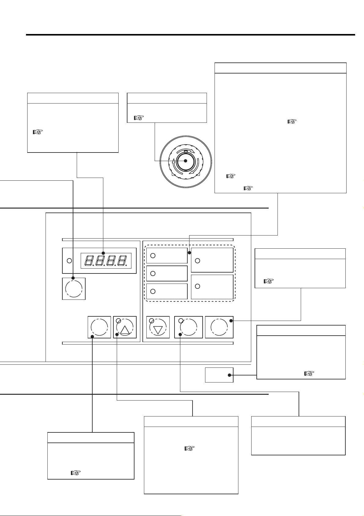
3. OPERATING PROCEDURE [Instrument Panel]
EMERGENCY STOP button
Stops for emergency.
( 3.2.3)
G
E
R
N
E
M
E
S
C
P
T
O
RUNNING MODE Light
● POWER light (yellow): Lights up when the main power
is turned on.
● REMOTE light (green):
ON (glowing) when the REMOTE button is pressed in
order to activate a remote operation.
ON (blinking) when an external remote-operation-
activation switch has been turned on in order to
activate a remote operation. ( 3.4.6)
● LOAD light (yellow): ON (glowing) when the air
compressor is loading.
● AUTO START light (green):
ON (glowing) while the air compressor is in a stop due
Y
to an AUTO operation,lead/lag operation, or
scheduling operation.
ON (blinking) while the air compressor is in a stop due
to a restartable instantaneous power interruption.
( 3.3.3)
● SHUTDOWN light (red): Blinks if a shutdown failure
occurs. ( 3.3.3)
RUNNINGCONTROL
REMOTE
ALARM
[×10h]
FUNC
Press this button to stop the air compressor.
The air compressor will stop after removing the
condensate from the air end.
※This stop button is effective while a stand alone operation.
RESET
REMOTE
STR
SELECT/WIDE
1
LOAD
SHUTDOWN
2
RUNNINGMODE
POWER
AUTOSTART
START
UNLOAD STOP
STOP Button
Stops the compressor
immediately without unloading.
( 3.2.2)
STOP
UNLOAD STOP Button
Stops the compressor in normal
state.
The compressor stops running
after removing the condensate
from the air end. ( 3.2.2)
REMOTE Button
Activates or deactivates a
remote start/stop operation
locally or on the instrument
panel. ( 3.4.6).
SELECT/WIDE Button/Light (Yellow)
Press to confirm the measurement
values, shutdown history, and
setting status. ( 3.4.1, 3.4.2)
To set the ECOMODE [Energy
saving mode] (Fixed speed type
only), hold down the
SELECT/WIDE
button for at least 7 seconds. The
light blinks and ECOMODE is set.
START Button
Starts the air compressor.
The START light turns ON while
air compressor is running.
13
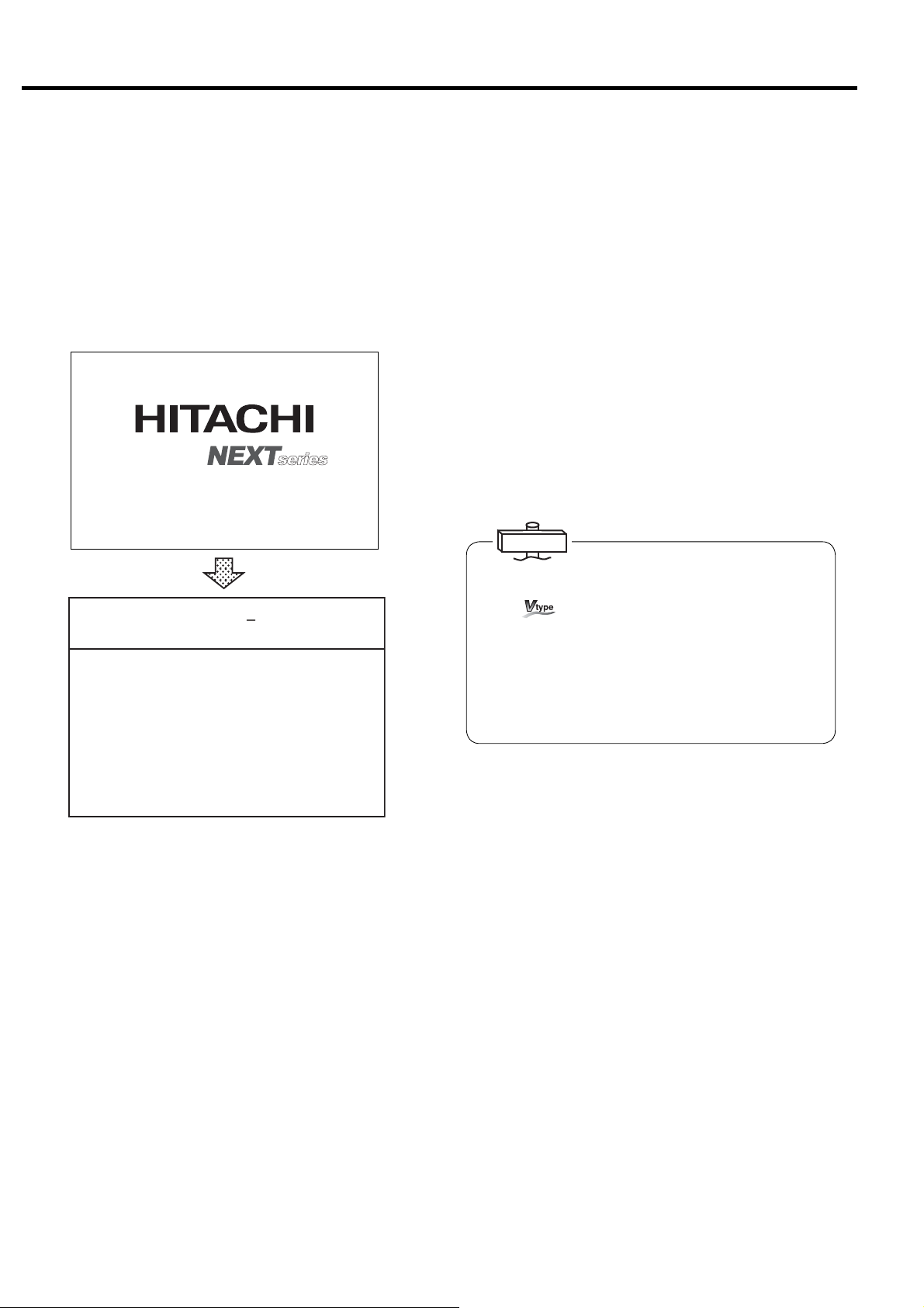
3. OPERATING PROCEDURE [Start/Stop Operation]
3.2 Start/Stop Operation
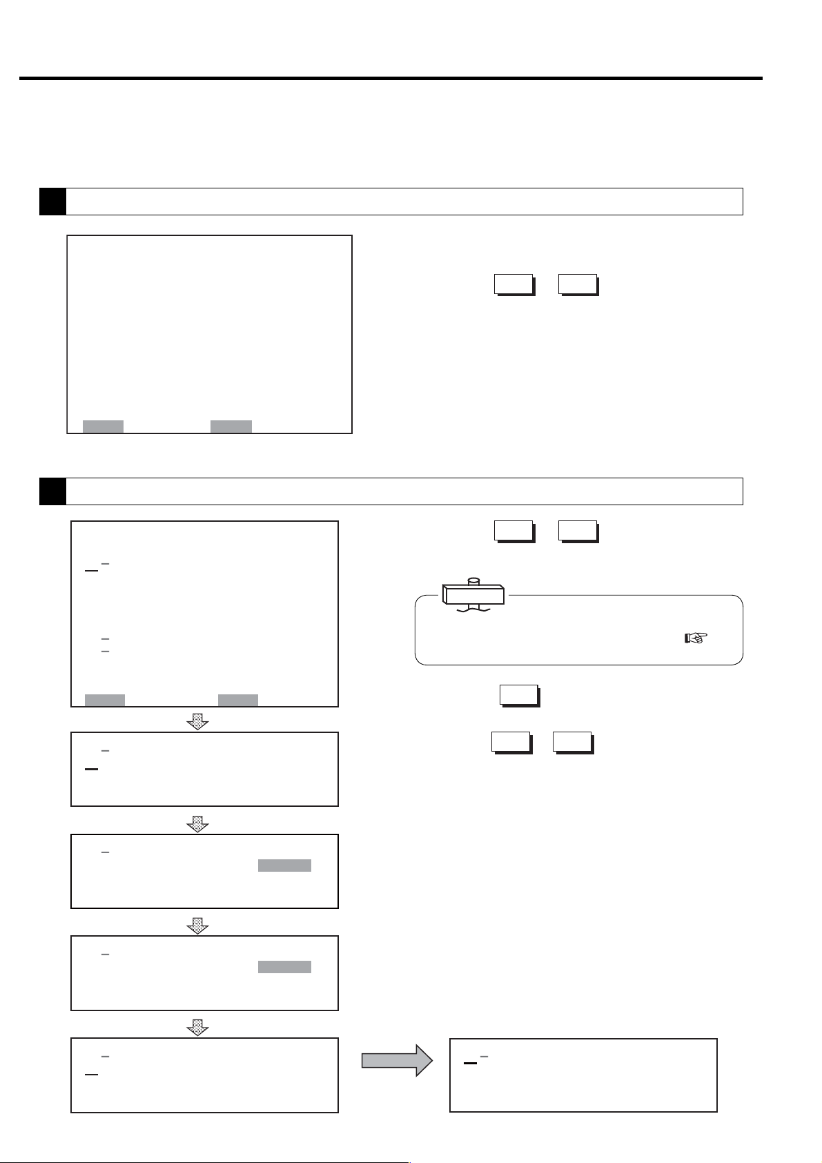
3.2.1 Connecting the Power
When the power is connected, the POWER light turns
ON and the following Hitachi logo display appears on
the LCD. After 5 seconds, monitoring display appears;
it shows operation type, discharge air pressure, total
operating hours, etc.
COMPRESSOR MONITOR
CONTROLLER
5 seconds
㻞㻜㻝㻞䠋㻜㻥䠋㻜㻝 㻝㻥䠖㻜㻞
㼀㼅㻼㻱䠖㼂㻿㻰㻭
㻰㻵㻿䠊㻼㻾㻱㻿㻿䠖 㻢㻣㼜㼟㼕
㻾㼁㻺 㻌㻴㻻㼁㻾䠖 㻝 㻞 㻜䡄
㻸㻻㻭㻰㻌 㻴㻻㼁㻾䠖 㻡㻠 䡄
㻸㻻㻭㻰 㼀 㻵 㻹㻱 㻿 䠖 㻝 㻞 㻟
㻸㻻㻭㻰 㻾㻭㼀㻱 䠖 㻝 㻝䠂
㻸㻻㻭㻰 㼀 㻵 㻹㻱 䠖 㻞 㻠 䡏
㼁㻺㻸㻻㻭㻰 㻌 㼀 㻵㻹㻱 䠖 㻝䡏
㻯㼁㻾㻾㻱㻺㼀 䠖 㻡 㻜䠝
㻲㻾㻱㻽㼁㻱㻺㻯㼅䠖 㻞 㻟 㻚 㻤䠤䡖
㻻㼁㼀㻼 㼁㼀 䠖 㻝 㻠 㻚 㻣 㻼
㻌㻌㻌㻌㻖
䠤
3.2.2 Start/Stop
When the START button is pressed, the START light
turns on and the compressor star ts operating.
When the compressor starts running, the asterisk on
the right side of running hours blinks and running time
starts to be counted.
To stop the operation, press the UNLOAD STOP
button. Operation stops after 5-minute drying of air end
and air piping.
To stop the compressor immediately without
unloading, press the STOP button.
Note) If the STOP button is pressed during unloading,
the compressor stops immediately.
IMPORTANT
(1) The air compressor does not start for 10 second after
power on to secure the safety.
For
15 seconds after power-on, the AUTO START light will
blink up to 10 seconds for operation preparation and
then the compressor starts running.
(2) Make sure that the door is closed before starting the
air compressor.
(3) Buttons, such as START/STOP/RESET function shall
be pressed for more than 0.3 seconds.
, if the START button is pressed within 10 to
3.2.3 Emergency Stop
※ The asterisk blinks when the clock and total
running hours are active.
If phase is reversed, “Connection Error: Reverse
Phase” will be displayed on the LCD monitor as a
setting/connection check message. In this case,
exchange 2 out of the 3 main power cables. If the air
compressor has control transformer in the control
panel, Open Phase is indicated as Reverse Phase. So
check the power cable connection of T Phase.
In case of open phase, “Connection Error: Open
Phase” will be displayed on the LCD monitor. In this
case, check the power cables.
Pressing EMERGENCY STOP button, the DSP
compressor immediately stops.
This switch should only be pressed in emergency.
The compressor can not be restarted until the switch is
manually reset.
Turn the switch knob clockwise and press the RESET
button to reset.
14
3. OPERATING PROCEDURE [How to Use the Liquid Crystal Display (LCD)]
3.3 How to Use the Liquid Crystal Display (LCD)
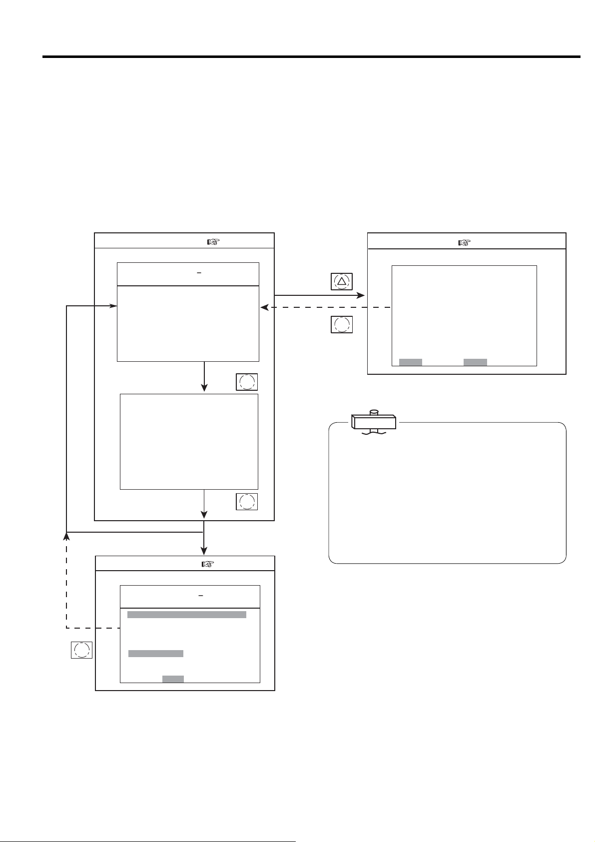
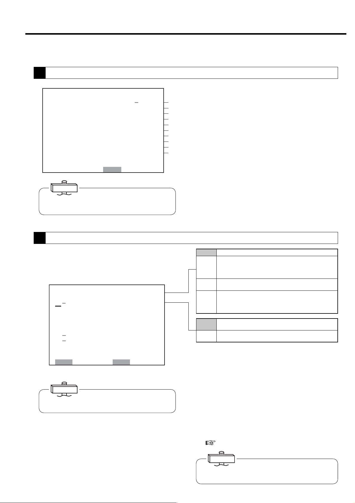
3.3.1 How to Move between the Various Displays
■Monitoring Displays
There are three monitoring displays as shown
below. This monitoring display is the top screen.
The monitoring display switches every time the
MONITOR button is pressed.
■Monitoring Display ( 3.3.2)
Monitor display 1
㻞㻜㻝㻞䠋㻜㻥䠋㻜㻝 㻝㻥䠖㻜㻞
㼀㼅㻼㻱䠖㼂㻿㻰㻭
㻰㻵㻿䠊㻼㻾㻱㻿㻿䠖 㻢㻣㼜㼟 㼕
㻾㼁㻺 㻌㻴㻻㼁㻾䠖 㻝㻞 㻜 䡄
㻸㻻㻭㻰 㻴㻻㼁㻾䠖 㻡 㻠䡄
㻸㻻㻭㻰 㼀 㻵 㻹㻱 㻿䠖 㻝 㻞 㻟
㻸㻻㻭㻰 㻾㻭㼀㻱 䠖 㻝 㻝䠂
㻸㻻㻭㻰 㼀 㻵 㻹㻱 䠖 㻞 㻠 䡏
㼁㻺㻸㻻㻭㻰 㼀 㻵 㻹㻱 䠖 㻝䡏
㻯㼁㻾㻾㻱㻺㼀 䠖 㻡 㻜䠝
MONITOR
㻲㻾㻱㻽㼁㻱㻺㻯㼅䠖 㻞 㻟 㻚 㻤䠤䡖
㻻㼁㼀㻼 㼁㼀 䠖 㻝 㻠 㻚 㻣
Monitor display 2
㻞㻜㻝㻞䠋㻜㻥䠋㻜㻝 㻝㻥䠖㻜㻞
㻼㻾㻱㻿㻿㼁㻾㻱
㻵㻺㼀㻿㼀㻳䠊㻼䠖 䚷䚷㻞㻥㼜㼟 㼕
㻻㻵㻸㻌㻼㻾㻱㻿䠖 㻌㻌 㻝㻡㼜㼟 㼕
㻯㻸㼀䠊㻼㻾㻱㻿䠖 㻖䠊㻖㻖 㼜 㼟 㼕
㼀㻱㻹㻼㻱㻾㻭㼀㼁㻾㻱
㻰㻵㻿䠊㼀㻱㻹㻼㻝䠖 㻟㻞㻜䉣
㻰㻵㻿䠊㼀㻱㻹㻼㻞䠖 㻟㻝㻟㻤䉣
㻻㻵㻸㻌㼀㻱㻹㻼䠖 㻟㻣䉣
㻯㻸㼀䠊㼀㻱㻹㻼䠖 㻖㻖㻖䉣
㻞㻺㻰 㻌 㻿㼁㻯㼀䠊㼀䠊䠖 㻜㻤 䉣
㻹㻭 㻵 㻺㼀 㻱㻺 㻭㻺㻯㻱
㻴㻾䠊㼀㻻㻌㻹㻭㻵㻺㼀䠖 㻜㻜㻜㻜䡄
㻺㻱㼄㼀㻌 㻹㻭 㻵㻺㼀䠖 㻖㻖㻖㻖
■Message Display ( 3.3.3)
Monitor display 3
㻞㻜㻝㻞䠋㻜㻥䠋㻜㻝 㻝㻥䠖㻜㻞 㻖
㼀㼅㻼㻱䠖㼂㻿㻰㻭
㻰㻵㻿䠊㻼㻾㻱㻿㻿䠖 㻢㻣
䠘㻿 㻴 㼁 㼀 㻰 㻻 㼃 㻺䠚
㻯㻻㻻㻸 㻭㻺㼀 䠖
㻻㻵㻸䠖
㻞䠪㻰㻌 㻿㼁㻯㼀䠊㼀㻱㻹㻼
㻴㻵㻳㻴 㻌㻰㻵㻿䠊㼀㻱㻹㻼䠖
㻯㻻㻺㼀 㻭㻯㼀 㻻㻾 㻌㻱㻾 㻾䠖
㻻㼂㻱㻾 㻸㻻㻭㻰 䠖
㻸㻻㼃㻌㼃䠊 㻵㻺 㼀㻿㼀㻳 㻌 㻼䠊
㻰 㻾 㼅 㻱 㻾 㻌㻌㻌㻌 㼃 䠋 㻻 㻌 㻿 㻱 㻼 䠊
㻱㻸㻱㻹㻱㻺㼀
㻼㼞㼑㼟㼟㻾㻱㻿㻌 㼍㼒 㼠㼑㼞 㻌㻯㻴㻷䠊
㼀㼁
MONITOR
MONITOR
㻌
㻌
䡇䠳
㻝
㼜㼟㼕
■ Menu Displays
Follow the bottom line message on the display.
■ Menu Screen ( 3.3.5)
Function Menu Display
MENU
MONITOR
㼇㻲㼁㻺㻯㼀㻵㻻㻺 㻹㻱㻺㼁㼉
㻝䠊㻮㻭㻿 㻵 㻯 㻿㻱㼀㼁㻼
㻞䠊㻹㼁㻸㼀 㻵 㻙 㼁㻺㻵 㼀
㻟䠊㻯㻭㻼㻭㻯㻵 㼀㼅 㻯㻻㻺㼀㻾㻻㻸
㻠䠊㻿㻯㻴㻱㻰㼁㻸㻱
㻡䠊㻻㻼㻱㻾㻭㼀 㻵㻻㻺 㻰㻭㼀㻭
㻢䠊㻸㻻㻭㻰 㻰㻭㼀㻭
㻣䠊㻭㻸㻭㻾㻹 㻴 㻵 㻿㼀㻻㻾㼅
㻤䠊㻿㻴㼁㼀㻰㻻㼃㻺 㻴 㻵 㻿㼀㻻㻾㼅
㻿㻱㼀䠖㻻㻼㻱㻺 㻹㻻㻺䠖㻮㻭㻯㻷
IMPORTANT
About the LCD Backlight
(1) In the event that no button has been used for 10
minutes, the LCD backlight automatically turns OFF for
protection to the display panel. It comes ON again if
any button is pressed, other than the START and STOP
buttons.
(2) If an event happens while the LCD backlight is off, the
backlight automatically turns ON and stays ON as long
as the event exists. Remote and instant stop mode
can't be set by the LCD monitor. Set after referring to
“3.4 How to Use the Digital Monitor.”
■ Message Display
Automatic restart/stop messages after shutdown or
warning occurrence and inspection/maintenance
messages is preferentially displayed in the Monitor
Display 3.
By pressing the MONITOR button here, the display
can be switched but is back to the Monitor Display 3
after approximately 10 seconds.
15
3. OPERATING PROCEDURE [How to Use the Liquid Crystal Display (LCD)]
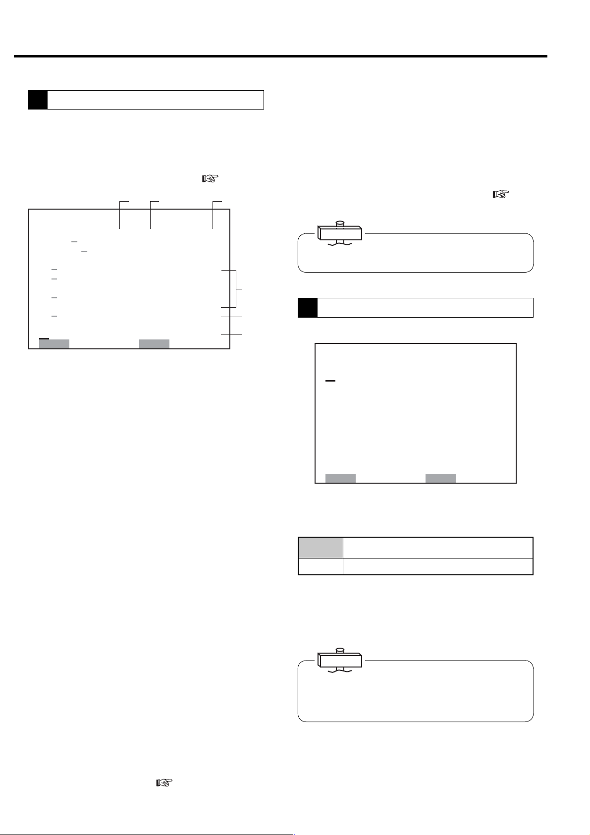
3.3.2 Monitoring Displays
■ Monitor Displays during Normal Operation
Monitor Display 1
㻞㻜㻝㻞䠋㻜㻥䠋㻜㻝 㻝㻥䠖㻜㻞
㼀㼅㻼㻱䠖㼂㻿㻰㻭
㻰㻵㻿䠊㻼㻾㻱㻿㻿䠖 㻢㻣㼜㼟㼕
㻾㼁㻺 㻌㻴㻻㼁㻾䠖 㻝㻞㻜䡄
㻸㻻㻭㻰㻌 㻴㻻㼁㻾䠖 㻡 㻠䡄
㻸㻻㻭㻰 㼀㻵㻹㻱㻿䠖 㻝㻞㻟
㻸㻻㻭㻰 㻾㻭㼀㻱 䠖 㻝 㻝䠂
㻸㻻㻭㻰 㼀 㻵 㻹㻱 䠖 㻞 㻠 䡏
㼁㻺㻸㻻㻭㻰 㻌 㼀 㻵 㻹㻱 䠖 㻝䡏
㻯㼁㻾㻾㻱㻺㼀 䠖 㻡 㻜䠝
㻲㻾㻱㻽㼁㻱㻺㻯㼅䠖 㻞 㻟 㻚 㻤䠤䡖
㻻㼁㼀㻼㼁㼀 䠖 㻝 㻠 㻚 㻣䡇
㻹㻭㻿㼀㻱 㻾
Monitor Display 2
㻞㻜㻝㻞䠋㻜㻥䠋㻜㻝 㻝㻥䠖㻜㻞
㻼㻾㻱㻿㻿㼁㻾㻱
㻵㻺㼀㻿㼀㻳䠊㻼䠖 㻌㻌 㻞㻥㼜㼟㼕
㻻㻵㻸㻌㻼㻾㻱㻿䠖 㻌㻌 㻝㻡㼜㼟 㼕
㻯㻸㼀䠊㻼㻾㻱㻿䠖 㻖䠊㻖 㻖㼜 㼟 㼕
㼀㻱㻹㻼㻱㻾㻭㼀㼁㻾㻱
㻰㻵㻿䠊㼀㻱㻹㻼㻝䠖 㻟㻞㻜䉣
㻰㻵㻿䠊㼀㻱㻹㻼㻞䠖 㻟㻝㻟㻤䉣
㻻㻵㻸㻌㼀㻱㻹㻼䠖 㻟㻣䉣
㻯㻸㼀䠊㼀㻱㻹㻼䠖 㻖㻖 㻖䉣
㻞㻺㻰㻌㻿㼁㻯㼀䠊㼀䠊䠖 㻜㻤䉣
㻹㻭 㻵 㻺㼀㻱 㻺㻭 㻺㻯㻱
㻴㻾䠊㼀㻻㻌㻹㻭㻵 㻺㼀䠖 㻜㻜㻜㻜䡄
㻺㻱㼄㼀㻌 㻹㻭 㻵 㻺㼀䠖 㻖 㻖 㻖 㻖
㻝
(1)
㻖
(2)
(3)
VSDA * SAVE
Indicates ECOMODE is activated for
㻖
(4)
(5)
(6)
㼃
(7)
(8)
(9)
Displayed when stop is limited for AUTO
operation (Standard: no symbol)
fixed speed type.
3.4.8)
(
INTE : Indicates fixed speed type used the standard, 2-step
䠆
control system.
AUTO : Indicates fixed speed type used the automatic motor
stop/restart capacity control system.
(10)
VSDB : Indicates Vtype without the AUTO capacity control.
VSDA : Indicates Vtype with the AUTO capacity control
(standard setting for Vtype).
EXIT : Indicated the external capacity control is used.
(11)
MR : Indicates multi unit control system through the
communication is used
IMPORTANT
“CURRENT” reading is an approximate S-phase Amp
reading.
“OUTPUT” reading is an approximate calculated power
reading.
(1) Indicates current time. An asterisk blinks.
(2) Indicates the control state.
(3) Indicates a discharge pressure (DIS.PRESS)
(4) Indicates total running hours (RUN HOUR), total
loaded hours (LOAD HOUR), and total number of
loads (LOAD TIMES).
Blinking asterisk means counting the running
hours.
(5) Indicates a percentage of load to unload of the DSP
air compressor (LOAD RATE).
For Vtype, the rate is calculated based on only
frequency. Indicates “***”, if PQ wide mode is
selected.
(6) Indicates the amperage current of the package
input (CURRENT).
(7) Indicates the operating frequency of the main motor
(FREQUENCY).
(8) Indicates “***” for this air compressor.
(9) Indicates (MASTER), when the air compressor is
master in lead-lag operation.
(10) Indicates each pressure and temperature. “***”
indicates not in use.
(11) Indicates the number of hours until the next
maintenance service (HR. TO MAINT), and the
next maintenance type (NEXT MAINT).
16
3. OPERATING PROCEDURE [How to Use the Liquid Crystal Display (LCD)]
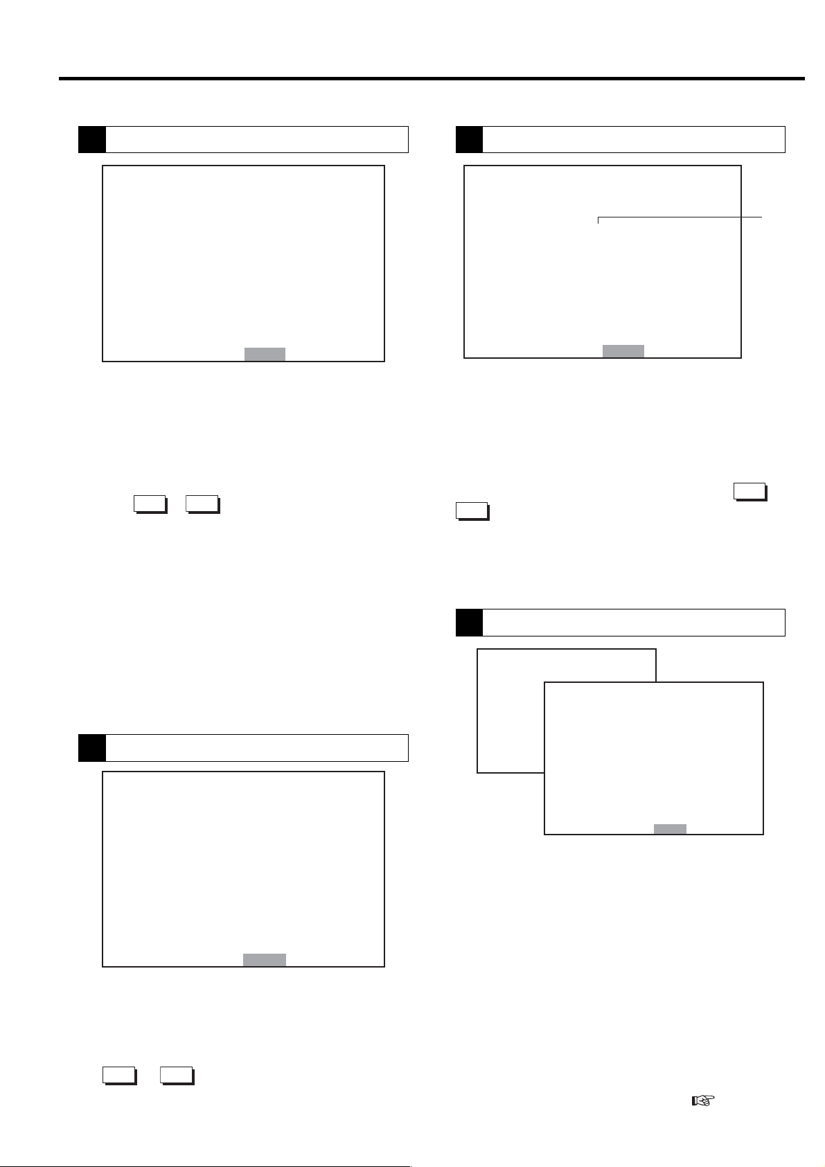
3.3.3 Message Displays
■ Shutdown Messages
① When the shutdown occurs for the compressor, the SHUTDOWN light and shutdown contents on the LCD
monitor (contents are displays on the left side and details are displayed on the right side) blink and the
compressor stops running. There are 2 types of screens for shutdown: SHUTDOWN and FAILURE.
㻞㻜㻝㻞䠋㻜㻥䠋㻜㻝 㻝㻥䠖㻝㻥 㻖
㼀㼅㻼㻱䠖㼂㻿㻰㻭
㻰㻵㻿䠊㻼㻾㻱㻿㻿䠖 㻌㻌 㻢㻣㼜㼟㼕
䠘㻿 㻴 㼁 㼀 㻰 㻻 㼃 㻺䠚
㻯㻻㻻㻸 㻭㻺 㼀 䠖
㻻㻵㻸䠖
㻞䠪㻰 㻌 㻿㼁㻯㼀䠊㼀㻱㻹㻼
㻴㻵㻳㻴 㻌㻰㻵㻿䠊㼀㻱㻹㻼䠖
㻯㻻㻺㼀 㻭㻯 㼀㻻㻾 㻌㻱㻾㻾 䠖
㻻㼂㻱 㻾㻸 㻻㻭㻰 䠖
㻸㻻㼃㻌㼃䠊 㻵 㻺㼀㻿㼀㻳 㻌 㻼䠊
㻰 㻾 㼅 㻱 㻾 㻌㻌㻌㻌 㼃 䠋 㻻 㻌 㻿 㻱 㻼 䠊
㻱㻸㻱㻹㻱㻺㼀
㻼㼞㼑㼟㼟㻾㻱㻿㻌 㼍 㼒 㼠㼑 㼞 㻌㻯㻴㻷䠊
㼀㼁
㻌
(Example)
When the air compressor stops running with blinking
SHUTDOWN and OVERLOAD, it indicates the thermal relay
trip by overload.
2012䠋 01䠋 01 19䠖 19 *
TYPE䠖 VSDA
DIS䠊 PRESS䠖 46ps i
䠘 FA I LURE䠚
SYSTEM ERR䠖
SYSTEM RETRY
PCB ERR䠖
PRESS䠊 SNSR ERR䠖
TEMP䠊 SNSR ERR䠖 1
D 䡅 sconnect power
snd contact
di st r 䡅 but o r
(Example)
When the air compressor stops running with blinking FAILURE
and TEMP.SNSR ERR, the temperature sensor 1 is
disconnected.
② Take the proper corrective action, and press the RESET button.
For further information,
Section 4.
■ Alarm Messages
① When the alarm occurs for the air compressor, the ALARM light and contents / details displayed on alarm screen
on the LCD monitor blink and operation continues. There are 2 types of alarm screens: ALARM and PROBLEM.
㻞㻜㻝㻞䠋㻜㻥䠋㻜㻝 㻝㻥䠖㻝㻥 㻖
㼀㼅㻼㻱䠖
㻰㻵㻿䠊㻼㻾㻱㻿㻿䠖 䚷䚷㻢㻣㼜㼟㼕
䠘㻭 㻸 㻭 㻾 㻹䠚
㻰㻵㻿䠊㼀㻱㻹㻼䠖䠄㻌 㻌 㻌 䠅㻖㻖㻖䉣
㻻㻵㻸㻌㼀㻱㻹㻼䠖 㻖㻖㻖䉣
㻸㻻㼃㻌 㻻䠊㻼䠊䠖 㻖 㻖 㼜 㼟 㼕
㻯㻸㼀䠊㼀㻱㻹㻼䠊䠖 㻖 㻖 㻖䉣
㻸㻻㼃㻌 㻯㻸 㼀䠊㻼䠖 㻖 㻖 㼜 㼟 㼕
㻞䠪㻰㻙㻿䠊㼀㻱㻹㻼 㻌 㻲 㻵 㻺 㻙㼀
㻸㻻㼃㻌㼃䠊 㻸㻻㼃㻌 㻻 㻵 㻸
㻰㻾㼅㻱㻾 㻭㻵 㻾 㻌㻲㻵 㻸㼀㻱㻾
㻸䠊㻯㻻㼁㻺㼀㻌 㻻㼂㻱㻾 㻌㼃䠋㻻㻌 㻿䠊
㻼㼞㼑㼟䡏㻾㻱㻿 㼍㼒 㼠㼑 㼞 㻌㻯㻴㻷䠊
㻿㻰㻭㻌 㻌㻌 㻌㻌㻌
㼂
(Example)
When the ALARM and AIR FILTER blink, it indicates air
intake filter clogs.
㻞㻜㻝㻞䠋㻜㻥䠋㻜㻝 㻝㻥䠖㻝㻥 㻖
㼀㼅㻼㻱䠖 㼂㻿㻰㻭㻌
㻰㻵㻿䠊㻼㻾㻱㻿㻿䠖 䚷䚷㻢㻣㼜㼟 㼕
䠘㻼 㻾 㻻 㻮 㻸 㻱 㻹䠚
㻯㻻㻺㻺 㻱㻯 㼀 㻵 㻻㻺 㻌 㻱 㻾㻾 䠖㻌 㻌 㻌
㻾㼑㼏㼛㼚㼚㼑㼏㼠 㻌 㼜㼛㼣㼑 㼞䠊
㻹㼁㻸 㼀 䠥 㻙 㼁 㻿 㻱 㼀 㻱 㻾㻾
㻿㻯㻴㻱㻰㼁㻸㻱 㻌 㻿㻱㼀 㻌 㻱㻾㻾
㻯㻻㻹䠊㻱㻾㻾㻌㻿㼀㻻㻼䠖㻌㻌㻌㻌㻌
㻯㻻㻹䠊㻱㻾㻾㻌㻭㻸㻹䠖 㻌㻌㻌㻌㻌
㻮㻭㼀㼀 㻱㻾㼅 㻌㻻㼁㼀
㻼㼞㼑㼟㼟㻾㻱㻿 㼍㼒 㼠㼑 㼞 㻯 㻴㻷䠊
㻌㻌 㻌㻌㻌
(Example)
When the PROBLEM and BATTERY OUT blink, it indicates
the battery replacement period.
② Take the proper corrective action, and press the RESET button.
For further information,
Section 4.
NOTE) Malfunction detection of water failure (LOW W) is available for only water cooled single stage compressor.
Malfunction detection of dryer (DRYER) is available for only built-in dr yer models. Malfunction detection of
oil water separator (W/O SEP) is not available.
17

3. OPERATING PROCEDURE [How to Use the Liquid Crystal Display (LCD)]
■ Messages of Automatic Stop Display
When the air compressor stops automatically, the AUTO START light glows or blinks and RESTART display
appears. After the air compressor restarts, monitoring display appears again.
● SCHEDULED STOP: Schedule operation setting
<AUTO light glows>
This indicates that the air compressor has been
㻞㻜㻝㻞䠋㻜㻥䠋㻜㻝 㻝㻥䠖㻜㻞 㻖
㼀㼅㻼㻱䠖 㼂㻿㻰㻭㻌
㻰㻵㻿䠊㻼㻾㻱㻿㻿䠖 䚷䚷㻢㻣㼜㼟㼕
䠘㻾 㻱 㻿 㼀 㻭 㻾 㼀䠚
㻌㻌 㻌㻌㻌
automatically stopped by a pre-set time.
The air compressor starts automatically when the
pre-set restart time comes.
㻾㻱㻿㼀㻭㻾㼀 㻭㼀 䠖 䠆䠆䠖䠆䠆
㻾㻱㻿㼀㻭㻾㼀 㼃㻭 㻵 㼀 䠖 㻌 㻞 㻣䡏
㻺㻻㼃䠈㻿㼀 㻻㻼㻼 㻱 㻰 䠞䠵䠖
㻿㻯㻴㻱㻰㼁㻸㻱 㻿 㼀㻻㻼
㻭㼁㼀㻻㻹㻭㼀 㻵 㻯 㻿 㼀㻻㻼
㻰㻾㼅㻱㻾 㻼㻾 㻱㻿㼀㻭㻾 㼀㻱㻰
㻰㼁㻭㻸䠋㻮㻭㻯㻷㼁㻼
㻵㻼㻵 㻌㻾㻱㻿㼀㻭㻾㼀
㻯㼀㻸㻾䠊㻾㻱㼀㻾㼅
● LEAD/LAG OPERATION STOP (option)
<AUTO light glows>
This indicates that the air compressor is waiting for
starting as a slave unit in a two-unit-alternate
operation or a backup operation.
● DRYER PRESTARTED (Built-in dryer model)
<AUTO light blinks>
This indicates that the dryer has started and air
compressor is waiting for the start. The RESTART
WAIT field shows an expected waiting period until
the air compressor can start in seconds.
● AUTO OPERATION
<AUTO light glows>
This indicates that the air compressor in AUTO
operation has stopped due to the low air demand and
is waiting for restarting when demand is needed.
The RESTART WAIT field shows an expected
waiting period until the air compressor can restart in
seconds.
18
● INSTANT STOP / RETRY (Retry is for only Vtype)
<AUTO light blinks>
For both fixed speed and Vtype, this indicates that
the air compressor has stopped due to an
instantaneous power interruption (IPI). The
RESTART WAIT field shows an expected waiting
period until the air compressor can restart in
seconds.
For Vtype, this indicates that the air compressor has
stopped due to the variable speed drive failure and is
waiting for restart as well. The RESTART WAIT
field shows an expected waiting period until the air
compressor can restart in second.
3. OPERATING PROCEDURE [How to Use the Liquid Crystal Display (LCD)]
■ Maintenance Notice Messages
① Periodical maintenance
A maintenance date is determined by the amount of total operating hours or an elapsed calendar period, whichever
comes first. When the maintenance date or time arrives, the maintenance notice message appears on the display
under the heading of MESSAGE.
This function is only for the notice and is not output externally.
The consumable parts for the suction throttle valve shall be replaced this maintenance notice or L COUNT OVER
appears, whichever comes first.
㻞㻜㻝㻞䠋㻜㻥䠋㻜㻝 㻝㻥䠖㻜㻞 㻖
㼀㼅㻼㻱䠖 㼂㻿㻰㻭㻌
㻰㻵㻿䠊㻼㻾㻱㻿㻿䠖 㻌㻌 㻢㻣㼜㼟 㼕
䠘㻹㻱㻿㻿㻭㻳㻱䠚
㻹㻭 㻵 㻺 㼀䠊 䠖㻝 㼅 㻱 㻭㻾㻌 㻌
㻹㻭 㻵 㻺 㼀䠊䠯䠟䠤䠡䠠䠱㻸䠡 䠖 㻭
㻼㼞㼑㼟㼟㻿㻱㼀㻌㼍 㼒 㼠 㼑㼞 㻌㻯㻴㻷䠊
㻹㻭 㻵 㻺 㼀䠊㻯㻻㻹㻼 㻸 㻱 㼀 㻱㻰
㻿㼃 㻵 㼀㻯㻴㻱 㻰 㻌 㼀㻻 㻌 㻸㻻㻯㻭㻸
㻵㻺㻌㻻㼂㻱㻾䠮㻵㻰㻱 㻹㻻㻰㻱
㻵㻺㻌㼁㻺㻸㻻㻭㻰㻌㻿㼀㻻㻼
㻿㼃 㻵 㼀㻯㻴㻱 㻰 㻌 㼁 㻌 㻹㻻㻰㻱
㻌㻌 㻌㻌㻌
(1)
(2)
(3)
0.5 year, 1.5 years,
2.5 years, 3.5 years,
4.5 years, 5.5 years
1 year, 5 years Yearly + half-yearly
2 years, 4 years 2-yearly + yearly + half-yearly
3 years 3-yearly + yearly + half-yearly
6 years, overhaul 6-yearly + 3-yearly + 2-yearly + yearly + half-yearly
A
Standard Maintenance Schedule (A) (for yearly 8,000-or-less operating hours)
B
Standard Maintenance Schedule (B) (for yearly 4,000-or-less operating hours)
Half-yearly
CAUTION
If a message of maintenance notice is displayed, carefully read it and service the air compressor as
instructed by this manual. After servicing the air compressor, press the SET button and hold it down for
more than seven (7) seconds; the MAINT. COMPLETED message appears. After one (1) minute, the
monitor display appears.
Note:
1. MAINTenance can be reset, if the servicing is done earlier than expected and if the remaining operating time to next maintenance is
less than 2,000h in the case of A, 1,000h in the case of B.
2. On the contrary, if the servicing is done after the maintenance notice has appeared, the remaining operating hours to the next
maintenance has been zero until the maintenance is done. After maintenance and resetting the counter, new counting time starts
just after the maintenance notice message has appeared on the display.
② Other Message Displays
(1) SWITCH TO LOCAL
If set to local by remote operation following
shutdown restoration, the air compressor will
automatically return to local operation in case of
a shutdown, and the message will be displayed
for 1 minute. (
3.4)
(2) IN OVERRIDE MODE.
Indicates that the compressor is in override
mode.
(3) IN UNLOAD STOP
Blinks when the UNLOAD STOP button is used.
The air compressor unloads for 5 minutes and
then stop.
19
3. OPERATING PROCEDURE [How to Use the Liquid Crystal Display (LCD)]
3.3.4 How to Move within a Menu Display and to Change a Setting
The method and procedure for altering settings is displayed using the following as an example.
How to MOVE within a [FUNCTION MENU] Display
1
[FUNCTION MENU]
1 䠊 BAS I C SE T UP
2 䠊 MUL T I - UN I T
3 䠊 CAPAC I T Y CONTROL
4 䠊 SCHEDULE
5 䠊 OPE RA T I ON DAT A
6 䠊 LOAD DATA
7 䠊 ALARM HI STORY
8 䠊 SHUTDOWN HI STORY
or 2 is appeared
② Press the
desired item number.
③ Press the SET button to open the related setting
display.
The following explanation uses [MULTI-U SETTING
display] as an example.
① Press the MENU button when the monitor display 1
SET䠖 OPE N MON䠖 BACK
How to Select or Change a Setting within a Setting Display
2
㼇㻹㼁㻸㼀㻵㻙㼁㻌㻿㻱㼀㼀㻵㻺㻳㼉
① Press the
desired item number.
㻝
㻹㻻㻰 㻱 䠖 㻳㻸
㻞䠊㻰㼁㻭㻸 㻌 㼀 㻵 㻹㻱䠖 㻌 㻤䠊
㻟䠊㻹㻱㼀㻴㻻㻰䠖 㻭㻼
㻠䠊㻿㼃㻵㼀㻯㻴㻻㼂㻱㻾䠖 㻜㻝㻡 㼟
㻡䠊㻮㻭㻯㻷㼁㻼䠖 㻣㻼
㻢䠊㼁㻺㻸㻻㻭㻰䠖 㻟㻼㻿㼕
㻭㻸㼀䠊㼀 㻵㻹㻱䠖㻌 㻠㻤 㻜㻹 㻵 㻺
㻣
㻯㻻㻺㼀 㻾㻻 㻸 㻹㻻㻰 㻱 䠖 㻮
㻤
㻌㻿㻺
㻻㼂㻾 㻾㻸
㻜㼔
㻿㼕
IMPORTANT
Item number with a dash “-“ cannot be selected on LCD
monitor. It can be selected from digital monitor. (
How to Use the Digital Monitor for the detail.)
△
△
or
or
▽
buttons to move to the
buttons to move to the
▽
3.4
㻿㻱㼀䠖㻿㼀㻻㻾㻱 㻌 㻹㻻㻺䠖㻮㻭㻯㻷
①
㻝 㻹㻻㻰 㻱 䠖
㻞䠊㻰㼁㻭㻸 㻌 㼀 㻵 㻹㻱䠖 㻌 㻤䠊㻜 㼔
㻟䠊㻹㻱㼀㻴㻻㻰䠖
㻠䠊㻿㼃 㻵 㼀㻯㻴㻻㼂㻱㻾䠖 㻜㻝㻡㼟
㻻㼂㻾 㻾㻸
㻳㻸㻿㻺
㻭㻼
②
㻝 㻹㻻㻰 㻱 䠖
㻞䠊㻰㼁㻭㻸 㻌 㼀 㻵 㻹㻱䠖 㻌 㻤䠊㻜 㼔
㻟䠊㻹㻱㼀㻴㻻㻰䠖
㻠䠊㻿㼃 㻵 㼀㻯㻴㻻㼂㻱㻾䠖 㻜㻝㻡㼟
㻻㼂㻾 㻾㻸
㻳㻸㻿㻺
㻭㻼
③
㻝 㻹㻻㻰 㻱 䠖
㻞䠊㻰㼁㻭㻸 㻌 㼀 㻵 㻹㻱䠖 㻌 㻡䠊㻜 㼔
㻟䠊㻹㻱㼀㻴㻻㻰䠖
㻠䠊㻿㼃 㻵 㼀㻯㻴㻻㼂㻱㻾䠖 㻜㻝㻡㼟
㻻㼂㻾 㻾㻸
㻳㻸㻿㻺
㻭㻼
④
㻹㻻㻰 㻱 䠖
㻝
㻞䠊㻰㼁㻭㻸 㻌 㼀 㻵 㻹㻱䠖 㻌 㻡䠊㻜 㼔
㻟䠊㻹㻱㼀㻴㻻㻰䠖
㻠䠊㻿㼃 㻵 㼀㻯㻴㻻㼂㻱㻾䠖 㻜㻝㻡㼟
㻻㼂㻾 㻾㻸
㻳㻸㻿㻺
㻭㻼
② Press the
button to move to the desired
▽
setting field.
③ Press the
△
or
buttons until the desired
▽
setting appears.
④ Press the SET button to return to the item number.
⑤ Press the SET button again to return to the item
number 1. This saves the changed setting.
Press the MONITOR button to return to the
[FUNCTION MENU] display. Press the MONITOR
button again to view the monitoring display.
㻝 㻹㻻㻰 㻱 䠖
⑤
㻞䠊㻰㼁㻭㻸 㻌 㼀 㻵 㻹㻱䠖 㻌 㻡䠊㻜 㼔
㻟䠊㻹㻱㼀㻴㻻㻰䠖
㻠䠊㻿㼃 㻵 㼀㻯㻴㻻㼂㻱㻾䠖 㻜㻝㻡㼟
㻻㼂㻾 㻾㻸
㻳㻸㻿㻺
㻭㻼
20
3. OPERATING PROCEDURE [How to Use the Liquid Crystal Display (LCD)]
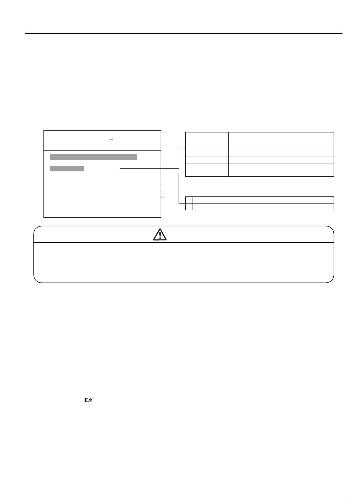
3.3.5 [FUNCTION MENU] - Setting Displays
Model Setting Confirmation
1
㼇㻮㻭㻿㻵㻯 㻿㻱㼀㼁㻼㼉
㼂㻱㻾䠊䠖 㻡䠊㻜
㻿㻱㻾 㻵 㻱㻿 㻺㻭㻹㻱䠖 㻰㻿㻼
㻯㻻㻻㻸 㻵 㻺㻳 㻹㻱㼀 㻴㻻㻰 䠖 㼃㼀㻾
㻺㻻䠊㻻㻲 㻿 㼀 㻭㻳 㻱 䠖 㻌 㻞
㻼㻙㻿㻼㻱㻯䠖 䚷㻝 㻜 㻜㼜 㼟 㼕
㻼䠊㻰㻭㼀㻭䠖 䚷䚷 㻢 㻤 㼜 㼟 㼕
䠟䠰 䠖 㻞 㻡 㻜䠝
㻯㻸㼀䠊㻰㻱㻸㻭㼅䠖 㻌 㻡 㼟
㻵㻼㻵䠖 㻵 㻵 㻵
㻭㻰㻾㻱 㻿㻿 㻺㻻䠊䠖 㻌 㻝
㻹㻻㻺 䠖 㻮 㻭㻯㻷
IMPORTANT
When contacting the local Hitachi distributor, inform
this information as a based setting status.
㻡䠊㻜
①
②
③
④
⑤
⑥
⑦
⑧
⑨
⑩
This display contains software version (VER.), air
compressor series (SERIES NAME), cooling method
(COOLING METHOD), number of air compression
stages (NO. OF STAGE), action against instantaneous
power interruption (IPI) and etc. “** ” means the
setting that is not required.
① Indicates board software version.
② Indicates compressor type.
③ Displays cooling type.
④ Displays the number of compressor stages.
⑤ Displays pressure specification.
⑥ Displays interstage pressure.
⑦ Indicates CT setting value.
⑧ Displays water failure detection conditions for water
cooled compressor.
⑨ Displays status of instantaneous power interr uption
(IPI) restart setting.
⑩
Displays compressor number. (Must be distinguished
by number is using communication function.)
Operation Mode Setting
2
Confirm the settings by lead/lag and multi unit
control (option). These options need wiring
modification. Item number with a dash “-“ cannot be
selected on LCD monitor.
㼇㻹㼁㻸㼀㻵㻙㼁㻌㻿㻱㼀㼀㻵㻺㻳㼉
㻝
㻹㻻㻰 㻱 䠖 㻳㻸
㻞䠊㻰㼁㻭㻸 㻌 㼀 㻵 㻹㻱䠖 㻌 㻤䠊
㻟䠊㻹㻱㼀㻴㻻㻰䠖 㻭㻼
㻠䠊㻿㼃㻵㼀㻯㻴㻻㼂㻱㻾䠖 㻜㻝㻡 㼟
㻡䠊㻮㻭㻯㻷㼁㻼䠖 㻌 㻌 㻌 㻣㼜
㻢䠊㼁㻺㻸㻻㻭㻰䠖 㻌 㻌 㻌 㻟㼜 㼟 㼕
㻭㻸㼀䠊㼀 㻵㻹㻱䠖㻌 㻠㻤 㻜㻹 㻵 㻺
㻣
㻯㻻㻺㼀 㻾㻻 㻸 㻹㻻㻰 㻱 䠖 㻮
㻤
㻿㻱㼀䠖㻿㼀㻻㻾㻱 㻌 㻹㻻㻺䠖㻮㻭㻯㻷
1- MODE:
If using the backup function, switch to the digital
monitor for setting.
Operation mode set on the digital monitor.
IMPORTANT
㻌㻿㻺
㻜㼔
㻻㼂㻾 㻾㻸
㼟㼕
2. DUAL TIME: Alternate operation hours of lead/
lag operation.(Setting range : 0.1 to 99.9 hours;
initial value: 8.0)
3. METHOD: Switching method (overlap or interval)
of lead/lag operation.
4. SWITCHOVER: Switching-over or overlapping
period of lead/lag operation. (Setting range : 5 to
300 seconds; initial value: 15)
SNGL Operates an air compressor independently
Operates by multi roller EX of exclusive use for NEXT
series using communication function.
STPR
By this setting RS485 communication port is effective.
The setting of air compressor number is required.
DUAL
BKUP
OVERLAP
INTERVAL
Operates two air compressors alternately according to
a time schedule. The AUTO light comes ON (glowing).
Operates two air compressors according to a preset
back up pressure. Starts the back up slave unit when
the pressure has dropped to the desired preset back up
pressure. The AUTO light comes ON (glowing)
Slave unit starts, master/slave units overlap in operation
for a preset period, and then master unit stops.
Master unit stops, a non-operating interval passes, and
then slave unit starts.
5. BACKUP: Pressure to start a backup unit in a
backup operation (cut-in (load) pressure – α)
6. UNLOAD: Pressure to unload both the units in a
backup operation (cut-out (unload) pressure – α)
7- ALT. TIME: Displays time remaining until switch for
dual / backup operation. Time is not counted down
when operating 2 units for backup operation. When
operation is stopped, remaining time is maintained.
8- CONTROL MODE: Control mode A or B for Vtype
(
3.3.2). “**” is indicated in fixed speed type.
IMPORTANT
The settings can be memorized while the air compressor
is stopped.
21
3. OPERATING PROCEDURE [How to Use the Liquid Crystal Display (LCD)]
Capacity control
3
This function sets the pressures and times for capacity
control. Two dif ferent combinations (P1 and P2) of
pressures can be used. Item number with dot “ . ” can
be select from LCD monitor. Item number with a dash “
- “ can be selected from digital monitor. (
3.4)
①② ③
㼇㻯㻻㻺㼀㻾㻻㻸 㻿㻱㼀㼀 㻵㻺㻳㼉
㻝䠊㼀㼅㻼㻼㻱䠖㼂㻭 㼎㼎㼎 㼏㼏㼏
㻞䠊䠬
㻟䠊䠬 㻵
㻠
㻡
㻢
㻣
㻤䠊㼀 㻵㻹㻱䠖㻝㻤䠖 㻜㻜 㻞㻞䠖 㻜㻜
㻿㻱㼀䠖㻿㼀㻻㻾㻱 㻌 㻹㻻㻺䠖㻮㻭㻯㻷
㻸㻻㻿㻿䠖 㻖㻖 㼜 㼟 㼕
㻯㻭䠖㻖㻖㻖 㻖㻖䠊㻖䡉㻟
䠄㻯㻻㻺㼀㻾㻻㻸䠋㻯㼁㼀㻙 㻵㻺 㻕
㻼㻝䠖 㻌 㻝 㻜㻜䠋㻌 㻌 㻤㻣㼜 㼟 㼕
㻼㻞䠖 㻌 㻝 㻜㻜䠋㻌 㻌 㻤㻣㼜 㼟 㼕
䠄㼀㻭㻾㻳㻱㼀㻌㻼㻝䠋㻼㻞 㻕
㼀㻭㻾㻳㻱㼀䠖
㻌㻌 㻥㻤䠋㻌㻌 㻥㻤㼜㼟 㼕
㼀㻵㻹㻱㻌㻸㻵㻹㻵㼀䠖 㻜㻟㻜㼟
䠄㻼㻞 㻱㻲㻲㻱㻯ࠥ㼀㻵㼂㻱㻕
④
⑤
⑥
1. Type: Indicates the setting data for capacity control
① Type of capacity control (Cannot be changed from
LCD monitor)
Fixed speed type
I: Indicates the standard, 2-step control.
IP: Indicates the motor stop/restart capacity control
to “I”.
Vtype
VA: Indicates motor stop/restart capacity control is
effective.
VB: Indicates motor stop/restart capacity control is
canceled.
② Pressure setting (Cannot be changed from LCD
monitor)
S-1: Indicates pressure setting 1
S-2: Indicates pressure setting 2
EXT: Indicates external pressure setting
S-A : Indicates pressure setting switches by set time
on ⑥.
③ Option condition and setting.
NUL: Indicates no option.
2. - 3. OPTION: Used for options.
4. - 6. Pressure Setting: ④ Indicates cut-in, cut-out
and target pressure setting 1 and 2 can be confirmed.
Target means target pressure for ECOMODE
7. TIME LIMIT (Fixed speed type only)
⑤ Indicates the time limit of load/unload one-cycle
time for ECOMODE. Load/unload one-cycle time
must be 30 seconds or more. (
3.4.8)
8. TIME: ⑥ Can set the time to use pressure setting 2.
When set the value properly, ② is indicated in “ S-A”. If
the start and stop time is set at same value, pressure
setting 2 is not in use and ② is indicated in S-1. And
pressure setting 1 and 2 can be changed by external
switch. Set the F018 on digital monitor “2”. (
3.4.2
and 3.4.7)
IMPORTANT
The settings can be memorized while the air compressor
is stopped.
Scheduled Operation
4
Allows a standard daily scheduling operation.
㼇㻿㻯㻴㻱㻰㼁㻸㻱㻌㻿㻱㼀㼀㻵㻺㻳㼉
㻝䠊㻹㻻㻰㻱 䠖 㻯㻴㻱㻰㼁㻸㻱
㻿㼀㻭㻾㼀 㻿㼀㻿㻻㻼
䠄㻝䠅㻜㻣䠖㻜㻜㻌 㼅 㻞㻜䠖㻜㻜㻌 㼅
䠄㻞䠅㻜㻜䠖㻜㻜㻌 㻺 㻜㻜䠖㻜㻜 㻌 㻺
䠄㻟䠅㻜㻜䠖㻜㻜㻌 㻺 㻜㻜䠖㻜㻜 㻌 㻺
䠄㻠䠅㻜㻜䠖㻜㻜㻌 㻺 㻜㻜䠖㻜㻜 㻌 㻺
䠄㻡䠅㻜㻜䠖㻜㻜㻌 㻺 㻜㻜䠖㻜㻜 㻌 㻺
㻞䠊㻾㻱㻯㻻㻾㻰 㻝䠖 㻝㻜䠖㻜㻜
㻟䠊㻾㻱㻯㻻㻾㻰 㻞䠖 㻝㻥䠖㻜㻜
㻿㻱㼀䠖㻿㼀㻻㻾㻱 㻌 㻹㻻㻺䠖㻮㻭㻯㻷
This illustration indicates a scheduling operation from 7:00 to
20:00. TIME field indicates a current time of 19:07.
㻝㻥䠖㻜㻣
1. MODE:
OFF Operates without a schedule.
Schedule Operates according to a daily 24- hour calendar.
(1) to (5) : Five Start/Stop Time Patterns
・ START : Star ting Time
・ STOP : Stopping Time
・ Y or N : Starts or Stops as scheduled
IMPORTANT
When the schedule is selected, the AUTO light comes ON
(glowing) if the time setting is valid and ON (blinking) if the
time setting is invalid. The settings can be memorized
while the air compressor is stopped.
2.-3. RECORD1, 2 : This function allows for the
capability to record data over a desired time in a day.
To view the recorded data, refer to “5. Operation data
display” on the next page.
22
3. OPERATING PROCEDURE [How to Use the Liquid Crystal Display (LCD)]
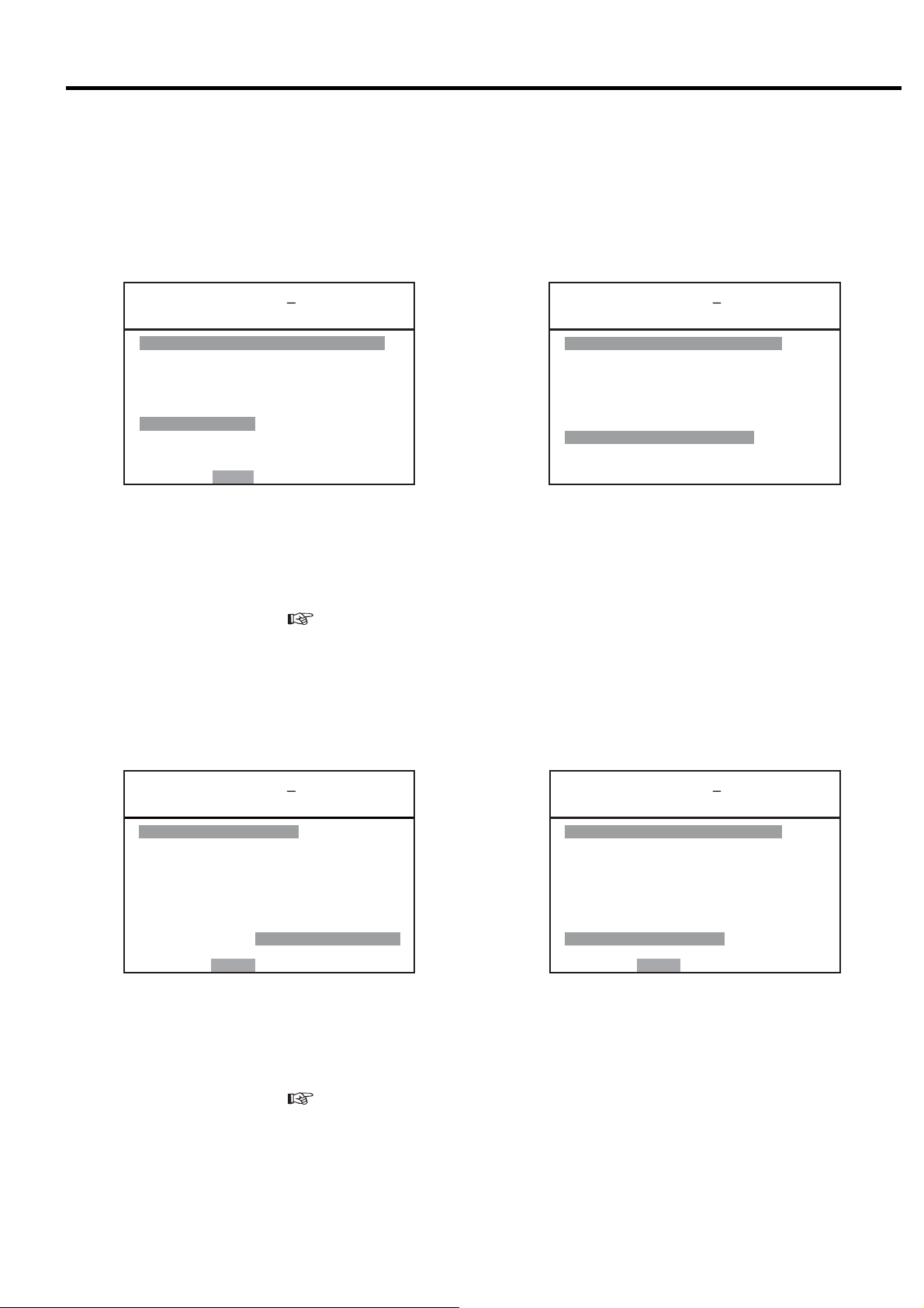
Operation Data Display
5
㼇㻻㻼㻱㻾㻭㼀 㻵㻻㻺 㻰㻭㼀㻭㼉
㻝䠊㻜㻤䠋㻜㻝 㻝 㻜 䠖 㻜 㻜
㻼䠖㻜㻠㻢䚸㻜㻝㻥䚸㻜㻝㻢䚸㻖㻖㻖
㻯䠖 㻜
㼀䠖 㻞㻡䚸 㻟㻟䚸㻖㻖䚸㻖㻖䚸㻖㻖
㻸䠖 㻡㻥䚸㻝㻤䠊㻤
㻞䠊㼍 㼍䠋㼎 㼎 㼏 㼏 䠖㼐㼐
㻼䠖㻖㻖㻖䚸㻖㻖㻖䚸㻖㻖㻖䚸㻖㻖㻖
㻯䠖㻖㻖㻖
㼀䠖㻖㻖㻖䚸㻖㻖㻖䚸㻖㻖䚸㻖㻖䚸㻖㻖
㻸䠖㻖㻖㻖䚸㻖㻖㻖㻖㻖
㻹㻻㻺 䠖 㻮 㻭㻯㻷
Data can be recorded for a maximum of twelve (12)
times. The 13th recorded data is automatically deleted
and the 1st recorded data is added. The most recent
data is arranged at the top of the display. If a change to
these settings is desired, the sampled data before the
settings change will be left as is and the new recorded
data will be applied after the change.
Press the
△
or
▽
button to move within the display.
1. and 2. : Indicates the MONTH / DAY HOUR: MINUTE.
P - Represents a pressure (psi) and indicates from left
to right: Discharge air pressure, Interstage
pressure, Oil pressure, ***
C - Represents an amperage current (A)
T - Represents a temperature (°F) and indicates from
left to right: 1st stage discharge air temperature,
2nd stage discharge air temperature, oil
temperature, ***, 2nd stage suction temperature.
L -Represents a load ratio percentage (%)
Unavailable fields are filled with asterisks.
Load Data Display
6
㼇㻸㻻㻭㻰 㻰㻭㼀㻭㼉
㻝䠊㻜㻤䠋㻜㻝
㻭㼂㻳䠊㻼㻾㻱㻿㻿 䠖 㻌 㻌 㻣 㻡 㼜 㼟 㼕
㻭㼂㻳䠊㻯㼁㻾㻾㻱 㻺㼀 䠖 㻜 㻠 㻜䠝
㻭㼂㻳䠊㻸㻻㻭㻰 㻾㻭㼀㻱䠖㻜㻢㻡䠂
㻭㼂㻳䠊㻼䠫䠳䠡䠮䠖 㻌 㻝 㻣 㻚 㻤 㼗㼃
㻞䠊㻜㻝䠋㻜㻝
㻭㼂㻳䠊㻼㻾㻱㻿㻿 䠖 㻌 㻌 㻣 㻡 㼜 㼟 㼕
㻭㼂㻳䠊㻯㼁㻾㻾㻱 㻺㼀 䠖 㻜 㻠 㻜䠝
㻭㼂㻳䠊㻸㻻㻭㻰 㻾㻭㼀㻱䠖㻜㻢㻡䠂
㻭㼂㻳䠊㻼䠫䠳䠡䠮䠖 㻌 㻞 㻟 㻚㻤 㼗㼃
㻹㻻㻺 䠖 㻮 㻭㻯㻷
㻡
This display shows the averaged load data per day. Data
can be recorded for a maximum of 6 days; the 7th day
of averaged load data is automatically deleted and the
1st or most recent averaged data is added. The most
recent data is arranged at the top of the display. Press
the
△
or
▽
button to move within the display.
Data is averaged from start to stop every day. If 24h
operation is done, data is averaged at AM 0:00.
Alarm History
7
㼇㻭㻸㻭㻾㻹 㻴 㻵㻿㼀㻻㻾㼅 㼉
㻝䠊 㼍㼍㼍㼍㼍㼍㼍㼍㼍㼍㼍㼍㼍
㻯㻻㻰㻱䠖㻞㻝㻸 㻺㻻㻿䠊䠖㻌 㻝
㻜㻣䠋㻜㻤䠋㻜㻝 㻝㻥䠖 㻞㻢
㻞䠊 㻖㻖㻖㻖㻖㻖㻖㻖㻖㻖㻖㻖㻖
㻯㻻㻰㻱䠖㻖㻖㻖 㻺㻻㻿䠊䠖㻖㻖
㻖㻖䠋㻖㻖䠋㻖㻖 㻖㻖䠖 㻖㻖
㻟䠊 㻖㻖㻖㻖㻖㻖㻖㻖㻖㻖㻖㻖㻖
㻯㻻㻰㻱䠖㻖㻖㻖 㻺㻻㻿䠊䠖㻖㻖
㻖㻖䠋㻖㻖䠋㻖㻖 㻖㻖䠖 㻖㻖
㻹㻻㻺 䠖 㻮 㻭㻯 㻷
①
This display shows a maximum of 6 alarms and
displays the following information as such: type of
alarm, the number of times, and the date and time. If
the same alarm occurs in a short period of time, the
older data is deleted and the more recent data is stored,
and alarm NOS. is updated. The most recent data is
arranged at the top of the display. Press the
▽
button to move within the display.
△
or
① Indicates operating condition.
L: When loading, U: When unloading,
S: When Stopped
Shutdown History
8
㼇㻲㼁㻺㻯㼀㻵㻻㻺 㻹㻱㻺㼁㼉
㻝䠊㻮㻭㻿㻵 㻯㻌 㻿㻱㼀㼁㻼
㻞䠊㻹㼁㻸㼀 㻵 㻙㼁㻺 㻵 㼀
㻟䠊㻯㻭㻼㻭㻯㻵 㼀㼅 㻯㻻㻺㼀㻾㻻㻸
㻠䠊㻿㻯㻴㻱㻰㼁㻸㻱
㻡䠊㻻㻼㻱㻾㻭㼀 㻵㻻㻺 㻰㻭㼀㻭
㻢䠊㻸㻻㻭㻰 㻰㻭㼀㻭
㻣䠊㻭㻸㻭㻾㻹 㻴㻵 㻿㼀㻻㻾㼅
㻤䠊㻿㻴㼁㼀㻰㻻㼃㻺 㻴㻵 㻿㼀㻻㻾㼅
㻿㻱㼀䠖㻻㻼㻱㻺 㻹㻻㻺䠖㻮㻭㻯㻷
㼇㻰㻱㼀㻭㻵 㻸㻿㼉
㻝䠊 㼍㼍㼍㼍㼍㼍㼍㼍㼍㼍㼍㼍㼍
㻰㻵㻿䠊㻼㻾㻱㻿䠖 㻌㻌 㻠㻤㼜㼟㼕
㻵㻺㼀㻿㼀㻳䠊㻼䠖 㻖㻖㼜㼟㼕
㻻㻵㻸 㻼㻾㻱㻿䠖 㻖㻖㼜㼟㼕
㻯㻸㼀䠊㻼㻾㻱㻿䠖 㻖㻖 㼜 㼟 㼕
㻰㻵㻿䠊㼀㻱㻹㻼䠊㻝䠖 㻝㻤㻜䉣
㻰㻵 㻿䠊㼀㻱㻹㻼䠊㻞䠖 㻝㻤㻜䉣
㻻㻵㻸 㼀㻱㻹㻼䠖 㻖㻖㻖䉣
㻯㻸㼀䠊㼀㻱㻹㻼䠖 㻖㻖㻖䉣
㻞㻺㻰 㻿㼁㻯㼀䠊㼀䠖 㻖㻖 㻖䉣
㻯㼁㻾㻾㻱㻺㼀䠖 㻝㻜㻜㻭
㻹㻻㻺 䠖 㻮 㻭㻯 㻷
This display shows a maximum of 6 shutdowns and
displays the following information as such: type of
shutdown, the number of times the air compressor has
shutdown, and the date and time of the shutdown. The
shutdown history display also shows the operation data
(pressure, temperature, current) sampled at the time of
shutdown.
To view the operation data sampled when the shutdown
occurred; in the shutdown histor y display, move to the
item number of the targeted shutdown to view. Press
the SET button to open the [DETAILS] display.
● How to clear the all alarm and shutdown histories.
Set the F041 on digital monitor “1”. (
3.4.2).
23
3. OPERATING PROCEDURE [How to Use the Liquid Crystal Display (LCD)]
3.3.6. Other Settings
Initial Setting
The calendar and clock are set by Hitachi prior to
delivery. To reset the calendar and clock, contact
the local Hitachi distributor.
Brightness Adjusting
Adjust the LCD brightness as follows:
To brighten:
Hold down the SET button and press the
MONITOR button.
To darken:
Hold down the SET button and press the
FUNCTION button.
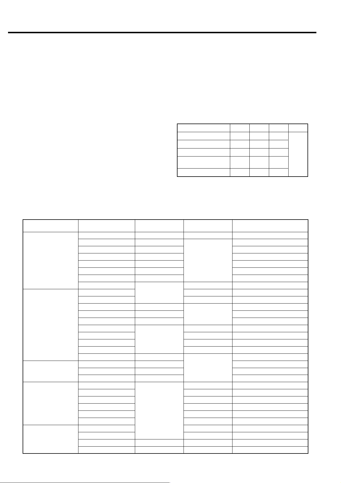
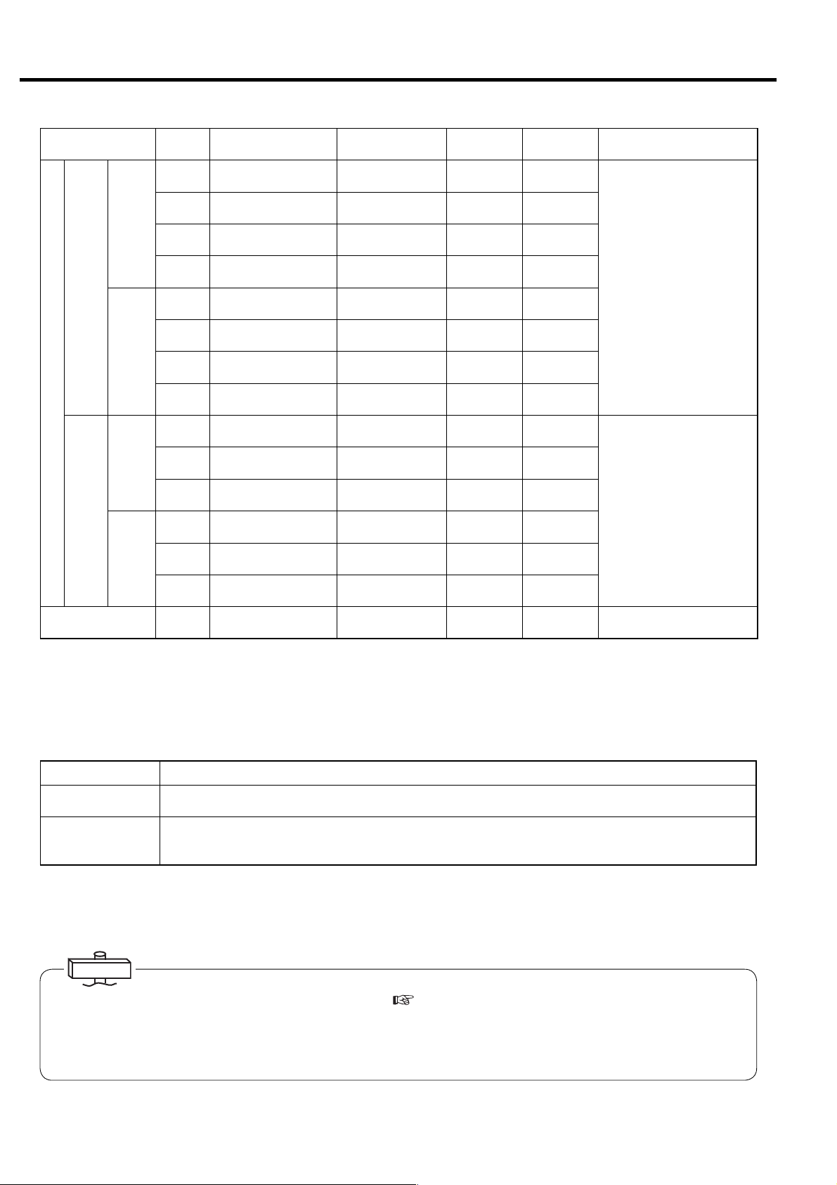
Digital Monitor Operation Classification
The following is a table of contents that can be set by
the LCD monitor and digital monitor (next section).
Function Item
MULTI-U SETTING
display
CONTROL SETTING
display
SCHEDULE SETTING
display
Other settings
Reset
MODE -
DUAL TIME
METHOD
SWITCHOVER
BACKUP
UNLOAD
ALT.TIME
CONTROL MODE
TYPE (left)
TYPE (center)
TYPE (right)
P-LOSS
PI-CA
P1
P2
TARGET - Prohibited to change
TIME LIMIT
TIME
MODE
START/STOP
RECORD 1, 2
Air compressor No.
IPI
Remote operation
Dryer operation
AUTO operation
ECOMODE
Shutdown/Alarm
Load count
Maintenance
Shutdwon/Alarm history
△
3-Language Display Switch
The language of the display can be switched to
Japanese, English or Chinese by the dip switch on
the back of the LCD monitor board. If the language
needs to be changed, consult with the local Hitachi
distributor.
Japanese OFF OFF OFF
English ON OFF OFF
Chinese OFF ON OFF
Setting for United
States
Test mode ON ON OFF
Power must be turned off before setting.
LCD monitor
operation
○
○
○
○
○
(automatic change)
-
○
○
○
-
○
○
○
○
-
○
-
Bit 1 2 3 4 - 8
ON OFF ON
Digital monitor
(F mode)
○ F000
-
○ (Factory set)
○ F019
○ F018
-
○ F022 -
○ F022 -
○ (Factory set)
-
○ F001
○ F002 -
○ F005 -
○ F008 -
○ F011 -
○
○
○
- Set button 7 sec. ON
○ F041
Dual, backup, etc
Differential pressure
Differential pressure
V type only
Example: I type (load/unload type)
Example: Setting 1
Option (not supported)
Option (not supported)
Option (not supported)
Setting 1, Setting 2
Setting 1, Setting 2
Energy saving mode decision time
Function switching
Operation data measurement
Display switch button operation
Reset button operation
Remote + display switch button
Remarks
Not
used
24
3. OPERATING PROCEDURE [How to Use the Digital Monitor]
3.4 How to Use the Digital Monitor
3.4.1 How to Display Operation Status, Shutdown History, and Status of Various Settings
All display contents of the digital monitor are linked with the LCD monitor. All of the following display contents can
be confirmed by the LCD monitor.
Use the following operations to display the contents of other operation/setting status on the LCD monitor and
readily confirm operation status and setting status by the digital monitor.
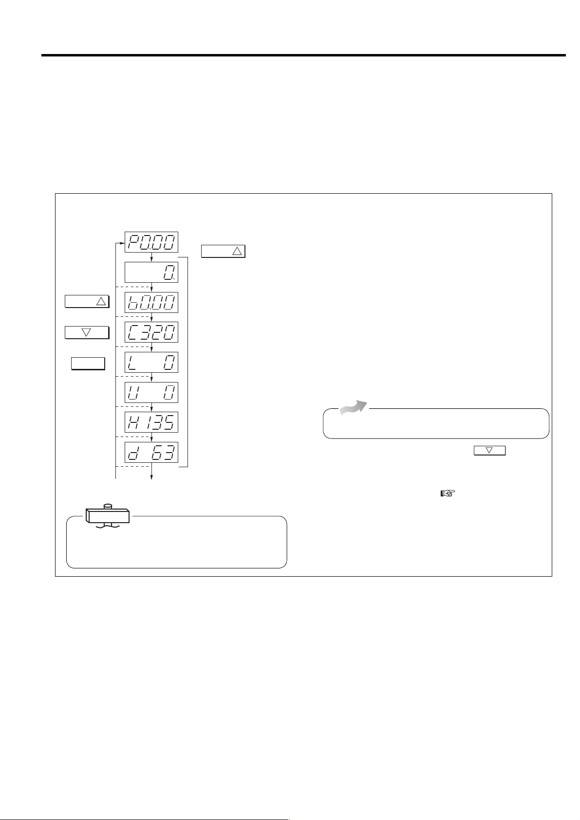
(1) How to Display the Operation Status
P: Discharge pressure (psi)
SELECT/WIDE
Blinks when operation time is added.
Total running hour (×10)
SEL ECT /WID E
Pres s once to go to
the next item.
Press once to go to
the previous item.
Return to discharge
pressure display
2
RESET
1
To shutdown history display
b: Interstage pressure (psi)
C: 1st-stage air end outlet temp (゜F)
(320゜F)
L: Vtype: Not in use
Fixed speed type: Load ratio (%)
U: Load count (×10,000 times)
H:
Vtype: Main motor operating frequency (Hz)
Fixed speed type: Not in use (display only)
d: Fan motor operating frequency (Hz)
Water-cooled type: Not in use (display only)
IMPORTANT
1. When other than P (Discharge pressure is
displayed), it automatically returns to P in 3 minutes.
2. Load ratio is a reference-calculated value.
1
Press
When the power is turned on, discharge pressure is displayed
on the screen of the digital monitor. Use the following
procedure to switch the digital monitor to other display.
① Press the SELECT/WIDE button. Operation time is
displayed on the screen.
② Press the SELECT/WIDE button. Interstage pressure is
displayed on the screen with “b.”
③ Press the SELECT/WIDE button. 1st-stage air end outlet
temperature is displayed on the screen with “C.”
④
Press the SELECT/WIDE button. Load rate is displayed
on
the screen with “L.”
⑤ Press the SELECT/WIDE button. Load count is displayed
on the screen in units of 10,000 times with “U.”
Air-Cooled
⑥ Press the SELECT/WIDE button. Operation frequency of
the fan motor is displayed on the screen with “d.”
To return to one item at a time, press the
2
button. To
return to discharge pressure, press the RESET button.
● If the alarm or shutdown light is blinking, the shutdown
code is displayed with “E0” (
page 36, 37).
“E0” indicates the contents of the latest shutdown.
● If the alarm or shutdown light is blinking, it indicates that
the alarm or shutdown has not been reset. Check E0.XX
and reset.
25
3. OPERATING PROCEDURE [How to Use the Digital Monitor]
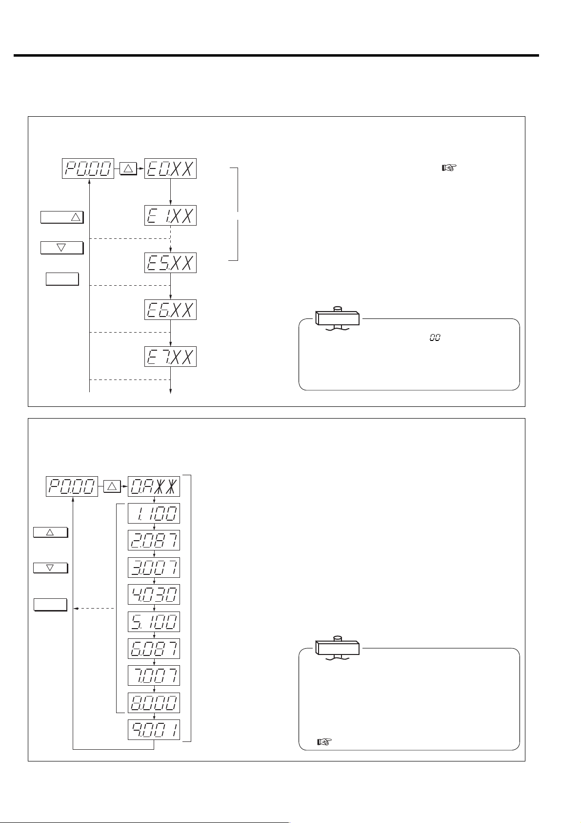
(2) How to Display Shutdown History
Discharge pressure display
SELECT/WIDE
Press once to go to
the next item.
Press once to go to
the previous item.
Return to discharge
pressure display.
1
2
RESET
SELECT/WIDE
1
Press 8 times.
[Latest shutdown]
[Previous shutdown]
XX : Shutdown code
[Oldest shutdown]
History consists of 6 date items.
Not used (display only)
Not used (display only)
To display of various settings
Use the following procedure to display shutdown history.
① Press the SELECT/WIDE button 8 times. “E0.” is the
displayed with the shutdown code (
Section 4). “0”
indicates the most recent shutdown. (The display
automatically changed to “E.0” when shutdown or alarm
occurs.)
② Press the SELECT/WIDE button. “E1.” is displayed along
with the shutdown code. “1” indicates shutdown that
occurred previously. Six items of data (0 to 5) are
recorded. “E5” indicates the oldest shutdown.
③ Press the RESET Button. The screen is returns to the
operation status.
IMPORTANT
If the shutdown code “XX ”is “ ”, it Indicates that
there is no shutdown history. Also, when anything
other than shutdown history is displayed without
shutdown resetting, the display is return to the latest
shutdown history in 3 minutes.
(3) How to Display Various Settings (Perform operation only when confirmation is
necessary.)
Dischargepressuredisplay
1
Proceeds by 1
each time pressed.
2
Returns by 1 each
time pressed.
RESET
Returns to
discharge pressure.
SWITCHDISPLAY
1
Press16times.
No.0 : Control status
A : Capacity control type
No.1 : Start pressure 1
100 : 100psi
No.2 : Recover pressure 1
087 : 87psi
No.3 : Pressure differential 1
007 : 7psi
No.4 : ECOMODE
Cycle time
30 second
No.5 : Start pressure 2
100 : 100psi
No.6 : Recover pressure 2
087 : 87psi
No.7 : Pressure differential 2
007 : 7psi
No.8 : Instantaneous power
interruption (IPI) setting
Invalid
:
000
No.9 : Compressor address
001 : No.1
Use the following procedure to display capacity control type
and pressure setting values for confirmation.
① Press the SELECT/WIDE button 16 times. “0.A**” is
then displayed on the screen. The content of “**” varies
depending on specifications. “A” may be “L” or “U”
depending on capacity control specifications.
② Consists of items 0 - 9. Pressure setting status and
optional pressure setting 2 can be confirmed each time
the SELECT/WIDE button is pressed.
③ Press the RESET Button. The screen is returns to the
usual discharge pressure display.
IMPORTANT
Symbol displayed at No. 0 and corresponding capacity
control type
A: AUTO function setting
L: Fixed speed type setting
(INTE …Load/unload operation)
U: Vtype setting (AUTO function canceled)
(
3.3.5 and 8.4)
26
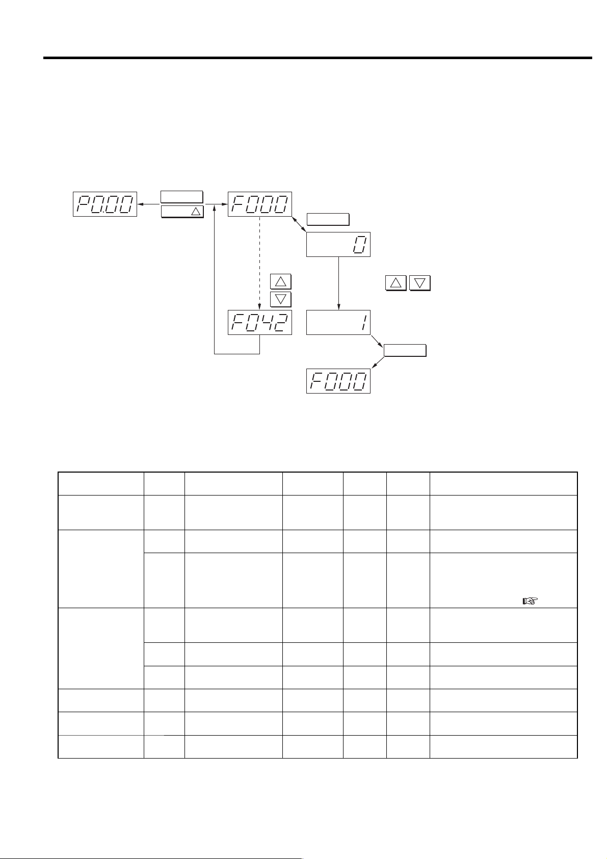
3. OPERATING PROCEDURE [How to Use the Digital Monitor]
3.4.2 How to Set Control Functions
■ Various settings (instantaneous power interruption (IPI), remote operation, capacity control
setting, pressure setting, etc.)
Switches the display from monitor mode to setting mode (F mode).
RESET
SELECT/WIDE
HolddowntheRESET
buttonandpressthe
SELECT/WIDEbutton
for3secondsor
moretochangeto
theFmode.Perform
sameoperationto
return.
1
Displays000thitemofFmode.
FUNC
SwitcheseachtimeFUNCispressed.
SeetheFmodetableformoredetail.
1
2
Forward
Back
Usebuttonstochangethevalue.
Displayssettingvalue.
F000:(0:SetsStandaloneoperation.)
2
1
F000:(1:Setsmultipleunitcontrol.)
STR
Back
PressSTRtostorethesetting.
Setting can be changed and memorized from the digital monitor without opening the control panel.
■ F Mode table
Function
Multiple unit control
setting
Instantaneous power
interruption (IPI)
restart setting
Remote operation
setting
7 segment
display
Item Range
F000 Control setting 0 - 1 1 0
F002
Instantaneous power
interruption (IPI) setting
0 - 1 1 0 0: Valid, 1: Invalid
Instantaneous power
F003
interruption (IPI)
1 - 5 1 sec 1
detection period setting
F005
F006
F007
Remote control switch
method
Remote operation
method
Remote shutdown
recovery
0 - 3 1 0
0 - 1 1 0 0: Pulse input, 1: Level input
0 - 1 1 0 0: Invalid, 1: Valid
Precision/
unit
Default Remarks
0: Stand alone operation,
1: Multiple unit control
(communication supported)
When the IPI function is available,
instantaneous power interruption is
detected between 20 ms and the
setting detection period set here, and
air compressor restarts. (
0: REMOTE button,
1: Local, 2: Remote,
3: Selectable by external contact
3.4.5).
AUTO setting F011 AUTO operation enabled 0 - 1 1 0 0: Valid, 1: Invalid
Capacity control F018
Function setting
(option)
F021 Pressure control system 0 - 2 1 0
Cut-in/Cut-out pressure
selection
0 - 2 1 0
0: Combination 1, 1: Combination 2,
2: Selectable by external contact
0: Built-in sensor, 1: External contact,
2: Selectable by external contact
27
3. OPERATING PROCEDURE [How to Use the Digital Monitor]
Function
Pressure
setting 1
※2
V type
Pressure
setting 2
※2
Pressure
setting 1
※2
100 / 125 psi (0.69 / 0.86 MPa) specifications
Fixed
speed
type
Pressure
setting 2
※2
7 segment
display
F022
F023
F024
F025
F031
F032
F033
F034
F023
F024
F025
F032
F033
F034
Item Range
Control pressure
setting 1 psi (MPa)
Cut-out pressure 1
psi (MPa)
Cut-in pressure 1
psi (MPa)
Restart pressure 1
psi (MPa)
Control pressure2
psi (MPa)
Cut-out pressure 2
psi (MPa)
Cut-in pressure 2
psi (MPa)
Restart
pressure 2
psi (MPa)
Cut-out pressure 1
psi (MPa)
Cut-in pressure 1
psi (MPa)
Restart pressure 1
psi (MPa)
Cut-out pressure 2
psi (MPa)
Cut-in pressure 2
psi (MPa)
Restart
pressure 2
psi (MPa)
71 〜 125
(0.5 〜 0.86)
71 〜 128
(0.5 〜 0.88)
71 〜 122
(0.5 〜 0.84)
71 〜 122
(0.5 〜 0.84)
71 〜 125
(0.5 〜 0.86)
71 〜 128
(0.5 〜 0.88)
71 〜 122
(0.5 〜 0.84)
71 〜 122
(0.5 〜 0.84)
71 〜 100 [125]
(0.5 〜 0.69 [0.86])
73 〜 86 [110]
(0.5 〜 0.59 [0.76])
73 〜 86 [110]
(0.5 〜 0.59 [0.76])
73 〜 100 [125]
(0.5 〜 0.69 [0.86])
73 〜 86 [110]
(0.5 〜 0.59 [0.76])
73 〜 86 [110]
(0.5 〜 0.59 [0.76])
Precision/
unit
1psi
(0.01MPa)
1psi
(0.01MPa)
1psi
(0.01MPa)
1psi
(0.01MPa)
1psi
(0.01MPa)
1psi
(0.01MPa)
1psi
(0.01MPa)
1psi
(0.01MPa)
1psi
(0.01MPa)
1psi
(0.01MPa)
1psi
(0.01MPa)
1psi
(0.01MPa)
1psi
(0.01MPa)
1psi
(0.01MPa)
Default Remarks
125
(0.86)
128
(0.88)
120
(0.83)
120
(0.83)
125
(0.86)
128
(0.88)
120
(0.83)
120
(0.83)
100 [125]
(0.69 [0.86])
85 [110]
(0.59 [0.76])
85 [110]
(0.59 [0.76])
100 [125]
(0.69 [0.86])
85 [110]
(0.59 [0.76])
85 [110]
(0.59 [0.76])
※Setting can be altered at
any time.
※Setting can be altered at
any time.
Shutdown history clear
F041 (*1)
History clear
0 〜 1
10
0:Enter, 1:History clear
Note:
※ Setting of the items without ※ in remarks can be memorized while the air compressor is stopped.
*1: When set to “1”, history is cleared. After clearing, the value is automatically reset to “0”.
*2: Refer to the below table about the Capacity control pressure setting conditions.
Do not change the setting of F items that are not specified in the table above.
● Capacity control pressure setting conditions
Type Setting conditions (Example of Pressure setting 1)
Fixed-speed
Variable-speed
Note 1: The same setting condition is applied for Pressure Setting 2 (F031 to F034).
IMPORTANT
1. Pressure setting when minimum air receiver tank is installed ( 5.4.4)
Vtype : Pressure differential between cut-out and cut-in shall be 7 psi (0.05 MPa) or more, and pressure differential between
cut-out and target shall be 3 psi (0.02 MPa) or more.
Fixed speed type : Pressure differential between cut-out and cut-in shall be 15 psi (0.1 MPa) or more.
2. External selection of Cut-in/Cut-out pressure combination 1 or 2 is an option. (F018-2)
① F023 shall be set F024 +3 psi (0.02 MPa) or higher, and F025+3 psi (0.02 MPa) or higher.
① F023 shall be set F022+3 psi (0.02 MPa) or higher.
② F024 and F025 shall be set F022 or lower.
28
 Loading...